US9878796B2 - Hybrid drive for gas turbine engine - Google Patents
Hybrid drive for gas turbine engineDownload PDFInfo
- Publication number
- US9878796B2 US9878796B2US14/620,259US201514620259AUS9878796B2US 9878796 B2US9878796 B2US 9878796B2US 201514620259 AUS201514620259 AUS 201514620259AUS 9878796 B2US9878796 B2US 9878796B2
- Authority
- US
- United States
- Prior art keywords
- fan
- rotor
- set forth
- drive
- gas turbine
- Prior art date
- Legal status (The legal status is an assumption and is not a legal conclusion. Google has not performed a legal analysis and makes no representation as to the accuracy of the status listed.)
- Active, expires
Links
Images


Classifications
- B—PERFORMING OPERATIONS; TRANSPORTING
- B64—AIRCRAFT; AVIATION; COSMONAUTICS
- B64D—EQUIPMENT FOR FITTING IN OR TO AIRCRAFT; FLIGHT SUITS; PARACHUTES; ARRANGEMENT OR MOUNTING OF POWER PLANTS OR PROPULSION TRANSMISSIONS IN AIRCRAFT
- B64D27/00—Arrangement or mounting of power plants in aircraft; Aircraft characterised by the type or position of power plants
- B64D27/02—Aircraft characterised by the type or position of power plants
- B64D27/24—Aircraft characterised by the type or position of power plants using steam or spring force
- F—MECHANICAL ENGINEERING; LIGHTING; HEATING; WEAPONS; BLASTING
- F02—COMBUSTION ENGINES; HOT-GAS OR COMBUSTION-PRODUCT ENGINE PLANTS
- F02C—GAS-TURBINE PLANTS; AIR INTAKES FOR JET-PROPULSION PLANTS; CONTROLLING FUEL SUPPLY IN AIR-BREATHING JET-PROPULSION PLANTS
- F02C7/00—Features, components parts, details or accessories, not provided for in, or of interest apart form groups F02C1/00 - F02C6/00; Air intakes for jet-propulsion plants
- F02C7/36—Power transmission arrangements between the different shafts of the gas turbine plant, or between the gas-turbine plant and the power user
- B—PERFORMING OPERATIONS; TRANSPORTING
- B64—AIRCRAFT; AVIATION; COSMONAUTICS
- B64D—EQUIPMENT FOR FITTING IN OR TO AIRCRAFT; FLIGHT SUITS; PARACHUTES; ARRANGEMENT OR MOUNTING OF POWER PLANTS OR PROPULSION TRANSMISSIONS IN AIRCRAFT
- B64D35/00—Transmitting power from power plants to propellers or rotors; Arrangements of transmissions
- B64D35/02—Transmitting power from power plants to propellers or rotors; Arrangements of transmissions specially adapted for specific power plants
- B64D35/021—Transmitting power from power plants to propellers or rotors; Arrangements of transmissions specially adapted for specific power plants for electric power plants
- B64D35/022—Transmitting power from power plants to propellers or rotors; Arrangements of transmissions specially adapted for specific power plants for electric power plants of hybrid-electric type
- B64D35/023—Transmitting power from power plants to propellers or rotors; Arrangements of transmissions specially adapted for specific power plants for electric power plants of hybrid-electric type of series-parallel type
- B—PERFORMING OPERATIONS; TRANSPORTING
- B64—AIRCRAFT; AVIATION; COSMONAUTICS
- B64D—EQUIPMENT FOR FITTING IN OR TO AIRCRAFT; FLIGHT SUITS; PARACHUTES; ARRANGEMENT OR MOUNTING OF POWER PLANTS OR PROPULSION TRANSMISSIONS IN AIRCRAFT
- B64D35/00—Transmitting power from power plants to propellers or rotors; Arrangements of transmissions
- B64D35/04—Transmitting power from power plants to propellers or rotors; Arrangements of transmissions characterised by the transmission driving a plurality of propellers or rotors
- F—MECHANICAL ENGINEERING; LIGHTING; HEATING; WEAPONS; BLASTING
- F01—MACHINES OR ENGINES IN GENERAL; ENGINE PLANTS IN GENERAL; STEAM ENGINES
- F01D—NON-POSITIVE DISPLACEMENT MACHINES OR ENGINES, e.g. STEAM TURBINES
- F01D15/00—Adaptations of machines or engines for special use; Combinations of engines with devices driven thereby
- F01D15/12—Combinations with mechanical gearing
- F—MECHANICAL ENGINEERING; LIGHTING; HEATING; WEAPONS; BLASTING
- F02—COMBUSTION ENGINES; HOT-GAS OR COMBUSTION-PRODUCT ENGINE PLANTS
- F02K—JET-PROPULSION PLANTS
- F02K3/00—Plants including a gas turbine driving a compressor or a ducted fan
- F02K3/02—Plants including a gas turbine driving a compressor or a ducted fan in which part of the working fluid by-passes the turbine and combustion chamber
- F02K3/04—Plants including a gas turbine driving a compressor or a ducted fan in which part of the working fluid by-passes the turbine and combustion chamber the plant including ducted fans, i.e. fans with high volume, low pressure outputs, for augmenting the jet thrust, e.g. of double-flow type
- F02K3/077—Plants including a gas turbine driving a compressor or a ducted fan in which part of the working fluid by-passes the turbine and combustion chamber the plant including ducted fans, i.e. fans with high volume, low pressure outputs, for augmenting the jet thrust, e.g. of double-flow type the plant being of the multiple flow type, i.e. having three or more flows
- B64D2027/026—
- B—PERFORMING OPERATIONS; TRANSPORTING
- B64—AIRCRAFT; AVIATION; COSMONAUTICS
- B64D—EQUIPMENT FOR FITTING IN OR TO AIRCRAFT; FLIGHT SUITS; PARACHUTES; ARRANGEMENT OR MOUNTING OF POWER PLANTS OR PROPULSION TRANSMISSIONS IN AIRCRAFT
- B64D27/00—Arrangement or mounting of power plants in aircraft; Aircraft characterised by the type or position of power plants
- B64D27/02—Aircraft characterised by the type or position of power plants
- B64D27/026—Aircraft characterised by the type or position of power plants comprising different types of power plants, e.g. combination of a piston engine and a gas-turbine
- F—MECHANICAL ENGINEERING; LIGHTING; HEATING; WEAPONS; BLASTING
- F05—INDEXING SCHEMES RELATING TO ENGINES OR PUMPS IN VARIOUS SUBCLASSES OF CLASSES F01-F04
- F05D—INDEXING SCHEME FOR ASPECTS RELATING TO NON-POSITIVE-DISPLACEMENT MACHINES OR ENGINES, GAS-TURBINES OR JET-PROPULSION PLANTS
- F05D2220/00—Application
- F05D2220/30—Application in turbines
- F05D2220/32—Application in turbines in gas turbines
- F05D2220/323—Application in turbines in gas turbines for aircraft propulsion, e.g. jet engines
- F—MECHANICAL ENGINEERING; LIGHTING; HEATING; WEAPONS; BLASTING
- F05—INDEXING SCHEMES RELATING TO ENGINES OR PUMPS IN VARIOUS SUBCLASSES OF CLASSES F01-F04
- F05D—INDEXING SCHEME FOR ASPECTS RELATING TO NON-POSITIVE-DISPLACEMENT MACHINES OR ENGINES, GAS-TURBINES OR JET-PROPULSION PLANTS
- F05D2220/00—Application
- F05D2220/30—Application in turbines
- F05D2220/36—Application in turbines specially adapted for the fan of turbofan engines
- F—MECHANICAL ENGINEERING; LIGHTING; HEATING; WEAPONS; BLASTING
- F05—INDEXING SCHEMES RELATING TO ENGINES OR PUMPS IN VARIOUS SUBCLASSES OF CLASSES F01-F04
- F05D—INDEXING SCHEME FOR ASPECTS RELATING TO NON-POSITIVE-DISPLACEMENT MACHINES OR ENGINES, GAS-TURBINES OR JET-PROPULSION PLANTS
- F05D2240/00—Components
- F05D2240/40—Use of a multiplicity of similar components
- F—MECHANICAL ENGINEERING; LIGHTING; HEATING; WEAPONS; BLASTING
- F05—INDEXING SCHEMES RELATING TO ENGINES OR PUMPS IN VARIOUS SUBCLASSES OF CLASSES F01-F04
- F05D—INDEXING SCHEME FOR ASPECTS RELATING TO NON-POSITIVE-DISPLACEMENT MACHINES OR ENGINES, GAS-TURBINES OR JET-PROPULSION PLANTS
- F05D2250/00—Geometry
- F05D2250/30—Arrangement of components
- F05D2250/31—Arrangement of components according to the direction of their main axis or their axis of rotation
- F05D2250/312—Arrangement of components according to the direction of their main axis or their axis of rotation the axes being parallel to each other
- F—MECHANICAL ENGINEERING; LIGHTING; HEATING; WEAPONS; BLASTING
- F05—INDEXING SCHEMES RELATING TO ENGINES OR PUMPS IN VARIOUS SUBCLASSES OF CLASSES F01-F04
- F05D—INDEXING SCHEME FOR ASPECTS RELATING TO NON-POSITIVE-DISPLACEMENT MACHINES OR ENGINES, GAS-TURBINES OR JET-PROPULSION PLANTS
- F05D2260/00—Function
- F05D2260/40—Transmission of power
- F05D2260/402—Transmission of power through friction drives
- F05D2260/4023—Transmission of power through friction drives through a friction clutch
- F—MECHANICAL ENGINEERING; LIGHTING; HEATING; WEAPONS; BLASTING
- F05—INDEXING SCHEMES RELATING TO ENGINES OR PUMPS IN VARIOUS SUBCLASSES OF CLASSES F01-F04
- F05D—INDEXING SCHEME FOR ASPECTS RELATING TO NON-POSITIVE-DISPLACEMENT MACHINES OR ENGINES, GAS-TURBINES OR JET-PROPULSION PLANTS
- F05D2260/00—Function
- F05D2260/40—Transmission of power
- F05D2260/403—Transmission of power through the shape of the drive components
- F05D2260/4031—Transmission of power through the shape of the drive components as in toothed gearing
- Y—GENERAL TAGGING OF NEW TECHNOLOGICAL DEVELOPMENTS; GENERAL TAGGING OF CROSS-SECTIONAL TECHNOLOGIES SPANNING OVER SEVERAL SECTIONS OF THE IPC; TECHNICAL SUBJECTS COVERED BY FORMER USPC CROSS-REFERENCE ART COLLECTIONS [XRACs] AND DIGESTS
- Y02—TECHNOLOGIES OR APPLICATIONS FOR MITIGATION OR ADAPTATION AGAINST CLIMATE CHANGE
- Y02T—CLIMATE CHANGE MITIGATION TECHNOLOGIES RELATED TO TRANSPORTATION
- Y02T50/00—Aeronautics or air transport
- Y02T50/60—Efficient propulsion technologies, e.g. for aircraft
- Y02T50/62—
- Y—GENERAL TAGGING OF NEW TECHNOLOGICAL DEVELOPMENTS; GENERAL TAGGING OF CROSS-SECTIONAL TECHNOLOGIES SPANNING OVER SEVERAL SECTIONS OF THE IPC; TECHNICAL SUBJECTS COVERED BY FORMER USPC CROSS-REFERENCE ART COLLECTIONS [XRACs] AND DIGESTS
- Y10—TECHNICAL SUBJECTS COVERED BY FORMER USPC
- Y10S—TECHNICAL SUBJECTS COVERED BY FORMER USPC CROSS-REFERENCE ART COLLECTIONS [XRACs] AND DIGESTS
- Y10S903/00—Hybrid electric vehicles, HEVS
- Y10S903/902—Prime movers comprising electrical and internal combustion motors
- Y10S903/903—Prime movers comprising electrical and internal combustion motors having energy storing means, e.g. battery, capacitor
Definitions
- Gas turbine enginesare known and are often mounted on aircraft.
- a fandelivers air into a core engine, and into a bypass housing as propulsion air.
- the air in the core housingpasses to a compressor where it is compressed, and then delivered into a combustion section.
- the airis mixed with fuel in the combustion section and ignited. Products of this combustion pass downstream over a turbine rotor, driving the turbine rotor to rotate, and in turn drive the compressor and fan rotors.
- the engineIn standard gas turbine engines, the engine is maintained operating throughout the entire flight of the associated aircraft. As known, the engine has high power conditions at take-off, and landing. the gas turbine engine would otherwise be shut down, saving fuel.
- the proposed systemhas positioned the electric motor in the path of exhaust gas, and downstream of the turbine rotor. This is a very high temperature location, and results in challenges to maintaining the electric motor, and associated wires, etc., operational.
- a gas turbine enginehas a fan drive turbine for selectively driving a fan rotor.
- a drive shaft between the fan drive turbine and the fan rotorincludes a clutch, and an electric motor.
- the electric motoris positioned such that it is not downstream of a flow path relative to the fan drive turbine.
- the fan drive turbinedrives a shaft extending through a core engine duct delivering air into a compressor rotor.
- the shaftdrives a bevel gear to in turn drive the fan rotor.
- the clutchis also positioned radially outwardly of the core engine duct.
- the fan drive turbine rotoralso drives a compressor rotor.
- An upstream and intermediate turbine rotoreach drive a compressor rotor.
- a downstream of the three turbine rotorsis the fan drive turbine.
- a controlmay open the clutch when an associated aircraft is at cruise altitude.
- the motoris operated when the associated aircraft is at cruise altitude.
- an axially outer location of the gas turbine engineis defined as the location of the fan rotor.
- the electric motoris positioned axially intermediate the fan rotor and the combustor.
- the clutchis closed at least when the associated aircraft is at take-off conditions.
- a method of operating a gas turbine enginecomprises ng the steps of driving a turbine rotor through a clutch to drive an associated fan rotor, and providing an electric motor for selectively driving the fan motor, driving the fan rotor with the clutch closed by the gas turbine engine when an associated aircraft is at a relatively high power condition, and opening the clutch, stopping operation of the gas turbine engine, and driving the fan rotor through the electric motor when the associated aircraft is at a low power condition.
- the electric motoris positioned such that it is not downstream of a flow path for products of combustion having passed downstream of a fan drive turbine rotor, that is driving the fan rotor.
- the fan drive turbinedrives a shaft extending through a core engine duct delivering air into a compressor rotor.
- the shaftdrives a bevel gear to in turn drive the fan rotor.
- the electric motoris positioned radially outwardly of the core engine duct.
- the clutchis also positioned radially outwardly of the core engine duct.
- the fan drive turbine rotoralso drives a compressor rotor.
- An upstream and intermediate turbine rotoreach drive the compressor rotor, and a downstream of the three turbine rotors is the fan drive turbine rotor
- the clutchis opened when an associated aircraft is at cruise altitude.
- the motoris operated when the associated aircraft is at cruise altitude.
- an axially outer location of the gas turbine engineis defined as the location of the fan rotor.
- the electric motoris positioned axially intermediate the fan rotor and the combustor.
- the clutchis closed at least when the associated aircraft is at take-off conditions.
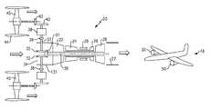
- FIG. 1Aschematically shows a gas turbine engine.
- FIG. 1Bshows an aircraft
- FIG. 2shows a second embodiment
- FIG. 3shows the FIG. 1A engine in a low power operational mode.
- FIG. 1AAn engine 20 is illustrated in FIG. 1A having an upstream or low pressure compressor rotor 22 , and a downstream or high pressure compressor rotor 24 .
- a high pressure or upstream turbine rotor 26drives compressor rotor 24 .
- a downstream or low pressure turbine rotor 28drives the compressor rotor 22 .
- a combustion section 29is positioned intermediate compressor rotor 24 and turbine rotor 26 . As known, air is received from a core inlet 34 , compressed across compressor rotors 22 and 24 . That air is delivered into the combustion section 29 where it is mixed with fuel and ignited.
- Products of this combustionpass downstream over turbine rotors 26 and 28 , driving them to rotate.
- the product of this combustionthen passes through an exhaust duct 27 .
- products of the combustion in the exhaust duct 27are very hot.
- a shaft 30is also driven by the downstream turbine rotor 28 , and includes a gear 31 that drives bevel gears 32 to in turn drive a shaft 33 through a clutch 36 .
- An electric motor 38is positioned between the clutch 36 and a gear 40 .
- Gear 40engages a gear 42 to drive the fan rotor 45 .
- Fan rotor 45is driven within a bypass duct 44 .
- engine 50there may be a compressor rotors 58 and 60 driven by turbine rotors 62 and 56 , similar to the FIG. 1 embodiment.
- a combustion section 64provides products of combustion to drive the turbine rotors 62 and 56 .
- a third turbine rotor 52drives a shaft 54 to in turn drive the fan rotors, such as fan rotor 45 as shown in FIG. 1A . That is, shaft 54 drives a gear arrangement as shown in FIG. 1A .
- an associated aircraft 16may mount two engines, that may be either like engine 20 or 50 . Of course, other numbers of engines may be used. While the engine inlet and exhaust are not illustrated in FIG. 1B , such would be along the airframe fuselage.
- FIG. 3shows a low pressure condition for the FIG. 1A engine. It should be understood that a similar operational strategy can be utilized with a FIG. 2 type engine.
- gears 31 and 32may provide a gear reduction, such that the fan rotor 45 rotates at a slower speed than the compressor rotor 22 , or the turbine rotor 28 .
- the engine 20(or 50 ) is operated, such that combustion occurs in the combustion section, and the turbine rotors 26 and 28 (or 62 / 56 / 52 ) are driven.
- the clutch 36may be opened as shown at 136 in FIG. 3 .
- the electric motor 38is operated to drive the fan rotors 45 . Under such conditions, only the bypass propulsion air provided by the fan rotors 45 will be driving the aircraft 16 .
- the engine 20(or 50 ) may be restarted, the clutch 36 closed, and the motor 38 stopped.
- the motor 38could also supplement power to the fan while the engine is running. It should be understood that the motor is constructed such that it passes rotation to gear 40 from shaft 30 even when motor 38 is shut down. However, by positioning the motor 38 , and clutch 36 , in a relatively low temperature location, the conditions that must be survived by these components are simplified compared to the proposed electric motor positioned in the path of hot products of combustion as in the prior art.
- one way of defining the location for motor 38would be to say it is upstream of combustor 29 , or axially outward of the combustor 29 , with an axially forward position being defined by the location of the fan rotors 45 .
- Another way of defining the location of the motors 38is to say that they are positioned radially outward, defined by an axis of rotation of shaft 30 , relative to a core engine housing 131 .
- Another way of defining the locationwould be to say that the motor is not located in the path of the products of combustion. Stated another way, the electric motor 38 is positioned such that it is not downstream of a flow path relative to the fan driving turbine rotors 28 or 52 .
- An axially outer location of the gas turbine engineis defined as the location of the fan rotor.
- the electric motoris positioned axially intermediate the fan rotor and the combustor.
- an appropriate motor controllerwhich may otherwise function as a full authority digital electronic controller (FADEC) may control the operation of the core engine and the fan.
- FADECfull authority digital electronic controller
Landscapes
- Engineering & Computer Science (AREA)
- Mechanical Engineering (AREA)
- Chemical & Material Sciences (AREA)
- Combustion & Propulsion (AREA)
- General Engineering & Computer Science (AREA)
- Aviation & Aerospace Engineering (AREA)
- Structures Of Non-Positive Displacement Pumps (AREA)
Abstract
Description
Claims (22)
Priority Applications (1)
| Application Number | Priority Date | Filing Date | Title |
|---|---|---|---|
| US14/620,259US9878796B2 (en) | 2014-03-27 | 2015-02-12 | Hybrid drive for gas turbine engine |
Applications Claiming Priority (3)
| Application Number | Priority Date | Filing Date | Title |
|---|---|---|---|
| US201461971086P | 2014-03-27 | 2014-03-27 | |
| US201461971085P | 2014-03-27 | 2014-03-27 | |
| US14/620,259US9878796B2 (en) | 2014-03-27 | 2015-02-12 | Hybrid drive for gas turbine engine |
Publications (2)
| Publication Number | Publication Date |
|---|---|
| US20150274306A1 US20150274306A1 (en) | 2015-10-01 |
| US9878796B2true US9878796B2 (en) | 2018-01-30 |
Family
ID=54189277
Family Applications (1)
| Application Number | Title | Priority Date | Filing Date |
|---|---|---|---|
| US14/620,259Active2036-04-03US9878796B2 (en) | 2014-03-27 | 2015-02-12 | Hybrid drive for gas turbine engine |
Country Status (1)
| Country | Link |
|---|---|
| US (1) | US9878796B2 (en) |
Cited By (7)
| Publication number | Priority date | Publication date | Assignee | Title |
|---|---|---|---|---|
| US20170240286A1 (en)* | 2015-10-05 | 2017-08-24 | Safran Aircraft Engines | Aircraft with a propulsion unit with offset fan |
| US20190322382A1 (en)* | 2018-04-19 | 2019-10-24 | The Boeing Company | Hybrid propulsion engines for aircraft |
| US20190368370A1 (en)* | 2018-06-05 | 2019-12-05 | United Technologies Corporation | Hybrid electric turbine engine |
| US10968825B2 (en) | 2018-04-19 | 2021-04-06 | The Boeing Company | Flow multiplier systems for aircraft |
| US10981660B2 (en) | 2018-04-19 | 2021-04-20 | The Boeing Company | Hybrid propulsion engines for aircraft |
| US20210284352A1 (en)* | 2018-08-30 | 2021-09-16 | Aurora Flight Sciences Corporation, a subsidiary of The Boeing Company | Mechanically-Distributed Propulsion Drivetrain and Architecture |
| US11572190B2 (en)* | 2017-09-29 | 2023-02-07 | Rolls-Royce Deutschland Ltd & Co Kg | Method for propelling an aircraft, propulsion system, and aircraft |
Families Citing this family (32)
| Publication number | Priority date | Publication date | Assignee | Title |
|---|---|---|---|---|
| US9540113B2 (en)* | 2013-03-11 | 2017-01-10 | United Technologies Corporation | De-couple geared turbo-fan engine and aircraft |
| FR3029172B1 (en)* | 2014-11-27 | 2018-05-25 | Safran Helicopter Engines | PROPULSE GROUP WITH SELECTIVE COUPLING MEANS |
| FR3041934B1 (en)* | 2015-10-05 | 2018-07-13 | Safran Aircraft Engines | PROPELLER ASSEMBLY OF AN AIRCRAFT |
| US10421554B2 (en)* | 2015-10-05 | 2019-09-24 | United Technologies Corporation | Double propulsor imbedded in aircraft tail with single core engine |
| FR3041996B1 (en)* | 2015-10-05 | 2017-10-27 | Snecma | SYSTEM FOR SUSPENSION OF TWO MODULES OF A PROPULSIVE ASSEMBLY |
| US10227137B2 (en)* | 2016-03-22 | 2019-03-12 | Ge Aviation Systems Llc | Hybrid power system for an aircraft |
| GB201615900D0 (en) | 2016-09-19 | 2016-11-02 | Rolls Royce Plc | Aircraft propulsion system |
| US10618667B2 (en)* | 2016-10-31 | 2020-04-14 | Rolls-Royce Corporation | Fan module with adjustable pitch blades and power system |
| US20180163664A1 (en)* | 2016-12-08 | 2018-06-14 | United Technologies Corporation | Concentric shafts driving adjacent fans for aircraft propulsion |
| US10428740B2 (en)* | 2016-12-08 | 2019-10-01 | United Technologies Corporation | Twin shafts driving adjacent fans for aircraft propulsion |
| US10837304B2 (en)* | 2016-12-13 | 2020-11-17 | General Electric Company | Hybrid-electric drive system |
| US20200003115A1 (en)* | 2017-02-08 | 2020-01-02 | Florida Turbine Technologies, Inc. | Turbocharged gas turbine engine with electric power generation for small aircraft electric propulsion |
| US10689082B2 (en)* | 2017-04-12 | 2020-06-23 | Rolls-Royce North American Technologies, Inc. | Mechanically and electrically distributed propulsion |
| FR3066444B1 (en)* | 2017-05-19 | 2021-04-16 | Safran | HYBRID PROPULSIVE AIRCRAFT ARCHITECTURE INCLUDING AN ENGINE WITH A REVERSIBLE ELECTRIC MACHINE MOUNTED ON TWO SHAFTS |
| US20190002117A1 (en) | 2017-06-30 | 2019-01-03 | General Electric Company | Propulsion system for an aircraft |
| US20200277078A1 (en)* | 2019-03-01 | 2020-09-03 | Pratt & Whitney Canada Corp. | Electrical power system for aircraft having hybrid-electric propulsion system |
| US11628942B2 (en) | 2019-03-01 | 2023-04-18 | Pratt & Whitney Canada Corp. | Torque ripple control for an aircraft power train |
| EP3931091A4 (en) | 2019-03-01 | 2023-01-11 | Pratt & Whitney Canada Corp. | DISTRIBUTED PROPULSION CONFIGURATIONS FOR AIRCRAFT WITH MIXED PROPULSION SYSTEMS |
| US12240619B2 (en) | 2019-03-01 | 2025-03-04 | Pratt & Whitney Canada Corp. | Torque balancing for hybrid electric propulsion systems and aircraft utilizing hybrid electric propulsion systems |
| US11732639B2 (en) | 2019-03-01 | 2023-08-22 | Pratt & Whitney Canada Corp. | Mechanical disconnects for parallel power lanes in hybrid electric propulsion systems |
| US11535392B2 (en) | 2019-03-18 | 2022-12-27 | Pratt & Whitney Canada Corp. | Architectures for hybrid-electric propulsion |
| US11326467B2 (en) | 2019-06-14 | 2022-05-10 | Raytheon Technologies Corporation | Dual drive electro-aero-thermal turbine engine |
| US11286054B2 (en)* | 2019-10-02 | 2022-03-29 | The Boeing Company | Dual hybrid propulsion system for an aircraft having a cross-connecting clutch |
| US11486472B2 (en) | 2020-04-16 | 2022-11-01 | United Technologies Advanced Projects Inc. | Gear sytems with variable speed drive |
| US12031479B2 (en)* | 2020-08-31 | 2024-07-09 | General Electric Company | Hybrid electric propulsion system load share |
| DE102021202487A1 (en)* | 2021-03-15 | 2022-09-15 | Zf Friedrichshafen Ag | Aviation propulsion system of an aircraft |
| US11873081B2 (en) | 2021-06-09 | 2024-01-16 | Textron Innovations Inc. | Supplemental engine power control |
| US12054268B2 (en)* | 2021-10-19 | 2024-08-06 | Duxion Motors, Inc. | Hybrid propulsion system including electric motor with fan shroud encircling integrated fan blades |
| US20230138476A1 (en)* | 2021-10-29 | 2023-05-04 | Raytheon Technologies Corporation | Hybrid electric single engine descent restart |
| US20230138513A1 (en)* | 2021-10-29 | 2023-05-04 | Embraer S.A. | Twin propulsor, parallel hybrid, streamlined nacelle propulsion system |
| US12077308B2 (en) | 2022-04-14 | 2024-09-03 | Textron Innovations Inc. | Supplemental engine transition control |
| US12054245B2 (en)* | 2022-07-18 | 2024-08-06 | Textron Innovations Inc. | Optimizing usage of supplemental engine power |
Citations (9)
| Publication number | Priority date | Publication date | Assignee | Title |
|---|---|---|---|---|
| US5114103A (en)* | 1990-08-27 | 1992-05-19 | General Electric Company | Aircraft engine electrically powered boundary layer bleed system |
| US20060011780A1 (en) | 2004-07-16 | 2006-01-19 | Brand Joseph H | Aircraft propulsion system |
| US20090056309A1 (en)* | 2007-08-30 | 2009-03-05 | United Technologies Corp. | Gas Turbine Engine Systems and Related Methods Involving Multiple Gas Turbine Cores |
| US20090289456A1 (en)* | 2008-05-23 | 2009-11-26 | Rolls-Royce Plc | Gas turbine engine apparatus |
| US20090293494A1 (en) | 2006-11-29 | 2009-12-03 | Airbus Deutschland Gmbh | Hybrid drive for an aircraft |
| US20100000226A1 (en)* | 2008-07-03 | 2010-01-07 | Rolls-Royce Deutschland Ltd & Co Kg | Turbofan engine with at least one apparatus for driving at least one generator |
| US20100219779A1 (en)* | 2009-03-02 | 2010-09-02 | Rolls-Royce Plc | Variable drive gas turbine engine |
| US20130134264A1 (en) | 2011-11-28 | 2013-05-30 | Carter Aviation Technologies, Llc | Electric Motor Powered Rotor Drive for Slowed Rotor Winged Aircraft |
| US20160097328A1 (en)* | 2014-10-03 | 2016-04-07 | Pratt & Whitney Canada Corp. | Accessory drive system for a gas turbine engine |
- 2015
- 2015-02-12USUS14/620,259patent/US9878796B2/enactiveActive
Patent Citations (11)
| Publication number | Priority date | Publication date | Assignee | Title |
|---|---|---|---|---|
| US5114103A (en)* | 1990-08-27 | 1992-05-19 | General Electric Company | Aircraft engine electrically powered boundary layer bleed system |
| US20060011780A1 (en) | 2004-07-16 | 2006-01-19 | Brand Joseph H | Aircraft propulsion system |
| US7540450B2 (en)* | 2004-07-16 | 2009-06-02 | Pratt & Whitney Canada Corp. | Aircraft propulsion system |
| US20090293494A1 (en) | 2006-11-29 | 2009-12-03 | Airbus Deutschland Gmbh | Hybrid drive for an aircraft |
| US20090056309A1 (en)* | 2007-08-30 | 2009-03-05 | United Technologies Corp. | Gas Turbine Engine Systems and Related Methods Involving Multiple Gas Turbine Cores |
| US20090289456A1 (en)* | 2008-05-23 | 2009-11-26 | Rolls-Royce Plc | Gas turbine engine apparatus |
| US20100000226A1 (en)* | 2008-07-03 | 2010-01-07 | Rolls-Royce Deutschland Ltd & Co Kg | Turbofan engine with at least one apparatus for driving at least one generator |
| US20100219779A1 (en)* | 2009-03-02 | 2010-09-02 | Rolls-Royce Plc | Variable drive gas turbine engine |
| EP2226487A2 (en) | 2009-03-02 | 2010-09-08 | Rolls-Royce plc | Variable drive gas turbine engine |
| US20130134264A1 (en) | 2011-11-28 | 2013-05-30 | Carter Aviation Technologies, Llc | Electric Motor Powered Rotor Drive for Slowed Rotor Winged Aircraft |
| US20160097328A1 (en)* | 2014-10-03 | 2016-04-07 | Pratt & Whitney Canada Corp. | Accessory drive system for a gas turbine engine |
Non-Patent Citations (2)
| Title |
|---|
| European Search Report for European Application No. 15160776.9 dated Sep. 5, 2015. |
| Hybrid Help, article, Aviation Week & Space Technology, Jan. 27, 2014. |
Cited By (11)
| Publication number | Priority date | Publication date | Assignee | Title |
|---|---|---|---|---|
| US20170240286A1 (en)* | 2015-10-05 | 2017-08-24 | Safran Aircraft Engines | Aircraft with a propulsion unit with offset fan |
| US10850859B2 (en)* | 2015-10-05 | 2020-12-01 | Safran Aircraft Engines | Aircraft with a propulsion unit with offset fan |
| US11572190B2 (en)* | 2017-09-29 | 2023-02-07 | Rolls-Royce Deutschland Ltd & Co Kg | Method for propelling an aircraft, propulsion system, and aircraft |
| US20190322382A1 (en)* | 2018-04-19 | 2019-10-24 | The Boeing Company | Hybrid propulsion engines for aircraft |
| US10968825B2 (en) | 2018-04-19 | 2021-04-06 | The Boeing Company | Flow multiplier systems for aircraft |
| US10981660B2 (en) | 2018-04-19 | 2021-04-20 | The Boeing Company | Hybrid propulsion engines for aircraft |
| US11053019B2 (en)* | 2018-04-19 | 2021-07-06 | The Boeing Company | Hybrid propulsion engines for aircraft |
| US20190368370A1 (en)* | 2018-06-05 | 2019-12-05 | United Technologies Corporation | Hybrid electric turbine engine |
| US10641124B2 (en)* | 2018-06-05 | 2020-05-05 | United Technologies Corporation | Hybrid electric turbine engine |
| US20210284352A1 (en)* | 2018-08-30 | 2021-09-16 | Aurora Flight Sciences Corporation, a subsidiary of The Boeing Company | Mechanically-Distributed Propulsion Drivetrain and Architecture |
| US12110846B2 (en)* | 2018-08-30 | 2024-10-08 | Aurora Flight Sciences Corporation, a subsidiary of The Boeing Company | Mechanically-distributed propulsion drivetrain and architecture |
Also Published As
| Publication number | Publication date |
|---|---|
| US20150274306A1 (en) | 2015-10-01 |
Similar Documents
| Publication | Publication Date | Title |
|---|---|---|
| US9878796B2 (en) | Hybrid drive for gas turbine engine | |
| US8887485B2 (en) | Three spool gas turbine engine having a clutch and compressor bypass | |
| US12065973B2 (en) | Electric enhanced transmission for multi-spool load-sharing turbofan engine | |
| EP3139021B1 (en) | Reverse core gear turbofan | |
| EP2929162B1 (en) | Gas turbine engine with dual filtration particle separator | |
| EP3406519B1 (en) | Dedicated fans for boundary layer ingestion | |
| CA2762849C (en) | Variable cycle gas turbine engine | |
| EP2924247B1 (en) | Hybrid drive for gas turbine engine | |
| GB2536847A (en) | Supply of air to an air-conditioning circuit of an aircraft cabin from its turboprop engine | |
| RU2659133C2 (en) | Turbofan reducer engine, which is equipped with the low pressure system for controlling the aircraft environment | |
| US9989011B2 (en) | Reverse flow single spool core gas turbine engine | |
| WO2014092750A1 (en) | Gas turbine engine with cooling scheme for drive gear system and pitch control | |
| US10526915B2 (en) | Firewall mount hub | |
| EP3486455A1 (en) | Hybrid compressor bleed air for aircraft use | |
| EP3392150B1 (en) | Variable-geometry boundary layer diverter | |
| EP2902608B1 (en) | Aft shrouded geared turbofan | |
| EP3273030B1 (en) | Embedded engine using boundary layer cooling air | |
| US9771863B2 (en) | Gas turbine engine with embedded distributed fans | |
| US9909495B2 (en) | Gas turbine engine with distributed fans with drive control | |
| US10174680B2 (en) | Gas turbine engine with distributed fans and bypass air mixer |
Legal Events
| Date | Code | Title | Description |
|---|---|---|---|
| STCF | Information on status: patent grant | Free format text:PATENTED CASE | |
| AS | Assignment | Owner name:RAYTHEON TECHNOLOGIES CORPORATION, MASSACHUSETTS Free format text:CHANGE OF NAME;ASSIGNOR:UNITED TECHNOLOGIES CORPORATION;REEL/FRAME:054062/0001 Effective date:20200403 | |
| AS | Assignment | Owner name:RAYTHEON TECHNOLOGIES CORPORATION, CONNECTICUT Free format text:CORRECTIVE ASSIGNMENT TO CORRECT THE AND REMOVE PATENT APPLICATION NUMBER 11886281 AND ADD PATENT APPLICATION NUMBER 14846874. TO CORRECT THE RECEIVING PARTY ADDRESS PREVIOUSLY RECORDED AT REEL: 054062 FRAME: 0001. ASSIGNOR(S) HEREBY CONFIRMS THE CHANGE OF ADDRESS;ASSIGNOR:UNITED TECHNOLOGIES CORPORATION;REEL/FRAME:055659/0001 Effective date:20200403 | |
| MAFP | Maintenance fee payment | Free format text:PAYMENT OF MAINTENANCE FEE, 4TH YEAR, LARGE ENTITY (ORIGINAL EVENT CODE: M1551); ENTITY STATUS OF PATENT OWNER: LARGE ENTITY Year of fee payment:4 | |
| AS | Assignment | Owner name:RTX CORPORATION, CONNECTICUT Free format text:CHANGE OF NAME;ASSIGNOR:RAYTHEON TECHNOLOGIES CORPORATION;REEL/FRAME:064714/0001 Effective date:20230714 | |
| MAFP | Maintenance fee payment | Free format text:PAYMENT OF MAINTENANCE FEE, 8TH YEAR, LARGE ENTITY (ORIGINAL EVENT CODE: M1552); ENTITY STATUS OF PATENT OWNER: LARGE ENTITY Year of fee payment:8 |