US9877717B2 - Connector for mesh support insertion - Google Patents
Connector for mesh support insertionDownload PDFInfo
- Publication number
- US9877717B2 US9877717B2US13/034,842US201113034842AUS9877717B2US 9877717 B2US9877717 B2US 9877717B2US 201113034842 AUS201113034842 AUS 201113034842AUS 9877717 B2US9877717 B2US 9877717B2
- Authority
- US
- United States
- Prior art keywords
- connector
- insertion needle
- surgical system
- sling
- extending
- Prior art date
- Legal status (The legal status is an assumption and is not a legal conclusion. Google has not performed a legal analysis and makes no representation as to the accuracy of the status listed.)
- Expired - Fee Related, expires
Links
- 238000003780insertionMethods0.000titleclaimsabstractdescription124
- 230000037431insertionEffects0.000titleclaimsabstractdescription124
- 239000007943implantSubstances0.000claimsabstractdescription18
- 239000000463materialSubstances0.000claimsdescription3
- 206010021639IncontinenceDiseases0.000claimsdescription2
- 230000007246mechanismEffects0.000description20
- 238000000034methodMethods0.000description12
- 238000001356surgical procedureMethods0.000description4
- 238000000465mouldingMethods0.000description3
- 230000008569processEffects0.000description2
- 238000011282treatmentMethods0.000description2
- 208000012287ProlapseDiseases0.000description1
- 206010066218Stress Urinary IncontinenceDiseases0.000description1
- 230000009471actionEffects0.000description1
- 230000008901benefitEffects0.000description1
- 238000011109contaminationMethods0.000description1
- 238000007796conventional methodMethods0.000description1
- 238000012986modificationMethods0.000description1
- 230000004048modificationEffects0.000description1
- 210000004197pelvisAnatomy0.000description1
- 230000003014reinforcing effectEffects0.000description1
- 230000004044responseEffects0.000description1
- 230000007704transitionEffects0.000description1
- 210000004291uterusAnatomy0.000description1
- 238000003466weldingMethods0.000description1
Images


Classifications
- A—HUMAN NECESSITIES
- A61—MEDICAL OR VETERINARY SCIENCE; HYGIENE
- A61B—DIAGNOSIS; SURGERY; IDENTIFICATION
- A61B17/00—Surgical instruments, devices or methods
- A61B17/04—Surgical instruments, devices or methods for suturing wounds; Holders or packages for needles or suture materials
- A61B17/06—Needles ; Sutures; Needle-suture combinations; Holders or packages for needles or suture materials
- A61B17/06066—Needles, e.g. needle tip configurations
- A61B17/06109—Big needles, either gripped by hand or connectable to a handle
- A—HUMAN NECESSITIES
- A61—MEDICAL OR VETERINARY SCIENCE; HYGIENE
- A61B—DIAGNOSIS; SURGERY; IDENTIFICATION
- A61B17/00—Surgical instruments, devices or methods
- A61B2017/00743—Type of operation; Specification of treatment sites
- A61B2017/00805—Treatment of female stress urinary incontinence
- A—HUMAN NECESSITIES
- A61—MEDICAL OR VETERINARY SCIENCE; HYGIENE
- A61B—DIAGNOSIS; SURGERY; IDENTIFICATION
- A61B17/00—Surgical instruments, devices or methods
- A61B17/04—Surgical instruments, devices or methods for suturing wounds; Holders or packages for needles or suture materials
- A61B17/06—Needles ; Sutures; Needle-suture combinations; Holders or packages for needles or suture materials
- A61B17/06004—Means for attaching suture to needle
- A61B2017/06009—Means for attaching suture to needle having additional means for releasably clamping the suture to the needle, e.g. actuating rod slideable within the needle
- A—HUMAN NECESSITIES
- A61—MEDICAL OR VETERINARY SCIENCE; HYGIENE
- A61B—DIAGNOSIS; SURGERY; IDENTIFICATION
- A61B17/00—Surgical instruments, devices or methods
- A61B17/04—Surgical instruments, devices or methods for suturing wounds; Holders or packages for needles or suture materials
- A61B17/06—Needles ; Sutures; Needle-suture combinations; Holders or packages for needles or suture materials
- A61B17/06004—Means for attaching suture to needle
- A61B2017/06042—Means for attaching suture to needle located close to needle tip
- A—HUMAN NECESSITIES
- A61—MEDICAL OR VETERINARY SCIENCE; HYGIENE
- A61F—FILTERS IMPLANTABLE INTO BLOOD VESSELS; PROSTHESES; DEVICES PROVIDING PATENCY TO, OR PREVENTING COLLAPSING OF, TUBULAR STRUCTURES OF THE BODY, e.g. STENTS; ORTHOPAEDIC, NURSING OR CONTRACEPTIVE DEVICES; FOMENTATION; TREATMENT OR PROTECTION OF EYES OR EARS; BANDAGES, DRESSINGS OR ABSORBENT PADS; FIRST-AID KITS
- A61F2/00—Filters implantable into blood vessels; Prostheses, i.e. artificial substitutes or replacements for parts of the body; Appliances for connecting them with the body; Devices providing patency to, or preventing collapsing of, tubular structures of the body, e.g. stents
- A61F2/0004—Closure means for urethra or rectum, i.e. anti-incontinence devices or support slings against pelvic prolapse
- A61F2/0031—Closure means for urethra or rectum, i.e. anti-incontinence devices or support slings against pelvic prolapse for constricting the lumen; Support slings for the urethra
- A61F2/0036—Closure means for urethra or rectum, i.e. anti-incontinence devices or support slings against pelvic prolapse for constricting the lumen; Support slings for the urethra implantable
- A61F2/0045—Support slings
Definitions
- the inventionrelates generally to treatments for providing anatomical support within the human pelvis. More particularly, the invention relates to devices and surgical techniques for treating incontinence through use of an anatomical support.
- One technique used by the assignee of the present application to attach insertion needles to mesh support structuresis through a snapping connection.
- a snapping connectionrequires a relatively large force (at least 10 pounds) to disconnect the insertion needle from the mesh support structure to ensure that the mesh support structure does not inadvertently detach from the insertion needle during the insertion of the mesh support structure.
- the inventionis directed to a surgical system for positioning an implant in a patient.
- the surgical systemincludes an insertion needle and a connector.
- the insertion needlehas a distal end with a channel formed therein.
- the channelhas a first end and a second end. The first end extends to the distal end. The second is laterally offset from the first end and does not extend to the distal end.
- the connectorhas a first end and a second end.
- the first endis attached to the implant that is to be positioned in the patient.
- the second endhas a recess formed therein.
- the recessgenerally conforms to the distal end of the insertion needle.
- the connectorhas an inwardly directed extension that extends into the recess. The inwardly directed extension engages the insertion needle through the channel.
- Another embodiment of the inventionis directed to a surgical system for positioning an implant in a patient.
- the surgical systemincludes an insertion needle, a connector and a removal tool.
- the insertion needlehas a tip extending therefrom.
- the insertion needlehas a reduced diameter section proximate the tip.
- the connectorhas a recess formed therein that is adapted to receive at least a portion of the insertion needle.
- the connectorincludes a resilient leg mounted thereto adjacent the recess. The leg engages the insertion needle proximate the tip to retain the insertion needle in the connector.
- the removal toolis capable of engaging the leg to urge the leg to a release position that permits the connector to be separated from the insertion needle.
- Still another embodiment of the inventionis directed to a surgical system for positioning an implant in a patient.
- the surgical systemincludes an insertion needle, a connector and a collar.
- the insertion needlehas a tip extending therefrom.
- the insertion needlehas a reduced diameter section proximate the tip.
- the connectorhas a central aperture formed therein that is adapted to receive at least a portion of the insertion needle.
- the connectorincludes a resilient leg mounted thereto adjacent the recess. The leg engages the insertion needle proximate the tip to retain the insertion needle in the connector.
- the collarhas a recess formed therein.
- the collaris mountable on the reduced diameter section to urge the leg away from the reduced diameter section to release the connector from the insertion needle.
- Yet another embodiment of the inventionis directed to a surgical system for positioning an implant in a patient.
- the surgical systemincludes an insertion needle and a connector.
- the insertion needlehas a tip extending therefrom.
- the insertion needlehas a reduced diameter section proximate the tip.
- the connectorhas a recess formed therein that is adapted to receive at least a portion of the insertion needle.
- the connectorincludes a resilient leg mounted thereto adjacent the recess. The leg engages the insertion needle proximate the tip to retain the insertion needle in the connector.
- the connectorhas a slit formed therein proximate the leg.
- Another embodiment of the inventionis directed to a surgical system for positioning an implant in a patient.
- the surgical systemincludes an insertion needle and a connector.
- the insertion needlehas a tip extending therefrom.
- the insertion needlehas a reduced diameter section proximate the tip.
- the connectorhas a recess formed therein that is adapted to receive at least a portion of the insertion needle.
- the connectorincludes a C-shaped leg assembly mounted proximate the recess.
- the C-shaped leg assemblyhas an aperture formed therein that is adapted to receive at least a portion of the insertion needle.
- Still another embodiment of the inventionis directed to a surgical system for positioning an implant in a patient.
- the surgical systemincludes an insertion needle and a connector.
- the insertion needlehas a tip extending therefrom.
- the insertion needlehas a reduced diameter section proximate the tip.
- the connectorhas a recess formed therein that is adapted to receive at least a portion of the insertion needle.
- the connectorincludes a first extension and a second extension. An end of the first extension extends beyond an end of the second extension. The first extension and the second extension define an aperture therebetween that is adapted to receive at least a portion of the insertion needle.
- FIG. 1is a front view of a J-shaped slot formed in an insertion needle.
- FIG. 2is a side view of the insertion needle from FIG. 1 .
- FIG. 3is an end view of the insertion needle from FIG. 1 .
- FIG. 4is an end view of a connector for use with the insertion needle of FIG. 1 .
- FIG. 5is a side view illustrating movement of the connector towards the insertion needle.
- FIG. 6is a side view illustrating rotating the connector with respect to the insertion needle.
- FIG. 7is a side view illustrating moving the connector away from the insertion needle.
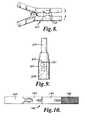
- FIG. 8is a side view of a tool for detaching the connector from the insertion needle.
- FIG. 9is a side view of the connector for use with the tool of FIG. 8 .
- FIG. 10is a sectional view of a two-piece connector attaching a mesh support structure.
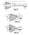
- FIG. 11is a sectional view of a needle in proximity to the connector.
- FIG. 12is a sectional view of a collar being placed on the insertion needle.
- FIG. 13is a sectional view of the collar dislodging the connector from the insertion needle.
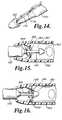
- FIG. 14is a side view of an insertion needle having a channel formed therein.
- FIG. 15is a sectional view of connector legs on the collar.
- FIG. 16is a sectional view of the collar moved against the tip of the insertion needle.
- FIG. 17is a sectional view of the connector disengaged from the insertion needle.
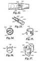
- FIG. 18is a perspective view of an alternative configuration of the collar having an indent formed therein.
- FIG. 19is a sectional view of the collar of FIG. 18 .
- FIG. 20is a side view of the collar of FIG. 18 .
- FIG. 21is a sectional view of an alternative tip configuration.
- FIG. 22is a sectional view of a collar engaging the alternative tip configuration of FIG. 21 .
- FIG. 23is a sectional view of another configuration of the collar with a lip formed therein.
- FIG. 24is a sectional view of the collar of FIG. 23 adjacent to an insertion needle tip.
- FIG. 25is a perspective view of an alternative connector having a pair of slots formed therein.
- FIG. 26is side view of an alternate mechanism for attaching the connector to the mesh assembly with a barb and collar configuration.
- FIG. 27is a side view of an alternate configuration for attaching the connector to the mesh assembly with a pin.
- FIG. 28is a side view of an alternative configuration for attaching the connector to the mesh assembly with an adaptor.
- FIG. 29is a perspective view of a C-shaped leg extending from an inner wall of the connector.
- FIG. 30is a perspective view of the C-shaped leg with reinforcing ribs.
- FIG. 31is a perspective view of a support shelf used in conjunction with the C-shaped leg.
- FIG. 32is a side view of the connector showing an aperture formed therein.
- FIG. 33is a perspective sectional view of another configuration of the connector.
- FIG. 34is a sectional view of the connector of FIG. 33 .
- FIG. 35is a perspective view of an alternate configuration for the C-shaped leg.
- FIG. 36is top view of the C-shaped leg of FIG. 35 .
- FIG. 37is a perspective view of the C-shaped leg of FIG. 35 with a slot formed between the legs thereof.
- FIG. 38is a top view of the C-shaped leg of FIG. 37 in a wide opened configuration.
- FIG. 39is a top view of the C-shaped leg of FIG. 37 in a relaxed configuration.
- FIG. 40is a top view of the C-shaped leg of FIG. 37 in an expanded configuration.
- FIG. 41is a perspective view of an alternate configuration of the C-shaped leg.
- the inventionis directed to several devices and techniques for use in positioning mesh within a patient (male or female) that are discussed in more detail below.
- a conventional technique used for treatment of vaginal wall prolapseis with a mesh support structure having four legs extending therefrom.
- this surgical procedureis performed using a kit that not only includes the mesh support structure but also four insertion needles that are used for positioning the mesh support structure within the patient. Similar kits have also been used to treat urinary stress incontinence.
- a prior technique for attaching the insertion needle to the meshutilizes a snapping or locking mechanism.
- the friction fit mechanismtypically requires a relatively large lineal force of greater than 10 pounds to detach the insertion needle from the mesh support structure.
- this embodiment of the inventionenables the needle to be readily detached from the connector, this embodiment enables a mesh support structure having four legs to be inserted using two insertion needles.
- the insertion needles used in this embodimentmay be identified as right and left.
- the insertion needleseach include a connector that enables the insertion needles to be readily detached from the mesh support structure.
- Each of the insertion needlesis used with a connector that allows for quick detachment from the mesh support structure either through a quick detachment geometry built into the insertion needle or the connector, or through the use of a tool that aides in the quick removal of the connector from the insertion needle.
- the needle 100includes at least one J-shaped slot 102 formed therein, as illustrated in FIGS. 1-3 .
- the connector 104includes an inwardly directed extension 106 that extends from a wall of the aperture 108 through which the needle 100 is inserted, as illustrated in FIG. 4 .
- the inwardly directed extension 106has a width that is slightly smaller than a width of the J-shaped slot 102 .
- the connector 104When connecting the connector 104 to the insertion needle 100 , the connector 104 is moved towards the insertion needle 100 , as illustrated by arrow 110 in FIG. 5 , until the insertion needle 100 extends into the connector 104 . As the insertion needle 100 is inserted into the connector 104 , the inwardly directed extension 106 slides in the J-shaped slot 102 until the inwardly directed extension 106 contacts the bottom of the J-shaped slot 102 . At that time, the connector 104 is rotated with respect to the insertion needle 100 , as illustrated by arrow 112 in FIG. 6 . The connector 104 is then pulled away from the insertion needle 100 , as illustrated by arrow 114 in FIG. 7 .
- the connector 104is thereby attached to the insertion needle 100 such that lineal pulling and pushing of the insertion needle 100 enables the connector 104 and the attached portion of the mesh support structure to be pulled through the patient. Once the mesh support structure is pulled to a desired location, the attachment process set forth above is reversed to detach the connector 104 from the insertion needle 100 .
- a tool 120is provided to detach the connector 122 from the insertion needle 124 .
- At least one leg 126is provided on an inner surface of the connector 122 , as illustrated in FIG. 9 .
- the leg 126engages a ridge 128 extending from the insertion needle 124 and thereby retains the connector 122 on the insertion needle 124 .
- the legs 126may be positioned on opposite sides of the connector 122 such that pushing opposite legs 126 towards each other enables the connector 122 to be released from the insertion needle 124 .
- Each leg 126may be positioned proximate an opening 130 that extends through a wall of the connector 122 .
- Each opening 130is adapted to receive a tab 132 on a pliers-like tool 120 . When the tab 132 engages the leg 126 , the connector 122 may be removed from the needle 124 .
- the right and left insertion needlesare inserted into the patient using conventionally known techniques.
- the right and left insertion needlesare then connected to two of the legs extending from the mesh support structure and the insertion needles are withdrawn from the patient to pull each of the legs through the associated obturator.
- Each of the connectorsis then disengaged to separate the insertion needles from the mesh support structure, the process is then repeated to insert the other two legs into the desired location in the patient.
- a two-piece connector 140As an alternative to using a one-piece connector that is discussed above, it is also possible to use a two-piece connector 140 , as illustrated in FIG. 10 .
- a proximal connector portion 142is attached to the insertion needle 144 and a distal connector portion 146 is attached to the mesh support structure 148 .
- the proximal connector portion 142 and the distal connector portion 144engage each other to attach the insertion needle to the connector 140 such as by using one of the connection methods described herein.
- Another configuration for removably attaching the connector to the needleincludes an insertion needle 150 with a reduced diameter section 152 that is adjacent to but offset from a tip 154 of the insertion needle 150 , as illustrated in FIG. 11 .
- the reduced diameter section 152may have a length of about 0.75 inches.
- the connector 156includes at least one inwardly directed tab 158 that engages a lip 160 where the reduced diameter section 152 and the tip 154 intersect to retain the connector 156 on the insertion needle 150 .
- a C-shaped collar 162is placed over the reduced diameter section 152 , as illustrated in FIG. 12 .
- the collar 162is formed with a length based upon the length of the reduced diameter section 152 and the distance to the tab 158 from the front of the connector 156 .
- the collar 162is then urged towards the tip 154 , as illustrated in FIG. 13 .
- the collar 162thereby contacts the at least one inwardly directed tab 158 and urges the inwardly directed tab 158 outward.
- the inwardly directed tab 158no longer engages the lip 160 , which allows the connector 156 to be removed from the insertion needle 150 .
- the collar 162may be removed from the reduced diameter section 152 and the insertion needle 150 may be reused. Alternatively, the collar 162 may be permanently left on the insertion needle 150 .
- a channel 170may be formed in the insertion needle 172 , as illustrated in FIG. 14 .
- the channel 170would receive an arm 174 or other device that extends to proximate the lip 160 .
- the arm 174may be pivoted to urge the inwardly directed tab outward.
- a pump action mechanismis provided to detach the connector 180 from the insertion needle 182 , as illustrated in FIGS. 15-17 .
- the collar 184is formed with a length that may be less than a length of the reduced diameter region 186 . This configuration enables the collar 184 to slide with respect to the insertion needle 182 .
- the connector arms 188engage a lip 190 where the tip 192 and the reduced diameter region 186 intersect.
- the connector 180is urged away from the distal end of the insertion needle 182 , as illustrated in FIG. 15 .
- the connector 180is moved away from the insertion needle 182 .
- the lip 190limits movement of the collar 184 , as illustrated in FIG. 16 .
- the continued pulling of the connector 180 away from the insertion needle 182causes the connector arms 188 to move past the lip 190 to release the connector 180 from the insertion needle 182 , as illustrated in FIG. 17 .
- the collar 184may include a ridge 196 or indent on an outer surface thereof, as illustrated in FIGS. 18-20 , to assist in the connector arms 188 retaining the collar 184 during movement.
- a lip 200may also include an angled surface 202 that forms a pocket, as illustrated in FIGS. 21-22 .
- the angled surface 202may substantially correspond with an angled surface 204 on a distal end 206 of the collar 208 . This configuration of the insertion needle 210 and collar 208 enhances the ability to provide a smooth transition between the collar 208 and the lip 200 even if they are not in exact alignment.
- Yet another configuration of the collar 212includes a lip 214 proximate a distal end 216 thereof, as illustrated in FIGS. 23-24 .
- the lip 214extends over a portion of the tip 218 when the connector is being removed from the insertion needle 220 to enhance the ability to remove the connector from the insertion needle 220 .
- Another configuration of the connector 230has at least one slit 232 in the distal end 234 thereof, as illustrated in FIG. 25 .
- the connector 230When it is desired to remove the connector 230 from the insertion needle, the connector 230 is pivoted with respect to the insertion needle, as indicated by arrow 236 . At least one slit 232 enables sides 238 of the connector 230 to be urged apart from each other, which thereby releases the connector 230 from the insertion needle.
- the above concernsmay be addressed by attaching the mesh assembly to a proximal end of the connector.
- an outer sheath 254 on the mesh assembly 250is rolled so that a distal end 256 of the sheath 254 is generally tubular, as illustrated in FIG. 26 .
- the distal end 256 of the sheath 254is extended through a collar 258 and a barbed adaptor 260 is inserted into the sheath 254 .
- the collar 258is moved over the barbed adaptor 260 to retain the adaptor 260 in a fixed position with respect to the mesh assembly 250 .
- the adaptor 260may be then secured to the connector 252 using a snap feature 262 .
- An alternative technique for attaching a mesh assembly 270 to a connector 272includes an aperture 274 in the connector 272 that is oriented substantially transverse to a central axis 276 of the connector 272 , as illustrated in FIG. 27 .
- a corresponding aperture 278would be formed in the mesh assembly 270 .
- the mesh assembly 270is inserted into the proximal end of the connector 272 until the aperture 274 in the connector 272 is generally aligned with the aperture 278 in the mesh assembly 270 .
- a pin 280is then inserted through the connector and mesh assembly apertures 274 , 278 to retain the connector 272 and mesh assembly 270 in a fixed position with respect to each other.
- FIG. 28Another technique for attaching a mesh assembly 290 to a connector 292 would be through the use of an adaptor 294 , as illustrated in FIG. 28 .
- a proximal end 296 of the adaptor 294has an eyelet 298 extending therethrough that is adapted to receive the mesh assembly 290 .
- a distal end 300 of the adapter 294is then attached to the connector 292 such as through welding or a snap feature.
- the distal end 300 of the adapter 294may have a threaded outer surface. The threaded outer surface would engage a threaded inner surface in the connector 292 to removably attach the mesh assembly 290 to the connector 292 .
- the connector 320may include a C-shaped connector 322 that extends inwardly from a wall thereof, as illustrated in FIG. 29 .
- one or more ribs 324may extend from the C-shaped connector 322 to the wall of the connector 320 , as illustrated in FIG. 30 .
- the walls of the C-shaped connector 322are urged apart from each other to allow the needle 326 to pass therethrough. Once the tip of the needle 326 passes the C-shaped connector 322 , the C-shaped connector 322 engages the lip 328 and thereby prevents the connector 320 from being removed from the insertion needle 326 .
- Another technique to reduce the potential of the C-shaped connector 322 being damaged during insertion of the needle 326 into the connector 320is through a support shelf 330 that extends from an opposite wall of the connector 320 , as illustrated in FIG. 31 . Forces generated during the insertion of the needle 326 into the connector 320 would thereby be distributed over both the C-shaped connector 322 and the support shelf 330 .
- the wall of the connector 320 above an open end of the C-shaped connector 322may have an aperture 332 formed therein, as illustrated in FIGS. 32-33 .
- a tool(not shown) having a thin blade such as a screwdriver is inserted into the aperture 332 to cause the legs of the C-shaped connector 322 to more apart from each other to thereby release the needle 326 .
- an extension 334may be provided on the end of the C-shaped connector 322 to increase the surface areas that the tool contacts, as illustrated in FIGS. 33-34 .
- the locking mechanism 340may have a generally circular shape having an opening 342 at one side thereof, as illustrated in FIGS. 35-36 .
- a first extension 344 and a second extension 346extend from opposite ends of the locking mechanism 340 .
- An end of the first extension 344extends beyond an end of the second extension 346 .
- first and second extensions 344 , 346may be necessary to increase the flexibility of the first and second extensions 344 , 346 by providing a slot 350 therebetween, as illustrated in FIG. 37 .
- a person of skill in the artwill appreciate that the deeper the slot 350 , the more flexibility that is imparted to the first and second extensions 344 , 346 .
- the first extension 344 and the second extension 346may each have a tab 352 extending outwardly therefrom proximate an end thereof. Since the first extension 344 is offset from the second extension 346 , urging the tabs 352 towards each other causes a diameter of the locking mechanism 340 to increase and thereby allows the locking mechanism 340 to release the needle (not shown). When removing the locking mechanism 340 , it may be necessary to urge the tabs 352 pas
- a locking mechanism 360which is illustrated in FIG. 41 , includes a central extension 362 that is positioned between an upper extension 364 and a lower extension 366 . Ends of the upper and lower extension 364 , 366 extend beyond an end of the central extension 362 .
- the central, upper and lower extensions 362 , 364 , 366each have a tab 368 extending outwardly therefrom proximate an end thereof. Since the central extension 362 is offset from the upper and lower extensions 364 , 366 , urging the tab 368 on the central extension 362 towards the tabs 368 on the upper and lower extensions 364 , 366 causes a diameter of the locking mechanism 360 to increase and thereby allows the locking mechanism 360 to release the needle (not shown).
- this configuration of the locking mechanism 360has greater symmetry than the embodiment of the locking mechanism disclosed in FIG. 35 and thereby may reduce twisting of the locking mechanism 360 during operation.
- a technique for attaching the mesh assembly to the connectoris directed to molding the connector over an end of the mesh assembly, such as for use with the connector illustrated in FIGS. 27-29 .
- the connector moldis formed with an opening that is adapted to receive the end of the mesh assembly.
- the inventionrelates to molding a connector over the end of the mesh assembly and then attaching the connector to the connector.
Landscapes
- Health & Medical Sciences (AREA)
- Life Sciences & Earth Sciences (AREA)
- Surgery (AREA)
- Heart & Thoracic Surgery (AREA)
- Engineering & Computer Science (AREA)
- Biomedical Technology (AREA)
- Nuclear Medicine, Radiotherapy & Molecular Imaging (AREA)
- Medical Informatics (AREA)
- Molecular Biology (AREA)
- Animal Behavior & Ethology (AREA)
- General Health & Medical Sciences (AREA)
- Public Health (AREA)
- Veterinary Medicine (AREA)
- Infusion, Injection, And Reservoir Apparatuses (AREA)
- Surgical Instruments (AREA)
Abstract
Description
Claims (9)
Priority Applications (1)
| Application Number | Priority Date | Filing Date | Title |
|---|---|---|---|
| US13/034,842US9877717B2 (en) | 2005-10-05 | 2011-02-25 | Connector for mesh support insertion |
Applications Claiming Priority (3)
| Application Number | Priority Date | Filing Date | Title |
|---|---|---|---|
| US72433205P | 2005-10-05 | 2005-10-05 | |
| US11/537,891US7909753B1 (en) | 2005-10-05 | 2006-10-02 | Connector for mesh support insertion |
| US13/034,842US9877717B2 (en) | 2005-10-05 | 2011-02-25 | Connector for mesh support insertion |
Related Parent Applications (1)
| Application Number | Title | Priority Date | Filing Date |
|---|---|---|---|
| US11/537,891ContinuationUS7909753B1 (en) | 2005-10-05 | 2006-10-02 | Connector for mesh support insertion |
Publications (2)
| Publication Number | Publication Date |
|---|---|
| US20110144418A1 US20110144418A1 (en) | 2011-06-16 |
| US9877717B2true US9877717B2 (en) | 2018-01-30 |
Family
ID=43741721
Family Applications (2)
| Application Number | Title | Priority Date | Filing Date |
|---|---|---|---|
| US11/537,891Expired - Fee RelatedUS7909753B1 (en) | 2005-10-05 | 2006-10-02 | Connector for mesh support insertion |
| US13/034,842Expired - Fee RelatedUS9877717B2 (en) | 2005-10-05 | 2011-02-25 | Connector for mesh support insertion |
Family Applications Before (1)
| Application Number | Title | Priority Date | Filing Date |
|---|---|---|---|
| US11/537,891Expired - Fee RelatedUS7909753B1 (en) | 2005-10-05 | 2006-10-02 | Connector for mesh support insertion |
Country Status (1)
| Country | Link |
|---|---|
| US (2) | US7909753B1 (en) |
Families Citing this family (6)
| Publication number | Priority date | Publication date | Assignee | Title |
|---|---|---|---|---|
| US6641525B2 (en)* | 2001-01-23 | 2003-11-04 | Ams Research Corporation | Sling assembly with secure and convenient attachment |
| US7909753B1 (en)* | 2005-10-05 | 2011-03-22 | Ams Research Corporation | Connector for mesh support insertion |
| EP2194913A1 (en) | 2007-09-21 | 2010-06-16 | AMS Research Corporation | Pelvic floor treatments and related tools and implants |
| US9393091B2 (en)* | 2009-12-31 | 2016-07-19 | Astora Women's Health, Llc | Suture-less tissue fixation for implantable device |
| WO2014162422A1 (en)* | 2013-04-01 | 2014-10-09 | テルモ株式会社 | Puncture needle assembly |
| CN113116425B (en)* | 2019-12-31 | 2024-11-19 | 杭州德晋医疗科技有限公司 | Valve Suture Devices |
Citations (21)
| Publication number | Priority date | Publication date | Assignee | Title |
|---|---|---|---|---|
| US4683883A (en)* | 1985-04-30 | 1987-08-04 | Hemex Scientific, Inc. | Two-piece heart valve holder/rotator |
| US20020099259A1 (en)* | 2001-01-23 | 2002-07-25 | Anderson Kimberly A. | Surgical instrument and method |
| US20030023138A1 (en) | 1999-06-09 | 2003-01-30 | Luscombe Brian H. | Surgical instrument and method for treating female urinary incontinence |
| US20030036676A1 (en) | 2000-01-21 | 2003-02-20 | Sofradim Production | Percutaneous device and method for treating urinary stress incontinence in women using a sub-urethral tape |
| US20030171644A1 (en)* | 2002-03-07 | 2003-09-11 | Anderson Kimberly A. | Transobturator surgical articles and methods |
| US20030212305A1 (en) | 2002-03-07 | 2003-11-13 | Anderson Kimberly A. | Transobturator surgical articles and methods |
| US20040087970A1 (en)* | 2001-03-09 | 2004-05-06 | Chu Michael S.H. | Systems, methods and devices relating to delivery of medical implants |
| US6884212B2 (en) | 2000-09-07 | 2005-04-26 | Ams Research Corporation | Implantable article and method |
| US20050256366A1 (en) | 2004-05-06 | 2005-11-17 | Chu Michael S H | Systems and methods employing a push tube for delivering a urethral sling |
| US7025772B2 (en) | 2001-03-09 | 2006-04-11 | Scimed Life Systems, Inc. | System for implanting an implant and method thereof |
| US20060089525A1 (en)* | 2004-06-14 | 2006-04-27 | Boston Scientific Scimed, Inc. | Systems, methods and devices relating to implantable supportive slings |
| WO2007149593A2 (en) | 2006-06-22 | 2007-12-27 | Ams Research Corporation | Adjustable tension incontinence sling assemblies |
| US20080103351A1 (en) | 2001-07-27 | 2008-05-01 | Montpetit Karen P | Pelvic health implants and methods |
| US20080207989A1 (en) | 2005-08-29 | 2008-08-28 | Ams Research Corporation | System For Positioning Support Mesh in a Patient |
| US20090012592A1 (en) | 2006-07-10 | 2009-01-08 | Ams Research Corporation | Tissue anchor |
| US20090240104A1 (en) | 2007-10-26 | 2009-09-24 | Ams Research Corporation | Surgical Articles and Methods for Treating Pelvic Conditions |
| US20100105979A1 (en) | 2008-10-27 | 2010-04-29 | Ams Research Corporation | Surgical Needle and Anchor System with Retractable Features |
| WO2010093421A2 (en) | 2009-02-10 | 2010-08-19 | Ams Research Corporation | Surgical articles and methods for treating urinary incontinence |
| US20100256442A1 (en) | 2006-02-16 | 2010-10-07 | Ogdahl Jason W | Surgical Articles and Methods for Treating Pelvic Conditions |
| US20110034759A1 (en) | 2006-10-26 | 2011-02-10 | Ogdahl Jason W | Surgical articles and methods for treating pelvic conditions |
| US7909753B1 (en) | 2005-10-05 | 2011-03-22 | Ams Research Corporation | Connector for mesh support insertion |
- 2006
- 2006-10-02USUS11/537,891patent/US7909753B1/ennot_activeExpired - Fee Related
- 2011
- 2011-02-25USUS13/034,842patent/US9877717B2/ennot_activeExpired - Fee Related
Patent Citations (24)
| Publication number | Priority date | Publication date | Assignee | Title |
|---|---|---|---|---|
| US4683883A (en)* | 1985-04-30 | 1987-08-04 | Hemex Scientific, Inc. | Two-piece heart valve holder/rotator |
| US20030023138A1 (en) | 1999-06-09 | 2003-01-30 | Luscombe Brian H. | Surgical instrument and method for treating female urinary incontinence |
| US20030036676A1 (en) | 2000-01-21 | 2003-02-20 | Sofradim Production | Percutaneous device and method for treating urinary stress incontinence in women using a sub-urethral tape |
| US6884212B2 (en) | 2000-09-07 | 2005-04-26 | Ams Research Corporation | Implantable article and method |
| US20020099259A1 (en)* | 2001-01-23 | 2002-07-25 | Anderson Kimberly A. | Surgical instrument and method |
| US7025772B2 (en) | 2001-03-09 | 2006-04-11 | Scimed Life Systems, Inc. | System for implanting an implant and method thereof |
| US20040087970A1 (en)* | 2001-03-09 | 2004-05-06 | Chu Michael S.H. | Systems, methods and devices relating to delivery of medical implants |
| US7407480B2 (en) | 2001-07-27 | 2008-08-05 | Ams Research Corporation | Method and apparatus for correction of urinary and gynecological pathologies, including treatment of incontinence cystocele |
| US20080140218A1 (en) | 2001-07-27 | 2008-06-12 | Ams Research Corporation | Pelvic health implants and methods |
| US20080103351A1 (en) | 2001-07-27 | 2008-05-01 | Montpetit Karen P | Pelvic health implants and methods |
| US20030171644A1 (en)* | 2002-03-07 | 2003-09-11 | Anderson Kimberly A. | Transobturator surgical articles and methods |
| US6911003B2 (en) | 2002-03-07 | 2005-06-28 | Ams Research Corporation | Transobturator surgical articles and methods |
| US20030212305A1 (en) | 2002-03-07 | 2003-11-13 | Anderson Kimberly A. | Transobturator surgical articles and methods |
| US20050256366A1 (en) | 2004-05-06 | 2005-11-17 | Chu Michael S H | Systems and methods employing a push tube for delivering a urethral sling |
| US20060089525A1 (en)* | 2004-06-14 | 2006-04-27 | Boston Scientific Scimed, Inc. | Systems, methods and devices relating to implantable supportive slings |
| US20080207989A1 (en) | 2005-08-29 | 2008-08-28 | Ams Research Corporation | System For Positioning Support Mesh in a Patient |
| US7909753B1 (en) | 2005-10-05 | 2011-03-22 | Ams Research Corporation | Connector for mesh support insertion |
| US20100256442A1 (en) | 2006-02-16 | 2010-10-07 | Ogdahl Jason W | Surgical Articles and Methods for Treating Pelvic Conditions |
| WO2007149593A2 (en) | 2006-06-22 | 2007-12-27 | Ams Research Corporation | Adjustable tension incontinence sling assemblies |
| US20090012592A1 (en) | 2006-07-10 | 2009-01-08 | Ams Research Corporation | Tissue anchor |
| US20110034759A1 (en) | 2006-10-26 | 2011-02-10 | Ogdahl Jason W | Surgical articles and methods for treating pelvic conditions |
| US20090240104A1 (en) | 2007-10-26 | 2009-09-24 | Ams Research Corporation | Surgical Articles and Methods for Treating Pelvic Conditions |
| US20100105979A1 (en) | 2008-10-27 | 2010-04-29 | Ams Research Corporation | Surgical Needle and Anchor System with Retractable Features |
| WO2010093421A2 (en) | 2009-02-10 | 2010-08-19 | Ams Research Corporation | Surgical articles and methods for treating urinary incontinence |
Also Published As
| Publication number | Publication date |
|---|---|
| US7909753B1 (en) | 2011-03-22 |
| US20110144418A1 (en) | 2011-06-16 |
Similar Documents
| Publication | Publication Date | Title |
|---|---|---|
| JP7364732B2 (en) | Reloadable hemostasis clip device with an engagement part on the sleeve | |
| AU2019212055B2 (en) | Hemostasis clip | |
| US5328077A (en) | Method and apparatus for treating female urinary incontinence | |
| US9888912B2 (en) | Collapsible tissue anchor device and method | |
| US8944990B2 (en) | Surgical needle and anchor system with retractable features | |
| US9877717B2 (en) | Connector for mesh support insertion | |
| EP1965726B1 (en) | Stress urinary incontinence implant | |
| US8277467B2 (en) | Anastomosis device configurations and methods | |
| US8303544B2 (en) | Cystotomy catheter capture device | |
| CN105559946B (en) | Biceps tenodesis anchor implant | |
| CN100589778C (en) | Sub-urethral support assembly for treating female stress urinary incontinence | |
| EP2380509A2 (en) | Through the scope tension member release clip | |
| JP2009528851A (en) | Apparatus and method for inserting an implant | |
| EP1267730A2 (en) | Devices and methods for treating e.g. urinary stress incontinence | |
| US20100241105A1 (en) | System for introducing implants | |
| US11413128B2 (en) | Devices and methods for fixation of bodily implants | |
| AU2015203295A1 (en) | Surgical needle and anchor system with retractable features | |
| AU2013203756A1 (en) | Apparatus and method for introducing implants |
Legal Events
| Date | Code | Title | Description |
|---|---|---|---|
| AS | Assignment | Owner name:AMS RESEARCH CORPORATION, MINNESOTA Free format text:ASSIGNMENT OF ASSIGNORS INTEREST;ASSIGNORS:OGDAHL, JASON WESTRUM;OTTE, JOHN F.;BOUCHIER, MARK S.;AND OTHERS;SIGNING DATES FROM 20060929 TO 20061002;REEL/FRAME:025863/0355 | |
| AS | Assignment | Owner name:MORGAN STANLEY SENIOR FUNDING, INC., AS ADMINISTRA Free format text:SECURITY AGREEMENT;ASSIGNOR:AMS RESEARCH CORPORATION;REEL/FRAME:026632/0535 Effective date:20110617 | |
| AS | Assignment | Owner name:AMS RESEARCH CORPORATION, MINNESOTA Free format text:RELEASE OF PATENT SECURITY INTEREST;ASSIGNOR:MORGAN STANLEY SENIOR FUNDING, INC., AS ADMINISTRATIVE AGENT;REEL/FRAME:032380/0053 Effective date:20140228 | |
| AS | Assignment | Owner name:DEUTSCHE BANK AG NEW YORK BRANCH, AS COLLATERAL AGENT, NEW YORK Free format text:GRANT OF SECURITY INTEREST IN PATENTS;ASSIGNORS:ENDO PHARMACEUTICALS SOLUTIONS, INC.;ENDO PHARMACEUTICALS, INC.;AMS RESEARCH CORPORATION;AND OTHERS;REEL/FRAME:032491/0440 Effective date:20140228 Owner name:DEUTSCHE BANK AG NEW YORK BRANCH, AS COLLATERAL AG Free format text:GRANT OF SECURITY INTEREST IN PATENTS;ASSIGNORS:ENDO PHARMACEUTICALS SOLUTIONS, INC.;ENDO PHARMACEUTICALS, INC.;AMS RESEARCH CORPORATION;AND OTHERS;REEL/FRAME:032491/0440 Effective date:20140228 | |
| AS | Assignment | Owner name:LASERSCOPE, CALIFORNIA Free format text:RELEASE BY SECURED PARTY;ASSIGNOR:DEUTSCHE BANK AG NEW YORK BRANCH;REEL/FRAME:036285/0146 Effective date:20150803 Owner name:AMERICAN MEDICAL SYSTEMS, LLC, MINNESOTA Free format text:RELEASE BY SECURED PARTY;ASSIGNOR:DEUTSCHE BANK AG NEW YORK BRANCH;REEL/FRAME:036285/0146 Effective date:20150803 Owner name:AMS RESEARCH, LLC, MINNESOTA Free format text:RELEASE BY SECURED PARTY;ASSIGNOR:DEUTSCHE BANK AG NEW YORK BRANCH;REEL/FRAME:036285/0146 Effective date:20150803 | |
| AS | Assignment | Owner name:AMS RESEARCH, LLC, MINNESOTA Free format text:CHANGE OF NAME;ASSIGNOR:AMS RESEARCH CORPATION;REEL/FRAME:037300/0199 Effective date:20141217 | |
| AS | Assignment | Owner name:ASTORA WOMEN'S HEALTH, LLC, MINNESOTA Free format text:CHANGE OF NAME;ASSIGNOR:APHRODITE WOMEN'S HEALTH, LLC;REEL/FRAME:037473/0919 Effective date:20150929 Owner name:APHRODITE WOMEN'S HEALTH, LLC, MINNESOTA Free format text:ASSIGNMENT OF ASSIGNORS INTEREST;ASSIGNOR:AMS RESEARCH, LLC;REEL/FRAME:037473/0745 Effective date:20150227 | |
| AS | Assignment | Owner name:AMS RESEARCH, LLC, MINNESOTA Free format text:CORRECTIVE ASSIGNMENT TO CORRECT THE CONVEYING PARTY DATA; PREVIOUSLY RECORDED ON REEL 037300 FRAME 0199. ASSIGNOR(S) HEREBY CONFIRMS THE CHANGE OF NAME;ASSIGNOR:AMS RESEARCH CORPORATION;REEL/FRAME:037916/0028 Effective date:20141217 | |
| AS | Assignment | Owner name:WILMINGTON TRUST, NATIONAL ASSOCIATION, AS COLLATERAL TRUSTEE, DELAWARE Free format text:SECURITY INTEREST;ASSIGNOR:ASTORA WOMEN'S HEALTH, LLC;REEL/FRAME:042743/0278 Effective date:20170427 Owner name:WILMINGTON TRUST, NATIONAL ASSOCIATION, AS COLLATE Free format text:SECURITY INTEREST;ASSIGNOR:ASTORA WOMEN'S HEALTH, LLC;REEL/FRAME:042743/0278 Effective date:20170427 | |
| AS | Assignment | Owner name:BOSTON SCIENTIFIC SCIMED, INC., MINNESOTA Free format text:ASSIGNMENT OF ASSIGNORS INTEREST;ASSIGNOR:BOSTON SCIENTIFIC CORPORATION;REEL/FRAME:043778/0167 Effective date:20161222 Owner name:BOSTON SCIENTIFIC CORPORATION, MASSACHUSETTS Free format text:ASSIGNMENT OF ASSIGNORS INTEREST;ASSIGNORS:ASTORA WOMEN'S HEALTH, LLC;ENDO HEALTH SOLUTIONS INC.;ASTORA WOMEN'S HEALTH HOLDINGS, LLC;REEL/FRAME:043777/0895 Effective date:20161222 | |
| STCF | Information on status: patent grant | Free format text:PATENTED CASE | |
| FEPP | Fee payment procedure | Free format text:MAINTENANCE FEE REMINDER MAILED (ORIGINAL EVENT CODE: REM.); ENTITY STATUS OF PATENT OWNER: LARGE ENTITY | |
| LAPS | Lapse for failure to pay maintenance fees | Free format text:PATENT EXPIRED FOR FAILURE TO PAY MAINTENANCE FEES (ORIGINAL EVENT CODE: EXP.); ENTITY STATUS OF PATENT OWNER: LARGE ENTITY | |
| STCH | Information on status: patent discontinuation | Free format text:PATENT EXPIRED DUE TO NONPAYMENT OF MAINTENANCE FEES UNDER 37 CFR 1.362 | |
| FP | Lapsed due to failure to pay maintenance fee | Effective date:20220130 | |
| AS | Assignment | Owner name:VINTAGE PHARMACEUTICALS, LLC, NEW YORK Free format text:RELEASE BY SECURED PARTY;ASSIGNOR:WILMINGTON TRUST, NATIONAL ASSOCIATION;REEL/FRAME:067240/0001 Effective date:20240423 Owner name:SLATE PHARMACEUTICALS, LLC, PENNSYLVANIA Free format text:RELEASE BY SECURED PARTY;ASSIGNOR:WILMINGTON TRUST, NATIONAL ASSOCIATION;REEL/FRAME:067240/0001 Effective date:20240423 Owner name:QUARTZ SPECIALTY PHARMACEUTICALS, LLC, NEW YORK Free format text:RELEASE BY SECURED PARTY;ASSIGNOR:WILMINGTON TRUST, NATIONAL ASSOCIATION;REEL/FRAME:067240/0001 Effective date:20240423 Owner name:PAR STERILE PRODUCTS, LLC (FORMERLY KNOWN AS JHP PHARMACEUTICALS, LLC), NEW YORK Free format text:RELEASE BY SECURED PARTY;ASSIGNOR:WILMINGTON TRUST, NATIONAL ASSOCIATION;REEL/FRAME:067240/0001 Effective date:20240423 Owner name:PAR PHARMACEUTICAL, INC., NEW YORK Free format text:RELEASE BY SECURED PARTY;ASSIGNOR:WILMINGTON TRUST, NATIONAL ASSOCIATION;REEL/FRAME:067240/0001 Effective date:20240423 Owner name:GENERICS INTERNATIONAL (US), INC., NEW YORK Free format text:RELEASE BY SECURED PARTY;ASSIGNOR:WILMINGTON TRUST, NATIONAL ASSOCIATION;REEL/FRAME:067240/0001 Effective date:20240423 Owner name:GENERICS BIDCO I, LLC, NEW YORK Free format text:RELEASE BY SECURED PARTY;ASSIGNOR:WILMINGTON TRUST, NATIONAL ASSOCIATION;REEL/FRAME:067240/0001 Effective date:20240423 Owner name:ENDO PHARMACEUTICALS SOLUTIONS INC. (FORMERLY KNOWN AS INDEVUS PHARMACEUTICALS, INC.), PENNSYLVANIA Free format text:RELEASE BY SECURED PARTY;ASSIGNOR:WILMINGTON TRUST, NATIONAL ASSOCIATION;REEL/FRAME:067240/0001 Effective date:20240423 Owner name:ENDO PHARMACEUTICALS INC., PENNSYLVANIA Free format text:RELEASE BY SECURED PARTY;ASSIGNOR:WILMINGTON TRUST, NATIONAL ASSOCIATION;REEL/FRAME:067240/0001 Effective date:20240423 Owner name:ENDO GENERIC HOLDINGS, INC. (FORMERLY KNOWN AS PAR PHARMACEUTICALS COMPANIES, INC.), PENNSYLVANIA Free format text:RELEASE BY SECURED PARTY;ASSIGNOR:WILMINGTON TRUST, NATIONAL ASSOCIATION;REEL/FRAME:067240/0001 Effective date:20240423 Owner name:DAVA PHARMACEUTICALS, LLC, NEW YORK Free format text:RELEASE BY SECURED PARTY;ASSIGNOR:WILMINGTON TRUST, NATIONAL ASSOCIATION;REEL/FRAME:067240/0001 Effective date:20240423 Owner name:DAVA INTERNATIONAL, LLC, PENNSYLVANIA Free format text:RELEASE BY SECURED PARTY;ASSIGNOR:WILMINGTON TRUST, NATIONAL ASSOCIATION;REEL/FRAME:067240/0001 Effective date:20240423 Owner name:BIOSPECIFICS TECHNOLOGIES LLC, PENNSYLVANIA Free format text:RELEASE BY SECURED PARTY;ASSIGNOR:WILMINGTON TRUST, NATIONAL ASSOCIATION;REEL/FRAME:067240/0001 Effective date:20240423 Owner name:BIOSPECIFICS TECHNOLOGIES CORP., PENNSYLVANIA Free format text:RELEASE BY SECURED PARTY;ASSIGNOR:WILMINGTON TRUST, NATIONAL ASSOCIATION;REEL/FRAME:067240/0001 Effective date:20240423 Owner name:AUXILIUM US HOLDINGS, LLC, PENNSYLVANIA Free format text:RELEASE BY SECURED PARTY;ASSIGNOR:WILMINGTON TRUST, NATIONAL ASSOCIATION;REEL/FRAME:067240/0001 Effective date:20240423 Owner name:AUXILIUM PHARMACEUTICALS, LLC, PENNSYLVANIA Free format text:RELEASE BY SECURED PARTY;ASSIGNOR:WILMINGTON TRUST, NATIONAL ASSOCIATION;REEL/FRAME:067240/0001 Effective date:20240423 Owner name:ASTORA WOMEN'S HEALTH LLC, PENNSYLVANIA Free format text:RELEASE BY SECURED PARTY;ASSIGNOR:WILMINGTON TRUST, NATIONAL ASSOCIATION;REEL/FRAME:067240/0001 Effective date:20240423 Owner name:ASTORA WOMEN'S HEALTH HOLDINGS, LLC, MINNESOTA Free format text:RELEASE BY SECURED PARTY;ASSIGNOR:WILMINGTON TRUST, NATIONAL ASSOCIATION;REEL/FRAME:067240/0001 Effective date:20240423 Owner name:ACTIENT PHARMACEUTICALS LLC, PENNSYLVANIA Free format text:RELEASE BY SECURED PARTY;ASSIGNOR:WILMINGTON TRUST, NATIONAL ASSOCIATION;REEL/FRAME:067240/0001 Effective date:20240423 |