US9874749B2 - Virtual and augmented reality systems and methods - Google Patents
Virtual and augmented reality systems and methodsDownload PDFInfo
- Publication number
- US9874749B2 US9874749B2US14/641,376US201514641376AUS9874749B2US 9874749 B2US9874749 B2US 9874749B2US 201514641376 AUS201514641376 AUS 201514641376AUS 9874749 B2US9874749 B2US 9874749B2
- Authority
- US
- United States
- Prior art keywords
- augmented reality
- reality display
- display system
- wearable augmented
- light
- Prior art date
- Legal status (The legal status is an assumption and is not a legal conclusion. Google has not performed a legal analysis and makes no representation as to the accuracy of the status listed.)
- Active
Links
Images


Classifications
- G—PHYSICS
- G02—OPTICS
- G02B—OPTICAL ELEMENTS, SYSTEMS OR APPARATUS
- G02B27/00—Optical systems or apparatus not provided for by any of the groups G02B1/00 - G02B26/00, G02B30/00
- G02B27/01—Head-up displays
- G02B27/017—Head mounted
- G02B27/0172—Head mounted characterised by optical features
- G—PHYSICS
- G02—OPTICS
- G02B—OPTICAL ELEMENTS, SYSTEMS OR APPARATUS
- G02B27/00—Optical systems or apparatus not provided for by any of the groups G02B1/00 - G02B26/00, G02B30/00
- G02B27/01—Head-up displays
- G02B27/017—Head mounted
- G02B27/2228—
- G—PHYSICS
- G02—OPTICS
- G02B—OPTICAL ELEMENTS, SYSTEMS OR APPARATUS
- G02B30/00—Optical systems or apparatus for producing three-dimensional [3D] effects, e.g. stereoscopic images
- G02B30/20—Optical systems or apparatus for producing three-dimensional [3D] effects, e.g. stereoscopic images by providing first and second parallax images to an observer's left and right eyes
- G02B30/34—Stereoscopes providing a stereoscopic pair of separated images corresponding to parallactically displaced views of the same object, e.g. 3D slide viewers
- G—PHYSICS
- G06—COMPUTING OR CALCULATING; COUNTING
- G06F—ELECTRIC DIGITAL DATA PROCESSING
- G06F3/00—Input arrangements for transferring data to be processed into a form capable of being handled by the computer; Output arrangements for transferring data from processing unit to output unit, e.g. interface arrangements
- G06F3/01—Input arrangements or combined input and output arrangements for interaction between user and computer
- G06F3/011—Arrangements for interaction with the human body, e.g. for user immersion in virtual reality
- G06F3/012—Head tracking input arrangements
- G—PHYSICS
- G06—COMPUTING OR CALCULATING; COUNTING
- G06F—ELECTRIC DIGITAL DATA PROCESSING
- G06F3/00—Input arrangements for transferring data to be processed into a form capable of being handled by the computer; Output arrangements for transferring data from processing unit to output unit, e.g. interface arrangements
- G06F3/01—Input arrangements or combined input and output arrangements for interaction between user and computer
- G06F3/011—Arrangements for interaction with the human body, e.g. for user immersion in virtual reality
- G06F3/013—Eye tracking input arrangements
- G—PHYSICS
- G06—COMPUTING OR CALCULATING; COUNTING
- G06F—ELECTRIC DIGITAL DATA PROCESSING
- G06F3/00—Input arrangements for transferring data to be processed into a form capable of being handled by the computer; Output arrangements for transferring data from processing unit to output unit, e.g. interface arrangements
- G06F3/01—Input arrangements or combined input and output arrangements for interaction between user and computer
- G06F3/017—Gesture based interaction, e.g. based on a set of recognized hand gestures
- G—PHYSICS
- G06—COMPUTING OR CALCULATING; COUNTING
- G06T—IMAGE DATA PROCESSING OR GENERATION, IN GENERAL
- G06T19/00—Manipulating 3D models or images for computer graphics
- G06T19/006—Mixed reality
- H—ELECTRICITY
- H04—ELECTRIC COMMUNICATION TECHNIQUE
- H04N—PICTORIAL COMMUNICATION, e.g. TELEVISION
- H04N13/00—Stereoscopic video systems; Multi-view video systems; Details thereof
- H—ELECTRICITY
- H04—ELECTRIC COMMUNICATION TECHNIQUE
- H04N—PICTORIAL COMMUNICATION, e.g. TELEVISION
- H04N13/00—Stereoscopic video systems; Multi-view video systems; Details thereof
- H04N13/10—Processing, recording or transmission of stereoscopic or multi-view image signals
- H04N13/106—Processing image signals
- H04N13/156—Mixing image signals
- H—ELECTRICITY
- H04—ELECTRIC COMMUNICATION TECHNIQUE
- H04N—PICTORIAL COMMUNICATION, e.g. TELEVISION
- H04N13/00—Stereoscopic video systems; Multi-view video systems; Details thereof
- H04N13/20—Image signal generators
- H04N13/275—Image signal generators from 3D object models, e.g. computer-generated stereoscopic image signals
- H04N13/279—Image signal generators from 3D object models, e.g. computer-generated stereoscopic image signals the virtual viewpoint locations being selected by the viewers or determined by tracking
- H—ELECTRICITY
- H04—ELECTRIC COMMUNICATION TECHNIQUE
- H04N—PICTORIAL COMMUNICATION, e.g. TELEVISION
- H04N13/00—Stereoscopic video systems; Multi-view video systems; Details thereof
- H04N13/30—Image reproducers
- H04N13/332—Displays for viewing with the aid of special glasses or head-mounted displays [HMD]
- H04N13/344—Displays for viewing with the aid of special glasses or head-mounted displays [HMD] with head-mounted left-right displays
- H—ELECTRICITY
- H04—ELECTRIC COMMUNICATION TECHNIQUE
- H04N—PICTORIAL COMMUNICATION, e.g. TELEVISION
- H04N13/00—Stereoscopic video systems; Multi-view video systems; Details thereof
- H04N13/30—Image reproducers
- H04N13/366—Image reproducers using viewer tracking
- H04N13/383—Image reproducers using viewer tracking for tracking with gaze detection, i.e. detecting the lines of sight of the viewer's eyes
- G—PHYSICS
- G02—OPTICS
- G02B—OPTICAL ELEMENTS, SYSTEMS OR APPARATUS
- G02B27/00—Optical systems or apparatus not provided for by any of the groups G02B1/00 - G02B26/00, G02B30/00
- G02B27/01—Head-up displays
- G02B27/0101—Head-up displays characterised by optical features
- G02B2027/014—Head-up displays characterised by optical features comprising information/image processing systems
- G—PHYSICS
- G02—OPTICS
- G02B—OPTICAL ELEMENTS, SYSTEMS OR APPARATUS
- G02B27/00—Optical systems or apparatus not provided for by any of the groups G02B1/00 - G02B26/00, G02B30/00
- G02B27/01—Head-up displays
- G02B27/017—Head mounted
- G02B2027/0178—Eyeglass type
- G—PHYSICS
- G02—OPTICS
- G02B—OPTICAL ELEMENTS, SYSTEMS OR APPARATUS
- G02B27/00—Optical systems or apparatus not provided for by any of the groups G02B1/00 - G02B26/00, G02B30/00
- G02B27/01—Head-up displays
- G02B27/0179—Display position adjusting means not related to the information to be displayed
- G02B2027/0187—Display position adjusting means not related to the information to be displayed slaved to motion of at least a part of the body of the user, e.g. head, eye
- H—ELECTRICITY
- H04—ELECTRIC COMMUNICATION TECHNIQUE
- H04N—PICTORIAL COMMUNICATION, e.g. TELEVISION
- H04N13/00—Stereoscopic video systems; Multi-view video systems; Details thereof
- H04N13/20—Image signal generators
- H04N13/204—Image signal generators using stereoscopic image cameras
- H04N13/239—Image signal generators using stereoscopic image cameras using two 2D image sensors having a relative position equal to or related to the interocular distance
- H—ELECTRICITY
- H04—ELECTRIC COMMUNICATION TECHNIQUE
- H04N—PICTORIAL COMMUNICATION, e.g. TELEVISION
- H04N2213/00—Details of stereoscopic systems
- H04N2213/001—Constructional or mechanical details
Definitions
- the present disclosurerelates to virtual reality and augmented reality imaging and visualization systems.
- a virtual reality, or “VR”, scenariotypically involves presentation of digital or virtual image information without transparency to other actual real-world visual input;
- an augmented reality, or “AR”, scenariotypically involves presentation of digital or virtual image information as an augmentation to visualization of the actual world around the user. For example, referring to FIG.
- an augmented reality scene ( 4 )is depicted wherein a user of an AR technology sees a real-world park-like setting ( 6 ) featuring people, trees, buildings in the background, and a concrete platform ( 1120 ).
- the user of the AR technologyalso perceives that he “sees” a robot statue ( 1110 ) standing upon the real-world platform ( 1120 ), and a cartoon-like avatar character ( 2 ) flying by which seems to be a personification of a bumble bee, even though these elements ( 2 , 1110 ) do not exist in the real world.
- the human visual perception systemis very complex, and producing a VR or AR technology that facilitates a comfortable, natural-feeling, rich presentation of virtual image elements amongst other virtual or real-world imagery elements is challenging.
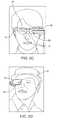
- stereoscopic wearable glasses ( 8 ) type configurationshave been developed which generally feature two displays ( 10 , 12 ) that are configured to display images with slightly different element presentation such that a three-dimensional perspective is perceived by the human visual system.
- Such configurationshave been found to be uncomfortable for many users due to a mismatch between vergence and accommodation which must be overcome to perceive the images in three dimensions; indeed, some users are not able to tolerate stereoscopic configurations.
- FIG. 2Bshows another stereoscopic wearable glasses ( 14 ) type configuration featuring two forward-oriented cameras ( 16 , 18 ) configured to capture images for an augmented reality presentation to the user through stereoscopic displays.
- the position of the cameras ( 16 , 18 ) and displaysgenerally blocks the natural field of view of the user when the glasses ( 14 ) are mounted on the user's head.
- an augmented reality configuration( 20 ) which features a visualization module ( 26 ) coupled to a glasses frame ( 24 ) which also holds conventional glasses lenses ( 22 ).
- the useris able to see an at least partially unobstructed view of the real world with such a system, and has a small display ( 28 ) with which digital imagery may be presented in an AR configuration to one eye—for a monocular AR presentation.
- FIG. 2Dfeatures a configuration wherein a visualization module ( 32 ) may be coupled to a hat or helmet ( 30 ) and configured to present monocular augmented digital imagery to a user through a small display ( 34 ).
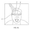
- FIG. 2Eillustrates another similar configuration wherein a frame ( 36 ) couple-able to a user's head (in a manner similar to an eyeglasses coupling) so that a visualization module ( 38 ) may be utilized to capture images and also to present monocular augmented digital imagery to a user through a small display ( 40 ).
- a visualization module38
- Such a configurationis available, for example, from Google, Inc., of Mountain View, Calif. under the trade name GoogleGlass®.
- None of these configurationsis optimally suited for presenting a rich, binocular, three-dimensional augmented reality experience in a manner that will be comfortable and maximally useful to the user, in part because prior systems fail to address some of the fundamental aspects of the human perception system, including the photoreceptors of the retina and their interoperation with the brain to produce the perception of visualization to the user.
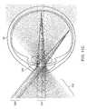
- FIG. 3a simplified cross-sectional view of a human eye is depicted featuring a cornea ( 42 ), iris ( 44 ), lens—or “crystalline lens” ( 46 ), sclera ( 48 ), choroid layer ( 50 ), macula ( 52 ), retina ( 54 ), and optic nerve pathway ( 56 ) to the brain.
- the maculais the center of the retina, which is utilized to see moderate detail; at the center of the macula is a portion of the retina that is referred to as the “fovea”, which is utilized for seeing the finest details, and which contains more photoreceptors (approximately 120 cones per visual degree) than any other portion of the retina.
- the human visual systemis not a passive sensor type of system; it is configured to actively scan the environment.
- the photoreceptors of the eyefire in response to changes in stimulation, rather than constantly responding to a constant state of stimulation.
- motionis required to present photoreceptor information to the brain (as is motion of the linear scanner array across a piece of paper in a flatbed scanner, or motion of a finger across a word of Braille imprinted into a paper).
- the fovea of the retinacontains the greatest density of photoreceptors, and while humans typically have the perception that they have high-resolution visualization capabilities throughout their field of view, they generally actually have only a small high-resolution center that is mechanically sweeping around a lot, along with a persistent memory of the high-resolution information recently captured with the fovea.
- the focal distance control mechanism of the eye(ciliary muscles operatively coupled to the crystalline lens in a manner wherein ciliary relaxation causes taut ciliary connective fibers to flatten out the lens for more distant focal lengths; ciliary contraction causes loose ciliary connective fibers, which allow the lens to assume a more rounded geometry for more close-in focal lengths) dithers back and forth by approximately 1 ⁇ 4 to 1 ⁇ 2 diopter to cyclically induce a small amount of what is called “dioptric blur” on both the close side and far side of the targeted focal length; this is utilized by the accommodation control circuits of the brain as cyclical negative feedback that helps to constantly correct course and keep the retinal image of a fixated object approximately in focus.
- the visualization center of the brainalso gains valuable perception information from the motion of both eyes and components thereof relative to each other.
- Vergence movementsi.e., rolling movements of the pupils toward or away from each other to converge the lines of sight of the eyes to fixate upon an object
- vergence movements of the two eyes relative to each otherare closely associated with focusing (or “accommodation”) of the lenses of the eyes.
- accommodation movementsi.e., rolling movements of the pupils toward or away from each other to converge the lines of sight of the eyes to fixate upon an object
- accommodationor “accommodation”
- Movement of the headwhich houses the eyes, also has a key impact upon visualization of objects.
- Humansmove their heads to visualize the world around them; they often are in a fairly constant state of repositioning and reorienting the head relative to an object of interest. Further, most people prefer to move their heads when their eye gaze needs to move more than about 20 degrees off center to focus on a particular object (i.e., people do not typically like to look at things “from the corner of the eye”). Humans also typically scan or move their heads in relation to sounds—to improve audio signal capture and utilize the geometry of the ears relative to the head.
- the human visual systemgains powerful depth cues from what is called “head motion parallax”, which is related to the relative motion of objects at different distances as a function of head motion and eye vergence distance (i.e., if a person moves his head from side to side and maintains fixation on an object, items farther out from that object will move in the same direction as the head; items in front of that object will move opposite the head motion; these are very salient cues for where things are spatially in the environment relative to the person—perhaps as powerful as stereopsis). Head motion also is utilized to look around objects, of course.
- head and eye motionare coordinated with something called the “vestibulo-ocular reflex”, which stabilizes image information relative to the retina during head rotations, thus keeping the object image information approximately centered on the retina.
- the vestibulo-ocular reflexIn response to a head rotation, the eyes are reflexively and proportionately rotated in the opposite direction to maintain stable fixation on an object.
- many humanscan read a book while shaking their head back and forth (interestingly, if the book is panned back and forth at the same speed with the head approximately stationary, the same generally is not true—the person is not likely to be able to read the moving book; the vestibulo-ocular reflex is one of head and eye motion coordination, generally not developed for hand motion).
- This paradigmmay be important for augmented reality systems, because head motions of the user may be associated relatively directly with eye motions, and the system preferably will be ready to work with this relationship.
- the 2-D oil painting objectmay be head-centric, in which case the object moves around along with the user's head (e.g., as in a GoogleGlass approach); or the object may be world-centric, in which case it may be presented as though it is part of the real world coordinate system, so that the user may move his head or eyes without moving the position of the object relative to the real world.
- the objectshould be presented as world centric (i.e., the virtual object stays in position in the real world so that the user may move his body, head, eyes around it without changing its position relative to the real world objects surrounding it, such as a real world wall); body, or torso, centric, in which case a virtual element may be fixed relative to the user's torso, so that the user can move his head or eyes without moving the object, but that is slaved to torso movements; head centric, in which case the displayed object (and/or display itself) may be moved along with head movements, as described above in reference to GoogleGlass; or eye centric, as in a “foveated display” configuration, as is described below, wherein content is slewed around as a function of the eye position.
- world centrici.e., the virtual object stays in position in the real world so that the user may move his body, head, eyes around it without changing its position relative to the real world objects surrounding it, such as a real world wall
- Embodiments of the present inventionare directed to devices, systems and methods for facilitating virtual reality and/or augmented reality interaction for one or more users.
- a system for displaying virtual contentis disclosed.
- a wearable augmented reality display systemcomprises a vision system having one or more optical elements to project one or more images to a user, and a processor communicatively coupled to a mapping database for retrieving a map data corresponding to one or more real objects of the world, the mapping database receiving inputs from at least a component of one or more wearable augmented reality display systems, wherein the processor processes the retrieved map data to determine one or more output parameters, and wherein the processor further controls the vision system in a manner such that the one or more images projected to the user are based at least in part on the determined output parameters.
- a method of displaying augmented realitycomprises retrieving a map data from a mapping database, wherein the map data corresponds to one or more real objects of the world, and wherein the mapping database receives inputs from at least a component of one or more wearable augmented reality display systems, processing the retrieved map data to determine one or more output parameters, and projecting one or more images to a user, wherein the one or more images are projected based at least in part on the determined output parameters.
- an augmented reality display systemcomprises a vision system having one or more optical elements to project one or more images to a user, a mapping database comprising map data corresponding to one or more real objects of the world, wherein the mapping database receives inputs from at least a component of one or more wearable augmented reality display systems, and a processor communicatively coupled to the mapping database for retrieving the map data and processing the retrieved map data to determine one or more output parameters, wherein the processor further controls the vision system in a manner such that the one or more images are projected to the user based at least in part on the determined output parameters.
- FIG. 1illustrates a user's view of augmented reality (AR) through a wearable AR user device, in one illustrated embodiment.
- ARaugmented reality
- FIGS. 2A-2Eillustrates various embodiments of wearable AR devices.
- FIG. 3illustrates a cross-sectional view of the human eye, in one illustrated embodiment.
- FIGS. 4A-4Dillustrate one or more embodiments of various internal processing components of the wearable AR device.
- FIGS. 5A-5Hillustrate embodiments of transmitting focused light to a user through a transmissive beamsplitter substrate.
- FIGS. 6A and 6Billustrate embodiments of coupling a lens element with the transmissive beamsplitter substrate of FIGS. 5A-5H .
- FIGS. 7A and 7Billustrate embodiments of using one or more waveguides to transmit light to a user.
- FIGS. 8A-8Qillustrate embodiments of a diffractive optical element (DOE).
- DOEdiffractive optical element
- FIGS. 9A and 9Billustrate a wavefront produced from a light projector, according to one illustrated embodiment.
- FIG. 10illustrates an embodiment of a stacked configuration of multiple transmissive beamsplitter substrate coupled with optical elements, according to one illustrated embodiment.
- FIGS. 11A-11Cillustrate a set of beamlets projected into a user's pupil, according to the illustrated embodiments.
- FIGS. 12A and 12Billustrate configurations of an array of microprojectors, according to the illustrated embodiments.
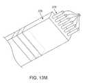
- FIGS. 13A-13Millustrate embodiments of coupling microprojectors with optical elements, according to the illustrated embodiments.
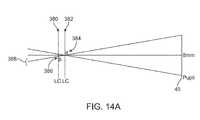
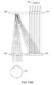
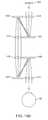
- FIGS. 14A-14Fillustrate embodiments of spatial light modulators coupled with optical elements, according to the illustrated embodiments.
- FIGS. 15A-15Cillustrate the use of a wedge type waveguides along with a plurality of light sources, according to the illustrated embodiments.
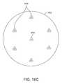
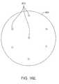
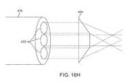
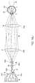
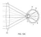
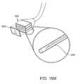
- FIGS. 16A-16Oillustrate embodiments of coupling optical elements to optical fibers, according to the illustrated embodiments.
- FIG. 17illustrates a notch filter, according to one illustrated embodiment.
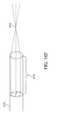
- FIG. 18illustrates a spiral pattern of a fiber scanning display, according to one illustrated embodiment.
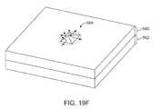
- FIGS. 19A-19Nillustrate occlusion effects in presenting a darkfield to a user, according to the illustrated embodiments.
- FIGS. 20A-20Oillustrate embodiments of various waveguide assemblies, according to the illustrated embodiments.
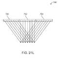
- FIGS. 21A-21Nillustrate various configurations of DOEs coupled to other optical elements, according to the illustrated embodiments.
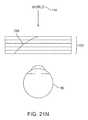
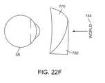
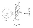
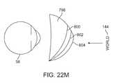
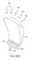
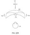
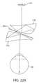
- FIGS. 22A-22Yillustrate various configurations of freeform optics, according to the illustrated embodiments.
- FIG. 23illustrates a system architecture of the AR system, according to the illustrated embodiment.
- FIGS. 4A-4Dsome general componentry options are illustrated.
- various systems, subsystems, and componentsare presented for addressing the objectives of providing a high-quality, comfortably-perceived display system for human VR and/or AR.
- an AR system user ( 60 )is depicted wearing a frame ( 64 ) structure coupled to a display system ( 62 ) positioned in front of the eyes of the user.
- a speaker ( 66 )is coupled to the frame ( 64 ) in the depicted configuration and positioned adjacent the ear canal of the user (in one embodiment, another speaker, not shown, is positioned adjacent the other ear canal of the user to provide for stereo/shapeable sound control).
- the display ( 62 )is operatively coupled ( 68 ), such as by a wired lead or wireless connectivity, to a local processing and data module ( 70 ) which may be mounted in a variety of configurations, such as fixedly attached to the frame ( 64 ), fixedly attached to a helmet or hat ( 80 ) as shown in the embodiment of FIG. 4B , embedded in headphones, removably attached to the torso ( 82 ) of the user ( 60 ) in a backpack-style configuration as shown in the embodiment of FIG. 4C , or removably attached to the hip ( 84 ) of the user ( 60 ) in a belt-coupling style configuration as shown in the embodiment of FIG. 4D .
- the local processing and data module ( 70 )may comprise a power-efficient processor or controller, as well as digital memory, such as flash memory, both of which may be utilized to assist in the processing, caching, and storage of data.
- the datamay refer to data a) captured from sensors which may be operatively coupled to the frame ( 64 ), such as image capture devices (such as cameras), microphones, inertial measurement units, accelerometers, compasses, GPS units, radio devices, and/or gyros; and/or b) acquired and/or processed using the remote processing module ( 72 ) and/or remote data repository ( 74 ), possibly for passage to the display ( 62 ) after such processing or retrieval.
- the local processing and data module ( 70 )may be operatively coupled ( 76 , 78 ), such as via a wired or wireless communication links, to the remote processing module ( 72 ) and remote data repository ( 74 ) such that these remote modules ( 72 , 74 ) are operatively coupled to each other and available as resources to the local processing and data module ( 70 ).
- the remote processing module ( 72 )may comprise one or more relatively powerful processors or controllers configured to analyze and process data and/or image information.
- the remote data repository ( 74 )may comprise a relatively large-scale digital data storage facility, which may be available through the internet or other networking configuration in a “cloud” resource configuration. In one embodiment, all data is stored and all computations are performed in the local processing and data module, allowing fully autonomous use from any remote modules.
- FIGS. 5A through 22Yvarious display configurations are presented that are designed to present the human eyes with photon-based radiation patterns that can be comfortably perceived as augmentations to physical reality, with high-levels of image quality and three-dimensional perception, as well as being capable of presenting two-dimensional content.
- a transmissive beamsplitter substrate ( 104 ) with a 45-degree reflecting surface ( 102 )directs incoming radiation ( 106 ).
- the incoming radiationmay be output from a lens (not shown), through the pupil ( 45 ) of the eye ( 58 ) and to the retina ( 54 ).
- the field of view for such a systemis limited by the geometry of the beamsplitter ( 104 ).
- a larger field of viewcan be created by aggregating the outputs/reflections of various different reflective and/or diffractive surfaces and using, e.g., a frame-sequential configuration wherein the eye ( 58 ) is presented with a sequence of frames at a high frequency that provides the perception of a single coherent scene.
- the reflectorsmay separate content by other means, such as polarization selectivity or wavelength selectivity.
- the reflectorscan relay the three-dimensional wavefronts associated with true-three-dimensional viewing of actual physical objects.
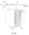
- a substrate ( 108 )comprising a plurality of reflectors at a plurality of angles ( 110 ) is shown, with each reflector actively reflecting in the depicted configuration for illustrative purposes.
- the reflectorsmay be switchable elements to facilitate temporal selectivity.
- the reflective surfaceswould intentionally be sequentially activated with frame-sequential input information ( 106 ), in which each reflective surface presents a narrow-field-of-view sub-image which is tiled with other narrow-field-of-view sub-images presented by the other reflective surfaces to form a composite wide-field-of-view image.
- frame-sequential input information106
- surface ( 110 ), about in the middle of substrate ( 108 ),is switched “on” to a reflecting state, such that it reflects incoming image information ( 106 ) to present a relatively narrow field of view sub-image in the middle of a larger field of view, while the other potential reflective surfaces are in a transmissive state.
- FIG. 5Cincoming image information ( 106 ) coming from the right of the narrow field of view sub-image (as shown by the angle of incoming beams 106 relative to the substrate 108 input interface 112 , and the resultant angle at which they exit the substrate 108 ) is reflected toward the eye ( 58 ) from reflective surface ( 110 ).
- FIG. 5Dillustrates the same reflector ( 110 ) active, with image information coming from the middle of the narrow field of view sub-image, as shown by the angle of the input information ( 106 ) at the input interface ( 112 ) and its angle as it exits substrate ( 108 ).
- FIG. 5Eillustrates the same reflector ( 110 ) active, with image information coming from the left of the field of view, as shown by the angle of the input information ( 106 ) at the input interface ( 112 ) and the resultant exit angle at the surface of the substrate ( 108 ).
- FIG. 5Fillustrates a configuration wherein the bottom reflector ( 110 ) is active, with image information ( 106 ) coming in from the far right of the overall field of view.
- FIGS. 5C, 5D, and 5Ecan illustrate one frame representing the center of a frame-sequential tiled image
- FIG. 5Fcan illustrate a second frame representing the far right of that tiled image.
- the light carrying the image information ( 106 )may strike the reflective surface ( 110 ) directly after entering substrate ( 108 ) at input interface ( 112 ), without first reflecting from the surfaces of substrate ( 108 ).
- the light carrying the image information ( 106 )may reflect from one or more surfaces of substrate ( 108 ) after entering at input interface ( 112 ) and before striking the reflective surface ( 110 ); for instance, substrate ( 108 ) may act as a planar waveguide, propagating the light carrying image information ( 106 ) by total internal reflection.
- Lightmay also reflect from one or more surfaces of the substrate ( 108 ) from a partially reflective coating, a wavelength-selective coating, an angle-selective coating, and/or a polarization-selective coating.
- the angled reflectorsmay be constructed using an electro-active material, such that upon application of a voltage and/or current to a particular reflector, the refractive index of the material comprising such reflector changes from an index substantially matched to the rest of the substrate ( 108 ), in which case the reflector is in a transmissive configuration, to a reflective configuration wherein the refractive index of the reflector mismatches the refractive index of the substrate ( 108 ) such that a reflection effect is created.
- Example electro-active materialincludes lithium niobate and electro-active polymers.
- Suitable substantially transparent electrodes for controlling a plurality of such reflectorsmay comprise materials such as indium tin oxide, which is utilized in liquid crystal displays.
- the electro-active reflectors ( 110 )may comprise liquid crystal, embedded in a substrate ( 108 ) host medium such as glass or plastic.
- liquid crystalmay be selected that changes refractive index as a function of an applied electric signal, so that more analog changes may be accomplished as opposed to binary (from one transmissive state to one reflective state).
- an input displaythat can refresh at the rate of about 360 Hz, with an electro-active reflector array that can keep up with such frequency.
- lithium niobatemay be utilized as an electro-active reflective material as opposed to liquid crystal; lithium niobate is utilized in the photonics industry for high-speed switches and fiber optic networks and has the capability to switch refractive index in response to an applied voltage at a very high frequency; this high frequency may be used to steer line-sequential or pixel-sequential sub-image information, especially if the input display is a scanned light display, such as a fiber-scanned display or scanning mirror-based display.
- a variable switchable angled mirror configurationmay comprise one or more high-speed mechanically repositionable reflective surfaces, such as a MEMS (micro-electro-mechanical system) device.
- a MEMS devicemay include what is known as a “digital mirror device”, or “DMD”, (often part of a “digital light processing”, or “DLP” system, such as those available from Texas Instruments, Inc.).
- DMDdigital mirror device
- DLPdigital light processing
- a plurality of air-gapped (or in vacuum) reflective surfacescould be mechanically moved in and out of place at high frequency.
- a single reflective surfacemay be moved up and down and re-pitched at a very high frequency.
- the switchable variable angle reflector configurations described hereinare capable of passing not only collimated or flat wavefront information to the retina ( 54 ) of the eye ( 58 ), but also curved wavefront ( 122 ) image information, as shown in the illustration of FIG. 5G .
- the ability to pass curved wavefront informationfacilitates the ability of configurations such as those shown in FIGS. 5B-5H to provide the retina ( 54 ) with input perceived as focused at various distances from the eye ( 58 ), not just optical infinity (which would be the interpretation of collimated light absent other cues).
- an array of static partially reflective surfaces ( 116 )may be embedded in a substrate ( 114 ) with a high-frequency gating layer ( 118 ) controlling outputs to the eye ( 58 ) by only allowing transmission through an aperture ( 120 ) which is controllably movable. In other words, everything may be selectively blocked except for transmissions through the aperture ( 120 ).
- the gating layer ( 118 )may comprise a liquid crystal array, a lithium niobate array, an array of MEMS shutter elements, an array of DLP DMD elements, or an array of other MEMS devices configured to pass or transmit with relatively high-frequency switching and high transmissibility upon being switched to transmission mode.
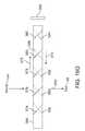
- FIGS. 6A-6Bother embodiments are depicted wherein arrayed optical elements may be combined with exit pupil expansion configurations to assist with the comfort of the virtual or augmented reality experience of the user.
- exit pupilfor the optics configuration, the user's eye positioning relative to the display (which, as in FIGS. 4A-4D , may be mounted on the user's head in an eyeglasses sort of configuration) is not as likely to disrupt his experience—because due to the larger exit pupil of the system, there is a larger acceptable area wherein the user's anatomical pupil may be located to still receive the information from the display system as desired.
- the systemis less likely to be sensitive to slight misalignments of the display relative to the user's anatomical pupil, and greater comfort for the user may be achieved through less geometric constraint on his or her relationship with the display/glasses.
- the display ( 140 ) on the leftfeeds a set of parallel rays into the substrate ( 124 ).
- the displaymay be a scanned fiber display scanning a narrow beam of light back and forth at an angle as shown to project an image through the lens or other optical element ( 142 ), which may be utilized to collect the angularly-scanned light and convert it to a parallel bundle of rays.
- the raysmay be reflected from a series of reflective surfaces ( 126 , 128 , 130 , 132 , 134 , 136 ) which may be configured to partially reflect and partially transmit incoming light so that the light may be shared across the group of reflective surfaces ( 126 , 128 , 130 , 132 , 134 , 136 ) approximately equally.
- the exiting light raysmay be steered through a nodal point and scanned out toward the eye ( 58 ) to provide an array of exit pupils, or the functional equivalent of one large exit pupil that is usable by the user as he or she gazes toward the display system.
- a similar set of lenses ( 139 )may be presented on the opposite side of the waveguide ( 124 ) to compensate for the lower set of lenses; thus creating a the equivalent of a zero-magnification telescope.
- the reflective surfaces ( 126 , 128 , 130 , 132 , 134 , 136 )each may be aligned at approximately 45 degrees as shown, or may be configured to have different alignments, akin to the configurations of FIGS. 5B-5H , for example).
- the reflective surfacesmay comprise wavelength-selective reflectors, band pass reflectors, half silvered mirrors, or other reflective configurations.
- the lenses ( 138 , 139 ) shownare refractive lenses, but diffractive lens elements may also be utilized.
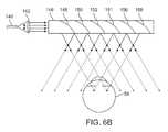
- FIG. 6Ba somewhat similar configuration is depicted wherein a plurality of curved reflective surfaces ( 148 , 150 , 152 , 154 , 156 , 158 ) may be utilized to effectively combine the lens (element 138 of FIG. 6A ) and reflector (elements 126 , 128 , 130 , 132 , 134 , 136 of FIG. 6A ) functionality of the embodiment of FIG. 6A , thereby obviating the need for the two groups of lenses (element 138 of FIG. 6A ).
- the curved reflective surfacesmay be various curved configurations selected to both reflect and impart angular change, such as parabolic or elliptical curved surfaces.
- a parabolic shapea parallel set of incoming rays will be collected into a single output point; with an elliptical configuration, a set of rays diverging from a single point of origin are collected to a single output point.
- an elliptical configurationa set of rays diverging from a single point of origin are collected to a single output point.
- the curved reflective surfaces ( 148 , 150 , 152 , 154 , 156 , 158 )preferably are configured to partially reflect and partially transmit so that the incoming light is shared across the length of the waveguide ( 146 ).
- the curved reflective surfaces ( 148 , 150 , 152 , 154 , 156 , 158 )may comprise wavelength-selective notch reflectors, half silvered mirrors, or other reflective configurations.
- the curved reflective surfaces ( 148 , 150 , 152 , 154 , 156 , 158 )may be replaced with diffractive reflectors that are configured to reflect and also deflect.
- perceptions of Z-axis differencemay be facilitated by using a waveguide in conjunction with a variable focus optical element configuration.
- image information from a display ( 160 )may be collimated and injected into a waveguide ( 164 ) and distributed in a large exit pupil manner using, e.g., configurations such as those described in reference to FIGS.
- variable focus optical element capabilitymay be utilized to change the focus of the wavefront of light emerging from the waveguide and provide the eye with the perception that the light coming from the waveguide ( 164 ) is from a particular focal distance.
- variable focus optical element capabilitysince the incoming light has been collimated to avoid challenges in total internal reflection waveguide configurations, it will exit in collimated fashion. This requires a viewer's eye to accommodate to the far point in order to bring it into focus on the retina, and naturally be interpreted as being from optical infinity—unless some other intervention causes the light to be refocused and perceived as from a different viewing distance.
- One suitable such interventionmay be a variable focus lens.
- collimated image informationis injected into a piece of glass ( 162 ) or other material at an angle such that it totally internally reflects and is passed into the adjacent waveguide ( 164 ).
- the waveguide ( 164 )may be configured akin to the waveguides of FIG. 6A or 6B ( 124 , 146 , respectively) so that the collimated light from the display is distributed to exit somewhat uniformly across the distribution of reflectors or diffractive features along the length of the waveguide.
- variable focus lens element ( 166 )Upon exit toward the eye ( 58 ), in the depicted configuration the exiting light is passed through a variable focus lens element ( 166 ) wherein, depending upon the controlled focus of the variable focus lens element ( 166 ), the light exiting the variable focus lens element ( 166 ) and entering the eye ( 58 ) will have various levels of focus (a collimated flat wavefront to represent optical infinity, more and more beam divergence/wavefront curvature to represent closer viewing distance relative to the eye 58 ).
- variable focus lens element ( 166 ) between the eye ( 58 ) and the waveguide ( 164 )another similar variable focus lens element ( 167 ) is placed on the opposite side of the waveguide ( 164 ) to cancel out the optical effects of the lenses ( 166 ) for light coming from the world ( 144 ) for augmented reality (i.e., as described above, one lens compensates for the other, producing the functional equivalent of a zero-magnification telescope).
- the variable focus lens element ( 166 )may be a refractive element, such as a liquid crystal lens, an electro-active lens, a conventional refractive lens with moving elements, a mechanical-deformation-based lens (such as a fluid-filled membrane lens, or a lens akin to the human crystalline lens wherein a flexible element is flexed and relaxed by actuators), an electrowetting lens, or a plurality of fluids with different refractive indices.
- a refractive elementsuch as a liquid crystal lens, an electro-active lens, a conventional refractive lens with moving elements, a mechanical-deformation-based lens (such as a fluid-filled membrane lens, or a lens akin to the human crystalline lens wherein a flexible element is flexed and relaxed by actuators), an electrowetting lens, or a plurality of fluids with different refractive indices.
- variable focus lens element ( 166 )may also comprise a switchable diffractive optical element (such as one featuring a polymer dispersed liquid crystal approach wherein a host medium, such as a polymeric material, has microdroplets of liquid crystal dispersed within the material; when a voltage is applied, the molecules re-orient so that their refractive indices no longer match that of the host medium, thereby creating a high-frequency switchable diffraction pattern).
- a switchable diffractive optical elementsuch as one featuring a polymer dispersed liquid crystal approach wherein a host medium, such as a polymeric material, has microdroplets of liquid crystal dispersed within the material; when a voltage is applied, the molecules re-orient so that their refractive indices no longer match that of the host medium, thereby creating a high-frequency switchable diffraction pattern).
- One embodimentincludes a host medium in which microdroplets of a Kerr effect-based electro-active material, such as lithium niobate, is dispersed within the host medium, enabling refocusing of image information on a pixel-by-pixel or line-by-line basis, when coupled with a scanning light display, such as a fiber-scanned display or scanning-mirror-based display.
- a scanning light displaysuch as a fiber-scanned display or scanning-mirror-based display.
- the pattern spacingmay be modulated to not only change the focal power of the variable focus lens element ( 166 ), but also to change the focal power of the overall optical system—for a zoom lens type of functionality.
- the lenses ( 166 )could be telecentric, in that focus of the display imagery can be altered while keeping magnification constant—in the same way that a photography zoom lens may be configured to decouple focus from zoom position.
- the lenses ( 166 )may be non-telecentric, so that focus changes will also slave zoom changes. With such a configuration, such magnification changes may be compensated for in software with dynamic scaling of the output from the graphics system in sync with focus changes).
- a stack of sequential two-dimensional imagesmay be fed to the display sequentially to produce three-dimensional perception over time; in a manner akin to the manner in which a computed tomography system uses stacked image slices to represent a three-dimensional structure.
- a series of two-dimensional image slicesmay be presented to the eye, each at a different focal distance to the eye, and the eye/brain would integrate such a stack into a perception of a coherent three-dimensional volume.
- line-by-line, or even pixel-by-pixel sequencingmay be conducted to produce the perception of three-dimensional viewing. For example, with a scanned light display (such as a scanning fiber display or scanning mirror display), the display is presenting the waveguide ( 164 ) with one line or one pixel at a time in a sequential fashion.
- variable focus lens element ( 166 )is able to keep up with the high-frequency of pixel-by-pixel or line-by-line presentation, then each line or pixel may be presented and dynamically focused through the variable focus lens element ( 166 ) to be perceived at a different focal distance from the eye ( 58 ).
- Pixel-by-pixel focus modulationgenerally requires an extremely fast/high-frequency variable focus lens element ( 166 ).
- a 1080P resolution display with an overall frame rate of 60 frames per secondtypically presents around 125 million pixels per second.
- Such a configurationalso may be constructed using a solid state switchable lens, such as one using an electro-active material, e.g., lithium niobate or an electro-active polymer.
- a frame sequential multi-focal display driving approachmay be used in conjunction with a number of the display system and optics embodiments described in this disclosure.
- an electro-active layer ( 172 )(such as one comprising liquid crystal or lithium niobate) surrounded by functional electrodes ( 170 , 174 ) which may be made of indium tin oxide
- a waveguide ( 168 ) with a conventional transmissive substrate ( 176 , such as one made from glass or plastic with known total internal reflection characteristics and an index of refraction that matches the on or off state of the electro-active layer 172 )may be controlled such that the paths of entering beams may be dynamically altered to essentially create a time-varying light field.
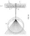
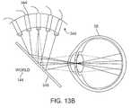
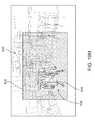
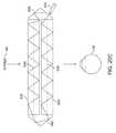
- a stacked waveguide assembly( 178 ) may be utilized to provide three-dimensional perception to the eye/brain by having a plurality of waveguides ( 182 , 184 , 186 , 188 , 190 ) and a plurality of weak lenses ( 198 , 196 , 194 , 192 ) configured together to send image information to the eye with various levels of wavefront curvature.
- Each waveguide levelmay be indicative of focal distance to be perceived for that waveguide level.
- a plurality of displays( 200 , 202 , 204 , 206 , 208 ), or in another embodiment a single multiplexed display, may be utilized to inject collimated image information into the waveguides ( 182 , 184 , 186 , 188 , 190 ), each of which may be configured, as described above, to distribute incoming light substantially equally across the length of each waveguide, for exit down toward the eye.
- the waveguide ( 182 ) nearest the eyeis configured to deliver collimated light, as injected into such waveguide ( 182 ), to the eye, which may be representative of the optical infinity focal plane.
- the next waveguide up ( 184 )is configured to send out collimated light which passes through the first weak lens ( 192 ; e.g., a weak negative lens) before it can reach the eye ( 58 ); such first weak lens ( 192 ) may be configured to create a slight convex wavefront curvature so that the eye/brain interprets light coming from that next waveguide up ( 184 ) as coming from a first focal plane closer inward toward the person from optical infinity.
- the third up waveguide ( 186 )passes its output light through both the first ( 192 ) and second ( 194 ) lenses before reaching the eye ( 58 ); the combined optical power of the first ( 192 ) and second ( 194 ) lenses may be configured to create another incremental amount of wavefront divergence so that the eye/brain interprets light coming from the third waveguide ( 186 ) as coming from a second focal plane that is even closer inward toward the person from optical infinity than was light from the next waveguide up ( 184 ).
- the other waveguide layers ( 188 , 190 ) and weak lenses ( 196 , 198 )are similarly configured, with the highest waveguide ( 190 ) in the stack sending its output through all of the weak lenses between it and the eye for an aggregate focal power representative of the closest focal plane to the person.
- a compensating lens layer ( 180 )is disposed at the top of the stack to compensate for the aggregate power of the lens stack ( 198 , 196 , 194 , 192 ) below.
- Such a configurationprovides as many perceived focal planes as there are available waveguide/lens pairings, again with a relatively large exit pupil configuration as described above.
- Both the reflective aspects of the waveguides and the focusing aspects of the lensesmay be static (i.e., not dynamic or electro-active). In an alternative embodiment they may be dynamic using electro-active features as described above, enabling a small number of waveguides to be multiplexed in a time sequential fashion to produce a larger number of effective focal planes.
- FIGS. 8B-8Nvarious aspects of diffraction configurations for focusing and/or redirecting collimated beams are depicted. Other aspects of diffraction systems for such purposes are disclosed in U.S. Patent Application Ser. No. 61/845,907 (U.S. patent application Ser. No. 14/331,218), which is incorporated by reference herein in its entirety.
- a linear diffraction patternsuch as a Bragg grating
- FIG. 8Cillustrates the deflection effect of passing a collimated beam through a linear diffraction pattern ( 210 );
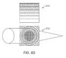
- FIG. 8Dillustrates the focusing effect of passing a collimated beam through a radially symmetric diffraction pattern ( 212 ).
- a combination diffraction pattern that has both linear and radial elements ( 214 )produces both deflection and focusing of a collimated input beam.
- These deflection and focusing effectscan be produced in a reflective as well as transmissive mode.
- These principlesmay be applied with waveguide configurations to allow for additional optical system control, as shown in FIGS. 8G-8N , for example. As shown in FIGS.
- a diffraction pattern ( 220 ), or “diffractive optical element” (or “DOE”)has been embedded within a planar waveguide ( 216 ) such that as a collimated beam is totally internally reflected along the planar waveguide ( 216 ), it intersects the diffraction pattern ( 220 ) at a multiplicity of locations.
- DOEdiffractive optical element
- the DOE ( 220 )has a relatively low diffraction efficiency so that only a portion of the light of the beam is deflected away toward the eye ( 58 ) with each intersection of the DOE ( 220 ) while the rest continues to move through the planar waveguide ( 216 ) via total internal reflection.
- the light carrying the image informationis thus divided into a number of related light beams that exit the waveguide at a multiplicity of locations and the result is a fairly uniform pattern of exit emission toward the eye ( 58 ) for this particular collimated beam bouncing around within the planar waveguide ( 216 ), as shown in FIG. 8H .
- the exit beams toward the eye ( 58 )are shown in FIG.
- the exit beam patternis more divergent, which would require the eye to accommodation to a closer distance to bring it into focus on the retina and would be interpreted by the brain as light from a viewing distance closer to the eye than optical infinity.
- a DOE ( 221 ) embedded in this other waveguide ( 218 ), such as a linear diffraction pattern,may function to spread the light across the entire larger planar waveguide ( 216 ), which functions to provide the eye ( 58 ) with a very large incoming field of incoming light that exits from the larger planar waveguide ( 216 ), i.e., a large eye box, in accordance with the particular DOE configurations at work.
- the DOEs ( 220 , 221 )are depicted bisecting the associated waveguides ( 216 , 218 ) but this need not be the case; they could be placed closer to, or upon, either side of either of the waveguides ( 216 , 218 ) to have the same functionality.
- FIG. 8Kwith the injection of a single collimated beam, an entire field of cloned collimated beams may be directed toward the eye ( 58 ).
- a combined linear diffraction pattern/radially symmetric diffraction pattern scenariosuch as that depicted in FIGS.
- a beam distribution waveguide opticfor functionality such as exit pupil functional expansion; with a configuration such as that of FIG. 8K , the exit pupil can be as large as the optical element itself, which can be a very significant advantage for user comfort and ergonomics
- Z-axis focusing capabilityis presented, in which both the divergence angle of the cloned beams and the wavefront curvature of each beam represent light coming from a point closer than optical infinity.
- one or more DOEsare switchable between “on” states in which they actively diffract, and “off” states in which they do not significantly diffract.
- a switchable DOEmay comprise a layer of polymer dispersed liquid crystal, in which microdroplets comprise a diffraction pattern in a host medium, and the refractive index of the microdroplets can be switched to substantially match the refractive index of the host material (in which case the pattern does not appreciably diffract incident light) or the microdroplet can be switched to an index that does not match that of the host medium (in which case the pattern actively diffracts incident light).
- the diffraction termssuch as the linear diffraction pitch term as in FIGS.
- a beam scanning or tiling functionalitymay be achieved.
- Configurations such as those illustrated in FIG. 8Kpreferably are driven with injection of image information in a time sequential approach, with frame sequential driving being the most straightforward to implement.
- an image of the sky at optical infinitymay be injected at time1 and the diffraction grating retaining collimation of light may be utilized; then an image of a closer tree branch may be injected at time2 while a DOE controllably imparts a focal change, say one diopter or 1 meter away, to provide the eye/brain with the perception that the branch light information is coming from the closer focal range.
- This kind of paradigmcan be repeated in rapid time-sequential fashion such that the eye/brain perceives the input to be all part of the same image.
- This kind of configurationgenerally assumes that the DOE is switched at a relatively low speed (i.e., in sync with the frame-rate of the display that is injecting the images—in the range of tens to hundreds of cycles/second).
- the opposite extrememay be a configuration wherein DOE elements can shift focus at tens to hundreds of MHz or greater, which facilitates switching of the focus state of the DOE elements on a pixel-by-pixel basis as the pixels are scanned into the eye ( 58 ) using a scanned light display type of approach.
- Thisis desirable because it means that the overall display frame-rate can be kept quite low; just low enough to make sure that “flicker” is not a problem (in the range of about 60-120 frames/sec).
- the DOEscan be switched at KHz rates, then on a line-by-line basis the focus on each scan line may be adjusted, which may afford the user with a visible benefit in terms of temporal artifacts during an eye motion relative to the display, for example.
- the different focal planes in a scenemay, in this manner, be interleaved, to minimize visible artifacts in response to a head motion (as is discussed in greater detail later in this disclosure).
- a line-by-line focus modulatormay be operatively coupled to a line scan display, such as a grating light valve display, in which a linear array of pixels is swept to form an image; and may be operatively coupled to scanned light displays, such as fiber-scanned displays and mirror-scanned light displays.
- a line scan displaysuch as a grating light valve display, in which a linear array of pixels is swept to form an image
- scanned light displayssuch as fiber-scanned displays and mirror-scanned light displays.
- a stacked configurationmay use dynamic DOEs (rather than the static waveguides and lenses of the embodiment of FIG. 8A ) to provide multi-planar focusing simultaneously.
- a primary focus plane(based upon measured eye accommodation, for example) could be presented to the user, and a + margin and ⁇ margin (i.e., one focal plane closer, one farther out) could be utilized to provide a large focal range in which the user can accommodate before the planes need be updated.
- This increased focal rangecan provide a temporal advantage if the user switches to a closer or farther focus (i.e., as determined by accommodation measurement).
- the new plane of focuscould be made to be the middle depth of focus, with the + and ⁇ margins ready for a fast switchover to either one while the system catches up.
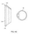
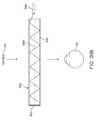
- a stack ( 222 ) of planar waveguides( 244 , 246 , 248 , 250 , 252 ) is shown, each having a reflector ( 254 , 256 , 258 , 260 , 262 ) at the end and being configured such that collimated image information injected in one end by a display ( 224 , 226 , 228 , 230 , 232 ) bounces by total internal reflection down to the reflector, at which point some or all of the light is reflected out toward an eye or other target.
- Each of the reflectorsmay have slightly different angles so that they all reflect exiting light toward a common destination such as a pupil. Such a configuration is somewhat similar to that of FIG.
- each different angled reflector in the embodiment of FIG. 8Ohas its own waveguide for less interference when projected light is travelling to the targeted reflector.
- Lenses( 234 , 236 , 238 , 240 , 242 ) may be interposed between the displays and waveguides for beam steering and/or focusing.
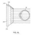
- FIG. 8Pillustrates a geometrically staggered version wherein reflectors ( 276 , 278 , 280 , 282 , 284 ) are positioned at staggered lengths in the waveguides ( 266 , 268 , 270 , 272 , 274 ) so that exiting beams may be relatively easily aligned with objects such as an anatomical pupil.
- the geometries of the reflectors ( 276 , 278 , 280 , 282 , 284 ) and waveguides ( 266 , 268 , 270 , 272 , 274 )may be set up to fill the eye pupil (typically about 8 mm across or less) with exiting light.
- the viewermay make eye movements while retaining the ability to see the displayed imagery. Referring back to the discussion related to FIGS. 5A and 5B about field of view expansion and reflector size, an expanded field of view is presented by the configuration of FIG. 8P as well, and it does not involve the complexity of the switchable reflective elements of the embodiment of FIG. 5B .
- FIG. 8Qillustrates a version wherein many reflectors ( 298 ) form a relatively continuous curved reflection surface in the aggregate or discrete flat facets that are oriented to align with an overall curve.
- the curvecould a parabolic or elliptical curve and is shown cutting across a plurality of waveguides ( 288 , 290 , 292 , 294 , 296 ) to minimize any crosstalk issues, although it also could be utilized with a monolithic waveguide configuration.
- a high-frame-rate and lower persistence displaymay be combined with a lower-frame-rate and higher persistence display and a variable focus element to comprise a relatively high-frequency frame sequential volumetric display.
- the high-frame-rate displayhas a lower bit depth
- the lower-frame-rate displayhas a higher bit-depth.
- two display elementsmay be integrated: a full-color, high-resolution liquid crystal display (“LCD”; a backlighted ferroelectric panel display also may be utilized in another embodiment; in a further embodiment a scanning fiber display may be utilized) operating at 60 frames per second, and aspects of a higher-frequency DLP system.
- LCDliquid crystal display
- a backlighted ferroelectric panel displayalso may be utilized in another embodiment; in a further embodiment a scanning fiber display may be utilized
- the conventional lighting configurationmay be removed to accommodate using the DLP projector to project a mask pattern on the back of the LCD (in one embodiment, the mask pattern may be binary in that the DLP either projects illumination, or not-illumination; in another embodiment described below, the DLP may be utilized to project a grayscale mask image).
- DLP projection systemscan operate at very high frame rates; in one embodiment for 6 depth planes at 60 frames per second, a DLP projection system can be operated against the back of the LCD display at 360 frames/second. Then the DLP projector is utilized to selectively illuminate portions of the LCD panel in sync with a high-frequency variable focus element (such as a deformable membrane mirror) that is disposed between the viewing side of the LCD panel and the eye of the user, the variable focus element being used to change the global display focus on a frame by frame basis at 360 frames/second.
- a high-frequency variable focus elementsuch as a deformable membrane mirror
- variable focus elementis positioned to be optically conjugate to the exit pupil, to enable adjustments of focus without simultaneously affecting image magnification or “zoom.”
- variable focus elementis not conjugate to the exit pupil, such that image magnification changes accompany focus adjustments, and software is used to compensate for these optical magnification changes and any distortions by pre-scaling or warping the images to be presented.
- the systemmay be configured to present on an LCD a full-color, all in-focus image of the tree branch in front the sky.
- the DLP projectorin a binary masking configuration (i.e., illumination or absence of illumination) may be used to only illuminate the portion of the LCD that represents the cloudy sky while functionally black-masking (i.e., failing to illuminate) the portion of the LCD that represents the tree branch and other elements that are not to be perceived at the same focal distance as the sky, and the variable focus element (such as a deformable membrane mirror) may be utilized to position the focal plane at optical infinity so that the eye sees a sub-image at subframe1 as being clouds that are infinitely far away.
- a binary masking configurationi.e., illumination or absence of illumination
- functionally black-maskingi.e., failing to illuminate
- the variable focus elementsuch as a deformable membrane mirror
- variable focus elementmay be switched to focusing on a point about 1 meter away from the user's eyes (or whatever distance is required; here 1 meter for the branch location is used for illustrative purposes), the pattern of illumination from the DLP can be switched so that the system only illuminates the portion of the LCD that represents the tree branch while functionally black-masking (i.e., failing to illuminate) the portion of the LCD that represents the sky and other elements that are not to be perceived at the same focal distance as the tree branch.
- the eyegets a quick flash of cloud at optical infinity followed by a quick flash of tree at 1 meter, and the sequence is integrated by the eye/brain to form a three-dimensional perception.
- the branchmay be positioned diagonally relative to the viewer, such that it extends through a range of viewing distances, e.g., it may join with the trunk at around 2 meters viewing distance while the tips of the branch are at the closer position of 1 meter.
- the display systemcan divide the 3-D volume of the tree branch into multiple slices, rather than a single slice at 1 meter.
- one focus slicemay be used to represent the sky (using the DLP to mask all areas of the tree during presentation of this slice), while the tree branch is divided across 5 focus slices (using the DLP to mask the sky and all portions of the tree except one, for each part of the tree branch to be presented).
- the depth slicesare positioned with a spacing equal to or smaller than the depth of focus of the eye, such that the viewer will be unlikely to notice the transition between slices, and instead perceive a smooth and continuous flow of the branch through the focus range.
- the DLPin a binary (illumination or darkfield only) mode, it may be utilized to project a grayscale (for example, 256 shades of grayscale) mask onto the back of the LCD panel to enhance three-dimensional perception.
- the grayscale shadesmay be utilized to impart to the eye/brain a perception that something resides in between adjacent depth or focal planes.
- the leading edge of the branch closest to the useris to be in focalplane1, then at subframe1, that portion branch on the LCD may be lit up with full intensity white from the DLP system with the variable focus element at focalplane1.
- grayscale maskingcan be utilized.
- the DLPcan project an illumination mask to that portion during both subframe1 and subframe2, but at half-illumination (such as at level 128 out of 256 grayscale) for each subframe. This provides the perception of a blending of depth of focus layers, with the perceived focal distance being proportional to the illuminance ratio between subframe1 and subframe2.
- an about 25% intensity grayscale maskcan be used to illuminate that portion of the LCD at subframe1 and an about 75% grayscale mask can be used to illuminate the same portion of the LCD at subframe2.
- bit depths of both the low-frame-rate display and the high-frame-rate displaycan be combined for image modulation, to create a high dynamic range display.
- the high dynamic range drivingmay be conducted in tandem with the focus plane addressing function described above, to comprise a high dynamic range multi-focal 3-D display.
- only a certain portion of the display (i.e., LCD) outputmay be mask-illuminated by the DMD and variably focused en route to the user's eye.
- the middle portion of the displaymay be mask illuminated, with the periphery of the display not providing varying accommodation cues to the user (i.e. the periphery could be uniformly illuminated by the DLP DMD, while a central portion is actively masked and variably focused en route to the eye).
- a refresh rate of about 360 Hzallows for 6 depth planes at about 60 frames/second each.
- even higher refresh ratesmay be achieved by increasing the operating frequency of the DLP.
- a standard DLP configurationuses a MEMS device and an array of micro-mirrors that toggle between a mode of reflecting light toward the display or user to a mode of reflecting light away from the display or user, such as into a light trap—thus they are inherently binary.
- DLPstypically create grayscale images using a pulse width modulation schema wherein the mirror is left in the “on” state for a variable amount of time for a variable duty cycle in order to create a brighter pixel, or pixel of interim brightness.
- the DLPsmay run at a much higher binary rate.
- the frame ratemay be increased significantly—by thousands of frames per second, which allows for hundreds to thousands of depth planes being refreshed at 60 frames/second, which may be utilized to obviate the between-depth-plane grayscale interpolating as described above.
- a typical pulse width modulation scheme for a Texas Instruments DLP systemhas an 8-bit command signal (first bit is the first long pulse of the mirror; second bit is a pulse that is half as long as the first; third bit is half as long again; and so on)—so that the configuration can create 2 to the 8th power different illumination levels.
- the backlighting from the DLPmay have its intensity varied in sync with the different pulses of the DMD to equalize the brightness of the sub images that are created, which is a practical workaround to get existing DMD drive electronics to produce significantly higher frame rates.
- direct control changes to the DMD drive electronics and softwaremay be utilized to have the mirrors always have an equal on-time instead of the variable on-time configuration that is conventional, which would facilitate higher frame rates.
- the DMD drive electronicsmay be configured to present low bit depth images at a frame rate above that of high bit depth images but lower than the binary frame rate, enabling some grayscale blending between focus planes, while moderately increasing the number of focus planes.
- the virtual monsterwhen limited to a finite number of depth planes, such as 6 in the example above, it is desirable to functionally move these 6 depth planes around to be maximally useful in the scene that is being presented to the user. For example, if a user is standing in a room and a virtual monster is to be placed into his augmented reality view, the virtual monster being about 2 feet deep in the Z axis straight away from the user's eyes, then it makes sense to cluster all 6 depth planes around the center of the monster's current location (and dynamically move them with him as he moves relative to the user)—so that more rich accommodation cues may be provided for the user, with all six depth planes in the direct region of the monster (for example, 3 in front of the center of the monster, 3 in back of the center of the monster). Such allocation of depth planes is content dependent.
- the same monsteris to be presented in the same room, but also to be presented to the user is a virtual window frame element, and then a virtual view to optical infinity out of the virtual window frame, it will be useful to spend at least one depth plane on optical infinity, one on the depth of the wall that is to house the virtual window frame, and then perhaps the remaining four depth planes on the monster in the room. If the content causes the virtual window to disappear, then the two depth planes may be dynamically reallocated to the region around the monster, and so on—content-based dynamic allocation of focal plane resources to provide the most rich experience to the user given the computing and presentation resources.
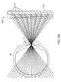
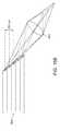
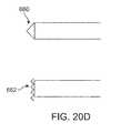
- phase delays in a multicore fiber or an array of single-core fibersmay be utilized to create variable focus light wavefronts.
- a multicore fiber ( 300 )may comprise the aggregation of multiple individual fibers ( 302 );
- FIG. 9Bshows a close-up view of a multicore assembly, which emits light from each core in the form of a spherical wavefront ( 304 ) from each.
- these small spherical wavefrontsultimately constructively and destructively interfere with each other, and if they were emitted from the multicore fiber in phase, they will develop an approximately planar wavefront ( 306 ) in the aggregate, as shown.
- phase delaysare induced between the cores (using a conventional phase modulator such as one using lithium niobate, for example, to slow the path of some cores relative to others)
- a curved or spherical wavefrontmay be created in the aggregate, to represent at the eyes/brain an object coming from a point closer than optical infinity, which presents another option that may be used in place of the variable focus elements described above.
- phased multicore configuration, or phased arraymay be utilized to create multiple optical focus levels from a light source.
- a known Fourier transform aspect of multi-mode optical fiber or light guiding rods or pipesmay be utilized for control of the wavefronts that are output from such fiber.
- Optical fiberstypically are available in two categories: single mode and multi-mode.
- Multi-mode optical fibertypically has larger core diameters and allows light to propagate along multiple angular paths, rather than just the one of single mode optical fiber. It is known that if an image is injected into one end of a multi-mode fiber, that angular differences that are encoded into that image will be retained to some degree as it propagates through the multi-mode fiber, and for some configurations the output from the fiber will be significantly similar to a Fourier transform of the image that was input.
- the inverse Fourier transform of a wavefrontmay be input so that, after passing through the fiber that optically imparts a Fourier transform, the output is the desired shaped, or focused, wavefront.
- a wavefrontsuch as a diverging spherical wavefront to represent a focal plane nearer to the user than optical infinity
- the outputis the desired shaped, or focused, wavefront.
- Such output endmay be scanned about to be used as a scanned fiber display, or may be used as a light source for a scanning mirror to form an image, for instance.
- Such a configurationmay be utilized as yet another focus modulation subsystem.
- Other kinds of light patterns and wavefrontsmay be injected into a multi-mode fiber, such that on the output end, a certain spatial pattern is emitted.
- the Fourier transform of a hologrammay be injected into the input end of a multi-mode fiber to output a wavefront that may be used for three-dimensional focus modulation and/or resolution enhancement.
- Certain single fiber core, multi-core fibers, or concentric core+cladding configurationsalso may be utilized in the aforementioned inverse Fourier transform configurations.
- a systemmay be configured to monitor the user's accommodation and rather than presenting a set of multiple different light wavefronts, present a single wavefront at a time that corresponds to the accommodation state of the eye.
- Accommodationmay be measured directly (such as by infrared autorefractor or eccentric photorefraction) or indirectly (such as by measuring the convergence level of the two eyes of the user; as described above, vergence and accommodation are strongly linked neurologically, so an estimate of accommodation can be made based upon vergence geometry).
- the wavefront presentations at the eyemay be configured for a 1 meter focal distance using any of the above variable focus configurations. If an accommodation change to focus at 2 meters is detected, the wavefront presentation at the eye may be reconfigured for a 2 meter focal distance, and so on.
- variable focus elementmay be placed in the optical path between an outputting combiner (e.g., a waveguide or beamsplitter) and the eye of the user, so that the focus may be changed along with (i.e., preferably at the same rate as) accommodation changes of the eye.
- Software effectsmay be utilized to produce variable amounts blur (e.g., Gaussian) to objects which should not be in focus to simulate the dioptric blur expected at the retina if an object were at that viewing distance and enhance the three-dimensional perception by the eyes/brain.
- a simple embodimentis a single plane whose focus level is slaved to the viewer's accommodation level, however the performance demands on the accommodation tracking system can be relaxed if even a low number of multiple planes are used.
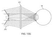
- a stack ( 328 ) of about 3 waveguides ( 318 , 320 , 322 )may be utilized to create three focal planes worth of wavefronts simultaneously.
- the weak lenses ( 324 , 326 )may have static focal distances, and a variable focal lens ( 316 ) may be slaved to the accommodation tracking of the eyes such that one of the three waveguides (say the middle waveguide 320 ) outputs what is deemed to be the in-focus wavefront, while the other two waveguides ( 322 , 318 ) output a + margin wavefront and a ⁇ margin wavefront (i.e., a little farther than detected focal distance, a little closer than detected focal distance) which may improve the three-dimensional perception and also provide enough difference for the brain/eye accommodation control system to sense some blur as negative feedback. This may enhance the perception of reality, and allows a range of accommodation before a physical adjustment of the focus levels is necessary.
- variable focus compensating lens ( 314 )is also shown to ensure that light coming in from the real world ( 144 ) in an augmented reality configuration is not refocused or magnified by the assembly of the stack ( 328 ) and output lens ( 316 ).
- the variable focus in the lenses ( 316 , 314 )may be achieved, as discussed above, with refractive, diffractive, or reflective techniques.
- each of the waveguides in a stackmay contain its own capability for changing focus (such as by having an included electronically switchable DOE) so that the variable focus element need not be centralized as in the stack ( 328 ) of the configuration of FIG. 10 .
- variable focus elementsmay be interleaved between the waveguides of a stack (i.e., rather than fixed focus weak lenses as in the embodiment of FIG. 10 ) to obviate the need for a combination of fixed focus weak lenses plus whole-stack-refocusing variable focus element.
- Such stacking configurationsmay be used in accommodation tracked variations as described herein, and also in a frame-sequential multi-focal display approach.
- a configuration wherein light enters the pupil with a small exit pupil, such as 1 ⁇ 2 mm diameter or lessone has the equivalent of a pinhole lens configuration wherein the beam is always interpreted as in-focus by the eyes/brain—e.g., a scanned light display using a 0.5 mm diameter beam to scan images to the eye.
- accommodation tracking inputmay be utilized to induce blur using software to image information that is to be perceived as at a focal plane behind or in front of the focal plane determined from the accommodation tracking.
- simulated dioptric blurmay be induced with software, and may be slaved to the accommodation tracking status.
- a scanning fiber displayis well suited to such configuration because it may be configured to only output small-diameter beams in a Maxwellian form.
- an array of small exit pupilsmay be created to increase the functional eye box of the system (and also to reduce the impact of a light-blocking particle which may reside in the vitreous or cornea of the eye), such as by one or more scanning fiber displays, or by a DOE configuration such as that described in reference to FIG. 8K , with a pitch in the array of presented exit pupils that ensure that only one will hit the anatomical pupil of the user at any given time (for example, if the average anatomical pupil diameter is 4 mm, one configuration may comprise 1 ⁇ 2 mm exit pupils spaced at intervals of approximate 4 mm apart).
- Such exit pupilsmay also be switchable in response to eye position, such that only the eye always receives one, and only one, active small exit pupil at a time; allowing a denser array of exit pupils.
- Such userwill have a large depth of focus to which software-based blur techniques may be added to enhance perceived depth perception.
- an object at optical infinitycreates a substantially planar wavefront; an object closer, such as 1 m away from the eye, creates a curved wavefront (with about 1 m convex radius of curvature).
- the eye's optical systemneeds to have enough optical power to bend the incoming rays of light such that they are focused on the retina (convex wavefront gets turned into concave, and then down to a focal point on the retina).
- light directed to the eyehas been treated as being part of one continuous wavefront, some subset of which would hit the pupil of the particular eye.
- light directed to the eyemay be effectively discretized or broken down into a plurality of beamlets or individual rays, each of which has a diameter less than about 0.5 mm and a unique propagation pathway as part of a greater aggregated wavefront that may be functionally created with the an aggregation of the beamlets or rays.
- a curved wavefrontmay be approximated by aggregating a plurality of discrete neighboring collimated beams, each of which is approaching the eye from an appropriate angle to represent a point of origin that matches the center of the radius of curvature of the desired aggregate wavefront.
- each individual beamletis always in relative focus on the retina, independent of the accommodation state of the eye—however the trajectory of each beamlet will be affected by the accommodation state. For instance, if the beamlets approach the eye in parallel, representing a discretized collimated aggregate wavefront, then an eye that is correctly accommodated to infinity will deflect the beamlets to all converge upon the same shared spot on the retina, and will appear in focus. If the eye accommodates to, say, 1 m, the beams will be converted to a spot in front of the retina, cross paths, and fall on multiple neighboring or partially overlapping spots on the retina—appearing blurred.
- the beamletsapproach the eye in a diverging configuration, with a shared point of origin 1 meter from the viewer, then an accommodation of 1 m will steer the beams to a single spot on the retina, and will appear in focus; if the viewer accommodates to infinity, the beamlets will converge to a spot behind the retina, and produce multiple neighboring or partially overlapping spots on the retina, producing a blurred image.
- the accommodation of the eyedetermines the degree of overlap of the spots on the retina, and a given pixel is “in focus” when all of the spots are directed to the same spot on the retina and “defocused” when the spots are offset from one another.
- a set of multiple narrow beamsmay be used to emulate what is going on with a larger diameter variable focus beam, and if the beamlet diameters are kept to a maximum of about 0.5 mm, then they maintain a relatively static focus level, and to produce the perception of out-of-focus when desired, the beamlet angular trajectories may be selected to create an effect much like a larger out-of-focus beam (such a defocusing treatment may not be the same as a Gaussian blur treatment as for the larger beam, but will create a multimodal point spread function that may be interpreted in a similar fashion to a Gaussian blur).
- the beamletsare not mechanically deflected to form this aggregate focus effect, but rather the eye receives a superset of many beamlets that includes both a multiplicity of incident angles and a multiplicity of locations at which the beamlets intersect the pupil; to represent a given pixel from a particular viewing distance, a subset of beamlets from the superset that comprise the appropriate angles of incidence and points of intersection with the pupil (as if they were being emitted from the same shared point of origin in space) are turned on with matching color and intensity, to represent that aggregate wavefront, while beamlets in the superset that are inconsistent with the shared point of origin are not turned on with that color and intensity (but some of them may be turned on with some other color and intensity level to represent, e.g., a different pixel).
- each of a multiplicity of incoming beamlets ( 332 )is passing through a small exit pupil ( 330 ) relative to the eye ( 58 ) in a discretized wavefront display configuration.
- a subset ( 334 ) of the group of beamlets ( 332 )may be driven with matching color and intensity levels to be perceived as though they are part of the same larger-sized ray (the bolded subgroup 334 may be deemed an “aggregated beam”).
- the subset of beamletsare parallel to one another, representing a collimated aggregate beam from optical infinity (such as light coming from a distant mountain).
- the eyeis accommodated to infinity, so the subset of beamlets are deflected by the eye's cornea and lens to all fall substantially upon the same location of the retina and are perceived to comprise a single in focus pixel.
- FIG. 11Cshows another subset of beamlets representing an aggregated collimated beam ( 336 ) coming in from the right side of the field of view of the user's eye ( 58 ) if the eye ( 58 ) is viewed in a coronal-style planar view from above. Again, the eye is shown accommodated to infinity, so the beamlets fall on the same spot of the retina, and the pixel is perceived to be in focus. If, in contrast, a different subset of beamlets were chosen that were reaching the eye as a diverging fan of rays, those beamlets would not fall on the same location of the retina (and be perceived as in focus) until the eye were to shift accommodation to a near point that matches the geometrical point of origin of that fan of rays.
- patterns of points of intersection of beamlets with the anatomical pupil of the eyei.e., the pattern of exit pupils
- theymay be organized in configurations such as a cross-sectionally efficient hex-lattice (for example, as shown in FIG. 12A ) or a square lattice or other two-dimensional array.
- a three-dimensional array of exit pupilscould be created, as well as time-varying arrays of exit pupils.
- Discretized aggregate wavefrontsmay be created using several configurations, such as an array of microdisplays or microprojectors placed optically conjugate with the exit pupil of viewing optics, microdisplay or microprojector arrays coupled to a direct field of view substrate (such as an eyeglasses lens) such that they project light to the eye directly, without additional intermediate viewing optics, successive spatial light modulation array techniques, or waveguide techniques such as those described in relation to FIG. 8K .
- a direct field of view substratesuch as an eyeglasses lens
- a lightfieldmay be created by bundling a group of small projectors or display units (such as scanned fiber displays).
- FIG. 12Adepicts a hexagonal lattice projection bundle ( 338 ) which may, for example, create a 7 mm-diameter hex array with each fiber display outputting a sub-image ( 340 ). If such an array has an optical system, such as a lens, placed in front of it such that the array is placed optically conjugate with the eye's entrance pupil, this will create an image of the array at the eye's pupil, as shown in FIG. 12B , which essentially provides the same optical arrangement as the embodiment of FIG. 11A .
- Each of the small exit pupils of the configurationis created by a dedicated small display in the bundle ( 338 ), such as a scanning fiber display. Optically, it's as though the entire hex array ( 338 ) is positioned right into the anatomical pupil ( 45 ).
- Such embodimentsare means for driving different sub images to different small exit pupils within the larger anatomical entrance pupil ( 45 ) of the eye, comprising a superset of beamlets with a multiplicity of incident angles and points of intersection with the eye pupil.
- Each of the separate projectors or displaysmay be driven with a slightly different image, such that sub images may be created that pull out different sets of rays to be driven at different light intensities and colors.
- a strict image conjugatemay be created, as in the embodiment of FIG. 12B , wherein there is direct 1 - to -1 mapping of the array ( 338 ) with the pupil ( 45 ).
- the spacingmay be changed between displays in the array and the optical system (lens 342 , in FIG. 12B ) so that instead of getting a conjugate mapping of the array to the eye pupil, the eye pupil may be catching the rays from the array at some other distance.
- FIG. 13Aanother lightfield creating embodiment is depicted wherein an array of microdisplays or microprojectors ( 346 ) may be coupled to a frame ( 344 ; such as an eyeglasses frame) to be positioned in front of the eye ( 58 ).
- the depicted configurationis a nonconjugate arrangement wherein there are no large-scale optical elements interposed between the displays (for example, scanning fiber displays) of the array ( 346 ) and the eye ( 58 ).
- the displaysfor example, scanning fiber displays
- Each displaymay be configured to create a set of rays representing different elements of the beamlet superset.
- FIG. 13Billustrates a nonconjugate configuration similar to that of FIG. 13A , with the exception that the embodiment of FIG. 13B features a reflecting surface ( 348 ) to facilitate moving the display array ( 346 ) away from the eye's ( 58 ) field of view, while also allowing views of the real world ( 144 ) through the reflective surface ( 348 ).
- Scanning fiber displayswhich may be utilized as displays may have baseline diameters in the range of 1 mm, but reduction in enclosure and projection lens hardware may decrease the diameters of such displays to about 0.5 mm or less, which is less disturbing for a user.
- Another downsizing geometric refinementmay be achieved by directly coupling a collimating lens (which may, for example, comprise a gradient refractive index, or “GRIN”, lens, a conventional curved lens, or a diffractive lens) to the tip of the scanning fiber itself in a case of a fiber scanning display array.
- GRINgradient refractive index
- a GRIN lens ( 354 )is shown fused to the end of a single mode optical fiber.
- An actuator ( 350 ; such as a piezoelectric actuator)is coupled to the fiber ( 352 ) and may be used to scan the fiber tip.
- the end of the fibermay be shaped into a hemispherical shape using a curved polishing treatment of an optical fiber to create a lensing effect.
- a standard refractive lensmay be coupled to the end of each optical fiber using an adhesive.
- a lensmay be built from a dab of transmissive polymeric material or glass, such as epoxy.
- the end of an optical fibermay be melted to create a curved surface for a lensing effect.
- FIG. 13C-2shows an embodiment wherein display configurations (i.e., scanning fiber displays with GRIN lenses; shown in close-up view of FIG. 13C-1 ) such as that shown in FIG. 13D may be coupled together through a single transparent substrate ( 356 ) preferably having a refractive index that closely matches the cladding of the optical fibers ( 352 ) so that the fibers themselves are not very visible for viewing of the outside world across the depicted assembly (if the index matching of the cladding is done precisely, then the larger cladding/housing becomes transparent and only the tiny cores, which preferably are about 3 microns in diameter, will be obstructing the view.
- the matrix ( 358 ) of displaysmay all be angled inward so they are directed toward the anatomic pupil of the user (in another embodiment, they may stay parallel to each other, but such a configuration is less efficient).
- a thin series of planar waveguides ( 358 )are configured to be cantilevered relative to a larger substrate structure ( 356 ).
- the substrate ( 356 )may be moved to produce cyclic motion (i.e., at the resonant frequency of the cantilevered members 358 ) of the planar waveguides relative to the substrate structure.
- the cantilevered waveguide portions ( 358 )may be actuated with piezoelectric or other actuators relative to the substrate.
- Image illumination informationmay be injected, for example, from the right side ( 360 ) of the substrate structure to be coupled into the cantilevered waveguide portions ( 358 ).
- the substrate ( 356 )may comprise a waveguide configured (such as with an integrated DOE configuration as described above) to totally internally reflect incoming light ( 360 ) along its length and then redirect it to the cantilevered waveguide portions ( 358 ).
- the planar waveguidesare configured to minimize any dispersion and/or focus changes with their planar shape factors.
- one way to gain further angular and spatial diversityis to use a multicore fiber and place a lens at the exit point, such as a GRIN lens, so that the exit beams are deflected through a single nodal point ( 366 ); that nodal point may then be scanned back and forth in a scanned fiber type of arrangement (such as by a piezoelectric actuator 368 ). If a retinal conjugate is placed at the plane defined at the end of the GRIN lens, a display may be created that is functionally equivalent to the general case discretized aggregate wavefront configuration described above.
- a similar effectmay be achieved not by using a lens, but by scanning the face of a multicore system at the correct conjugate of an optical system ( 372 ), the goal being to create a higher angular and spatial diversity of beams.
- some of this requisite angular and spatial diversitymay be created through the use of multiple cores to create a plane which may be relayed by a waveguide.
- a multicore fiber ( 362 )may be scanned (such as by a piezoelectric actuator 368 ) to create a set of beamlets with a multiplicity of angles of incidence and points of intersection which may be relayed to the eye ( 58 ) by a waveguide ( 370 ).
- a collimated lightfield imagemay be injected into a waveguide, and without any additional refocusing elements, that lightfield display may be translated directly to the human eye.
- FIGS. 13I-13Ldepict certain commercially available multicore fiber ( 362 ) configurations (from vendors such as Mitsubishi Cable Industries, Ltd. of Japan), including one variation ( 363 ) with a rectangular cross section, as well as variations with flat exit faces ( 372 ) and angled exit faces ( 374 ).
- some additional angular diversitymay be created by having a waveguide ( 376 ) fed with a linear array of displays ( 378 ), such as scanning fiber displays.
- FIGS. 14A-14Fanother group of configurations for creating a fixed viewpoint lightfield display is described.
- FIG. 11Aif a two-dimensional plane was created that was intersecting all of the tiny beams coming in from the left, each beamlet would have a certain point of intersection with that plane. If another plane was created at a different distance to the left, then all of the beamlets would intersect that plane at a different location. Then going back to FIG. 14A , if various positions on each of two or more planes can be allowed to selectively transmit or block the light radiation directed through it, such a multi-planar configuration may be utilized to selectively create a lightfield by independently modulating individual beamlets.
- FIG. 14Ashows two spatial light modulators, such as liquid crystal display panels ( 380 , 382 ; in other embodiments they may be MEMS shutter displays or DLP DMD arrays) which may be independently controlled to block or transmit different rays on a high-resolution basis.
- two spatial light modulatorssuch as liquid crystal display panels ( 380 , 382 ; in other embodiments they may be MEMS shutter displays or DLP DMD arrays) which may be independently controlled to block or transmit different rays on a high-resolution basis.
- a set of beamlets with a multiplicity of angles and points of intersectionmay be created using a plurality of stacked SLMs. Additional numbers of SLMs beyond two provides more opportunities to control which beams are selectively attenuated.
- planes of DMD devices from DLP systemsmay be stacked to function as SLMs, and may be preferred over liquid crystal systems as SLMs due to their ability to more efficiently pass light (with a mirror element in a first state, reflectivity to the next element on the way to the eye may be quite efficient; with a mirror element in a second state, the mirror angle may be moved by an angle such as 12 degrees to direct the light away from the path to the eye).
- two DMDsmay be utilized in series with a pair of lenses ( 394 , 396 ) in a periscope type of configuration to maintain a high amount of transmission of light from the real world ( 144 ) to the eye ( 58 ) of the user.
- the embodiment of FIG. 14Cprovides six different DMD ( 402 , 404 , 406 , 408 , 410 , 412 ) plane opportunities to intercede from an SLM functionality as beams are routed to the eye ( 58 ), along with two lenses ( 398 , 400 ) for beam control.
- FIG. 14Dillustrates a more complicated periscope type arrangement with up to four DMDs ( 422 , 424 , 426 , 428 ) for SLM functionality and four lenses ( 414 , 420 , 416 , 418 ); this configuration is designed to ensure that the image does not become flipped upside down as it travels through to the eye ( 58 ).
- FIG. 14Dillustrates a more complicated periscope type arrangement with up to four DMDs ( 422 , 424 , 426 , 428 ) for SLM functionality and four lenses ( 414 , 420 , 416 , 418 ); this configuration is designed to ensure that the image does not become flipped upside down as it travels through to the eye ( 58 ).
- FIG. 14Dillustrates a more complicated periscope type arrangement with up to four DMDs ( 422 , 424 , 426 , 428 ) for SLM functionality and four lenses ( 414 , 420 , 416 , 418 ); this configuration is
- FIG. 14Eillustrates in embodiment wherein light may be reflected between two different DMD devices ( 430 , 432 ) without any intervening lenses (the lenses in the above designs are useful in such configurations for incorporating image information from the real world), in a hall-of-mirrors type of arrangement wherein the display may be viewed through the “hall of mirrors” and operates in a mode substantially similar to that illustrated in FIG. 14A .
- FIG. 14Fillustrates an embodiment wherein a the non-display portions of two facing DMD chips ( 434 , 436 ) may be covered with a reflective layer to propagate light to and from active display regions ( 438 , 440 ) of the DMD chips.
- arrays of sliding MEMS shuttersmay be utilized to either pass or block light.
- arrays of small louvers that move out of place to present light-transmitting aperturesmay similarly be aggregated for SLM functionality.
- a lightfield of many small beamletsmay be injected into and propagated through a waveguide or other optical system.
- a conventional “birdbath” type of optical systemmay be suitable for transferring the light of a lightfield input, or a freeform optics design, as described below, or any number of waveguide configurations.
- FIGS. 15A-15Cillustrate the use of a wedge type waveguide ( 442 ) along with a plurality of light sources as another configuration useful in creating a lightfield. Referring to FIG.
- lightmay be injected into the wedge-shaped waveguide ( 442 ) from two different locations/displays ( 444 , 446 ), and will emerge according to the total internal reflection properties of the wedge-shaped waveguide at different angles ( 448 ) based upon the points of injection into the waveguide.
- FIG. 15Bif one creates a linear array ( 450 ) of displays (such as scanning fiber displays) projecting into the end of the waveguide as shown, then a large angular diversity of beams ( 452 ) will be exiting the waveguide in one dimension, as shown in FIG. 15C .
- displayssuch as scanning fiber displays
- FIG. 15Cif one contemplates adding yet another linear array of displays injecting into the end of the waveguide but at a slightly different angle, then an angular diversity of beams may be created that exits similarly to the fanned out exit pattern shown in FIG. 15C , but at an orthogonal axis; together these may be utilized to create a two-dimensional fan of rays exiting each location of the waveguide.
- another configurationis presented for creating angular diversity to form a lightfield display using one or more scanning fiber display arrays (or alternatively using other displays which will meet the space requirements, such as miniaturized DLP projection configurations).
- a stack of SLM devicesmay be utilized, in which case rather than the direct view of SLM output as described above, the lightfield output from the SLM configuration may be used as an input to a configuration such as that shown in FIG. 15C .
- a conventional waveguideis best suited to relay beams of collimated light successfully, with a lightfield of small-diameter collimated beams
- conventional waveguide technologymay be utilized to further manipulate the output of such a lightfield system as injected into the side of a waveguide, such as a wedge-shaped waveguide, due to the beam size/collimation.
- a multicore fibermay be used to generate a lightfield and inject it into the waveguide.
- a time-varying lightfieldmay be utilized as an input, such that rather than creating a static distribution of beamlets coming out of a lightfield, one may have some dynamic elements that are methodically changing the path of the set of beams. They may be done using components such as waveguides with embedded DOEs (e.g., such as those described above in reference to FIGS. 8B-8N , or liquid crystal layers, as described in reference to FIG.
- a wedge-shaped waveguidemay be configured to have a bi-modal total internal reflection paradigm (for example, in one variation, wedge-shaped elements may be configured such that when a liquid crystal portion is activated, not only is the spacing changed, but also the angle at which the beams are reflected).
- a scanning light displaymay be characterized simply as a scanning fiber display with a lens at the end of the scanned fiber.
- Many lens varietiesare suitable, such as a GRIN lens, which may be used to collimate the light or to focus the light down to a spot smaller than the fiber's mode field diameter providing the advantage of producing a numerical aperture (or “NA”) increase and circumventing the optical invariant, which is correlated inversely with spot size. Smaller spot size generally facilitates a higher resolution opportunity from a display perspective, which generally is preferred.
- a GRIN lensmay be long enough relative to the fiber that it may comprise the vibrating element (i.e., rather than the usual distal fiber tip vibration with a scanned fiber display)—a configuration which may be deemed a “scanned GRIN lens display”.
- a diffractive lensmay be utilized at the exit end of a scanning fiber display (i.e., patterned onto the fiber).
- a curved mirrormay be positioned on the end of the fiber that operates in a reflecting configuration. Essentially any of the configurations known to collimate and focus a beam may be used at the end of a scanning fiber to produce a suitable scanned light display.
- Two significant utilities to having a lens coupled to or comprising the end of a scanned fiberare a) the light exiting may be collimated to obviate the need to use other external optics to do so; b) the NA, or the angle of the cone at which light sprays out the end of the single-mode fiber core, may be increased, thereby decreasing the associated spot size for the fiber and increasing the available resolution for the display.
- a lenssuch as a GRIN lens may be fused to or otherwise coupled to the end of an optical fiber or formed from a portion of the end of the fiber using techniques such as polishing.
- a typical optical fiber with an NA of about 0.13 or 0.14may have a spot size (also known as the “mode field diameter” for the optical fiber given the NA) of about 3 microns.
- Thisprovides for relatively high resolution display possibilities given the industry standard display resolution paradigms (for example, a typical microdisplay technology such as LCD or organic light emitting diode, or “OLED” has a spot size of about 5 microns).
- the aforementioned scanning light displaymay have 3/5 of the smallest pixel pitch available with a conventional display; further, using a lens at the end of the fiber, the aforementioned configuration may produce a spot size in the range of 1-2 microns.
- a cantilevered portion of a waveguide(such as a waveguide created using microfabrication processes such as masking and etching, rather than drawn microfiber techniques) may be placed into scanning oscillatory motion, and may be fitted with lensing at the exit ends.
- an increased numerical aperture for a fiber to be scannedmay be created using a diffuser (i.e., one configured to scatter light and create a larger NA) covering the exit end of the fiber.
- the diffusermay be created by etching the end of the fiber to create small bits of terrain that scatter light; in another variation a bead or sandblasting technique, or direct sanding/scuffing technique may be utilized to create scattering terrain.
- an engineered diffusersimilar to a diffractive element, may be created to maintain a clean spot size with desirable NA, which ties into the notion of using a diffractive lens, as noted above.
- an array of optical fibers ( 454 )is shown coupled in to a coupler ( 456 ) configured to hold them in parallel together so that their ends may be ground and polished to have an output edge at a critical angle ( 458 ; 42 degrees for most glass, for example) to the longitudinal axes of the input fibers, such that the light exiting the angled faces will exit as though it had been passing through a prism, and will bend and become nearly parallel to the surfaces of the polished faces.
- the beams exiting the fibers ( 454 ) in the bundlewill become superimposed, but will be out of phase longitudinally due to the different path lengths (referring to FIG. 16B , for example, the difference in path lengths from angled exit face to focusing lens for the different cores is visible).
- a multicore fibersuch as those available from Mitsubishi Cable Industries, Ltd. of Japan, may be angle polished.
- the exiting lightmay be reflected from the polished surface and emerge from the side of the fiber (in one embodiment at a location wherein a flat-polished exit window has been created in the side of the fiber) such that as the fiber is scanned in what would normally be an X-Y Cartesian coordinate system axis, that fiber would now be functionally performing the equivalent of an X-Z scan, with the distance changing during the course of the scan.
- a reflective elementsuch as a mirror coating
- Multicore fibersmay be configured to play a role in display resolution enhancement (i.e., higher resolution). For example, in one embodiment, if separate pixel data is sent down a tight bundle of 19 cores in a multicore fiber, and that cluster is scanned around in a sparse spiral pattern with the pitch of the spiral being approximately equal to the diameter of the multicore, then sweeping around will effectively create a display resolution that is approximately 19 ⁇ the resolution of a single core fiber being similarly scanned around. Indeed, it may be more practical to have the fibers more sparsely positioned relative to each other, as in the configuration of FIG.
- display resolution enhancementi.e., higher resolution
- 16Cwhich has 7 clusters ( 464 ; 7 is used for illustrative purposes because it is an efficient tiling/hex pattern; other patterns or numbers may be utilized; for example, a cluster of 19; the configuration is scalable up or down) of 3 fibers each housed within a conduit ( 462 ).
- densely packed scanned corescan create blurring at the display may be utilized as an advantage in one embodiment wherein a plurality (say a triad or cores to carry red, green, and blue light) of cores may be intentionally packed together densely so that each triad forms a triad of overlapped spots featuring red, green, and blue light.
- a pluralitysay a triad or cores to carry red, green, and blue light
- coresmay be intentionally packed together densely so that each triad forms a triad of overlapped spots featuring red, green, and blue light.
- each tight cluster of 3 fiber corescontains one core that relays red light, one core that relays green light, and one core that relays blue light, with the 3 fiber cores close enough together that their positional differences are not resolvable by the subsequent relay optics, forming an effectively superimposed RGB pixel; thus, the sparse tiling of 7 clusters produces resolution enhancement while the tight packing of 3 cores within the clusters facilitates seamless color blending without the need to utilize glossy RGB fiber combiners (e.g., those using wavelength division multiplexing or evanescent coupling techniques).
- onemay have just one cluster ( 464 ) housed in a conduit ( 468 ) for, say, red/green/blue (and in another embodiment, another core may be added for infrared for uses such as eye tracking). In another embodiment, additional cores may be placed in the tight cluster to carrying additional wavelengths of light to comprise a multi-primary display for increased color gamut.
- a sparse array of single cores ( 470 ); in one variation with red, green, and blue combined down each of them) within a conduit ( 466 )may be utilized; such a configuration is workable albeit somewhat less efficient for resolution increase, but not optimum for red/green/blue combining.
- Multicore fibersalso may be utilized for creating lightfield displays. Indeed, rather than keeping the cores separated enough from each other so that the cores do not scan on each other's local area at the display panel, as described above in the context of creating a scanning light display, with a lightfield display, it is desirable to scan around a densely packed plurality of fibers because each of the beams produced represents a specific part of the lightfield.
- the light exiting from the bundled fiber tipscan be relatively narrow if the fibers have a small NA; lightfield configurations may take advantage of this and have an arrangement in which at the anatomic pupil, a plurality of slightly different beams are being received from the array.
- there are optical configurations with scanning a multicorethat are functionally equivalent to an array of single scanning fiber modules, and thus a lightfield may be created by scanning a multicore rather than scanning a group of single mode fibers.
- a multi-core phased array approachmay be used to create a large exit pupil variable wavefront configuration to facilitate three-dimensional perception.
- a single laser configuration with phase modulatorsis described above.
- phase delaysmay be induced into different channels of a multicore fiber, such that a single laser's light is injected into all of the cores of the multicore configuration so that there is mutual coherence.
- a multi-core fibermay be combined with a lens, such as a GRIN lens.
- a lenssuch as a GRIN lens.
- Such lensmay be, for example, a refractive lens, diffractive lens, or a polished edge functioning as a lens.
- the lensmay be a single optical surface, or may comprise multiple optical surfaces stacked up. Indeed, in addition to having a single lens that extends the diameter of the multicore, a smaller lenslet array may be desirable at the exit point of light from the cores of the multicore, for example.
- FIG. 16Fshows an embodiment wherein a multicore fiber ( 470 ) is emitting multiple beams into a lens ( 472 ), such as a GRIN lens.
- the lenscollects the beams down to a focal point ( 474 ) in space in front of the lens.
- the beamswould exit the multicore fiber as diverging.
- the GRIN or other lensis configured to function to direct them down to a single point and collimate them, such that the collimated result may be scanned around for a lightfield display, for instance.
- smaller lenses ( 478 )may be placed in front of each of the cores of a multicore ( 476 ) configuration, and these lenses may be utilized to collimate; then a shared lens ( 480 ) may be configured to focus the collimated beams down to a diffraction limited spot ( 482 ) that is aligned for all of the three spots.
- a shared lens ( 480 )may be configured to focus the collimated beams down to a diffraction limited spot ( 482 ) that is aligned for all of the three spots.
- one embodimentfeatures a multicore fiber ( 476 ) with a lenslet ( 478 ) array feeding the light to a small prism array ( 484 ) that deflects the beams generated by the individual cores to a common point.
- a small prism array484
- the small lenslet arrayshifted relative to the cores such that the light is being deflected and focused down to a single point.
- Such a configurationmay be utilized to increase the numerical aperture.
- a two-step configurationis shown with a small lenslet ( 478 ) array capturing light from the multicore fiber ( 476 ), followed sequentially by a shared lens ( 486 ) to focus the beams to a single point ( 488 ).
- a small lenslet ( 478 ) arraycapturing light from the multicore fiber ( 476 ), followed sequentially by a shared lens ( 486 ) to focus the beams to a single point ( 488 ).
- Such a configurationmay be utilized to increase the numerical aperture. As discussed above, a larger NA corresponds to a smaller pixel size and higher possible display resolution.
- a beveled fiber arraywhich may be held together with a coupler ( 456 ), such as those described above, may be scanned with a reflecting device ( 494 ; such as a DMD module of a DLP system).
- a reflecting device494 ; such as a DMD module of a DLP system.
- the superimposed lightcan be directed through one or more focusing lenses ( 490 , 492 ) to create a multifocal beam; with the superimposing and angulation of the array, the different sources are different distances from the focusing lens, which creates different focus levels in the beams as they emerge from the lens ( 492 ) and are directed toward the retina ( 54 ) of the eye ( 58 ) of the user.
- the farthest optical route/beammay be set up to be a collimated beam representative of optical infinity focal positions. Closer routes/beams may be associated with diverging spherical wavefronts of closer focal locations.
- the multifocal beammay be passed into a scanning mirror which may be configured to create a raster scan (or, for example, a Lissajous curve scan pattern or a spiral scan pattern) of the multifocal beam which may be passed through a series of focusing lenses and then to the cornea and crystalline lens of the eye.
- a scanning mirrorwhich may be configured to create a raster scan (or, for example, a Lissajous curve scan pattern or a spiral scan pattern) of the multifocal beam which may be passed through a series of focusing lenses and then to the cornea and crystalline lens of the eye.
- the various beams emerging from the lensesare creating different pixels or voxels of varying focal distances that are superimposed.
- onemay write different data to each of the light modulation channels at the front end, thereby creating an image that is projected to the eye with one or more focus elements.
- the fiber arraymay be actuated/moved around by a piezoelectric actuator.
- a relatively thin ribbon arraymay be resonated in cantilevered form along the axis perpendicular to the arrangement of the array fibers (i.e., in the thin direction of the ribbon) when a piezoelectric actuator is activated.
- a separate piezoelectric actuatormay be utilized to create a vibratory scan in the orthogonal long axis.
- a single mirror axis scanmay be employed for a slow scan along the long axis while the fiber ribbon is vibrated resonantly.
- an array ( 496 ) of scanning fiber displays ( 498 )may be beneficially bundled/tiled for an effective resolution increase, the notion being that with such as configuration, each scanning fiber of the bundle is configured to write to a different portion of the image plane ( 500 ), as shown, for example, in FIG. 16N , wherein each portion of the image plane is addressed by the emissions from a least one bundle.
- optical configurationsmay be utilized that allow for slight magnification of the beams as they exit the optical fiber so that there is some overlap in the hexagonal, or other lattice pattern, that hits the display plane, so there is a better fill factor while also maintaining an adequately small spot size in the image plane and understanding that there is a subtle magnification in that image plane.
- a monolithic lenslet arraymay be utilized, so that the lenses can be as closely packed as possible, which allows for even smaller spot sizes in the image plane because one may use a lower amount of magnification in the optical system.
- arrays of fiber scan displaysmay be used to increase the resolution of the display, or in other words, they may be used to increase the field of view of the display, because each engine is being used to scan a different portion of the field of view.
- a lightfield displaymay be created using a plurality of small diameter fibers scanned around in space. For example, instead of having all of the fibers address a different part of an image plane as described above, have more overlapping, more fibers angled inward, etc., or change the focal power of the lenses so that the small spot sizes are not conjugate with a tiled image plane configuration. Such a configuration may be used to create a lightfield display to scan lots of smaller diameter rays around that become intercepted in the same physical space.
- one way of creating a lightfield displayinvolves making the output of the elements on the left collimated with narrow beams, and then making the projecting array conjugate with the eye pupil on the right.
- a single actuatormay be utilized to actuate a plurality of fibers ( 506 ) in unison together.
- a similar configurationis discussed above in reference to FIGS. 13 -C- 1 and 13 -C- 2 . It may be practically difficult to have all of the fibers retain the same resonant frequency, vibrate in a desirable phase relationship to each other, or have the same dimensions of cantilevering from the substrate block.
- the tips of the fibersmay be mechanically coupled with a lattice or sheet ( 504 ), such as a graphene sheet that is very thin, rigid, and light in weight.
- the entire arraymay vibrate similarly and have the same phase relationship.
- a matrix of carbon nanotubesmay be utilized to couple the fibers, or a piece of very thin planar glass (such as the kind used in creating liquid crystal display panels) may be coupled to the fiber ends.
- a laser or other precision cutting devicemay be utilized to cut all associated fibers to the same cantilevered length.
- FIG. 17it may be desirable to have a contact lens directly interfaced with the cornea, and configured to facilitate the eye focusing on a display that is quite close (such as the typical distance between a cornea and an eyeglasses lens).
- the lensmay comprise a selective filter.
- FIG. 17depicts a plot ( 508 ) what may be deemed a “notch filter”, due to its design to block only certain wavelength bands, such as 450 nm (peak blue), 530 nm (green), and 650 nm, and generally pass or transmit other wavelengths.
- several layers of dielectric coatingsmay be aggregated to provide the notch filtering functionality.
- Such a filtering configurationmay be coupled with a scanning fiber display that is producing a very narrow band illumination for red, green, and blue, and the contact lens with the notch filtering will block out all of the light coming from the display (such as a minidisplay, such as an OLED display, mounted in a position normally occupied by an eyeglasses lens) except for the transmissive wavelengths.
- a scanning fiber displaythat is producing a very narrow band illumination for red, green, and blue
- the contact lens with the notch filteringwill block out all of the light coming from the display (such as a minidisplay, such as an OLED display, mounted in a position normally occupied by an eyeglasses lens) except for the transmissive wavelengths.
- a narrow pinholemay be created in the middle of the contact lens filtering layers/film such that the small aperture (i.e., less than about 1.5 mm diameter) does allow passage of the otherwise blocked wavelengths.
- a pinhole lens configurationthat functions in a pinhole manner for red, green, and blue only to intake images from the minidisplay, while light from the real world, which generally is broadband illumination, will pass through the contact lens relatively unimpeded.
- a large depth of focus virtual display configurationmay be assembled and operated.
- a collimated image exiting from a waveguidewould be visible at the retina because of the pinhole large-depth-of-focus configuration.
- a displaymay be configured to have different display modes that may be selected (preferably rapidly toggling between the two at the command of the operator) by an operator, such as a first mode combining a very large depth of focus with a small exit pupil diameter (i.e., so that everything is in focus all of the time), and a second mode featuring a larger exit pupil and a more narrow depth of focus.
- the operatormay select the first mode; alternatively, if a user is to type in a long essay (i.e., for a relatively long period of time) using a two-dimensional word processing display configuration, it may be more desirable to switch to the second mode to have the convenience of a larger exit pupil, and a sharper image.
- one configurationmay have red wavelength and blue wavelength channels presented with a very small exit pupil so that they are always in focus.
- a green channelonly may be presented with a large exit pupil configuration with multiple depth planes (i.e., because the human accommodation system tends to preferentially target green wavelengths for optimizing focus level).
- the green wavelengthmay be prioritized and represented with various different wavefront levels. Red and blue may be relegated to being represented with a more Maxwellian approach (and, as described above in reference to Maxwellian displays, software may be utilized to induce Gaussian levels of blur). Such a display would simultaneously present multiple depths of focus.
- the fovea portiongenerally is populated with approximately 120 cones per visual degree.
- Display systemshave been created in the past that use eye or gaze tracking as an input, and to save computation resources by only creating really high resolution rendering for where the person is gazing at the time, while lower resolution rendering is presented to the rest of the retina; the locations of the high versus low resolution portions may be dynamically slaved to the tracked gaze location in such a configuration, which may be termed a “foveated display”.
- An improvement on such configurationsmay comprise a scanning fiber display with pattern spacing that may be dynamically slaved to tracked eye gaze.
- a scanning fiber displaywith pattern spacing that may be dynamically slaved to tracked eye gaze.
- a typical scanning fiber display operating in a spiral patternas shown in FIG. 18 (the leftmost portion 510 of the image in FIG. 18 illustrates a spiral motion pattern of a scanned multicore fiber 514 ; the rightmost portion 512 of the image in FIG. 18 illustrates a spiral motion pattern of a scanned single fiber 516 for comparison), a constant pattern pitch provides for a uniform display resolution.
- a non-uniform scanning pitchmay be utilized, with smaller/tighter pitch (and therefore higher resolution) dynamically slaved to the detected gaze location. For example, if the user's gaze was detected as moving toward the edge of the display screen, the spirals may be clustered more densely in such location, which would create a toroid-type scanning pattern for the high-resolution portions, and the rest of the display being in a lower-resolution mode. In a configuration wherein gaps may be created in the portions of the display in a lower-resolution mode, blur could be intentionally dynamically created to smooth out the transitions between scans, as well as between transitions from high-resolution to lower-resolution scan pitch.
- the term lightfieldmay be used to describe a volumetric 3-D representation of light traveling from an object to a viewer's eye.
- an optical see-through displaycan only reflect light to the eye, not the absence of light, and ambient light from the real world will add to any light representing a virtual object. That is, if a virtual object presented to the eye contains a black or very dark portion, the ambient light from the real world may pass through that dark portion and obscure that it was intended to be dark.
- one way to selectively attenuate for a darkfield perceptionis to block all of the light coming from one angle, while allowing light from other angles to be transmitted.
- Thismay be accomplished with a plurality of SLM planes comprising elements such as liquid crystal (which may not be the most optimal due to its relatively low transparency when in the transmitting state), DMD elements of DLP systems (which have relative high transmission/reflection ratios when in such mode), and MEMS arrays or shutters that are configured to controllably shutter or pass light radiation, as described above.
- a cholesteric LCD arraymay be utilized for a controlled occlusion/blocking array.
- a cholesteric LCD configurationa pigment is being bound to the liquid crystal molecule, and then the molecule is physically tilted in response to an applied voltage.
- Such a configurationmay be designed to achieve greater transparency when in a transmissive mode than conventional LCD, and a stack of polarizing films is not needed as it is with conventional LCD.
- a plurality of layers of controllably interrupted patternsmay be utilized to controllably block selected presentation of light using moire effects.
- two arrays of attenuation patternseach of which may comprise, for example, fine-pitched sine waves printed or painted upon a transparent planar material such as a glass substrate, may be presented to the eye of a user at a distance close enough that when the viewer looks through either of the patterns alone, the view is essentially transparent, but if the viewer looks through both patterns lined up in sequence, the viewer will see a spatial beat frequency moire attenuation pattern, even when the two attenuation patterns are placed in sequence relatively close to the eye of the user.
- the beat frequencyis dependent upon the pitch of the patterns on the two attenuation planes, so in one embodiment, an attenuation pattern for selectively blocking certain light transmission for darkfield perception may be created using two sequential patterns, each of which otherwise would be transparent to the user, but which together in series create a spatial beat frequency moire attenuation pattern selected to attenuate in accordance with the darkfield perception desired in the augmented reality system.
- a controlled occlusion paradigm for darkfield effectmay be created using a multi-view display style occluder.
- one configurationmay comprise one pin-holed layer that fully occludes with the exception of small apertures or pinholes, along with a selective attenuation layer in series, which may comprise an LCD, DLP system, or other selective attenuation layer configuration, such as those described above.
- a selective attenuation layer in serieswhich may comprise an LCD, DLP system, or other selective attenuation layer configuration, such as those described above.
- a perception of a sharp mechanical edge out in spacemay be created.
- the pinhole array layermay be replaced with a second dynamic attenuation layer to provide a somewhat similar configuration, but with more controls than the static pinhole array layer (the static pinhole layer could be simulated, but need not be).
- the pinholesmay be replaced with cylindrical lenses.
- the same pattern of occlusion as in the pinhole array layer configurationmay be achieved, but with cylindrical lenses, the array is not restricted to the very tiny pinhole geometries.
- a second lens arraymay be added on the side of the aperture or lens array opposite of the side nearest the eye to compensate and provide the view-through illumination with basically a zero power telescope configuration.
- each liquid crystal layermay act as a polarization rotator such that if a patterned polarizing material is incorporated on one face of a panel, then the polarization of individual rays coming from the real world may be selectively manipulated so they catch a portion of the patterned polarizer.
- polarizersknown in the art that have checkerboard patterns wherein half of the “checker boxes” have vertical polarization and the other half have horizontal polarization.
- polarizersknown in the art that have checkerboard patterns wherein half of the “checker boxes” have vertical polarization and the other half have horizontal polarization.
- a materialsuch as liquid crystal is used in which polarization may be selectively manipulated, light may be selectively attenuated with this.
- selective reflectorsmay provide greater transmission efficiency than LCD.
- a lens systemif a lens system is placed such that it takes light coming in from the real world and focuses a plane from the real world onto an image plane, and if a DMD (i.e., DLP technology) is placed at that image plane to reflect light when in an “on” state towards another set of lenses that pass the light to the eye, and those lenses also have the DMD at their focal length, the one may create an attenuation pattern that is in focus for the eye.
- DMDsmay be used in a selective reflector plane in a zero magnification telescope configuration, such as is shown in FIG. 19A , to controllably occlude and facilitate creating darkfield perception.
- a lens ( 518 )is taking light from the real world ( 144 ) and focusing it down to an image plane ( 520 ); if a DMD (or other spatial attenuation device) ( 522 ) is placed at the focal length of the lens (i.e., at the image plane 520 ), the lens ( 518 ) is going to take whatever light is coming from optical infinity and focus that onto the image plane ( 520 ). Then the spatial attenuator ( 522 ) may be utilized to selectively block out things that are to be attenuated.
- FIG. 19Ashows the attenuator DMDs in the transmissive mode wherein they pass the beams shown crossing the device.
- the imageis then placed at the focal length of the second lens ( 524 ).
- the two lenses ( 518 , 524 )have the same focal power so they end up being a zero-power telescope, or a “relay”, that does not magnify views to the real world ( 144 ).
- Such a configurationmay be used to present unmagnified views of the world while also allowing selective blocking/attenuation of certain pixels.
- FIGS. 19B and 19Cadditional DMDs may be added such that light reflects from each of four DMDs ( 526 , 528 , 530 , 532 ) before passing to the eye.
- FIG. 19Bshows an embodiment with two lenses preferably with the same focal power (focal length “F”) placed at a 2 F relationship from one another (the focal length of the first being conjugate to the focal length of the second) to have the zero-power telescope effect;
- FIG. 19Cshows an embodiment without lenses.
- the angles of orientation of the four reflective panels ( 526 , 528 , 530 , 532 ) in the depicted embodiments of FIGS. 19B and 19Care shown to be around 45 degrees for simple illustration purposes, but specific relative orientation is required (for example, a typical DMD reflect at about a 12 degree angle).
- the panelsmay also be ferroelectric, or may be any other kind of reflective or selective attenuator panel or array.
- one of the three reflector arraysmay be a simple mirror, such that the other 3 are selective attenuators, thus still providing three independent planes to controllably occlude portions of the incoming illumination in furtherance of darkfield perception.
- Such a configurationmay be driven in lightfield algorithms to selectively attenuate certain rays while others are passed.
- a DMD or similar matrix of controllably movable devicesmay be created upon a transparent substrate as opposed to a generally opaque substrate, for use in a transmissive configuration such as virtual reality.
- two LCD panelsmay be utilized as lightfield occluders.
- theymay be thought of as attenuators due to their attenuating capability as described above; alternatively they may be considered polarization rotators with a shared polarizer stack.
- Suitable LCDsmay comprise components such as blue phase liquid crystal, cholesteric liquid crystal, ferroelectric liquid crystal, and/or twisted nematic liquid crystal.
- One embodimentmay comprise an array of directionally-selective occlusion elements, such as a MEMS device featuring a set of louvers that can change rotation such that they pass the majority of light that is coming from a particular angle, but are presenting more of a broad face to light that is coming from a different angle (somewhat akin to the manner in which plantation shutters may be utilized with a typical human scale window).
- the MEMS/louvers configurationmay be placed upon an optically transparent substrate, with the louvers substantially opaque. Ideally such a configuration would have a louver pitch fine enough to selectably occlude light on a pixel-by-pixel basis.
- two or more layers or stacks of louversmay be combined to provide yet further controls.
- the louversmay be polarizers configured to change the polarization state of light on a controllably variable basis.
- another embodiment for selective occlusionmay comprise an array of sliding panels in a MEMS device such that the sliding panels may be controllably opened (i.e., by sliding in a planar fashion from a first position to a second position; or by rotating from a first orientation to a second orientation; or, for example, combined rotational reorientation and displacement) to transmit light through a small frame or aperture, and controllably closed to occlude the frame or aperture and prevent transmission.
- the arraymay be configured to open or occlude the various frames or apertures such that they maximally attenuate the rays that are to be attenuated, and only minimally attenuate the rays to be transmitted.
- the sliding panelsmay comprise sliding polarizers, and if placed in a stacked configuration with other polarizing elements that are either static or dynamic, may be utilized to selectively attenuate.
- FIG. 19Danother configuration providing an opportunity for selective reflection, such as via a DMD style reflector array ( 534 ), is shown, such that a stacked set of two waveguides ( 536 , 538 ) along with a pair of focus elements ( 540 , 542 ) and a reflector ( 534 ; such as a DMD) may be used to capture a portion of incoming light with an entrance reflector ( 544 ).
- a DMD style reflector array534
- the reflected lightmay be totally internally reflected down the length of the first waveguide ( 536 ), into a focusing element ( 540 ) to bring the light into focus on a reflector ( 534 ) such as a DMD array, after which the DMD may selectively attenuate and reflect a portion of the light back through a focusing lens ( 542 ; the lens configured to facilitate injection of the light back into the second waveguide) and into the second waveguide ( 538 ) for total internal reflection down to an exit reflector ( 546 ) configured to exit the light out of the waveguide and toward the eye ( 58 ).
- a reflector534
- the DMDmay selectively attenuate and reflect a portion of the light back through a focusing lens ( 542 ; the lens configured to facilitate injection of the light back into the second waveguide) and into the second waveguide ( 538 ) for total internal reflection down to an exit reflector ( 546 ) configured to exit the light out of the waveguide and toward the eye ( 58 ).
- Such a configurationmay have a relatively thin shape factor, and is designed to allow light from the real world ( 144 ) to be selectively attenuated.
- waveguideswork most cleanly with collimated light
- such a configurationmay be well suited for virtual reality configurations wherein focal lengths are in the range of optical infinity.
- a lightfield displaymay be used as a layer on top of the silhouette created by the aforementioned selective attenuation/darkfield configuration to provide other cues to the eye of the user that light is coming from another focal distance.
- An occlusion maskmay be out of focus, even nondesirably so, and then in one embodiment, a lightfield on top of the masking layer may be used to hide the fact that the darkfield may be at the wrong focal distance.
- FIG. 19Ean embodiment is shown featuring two waveguides ( 552 , 554 ) each having two angled reflectors ( 558 , 544 ; 556 , 546 ) for illustrative purposes shown at approximately 45 degrees; in actual configurations the angle may differ depending upon the reflective surface, reflective/refractive properties of the waveguides, etc.) directing a portion of light incoming from the real world down each side of a first waveguide (or down two separate waveguides if the top layer is not monolithic) such that it hits a reflector ( 548 , 550 ) at each end, such as a DMD which may be used for selective attenuation, after which the reflected light may be injected back into the second waveguide (or into two separate waveguides if the bottom layer is not monolithic) and back toward two angled reflectors (again, they need not be at 45 degrees as shown) for exit out toward the eye ( 58 ).
- a reflector548 , 550
- Focusing lensesmay also be placed between the reflectors at each end and the waveguides.
- the reflectors ( 548 , 550 ) at each endmay comprise standard mirrors (such as alumized mirrors).
- the reflectorsmay be wavelength selective reflectors, such as dichroic mirrors or film interference filters.
- the reflectorsmay be diffractive elements configured to reflect incoming light.
- FIG. 19Fillustrates a configuration wherein four reflective surfaces in a pyramid type configuration are utilized to direct light through two waveguides ( 560 , 562 ), in which incoming light from the real world may be divided up and reflected to four difference axes.
- the pyramid-shaped reflector ( 564 )may have more than four facets, and may be resident within the substrate prism, as with the reflectors of the configuration of FIG. 19E .
- the configuration of FIG. 19Fis an extension of that of FIG. 19E .
- a single waveguide ( 566 )may be utilized to capture light from the world ( 144 ) with one or more reflective surfaces ( 574 , 576 , 578 , 580 , 582 ), relay it ( 570 ) to a selective attenuator ( 568 ; such as a DMD array), and recouple it back into the same waveguide so that it propagates ( 572 ) and encounters one or more other reflective surfaces ( 584 , 586 , 588 , 590 , 592 ) that cause it to at least partially exit ( 594 ) the waveguide on a path toward the eye ( 58 ) of the user.
- a selective attenuator568 ; such as a DMD array
- the waveguidecomprises selective reflectors such that one group ( 574 , 576 , 578 , 580 , 582 ) may be switched on to capture incoming light and direct it down to the selective attenuator, while separate another group ( 584 , 586 , 588 , 590 , 592 ) may be switched on to exit light returning from the selective attenuator out toward the eye ( 58 ).
- one group574 , 576 , 578 , 580 , 582
- another group584 , 586 , 588 , 590 , 592
- the selective attenuatoris shown oriented substantially perpendicularly to the waveguide; in other embodiments, various optics components, such as refractive or reflective optics, may be utilized to have the selective attenuator at a different and more compact orientation relative to the waveguide.
- FIG. 19Ha variation on the configuration described in reference to FIG. 19D is illustrated.
- This configurationis somewhat analogous to that discussed above in reference to FIG. 5B , wherein a switchable array of reflectors may be embedded within each of a pair of waveguides ( 602 , 604 ).
- a controllermay be configured to turn the reflectors ( 598 , 600 ) on and off in sequence, such that multiple reflectors may be operated on a frame sequential basis; then the DMD or other selective attenuator ( 594 ) may also be sequentially driven in sync with the different mirrors being turned on and off.
- FIG. 19Ia pair of wedge-shaped waveguides similar to those described above (for example, in reference to FIGS. 15A-15C ) are shown in side or sectional view to illustrate that the two long surfaces of each wedge-shaped waveguide ( 610 , 612 ) are not co-planar.
- a “turning film”( 606 , 608 ; such as that available from 3M corporation under the trade name, “TRAF”, which in essence comprises a microprism array), may be utilized on one or more surfaces of the wedge-shaped waveguides to either turn incoming rays at an angle so that they will be captured by total internal reflection, or to turn outgoing rays as they are exiting the waveguide toward an eye or other target.
- Incoming raysare directed down the first wedge and toward the selective attenuator ( 614 ) such as a DMD, LCD (such as a ferroelectric LCD), or an LCD stack to act as a mask).
- reflected lightis coupled back into the second wedge-shaped waveguide which then relays the light by total internal reflection along the wedge.
- the properties of the wedge-shaped waveguideare intentionally such that each bounce of light causes an angle change; the point at which the angle has changed enough to be the critical angle to escape total internal reflection becomes the exit point from the wedge-shaped waveguide.
- the exitwill be at an oblique angle, so another layer of turning film may be used to “turn” the exiting light toward a targeted object such as the eye ( 58 ).
- FIG. 19Jseveral arcuate lenslet arrays ( 616 , 620 , 622 ) are positioned relative to an eye and configured such that a spatial attenuator array ( 618 ) is positioned at a focal/image plane so that it may be in focus with the eye ( 58 ).
- the first ( 616 ) and second ( 620 ) arraysare configured such that in the aggregate, light passing from the real world to the eye is essentially passed through a zero power telescope.
- the embodiment of FIG. 19Jshows a third array ( 622 ) of lenslets which may be utilized for improved optical compensation, but the general case does not require such a third layer.
- having telescopic lenses that are the diameter of the viewing opticmay create an undesirably large form factor (somewhat akin to having a bunch of small sets of binoculars in front of the eyes).
- One way to optimize the overall geometryis to reduce the diameter of the lenses by splitting them out into smaller lenslets, as shown in FIG. 19J (i.e., an array of lenses rather than one single large lens).
- the lenslet arrays ( 616 , 620 , 622 )are shown wrapped radially or arcuately around the eye ( 58 ) to ensure that beams incoming to the pupil are aligned through the appropriate lenslets (else the system may suffer from optical problems such as dispersion, aliasing, and/or lack of focus).
- all of the lensletsare oriented “toed in” and pointed at the pupil of the eye ( 58 ), and the system facilitates avoidance of scenarios wherein rays are propagated through unintended sets of lenses en route to the pupil.
- FIGS. 19K-19Nvarious software approaches may be utilized to assist in the presentation of darkfield in a virtual or augmented reality displace scenario.
- a typical challenging scenario for augmented realityis depicted ( 632 ), with a textured carpet ( 624 ) and non-uniform background architectural features ( 626 ), both of which are lightly-colored.
- the black box ( 628 ) depictedindicates the region of the display in which one or more augmented reality features are to be presented to the user for three-dimensional perception, and in the black box a robot creature ( 630 ) is being presented that may, for example, be part of an augmented reality game in which the user is engaged.
- the robot character ( 630 )is darkly-colored, which makes for a challenging presentation in three-dimensional perception, particularly with the background selected for this example scenario.
- one of the main challenges for a presenting darkfield augmented reality objectis that the system generally cannot add or paint in “darkness”; generally the display is configured to add light.
- presentation of the robot character in the augmented reality viewresults in a scene wherein portions of the robot character that are to be essentially flat black in presentation are not visible, and portions of the robot character that are to have some lighting (such as the lightly-pigmented cover of the shoulder gun of the robot character) are only barely visible ( 634 )—they appear almost like a light grayscale disruption to the otherwise normal background image.
- using a software-based global attenuation treatmentprovides enhanced visibility to the robot character because the brightness of the nearly black robot character is effective increased relative to the rest of the space, which now appears more dark ( 640 ).
- a digitally-added light halo636
- the halo treatmenteven the portions of the robot character that are to be presented as flat black become visible with the contrast to the white halo, or “aura” presented around the robot character.
- the halomay be presented to the user with a perceived focal distance that is behind the focal distance of the robot character in three-dimensional space.
- the light halomay be presented with an intensity gradient to match the dark halo that may accompany the occlusion, minimizing the visibility of either darkfield effect.
- the halomay be presented with blurring to the background behind the presented halo illumination for further distinguishing effect. A more subtle aura or halo effect may be created by matching, at least in part, the color and/or brightness of a relatively light-colored background.
- some or all of the black intonations of the robot charactermay be changed to dark, cool blue colors to provide a further distinguishing effect relative to the background, and relatively good visualization of the robot ( 642 ).
- Wedge-shaped waveguideshave been described above, such as in reference to FIGS. 15A-15D and FIG. 19I .
- a wedge-shaped waveguideevery time a ray bounces off of one of the non-coplanar surfaces, it gets an angle change, which ultimately results in the ray exiting total internal reflection when its approach angle to one of the surfaces goes past the critical angle.
- Turning filmsmay be used to redirect exiting light so that exiting beams leave with a trajectory that is more or less perpendicular to the exit surface, depending upon the geometric and ergonomic issues at play.
- the wedge-shaped waveguidemay be configured to create a fine-pitched array of angle-biased rays emerging from the wedge.
- a lightfield display, or a variable wavefront creating waveguideboth may produce a multiplicity of beamlets or beams to represent a single pixel in space such that wherever the eye is positioned, the eye is hit by a plurality of different beamlets or beams that are unique to that particular eye position in front of the display panel.
- a plurality of viewing zonesmay be created within a given pupil, and each may be used for a different focal distance, with the aggregate producing a perception similar to that of a variable wavefront creating waveguide, or similar to the actual optical physics of reality of the objects viewed were real.
- a wedge-shaped waveguide with multiple displaysmay be utilized to generate a lightfield.
- a fan of exiting raysis created for each pixel.
- This conceptmay be extended in an embodiment wherein multiple linear arrays are stacked to all inject image information into the wedge-shaped waveguide (in one variation, one array may inject at one angle relative to the wedge-shaped waveguide face, while the second array may inject at a second angle relative to the wedge-shaped waveguide face), in which case exit beams fan out at two different axes from the wedge.
- one or more arrays or displaysmay be configured to inject image information into wedge-shaped waveguide through sides or faces of the wedge-shaped waveguide other than that shown in FIG. 15C , such as by using a diffractive optic to bend injected image information into total an internal reflection configuration relative to the wedge-shaped waveguide.
- Various reflectors or reflecting surfacesmay also be utilized in concert with such a wedge-shaped waveguide embodiment to outcouple and manage light from the wedge-shaped waveguide.
- an entrance aperture to a wedge-shaped waveguide, or injection of image information through a different face other than shown in FIG. 15Cmay be utilized to facilitate staggering (geometric and/or temporal) of different displays and arrays such that a Z-axis delta may also be developed as a means for injecting three-dimensional information into the wedge-shaped waveguide.
- various displaysmay be configured to enter a wedge-shaped waveguide at multiple edges in multiple stacks with staggering to get higher dimensional configurations.
- a configuration similar to that depicted in FIG. 8His shown wherein a waveguide ( 646 ) has a diffractive optical element ( 648 ; or “DOE”, as noted above) sandwiched in the middle (alternatively, as described above, the diffractive optical element may reside on the front or back face of the depicted waveguide).
- a raymay enter the waveguide ( 646 ) from the projector or display ( 644 ). Once in the waveguide ( 646 ), each time the ray intersects the DOE ( 648 ), part of it is exited out of the waveguide ( 646 ).
- the DOEmay be designed such that the exit illuminance across the length of the waveguide ( 646 ) is somewhat uniform (for example, the first such DOE intersection may be configured to exit about 10% of the light; then the second DOE intersection may be configured to exit about 10% of the remaining light so that 81% is passed on, and so on; in another embodied a DOE may be designed to have a variable diffraction efficiency, such as linearly-decreasing diffraction efficiency, along its length to map out a more uniform exit illuminance across the length of the waveguide).
- a variable diffraction efficiencysuch as linearly-decreasing diffraction efficiency
- a reflective element ( 650 ) at one or both endsmay be included.
- additional distribution and preservationmay be achieved by including an elongate reflector ( 652 ) across the length of the waveguide as shown (comprising, for example, a thin film dichroic coating that is wavelength-selective); preferably such reflector would be blocking light that accidentally is reflected upward (back toward the real world 144 for exit in a way that it would not be utilized by the viewer).
- an elongate reflectormay contribute to a “ghosting” effect perception by the user.
- this ghosting effectmay be eliminated by having a dual-waveguide ( 646 , 654 ) circulating reflection configuration, such as that shown in FIG. 20C , which is designed to keep the light moving around until it has been exited toward the eye ( 58 ) in a preferably substantially equally distributed manner across the length of the waveguide assembly.
- lightmay be injected with a projector or display ( 644 ), and as it travels across the DOE ( 656 ) of the first waveguide ( 654 ), it ejects a preferably substantially uniform pattern of light out toward the eye ( 58 ); light that remains in the first waveguide is reflected by a first reflector assembly ( 660 ) into the second waveguide ( 646 ).
- the second waveguide ( 646 )may be configured to not have a DOE, such that it merely transports or recycles the remaining light back to the first waveguide, using the second reflector assembly.
- the second waveguide ( 646 )may also have a DOE ( 648 ) configured to uniformly eject fractions of travelling light to provide a second plane of focus for three-dimensional perception.
- the configuration of FIG. 20Cis designed for light to travel the waveguide in one direction, which avoids the aforementioned ghosting problem that is related to passing light backwards through a waveguide with a DOE.
- an array of smaller retroreflectors ( 662 ), or a retroreflective materialmay be utilized.
- FIG. 20Ean embodiment is shown that utilizes some of the light recycling configurations of the embodiment of FIG. 20C to “snake” the light down through a waveguide ( 646 ) having a sandwiched DOE ( 648 ) after it has been injected with a display or projector ( 644 ) so that it crosses the waveguide ( 646 ) many times back and forth before reaching the bottom, at which point it may be recycled back up to the top level for further recycling.
- Such a configurationnot only recycles the light and facilitates use of relatively low diffraction efficiency DOE elements for exiting light toward the eye ( 58 ), but also distributes the light, to provide for a large exit pupil configuration akin to that described in reference to FIG. 8K .
- FIG. 20Fan illustrative configuration similar to that of FIG. 5A is shown, with incoming light injected along a conventional prism or beamsplitter substrate ( 104 ) to a reflector ( 102 ) without total internal reflection (i.e., without the prism being considered a waveguide) because the input projection ( 106 ), scanning or otherwise, is kept within the bounds of the prism—which means that the geometry of such prism becomes a significant constraint.
- a waveguidemay be utilized in place of the simple prism of FIG. 20F , which facilitates the use of total internal reflection to provide more geometric flexibility.
- a collimated image injected into a waveguidemay be refocused before transfer out toward an eye, in a configuration also designed to facilitate viewing light from the real world.
- a diffractive optical elementmay be used as a variable focus element.
- FIG. 7Banother waveguide configuration is illustrated in the context of having multiple layers stacked upon each other with controllable access toggling between a smaller path (total internal reflection through a waveguide) and a larger path (total internal reflection through a hybrid waveguide comprising the original waveguide and a liquid crystal isolated region with the liquid crystal switched to a mode wherein the refractive indices are substantially matched between the main waveguide and the auxiliary waveguide), so that the controller can tune on a frame-by-frame basis which path is being taken.
- High-speed switching electro-active materialssuch as lithium niobate, facilitate path changes with such a configuration at GHz rates, which allows one to change the path of light on a pixel-by-pixel basis.
- a stack of waveguides paired with weak lensesis illustrated to demonstrate a multifocal configuration wherein the lens and waveguide elements may be static.
- Each pair of waveguide and lensmay be functionally replaced with waveguide having an embedded DOE element (which may be static, in a closer analogy to the configuration of FIG. 8A , or dynamic), such as that described in reference to FIG. 8I .
- a transparent prism or block ( 104 ; i.e., not a waveguide)is utilized to hold a mirror or reflector ( 102 ) in a periscope type of configuration to receive light from other components, such as a lens ( 662 ) and projector or display ( 644 ), the field of view is limited by the size of that reflector ( 102 ; the bigger the reflector, the wider the field of view).
- a thicker substratemay be needed to hold a larger reflector; otherwise, the functionality of an aggregated plurality of reflectors may be utilized to increase the functional field of view, as described in reference to FIGS. 8O, 8P, and 8Q .
- a stack ( 664 ) of planar waveguides ( 666 ), each fed with a display or projector ( 644 ; or in another embodiment a multiplexing of a single display) and having an exit reflector ( 668 ),may be utilized to aggregate toward the function of a larger single reflector.
- the exit reflectorsmay be at the same angle in some cases, or not the same angle in other cases, depending upon the positioning of the eye ( 58 ) relative to the assembly.
- FIG. 20Iillustrates a related configuration, wherein the reflectors ( 680 , 682 , 684 , 686 , 688 ) in each of the planar waveguides ( 670 , 672 , 674 , 676 , 678 ) have been offset from each other, and wherein each takes in light from a projector or display ( 644 ) which may be sent through a lens ( 690 ) to ultimately contribute exiting light to the pupil ( 45 ) of the eye ( 58 ) by virtue of the reflectors ( 680 , 682 , 684 , 686 , 688 ) in each of the planar waveguides ( 670 , 672 , 674 , 676 , 678 ).
- FIG. 20Killustrates a variation wherein the shaded portion of the optical assembly may be utilized as a compensating lens to functionally pass light from the real world ( 144 ) through the assembly as though it has been passed through a zero power telescope.
- each of the aforementioned raysmay also be a relative wide beam that is being reflected through the pertinent waveguide ( 670 , 672 ) by total internal reflection.
- the reflector ( 680 , 682 ) facet sizewill determine what the exiting beam width can be.
- a further discretization of the reflectoris shown, wherein a plurality of small straight angular reflectors may form a roughly parabolic reflecting surface ( 694 ) in the aggregate through a waveguide or stack thereof ( 696 ).
- a linear array of displaysinjects light into a shared waveguide ( 376 ).
- a single displaymay be multiplexed to a series of entry lenses to provide similar functionality as the embodiment of FIG. 13M , with the entry lenses creating parallel paths of rays running through the waveguide.
- a red/green/blue (or “RGB”) laserline reflectoris placed at one or both ends of the planar surfaces, akin to a thin film interference filter that is highly reflective for only certain wavelengths and poorly reflective for other wavelengths, than one can functionally increase the range of angles of light propagation.
- Windowswithout the coating
- the coatingmay be selected to have a directional selectivity (somewhat like reflective elements that are only highly reflective for certain angles of incidence). Such a coating may be most relevant for the larger planes/sides of a waveguide.
- a variation on a scanning fiber displaywas discussed, which may be deemed a scanning thin waveguide configuration, such that a plurality of very thin planar waveguides ( 358 ) may be oscillated or vibrated such that if a variety of injected beams is coming through with total internal reflection, the configuration functionally would provide a linear array of beams escaping out of the edges of the vibrating elements ( 358 ).
- the depicted configurationhas approximately five externally-projecting planar waveguide portions ( 358 ) in a host medium or substrate ( 356 ) that is transparent, but which preferably has a different refractive index so that the light will stay in total internal reflection within each of the substrate-bound smaller waveguides that ultimately feed (in the depicted embodiment there is a 90 degree turn in each path at which point a planar, curved, or other reflector may be utilized to bounce the light outward) the externally-projecting planar waveguide portions ( 358 ).
- the externally-projecting planar waveguide portions ( 358 )may be vibrated individually, or as a group along with oscillatory motion of the substrate ( 356 ). Such scanning motion may provide horizontal scanning, and for vertical scanning, the input ( 360 ) aspect of the assembly (i.e., such as one or more scanning fiber displays scanning in the vertical axis) may be utilized. Thus a variation of the scanning fiber display is presented.
- a waveguide( 370 ) may be utilized to create a lightfield.
- all beams staying in focusmay cause perception discomfort (i.e., the eye will not make a discernible difference in dioptric blur as a function of accommodation; in other words, the narrow diameter, such as 0.5 mm or less, collimated beamlets may open loop the eye's accommodation/vergence system, causing discomfort).
- a single beammay be fed in with a number of cone beamlets coming out, but if the introduction vector of the entering beam is changed (i.e., laterally shift the beam injection location for the projector/display relative to the waveguide), one may control where the beam exits from the waveguide as it is directed toward the eye.
- a waveguideto create a lightfield by creating a bunch of narrow diameter collimated beams, and such a configuration is not reliant upon a true variation in a light wavefront to be associated with the desired perception at the eye.
- a set of angularly and laterally diverse beamletsis injected into a waveguide (for example, by using a multicore fiber and driving each core separately; another configuration may utilize a plurality of fiber scanners coming from different angles; another configuration may utilize a high-resolution panel display with a lenslet array on top of it), a number of exiting beamlets can be created at different exit angles and exit locations. Since the waveguide may scramble the lightfield, the decoding is preferably predetermined.
- a waveguide ( 646 ) assembly ( 696 )that comprises stacked waveguide components in the vertical or horizontal axis.
- the notion with these embodimentsis to stack a plurality of smaller waveguides ( 646 ) immediately adjacent each other such that light introduced into one waveguide, in addition to propagating down (i.e., propagating along a Z axis with total internal reflection in +X, ⁇ X) such waveguide by total internal reflection, also totally internally reflects in the perpendicular axis (+y, ⁇ Y) as well, such that it is not spilling into other areas.
- each waveguidemay have a DOE ( 648 ) embedded and configured to eject out light with a predetermined distribution along the length of the waveguide, as described above, with a predetermined focal length configuration (shown in FIG. 20M as ranging from 0.5 meters to optical infinity).
- a very dense stack of waveguides with embedded DOEsmay be produced such that it spans the size of the anatomical pupil of the eye (i.e., such that multiple layers 698 of the composite waveguide are required to cross the exit pupil, as illustrated in FIG. 20N ).
- onemay feed a collimated image for one wavelength, and then the portion located the next millimeter down producing a diverging wavefront that represents an object coming from a focal distance of, say, 15 meters away, and so on, with the notion being that an exit pupil is coming from a number of different waveguides as a result of the DOEs and total internal reflection through the waveguides and across the DOEs.
- such a configurationcreates a plurality of stripes that, in the aggregate, facilitate the perception of different focal depths with the eye/brain.
- Such a conceptmay be extended to configurations comprising a waveguide with a switchable/controllable embedded DOE (i.e. that is switchable to different focal distances), such as those described in relation to FIGS. 8B-8N , which allows more efficient light trapping in the axis across each waveguide.
- Multiple displaysmay be coupled into each of the layers, and each waveguide with DOE would emit rays along its own length.
- a laserline reflectormay be used to increase angular range.
- a completely reflective metallized coatingmay be utilized, such as aluminum, to ensure total reflection, or alternatively dichroic style or narrow band reflectors may be utilized.
- the whole composite waveguide assembly ( 696 )maybe be curved concavely toward the eye ( 58 ) such that each of the individual waveguides is directed toward the pupil.
- the configurationmay be designed to more efficiently direct the light toward the location where the pupil is likely to be present.
- Such a configurationalso may be utilized to increase the field of view.
- FIG. 21Aillustrates a waveguide ( 698 ) having an embedded (i.e., sandwiched within) DOE ( 700 ) with a linear grating term that may be changed to alter the exit angle of exiting light ( 702 ) from the waveguide, as shown.
- a high-frequency switching DOE materialsuch as lithium niobate may be utilized.
- such a scanning configurationmay be used as the sole mechanism for scanning a beam in one axis; in another embodiment, the scanning configuration may be combined with other scanning axes, and may be used to create a larger field of view (i.e., if a normal field of view is 40 degrees, and by changing the linear diffraction pitch one can steer over another 40 degrees, the effective usable field of view for the system is 80 degrees).
- a waveguide ( 708 )may be placed perpendicular to a panel display ( 704 ), such as an LCD or OLED panel, such that beams may be injected from the waveguide ( 708 ), through a lens ( 706 ), and into the panel ( 704 ) in a scanning configuration to provide a viewable display for television or other purposes.
- the waveguidemay be utilized in such configuration as a scanning image source, in contrast to the configurations described in reference to FIG. 21A , wherein a single beam of light may be manipulated by a scanning fiber or other element to sweep through different angular locations, and in addition, another direction may be scanned using the high-frequency diffractive optical element.
- a uniaxial scanning fiber display(say scanning the fast line scan, as the scanning fiber is relatively high frequency) may be used to inject the fast line scan into the waveguide, and then the relatively slow DOE switching (i.e., in the range of 100 Hz) may be used to scan lines in the other axis to form an image.
- the relatively slow DOE switchingi.e., in the range of 100 Hz
- a DOE with a grating of fixed pitchmay be combined with an adjacent layer of electro-active material having a dynamic refractive index (such as liquid crystal), so that light may be redirected into the grating at different angles.
- a dynamic refractive indexsuch as liquid crystal
- an electro-active layercomprising an electro-active material such as liquid crystal or lithium niobate may change its refractive index such that it changes the angle at which a ray emerges from the waveguide.
- a linear diffraction gratingmay be added to the configuration of FIG. 7B (in one embodiment, sandwiched within the glass or other material comprising the larger lower waveguide) such that the diffraction grating may remain at a fixed pitch, but the light is biased before it hits the grating.
- FIG. 21Cshows another embodiment featuring two wedge-like waveguide elements ( 710 , 712 ), wherein one or more of them may be electro-active so that the related refractive index may be changed.
- the elementsmay be configured such that when the wedges have matching refractive indices, the light totally internally reflects through the pair (which in the aggregate performs akin to a planar waveguide with both wedges matching) while the wedge interfaces have no effect. Then if one of the refractive indices is changed to create a mismatch, a beam deflection at the wedge interface ( 714 ) is caused, and there is total internal reflection from that surface back into the associated wedge. Then a controllable DOE ( 716 ) with a linear grating may be coupled along one of the long edges of the wedge to allow light to exit out and reach the eye at a desirable exit angle.
- a DOEsuch as a Bragg grating
- a time-varying gratingmay be utilized for field of view expansion by creating a tiled display configuration. Further, a time-varying grating may be utilized to address chromatic aberration (failure to focus all colors/wavelengths at the same focal point).
- chromatic aberrationfrailure to focus all colors/wavelengths at the same focal point.
- One property of diffraction gratingsis that they will deflect a beam as a function of its angle of incidence and wavelength (i.e., a DOE will deflect different wavelengths by different angles: somewhat akin to the manner in which a simple prism will divide out a beam into its wavelength components).
- the DOEmay be configured to drive the red wavelength to a slightly different place than the green and blue to address unwanted chromatic aberration.
- the DOEmay be time-varied by having a stack of elements that switch on and off (i.e. to get red, green, and blue to be diffracted outbound similarly).
- a time-varying gratingmay be utilized for exit pupil expansion.
- a waveguide ( 718 ) with embedded DOE ( 720 )may be positioned relative to a target pupil such that none of the beams exiting in a baseline mode actually enter the target pupil ( 45 )—such that the pertinent pixel would be missed by the user.
- a time-varying configurationmay be utilized to fill in the gaps in the outbound exit pattern by shifting the exit pattern laterally (shown in dashed/dotted lines) to effectively scan each of the 5 exiting beams to better ensure that one of them hits the pupil of the eye. In other words, the functional exit pupil of the display system is expanded.
- a time-varying gratingmay be utilized with a waveguide for one, two, or three axis light scanning.
- a term in a grating that is scanning a beam in the vertical axisas well as a grating that is scanning in the horizontal axis.
- radial elements of a gratingare incorporated, as is discussed above in relation to FIGS. 8B-8N , one may have scanning of the beam in the Z axis (i.e., toward/away from the eye), all of which may be time sequential scanning.
- DOEsare usable whether or not the DOE is embedded in a waveguide.
- the output of a waveguidemay be separately manipulated using a DOE; or a beam may be manipulated by a DOE before it is injected into a waveguide; further, one or more DOEs, such as a time-varying DOE, may be utilized as an input for freeform optics configurations, as discussed below.
- an element of a DOEmay have a circularly-symmetric term, which may be summed with a linear term to create a controlled exit pattern (i.e., as described above, the same DOE that outcouples light may also focus it).
- the circular term of the DOE diffraction gratingmay be varied such that the focus of the beams representing those pertinent pixels is modulated.
- one configurationmay have a second/separate circular DOE, obviating the need to have a linear term in the DOE.
- a functional stack 728 of DOE elementsmay comprise a stack of polymer dispersed liquid crystal elements 726 , as described above, wherein without a voltage applied, a host medium refraction index matches that of a dispersed molecules of liquid crystal; in another embodiment, molecules of lithium niobate may be dispersed for faster response times; with voltage applied, such as through transparent indium tin oxide layers on either side of the host medium, the dispersed molecules change index of refraction and functionally form a diffraction pattern within the host medium) that can be switched on/off.
- a circular DOEmay be layered in front of a waveguide for focus modulation.
- the waveguide ( 722 )is outputting collimated light, which will be perceived as associated with a focal depth of optical infinity unless otherwise modified.
- the collimated light from the waveguidemay be input into a diffractive optical element ( 730 ) which may be used for dynamic focus modulation (i.e., one may switch on and off different circular DOE patterns to impart various different focuses to the exiting light).
- a static DOEmay be used to focus collimated light exiting from a waveguide to a single depth of focus that may be useful for a particular user application.
- multiple stacked circular DOEsmay be used for additive power and many focus levels—from a relatively small number of switchable DOE layers.
- three different DOE layersmay be switched on in various combinations relative to each other; the optical powers of the DOEs that are switched on may be added.
- a first DOEmay be configured to provide half of the total diopter range desired (in this example, 2 diopters of change in focus);
- a second DOEmay be configured to induce a 1 diopter change in focus; then a third DOE may be configured to induce a 1 ⁇ 2 diopter change in focus.
- These three DOEsmay be mixed and matched to provide %, 1, 1.5, 2, 2.5, 3, and 3.5 diopters of change in focus. Thus a super large number of DOEs would not be required to get a relatively broad range of control.
- a matrix of switchable DOE elementsmay be utilized for scanning, field of view expansion, and/or exit pupil expansion.
- a typical DOEis either all on or all off.
- a DOE ( 732 )may be subdivided into a plurality of functional subsections (such as the one labeled as element 734 in FIG. 21H ), each of which preferably is uniquely controllable to be on or off (for example, referring to FIG. 21H , each subsection may be operated by its own set of indium tin oxide, or other control lead material, voltage application leads 736 back to a central controller). Given this level of control over a DOE paradigm, additional configurations are facilitated.
- a waveguide ( 738 ) with embedded DOE ( 740 )is viewed from the top down, with the user's eye positioned in front of the waveguide.
- a given pixelmay be represented as a beam coming into the waveguide and totally internally reflecting along until it may be exited by a diffraction pattern to come out of the waveguide as a set of beams.
- the beamsmay come out parallel/collimated (as shown in FIG. 21I for convenience), or in a diverging fan configuration if representing a focal distance closer than optical infinity.
- the depicted set of parallel exiting beamsmay represent, for example, the farthest left pixel of what the user is seeing in the real world as viewed through the waveguide, and light off to the rightmost extreme will be a different group of parallel exiting beams.
- the DOE subsectionsas described above, one may spend more computing resource or time creating and manipulating the small subset of beams that is likely to be actively addressing the user's pupil (i.e., because the other beams never reach the user's eye and are effectively wasted).
- a waveguide ( 738 ) configurationis shown wherein only the two subsections ( 740 , 742 ) of the DOE ( 744 ) are deemed to be likely to address the user's pupil ( 45 ) are activated.
- one subsectionmay be configured to direct light in one direction simultaneously as another subsection is directing light in a different direction.
- FIG. 21Kshows an orthogonal view of two independently controlled subsections ( 734 , 746 ) of a DOE ( 732 ).
- such independent controlmay be used for scanning or focusing light.
- an assembly ( 748 ) of three independently controlled DOE/waveguide subsections ( 750 , 752 , 754 )may be used to scan, increase the field of view, and/or increase the exit pupil region.
- Such functionalitymay arise from a single waveguide with such independently controllable DOE subsections, or a vertical stack of these for additional complexity.
- a circular DOEmay be controllably stretched radially-symmetrically, the diffraction pitch may be modulated, and the DOE may be utilized as a tunable lens with an analog type of control.
- a single axis of stretch(for example, to adjust an angle of a linear DOE term) may be utilized for DOE control.
- a membrane, akin to a drum headmay be vibrated, with oscillatory motion in the Z-axis (i.e., toward/away from the eye) providing Z-axis control and focus change over time.
- a stack of several DOEs ( 756 )is shown receiving collimated light from a waveguide ( 722 ) and refocusing it based upon the additive powers of the activated DOEs.
- Linear and/or radial terms of DOEsmay be modulated over time, such as on a frame sequential basis, to produce a variety of treatments (such as tiled display configurations or expanded field of view) for the light coming from the waveguide and exiting, preferably toward the user's eye.
- a low diffraction efficiencyis desired to maximize transparency for light passed from the real world; in configurations wherein the DOE or DOEs are not embedded, a high diffraction efficiency may be desired, as described above.
- both linear and radial DOE termsmay be combined outside of the waveguide, in which case high diffraction efficiency would be desired.
- a segmented or parabolic reflectorsuch as those discussed above in FIG. 8Q .
- the same functionalitymay result from a single waveguide with a DOE having different phase profiles for each section of it, such that it is controllable by subsection.
- the DOEmay be configured to direct light toward the same region in space (i.e., the pupil of the user).
- optical configurations known as “freeform optics”may be utilized certain of the aforementioned challenges.
- the term “freeform”generally is used in reference to arbitrarily curved surfaces that may be utilized in situations wherein a spherical, parabolic, or cylindrical lens does not meet a design complexity such as a geometric constraint.
- a spherical, parabolic, or cylindrical lensdoes not meet a design complexity such as a geometric constraint.
- one of the common challenges with display ( 762 ) configurations when a user is looking through a mirror (and also sometimes a lens 760 )is that the field of view is limited by the area subtended by the final lens ( 760 ) of the system.
- a typical freeform optichas three active surfaces.
- lightmay be directed toward the freeform optic from an image plane, such as a flat panel display ( 768 ), into the first active surface ( 772 ), which typically is a primarily transmissive freeform surface that refracts transmitted light and imparts a focal change (such as an added stigmatism, because the final bounce from the third surface will add a matching/opposite stigmatism and these are desirably canceled).
- the incoming lightmay be directed from the first surface to a second surface ( 774 ), wherein it may strike with an angle shallow enough to cause the light to be reflected under total internal reflection toward the third surface ( 776 ).
- the third surfacemay comprise a half-silvered, arbitrarily-curved surface configured to bounce the light out through the second surface toward the eye, as shown in FIG. 22E .
- the lightenters through the first surface, bounces from the second surface, bounces from the third surface, and is directed out of the second surface. Due to the optimization of the second surface to have the requisite reflective properties on the first pass, as well as refractive properties on the second pass as the light is exited toward the eye, a variety of curved surfaces with higher-order shapes than a simple sphere or parabola are formed into the freeform optic.
- a compensating lens ( 780 )may be added to the freeform optic ( 770 ) such that the total thickness of the optic assembly is substantially uniform in thickness, and preferably without magnification, to light incoming from the real world ( 144 ) in an augmented reality configuration.
- a freeform optic ( 770 )may be combined with a waveguide ( 778 ) configured to facilitate total internal reflection of captured light within certain constraints.
- a waveguide ( 778 )configured to facilitate total internal reflection of captured light within certain constraints.
- lightmay be directed into the freeform/waveguide assembly from an image plane, such as a flat panel display, and totally internally reflected within the waveguide until it hits the curved freeform surface and escapes toward the eye of the user. Thus the light bounces several times in total internal reflection until it reaches the freeform wedge portion.
- FIG. 22Hdepicts a configuration similar to that of FIG. 22G , with the exception that the configuration of FIG. 22H also features a compensating lens portion to further extend the thickness uniformity and assist with viewing the world through the assembly without further compensation.
- a freeform optic ( 782 )is shown with a small flat surface, or fourth face ( 784 ), at the lower left corner that is configured to facilitate injection of image information at a different location than is typically used with freeform optics.
- the input device ( 786 )may comprise, for example, a scanning fiber display, which may be designed to have a very small output geometry.
- the fourth facemay comprise various geometries itself and have its own refractive power, such as by use planar or freeform surface geometries.
- such a configurationmay also feature a reflective coating ( 788 ) along the first surface such that it directs light back to the second surface, which then bounces the light to the third surface, which directs the light out across the second surface and to the eye ( 58 ).
- a reflective coating788
- the addition of the fourth small surface for injection of the image informationfacilitates a more compact configuration.
- some lenses ( 792 , 794 )may be required in order to appropriately form an image plane ( 796 ) using the output from the scanning fiber display; these hardware components add extra bulk that may not be desired.
- FIG. 22Kan embodiment is shown wherein light from a scanning fiber display ( 790 ) is passed through an input optics assembly ( 792 , 794 ) to an image plane ( 796 ), and then directed across the first surface of the freeform optic ( 770 ) to a total internal reflection bounce off of the second surface, then another total internal reflection bounce from the third surface results in the light exiting across the second surface and being directed toward the eye ( 58 ).
- An all-total-internal-reflection freeform waveguidemay be created such that there are no reflective coatings (i.e., such that total-internal-reflection is being relied upon for propagation of light until a critical angle of incidence with a surface is met, at which point the light exits in a manner akin to the wedge-shaped optics described above).
- a surfacecomprising one or more sub-surfaces from a set of conical curves, such as parabolas, spheres, ellipses, etc.
- Such a configurationstill may produce a shallow-enough angles for total internal reflection within the optic; thus an approach that is somewhat a hybrid between a conventional freeform optic and a wedge-shaped waveguide is presented.
- One motivation to have such a configurationis to get away from the use of reflective coatings, which do help product reflection, but also are known to prevent transmission of a relatively large portion (such as 50%) of the light transmitting through from the real world ( 144 ). Further, such coatings also may block an equivalent amount of the light coming into the freeform optic from the input device. Thus there are reasons to develop designs that do not have reflective coatings.
- one of the surfaces of a conventional freeform opticmay comprise a half-silvered reflective surface.
- a reflective surfacewill be of “neutral density”, meaning that it will generally reflect all wavelengths similarly.
- the conventional reflector paradigmmay be replaced with a narrow band reflector that is wavelength sensitive, such as a thin film laserline reflector.
- a configurationmay reflect particular red/green/blue wavelength ranges and remain passive to other wavelengths, which generally will increase transparency of the optic and therefore be preferred for augmented reality configurations wherein transmission of image information from the real world ( 144 ) across the optic also is valued.
- each of the three depicted freeform opticsmay have a wavelength-selective coating (for example, one highly selective for blue, the next for green, the next for red) so that images may be injected into each to have blue reflected from one surface, green from another, and red from a third surface.
- a wavelength-selective coatingfor example, one highly selective for blue, the next for green, the next for red
- Such a configurationmay be utilized, for example, to address chromatic aberration issues, to create a lightfield, or to increase the functional exit pupil size.
- a single freeform optic ( 798 )has multiple reflective surfaces ( 800 , 802 , 804 ), each of which may be wavelength or polarization selective so that their reflective properties may be individually controlled.
- multiple microdisplayssuch as scanning light displays, ( 786 ) may be injected into a single freeform optic to tile images (thereby providing an increased field of view), increase the functional pupil size, or address challenges such as chromatic aberration (i.e., by reflecting one wavelength per display).
- Each of the depicted displayswould inject light that would take a different path through the freeform optic due to the different positioning of the displays relative to the freeform optic, which would provide a larger functional exit pupil output.
- a packet or bundle of scanning fiber displaysmay be utilized as an input to overcome one of the challenges in operatively coupling a scanning fiber display to a freeform optic.
- One such challenge with a scanning fiber display configurationis that the output of an individual fiber is emitted with a certain numerical aperture, or “NA”, which is like the projectional angle of light from the fiber; ultimately this angle determines the diameter of the beam that passes through various optics, and ultimately determines the exit functional exit pupil size; thus in order to maximize exit pupil size with a freeform optic configuration, one may either increase the NA of the fiber using optimized refractive relationships, such as between core and cladding, or one may place a lens (i.e., a refractive lens, such as a gradient refractive index lens, or “GRIN” lens) at the end of the fiber or build one into the end of the fiber as described above, or create an array of fibers that is feeding into the freeform optic, in which case all of those NAs in the bundle remain small, and at the exit pupil an array of small exit
- a more sparse array(i.e., not bundled tightly as a packet) of scanning fiber displays or other displays may be utilized to functionally increase the field of view of the virtual image through the freeform optic.
- a plurality of displays or displays ( 786 )may be injected through the top of a freeform optic ( 770 ), as well as another plurality ( 786 ) through the lower corner; the display arrays may be two or three dimensional arrays.
- image informationalso may be injected in from the side ( 806 ) of the freeform optic ( 770 ) as well.
- each of the scanning fibersmonochromatic, such that within a given bundle or plurality of projectors or displays, one may have a subgroup of solely red fibers, a subgroup of solely blue fibers, and a subgroup of solely green fibers.
- Such a configurationfacilitates more efficiency in output coupling for bringing light into the optical fibers; for instance, there would be no need in such an embodiment to superimpose red, green, and blue into the same band.
- FIGS. 22Q-22Vvarious freeform optic tiling configurations are depicted.
- FIG. 22Qan embodiment is depicted wherein two freeform optics are tiled side-by-side and a microdisplay, such as a scanning light display, ( 786 ) on each side is configured to inject image information from each side, such that one freeform optic wedge represents each half of the field of view.
- a microdisplaysuch as a scanning light display
- a compensator lens( 808 ) may be included to facilitate views of the real world through the optics assembly.
- FIG. 22Sillustrates a configuration wherein freeform optics wedges are tiled side by side to increase the functional field of view while keeping the thickness of such optical assembly relatively uniform.
- a star-shaped assemblycomprises a plurality of freeform optics wedges (also shown with a plurality of displays for inputting image information) in a configuration that may provide a larger field of view expansion while also maintaining a relatively thin overall optics assembly thickness.
- the optics elementsmay be aggregated to produce a larger field of view; the tiling configurations described above have addressed this notion.
- the freeform waveguidessuch that their outputs share, or are superimposed in, the space of the pupil (for example, the user may see the left half of the visual field through the left freeform waveguide, and the right half of the visual field through the right freeform waveguide).
- the freeform waveguidesmay be oriented such that they do not toe in as much—so they create exit pupils that are side-by-side at the eye's anatomical pupil.
- the anatomical pupilmay be 8 mm wide, and each of the side-by-side exit pupils may be 8 mm, such that the functional exit pupil is expanded by about two times.
- Such a configurationprovides an enlarged exit pupil, but if the eye is moved around in the “eyebox” defined by that exit pupil, that eye may lose parts of the visual field (i.e., lose either a portion of the left or right incoming light because of the side-by-side nature of such configuration).
- red wavelengthsmay be driven through one freeform optic, green through another, and blue through another, such red/green/blue chromatic aberration may be addressed.
- Multiple freeform opticsalso may be provided to such a configuration that are stacked up, each of which is configured to address a particular wavelength.
- FIG. 22Utwo oppositely-oriented freeform optics are shown stacked in the Z-axis (i.e., they are upside down relative to each other).
- a compensating lensmay not be required to facilitate accurate views of the world through the assembly; in other words, rather than having a compensating lens such as in the embodiment of FIG. 22F or FIG. 22R , an additional freeform optic may be utilized, which may further assist in routing light to the eye.
- FIG. 22Vshows another similar configuration wherein the assembly of two freeform optics is presented as a vertical stack.
- wavelength or polarization selective reflector surfacesFor example, referring to FIG. 22V , red, green, and blue wavelengths in the form of 650 nm, 530 nm, and 450 nm may be injected, as well as red, green, and blue wavelengths in the form of 620 nm, 550 nm, and 470 nm; different selective reflectors may be utilized in each of the freeform optics so that they do not interfere with each other.
- the reflection/transmission selectivity for light that is polarized in a particular axismay be varied (i.e., the images may be pre-polarized before they are sent to each freeform waveguide, to work with reflector selectivity).
- a plurality of freeform waveguidesmay be utilized together in series.
- lightmay enter from the real world and be directed sequentially through a first freeform optic ( 770 ), through an optional lens ( 812 ) which may be configured to relay light to a reflector ( 810 ) such as a DMD from a DLP system, which may be configured to reflect the light that has been filtered on a pixel by pixel basis (i.e., an occlusion mask may be utilized to block out certain elements of the real world, such as for darkfield perception, as described above; suitable spatial light modulators may be used which comprise DMDs, LCDs, ferroelectric LCOSs, MEMS shutter arrays, and the like, as described above) to another freeform optic ( 770 ) that is relaying light to the eye ( 28 ) of the user.
- a configurationmay be more compact than one using conventional lenses for spatial light modulation.
- a configurationmay be utilized that has one surface that is highly-reflective so that it may bounce light straight into another compactly positioned freeform optic.
- a selective attenuator ( 814 )may be interposed between the two freeform optics ( 770 ).
- a freeform opticmay comprise one aspect of a contact lens system.
- a miniaturized freeform opticis shown engaged against the cornea of a user's eye ( 58 ) with a miniaturized compensator lens portion ( 780 ), akin to that described in reference to FIG. 22F .
- Signalsmay be injected into the miniaturized freeform assembly using a tethered scanning fiber display which may, for example, be coupled between the freeform optic and a tear duct area of the user, or between the freeform optic and another head-mounted display configuration.
- Map ( 2302 )may be a database containing map data for the world.
- the Map ( 2302 )may partly reside on user-wearable components, and/or may partly reside at cloud storage locations accessible by wired or wireless network.
- the Map ( 2302 )is a significant and growing component which will become larger and larger as more and more users are on the system.
- the Map ( 2302 )may comprise a set of raster imagery, point+descriptors clouds and/or polygonal/geometric definitions corresponding to one or more objects of the real world.
- the Mapis constantly updated with information received from multiple augmented reality devices, and becomes more and more accurate over time.
- the systemmay further include a processor/controller that performs a set of actions pertaining to the various components described with respect to FIG. 23 .
- the processor/controllermay determine through the various components (e.g., fusion process, pose process, stereo, etc.) a set of output parameters, that can be used to project a set of images to the user through a suitable vision system.
- the output parametermay pertain to a determined pose that varies one or more aspects of a projected image.
- the output parametermay pertain to a detected user input that may cause modification of one or more aspects of a projected image.
- Other such output parameters of various parts of the system architecturewill be described in further detail below.
- the Map ( 2302 )may comprise a passable world model.
- the passable world modelallows a user to effectively “pass” over a piece of the user's world (i.e., ambient surroundings, interactions, etc.) to another user.
- Each user's respective individual augmented reality systeme.g., SensorywearTM augmented reality devices
- the individual augmented reality systemmay communicate or pass the passable world model to a common or shared collection of data, referred to as the cloud.
- the individual augmented reality systemmay communicate or pass the passable world model to other users, either directly or via the cloud.
- the passable world modelprovides the ability to efficiently communicate or pass information that essentially encompasses at least a field of view of a user.
- the user's individual augmented reality systemcaptures information (e.g., images) and saves the information as posed tagged images, which form the core of the passable world model.
- the passable world modelis a combination of raster imagery, point+descriptors clouds, and/or polygonal/geometric definitions (referred to herein as parametric geometry). Some or all of I this information is uploaded to and retrieved from the cloud, a section of which corresponds to this particular space that the user has walked into.
- Asynchronous communicationsis established between the user's respective individual augmented reality system and the cloud based computers (e.g., server computers).
- the user's individual augmented reality systeme.g., user's sensorywear
- the cloud based computerse.g., server computers
- the user's individual augmented reality systeme.g., user's sensorywear
- the passable world modellives both on the cloud or other form of networking computing or peer to peer system, and also may live on the user's individual system.
- a Pose process ( 2312 )may run on the wearable computing architecture and utilize data from the Map ( 2302 ) to determine position and orientation of the wearable computing hardware or user.
- Pose datamay be computed from data collected on the fly as the user is experiencing the system and operating in the world.
- the datamay comprise images, data from sensors (such as inertial measurement, or “IMU” devices, which generally comprises accelerometer and gyro components), and surface information pertinent to objects in the real or virtual environment.
- sensorssuch as inertial measurement, or “IMU” devices, which generally comprises accelerometer and gyro components
- images taken by the user's individual augmented reality systemgives rise to a large number of map points of the particular space.
- a single roommay have a thousand map points captured through multiple points of views of various cameras (or one camera moving to various positions).
- a camera (or cameras) associated with the users' individual augmented reality systemcaptures multiple images, a large number of points are collected and transmitted to the cloud.
- These pointsnot only help the system recognize objects, and create a more complete virtual world that may be retrieved as part of the passable world model, they also enable refinement of calculation of the position of the camera based on the position of the points.
- the collected pointsmay be used to estimate the pose (e.g., position and orientation) of the keyframe (e.g. camera) capturing the image.
- SLAMsimultaneous localization and mapping
- V-SLAMV-SLAM
- Poseis a building block that achieves many goals, including populating the Map and using the data from the Map.
- sparse point positionsare not completely adequate on their own, and further information may be needed to produce a multifocal virtual or augmented reality experience as described above, which may also be termed “Cinematic Reality”.
- Dense Representations(generally referred to as depth map information) that, may be utilized to fill this gap at least in part.
- depth map informationmay be computed from a process referred to as “Stereo”, wherein depth information is determined using a technique such as triangulation or time-of-flight sensing.
- 3-D pointsmay be captured from the environment, and the pose (i.e., vector and/or origin position information relative to the world) of the cameras that capture those images or points may be determined, so that these points or images may be “tagged”, or associated, with this pose information. Then points captured by a second camera may be utilized to determine the pose of the second camera. In other words, one can orient and/or localize a second camera based upon comparisons with tagged images from a first camera. This knowledge may be utilized to extract textures, make maps, and create a virtual copy of the real world (because then there are two cameras around that are registered).
- the posei.e., vector and/or origin position information relative to the world
- a person-worn systemcan be utilized to capture both 3-D points and the 2-D images that produced the points, and these points and images may be sent out to a cloud storage and processing resource (i.e., the mapping database). They may also be cached locally with embedded pose information (i.e., cache the tagged images) so the cloud may have on the ready (i.e., in available cache) tagged 2-D images (i.e., tagged with a 3-D pose), along with 3-D points.
- a cloud storage and processing resourcei.e., the mapping database
- embedded pose informationi.e., cache the tagged images
- the cloudmay have on the ready (i.e., in available cache) tagged 2-D images (i.e., tagged with a 3-D pose), along with 3-D points.
- the cloud systemmay be configured to save some points as fiducials for pose only, to reduce overall pose tracking calculation.
- some outline featuresto be able to track major items in a user's environment, such as walls, a table, etc., as the user moves around the room, and the user may want to be able to “share” the world and have some other user walk into that room and also see those points.
- useful and key pointsmay be termed “fiducials” because they are fairly useful as anchoring points—they are related to features that may be recognized with machine vision, and that can be extracted from the world consistently and repeatedly on different pieces of user hardware.
- these fiducialspreferably may be saved to the cloud for further use.
- the pertinent cloud computing configurationmay be configured to groom the database of 3-D points and any associated meta data periodically to use the best data from various users for both fiducial refinement and world creation.
- the systemmay be configured to get the best dataset by using inputs from various users looking and functioning within the pertinent world.
- the databaseis intrinsically fractal—as users move closer to objects, the cloud passes higher resolution information to such users. As a user maps an object more closely, that data is sent to the cloud, and the cloud can add new 3-D points and image-based texture maps to the database if they are better than what has been previously stored in the database. All of this may be configured to happen from many users simultaneously.
- the systemmay be configured to recognize objects based on the collected information. For example, it may be important to understand that a particular object has a depth in order to recognize and understand such object.
- Recognizer software objects(“recognizers”) may be deployed on cloud or local resources to specifically assist with recognition of various objects on either or both platforms as a user is navigating data in a world. For example, if a system has data for a world model comprising 3-D point clouds and pose-tagged images, and there is a desk with a bunch of points on it as well as an image of the desk, there may not be a determination that what is being observed is, indeed, a desk as humans would know it. In other words, some 3-D points in space and an image from someplace off in space that shows most of the desk may not be enough to instantly recognize that a desk is being observed.
- a specific object recognizermay be created that will go into the raw 3-D point cloud, segment out a set of points, and, for example, extract the plane of the top surface of the desk.
- a recognizermay be created to segment out a wall from 3-D points, so that a user could change wallpaper or remove part of the wall in virtual or augmented reality and have a portal to another room that is not actually there in the real world.
- Such recognizersoperate within the data of a world model and may be thought of as software “robots” that crawl a world model and imbue that world model with semantic information, or an ontology about what is believed to exist amongst the points in space.
- Such recognizers or software robotsmay be configured such that their entire existence is about going around the pertinent world of data and finding things that it believes are walls, or chairs, or other items. They may be configured to tag a set of points with the functional equivalent of, “this set of points belongs to a wall”, and may comprise a combination of point-based algorithm and pose-tagged image analysis for mutually informing the system regarding what is in the points.
- Object recognizersmay be created for many purposes of varied utility, depending upon the perspective.
- a purveyor of coffeesuch as Starbucks may invest in creating an accurate recognizer of Starbucks coffee cups within pertinent worlds of data.
- Such a recognizermay be configured to crawl worlds of data large and small searching for Starbucks coffee cups, so they may be segmented out and identified to a user when operating in the pertinent nearby space (i.e., perhaps to offer the user a coffee in the Starbucks outlet right around the corner when the user looks at his Starbucks cup for a certain period of time). With the cup segmented out, it may be recognized quickly when the user moves it on his desk.
- Such recognizersmay be configured to run or operate not only on cloud computing resources and data, but also on local resources and data, or both cloud and local, depending upon computational resources available.
- related informationwhen a user walks up to a desk, related information (such as the segmentation of a particular cup on his table) may be configured to reside only upon his local computing resources and not on the cloud, because objects that are identified as ones that move often, such as cups on tables, need not burden the cloud model and transmission burden between the cloud and local resources.
- the cloud computing resourcemay be configured to segment 3-D points and images, thus factoring permanent (e.g., generally not moving) objects from movable ones.
- the systemmay be configured to share basic elements (walls, windows, desk geometry, etc.) with any user who walks into the room in virtual or augmented reality, and in one embodiment that person's system will be configured to take images from his particular perspective and upload those to the cloud. Then the cloud becomes populated with old and new sets of data and can run optimization routines and establish fiducials that exist on individual objects.
- Image information and active patternsare used as an input to the Stereo process ( 2304 ).
- a significant amount of depth map informationmay be fused together, and some of this may be summarized with surface representation. For example, mathematically definable surfaces are efficient (i.e., relative to a large point cloud) and digestible inputs to things like game engines.
- the above techniquesrepresent some embodiments of the depth mapping process ( 2308 ), but it should be appreciated that other such techniques may be used for depth mapping and fusion.
- the output of the Stereo processmay be combined in the Fusion process. Pose may be an input to this Fusion process as well, and the output of Fusion becomes an input to populating the Map process, as shown in the embodiment of FIG. 23 .
- Sub-surfacesmay connect with each other, such as in topographical mapping, to form larger surfaces, and the Map becomes a large hybrid of points and surfaces.
- various inputsmay be utilized.
- various Game parametersmay be inputs to determine that the user or operator of the system is playing a monster battling game with one or more monsters at various locations, monsters dying or running away under various conditions (such as if the user shoots the monster), walls or other objects at various locations, and the like.
- the Map ( 2302 )may include information regarding where such objects are relative to each other, to be another valuable input to Cinematic Reality ( 2306 ).
- the input from the Map to the Cinematic Reality process ( 2306 )may be called the “World Map”. Pose relative to the world becomes an input as well and plays a key role to almost any interactive system.
- Controls or inputs from the userare another important input.
- the usermay need to instruct the system regarding what he or she wants to do. Beyond just moving oneself in space, there are various forms of user controls that may be utilized.
- data ( 2310 ) pertaining to a totem or object such as a gunmay be held by the user and tracked by the system.
- the systempreferably will be configured to know that the user is holding the item and understand what kind of interaction the user is having with the item (i.e., if the totem or object is a gun, the system may be configured to understand location and orientation, as well as whether the user is clicking a trigger or other sensed button or element which may be equipped with a sensor, such as an IMU, which may assist in determining what is going on, even with such activity is not within the field of view of any of the cameras).
- a sensorsuch as an IMU
- the systemmay be configured to track and interpret hand gestures for button presses, for gesturing left or right, stop, etc. For example, in one configuration, the user may wish to flip through emails or a calendar in a non-gaming environment, or “fist bump” with another person or player.
- the systemmay be configured to leverage a minimum amount of hand gestures, which may or may not be dynamic.
- the gesturesmay be simple static gestures like open hand for stop, thumbs up for ok, thumbs down for not ok; or a hand flip right or left or up/down for directional commands.
- One embodimentmay start with a fairly limited vocabulary for gesture tracking and interpretation, and eventually become more nuanced and complex.
- Eye trackingis another important input (i.e., tracking where the user is looking to control the display technology to render at a specific depth or range).
- vergence of the eyesmay be determined using triangulation, and then using a vergence/accommodation model developed for that particular person, accommodation may be determined.
- some embodimentscorrespond to three pairs of cameras: a relative wide field of view (“FOV”) or “passive SLAM” pair of cameras arranged to the sides of the user's face, a different pair of cameras oriented in front of the user to handle the Stereo imaging process and also to capture hand gestures and totem/object tracking in front of the user's face.
- a pair of Eye Camerasmay be oriented into the eyes of the user to triangulate eye vectors and/or other information.
- the systemmay also comprise one or more textured light projectors (such as infrared, or “IR”, projectors) to inject texture into a scene.
- IRinfrared
- the systemmay also be configured to utilize wireless triangulation technologies (such as mobile wireless network triangulation and/or global positioning satellite technology, both of which become more relevant as the system is utilized outdoors).
- wireless triangulation technologiessuch as mobile wireless network triangulation and/or global positioning satellite technology, both of which become more relevant as the system is utilized outdoors.
- Other devices or inputssuch as a pedometer worn by a user, a wheel encoder associated with the location and/or orientation of the user, may need to be calibrated to become valuable to the system.
- the display systemmay also be considered to be an input element from a calibration perspective.
- the various elements of the systempreferably are related to each other, and are calibrated intrinsically as well (i.e., how they map the real world matrix into measurements; going from real world measurements to matrix may be termed “intrinsics”).
- intrinsicsFor a camera module, the standard intrinsics parameters may include the focal length in pixels, the principal point (intersection of the optical axis with the sensor), and distortion parameters (particularly geometry).
- scaling factorsmay be important calibration inputs.
- Camera-to-camera calibrationalso may be key, and may be dealt with, at least in part, by having the three sets of cameras (Eye, Stereo, and World I wide FOV) rigidly coupled to each other.
- the displaymay have two eye sub-displays, which may be calibrated at least partially in-factory, and partially in-situ due to anatomic variations of the user (location of the eyes relative to the skull, location of the eyes relative to each other, etc.).
- a processis conducted at runtime to calibrate the display system for the particular user.
- the calibrationwill produce parameters or configurations which may be used as inputs to the other functional blocks, as described above.
- the calibrationmay produce inputs that relate to where the cameras are relative to a helmet or other head-worn module; what the global reference of the helmet is; what the intrinsic parameters of the cameras are so that the system can adjust the images on the fly in order to know where every pixel in an image corresponds to in terms of ray direction in space.
- the stereo camerastheir disparity map may be mapped into a depth map, and into an actual cloud of points in 3-D; so calibration is fundamental in this case as well.
- All of the cameraspreferably will be known relative to a single reference frame—a fundamental notion behind calibrating the head mounted system. Similar to the above, the same is also true with the IMU(s); generally, the three axes of rotation may be determined relative to the helmet, etc., in order to facilitate at least some characterization/transformation related thereto.
- the inventionincludes methods that may be performed using the subject devices.
- the methodsmay comprise the act of providing such a suitable device. Such provision may be performed by the end user.
- the “providing” actmerely requires the end user obtain, access, approach, position, set-up, activate, power-up or otherwise act to provide the requisite device in the subject method.
- Methods recited hereinmay be carried out in any order of the recited events which is logically possible, as well as in the recited order of events.
- any optional feature of the inventive variations describedmay be set forth and claimed independently, or in combination with any one or more of the features described herein.
- Reference to a singular itemincludes the possibility that there are plural of the same items present. More specifically, as used herein and in claims associated hereto, the singular forms “a,” “an,” “said,” and “the” include plural referents unless the specifically stated otherwise.
- use of the articlesallow for “at least one” of the subject item in the description above as well as claims associated with this disclosure. It is further noted that such claims may be drafted to exclude any optional element. As such, this statement is intended to serve as antecedent basis for use of such exclusive terminology as “solely,” “only” and the like in connection with the recitation of claim elements, or use of a “negative” limitation.
Landscapes
- Engineering & Computer Science (AREA)
- Physics & Mathematics (AREA)
- Theoretical Computer Science (AREA)
- General Engineering & Computer Science (AREA)
- General Physics & Mathematics (AREA)
- Multimedia (AREA)
- Signal Processing (AREA)
- Human Computer Interaction (AREA)
- Optics & Photonics (AREA)
- Computer Graphics (AREA)
- Computer Hardware Design (AREA)
- Software Systems (AREA)
- Computer Vision & Pattern Recognition (AREA)
Abstract
Description
Claims (46)
Priority Applications (29)
| Application Number | Priority Date | Filing Date | Title |
|---|---|---|---|
| US14/641,376US9874749B2 (en) | 2013-11-27 | 2015-03-07 | Virtual and augmented reality systems and methods |
| US14/696,347US9612403B2 (en) | 2013-06-11 | 2015-04-24 | Planar waveguide apparatus with diffraction element(s) and system employing same |
| US14/704,844US10295338B2 (en) | 2013-07-12 | 2015-05-05 | Method and system for generating map data from an image |
| US14/704,800US10533850B2 (en) | 2013-07-12 | 2015-05-05 | Method and system for inserting recognized object data into a virtual world |
| US14/704,765US10408613B2 (en) | 2013-07-12 | 2015-05-05 | Method and system for rendering virtual content |
| US14/704,826US9952042B2 (en) | 2013-07-12 | 2015-05-05 | Method and system for identifying a user location |
| US14/704,858US10228242B2 (en) | 2013-07-12 | 2015-05-05 | Method and system for determining user input based on gesture |
| US14/706,889US10473459B2 (en) | 2013-07-12 | 2015-05-07 | Method and system for determining user input based on totem |
| US14/707,513US11221213B2 (en) | 2013-07-12 | 2015-05-08 | Method and system for generating a retail experience using an augmented reality system |
| US14/707,385US10591286B2 (en) | 2013-07-12 | 2015-05-08 | Method and system for generating virtual rooms |
| US14/707,338US10767986B2 (en) | 2013-07-12 | 2015-05-08 | Method and system for interacting with user interfaces |
| US14/707,608US20150242575A1 (en) | 2013-07-12 | 2015-05-08 | Method and system for facilitating rehabilitation using an augmented reality system |
| US14/707,241US20150248169A1 (en) | 2013-07-12 | 2015-05-08 | Method and system for generating a virtual user interface related to a physical entity |
| US14/707,745US10352693B2 (en) | 2013-07-12 | 2015-05-08 | Method and system for obtaining texture data of a space |
| US14/707,253US10288419B2 (en) | 2013-07-12 | 2015-05-08 | Method and system for generating a virtual user interface related to a totem |
| US14/707,581US11029147B2 (en) | 2013-07-12 | 2015-05-08 | Method and system for facilitating surgery using an augmented reality system |
| US14/707,616US9651368B2 (en) | 2013-07-12 | 2015-05-08 | Planar waveguide apparatus configured to return light therethrough |
| US14/707,290US20150248788A1 (en) | 2013-07-12 | 2015-05-08 | Method and system for retrieving data in response to user activity |
| US14/707,354US9541383B2 (en) | 2013-07-12 | 2015-05-08 | Optical system having a return planar waveguide |
| US14/707,640US20150243106A1 (en) | 2013-07-12 | 2015-05-08 | Method and system for enhancing job performance using an augmented reality system |
| US14/707,311US9857170B2 (en) | 2013-07-12 | 2015-05-08 | Planar waveguide apparatus having a plurality of diffractive optical elements |
| US14/707,425US20150248792A1 (en) | 2013-07-12 | 2015-05-08 | Method and system for modifying display of a sporting event using an augmented reality system |
| US14/707,266US10866093B2 (en) | 2013-07-12 | 2015-05-08 | Method and system for retrieving data in response to user input |
| US14/707,271US10641603B2 (en) | 2013-07-12 | 2015-05-08 | Method and system for updating a virtual world |
| US14/707,310US10495453B2 (en) | 2013-07-12 | 2015-05-08 | Augmented reality system totems and methods of using same |
| US16/276,511US10571263B2 (en) | 2013-07-12 | 2019-02-14 | User and object interaction with an augmented reality scenario |
| US16/410,617US11060858B2 (en) | 2013-07-12 | 2019-05-13 | Method and system for generating a virtual user interface related to a totem |
| US17/485,941US11656677B2 (en) | 2013-07-12 | 2021-09-27 | Planar waveguide apparatus with diffraction element(s) and system employing same |
| US18/321,124US12436601B2 (en) | 2013-07-12 | 2023-05-22 | Method for generating a virtual user interface |
Applications Claiming Priority (6)
| Application Number | Priority Date | Filing Date | Title |
|---|---|---|---|
| US201361909774P | 2013-11-27 | 2013-11-27 | |
| US201461950001P | 2014-03-07 | 2014-03-07 | |
| US14/205,126US10629003B2 (en) | 2013-03-11 | 2014-03-11 | System and method for augmented and virtual reality |
| US201461981701P | 2014-04-18 | 2014-04-18 | |
| US14/555,585US9791700B2 (en) | 2013-11-27 | 2014-11-27 | Virtual and augmented reality systems and methods |
| US14/641,376US9874749B2 (en) | 2013-11-27 | 2015-03-07 | Virtual and augmented reality systems and methods |
Related Parent Applications (3)
| Application Number | Title | Priority Date | Filing Date |
|---|---|---|---|
| US14/331,218ContinuationUS9671566B2 (en) | 2012-06-11 | 2014-07-14 | Planar waveguide apparatus with diffraction element(s) and system employing same |
| US14/555,585Continuation-In-PartUS9791700B2 (en) | 2013-11-27 | 2014-11-27 | Virtual and augmented reality systems and methods |
| US14/696,347ContinuationUS9612403B2 (en) | 2013-06-11 | 2015-04-24 | Planar waveguide apparatus with diffraction element(s) and system employing same |
Related Child Applications (12)
| Application Number | Title | Priority Date | Filing Date |
|---|---|---|---|
| US14/331,218Continuation-In-PartUS9671566B2 (en) | 2012-06-11 | 2014-07-14 | Planar waveguide apparatus with diffraction element(s) and system employing same |
| US14/696,347Continuation-In-PartUS9612403B2 (en) | 2013-06-11 | 2015-04-24 | Planar waveguide apparatus with diffraction element(s) and system employing same |
| US14/704,858Continuation-In-PartUS10228242B2 (en) | 2013-07-12 | 2015-05-05 | Method and system for determining user input based on gesture |
| US14/704,800Continuation-In-PartUS10533850B2 (en) | 2013-07-12 | 2015-05-05 | Method and system for inserting recognized object data into a virtual world |
| US14/704,826Continuation-In-PartUS9952042B2 (en) | 2013-07-12 | 2015-05-05 | Method and system for identifying a user location |
| US14/706,889Continuation-In-PartUS10473459B2 (en) | 2013-07-12 | 2015-05-07 | Method and system for determining user input based on totem |
| US14/707,616Continuation-In-PartUS9651368B2 (en) | 2013-07-12 | 2015-05-08 | Planar waveguide apparatus configured to return light therethrough |
| US14/707,253Continuation-In-PartUS10288419B2 (en) | 2013-07-12 | 2015-05-08 | Method and system for generating a virtual user interface related to a totem |
| US14/707,311Continuation-In-PartUS9857170B2 (en) | 2013-07-12 | 2015-05-08 | Planar waveguide apparatus having a plurality of diffractive optical elements |
| US14/707,513Continuation-In-PartUS11221213B2 (en) | 2013-07-12 | 2015-05-08 | Method and system for generating a retail experience using an augmented reality system |
| US14/707,354Continuation-In-PartUS9541383B2 (en) | 2013-07-12 | 2015-05-08 | Optical system having a return planar waveguide |
| US14/707,745Continuation-In-PartUS10352693B2 (en) | 2013-07-12 | 2015-05-08 | Method and system for obtaining texture data of a space |
Publications (2)
| Publication Number | Publication Date |
|---|---|
| US20150178939A1 US20150178939A1 (en) | 2015-06-25 |
| US9874749B2true US9874749B2 (en) | 2018-01-23 |
Family
ID=53400575
Family Applications (1)
| Application Number | Title | Priority Date | Filing Date |
|---|---|---|---|
| US14/641,376ActiveUS9874749B2 (en) | 2013-06-11 | 2015-03-07 | Virtual and augmented reality systems and methods |
Country Status (1)
| Country | Link |
|---|---|
| US (1) | US9874749B2 (en) |
Cited By (193)
| Publication number | Priority date | Publication date | Assignee | Title |
|---|---|---|---|---|
| US20170000342A1 (en) | 2015-03-16 | 2017-01-05 | Magic Leap, Inc. | Methods and systems for detecting health conditions by imaging portions of the eye, including the fundus |
| US20180188528A1 (en)* | 2016-12-28 | 2018-07-05 | Magic Leap, Inc. | Dual depth exit pupil expander |
| US10129466B2 (en)* | 2015-07-07 | 2018-11-13 | Canon Kabushiki Kaisha | Image generating apparatus, image generating method, and image generating program |
| US10146414B2 (en) | 2015-06-09 | 2018-12-04 | Pearson Education, Inc. | Augmented physical and virtual manipulatives |
| US10163010B2 (en) | 2015-10-16 | 2018-12-25 | Magic Leap, Inc. | Eye pose identification using eye features |
| US10260864B2 (en) | 2015-11-04 | 2019-04-16 | Magic Leap, Inc. | Dynamic display calibration based on eye-tracking |
| US10282611B2 (en) | 2015-08-21 | 2019-05-07 | Magic Leap, Inc. | Eyelid shape estimation |
| US10289194B2 (en) | 2017-03-06 | 2019-05-14 | Universal City Studios Llc | Gameplay ride vehicle systems and methods |
| US10296792B2 (en) | 2016-07-14 | 2019-05-21 | Magic Leap, Inc. | Iris boundary estimation using cornea curvature |
| US10306213B2 (en) | 2016-02-26 | 2019-05-28 | Magic Leap, Inc. | Light output system with reflector and lens for highly spatially uniform light output |
| US10302957B2 (en) | 2016-02-24 | 2019-05-28 | Magic Leap, Inc. | Polarizing beam splitter with low light leakage |
| US10332315B2 (en) | 2016-06-20 | 2019-06-25 | Magic Leap, Inc. | Augmented reality display system for evaluation and modification of neurological conditions, including visual processing and perception conditions |
| US10337691B2 (en) | 2016-06-10 | 2019-07-02 | Magic Leap, Inc. | Integrating point source for texture projecting bulb |
| US10371876B2 (en) | 2017-04-18 | 2019-08-06 | Magic Leap, Inc. | Reflective diffractive gratings with variable reflectivity and display systems having the same |
| US10402649B2 (en) | 2016-08-22 | 2019-09-03 | Magic Leap, Inc. | Augmented reality display device with deep learning sensors |
| US10417831B2 (en) | 2016-03-31 | 2019-09-17 | Magic Leap, Inc. | Interactions with 3D virtual objects using poses and multiple-DOF controllers |
| US10430985B2 (en) | 2014-03-14 | 2019-10-01 | Magic Leap, Inc. | Augmented reality systems and methods utilizing reflections |
| US10442727B2 (en) | 2017-01-05 | 2019-10-15 | Magic Leap, Inc. | Patterning of high refractive index glasses by plasma etching |
| US10451895B2 (en) | 2016-07-25 | 2019-10-22 | Magic Leap, Inc. | Light field processor system |
| US10455153B2 (en) | 2017-03-21 | 2019-10-22 | Magic Leap, Inc. | Depth sensing techniques for virtual, augmented, and mixed reality systems |
| US10451799B2 (en) | 2017-01-23 | 2019-10-22 | Magic Leap, Inc. | Eyepiece for virtual, augmented, or mixed reality systems |
| US10459231B2 (en) | 2016-04-08 | 2019-10-29 | Magic Leap, Inc. | Augmented reality systems and methods with variable focus lens elements |
| US10466778B2 (en) | 2016-01-19 | 2019-11-05 | Magic Leap, Inc. | Eye image selection |
| US10466478B2 (en) | 2015-09-23 | 2019-11-05 | Magic Leap, Inc. | Eye imaging with an off-axis imager |
| US10466561B2 (en) | 2016-12-08 | 2019-11-05 | Magic Leap, Inc. | Diffractive devices based on cholesteric liquid crystal |
| US10466480B2 (en) | 2016-01-07 | 2019-11-05 | Magic Leap, Inc. | Virtual and augmented reality systems and methods having unequal numbers of component color images distributed across depth planes |
| US10481317B2 (en) | 2016-08-22 | 2019-11-19 | Magic Leap, Inc. | Nanograting method and apparatus |
| US10481399B2 (en) | 2016-09-21 | 2019-11-19 | Magic Leap, Inc. | Systems and methods for optical systems with exit pupil expander |
| US10495718B2 (en) | 2016-04-26 | 2019-12-03 | Magic Leap, Inc. | Electromagnetic tracking with augmented reality systems |
| US10521025B2 (en) | 2015-10-20 | 2019-12-31 | Magic Leap, Inc. | Selecting virtual objects in a three-dimensional space |
| US10521661B2 (en) | 2017-09-01 | 2019-12-31 | Magic Leap, Inc. | Detailed eye shape model for robust biometric applications |
| US10531220B2 (en) | 2016-12-05 | 2020-01-07 | Magic Leap, Inc. | Distributed audio capturing techniques for virtual reality (VR), augmented reality (AR), and mixed reality (MR) systems |
| US10527851B2 (en) | 2016-05-06 | 2020-01-07 | Magic Leap, Inc. | Metasurfaces with asymmetric gratings for redirecting light and methods for fabricating |
| US10536690B2 (en) | 2016-01-29 | 2020-01-14 | Magic Leap, Inc. | Display for three-dimensional image |
| US10534954B2 (en) | 2016-06-03 | 2020-01-14 | Magic Leap, Inc. | Augmented reality identity verification |
| US10540941B2 (en) | 2018-01-30 | 2020-01-21 | Magic Leap, Inc. | Eclipse cursor for mixed reality displays |
| US10558047B2 (en) | 2016-09-22 | 2020-02-11 | Magic Leap, Inc. | Augmented reality spectroscopy |
| US10564533B2 (en) | 2017-03-21 | 2020-02-18 | Magic Leap, Inc. | Low-profile beam splitter |
| US10565790B2 (en) | 2016-11-11 | 2020-02-18 | Magic Leap, Inc. | Periocular and audio synthesis of a full face image |
| US10571693B2 (en) | 2016-03-01 | 2020-02-25 | Magic Leap, Inc. | Reflective switching device for inputting different wavelengths of light into waveguides |
| US10573042B2 (en) | 2016-10-05 | 2020-02-25 | Magic Leap, Inc. | Periocular test for mixed reality calibration |
| US10580213B2 (en) | 2016-09-13 | 2020-03-03 | Magic Leap, Inc. | Systems and methods for sign language recognition |
| US10607609B2 (en) | 2016-08-12 | 2020-03-31 | Magic Leap, Inc. | Word flow annotation |
| US10621747B2 (en) | 2016-11-15 | 2020-04-14 | Magic Leap, Inc. | Deep learning system for cuboid detection |
| US10627625B2 (en) | 2016-08-11 | 2020-04-21 | Magic Leap, Inc. | Automatic placement of a virtual object in a three-dimensional space |
| US10649211B2 (en) | 2016-08-02 | 2020-05-12 | Magic Leap, Inc. | Fixed-distance virtual and augmented reality systems and methods |
| US10649527B2 (en) | 2016-03-04 | 2020-05-12 | Magic Leap, Inc. | Current drain reduction in AR/VR display systems |
| US10657376B2 (en) | 2017-03-17 | 2020-05-19 | Magic Leap, Inc. | Room layout estimation methods and techniques |
| US10664582B2 (en) | 2016-03-07 | 2020-05-26 | Magic Leap, Inc. | Blue light adjustment for biometric security |
| US10671160B2 (en) | 2017-05-31 | 2020-06-02 | Magic Leap, Inc. | Eye tracking calibration techniques |
| US10681489B2 (en) | 2015-09-16 | 2020-06-09 | Magic Leap, Inc. | Head pose mixing of audio files |
| US10678324B2 (en) | 2015-03-05 | 2020-06-09 | Magic Leap, Inc. | Systems and methods for augmented reality |
| US10698215B2 (en) | 2016-03-25 | 2020-06-30 | Magic Leap, Inc. | Virtual and augmented reality systems and methods |
| US10719951B2 (en) | 2017-09-20 | 2020-07-21 | Magic Leap, Inc. | Personalized neural network for eye tracking |
| US10735649B2 (en) | 2018-02-22 | 2020-08-04 | Magic Leap, Inc. | Virtual and augmented reality systems and methods using display system control information embedded in image data |
| US10762598B2 (en) | 2017-03-17 | 2020-09-01 | Magic Leap, Inc. | Mixed reality system with color virtual content warping and method of generating virtual content using same |
| WO2020176783A1 (en)* | 2019-02-28 | 2020-09-03 | Magic Leap, Inc. | Display system and method for providing variable accommodation cues using multiple intra-pupil parallax views formed by light emitter arrays |
| US10769752B2 (en) | 2017-03-17 | 2020-09-08 | Magic Leap, Inc. | Mixed reality system with virtual content warping and method of generating virtual content using same |
| US10768693B2 (en) | 2017-04-19 | 2020-09-08 | Magic Leap, Inc. | Multimodal task execution and text editing for a wearable system |
| US10775545B2 (en) | 2016-02-26 | 2020-09-15 | Magic Leap, Inc. | Display system having a plurality of light pipes for a plurality of light emitters |
| US10775618B2 (en) | 2018-03-16 | 2020-09-15 | Magic Leap, Inc. | Facial expressions from eye-tracking cameras |
| US10789753B2 (en) | 2018-04-23 | 2020-09-29 | Magic Leap, Inc. | Avatar facial expression representation in multidimensional space |
| US10812936B2 (en) | 2017-01-23 | 2020-10-20 | Magic Leap, Inc. | Localization determination for mixed reality systems |
| US10813619B2 (en) | 2016-05-09 | 2020-10-27 | Magic Leap, Inc. | Augmented reality systems and methods for user health analysis |
| US10838484B2 (en) | 2016-04-21 | 2020-11-17 | Magic Leap, Inc. | Visual aura around field of view |
| US10838210B2 (en) | 2016-07-25 | 2020-11-17 | Magic Leap, Inc. | Imaging modification, display and visualization using augmented and virtual reality eyewear |
| US10838207B2 (en) | 2015-03-05 | 2020-11-17 | Magic Leap, Inc. | Systems and methods for augmented reality |
| US10839576B2 (en) | 2017-10-27 | 2020-11-17 | Magic Leap, Inc. | Virtual reticle for augmented reality systems |
| US10852547B2 (en) | 2017-12-15 | 2020-12-01 | Magic Leap, Inc. | Eyepieces for augmented reality display system |
| US10852542B2 (en) | 2017-03-14 | 2020-12-01 | Magic Leap, Inc. | Waveguides with light absorbing films and processes for forming the same |
| US10861242B2 (en) | 2018-05-22 | 2020-12-08 | Magic Leap, Inc. | Transmodal input fusion for a wearable system |
| US10860090B2 (en) | 2018-03-07 | 2020-12-08 | Magic Leap, Inc. | Visual tracking of peripheral devices |
| US10861237B2 (en) | 2017-03-17 | 2020-12-08 | Magic Leap, Inc. | Mixed reality system with multi-source virtual content compositing and method of generating virtual content using same |
| US10860070B2 (en) | 2016-11-16 | 2020-12-08 | Magic Leap, Inc. | Thermal management systems for wearable components |
| US10867314B2 (en) | 2016-03-22 | 2020-12-15 | Magic Leap, Inc. | Head mounted display system configured to exchange biometric information |
| US10871806B2 (en) | 2017-05-30 | 2020-12-22 | Magic Leap, Inc. | Power supply assembly with fan assembly for electronic device |
| US10878620B2 (en) | 2018-03-14 | 2020-12-29 | Magic Leap, Inc. | Display systems and methods for clipping content to increase viewing comfort |
| US10877278B2 (en) | 2018-06-11 | 2020-12-29 | Tony Christopher Collins | Systems and methods for augmented reality display |
| US10885692B2 (en) | 2018-05-22 | 2021-01-05 | Magic Leap, Inc. | Skeletal systems for animating virtual avatars |
| US10890769B2 (en) | 2017-10-26 | 2021-01-12 | Magic Leap, Inc. | Augmented reality display having liquid crystal variable focus element and roll-to-roll method and apparatus for forming the same |
| US10895784B2 (en) | 2016-12-14 | 2021-01-19 | Magic Leap, Inc. | Patterning of liquid crystals using soft-imprint replication of surface alignment patterns |
| US10901219B2 (en) | 2014-09-29 | 2021-01-26 | Magic Leap, Inc. | Architectures and methods for outputting different wavelength light out of waveguides |
| US10908423B2 (en) | 2016-11-18 | 2021-02-02 | Magic Leap, Inc. | Multilayer liquid crystal diffractive gratings for redirecting light of wide incident angle ranges |
| US10909711B2 (en) | 2015-12-04 | 2021-02-02 | Magic Leap, Inc. | Relocalization systems and methods |
| US10908680B1 (en) | 2017-07-12 | 2021-02-02 | Magic Leap, Inc. | Pose estimation using electromagnetic tracking |
| US10917634B2 (en) | 2018-01-17 | 2021-02-09 | Magic Leap, Inc. | Display systems and methods for determining registration between a display and a user's eyes |
| US10916060B2 (en) | 2018-01-04 | 2021-02-09 | Magic Leap, Inc. | Optical elements based on polymeric structures incorporating inorganic materials |
| US10916064B2 (en) | 2018-07-23 | 2021-02-09 | Magic Leap, Inc. | Method and system for resolving hemisphere ambiguity using a position vector |
| US10922393B2 (en) | 2016-07-14 | 2021-02-16 | Magic Leap, Inc. | Deep neural network for iris identification |
| US10922887B2 (en) | 2016-12-13 | 2021-02-16 | Magic Leap, Inc. | 3D object rendering using detected features |
| US10922583B2 (en) | 2017-07-26 | 2021-02-16 | Magic Leap, Inc. | Training a neural network with representations of user interface devices |
| US10921630B2 (en) | 2016-11-18 | 2021-02-16 | Magic Leap, Inc. | Spatially variable liquid crystal diffraction gratings |
| US10943521B2 (en) | 2018-07-23 | 2021-03-09 | Magic Leap, Inc. | Intra-field sub code timing in field sequential displays |
| US10943120B2 (en) | 2017-12-15 | 2021-03-09 | Magic Leap, Inc. | Enhanced pose determination for display device |
| US10948642B2 (en) | 2015-06-15 | 2021-03-16 | Magic Leap, Inc. | Display system with optical elements for in-coupling multiplexed light streams |
| US10950024B2 (en) | 2018-07-27 | 2021-03-16 | Magic Leap, Inc. | Pose space dimensionality reduction for pose space deformation of a virtual character |
| US10955662B2 (en) | 2017-05-22 | 2021-03-23 | Magic Leap, Inc. | Pairing with companion device |
| US10962855B2 (en) | 2017-02-23 | 2021-03-30 | Magic Leap, Inc. | Display system with variable power reflector |
| US10976549B2 (en) | 2016-09-28 | 2021-04-13 | Magic Leap, Inc. | Face model capture by a wearable device |
| US10986270B2 (en) | 2018-06-18 | 2021-04-20 | Magic Leap, Inc. | Augmented reality display with frame modulation functionality |
| USD918176S1 (en) | 2018-07-24 | 2021-05-04 | Magic Leap, Inc. | Totem controller having an illumination region |
| US11016305B2 (en) | 2019-04-15 | 2021-05-25 | Magic Leap, Inc. | Sensor fusion for electromagnetic tracking |
| US11029805B2 (en) | 2019-07-10 | 2021-06-08 | Magic Leap, Inc. | Real-time preview of connectable objects in a physically-modeled virtual space |
| US11036049B2 (en) | 2016-12-22 | 2021-06-15 | Magic Leap, Inc. | Systems and methods for manipulating light from ambient light sources |
| US11044101B2 (en) | 2016-07-29 | 2021-06-22 | Magic Leap, Inc. | Secure exchange of cryptographically signed records |
| US11048978B2 (en) | 2017-11-14 | 2021-06-29 | Magic Leap, Inc. | Meta-learning for multi-task learning for neural networks |
| USD924204S1 (en) | 2018-07-24 | 2021-07-06 | Magic Leap, Inc. | Totem controller having an illumination region |
| US11067808B2 (en) | 2018-07-24 | 2021-07-20 | Magic Leap, Inc. | Diffractive optical elements with mitigation of rebounce-induced light loss and related systems and methods |
| US11067805B2 (en) | 2018-04-19 | 2021-07-20 | Magic Leap, Inc. | Systems and methods for operating a display system based on user perceptibility |
| US11067860B2 (en) | 2016-11-18 | 2021-07-20 | Magic Leap, Inc. | Liquid crystal diffractive devices with nano-scale pattern and methods of manufacturing the same |
| US11074748B2 (en) | 2018-02-27 | 2021-07-27 | Magic Leap, Inc. | Matching meshes for virtual avatars |
| US11073695B2 (en) | 2017-03-21 | 2021-07-27 | Magic Leap, Inc. | Eye-imaging apparatus using diffractive optical elements |
| US11086125B2 (en) | 2016-05-12 | 2021-08-10 | Magic Leap, Inc. | Distributed light manipulation over imaging waveguide |
| US11103763B2 (en) | 2018-09-11 | 2021-08-31 | Real Shot Inc. | Basketball shooting game using smart glasses |
| US11106033B2 (en) | 2018-07-05 | 2021-08-31 | Magic Leap, Inc. | Waveguide-based illumination for head mounted display system |
| US11112863B2 (en) | 2018-01-17 | 2021-09-07 | Magic Leap, Inc. | Eye center of rotation determination, depth plane selection, and render camera positioning in display systems |
| US11112932B2 (en) | 2017-04-27 | 2021-09-07 | Magic Leap, Inc. | Light-emitting user input device |
| USD930614S1 (en) | 2018-07-24 | 2021-09-14 | Magic Leap, Inc. | Totem controller having an illumination region |
| US11138793B2 (en) | 2014-03-14 | 2021-10-05 | Magic Leap, Inc. | Multi-depth plane display system with reduced switching between depth planes |
| US11138915B2 (en) | 2017-07-28 | 2021-10-05 | Magic Leap, Inc. | Fan assembly for displaying an image |
| US11138436B2 (en) | 2016-12-29 | 2021-10-05 | Magic Leap, Inc. | Automatic control of wearable display device based on external conditions |
| US11141645B2 (en) | 2018-09-11 | 2021-10-12 | Real Shot Inc. | Athletic ball game using smart glasses |
| US11150777B2 (en) | 2016-12-05 | 2021-10-19 | Magic Leap, Inc. | Virtual user input controls in a mixed reality environment |
| US11150310B2 (en) | 2016-09-26 | 2021-10-19 | Magic Leap, Inc. | Calibration of magnetic and optical sensors in a virtual reality or augmented reality display system |
| US11151793B2 (en) | 2018-06-26 | 2021-10-19 | Magic Leap, Inc. | Waypoint creation in map detection |
| US11158129B2 (en) | 2018-07-24 | 2021-10-26 | Magic Leap, Inc. | Flickering mitigation when toggling eyepiece display illumination in augmented reality systems |
| US11157159B2 (en) | 2018-06-07 | 2021-10-26 | Magic Leap, Inc. | Augmented reality scrollbar |
| US11157090B2 (en) | 2018-10-26 | 2021-10-26 | Magic Leap, Inc. | Ambient electromagnetic distortion correction for electromagnetic tracking |
| USD934873S1 (en) | 2018-09-18 | 2021-11-02 | Magic Leap, Inc. | Mobile computing support system having an illumination region |
| USD934872S1 (en) | 2018-09-18 | 2021-11-02 | Magic Leap, Inc. | Mobile computing support system having an illumination region |
| US11182645B2 (en) | 2016-10-04 | 2021-11-23 | Magic Leap, Inc. | Efficient data layouts for convolutional neural networks |
| US11187900B2 (en) | 2017-03-21 | 2021-11-30 | Magic Leap, Inc. | Methods, devices, and systems for illuminating spatial light modulators |
| US11200655B2 (en) | 2019-01-11 | 2021-12-14 | Universal City Studios Llc | Wearable visualization system and method |
| US11200420B2 (en) | 2016-06-30 | 2021-12-14 | Magic Leap, Inc. | Estimating pose in 3D space |
| US11199912B2 (en) | 2018-11-30 | 2021-12-14 | Magic Leap, Inc. | Multi-modal hand location and orientation for avatar movement |
| USD940189S1 (en) | 2019-12-09 | 2022-01-04 | Magic Leap, Inc. | Portion of a display screen with transitional graphical user interface for guiding graphics |
| USD940748S1 (en) | 2019-12-09 | 2022-01-11 | Magic Leap, Inc. | Portion of a display screen with transitional graphical user interface for guiding graphics |
| US11222457B2 (en) | 2018-02-06 | 2022-01-11 | Magic Leap, Inc. | Systems and methods for augmented reality |
| USD940749S1 (en) | 2019-12-09 | 2022-01-11 | Magic Leap, Inc. | Portion of a display screen with transitional graphical user interface for guiding graphics |
| USD941307S1 (en) | 2019-12-09 | 2022-01-18 | Magic Leap, Inc. | Portion of a display screen with graphical user interface for guiding graphics |
| USD941353S1 (en) | 2019-12-09 | 2022-01-18 | Magic Leap, Inc. | Portion of a display screen with transitional graphical user interface for guiding graphics |
| US11231612B2 (en) | 2017-10-26 | 2022-01-25 | Magic Leap, Inc. | Broadband adaptive lens assembly with variable optical power for augmented reality display |
| US11231581B2 (en) | 2017-09-27 | 2022-01-25 | Magic Leap, Inc. | Near eye 3D display with separate phase and amplitude modulators |
| US11231584B2 (en) | 2016-10-21 | 2022-01-25 | Magic Leap, Inc. | System and method for presenting image content on multiple depth planes by providing multiple intra-pupil parallax views |
| US11231544B2 (en) | 2015-11-06 | 2022-01-25 | Magic Leap, Inc. | Metasurfaces for redirecting light and methods for fabricating |
| US11237393B2 (en) | 2018-11-20 | 2022-02-01 | Magic Leap, Inc. | Eyepieces for augmented reality display system |
| US11238836B2 (en) | 2018-03-16 | 2022-02-01 | Magic Leap, Inc. | Depth based foveated rendering for display systems |
| US11243338B2 (en) | 2017-01-27 | 2022-02-08 | Magic Leap, Inc. | Diffraction gratings formed by metasurfaces having differently oriented nanobeams |
| US11244485B2 (en) | 2016-01-19 | 2022-02-08 | Magic Leap, Inc. | Augmented reality systems and methods utilizing reflections |
| US11264548B2 (en) | 2016-02-24 | 2022-03-01 | Magic Leap, Inc. | Low profile interconnect for light emitter |
| US11269144B2 (en) | 2017-03-21 | 2022-03-08 | Magic Leap, Inc. | Stacked waveguides having different diffraction gratings for combined field of view |
| US11275433B2 (en) | 2018-02-28 | 2022-03-15 | Magic Leap, Inc. | Head scan alignment using ocular registration |
| US11276219B2 (en) | 2018-04-16 | 2022-03-15 | Magic Leap, Inc. | Systems and methods for cross-application authoring, transfer, and evaluation of rigging control systems for virtual characters |
| US11300791B2 (en) | 2019-08-21 | 2022-04-12 | Magic Leap, Inc. | Flat spectral response gratings using high index materials |
| US11302018B2 (en) | 2015-08-18 | 2022-04-12 | Magic Leap, Inc. | Virtual and augmented reality systems and methods |
| US11308673B2 (en) | 2018-05-03 | 2022-04-19 | Magic Leap, Inc. | Using three-dimensional scans of a physical subject to determine positions and/or orientations of skeletal joints in the rigging for a virtual character |
| USD950567S1 (en) | 2018-09-18 | 2022-05-03 | Magic Leap, Inc. | Mobile computing support system having an illumination region |
| US11328484B2 (en) | 2016-05-20 | 2022-05-10 | Magic Leap, Inc. | Contextual awareness of user interface menus |
| US11334154B2 (en) | 2019-01-25 | 2022-05-17 | Magic Leap, Inc. | Eye-tracking using images having different exposure times |
| USD952673S1 (en) | 2019-12-09 | 2022-05-24 | Magic Leap, Inc. | Portion of a display screen with transitional graphical user interface for guiding graphics |
| US11347054B2 (en) | 2017-02-16 | 2022-05-31 | Magic Leap, Inc. | Systems and methods for augmented reality |
| USD955396S1 (en) | 2018-09-18 | 2022-06-21 | Magic Leap, Inc. | Mobile computing support system having an illumination region |
| US11378864B2 (en) | 2016-11-18 | 2022-07-05 | Magic Leap, Inc. | Waveguide light multiplexer using crossed gratings |
| US11380039B2 (en) | 2017-12-14 | 2022-07-05 | Magic Leap, Inc. | Contextual-based rendering of virtual avatars |
| US11379948B2 (en) | 2018-07-23 | 2022-07-05 | Magic Leap, Inc. | Mixed reality system with virtual content warping and method of generating virtual content using same |
| US11423624B2 (en) | 2019-11-18 | 2022-08-23 | Magic Leap, Inc. | Mapping and localization of a passable world |
| US11429183B2 (en) | 2015-03-05 | 2022-08-30 | Magic Leap, Inc. | Systems and methods for augmented reality |
| USD962981S1 (en) | 2019-05-29 | 2022-09-06 | Magic Leap, Inc. | Display screen or portion thereof with animated scrollbar graphical user interface |
| US11468640B2 (en) | 2018-08-03 | 2022-10-11 | Magic Leap, Inc. | Depth plane selection for multi-depth plane display systems by user categorization |
| US11487106B2 (en) | 2016-12-22 | 2022-11-01 | Magic Leap, Inc. | Methods and systems for multi-element linkage for fiber scanning display having unified construction formed by etching |
| US11538280B2 (en) | 2015-08-21 | 2022-12-27 | Magic Leap, Inc. | Eyelid shape estimation using eye pose measurement |
| US11537895B2 (en) | 2017-10-26 | 2022-12-27 | Magic Leap, Inc. | Gradient normalization systems and methods for adaptive loss balancing in deep multitask networks |
| US11567627B2 (en) | 2018-01-30 | 2023-01-31 | Magic Leap, Inc. | Eclipse cursor for virtual content in mixed reality displays |
| US11567336B2 (en) | 2018-07-24 | 2023-01-31 | Magic Leap, Inc. | Display systems and methods for determining registration between display and eyes of user |
| US20230059718A1 (en)* | 2021-08-18 | 2023-02-23 | Advanced Neuromodulation Systems, Inc. | Systems and methods for providing digital health services |
| US11610371B2 (en) | 2017-05-19 | 2023-03-21 | Magic Leap, Inc. | Keyboards for virtual, augmented, and mixed reality display systems |
| US11624909B2 (en) | 2018-06-18 | 2023-04-11 | Magic Leap, Inc. | Head-mounted display systems with power saving functionality |
| WO2023064271A1 (en)* | 2021-10-15 | 2023-04-20 | Google Llc | Curved see-through lightguide with intermediate focus |
| US11644669B2 (en) | 2017-03-22 | 2023-05-09 | Magic Leap, Inc. | Depth based foveated rendering for display systems |
| US11650423B2 (en) | 2019-06-20 | 2023-05-16 | Magic Leap, Inc. | Eyepieces for augmented reality display system |
| US11669726B2 (en) | 2018-07-02 | 2023-06-06 | Magic Leap, Inc. | Methods and systems for interpolation of disparate inputs |
| US11681153B2 (en) | 2017-01-27 | 2023-06-20 | Magic Leap, Inc. | Antireflection coatings for metasurfaces |
| US11733516B2 (en) | 2017-10-11 | 2023-08-22 | Magic Leap, Inc. | Augmented reality display comprising eyepiece having a transparent emissive display |
| US11816758B2 (en) | 2020-03-30 | 2023-11-14 | Universal City Studios Llc | Techniques for preloading and displaying high quality image data |
| US11841481B2 (en) | 2017-09-21 | 2023-12-12 | Magic Leap, Inc. | Augmented reality display with waveguide configured to capture images of eye and/or environment |
| US11868525B2 (en) | 2019-07-16 | 2024-01-09 | Magic Leap, Inc. | Eye center of rotation determination with one or more eye tracking cameras |
| US11966055B2 (en) | 2018-07-19 | 2024-04-23 | Magic Leap, Inc. | Content interaction driven by eye metrics |
| US11998275B2 (en) | 2020-07-15 | 2024-06-04 | Magic Leap, Inc. | Eye tracking using aspheric cornea model |
| US12080393B2 (en) | 2017-01-11 | 2024-09-03 | Magic Leap, Inc. | Medical assistant |
| US12099386B2 (en) | 2018-07-24 | 2024-09-24 | Magic Leap, Inc. | Thermal management system for electronic device |
| US12154295B2 (en) | 2018-07-02 | 2024-11-26 | Magic Leap, Inc. | Methods and systems for interpolation of disparate inputs |
| US12182945B2 (en) | 2016-02-11 | 2024-12-31 | Magic Leap, Inc. | Multi-depth plane display system with reduced switching between depth planes |
| US12444146B2 (en) | 2024-04-08 | 2025-10-14 | Magic Leap, Inc. | Identifying convergence of sensor data from first and second sensors within an augmented reality wearable device |
Families Citing this family (213)
| Publication number | Priority date | Publication date | Assignee | Title |
|---|---|---|---|---|
| US10216355B2 (en)* | 2012-06-17 | 2019-02-26 | Atheer, Inc. | Method for providing scale to align 3D objects in 2D environment |
| US9460314B2 (en)* | 2013-12-01 | 2016-10-04 | Apx Labs, Inc. | Systems and methods for providing task-based instructions |
| US9588343B2 (en)* | 2014-01-25 | 2017-03-07 | Sony Interactive Entertainment America Llc | Menu navigation in a head-mounted display |
| CN110376743B (en) | 2014-01-31 | 2022-03-04 | 奇跃公司 | Multi-focus display system and method |
| US9389424B1 (en)* | 2014-04-02 | 2016-07-12 | Magic Leap, Inc. | Methods and systems for implementing a high resolution color micro-display |
| US10176639B2 (en) | 2014-11-27 | 2019-01-08 | Magic Leap, Inc. | Virtual/augmented reality system having dynamic region resolution |
| US9407865B1 (en)* | 2015-01-21 | 2016-08-02 | Microsoft Technology Licensing, Llc | Shared scene mesh data synchronization |
| US11468639B2 (en)* | 2015-02-20 | 2022-10-11 | Microsoft Technology Licensing, Llc | Selective occlusion system for augmented reality devices |
| KR20170139560A (en) | 2015-04-23 | 2017-12-19 | 오스텐도 테크놀로지스 인코포레이티드 | METHODS AND APPARATUS FOR Fully Differential Optical Field Display Systems |
| WO2017015162A1 (en)* | 2015-07-17 | 2017-01-26 | Magic Leap, Inc. | Virtual/augmented reality system having dynamic region resolution |
| US10254536B2 (en) | 2015-07-20 | 2019-04-09 | Magic Leap, Inc. | Collimating fiber scanner design with inward pointing angles in virtual/augmented reality system |
| US10353219B1 (en) | 2015-08-20 | 2019-07-16 | Verily Life Sciences Llc | Device, method and system to provide accommodation during a stereoscopic display |
| US10049303B2 (en) | 2015-10-01 | 2018-08-14 | Infinity Augmented Reality Israel Ltd. | Method and a system for identifying reflective surfaces in a scene |
| KR20180066166A (en) | 2015-10-05 | 2018-06-18 | 매직 립, 인코포레이티드 | Microlens collimator for scanning optical fiber in virtual / augmented reality system |
| AU2016336546B2 (en) | 2015-10-06 | 2021-09-16 | Magic Leap, Inc. | Virtual/augmented reality system having reverse angle diffraction grating |
| US10448030B2 (en) | 2015-11-16 | 2019-10-15 | Ostendo Technologies, Inc. | Content adaptive light field compression |
| IL242895B (en)* | 2015-12-03 | 2021-04-29 | Eyeway Vision Ltd | Image projection system |
| CN113406801B (en) | 2016-01-20 | 2023-05-30 | 奇跃公司 | Polarization-Maintaining Optical Fibers in Virtual/Augmented Reality Systems |
| CN105903166B (en)* | 2016-04-18 | 2019-05-24 | 北京小鸟看看科技有限公司 | A kind of online agonistic sports method and system of 3D |
| US10453431B2 (en) | 2016-04-28 | 2019-10-22 | Ostendo Technologies, Inc. | Integrated near-far light field display systems |
| WO2017196270A1 (en)* | 2016-05-13 | 2017-11-16 | Cy Vision Inc. | Scanning fiber microdisplay |
| US20180003991A1 (en)* | 2016-07-01 | 2018-01-04 | Intel Corporation | Image alignment in head worn display |
| WO2018014045A2 (en)* | 2016-07-15 | 2018-01-18 | Light Field Lab, Inc. | Method of calibration for holographic energy directing systems |
| KR20230131497A (en) | 2016-07-15 | 2023-09-13 | 라이트 필드 랩 인코포레이티드 | Energy Propagation and Transverse Anderson Localization with Two-Dimensional, Light Field and Holographic Relays |
| CN112859563B (en)* | 2016-07-24 | 2022-07-05 | 光场实验室公司 | Calibration method for holographic energy-guided systems |
| CN107783291B (en)* | 2016-08-30 | 2024-05-10 | 北京亮亮视野科技有限公司 | Real three-dimensional holographic display head-mounted visual equipment |
| US11551602B2 (en)* | 2016-09-01 | 2023-01-10 | Innovega Inc. | Non-uniform resolution, large field-of-view headworn display |
| US10330935B2 (en) | 2016-09-22 | 2019-06-25 | Apple Inc. | Predictive, foveated virtual reality system |
| US10481479B2 (en)* | 2016-09-26 | 2019-11-19 | Ronald S. Maynard | Immersive optical projection system |
| RU2016138608A (en) | 2016-09-29 | 2018-03-30 | Мэджик Лип, Инк. | NEURAL NETWORK FOR SEGMENTING THE EYE IMAGE AND ASSESSING THE QUALITY OF THE IMAGE |
| US10298914B2 (en)* | 2016-10-25 | 2019-05-21 | Intel Corporation | Light field perception enhancement for integral display applications |
| EP4152077A1 (en)* | 2016-11-30 | 2023-03-22 | Magic Leap, Inc. | Method and system for high resolution digitized display |
| WO2018111449A2 (en) | 2016-12-13 | 2018-06-21 | Magic Leap. Inc. | Augmented and virtual reality eyewear, systems, and methods for delivering polarized light and determing glucose levels |
| CN110959131A (en)* | 2016-12-15 | 2020-04-03 | 株式会社Ntt都科摩 | Wearable display optics using laser beam scanner |
| US10371896B2 (en) | 2016-12-22 | 2019-08-06 | Magic Leap, Inc. | Color separation in planar waveguides using dichroic filters |
| CN110431470B (en)* | 2017-01-19 | 2022-03-01 | 脸谱科技有限责任公司 | Focal plane display |
| CN108345108A (en)* | 2017-01-25 | 2018-07-31 | 北京三星通信技术研究有限公司 | Head-mounted display apparatus, the generation method of three-dimensional image information and device |
| US20180231700A1 (en)* | 2017-02-10 | 2018-08-16 | Khaled Ahmed | Lens arrangement for compact virtual reality display system |
| CA3056657A1 (en)* | 2017-03-21 | 2018-09-27 | Magic Leap, Inc. | Method and system for tracking eye movement in conjunction with a light scanning projector |
| JP7077334B2 (en) | 2017-03-21 | 2022-05-30 | マジック リープ, インコーポレイテッド | Display system with spatial light modulator lighting for split pupils |
| KR102528488B1 (en) | 2017-03-24 | 2023-05-02 | 매직 립, 인코포레이티드 | Accumulation of iris codes and confidence assignment |
| CN110998413B (en)* | 2017-05-19 | 2022-10-21 | 视瑞尔技术公司 | Display device comprising a light guide |
| CN110959132B (en)* | 2017-05-27 | 2022-06-14 | 李汶基 | Glasses type display and variable focal length glasses type display |
| EP3631558A4 (en) | 2017-05-29 | 2020-12-30 | Eyeway Vision Ltd. | IMAGE PROJECTION SYSTEM |
| AU2018284089B2 (en) | 2017-06-12 | 2022-12-15 | Magic Leap, Inc. | Augmented reality display having multi-element adaptive lens for changing depth planes |
| AU2018288698A1 (en)* | 2017-06-19 | 2019-12-19 | Magic Leap, Inc. | Dynamically actuable diffractive optical element |
| US10867368B1 (en) | 2017-09-29 | 2020-12-15 | Apple Inc. | Foveated image capture for power efficient video see-through |
| US10930709B2 (en) | 2017-10-03 | 2021-02-23 | Lockheed Martin Corporation | Stacked transparent pixel structures for image sensors |
| GB2568265A (en)* | 2017-11-09 | 2019-05-15 | Wave Optics Ltd | Augmented reality system |
| US10510812B2 (en) | 2017-11-09 | 2019-12-17 | Lockheed Martin Corporation | Display-integrated infrared emitter and sensor structures |
| EP3719557B1 (en)* | 2017-11-30 | 2025-01-08 | Fundació Institut de Ciències Fotòniques | Optical endoscope |
| CN111587392B (en) | 2017-12-11 | 2025-05-23 | 奇跃公司 | Waveguide illuminator |
| US12372793B2 (en) | 2017-12-11 | 2025-07-29 | Magic Leap, Inc. | Illumination layout for compact projection system |
| US10175490B1 (en) | 2017-12-20 | 2019-01-08 | Aperture In Motion, LLC | Light control devices and methods for regional variation of visual information and sampling |
| US10768431B2 (en) | 2017-12-20 | 2020-09-08 | Aperture In Motion, LLC | Light control devices and methods for regional variation of visual information and sampling |
| EP3737977A4 (en) | 2018-01-14 | 2021-11-10 | Light Field Lab, Inc. | HOLOGRAPHIC AND DIFFACTIVE OPTICAL CODING SYSTEMS |
| CN112105976B (en) | 2018-01-14 | 2022-12-09 | 光场实验室公司 | Energy Field 3D Printing System |
| CN112105975A (en) | 2018-01-14 | 2020-12-18 | 光场实验室公司 | System and method for lateral energy localization using ordered structures in energy repeaters |
| US11650354B2 (en) | 2018-01-14 | 2023-05-16 | Light Field Lab, Inc. | Systems and methods for rendering data from a 3D environment |
| JP7118650B2 (en)* | 2018-01-18 | 2022-08-16 | キヤノン株式会社 | Display device |
| US10129984B1 (en) | 2018-02-07 | 2018-11-13 | Lockheed Martin Corporation | Three-dimensional electronics distribution by geodesic faceting |
| US10594951B2 (en) | 2018-02-07 | 2020-03-17 | Lockheed Martin Corporation | Distributed multi-aperture camera array |
| US10690910B2 (en) | 2018-02-07 | 2020-06-23 | Lockheed Martin Corporation | Plenoptic cellular vision correction |
| US10838250B2 (en) | 2018-02-07 | 2020-11-17 | Lockheed Martin Corporation | Display assemblies with electronically emulated transparency |
| US11616941B2 (en) | 2018-02-07 | 2023-03-28 | Lockheed Martin Corporation | Direct camera-to-display system |
| US10951883B2 (en) | 2018-02-07 | 2021-03-16 | Lockheed Martin Corporation | Distributed multi-screen array for high density display |
| US10652529B2 (en) | 2018-02-07 | 2020-05-12 | Lockheed Martin Corporation | In-layer Signal processing |
| US10979699B2 (en) | 2018-02-07 | 2021-04-13 | Lockheed Martin Corporation | Plenoptic cellular imaging system |
| AU2019229957A1 (en) | 2018-03-05 | 2020-08-13 | Magic Leap, Inc. | Display system with low-latency pupil tracker |
| US10602132B2 (en)* | 2018-03-06 | 2020-03-24 | Varjo Technologies Oy | Display apparatus and method of displaying using light source and controllable scanning mirror |
| AU2019232746A1 (en) | 2018-03-07 | 2020-08-20 | Magic Leap, Inc. | Adaptive lens assemblies including polarization-selective lens stacks for augmented reality display |
| WO2019178060A1 (en) | 2018-03-12 | 2019-09-19 | Magic Leap, Inc. | Tilting array based display |
| WO2019177870A1 (en) | 2018-03-15 | 2019-09-19 | Magic Leap, Inc. | Animating virtual avatar facial movements |
| WO2019183399A1 (en) | 2018-03-21 | 2019-09-26 | Magic Leap, Inc. | Augmented reality system and method for spectroscopic analysis |
| EP3542757A1 (en) | 2018-03-23 | 2019-09-25 | FEops NV | Method and system for patient-specific virtual percutaneous structural heart intervention |
| CN112041716A (en) | 2018-04-02 | 2020-12-04 | 奇跃公司 | Hybrid polymer waveguide and method for manufacturing hybrid polymer waveguide |
| EP4550031A3 (en) | 2018-04-02 | 2025-07-16 | Magic Leap, Inc. | Waveguides with integrated optical elements |
| US11886000B2 (en) | 2018-04-02 | 2024-01-30 | Magic Leap, Inc. | Waveguides having integrated spacers, waveguides having edge absorbers, and methods for making the same |
| US12092850B2 (en) | 2018-04-17 | 2024-09-17 | Meta Platforms Technologies, Llc | Patterned anisotropic films and optical elements therewith |
| TWI702548B (en)* | 2018-04-23 | 2020-08-21 | 財團法人工業技術研究院 | Controlling system and controlling method for virtual display |
| US10890979B2 (en) | 2018-04-23 | 2021-01-12 | Industrial Technology Research Institute | Controlling system and controlling method for virtual display |
| US11257268B2 (en) | 2018-05-01 | 2022-02-22 | Magic Leap, Inc. | Avatar animation using Markov decision process policies |
| EP3794516A4 (en) | 2018-05-17 | 2022-03-16 | Magic Leap, Inc. | Gradient adversarial training of neural networks |
| WO2019226494A1 (en) | 2018-05-21 | 2019-11-28 | Magic Leap, Inc. | Generating textured polygon strip hair from strand-based hair for a virtual character |
| US11210835B2 (en) | 2018-05-22 | 2021-12-28 | Magic Leap, Inc. | Computer generated hair groom transfer tool |
| US11625864B2 (en) | 2018-05-25 | 2023-04-11 | Magic Leap, Inc. | Compression of dynamic unstructured point clouds |
| WO2019232075A1 (en) | 2018-06-01 | 2019-12-05 | Magic Leap, Inc. | Compression of dynamic unstructured point clouds |
| JP7360405B2 (en) | 2018-06-15 | 2023-10-12 | マジック リープ, インコーポレイテッド | Method of fabricating liquid crystal optical elements with wide-field polarization switch and pretilt |
| US11531244B2 (en) | 2018-06-15 | 2022-12-20 | Magic Leap, Inc. | Wide field-of-view polarization switches with liquid crystal optical elements with pretilt |
| WO2019246058A1 (en) | 2018-06-18 | 2019-12-26 | Magic Leap, Inc. | Systems and methods for temporarily disabling user control interfaces during attachment of an electronic device |
| JP7645041B2 (en)* | 2018-06-22 | 2025-03-13 | マジック リープ, インコーポレイテッド | Method and system for performing eye tracking using an off-axis camera - Patents.com |
| US10845609B2 (en)* | 2018-06-28 | 2020-11-24 | Intel Corporation | Diffractive optical elements for wide field-of-view virtual reality devices and methods of manufacturing the same |
| JP7182920B2 (en)* | 2018-07-02 | 2022-12-05 | キヤノン株式会社 | Image processing device, image processing method and program |
| CN117369133A (en) | 2018-07-13 | 2024-01-09 | 奇跃公司 | System and method for displaying binocular deformation compensation |
| WO2020023303A1 (en) | 2018-07-23 | 2020-01-30 | Magic Leap, Inc. | Coexistence interference avoidance between two different radios operating in the same band |
| EP3827417A4 (en) | 2018-07-23 | 2022-04-27 | Magic Leap, Inc. | RECURRENT NEURAL NETWORK WITH DEPTH PREDICTOR FOR HEADPOST PREDICTION |
| JP7456995B2 (en) | 2018-07-24 | 2024-03-27 | マジック リープ, インコーポレイテッド | Display system and method for determining vertical alignment between left and right displays and a user's eyes |
| EP3826741A4 (en) | 2018-07-25 | 2022-08-10 | Light Field Lab, Inc. | Light field display system based amusement park attraction |
| US11227435B2 (en) | 2018-08-13 | 2022-01-18 | Magic Leap, Inc. | Cross reality system |
| JP7445642B2 (en) | 2018-08-13 | 2024-03-07 | マジック リープ, インコーポレイテッド | cross reality system |
| US11347056B2 (en)* | 2018-08-22 | 2022-05-31 | Microsoft Technology Licensing, Llc | Foveated color correction to improve color uniformity of head-mounted displays |
| US10607353B2 (en)* | 2018-08-30 | 2020-03-31 | Facebook Technologies, Llc | Structured light depth sensing |
| US11494987B2 (en) | 2018-09-06 | 2022-11-08 | 8th Wall Inc. | Providing augmented reality in a web browser |
| JP2020042212A (en)* | 2018-09-12 | 2020-03-19 | ソニー株式会社 | Display unit, display control method, and recording medium |
| CN113168009A (en) | 2018-09-26 | 2021-07-23 | 奇跃公司 | Diffractive optical element with refractive power |
| WO2020069037A1 (en) | 2018-09-26 | 2020-04-02 | Magic Leap, Inc. | Eyewear with pinhole and slit cameras |
| CN113196209A (en) | 2018-10-05 | 2021-07-30 | 奇跃公司 | Rendering location-specific virtual content at any location |
| US11315325B2 (en) | 2018-10-09 | 2022-04-26 | Magic Leap, Inc. | Systems and methods for artificial intelligence-based virtual and augmented reality |
| US10860032B2 (en) | 2018-10-29 | 2020-12-08 | Dell Products, Lp | System and method for adaptive infrared emitter power optimization for simultaneous localization and mapping |
| US11893789B2 (en) | 2018-11-15 | 2024-02-06 | Magic Leap, Inc. | Deep neural network pose estimation system |
| US10866413B2 (en) | 2018-12-03 | 2020-12-15 | Lockheed Martin Corporation | Eccentric incident luminance pupil tracking |
| US11125993B2 (en) | 2018-12-10 | 2021-09-21 | Facebook Technologies, Llc | Optical hyperfocal reflective systems and methods, and augmented reality and/or virtual reality displays incorporating same |
| US11977230B2 (en) | 2018-12-28 | 2024-05-07 | Magic Leap, Inc. | Virtual and augmented reality display systems with emissive micro-displays |
| US11914150B2 (en) | 2018-12-28 | 2024-02-27 | Magic Leap, Inc. | Augmented and virtual reality display systems with shared display for left and right eyes |
| JP7672980B2 (en) | 2019-02-01 | 2025-05-08 | マジック リープ, インコーポレイテッド | Series-intercoupled optical elements |
| EP3918781B1 (en) | 2019-02-01 | 2024-07-31 | Magic Leap, Inc. | Display system having 1-dimensional pixel array with scanning mirror |
| US11237389B1 (en)* | 2019-02-11 | 2022-02-01 | Facebook Technologies, Llc | Wedge combiner for eye-tracking |
| WO2020168295A1 (en) | 2019-02-14 | 2020-08-20 | Christophe Peroz | Biased total thickness variations in waveguide display substrates |
| US12399320B2 (en)* | 2019-02-14 | 2025-08-26 | Magic Leap, Inc. | Method and system for variable optical thickness waveguides for augmented reality devices |
| EP3938818B1 (en) | 2019-03-12 | 2024-10-09 | Magic Leap, Inc. | Method of fabricating display device having patterned lithium-based transition metal oxide |
| WO2020185954A1 (en) | 2019-03-12 | 2020-09-17 | Magic Leap, Inc. | Waveguides with high index materials and methods of fabrication thereof |
| US10904479B2 (en) | 2019-03-12 | 2021-01-26 | Light Field Lab, Inc. | Video communication including holographic content |
| US12055721B2 (en) | 2019-03-20 | 2024-08-06 | Magic Leap, Inc. | System for collecting light |
| WO2020191170A1 (en) | 2019-03-20 | 2020-09-24 | Magic Leap, Inc. | System for providing illumination of the eye |
| US11212514B2 (en) | 2019-03-25 | 2021-12-28 | Light Field Lab, Inc. | Light field display system for cinemas |
| US10698201B1 (en) | 2019-04-02 | 2020-06-30 | Lockheed Martin Corporation | Plenoptic cellular axis redirection |
| US11428933B2 (en) | 2019-05-13 | 2022-08-30 | Light Field Lab, Inc. | Light field display system for performance events |
| CN114127610A (en) | 2019-05-20 | 2022-03-01 | 奇跃公司 | Systems and techniques for estimating eye pose |
| US11624919B2 (en) | 2019-05-24 | 2023-04-11 | Magic Leap, Inc. | Variable focus assemblies |
| CN114174463A (en) | 2019-05-28 | 2022-03-11 | 奇跃公司 | Thermal management system for portable electronic devices |
| EP3987393A4 (en) | 2019-06-21 | 2023-07-19 | Magic Leap, Inc. | SECURE AUTHORIZATION VIA MODAL WINDOW |
| US11726317B2 (en) | 2019-06-24 | 2023-08-15 | Magic Leap, Inc. | Waveguides having integral spacers and related systems and methods |
| EP3994510A4 (en) | 2019-07-05 | 2023-08-02 | Magic Leap, Inc. | EYE TRACKING LATENCY IMPROVEMENTS |
| EP3999884A4 (en)* | 2019-07-19 | 2023-08-30 | Magic Leap, Inc. | DISPLAY DEVICE WITH DIFFRACTION GRATINGS WITH REDUCED POLARIZATION SENSITIVITY |
| WO2021016028A1 (en) | 2019-07-19 | 2021-01-28 | Magic Leap, Inc. | Method of fabricating diffraction gratings |
| US11067809B1 (en)* | 2019-07-29 | 2021-07-20 | Facebook Technologies, Llc | Systems and methods for minimizing external light leakage from artificial-reality displays |
| US12311584B2 (en) | 2019-07-30 | 2025-05-27 | Magic Leap, Inc. | Angularly segmented hot mirror for eye tracking |
| JP7599475B2 (en) | 2019-07-31 | 2024-12-13 | マジック リープ, インコーポレイテッド | User Data Management for Augmented Reality Using Distributed Ledgers |
| CN114303105B (en) | 2019-08-09 | 2025-08-19 | 光场实验室公司 | Digital signage system based on light field display system |
| KR102781216B1 (en)* | 2019-08-19 | 2025-03-18 | 삼성디스플레이 주식회사 | Electronic device and wearable electronic device |
| WO2021040688A1 (en) | 2019-08-26 | 2021-03-04 | Light Field Lab, Inc. | Light field display system for sporting events |
| WO2021050924A1 (en) | 2019-09-11 | 2021-03-18 | Magic Leap, Inc. | Display device with diffraction grating having reduced polarization sensitivity |
| US11244516B2 (en) | 2019-09-16 | 2022-02-08 | Magic Leap, Inc. | Object interactivity in virtual space |
| DE102019214437A1 (en)* | 2019-09-23 | 2021-03-25 | Robert Bosch Gmbh | Device for deflecting light for a device for virtual retinal display, method for producing the same and device for virtual retinal display |
| CN114766038A (en) | 2019-09-27 | 2022-07-19 | 奇跃公司 | Individual views in a shared space |
| JP2021056369A (en) | 2019-09-30 | 2021-04-08 | セイコーエプソン株式会社 | Head-mounted display |
| US11176757B2 (en) | 2019-10-02 | 2021-11-16 | Magic Leap, Inc. | Mission driven virtual character for user interaction |
| US11276246B2 (en) | 2019-10-02 | 2022-03-15 | Magic Leap, Inc. | Color space mapping for intuitive surface normal visualization |
| WO2021076748A1 (en) | 2019-10-15 | 2021-04-22 | Magic Leap, Inc. | Cross reality system with wireless fingerprints |
| US11568605B2 (en) | 2019-10-15 | 2023-01-31 | Magic Leap, Inc. | Cross reality system with localization service |
| US11257294B2 (en) | 2019-10-15 | 2022-02-22 | Magic Leap, Inc. | Cross reality system supporting multiple device types |
| EP4052086A4 (en) | 2019-10-31 | 2023-11-15 | Magic Leap, Inc. | Cross reality system with quality information about persistent coordinate frames |
| USD982593S1 (en) | 2019-11-08 | 2023-04-04 | Magic Leap, Inc. | Portion of a display screen with animated ray |
| US11493989B2 (en) | 2019-11-08 | 2022-11-08 | Magic Leap, Inc. | Modes of user interaction |
| CN114641713A (en) | 2019-11-08 | 2022-06-17 | 奇跃公司 | Metasurfaces with light redirecting structures comprising multiple materials and methods of making |
| CN120599183A (en) | 2019-11-12 | 2025-09-05 | 奇跃公司 | Cross-reality system with location services and location-based shared content |
| US12094139B2 (en) | 2019-11-22 | 2024-09-17 | Magic Leap, Inc. | Systems and methods for enhanced depth determination using projection spots |
| WO2021102165A1 (en) | 2019-11-22 | 2021-05-27 | Magic Leap, Inc. | Method and system for patterning a liquid crystal layer |
| JP7467623B2 (en) | 2019-11-26 | 2024-04-15 | マジック リープ, インコーポレイテッド | Improved eye tracking for augmented or virtual reality display systems |
| CN111724439B (en)* | 2019-11-29 | 2024-05-17 | 中国科学院上海微系统与信息技术研究所 | Visual positioning method and device under dynamic scene |
| EP4070150B1 (en) | 2019-12-06 | 2025-08-06 | Magic Leap, Inc. | Dynamic browser stage |
| US11941408B2 (en) | 2019-12-06 | 2024-03-26 | Magic Leap, Inc. | Encoding stereo splash screen in static image |
| JP7676400B2 (en) | 2019-12-09 | 2025-05-14 | マジック リープ, インコーポレイテッド | SYSTEM AND METHOD FOR OPERATING A HEAD MOUNTED DISPLAY SYSTEM BASED ON USER IDENTIFICATION - Patent application |
| WO2021118962A1 (en) | 2019-12-09 | 2021-06-17 | Magic Leap, Inc. | Cross reality system with simplified programming of virtual content |
| US12027649B2 (en) | 2019-12-11 | 2024-07-02 | Mikro Mesa Technology Co., Ltd. | Breathable micro light emitting diode display |
| US11239397B2 (en)* | 2019-12-11 | 2022-02-01 | Mikro Mesa Technology Co., Ltd. | Breathable and waterproof micro light emitting diode display |
| US11288876B2 (en) | 2019-12-13 | 2022-03-29 | Magic Leap, Inc. | Enhanced techniques for volumetric stage mapping based on calibration object |
| US11340695B2 (en) | 2020-01-24 | 2022-05-24 | Magic Leap, Inc. | Converting a 2D positional input into a 3D point in space |
| EP4094119A4 (en) | 2020-01-24 | 2024-04-10 | Magic Leap, Inc. | CONTENT MOVEMENT AND INTERACTION USING A SINGLE CONTROL |
| USD948574S1 (en) | 2020-01-27 | 2022-04-12 | Magic Leap, Inc. | Portion of a display screen with a set of avatars |
| USD949200S1 (en) | 2020-01-27 | 2022-04-19 | Magic Leap, Inc. | Portion of a display screen with a set of avatars |
| EP4097711A4 (en) | 2020-01-27 | 2024-01-24 | Magic Leap, Inc. | Augmented reality map curation |
| USD936704S1 (en) | 2020-01-27 | 2021-11-23 | Magic Leap, Inc. | Portion of a display screen with avatar |
| USD948562S1 (en) | 2020-01-27 | 2022-04-12 | Magic Leap, Inc. | Portion of a display screen with avatar |
| WO2021154646A1 (en) | 2020-01-27 | 2021-08-05 | Magic Leap, Inc. | Neutral avatars |
| US11756509B2 (en) | 2020-01-27 | 2023-09-12 | Magic Leap, Inc. | Enhanced state control for anchor-based cross reality applications |
| US11226678B2 (en) | 2020-01-27 | 2022-01-18 | Magic Leap, Inc. | Gaze timer based augmentation of functionality of a user input device |
| CN115039012A (en) | 2020-01-31 | 2022-09-09 | 奇跃公司 | Augmented and virtual reality display system for eye assessment |
| US11709363B1 (en) | 2020-02-10 | 2023-07-25 | Avegant Corp. | Waveguide illumination of a spatial light modulator |
| JP7455985B2 (en) | 2020-02-10 | 2024-03-26 | マジック リープ, インコーポレイテッド | Body-centered content positioning for 3D containers in mixed reality environments |
| CN115427758B (en) | 2020-02-13 | 2025-01-17 | 奇跃公司 | Cross-reality system with precisely shared maps |
| JP7684321B2 (en) | 2020-02-13 | 2025-05-27 | マジック リープ, インコーポレイテッド | Cross reality system with prioritization of geolocation information for position determination |
| JP2023514208A (en) | 2020-02-13 | 2023-04-05 | マジック リープ, インコーポレイテッド | Cross-reality system with map processing using multi-resolution frame descriptors |
| EP4104436A4 (en) | 2020-02-14 | 2024-03-13 | Magic Leap, Inc. | Virtual object movement speed curve for virtual and augmented reality display systems |
| JP7526802B2 (en)* | 2020-02-18 | 2024-08-01 | マジック リープ, インコーポレイテッド | MULTI-DOF HINGE SYSTEM AND EYEWEAR DEVICE COMPRISING SUCH HINGE SYSTEM - Patent application |
| EP4111133A4 (en) | 2020-02-26 | 2024-11-06 | Magic Leap, Inc. | PROCEDURAL ELECTRON BEAM LITHOGRAPHY |
| EP4111425A4 (en) | 2020-02-26 | 2024-03-13 | Magic Leap, Inc. | CROSS-REALLY SYSTEM WITH FAST LOCALIZATION |
| CN115190837A (en) | 2020-02-28 | 2022-10-14 | 奇跃公司 | Method of making molds for forming eyepieces with integral spacers |
| US11187858B2 (en)* | 2020-02-28 | 2021-11-30 | International Business Machines Corporation | Electrically-controlled fiber-optic switching system |
| US11262588B2 (en) | 2020-03-10 | 2022-03-01 | Magic Leap, Inc. | Spectator view of virtual and physical objects |
| WO2021188926A1 (en) | 2020-03-20 | 2021-09-23 | Magic Leap, Inc. | Systems and methods for retinal imaging and tracking |
| CN115698782A (en) | 2020-03-25 | 2023-02-03 | 奇跃公司 | Optical device with a single-way mirror |
| US11348300B2 (en) | 2020-04-03 | 2022-05-31 | Magic Leap, Inc. | Avatar customization for optimal gaze discrimination |
| JP2023520461A (en) | 2020-04-03 | 2023-05-17 | マジック リープ, インコーポレイテッド | Wearable display system with nanowire LED microdisplay |
| US11385464B2 (en)* | 2020-04-09 | 2022-07-12 | Nvidia Corporation | Wide angle augmented reality display |
| US11900547B2 (en) | 2020-04-29 | 2024-02-13 | Magic Leap, Inc. | Cross reality system for large scale environments |
| WO2021237115A1 (en) | 2020-05-22 | 2021-11-25 | Magic Leap, Inc. | Augmented and virtual reality display systems with correlated in-coupling and out-coupling optical regions |
| CN115668033A (en) | 2020-05-22 | 2023-01-31 | 奇跃公司 | Method and system for dual-projector waveguide display with wide field of view |
| US11662810B2 (en) | 2020-06-05 | 2023-05-30 | Magic Leap, Inc. | Enhanced eye tracking techniques based on neural network analysis of images |
| IL299948A (en) | 2020-07-23 | 2023-03-01 | Magic Leap Inc | Eye tracking using alternate sampling |
| WO2022032198A1 (en) | 2020-08-07 | 2022-02-10 | Magic Leap, Inc. | Tunable cylindrical lenses and head-mounted display including the same |
| US11860366B2 (en) | 2020-09-29 | 2024-01-02 | Avegant Corp. | Architecture to illuminate a display panel |
| WO2022181346A1 (en)* | 2021-02-25 | 2022-09-01 | 株式会社小糸製作所 | Image projection device |
| US11508089B2 (en)* | 2021-03-05 | 2022-11-22 | Black Sesame Technologies Inc. | LiDAR assisted wheel encoder to camera calibration |
| JP2024514416A (en) | 2021-03-15 | 2024-04-02 | マジック リープ, インコーポレイテッド | Optical devices and head-mounted displays employing adjustable cylindrical lenses |
| GB2607899B (en)* | 2021-06-14 | 2024-09-18 | Envisics Ltd | Waveguide pupil expansion |
| CN113556529B (en)* | 2021-07-30 | 2022-07-19 | 中山大学 | High-resolution light field image display method, device, equipment and medium |
| US11741861B1 (en) | 2022-02-08 | 2023-08-29 | Lumus Ltd. | Optical system including selectively activatable facets |
| US20230314804A1 (en)* | 2022-03-31 | 2023-10-05 | Microsoft Technology Licensing, Llc | Polarization-recycling waveguided illumination system for microdisplay |
| WO2024064089A1 (en)* | 2022-09-20 | 2024-03-28 | Apple Inc. | Image generation with resolution constraints |
| US20240100417A1 (en)* | 2022-09-26 | 2024-03-28 | Sony Interactive Entertainment Inc. | Outputting braille or subtitles using computer game controller |
| US20250260785A1 (en)* | 2024-02-08 | 2025-08-14 | Lenovo (Singapore) Pte. Ltd. | Video processing adjustment based on user looking/not looking |
| CN119536517A (en)* | 2024-11-07 | 2025-02-28 | 甬江实验室 | Data processing method, system, device, electronic device, storage medium and product |
Citations (34)
| Publication number | Priority date | Publication date | Assignee | Title |
|---|---|---|---|---|
| US6377401B1 (en) | 1999-07-28 | 2002-04-23 | Bae Systems Electronics Limited | Head tracker system |
| US20030092448A1 (en) | 2001-08-16 | 2003-05-15 | Forstrom Howard Scott | System for determining position of an emitter |
| CN101093586A (en) | 2007-07-12 | 2007-12-26 | 上海交通大学 | Parallel collision detection method of real time interactive operation oriented to complex scene |
| US20070298883A1 (en) | 2002-12-04 | 2007-12-27 | Philip Feldman | Method and Apparatus for Operatively Controlling a Virtual Reality Scenario in Accordance With Physical Activity of a User |
| US7443154B1 (en) | 2003-10-04 | 2008-10-28 | Seektech, Inc. | Multi-sensor mapping omnidirectional sonde and line locator |
| US20110184950A1 (en) | 2010-01-26 | 2011-07-28 | Xerox Corporation | System for creative image navigation and exploration |
| US20110199088A1 (en) | 1999-01-28 | 2011-08-18 | Halliburton Energy Services, Inc. | Electromagnetic Wave Resistivity Tool Having A Tilted Antenna For Determining The Horizontal And Vertical Resistivities And Relative Dip Angle In Anisotropic Earth Formations |
| US20110238399A1 (en) | 2008-11-19 | 2011-09-29 | Elbit Systems Ltd. | System and a method for mapping a magnetic field |
| US8165352B1 (en) | 2007-08-06 | 2012-04-24 | University Of South Florida | Reconstruction of biometric image templates using match scores |
| US20120117076A1 (en) | 2010-11-09 | 2012-05-10 | Tibco Software Inc. | Suffix array candidate selection and index data structure |
| US20120194516A1 (en) | 2011-01-31 | 2012-08-02 | Microsoft Corporation | Three-Dimensional Environment Reconstruction |
| US20130169626A1 (en)* | 2011-06-02 | 2013-07-04 | Alexandru Balan | Distributed asynchronous localization and mapping for augmented reality |
| US20130290222A1 (en) | 2012-04-27 | 2013-10-31 | Xerox Corporation | Retrieval system and method leveraging category-level labels |
| US20130321462A1 (en)* | 2012-06-01 | 2013-12-05 | Tom G. Salter | Gesture based region identification for holograms |
| US20130346168A1 (en)* | 2011-07-18 | 2013-12-26 | Dylan T X Zhou | Wearable augmented reality eyeglass communication device including mobile phone and mobile computing via virtual touch screen gesture control and neuron command |
| US20140006026A1 (en)* | 2012-06-29 | 2014-01-02 | Mathew J. Lamb | Contextual audio ducking with situation aware devices |
| CN103792661A (en) | 2013-12-20 | 2014-05-14 | 香港应用科技研究院有限公司 | Integrated dual-sensing optical architecture for head-mounted displays |
| US20140212027A1 (en) | 2012-05-04 | 2014-07-31 | Aaron Hallquist | Single image pose estimation of image capture devices |
| US20140267420A1 (en) | 2013-03-15 | 2014-09-18 | Magic Leap, Inc. | Display system and method |
| WO2014160342A1 (en) | 2013-03-13 | 2014-10-02 | The University Of North Carolina At Chapel Hill | Low latency stabilization for head-worn displays |
| US20140306866A1 (en) | 2013-03-11 | 2014-10-16 | Magic Leap, Inc. | System and method for augmented and virtual reality |
| US8950867B2 (en) | 2011-11-23 | 2015-02-10 | Magic Leap, Inc. | Three dimensional virtual and augmented reality display system |
| US20150163345A1 (en) | 2013-12-06 | 2015-06-11 | Digimarc Corporation | Smartphone-based methods and systems |
| US20150178554A1 (en) | 2013-12-19 | 2015-06-25 | Objectvideo, Inc. | System and method for identifying faces in unconstrained media |
| US20150205126A1 (en) | 2013-11-27 | 2015-07-23 | Magic Leap, Inc. | Virtual and augmented reality systems and methods |
| US20150262372A1 (en) | 2012-09-28 | 2015-09-17 | Ucl Business Plc | System and method for annotating images by propagating information |
| US20150302652A1 (en) | 2014-04-18 | 2015-10-22 | Magic Leap, Inc. | Systems and methods for augmented and virtual reality |
| US20150346495A1 (en) | 2014-05-30 | 2015-12-03 | Magic Leap, Inc. | Methods and system for creating focal planes in virtual and augmented reality |
| US20150358539A1 (en) | 2014-06-06 | 2015-12-10 | Jacob Catt | Mobile Virtual Reality Camera, Method, And System |
| US9215293B2 (en) | 2011-10-28 | 2015-12-15 | Magic Leap, Inc. | System and method for augmented and virtual reality |
| US20160026253A1 (en) | 2014-03-11 | 2016-01-28 | Magic Leap, Inc. | Methods and systems for creating virtual and augmented reality |
| US20160259404A1 (en) | 2015-03-05 | 2016-09-08 | Magic Leap, Inc. | Systems and methods for augmented reality |
| US20170161919A1 (en) | 2015-12-04 | 2017-06-08 | Magic Leap, Inc. | Relocalization systems and methods |
| US20170205903A1 (en) | 2015-03-05 | 2017-07-20 | Magic Leap, Inc. | Systems and methods for augmented reality |
- 2015
- 2015-03-07USUS14/641,376patent/US9874749B2/enactiveActive
Patent Citations (36)
| Publication number | Priority date | Publication date | Assignee | Title |
|---|---|---|---|---|
| US20110199088A1 (en) | 1999-01-28 | 2011-08-18 | Halliburton Energy Services, Inc. | Electromagnetic Wave Resistivity Tool Having A Tilted Antenna For Determining The Horizontal And Vertical Resistivities And Relative Dip Angle In Anisotropic Earth Formations |
| US6377401B1 (en) | 1999-07-28 | 2002-04-23 | Bae Systems Electronics Limited | Head tracker system |
| US20030092448A1 (en) | 2001-08-16 | 2003-05-15 | Forstrom Howard Scott | System for determining position of an emitter |
| US20070298883A1 (en) | 2002-12-04 | 2007-12-27 | Philip Feldman | Method and Apparatus for Operatively Controlling a Virtual Reality Scenario in Accordance With Physical Activity of a User |
| US7443154B1 (en) | 2003-10-04 | 2008-10-28 | Seektech, Inc. | Multi-sensor mapping omnidirectional sonde and line locator |
| CN101093586A (en) | 2007-07-12 | 2007-12-26 | 上海交通大学 | Parallel collision detection method of real time interactive operation oriented to complex scene |
| US8165352B1 (en) | 2007-08-06 | 2012-04-24 | University Of South Florida | Reconstruction of biometric image templates using match scores |
| US20110238399A1 (en) | 2008-11-19 | 2011-09-29 | Elbit Systems Ltd. | System and a method for mapping a magnetic field |
| US20110184950A1 (en) | 2010-01-26 | 2011-07-28 | Xerox Corporation | System for creative image navigation and exploration |
| US20120117076A1 (en) | 2010-11-09 | 2012-05-10 | Tibco Software Inc. | Suffix array candidate selection and index data structure |
| US20120194516A1 (en) | 2011-01-31 | 2012-08-02 | Microsoft Corporation | Three-Dimensional Environment Reconstruction |
| US20130169626A1 (en)* | 2011-06-02 | 2013-07-04 | Alexandru Balan | Distributed asynchronous localization and mapping for augmented reality |
| US20130346168A1 (en)* | 2011-07-18 | 2013-12-26 | Dylan T X Zhou | Wearable augmented reality eyeglass communication device including mobile phone and mobile computing via virtual touch screen gesture control and neuron command |
| US9215293B2 (en) | 2011-10-28 | 2015-12-15 | Magic Leap, Inc. | System and method for augmented and virtual reality |
| US8950867B2 (en) | 2011-11-23 | 2015-02-10 | Magic Leap, Inc. | Three dimensional virtual and augmented reality display system |
| US20130290222A1 (en) | 2012-04-27 | 2013-10-31 | Xerox Corporation | Retrieval system and method leveraging category-level labels |
| US20140212027A1 (en) | 2012-05-04 | 2014-07-31 | Aaron Hallquist | Single image pose estimation of image capture devices |
| US20130321462A1 (en)* | 2012-06-01 | 2013-12-05 | Tom G. Salter | Gesture based region identification for holograms |
| US20140006026A1 (en)* | 2012-06-29 | 2014-01-02 | Mathew J. Lamb | Contextual audio ducking with situation aware devices |
| US20150262372A1 (en) | 2012-09-28 | 2015-09-17 | Ucl Business Plc | System and method for annotating images by propagating information |
| US20140306866A1 (en) | 2013-03-11 | 2014-10-16 | Magic Leap, Inc. | System and method for augmented and virtual reality |
| WO2014160342A1 (en) | 2013-03-13 | 2014-10-02 | The University Of North Carolina At Chapel Hill | Low latency stabilization for head-worn displays |
| US20140267420A1 (en) | 2013-03-15 | 2014-09-18 | Magic Leap, Inc. | Display system and method |
| US9417452B2 (en) | 2013-03-15 | 2016-08-16 | Magic Leap, Inc. | Display system and method |
| US20150205126A1 (en) | 2013-11-27 | 2015-07-23 | Magic Leap, Inc. | Virtual and augmented reality systems and methods |
| US20150163345A1 (en) | 2013-12-06 | 2015-06-11 | Digimarc Corporation | Smartphone-based methods and systems |
| US20150178554A1 (en) | 2013-12-19 | 2015-06-25 | Objectvideo, Inc. | System and method for identifying faces in unconstrained media |
| CN103792661A (en) | 2013-12-20 | 2014-05-14 | 香港应用科技研究院有限公司 | Integrated dual-sensing optical architecture for head-mounted displays |
| US20150177831A1 (en) | 2013-12-20 | 2015-06-25 | Hong Kong Applied Science and Technology Research Institute, Co. Ltd. | Integrated bi-sensing optical structure for head mounted display |
| US20160026253A1 (en) | 2014-03-11 | 2016-01-28 | Magic Leap, Inc. | Methods and systems for creating virtual and augmented reality |
| US20150302652A1 (en) | 2014-04-18 | 2015-10-22 | Magic Leap, Inc. | Systems and methods for augmented and virtual reality |
| US20150346495A1 (en) | 2014-05-30 | 2015-12-03 | Magic Leap, Inc. | Methods and system for creating focal planes in virtual and augmented reality |
| US20150358539A1 (en) | 2014-06-06 | 2015-12-10 | Jacob Catt | Mobile Virtual Reality Camera, Method, And System |
| US20160259404A1 (en) | 2015-03-05 | 2016-09-08 | Magic Leap, Inc. | Systems and methods for augmented reality |
| US20170205903A1 (en) | 2015-03-05 | 2017-07-20 | Magic Leap, Inc. | Systems and methods for augmented reality |
| US20170161919A1 (en) | 2015-12-04 | 2017-06-08 | Magic Leap, Inc. | Relocalization systems and methods |
Non-Patent Citations (5)
| Title |
|---|
| PCT International Search Report and Written Opinion for International Application No. PCT/US15/19339, Applicant Magic Leap, Inc., forms PCT/ISA/210, 220, and 237, dated Jun. 24, 2015 (10 pages). |
| PCT International Search Report and Written Opinion for International Appln. No. PCT/US16/21095, Applicant Magic Leap, Inc., forms PCT/ISA/210, 220, and 237, dated May 31, 2016 (12 pages). |
| PCT International Search Report and Written Opinion for International Appln. No. PCT/US16/65001, Applicant Magic Leap, Inc., forms PCT/ISA/210, 220, and 237, dated Feb. 16, 2017 (16 pages). |
| PCT International Search Report and Written Opinion for International Appln. No. PCT/US2017/016722, Applicant Magic Leap, Inc., forms PCT/ISA/210, 220, and 237, dated Feb. 6, 2017 (24 pages). |
| Preliminary Amendment filed Aug. 24, 2017 for U.S. Appl. No. 15/425,837. |
Cited By (560)
| Publication number | Priority date | Publication date | Assignee | Title |
|---|---|---|---|---|
| US10430985B2 (en) | 2014-03-14 | 2019-10-01 | Magic Leap, Inc. | Augmented reality systems and methods utilizing reflections |
| US11138793B2 (en) | 2014-03-14 | 2021-10-05 | Magic Leap, Inc. | Multi-depth plane display system with reduced switching between depth planes |
| US10901219B2 (en) | 2014-09-29 | 2021-01-26 | Magic Leap, Inc. | Architectures and methods for outputting different wavelength light out of waveguides |
| US11042032B2 (en) | 2014-09-29 | 2021-06-22 | Magic Leap, Inc. | Architectures and methods for outputting different wavelength light out of waveguides |
| US12181676B2 (en) | 2014-09-29 | 2024-12-31 | Magic Leap, Inc. | Architectures and methods for outputting different wavelength light out of waveguides |
| US11796814B2 (en) | 2014-09-29 | 2023-10-24 | Magic Leap, Inc. | Architectures and methods for outputting different wavelength light out of waveguides |
| US12386417B2 (en) | 2015-03-05 | 2025-08-12 | Magic Leap, Inc. | Systems and methods for augmented reality |
| US10838207B2 (en) | 2015-03-05 | 2020-11-17 | Magic Leap, Inc. | Systems and methods for augmented reality |
| US11429183B2 (en) | 2015-03-05 | 2022-08-30 | Magic Leap, Inc. | Systems and methods for augmented reality |
| US11619988B2 (en) | 2015-03-05 | 2023-04-04 | Magic Leap, Inc. | Systems and methods for augmented reality |
| US10678324B2 (en) | 2015-03-05 | 2020-06-09 | Magic Leap, Inc. | Systems and methods for augmented reality |
| US11256090B2 (en) | 2015-03-05 | 2022-02-22 | Magic Leap, Inc. | Systems and methods for augmented reality |
| US10539794B2 (en) | 2015-03-16 | 2020-01-21 | Magic Leap, Inc. | Methods and systems for detecting health conditions by imaging portions of the eye, including the fundus |
| US10451877B2 (en) | 2015-03-16 | 2019-10-22 | Magic Leap, Inc. | Methods and systems for diagnosing and treating presbyopia |
| US10983351B2 (en) | 2015-03-16 | 2021-04-20 | Magic Leap, Inc. | Augmented and virtual reality display systems and methods for diagnosing health conditions based on visual fields |
| US10345591B2 (en) | 2015-03-16 | 2019-07-09 | Magic Leap, Inc. | Methods and systems for performing retinoscopy |
| US10345593B2 (en) | 2015-03-16 | 2019-07-09 | Magic Leap, Inc. | Methods and systems for providing augmented reality content for treating color blindness |
| US10345592B2 (en) | 2015-03-16 | 2019-07-09 | Magic Leap, Inc. | Augmented and virtual reality display systems and methods for diagnosing a user using electrical potentials |
| US10345590B2 (en) | 2015-03-16 | 2019-07-09 | Magic Leap, Inc. | Augmented and virtual reality display systems and methods for determining optical prescriptions |
| US10359631B2 (en) | 2015-03-16 | 2019-07-23 | Magic Leap, Inc. | Augmented reality display systems and methods for re-rendering the world |
| US10365488B2 (en) | 2015-03-16 | 2019-07-30 | Magic Leap, Inc. | Methods and systems for diagnosing eyes using aberrometer |
| US10371945B2 (en) | 2015-03-16 | 2019-08-06 | Magic Leap, Inc. | Methods and systems for diagnosing and treating higher order refractive aberrations of an eye |
| US10371946B2 (en) | 2015-03-16 | 2019-08-06 | Magic Leap, Inc. | Methods and systems for diagnosing binocular vision conditions |
| US10371948B2 (en) | 2015-03-16 | 2019-08-06 | Magic Leap, Inc. | Methods and systems for diagnosing color blindness |
| US10371949B2 (en) | 2015-03-16 | 2019-08-06 | Magic Leap, Inc. | Methods and systems for performing confocal microscopy |
| US10545341B2 (en) | 2015-03-16 | 2020-01-28 | Magic Leap, Inc. | Methods and systems for diagnosing eye conditions, including macular degeneration |
| US10371947B2 (en) | 2015-03-16 | 2019-08-06 | Magic Leap, Inc. | Methods and systems for modifying eye convergence for diagnosing and treating conditions including strabismus and/or amblyopia |
| US10379354B2 (en) | 2015-03-16 | 2019-08-13 | Magic Leap, Inc. | Methods and systems for diagnosing contrast sensitivity |
| US11156835B2 (en) | 2015-03-16 | 2021-10-26 | Magic Leap, Inc. | Methods and systems for diagnosing and treating health ailments |
| US10379351B2 (en) | 2015-03-16 | 2019-08-13 | Magic Leap, Inc. | Methods and systems for diagnosing and treating eyes using light therapy |
| US10379350B2 (en) | 2015-03-16 | 2019-08-13 | Magic Leap, Inc. | Methods and systems for diagnosing eyes using ultrasound |
| US10379353B2 (en) | 2015-03-16 | 2019-08-13 | Magic Leap, Inc. | Augmented and virtual reality display systems and methods for diagnosing health conditions based on visual fields |
| US10386641B2 (en) | 2015-03-16 | 2019-08-20 | Magic Leap, Inc. | Methods and systems for providing augmented reality content for treatment of macular degeneration |
| US10386640B2 (en) | 2015-03-16 | 2019-08-20 | Magic Leap, Inc. | Methods and systems for determining intraocular pressure |
| US10386639B2 (en) | 2015-03-16 | 2019-08-20 | Magic Leap, Inc. | Methods and systems for diagnosing eye conditions such as red reflex using light reflected from the eyes |
| US10539795B2 (en) | 2015-03-16 | 2020-01-21 | Magic Leap, Inc. | Methods and systems for diagnosing and treating eyes using laser therapy |
| US20170007450A1 (en) | 2015-03-16 | 2017-01-12 | Magic Leap, Inc. | Augmented and virtual reality display systems and methods for delivery of medication to eyes |
| US10429649B2 (en) | 2015-03-16 | 2019-10-01 | Magic Leap, Inc. | Augmented and virtual reality display systems and methods for diagnosing using occluder |
| US10788675B2 (en) | 2015-03-16 | 2020-09-29 | Magic Leap, Inc. | Methods and systems for diagnosing and treating eyes using light therapy |
| US12345892B2 (en) | 2015-03-16 | 2025-07-01 | Magic Leap, Inc. | Augmented and virtual reality display systems and methods for diagnosing health conditions based on visual fields |
| US10437062B2 (en) | 2015-03-16 | 2019-10-08 | Magic Leap, Inc. | Augmented and virtual reality display platforms and methods for delivering health treatments to a user |
| US11747627B2 (en) | 2015-03-16 | 2023-09-05 | Magic Leap, Inc. | Augmented and virtual reality display systems and methods for diagnosing health conditions based on visual fields |
| US10444504B2 (en) | 2015-03-16 | 2019-10-15 | Magic Leap, Inc. | Methods and systems for performing optical coherence tomography |
| US11474359B2 (en) | 2015-03-16 | 2022-10-18 | Magic Leap, Inc. | Augmented and virtual reality display systems and methods for diagnosing health conditions based on visual fields |
| US10564423B2 (en) | 2015-03-16 | 2020-02-18 | Magic Leap, Inc. | Augmented and virtual reality display systems and methods for delivery of medication to eyes |
| US20170000342A1 (en) | 2015-03-16 | 2017-01-05 | Magic Leap, Inc. | Methods and systems for detecting health conditions by imaging portions of the eye, including the fundus |
| US10775628B2 (en) | 2015-03-16 | 2020-09-15 | Magic Leap, Inc. | Methods and systems for diagnosing and treating presbyopia |
| US10459229B2 (en) | 2015-03-16 | 2019-10-29 | Magic Leap, Inc. | Methods and systems for performing two-photon microscopy |
| US11256096B2 (en) | 2015-03-16 | 2022-02-22 | Magic Leap, Inc. | Methods and systems for diagnosing and treating presbyopia |
| US20170007843A1 (en) | 2015-03-16 | 2017-01-12 | Magic Leap, Inc. | Methods and systems for diagnosing and treating eyes using laser therapy |
| US10527850B2 (en) | 2015-03-16 | 2020-01-07 | Magic Leap, Inc. | Augmented and virtual reality display systems and methods for determining optical prescriptions by imaging retina |
| US10969588B2 (en) | 2015-03-16 | 2021-04-06 | Magic Leap, Inc. | Methods and systems for diagnosing contrast sensitivity |
| US10466477B2 (en) | 2015-03-16 | 2019-11-05 | Magic Leap, Inc. | Methods and systems for providing wavefront corrections for treating conditions including myopia, hyperopia, and/or astigmatism |
| US10473934B2 (en) | 2015-03-16 | 2019-11-12 | Magic Leap, Inc. | Methods and systems for performing slit lamp examination |
| US10146414B2 (en) | 2015-06-09 | 2018-12-04 | Pearson Education, Inc. | Augmented physical and virtual manipulatives |
| US11067732B2 (en) | 2015-06-15 | 2021-07-20 | Magic Leap, Inc. | Virtual and augmented reality systems and methods |
| US12326585B2 (en) | 2015-06-15 | 2025-06-10 | Magic Leap, Inc. | Display system with optical elements for in-coupling multiplexed light streams |
| US11733443B2 (en) | 2015-06-15 | 2023-08-22 | Magic Leap, Inc. | Virtual and augmented reality systems and methods |
| US10948642B2 (en) | 2015-06-15 | 2021-03-16 | Magic Leap, Inc. | Display system with optical elements for in-coupling multiplexed light streams |
| US11789189B2 (en) | 2015-06-15 | 2023-10-17 | Magic Leap, Inc. | Display system with optical elements for in-coupling multiplexed light streams |
| US10129466B2 (en)* | 2015-07-07 | 2018-11-13 | Canon Kabushiki Kaisha | Image generating apparatus, image generating method, and image generating program |
| US11481911B2 (en) | 2015-08-18 | 2022-10-25 | Magic Leap, Inc. | Virtual and augmented reality systems and methods |
| US11302018B2 (en) | 2015-08-18 | 2022-04-12 | Magic Leap, Inc. | Virtual and augmented reality systems and methods |
| US12159422B2 (en) | 2015-08-18 | 2024-12-03 | Magic Leap, Inc. | Virtual and augmented reality systems and methods |
| US11538280B2 (en) | 2015-08-21 | 2022-12-27 | Magic Leap, Inc. | Eyelid shape estimation using eye pose measurement |
| US10282611B2 (en) | 2015-08-21 | 2019-05-07 | Magic Leap, Inc. | Eyelid shape estimation |
| US11778412B2 (en) | 2015-09-16 | 2023-10-03 | Magic Leap, Inc. | Head pose mixing of audio files |
| US11039267B2 (en) | 2015-09-16 | 2021-06-15 | Magic Leap, Inc. | Head pose mixing of audio files |
| US10681489B2 (en) | 2015-09-16 | 2020-06-09 | Magic Leap, Inc. | Head pose mixing of audio files |
| US11438724B2 (en) | 2015-09-16 | 2022-09-06 | Magic Leap, Inc. | Head pose mixing of audio files |
| US12185086B2 (en) | 2015-09-16 | 2024-12-31 | Magic Leap, Inc. | Head pose mixing of audio files |
| US12228738B2 (en) | 2015-09-23 | 2025-02-18 | Magic Leap, Inc. | Eye imaging with an off-axis imager |
| US11747624B2 (en) | 2015-09-23 | 2023-09-05 | Magic Leap, Inc. | Eye imaging with an off-axis imager |
| US10466478B2 (en) | 2015-09-23 | 2019-11-05 | Magic Leap, Inc. | Eye imaging with an off-axis imager |
| US11022801B2 (en) | 2015-09-23 | 2021-06-01 | Magic Leap, Inc. | Eye imaging with an off-axis imager |
| US10163010B2 (en) | 2015-10-16 | 2018-12-25 | Magic Leap, Inc. | Eye pose identification using eye features |
| US11126842B2 (en) | 2015-10-16 | 2021-09-21 | Magic Leap, Inc. | Eye pose identification using eye features |
| US11749025B2 (en) | 2015-10-16 | 2023-09-05 | Magic Leap, Inc. | Eye pose identification using eye features |
| US12056293B2 (en) | 2015-10-20 | 2024-08-06 | Magic Leap, Inc. | Selecting virtual objects in a three-dimensional space |
| US11175750B2 (en) | 2015-10-20 | 2021-11-16 | Magic Leap, Inc. | Selecting virtual objects in a three-dimensional space |
| US11733786B2 (en) | 2015-10-20 | 2023-08-22 | Magic Leap, Inc. | Selecting virtual objects in a three-dimensional space |
| US10521025B2 (en) | 2015-10-20 | 2019-12-31 | Magic Leap, Inc. | Selecting virtual objects in a three-dimensional space |
| US11507204B2 (en) | 2015-10-20 | 2022-11-22 | Magic Leap, Inc. | Selecting virtual objects in a three-dimensional space |
| US11226193B2 (en) | 2015-11-04 | 2022-01-18 | Magic Leap, Inc. | Light field display metrology |
| US11898836B2 (en) | 2015-11-04 | 2024-02-13 | Magic Leap, Inc. | Light field display metrology |
| US10260864B2 (en) | 2015-11-04 | 2019-04-16 | Magic Leap, Inc. | Dynamic display calibration based on eye-tracking |
| US11454495B2 (en) | 2015-11-04 | 2022-09-27 | Magic Leap, Inc. | Dynamic display calibration based on eye-tracking |
| US10571251B2 (en) | 2015-11-04 | 2020-02-25 | Magic Leap, Inc. | Dynamic display calibration based on eye-tracking |
| US11536559B2 (en) | 2015-11-04 | 2022-12-27 | Magic Leap, Inc. | Light field display metrology |
| US12287189B2 (en) | 2015-11-04 | 2025-04-29 | Magic Leap, Inc. | Light field display metrology |
| US10378882B2 (en) | 2015-11-04 | 2019-08-13 | Magic Leap, Inc. | Light field display metrology |
| US11231544B2 (en) | 2015-11-06 | 2022-01-25 | Magic Leap, Inc. | Metasurfaces for redirecting light and methods for fabricating |
| US11789198B2 (en) | 2015-11-06 | 2023-10-17 | Magic Leap, Inc. | Metasurfaces for redirecting light and methods for fabricating |
| US12248166B2 (en) | 2015-11-06 | 2025-03-11 | Magic Leap, Inc. | Metasurfaces for redirecting light and methods for fabricating |
| US10909711B2 (en) | 2015-12-04 | 2021-02-02 | Magic Leap, Inc. | Relocalization systems and methods |
| US11288832B2 (en) | 2015-12-04 | 2022-03-29 | Magic Leap, Inc. | Relocalization systems and methods |
| US10466480B2 (en) | 2016-01-07 | 2019-11-05 | Magic Leap, Inc. | Virtual and augmented reality systems and methods having unequal numbers of component color images distributed across depth planes |
| US10890773B2 (en) | 2016-01-07 | 2021-01-12 | Magic Leap, Inc. | Virtual and augmented reality systems and methods having unequal numbers of component color images distributed across depth planes |
| US12001021B2 (en) | 2016-01-07 | 2024-06-04 | Magic Leap, Inc. | Virtual and augmented reality systems and methods having unequal numbers of component color images distributed across depth planes |
| US12164112B2 (en) | 2016-01-07 | 2024-12-10 | Magic Leap, Inc. | Virtual and augmented reality systems and methods having unequal numbers of component color images distributed across depth planes |
| US11500208B2 (en) | 2016-01-07 | 2022-11-15 | Magic Leap, Inc. | Virtual and augmented reality systems and methods having unequal numbers of component color images distributed across depth planes |
| US11244485B2 (en) | 2016-01-19 | 2022-02-08 | Magic Leap, Inc. | Augmented reality systems and methods utilizing reflections |
| US11209898B2 (en) | 2016-01-19 | 2021-12-28 | Magic Leap, Inc. | Eye image collection |
| US10831264B2 (en) | 2016-01-19 | 2020-11-10 | Magic Leap, Inc. | Eye image combination |
| US11579694B2 (en) | 2016-01-19 | 2023-02-14 | Magic Leap, Inc. | Eye image selection |
| US11231775B2 (en) | 2016-01-19 | 2022-01-25 | Magic Leap, Inc. | Eye image selection |
| US10466778B2 (en) | 2016-01-19 | 2019-11-05 | Magic Leap, Inc. | Eye image selection |
| US12260476B2 (en) | 2016-01-19 | 2025-03-25 | Magic Leap, Inc. | Augmented reality systems and methods utilizing reflections |
| US11159783B2 (en) | 2016-01-29 | 2021-10-26 | Magic Leap, Inc. | Display for three-dimensional image |
| US12192437B2 (en) | 2016-01-29 | 2025-01-07 | Magic Leap, Inc. | Display for three-dimensional image |
| US10536690B2 (en) | 2016-01-29 | 2020-01-14 | Magic Leap, Inc. | Display for three-dimensional image |
| US12182945B2 (en) | 2016-02-11 | 2024-12-31 | Magic Leap, Inc. | Multi-depth plane display system with reduced switching between depth planes |
| US10302957B2 (en) | 2016-02-24 | 2019-05-28 | Magic Leap, Inc. | Polarizing beam splitter with low light leakage |
| US11619827B2 (en) | 2016-02-24 | 2023-04-04 | Magic Leap, Inc. | Polarizing beam splitter with low light leakage |
| US11264548B2 (en) | 2016-02-24 | 2022-03-01 | Magic Leap, Inc. | Low profile interconnect for light emitter |
| US11811011B2 (en) | 2016-02-24 | 2023-11-07 | Magic Leap, Inc. | Low profile interconnect for light emitter |
| US12369444B2 (en) | 2016-02-24 | 2025-07-22 | Magic Leap, Inc. | Low profile interconnect for light emitter |
| US10306213B2 (en) | 2016-02-26 | 2019-05-28 | Magic Leap, Inc. | Light output system with reflector and lens for highly spatially uniform light output |
| US11378256B2 (en) | 2016-02-26 | 2022-07-05 | Magic Leap, Inc. | Light output system with reflector and lens for highly spatially uniform light output |
| US12264803B2 (en) | 2016-02-26 | 2025-04-01 | Magic Leap, Inc. | Light output system with reflector and lens for highly spatially uniform light output |
| US11692689B2 (en) | 2016-02-26 | 2023-07-04 | Magic Leap, Inc. | Light output system with reflector and lens for highly spatially uniform light output |
| US10775545B2 (en) | 2016-02-26 | 2020-09-15 | Magic Leap, Inc. | Display system having a plurality of light pipes for a plurality of light emitters |
| US12204132B2 (en) | 2016-02-26 | 2025-01-21 | Magic Leap, Inc. | Display system having a plurality of light pipes for a plurality of light emitters |
| US10571693B2 (en) | 2016-03-01 | 2020-02-25 | Magic Leap, Inc. | Reflective switching device for inputting different wavelengths of light into waveguides |
| US11256095B2 (en) | 2016-03-01 | 2022-02-22 | Magic Leap, Inc. | Reflective switching device for inputting different wavelengths of light into waveguides |
| US12229337B2 (en) | 2016-03-04 | 2025-02-18 | Magic Leap, Inc. | Current drain reduction in AR/VR display systems |
| US11320900B2 (en) | 2016-03-04 | 2022-05-03 | Magic Leap, Inc. | Current drain reduction in AR/VR display systems |
| US11402898B2 (en) | 2016-03-04 | 2022-08-02 | Magic Leap, Inc. | Current drain reduction in AR/VR display systems |
| US10649527B2 (en) | 2016-03-04 | 2020-05-12 | Magic Leap, Inc. | Current drain reduction in AR/VR display systems |
| US11775062B2 (en) | 2016-03-04 | 2023-10-03 | Magic Leap, Inc. | Current drain reduction in AR/VR display systems |
| US10664582B2 (en) | 2016-03-07 | 2020-05-26 | Magic Leap, Inc. | Blue light adjustment for biometric security |
| US11288350B2 (en) | 2016-03-07 | 2022-03-29 | Magic Leap, Inc. | Blue light adjustment for biometric security |
| US11436625B2 (en) | 2016-03-22 | 2022-09-06 | Magic Leap, Inc. | Head mounted display system configured to exchange biometric information |
| US10867314B2 (en) | 2016-03-22 | 2020-12-15 | Magic Leap, Inc. | Head mounted display system configured to exchange biometric information |
| US11966059B2 (en) | 2016-03-25 | 2024-04-23 | Magic Leap, Inc. | Virtual and augmented reality systems and methods |
| US10698215B2 (en) | 2016-03-25 | 2020-06-30 | Magic Leap, Inc. | Virtual and augmented reality systems and methods |
| US11467408B2 (en) | 2016-03-25 | 2022-10-11 | Magic Leap, Inc. | Virtual and augmented reality systems and methods |
| US12406454B2 (en) | 2016-03-31 | 2025-09-02 | Magic Leap, Inc. | Interactions with 3D virtual objects using poses and multiple-dof controllers |
| US10733806B2 (en) | 2016-03-31 | 2020-08-04 | Magic Leap, Inc. | Interactions with 3D virtual objects using poses and multiple-dof controllers |
| US10417831B2 (en) | 2016-03-31 | 2019-09-17 | Magic Leap, Inc. | Interactions with 3D virtual objects using poses and multiple-DOF controllers |
| US10510191B2 (en) | 2016-03-31 | 2019-12-17 | Magic Leap, Inc. | Interactions with 3D virtual objects using poses and multiple-DOF controllers |
| US11049328B2 (en) | 2016-03-31 | 2021-06-29 | Magic Leap, Inc. | Interactions with 3D virtual objects using poses and multiple-DOF controllers |
| US12051167B2 (en) | 2016-03-31 | 2024-07-30 | Magic Leap, Inc. | Interactions with 3D virtual objects using poses and multiple-DOF controllers |
| US11657579B2 (en) | 2016-03-31 | 2023-05-23 | Magic Leap, Inc. | Interactions with 3D virtual objects using poses and multiple-DOF controllers |
| US11614626B2 (en) | 2016-04-08 | 2023-03-28 | Magic Leap, Inc. | Augmented reality systems and methods with variable focus lens elements |
| US11106041B2 (en) | 2016-04-08 | 2021-08-31 | Magic Leap, Inc. | Augmented reality systems and methods with variable focus lens elements |
| US10459231B2 (en) | 2016-04-08 | 2019-10-29 | Magic Leap, Inc. | Augmented reality systems and methods with variable focus lens elements |
| US10838484B2 (en) | 2016-04-21 | 2020-11-17 | Magic Leap, Inc. | Visual aura around field of view |
| US12293013B2 (en) | 2016-04-21 | 2025-05-06 | Magic Leap, Inc. | Visual aura around field of view |
| US11340694B2 (en) | 2016-04-21 | 2022-05-24 | Magic Leap, Inc. | Visual aura around field of view |
| US10948721B2 (en) | 2016-04-26 | 2021-03-16 | Magic Leap, Inc. | Electromagnetic tracking with augmented reality systems |
| US10495718B2 (en) | 2016-04-26 | 2019-12-03 | Magic Leap, Inc. | Electromagnetic tracking with augmented reality systems |
| US12265221B2 (en) | 2016-04-26 | 2025-04-01 | Magic Leap, Inc. | Electromagnetic tracking with augmented reality systems |
| US11460698B2 (en) | 2016-04-26 | 2022-10-04 | Magic Leap, Inc. | Electromagnetic tracking with augmented reality systems |
| US10527851B2 (en) | 2016-05-06 | 2020-01-07 | Magic Leap, Inc. | Metasurfaces with asymmetric gratings for redirecting light and methods for fabricating |
| US11360306B2 (en) | 2016-05-06 | 2022-06-14 | Magic Leap, Inc. | Metasurfaces with asymmetric gratings for redirecting light and methods for fabricating |
| US11796818B2 (en) | 2016-05-06 | 2023-10-24 | Magic Leap, Inc. | Metasurfaces with asymetric gratings for redirecting light and methods for fabricating |
| US11071515B2 (en) | 2016-05-09 | 2021-07-27 | Magic Leap, Inc. | Augmented reality systems and methods for user health analysis |
| US10813619B2 (en) | 2016-05-09 | 2020-10-27 | Magic Leap, Inc. | Augmented reality systems and methods for user health analysis |
| US11617559B2 (en) | 2016-05-09 | 2023-04-04 | Magic Leap, Inc. | Augmented reality systems and methods for user health analysis |
| US11314091B2 (en) | 2016-05-12 | 2022-04-26 | Magic Leap, Inc. | Wavelength multiplexing in waveguides |
| US11086125B2 (en) | 2016-05-12 | 2021-08-10 | Magic Leap, Inc. | Distributed light manipulation over imaging waveguide |
| US11328484B2 (en) | 2016-05-20 | 2022-05-10 | Magic Leap, Inc. | Contextual awareness of user interface menus |
| US12014464B2 (en) | 2016-05-20 | 2024-06-18 | Magic Leap, Inc. | Contextual awareness of user interface menus |
| US11263438B2 (en) | 2016-06-03 | 2022-03-01 | Magic Leap, Inc. | Augmented reality identity verification |
| US10534954B2 (en) | 2016-06-03 | 2020-01-14 | Magic Leap, Inc. | Augmented reality identity verification |
| US10612749B2 (en) | 2016-06-10 | 2020-04-07 | Magic Leap, Inc. | Integrating point source for texture projecting bulb |
| US11274807B2 (en) | 2016-06-10 | 2022-03-15 | Magic Leap, Inc. | Integrating point source for texture projecting bulb |
| US10337691B2 (en) | 2016-06-10 | 2019-07-02 | Magic Leap, Inc. | Integrating point source for texture projecting bulb |
| US10719992B2 (en) | 2016-06-20 | 2020-07-21 | Magic Leap, Inc. | Augmented reality display system for evaluation and modification of neurological conditions, including visual processing and perception conditions |
| US10332315B2 (en) | 2016-06-20 | 2019-06-25 | Magic Leap, Inc. | Augmented reality display system for evaluation and modification of neurological conditions, including visual processing and perception conditions |
| US11734896B2 (en) | 2016-06-20 | 2023-08-22 | Magic Leap, Inc. | Augmented reality display system for evaluation and modification of neurological conditions, including visual processing and perception conditions |
| US11049326B2 (en) | 2016-06-20 | 2021-06-29 | Magic Leap, Inc. | Augmented reality display system for evaluation and modification of neurological conditions, including visual processing and perception conditions |
| US11200420B2 (en) | 2016-06-30 | 2021-12-14 | Magic Leap, Inc. | Estimating pose in 3D space |
| US11765339B2 (en) | 2016-06-30 | 2023-09-19 | Magic Leap, Inc. | Estimating pose in 3D space |
| US10296792B2 (en) | 2016-07-14 | 2019-05-21 | Magic Leap, Inc. | Iris boundary estimation using cornea curvature |
| US10922393B2 (en) | 2016-07-14 | 2021-02-16 | Magic Leap, Inc. | Deep neural network for iris identification |
| US11568035B2 (en) | 2016-07-14 | 2023-01-31 | Magic Leap, Inc. | Deep neural network for iris identification |
| US10451895B2 (en) | 2016-07-25 | 2019-10-22 | Magic Leap, Inc. | Light field processor system |
| US11048101B2 (en) | 2016-07-25 | 2021-06-29 | Magic Leap, Inc. | Light field processor system |
| US12117675B2 (en) | 2016-07-25 | 2024-10-15 | Magic Leap, Inc. | Light field processor system |
| US11808943B2 (en) | 2016-07-25 | 2023-11-07 | Magic Leap, Inc. | Imaging modification, display and visualization using augmented and virtual reality eyewear |
| US12253680B2 (en) | 2016-07-25 | 2025-03-18 | Magic Leap, Inc. | Imaging modification, display and visualization using augmented and virtual reality eyewear |
| US11733542B2 (en) | 2016-07-25 | 2023-08-22 | Magic Leap, Inc. | Light field processor system |
| US11327312B2 (en) | 2016-07-25 | 2022-05-10 | Magic Leap, Inc. | Imaging modification, display and visualization using augmented and virtual reality eyewear |
| US10838210B2 (en) | 2016-07-25 | 2020-11-17 | Magic Leap, Inc. | Imaging modification, display and visualization using augmented and virtual reality eyewear |
| US12126735B2 (en) | 2016-07-29 | 2024-10-22 | Magic Leap, Inc. | Secure exchange of cryptographically signed records |
| US11044101B2 (en) | 2016-07-29 | 2021-06-22 | Magic Leap, Inc. | Secure exchange of cryptographically signed records |
| US11876914B2 (en) | 2016-07-29 | 2024-01-16 | Magic Leap, Inc. | Secure exchange of cryptographically signed records |
| US11073699B2 (en) | 2016-08-02 | 2021-07-27 | Magic Leap, Inc. | Fixed-distance virtual and augmented reality systems and methods |
| US10649211B2 (en) | 2016-08-02 | 2020-05-12 | Magic Leap, Inc. | Fixed-distance virtual and augmented reality systems and methods |
| US11536973B2 (en) | 2016-08-02 | 2022-12-27 | Magic Leap, Inc. | Fixed-distance virtual and augmented reality systems and methods |
| US10921599B2 (en) | 2016-08-11 | 2021-02-16 | Magic Leap, Inc. | Automatic placement of a virtual object in a three-dimensional space |
| US11808944B2 (en) | 2016-08-11 | 2023-11-07 | Magic Leap, Inc. | Automatic placement of a virtual object in a three-dimensional space |
| US11287659B2 (en) | 2016-08-11 | 2022-03-29 | Magic Leap, Inc. | Automatic placement of a virtual object in a three-dimensional space |
| US10627625B2 (en) | 2016-08-11 | 2020-04-21 | Magic Leap, Inc. | Automatic placement of a virtual object in a three-dimensional space |
| US10607609B2 (en) | 2016-08-12 | 2020-03-31 | Magic Leap, Inc. | Word flow annotation |
| US11423909B2 (en) | 2016-08-12 | 2022-08-23 | Magic Leap, Inc. | Word flow annotation |
| US10481317B2 (en) | 2016-08-22 | 2019-11-19 | Magic Leap, Inc. | Nanograting method and apparatus |
| US10627559B2 (en) | 2016-08-22 | 2020-04-21 | Magic Leap, Inc. | Projector architecture incorporating artifact mitigation |
| US11120266B2 (en) | 2016-08-22 | 2021-09-14 | Magic Leap, Inc. | Augmented reality display device with deep learning sensors |
| US10402649B2 (en) | 2016-08-22 | 2019-09-03 | Magic Leap, Inc. | Augmented reality display device with deep learning sensors |
| US12298550B2 (en) | 2016-08-22 | 2025-05-13 | Magic Leap, Inc. | Multi-layer diffractive eyepiece having multilevel metasurface |
| US10983263B2 (en) | 2016-08-22 | 2021-04-20 | Magic Leap, Inc. | Diffractive waveguide and eyepiece having image multiplying grating overlapping with outcoupling grating |
| US10725223B2 (en) | 2016-08-22 | 2020-07-28 | Magic Leap, Inc. | Multi-layer diffractive eyepiece with wavelength-selective reflector |
| US10733447B2 (en) | 2016-08-22 | 2020-08-04 | Magic Leap, Inc. | Augmented reality display device with deep learning sensors |
| US11797078B2 (en) | 2016-08-22 | 2023-10-24 | Magic Leap, Inc. | Augmented reality display device with deep learning sensors |
| US11822112B2 (en) | 2016-08-22 | 2023-11-21 | Magic Leap, Inc. | Projector architecture incorporating artifact mitigation |
| US11428859B2 (en) | 2016-08-22 | 2022-08-30 | Magic Leap, Inc. | Projector architecture incorporating artifact mitigation |
| US12164134B2 (en) | 2016-08-22 | 2024-12-10 | Magic Leap, Inc. | Method of reducing optical artifacts |
| US11604310B2 (en) | 2016-08-22 | 2023-03-14 | Magic Leap, Inc. | Multi-layer diffractive eyepiece with front cover plate and wavelength-selective reflector |
| US10823894B2 (en) | 2016-08-22 | 2020-11-03 | Magic Leaps, Inc. | Nanograting method and apparatus |
| US10769858B2 (en) | 2016-09-13 | 2020-09-08 | Magic Leap, Inc. | Systems and methods for sign language recognition |
| US11410392B2 (en) | 2016-09-13 | 2022-08-09 | Magic Leap, Inc. | Information display in augmented reality systems |
| US12055719B2 (en) | 2016-09-13 | 2024-08-06 | Magic Leap, Inc. | Systems and methods for sign language recognition |
| US10580213B2 (en) | 2016-09-13 | 2020-03-03 | Magic Leap, Inc. | Systems and methods for sign language recognition |
| US11747618B2 (en) | 2016-09-13 | 2023-09-05 | Magic Leap, Inc. | Systems and methods for sign language recognition |
| US11347065B2 (en) | 2016-09-21 | 2022-05-31 | Magic Leap, Inc. | Systems and methods for optical systems with exit pupil expander |
| US11119323B2 (en) | 2016-09-21 | 2021-09-14 | Magic Leap, Inc. | Systems and methods for optical systems with exit pupil expander |
| US10481399B2 (en) | 2016-09-21 | 2019-11-19 | Magic Leap, Inc. | Systems and methods for optical systems with exit pupil expander |
| US11460705B2 (en) | 2016-09-22 | 2022-10-04 | Magic Leap, Inc. | Augmented reality spectroscopy |
| US10558047B2 (en) | 2016-09-22 | 2020-02-11 | Magic Leap, Inc. | Augmented reality spectroscopy |
| US11754844B2 (en) | 2016-09-22 | 2023-09-12 | Magic Leap, Inc. | Augmented reality spectroscopy |
| US11079598B2 (en) | 2016-09-22 | 2021-08-03 | Magic Leap, Inc. | Augmented reality spectroscopy |
| US11150310B2 (en) | 2016-09-26 | 2021-10-19 | Magic Leap, Inc. | Calibration of magnetic and optical sensors in a virtual reality or augmented reality display system |
| US11531072B2 (en) | 2016-09-26 | 2022-12-20 | Magic Leap, Inc. | Calibration of magnetic and optical sensors in a virtual reality or augmented reality display system |
| US11428941B2 (en) | 2016-09-28 | 2022-08-30 | Magic Leap, Inc. | Face model capture by a wearable device |
| US11740474B2 (en) | 2016-09-28 | 2023-08-29 | Magic Leap, Inc. | Face model capture by a wearable device |
| US12204111B2 (en) | 2016-09-28 | 2025-01-21 | Magic Leap, Inc. | Face model capture by a wearable device |
| US10976549B2 (en) | 2016-09-28 | 2021-04-13 | Magic Leap, Inc. | Face model capture by a wearable device |
| US11182645B2 (en) | 2016-10-04 | 2021-11-23 | Magic Leap, Inc. | Efficient data layouts for convolutional neural networks |
| US11720800B2 (en) | 2016-10-04 | 2023-08-08 | Magic Leap, Inc. | Efficient data layouts for convolutional neural networks |
| US11100692B2 (en) | 2016-10-05 | 2021-08-24 | Magic Leap, Inc. | Periocular test for mixed reality calibration |
| US10573042B2 (en) | 2016-10-05 | 2020-02-25 | Magic Leap, Inc. | Periocular test for mixed reality calibration |
| US11906742B2 (en) | 2016-10-05 | 2024-02-20 | Magic Leap, Inc. | Periocular test for mixed reality calibration |
| US12339458B2 (en) | 2016-10-05 | 2025-06-24 | Magic Leap, Inc. | Periocular test for mixed reality calibration |
| US11835724B2 (en) | 2016-10-21 | 2023-12-05 | Magic Leap, Inc. | System and method for presenting image content on multiple depth planes by providing multiple intra-pupil parallax views |
| US11614628B2 (en) | 2016-10-21 | 2023-03-28 | Magic Leap, Inc. | System and method for presenting image content on multiple depth planes by providing multiple intra-pupil parallax views |
| US11231584B2 (en) | 2016-10-21 | 2022-01-25 | Magic Leap, Inc. | System and method for presenting image content on multiple depth planes by providing multiple intra-pupil parallax views |
| US10565790B2 (en) | 2016-11-11 | 2020-02-18 | Magic Leap, Inc. | Periocular and audio synthesis of a full face image |
| US11200736B2 (en) | 2016-11-11 | 2021-12-14 | Magic Leap, Inc. | Periocular and audio synthesis of a full face image |
| US11636652B2 (en) | 2016-11-11 | 2023-04-25 | Magic Leap, Inc. | Periocular and audio synthesis of a full face image |
| US11328443B2 (en) | 2016-11-15 | 2022-05-10 | Magic Leap, Inc. | Deep learning system for cuboid detection |
| US11797860B2 (en) | 2016-11-15 | 2023-10-24 | Magic Leap, Inc. | Deep learning system for cuboid detection |
| US10937188B2 (en) | 2016-11-15 | 2021-03-02 | Magic Leap, Inc. | Deep learning system for cuboid detection |
| US10621747B2 (en) | 2016-11-15 | 2020-04-14 | Magic Leap, Inc. | Deep learning system for cuboid detection |
| US11656663B2 (en) | 2016-11-16 | 2023-05-23 | Magic Leap, Inc. | Thermal management systems for wearable components |
| US10860070B2 (en) | 2016-11-16 | 2020-12-08 | Magic Leap, Inc. | Thermal management systems for wearable components |
| US11573424B2 (en) | 2016-11-18 | 2023-02-07 | Magic Leap, Inc. | Multilayer liquid crystal diffractive gratings for redirecting light of wide incident angle ranges |
| US12222594B2 (en) | 2016-11-18 | 2025-02-11 | Magic Leap, Inc. | Spatially variable liquid crystal diffraction gratings |
| US11693282B2 (en) | 2016-11-18 | 2023-07-04 | Magic Leap, Inc. | Liquid crystal diffractive devices with nano-scale pattern and methods of manufacturing the same |
| US10921630B2 (en) | 2016-11-18 | 2021-02-16 | Magic Leap, Inc. | Spatially variable liquid crystal diffraction gratings |
| US11586065B2 (en) | 2016-11-18 | 2023-02-21 | Magic Leap, Inc. | Spatially variable liquid crystal diffraction gratings |
| US10908423B2 (en) | 2016-11-18 | 2021-02-02 | Magic Leap, Inc. | Multilayer liquid crystal diffractive gratings for redirecting light of wide incident angle ranges |
| US11119327B2 (en) | 2016-11-18 | 2021-09-14 | Magic Leap, Inc. | Multilayer liquid crystal diffractive gratings for redirecting light of wide incident angle ranges |
| US11067860B2 (en) | 2016-11-18 | 2021-07-20 | Magic Leap, Inc. | Liquid crystal diffractive devices with nano-scale pattern and methods of manufacturing the same |
| US12044952B2 (en) | 2016-11-18 | 2024-07-23 | Magic Leap, Inc. | Waveguide light multiplexer using crossed gratings |
| US11609480B2 (en) | 2016-11-18 | 2023-03-21 | Magic Leap, Inc. | Waveguide light multiplexer using crossed gratings |
| US11378864B2 (en) | 2016-11-18 | 2022-07-05 | Magic Leap, Inc. | Waveguide light multiplexer using crossed gratings |
| US12353101B2 (en) | 2016-11-18 | 2025-07-08 | Magic Leap, Inc. | Liquid crystal diffractive devices with nano-scale pattern and methods of manufacturing the same |
| US12001091B2 (en) | 2016-11-18 | 2024-06-04 | Magic Leap, Inc. | Spatially variable liquid crystal diffraction gratings |
| US12175054B2 (en) | 2016-12-05 | 2024-12-24 | Magic Leap, Inc. | Virtual user input controls in a mixed reality environment |
| US11720223B2 (en) | 2016-12-05 | 2023-08-08 | Magic Leap, Inc. | Virtual user input controls in a mixed reality environment |
| US11150777B2 (en) | 2016-12-05 | 2021-10-19 | Magic Leap, Inc. | Virtual user input controls in a mixed reality environment |
| US11528576B2 (en) | 2016-12-05 | 2022-12-13 | Magic Leap, Inc. | Distributed audio capturing techniques for virtual reality (VR), augmented reality (AR), and mixed reality (MR) systems |
| US10531220B2 (en) | 2016-12-05 | 2020-01-07 | Magic Leap, Inc. | Distributed audio capturing techniques for virtual reality (VR), augmented reality (AR), and mixed reality (MR) systems |
| US11668989B2 (en) | 2016-12-08 | 2023-06-06 | Magic Leap, Inc. | Diffractive devices based on cholesteric liquid crystal |
| US11256153B2 (en) | 2016-12-08 | 2022-02-22 | Magic Leap, Inc. | Diffractive devices based on cholesteric liquid crystal |
| US10976632B2 (en) | 2016-12-08 | 2021-04-13 | Magic Leap, Inc. | Diffractive devices based on cholesteric liquid crystal |
| US10466561B2 (en) | 2016-12-08 | 2019-11-05 | Magic Leap, Inc. | Diffractive devices based on cholesteric liquid crystal |
| US10922887B2 (en) | 2016-12-13 | 2021-02-16 | Magic Leap, Inc. | 3D object rendering using detected features |
| US11461982B2 (en) | 2016-12-13 | 2022-10-04 | Magic Leap, Inc. | 3D object rendering using detected features |
| US10895784B2 (en) | 2016-12-14 | 2021-01-19 | Magic Leap, Inc. | Patterning of liquid crystals using soft-imprint replication of surface alignment patterns |
| US11567371B2 (en) | 2016-12-14 | 2023-01-31 | Magic Leap, Inc. | Patterning of liquid crystals using soft-imprint replication of surface alignment patterns |
| US11520151B2 (en) | 2016-12-22 | 2022-12-06 | Magic Leap, Inc. | Systems and methods for manipulating light from ambient light sources |
| US11971551B2 (en) | 2016-12-22 | 2024-04-30 | Magic Leap, Inc. | Systems and methods for manipulating light from ambient light sources |
| US11487106B2 (en) | 2016-12-22 | 2022-11-01 | Magic Leap, Inc. | Methods and systems for multi-element linkage for fiber scanning display having unified construction formed by etching |
| US11036049B2 (en) | 2016-12-22 | 2021-06-15 | Magic Leap, Inc. | Systems and methods for manipulating light from ambient light sources |
| US20180188528A1 (en)* | 2016-12-28 | 2018-07-05 | Magic Leap, Inc. | Dual depth exit pupil expander |
| US10746999B2 (en)* | 2016-12-28 | 2020-08-18 | Magic Leap, Inc. | Dual depth exit pupil expander |
| US11391951B2 (en) | 2016-12-28 | 2022-07-19 | Magic Leap, Inc. | Dual depth exit pupil expander |
| US11568643B2 (en) | 2016-12-29 | 2023-01-31 | Magic Leap, Inc. | Automatic control of wearable display device based on external conditions |
| US11138436B2 (en) | 2016-12-29 | 2021-10-05 | Magic Leap, Inc. | Automatic control of wearable display device based on external conditions |
| US12371368B2 (en) | 2017-01-05 | 2025-07-29 | Magic Leap, Inc. | Patterning of high refractive index glasses by plasma etching |
| US10442727B2 (en) | 2017-01-05 | 2019-10-15 | Magic Leap, Inc. | Patterning of high refractive index glasses by plasma etching |
| US11396473B2 (en) | 2017-01-05 | 2022-07-26 | Magic Leap, Inc. | Patterning of high refractive index glasses by plasma etching |
| US12211599B2 (en) | 2017-01-11 | 2025-01-28 | Magic Leap, Inc. | Medical assistant |
| US12080393B2 (en) | 2017-01-11 | 2024-09-03 | Magic Leap, Inc. | Medical assistant |
| US11733456B2 (en) | 2017-01-23 | 2023-08-22 | Magic Leap, Inc. | Eyepiece for virtual, augmented, or mixed reality systems |
| US11206507B2 (en) | 2017-01-23 | 2021-12-21 | Magic Leap, Inc. | Localization determination for mixed reality systems |
| US11711668B2 (en) | 2017-01-23 | 2023-07-25 | Magic Leap, Inc. | Localization determination for mixed reality systems |
| US10812936B2 (en) | 2017-01-23 | 2020-10-20 | Magic Leap, Inc. | Localization determination for mixed reality systems |
| US10451799B2 (en) | 2017-01-23 | 2019-10-22 | Magic Leap, Inc. | Eyepiece for virtual, augmented, or mixed reality systems |
| US11204462B2 (en) | 2017-01-23 | 2021-12-21 | Magic Leap, Inc. | Eyepiece for virtual, augmented, or mixed reality systems |
| US12216311B2 (en) | 2017-01-23 | 2025-02-04 | Magic Leap, Inc. | Eyepiece for virtual, augmented, or mixed reality systems |
| US11243338B2 (en) | 2017-01-27 | 2022-02-08 | Magic Leap, Inc. | Diffraction gratings formed by metasurfaces having differently oriented nanobeams |
| US11681153B2 (en) | 2017-01-27 | 2023-06-20 | Magic Leap, Inc. | Antireflection coatings for metasurfaces |
| US12429636B2 (en) | 2017-01-27 | 2025-09-30 | Magic Leap, Inc. | Diffraction gratings formed by metasurfaces having differently oriented nanobeams |
| US11347054B2 (en) | 2017-02-16 | 2022-05-31 | Magic Leap, Inc. | Systems and methods for augmented reality |
| US12235451B2 (en) | 2017-02-16 | 2025-02-25 | Magic Leap, Inc. | Systems and methods for augmented reality |
| US11300844B2 (en) | 2017-02-23 | 2022-04-12 | Magic Leap, Inc. | Display system with variable power reflector |
| US11215895B2 (en) | 2017-02-23 | 2022-01-04 | Magic Leap, Inc. | Variable-focus virtual image devices based on polarization conversion |
| US10962855B2 (en) | 2017-02-23 | 2021-03-30 | Magic Leap, Inc. | Display system with variable power reflector |
| US11982916B2 (en) | 2017-02-23 | 2024-05-14 | Magic Leap, Inc. | Variable-focus virtual image devices based on polarization conversion |
| US11774823B2 (en) | 2017-02-23 | 2023-10-03 | Magic Leap, Inc. | Display system with variable power reflector |
| US11714326B2 (en) | 2017-02-23 | 2023-08-01 | Magic Leap, Inc. | Variable-focus virtual image devices based on polarization conversion |
| US11036109B2 (en) | 2017-02-23 | 2021-06-15 | Magic Leap, Inc. | Variable-focus virtual image devices based on polarization conversion |
| US12271089B2 (en) | 2017-02-23 | 2025-04-08 | Magic Leap, Inc. | Variable-focus virtual image devices based on polarization conversion |
| US10572000B2 (en) | 2017-03-06 | 2020-02-25 | Universal City Studios Llc | Mixed reality viewer system and method |
| US10289194B2 (en) | 2017-03-06 | 2019-05-14 | Universal City Studios Llc | Gameplay ride vehicle systems and methods |
| US10528123B2 (en) | 2017-03-06 | 2020-01-07 | Universal City Studios Llc | Augmented ride system and method |
| US12153723B2 (en) | 2017-03-06 | 2024-11-26 | Universal City Studios Llc | Systems and methods for layered virtual features in an amusement park environment |
| US11467409B2 (en) | 2017-03-14 | 2022-10-11 | Magic Leap, Inc. | Waveguides with light absorbing films and processes for forming the same |
| US12130439B2 (en) | 2017-03-14 | 2024-10-29 | Magic Leap, Inc. | Waveguides with light absorbing films and processes for forming the same |
| US10852542B2 (en) | 2017-03-14 | 2020-12-01 | Magic Leap, Inc. | Waveguides with light absorbing films and processes for forming the same |
| US11423626B2 (en) | 2017-03-17 | 2022-08-23 | Magic Leap, Inc. | Mixed reality system with multi-source virtual content compositing and method of generating virtual content using same |
| US10964119B2 (en) | 2017-03-17 | 2021-03-30 | Magic Leap, Inc. | Mixed reality system with multi-source virtual content compositing and method of generating virtual content using same |
| US11775835B2 (en) | 2017-03-17 | 2023-10-03 | Magic Leap, Inc. | Room layout estimation methods and techniques |
| US10657376B2 (en) | 2017-03-17 | 2020-05-19 | Magic Leap, Inc. | Room layout estimation methods and techniques |
| US10861130B2 (en) | 2017-03-17 | 2020-12-08 | Magic Leap, Inc. | Mixed reality system with virtual content warping and method of generating virtual content using same |
| US10861237B2 (en) | 2017-03-17 | 2020-12-08 | Magic Leap, Inc. | Mixed reality system with multi-source virtual content compositing and method of generating virtual content using same |
| US11315214B2 (en) | 2017-03-17 | 2022-04-26 | Magic Leap, Inc. | Mixed reality system with color virtual content warping and method of generating virtual con tent using same |
| US10762598B2 (en) | 2017-03-17 | 2020-09-01 | Magic Leap, Inc. | Mixed reality system with color virtual content warping and method of generating virtual content using same |
| US11410269B2 (en) | 2017-03-17 | 2022-08-09 | Magic Leap, Inc. | Mixed reality system with virtual content warping and method of generating virtual content using same |
| US10769752B2 (en) | 2017-03-17 | 2020-09-08 | Magic Leap, Inc. | Mixed reality system with virtual content warping and method of generating virtual content using same |
| US11978175B2 (en) | 2017-03-17 | 2024-05-07 | Magic Leap, Inc. | Mixed reality system with color virtual content warping and method of generating virtual content using same |
| US11187900B2 (en) | 2017-03-21 | 2021-11-30 | Magic Leap, Inc. | Methods, devices, and systems for illuminating spatial light modulators |
| US10564533B2 (en) | 2017-03-21 | 2020-02-18 | Magic Leap, Inc. | Low-profile beam splitter |
| US11269144B2 (en) | 2017-03-21 | 2022-03-08 | Magic Leap, Inc. | Stacked waveguides having different diffraction gratings for combined field of view |
| US12429698B2 (en) | 2017-03-21 | 2025-09-30 | Magic Leap, Inc. | Eye-imaging apparatus using diffractive optical elements |
| US10455153B2 (en) | 2017-03-21 | 2019-10-22 | Magic Leap, Inc. | Depth sensing techniques for virtual, augmented, and mixed reality systems |
| US12271001B2 (en) | 2017-03-21 | 2025-04-08 | Magic Leap, Inc. | Methods, devices, and systems for illuminating spatial light modulators |
| US11803003B2 (en) | 2017-03-21 | 2023-10-31 | Magic Leap, Inc. | Stacked waveguides having different diffraction gratings for combined field of view |
| US12204129B2 (en) | 2017-03-21 | 2025-01-21 | Magic Leap, Inc. | Stacked waveguides having different diffraction gratings for combined field of view |
| US12192623B2 (en) | 2017-03-21 | 2025-01-07 | Magic Leap, Inc. | Depth sensing techniques for virtual, augmented, and mixed reality systems |
| US11029590B2 (en) | 2017-03-21 | 2021-06-08 | Magic Leap, Inc. | Low-profile beam splitter |
| US11480861B2 (en) | 2017-03-21 | 2022-10-25 | Magic Leap, Inc. | Low-profile beam splitter |
| US11073695B2 (en) | 2017-03-21 | 2021-07-27 | Magic Leap, Inc. | Eye-imaging apparatus using diffractive optical elements |
| US12038587B2 (en) | 2017-03-21 | 2024-07-16 | Magic Leap, Inc. | Methods, devices, and systems for illuminating spatial light modulators |
| US12055726B2 (en) | 2017-03-21 | 2024-08-06 | Magic Leap, Inc. | Eye-imaging apparatus using diffractive optical elements |
| US11567320B2 (en) | 2017-03-21 | 2023-01-31 | Magic Leap, Inc. | Methods, devices, and systems for illuminating spatial light modulators |
| US11754840B2 (en) | 2017-03-21 | 2023-09-12 | Magic Leap, Inc. | Eye-imaging apparatus using diffractive optical elements |
| US11303809B2 (en) | 2017-03-21 | 2022-04-12 | Magic Leap, Inc. | Depth sensing techniques for virtual, augmented, and mixed reality systems |
| US11835723B2 (en) | 2017-03-21 | 2023-12-05 | Magic Leap, Inc. | Methods, devices, and systems for illuminating spatial light modulators |
| US11778318B2 (en) | 2017-03-21 | 2023-10-03 | Magic Leap, Inc. | Depth sensing techniques for virtual, augmented, and mixed reality systems |
| US11644669B2 (en) | 2017-03-22 | 2023-05-09 | Magic Leap, Inc. | Depth based foveated rendering for display systems |
| US12189128B2 (en) | 2017-03-22 | 2025-01-07 | Magic Leap, Inc. | Depth based foveated rendering for display systems |
| US11215744B2 (en) | 2017-04-18 | 2022-01-04 | Magic Leap, Inc. | Waveguides having reflective layers formed by reflective flowable materials |
| US10371876B2 (en) | 2017-04-18 | 2019-08-06 | Magic Leap, Inc. | Reflective diffractive gratings with variable reflectivity and display systems having the same |
| US10436968B2 (en) | 2017-04-18 | 2019-10-08 | Magic Leap, Inc. | Waveguides having reflective layers formed by reflective flowable materials |
| US10830936B2 (en) | 2017-04-18 | 2020-11-10 | Magic Leap, Inc. | Waveguides having reflective layers formed by reflective flowable materials |
| US11237623B2 (en) | 2017-04-19 | 2022-02-01 | Magic Leap, Inc. | Multimodal task execution and text editing for a wearable system |
| US11960636B2 (en) | 2017-04-19 | 2024-04-16 | Magic Leap, Inc. | Multimodal task execution and text editing for a wearable system |
| US10768693B2 (en) | 2017-04-19 | 2020-09-08 | Magic Leap, Inc. | Multimodal task execution and text editing for a wearable system |
| US12333122B2 (en) | 2017-04-27 | 2025-06-17 | Magic Leap, Inc. | Light-emitting user input device for calibration or pairing |
| US11163416B2 (en) | 2017-04-27 | 2021-11-02 | Magic Leap, Inc. | Light-emitting user input device for calibration or pairing |
| US11573677B2 (en) | 2017-04-27 | 2023-02-07 | Magic Leap, Inc. | Light-emitting user input device for calibration or pairing |
| US12067209B2 (en) | 2017-04-27 | 2024-08-20 | Magic Leap, Inc. | Light-emitting user input device for calibration or pairing |
| US11112932B2 (en) | 2017-04-27 | 2021-09-07 | Magic Leap, Inc. | Light-emitting user input device |
| US11610371B2 (en) | 2017-05-19 | 2023-03-21 | Magic Leap, Inc. | Keyboards for virtual, augmented, and mixed reality display systems |
| US11835717B2 (en) | 2017-05-22 | 2023-12-05 | Magic Leap, Inc. | Pairing with companion device |
| US10955662B2 (en) | 2017-05-22 | 2021-03-23 | Magic Leap, Inc. | Pairing with companion device |
| US12105282B2 (en) | 2017-05-22 | 2024-10-01 | Magic Leap, Inc. | Pairing with companion device |
| US11797065B2 (en)* | 2017-05-30 | 2023-10-24 | Magic Leap, Inc. | Power supply assembly with fan assembly for electronic device |
| US10871806B2 (en) | 2017-05-30 | 2020-12-22 | Magic Leap, Inc. | Power supply assembly with fan assembly for electronic device |
| US12085999B2 (en) | 2017-05-30 | 2024-09-10 | Magic Leap, Inc. | Power supply assembly with fan assembly for electronic device |
| US11068055B2 (en) | 2017-05-31 | 2021-07-20 | Magic Leap, Inc. | Eye tracking calibration techniques |
| US10671160B2 (en) | 2017-05-31 | 2020-06-02 | Magic Leap, Inc. | Eye tracking calibration techniques |
| US11379036B2 (en) | 2017-05-31 | 2022-07-05 | Magic Leap, Inc. | Eye tracking calibration techniques |
| US10908680B1 (en) | 2017-07-12 | 2021-02-02 | Magic Leap, Inc. | Pose estimation using electromagnetic tracking |
| US11709544B2 (en) | 2017-07-12 | 2023-07-25 | Magic Leap, Inc. | Pose estimation using electromagnetic tracking |
| US11334765B2 (en) | 2017-07-26 | 2022-05-17 | Magic Leap, Inc. | Training a neural network with representations of user interface devices |
| US10922583B2 (en) | 2017-07-26 | 2021-02-16 | Magic Leap, Inc. | Training a neural network with representations of user interface devices |
| US11630314B2 (en) | 2017-07-26 | 2023-04-18 | Magic Leap, Inc. | Training a neural network with representations of user interface devices |
| US12020608B2 (en) | 2017-07-28 | 2024-06-25 | Magic Leap, Inc. | Fan assembly for displaying an image |
| US12260796B2 (en) | 2017-07-28 | 2025-03-25 | Magic Leap, Inc. | Fan assembly for displaying an image |
| US11138915B2 (en) | 2017-07-28 | 2021-10-05 | Magic Leap, Inc. | Fan assembly for displaying an image |
| US11495154B2 (en) | 2017-07-28 | 2022-11-08 | Magic Leap, Inc. | Fan assembly for displaying an image |
| US10521661B2 (en) | 2017-09-01 | 2019-12-31 | Magic Leap, Inc. | Detailed eye shape model for robust biometric applications |
| US11227158B2 (en) | 2017-09-01 | 2022-01-18 | Magic Leap, Inc. | Detailed eye shape model for robust biometric applications |
| US10977820B2 (en) | 2017-09-20 | 2021-04-13 | Magic Leap, Inc. | Personalized neural network for eye tracking |
| US10719951B2 (en) | 2017-09-20 | 2020-07-21 | Magic Leap, Inc. | Personalized neural network for eye tracking |
| US11841481B2 (en) | 2017-09-21 | 2023-12-12 | Magic Leap, Inc. | Augmented reality display with waveguide configured to capture images of eye and/or environment |
| US12298517B2 (en) | 2017-09-21 | 2025-05-13 | Magic Leap, Inc. | Augmented reality display with waveguide configured to capture images of eye and/or environment |
| US11231581B2 (en) | 2017-09-27 | 2022-01-25 | Magic Leap, Inc. | Near eye 3D display with separate phase and amplitude modulators |
| US11803054B2 (en) | 2017-09-27 | 2023-10-31 | Magic Leap, Inc. | Near eye 3D display with separate phase and amplitude modulators |
| US12061338B2 (en) | 2017-09-27 | 2024-08-13 | Magic Leap, Inc. | Near eye 3D display with separate phase and amplitude modulators |
| US12124040B2 (en) | 2017-10-11 | 2024-10-22 | Magic Leap, Inc. | Augmented reality display comprising eyepiece having a transparent emissive display |
| US11733516B2 (en) | 2017-10-11 | 2023-08-22 | Magic Leap, Inc. | Augmented reality display comprising eyepiece having a transparent emissive display |
| US10890769B2 (en) | 2017-10-26 | 2021-01-12 | Magic Leap, Inc. | Augmented reality display having liquid crystal variable focus element and roll-to-roll method and apparatus for forming the same |
| US11960165B2 (en) | 2017-10-26 | 2024-04-16 | Magic Leap, Inc. | Broadband adaptive lens assembly for augmented reality display |
| US11537895B2 (en) | 2017-10-26 | 2022-12-27 | Magic Leap, Inc. | Gradient normalization systems and methods for adaptive loss balancing in deep multitask networks |
| US11231612B2 (en) | 2017-10-26 | 2022-01-25 | Magic Leap, Inc. | Broadband adaptive lens assembly with variable optical power for augmented reality display |
| US11921290B2 (en) | 2017-10-26 | 2024-03-05 | Magic Leap, Inc. | Augmented reality display having liquid crystal variable focus element and roll-to-roll method and apparatus for forming the same |
| US12405497B2 (en) | 2017-10-26 | 2025-09-02 | Magic Leap, Inc. | Broadband adaptive lens assembly for augmented reality display |
| US10839576B2 (en) | 2017-10-27 | 2020-11-17 | Magic Leap, Inc. | Virtual reticle for augmented reality systems |
| US11367230B2 (en) | 2017-10-27 | 2022-06-21 | Magic Leap, Inc. | Virtual reticle for augmented reality systems |
| US12100080B2 (en) | 2017-10-27 | 2024-09-24 | Magic Leap, Inc. | Virtual reticle for augmented reality systems |
| US11048978B2 (en) | 2017-11-14 | 2021-06-29 | Magic Leap, Inc. | Meta-learning for multi-task learning for neural networks |
| US11853894B2 (en) | 2017-11-14 | 2023-12-26 | Magic Leap, Inc. | Meta-learning for multi-task learning for neural networks |
| US12340477B2 (en) | 2017-12-14 | 2025-06-24 | Magic Leap, Inc. | Contextual-based rendering of virtual avatars |
| US11380039B2 (en) | 2017-12-14 | 2022-07-05 | Magic Leap, Inc. | Contextual-based rendering of virtual avatars |
| US11699255B2 (en) | 2017-12-14 | 2023-07-11 | Magic Leap, Inc. | Contextual-based rendering of virtual avatars |
| US11501529B2 (en) | 2017-12-15 | 2022-11-15 | Magic Leap, Inc. | Enhanced pose determination for display device |
| US11823450B2 (en) | 2017-12-15 | 2023-11-21 | Magic Leap, Inc. | Enhanced pose determination for display device |
| US10943120B2 (en) | 2017-12-15 | 2021-03-09 | Magic Leap, Inc. | Enhanced pose determination for display device |
| US10852547B2 (en) | 2017-12-15 | 2020-12-01 | Magic Leap, Inc. | Eyepieces for augmented reality display system |
| US12211271B2 (en) | 2017-12-15 | 2025-01-28 | Magic Leap, Inc. | Enhanced pose determination for display device |
| US11347063B2 (en) | 2017-12-15 | 2022-05-31 | Magic Leap, Inc. | Eyepieces for augmented reality display system |
| US11977233B2 (en) | 2017-12-15 | 2024-05-07 | Magic Leap, Inc. | Eyepieces for augmented reality display system |
| US12181682B2 (en) | 2017-12-15 | 2024-12-31 | Magic Leap, Inc. | Eyepieces for augmented reality display system |
| US12394163B2 (en) | 2018-01-04 | 2025-08-19 | Magic Leap, Inc. | Optical elements based on polymeric structures incorporating inorganic materials |
| US11328492B2 (en) | 2018-01-04 | 2022-05-10 | Magic Leap, Inc. | Optical elements based on polymeric structures incorporating inorganic materials |
| US11954809B2 (en) | 2018-01-04 | 2024-04-09 | Magic Leap, Inc. | Optical elements based on polymeric structures incorporating inorganic materials |
| US10916060B2 (en) | 2018-01-04 | 2021-02-09 | Magic Leap, Inc. | Optical elements based on polymeric structures incorporating inorganic materials |
| US10917634B2 (en) | 2018-01-17 | 2021-02-09 | Magic Leap, Inc. | Display systems and methods for determining registration between a display and a user's eyes |
| US11883104B2 (en) | 2018-01-17 | 2024-01-30 | Magic Leap, Inc. | Eye center of rotation determination, depth plane selection, and render camera positioning in display systems |
| US12196952B2 (en) | 2018-01-17 | 2025-01-14 | Magic Leap, Inc. | Display systems and methods for determining registration between a display and a user's eyes |
| US11290706B2 (en) | 2018-01-17 | 2022-03-29 | Magic Leap, Inc. | Display systems and methods for determining registration between a display and a user's eyes |
| US11112863B2 (en) | 2018-01-17 | 2021-09-07 | Magic Leap, Inc. | Eye center of rotation determination, depth plane selection, and render camera positioning in display systems |
| US11880033B2 (en) | 2018-01-17 | 2024-01-23 | Magic Leap, Inc. | Display systems and methods for determining registration between a display and a user's eyes |
| US12102388B2 (en) | 2018-01-17 | 2024-10-01 | Magic Leap, Inc. | Eye center of rotation determination, depth plane selection, and render camera positioning in display systems |
| US10540941B2 (en) | 2018-01-30 | 2020-01-21 | Magic Leap, Inc. | Eclipse cursor for mixed reality displays |
| US11741917B2 (en) | 2018-01-30 | 2023-08-29 | Magic Leap, Inc. | Eclipse cursor for mixed reality displays |
| US10885874B2 (en) | 2018-01-30 | 2021-01-05 | Magic Leap, Inc. | Eclipse cursor for mixed reality displays |
| US11367410B2 (en) | 2018-01-30 | 2022-06-21 | Magic Leap, Inc. | Eclipse cursor for mixed reality displays |
| US11567627B2 (en) | 2018-01-30 | 2023-01-31 | Magic Leap, Inc. | Eclipse cursor for virtual content in mixed reality displays |
| US11222457B2 (en) | 2018-02-06 | 2022-01-11 | Magic Leap, Inc. | Systems and methods for augmented reality |
| US11620785B2 (en) | 2018-02-06 | 2023-04-04 | Magic Leap, Inc. | Systems and methods for augmented reality |
| US10735649B2 (en) | 2018-02-22 | 2020-08-04 | Magic Leap, Inc. | Virtual and augmented reality systems and methods using display system control information embedded in image data |
| US12200356B2 (en) | 2018-02-22 | 2025-01-14 | Magic Leap, Inc. | Virtual and augmented reality systems and methods using display system control information embedded in image data |
| US11616911B2 (en) | 2018-02-22 | 2023-03-28 | Magic Leap, Inc. | Virtual and augmented reality systems and methods |
| US11800218B2 (en) | 2018-02-22 | 2023-10-24 | Magic Leap, Inc. | Virtual and augmented reality systems and methods |
| US12377936B2 (en) | 2018-02-27 | 2025-08-05 | Magic Leap, Inc. | Matching meshes for virtual avatars |
| US11074748B2 (en) | 2018-02-27 | 2021-07-27 | Magic Leap, Inc. | Matching meshes for virtual avatars |
| US12054227B2 (en) | 2018-02-27 | 2024-08-06 | Magic Leap, Inc. | Matching meshes for virtual avatars |
| US11275433B2 (en) | 2018-02-28 | 2022-03-15 | Magic Leap, Inc. | Head scan alignment using ocular registration |
| US11181974B2 (en) | 2018-03-07 | 2021-11-23 | Magic Leap, Inc. | Visual tracking of peripheral devices |
| US10860090B2 (en) | 2018-03-07 | 2020-12-08 | Magic Leap, Inc. | Visual tracking of peripheral devices |
| US11989339B2 (en) | 2018-03-07 | 2024-05-21 | Magic Leap, Inc. | Visual tracking of peripheral devices |
| US11625090B2 (en) | 2018-03-07 | 2023-04-11 | Magic Leap, Inc. | Visual tracking of peripheral devices |
| US12205220B2 (en) | 2018-03-14 | 2025-01-21 | Magic Leap, Inc. | Display systems and methods for clipping content to increase viewing comfort |
| US11532118B2 (en) | 2018-03-14 | 2022-12-20 | Magic Leap, Inc. | Display systems and methods for clipping content to increase viewing comfort |
| US10878620B2 (en) | 2018-03-14 | 2020-12-29 | Magic Leap, Inc. | Display systems and methods for clipping content to increase viewing comfort |
| US11238836B2 (en) | 2018-03-16 | 2022-02-01 | Magic Leap, Inc. | Depth based foveated rendering for display systems |
| US11710469B2 (en) | 2018-03-16 | 2023-07-25 | Magic Leap, Inc. | Depth based foveated rendering for display systems |
| US12183310B2 (en) | 2018-03-16 | 2024-12-31 | Magic Leap, Inc. | Depth based foveated rendering for display systems |
| US11347051B2 (en) | 2018-03-16 | 2022-05-31 | Magic Leap, Inc. | Facial expressions from eye-tracking cameras |
| US10775618B2 (en) | 2018-03-16 | 2020-09-15 | Magic Leap, Inc. | Facial expressions from eye-tracking cameras |
| US11598957B2 (en) | 2018-03-16 | 2023-03-07 | Magic Leap, Inc. | Facial expressions from eye-tracking cameras |
| US12229861B2 (en) | 2018-04-16 | 2025-02-18 | Magic Leap, Inc. | Systems and methods for cross-application authoring, transfer, and evaluation of rigging control systems for virtual characters |
| US11836840B2 (en) | 2018-04-16 | 2023-12-05 | Magic Leap, Inc. | Systems and methods for cross-application authoring, transfer, and evaluation of rigging control systems for virtual characters |
| US11276219B2 (en) | 2018-04-16 | 2022-03-15 | Magic Leap, Inc. | Systems and methods for cross-application authoring, transfer, and evaluation of rigging control systems for virtual characters |
| US11067805B2 (en) | 2018-04-19 | 2021-07-20 | Magic Leap, Inc. | Systems and methods for operating a display system based on user perceptibility |
| US11892636B2 (en) | 2018-04-19 | 2024-02-06 | Magic Leap, Inc. | Systems and methods for operating a display system based on user perceptibility |
| US11798215B2 (en) | 2018-04-23 | 2023-10-24 | Magic Leap, Inc. | Avatar facial expression representation in multidimensional space |
| US10789753B2 (en) | 2018-04-23 | 2020-09-29 | Magic Leap, Inc. | Avatar facial expression representation in multidimensional space |
| US11107262B2 (en) | 2018-04-23 | 2021-08-31 | Magic Leap, Inc. | Avatar facial expression representation in multidimensional space |
| US11527031B2 (en) | 2018-04-23 | 2022-12-13 | Magic Leap, Inc. | Avatar facial expression representation in multidimensional space |
| US12033263B2 (en) | 2018-05-03 | 2024-07-09 | Magic Leap, Inc. | Using three-dimensional scans of a physical subject to determine positions and/or orientations of skeletal joints in the rigging for a virtual character |
| US11308673B2 (en) | 2018-05-03 | 2022-04-19 | Magic Leap, Inc. | Using three-dimensional scans of a physical subject to determine positions and/or orientations of skeletal joints in the rigging for a virtual character |
| US10861242B2 (en) | 2018-05-22 | 2020-12-08 | Magic Leap, Inc. | Transmodal input fusion for a wearable system |
| US10885692B2 (en) | 2018-05-22 | 2021-01-05 | Magic Leap, Inc. | Skeletal systems for animating virtual avatars |
| US11682155B2 (en) | 2018-05-22 | 2023-06-20 | Magic Leap, Inc. | Skeletal systems for animating virtual avatars |
| US11983823B2 (en) | 2018-05-22 | 2024-05-14 | Magic Leap, Inc. | Transmodal input fusion for a wearable system |
| US11520477B2 (en) | 2018-06-07 | 2022-12-06 | Magic Leap, Inc. | Augmented reality scrollbar |
| US11157159B2 (en) | 2018-06-07 | 2021-10-26 | Magic Leap, Inc. | Augmented reality scrollbar |
| US10877278B2 (en) | 2018-06-11 | 2020-12-29 | Tony Christopher Collins | Systems and methods for augmented reality display |
| US11906732B2 (en) | 2018-06-18 | 2024-02-20 | Magic Leap, Inc. | Head-mounted display systems with power saving functionality |
| US12189122B2 (en) | 2018-06-18 | 2025-01-07 | Magic Leap, Inc. | Head-mounted display systems with power saving functionality |
| US12120423B2 (en) | 2018-06-18 | 2024-10-15 | Magic Leap, Inc. | Augmented reality display with frame modulation functionality |
| US10986270B2 (en) | 2018-06-18 | 2021-04-20 | Magic Leap, Inc. | Augmented reality display with frame modulation functionality |
| US11624909B2 (en) | 2018-06-18 | 2023-04-11 | Magic Leap, Inc. | Head-mounted display systems with power saving functionality |
| US11580709B2 (en) | 2018-06-26 | 2023-02-14 | Magic Leap, Inc. | Waypoint creation in map detection |
| US11798245B2 (en) | 2018-06-26 | 2023-10-24 | Magic Leap, Inc. | Waypoint creation in map detection |
| US11151793B2 (en) | 2018-06-26 | 2021-10-19 | Magic Leap, Inc. | Waypoint creation in map detection |
| US12079946B2 (en) | 2018-06-26 | 2024-09-03 | Magic Leap, Inc. | Waypoint creation in map detection |
| US12154295B2 (en) | 2018-07-02 | 2024-11-26 | Magic Leap, Inc. | Methods and systems for interpolation of disparate inputs |
| US11669726B2 (en) | 2018-07-02 | 2023-06-06 | Magic Leap, Inc. | Methods and systems for interpolation of disparate inputs |
| US11106033B2 (en) | 2018-07-05 | 2021-08-31 | Magic Leap, Inc. | Waveguide-based illumination for head mounted display system |
| US12405463B2 (en) | 2018-07-05 | 2025-09-02 | Magic Leap, Inc. | Waveguide-based illumination for head mounted display system |
| US12001016B2 (en) | 2018-07-05 | 2024-06-04 | Magic Leap, Inc. | Waveguide-based illumination for head mounted display system |
| US11966055B2 (en) | 2018-07-19 | 2024-04-23 | Magic Leap, Inc. | Content interaction driven by eye metrics |
| US12190468B2 (en) | 2018-07-23 | 2025-01-07 | Magic Leap, Inc. | Mixed reality system with virtual content warping and method of generating virtual content using same |
| US10943521B2 (en) | 2018-07-23 | 2021-03-09 | Magic Leap, Inc. | Intra-field sub code timing in field sequential displays |
| US10916064B2 (en) | 2018-07-23 | 2021-02-09 | Magic Leap, Inc. | Method and system for resolving hemisphere ambiguity using a position vector |
| US11501680B2 (en) | 2018-07-23 | 2022-11-15 | Magic Leap, Inc. | Intra-field sub code timing in field sequential displays |
| US11379948B2 (en) | 2018-07-23 | 2022-07-05 | Magic Leap, Inc. | Mixed reality system with virtual content warping and method of generating virtual content using same |
| US11403827B2 (en) | 2018-07-23 | 2022-08-02 | Magic Leap, Inc. | Method and system for resolving hemisphere ambiguity using a position vector |
| US11790482B2 (en) | 2018-07-23 | 2023-10-17 | Magic Leap, Inc. | Mixed reality system with virtual content warping and method of generating virtual content using same |
| US11567336B2 (en) | 2018-07-24 | 2023-01-31 | Magic Leap, Inc. | Display systems and methods for determining registration between display and eyes of user |
| US11880043B2 (en) | 2018-07-24 | 2024-01-23 | Magic Leap, Inc. | Display systems and methods for determining registration between display and eyes of user |
| US11538227B2 (en) | 2018-07-24 | 2022-12-27 | Magic Leap, Inc. | Flicker mitigation when toggling eyepiece display illumination in augmented reality systems |
| US12099386B2 (en) | 2018-07-24 | 2024-09-24 | Magic Leap, Inc. | Thermal management system for electronic device |
| US11067808B2 (en) | 2018-07-24 | 2021-07-20 | Magic Leap, Inc. | Diffractive optical elements with mitigation of rebounce-induced light loss and related systems and methods |
| US11693246B2 (en) | 2018-07-24 | 2023-07-04 | Magic Leap, Inc. | Diffractive optical elements with mitigation of rebounce-induced light loss and related systems and methods |
| USD924204S1 (en) | 2018-07-24 | 2021-07-06 | Magic Leap, Inc. | Totem controller having an illumination region |
| US11158129B2 (en) | 2018-07-24 | 2021-10-26 | Magic Leap, Inc. | Flickering mitigation when toggling eyepiece display illumination in augmented reality systems |
| USD984982S1 (en) | 2018-07-24 | 2023-05-02 | Magic Leap, Inc. | Totem controller having an illumination region |
| USD918176S1 (en) | 2018-07-24 | 2021-05-04 | Magic Leap, Inc. | Totem controller having an illumination region |
| USD930614S1 (en) | 2018-07-24 | 2021-09-14 | Magic Leap, Inc. | Totem controller having an illumination region |
| US12181679B2 (en) | 2018-07-24 | 2024-12-31 | Magic Leap, Inc. | Diffractive optical elements with mitigation of rebounce-induced light loss and related systems and methods |
| US10950024B2 (en) | 2018-07-27 | 2021-03-16 | Magic Leap, Inc. | Pose space dimensionality reduction for pose space deformation of a virtual character |
| US11328467B2 (en) | 2018-07-27 | 2022-05-10 | Magic Leap, Inc. | Pose space dimensionality reduction for pose space deformation of a virtual character |
| US11670032B2 (en) | 2018-07-27 | 2023-06-06 | Magic Leap, Inc. | Pose space dimensionality reduction for pose space deformation of a virtual character |
| US12008723B2 (en) | 2018-08-03 | 2024-06-11 | Magic Leap, Inc. | Depth plane selection for multi-depth plane display systems by user categorization |
| US11468640B2 (en) | 2018-08-03 | 2022-10-11 | Magic Leap, Inc. | Depth plane selection for multi-depth plane display systems by user categorization |
| US11103763B2 (en) | 2018-09-11 | 2021-08-31 | Real Shot Inc. | Basketball shooting game using smart glasses |
| US11141645B2 (en) | 2018-09-11 | 2021-10-12 | Real Shot Inc. | Athletic ball game using smart glasses |
| USD955396S1 (en) | 2018-09-18 | 2022-06-21 | Magic Leap, Inc. | Mobile computing support system having an illumination region |
| USD950567S1 (en) | 2018-09-18 | 2022-05-03 | Magic Leap, Inc. | Mobile computing support system having an illumination region |
| USD934872S1 (en) | 2018-09-18 | 2021-11-02 | Magic Leap, Inc. | Mobile computing support system having an illumination region |
| USD934873S1 (en) | 2018-09-18 | 2021-11-02 | Magic Leap, Inc. | Mobile computing support system having an illumination region |
| US12293029B2 (en) | 2018-10-26 | 2025-05-06 | Magic Leap, Inc. | Ambient electromagnetic distortion correction for electromagnetic tracking |
| US11157090B2 (en) | 2018-10-26 | 2021-10-26 | Magic Leap, Inc. | Ambient electromagnetic distortion correction for electromagnetic tracking |
| US12306407B2 (en) | 2018-11-20 | 2025-05-20 | Magic Leap, Inc. | Eyepieces for augmented reality display system |
| US11237393B2 (en) | 2018-11-20 | 2022-02-01 | Magic Leap, Inc. | Eyepieces for augmented reality display system |
| US11754841B2 (en) | 2018-11-20 | 2023-09-12 | Magic Leap, Inc. | Eyepieces for augmented reality display system |
| US11199912B2 (en) | 2018-11-30 | 2021-12-14 | Magic Leap, Inc. | Multi-modal hand location and orientation for avatar movement |
| US11797105B2 (en) | 2018-11-30 | 2023-10-24 | Magic Leap, Inc. | Multi-modal hand location and orientation for avatar movement |
| US11487366B2 (en) | 2018-11-30 | 2022-11-01 | Magic Leap, Inc. | Multi-modal hand location and orientation for avatar movement |
| US11210772B2 (en) | 2019-01-11 | 2021-12-28 | Universal City Studios Llc | Wearable visualization device systems and methods |
| US11200656B2 (en) | 2019-01-11 | 2021-12-14 | Universal City Studios Llc | Drop detection systems and methods |
| US11200655B2 (en) | 2019-01-11 | 2021-12-14 | Universal City Studios Llc | Wearable visualization system and method |
| US11762462B2 (en) | 2019-01-25 | 2023-09-19 | Magic Leap, Inc. | Eye-tracking using images having different exposure times |
| US11334154B2 (en) | 2019-01-25 | 2022-05-17 | Magic Leap, Inc. | Eye-tracking using images having different exposure times |
| WO2020176783A1 (en)* | 2019-02-28 | 2020-09-03 | Magic Leap, Inc. | Display system and method for providing variable accommodation cues using multiple intra-pupil parallax views formed by light emitter arrays |
| US12158586B2 (en) | 2019-02-28 | 2024-12-03 | Magic Leap, Inc. | Display system and method for providing variable accommodation cues using multiple intra-pupil parallax views formed by light emitter arrays |
| US11287657B2 (en) | 2019-02-28 | 2022-03-29 | Magic Leap, Inc. | Display system and method for providing variable accommodation cues using multiple intra-pupil parallax views formed by light emitter arrays |
| US11815688B2 (en) | 2019-02-28 | 2023-11-14 | Magic Leap, Inc. | Display system and method for providing variable accommodation cues using multiple intra-pupil parallax views formed by light emitter arrays |
| US11550156B2 (en) | 2019-04-15 | 2023-01-10 | Magic Leap, Inc. | Sensor fusion for electromagnetic tracking |
| US11016305B2 (en) | 2019-04-15 | 2021-05-25 | Magic Leap, Inc. | Sensor fusion for electromagnetic tracking |
| US11353709B2 (en) | 2019-04-15 | 2022-06-07 | Magic Leap, Inc. | Sensor fusion for electromagnetic tracking |
| US11836284B2 (en) | 2019-04-15 | 2023-12-05 | Magic Leap, Inc. | Sensor fusion for electromagnetic tracking |
| USD962981S1 (en) | 2019-05-29 | 2022-09-06 | Magic Leap, Inc. | Display screen or portion thereof with animated scrollbar graphical user interface |
| US12379600B2 (en) | 2019-06-20 | 2025-08-05 | Magic Leap, Inc. | Eyepieces for augmented reality display system |
| US12181678B2 (en) | 2019-06-20 | 2024-12-31 | Magic Leap, Inc. | Eyepieces for augmented reality display system |
| US11650423B2 (en) | 2019-06-20 | 2023-05-16 | Magic Leap, Inc. | Eyepieces for augmented reality display system |
| US11669218B2 (en) | 2019-07-10 | 2023-06-06 | Magic Leap, Inc. | Real-time preview of connectable objects in a physically-modeled virtual space |
| US11029805B2 (en) | 2019-07-10 | 2021-06-08 | Magic Leap, Inc. | Real-time preview of connectable objects in a physically-modeled virtual space |
| US12039143B2 (en) | 2019-07-10 | 2024-07-16 | Magic Leap, Inc. | Real-time preview of connectable objects in a physically-modeled virtual space |
| US12175017B2 (en) | 2019-07-16 | 2024-12-24 | Magic Leap, Inc. | Eye center of rotation determination with one or more eye tracking cameras |
| US11868525B2 (en) | 2019-07-16 | 2024-01-09 | Magic Leap, Inc. | Eye center of rotation determination with one or more eye tracking cameras |
| US11300791B2 (en) | 2019-08-21 | 2022-04-12 | Magic Leap, Inc. | Flat spectral response gratings using high index materials |
| US11885969B2 (en) | 2019-08-21 | 2024-01-30 | Magic Leap, Inc. | Flat spectral response gratings using high index materials |
| US11954243B2 (en) | 2019-11-18 | 2024-04-09 | Magic Leap, Inc. | Mapping and localization of a passable world |
| US11423624B2 (en) | 2019-11-18 | 2022-08-23 | Magic Leap, Inc. | Mapping and localization of a passable world |
| USD941307S1 (en) | 2019-12-09 | 2022-01-18 | Magic Leap, Inc. | Portion of a display screen with graphical user interface for guiding graphics |
| USD941353S1 (en) | 2019-12-09 | 2022-01-18 | Magic Leap, Inc. | Portion of a display screen with transitional graphical user interface for guiding graphics |
| USD940749S1 (en) | 2019-12-09 | 2022-01-11 | Magic Leap, Inc. | Portion of a display screen with transitional graphical user interface for guiding graphics |
| USD940748S1 (en) | 2019-12-09 | 2022-01-11 | Magic Leap, Inc. | Portion of a display screen with transitional graphical user interface for guiding graphics |
| USD952673S1 (en) | 2019-12-09 | 2022-05-24 | Magic Leap, Inc. | Portion of a display screen with transitional graphical user interface for guiding graphics |
| USD940189S1 (en) | 2019-12-09 | 2022-01-04 | Magic Leap, Inc. | Portion of a display screen with transitional graphical user interface for guiding graphics |
| US12394112B2 (en) | 2020-03-30 | 2025-08-19 | Universal City Studios Llc | Techniques for preloading and displaying high quality image data based on movement |
| US11816758B2 (en) | 2020-03-30 | 2023-11-14 | Universal City Studios Llc | Techniques for preloading and displaying high quality image data |
| US11998275B2 (en) | 2020-07-15 | 2024-06-04 | Magic Leap, Inc. | Eye tracking using aspheric cornea model |
| US12329456B2 (en) | 2020-07-15 | 2025-06-17 | Magic Leap, Inc. | Eye tracking using aspheric cornea model |
| US20230059718A1 (en)* | 2021-08-18 | 2023-02-23 | Advanced Neuromodulation Systems, Inc. | Systems and methods for providing digital health services |
| WO2023064271A1 (en)* | 2021-10-15 | 2023-04-20 | Google Llc | Curved see-through lightguide with intermediate focus |
| US12444146B2 (en) | 2024-04-08 | 2025-10-14 | Magic Leap, Inc. | Identifying convergence of sensor data from first and second sensors within an augmented reality wearable device |
Also Published As
| Publication number | Publication date |
|---|---|
| US20150178939A1 (en) | 2015-06-25 |
Similar Documents
| Publication | Publication Date | Title |
|---|---|---|
| US9874749B2 (en) | Virtual and augmented reality systems and methods | |
| US10643392B2 (en) | Virtual and augmented reality systems and methods | |
| WO2015134958A1 (en) | Virtual and augmented reality systems and methods |
Legal Events
| Date | Code | Title | Description |
|---|---|---|---|
| AS | Assignment | Owner name:MAGIC LEAP, INC., FLORIDA Free format text:ASSIGNMENT OF ASSIGNORS INTEREST;ASSIGNORS:SCHOWENGERDT, BRIAN;MILLER, SAMUEL A.;SIGNING DATES FROM 20171003 TO 20171113;REEL/FRAME:044119/0304 | |
| FEPP | Fee payment procedure | Free format text:ENTITY STATUS SET TO UNDISCOUNTED (ORIGINAL EVENT CODE: BIG.) | |
| STCF | Information on status: patent grant | Free format text:PATENTED CASE | |
| AS | Assignment | Owner name:JP MORGAN CHASE BANK, N.A., NEW YORK Free format text:PATENT SECURITY AGREEMENT;ASSIGNORS:MAGIC LEAP, INC.;MOLECULAR IMPRINTS, INC.;MENTOR ACQUISITION ONE, LLC;REEL/FRAME:050138/0287 Effective date:20190820 | |
| AS | Assignment | Owner name:CITIBANK, N.A., NEW YORK Free format text:ASSIGNMENT OF SECURITY INTEREST IN PATENTS;ASSIGNOR:JPMORGAN CHASE BANK, N.A.;REEL/FRAME:050967/0138 Effective date:20191106 | |
| MAFP | Maintenance fee payment | Free format text:PAYMENT OF MAINTENANCE FEE, 4TH YEAR, LARGE ENTITY (ORIGINAL EVENT CODE: M1551); ENTITY STATUS OF PATENT OWNER: LARGE ENTITY Year of fee payment:4 | |
| AS | Assignment | Owner name:MAGIC LEAP, INC., FLORIDA Free format text:ASSIGNMENT OF ASSIGNORS INTEREST;ASSIGNOR:BRADSKI, GARY;REEL/FRAME:069839/0195 Effective date:20130908 | |
| MAFP | Maintenance fee payment | Free format text:PAYMENT OF MAINTENANCE FEE, 8TH YEAR, LARGE ENTITY (ORIGINAL EVENT CODE: M1552); ENTITY STATUS OF PATENT OWNER: LARGE ENTITY Year of fee payment:8 |