US9872639B2 - System and method for remotely monitoring physiological functions - Google Patents
System and method for remotely monitoring physiological functionsDownload PDFInfo
- Publication number
- US9872639B2 US9872639B2US12/393,537US39353709AUS9872639B2US 9872639 B2US9872639 B2US 9872639B2US 39353709 AUS39353709 AUS 39353709AUS 9872639 B2US9872639 B2US 9872639B2
- Authority
- US
- United States
- Prior art keywords
- individual
- target
- physiological functions
- radiation
- ranges
- Prior art date
- Legal status (The legal status is an assumption and is not a legal conclusion. Google has not performed a legal analysis and makes no representation as to the accuracy of the status listed.)
- Active, expires
Links
Images


Classifications
- A—HUMAN NECESSITIES
- A61—MEDICAL OR VETERINARY SCIENCE; HYGIENE
- A61B—DIAGNOSIS; SURGERY; IDENTIFICATION
- A61B5/00—Measuring for diagnostic purposes; Identification of persons
- A61B5/103—Measuring devices for testing the shape, pattern, colour, size or movement of the body or parts thereof, for diagnostic purposes
- A61B5/11—Measuring movement of the entire body or parts thereof, e.g. head or hand tremor or mobility of a limb
- A61B5/1113—Local tracking of patients, e.g. in a hospital or private home
- A—HUMAN NECESSITIES
- A61—MEDICAL OR VETERINARY SCIENCE; HYGIENE
- A61B—DIAGNOSIS; SURGERY; IDENTIFICATION
- A61B5/00—Measuring for diagnostic purposes; Identification of persons
- A61B5/0059—Measuring for diagnostic purposes; Identification of persons using light, e.g. diagnosis by transillumination, diascopy, fluorescence
- A61B5/0062—Arrangements for scanning
- A—HUMAN NECESSITIES
- A61—MEDICAL OR VETERINARY SCIENCE; HYGIENE
- A61B—DIAGNOSIS; SURGERY; IDENTIFICATION
- A61B5/00—Measuring for diagnostic purposes; Identification of persons
- A61B5/103—Measuring devices for testing the shape, pattern, colour, size or movement of the body or parts thereof, for diagnostic purposes
- A61B5/11—Measuring movement of the entire body or parts thereof, e.g. head or hand tremor or mobility of a limb
- A61B5/1113—Local tracking of patients, e.g. in a hospital or private home
- A61B5/1114—Tracking parts of the body
- A—HUMAN NECESSITIES
- A61—MEDICAL OR VETERINARY SCIENCE; HYGIENE
- A61B—DIAGNOSIS; SURGERY; IDENTIFICATION
- A61B5/00—Measuring for diagnostic purposes; Identification of persons
- A61B5/0059—Measuring for diagnostic purposes; Identification of persons using light, e.g. diagnosis by transillumination, diascopy, fluorescence
- A—HUMAN NECESSITIES
- A61—MEDICAL OR VETERINARY SCIENCE; HYGIENE
- A61B—DIAGNOSIS; SURGERY; IDENTIFICATION
- A61B5/00—Measuring for diagnostic purposes; Identification of persons
- A61B5/02—Detecting, measuring or recording for evaluating the cardiovascular system, e.g. pulse, heart rate, blood pressure or blood flow
- A61B5/021—Measuring pressure in heart or blood vessels
- A—HUMAN NECESSITIES
- A61—MEDICAL OR VETERINARY SCIENCE; HYGIENE
- A61B—DIAGNOSIS; SURGERY; IDENTIFICATION
- A61B5/00—Measuring for diagnostic purposes; Identification of persons
- A61B5/103—Measuring devices for testing the shape, pattern, colour, size or movement of the body or parts thereof, for diagnostic purposes
- A61B5/11—Measuring movement of the entire body or parts thereof, e.g. head or hand tremor or mobility of a limb
- A61B5/113—Measuring movement of the entire body or parts thereof, e.g. head or hand tremor or mobility of a limb occurring during breathing
Definitions
- the inventionrelates to systems and methods for remotely monitoring physiological functions and/or physical activities of an individual.
- Cardiovascular functionsmay include a heart rate, a heart rate variability, a pulse transit time, a pulse shape, and/or other cardiovascular functions.
- Respiratory functionsmay include a respiration rate, a respiratory effort, and/or other respiratory functions.
- cardiovascular functionsmay be monitored by contact (e.g., monitoring the flow of blood through blood vessels and/or arteries close to the skin of the subject, monitoring heart beats by the rise and fall of the chest, etc.), by sound (e.g., through a stethoscope, etc.), or by another mechanism that requiring physical proximity and/or access with the subject.
- Respiratory functionsmay be monitored, for instance, by measuring a flow rate of gas proximate to an airway of the subject, or by another mechanism requiring physical proximity and/or access to the subject.
- the physical proximity and/or access to the subject typically required by conventional devices for monitoring physiological functionmay be intrusive and/or may be uncomfortable, which may, in some circumstances, preclude monitoring a subject.
- monitoring the subject without alerting the subjectmay not be possible.
- monitoring the subjectmay impair an ability of the subject to rest while being monitored.
- Other drawbacks with conventional devicesare known.
- Such measuring devicesmay generate information related to a distance or range of a target from the measuring device and/or a velocity, or range rate, of the target relative to the measuring device. This range and range rate information may be useful in a variety of settings.
- range raterefers to the rate of change in the range between the target and the measuring device.
- One aspect of various embodiments of the inventionmay relate to a system and method for remotely monitoring an individual, in accordance with some embodiments of the invention. More particularly, one or more physiological functions and/or physical activities of the individual may be monitored.
- a range to, and/or a range ratei.e., velocity
- one or more points on one or more surfaces of the individuale.g., skin, clothing, lips, etc.
- the one or more physiological functions and/or physical activities of the individualmay be monitored. This may enable the physiological functions and/or physical activities to be monitored remotely from the individual without access or proximity to the individual. This may enable the monitoring of the physiological functions and/or physical activities of the individual to be accomplished in a manner that may be indiscernible to the individual.
- a laser radar systemmay direct a beam of electromagnetic radiation toward the individual to be incident onto the individual at a point on a surface of the individual. Some or all of the beam of radiation directed to the point on the surface of the individual may be reflected (and/or scattered) by the surface, and may then be received back into the laser radar system. Based on one or more aspects of the radiation (e.g., frequency, phase, intensity, etc.) prior to emission and/or subsequent to reflection, the laser radar system may determine one or both of the range and the range rate of the point on the surface with respect to laser radar system.
- the laser radar systemmay make a plurality of determinations of ranges and/or range rates of one or more points on one or more surfaces of the individual (e.g., at a periodic rate) over a period of time.
- General trends in the determined ranges and/or range rates over the period of timemay be implemented by a monitor module to estimate body (or body member) motion exhibited by the individual, while residual deviations from the perceived trend(s) may be used to estimate surface vibrations of the surface(s) of the individual.
- the observed surface vibrationsmay include one or both of short period vibrations and long period vibrations.
- one or more physiological functions and/or physical activities of the individualmay be monitored by monitor module.
- ranges and/or range rates of a plurality of points on one or more surfaces of the individualmay be determined by the laser radar system.
- the laser radar systemmay scan the beam of radiation during emission such that the radiation is scanned across the individual in a raster.
- the laser radar systemmay monitor one or more surface areas on the individual (e.g., a chest area, a neck area, a wrist area, a facial area, etc.), or the laser radar system may monitor the entire surface of the individual exposed on a line of sight to the laser radar system.
- the physiological functions and/or physical activities of the individual monitored by the monitor module based on the estimations of body motion and/or surface vibrations of the individualmay include one or more cardiovascular functions, one or more respiratory function, other physiological functions, and other physical activities.
- Cardiovascular functionsmay include a heart rate, a heart rate variability, a pulse transit time, a pulse shape, and/or other cardiovascular functions.
- Respiratory functionsmay include a respiration rate, a respiratory effort, and/or other respiratory functions.
- Physical activitiesmay include speaking, coughing, sneezing, walking, running, or other physical activities.
- the physiological functions and/or physical activitiesmay include one or more physiological functions which may be inferred from others of the physiological functions and/or physical activities. Examples of this may include, a vascular tone that may be inferred from a pulse transit time, and/or an autonomic tone that may be inferred from a pulse shape.
- Another aspect of various embodiments of the inventionmay relate to a laser radar system that unambiguously detects a range of a target and a range rate at which the target is moving relative to the laser radar system.
- Another aspect of various embodiments of the inventionmay relate to a laser radar system that uses multiple laser radar sections to obtain multiple simultaneous measurements (or substantially so), whereby both range and range rate can be determined without various temporal effects introduced by systems employing single laser sections taking sequential measurements.
- other aspects of various embodiments of the inventionmay enable faster determination of the range and rate of the target, a more accurate determination of the range and rate of the target, and/or may provide other advantages.
- the implementation of such a laser radar system to monitor one or more points on a surface of an individual in order to monitor one or more physiological functions and/or physical activities of the individualmay provide unambiguous determinations of ranges and the range rates of points on surface(s) of the individual, and may thereby enable enhanced monitoring of the one or more physiological functions and/or physical activities of the individual.
- the unambiguous determination of the range and/or the range rate of the points on the surface of the individualmay reduce an amount of noise in the determined ranges and/or range rates.
- the laser radar systemmay enhance the accuracy of the determinations of the ranges and/or range rates.
- Enhancing the accuracy of the determined ranges and/or range ratesmay enhance determinations that leverage the determined ranges and/or range rates to monitor physiological functions and/or physical activities of the individual. For example, determinations of general trends in the ranges and/or range rates that indicate body motion, and/or residual deviation(s) from the general trends that indicate of surface vibrations may be enhanced.
- the laser radar systemmay emit a first target beam and a second target beam toward a target.
- the first target beam and the second target beammay be reflected by the target back toward the laser radar system.
- the laser radar systemmay receive the reflected first target beam and second target beam, and may determine at least one of a range of the target from the laser radar system, and a range rate of the target.
- the laser radar systemmay include a first laser radar section, a second laser radar section, and a processor.
- the first laser radar sectionmay generate a first target beam and a first reference beam.
- the first target beam and the first reference beammay be generated by a first laser source at a first frequency that may be modulated at a first chirp rate.
- the first target beammay be directed toward a measurement point on the target.
- the first laser radar sectionmay combine one portion of the first target beam that may be directed towards, and reflected from, the target.
- Another portion of the first target beamreferred to as a local oscillator beam, may be directed over a path with a known or otherwise fixed path length. This may result in a combined first target beam.
- the second laser radar sectionmay be collocated and fixed with respect to the first laser radar section. More particularly, the relevant optical components for transmitting and receiving the respective laser beams are collocated and fixed.
- the second laser radar sectionmay generate a second target beam and a second reference beam.
- the second target beam and the second reference beammay be generated by a second laser source at a second frequency that may be modulated at a second chirp rate.
- the second chirp ratemay be different from the first chirp rate. This may facilitate one or more aspects of downstream processing, such as, signal discrimination, or other aspects of downstream processing.
- the second target beammay be directed toward the same measurement point on the target as the first target beam.
- the second laser radar sectionmay combine one portion of the second target beam that may be directed towards, and reflected from, the target, and another portion of the second target beam that may be directed over a path with a known or otherwise fixed path length. This results in a combined second target beam.
- the processorreceives the first and second combined target beams and measures a beat frequency caused by a difference in path length between each of the respective reflected target beams and its corresponding local oscillator beam, and by any Doppler frequency shift created by target motion relative to the laser radar system.
- the beat frequenciesmay then be combined linearly to generate unambiguous determinations of the range and the range rate of the target, so long as the beat frequencies between each of the respective local oscillator beams and the its reflected target beam correspond to simultaneous (or substantially simultaneous) temporal components of the reflected target beams.
- Simultaneous (or substantially simultaneous) temporal components of the reflected target beamsmay include temporal components of the target beams that: 1) have been incident on substantially the same portion of the target, 2) have been impacted by similar transmission effects, 3) have been directed by a scanning optical element under substantially the same conditions, and/or 4) share other similarities.
- the utilization of beat frequencies that correspond to simultaneous (or substantially simultaneous) temporal components of the reflected target beams for linear combinationmay effectively cancel any noise introduced into the data by environmental or other effects (see e.g. Equation (1)).
- the first combined target beam and the second combined target beammay represent optical signals that might be present in two separate, but coincident, single source frequency modulated laser radar systems, just prior to final processing.
- the combined target beamsmay represent optical signals produced by target interferometers in the single source systems.
- the target beamsmay be directed to and/or received from the target on separate optical paths. In some embodiments, these optical paths may be similar but distinct. In other embodiments the first target beam and the second target beam may be coupled prior to emission to create a combined target beam that may be directed toward the target along a common optical path. In some embodiments, the target beam may be reflected by the target and may be received by the laser radar system along a reception optical path separate from the common optical path that directed the target beam toward the target. Such embodiments may be labeled “bistatic.” Or, the combined target beam may be received by the laser radar system along the common optical path.
- Monostatic embodimentsmay provide advantages over their bistatic counterparts when operating with reciprocal optics. More particularly, monostatic embodiments of the invention are less affected by differential Doppler effects and distortion due to speckle, among other things. Differential Doppler effects are created, for example, by a scanning mirror that directs the target beam to different locations on a target. Since different parts of the mirror are moving at different velocities, different parts of the target beam experience different Doppler shifts, which may introduce errors into the range and or range rate measurements. These effects have been investigated and analyzed by Anthony Slotwinski and others, for example, in NASA Langley Contract No. NAS1-18890 (May 1991) Phase II Final Report, Appendix K, submitted by Digital Signal Corporation, 8003 Forbes Place, Springfield, Va. 22131, which is incorporated herein by reference in its entirety.
- the first laser source and the second laser sourcemay generate electromagnetic radiation at a first carrier frequency and a second carrier frequency, respectively.
- the first carrier frequencymay be substantially the same as the second carrier frequency. This may provide various enhancements to the laser radar system, such as, for example, minimizing distortion due to speckle, or other enhancements.
- the first laser source and the second laser sourcemay provide electromagnetic radiation with highly linearized frequency chirp.
- the linearization of the electromagnetic radiation emitted by the first laser source and the second laser sourcemay be calibrated on a frequent basis (e.g. each chirp), or in some embodiments continuously (or substantially so).
- This linearization the frequency chirp of the electromagnetic radiationmay provide enhanced range measurement accuracy, or other enhancements, over conventional systems in which linearization may occur at startup, when an operator notices degraded system performance, when the operator is prompted to initiate linearization based on a potential for degraded performance, or when one or more system parameters fall out of tolerance, etc.
- Frequent and/or automated linearizationmay reduce mirror differential Doppler noise effects during high speed scanning and may maximize the effectiveness of dual chirp techniques for canceling out these and other noise contributions to range estimates.
- the laser radar systemmay determine the range and the range rate of the target with an increased accuracy when the range of the target from the laser radar system falls within a set of ranges between a minimum range and a maximum range.
- the accuracy of the laser radar systemmay be degraded. This degradation may be a result of the coherence length(s) of the first laser source and the second laser source, which is finite in nature.
- the distance between the minimum range and the maximum rangemay be a function of the coherence length. The longer the coherence length of the first laser source and the second laser source, the greater the distance between the minimum range and the maximum range.
- increasing the coherence length of the first laser source and the second laser sourcemay enhance range and range rate determinations by the laser radar system by providing the ability to make determinations over an enhanced set of ranges.
- one or both of the first laser source and the second laser sourcemay implement a system and method for controllably chirping electromagnetic radiation from a radiation source.
- the system and methodmay enable electromagnetic radiation to be produced at a substantially linear chirp rate with a configurable period.
- the radiationmay include a single, frequency shifted, resonant mode.
- a systemmay include a radiation source, one or more optical elements that form an optical cavity, a frequency shifter, an optical switch and an optical amplifier.
- the frequency shiftermay be disposed within the optical cavity to receive electromagnetic radiation from the optical cavity, and to output a frequency shifted portion of the received electromagnetic radiation back to the optical cavity.
- the optical switchmay be disposed within the optical cavity to receive electromagnetic radiation from the optical cavity.
- the optical switchmay be controllable to either direct the received electromagnetic radiation away from the optical cavity, or to return the received electromagnetic radiation back to the optical cavity.
- the optical switchmay be controllable to couple radiation from the radiation source to the optical cavity while directing the received electromagnetic radiation away from the optical cavity, the radiation from the source being received at the optical switch at an initial frequency.
- the optical cavitymay be “filled” by directing radiation from the laser source, emitted at the initial frequency, into the optical cavity for a period of time that corresponds to the optical length of the optical cavity.
- the radiation from the laser sourcemay be directed into the optical cavity by the optical switch. While the electromagnetic radiation from the laser source is being directed in to the cavity, the optical switch may be controlled to direct radiation received by the optical switch away from the optical cavity, or “dumped” from the cavity. Once the cavity is “filled” (e.g., after the time period corresponding to the optical length of the optical cavity has passed) the flow of radiation from the laser source to the optical cavity may be halted.
- the flow of radiation from the laser source to the optical cavitymay be halted by powering down the laser source. In other embodiments, the flow of radiation from the laser source to the optical cavity may be halted by controlling the optical switch to dump the radiation from the laser source away from the optical cavity.
- the radiation injected into the optical cavity while the cavity was being filled,may be circulated within the cavity by the optical switch, which may be controlled to direct radiation received from the optical cavity back into the optical cavity.
- the frequency of the radiationmay be incrementally adjusted by the frequency shifter during each trip around the optical cavity. Through this periodic, incremental adjustment, the frequency of the radiation within the optical cavity may be chirped in a substantially linear manner.
- the rate at which the frequency of the electromagnetic radiation is chirpedmay be related to one or both of the incremental frequency adjustment applied by the frequency shifter and the optical length of the cavity. Thus, the rate at which the frequency of the radiation is chirped, may be controlled via one or both of these variables.
- a quality factor of the optical cavitymay be degraded by various losses within the optical cavity.
- radiation output from the optical cavity to a devicemay constitute a loss.
- Other lossesmay also be present, such as losses due to imperfections in the optical elements, or other parasitic losses.
- an optical amplifiermay be disposed within the optical cavity.
- the optical amplifiermay be selected or controlled to provide enough gain to radiation within the optical cavity to overcome the sum of the cavity losses so that a predetermined or controlled intensity of radiation output from the optical cavity may be maintained.
- the optical amplifiermay also be selected based on one or more other characteristics, such as, for example, homogeneous line width, gain bandwidth, or other specifications.
- one of the chirp ratesmay be set equal to zero.
- one of the laser sourcesmay emit radiation at a constant frequency. This may enable the laser source emitting at a constant frequency to be implemented with a simpler design, a small footprint, a lighter weight, a decreased cost, or other enhancements that may provide advantages to the overall system.
- the laser radar section with chirp rate set equal to zeromay be used to determine only the range rate of the target.
- the processormay linearly combine the first combined target beam and the second combined target beam digitally to generate the range signal and the range rate signal.
- the processormay include a first detector and a second detector.
- the first detectormay receive the first combined target beam and may generate a first analog signal that corresponds to the first combined target beam.
- the first analog signalmay be converted to a first digital signal by a first converter.
- the processormay include a first frequency data module that may determine a first set of frequency data that corresponds to one or more frequency components of the first digital signal.
- the second detectormay receive the second combined target beam and may generate a second analog signal that corresponds to the second combined target beam.
- the second analog signalmay be converted to a second digital signal by a second converter.
- the processormay include a second frequency data module that may determine a second set of frequency data that corresponds to one or more of frequency components of the second digital signal.
- the first set of frequency data and the second set of frequency datamay be received by a frequency data combination module.
- the frequency data combination modulemay generate a range rate signal and a range signal derived from the first set of frequency data and the second set of frequency data.
- the processormay mix the first combined target beam and the second combined target beam electronically to generate the range signal and the range rate signal.
- the processormay include a modulator.
- the modulatormay multiply the first analog signal generated by the first detector and the second analog signal generated by the second detector to create a combined analog signal.
- the processormay include a first filter and a second filter that receive the combined analog signal.
- the first filtermay filter the combined analog signal to generate a first filtered signal.
- the first filtered signalmay be converted by a first converter to generate a range rate signal.
- the second filtermay filter the combined analog signal to generate a second filtered signal.
- the second filtered signalmay be converted by a second converter to generate a range signal.
- the processormay mix the first combined target beam and the second combined target beam optically to generate the range signal and the range rate signal.
- the processormay include a detector that receives the first combined target beam and the second combined target beam and generates a combined analog signal based on the detection of the first combined target beam and the second combined target beam.
- the processormay include a first filter and a second filter that receive the combined analog signal.
- the first filtermay filter the combined analog signal to generate a first filtered signal.
- the first filtered signalmay be converted by a first converter to generate a range rate signal.
- the second filtermay filter the combined analog signal to generate a second filtered signal.
- the second filtered signalmay be converted by a second converter to generate a range signal.
- FIG. 1illustrates a system for monitoring an individual according to one or more embodiments of the invention.
- FIG. 2illustrates a laser radar system that may be implemented in the system for monitoring an individual according to one or more embodiments of the invention.
- FIG. 3illustrates a laser radar system that may be implemented in the system for monitoring an individual according to one or more embodiments of the invention.
- FIG. 4illustrates a processor that digitally mixes two combined target beams according to one or more embodiments of the invention.
- FIG. 5illustrates a processor that electrically mixes two combined target beams according to one or more embodiments of the invention.
- FIG. 6illustrates a processor that optically mixes two combined target beams according to one or more embodiments of the invention.
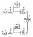
- FIG. 1is an exemplary illustration of a system 110 for remotely monitoring an individual 112 , in accordance with some embodiments of the invention.
- System 110may monitor one or more physiological functions and/or physical activities of individual 112 .
- System 110may include a laser radar system 116 capable of determining a range to and/or a range rate (i.e., velocity) of a point on a surface of individual 112 (e.g., skin, clothing, lips, etc.).
- System 110may include a monitor module 118 capable of monitoring one or more physiological functions and/or physical activities of individual 112 based on the determinations of laser radar system 116 .
- System 110may enable the physiological functions and/or physical activities to be monitored remotely from individual 112 without directly contacting individual 112 . In other words, monitoring the physiological functions and/or physical activities of individual 112 via system 110 may be accomplished in a manner that may be indiscernible to individual 112 .
- laser radar system 116may direct a beam of electromagnetic radiation 114 toward individual 112 to be incident on individual 112 at the point on the surface of individual 112 to be measured. Some or all of radiation 114 directed to the point on the surface of individual 112 may be reflected by the surface, and may then be received back into laser radar system 116 . As described below, based on one or more aspects of radiation 114 (e.g., frequency, phase, intensity, etc.) prior to emission and/or subsequent to reflection, laser radar system 116 may determine one or both of the range and the range rate of the point on the surface with respect to laser radar system 116 .
- radiation 114e.g., frequency, phase, intensity, etc.
- laser radar system 116may make a plurality of determinations of range and/or range rate of a point on a surface of individual 112 (e.g., at a periodic rate) over a period of time.
- Monitor module 118may implement the determined ranges and range rates to determine general trends in the ranges and/or range rates over the period of time, and residual deviations from the determined general trends.
- Monitor module 118may implement the determined general trends in the ranges and/or range rates to estimate body (or body member) motion, while the residual deviations from the determined trends may be used to estimate surface vibrations of the surface of individual 112 .
- the observed surface vibrationsmay include one or both of short period vibrations and long period vibrations. Based on the estimated body motion and/or surface vibrations, one or more physiological functions and/or physical activities of individual 112 may be monitored by monitor module 118 .
- ranges and/or range rates of a plurality of points on one or more surfaces of individual 112may be determined by laser radar system 116 .
- laser radar system 116may scan radiation 114 at emission such that the point at which radiation 114 is directed on individual 112 may be scanned across individual 112 in a raster.
- laser radar system 116may monitor one or more surface areas on individual 112 (e.g., a chest area, a neck area, a wrist area, a facial area, etc.), or laser radar system 116 may monitor the entire surface of individual 112 exposed on a line of sight to laser radar system 116 .
- the physiological functions and/or physical activities of individual 112 monitored by monitor module 118 based on the estimations of body motion and/or surface vibrations of individual 112may include one or more cardiovascular functions, one or more respiratory function, other physiological functions, and other physical activities.
- Cardiovascular functionsmay include a heart rate, a heart rate variability, a pulse transit time, a pulse shape, and/or other cardiovascular functions.
- Respiratory functionsmay include a respiration rate, a respiratory effort, and/or other respiratory functions.
- Physical activitiesmay include speaking, coughing, sneezing, walking, running, or other physical activities.
- the physiological functions and/or physical activitiesmay include one or more physiological functions which may be inferred from others of the physiological functions and/or physical activities. Examples of this may include, a vascular tone that may be inferred from a pulse transit time, and/or an autonomic tone that may be inferred from a pulse shape.
- FIG. 2illustrates a frequency modulated laser radar system 210 that may be implemented within system 110 as laser radar system 116 , according to some embodiments of the invention.
- System 210may include a laser source 212 that emits a beam 214 of electromagnetic radiation.
- Beam 214may be emitted at a frequency that is continuously varied, or chirped. In some instances, chirping the frequency may include sweeping the frequency between a lower frequency and an upper frequency (or vice versa) in a periodic manner (e.g. a sawtooth waveform, a triangle waveform, etc.).
- Beam 214may be divided by an optical coupler 216 into a target beam 218 and a reference beam 220 .
- system 210may include a target interferometer 222 and a reference interferometer 224 .
- Target interferometer 222may receive target beam 218 , and may divide the target beam at an optical coupler 226 .
- Target interferometer 222is typically used to generate a target signal that may depend upon a range of a target 230 (e.g. individual 112 ) from target interferometer 222 .
- Target interferometermay accomplish this by directing one portion 228 of target beam 218 toward target 230 , and the other portion 232 of target beam 218 to a target frequency difference module 234 over an optical path with a fixed path length.
- Portion 228 of target beam 218may be reflected by target 230 and may be transmitted to target frequency difference module 234 via optical coupler 226 and an optical fiber 236 . Based on interference between portions 236 and 232 at coupler 248 , target frequency difference module 234 may generate the target signal corresponding to a beat frequency of portions 236 and 232 of target beam 218 due to the difference between their path lengths.
- reference interferometer 224may receive reference beam 220 and may generate a reference signal corresponding to a frequency difference between two portions of reference beam 224 that may be directed over two separate fixed paths with a known path length difference. More particularly, reference beam 220 may be divided by an optical coupler 240 into a first portion 242 and a second portion 244 . First portion 242 may have a fixed optical path length difference relative to second portion 244 . Based on interference between portions 242 and 244 at coupler 246 , reference frequency difference module 250 may generate the reference signal corresponding to a beat frequency of portions 242 and 244 of reference beam 220 caused by the fixed difference between their path lengths.
- target interferometer 222 and reference interferometer 224have been illustrated and described as Mach-Zehnder interferometers. However other interferometer configurations may be utilized.
- target interferometer 222 and reference interferometer 224may include embodiments wherein Michelson-Morley interferometers may be formed.
- system 210may include a processor 238 .
- Processor 238may receive the target signal and the reference signal and may process these signals to determine the range of target 230 .
- Range information determined based on the target signal and the reference signalmay be used to determine a range rate of target 230 with respect to target interferometer 222 .
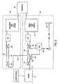
- FIG. 3illustrates an exemplary embodiment of a laser radar system 310 that may be implemented within system 110 , as laser radar system 116 , to monitor one or more points on a surface of individual 112 , according to some embodiments of the invention.
- Laser radar system 310may employ two or more laser radar sections, each of which emits a target beam of radiation toward a target.
- a first laser radar section 374emits a first target beam 312
- a second laser radar section 376emits a second target beam 314 toward a target 316 (e.g., individual 112 ).
- first target beam 312 and second target beam 314may be chirped to create a dual chirp system.
- the implementation of laser radar system 310 in system 110 to monitor one or more points on a surface of individual 112may provide unambiguous determinations of the range and the range rate of the points on the surface of individual 112 with respect to system 110 , and may enable enhanced monitoring of one or more physiological functions and/or physical activities of individual 112 by monitoring module 118 .
- the unambiguous determination of the range and/or the range rate of the points on the surface of individual 112may reduce an amount of noise in the determined ranges and/or range rates. If present, the noise may impact the accuracy of the determinations of the ranges and/or range rates.
- Inaccuracies within the determined ranges and/or range ratesmay hamper determinations that leverage the determined ranges and/or range rates to monitor physiological functions and/or physical activities of individual 112 , such as determinations of general trends in the ranges and/or range rates that indicate body motion, and/or residual deviation(s) from the general trends indicative of surface vibrations.
- laser section 374may include a laser source controller 336 , a first laser source 318 , a first optical coupler 322 , a first beam delay 344 , a first local oscillator optical coupler 330 , and/or other components.
- Second laser radar section 376may include a laser source controller 338 , a second laser source 320 , a second optical coupler 324 , a second beam delay 350 , a second local oscillator optical coupler 332 and/or other components.
- some or all of the components of each of laser radar sections 374 and 376may be obtained as a coherent laser radar system from Metris USA.
- Coherent laser radar systems from Metris USAmay provide various advantages, such as enhanced linearity functionality, enhanced phase wandering correction, and other advantages to laser radar system 310 in determining the range and the range rate of target 316 .
- first target beam 312 and second target beam 314may be reflected by target 316 back toward laser radar system 310 .
- Laser radar system 310may receive first target beam 312 and second target beam 314 , and may determine at least one of a range of target 316 from laser radar system 310 , and a range rate of target 316 .
- first laser source 318may have a first carrier frequency.
- First laser source 318may emit a first laser beam 340 at a first frequency.
- the first frequencymay be modulated at a first chirp rate.
- the first frequencymay be modulated electrically, mechanically, acousto-optically, or otherwise modulated as would be apparent.
- First laser beam 340may be divided by first optical coupler 322 into first target beam 312 and a first local oscillator beam 342 .
- First local oscillator beam 342may be held for a first delay period at a first beam delay 344 .
- second laser source 320may emit a second laser beam 346 at a second frequency.
- the second frequencymay be modulated at a second chirp rate different from the first chirp rate.
- the second frequencymay be modulated electrically, mechanically, acousto-optically, or otherwise modulated.
- the first chirp rate and the second chirp ratemay create a counter chirp between first laser beam 340 and second laser beam 346 .
- the second carrier frequencymay be substantially the same as the first carrier frequency.
- the percentage difference between the first baseline frequency and the second baseline frequencyis less than 0.05%.
- Second laser beam 346may be divided by second optical coupler 324 into a second target beam 314 and a second local oscillator beam 348 .
- Second local oscillator beam 348may be held for a second delay period at a second beam delay 350 .
- the second delay periodmay be different than the first delay period.
- the output(s) of first laser source 318 and/or second laser source 320may be linearized using mechanisms provided in, for example, Metris USA Model MV200. Phase wandering of the output(s) of first laser source 318 and/or second laser source 320 may be corrected using mechanisms provided in, for instance, Metris USA Model MV200.
- laser radar system 310may determine the range and the range rate of target 316 with an increased accuracy when the range of target 316 from laser radar system 310 falls within a set of ranges between a minimum range and a maximum range. When the range of target 316 does not fall within the set of ranges, the accuracy of laser radar system 310 may be degraded.
- first beam delay 344 and second beam delay 350may be adjustable. Adjusting first beam delay 344 and second beam delay 350 may enable laser radar system 310 to be adjusted to bring the set of ranges over which more accurate determinations may be made closer to, or further away from, laser radar system 310 . First beam delay 344 and the second beam delay 350 may be adjusted to ensure that the range of target 316 falls within the set of ranges between the minimum range and the maximum range so that the range and the range rate of target 316 may be determined accurately. First beam delay 344 and second beam delay 350 may be adjusted by a user, or in an automated manner.
- the degradation of determinations of range and range rate when the range of target 316 is outside of the set of rangesmay be a result of the finite nature of the coherence length of first laser source 318 and second laser source 320 .
- the distance between the minimum range and the maximum rangemay be a function of the coherence length.
- the longer the coherence length of first laser source 318 and second laser source 320the greater the distance between the minimum range and the maximum range may be.
- increasing the coherence length of first laser source 318 and second laser source 320may enhance range and range rate determinations by laser radar system 310 by providing the ability to make determinations over an enhanced set of ranges.
- first local oscillator beam 342may be divided into a plurality of first local oscillator beams and second local oscillator beam 348 may be divided into a plurality of second local oscillator beams.
- laser radar system 310may include a plurality of beam delays that may apply delays of varying delay periods to the plurality of first local oscillator beams and the plurality of second local oscillator beams. This may ensure that one of the plurality of first local oscillator beams and one of the plurality of second local oscillator beams may have been delayed for delay periods that may enable the range and range rate of the target to be determined accurately.
- first laser source 318 and second laser source 320may emit chirped electromagnetic radiation with an enhanced coherence length.
- first laser source 318 and/or second laser source 320may include system 310 as illustrated in FIG. 3 and described above.
- first target beam 312 and second target beam 314may be directed and/or received from target 316 on separate optical paths. In some embodiments, these optical paths may be similar but distinct. In other embodiments, first target beam 312 and second target beam 314 may be coupled by a target optical coupler 326 into a combined target beam 352 prior to emission that may be directed toward target 316 along a common optical path. In some embodiments, combined target beam 352 (or first target beam 312 and second target beam 314 , if directed toward target 316 separately) may be reflected by target 316 and may be received by laser radar system 310 along a reception optical path separate from the common optical path that directed combined target beam 352 toward target 316 .
- the common optical pathmay include optical member 328 that may provide a common port for emitting combined target beam 352 and receiving reflected target beam 356 .
- Optical member 328may include an optical circulator, an optical coupler or other optical member as would be apparent.
- the common optical pathmay include a scanning element 337 .
- Scanning element 337may include an optical element such as, for instance, a mirror, a lens, an antenna, or other optical elements that may be oscillated, rotated, or otherwise actuated to enable combined target beam 352 to scan target 316 .
- scanning element 337may enable scanning at high speeds.
- scanning elementsmay be a source of mirror differential Doppler noise effects due to speckle or other optical effects that may degrade the accuracy of these systems.
- simultaneous measurementsor substantially so
- a target optical coupler 354may divide reflected target beam 356 into a first reflected target beam portion 358 and a second reflected target beam portion 360 .
- First local oscillator optical coupler 330may combine first local oscillator beam 342 with first reflected target beam portion 358 into a first combined target beam 362 .
- Second local oscillator optical coupler 332may combine second local oscillator beam 348 with second reflected target beam portion 360 into a second combined target beam 364 .
- first local oscillator optical coupler 330may combine first target beam 312 that is reflected with first local oscillator beam 342 to create first combined target beam 362 , and second target beam 314 that is reflected may be combined with second local oscillator beam 348 to create second combined target beam 364 .
- first combined target beam 362 and second combined target beam 364may represent optical signals that might be present in two separate, but coincident, single laser source frequency modulated laser radar systems, just prior to final processing.
- laser source controller 336 , first laser source 318 , first optical coupler 322 , first beam delay 344 , and first local oscillator optical coupler 330may be viewed as a first laser radar section 374 that may generate first combined target beam 362 separate from second combined target beam 364 that may be generated by a second laser radar section 376 .
- Second laser radar section 376may include laser source controller 338 , second laser source 320 , second optical coupler 324 , second beam delay 350 , and second local oscillator optical coupler 332 .
- laser radar system 310may include a processor 334 .
- Processor 334may include a detection module 366 , a mixing module 368 , a processing module 370 , and/or other modules. The modules may be implemented in hardware (including optical and detection components), software, firmware, or a combination of hardware, software, and/or firmware.
- Processor 334may receive first combined target beam 362 and second combined target beam 364 . Based on first combined target beam 362 and second combined target beam 364 , processor 334 may generate the range signal and the range rate signal. Based on the range signal and the range rate signal, the range and the range rate of target 316 may be unambiguously determined.
- processor 334may determine a first beat frequency of first combined local oscillator beam 362 .
- the first beat frequencymay include a difference in frequency, attributable to a difference in path length, of first local oscillator beam 342 and the component of reflected target beam 356 that corresponds to first target beam 312 that has been reflected from target 316 .
- Processor 334may determine a second beat frequency of second combined local oscillator beam 364 .
- the second beat frequencymay include a difference in frequency, attributable to a difference in path length, of second local oscillator beam 348 and the component of reflected target beam 356 that corresponds to second target beam 314 that has been reflected from target 316 .
- the first beat frequency and the second beat frequencymay be determined simultaneously (or substantially so) to cancel noise introduced by environmental or other effects.
- One or more stepsmay be taken to enable the first beat frequency and the second beat frequency to be distinguished from other frequency components within first combined target beam 362 , other frequency components within second combined target beam 364 , and/or each other.
- these measuresmay include using two separate chirp rates as the first chirp rate and the second chirp rate, delaying first local oscillator beam 342 and second local oscillator beam 350 for different delay times at first beam delay 344 and second beam delay 350 , respectively, or other measures may be taken.
- FIG. 3illustrates an exemplary embodiment of the invention implemented primarily using optical fibers and optical couplers
- this embodimentis in no way intended to be limiting.
- other optical elementssuch as, for example, prisms, mirrors, half-mirrors, beam splitters, dichroic films, dichroic prisms, lenses, or other optical elements may be used to direct, combine, direct, focus, diffuse, amplify, or otherwise process electromagnetic radiation.
- processor 334may mix first combined target beam 362 and second combined target beam 364 to produce a mixed signal.
- the mixed signalmay include a beat frequency sum component that may correspond to the sum of the first beat frequency and the second beat frequency, and a beat frequency difference component that may correspond to the difference between the first beat frequency and the second beat frequency.
- first laser beam 340 and second laser beam 346 beat frequenciesmay be described as follows:
- f 1 ⁇ ( t )4 ⁇ ⁇ ⁇ ⁇ v ⁇ 1 + 2 ⁇ ⁇ 1 ⁇ ( R - RO 1 )
- f 2 ⁇ ( t )4 ⁇ ⁇ ⁇ ⁇ v ⁇ 2 + 2 ⁇ ⁇ 2 ⁇ ( R - RO 2 ) , respectively
- f 1 (t)represents the first beat frequency
- f 2 (t)represents the second beat frequency
- ⁇ 1 and ⁇ 2are the two optical wavelengths
- vis the target velocity
- ⁇ 1 and ⁇ 2are proportional to the respective chirp rates
- Ris the measured range
- RO 1 and RO 2represent the range offsets for the two laser radars.
- v⁇ 4 ⁇ ⁇ ⁇ ( f 1 ⁇ ( t ) - ⁇ 1 ⁇ 2 ⁇ f 2 ⁇ ( t ) 1 - ⁇ 1 ⁇ 2 ) + ⁇ ⁇ ⁇ y 1 2 ⁇ ( RO 1 - RO 2 1 - ⁇ 1 ⁇ 2 ) , ( 5 ) which provides a measure of the target velocity.
- the beat frequency sum componentmay be filtered from the mixed signal to produce a range signal.
- a determination of the distance from laser radar system 310 to target 316may be made.
- the determination based on the range signalmay be unambiguous, and may not depend on either the instantaneous behavior, or the average behavior of the Doppler frequency shift (e.g. v/ ⁇ ).
- the beat frequency difference componentmay be filtered from the mixed signal to produce a range rate signal. From the beat frequency difference component included in the range rate signal, a determination of the range rate of target 316 may be unambiguously made. To determine the range rate of target 316 ,
- f 1 ⁇ ( t ) - ⁇ 1 ⁇ 2 ⁇ f 2 ⁇ ( t )may be represented as a value proportional to a chirp rate difference between the first chirp rate and the second chirp rate. This may enable the Doppler shift information to be extracted, which may represent an instantaneous velocity (i.e., range rate) of target 316 .
- the second chirp ratemay be set to zero.
- second laser source 318may emit radiation at a constant frequency. This may enable second laser source 318 to be implemented with a simpler design, a small footprint, a lighter weight, a decreased cost, or other enhancements that may provide advantages to the overall system.
- laser radar system 310may include a frequency shifting device.
- the frequency shifting devicemay include an acousto-optical modulator 372 , or other device.
- Acousto-optical modulator 372may provide a frequency offset to second local oscillator beam 348 , which may enhance downstream processing.
- the frequency offsetmay enable a stationary target beat frequency between second local oscillator beam 348 and second reflected target beam portion 360 representative of a range rate of a stationary target to be offset from zero so that the a direction of the target's movement, as well as a magnitude of the rate of the movement, may be determined from the beat frequency.
- This embodiment of the inventionhas the further advantage that it may allow for continuous monitoring of the target range rate, uninterrupted by chirp turn-around or fly-back. Chirp turn-around or fly-back may create time intervals during which accurate measurements may be impossible for a chirped laser radar section.
- laser radar section 376may only determine the range rate of target 316 while laser radar system 310 retains the ability to measure both range and range rate.
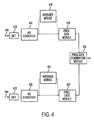
- FIG. 4illustrates a processor 334 according to one embodiment of the invention.
- Processor 334may mix first combined target beam 362 and second combined target beam 364 digitally.
- processor 334may include a first detector 410 and a second detector 412 .
- the first detector 410may receive first combined target beam 362 and may generate a first analog signal that corresponds to first combined target beam 362 .
- the first analog signalmay be converted to a first digital signal by a first converter 414 .
- Processor 334may include a first frequency data module 416 that may determine a first set of frequency data that corresponds to one or more frequency components of the first digital signal.
- the first digital signalmay be averaged at a first averager module 418 . In such instances, the averaged first digital signal may then be transmitted to first frequency data module 416 .
- Second detector 412may receive second combined target beam 364 and may generate a second analog signal that corresponds to second combined target beam 364 .
- the second analog signalmay be converted to a second digital signal by a second converter 420 .
- Processor 334may include a second frequency data module 422 that may determine a second set of frequency data that corresponds to one or more of frequency components of the second digital signal.
- the second digital signalmay be averaged at a second averager module 424 . In such instances, the averaged second digital signal may then be transmitted to second frequency data module 422 .
- the first set of frequency data and the second set of frequency datamay be received by a frequency data combination module 426 .
- Frequency data combination module 426may linearly combine the first set of frequency data and the second set of frequency data, and may generate a range rate signal and a range signal derived from the mixed frequency data.
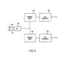
- FIG. 5illustrates a processor 334 according to another embodiment of the invention.
- Processor 334may include a first detector 510 and a second detector 512 that may receive first combined target beam 362 and second combined target beam 364 , respectively.
- First detector 510 and second detector 512may generate a first analog signal and a second analog signal associated with first combined target beam 362 and second combined target beam 364 , respectively.
- Processor 334may mix first combined target beam 362 and second combined target beam 364 electronically to generate the range signal and the range rate signal.
- processor 334may include a modulator 514 .
- Modulator 514may multiply the first analog signal generated by first detector 510 and the second analog signal generated by second detector 512 to create a combined analog signal.
- processor 334may include a first filter 516 and a second filter 518 that receive the combined analog signal.
- First filter 516may filter the combined analog signal to generate a first filtered signal.
- first filter 516may include a low-pass filter.
- the first filtered signalmay be converted by a first converter 520 to generate the range rate signal.
- Second filter 518may filter the combined analog signal to generate a second filtered signal.
- second filter 518may include a high-pass filter.
- the second filtered signalmay be converted by a second converter 522 to generate the range signal.
- FIG. 6illustrates a processor 334 according to yet another embodiment of the invention.
- Processor 334may mix first combined target beam 362 and second combined target beam 364 optically to generate the range signal and the range rate signal.
- processor 334may include a detector 610 that receives first combined target beam 362 and second combined target beam 364 and generates a combined analog signal based on the detection.
- processor 334may include a first filter 612 and a second filter 614 that receive the combined analog signal.
- First filter 612may filter the combined analog signal to generate a first filtered signal.
- First filter 612may include a low-pass filter.
- the first filtered signalmay be converted by a first converter 616 to generate the range rate signal.
- Second filter 614may filter the combined analog signal to generate a second filtered signal.
- Second filter 14may include a high-pass filter.
- the second filtered signalmay be converted by a second converter 618 to generate the range signal.
Landscapes
- Health & Medical Sciences (AREA)
- Life Sciences & Earth Sciences (AREA)
- Heart & Thoracic Surgery (AREA)
- Surgery (AREA)
- Physics & Mathematics (AREA)
- Veterinary Medicine (AREA)
- Biophysics (AREA)
- Pathology (AREA)
- Engineering & Computer Science (AREA)
- Biomedical Technology (AREA)
- Public Health (AREA)
- Medical Informatics (AREA)
- Molecular Biology (AREA)
- General Health & Medical Sciences (AREA)
- Animal Behavior & Ethology (AREA)
- Oral & Maxillofacial Surgery (AREA)
- Physiology (AREA)
- Dentistry (AREA)
- Nuclear Medicine, Radiotherapy & Molecular Imaging (AREA)
- Radiology & Medical Imaging (AREA)
- Optical Radar Systems And Details Thereof (AREA)
- Measurement Of The Respiration, Hearing Ability, Form, And Blood Characteristics Of Living Organisms (AREA)
- Measuring And Recording Apparatus For Diagnosis (AREA)
Abstract
Description
where f1(t) represents the first beat frequency, f2(t) represents the second beat frequency, λ1and λ2are the two optical wavelengths, v is the target velocity, γ1and γ2are proportional to the respective chirp rates, R is the measured range and RO1and RO2represent the range offsets for the two laser radars. Now assume that λ1=λ2=λ. We may subtract the equations to yield
Rearranging (3) we obtain
as the corrected range measurement. Similarly we may combine (1) and (2) to obtain the expression,
which provides a measure of the target velocity.
may be represented as a value proportional to a chirp rate difference between the first chirp rate and the second chirp rate. This may enable the Doppler shift information to be extracted, which may represent an instantaneous velocity (i.e., range rate) of
Claims (14)
Priority Applications (3)
| Application Number | Priority Date | Filing Date | Title |
|---|---|---|---|
| US12/393,537US9872639B2 (en) | 2004-09-21 | 2009-02-26 | System and method for remotely monitoring physiological functions |
| US15/864,645US20180184946A1 (en) | 2004-09-21 | 2018-01-08 | System and Method for Remotely Monitoring Physiological Functions |
| US17/175,756US11937916B2 (en) | 2004-09-21 | 2021-02-15 | System and method for remotely monitoring physiological functions |
Applications Claiming Priority (4)
| Application Number | Priority Date | Filing Date | Title |
|---|---|---|---|
| US61129504P | 2004-09-21 | 2004-09-21 | |
| US65198905P | 2005-02-14 | 2005-02-14 | |
| US11/230,546US7507203B2 (en) | 2004-09-21 | 2005-09-21 | System and method for remotely monitoring physiological functions |
| US12/393,537US9872639B2 (en) | 2004-09-21 | 2009-02-26 | System and method for remotely monitoring physiological functions |
Related Parent Applications (1)
| Application Number | Title | Priority Date | Filing Date |
|---|---|---|---|
| US11/230,546ContinuationUS7507203B2 (en) | 2004-09-21 | 2005-09-21 | System and method for remotely monitoring physiological functions |
Related Child Applications (1)
| Application Number | Title | Priority Date | Filing Date |
|---|---|---|---|
| US15/864,645ContinuationUS20180184946A1 (en) | 2004-09-21 | 2018-01-08 | System and Method for Remotely Monitoring Physiological Functions |
Publications (2)
| Publication Number | Publication Date |
|---|---|
| US20090216093A1 US20090216093A1 (en) | 2009-08-27 |
| US9872639B2true US9872639B2 (en) | 2018-01-23 |
Family
ID=36090583
Family Applications (4)
| Application Number | Title | Priority Date | Filing Date |
|---|---|---|---|
| US11/230,546Expired - LifetimeUS7507203B2 (en) | 2004-09-21 | 2005-09-21 | System and method for remotely monitoring physiological functions |
| US12/393,537Active2027-08-17US9872639B2 (en) | 2004-09-21 | 2009-02-26 | System and method for remotely monitoring physiological functions |
| US15/864,645AbandonedUS20180184946A1 (en) | 2004-09-21 | 2018-01-08 | System and Method for Remotely Monitoring Physiological Functions |
| US17/175,756Active2027-01-21US11937916B2 (en) | 2004-09-21 | 2021-02-15 | System and method for remotely monitoring physiological functions |
Family Applications Before (1)
| Application Number | Title | Priority Date | Filing Date |
|---|---|---|---|
| US11/230,546Expired - LifetimeUS7507203B2 (en) | 2004-09-21 | 2005-09-21 | System and method for remotely monitoring physiological functions |
Family Applications After (2)
| Application Number | Title | Priority Date | Filing Date |
|---|---|---|---|
| US15/864,645AbandonedUS20180184946A1 (en) | 2004-09-21 | 2018-01-08 | System and Method for Remotely Monitoring Physiological Functions |
| US17/175,756Active2027-01-21US11937916B2 (en) | 2004-09-21 | 2021-02-15 | System and method for remotely monitoring physiological functions |
Country Status (7)
| Country | Link |
|---|---|
| US (4) | US7507203B2 (en) |
| EP (1) | EP1814443B1 (en) |
| JP (1) | JP5227023B2 (en) |
| CN (1) | CN101394783B (en) |
| AU (1) | AU2005286872B2 (en) |
| CA (1) | CA2579100C (en) |
| WO (1) | WO2006034211A2 (en) |
Families Citing this family (42)
| Publication number | Priority date | Publication date | Assignee | Title |
|---|---|---|---|---|
| AU2005286872B2 (en)* | 2004-09-21 | 2012-03-08 | Digital Signal Corporation | System and method for remotely monitoring physiological functions |
| US7511824B2 (en) | 2005-02-14 | 2009-03-31 | Digital Signal Corporation | Chirped coherent laser radar system and method |
| CA2634033C (en) | 2005-12-14 | 2015-11-17 | Digital Signal Corporation | System and method for tracking eyeball motion |
| US8081670B2 (en) | 2006-02-14 | 2011-12-20 | Digital Signal Corporation | System and method for providing chirped electromagnetic radiation |
| JP2007255977A (en)* | 2006-03-22 | 2007-10-04 | Nissan Motor Co Ltd | Object detection method and object detection apparatus |
| US8920343B2 (en) | 2006-03-23 | 2014-12-30 | Michael Edward Sabatino | Apparatus for acquiring and processing of physiological auditory signals |
| JP4818035B2 (en)* | 2006-09-19 | 2011-11-16 | 株式会社タニタ | Calorie consumption measuring device for sleep |
| WO2009009722A2 (en) | 2007-07-12 | 2009-01-15 | University Of Florida Research Foundation, Inc. | Random body movement cancellation for non-contact vital sign detection |
| EP2128561B1 (en)* | 2008-05-28 | 2014-10-29 | Leica Geosystems AG | Interferometric distance measuring method with delayed chirp signal and such a device |
| US8687173B2 (en) | 2008-09-11 | 2014-04-01 | Nikon Metrology N.V. | Compact fiber optic geometry for a counter chirp FMCW coherent laser radar |
| AU2010257107B2 (en)* | 2009-02-20 | 2015-07-09 | Digital Signal Corporation | System and method for generating three dimensional images using lidar and video measurements |
| ES2426971T3 (en) | 2009-03-06 | 2013-10-28 | Koninklijke Philips N.V. | Image processing of at least one living being |
| CN102341811B (en) | 2009-03-06 | 2015-04-29 | 皇家飞利浦电子股份有限公司 | Method of controlling function of device and system for detecting presence of living being |
| JP4338770B1 (en)* | 2009-03-27 | 2009-10-07 | 株式会社大精電子製作所 | Human body abnormality determination device |
| WO2011042851A1 (en) | 2009-10-06 | 2011-04-14 | Koninklijke Philips Electronics N.V. | Method and system for carrying out photoplethysmography |
| JP5685598B2 (en) | 2009-10-06 | 2015-03-18 | コーニンクレッカ フィリップス エヌ ヴェ | Formation of a time-varying signal representing at least a change in value based on the pixel value |
| JP5682504B2 (en)* | 2010-09-09 | 2015-03-11 | コニカミノルタ株式会社 | Safety monitoring device |
| JP5686342B2 (en)* | 2011-01-28 | 2015-03-18 | 国立大学法人東北大学 | Laser radar device and laser synthetic aperture radar device |
| EP2678709B1 (en) | 2011-02-21 | 2018-03-28 | Transrobotics, Inc. | System and method for sensing distance and/or movement |
| US8947644B2 (en)* | 2012-01-19 | 2015-02-03 | Raytheon Company | Using multiple waveforms from a coherent LADAR for target acquisition |
| CN102657521B (en)* | 2012-05-07 | 2014-08-06 | 复旦大学 | Full optical fiber heart rate measuring equipment |
| US20150164379A1 (en)* | 2012-05-23 | 2015-06-18 | University Of Florida Research Foundation, Incorporated | Method and apparatus for detecting and/or analyzing motion using radar and multiple identifiable reflectors |
| DE102012218112B4 (en)* | 2012-10-04 | 2025-08-28 | Robert Bosch Gmbh | Method and device for determining the pulse rate |
| EP3828591A1 (en) | 2012-10-05 | 2021-06-02 | Transrobotics, Inc. | Systems and methods for high resolution distance sensing and applications |
| US9445220B2 (en)* | 2013-09-06 | 2016-09-13 | Paypal, Inc. | Systems and methods for enabling additional devices to check in to bluetooth low energy (BLE) beacons |
| US10012734B2 (en) | 2014-05-21 | 2018-07-03 | DSCG Solutions, Inc. | Devices, systems, and methods for real time tracking of an object |
| US11051702B2 (en) | 2014-10-08 | 2021-07-06 | University Of Florida Research Foundation, Inc. | Method and apparatus for non-contact fast vital sign acquisition based on radar signal |
| US10502833B2 (en) | 2015-01-13 | 2019-12-10 | DSCG Solutions, Inc. | Multiple beam range measurement process |
| US9833200B2 (en) | 2015-05-14 | 2017-12-05 | University Of Florida Research Foundation, Inc. | Low IF architectures for noncontact vital sign detection |
| WO2017088007A1 (en)* | 2015-11-25 | 2017-06-01 | Vac Group Operations Pty Ltd | Worksite safety device using lidar |
| RU2017128430A (en)* | 2015-12-22 | 2019-02-11 | Конинклейке Филипс Н.В. | DEVICE, SYSTEM AND METHOD FOR ASSESSING HUMAN ENERGY CONSUMPTION |
| US11428797B2 (en) | 2017-01-06 | 2022-08-30 | Carrier Corporation | Radar detection system |
| CN106974623A (en)* | 2017-04-27 | 2017-07-25 | 上海迈鹊医用机器人技术有限公司 | Blood vessel identification lancing system, blood vessel recognition methods |
| TWI609192B (en)* | 2017-05-26 | 2017-12-21 | 國立中山大學 | Vital sign monitoring system |
| JP7284808B2 (en)* | 2018-05-10 | 2023-05-31 | アワーズ テクノロジー リミテッド ライアビリティー カンパニー | A LIDAR system based on multi-channel laser modules for simultaneous beam scanning of a target environment |
| JP7107268B2 (en) | 2019-04-03 | 2022-07-27 | 日本製鉄株式会社 | Velocity measuring method and velocity measuring device |
| US11703593B2 (en) | 2019-04-04 | 2023-07-18 | TransRobotics, Inc. | Technologies for acting based on object tracking |
| US11788830B2 (en) | 2019-07-09 | 2023-10-17 | Apple Inc. | Self-mixing interferometry sensors used to sense vibration of a structural or housing component defining an exterior surface of a device |
| US11877105B1 (en) | 2020-05-18 | 2024-01-16 | Apple Inc. | Phase disparity correction for image sensors |
| CN112472481A (en)* | 2020-12-15 | 2021-03-12 | 沈阳工业大学 | Dynamic human body pose recognition embedded platform under trunk shielding state |
| US12379199B2 (en) | 2021-09-09 | 2025-08-05 | Apple Inc. | Vernier scan architecture for self-mixing interferometry phase measurements |
| US11854568B2 (en)* | 2021-09-16 | 2023-12-26 | Apple Inc. | Directional voice sensing using coherent optical detection |
Citations (111)
| Publication number | Priority date | Publication date | Assignee | Title |
|---|---|---|---|---|
| US3363248A (en) | 1966-02-17 | 1968-01-09 | Army Usa | Chirp radar technique for suppressing second time around echoes |
| US3611182A (en) | 1968-11-19 | 1971-10-05 | United Aircraft Corp | Optical chirp pulse generator |
| US4100498A (en) | 1977-06-20 | 1978-07-11 | The United States Of America As Represented By The Secretary Of The Navy | Discrete chirp frequency synthesizer |
| US4153900A (en) | 1967-12-20 | 1979-05-08 | Rockwell International Corporation | Phase-coded pulse compression type pulsed energy system |
| US4272193A (en) | 1979-04-13 | 1981-06-09 | The United States Of America As Represented By The United States Department Of Energy | Method and apparatus for timing of laser beams in a multiple laser beam fusion system |
| US4314210A (en) | 1979-11-23 | 1982-02-02 | Jersey Nuclear-Avco Isotopes, Inc. | Mode-locking and chirping system for lasers |
| US4319807A (en) | 1980-03-24 | 1982-03-16 | Jersey Nuclear-Avco Isotopes, Inc. | Rotating optical frequency chirp device |
| US4333080A (en) | 1977-07-18 | 1982-06-01 | Raytheon Company | Signal processor |
| US4339954A (en) | 1978-03-09 | 1982-07-20 | National Research Development Corporation | Measurement of small movements |
| US4532603A (en) | 1983-03-09 | 1985-07-30 | The United States Of America As Represented By The Secretary Of The Army | Chirp transform correlator |
| US4537503A (en)* | 1981-12-22 | 1985-08-27 | Atomic Energy Of Canada Limited | Multiple measuring control volume laser doppler anemometer |
| US4578677A (en) | 1983-09-23 | 1986-03-25 | The United States Of America As Represented By The Secretary Of The Navy | Range doppler coupling magnifier |
| US4662741A (en) | 1983-03-17 | 1987-05-05 | Hughes Aircraft Company | Linear FM chirp laser |
| US4664129A (en) | 1985-04-15 | 1987-05-12 | U.S. Philips Corporation | Optical movement sensor |
| US4666295A (en) | 1983-03-17 | 1987-05-19 | Hughes Aircraft Company | Linear FM chirp laser |
| US4697888A (en) | 1982-04-21 | 1987-10-06 | Chevron Research Company | Frequency shifted cavity for electromagnetic radiation |
| US4743110A (en) | 1983-03-29 | 1988-05-10 | Thomson Csf | Laser telemetry and Doppler measurement system with pulse compression |
| US4822164A (en)* | 1987-09-30 | 1989-04-18 | Eaton Corporation | Optical inspection device and method |
| DE3807077A1 (en) | 1987-10-02 | 1989-04-20 | Bochumer Eisen Heintzmann | Device for the contactless optical measurement of distance according to the triangulation method |
| US4830486A (en) | 1984-03-16 | 1989-05-16 | Goodwin Frank E | Frequency modulated lasar radar |
| US4849760A (en) | 1987-11-20 | 1989-07-18 | Unisys Corporation | Surface acoustic wave doppler detector |
| EP0347215A2 (en) | 1988-06-17 | 1989-12-20 | Digital Signal Corporation | Proximity sensor |
| US4945916A (en) | 1986-10-14 | 1990-08-07 | Thomson-Csf | Optical device for the simultaneous detection of heart and respiratory movements |
| EP0389720A1 (en) | 1989-03-28 | 1990-10-03 | Canadian Marconi Company | Radar detection of targets at short and long range |
| US5101291A (en) | 1990-12-28 | 1992-03-31 | At&T Bell Laboratories | Optical frequency conversion device |
| US5106192A (en)* | 1990-03-16 | 1992-04-21 | Eastman, Inc. | Polarization insensitive absolute interferometeric method and apparatus for measuring position angular bearing and optical paths |
| US5107846A (en) | 1989-08-31 | 1992-04-28 | Dan Atlas | Displacement detector device and method |
| JPH0587823A (en) | 1991-03-29 | 1993-04-06 | Raytheon Co | Device and method of detecting direction of wind |
| JPH05281342A (en) | 1992-03-31 | 1993-10-29 | Toshiba Corp | Radar equipment |
| US5283795A (en) | 1992-04-21 | 1994-02-01 | Hughes Aircraft Company | Diffraction grating driven linear frequency chirped laser |
| US5289252A (en) | 1992-12-08 | 1994-02-22 | Hughes Aircraft Company | Linear frequency modulation control for FM laser radar |
| US5298962A (en) | 1992-11-05 | 1994-03-29 | Hughes Aircraft Company | Pulse compression signal processor utilizing identical saw matched filters for both up and down chirps |
| US5371587A (en)* | 1992-05-06 | 1994-12-06 | The Boeing Company | Chirped synthetic wavelength laser radar |
| US5428361A (en) | 1993-08-06 | 1995-06-27 | Rockwell International Corporation | Large time-bandwidth chirp pulse generator |
| WO1995027453A1 (en) | 1994-04-08 | 1995-10-19 | Chiron/Technolas Gmbh Ophthalmologische Systeme | Method and apparatus for providing precise location of points on the eye |
| US5477324A (en)* | 1994-08-26 | 1995-12-19 | Georgia Tech Research Corporation | Method and apparatus for detecting surface wave vector dynamics using three beams of coherent light |
| US5508759A (en) | 1991-01-08 | 1996-04-16 | Canon Kabushiki Kaisha | Visual axis detection apparatus |
| NL9401514A (en) | 1994-09-19 | 1996-05-01 | Eyelight Research Nv | Method and apparatus for measuring the visual attention of persons or animals to a visible object |
| US5521930A (en) | 1994-07-19 | 1996-05-28 | Suni; Paul J. M. | Device for injection-seeding, frequency-shifting, and q-switching a laser source |
| US5632742A (en) | 1994-04-25 | 1997-05-27 | Autonomous Technologies Corp. | Eye movement sensing method and system |
| US5644642A (en) | 1995-04-03 | 1997-07-01 | Carl Zeiss, Inc. | Gaze tracking using optical coherence tomography |
| US5647360A (en) | 1995-06-30 | 1997-07-15 | Siemens Corporate Research, Inc. | Digital subtraction angiography for 3D diagnostic imaging |
| US5715166A (en) | 1992-03-02 | 1998-02-03 | General Motors Corporation | Apparatus for the registration of three-dimensional shapes |
| US5777892A (en)* | 1992-03-30 | 1998-07-07 | Isco, Inc. | Doppler shift velocity measuring system with correction factors |
| US5781295A (en) | 1995-08-04 | 1998-07-14 | Carl Zeiss Jena Gmbh | Interferometer for absolute distance measurement |
| JPH10268369A (en) | 1997-03-21 | 1998-10-09 | Imra America Inc | Optical pulse amplifier, chirped pulse amplifier, and parametric chirped pulse amplifier |
| WO1999018868A1 (en) | 1997-10-10 | 1999-04-22 | Visx Incorporated | Eye tracking device for laser eye surgery using corneal margin detection |
| US5903358A (en) | 1997-06-20 | 1999-05-11 | The Board Of Trustees Of The Leland Stanford Junior University | Spectroscopy using active diode laser stabilization by optical feedback |
| US5949546A (en) | 1997-05-14 | 1999-09-07 | Ahead Optoelectronics, Inc. | Interference apparatus for measuring absolute and differential motions of same or different testing surface |
| WO2000024467A1 (en) | 1998-10-23 | 2000-05-04 | Varian Medical Systems, Inc. | Method and system for physiological gating of radiation therapy |
| US6062216A (en) | 1996-12-27 | 2000-05-16 | Children's Medical Center Corporation | Sleep apnea detector system |
| WO2000031899A1 (en) | 1998-11-24 | 2000-06-02 | Hughes Electronics Corporation | Synchronization in mobile satellite systems using dual-chirp waveform |
| US6080990A (en) | 1997-03-21 | 2000-06-27 | Kabushiki Kaisha Topcon | Position measuring apparatus |
| US6120461A (en) | 1999-08-09 | 2000-09-19 | The United States Of America As Represented By The Secretary Of The Army | Apparatus for tracking the human eye with a retinal scanning display, and method thereof |
| US6133993A (en)* | 1998-01-26 | 2000-10-17 | Trw Inc. | Length and velocity measurement apparatus |
| US6191862B1 (en) | 1999-01-20 | 2001-02-20 | Lightlab Imaging, Llc | Methods and apparatus for high speed longitudinal scanning in imaging systems |
| US20010009458A1 (en) | 2000-01-20 | 2001-07-26 | Kimio Asaka | Coherent laser radar system and target measurement method |
| US20010016733A1 (en) | 1994-04-25 | 2001-08-23 | Frey Rudolph W. | Method of correcting vision |
| JP2001267667A (en) | 2000-03-23 | 2001-09-28 | Nippon Telegr & Teleph Corp <Ntt> | Frequency shift feedback mode-locked laser and frequency shift feedback mode-locked laser. |
| WO2001085024A1 (en) | 2000-05-10 | 2001-11-15 | Motorola, Inc., | Optical noninvasive blood pressure sensor and method |
| US6328698B1 (en) | 1998-08-18 | 2001-12-11 | Hiroshi Matsumoto | Diagnostic system and method for coronary artery disease and others |
| US20020016533A1 (en) | 2000-05-03 | 2002-02-07 | Marchitto Kevin S. | Optical imaging of subsurface anatomical structures and biomolecules |
| US20020024331A1 (en) | 2000-04-17 | 2002-02-28 | Harvey Lewis | Method of investigating vibrations and an apparatus therefor |
| US6364838B1 (en)* | 2000-01-11 | 2002-04-02 | Siemens Medical Soulutions, Usa, Inc. | Pulsed wave doppler processing using aliased spectral data |
| US6390978B1 (en)* | 1999-10-01 | 2002-05-21 | Karl Storz Gmbh & Co. Kg | Imaging method for determining a physical or chemical condition of tissue in human or animal bodies, and system for carrying out the method |
| US6445942B1 (en) | 1999-09-15 | 2002-09-03 | Resmed Ltd | Measurement of respiratory effort using a suprasternal sensor |
| EP1258719A1 (en) | 2000-02-21 | 2002-11-20 | Japan Science and Technology Corporation | Polarization mode dispersion measuring device and polarization mode dispersion measuring method |
| US20030023171A1 (en)* | 2000-02-03 | 2003-01-30 | Katsuhiko Sato | Noninvasion biological optical measuring instrument, measured portion holding device, and method for manufacturing the same |
| US20030034387A1 (en) | 1999-06-07 | 2003-02-20 | Metrologic Instruments, Inc. | Object identification and attribute information acquisition and linking computer system |
| US20030043467A1 (en) | 2001-08-28 | 2003-03-06 | Harald Rosenfeldt | Polarization delay unit |
| US20030052169A1 (en) | 1999-06-07 | 2003-03-20 | Metrologic Instruments, Inc. | Planar laser illumination and imaging (PLIIM) based camera system for producing high-resolution 3-D images of moving 3-D objects |
| US6556854B1 (en) | 1998-11-20 | 2003-04-29 | Fuji Photo Film Co., Ltd. | Blood vessel imaging system using homodyne and heterodyne effects |
| US6573982B1 (en) | 1991-09-18 | 2003-06-03 | Raytheon Company | Method and arrangement for compensating for frequency jitter in a laser radar system by utilizing double-sideband chirped modulator/demodulator system |
| US6594200B2 (en) | 2001-01-17 | 2003-07-15 | Nec Corporation | Synthetic aperture sonar and synthetic aperture processing method |
| WO2003057003A2 (en) | 2001-12-24 | 2003-07-17 | Defense Group Inc. | Non-invasive polygraph technology based on optical analysis |
| US6606052B1 (en) | 2002-03-07 | 2003-08-12 | Visteon Global Technologies, Inc. | Method and apparatus for detecting multiple objects with frequency modulated continuous wave radar |
| EP1346691A1 (en) | 2000-11-02 | 2003-09-24 | Japan Science and Technology Corporation | Ultrasonic measurement instrument |
| WO2003105678A2 (en) | 2002-06-12 | 2003-12-24 | Advanced Research And Technology Institute, Inc. | Method and apparatus for improving both lateral and axial resolution in ophthalmoscopy |
| US6674773B1 (en) | 2001-12-10 | 2004-01-06 | Corning Incorporated | Multi-wavelength Raman laser |
| US20040019282A1 (en) | 2002-07-29 | 2004-01-29 | Mullen Linda J. | Hybrid lidar-radar for medical diagnostics |
| US20040133079A1 (en) | 2003-01-02 | 2004-07-08 | Mazar Scott Thomas | System and method for predicting patient health within a patient management system |
| US20040148057A1 (en)* | 2000-05-08 | 2004-07-29 | Breed David S. | Vehicular exterior identification and monitoring system-agricultural product distribution |
| US20040160995A1 (en) | 2003-02-14 | 2004-08-19 | Thomas Sauter | Laser system and method for generation of a pulse sequence with controllable parameters and computer program product |
| US20040260158A1 (en)* | 2003-06-18 | 2004-12-23 | Hogan Josh N. | Non-invasive analysis system |
| US20040257581A1 (en) | 2003-06-18 | 2004-12-23 | Hogan Josh N. | Real-time imaging and analysis system |
| US6839363B2 (en) | 2001-03-16 | 2005-01-04 | Calmar Optcom, Inc. | Digital control of actively mode-locked lasers |
| US20050024586A1 (en) | 2001-02-09 | 2005-02-03 | Sensomotoric Instruments Gmbh | Multidimensional eye tracking and position measurement system for diagnosis and treatment of the eye |
| US20050033200A1 (en) | 2003-08-05 | 2005-02-10 | Soehren Wayne A. | Human motion identification and measurement system and method |
| US20050030520A1 (en) | 2003-08-08 | 2005-02-10 | Sharp Kabushiki Kaisha | Velocimeter, displacement meter, vibrometer and electronic device |
| US6856723B1 (en) | 2000-02-21 | 2005-02-15 | Japan Science And Technology Agency | Group velocity dispersion measuring device and group velocity dispersion measuring method |
| US6871084B1 (en)* | 2000-07-03 | 2005-03-22 | Srico, Inc. | High-impedance optical electrode |
| US20050062955A1 (en)* | 2002-05-29 | 2005-03-24 | Deines Kent L. | System and method for measuring velocity using frequency modulation of laser output |
| US20050119560A1 (en) | 2001-06-26 | 2005-06-02 | Varian Medical Systems Technologies, Inc. | Patient visual instruction techniques for synchronizing breathing with a medical procedure |
| US20050117160A1 (en) | 2002-01-19 | 2005-06-02 | Gerhard Bonnet | Method and device for measuring distance |
| US20050182518A1 (en) | 2004-02-13 | 2005-08-18 | Evolution Robotics, Inc. | Robust sensor fusion for mapping and localization in a simultaneous localization and mapping (SLAM) system |
| US20050271109A1 (en) | 1999-12-10 | 2005-12-08 | Cymer, Inc. | Very narrow band, two chamber, high rep-rate gas discharge laser system |
| US20060056480A1 (en) | 2004-09-15 | 2006-03-16 | Mielke Michael M | Actively stabilized systems for the generation of ultrashort optical pulses |
| US20060072014A1 (en) | 2004-08-02 | 2006-04-06 | Geng Z J | Smart optical sensor (SOS) hardware and software platform |
| US20060109479A1 (en) | 2004-11-23 | 2006-05-25 | Industrial Technology Research Institute | Fiber optic interferometric position sensor and measurement method thereof |
| US7089796B2 (en)* | 2004-03-24 | 2006-08-15 | Hrl Laboratories, Llc | Time-reversed photoacoustic system and uses thereof |
| WO2006088822A2 (en) | 2005-02-14 | 2006-08-24 | Digital Signal Corporation | Laser radar system and system and method for providing chirped electromagnetic radiation |
| US7128714B1 (en)* | 2003-12-24 | 2006-10-31 | The United States Of America As Represented By The Secretary Of The Navy | Non-contact waveform monitor |
| US7139446B2 (en) | 2005-02-17 | 2006-11-21 | Metris Usa Inc. | Compact fiber optic geometry for a counter-chirp FMCW coherent laser radar |
| US20060268950A1 (en) | 2005-05-25 | 2006-11-30 | Jds Uniphase Corporation | Injection seeding of frequency-converted Q-switched laser |
| DE102005046130A1 (en) | 2005-09-27 | 2007-03-29 | Bausch & Lomb Inc. | Excimer laser-eye surgical system, has eye tracing device sending instruction signal to laser device via bidirectional bus to fire shot, when preset position data is same as initial position data of scanning device for shot |
| US20070109177A1 (en) | 2005-11-04 | 2007-05-17 | Agellis Group Ab | Multi-dimensional imaging method and apparatus |
| US20080181487A1 (en) | 2003-04-18 | 2008-07-31 | Stephen Charles Hsu | Method and apparatus for automatic registration and visualization of occluded targets using ladar data |
| US7507203B2 (en)* | 2004-09-21 | 2009-03-24 | Digital Signal Corporation | System and method for remotely monitoring physiological functions |
| US7699469B2 (en)* | 2005-12-14 | 2010-04-20 | Digital Signal Corporation | System and method for tracking eyeball motion |
| US20100271615A1 (en) | 2009-02-20 | 2010-10-28 | Digital Signal Corporation | System and Method for Generating Three Dimensional Images Using Lidar and Video Measurements |
| US20110181704A1 (en) | 2008-10-06 | 2011-07-28 | Mantisvision Ltd. | Method and system for providing three-dimensional and range inter-planar estimation |
Family Cites Families (11)
| Publication number | Priority date | Publication date | Assignee | Title |
|---|---|---|---|---|
| DE2237564C3 (en)* | 1972-07-31 | 1981-02-05 | Ernst Leitz Wetzlar Gmbh, 6330 Wetzlar | Method for the non-contact optical measurement of movement quantities, such as speeds and displacement distances and device for carrying out the method |
| GB1472894A (en)* | 1974-03-15 | 1977-05-11 | Nat Res Dev | Interferometric methods and apparatus for measuring distance to a surface |
| DE69025950T2 (en)* | 1989-10-31 | 1996-09-05 | Gert Nilsson | ARRANGEMENT AND METHOD FOR MEASURING AND PRESENTING LIQUID FLOWS, IN PARTICULAR THE FLOW OF FLOW THROUGH A BODY ORGAN |
| JP3082555B2 (en)* | 1994-01-19 | 2000-08-28 | トヨタ自動車株式会社 | In-vehicle radar device |
| WO1995033970A1 (en)* | 1994-06-02 | 1995-12-14 | Massachusetts Institute Of Technology | Rotating cam for optical systems |
| GB9411231D0 (en)* | 1994-06-04 | 1994-07-27 | Kellam Keith | Laser doppler microscopy methods and instruments |
| US5671587A (en)* | 1995-04-13 | 1997-09-30 | The Mead Corporation | Method and apparatus for loading bottom-loading basket-style carrier |
| IL130985A0 (en)* | 1999-07-19 | 2001-01-28 | Otm Technologies Ltd | Laser intruder detector |
| JP3671805B2 (en)* | 2000-03-13 | 2005-07-13 | スズキ株式会社 | Vibration measuring apparatus and method |
| JP3979238B2 (en)* | 2002-09-05 | 2007-09-19 | 住友大阪セメント株式会社 | In-space monitoring device |
| JP3142364U (en) | 2008-03-09 | 2008-06-12 | 沖水化成株式会社 | Sprinkler mounting structure |
- 2005
- 2005-09-21AUAU2005286872Apatent/AU2005286872B2/ennot_activeExpired
- 2005-09-21USUS11/230,546patent/US7507203B2/ennot_activeExpired - Lifetime
- 2005-09-21EPEP05798055Apatent/EP1814443B1/ennot_activeExpired - Lifetime
- 2005-09-21WOPCT/US2005/033510patent/WO2006034211A2/enactiveApplication Filing
- 2005-09-21JPJP2007532596Apatent/JP5227023B2/ennot_activeExpired - Lifetime
- 2005-09-21CACA2579100Apatent/CA2579100C/ennot_activeExpired - Lifetime
- 2005-09-21CNCN200580031816.XApatent/CN101394783B/ennot_activeExpired - Lifetime
- 2009
- 2009-02-26USUS12/393,537patent/US9872639B2/enactiveActive
- 2018
- 2018-01-08USUS15/864,645patent/US20180184946A1/ennot_activeAbandoned
- 2021
- 2021-02-15USUS17/175,756patent/US11937916B2/enactiveActive
Patent Citations (131)
| Publication number | Priority date | Publication date | Assignee | Title |
|---|---|---|---|---|
| US3363248A (en) | 1966-02-17 | 1968-01-09 | Army Usa | Chirp radar technique for suppressing second time around echoes |
| US4153900A (en) | 1967-12-20 | 1979-05-08 | Rockwell International Corporation | Phase-coded pulse compression type pulsed energy system |
| US3611182A (en) | 1968-11-19 | 1971-10-05 | United Aircraft Corp | Optical chirp pulse generator |
| US4100498A (en) | 1977-06-20 | 1978-07-11 | The United States Of America As Represented By The Secretary Of The Navy | Discrete chirp frequency synthesizer |
| US4333080A (en) | 1977-07-18 | 1982-06-01 | Raytheon Company | Signal processor |
| US4339954A (en) | 1978-03-09 | 1982-07-20 | National Research Development Corporation | Measurement of small movements |
| US4272193A (en) | 1979-04-13 | 1981-06-09 | The United States Of America As Represented By The United States Department Of Energy | Method and apparatus for timing of laser beams in a multiple laser beam fusion system |
| US4314210A (en) | 1979-11-23 | 1982-02-02 | Jersey Nuclear-Avco Isotopes, Inc. | Mode-locking and chirping system for lasers |
| US4319807A (en) | 1980-03-24 | 1982-03-16 | Jersey Nuclear-Avco Isotopes, Inc. | Rotating optical frequency chirp device |
| US4537503A (en)* | 1981-12-22 | 1985-08-27 | Atomic Energy Of Canada Limited | Multiple measuring control volume laser doppler anemometer |
| US4697888A (en) | 1982-04-21 | 1987-10-06 | Chevron Research Company | Frequency shifted cavity for electromagnetic radiation |
| US4532603A (en) | 1983-03-09 | 1985-07-30 | The United States Of America As Represented By The Secretary Of The Army | Chirp transform correlator |
| US4662741A (en) | 1983-03-17 | 1987-05-05 | Hughes Aircraft Company | Linear FM chirp laser |
| US4666295A (en) | 1983-03-17 | 1987-05-19 | Hughes Aircraft Company | Linear FM chirp laser |
| US4743110A (en) | 1983-03-29 | 1988-05-10 | Thomson Csf | Laser telemetry and Doppler measurement system with pulse compression |
| US4578677A (en) | 1983-09-23 | 1986-03-25 | The United States Of America As Represented By The Secretary Of The Navy | Range doppler coupling magnifier |
| US4830486A (en) | 1984-03-16 | 1989-05-16 | Goodwin Frank E | Frequency modulated lasar radar |
| US4664129A (en) | 1985-04-15 | 1987-05-12 | U.S. Philips Corporation | Optical movement sensor |
| US4945916A (en) | 1986-10-14 | 1990-08-07 | Thomson-Csf | Optical device for the simultaneous detection of heart and respiratory movements |
| US4822164A (en)* | 1987-09-30 | 1989-04-18 | Eaton Corporation | Optical inspection device and method |
| DE3807077A1 (en) | 1987-10-02 | 1989-04-20 | Bochumer Eisen Heintzmann | Device for the contactless optical measurement of distance according to the triangulation method |
| US4849760A (en) | 1987-11-20 | 1989-07-18 | Unisys Corporation | Surface acoustic wave doppler detector |
| EP0347215A2 (en) | 1988-06-17 | 1989-12-20 | Digital Signal Corporation | Proximity sensor |
| EP0389720A1 (en) | 1989-03-28 | 1990-10-03 | Canadian Marconi Company | Radar detection of targets at short and long range |
| US4983979A (en) | 1989-03-28 | 1991-01-08 | Canadian Marconi Company | Radar detection of targets at short and long range |
| US5107846A (en) | 1989-08-31 | 1992-04-28 | Dan Atlas | Displacement detector device and method |
| US5106192A (en)* | 1990-03-16 | 1992-04-21 | Eastman, Inc. | Polarization insensitive absolute interferometeric method and apparatus for measuring position angular bearing and optical paths |
| US5101291A (en) | 1990-12-28 | 1992-03-31 | At&T Bell Laboratories | Optical frequency conversion device |
| US5508759A (en) | 1991-01-08 | 1996-04-16 | Canon Kabushiki Kaisha | Visual axis detection apparatus |
| JPH0587823A (en) | 1991-03-29 | 1993-04-06 | Raytheon Co | Device and method of detecting direction of wind |
| US6573982B1 (en) | 1991-09-18 | 2003-06-03 | Raytheon Company | Method and arrangement for compensating for frequency jitter in a laser radar system by utilizing double-sideband chirped modulator/demodulator system |
| US5715166A (en) | 1992-03-02 | 1998-02-03 | General Motors Corporation | Apparatus for the registration of three-dimensional shapes |
| US5777892A (en)* | 1992-03-30 | 1998-07-07 | Isco, Inc. | Doppler shift velocity measuring system with correction factors |
| JPH05281342A (en) | 1992-03-31 | 1993-10-29 | Toshiba Corp | Radar equipment |
| US5339084A (en) | 1992-03-31 | 1994-08-16 | Kabushiki Kaisha Toshiba | Radar apparatus |
| JP3142364B2 (en) | 1992-03-31 | 2001-03-07 | 株式会社東芝 | Radar equipment |
| US5283795A (en) | 1992-04-21 | 1994-02-01 | Hughes Aircraft Company | Diffraction grating driven linear frequency chirped laser |
| US5371587A (en)* | 1992-05-06 | 1994-12-06 | The Boeing Company | Chirped synthetic wavelength laser radar |
| US5298962A (en) | 1992-11-05 | 1994-03-29 | Hughes Aircraft Company | Pulse compression signal processor utilizing identical saw matched filters for both up and down chirps |
| US5289252A (en) | 1992-12-08 | 1994-02-22 | Hughes Aircraft Company | Linear frequency modulation control for FM laser radar |
| EP0601847A1 (en) | 1992-12-08 | 1994-06-15 | Hughes Aircraft Company | Linear frequency modulation control for FM laser radar |
| US5428361A (en) | 1993-08-06 | 1995-06-27 | Rockwell International Corporation | Large time-bandwidth chirp pulse generator |
| WO1995027453A1 (en) | 1994-04-08 | 1995-10-19 | Chiron/Technolas Gmbh Ophthalmologische Systeme | Method and apparatus for providing precise location of points on the eye |
| US20010016733A1 (en) | 1994-04-25 | 2001-08-23 | Frey Rudolph W. | Method of correcting vision |
| US5632742A (en) | 1994-04-25 | 1997-05-27 | Autonomous Technologies Corp. | Eye movement sensing method and system |
| US5521930A (en) | 1994-07-19 | 1996-05-28 | Suni; Paul J. M. | Device for injection-seeding, frequency-shifting, and q-switching a laser source |
| US5477324A (en)* | 1994-08-26 | 1995-12-19 | Georgia Tech Research Corporation | Method and apparatus for detecting surface wave vector dynamics using three beams of coherent light |
| NL9401514A (en) | 1994-09-19 | 1996-05-01 | Eyelight Research Nv | Method and apparatus for measuring the visual attention of persons or animals to a visible object |
| US5644642A (en) | 1995-04-03 | 1997-07-01 | Carl Zeiss, Inc. | Gaze tracking using optical coherence tomography |
| US5647360A (en) | 1995-06-30 | 1997-07-15 | Siemens Corporate Research, Inc. | Digital subtraction angiography for 3D diagnostic imaging |
| US5781295A (en) | 1995-08-04 | 1998-07-14 | Carl Zeiss Jena Gmbh | Interferometer for absolute distance measurement |
| US6062216A (en) | 1996-12-27 | 2000-05-16 | Children's Medical Center Corporation | Sleep apnea detector system |
| JPH10268369A (en) | 1997-03-21 | 1998-10-09 | Imra America Inc | Optical pulse amplifier, chirped pulse amplifier, and parametric chirped pulse amplifier |
| US6080990A (en) | 1997-03-21 | 2000-06-27 | Kabushiki Kaisha Topcon | Position measuring apparatus |
| US5949546A (en) | 1997-05-14 | 1999-09-07 | Ahead Optoelectronics, Inc. | Interference apparatus for measuring absolute and differential motions of same or different testing surface |
| US5903358A (en) | 1997-06-20 | 1999-05-11 | The Board Of Trustees Of The Leland Stanford Junior University | Spectroscopy using active diode laser stabilization by optical feedback |
| WO1999018868A1 (en) | 1997-10-10 | 1999-04-22 | Visx Incorporated | Eye tracking device for laser eye surgery using corneal margin detection |
| US6133993A (en)* | 1998-01-26 | 2000-10-17 | Trw Inc. | Length and velocity measurement apparatus |
| US20030080192A1 (en) | 1998-03-24 | 2003-05-01 | Tsikos Constantine J. | Neutron-beam based scanning system having an automatic object identification and attribute information acquisition and linking mechanism integrated therein |
| US20030089778A1 (en) | 1998-03-24 | 2003-05-15 | Tsikos Constantine J. | Method of and system for automatically producing digital images of a moving object, with pixels having a substantially uniform white level independent of the velocity of said moving object |
| US6328698B1 (en) | 1998-08-18 | 2001-12-11 | Hiroshi Matsumoto | Diagnostic system and method for coronary artery disease and others |
| US6690965B1 (en)* | 1998-10-23 | 2004-02-10 | Varian Medical Systems, Inc. | Method and system for physiological gating of radiation therapy |
| JP2002528194A (en) | 1998-10-23 | 2002-09-03 | バリアン・メディカル・システムズ・インコーポレイテッド | Methods and systems for physiological gating with radiation therapy |
| WO2000024467A1 (en) | 1998-10-23 | 2000-05-04 | Varian Medical Systems, Inc. | Method and system for physiological gating of radiation therapy |
| US6556854B1 (en) | 1998-11-20 | 2003-04-29 | Fuji Photo Film Co., Ltd. | Blood vessel imaging system using homodyne and heterodyne effects |
| WO2000031899A1 (en) | 1998-11-24 | 2000-06-02 | Hughes Electronics Corporation | Synchronization in mobile satellite systems using dual-chirp waveform |
| US6418158B1 (en) | 1998-11-24 | 2002-07-09 | Hughes Electronics Corporation | Synchronization in mobile satellite systems using dual-chirp waveform |
| US6191862B1 (en) | 1999-01-20 | 2001-02-20 | Lightlab Imaging, Llc | Methods and apparatus for high speed longitudinal scanning in imaging systems |
| US6988661B2 (en) | 1999-06-07 | 2006-01-24 | Metrologic Instruments, Inc. | Automated object identification and attribute acquisition system having a multi-compartment housing with optically-isolated light transmission apertures for operation of a planar laser illumination and imaging (pliim) based linear imaging subsystem and a laser-base |
| US20030102379A1 (en) | 1999-06-07 | 2003-06-05 | Metrologic Instruments Inc. | LED-based planar light illumination and imaging (PLIIM) engine |
| US20030218070A1 (en) | 1999-06-07 | 2003-11-27 | Metrologic Instruments, Inc. | Hand-supportable planar laser illumination and imaging (PLIIM) based camera system capable of producing digital linear images of a object, containing pixels having a substantially uniform aspectratio independent of the measured relative velocity of said object while manually moving said PLIIM based camera system past said object during illumination and imaging operations |
| US20030080190A1 (en) | 1999-06-07 | 2003-05-01 | Tsikos Constantine J. | Method of and system for automatically producing digital images of a moving object, with pixels having a substantially uniform white level independent of the velocity of said moving object |
| US20030034387A1 (en) | 1999-06-07 | 2003-02-20 | Metrologic Instruments, Inc. | Object identification and attribute information acquisition and linking computer system |
| US20030035461A1 (en) | 1999-06-07 | 2003-02-20 | Metrologic Instruments, Inc. | Hand-supportable planar laser illumination and imaging (PLIIM) device employing a pair of linear laser diode arrays mounted about a linear image detection array, for illuminating an object to be imaged with a plurality of optically-combined spatially-incoherent planar laser illumination beams (PLIBS) and reducing the speckle-pattern noise power in detected linear images by temporally-averaging detected speckle-noise patterns during the photo-integration time period of said linear image detection array |
| US20030052169A1 (en) | 1999-06-07 | 2003-03-20 | Metrologic Instruments, Inc. | Planar laser illumination and imaging (PLIIM) based camera system for producing high-resolution 3-D images of moving 3-D objects |
| US6120461A (en) | 1999-08-09 | 2000-09-19 | The United States Of America As Represented By The Secretary Of The Army | Apparatus for tracking the human eye with a retinal scanning display, and method thereof |
| US6445942B1 (en) | 1999-09-15 | 2002-09-03 | Resmed Ltd | Measurement of respiratory effort using a suprasternal sensor |
| US6390978B1 (en)* | 1999-10-01 | 2002-05-21 | Karl Storz Gmbh & Co. Kg | Imaging method for determining a physical or chemical condition of tissue in human or animal bodies, and system for carrying out the method |
| US20050271109A1 (en) | 1999-12-10 | 2005-12-08 | Cymer, Inc. | Very narrow band, two chamber, high rep-rate gas discharge laser system |
| US6364838B1 (en)* | 2000-01-11 | 2002-04-02 | Siemens Medical Soulutions, Usa, Inc. | Pulsed wave doppler processing using aliased spectral data |
| US20010009458A1 (en) | 2000-01-20 | 2001-07-26 | Kimio Asaka | Coherent laser radar system and target measurement method |
| US20030023171A1 (en)* | 2000-02-03 | 2003-01-30 | Katsuhiko Sato | Noninvasion biological optical measuring instrument, measured portion holding device, and method for manufacturing the same |
| US6856723B1 (en) | 2000-02-21 | 2005-02-15 | Japan Science And Technology Agency | Group velocity dispersion measuring device and group velocity dispersion measuring method |
| EP1258719A1 (en) | 2000-02-21 | 2002-11-20 | Japan Science and Technology Corporation | Polarization mode dispersion measuring device and polarization mode dispersion measuring method |
| JP2001267667A (en) | 2000-03-23 | 2001-09-28 | Nippon Telegr & Teleph Corp <Ntt> | Frequency shift feedback mode-locked laser and frequency shift feedback mode-locked laser. |
| US20020024331A1 (en) | 2000-04-17 | 2002-02-28 | Harvey Lewis | Method of investigating vibrations and an apparatus therefor |
| US20020016533A1 (en) | 2000-05-03 | 2002-02-07 | Marchitto Kevin S. | Optical imaging of subsurface anatomical structures and biomolecules |
| US20040148057A1 (en)* | 2000-05-08 | 2004-07-29 | Breed David S. | Vehicular exterior identification and monitoring system-agricultural product distribution |
| WO2001085024A1 (en) | 2000-05-10 | 2001-11-15 | Motorola, Inc., | Optical noninvasive blood pressure sensor and method |
| JP2003532478A (en) | 2000-05-10 | 2003-11-05 | モトローラ・インコーポレイテッド | Optical non-invasive blood pressure sensor and method |
| US6533729B1 (en)* | 2000-05-10 | 2003-03-18 | Motorola Inc. | Optical noninvasive blood pressure sensor and method |
| US6871084B1 (en)* | 2000-07-03 | 2005-03-22 | Srico, Inc. | High-impedance optical electrode |
| EP1346691A1 (en) | 2000-11-02 | 2003-09-24 | Japan Science and Technology Corporation | Ultrasonic measurement instrument |
| US20040024313A1 (en) | 2000-11-02 | 2004-02-05 | Tadashi Moriya | Ultrasonic measurement instrument |
| US6594200B2 (en) | 2001-01-17 | 2003-07-15 | Nec Corporation | Synthetic aperture sonar and synthetic aperture processing method |
| US20050024586A1 (en) | 2001-02-09 | 2005-02-03 | Sensomotoric Instruments Gmbh | Multidimensional eye tracking and position measurement system for diagnosis and treatment of the eye |
| US6839363B2 (en) | 2001-03-16 | 2005-01-04 | Calmar Optcom, Inc. | Digital control of actively mode-locked lasers |
| US20050119560A1 (en) | 2001-06-26 | 2005-06-02 | Varian Medical Systems Technologies, Inc. | Patient visual instruction techniques for synchronizing breathing with a medical procedure |
| US20030043467A1 (en) | 2001-08-28 | 2003-03-06 | Harald Rosenfeldt | Polarization delay unit |
| US6674773B1 (en) | 2001-12-10 | 2004-01-06 | Corning Incorporated | Multi-wavelength Raman laser |
| WO2003057003A2 (en) | 2001-12-24 | 2003-07-17 | Defense Group Inc. | Non-invasive polygraph technology based on optical analysis |
| US20050117160A1 (en) | 2002-01-19 | 2005-06-02 | Gerhard Bonnet | Method and device for measuring distance |
| JP2003270336A (en) | 2002-03-07 | 2003-09-25 | Visteon Global Technologies Inc | Method and apparatus for detecting multiple object by using frequency modulated continuous wave radar |
| US6606052B1 (en) | 2002-03-07 | 2003-08-12 | Visteon Global Technologies, Inc. | Method and apparatus for detecting multiple objects with frequency modulated continuous wave radar |
| US20050062955A1 (en)* | 2002-05-29 | 2005-03-24 | Deines Kent L. | System and method for measuring velocity using frequency modulation of laser output |
| WO2003105678A2 (en) | 2002-06-12 | 2003-12-24 | Advanced Research And Technology Institute, Inc. | Method and apparatus for improving both lateral and axial resolution in ophthalmoscopy |
| US20040019282A1 (en) | 2002-07-29 | 2004-01-29 | Mullen Linda J. | Hybrid lidar-radar for medical diagnostics |
| US20040133079A1 (en) | 2003-01-02 | 2004-07-08 | Mazar Scott Thomas | System and method for predicting patient health within a patient management system |
| US20040160995A1 (en) | 2003-02-14 | 2004-08-19 | Thomas Sauter | Laser system and method for generation of a pulse sequence with controllable parameters and computer program product |
| US20080181487A1 (en) | 2003-04-18 | 2008-07-31 | Stephen Charles Hsu | Method and apparatus for automatic registration and visualization of occluded targets using ladar data |
| US20040257581A1 (en) | 2003-06-18 | 2004-12-23 | Hogan Josh N. | Real-time imaging and analysis system |
| US20040260158A1 (en)* | 2003-06-18 | 2004-12-23 | Hogan Josh N. | Non-invasive analysis system |
| US20050033200A1 (en) | 2003-08-05 | 2005-02-10 | Soehren Wayne A. | Human motion identification and measurement system and method |
| US20050030520A1 (en) | 2003-08-08 | 2005-02-10 | Sharp Kabushiki Kaisha | Velocimeter, displacement meter, vibrometer and electronic device |
| US7128714B1 (en)* | 2003-12-24 | 2006-10-31 | The United States Of America As Represented By The Secretary Of The Navy | Non-contact waveform monitor |
| US20050182518A1 (en) | 2004-02-13 | 2005-08-18 | Evolution Robotics, Inc. | Robust sensor fusion for mapping and localization in a simultaneous localization and mapping (SLAM) system |
| US7089796B2 (en)* | 2004-03-24 | 2006-08-15 | Hrl Laboratories, Llc | Time-reversed photoacoustic system and uses thereof |
| US20060072014A1 (en) | 2004-08-02 | 2006-04-06 | Geng Z J | Smart optical sensor (SOS) hardware and software platform |
| US20060056480A1 (en) | 2004-09-15 | 2006-03-16 | Mielke Michael M | Actively stabilized systems for the generation of ultrashort optical pulses |
| US7507203B2 (en)* | 2004-09-21 | 2009-03-24 | Digital Signal Corporation | System and method for remotely monitoring physiological functions |
| US20060109479A1 (en) | 2004-11-23 | 2006-05-25 | Industrial Technology Research Institute | Fiber optic interferometric position sensor and measurement method thereof |
| WO2006088822A2 (en) | 2005-02-14 | 2006-08-24 | Digital Signal Corporation | Laser radar system and system and method for providing chirped electromagnetic radiation |
| JP2008536096A (en) | 2005-02-14 | 2008-09-04 | デジタル シグナル コーポレイション | Laser radar system and system and method for providing chirped electromagnetic waves |
| US7511824B2 (en)* | 2005-02-14 | 2009-03-31 | Digital Signal Corporation | Chirped coherent laser radar system and method |
| US7139446B2 (en) | 2005-02-17 | 2006-11-21 | Metris Usa Inc. | Compact fiber optic geometry for a counter-chirp FMCW coherent laser radar |
| US20060268950A1 (en) | 2005-05-25 | 2006-11-30 | Jds Uniphase Corporation | Injection seeding of frequency-converted Q-switched laser |
| DE102005046130A1 (en) | 2005-09-27 | 2007-03-29 | Bausch & Lomb Inc. | Excimer laser-eye surgical system, has eye tracing device sending instruction signal to laser device via bidirectional bus to fire shot, when preset position data is same as initial position data of scanning device for shot |
| US20070109177A1 (en) | 2005-11-04 | 2007-05-17 | Agellis Group Ab | Multi-dimensional imaging method and apparatus |
| US7699469B2 (en)* | 2005-12-14 | 2010-04-20 | Digital Signal Corporation | System and method for tracking eyeball motion |
| US20110181704A1 (en) | 2008-10-06 | 2011-07-28 | Mantisvision Ltd. | Method and system for providing three-dimensional and range inter-planar estimation |
| US20100271615A1 (en) | 2009-02-20 | 2010-10-28 | Digital Signal Corporation | System and Method for Generating Three Dimensional Images Using Lidar and Video Measurements |
Non-Patent Citations (6)
| Title |
|---|
| Clarkson W A et al: "Unidirectional Operation of Ring Lasers via the Acoustooptic Effect", IEEE Journal of Quantum Electronics, IEEE Service Center, Piscataway, NJ, USA, vol. 32, No. 2, Feb. 1, 1996 (Feb. 1, 1996), XP011051302, ISSN: 0018-9197. |
| EP Search Report dated Oct. 6, 2011 issued in related EP Application No. 11174528.7. |
| Extended EP Search Report dated Aug. 1, 2011 issued in corresponding EP Application No. 6848645.5 on Aug. 9, 2011. |
| International Search Report dated Nov. 15, 2010 issued in corresponding/related PCT application (No. PCT/US2010/024934). |
| Search Report dated Nov. 23, 2012 issued in corresponding/related CN application (No. 201080014736.4). |
| Written Opinion of the International Search Authority dated Nov. 15, 2010 issued in corresponding/related PCT Application (No. PCT/US2010/024934). |
Also Published As
| Publication number | Publication date |
|---|---|
| US20060074326A1 (en) | 2006-04-06 |
| JP5227023B2 (en) | 2013-07-03 |
| CN101394783A (en) | 2009-03-25 |
| US20090216093A1 (en) | 2009-08-27 |
| AU2005286872A1 (en) | 2006-03-30 |
| US7507203B2 (en) | 2009-03-24 |
| WO2006034211A2 (en) | 2006-03-30 |
| US20180184946A1 (en) | 2018-07-05 |
| AU2005286872B2 (en) | 2012-03-08 |
| CA2579100A1 (en) | 2006-03-30 |
| WO2006034211A3 (en) | 2007-05-31 |
| US11937916B2 (en) | 2024-03-26 |
| EP1814443B1 (en) | 2012-11-07 |
| JP2008513145A (en) | 2008-05-01 |
| EP1814443A2 (en) | 2007-08-08 |
| EP1814443A4 (en) | 2009-07-15 |
| US20210267489A1 (en) | 2021-09-02 |
| CN101394783B (en) | 2014-03-19 |
| CA2579100C (en) | 2014-04-08 |
Similar Documents
| Publication | Publication Date | Title |
|---|---|---|
| US11937916B2 (en) | System and method for remotely monitoring physiological functions | |
| US11467282B2 (en) | Chirped coherent laser radar system and method | |
| US12150710B2 (en) | System and method for tracking motion |
Legal Events
| Date | Code | Title | Description |
|---|---|---|---|
| AS | Assignment | Owner name:DIGITAL SIGNAL CORPORATION, VIRGINIA Free format text:ASSIGNMENT OF ASSIGNORS INTEREST;ASSIGNORS:SEBASTIAN, RICHARD L.;BELSLEY, KENDALL L.;REEL/FRAME:022736/0306;SIGNING DATES FROM 20051205 TO 20051206 Owner name:DIGITAL SIGNAL CORPORATION, VIRGINIA Free format text:ASSIGNMENT OF ASSIGNORS INTEREST;ASSIGNORS:SEBASTIAN, RICHARD L.;BELSLEY, KENDALL L.;SIGNING DATES FROM 20051205 TO 20051206;REEL/FRAME:022736/0306 | |
| AS | Assignment | Owner name:HORIZON TECHNOLOGY FINANCE CORPORATION, CONNECTICUT Free format text:SECURITY INTEREST;ASSIGNOR:DIGITAL SIGNAL CORPORATION;REEL/FRAME:037450/0001 Effective date:20151221 Owner name:HORIZON TECHNOLOGY FINANCE CORPORATION, CONNECTICU Free format text:SECURITY INTEREST;ASSIGNOR:DIGITAL SIGNAL CORPORATION;REEL/FRAME:037450/0001 Effective date:20151221 | |
| STCF | Information on status: patent grant | Free format text:PATENTED CASE | |
| AS | Assignment | Owner name:DIGITAL SIGNAL CORPORATION, VIRGINIA Free format text:RELEASE BY SECURED PARTY;ASSIGNOR:HORIZON TECHNOLOGY FINANCE CORPORATION;REEL/FRAME:045588/0705 Effective date:20180214 Owner name:DSC ABC, LLC, CALIFORNIA Free format text:ASSIGNMENT OF ASSIGNORS INTEREST;ASSIGNOR:DIGITAL SIGNAL CORPORATION;REEL/FRAME:045967/0293 Effective date:20161208 | |
| AS | Assignment | Owner name:STEREOVISION IMAGING, INC., CALIFORNIA Free format text:ASSIGNMENT OF ASSIGNORS INTEREST;ASSIGNOR:DSC ABC, LLC;REEL/FRAME:045972/0417 Effective date:20180214 | |
| AS | Assignment | Owner name:HORIZON TECHNOLOGY FINANCE CORPORATION, CONNECTICUT Free format text:SECURITY INTEREST;ASSIGNOR:STEREOVISION IMAGING, INC.;REEL/FRAME:045966/0780 Effective date:20180214 Owner name:HORIZON TECHNOLOGY FINANCE CORPORATION, CONNECTICU Free format text:SECURITY INTEREST;ASSIGNOR:STEREOVISION IMAGING, INC.;REEL/FRAME:045966/0780 Effective date:20180214 | |
| FEPP | Fee payment procedure | Free format text:MAINTENANCE FEE REMINDER MAILED (ORIGINAL EVENT CODE: REM.); ENTITY STATUS OF PATENT OWNER: LARGE ENTITY | |
| AS | Assignment | Owner name:MVI (ABC), LLC, MICHIGAN Free format text:ASSIGNMENT OF ASSIGNORS INTEREST;ASSIGNOR:STEREOVISION IMAGING, INC.;REEL/FRAME:058520/0078 Effective date:20210921 | |
| AS | Assignment | Owner name:AEVA, INC., CALIFORNIA Free format text:ASSIGNMENT OF ASSIGNORS INTEREST;ASSIGNOR:MVI (ABC), LLC;REEL/FRAME:058533/0549 Effective date:20211123 Owner name:STEREOVISION IMAGING, INC., CALIFORNIA Free format text:RELEASE BY SECURED PARTY;ASSIGNOR:HORIZON TECHNOLOGY FINANCE CORPORATION;REEL/FRAME:058533/0569 Effective date:20211123 | |
| FEPP | Fee payment procedure | Free format text:ENTITY STATUS SET TO SMALL (ORIGINAL EVENT CODE: SMAL); ENTITY STATUS OF PATENT OWNER: SMALL ENTITY Free format text:SURCHARGE FOR LATE PAYMENT, SMALL ENTITY (ORIGINAL EVENT CODE: M2554); ENTITY STATUS OF PATENT OWNER: SMALL ENTITY | |
| MAFP | Maintenance fee payment | Free format text:PAYMENT OF MAINTENANCE FEE, 4TH YR, SMALL ENTITY (ORIGINAL EVENT CODE: M2551); ENTITY STATUS OF PATENT OWNER: SMALL ENTITY Year of fee payment:4 | |
| MAFP | Maintenance fee payment | Free format text:PAYMENT OF MAINTENANCE FEE, 8TH YR, SMALL ENTITY (ORIGINAL EVENT CODE: M2552); ENTITY STATUS OF PATENT OWNER: SMALL ENTITY Year of fee payment:8 |