US9872007B2 - Controlling light sources of a directional backlight - Google Patents
Controlling light sources of a directional backlightDownload PDFInfo
- Publication number
- US9872007B2 US9872007B2US15/199,106US201615199106AUS9872007B2US 9872007 B2US9872007 B2US 9872007B2US 201615199106 AUS201615199106 AUS 201615199106AUS 9872007 B2US9872007 B2US 9872007B2
- Authority
- US
- United States
- Prior art keywords
- images
- telecommunication device
- source
- destination
- display device
- Prior art date
- Legal status (The legal status is an assumption and is not a legal conclusion. Google has not performed a legal analysis and makes no representation as to the accuracy of the status listed.)
- Active, expires
Links
Images


Classifications
- H04N13/0018—
- G—PHYSICS
- G06—COMPUTING OR CALCULATING; COUNTING
- G06T—IMAGE DATA PROCESSING OR GENERATION, IN GENERAL
- G06T7/00—Image analysis
- G06T7/70—Determining position or orientation of objects or cameras
- G06T7/73—Determining position or orientation of objects or cameras using feature-based methods
- H04N13/0022—
- H04N13/0239—
- H04N13/0402—
- H—ELECTRICITY
- H04—ELECTRIC COMMUNICATION TECHNIQUE
- H04N—PICTORIAL COMMUNICATION, e.g. TELEVISION
- H04N13/00—Stereoscopic video systems; Multi-view video systems; Details thereof
- H04N13/10—Processing, recording or transmission of stereoscopic or multi-view image signals
- H04N13/106—Processing image signals
- H04N13/122—Improving the 3D impression of stereoscopic images by modifying image signal contents, e.g. by filtering or adding monoscopic depth cues
- H—ELECTRICITY
- H04—ELECTRIC COMMUNICATION TECHNIQUE
- H04N—PICTORIAL COMMUNICATION, e.g. TELEVISION
- H04N13/00—Stereoscopic video systems; Multi-view video systems; Details thereof
- H04N13/10—Processing, recording or transmission of stereoscopic or multi-view image signals
- H04N13/106—Processing image signals
- H04N13/128—Adjusting depth or disparity
- H—ELECTRICITY
- H04—ELECTRIC COMMUNICATION TECHNIQUE
- H04N—PICTORIAL COMMUNICATION, e.g. TELEVISION
- H04N13/00—Stereoscopic video systems; Multi-view video systems; Details thereof
- H04N13/20—Image signal generators
- H04N13/204—Image signal generators using stereoscopic image cameras
- H04N13/239—Image signal generators using stereoscopic image cameras using two 2D image sensors having a relative position equal to or related to the interocular distance
- H—ELECTRICITY
- H04—ELECTRIC COMMUNICATION TECHNIQUE
- H04N—PICTORIAL COMMUNICATION, e.g. TELEVISION
- H04N13/00—Stereoscopic video systems; Multi-view video systems; Details thereof
- H04N13/30—Image reproducers
- H04N13/302—Image reproducers for viewing without the aid of special glasses, i.e. using autostereoscopic displays
- H—ELECTRICITY
- H04—ELECTRIC COMMUNICATION TECHNIQUE
- H04N—PICTORIAL COMMUNICATION, e.g. TELEVISION
- H04N7/00—Television systems
- H04N7/14—Systems for two-way working
- H04N7/141—Systems for two-way working between two video terminals, e.g. videophone
- H—ELECTRICITY
- H04—ELECTRIC COMMUNICATION TECHNIQUE
- H04N—PICTORIAL COMMUNICATION, e.g. TELEVISION
- H04N7/00—Television systems
- H04N7/14—Systems for two-way working
- H04N7/141—Systems for two-way working between two video terminals, e.g. videophone
- H04N7/142—Constructional details of the terminal equipment, e.g. arrangements of the camera and the display
- H04N7/144—Constructional details of the terminal equipment, e.g. arrangements of the camera and the display camera and display on the same optical axis, e.g. optically multiplexing the camera and display for eye to eye contact
- H—ELECTRICITY
- H04—ELECTRIC COMMUNICATION TECHNIQUE
- H04N—PICTORIAL COMMUNICATION, e.g. TELEVISION
- H04N7/00—Television systems
- H04N7/14—Systems for two-way working
- H04N7/141—Systems for two-way working between two video terminals, e.g. videophone
- H04N7/147—Communication arrangements, e.g. identifying the communication as a video-communication, intermediate storage of the signals
- H—ELECTRICITY
- H04—ELECTRIC COMMUNICATION TECHNIQUE
- H04N—PICTORIAL COMMUNICATION, e.g. TELEVISION
- H04N7/00—Television systems
- H04N7/14—Systems for two-way working
- H04N7/15—Conference systems
- G—PHYSICS
- G06—COMPUTING OR CALCULATING; COUNTING
- G06T—IMAGE DATA PROCESSING OR GENERATION, IN GENERAL
- G06T2207/00—Indexing scheme for image analysis or image enhancement
- G06T2207/10—Image acquisition modality
- G06T2207/10004—Still image; Photographic image
- G06T2207/10012—Stereo images
- G—PHYSICS
- G06—COMPUTING OR CALCULATING; COUNTING
- G06T—IMAGE DATA PROCESSING OR GENERATION, IN GENERAL
- G06T2207/00—Indexing scheme for image analysis or image enhancement
- G06T2207/30—Subject of image; Context of image processing
- G06T2207/30196—Human being; Person
- G06T2207/30201—Face
- H—ELECTRICITY
- H04—ELECTRIC COMMUNICATION TECHNIQUE
- H04N—PICTORIAL COMMUNICATION, e.g. TELEVISION
- H04N7/00—Television systems
- H04N7/14—Systems for two-way working
- H04N7/141—Systems for two-way working between two video terminals, e.g. videophone
- H04N7/142—Constructional details of the terminal equipment, e.g. arrangements of the camera and the display
- H04N2007/145—Handheld terminals
- H—ELECTRICITY
- H04—ELECTRIC COMMUNICATION TECHNIQUE
- H04N—PICTORIAL COMMUNICATION, e.g. TELEVISION
- H04N2213/00—Details of stereoscopic systems
- H04N2213/001—Constructional or mechanical details
Definitions
- This disclosuregenerally relates to illumination of spatial light modulators, and more specifically relates to directional backlights for providing large area illumination from localized light sources for use in 2D, 3D, and/or autostereoscopic display devices.
- This disclosurerelates generally to electronic devices that have a stereoscopic pair of cameras that capture stereo images for display stereoscopically or autosterescopically.
- the disclosurerelates to electronic devices that telecommunication devices that can transfer captured images over a telecommunication network.
- 3D displays(also referred to as stereoscopic or stereo displays) are becoming more common. 3D displays display stereo images (left and right images) stereoscopically so that the left image is directed to the left eye and the right image is directed to the right eye of an observer, creating the perception of depth in the image.
- the initial commercial growth of 3D displayshas been in cinema and later in electronic display devices such as may be used in televisions and computer monitors, and typically require the use of additional user-worn equipment such as a pair of glasses to separate the left and right images, for example using polarization or shuttering.
- Autostereoscopic 3D display devicesthat direct left and right images to the left and right eyes of the observer autostereoscopically, without the user of additional equipment, are also under development.
- the application to mobile electronic devices such as telecommunication devices that communicate over a telecommunication networkis desirable to enhance the quality of social interaction using such devices.
- Autostereoscopic 3D display devices for such mobile electronic deviceswould be preferable but are not yet widely implemented commercially in such applications.
- the stereo imagesare often generated by an organization and supplied to users, a typical example being 3D films generated by film companies.
- the electronic deviceit will be desirable for the electronic device to include a stereoscopic pair of cameras for capture of stereo images locally on the device.
- teleconferencingit is known to implement teleconferencing in telecommunication devices by transmitting images of the face of the users captured by a camera on the telecommunication devices over a telecommunication network. This increases the accessibility of face-to-face communication to users, indeed allowing it wherever the telecommunication device is capable of communication.
- Such teleconferencingcould be improved by using a telecommunication device that includes a stereoscopic pair of cameras and capturing and transmitting stereo images to another device that is capable of displaying the stereo images
- the first aspect of the present disclosureis concerned with the provision of teleconferencing using a source telecommunication device including a display device and a stereoscopic pair of cameras that transmits images of a face captured by the stereoscopic pair of cameras to a destination device for display.
- a source telecommunication deviceincluding a display device and a stereoscopic pair of cameras that transmits images of a face captured by the stereoscopic pair of cameras to a destination device for display.
- itis concerned with improving the quality of the social interaction perceived by the user of the destination device.
- a teleconferencing methodperformed using: a source telecommunication device that comprises a display device and a stereoscopic pair of cameras positioned outside opposed sides of the display device at the same level partway along those sides; and a destination telecommunication device that comprises a display device and at least one camera, the source telecommunication device and the destination telecommunication device being capable of communication over a telecommunication network, the method comprising: transmitting delivery images captured by one or both of the stereoscopic pair of cameras of the source telecommunication device from the source telecommunication device to the destination telecommunication device, and transmitting return images captured by the at least one of the camera of the destination telecommunication device from the destination telecommunication device to the source telecommunication device; detecting a face in the return images; shifting the return images vertically to position an eye-line of the detected face at the level of the stereoscopic pair of cameras of the source telecommunication device upon display of the shifted return images on the display device of the source telecommunication device
- This aspect of the inventioninvolves processing of the return images transmitted back to the source telecommunication device from the destination telecommunication device.
- the return imagemay be shifted vertically to position an eye-line of the detected face at the level of the stereoscopic pair of cameras of the source telecommunication device upon display.
- the eye-line of the displayed face of the destination observeris held at the level of the stereoscopic pair of cameras of the source telecommunication device.
- the point of interest of the source observerwill tend often to be on the eye-line of the displayed face, and so this processing tends to position the gaze of the source observer at the same vertical level as the cameras.
- the gaze of the source observerwill be perceived by the destination observer to be vertically directed at him/her.
- a camera of the source telecommunication deviceis above the display device, in which case the gaze of the source observer will be perceived by the destination observer to be vertically directed at him/her.
- the human visual systemhas evolved high sensitivity to the cues gained from the relative position of the iris and white sclera of other observers during social interaction. Small errors in the perceived gaze direction can create unnatural interactions. Creating the perceived effect that the source observer has a gaze improves the efficacy of the telecommunication system in providing teleconferencing.
- a telecommunication systema source telecommunication device, a destination telecommunication device, or server for provision in a telecommunication network, in which a similar method is implemented.
- the second aspect of the present disclosureis concerned with optimization of the quality of human social interaction provided by images captured by a stereoscopic pair of cameras positioned outside opposed sides of a display device of an electronic device such as a telecommunication device.
- an electronic devicecomprising: a display device that is capable of displaying stereo images autostereoscopically; and a stereoscopic pair of cameras positioned outside opposed sides of the display device at the same level partway along those sides, the separation between the centers of the cameras being in a range having a lower limit of 55 mm and an upper limit of 110 mm.
- the distortion of perceived head shapeis dependent on the geometry of the delivery image capture and display environments. Furthermore, it has been appreciated that perceived roundness of the head shape can be achieved when the ratio between lateral and longitudinal magnification is approximately 1:1 in the region of viewing interest. Taking into account that in the case of teleconferencing the region of interest will be the user's head that will tend to be close to the electronic device, it has been discovered that the range of acceptable separations between the centers of the cameras of the stereoscopic pair are in a surprisingly narrow range.
- the third aspect of the present disclosureis concerned with the generation of stereo images by a stereoscopic pair of cameras.
- a method of generating stereoscopic imagescomprising: capturing stereo images that are video images of a head and, optionally, a torso by a stereoscopic pair of cameras; in each of the stereo images, segmenting the head and, if present, the torso from the backgrounds; in each of the stereo images, replacing the segmented backgrounds by respective replacement images that have a degree of perceived stereoscopic depth within the replacement images that is lower than degree of perceived stereoscopic depth within the original backgrounds.
- the overall quality of the image including a foreground including the head and, if present, torso and a backgroundcan be improved.
- a background with an improved level of visual comfort arising from a lower range of background disparitycan be achieved. This is a particular benefit when the capture of stereo is optimised for the foreground, in which case the resultant disparity of the background may be inappropriate.
- a telecommunication systema source telecommunication device, a destination telecommunication device, or server for provision in a telecommunication network, in which a similar method is implemented.
- FIG. 1is a schematic diagram illustrating a front view of a telecommunications system comprising 2D displays and single cameras, in accordance with the present disclosure
- FIG. 2is a schematic diagram illustrating a front view of a telecommunications system comprising autostereoscopic 3D displays and stereoscopic cameras, in accordance with the present disclosure
- FIG. 3is a schematic diagram illustrating a front view of a telecommunications system with vertical offset of return images, in accordance with the present disclosure
- FIG. 4is a schematic diagram illustrating a front view of a telecommunications system comprising autostereoscopic displays with shifted return images, in accordance with the present disclosure
- FIG. 5is a schematic diagram illustrating a telecommunication system comprising a destination device capture system and means to correct delivery image position for a return image, in accordance with the present disclosure
- FIGS. 6A-Bare schematic diagrams illustrating top views of an observer tracking autostereoscopic display, in accordance with the present disclosure
- FIGS. 7A-Care schematic diagrams illustrating collection of feature data in a return image and the vertical correction of gaze in return image, in accordance with the present disclosure
- FIGS. 8A-Bare schematic diagrams illustrating the horizontal correction of gaze in a return image, in accordance with the present disclosure.
- FIGS. 9-13are schematic diagrams illustrating means of communication between source and destination devices arranged to achieve correction of the position of delivery and return images, in accordance with the present disclosure
- FIG. 14is a schematic diagram illustrating the top view of the capture conditions of an observer in a stereoscopic camera of a source device, in accordance with the present disclosure
- FIG. 15is a schematic diagram illustrating the top view of the image replay conditions of the captured observer in an autostereoscopic display of a destination device, in accordance with the present disclosure
- FIG. 16is a graph of perceived stereoscopic depth against actual depth for a stereoscopic capture and display telecommunications system comprising uncorrected camera geometry and image background, in accordance with the present disclosure
- FIG. 17is a graph of perceived stereoscopic depth against actual depth for a stereoscopic capture and display telecommunications system arranged to achieve perceived head roundness and corrected image background, in accordance with the present disclosure
- FIGS. 18-19are graphs of camera separation against destination observer viewing distance for an autostereoscopic telecommunications system arranged to achieve perceived head roundness, in accordance with the present disclosure
- FIGS. 20A-20Bare graphs of camera separation against destination observer viewing distance for an autostereoscopic telecommunications system arranged to achieve perceived head roundness, in accordance with the present disclosure
- FIGS. 21A-21Bare graphs of camera separation against camera angular field of view for an autostereoscopic telecommunications system arranged to achieve perceived head roundness, in accordance with the present disclosure
- FIG. 22is a schematic diagram illustrating the front view of a source or destination telecommunications device for a portrait orientation autostereoscopic telecommunications system arranged to achieve perceived head roundness, in accordance with the present disclosure
- FIG. 23is a schematic diagram illustrating the front view of a source or destination telecommunications device for a landscape orientation autostereoscopic telecommunications system arranged to achieve perceived head roundness, in accordance with the present disclosure
- FIGS. 24A-Gare schematic diagrams illustrating image corrections of a method to correct the background depth of source images for an autostereoscopic telecommunications system further arranged to achieve perceived head roundness, in accordance with the present disclosure
- FIG. 25is a schematic diagram further illustrating in a flow chart the method of FIGS. 24A-G to correct the background depth of source images using the background data of the source images for an autostereoscopic telecommunications system further arranged to achieve perceived head roundness, in accordance with the present disclosure;
- FIGS. 26A-Dare schematic diagrams illustrating image corrections of a further method to correct the background depth of source images for an autostereoscopic telecommunications system further arranged to achieve perceived head roundness, in accordance with the present disclosure
- FIG. 27Ais a schematic diagram further illustrating in a flow chart the method of FIGS. 26A-D to correct the background depth of source images using a backward facing monoscopic camera for an autostereoscopic telecommunication system further arranged to achieve perceived head roundness, in accordance with the present disclosure;
- FIG. 27Bis a schematic diagram of a destination telecommunication device having a rearwards facing camera, in accordance with the present disclosure
- FIG. 27Cis a schematic diagram of a destination telecommunication device having a rearwards facing pair of stereo cameras, in accordance with the present disclosure.
- FIG. 28is a schematic diagram illustrating in a flow chart a further method to correct the background depth of source images using a backward facing stereoscopic camera for an autostereoscopic telecommunications system further arranged to achieve perceived head roundness, in accordance with the present disclosure
- FIGS. 29-31are schematic diagrams illustrating means of communication between source and destination devices arranged to achieve correction of the background of delivery and return images, in accordance with the present disclosure
- FIG. 32is a schematic diagram illustrating the structure of one type of an autostereoscopic display for an autostereoscopic telecommunications system, in accordance with the present disclosure.
- FIG. 33is a schematic diagram illustrating a control system for an autostereoscopic display for an autostereoscopic telecommunications system, in accordance with the present disclosure.
- Various hereinafter described embodimentsrelate to a telecommunication system including two telecommunication devices that communicate over a telecommunication network 199 .
- the communicationmay occur in both directions, as is conventional.
- the telecommunication network 199may be any type of telecommunication network over which images and other data may be transmitted, including but not limited to wired and wireless networks, cellular networks, TCP (Transmission Control Protocol)/IP (Internet Protocol) networks and other computer networks.
- the telecommunication network 199may communicate over any type of transmission channel and may include plural networks of the same or different types in the path between the source telecommunication device 110 and the destination telecommunication device 140 .
- the telecommunication devicesmay be any devices suitable for communicating over the telecommunication network 199 , typically with a network interface suitable for the type of telecommunication network 199 .
- the telecommunication devicesmay be mobile telecommunication devices that communicate wirelessly with a telecommunication network 199 that is wireless, for example a cellular network including base stations or a wireless computer network such as a WiFi, with which the telecommunication devices communicate wirelessly.
- a telecommunication network 199that is wireless
- such wireless networksmay include wired transmission paths, for example between the base stations in a cellular network as is conventional.
- the devicesthemselves are of limited size in order to allow for portability, for example of sizes typical for a mobile smartphone or tablet computer.
- the hereinafter described embodimentsrelate to teleconferencing methods in which images that are captured and displayed are video images.
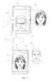
- FIG. 1is a schematic diagram illustrating a front view of a source telecommunication device 110 , and a destination telecommunication device 140 comprising a single camera 144 of a telecommunication system.
- the source telecommunication device 110includes a single camera 114 and a display device 112 that is observed by a source observer 100 .
- the destination telecommunication device 140includes a single camera 144 and a display device 142 observed by a destination observer 104 .
- the source observer 100 and the destination observer 104are shown in a reversed orientation here and in other drawings.
- the source telecommunication device 110 and the destination telecommunication device 140are capable of communication over a telecommunication network 199 . Images are transmitted over the telecommunication network 199 as follows in a teleconferencing method.
- the source telecommunication device 110transmits delivery images 120 captured by its camera 114 to the destination telecommunication device 140 which displays the delivery images 120 on its display device 142 .
- the destination telecommunication device 140transmits return images 108 captured by its camera 144 to the source telecommunication device 110 which displays the return images 108 on its display device 112 .
- the monoscopic (single lens) camera 114is positioned above the display device 112 .
- a point of interest 116 on a return image 108 displayed on the display device 112is observed by left eye 101 and right eye 102 of the source observer 100 .
- the point of interest 116may be located on a return image 108 comprising the face of the destination observer 104 , for example being typically the location between the eyes 105 , 107 of the destination observer 104 .
- the point of interest 116may be displaced by a vertical distance 113 from the camera 114 .
- Light rays from the point of interest 116 on the display device 118 to the eyes 101 , 102 of the source observer 100thus have a substantially different directionality to light rays 119 from the eyes 101 , 102 to the camera 114 .
- Destination telecommunications device 140includes a display device 142 and a camera 144 .
- the delivery image 120 of the source observer 100 captured by the camera 114 of the source device 110is displayed on the destination display device 142 with point of interest 117 that may be between the eyes 121 , 122 of the source observer 100 in the delivery image 120 .
- the destination observer 104 with left and right eyes 105 , 107respectively may observe the point of interest 117 and would desirably receive a source image that appears to be looking into the eyes of the destination observer.
- the source observer 100because of the difference in direction of rays 118 , 119 at the source telecommunications device 110 , the source observer 100 , as observed by the destination observer 104 observing the delivery image 120 , appears to be looking below the direction of the destination observer's line 123 of gaze to the point of interest 122 .
- the human visual systemhas evolved high sensitivity to the cues gained from the relative position of the iris and white sclera of other observers during social interaction. Small errors in the perceived gaze direction can create unnatural interactions.
- the perceived effect of the source observer 100 appearing to have a downwards gazeis highly disconcerting to the destination observer 104 and impacts on the ability of the source observer 100 and destination observer 104 to communicate with each other, thereby reducing the efficacy of the telecommunication system in providing teleconferencing. It would be desirable to achieve corrected gaze for observers connected by means of telecommunication devices.
- FIG. 2is a schematic diagram illustrating a front view of a source telecommunication device 150 and a destination telecommunication device 160 of a telecommunication system.
- the source display device 150includes a stereoscopic pair of cameras 154 , 156 and autostereoscopic display device 152 that is observed by a source observer 100 .
- the destination telecommunication device 160includes a stereoscopic pair of cameras 164 , 166 and an autostereoscopic display device 162 observed by a destination observer 104 .
- the autostereoscopic display devices 152 and 162are capable of displaying stereo images autostereoscopically, so that the source observer 100 and destination observer 104 perceive the stereo images with a stereoscopic effect.
- the source telecommunication device 150 and the destination telecommunication device 160are capable of communication over a telecommunication network 199 .
- imagesare transmitted over the telecommunication network 199 as follows in a teleconferencing method.
- the source telecommunication device 150transmits stereo delivery images 120 captured by its stereoscopic pair of cameras 154 , 156 to the destination telecommunication device 160 which displays the delivery images 120 on its display device 162 .
- the destination telecommunication device 160transmits stereo return images 108 captured by its stereoscopic pair of cameras 164 , 166 to the source telecommunication device 150 which displays the return images 108 on its display device 152 .
- the stereoscopic pair of cameras 154 , 156are positioned outside opposed sides of the display device 152 , being the vertical sides in FIG. 2 , at the same level partway along those sides.
- the cameras 154 , 156 of the source telecommunications device 150may respectively capture a right image 124 with right eye iris and sclera structures 125 , 126 , and a left image 128 with left eye iris and sclera structures 129 , 130 , the right and left images 124 , 128 being stereo images.
- the source observer 100appears to the destination observer 104 to have a gaze downwards. That perceived effect is reduced because the stereoscopic pair of cameras 154 , 156 are positioned outside opposed sides of the display device 152 , and so the cameras 154 , 156 are generally closer vertically to the point of interest 116 than in the case of FIG. 1 , but in general the point of interest 116 may not be at the level of the cameras 154 , 156 especially as source telecommunication device 150 moves with respect to the source observer 100 .
- the stereo delivery image 120may comprise left and right eye delivery images 137 , 138 , corresponding to the left and right images 124 and 126 respectively, that are displayed on the display device 162 autosterescopically.
- the destination observer 104observes a point of interest 117 on the display device 162 that is typically located between the eyes of the source observer 100 in the delivery image 120 . Considering the horizontal direction, the destination observer 104 looking at the point of interest 117 along ray 127 will perceive a three dimensional image that is analogous to the real world social interaction, that is a stereoscopic image of the sclera and irises for each eye, in particular with respect to the structure of the remainder of the face.
- the human visual systemhas evolved to provide high discrimination of gaze direction for stereo imagery and thus gaze cues are achieved, providing a highly natural interaction medium.
- the destination observer 104perceives that the source observer 100 has a gaze directed in his own horizontal direction (this does not consider the vertical effect on gaze discussed above).
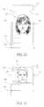
- FIG. 3illustrates the case that the destination device displays the delivery image in 2D and is a schematic diagram illustrating a front view of a source telecommunication device 150 of the type shown in FIG. 2 and a destination telecommunication device 140 of the type shown in FIG. 1 .
- the display device 142 of the destination telecommunication device 140is not capable of displaying the stereo delivery image 120 autostereoscopically and so displays the delivery image 120 in 2D, typically by displaying one image 138 of the stereo delivery image 120 .
- the perceived effect described above with reference to FIGS. 1 and 2 that the source observer 100 appears to the destination observer 104 to have a gaze downwardsbecause the point of interest 116 that is on the eye-line of the destination observer 104 in the return image 108 may be positioned at a vertical height 171 below the camera line 170 .
- the source observer 104 of return image 120will thus appear not to be looking at the camera line 170 .
- the delivery image 142will thus be perceived by the destination observer 104 to have a gaze below their own eye line, achieving an unnatural social interaction.
- each of the left and right images 124 , 128 considered individuallymay, when viewed on the display device 162 , appear to have a gaze in different directions.
- the image 138 of the stereo delivery image 120 that is displayed on the display device 142appears to the destination observer 104 to have a gaze that is directed sideways.
- This horizontal perceived effect on gazecauses similar issues to those caused by the vertical perceived effect on gaze described above resulting from the high sensitivity of the human visual system to the cues gained from the relative position of the iris and white sclera of other observers during social interaction.
- FIGS. 4 and 5illustrate a telecommunication system of the type described with reference to FIG. 2 but in which there is implemented a teleconferencing method that reduces the perceived effect described above that the source observer 100 appears to the destination observer 100 to be looking down.
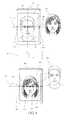
- FIG. 4is a schematic diagram illustrating a front view of the source telecommunication device 150 and the destination telecommunication device 150 of the telecommunications system.
- FIG. 5is a schematic diagram of the implemented method, illustrating processing performed on the return images 108 . This method is performed whilst the source telecommunication device 150 is transmitting stereo delivery images 120 captured by its stereoscopic pair of cameras 154 , 156 to the destination telecommunication device 160 .
- the stereoscopic pair of cameras 164 , 166 of the destination telecommunication device 160captures stereo return images 108 .
- Steps 200 and 201are performed in an image processing section 207 of the destination telecommunication device 160 , and steps 204 to 206 in an image processing section 210 of the source telecommunication device 150 .
- the image processing sections 207 and 210may be implemented by any suitable processing elements, for example a processor executing a suitable computer program or by dedicated hardware or by some combination of software and hardware.
- Steps 202 and 203are performed by a network interface 208 of the destination telecommunication device 160 and a network interface 209 of the source telecommunication device 150 , respectively.
- the network interfaces 208 and 209are interfaces with the telecommunication network 199 and may be provided by any elements suitable for implementing the communication protocol appropriate for the telecommunication network 199 .
- a faceis detected in the return image 108 .
- Thismay be performed using any suitable detection method, for example a feature detection method that detects features of a face such as eye features that identify parts of an eye and nose features that identify parts of the nose.
- the face detection step 200may provide the locations of a set of features in the return image 108 .
- the vertical level of the eye-line 173 of the detected faceis detected.
- the vertical level of the eye-line 173may be detected from the location of features detected in the face detection step 200 .
- the eye-line 173may be detected from detected eye features, in which case the eye-line 173 may be defined relative to those eye features.
- the eye-line 173may be detected in one or both of the stereo return images 108 .
- the center line 174 of the detected facebeing a vertical line extending through the notional center of the face.
- the horizontal position of the center line 174may be detected from the location of features detected in the face detection step 200 .
- the center line 174may be detected from detected eye features and/or nose features, in which case the center line 174 may be defined relative to those eye features.
- the center line 174may be detected in one or both of the stereo return images 108 .
- the stereo return images 108 , and associated data representing the detected the vertical level of the eye-line 173 , and if detected the horizontal position of the center line 174are transmitted by the destination telecommunication device 160 to the source telecommunication device 150 .
- a reception step 203 performed by the network interface 209the stereo return images 108 and the associated data are received by the source telecommunication device 150 from the destination telecommunication device 160 .
- a vertical offset step 204performed by the image processing section 210 , there is calculated the vertical offset 171 between the vertical level 170 of the cameras 154 , 156 along the sides of the display device 152 and the vertical level of the eye-line 173 when the stereo return images 108 are displayed on the display device 152 in a predetermined orientation (in FIG. 4 being a portrait orientation that is vertical), which is derived from the associated data transmitted from the destination telecommunication device 160 .
- an optional horizontal offset step 205performed by the image processing section 210 , there is calculated the horizontal offset between center of the display device 152 and the horizontal position of the center line 174 when the stereo return images 108 are displayed on the display device 152 in a predetermined orientation (in FIG. 4 being a portrait orientation that is vertical), which is derived from the associated data transmitted from the destination telecommunication device 160 .
- the stereo return image 108is shifted vertically by the vertical offset 171 calculated in the vertical offset step 204 and the horizontal offset calculated in the horizontal offset step 205 , if performed.
- the shifted return image 108is displayed on the display device 152 of the source telecommunication device 150 in the predetermined orientation.
- Steps 202 , 203 and 204together perform a vertical shift which positions the eye-line 173 of the detected face 108 at the level 170 of the stereoscopic cameras 164 , 166 upon display of the shifted return image 108 on the display device 152 of the source telecommunication device 150 in the predetermined orientation in which the vertical sides of the 108 image are substantially aligned with the opposed sides of the display device 152 .
- the perceived error in gaze directionmay be corrected and correct perceived gaze directions may be achieved for the return images 108 .
- Steps 202 , 203 and 205together perform a horizontal shift which positions the center line 173 of the detected face centrally upon display on the display device 152 of the source telecommunication device 150 in the predetermined orientation. This holds the face of the source user 100 in a constant position horizontally, even as the source device 150 moves relative to the source user 150 . This stabilizes the perceived return image 120 , increasing the efficacy of the telecommunication system in providing teleconferencing. Further, this may achieve correction of face disparity, so to arrange the observer's eyes at the screen plane, optimizing image performance at the most critical part of the face for natural social interaction.
- correction methodmay be performed in respect of the delivery images 120 communicated in the opposite direction, so that the destination images 120 are also correctly observed. Rays 131 and 133 on both source and destination devices may thus be aligned to achieve matched gaze cues for both source and destination observers 100 , 104 respectively.
- FIG. 3shows that the destination device may include a 2D display device and monoscopic camera, however preferably the destination device includes an autostereoscopic display device and stereoscopic camera as shown in FIG. 4 .
- the display device 152may have one pair of opposed sides that is longer than the other pair of opposed sides, said pair of stereoscopic cameras 154 , 156 of the source telecommunication device 150 being positioned outside the longer opposed sides of the display device 152 .
- the preferred eye line 173may typically be arranged above the center line 174 of the display so that advantageously some of the return image torso is visible.
- the pair of stereoscopic cameras 154 , 156 of the source telecommunication device 150may be positioned at the same level less than half-way along the longer opposed sides below the side of the display device that is the upper side with respect to said predetermined orientation.
- FIGS. 6A-Bare schematic diagrams illustrating top views of an autostereoscopic display device 162 using observer tracking that may optionally be implemented in the destination telecommunication device 160 .
- FIG. 6Aillustrates the case of a first observer location. Eyes 105 , 107 of the destination observer 104 are located in viewing windows 600 , 602 that are located at a window plane 106 located at a nominal viewing distance 464 from the display device 162 . If an observer's eye is within a viewing window then a single image is seen across the whole of the autostereoscopic display device 162 . If the observer eyes move out of the viewing window, no autostereoscopic image or an incorrect image is seen.
- an observer tracking systemmay be arranged making use of at least one camera 164 of the destination telecommunication device 160 .
- the viewing windowsmay be adjusted in lateral position to correctly align the viewing windows 600 , 602 with the observer's eyes 105 , 107 respectively.
- FIG. 7Ais a schematic diagram illustrating an example of the collection of data representing detected features in the face detection step 200 from a return image 108 displayed on the display device 152 of the source telecommunication device 150 .
- a face detectormay typically provide feature points 180 representing the locations of features using known computer vision techniques such as Active Shape Models (ASM) or Active Appearance Models (AAM) and described in “Active shape models—their training and application”, T. F. Cootes et al., Computer Vision and Image Understanding, 61(1):38-59, January 1995 and “Active appearance models”, T. F.
- ASMActive Shape Models
- AAMActive Appearance Models
- Feature points 180may describe particular locations on a face such as the outline of eyes and noses; for the present embodiments, establishing the location of features on eyes is particularly desirable.
- the location of the position between the observer's eyesmay be used to determine the output direction of the viewing windows in correspondence to observer position.
- FIGS. 7B-7Care schematic diagrams illustrating vertical gaze correction of a return image 108 on a display device 152 of a source telecommunication device 150 .
- the locations of inner and outer edges of left eye 182 , 184 respectively and right eye 186 , 188 respectivelycan advantageously be used to provide the nominal pupil positions for tracked illumination of an observer in an autostereoscopic display device and may further be used to determine the position of the eye-line 173 of the source observer 100 within the delivery image 120 .
- the data on the location of the eye-line 173may thus advantageously be determined at low additional processor cost over that required for tracked autostereoscopic display device, and may be transmitted with the image data from the destination telecommunication device.
- detecting a face in the return images 108may include detecting features of a face including eye features, with the eye-line 173 of the detected face being defined relative to the detected eye features.
- the location of the eye-line 173can be used to provide vertical correction without further face detection being required as shown in FIG. 7C .
- feature pointsmay be located on a server in the telecommunication network 199 or on the source telecommunication device 150 as described further below.
- the return image 108may not include a lower region, for example showing the torso and/or chin, in which case a blanking area 214 may be inserted in the that region.
- FIGS. 8A-8Bare schematic diagrams illustrating horizontal gaze correction of a return image 108 on a display device 152 of a source telecommunication device 150 .
- Feature pointsmay also be used to provide horizontal gaze correction.
- Face detectorsmay be arranged to locate the eye positions for left and right images, and a lateral position correction applied to one of the images to set the eyes with zero disparity.
- the line 190 of the feature point 188may be offset by a distance 194 to the left of the line 192 of the feature point 188 for the right eye image.
- the methodmay therefore include shifting the return images 108 horizontally to position the center line of the detected face centrally upon display of the shifted return images on the display device of the source telecommunication device in the predetermined orientation.
- the quality of eye-to-eye contactcan be increased by reducing the appearance of cross talk and the depth can be scaled around the eye location, that may be substantially aligned to the Glabella.
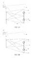
- FIGS. 9-11are schematic diagrams illustrating communication between source and destination telecommunication devices 150 and 160 arranged to achieve correction of the position of delivery and return images.
- FIGS. 9-11show examples in which the methods are applied bi-directionally to the return images 108 and the delivery images 120 , and the location in which the return images 108 and the delivery images 120 are processed is symmetrical.
- a stereoscopic pair of cameras 610 , a face detector 612 , an eye-line corrector 614 and an autostereoscopic display device 616 of source telecommunication device 150are arranged to cooperate with a stereoscopic pair of cameras camera 620 , a face detector 622 , an eye-line corrector 624 and an autostereoscopic display device 626 of destination telecommunication device 160 .
- the processing of return images 108is performed in the same devices as shown in FIG. 5 and described above.
- the face detectors 612 and 622may be arranged as part of the tracking system for the autostereoscopic display devices 616 and 626 , delivering detected face data 619 and 629 between the source device 150 and the destination device 160 .
- the steps of detecting facesis performed in the destination telecommunication device 160 and the step of shifting the return image is performed in the source telecommunication device 150 and vice versa for the delivery images 120 .
- a single face trackercan advantageously achieve detection for observer tracking and teleconferencing uses, reducing cost and power consumption in the destination device 160 and not significantly affecting the performance of the source device 150 .
- the face detectionmay be achieved by passing unprocessed return images 628 from the destination device 160 to the source device 150 delivery images 618 to the destination device 160 from the source device 150 , so that the detection and correction of face position is performed after transmission of the return images 628 and delivery images 618 .
- the steps of detecting faces and shifting the return images 628is performed in the source telecommunication device 150 and the steps of detecting faces and shifting the delivery images 628 is performed in the destination telecommunication device 160 .
- the destination telecommunication device 160may be able to run a more accurate and robust face detector than the source telecommunication device 150 , increasing performance for the system and enabling increased naturalness of interaction.
- FIG. 11the same components are present as in FIG. 9 , but the face detection and image correction of the return image is provided in the destination telecommunication device 160 and the face detection and image correction of the delivery image is provided in the source telecommunication device 150 , so that the corrected images 639 , 649 are communicated after the shifting.
- Knowledge of the position of the cameras in the source telecommunication device 150 and destination telecommunication device 160may be communicated by means of data 638 , 648 .
- such a processcan send images to devices in which the reliability of eye-line detection is low or no eye-line correction is incorporated in one of the source or destination devices.
- Such a processmay be further desirable for use in hybrid systems optimizing the performance by using mixtures of the methods in FIGS. 9-11 to reflect different processing capability of source and destination devices.
- FIGS. 12-13are further schematic diagrams illustrating communication between source and destination telecommunication devices 150 and 160 through a communications server 608 in the telecommunication network 199 arranged to achieve correction of the position of delivery and return images.
- the communications server 608may be located at a remote location to either or both the source and destination telecommunication devices 150 and 160 .
- the communications server 608is arranged to perform the face detection operations for delivery and return images in processing sections 650 , 652 implemented in the communications server 608 with data 654 , 656 transmitted to face detection modules determining camera line 170 location in source and destination devices respectively.
- the step of shifting the imagesmay be performed in eye-line correctors 624 , 614 of the source and destination telecommunication devices 150 and 160 as shown in FIG. 12 , or in the processing sections 650 , 652 of the communications server 608 as shown in FIG. 13 .
- data 658 , 660may be provided to the processing sections 650 , 652 respectively to determine display location with respect to stereo camera line 170 .
- the cost and complexity of the telecommunications devicesmay be reduced.
- FIG. 14is a schematic diagram illustrating the top view of the capture conditions of an observer 406 by a stereoscopic pair of cameras 154 , 156 of a source telecommunication device 1150 .
- the source telecommunication device 150includes the stereoscopic pair of cameras 154 , 156 with separation 450 of length A and an autostereoscopic display device 152 .
- the cameras 154 , 156are arranged to capture the stereo delivery images (which may comprise left and right images) of a source observer 406 located in front of a background 414 .
- the cameras 154 , 156have substantially the same lateral cone half-angle 454 of capture of size ⁇ .
- the capture half-angle 454is half the lateral angle of the field of view of the cameras 154 , 156 .
- the source observer 406may be arranged at a nominal distance 456 of length s from the autostereoscopic display device 152 , which may be for example the window plane 106 as described in FIG. 6A .
- Typical parameters for optical systems of autostereoscopic display devices and for relevant physiological characteristics of human observersare as follows.
- the optical system of autostereoscopic display devicesare designed, taking into account typical physiological characteristics of human observers, to achieve a window plane 106 at a distance 456 that is the most comfortable viewing distance for the majority of viewing population.
- the window plane of an autostereoscopic displayis the distance at which respective light sources of the autostereoscopic display are imaged for substantially all points across the width of the display.
- an observer with an eye in the image of a light sourcetermed the optical window, sees the same image across the whole width of the display.
- the light sourcesmay be formed from an array of pixels of a spatial light modulator in a spatially multiplexed display such as a lenticular or parallax barrier display; or may be individual light emitting elements in a temporally multiplexed display.
- the optical system of the autostereoscopic system(such as the lenticular screen, parallax barrier or optical valve) is arranged so that light sources are imaged from the center of the display in a first direction and light sources are imaged from points away from the center of the display in different controlled directions.
- the images from each point of the displayoverlap such that optical windows are formed at the intersection of said directions from points across the width of the display.
- the distance between the display and the optical windowsis the nominal viewing distance of the display.
- the window plane of mobile devices of display diagonal size in the range 3-10′′may be arranged at 300 mm for most adult observers, although may be 200-250 mm for children.
- the optimum viewing distancemay be increased to 400-700 mm. The window distance can thus be considered the optimum capture distance and replay distance of the respective display system.
- the region of interest for providing roundness of replayed imagesmay include but is not limited to the regions between the front of the nose and eyes, front of nose and ears or Glabella and rear of head.
- the distance 461may be defined as the distance of the plane 451 of the Glabella to the plane 453 of the back of the head and may be 20 cm for the 50 th percentile in men and 19 cm for the 50 th percentile in women. Ignoring small children, the bounds of distance may be considered approximately 17 cm to 22 cm.
- the distance 463 from the plane 451 of the Glabella to the plane 453 of the rearmost visible part of the headmay thus be considered to be approximately 10 cm and may be bounded by a few cm either side across the human population.
- the typical eye separation 460 of size E for the human populationmay be 62 mm, with a typical maximum of 68 mm for large adults and a typical minimum of 55 mm for small children.
- the angular field of viewmay be set to be +/ ⁇ 20°. This can achieve a width of view h of size h of +/ ⁇ 110 mm at a 300 mm nominal viewing distance. As display size varies it may be desirable to fix the angular field of view of the cameras 154 , 156 , or it may be desirable to fix the lateral width of view.
- FIG. 15is a schematic diagram illustrating the top view of the image replay conditions of the image 408 of the source observer 406 and the image 416 of the background 414 in an autostereoscopic display device of a destination device.
- a destination observer with left eye 460 and right eye 462 with separation 461 of size Emay be arranged at distance 464 that is nominally the same as distance 456 , being of length s.
- the destination observermay observe the destination autostereoscopic display device 162 with width 466 , perceiving the autostereoscopic image 408 of the source observer 406 and image 416 of the background 414 .
- both the source and destination telecommunication devices 150 and 160may be typically arranged to have substantially the same camera separation 450 of size A which is slightly larger than the display width, W.
- the camera separationmay be considered to be an oversize factor ⁇ that may be 5% so that the camera separation is 105° % of the display width.
- the oversize parameterarises from the finite width of the bezel of the optical system comprising the edges of the spatial light modulator of a display system and the width of the respective autostereoscopic optical components.
- the size A and width Ware similar with size A being slightly larger than width W.
- a display of diagonal 5′′ and aspect ratio 4:3 arranged in portrait orientationmay have a display aperture width W of 3′′.
- the bezel widthmay be 2 mm on each side and each camera may have a body width of 2 mm with a centrally aligned camera aperture in the camera body.
- the camera separationmay thus be 82 mm, and the oversize parameter, ⁇ may be 0.07.
- Either the size A or width Wmay be considered in the following discussion.
- FIG. 16is a graph of perceived stereoscopic depth against actual depth for a typical stereoscopic capture and display telecommunication system comprising uncorrected camera geometry and image background.
- the perceived stereoscopic depth 400is mapped against the actual depth 402 for the observer 406 and background 414 .
- the geometry of the capture of the delivery image at the source telecommunication device 150 and display at the destination telecommunication device 160may determine a transfer function 404 , such that the image 406 and background 414 may undergo some substantial distortion artifacts on display as images 408 and 416 .
- the plane 410 of the Glabella of the source observer 406is thus mapped to plane 412 while the plane of the tip of the observer's nose 411 is mapped to plane 413 .
- distance 417may be substantially greater than the distance 415 .
- Pinocchio effectmay arise to grow the perceived length of the observer's nose in an unnatural manner.
- Such artifactsare clearly visible in use as the human visual system has evolved high sensitivity to any unusual appearance of other human faces and are thus typically unacceptable in use.
- FIG. 17is a graph of perceived stereoscopic depth against actual depth for a stereoscopic capture and display telecommunications system arranged to achieve perceived head roundness and corrected image background.
- the geometry of the capture of the delivery image at the source device and replay at the destination devicemay arranged to achieve a transfer function 405 that is substantially linear in the region of the observer's head 406 , and thus the ratio of head width to length can be preserved, achieving roundness.
- the distance 415may be mapped to distance 419 that is in proportion to the size of the replayed observer's head 418 .
- the roundness of the observer's head on the destination devicecan be made substantially with correct roundness, scaled with the replayed observer's head size.
- a flat and linear transfer function 420may be arranged as will be described below, so that background objects are mapped to a single 2D plane.
- the desired camera separation 450 of size A to achieve roundness of the image of the head on the destination display device 162may be given by
- Eis the eye separation 461 of the destination observer
- sis the viewing distance 464 of the destination observer
- ⁇is the depth 461 of the head of the source observer 460 as shown in FIG. 14
- ⁇is the lateral capture half-angle 454 of the cameras 154 , 156 of the source telecommunication device 150
- Wis the width 466 of the display device 162 .
- the width W and separation Amay be considered to be substantially the same for the source and destination telecommunication devices 150 and 160 .
- stereoscopic camerasthat are arranged to provide correct gaze may be set just outside the width 466 of the display device. Further the nominal viewing distance 464 for the display device 162 of the destination telecommunication device 160 is typically arranged to be the same length s as for the display device 152 of the source telecommunication device 150 .
- Setting AW *(1+ ⁇ ) eqn.2 and solving for W in eqn. 1, the relationship between display width W (and thus camera separation A) can be derived for a range of viewing distances, camera capture half-angles and typical human physiological properties.
- FIGS. 18-19are schematic graphs at different scales of the size A of the camera separation 450 against the length s of the viewing distance 464 for an autostereoscopic electronics device arranged to achieve perceived head roundness for a given size ⁇ of the capture half-angle 454 , in this case of 20° which is a typical value.
- Specific values of the relevant parameters of the size E of the eye separation 461 of the destination observer and the size ⁇ of the depth 461 of the head of the source observer 406spread across the typical ranges for those parameters in the human population as discussed above, are selected and the respective curves for those specific values are plotted.
- the size A of the camera separation 450 in FIG. 18is varied in the range up to approximately 17′′ display diagonal, while the range of viewing distances is adjusted between typical maximum and minimum values for such range of display sizes.
- the size ⁇ of the capture half-angle 454is set as 20° and the camera separation to display width oversize factor ⁇ is set to a typical value of 5%.
- Curves 480 , 482 , 484 , 486 , 488are arranged with different settings of observer eye spacing E in the range 55-58 mm and preferred compensation region depth ⁇ in the range 80-220 mm.
- the curvestherefore illustrate how the size A of the camera separation 450 that achieves perceived head roundness varies with the length s of the viewing distance 464 .
- the curvesare surprisingly tightly grouped for across the typical range of parameters in the human population and across a wide range of values of the distance s of the nominal viewing distance 464 for the display device 162 .
- a round faceis achieved for size A of the camera separation 450 of approximately 83 mm, corresponding to a display width W 466 of 79 mm.
- the other curvesshow close grouping around that the size A of the camera separation 450 .
- all the curvesshow the size A of the separation 450 of the cameras 154 , 156 in the stereoscopic display device in a range f with a lower limit of 60 mm and an upper limit of 95 mm.
- the separation 450 of the camerasis only slightly larger.
- FIGS. 20A-20Bare graphs at different scales of the size A of the camera separation 450 against the length s of the viewing distance 464 for an autostereoscopic telecommunications system arranged to achieve perceived head roundness for a given size h of the width of view so that the size ⁇ of the camera half-angle 454 varies with the length s of the nominal viewing distance 464 .
- specific values of the relevant parameters of the size E of the eye separation 461 of the destination observer and the size ⁇ of the depth 461 of the head of the source observer 406spread across the typical ranges for those parameters in the human population as discussed above, are selected and the respective curves for those specific values are plotted.
- the curvestherefore again illustrate how the size A of the camera separation 450 that achieves perceived head roundness varies with the length s of the viewing distance 464 .
- the range of useful sizes A of the camera separations 450remains surprisingly small and similar to the arrangement of FIGS. 18-19 .
- all the curvesshow the size A of the separation 450 of the cameras 154 , 156 in the stereoscopic display device in a range 491 with a lower limit of 65 mm and an upper limit of 95 mm, with a slight increase in the separation 450 of the cameras at other values of the viewing distance 464 .
- FIG. 21Ais a graph of the size A of the camera separation 450 against size ⁇ of the capture half-angle 454 for an autostereoscopic telecommunications system arranged to achieve perceived head roundness, for a given size ⁇ of the depth 461 of the head of the source observer 406 , in this case of 190 mm which is a typical value.
- Specific values of the relevant parameters of the size E of the eye separation 461 of the destination observer and the length s of the viewing distance 464 , spread across the typical ranges for those parameters in the human population as discussed above,are selected and the respective curves for those specific values are plotted.
- the curvestherefore illustrate how the size A of the camera separation 450 that achieves perceived head roundness varies with the size ⁇ of the capture half-angle 454 .
- the curvesare surprisingly tightly grouped for across the typical range of parameters in the human population and across a wide range of values of the size ⁇ of the capture half-angle 454 .
- the curvesshow similar values of the size A of the camera separation 450 , although there is slightly wider variation than with the distance s of the nominal viewing distance 464 for the display device 162 .
- the curves 502 , 504 , 506 , 508 , 510 , 512show the size A of the separation 450 of the cameras 154 , 156 in the stereoscopic display device in: a range 516 with a lower limit of 70 mm and an upper limit of 90 mm for a capture half-angle 454 of size ⁇ of 20°, a range 518 with a lower limit of 60 mm and an upper limit of 85 mm for a capture half-angle 454 of size ⁇ of 10°, a range 520 with a lower limit of 70 mm and an upper limit of 110 mm for a capture half-angle 454 of size ⁇ of 50°, and an overall range 522 with a lower limit of 60 mm and an upper limit of 110 mm.
- FIG. 21Bis a graph of the same quantities as FIG. 21A but plotting additional curves for varying values of the size ⁇ of the depth 461 of the head of the source observer 406 .
- the curvesshow similar values of the size A of the camera separation 450 to FIG. 21A .
- the curves 530 , 532 , 534 , 536 , 538 , 540show the size A of the separation 450 of the cameras 154 , 156 in the stereoscopic display device in: a range 542 with a lower limit of 60 mm and an upper limit of 95 mm for a capture half-angle 454 of size ⁇ of 20°, in a range 544 with a lower limit of 60 mm and an upper limit of 80 mm for a capture half-angle 454 of size ⁇ of 10°, 546 with a lower limit of 75 mm and an upper limit of 110 mm for a capture half-angle 454 of size ⁇ of 50°, and 522 with a lower limit of 60 mm and an upper limit of 110 mm.
- FIGS. 21A-Bsuggest slightly larger ranges of optimum display width to preserve head roundness given a larger range of field angles.
- the separation 450 between the centers of the cameras 154 , 156may have a size A in a range having a lower limit of 60 mm and an upper limit of 110 mm. More preferably the lower limit may be 65 mm or 70 mm. More preferably, the upper limit may be 100 mm or 90 mm.
- Such values of the separation 450are particularly suitable for typical values of the lateral capture half-angle that of at most 50° or more preferably at most 30°. Such values of the separation 450 are particularly suitable for typical values of the lateral capture half-angle that of at least 10°. Such values of the separation 450 are particularly suitable for typical values of the distance 464 of the window plane from the display device 162 of at least 200 mm. Such values of the separation 450 are particularly suitable for typical values of the distance 464 of the window plane from the display device 162 of at most 400 mm.
- Such parametersmay be applied to any of the telecommunication devices disclosed herein, or more generally to any other electronic device that includes a display device that is capable of displaying stereo images autostereoscopically and a pair of stereoscopic cameras positioned outside opposed sides of the display device at the same level partway along those sides.
- FIGS. 22-23are schematic diagrams illustrating front views of the display devices 162 and 152 of destination and source telecommunication devices 160 and 150 for an autostereoscopic telecommunications system arranged to achieve perceived head roundness.
- a destination telecommunication device 160 device as shown in FIG. 22may be arranged in portrait mode with a lateral display width of 79 mm, that is with the pair of stereoscopic cameras 164 , 146 positioned outside the longer opposed sides of the display device 162 .
- Such a display devicecan be achieved by a 4:3 aspect ratio panel boundary 672 of diagonal size 5.2′′ or a 16:9 aspect ratio panel boundary 670 of diagonal size 6.3′′.
- the display device 152may in another illustrative embodiment be arranged in landscape mode with a lateral display width W of 79 mm, that is with the pair of stereoscopic cameras 154 , 156 positioned outside the shorter opposed sides of the display device 162 .
- Such a display device 152can be achieved by a 4:3 aspect ratio panel boundary 671 of diagonal size 3.9′′ or a 16:9 aspect ratio panel boundary 673 of diagonal size 3.6′′.
- the camera separation 450 of the source telecommunication device 150may be desirably arranged at a size A such that the background object 414 may be displayed on the destination telecommunication device 160 with disparity between left and right images that may be outside ranges that can achieve comfortable levels of convergence for observers. Such disparities may result in excessive visual strain.
- the desired results of roundness of head shape and background images without excessive disparitycannot be achieved by the same capture geometry in typical use for telecommunication devices.
- mapping function 420in which the image 416 of the background 414 has a degree of perceived stereoscopic depth that is compressed to an image with no depth or limited depth, so that background 414 is directed to width 423 with little or no perceived depth.
- This methodmay be implemented in a telecommunication system as described above with reference to FIG. 2 in which the source telecommunication device 150 includes a stereoscopic pair of cameras 154 , 156 and the destination telecommunication device 160 includes an autostereoscopic display device 162 that is capable of displaying stereo images autostereoscopically.
- FIGS. 24A-24Gare schematic diagrams each illustrating a pair of left and right images of a stereo delivery image as they are processed by the method to apply image corrections to correct the background stereoscopic depth for an autostereoscopic telecommunications system further arranged to achieve perceived head roundness.
- FIG. 25is a flow chart of the method itself.
- Steps 700 to 718 of the methodare image processing steps that may be performed in one or more image processing section of one or more components of the telecommunication system.
- Possible componentsinclude the source telecommunication device 150 , the destination telecommunication device 160 or a server in the telecommunication network 199 through which the delivery images are transmitted.
- the image processing sectionsmay be implemented by any suitable processing elements, for example a processor executing a suitable computer program or by dedicated hardware or by some combination of software and hardware.
- FIG. 24Ashows an example of the left image 300 and the right image 302 of a stereo delivery image of a head and optionally a torso of observer 100 captured by the stereoscopic pair of cameras 154 , 156 of the source telecommunication device 150 .
- the disparity 314 between the left and right eye images 300 , 302may be substantially different from the disparity 312 of the background, such that the background disparity 312 may be excessive.
- the imagehas an outer border 308 and may also have an inner border 310 described further below.
- input steps 700 and 710the left and right images captured by the cameras 154 , 156 are input.
- eye-line correction steps 702 and 712that are optional when the method of FIG. 25 is performed, the left and right images are processed to provide eye-line correction using the method described above with reference to FIG. 4 .
- the left and right imagesare segmented to identify the regions of the head and if present torso (hereinafter referred to as the “foreground” for brevity) of the images.
- the foregroundmay comprise the whole head and torso or parts thereof, for example the face only in which embodiment, the background may comprise for example hair and torso regions.
- FIG. 24Bshows a segmentation of the foreground from the backgrounds to identify the foregrounds 320 , 322 of the left and right images (the segmentation region 322 of the right image being shown in dotted outline on the left image for comparison).
- FIG. 24Bshows a segmentation of the foreground from the backgrounds to identify the foregrounds 320 , 322 of the left and right images (the segmentation region 322 of the right image being shown in dotted outline on the left image for comparison).
- FIG. 24Bshows a segmentation of the foreground from the backgrounds to identify the foregrounds 320 , 322 of the left and right images (the segmentation
- FIG. 24Cshows the background images after the foreground is removed, indicating the boundaries of segmentation regions 320 , 322 respectively and providing segmented backgrounds 324 , 326 .
- FIG. 24Dshows the segmented foreground background regions 330 , 332 replaced by null image regions.
- Segmentation steps 704 and 714may use any suitable segmentation technique of the known and varied types in the field of computer vision, for example using active and/or passive segmentation technologies.
- segmentation techniqueFor use in teleconferencing, there may be used any segmentation technique that can process video images in real time, depending on the image size and frame rate, which may depend on the bandwidth available in the telecommunication network 199 for transmission of the stereo delivery images.
- the segmentation techniquemay be chosen to achieve a desired balance between the available processing resource and the quality of the segmentation.
- the next steps togetherreplace the segmented background of the left and right images by replacement images having a degree of perceived stereoscopic depth that is lower than the degree of perceived stereoscopic depth within the original images.
- the replacement images for both of the left and right imagescomprises a common image so that the replacement images provide a planar stereo image having no perceived stereoscopic depth within them. This effectively provides the background with the function 420 shown in FIG. 17 .
- the replacement imagesare derived from one of the segmented backgrounds 324 , 326 (in this example the background 324 of the left image but the background 326 of the right image could similarly be used).
- the new backgroundis derived as follows.
- the segmented background 324 of the left imageis selected, and in demagnification step 722 the segmented background 324 is demagnified. Then, in disparity steps 724 and 726 , the demagnified, segmented background 324 output by the demagnification step 722 is shifted horizontally in opposite direction to generate two versions of the demagnified, segmented background 324 with horizontal disparity, which are used as the left and right replacements images 325 , 327 .
- FIG. 24Eshows the step of deriving the left and right replacement images 325 , 327 derived from the demagnified, segmented background 324 shown in FIG. 24C . Due to the demagnification, the outer boundary 308 of the original left image 300 is shrunk to the size of the inner boundary 310 , reducing the size of the replacement images 325 , 327 . This ensures that the boundary 336 of the replacement images 325 , 327 around the foreground shrinks to the extent that it is entirely inside the region of the segmented foregrounds 320 , 322 of both the left and right images. This prevents there being a blank region when the segmented foreground 320 of the right image is superimposed on the left replacement images 325 as described below.
- the segmented backgrounds in the left and right imagesare replaced by the left and right replacements images 325 and 327 as follows.
- selection steps 706 , 716the segmented foregrounds 320 , 322 of the left and right images are selected and in steps 708 , 718 , segmented foregrounds 320 , 322 of the left and right images are superimposed on the left and right replacements images 325 , 327 derived in steps 724 , 726 .
- FIG. 24Fshows the resultant left and right images.
- the edge region between borders 308 , 310may be removed from the resultant images.
- the replacement images 325 , 327comprise a common image, that is the demagnified, segmented image 324 , with a horizontal disparity 336
- the replacement images 325 , 327have a perceived stereoscopic depth behind the foreground to achieve the appropriate disparity for the background.
- the background disparity 336may be set so that the background is set at the rear of the observer's ears, at the back of their head, or preferably behind the back of their head to avoid conflict with depth cues in the stereoscopic reproduction of the head.
- a region 334may be present that has no image information. Such an effect can be reduced by increasing the lateral field of capture of the stereoscopic cameras 154 , 156 to capture excess information.
- the stereo delivery imagecomprising the left and right images having the replaced, segmented backgrounds generated in steps 708 , 718 are displayed autostereoscopically on the display device 162 of the destination telecommunication device 160 .
- FIG. 24Gshows the displayed stereo delivery image including a segmented foreground region 340 comprising a range of disparity information to achieve face roundness and a background region 342 comprising planar background information with a disparity that is set behind the observer's head but has lower disparity 336 than the disparity 312 of the source background images.
- the segmented backgroundsare replaced by respective replacement images that have a degree of perceived stereoscopic depth within the replacement images that is lower than degree of perceived stereoscopic depth within the original backgrounds.
- a stereoscopic teleconferencing systemcan achieve correct gaze characteristics, correct face roundness characteristics and a background image with high levels of visual comfort arising from lower levels of background disparity than would be achieved from the raw background images.
- the replacement images 325 , 327are derived from one of the segmented backgrounds 324 , 326 , the viewer still perceives the actual background that is behind the observer 100 captured by the stereoscopic pair of cameras 154 , 156 of the source telecommunication device 150 . This produces a very natural effect.
- the replacement images 325 , 327are derived from one of the left and right eye images 300 , 302
- the replacement images 325 , 327could be derived with a degree of stereoscopic depth that is lower than degree of perceived stereoscopic depth within the original backgrounds.
- that requires significant image processing to generate appropriate background imagesand in some cases might not even be practicable with the available processing power. Accordingly, deriving replacement images 325 , 327 that are a common image derived from one of the left and right eye images 300 , 302 may achieve a similar effect with greater ease and lower processing power.
- the replacement images 325 , 327need not be derived from the left and right eye images 300 , 302 , as for example in the following alternative methods.
- FIGS. 26A-26Dare schematic diagrams each illustrating a pair of left and right images of a stereo delivery image as they are processed by the method to apply image corrections to correct the background stereoscopic depth for an autostereoscopic telecommunications system further arranged to achieve perceived head roundness.
- FIG. 27Ais a flow chart of the method itself.
- the alternative methodis the same as the method of FIG. 25 except for the following modification.
- the alternative methodis applied to a destination telecommunication device as illustrated in FIG. 27B having a rear monoscopic camera arrangement 168 facing in the opposite direction from the display device 162 , and from the stereoscopic pair of cameras 164 , 166 , that is facing in the same direction as the source observer towards the outside world.
- Lateral camera capture full angles 151 , 153may be different to capture angle 155 of camera 168 , with the former arranged to achieve teleconferencing preserving head roundness, while the latter is arranged to achieve suitable field of view for more general photography and videophotography uses.
- the alternative methoddiffers in that the left and right images replacement images 380 , 382 are derived from the image captured by the rear camera arrangement 168 , in particular comprising a common image captured by the rear camera, as shown in FIG. 26B .
- the image captured by the rear camera arrangement 168is input and this is used in steps 724 , 726 .
- FIGS. 26A, 26C and 26Dcorrespond to FIGS. 24D, 24F and 24G .
- the rear camera 168may be replaced by a stereoscopic pair of cameras 167 , 169 , in which case the background image may be a stereo image pair comprising left and right images 380 , 382 .
- the assembled stereoscopic image 384 shown in FIG. 26Dmay include a foreground with correct roundness properties and a background with acceptable levels of disparity.
- Lateral camera capture full angles 151 , 153may be different to capture angles 157 159 , with the former arranged to achieve teleconferencing preserving head roundness, while the latter arranged to achieve suitable field of view for more general stereophotography; said cameras 167 , 169 may thus be arranged with fields of view and separation in a manner that would provide head distortion if they were to be used in a teleconferencing application.
- FIG. 28is a flow chart of the method in this case, wherein in input step 732 the left and right images captured by the rear camera arrangement 168 are input and are used in steps 708 and 718 as the left and right replacement images. Otherwise the method remains the same as described above, except that the eye-line correction steps 702 , 712 are performed after replacement of the background (which is also a possible modification to the methods of FIGS. 25 and 27A ).
- the use of the rear camera arrangement 168 in telecommunication useachieves control by the user of what is seen by the observer of the destination image in the background. This avoids the uncertainty of not being able to see what is behind you in social interactions and increases the level of perceived control of the interface.
- the replacement imagesare derived from images captured by a camera of the source telecommunication device 150 .
- the replacement imagescould be derived separately, for example being images that are stored or images that generated during the communication from the source telecommunication device 150 to the destination telecommunication device 160 .
- the image processing performed in stepsmay be performed in any device or any combination of devices of the telecommunication system through which the delivery images pass, including without limitation the source telecommunication device 150 , the destination telecommunication device 160 or a server in the telecommunication network 199 through which the images are transmitted. Some non-limitative examples of this are shown in FIGS. 29-31 are schematic diagrams illustrating communication between source and destination devices 150 and 160 arranged to achieve correction of the background of delivery and return images.
- FIGS. 29-31show examples in which the methods are applied bi-directionally to the return images 108 and the delivery images 120 , and the location in which the return images 108 and the delivery images 120 are processed is symmetrical.
- stereo delivery images captured by a stereoscopic pair of cameras 610 of the source telecommunication device 150are displayed autosterescopically on a display device 746 of the destination telecommunication device 160
- stereo return images captured by a stereoscopic pair of cameras 620 of the destination telecommunication device 160are displayed autosterescopically on a display device 742 of the source telecommunication device 150 .
- the background replacement methodis performed on the delivery images by an image processing section 740 of the source telecommunication device 150
- the background replacement methodis performed on the return images by an image processing section 744 of the destination telecommunication device 160 , following which image 748 , 749 having the replaced backgrounds is sent to the 3D display devices 746 , 742 of the other of the destination and source telecommunication devices 160 and 150 .
- the sendercan choose the replacement image content.
- the background replacement methodis performed on the delivery images by an image processing section 744 of the destination telecommunication device 160
- the background replacement methodis performed on the return images by an image processing section 740 of the source telecommunication device 150 so that unprocessed stereo images 750 , 752 are transferred and the processing occurs on the respective destination and source devices 160 , 150 respectively.
- the replacement imagealso needs to be transmitted, or alternatively an image from a camera where the processing is performed may be used in which case advantageously the recipient of the image can choose the replacement image content.
- the background replacement methodis performed on the delivery images by an image processing section 748 of a server 608 in the telecommunication network 199 through which the images are transmitted, and the background replacement method is performed on the return images by an image processing section 748 of a server 608 in the telecommunication network 199 through which the images are transmitted.
- unprocessed imagesare transmitted to the server 608 which transmits on images with replaced the backgrounds.
- Data 741 , 743may be passed from the destination and source devices 160 , 150 respectively to the server 608 to determine the requirement of disparity of background data in the replacement images.
- a choice between sender, recipient, or a third party, such as a sponsoring advertisermay determine the nature of the replacement image content. Further the requirement for local processing of image data can be reduced, reducing cost and complexity of source and destination devices.
- the autostereoscopic display devices 152 and 162may be any type of display device that is capable of displaying stereo images without additional equipment worn by the observer.
- Non-limitative examples of types of display device that are suitable for the autostereoscopic display of the present embodimentsinclude but are not limited to wedge display devices, lenticular display devices, parallax barrier display devices, beam splitter display devices and light line display devices.
- the autostereoscopic display devicecould be replaced by a stereoscopic display device.
- Stereoscopic display devicesmay include but are not limited to micropolarizer display devices, film patterned retarder display devices or shutter glasses display devices.
- Stereoscopic display devicesrely on head-mounted equipment such as a pair of glasses to provide the stereoscopic effect, so the visibility of the relative iris and sclera positions of observer eyes may be compromised.
- the autostereoscopic display devices 152 and 162may be time multiplexed, that is providing the left and right images to the left and right eyes in a time multiplexed manner.
- Time multiplexed autostereoscopic display devicescan advantageously improve the spatial resolution of autostereoscopic display device by directing light from all of the pixels of a spatial light modulator to a first viewing window in a first time slot, and all of the pixels to a second viewing window in a second time slot.
- an observer with eyes arranged to receive light in first and second viewing windowswill see a full resolution image across the whole of the display device over multiple time slots.
- Time multiplexed display devicescan advantageously achieve directional illumination by directing an illuminator array through a substantially transparent time multiplexed spatial light modulator using directional optical elements, wherein the directional optical elements substantially form an image of the illuminator array in the window plane.
- FIG. 32is a schematic diagram illustrating the structure of one type of an autostereoscopic display device for an autostereoscopic telecommunications system, as described in U.S. patent application Ser. No. 13/300,293.
- a stepped waveguide 1(also referred to as an optical valve) is arranged to direct light from an array 15 of light sources to left viewing window 44 and right viewing window 26 .
- the light sourcesmay be adjusted to move the viewing windows, achieving autostereoscopic imaging for observer 45 .
- the viewing windowsare arranged at a nominal distance from the display device by means of the imaging properties of the stepped waveguide 1 . Such nominal viewing distance determines the best viewing position for an observer.
- FIG. 33is a schematic diagram illustrating a control system for an autostereoscopic display device for an autostereoscopic telecommunications system.
- the arrangement and operation of the control systemwill now be described and may be applied to an autostereoscopic display device of the type disclosed in U.S. patent application Ser. No. 13/300,293.
- a directional display device 100may include a directional backlight device that may itself include a stepped waveguide 1 and a light source illuminator array 15 .
- the stepped waveguide 1includes a light directing side 8 , a reflective end 4 , guiding features 10 and light extraction features 12 .
- the directional display device 100may further include an SLM 48 .
- the waveguide 1is arranged as described above.
- the reflective end 4converges the reflected light.
- a Fresnel lens 62may be arranged to cooperate with reflective end 4 to achieve viewing windows 26 at a viewing plane 106 observed by an observer 99 .
- a transmissive SLM 48may be arranged to receive the light from the directional backlight. Further a diffuser 68 may be provided to substantially remove Moiré beating between the waveguide 1 and pixels of the SLM 48 as well as the Fresnel lens structure 62 .
- the control systemmay include a sensor system arranged to detect the position of the observer 99 relative to the display device 100 .
- the sensor systemincludes a position sensor 70 , such as a camera, and a head position measurement system 72 that may for example be a computer vision image processing system.
- the control systemmay further include an illumination controller 74 and an image controller 76 that are both supplied with the detected position of the observer supplied from the head position measurement system 72 .
- the illumination controller 74selectively operates the illuminator elements 15 to direct light to into the viewing windows 26 in cooperation with waveguide 1 .
- the illumination controller 74selects the illuminator elements 15 to be operated in dependence on the position of the observer detected by the head position measurement system 72 , so that the viewing windows 26 into which light is directed are in positions corresponding to the left and right eyes of the observer 99 . In this manner, the lateral output directionality of the waveguide 1 corresponds with the observer position.
- the image controller 76controls the SLM 48 to display images.
- the image controller 76 and the illumination controller 74may operate as follows.
- the image controller 76controls the SLM 48 to display temporally multiplexed left and right eye images.
- the illumination controller 74operate the light sources 15 to direct light into respective viewing windows in positions corresponding to the left and right eyes of an observer synchronously with the display of left and right eye images. In this manner, an autostereoscopic effect is achieved using a time division multiplexing technique.
- the terms “substantially” and “approximately”provide an industry-accepted tolerance for its corresponding term and/or relativity between items. Such an industry-accepted tolerance ranges from zero percent to ten percent and corresponds to, but is not limited to, component values, angles, et cetera. Such relativity between items ranges between approximately zero percent to ten percent.
Landscapes
- Engineering & Computer Science (AREA)
- Multimedia (AREA)
- Signal Processing (AREA)
- Computer Vision & Pattern Recognition (AREA)
- Physics & Mathematics (AREA)
- General Physics & Mathematics (AREA)
- Theoretical Computer Science (AREA)
- Testing, Inspecting, Measuring Of Stereoscopic Televisions And Televisions (AREA)
- Two-Way Televisions, Distribution Of Moving Picture Or The Like (AREA)
- Controls And Circuits For Display Device (AREA)
Abstract
Description
A=W*(1+δ) eqn.2
and solving for W in eqn. 1, the relationship between display width W (and thus camera separation A) can be derived for a range of viewing distances, camera capture half-angles and typical human physiological properties.
Claims (16)
Priority Applications (1)
| Application Number | Priority Date | Filing Date | Title |
|---|---|---|---|
| US15/199,106US9872007B2 (en) | 2013-06-17 | 2016-06-30 | Controlling light sources of a directional backlight |
Applications Claiming Priority (3)
| Application Number | Priority Date | Filing Date | Title |
|---|---|---|---|
| US201361835923P | 2013-06-17 | 2013-06-17 | |
| US14/306,690US9407868B2 (en) | 2013-06-17 | 2014-06-17 | Controlling light sources of a directional backlight |
| US15/199,106US9872007B2 (en) | 2013-06-17 | 2016-06-30 | Controlling light sources of a directional backlight |
Related Parent Applications (1)
| Application Number | Title | Priority Date | Filing Date |
|---|---|---|---|
| US14/306,690DivisionUS9407868B2 (en) | 2013-06-17 | 2014-06-17 | Controlling light sources of a directional backlight |
Publications (2)
| Publication Number | Publication Date |
|---|---|
| US20160316188A1 US20160316188A1 (en) | 2016-10-27 |
| US9872007B2true US9872007B2 (en) | 2018-01-16 |
Family
ID=52018878
Family Applications (2)
| Application Number | Title | Priority Date | Filing Date |
|---|---|---|---|
| US14/306,690ActiveUS9407868B2 (en) | 2013-06-17 | 2014-06-17 | Controlling light sources of a directional backlight |
| US15/199,106Active2034-06-25US9872007B2 (en) | 2013-06-17 | 2016-06-30 | Controlling light sources of a directional backlight |
Family Applications Before (1)
| Application Number | Title | Priority Date | Filing Date |
|---|---|---|---|
| US14/306,690ActiveUS9407868B2 (en) | 2013-06-17 | 2014-06-17 | Controlling light sources of a directional backlight |
Country Status (6)
| Country | Link |
|---|---|
| US (2) | US9407868B2 (en) |
| EP (1) | EP3011734A4 (en) |
| JP (1) | JP2016529764A (en) |
| KR (1) | KR102254799B1 (en) |
| CN (2) | CN110234000B (en) |
| WO (1) | WO2014204950A1 (en) |
Cited By (5)
| Publication number | Priority date | Publication date | Assignee | Title |
|---|---|---|---|---|
| US10321123B2 (en)* | 2016-01-05 | 2019-06-11 | Reald Spark, Llc | Gaze correction of multi-view images |
| US10634840B2 (en)* | 2015-04-13 | 2020-04-28 | Reald Spark, Llc | Wide angle imaging directional backlights |
| US10740985B2 (en) | 2017-08-08 | 2020-08-11 | Reald Spark, Llc | Adjusting a digital representation of a head region |
| US10891478B2 (en) | 2015-03-20 | 2021-01-12 | Skolkovo Institute Of Science And Technology | Method for correction of the eyes image using machine learning and method for machine learning |
| US11017575B2 (en) | 2018-02-26 | 2021-05-25 | Reald Spark, Llc | Method and system for generating data to provide an animated visual representation |
Families Citing this family (36)
| Publication number | Priority date | Publication date | Assignee | Title |
|---|---|---|---|---|
| US9678267B2 (en) | 2012-05-18 | 2017-06-13 | Reald Spark, Llc | Wide angle imaging directional backlights |
| EP2850488A4 (en) | 2012-05-18 | 2016-03-02 | Reald Inc | Directional backlight |
| KR102099590B1 (en) | 2012-05-18 | 2020-04-10 | 리얼디 스파크, 엘엘씨 | Controlling light sources of a directional backlight |
| US9188731B2 (en) | 2012-05-18 | 2015-11-17 | Reald Inc. | Directional backlight |
| KR101979669B1 (en)* | 2012-07-13 | 2019-05-17 | 삼성전자주식회사 | Method for correcting user’s gaze direction in image, machine-readable storage medium and communication terminal |
| CN111487707A (en) | 2013-02-22 | 2020-08-04 | 瑞尔D斯帕克有限责任公司 | directional backlight |
| EP3058562A4 (en) | 2013-10-14 | 2017-07-26 | RealD Spark, LLC | Control of directional display |
| KR102366346B1 (en) | 2013-10-14 | 2022-02-23 | 리얼디 스파크, 엘엘씨 | Light input for directional backlight |
| EP3161550A4 (en) | 2014-06-26 | 2018-04-18 | RealD Spark, LLC | Directional privacy display |
| WO2016057690A1 (en) | 2014-10-08 | 2016-04-14 | Reald Inc. | Directional backlight |
| US10356383B2 (en) | 2014-12-24 | 2019-07-16 | Reald Spark, Llc | Adjustment of perceived roundness in stereoscopic image of a head |
| CN104574321B (en)* | 2015-01-29 | 2018-10-23 | 京东方科技集团股份有限公司 | Image correcting method, image correcting apparatus and video system |
| US10083551B1 (en) | 2015-04-13 | 2018-09-25 | Allstate Insurance Company | Automatic crash detection |
| US9767625B1 (en) | 2015-04-13 | 2017-09-19 | Allstate Insurance Company | Automatic crash detection |
| CN107850804B (en) | 2015-05-27 | 2021-06-11 | 瑞尔D斯帕克有限责任公司 | Wide-angle imaging directional backlight |
| KR102317021B1 (en)* | 2015-06-26 | 2021-10-25 | 삼성전자주식회사 | Display apparatus and image correction method thereof |
| US10475418B2 (en) | 2015-10-26 | 2019-11-12 | Reald Spark, Llc | Intelligent privacy system, apparatus, and method thereof |
| WO2017083526A1 (en) | 2015-11-10 | 2017-05-18 | Reald Inc. | Distortion matching polarization conversion systems and methods thereof |
| WO2017083583A1 (en) | 2015-11-13 | 2017-05-18 | Reald Spark, Llc | Surface features for imaging directional backlights |
| EP3374692B1 (en) | 2015-11-13 | 2021-02-24 | RealD Spark, LLC | Wide angle imaging directional backlights |
| EP3458897B1 (en) | 2016-05-19 | 2025-04-02 | RealD Spark, LLC | Wide angle imaging directional backlights |
| US10425635B2 (en) | 2016-05-23 | 2019-09-24 | Reald Spark, Llc | Wide angle imaging directional backlights |
| US10902525B2 (en)* | 2016-09-21 | 2021-01-26 | Allstate Insurance Company | Enhanced image capture and analysis of damaged tangible objects |
| US11361380B2 (en) | 2016-09-21 | 2022-06-14 | Allstate Insurance Company | Enhanced image capture and analysis of damaged tangible objects |
| WO2018129059A1 (en) | 2017-01-04 | 2018-07-12 | Reald Spark, Llc | Optical stack for imaging directional backlights |
| EP3607387A4 (en) | 2017-04-03 | 2020-11-25 | RealD Spark, LLC | Segmented imaging directional backlights |
| WO2019041035A1 (en) | 2017-08-30 | 2019-03-07 | Innovations Mindtrick Inc. | Viewer-adjusted stereoscopic image display |
| WO2019090246A1 (en) | 2017-11-06 | 2019-05-09 | Reald Spark, Llc | Privacy display apparatus |
| KR102759510B1 (en) | 2018-01-25 | 2025-02-04 | 리얼디 스파크, 엘엘씨 | Touchscreen for privacy display |
| US11527265B2 (en) | 2018-11-02 | 2022-12-13 | BriefCam Ltd. | Method and system for automatic object-aware video or audio redaction |
| US12069408B2 (en) | 2019-04-15 | 2024-08-20 | Nyu Shanghai | Systems and methods for interpolative three-dimensional imaging within the viewing zone of a display |
| US11366319B1 (en)* | 2021-02-28 | 2022-06-21 | Douglas Labs, Inc. | Immersive viewing experience |
| CN110781728B (en)* | 2019-09-16 | 2020-11-10 | 北京嘀嘀无限科技发展有限公司 | Face orientation estimation method and device, electronic equipment and storage medium |
| EP3905128A3 (en)* | 2020-04-28 | 2021-11-17 | Roland Corporation | Image processing program, image processing method and image processing apparatus |
| EP4145397A4 (en)* | 2020-04-30 | 2024-03-27 | Virtualwindow Co., Ltd. | Communication terminal device, communication method, and software program |
| WO2025062952A1 (en)* | 2023-09-22 | 2025-03-27 | ソニーグループ株式会社 | Information processing device, information processing method, and computer-readable recording medium |
Citations (312)
| Publication number | Priority date | Publication date | Assignee | Title |
|---|---|---|---|---|
| US1128979A (en) | 1912-06-01 | 1915-02-16 | Walter Hess | Stereoscopic picture. |
| US1970311A (en) | 1931-02-14 | 1934-08-14 | Bell Telephone Labor Inc | Projection of images for viewing in stereoscopic relief |
| US2133121A (en) | 1936-04-02 | 1938-10-11 | Richard I Stearns | Stereoscopic screen and method stereoscopic vision |
| US2810905A (en) | 1949-08-23 | 1957-10-22 | Sperry Rand Corp | High frequency directive beam apparatus |
| US3409351A (en) | 1966-02-07 | 1968-11-05 | Douglas F. Winnek | Composite stereography |
| US3715154A (en) | 1970-03-11 | 1973-02-06 | Agfa Gevaert Ag | Three-dimensional picture projection |
| US4057323A (en) | 1974-08-30 | 1977-11-08 | Ward Jr Robertson | Projection screen |
| US4528617A (en) | 1982-02-08 | 1985-07-09 | Sheltered Workshop For The Disabled, Inc. | Light distribution apparatus |
| US4542958A (en) | 1983-01-13 | 1985-09-24 | Vasco, Ltd. | Variable aspect display |
| US4804253A (en) | 1986-05-15 | 1989-02-14 | General Electric Company | Lenticular filter for display devices |
| US4807978A (en) | 1987-09-10 | 1989-02-28 | Hughes Aircraft Company | Color display device and method using holographic lenses |
| US4829365A (en) | 1986-03-07 | 1989-05-09 | Dimension Technologies, Inc. | Autostereoscopic display with illuminating lines, light valve and mask |
| US4914553A (en) | 1984-07-26 | 1990-04-03 | Sharp Kabushiki Kaisha | Lighting device |
| US5278608A (en) | 1992-05-19 | 1994-01-11 | Eastman Kodak Company | Electronically printed depth photography system with improved viewing range |
| WO1994006249B1 (en) | 1993-09-07 | 1994-04-14 | Stroboscopic illumination system for video displays | |
| US5347644A (en) | 1992-06-11 | 1994-09-13 | Sedlmayr Steven R | Three-dimensional image display device and systems and methods for implementation thereof |
| US5349419A (en) | 1992-04-15 | 1994-09-20 | Fuji Photo Film Co., Ltd. | Method and apparatus for recording stereoscopic images |
| WO1995020811A1 (en) | 1994-01-31 | 1995-08-03 | Sdl, Inc. | Laser illuminated display system |
| US5459592A (en) | 1992-04-24 | 1995-10-17 | Sharp Kabushiki Kaisha | Projection display system including a collimating tapered waveguide or lens with the normal to optical axis angle increasing toward the lens center |
| WO1995027915A1 (en) | 1994-04-11 | 1995-10-19 | Minnesota, Mining And Manufacture Company | Tapered multilayer luminaire device |
| US5466926A (en) | 1992-01-27 | 1995-11-14 | Kabushiki Kaisha Toshiba | Colored microlens array and method of manufacturing same |
| US5510831A (en) | 1994-02-10 | 1996-04-23 | Vision Iii Imaging, Inc. | Autostereoscopic imaging apparatus and method using suit scanning of parallax images |
| US5528720A (en) | 1992-03-23 | 1996-06-18 | Minnesota Mining And Manufacturing Co. | Tapered multilayer luminaire devices |
| EP0721131A2 (en) | 1994-12-29 | 1996-07-10 | Sharp Kabushiki Kaisha | Observer tracking autostereoscopic display and method of tracking an observer |
| JPH08211334A (en) | 1994-10-21 | 1996-08-20 | Sharp Corp | Light sources, 3D displays and directional displays |
| JPH08254617A (en) | 1995-01-30 | 1996-10-01 | Hoshi Seisakusho:Kk | Surface light emitting device |
| US5581402A (en) | 1993-11-22 | 1996-12-03 | Eastman Kodak Company | Method for producing an improved stereoscopic picture and stereoscopic picture obtained according to this method |
| JPH08340556A (en) | 1995-06-14 | 1996-12-24 | Mitsubishi Electric Corp | 3D image display device |
| US5588526A (en) | 1994-04-01 | 1996-12-31 | Insight, Inc. | Flat box system with multiple view optics |
| CN1142869A (en) | 1993-12-21 | 1997-02-12 | 美国3M公司 | Reflective polarizer with brightness enhancement |
| US5697006A (en) | 1992-02-06 | 1997-12-09 | Fuji Photo Film Co., Ltd. | Method and apparatus for recording stereoscopic images and lenticular recording material used therefor |
| US5703667A (en) | 1996-05-31 | 1997-12-30 | Shimada Precision, Co., Ltd. | Light guide plates and light guide plate assembly utilizing diffraction grating |
| US5727107A (en) | 1995-08-03 | 1998-03-10 | Nitto Denko Corporation | Light guide plate, surface light source device, polarized light source device and liquid crystal display |
| EP0830984A2 (en) | 1996-09-19 | 1998-03-25 | Hella KG Hueck & Co. | Vehicle light |
| EP0833183A1 (en) | 1996-09-27 | 1998-04-01 | Sharp Kabushiki Kaisha | LCD spatial light modulator as electronic parallax barrier |
| US5771066A (en) | 1997-01-03 | 1998-06-23 | Barnea; Daniel I. | Three dimensional display device |
| US5796451A (en) | 1993-10-23 | 1998-08-18 | Samsung Display Devices Co., Ltd. | Liquid crystal cell with an external color filter |
| EP0860729A2 (en) | 1997-02-20 | 1998-08-26 | Canon Kabushiki Kaisha | Image display system, information processing apparatus, and method of controlling the same |
| US5808792A (en) | 1995-02-09 | 1998-09-15 | Sharp Kabushiki Kaisha | Autostereoscopic display and method of controlling an autostereoscopic display |
| US5875055A (en) | 1995-06-29 | 1999-02-23 | Canon Kabushiki Kaisha | Stereoscopic image display method and stereoscopic image display apparatus using the same |
| WO1999011074A1 (en) | 1997-08-22 | 1999-03-04 | HEINRICH-HERTZ-INSTITUT FüR NACHRICHTENTECHNIK BERLIN GMBH | Device for automatically adjusting an autostereoscopic flat screen |
| US5896225A (en) | 1993-05-24 | 1999-04-20 | Deutsche Thomson Brandt Gmbh | Device for stereoscopic image observation within an increased observation area |
| US5903388A (en) | 1992-06-11 | 1999-05-11 | Sedlmayr Steven R | High efficiency electromagnetic beam projector and systems and method for implementation thereof |
| US5933276A (en) | 1994-04-13 | 1999-08-03 | Board Of Trustees, University Of Arkansas, N.A. | Aberration-free directional image window sheet |
| EP0939273A1 (en) | 1998-02-26 | 1999-09-01 | Nitto Denko Corporation | Light guide plate, planar light source unit and reflection-type liquid-crystal display device |
| US5956001A (en) | 1996-03-15 | 1999-09-21 | Sharp Kabushiki Kaisha | Image display device |
| US5959702A (en) | 1996-10-04 | 1999-09-28 | Goodman; John Mott | Lensless video projector |
| US5971559A (en) | 1994-08-12 | 1999-10-26 | Enplas Corporation | Surface light source device |
| US6008484A (en) | 1996-09-27 | 1999-12-28 | Sharp Kabushiki Kaisha | Observer tracking directional display and observer tracking illumination system |
| US6014164A (en) | 1993-12-01 | 2000-01-11 | Sharp Kabushiki Kaisha | Display for 3D images |
| US6023315A (en) | 1995-07-04 | 2000-02-08 | Sharp Kabushiki Kaisha | Spatial light modulator and directional display |
| US6044196A (en) | 1992-03-23 | 2000-03-28 | Minnesota Mining & Manufacturing, Co. | Luminaire device |
| US6055013A (en) | 1997-02-04 | 2000-04-25 | Sharp Kabushiki Kaisha | Autostereoscopic display |
| US6061179A (en) | 1996-01-23 | 2000-05-09 | Canon Kabushiki Kaisha | Stereoscopic image display apparatus with two-/three-dimensional image display switching function |
| US6064424A (en) | 1996-02-23 | 2000-05-16 | U.S. Philips Corporation | Autostereoscopic display apparatus |
| US6075557A (en) | 1997-04-17 | 2000-06-13 | Sharp Kabushiki Kaisha | Image tracking system and method and observer tracking autostereoscopic display |
| JP2000200049A (en) | 1998-11-02 | 2000-07-18 | Sony Corp | Reflection type display device |
| US6094216A (en) | 1995-05-22 | 2000-07-25 | Canon Kabushiki Kaisha | Stereoscopic image display method, and stereoscopic image display apparatus using the method |
| US6108059A (en) | 1998-03-10 | 2000-08-22 | Sony Corporation | Reflective display having a laminated structure of a polarizer and quarter wave plate being attached to a light guide plate |
| US6118584A (en) | 1995-07-05 | 2000-09-12 | U.S. Philips Corporation | Autostereoscopic display apparatus |
| US6144118A (en) | 1998-09-18 | 2000-11-07 | General Scanning, Inc. | High-speed precision positioning apparatus |
| US6172723B1 (en) | 1997-11-10 | 2001-01-09 | Canon Kabushiki Kaisha | Reflection type LCD pixel having outer low reflectivity region surrounding high reflectivity region upon which microlens light is focussed |
| JP2001093321A (en) | 1999-09-22 | 2001-04-06 | Hitachi Ltd | Illumination device and display device using the same |
| US6219113B1 (en) | 1996-12-17 | 2001-04-17 | Matsushita Electric Industrial Co., Ltd. | Method and apparatus for driving an active matrix display panel |
| WO2001027528A1 (en) | 1999-10-08 | 2001-04-19 | 3M Innovative Properties Company | Display illumination device and method of enhancing brightness in a display illumination device |
| US6224214B1 (en) | 1997-03-27 | 2001-05-01 | Litton Systems, Inc. | Autostereo projection system |
| US6232592B1 (en) | 1998-07-10 | 2001-05-15 | Canon Kabushiki Kaisha | Light guide member, illumination device, and image reading apparatus using them |
| US20010001566A1 (en) | 1996-07-12 | 2001-05-24 | Richard Robert Moseley | Directional display for a directional display having an angular intensity profile compensator |
| US6256447B1 (en) | 1998-12-31 | 2001-07-03 | Physical Optics Corporation | Backlight for correcting diagonal line distortion |
| US6262786B1 (en) | 1996-05-27 | 2001-07-17 | C.R.F. Societa Consortile Per Azioni | Devices with micro-filters and micro-choppers for dynamic selection of colours and images |
| CN1307481A (en) | 1998-04-27 | 2001-08-08 | 普雷西斯药品公司 | Methods for treating hot flashes and gynaecomastia |
| WO2001061241A1 (en) | 2000-02-16 | 2001-08-23 | 3M Innovative Properties Company | Wedge light extractor with risers |
| US6295109B1 (en) | 1997-12-26 | 2001-09-25 | Sharp Kabushiki Kaisha | LCD with plurality of pixels having reflective and transmissive regions |
| US6302541B1 (en) | 1998-06-20 | 2001-10-16 | Christoph Grossmann | Method and device for autostereoscopy |
| US6305813B1 (en) | 1999-08-11 | 2001-10-23 | North American Lighting, Inc. | Display device using a light guide for exterior automotive lighting |
| WO2001079923A1 (en) | 2000-04-18 | 2001-10-25 | 3M Innovative Properties Company | Transflective display with non-inverting image |
| US20010050686A1 (en) | 2000-02-15 | 2001-12-13 | U.S. Philips Corporation | Autostereoscopic display driver |
| US20020018299A1 (en) | 2000-03-17 | 2002-02-14 | Stephen Daniell | Optical reproduction system |
| JP2002049004A (en) | 2000-07-31 | 2002-02-15 | Mixed Reality Systems Laboratory Inc | Display controller and method |
| US6373637B1 (en) | 2000-09-13 | 2002-04-16 | Eastman Kodak Company | Diagonal lenticular image system |
| US6377295B1 (en) | 1996-09-12 | 2002-04-23 | Sharp Kabushiki Kaisha | Observer tracking directional display |
| US6422713B1 (en) | 2000-10-17 | 2002-07-23 | Ford Global Technologies, Inc. | Thin-sheet collimation optics for diode laser illumination systems for use in night vision and exterior lighting applications |
| US20020113246A1 (en) | 2001-01-25 | 2002-08-22 | Hideo Nagai | Light-emitting unit, light-emitting unit assembly, and lighting apparatus produced using a plurality of light-emitting units |
| US20020113866A1 (en) | 1996-01-31 | 2002-08-22 | Naosato Taniguchi | Stereoscopic image display apparatus whose observation area is widened |
| US6456340B1 (en) | 1998-08-12 | 2002-09-24 | Pixonics, Llc | Apparatus and method for performing image transforms in a digital display system |
| US6464365B1 (en) | 1999-07-23 | 2002-10-15 | Bae Systems Information And Electronic Systems Integration Inc. | Light collimator for liquid crystal displays |
| US6476850B1 (en) | 1998-10-09 | 2002-11-05 | Kenneth Erbey | Apparatus for the generation of a stereoscopic display |
| US20030046839A1 (en) | 1999-02-10 | 2003-03-13 | Dai Nippon Printing Co., Ltd. | Display apparatus |
| US20030137821A1 (en) | 2002-01-23 | 2003-07-24 | Fujitsu Display Technologies Corp. | Light guide plate, light source device equipped therewith and display device |
| US20030137738A1 (en) | 2002-01-18 | 2003-07-24 | Fuji Photo Optical Co., Ltd. | Optical device with barrier layer, optical system, and projector apparatus |
| JP2003215705A (en) | 2001-11-06 | 2003-07-30 | Samsung Electronics Co Ltd | Illumination system and projection system adopting the same |
| US6654156B1 (en) | 1998-12-23 | 2003-11-25 | Holographic Imaging Llc | Image display system |
| US6663254B2 (en) | 2000-03-30 | 2003-12-16 | Enplas Corporation | Light guide plate, surface light source device and display |
| CN1466005A (en) | 2002-06-20 | 2004-01-07 | 三星电子株式会社 | Lighting device for flat panel display |
| US20040008877A1 (en) | 2002-02-15 | 2004-01-15 | Ocular Sciences, Inc. | Systems and methods for inspection of ophthalmic lenses |
| US20040021809A1 (en) | 2000-07-11 | 2004-02-05 | Ken Sumiyoshi | Liquid crystal display device |
| US20040042233A1 (en) | 2002-08-30 | 2004-03-04 | Fujitsu Display Technologies Corporation | Lighting unit and display device |
| US20040046709A1 (en) | 2002-09-05 | 2004-03-11 | Kazutora Yoshino | 3 Dimensional image projector and holodeck |
| CN1487332A (en) | 2002-09-17 | 2004-04-07 | ������������ʽ���� | autostereoscopic display |
| US6724452B1 (en) | 1997-06-12 | 2004-04-20 | Fujitsu Display Technologies Corporation | Vertically aligned (VA) liquid crystal display device |
| US6731355B2 (en) | 2002-03-08 | 2004-05-04 | Citizen Electronics Co., Ltd. | Lighting panel for a display |
| US6736512B2 (en) | 2000-02-21 | 2004-05-18 | Sony International (Europe) Gmbh | Pixel element for a three-dimensional screen |
| US20040105264A1 (en) | 2002-07-12 | 2004-06-03 | Yechezkal Spero | Multiple Light-Source Illuminating System |
| US20040108971A1 (en) | 1998-04-09 | 2004-06-10 | Digilens, Inc. | Method of and apparatus for viewing an image |
| US20040109303A1 (en) | 2002-12-04 | 2004-06-10 | Eugene Olczak | Polarization sensitive optical substrate |
| US20040135741A1 (en) | 2002-10-31 | 2004-07-15 | Pioneer Corporation | Apparatus and method for displaying three-dimensional image |
| US20040170011A1 (en) | 2002-11-04 | 2004-09-02 | Samsung Electronics Co., Ltd. | Backlight unit |
| US6801243B1 (en) | 1997-07-23 | 2004-10-05 | Koninklijke Philips Electronics N.V. | Lenticular screen adaptor |
| US6816158B1 (en) | 1998-10-30 | 2004-11-09 | Lemelson Jerome H | Three-dimensional display system |
| JP2004319364A (en) | 2003-04-18 | 2004-11-11 | Alps Electric Co Ltd | Lighting system and liquid crystal display device |
| US6825985B2 (en) | 2001-07-13 | 2004-11-30 | Mems Optical, Inc. | Autostereoscopic display with rotated microlens and method of displaying multidimensional images, especially color images |
| US20040263968A1 (en) | 2003-04-21 | 2004-12-30 | Masanori Kobayashi | Method and apparatus for displaying three-dimensional stereo image using light deflector |
| US20040263969A1 (en) | 2002-11-25 | 2004-12-30 | Lenny Lipton | Lenticular antireflection display |
| US20050007753A1 (en) | 2001-06-01 | 2005-01-13 | Van Hees Antonius Johannes Maria | Compact illumination system and display device |
| US6847488B2 (en) | 2001-04-07 | 2005-01-25 | Cambridge Flat Projection Displays Limited | Far-field display |
| US6847354B2 (en) | 2000-03-23 | 2005-01-25 | The United States Of America As Represented By The Administrator Of The National Aeronautics And Space Administration | Three dimensional interactive display |
| US6859240B1 (en) | 2000-01-27 | 2005-02-22 | Mems Optical Inc. | Autostereoscopic display |
| GB2405542A (en) | 2003-08-30 | 2005-03-02 | Sharp Kk | Multiple view directional display having display layer and parallax optic sandwiched between substrates. |
| US6867828B2 (en) | 1999-10-08 | 2005-03-15 | International Business Machines Corporation | Light guide apparatus, a backlight apparatus and a liquid crystal display apparatus |
| US6870671B2 (en) | 2000-10-03 | 2005-03-22 | Cambridge 3D Display Limited | Flat-panel display |
| US6883919B2 (en) | 2000-11-25 | 2005-04-26 | Cambridge Flat Projection Displays Limited | Achromatic flat-panel display |
| US20050094295A1 (en) | 2002-01-31 | 2005-05-05 | Tomoyoshi Yamashita | Light deflection element and light source apparatus using the same |
| US20050110980A1 (en) | 2003-03-14 | 2005-05-26 | Fujitsu Limited | Measurement method by OTDR and terminal station apparatus |
| JP2005135844A (en) | 2003-10-31 | 2005-05-26 | Sony Corp | Optical element and backlight device |
| US20050135116A1 (en) | 2003-12-17 | 2005-06-23 | 3M Innovative Properties Company | Illumination device |
| JP2005183030A (en) | 2003-12-16 | 2005-07-07 | Seiko Epson Corp | Light guide plate and lighting device |
| US20050174768A1 (en) | 2004-02-11 | 2005-08-11 | 3M Innovative Properties Company | Illumination system |
| US20050180167A1 (en) | 2002-03-28 | 2005-08-18 | Hoelen Christoph G.A. | Compact lighting system and display device |
| US20050190345A1 (en) | 2004-02-27 | 2005-09-01 | Dubin Matthew B. | Electro-optical dimming system |
| JP2005259361A (en) | 2004-03-09 | 2005-09-22 | Goyo Paper Working Co Ltd | Surface light source device |
| US20050237488A1 (en) | 2004-04-22 | 2005-10-27 | Futoshi Yamasaki | Image display apparatus |
| CN1696788A (en) | 2004-05-11 | 2005-11-16 | 株式会社日立显示器 | LCD Monitor |
| US20050254127A1 (en) | 2004-05-12 | 2005-11-17 | Allan Evans | Time-sequential colour projection |
| US20050264717A1 (en) | 2004-05-25 | 2005-12-01 | Ko-Wei Chien | Three-dimensional display system and method thereof |
| US20050274956A1 (en) | 2004-05-26 | 2005-12-15 | Bhat Jerome C | LED chip with integrated fast switching diode for ESD protection |
| US20050276071A1 (en) | 2002-09-19 | 2005-12-15 | Mitsubishi Denki Kabushiki Kaisha | Display unit and electronic apparatus with display unit |
| US20050280637A1 (en) | 2004-06-18 | 2005-12-22 | Nec Corporation | Input and output device and terminal device |
| JP2006004877A (en) | 2004-06-21 | 2006-01-05 | Nippon Leiz Co Ltd | Light guide plate, and flat illumination device |
| US20060012845A1 (en) | 2004-07-13 | 2006-01-19 | Imation Corp. | Spatial light modulator device with diffusive element |
| JP2006031941A (en) | 2004-07-12 | 2006-02-02 | Sharp Corp | Planar light source unit |
| US20060056166A1 (en) | 2004-09-09 | 2006-03-16 | Yeo Terence E | Enhanced LCD backlight |
| US20060114664A1 (en) | 2004-12-01 | 2006-06-01 | Seiko Epson Corporation | Light source device and image display device |
| US7058252B2 (en) | 2001-08-06 | 2006-06-06 | Ocuity Limited | Optical switching apparatus |
| US20060132423A1 (en) | 2003-06-06 | 2006-06-22 | Travis Adrian R L | Scanning backlight for flat-panel display |
| US20060139447A1 (en) | 2004-12-23 | 2006-06-29 | Unkrich Mark A | Eye detection system and method for control of a three-dimensional display |
| US20060158729A1 (en) | 2003-02-21 | 2006-07-20 | Koninklijke Philips Electronics N.V. | Autostereoscopic display |
| US20060176912A1 (en) | 2005-02-07 | 2006-08-10 | Anikitchev Serguei G | Apparatus for projecting a line of light from a diode-laser array |
| US7091931B2 (en) | 2001-08-17 | 2006-08-15 | Geo-Rae Co., Ltd. | Method and system of stereoscopic image display for guiding a viewer's eye motion using a three-dimensional mouse |
| CN1823292A (en) | 2003-07-10 | 2006-08-23 | 奥库提有限公司 | directional display device |
| CN1826553A (en) | 2003-07-23 | 2006-08-30 | 夏普株式会社 | Liquid crystal display device |
| US7101048B2 (en) | 2001-09-25 | 2006-09-05 | Cambridge Flat Protection Displays Limited | Flat-panel projection display |
| US20060203200A1 (en) | 2003-03-07 | 2006-09-14 | Jun Koide | Illumination optical system and projection display optical system |
| US20060215129A1 (en) | 2003-04-16 | 2006-09-28 | Upstream Engineering Oy | 2D/3D data projector |
| US20060221642A1 (en) | 2005-03-31 | 2006-10-05 | Casio Computer Co., Ltd. | Illuminator for emitting at least two lights having directivity and display apparatus using same |
| US20060227427A1 (en) | 2003-09-22 | 2006-10-12 | Gene Dolgoff | Omnidirectional lenticular and barrier-grid image displays and methods for making them |
| US20060244918A1 (en) | 2005-04-27 | 2006-11-02 | Actuality Systems, Inc. | Minimized-thickness angular scanner of electromagnetic radiation |
| US20060250580A1 (en) | 2005-05-03 | 2006-11-09 | Eastman Kodak Company | Display apparatus using LCD panel |
| US7136031B2 (en) | 2000-12-18 | 2006-11-14 | Byoungho Lee | Reflecting three-dimensional display system |
| US20060262376A1 (en) | 2005-05-19 | 2006-11-23 | Jonathan Mather | Display |
| US20060269213A1 (en) | 2005-05-31 | 2006-11-30 | Bright View Electronics Co., Ltd. | Illumination apparatus providing longitudinal illumination |
| US20060284974A1 (en) | 2005-04-08 | 2006-12-21 | Lenny Lipton | Autostereoscopic display with planar pass-through |
| US20060291053A1 (en) | 2006-01-23 | 2006-12-28 | Colorlink, Inc. | Achromatic Polarization Switches |
| US20060291243A1 (en) | 2005-06-24 | 2006-12-28 | Nec Corporation | Optical member, light source apparatus, display apparatus, and terminal apparatus |
| US20070008406A1 (en) | 2005-07-08 | 2007-01-11 | Samsung Electronics Co., Ltd. | High resolution 2D-3D switchable autostereoscopic display apparatus |
| US20070013624A1 (en) | 2005-07-13 | 2007-01-18 | Grant Bourhill | Display |
| US20070035964A1 (en) | 2002-12-06 | 2007-02-15 | General Electric Company | Brightness enhancement film with improved view angle |
| US20070035829A1 (en) | 2003-09-30 | 2007-02-15 | Ocuity Limited | Directional display apparatus |
| CN2872404Y (en) | 2006-03-06 | 2007-02-21 | 胡国辉 | High-brightness light-conductive board |
| US20070081110A1 (en) | 2005-10-10 | 2007-04-12 | Eastman Kodak Company | Backlight unit with linearly reduced divergence |
| US20070085105A1 (en) | 2005-10-18 | 2007-04-19 | Goldeneye, Inc. | Light emitting diode and side emitting lens |
| US7215391B2 (en) | 2004-07-16 | 2007-05-08 | United Microelectronics Corp. | Liquid crystal on silicon display with micro color filters positioned on the top surface of the transparent substrate |
| US7215475B2 (en) | 2003-07-10 | 2007-05-08 | Ocuity Limited | Lens array structure |
| US20070109401A1 (en) | 2005-11-14 | 2007-05-17 | Real D | Monitor with integral interdigitation |
| US20070115552A1 (en) | 2005-09-02 | 2007-05-24 | Colorlink, Inc. | Polarization beam splitter and combiner |
| US20070115551A1 (en) | 2005-04-01 | 2007-05-24 | Alexis Spilman | Space-variant waveplate for polarization conversion, methods and applications |
| US7239293B2 (en) | 1998-01-21 | 2007-07-03 | New York University | Autostereoscopic display |
| US20070153160A1 (en) | 2005-12-29 | 2007-07-05 | Hye-Sun Lee | Liquid crystal display device and method of fabricating the same |
| US20070183466A1 (en) | 2006-02-09 | 2007-08-09 | Samsung Electronics Co., Ltd. | Laser display device |
| US20070189701A1 (en) | 2006-02-10 | 2007-08-16 | Chakmakjian Stephen H | Optical devices for guiding illumination |
| US20070188667A1 (en) | 2003-12-18 | 2007-08-16 | Seereal Technologies Gmbh | Multi-user autostereoscopic display with position tracking |
| CN101029975A (en) | 2006-02-27 | 2007-09-05 | 三星电子株式会社 | High resolution 2d-3d switchable autostereoscopic display apparatus |
| US20070223252A1 (en) | 2006-03-24 | 2007-09-27 | Junwon Lee | Illumination apparatus and film |
| CN101049028A (en) | 2004-09-21 | 2007-10-03 | 夏普株式会社 | multi-view display |
| JP2007273288A (en) | 2006-03-31 | 2007-10-18 | Nippon Leiz Co Ltd | Light guide plate and flat lighting system |
| JP2007286652A (en) | 2003-07-23 | 2007-11-01 | Sharp Corp | Liquid crystal display |
| CN200983052Y (en) | 2006-11-27 | 2007-11-28 | 比亚迪股份有限公司 | A backlight module for 3D LCD |
| CN101142823A (en) | 2005-03-17 | 2008-03-12 | 皇家飞利浦电子股份有限公司 | Autostereoscopic display device and its color filter |
| US20080079662A1 (en) | 2006-10-03 | 2008-04-03 | Kabushiki Kaisha Toshiba. | Stereoscopic display apparatus |
| US20080086289A1 (en) | 2006-10-06 | 2008-04-10 | 3M Innovative Properties Company | Method of designing a matched light guide for a stereoscopic 3d liquid crystal display |
| US7365908B2 (en) | 2001-11-08 | 2008-04-29 | Eugene Dolgoff | Tiling of panels for multiple-image displays |
| US7375886B2 (en) | 2004-04-19 | 2008-05-20 | Stereographics Corporation | Method and apparatus for optimizing the viewing distance of a lenticular stereogram |
| US20080128728A1 (en) | 2004-09-10 | 2008-06-05 | Luminus Devices, Inc. | Polarized light-emitting devices and methods |
| US7410286B2 (en) | 2001-08-02 | 2008-08-12 | Microsoft Corporation | Flat-panel display using tapered waveguide |
| JP2008204874A (en) | 2007-02-21 | 2008-09-04 | Fujifilm Corp | Surface lighting device |
| US20080225205A1 (en) | 2007-03-13 | 2008-09-18 | Microsoft Corporation | Display With Focussed Illumination |
| US7430358B2 (en) | 2005-04-20 | 2008-09-30 | Wavefront Technology, Inc. | Elliptical diffusers used in displays |
| US20080259012A1 (en) | 1994-10-25 | 2008-10-23 | Fergason James L | Optical display system and method, active and passive dithering using birefringence, color image superpositioning and display enhancement with phase coordinated polarization switching |
| US20080291359A1 (en) | 2007-05-08 | 2008-11-27 | Junji Miyashita | Optical member, backlight unit and display apparatus |
| US20080297431A1 (en) | 2004-02-13 | 2008-12-04 | Mitsubishi Electric Corporation | Liquid Crystal Display Apparatus and Information Device |
| US20080297459A1 (en) | 2004-01-15 | 2008-12-04 | Hitachi Chemical Co., Ltd. | Reflector and Backlight Device |
| US20080304282A1 (en) | 2007-06-11 | 2008-12-11 | Xiang-Dong Mi | Backlight containing formed birefringence reflective polarizer |
| US20080316768A1 (en) | 2005-02-05 | 2008-12-25 | Cambridge Flat Projection Displays Limited | Flat Panel Lens |
| CN100449353C (en) | 2005-08-04 | 2009-01-07 | 三星电子株式会社 | High-Resolution Autostereoscopic Displays |
| US20090016057A1 (en) | 2006-12-29 | 2009-01-15 | Oy Modines Ltd | Incoupling structure for lighting applications |
| CN101364004A (en) | 2007-08-07 | 2009-02-11 | 碧森科技股份有限公司 | Light guide plate of backlight unit with patterns |
| US20090040426A1 (en) | 2004-01-20 | 2009-02-12 | Jonathan Mather | Directional backlight, a multiple view display and a multi-direction display |
| US7492346B2 (en) | 1999-03-12 | 2009-02-17 | Panasonic Corporation | Surface lighting device and portable terminal using the same |
| US20090067156A1 (en) | 2004-01-17 | 2009-03-12 | Sharp Kabushiki Kaisha | Illumination system and display device |
| US7528893B2 (en) | 2007-05-18 | 2009-05-05 | 3M Innovative Properties Company | Backlight for liquid crystal display |
| US20090135623A1 (en) | 2007-11-27 | 2009-05-28 | Minebea Co., Ltd. | Spread illuminating apparatus |
| US20090140656A1 (en) | 2005-08-12 | 2009-06-04 | Seiji Kohashikawa | Light source control device, illuminaton device, and liquid crystal display device |
| US7545429B2 (en) | 2000-11-30 | 2009-06-09 | Microsoft Corporation | Flat-panel camera |
| US20090160757A1 (en) | 2007-12-20 | 2009-06-25 | Real D | Intra-pixel illumination system |
| US20090167651A1 (en) | 2005-07-28 | 2009-07-02 | Light Prescriptions Innovators, Llc | Etendue-conserving illumination-optics for backlights and frontlights |
| US20090190079A1 (en) | 2002-03-19 | 2009-07-30 | Seiko Epson Corporation | Electro-optic device, electronic instrument, and projection display |
| US20090190072A1 (en) | 2008-01-23 | 2009-07-30 | Takayuki Nagata | Wavelength separator, planar illumination device and liquid crystal display device using the wavelength separator |
| US20090225380A1 (en) | 2005-05-06 | 2009-09-10 | Seereal Technologies S.A. | Device for holographic reconstruction of three-dimensional scenes |
| US7614777B2 (en) | 2006-04-10 | 2009-11-10 | Hitachi Displays, Ltd. | Liquid crystal display device |
| US20090278936A1 (en) | 2004-12-11 | 2009-11-12 | Siegmund Pastoor | Method for autostereoscopically producing three-dimensional image information from scanned sub-pixel extracts and device for carrying out said method |
| US20090290203A1 (en) | 2004-12-23 | 2009-11-26 | Seereal Technologies Gmbh | Method and Device for Computing Computer-Generated Video Holograms |
| US7660047B1 (en) | 2008-09-03 | 2010-02-09 | Microsoft Corporation | Flat panel lens |
| US20100034987A1 (en) | 2006-10-27 | 2010-02-11 | Hideki Fujii | White polyester film for light reflective plate |
| US20100040280A1 (en) | 2008-08-15 | 2010-02-18 | Real D | Enhanced ghost compensation for stereoscopic imagery |
| US20100091254A1 (en) | 2006-10-02 | 2010-04-15 | Microsoft Corporation | Flat-Panel Optical Projection Apparatus with Reduced Distortion |
| EP1394593B1 (en) | 2002-08-27 | 2010-06-02 | Nec Corporation | 3D image / 2D image switching display apparatus |
| US20100165598A1 (en) | 2008-12-31 | 2010-07-01 | National Tsing Hua University (Taiwan) | Microstructural polarized light-guide device |
| US7750982B2 (en) | 2008-03-19 | 2010-07-06 | 3M Innovative Properties Company | Autostereoscopic display with fresnel lens element and double sided prism film adjacent a backlight having a light transmission surface with left and right eye light sources at opposing ends modulated at a rate of at least 90 hz |
| US20100177387A1 (en) | 2009-01-15 | 2010-07-15 | Microsoft Corporation | End reflector for a flat panel lens |
| JP2010160527A (en) | 2008-04-03 | 2010-07-22 | Sumitomo Chemical Co Ltd | Liquid crystal display |
| US20100182542A1 (en) | 2009-01-19 | 2010-07-22 | Hitachi Displays, Ltd. | Liquid crystal display device |
| US20100188438A1 (en) | 2007-07-20 | 2010-07-29 | Lg Innotek Co., Ltd. | Backlight and Liquid Crystal Display Device |
| US20100188602A1 (en) | 2009-01-28 | 2010-07-29 | Sharp Laboratories Of America, Inc. | Area active backlight with steerable light source |
| US7771102B2 (en) | 2007-06-07 | 2010-08-10 | Fujifilm Corporation | Planar lighting device |
| US20100214135A1 (en) | 2009-02-26 | 2010-08-26 | Microsoft Corporation | Dynamic rear-projected user interface |
| US20100220260A1 (en) | 2009-03-02 | 2010-09-02 | Hitachi Displays, Ltd. | Liquid crystal display device |
| US20100231498A1 (en) | 2009-03-13 | 2010-09-16 | Microsoft Corporation | Image display via multiple light guide sections |
| US20100278480A1 (en) | 2009-04-21 | 2010-11-04 | Vasylyev Sergiy V | Light collection and illumination systems employing planar waveguide |
| US20100277575A1 (en) | 2009-04-30 | 2010-11-04 | Tetracam, Inc. | Method and apparatus for providing a 3d image via a media device |
| US20100289870A1 (en) | 2009-05-13 | 2010-11-18 | Seereal Technologies S.A. | 3D Display Device with Controllable Device for Tracking Visibility Regions |
| US20100295920A1 (en) | 2009-05-21 | 2010-11-25 | Mcgowan James William | Method and apparatus for enabling improved eye contact in video teleconferencing applications |
| US20100295930A1 (en) | 2007-04-20 | 2010-11-25 | Stunny 3D, Llc | Stereoscopic method and a device for implementation thereof |
| US20100300608A1 (en) | 2009-05-28 | 2010-12-02 | Microsoft Corporation | Making an optic with a cladding |
| US20100302135A1 (en) | 2007-11-19 | 2010-12-02 | Honeywell International Inc. | Backlight systems for liquid crystal displays |
| US20100309296A1 (en) | 2009-06-03 | 2010-12-09 | Au Optronics Corporation | Autostereoscopic Display Apparatus |
| US20110013417A1 (en) | 2007-03-30 | 2011-01-20 | Honeywell International Inc. | Luminaire having a two-way waveguide |
| KR20110006773A (en) | 2009-07-15 | 2011-01-21 | 삼성전자주식회사 | Display and Television |
| US20110019112A1 (en) | 1991-02-21 | 2011-01-27 | Gene Dolgoff | Projection System with Enhanced Brightness |
| US20110032724A1 (en) | 2009-08-10 | 2011-02-10 | Harison Toshiba Lighting Corp. | Light emitting device and method for manufacturing same, lighting fixture, and lighting system |
| US20110032483A1 (en) | 2009-08-07 | 2011-02-10 | Hruska Curtis R | Multi-segment optical retarder for creating 3d images |
| KR20110017918A (en) | 2008-06-18 | 2011-02-22 | 쓰리엠 이노베이티브 프로퍼티즈 컴파니 | Film that enables autostereoscopic methods |
| US20110044579A1 (en) | 2009-08-21 | 2011-02-24 | Microsoft Corporation | Efficient collimation of light with optical wedge |
| US20110043142A1 (en) | 2009-08-21 | 2011-02-24 | Microsoft Corporation | Scanning collimation of light via flat panel lamp |
| WO2011020962A1 (en) | 2009-08-18 | 2011-02-24 | Screen Research | Method for manufacturing a projection screen, and corresponding screen |
| US20110043501A1 (en) | 2009-01-15 | 2011-02-24 | Tyler Jon Daniel | Material Simulation Device |
| US20110044056A1 (en) | 2009-08-21 | 2011-02-24 | Microsoft Corporation | Light collector for an illumination optic |
| US20110051237A1 (en) | 2009-08-25 | 2011-03-03 | Sony Corporation | Stereoscopic image displaying device and a method of manufacturing the same |
| WO2011068907A1 (en) | 2009-12-01 | 2011-06-09 | Luminit Llc | Projection screen for displaying two-dimensional and three-dimensional motion pictures and method of use thereof |
| KR20110067534A (en) | 2009-12-14 | 2011-06-22 | 엘지전자 주식회사 | Optical assembly, backlight unit and display device having same |
| US20110187635A1 (en) | 2010-02-04 | 2011-08-04 | Hong Seok Lee | Three-dimensional image display apparatus and method |
| US20110188120A1 (en) | 2010-01-29 | 2011-08-04 | Beam Engineering For Advanced Measurement Co. | Broadband optics for manipulating light beams and images |
| US20110216266A1 (en) | 2010-03-02 | 2011-09-08 | Microsoft Corporation | Wedge backlight with diffraction grating |
| US8016475B2 (en) | 2006-10-10 | 2011-09-13 | Microsoft Corporation | Prismatic film backlight |
| US20110221998A1 (en) | 2010-03-12 | 2011-09-15 | Hitachi Displays, Ltd. | Illuminating device and liquid crystal display device |
| US20110228183A1 (en) | 2010-03-16 | 2011-09-22 | Sony Corporation | Display device and electronic apparatus |
| US20110235359A1 (en) | 2003-05-14 | 2011-09-29 | Jian-Qiang Liu | Waveguide display |
| US20110242150A1 (en) | 2010-03-31 | 2011-10-06 | Samsung Electronics Co., Ltd. | Backlight unit, 3d display having the same, and method of forming 3d image |
| US20110242298A1 (en) | 2009-08-21 | 2011-10-06 | Microsoft Corporation | Private video presentation |
| US20110242277A1 (en) | 2010-03-30 | 2011-10-06 | Do Minh N | Systems and methods for embedding a foreground video into a background feed based on a control input |
| US20110255303A1 (en) | 2010-04-16 | 2011-10-20 | Anthony John Nichol | Illumination device comprising a film-based lightguide |
| US20110285927A1 (en) | 2010-05-24 | 2011-11-24 | Schultz John C | Directional Backlight with Reduced Crosstalk |
| WO2011149739A2 (en) | 2010-05-26 | 2011-12-01 | Microsoft Corporation | Shadow elimination in the backlight for a 3-d display |
| US20110310232A1 (en) | 2010-06-21 | 2011-12-22 | Microsoft Corporation | Spatial and temporal multiplexing display |
| US20120002136A1 (en) | 2006-09-26 | 2012-01-05 | Takayuki Nagata | Planar illumination device and liquid crystal display device using the same |
| US20120002295A1 (en) | 2009-02-25 | 2012-01-05 | Carl Zeiss Ag | Display device comprising multifunction glass, production method, and optical element having a fresnel structure |
| US20120008067A1 (en) | 2010-07-09 | 2012-01-12 | Samsung Electronics Co., Ltd. | Backlight unit and display device including the same |
| US20120013720A1 (en) | 2010-07-14 | 2012-01-19 | Shinichi Kadowaki | Display device |
| US20120062991A1 (en) | 2009-05-28 | 2012-03-15 | Koninklijke Philips Electronics N.V. | Autostereoscopic display device |
| US20120075285A1 (en) | 2010-09-28 | 2012-03-29 | Nintendo Co., Ltd. | Storage medium having stored therein image processing program, image processing apparatus, image processing system, and image processing method |
| US20120086776A1 (en) | 2010-10-08 | 2012-04-12 | 3Dv Co. Ltd | 3D display system with active shutter plate |
| US20120106193A1 (en) | 2010-10-29 | 2012-05-03 | Kim Guk-Hyun | Backlight assembly and display apparatus having the same |
| EP2451180A2 (en) | 2010-11-05 | 2012-05-09 | Samsung Electronics Co., Ltd. | Display apparatus and method |
| US20120127573A1 (en) | 2010-11-19 | 2012-05-24 | Reald Inc. | Directional flat illuminators |
| US20120154450A1 (en) | 2010-12-16 | 2012-06-21 | 3M Innovative Properties Company | Dual-orientation autostereoscopic backlight and display |
| US20120169838A1 (en) | 2011-01-05 | 2012-07-05 | Hitoshi Sekine | Three-dimensional video conferencing system with eye contact |
| US8223296B2 (en) | 2008-08-25 | 2012-07-17 | Lg Display Co. Ltd. | Backlight unit and liquid crystal display device having the same |
| US20120206050A1 (en) | 2002-07-12 | 2012-08-16 | Yechezkal Evan Spero | Detector Controlled Illuminating System |
| US20120243204A1 (en) | 2010-11-19 | 2012-09-27 | Reald Inc. | Efficient polarized directional backlight |
| US20120243261A1 (en) | 2011-03-23 | 2012-09-27 | Sony Corporation | Light-source circuit unit, illumination device, and display device |
| CN202486493U (en) | 2012-02-07 | 2012-10-10 | 天津三多水科技有限公司 | Projection curtain |
| US20120293721A1 (en) | 2010-02-10 | 2012-11-22 | Sharp Kabushiki Kaisha | Backlight device, liquid crystal display device and television receiver |
| US20120314145A1 (en) | 2010-11-19 | 2012-12-13 | Reald Inc. | Segmented directional backlight and related methods of backlight illumination |
| KR20130002646A (en) | 2011-06-29 | 2013-01-08 | 엘지전자 주식회사 | Mobile terminal and control method for mobile terminal |
| JP2013015619A (en) | 2011-07-01 | 2013-01-24 | Japan Display West Co Ltd | Display device |
| US20130101253A1 (en) | 2011-10-19 | 2013-04-25 | Milan Momcilo Popovich | Compact wearable display |
| US20130107340A1 (en) | 2011-10-31 | 2013-05-02 | Yoon Kean Wong | Autostereoscopic Steering Light-Guide Three-Dimensional Displays |
| US20130135588A1 (en) | 2011-11-29 | 2013-05-30 | Milan Momcilo Popovich | 3D display apparatus |
| US20130169701A1 (en) | 2002-03-13 | 2013-07-04 | Dolby Laboratories Licensing Corporation | Display with red, green, and blue light sources |
| US8502253B2 (en) | 2011-04-28 | 2013-08-06 | Lg Innotek Co., Ltd. | Light emitting device package |
| US8534901B2 (en) | 2010-09-13 | 2013-09-17 | Teledyne Reynolds, Inc. | Collimating waveguide apparatus and method |
| US8556491B2 (en) | 2010-01-20 | 2013-10-15 | Samsung Display Co., Ltd. | Backlight assembly having a plurality of light guide plates |
| US20130307946A1 (en) | 2012-05-18 | 2013-11-21 | Reald Inc. | Crosstalk suppression in a directional backlight |
| US20130307831A1 (en) | 2012-05-18 | 2013-11-21 | Reald Inc. | Wide angle imaging directional backlights |
| US20130321599A1 (en) | 2012-05-18 | 2013-12-05 | Reald Inc. | Directional display apparatus |
| US20130328866A1 (en) | 2010-11-19 | 2013-12-12 | Reald Inc. | Spatially multiplexed imaging directional backlight displays |
| US20130335821A1 (en) | 2012-05-18 | 2013-12-19 | Reald Inc. | Source conditioning for imaging directional backlights |
| US20140009508A1 (en) | 2012-05-18 | 2014-01-09 | Reald Inc. | Controlling light sources of a directional backlight |
| US20140022619A1 (en) | 2012-07-23 | 2014-01-23 | Reald Inc. | Observer tracking autostereoscopic display |
| US8651725B2 (en) | 2010-09-30 | 2014-02-18 | Global Lighting Technology Inc. | Backlight module |
| US8752995B2 (en) | 2011-08-24 | 2014-06-17 | Lg Innotek Co., Ltd. | Light emitting module and backlight unit having the same |
| US20140240828A1 (en) | 2013-02-22 | 2014-08-28 | Reald Inc. | Directional Backlight |
| US20140340728A1 (en) | 2012-01-31 | 2014-11-20 | Alphamicron Incorporated | Electronically dimmable optical device |
| US9197884B2 (en) | 2010-08-09 | 2015-11-24 | Lg Electronics Inc. | System, apparatus, and method for displaying 3-dimensional image and location tracking device |
Family Cites Families (20)
| Publication number | Priority date | Publication date | Assignee | Title |
|---|---|---|---|---|
| EP0659324B1 (en) | 1992-09-09 | 2000-04-12 | EICHENLAUB, Jesse B. | Stroboscopic illumination system for video displays |
| JPH09130768A (en)* | 1995-02-16 | 1997-05-16 | Sumitomo Electric Ind Ltd | Bidirectional interactive system, terminal device, and imaging device having a mechanism for matching the line of sight between the interlocutors via the transmission means |
| JP2002369073A (en)* | 2001-06-04 | 2002-12-20 | Toshiba Corp | Mobile wireless terminal |
| JP4061473B2 (en)* | 2002-04-26 | 2008-03-19 | 日本電気株式会社 | Folding mobile phone |
| JP2004048644A (en)* | 2002-05-21 | 2004-02-12 | Sony Corp | Information processor, information processing system and interlocutor display method |
| JP2006054729A (en)* | 2004-08-12 | 2006-02-23 | Sony Corp | Image-forming device |
| US7227567B1 (en)* | 2004-09-14 | 2007-06-05 | Avaya Technology Corp. | Customizable background for video communications |
| JP2006108883A (en)* | 2004-10-01 | 2006-04-20 | Sharp Corp | Portable information device with stereo camera |
| CN100515098C (en)* | 2006-12-25 | 2009-07-15 | 华为技术有限公司 | Detection system of camera head and its method |
| US9253416B2 (en)* | 2008-06-19 | 2016-02-02 | Motorola Solutions, Inc. | Modulation of background substitution based on camera attitude and motion |
| EP2351377A1 (en)* | 2008-10-21 | 2011-08-03 | Koninklijke Philips Electronics N.V. | Method and system for processing an input three dimensional video signal |
| US20100238270A1 (en)* | 2009-03-20 | 2010-09-23 | Intrepid Management Group, Inc. | Endoscopic apparatus and method for producing via a holographic optical element an autostereoscopic 3-d image |
| JP2010226500A (en)* | 2009-03-24 | 2010-10-07 | Toshiba Corp | Stereoscopic image display apparatus and stereoscopic image display method |
| EP2395768B1 (en)* | 2010-06-11 | 2015-02-25 | Nintendo Co., Ltd. | Image display program, image display system, and image display method |
| US9024997B2 (en) | 2010-09-03 | 2015-05-05 | At&T Intellectual Property L.L.P. | Virtual presence via mobile |
| US9294717B2 (en)* | 2010-10-13 | 2016-03-22 | At&T Intellectual Property I, L.P. | System and method to enable layered video messaging |
| WO2012060170A1 (en)* | 2010-11-02 | 2012-05-10 | シャープ株式会社 | 3d image display device |
| JP2012175528A (en)* | 2011-02-23 | 2012-09-10 | Panasonic Corp | Video terminal device, video communication system, and video communication method |
| US9153031B2 (en)* | 2011-06-22 | 2015-10-06 | Microsoft Technology Licensing, Llc | Modifying video regions using mobile device input |
| CN102984452B (en)* | 2012-10-29 | 2015-09-30 | 东莞宇龙通信科技有限公司 | The self-timer method of photograph terminal and photograph terminal |
- 2014
- 2014-06-17KRKR1020167001152Apatent/KR102254799B1/enactiveActive
- 2014-06-17EPEP14813739.1Apatent/EP3011734A4/ennot_activeCeased
- 2014-06-17USUS14/306,690patent/US9407868B2/enactiveActive
- 2014-06-17CNCN201910566900.5Apatent/CN110234000B/enactiveActive
- 2014-06-17WOPCT/US2014/042721patent/WO2014204950A1/enactiveApplication Filing
- 2014-06-17CNCN201480045456.8Apatent/CN105474633B/enactiveActive
- 2014-06-17JPJP2016521510Apatent/JP2016529764A/enactivePending
- 2016
- 2016-06-30USUS15/199,106patent/US9872007B2/enactiveActive
Patent Citations (354)
| Publication number | Priority date | Publication date | Assignee | Title |
|---|---|---|---|---|
| US1128979A (en) | 1912-06-01 | 1915-02-16 | Walter Hess | Stereoscopic picture. |
| US1970311A (en) | 1931-02-14 | 1934-08-14 | Bell Telephone Labor Inc | Projection of images for viewing in stereoscopic relief |
| US2133121A (en) | 1936-04-02 | 1938-10-11 | Richard I Stearns | Stereoscopic screen and method stereoscopic vision |
| US2810905A (en) | 1949-08-23 | 1957-10-22 | Sperry Rand Corp | High frequency directive beam apparatus |
| US3409351A (en) | 1966-02-07 | 1968-11-05 | Douglas F. Winnek | Composite stereography |
| US3715154A (en) | 1970-03-11 | 1973-02-06 | Agfa Gevaert Ag | Three-dimensional picture projection |
| US4057323A (en) | 1974-08-30 | 1977-11-08 | Ward Jr Robertson | Projection screen |
| US4528617A (en) | 1982-02-08 | 1985-07-09 | Sheltered Workshop For The Disabled, Inc. | Light distribution apparatus |
| US4542958A (en) | 1983-01-13 | 1985-09-24 | Vasco, Ltd. | Variable aspect display |
| US4914553A (en) | 1984-07-26 | 1990-04-03 | Sharp Kabushiki Kaisha | Lighting device |
| US4829365A (en) | 1986-03-07 | 1989-05-09 | Dimension Technologies, Inc. | Autostereoscopic display with illuminating lines, light valve and mask |
| US4804253A (en) | 1986-05-15 | 1989-02-14 | General Electric Company | Lenticular filter for display devices |
| US4807978A (en) | 1987-09-10 | 1989-02-28 | Hughes Aircraft Company | Color display device and method using holographic lenses |
| US20110019112A1 (en) | 1991-02-21 | 2011-01-27 | Gene Dolgoff | Projection System with Enhanced Brightness |
| US5466926A (en) | 1992-01-27 | 1995-11-14 | Kabushiki Kaisha Toshiba | Colored microlens array and method of manufacturing same |
| US5850580A (en) | 1992-02-06 | 1998-12-15 | Fuji Photo Film Co., Ltd. | Method and apparatus for recording stereoscopic images and lenticular recording material used thereof |
| US5697006A (en) | 1992-02-06 | 1997-12-09 | Fuji Photo Film Co., Ltd. | Method and apparatus for recording stereoscopic images and lenticular recording material used therefor |
| US20070025680A1 (en) | 1992-03-23 | 2007-02-01 | 3M Innovative Properties Company | Luminaire device |
| US6335999B1 (en) | 1992-03-23 | 2002-01-01 | Minnesota Mining & Mfg. Co. | Multilayer luminaire device |
| US7587117B2 (en) | 1992-03-23 | 2009-09-08 | 3M Innovative Properties Company | Luminaire device |
| US5528720A (en) | 1992-03-23 | 1996-06-18 | Minnesota Mining And Manufacturing Co. | Tapered multilayer luminaire devices |
| US6044196A (en) | 1992-03-23 | 2000-03-28 | Minnesota Mining & Manufacturing, Co. | Luminaire device |
| US5349419A (en) | 1992-04-15 | 1994-09-20 | Fuji Photo Film Co., Ltd. | Method and apparatus for recording stereoscopic images |
| US5459592A (en) | 1992-04-24 | 1995-10-17 | Sharp Kabushiki Kaisha | Projection display system including a collimating tapered waveguide or lens with the normal to optical axis angle increasing toward the lens center |
| US5278608A (en) | 1992-05-19 | 1994-01-11 | Eastman Kodak Company | Electronically printed depth photography system with improved viewing range |
| US5347644A (en) | 1992-06-11 | 1994-09-13 | Sedlmayr Steven R | Three-dimensional image display device and systems and methods for implementation thereof |
| US5903388A (en) | 1992-06-11 | 1999-05-11 | Sedlmayr Steven R | High efficiency electromagnetic beam projector and systems and method for implementation thereof |
| US5896225A (en) | 1993-05-24 | 1999-04-20 | Deutsche Thomson Brandt Gmbh | Device for stereoscopic image observation within an increased observation area |
| WO1994006249B1 (en) | 1993-09-07 | 1994-04-14 | Stroboscopic illumination system for video displays | |
| US5796451A (en) | 1993-10-23 | 1998-08-18 | Samsung Display Devices Co., Ltd. | Liquid crystal cell with an external color filter |
| US5581402A (en) | 1993-11-22 | 1996-12-03 | Eastman Kodak Company | Method for producing an improved stereoscopic picture and stereoscopic picture obtained according to this method |
| US6014164A (en) | 1993-12-01 | 2000-01-11 | Sharp Kabushiki Kaisha | Display for 3D images |
| CN1142869A (en) | 1993-12-21 | 1997-02-12 | 美国3M公司 | Reflective polarizer with brightness enhancement |
| WO1995020811A1 (en) | 1994-01-31 | 1995-08-03 | Sdl, Inc. | Laser illuminated display system |
| US5510831A (en) | 1994-02-10 | 1996-04-23 | Vision Iii Imaging, Inc. | Autostereoscopic imaging apparatus and method using suit scanning of parallax images |
| US5588526A (en) | 1994-04-01 | 1996-12-31 | Insight, Inc. | Flat box system with multiple view optics |
| WO1995027915A1 (en) | 1994-04-11 | 1995-10-19 | Minnesota, Mining And Manufacture Company | Tapered multilayer luminaire device |
| US5933276A (en) | 1994-04-13 | 1999-08-03 | Board Of Trustees, University Of Arkansas, N.A. | Aberration-free directional image window sheet |
| US5971559A (en) | 1994-08-12 | 1999-10-26 | Enplas Corporation | Surface light source device |
| US6061489A (en) | 1994-10-12 | 2000-05-09 | Sharp Kabushiki Kaisha | Light source and display |
| JPH08211334A (en) | 1994-10-21 | 1996-08-20 | Sharp Corp | Light sources, 3D displays and directional displays |
| US20080259012A1 (en) | 1994-10-25 | 2008-10-23 | Fergason James L | Optical display system and method, active and passive dithering using birefringence, color image superpositioning and display enhancement with phase coordinated polarization switching |
| JPH08237691A (en) | 1994-12-29 | 1996-09-13 | Sharp Corp | Observer tracking type autostereoscopic display device and observer tracking method |
| EP0721131A2 (en) | 1994-12-29 | 1996-07-10 | Sharp Kabushiki Kaisha | Observer tracking autostereoscopic display and method of tracking an observer |
| US5959664A (en) | 1994-12-29 | 1999-09-28 | Sharp Kabushiki Kaisha | Observer tracking autostereoscopic display and method of tracking an observer |
| JPH08254617A (en) | 1995-01-30 | 1996-10-01 | Hoshi Seisakusho:Kk | Surface light emitting device |
| US5808792A (en) | 1995-02-09 | 1998-09-15 | Sharp Kabushiki Kaisha | Autostereoscopic display and method of controlling an autostereoscopic display |
| US6094216A (en) | 1995-05-22 | 2000-07-25 | Canon Kabushiki Kaisha | Stereoscopic image display method, and stereoscopic image display apparatus using the method |
| JPH08340556A (en) | 1995-06-14 | 1996-12-24 | Mitsubishi Electric Corp | 3D image display device |
| US5875055A (en) | 1995-06-29 | 1999-02-23 | Canon Kabushiki Kaisha | Stereoscopic image display method and stereoscopic image display apparatus using the same |
| US6023315A (en) | 1995-07-04 | 2000-02-08 | Sharp Kabushiki Kaisha | Spatial light modulator and directional display |
| US6118584A (en) | 1995-07-05 | 2000-09-12 | U.S. Philips Corporation | Autostereoscopic display apparatus |
| US5727107A (en) | 1995-08-03 | 1998-03-10 | Nitto Denko Corporation | Light guide plate, surface light source device, polarized light source device and liquid crystal display |
| US6061179A (en) | 1996-01-23 | 2000-05-09 | Canon Kabushiki Kaisha | Stereoscopic image display apparatus with two-/three-dimensional image display switching function |
| US20020113866A1 (en) | 1996-01-31 | 2002-08-22 | Naosato Taniguchi | Stereoscopic image display apparatus whose observation area is widened |
| US6064424A (en) | 1996-02-23 | 2000-05-16 | U.S. Philips Corporation | Autostereoscopic display apparatus |
| US5956001A (en) | 1996-03-15 | 1999-09-21 | Sharp Kabushiki Kaisha | Image display device |
| US6262786B1 (en) | 1996-05-27 | 2001-07-17 | C.R.F. Societa Consortile Per Azioni | Devices with micro-filters and micro-choppers for dynamic selection of colours and images |
| US5703667A (en) | 1996-05-31 | 1997-12-30 | Shimada Precision, Co., Ltd. | Light guide plates and light guide plate assembly utilizing diffraction grating |
| US20010001566A1 (en) | 1996-07-12 | 2001-05-24 | Richard Robert Moseley | Directional display for a directional display having an angular intensity profile compensator |
| US6377295B1 (en) | 1996-09-12 | 2002-04-23 | Sharp Kabushiki Kaisha | Observer tracking directional display |
| EP0830984A2 (en) | 1996-09-19 | 1998-03-25 | Hella KG Hueck & Co. | Vehicle light |
| US6008484A (en) | 1996-09-27 | 1999-12-28 | Sharp Kabushiki Kaisha | Observer tracking directional display and observer tracking illumination system |
| EP0833183A1 (en) | 1996-09-27 | 1998-04-01 | Sharp Kabushiki Kaisha | LCD spatial light modulator as electronic parallax barrier |
| US5959702A (en) | 1996-10-04 | 1999-09-28 | Goodman; John Mott | Lensless video projector |
| US6219113B1 (en) | 1996-12-17 | 2001-04-17 | Matsushita Electric Industrial Co., Ltd. | Method and apparatus for driving an active matrix display panel |
| US5771066A (en) | 1997-01-03 | 1998-06-23 | Barnea; Daniel I. | Three dimensional display device |
| US6055013A (en) | 1997-02-04 | 2000-04-25 | Sharp Kabushiki Kaisha | Autostereoscopic display |
| EP0860729A2 (en) | 1997-02-20 | 1998-08-26 | Canon Kabushiki Kaisha | Image display system, information processing apparatus, and method of controlling the same |
| US6224214B1 (en) | 1997-03-27 | 2001-05-01 | Litton Systems, Inc. | Autostereo projection system |
| US6481849B2 (en) | 1997-03-27 | 2002-11-19 | .Litton Systems, Inc. | Autostereo projection system |
| US6075557A (en) | 1997-04-17 | 2000-06-13 | Sharp Kabushiki Kaisha | Image tracking system and method and observer tracking autostereoscopic display |
| US6724452B1 (en) | 1997-06-12 | 2004-04-20 | Fujitsu Display Technologies Corporation | Vertically aligned (VA) liquid crystal display device |
| US6801243B1 (en) | 1997-07-23 | 2004-10-05 | Koninklijke Philips Electronics N.V. | Lenticular screen adaptor |
| WO1999011074A1 (en) | 1997-08-22 | 1999-03-04 | HEINRICH-HERTZ-INSTITUT FüR NACHRICHTENTECHNIK BERLIN GMBH | Device for automatically adjusting an autostereoscopic flat screen |
| US6172723B1 (en) | 1997-11-10 | 2001-01-09 | Canon Kabushiki Kaisha | Reflection type LCD pixel having outer low reflectivity region surrounding high reflectivity region upon which microlens light is focussed |
| US6295109B1 (en) | 1997-12-26 | 2001-09-25 | Sharp Kabushiki Kaisha | LCD with plurality of pixels having reflective and transmissive regions |
| US7239293B2 (en) | 1998-01-21 | 2007-07-03 | New York University | Autostereoscopic display |
| EP0939273A1 (en) | 1998-02-26 | 1999-09-01 | Nitto Denko Corporation | Light guide plate, planar light source unit and reflection-type liquid-crystal display device |
| US6199995B1 (en) | 1998-02-26 | 2001-03-13 | Nitto Denko Corporation | Light guide plate, planer light source unit and reflection-type liquid-crystal display device |
| US6108059A (en) | 1998-03-10 | 2000-08-22 | Sony Corporation | Reflective display having a laminated structure of a polarizer and quarter wave plate being attached to a light guide plate |
| US20040108971A1 (en) | 1998-04-09 | 2004-06-10 | Digilens, Inc. | Method of and apparatus for viewing an image |
| CN1307481A (en) | 1998-04-27 | 2001-08-08 | 普雷西斯药品公司 | Methods for treating hot flashes and gynaecomastia |
| US6302541B1 (en) | 1998-06-20 | 2001-10-16 | Christoph Grossmann | Method and device for autostereoscopy |
| US6232592B1 (en) | 1998-07-10 | 2001-05-15 | Canon Kabushiki Kaisha | Light guide member, illumination device, and image reading apparatus using them |
| US6456340B1 (en) | 1998-08-12 | 2002-09-24 | Pixonics, Llc | Apparatus and method for performing image transforms in a digital display system |
| US6144118A (en) | 1998-09-18 | 2000-11-07 | General Scanning, Inc. | High-speed precision positioning apparatus |
| US6476850B1 (en) | 1998-10-09 | 2002-11-05 | Kenneth Erbey | Apparatus for the generation of a stereoscopic display |
| US6816158B1 (en) | 1998-10-30 | 2004-11-09 | Lemelson Jerome H | Three-dimensional display system |
| JP2000200049A (en) | 1998-11-02 | 2000-07-18 | Sony Corp | Reflection type display device |
| US6654156B1 (en) | 1998-12-23 | 2003-11-25 | Holographic Imaging Llc | Image display system |
| US6256447B1 (en) | 1998-12-31 | 2001-07-03 | Physical Optics Corporation | Backlight for correcting diagonal line distortion |
| US20030046839A1 (en) | 1999-02-10 | 2003-03-13 | Dai Nippon Printing Co., Ltd. | Display apparatus |
| US7492346B2 (en) | 1999-03-12 | 2009-02-17 | Panasonic Corporation | Surface lighting device and portable terminal using the same |
| US6464365B1 (en) | 1999-07-23 | 2002-10-15 | Bae Systems Information And Electronic Systems Integration Inc. | Light collimator for liquid crystal displays |
| US6305813B1 (en) | 1999-08-11 | 2001-10-23 | North American Lighting, Inc. | Display device using a light guide for exterior automotive lighting |
| JP2001093321A (en) | 1999-09-22 | 2001-04-06 | Hitachi Ltd | Illumination device and display device using the same |
| WO2001027528A1 (en) | 1999-10-08 | 2001-04-19 | 3M Innovative Properties Company | Display illumination device and method of enhancing brightness in a display illumination device |
| US6867828B2 (en) | 1999-10-08 | 2005-03-15 | International Business Machines Corporation | Light guide apparatus, a backlight apparatus and a liquid crystal display apparatus |
| CN1377453A (en) | 1999-10-08 | 2002-10-30 | 3M创新有限公司 | Display illumination device and method of enhancing brightness in a display illumination device |
| US6859240B1 (en) | 2000-01-27 | 2005-02-22 | Mems Optical Inc. | Autostereoscopic display |
| US20010050686A1 (en) | 2000-02-15 | 2001-12-13 | U.S. Philips Corporation | Autostereoscopic display driver |
| WO2001061241A1 (en) | 2000-02-16 | 2001-08-23 | 3M Innovative Properties Company | Wedge light extractor with risers |
| US6736512B2 (en) | 2000-02-21 | 2004-05-18 | Sony International (Europe) Gmbh | Pixel element for a three-dimensional screen |
| US20020018299A1 (en) | 2000-03-17 | 2002-02-14 | Stephen Daniell | Optical reproduction system |
| US6847354B2 (en) | 2000-03-23 | 2005-01-25 | The United States Of America As Represented By The Administrator Of The National Aeronautics And Space Administration | Three dimensional interactive display |
| US6663254B2 (en) | 2000-03-30 | 2003-12-16 | Enplas Corporation | Light guide plate, surface light source device and display |
| JP3968742B2 (en) | 2000-03-30 | 2007-08-29 | 株式会社エンプラス | Light guide plate, surface light source device and display device |
| WO2001079923A1 (en) | 2000-04-18 | 2001-10-25 | 3M Innovative Properties Company | Transflective display with non-inverting image |
| CN1454329A (en) | 2000-04-18 | 2003-11-05 | 3M创新有限公司 | Transflective display with non-inverting image |
| US20040021809A1 (en) | 2000-07-11 | 2004-02-05 | Ken Sumiyoshi | Liquid crystal display device |
| JP2002049004A (en) | 2000-07-31 | 2002-02-15 | Mixed Reality Systems Laboratory Inc | Display controller and method |
| US6373637B1 (en) | 2000-09-13 | 2002-04-16 | Eastman Kodak Company | Diagonal lenticular image system |
| US6870671B2 (en) | 2000-10-03 | 2005-03-22 | Cambridge 3D Display Limited | Flat-panel display |
| US6422713B1 (en) | 2000-10-17 | 2002-07-23 | Ford Global Technologies, Inc. | Thin-sheet collimation optics for diode laser illumination systems for use in night vision and exterior lighting applications |
| US6883919B2 (en) | 2000-11-25 | 2005-04-26 | Cambridge Flat Projection Displays Limited | Achromatic flat-panel display |
| US7545429B2 (en) | 2000-11-30 | 2009-06-09 | Microsoft Corporation | Flat-panel camera |
| US7136031B2 (en) | 2000-12-18 | 2006-11-14 | Byoungho Lee | Reflecting three-dimensional display system |
| US20020113246A1 (en) | 2001-01-25 | 2002-08-22 | Hideo Nagai | Light-emitting unit, light-emitting unit assembly, and lighting apparatus produced using a plurality of light-emitting units |
| US6847488B2 (en) | 2001-04-07 | 2005-01-25 | Cambridge Flat Projection Displays Limited | Far-field display |
| US20050007753A1 (en) | 2001-06-01 | 2005-01-13 | Van Hees Antonius Johannes Maria | Compact illumination system and display device |
| US6825985B2 (en) | 2001-07-13 | 2004-11-30 | Mems Optical, Inc. | Autostereoscopic display with rotated microlens and method of displaying multidimensional images, especially color images |
| US7410286B2 (en) | 2001-08-02 | 2008-08-12 | Microsoft Corporation | Flat-panel display using tapered waveguide |
| US7058252B2 (en) | 2001-08-06 | 2006-06-06 | Ocuity Limited | Optical switching apparatus |
| US7091931B2 (en) | 2001-08-17 | 2006-08-15 | Geo-Rae Co., Ltd. | Method and system of stereoscopic image display for guiding a viewer's eye motion using a three-dimensional mouse |
| US7101048B2 (en) | 2001-09-25 | 2006-09-05 | Cambridge Flat Protection Displays Limited | Flat-panel projection display |
| JP2003215705A (en) | 2001-11-06 | 2003-07-30 | Samsung Electronics Co Ltd | Illumination system and projection system adopting the same |
| US7365908B2 (en) | 2001-11-08 | 2008-04-29 | Eugene Dolgoff | Tiling of panels for multiple-image displays |
| US20030137738A1 (en) | 2002-01-18 | 2003-07-24 | Fuji Photo Optical Co., Ltd. | Optical device with barrier layer, optical system, and projector apparatus |
| KR20030064258A (en) | 2002-01-23 | 2003-07-31 | 후지쯔 디스플레이 테크놀로지스 코포레이션 | Light guide plate, light source device equipped therewith and display device |
| US7073933B2 (en) | 2002-01-23 | 2006-07-11 | Sharp Kabushiki Kaisha | Light guide plate, light source device equipped therewith and display device |
| JP2003215349A (en) | 2002-01-23 | 2003-07-30 | Fujitsu Display Technologies Corp | Light guide plate, and light source device and display device provided with the same |
| US20030137821A1 (en) | 2002-01-23 | 2003-07-24 | Fujitsu Display Technologies Corp. | Light guide plate, light source device equipped therewith and display device |
| US20050094295A1 (en) | 2002-01-31 | 2005-05-05 | Tomoyoshi Yamashita | Light deflection element and light source apparatus using the same |
| US20040008877A1 (en) | 2002-02-15 | 2004-01-15 | Ocular Sciences, Inc. | Systems and methods for inspection of ophthalmic lenses |
| US6731355B2 (en) | 2002-03-08 | 2004-05-04 | Citizen Electronics Co., Ltd. | Lighting panel for a display |
| US20130169701A1 (en) | 2002-03-13 | 2013-07-04 | Dolby Laboratories Licensing Corporation | Display with red, green, and blue light sources |
| US20090190079A1 (en) | 2002-03-19 | 2009-07-30 | Seiko Epson Corporation | Electro-optic device, electronic instrument, and projection display |
| US20050180167A1 (en) | 2002-03-28 | 2005-08-18 | Hoelen Christoph G.A. | Compact lighting system and display device |
| CN1466005A (en) | 2002-06-20 | 2004-01-07 | 三星电子株式会社 | Lighting device for flat panel display |
| US20120206050A1 (en) | 2002-07-12 | 2012-08-16 | Yechezkal Evan Spero | Detector Controlled Illuminating System |
| US20040105264A1 (en) | 2002-07-12 | 2004-06-03 | Yechezkal Spero | Multiple Light-Source Illuminating System |
| EP1394593B1 (en) | 2002-08-27 | 2010-06-02 | Nec Corporation | 3D image / 2D image switching display apparatus |
| US20040042233A1 (en) | 2002-08-30 | 2004-03-04 | Fujitsu Display Technologies Corporation | Lighting unit and display device |
| US20040046709A1 (en) | 2002-09-05 | 2004-03-11 | Kazutora Yoshino | 3 Dimensional image projector and holodeck |
| CN1487332A (en) | 2002-09-17 | 2004-04-07 | ������������ʽ���� | autostereoscopic display |
| US20050276071A1 (en) | 2002-09-19 | 2005-12-15 | Mitsubishi Denki Kabushiki Kaisha | Display unit and electronic apparatus with display unit |
| US20040135741A1 (en) | 2002-10-31 | 2004-07-15 | Pioneer Corporation | Apparatus and method for displaying three-dimensional image |
| US20040170011A1 (en) | 2002-11-04 | 2004-09-02 | Samsung Electronics Co., Ltd. | Backlight unit |
| US20040263969A1 (en) | 2002-11-25 | 2004-12-30 | Lenny Lipton | Lenticular antireflection display |
| US20040109303A1 (en) | 2002-12-04 | 2004-06-10 | Eugene Olczak | Polarization sensitive optical substrate |
| US20070035964A1 (en) | 2002-12-06 | 2007-02-15 | General Electric Company | Brightness enhancement film with improved view angle |
| US20060158729A1 (en) | 2003-02-21 | 2006-07-20 | Koninklijke Philips Electronics N.V. | Autostereoscopic display |
| US20060203200A1 (en) | 2003-03-07 | 2006-09-14 | Jun Koide | Illumination optical system and projection display optical system |
| US20050110980A1 (en) | 2003-03-14 | 2005-05-26 | Fujitsu Limited | Measurement method by OTDR and terminal station apparatus |
| US7215415B2 (en) | 2003-03-14 | 2007-05-08 | Fujitsu Limited | Measurement method by OTDR and terminal station apparatus |
| US20060215129A1 (en) | 2003-04-16 | 2006-09-28 | Upstream Engineering Oy | 2D/3D data projector |
| JP2004319364A (en) | 2003-04-18 | 2004-11-11 | Alps Electric Co Ltd | Lighting system and liquid crystal display device |
| US20040263968A1 (en) | 2003-04-21 | 2004-12-30 | Masanori Kobayashi | Method and apparatus for displaying three-dimensional stereo image using light deflector |
| US20110235359A1 (en) | 2003-05-14 | 2011-09-29 | Jian-Qiang Liu | Waveguide display |
| EP1634119B1 (en) | 2003-06-06 | 2012-08-08 | Cambridge Flat Projection Displays Limited | Flat-panel display comprising a scanning backlight |
| US20060132423A1 (en) | 2003-06-06 | 2006-06-22 | Travis Adrian R L | Scanning backlight for flat-panel display |
| US7944428B2 (en) | 2003-06-06 | 2011-05-17 | Microsoft Corporation | Scanning backlight for flat-panel display |
| US20110187293A1 (en) | 2003-06-06 | 2011-08-04 | Microsoft Corporation | Scanning backlight for flat-panel display |
| CN100591141C (en) | 2003-07-10 | 2010-02-17 | 友达光电股份有限公司 | Lens array structure and display device |
| US7215475B2 (en) | 2003-07-10 | 2007-05-08 | Ocuity Limited | Lens array structure |
| CN1823292A (en) | 2003-07-10 | 2006-08-23 | 奥库提有限公司 | directional display device |
| CN1826553A (en) | 2003-07-23 | 2006-08-30 | 夏普株式会社 | Liquid crystal display device |
| JP2007286652A (en) | 2003-07-23 | 2007-11-01 | Sharp Corp | Liquid crystal display |
| GB2405542A (en) | 2003-08-30 | 2005-03-02 | Sharp Kk | Multiple view directional display having display layer and parallax optic sandwiched between substrates. |
| US20060227427A1 (en) | 2003-09-22 | 2006-10-12 | Gene Dolgoff | Omnidirectional lenticular and barrier-grid image displays and methods for making them |
| US20070035829A1 (en) | 2003-09-30 | 2007-02-15 | Ocuity Limited | Directional display apparatus |
| JP2005135844A (en) | 2003-10-31 | 2005-05-26 | Sony Corp | Optical element and backlight device |
| JP2005183030A (en) | 2003-12-16 | 2005-07-07 | Seiko Epson Corp | Light guide plate and lighting device |
| US20050135116A1 (en) | 2003-12-17 | 2005-06-23 | 3M Innovative Properties Company | Illumination device |
| TW200528780A (en) | 2003-12-17 | 2005-09-01 | 3M Innovative Properties Co | Illumination device |
| US7052168B2 (en) | 2003-12-17 | 2006-05-30 | 3M Innovative Properties Company | Illumination device |
| US20070188667A1 (en) | 2003-12-18 | 2007-08-16 | Seereal Technologies Gmbh | Multi-user autostereoscopic display with position tracking |
| US20080297459A1 (en) | 2004-01-15 | 2008-12-04 | Hitachi Chemical Co., Ltd. | Reflector and Backlight Device |
| US20090067156A1 (en) | 2004-01-17 | 2009-03-12 | Sharp Kabushiki Kaisha | Illumination system and display device |
| US20090040426A1 (en) | 2004-01-20 | 2009-02-12 | Jonathan Mather | Directional backlight, a multiple view display and a multi-direction display |
| US20050174768A1 (en) | 2004-02-11 | 2005-08-11 | 3M Innovative Properties Company | Illumination system |
| US20080297431A1 (en) | 2004-02-13 | 2008-12-04 | Mitsubishi Electric Corporation | Liquid Crystal Display Apparatus and Information Device |
| US20050190345A1 (en) | 2004-02-27 | 2005-09-01 | Dubin Matthew B. | Electro-optical dimming system |
| JP2005259361A (en) | 2004-03-09 | 2005-09-22 | Goyo Paper Working Co Ltd | Surface light source device |
| US7375886B2 (en) | 2004-04-19 | 2008-05-20 | Stereographics Corporation | Method and apparatus for optimizing the viewing distance of a lenticular stereogram |
| US20050237488A1 (en) | 2004-04-22 | 2005-10-27 | Futoshi Yamasaki | Image display apparatus |
| CN1696788A (en) | 2004-05-11 | 2005-11-16 | 株式会社日立显示器 | LCD Monitor |
| US20050254127A1 (en) | 2004-05-12 | 2005-11-17 | Allan Evans | Time-sequential colour projection |
| US20050264717A1 (en) | 2004-05-25 | 2005-12-01 | Ko-Wei Chien | Three-dimensional display system and method thereof |
| US20050274956A1 (en) | 2004-05-26 | 2005-12-15 | Bhat Jerome C | LED chip with integrated fast switching diode for ESD protection |
| US20050280637A1 (en) | 2004-06-18 | 2005-12-22 | Nec Corporation | Input and output device and terminal device |
| JP2006004877A (en) | 2004-06-21 | 2006-01-05 | Nippon Leiz Co Ltd | Light guide plate, and flat illumination device |
| JP2006031941A (en) | 2004-07-12 | 2006-02-02 | Sharp Corp | Planar light source unit |
| US20060012845A1 (en) | 2004-07-13 | 2006-01-19 | Imation Corp. | Spatial light modulator device with diffusive element |
| US7215391B2 (en) | 2004-07-16 | 2007-05-08 | United Microelectronics Corp. | Liquid crystal on silicon display with micro color filters positioned on the top surface of the transparent substrate |
| US20060056166A1 (en) | 2004-09-09 | 2006-03-16 | Yeo Terence E | Enhanced LCD backlight |
| US20080128728A1 (en) | 2004-09-10 | 2008-06-05 | Luminus Devices, Inc. | Polarized light-emitting devices and methods |
| CN101049028A (en) | 2004-09-21 | 2007-10-03 | 夏普株式会社 | multi-view display |
| US20060114664A1 (en) | 2004-12-01 | 2006-06-01 | Seiko Epson Corporation | Light source device and image display device |
| US20090278936A1 (en) | 2004-12-11 | 2009-11-12 | Siegmund Pastoor | Method for autostereoscopically producing three-dimensional image information from scanned sub-pixel extracts and device for carrying out said method |
| US20090290203A1 (en) | 2004-12-23 | 2009-11-26 | Seereal Technologies Gmbh | Method and Device for Computing Computer-Generated Video Holograms |
| US20060139447A1 (en) | 2004-12-23 | 2006-06-29 | Unkrich Mark A | Eye detection system and method for control of a three-dimensional display |
| US7976208B2 (en) | 2005-02-05 | 2011-07-12 | Microsoft Corporation | Flat panel lens |
| US20080316768A1 (en) | 2005-02-05 | 2008-12-25 | Cambridge Flat Projection Displays Limited | Flat Panel Lens |
| US20060176912A1 (en) | 2005-02-07 | 2006-08-10 | Anikitchev Serguei G | Apparatus for projecting a line of light from a diode-laser array |
| CN101142823A (en) | 2005-03-17 | 2008-03-12 | 皇家飞利浦电子股份有限公司 | Autostereoscopic display device and its color filter |
| CN1866112A (en) | 2005-03-31 | 2006-11-22 | 卡西欧计算机株式会社 | Lighting device and display device using the same |
| US20090174700A1 (en) | 2005-03-31 | 2009-07-09 | Casio Computer Co., Ltd. | Illuminator for emitting at least two lights having directivity and display apparatus using same |
| CN101598863B (en) | 2005-03-31 | 2013-07-17 | 卡西欧计算机株式会社 | Display device |
| US20060221642A1 (en) | 2005-03-31 | 2006-10-05 | Casio Computer Co., Ltd. | Illuminator for emitting at least two lights having directivity and display apparatus using same |
| JP2006310269A (en) | 2005-03-31 | 2006-11-09 | Casio Comput Co Ltd | Illumination device that emits at least two illumination lights having directivity and display device using the same |
| US20070115551A1 (en) | 2005-04-01 | 2007-05-24 | Alexis Spilman | Space-variant waveplate for polarization conversion, methods and applications |
| US20060284974A1 (en) | 2005-04-08 | 2006-12-21 | Lenny Lipton | Autostereoscopic display with planar pass-through |
| US7430358B2 (en) | 2005-04-20 | 2008-09-30 | Wavefront Technology, Inc. | Elliptical diffusers used in displays |
| US20060244918A1 (en) | 2005-04-27 | 2006-11-02 | Actuality Systems, Inc. | Minimized-thickness angular scanner of electromagnetic radiation |
| US20060250580A1 (en) | 2005-05-03 | 2006-11-09 | Eastman Kodak Company | Display apparatus using LCD panel |
| US20090225380A1 (en) | 2005-05-06 | 2009-09-10 | Seereal Technologies S.A. | Device for holographic reconstruction of three-dimensional scenes |
| US20060262376A1 (en) | 2005-05-19 | 2006-11-23 | Jonathan Mather | Display |
| US20060269213A1 (en) | 2005-05-31 | 2006-11-30 | Bright View Electronics Co., Ltd. | Illumination apparatus providing longitudinal illumination |
| US20060291243A1 (en) | 2005-06-24 | 2006-12-28 | Nec Corporation | Optical member, light source apparatus, display apparatus, and terminal apparatus |
| US20070008406A1 (en) | 2005-07-08 | 2007-01-11 | Samsung Electronics Co., Ltd. | High resolution 2D-3D switchable autostereoscopic display apparatus |
| US20070013624A1 (en) | 2005-07-13 | 2007-01-18 | Grant Bourhill | Display |
| US20090167651A1 (en) | 2005-07-28 | 2009-07-02 | Light Prescriptions Innovators, Llc | Etendue-conserving illumination-optics for backlights and frontlights |
| CN100449353C (en) | 2005-08-04 | 2009-01-07 | 三星电子株式会社 | High-Resolution Autostereoscopic Displays |
| US7750981B2 (en) | 2005-08-04 | 2010-07-06 | Samsung Electronics Co., Ltd. | High-resolution autostereoscopic display |
| US20090140656A1 (en) | 2005-08-12 | 2009-06-04 | Seiji Kohashikawa | Light source control device, illuminaton device, and liquid crystal display device |
| US20070115552A1 (en) | 2005-09-02 | 2007-05-24 | Colorlink, Inc. | Polarization beam splitter and combiner |
| US20070081110A1 (en) | 2005-10-10 | 2007-04-12 | Eastman Kodak Company | Backlight unit with linearly reduced divergence |
| US20070085105A1 (en) | 2005-10-18 | 2007-04-19 | Goldeneye, Inc. | Light emitting diode and side emitting lens |
| US20070109401A1 (en) | 2005-11-14 | 2007-05-17 | Real D | Monitor with integral interdigitation |
| US20070153160A1 (en) | 2005-12-29 | 2007-07-05 | Hye-Sun Lee | Liquid crystal display device and method of fabricating the same |
| US20060291053A1 (en) | 2006-01-23 | 2006-12-28 | Colorlink, Inc. | Achromatic Polarization Switches |
| US20070183466A1 (en) | 2006-02-09 | 2007-08-09 | Samsung Electronics Co., Ltd. | Laser display device |
| US20070189701A1 (en) | 2006-02-10 | 2007-08-16 | Chakmakjian Stephen H | Optical devices for guiding illumination |
| CN101029975A (en) | 2006-02-27 | 2007-09-05 | 三星电子株式会社 | High resolution 2d-3d switchable autostereoscopic display apparatus |
| CN2872404Y (en) | 2006-03-06 | 2007-02-21 | 胡国辉 | High-brightness light-conductive board |
| US20070223252A1 (en) | 2006-03-24 | 2007-09-27 | Junwon Lee | Illumination apparatus and film |
| JP2007273288A (en) | 2006-03-31 | 2007-10-18 | Nippon Leiz Co Ltd | Light guide plate and flat lighting system |
| US7614777B2 (en) | 2006-04-10 | 2009-11-10 | Hitachi Displays, Ltd. | Liquid crystal display device |
| US20120002136A1 (en) | 2006-09-26 | 2012-01-05 | Takayuki Nagata | Planar illumination device and liquid crystal display device using the same |
| US20100091254A1 (en) | 2006-10-02 | 2010-04-15 | Microsoft Corporation | Flat-Panel Optical Projection Apparatus with Reduced Distortion |
| US20080079662A1 (en) | 2006-10-03 | 2008-04-03 | Kabushiki Kaisha Toshiba. | Stereoscopic display apparatus |
| US20080086289A1 (en) | 2006-10-06 | 2008-04-10 | 3M Innovative Properties Company | Method of designing a matched light guide for a stereoscopic 3d liquid crystal display |
| US20080084519A1 (en) | 2006-10-06 | 2008-04-10 | 3M Innovative Properties Company | Stereoscopic 3d liquid crystal display apparatus with scanning backlight |
| US8016475B2 (en) | 2006-10-10 | 2011-09-13 | Microsoft Corporation | Prismatic film backlight |
| US20100034987A1 (en) | 2006-10-27 | 2010-02-11 | Hideki Fujii | White polyester film for light reflective plate |
| CN200983052Y (en) | 2006-11-27 | 2007-11-28 | 比亚迪股份有限公司 | A backlight module for 3D LCD |
| US20090016057A1 (en) | 2006-12-29 | 2009-01-15 | Oy Modines Ltd | Incoupling structure for lighting applications |
| JP2008204874A (en) | 2007-02-21 | 2008-09-04 | Fujifilm Corp | Surface lighting device |
| US20080225205A1 (en) | 2007-03-13 | 2008-09-18 | Microsoft Corporation | Display With Focussed Illumination |
| US20110013417A1 (en) | 2007-03-30 | 2011-01-20 | Honeywell International Inc. | Luminaire having a two-way waveguide |
| US20100295930A1 (en) | 2007-04-20 | 2010-11-25 | Stunny 3D, Llc | Stereoscopic method and a device for implementation thereof |
| US20080291359A1 (en) | 2007-05-08 | 2008-11-27 | Junji Miyashita | Optical member, backlight unit and display apparatus |
| US7528893B2 (en) | 2007-05-18 | 2009-05-05 | 3M Innovative Properties Company | Backlight for liquid crystal display |
| US7771102B2 (en) | 2007-06-07 | 2010-08-10 | Fujifilm Corporation | Planar lighting device |
| US20080304282A1 (en) | 2007-06-11 | 2008-12-11 | Xiang-Dong Mi | Backlight containing formed birefringence reflective polarizer |
| EP2003394A2 (en) | 2007-06-11 | 2008-12-17 | Rohm and Haas Denmark Finance A/S | Backlight containing formed birefringence reflective polarizer |
| US20100188438A1 (en) | 2007-07-20 | 2010-07-29 | Lg Innotek Co., Ltd. | Backlight and Liquid Crystal Display Device |
| CN101364004A (en) | 2007-08-07 | 2009-02-11 | 碧森科技股份有限公司 | Light guide plate of backlight unit with patterns |
| US20100302135A1 (en) | 2007-11-19 | 2010-12-02 | Honeywell International Inc. | Backlight systems for liquid crystal displays |
| US20090135623A1 (en) | 2007-11-27 | 2009-05-28 | Minebea Co., Ltd. | Spread illuminating apparatus |
| US20090160757A1 (en) | 2007-12-20 | 2009-06-25 | Real D | Intra-pixel illumination system |
| US20090190072A1 (en) | 2008-01-23 | 2009-07-30 | Takayuki Nagata | Wavelength separator, planar illumination device and liquid crystal display device using the wavelength separator |
| US7750982B2 (en) | 2008-03-19 | 2010-07-06 | 3M Innovative Properties Company | Autostereoscopic display with fresnel lens element and double sided prism film adjacent a backlight having a light transmission surface with left and right eye light sources at opposing ends modulated at a rate of at least 90 hz |
| JP2010160527A (en) | 2008-04-03 | 2010-07-22 | Sumitomo Chemical Co Ltd | Liquid crystal display |
| KR20110017918A (en) | 2008-06-18 | 2011-02-22 | 쓰리엠 이노베이티브 프로퍼티즈 컴파니 | Film that enables autostereoscopic methods |
| US20100040280A1 (en) | 2008-08-15 | 2010-02-18 | Real D | Enhanced ghost compensation for stereoscopic imagery |
| US8223296B2 (en) | 2008-08-25 | 2012-07-17 | Lg Display Co. Ltd. | Backlight unit and liquid crystal display device having the same |
| US7660047B1 (en) | 2008-09-03 | 2010-02-09 | Microsoft Corporation | Flat panel lens |
| US20100053771A1 (en) | 2008-09-03 | 2010-03-04 | Microsoft Corporation | Flat panel lens |
| US20100165598A1 (en) | 2008-12-31 | 2010-07-01 | National Tsing Hua University (Taiwan) | Microstructural polarized light-guide device |
| US20100177387A1 (en) | 2009-01-15 | 2010-07-15 | Microsoft Corporation | End reflector for a flat panel lens |
| US20110043501A1 (en) | 2009-01-15 | 2011-02-24 | Tyler Jon Daniel | Material Simulation Device |
| US20100182542A1 (en) | 2009-01-19 | 2010-07-22 | Hitachi Displays, Ltd. | Liquid crystal display device |
| US20100188602A1 (en) | 2009-01-28 | 2010-07-29 | Sharp Laboratories Of America, Inc. | Area active backlight with steerable light source |
| US20120002295A1 (en) | 2009-02-25 | 2012-01-05 | Carl Zeiss Ag | Display device comprising multifunction glass, production method, and optical element having a fresnel structure |
| US20100214135A1 (en) | 2009-02-26 | 2010-08-26 | Microsoft Corporation | Dynamic rear-projected user interface |
| US20100220260A1 (en) | 2009-03-02 | 2010-09-02 | Hitachi Displays, Ltd. | Liquid crystal display device |
| US8325295B2 (en) | 2009-03-02 | 2012-12-04 | Hitachi Displays, Ltd. | Liquid crystal display device |
| US20100231498A1 (en) | 2009-03-13 | 2010-09-16 | Microsoft Corporation | Image display via multiple light guide sections |
| US20100278480A1 (en) | 2009-04-21 | 2010-11-04 | Vasylyev Sergiy V | Light collection and illumination systems employing planar waveguide |
| US20100277575A1 (en) | 2009-04-30 | 2010-11-04 | Tetracam, Inc. | Method and apparatus for providing a 3d image via a media device |
| US20100289870A1 (en) | 2009-05-13 | 2010-11-18 | Seereal Technologies S.A. | 3D Display Device with Controllable Device for Tracking Visibility Regions |
| US20100295920A1 (en) | 2009-05-21 | 2010-11-25 | Mcgowan James William | Method and apparatus for enabling improved eye contact in video teleconferencing applications |
| US20120062991A1 (en) | 2009-05-28 | 2012-03-15 | Koninklijke Philips Electronics N.V. | Autostereoscopic display device |
| US8216405B2 (en) | 2009-05-28 | 2012-07-10 | Microsoft Corporation | Making an optic with a cladding |
| US20100300608A1 (en) | 2009-05-28 | 2010-12-02 | Microsoft Corporation | Making an optic with a cladding |
| US20100309296A1 (en) | 2009-06-03 | 2010-12-09 | Au Optronics Corporation | Autostereoscopic Display Apparatus |
| KR20110006773A (en) | 2009-07-15 | 2011-01-21 | 삼성전자주식회사 | Display and Television |
| US20110032483A1 (en) | 2009-08-07 | 2011-02-10 | Hruska Curtis R | Multi-segment optical retarder for creating 3d images |
| US20110032724A1 (en) | 2009-08-10 | 2011-02-10 | Harison Toshiba Lighting Corp. | Light emitting device and method for manufacturing same, lighting fixture, and lighting system |
| WO2011020962A1 (en) | 2009-08-18 | 2011-02-24 | Screen Research | Method for manufacturing a projection screen, and corresponding screen |
| US7970246B2 (en) | 2009-08-21 | 2011-06-28 | Microsoft Corporation | Efficient collimation of light with optical wedge |
| KR20120049890A (en) | 2009-08-21 | 2012-05-17 | 마이크로소프트 코포레이션 | Efficient collimation of light with optical wedge |
| US20110044579A1 (en) | 2009-08-21 | 2011-02-24 | Microsoft Corporation | Efficient collimation of light with optical wedge |
| US20110242298A1 (en) | 2009-08-21 | 2011-10-06 | Microsoft Corporation | Private video presentation |
| US20110043142A1 (en) | 2009-08-21 | 2011-02-24 | Microsoft Corporation | Scanning collimation of light via flat panel lamp |
| US8354806B2 (en) | 2009-08-21 | 2013-01-15 | Microsoft Corporation | Scanning collimation of light via flat panel lamp |
| WO2011022342A2 (en) | 2009-08-21 | 2011-02-24 | Microsoft Corporation | Scanning collimation of light via flat panel lamp |
| US20110044056A1 (en) | 2009-08-21 | 2011-02-24 | Microsoft Corporation | Light collector for an illumination optic |
| US20110051237A1 (en) | 2009-08-25 | 2011-03-03 | Sony Corporation | Stereoscopic image displaying device and a method of manufacturing the same |
| WO2011068907A1 (en) | 2009-12-01 | 2011-06-09 | Luminit Llc | Projection screen for displaying two-dimensional and three-dimensional motion pictures and method of use thereof |
| KR20110067534A (en) | 2009-12-14 | 2011-06-22 | 엘지전자 주식회사 | Optical assembly, backlight unit and display device having same |
| US8556491B2 (en) | 2010-01-20 | 2013-10-15 | Samsung Display Co., Ltd. | Backlight assembly having a plurality of light guide plates |
| US20110188120A1 (en) | 2010-01-29 | 2011-08-04 | Beam Engineering For Advanced Measurement Co. | Broadband optics for manipulating light beams and images |
| US20110187635A1 (en) | 2010-02-04 | 2011-08-04 | Hong Seok Lee | Three-dimensional image display apparatus and method |
| US20120293721A1 (en) | 2010-02-10 | 2012-11-22 | Sharp Kabushiki Kaisha | Backlight device, liquid crystal display device and television receiver |
| US20110216266A1 (en) | 2010-03-02 | 2011-09-08 | Microsoft Corporation | Wedge backlight with diffraction grating |
| US20110221998A1 (en) | 2010-03-12 | 2011-09-15 | Hitachi Displays, Ltd. | Illuminating device and liquid crystal display device |
| US20110228183A1 (en) | 2010-03-16 | 2011-09-22 | Sony Corporation | Display device and electronic apparatus |
| US20110242277A1 (en) | 2010-03-30 | 2011-10-06 | Do Minh N | Systems and methods for embedding a foreground video into a background feed based on a control input |
| US20110242150A1 (en) | 2010-03-31 | 2011-10-06 | Samsung Electronics Co., Ltd. | Backlight unit, 3d display having the same, and method of forming 3d image |
| US20110255303A1 (en) | 2010-04-16 | 2011-10-20 | Anthony John Nichol | Illumination device comprising a film-based lightguide |
| US20110285927A1 (en) | 2010-05-24 | 2011-11-24 | Schultz John C | Directional Backlight with Reduced Crosstalk |
| US8477261B2 (en) | 2010-05-26 | 2013-07-02 | Microsoft Corporation | Shadow elimination in the backlight for a 3-D display |
| WO2011149739A2 (en) | 2010-05-26 | 2011-12-01 | Microsoft Corporation | Shadow elimination in the backlight for a 3-d display |
| US20110292321A1 (en) | 2010-05-26 | 2011-12-01 | Microsoft Corporation | Shadow elimination in the backlight for a 3-d display |
| US20110310232A1 (en) | 2010-06-21 | 2011-12-22 | Microsoft Corporation | Spatial and temporal multiplexing display |
| US20120008067A1 (en) | 2010-07-09 | 2012-01-12 | Samsung Electronics Co., Ltd. | Backlight unit and display device including the same |
| US20120013720A1 (en) | 2010-07-14 | 2012-01-19 | Shinichi Kadowaki | Display device |
| US9197884B2 (en) | 2010-08-09 | 2015-11-24 | Lg Electronics Inc. | System, apparatus, and method for displaying 3-dimensional image and location tracking device |
| US8534901B2 (en) | 2010-09-13 | 2013-09-17 | Teledyne Reynolds, Inc. | Collimating waveguide apparatus and method |
| US20120075285A1 (en) | 2010-09-28 | 2012-03-29 | Nintendo Co., Ltd. | Storage medium having stored therein image processing program, image processing apparatus, image processing system, and image processing method |
| US8651725B2 (en) | 2010-09-30 | 2014-02-18 | Global Lighting Technology Inc. | Backlight module |
| US20120086776A1 (en) | 2010-10-08 | 2012-04-12 | 3Dv Co. Ltd | 3D display system with active shutter plate |
| US20120106193A1 (en) | 2010-10-29 | 2012-05-03 | Kim Guk-Hyun | Backlight assembly and display apparatus having the same |
| US8714804B2 (en) | 2010-10-29 | 2014-05-06 | Samsung Display Co., Ltd | Backlight assembly and display apparatus having the same |
| KR20120048301A (en) | 2010-11-05 | 2012-05-15 | 삼성전자주식회사 | Display apparatus and method |
| EP2451180A2 (en) | 2010-11-05 | 2012-05-09 | Samsung Electronics Co., Ltd. | Display apparatus and method |
| US20120314145A1 (en) | 2010-11-19 | 2012-12-13 | Reald Inc. | Segmented directional backlight and related methods of backlight illumination |
| US20120127573A1 (en) | 2010-11-19 | 2012-05-24 | Reald Inc. | Directional flat illuminators |
| US20120299913A1 (en) | 2010-11-19 | 2012-11-29 | ReaID Inc. | Directional flat illuminators |
| US20130328866A1 (en) | 2010-11-19 | 2013-12-12 | Reald Inc. | Spatially multiplexed imaging directional backlight displays |
| US20120243204A1 (en) | 2010-11-19 | 2012-09-27 | Reald Inc. | Efficient polarized directional backlight |
| US20120154450A1 (en) | 2010-12-16 | 2012-06-21 | 3M Innovative Properties Company | Dual-orientation autostereoscopic backlight and display |
| US20120169838A1 (en) | 2011-01-05 | 2012-07-05 | Hitoshi Sekine | Three-dimensional video conferencing system with eye contact |
| US20120243261A1 (en) | 2011-03-23 | 2012-09-27 | Sony Corporation | Light-source circuit unit, illumination device, and display device |
| US8502253B2 (en) | 2011-04-28 | 2013-08-06 | Lg Innotek Co., Ltd. | Light emitting device package |
| KR20130002646A (en) | 2011-06-29 | 2013-01-08 | 엘지전자 주식회사 | Mobile terminal and control method for mobile terminal |
| JP2013015619A (en) | 2011-07-01 | 2013-01-24 | Japan Display West Co Ltd | Display device |
| US8752995B2 (en) | 2011-08-24 | 2014-06-17 | Lg Innotek Co., Ltd. | Light emitting module and backlight unit having the same |
| US20130101253A1 (en) | 2011-10-19 | 2013-04-25 | Milan Momcilo Popovich | Compact wearable display |
| US20130107340A1 (en) | 2011-10-31 | 2013-05-02 | Yoon Kean Wong | Autostereoscopic Steering Light-Guide Three-Dimensional Displays |
| US20130135588A1 (en) | 2011-11-29 | 2013-05-30 | Milan Momcilo Popovich | 3D display apparatus |
| US20140340728A1 (en) | 2012-01-31 | 2014-11-20 | Alphamicron Incorporated | Electronically dimmable optical device |
| CN202486493U (en) | 2012-02-07 | 2012-10-10 | 天津三多水科技有限公司 | Projection curtain |
| US20130321599A1 (en) | 2012-05-18 | 2013-12-05 | Reald Inc. | Directional display apparatus |
| US20130335821A1 (en) | 2012-05-18 | 2013-12-19 | Reald Inc. | Source conditioning for imaging directional backlights |
| US20140009508A1 (en) | 2012-05-18 | 2014-01-09 | Reald Inc. | Controlling light sources of a directional backlight |
| US20130307831A1 (en) | 2012-05-18 | 2013-11-21 | Reald Inc. | Wide angle imaging directional backlights |
| US20130307946A1 (en) | 2012-05-18 | 2013-11-21 | Reald Inc. | Crosstalk suppression in a directional backlight |
| US20140022619A1 (en) | 2012-07-23 | 2014-01-23 | Reald Inc. | Observer tracking autostereoscopic display |
| US20140240828A1 (en) | 2013-02-22 | 2014-08-28 | Reald Inc. | Directional Backlight |
Non-Patent Citations (67)
| Title |
|---|
| AU-2013262869 Australian Office Action of Australian Patent Office dated Feb. 22, 2016. |
| Bahadur, "Liquid crystals applications and uses," World Scientific, vol. 1, pp. 178 (1990). |
| CN-201180065590.0 Office first action dated Dec. 31, 2014. |
| CN-201180065590.0 Office second action dated Oct. 21, 2015. |
| CN-201180065590.0 Office Third action dated Jun. 6, 2016. |
| CN-201380026047.9 Chinese 1st Office Action of the State Intellectual Property Office of P.R. dated Dec. 18, 2015. |
| CN-201380026050.0 Chinese 1st Office Action of the State Intellectual Property Office of P.R. dated Jun. 3, 2016. |
| CN-201380026059.1 Chinese 1st Office Action of the State Intellectual Property Office of P.R. dated Apr. 25, 2016. |
| CN-201380026076.5 Office first action dated May 11, 2016. |
| CN-201380049451.8 Chinese Office Action of the State Intellectual Property Office of P.R. dated Apr. 5, 2016. |
| EP-07864751.8 European Search Report dated Jun. 1, 2012. |
| EP-07864751.8 Supplementary European Search Report dated May 29, 2015. |
| EP-11842021.5 Office Action dated Oct. 2, 2015. |
| EP-13758536.0 European Extended Search Report of European Patent Office dated Feb. 4, 2016. |
| EP-13790013.0 European Extended Search Report of European Patent Office dated Jan. 26, 2016. |
| EP-13790141.9 European Extended Search Report of European Patent Office dated Feb. 11, 2016. |
| EP-13790195.5 European Extended Search Report of European Patent Office dated Mar. 2, 2016. |
| EP-13790267.2 European Extended Search Report of European Patent Office dated Feb. 25, 2016. |
| EP-13790274.8 European Extended Search Report of European Patent Office dated Feb. 8, 2016. |
| EP-13790775.4 European Extended Search Report of European Patent Office dated Oct. 9, 2015. |
| EP-13790809.1 European Extended Search Report of European Patent Office dated Feb. 16, 2016. |
| EP-13790942.0 European Extended Search Report of European Patent Office dated May 23, 2016. |
| EP-13791332.3 European Extended Search Report of European Patent Office dated Feb. 1, 2016. |
| EP-13791437.0 European Extended Search Report of European Patent Office dated Feb. 1, 2016. |
| EP-13843659.7 European Extended Search Report of European Patent Office dated May 10, 2016. |
| EP-13844510.1 European Extended Search Report of European Patent Office dated May 13, 2016. |
| JP-2013540083 Notice of reasons for rejection dated Jun. 30, 2015. |
| Kalantar, et al. "Backlight Unit With Double Surface Light Emission," J. Soc. Inf. Display, vol. 12, Issue 4, pp. 379-387 (Dec. 2004). |
| Languy et al., "Performance comparison of four kinds of flat nonimaging Fresnel lenses made of polycarbonates and polymethyl methacrylate for concentrated photovoltaics", Optics Letters, 36, pp. 2743-2745. |
| Lipton, "Stereographics: Developers' Handbook", Stereographic Developers Handbook, Jan. 1, 1997, XP002239311, p. 42-49. |
| PCT/US2007/85415 International search report and written opinion dated Apr. 10, 2008. |
| PCT/US2009/060686 international search report and written opinion of international searching authority dated Dec. 10, 2009. |
| PCT/US2011/061511 International Preliminary Report on Patentability dated May 21, 2013. |
| PCT/US2011/061511 International search report and written opinion of international searching authority dated Jun. 29, 2012. |
| PCT/US2012/037677 International search report and written opinion of international searching authority dated Jun. 29, 2012. |
| PCT/US2012/042279 International search report and written opinion of international searching authority dated Feb. 26, 2013. |
| PCT/US2012/052189 International search report and written opinion of the international searching authority dated Jan. 29, 2013. |
| PCT/US2013/041192 International search report and written opinion of international searching authority dated Aug. 28, 2013. |
| PCT/US2013/041228 International search report and written opinion of international searching authority dated Aug. 23, 2013. |
| PCT/US2013/041235 International search report and written opinion of international searching authority dated Aug. 23, 2013. |
| PCT/US2013/041237 International search report and written opinion of international searching authority dated May 15, 2013. |
| PCT/US2013/041548 International search report and written opinion of international searching authority dated Aug. 27, 2013. |
| PCT/US2013/041619 International search report and written opinion of international searching authority dated Aug. 27, 2013. |
| PCT/US2013/041655 International search report and written opinion of international searching authority dated Aug. 27, 2013. |
| PCT/US2013/041683 International search report and written opinion of international searching authority dated Aug. 27, 2013. |
| PCT/US2013/041697 International search report and written opinion of international searching authority dated Aug. 23, 2013. |
| PCT/US2013/041703 International search report and written opinion of international searching authority dated Aug. 27, 2013. |
| PCT/US2013/049969 International search report and written opinion of international searching authority dated Oct. 23, 2013. |
| PCT/US2013/063125 International search report and written opinion of international searching authority dated Jan. 20, 2014. |
| PCT/US2013/063133 International search report and written opinion of international searching authority dated Jan. 20, 2014. |
| PCT/US2013/077288 International search report and written opinion of international searching authority dated Apr. 18, 2014. |
| PCT/US2014/017779 International search report and written opinion of international searching authority dated May 28, 2014. |
| PCT/US2014/042721 International search report and written opinion of international searching authority dated Oct. 10, 2014. |
| PCT/US2014/060312 International search report and written opinion of international searching authority dated Jan. 19, 2015. |
| PCT/US2014/060368 International search report and written opinion of international searching authority dated Jan. 14, 2015. |
| PCT/US2014/065020 International search report and written opinion of international searching authority dated May 21, 2015. |
| PCT/US2015/021583 International search report and written opinion of international searching authority dated Sep. 10, 2015. |
| PCT/US2015/038024 International search report and written opinion of international searching authority dated Dec. 30, 2015. |
| Robinson et al., U.S. Appl. No. 14/751,878 entitled "Directional privacy display" filed Jun. 26, 2015. |
| Robinson et al., U.S. Appl. No. 15/097,750 entitled "Wide angle imaging directional backlights" filed Apr. 13, 2016. |
| Robinson et al., U.S. Appl. No. 15/098,084 entitled "Wide angle imaging directional backlights" filed Apr. 13, 2016. |
| Robinson, U.S. Appl. No. 13/300,293 entitled "Directional flat illuminators" filed Nov. 18, 2011. |
| RU-2013122560 First office action dated Jan. 1, 2014. |
| RU-2013122560 Second office action dated Apr. 10, 2015. |
| Tabiryan et al., "The Promise of Diffractive Waveplates," Optics and Photonics News, vol. 21, Issue 3, pp. 40-45 (Mar. 2010). |
| Travis, et al. "Backlight for view-sequential autostereo 3D", Microsoft E&DD Applied Sciences, (date unknown), 25 pages. |
| Williams S P et al., "New Computational Control Techniques and Increased Understanding for Stereo 3-D Displays", Proceedings of SPIE, SPIE, US, vol. 1256, Jan. 1, 1990, XP000565512, p. 75, 77, 79. |
Cited By (14)
| Publication number | Priority date | Publication date | Assignee | Title |
|---|---|---|---|---|
| US10891478B2 (en) | 2015-03-20 | 2021-01-12 | Skolkovo Institute Of Science And Technology | Method for correction of the eyes image using machine learning and method for machine learning |
| US11908241B2 (en) | 2015-03-20 | 2024-02-20 | Skolkovo Institute Of Science And Technology | Method for correction of the eyes image using machine learning and method for machine learning |
| US10634840B2 (en)* | 2015-04-13 | 2020-04-28 | Reald Spark, Llc | Wide angle imaging directional backlights |
| US11854243B2 (en) | 2016-01-05 | 2023-12-26 | Reald Spark, Llc | Gaze correction of multi-view images |
| US12406466B1 (en) | 2016-01-05 | 2025-09-02 | Reald Spark, Llc | Gaze correction of multi-view images |
| US10750160B2 (en) | 2016-01-05 | 2020-08-18 | Reald Spark, Llc | Gaze correction of multi-view images |
| US10321123B2 (en)* | 2016-01-05 | 2019-06-11 | Reald Spark, Llc | Gaze correction of multi-view images |
| US11317081B2 (en) | 2016-01-05 | 2022-04-26 | Reald Spark, Llc | Gaze correction of multi-view images |
| US11232647B2 (en) | 2017-08-08 | 2022-01-25 | Reald Spark, Llc | Adjusting a digital representation of a head region |
| US11836880B2 (en) | 2017-08-08 | 2023-12-05 | Reald Spark, Llc | Adjusting a digital representation of a head region |
| US12307621B2 (en) | 2017-08-08 | 2025-05-20 | Reald Spark, Llc | Adjusting a digital representation of a head region |
| US10740985B2 (en) | 2017-08-08 | 2020-08-11 | Reald Spark, Llc | Adjusting a digital representation of a head region |
| US11657557B2 (en) | 2018-02-26 | 2023-05-23 | Reald Spark, Llc | Method and system for generating data to provide an animated visual representation |
| US11017575B2 (en) | 2018-02-26 | 2021-05-25 | Reald Spark, Llc | Method and system for generating data to provide an animated visual representation |
Also Published As
| Publication number | Publication date |
|---|---|
| KR102254799B1 (en) | 2021-05-24 |
| WO2014204950A1 (en) | 2014-12-24 |
| US9407868B2 (en) | 2016-08-02 |
| CN110234000B (en) | 2021-07-13 |
| EP3011734A4 (en) | 2017-02-22 |
| JP2016529764A (en) | 2016-09-23 |
| CN105474633A (en) | 2016-04-06 |
| US20140368602A1 (en) | 2014-12-18 |
| EP3011734A1 (en) | 2016-04-27 |
| KR20160021446A (en) | 2016-02-25 |
| CN110234000A (en) | 2019-09-13 |
| US20160316188A1 (en) | 2016-10-27 |
| CN105474633B (en) | 2019-07-09 |
Similar Documents
| Publication | Publication Date | Title |
|---|---|---|
| US9872007B2 (en) | Controlling light sources of a directional backlight | |
| US8208008B2 (en) | Apparatus, method, and program for displaying stereoscopic images | |
| US7983477B2 (en) | Method and apparatus for generating a stereoscopic image | |
| US10356383B2 (en) | Adjustment of perceived roundness in stereoscopic image of a head | |
| US9451242B2 (en) | Apparatus for adjusting displayed picture, display apparatus and display method | |
| KR101185870B1 (en) | Apparatus and method for processing 3 dimensional picture | |
| US8300086B2 (en) | Image processing for supporting a stereoscopic presentation | |
| US8514275B2 (en) | Three-dimensional (3D) display method and system | |
| US9571824B2 (en) | Stereoscopic image display device and displaying method thereof | |
| US9167237B2 (en) | Method and apparatus for providing 3-dimensional image | |
| JP2011120233A (en) | 3d video special effect apparatus, 3d video special effect method, and, 3d video special effect program | |
| KR100770019B1 (en) | Apparatus and Method for correction of the image distortion of stereo-camera | |
| Mangiat et al. | Disparity remapping for handheld 3D video communications | |
| US20130293687A1 (en) | Stereoscopic image processing apparatus, stereoscopic image processing method, and program | |
| WO2012165717A1 (en) | Apparatus for generating stereo 3d image using asymmetric, two-camera module and method for same | |
| KR101747929B1 (en) | Apparatus and method for improving image quality of stereoscopic images | |
| KR102242923B1 (en) | Alignment device for stereoscopic camera and method thereof | |
| WO2012063540A1 (en) | Virtual viewpoint image generating device | |
| JP2015125493A (en) | Image generation method, image generation apparatus, and image generation program | |
| JP6179282B2 (en) | 3D image display apparatus and 3D image display method |
Legal Events
| Date | Code | Title | Description |
|---|---|---|---|
| AS | Assignment | Owner name:REALD INC., CALIFORNIA Free format text:ASSIGNMENT OF ASSIGNORS INTEREST;ASSIGNORS:WOODGATE, GRAHAM J.;ROBINSON, MICHAEL G.;HILL, ADRIAN J.;SIGNING DATES FROM 20130619 TO 20140623;REEL/FRAME:039600/0882 | |
| AS | Assignment | Owner name:REALD SPARK, LLC, CALIFORNIA Free format text:ASSIGNMENT OF ASSIGNORS INTEREST;ASSIGNOR:REALD INC.;REEL/FRAME:040654/0792 Effective date:20161026 | |
| STCF | Information on status: patent grant | Free format text:PATENTED CASE | |
| AS | Assignment | Owner name:JEFFERIES FINANCE LLC, AS COLLATERAL AGENT, NEW YORK Free format text:SECURITY INTEREST;ASSIGNORS:REALD INC.;RHOMBUS INTERMEDIATE HOLDINGS, LP;REALD HOLDINGS, INC;AND OTHERS;REEL/FRAME:047723/0767 Effective date:20181130 Owner name:JEFFERIES FINANCE LLC, AS COLLATERAL AGENT, NEW YO Free format text:SECURITY INTEREST;ASSIGNORS:REALD INC.;RHOMBUS INTERMEDIATE HOLDINGS, LP;REALD HOLDINGS, INC;AND OTHERS;REEL/FRAME:047723/0767 Effective date:20181130 | |
| AS | Assignment | Owner name:JEFFERIES FINANCE LLC, AS COLLATERAL AGENT, NEW YORK Free format text:SECURITY INTEREST;ASSIGNORS:REALD INC.;RHOMBUS INTERMEDIATE HOLDINGS, LP;REALD HOLDINGS, INC;AND OTHERS;REEL/FRAME:047740/0085 Effective date:20181130 Owner name:JEFFERIES FINANCE LLC, AS COLLATERAL AGENT, NEW YO Free format text:SECURITY INTEREST;ASSIGNORS:REALD INC.;RHOMBUS INTERMEDIATE HOLDINGS, LP;REALD HOLDINGS, INC;AND OTHERS;REEL/FRAME:047740/0085 Effective date:20181130 | |
| AS | Assignment | Owner name:HPS INVESTMENT PARTNERS, LLC, AS THE SUCCESSOR-IN-INTEREST, NEW YORK Free format text:SECURITY INTEREST;ASSIGNOR:JEFFERIES FINANCE LLC, AS COLLATERAL AGENT;REEL/FRAME:052622/0104 Effective date:20200506 Owner name:CORTLAND CAPITAL MARKET SERVICES LLC, AS THE SUCCESSOR COLLATERAL AGENT, ILLINOIS Free format text:ASSIGNMENT OF SECURITY INTEREST IN COLLATERAL;ASSIGNOR:JEFFERIES FINANCE LLC, AS COLLATERAL AGENT;REEL/FRAME:052623/0086 Effective date:20200506 | |
| AS | Assignment | Owner name:COLORLINK, INC., CALIFORNIA Free format text:RELEASE OF SECURITY INTEREST RECORDED AT REEL/FRAME 047740/0085;ASSIGNOR:CORTLAND CAPITAL MARKET SERVICES, LLC;REEL/FRAME:054593/0247 Effective date:20201120 Owner name:REALD DDMG ACQUISITION, LLC, CALIFORNIA Free format text:RELEASE OF SECURITY INTEREST RECORDED AT REEL/FRAME 047740/0085;ASSIGNOR:CORTLAND CAPITAL MARKET SERVICES, LLC;REEL/FRAME:054593/0247 Effective date:20201120 Owner name:REALD SPARK, LLC, CALIFORNIA Free format text:RELEASE OF SECURITY INTEREST RECORDED AT REEL/FRAME 047740/0085;ASSIGNOR:CORTLAND CAPITAL MARKET SERVICES, LLC;REEL/FRAME:054593/0247 Effective date:20201120 Owner name:REALD INC., CALIFORNIA Free format text:RELEASE OF SECURITY INTEREST RECORDED AT REEL/FRAME 047740/0085;ASSIGNOR:CORTLAND CAPITAL MARKET SERVICES, LLC;REEL/FRAME:054593/0247 Effective date:20201120 Owner name:RHOMBUS INTERMEDIATE HOLDINGS, LP, CALIFORNIA Free format text:RELEASE OF SECURITY INTEREST RECORDED AT REEL/FRAME 047740/0085;ASSIGNOR:CORTLAND CAPITAL MARKET SERVICES, LLC;REEL/FRAME:054593/0247 Effective date:20201120 | |
| AS | Assignment | Owner name:REALD SPARK, LLC, CALIFORNIA Free format text:PARTIAL RELEASE OF SECURITY INTEREST;ASSIGNOR:HPS INVESTMENT PARTNERS, LLC;REEL/FRAME:055333/0559 Effective date:20210217 | |
| MAFP | Maintenance fee payment | Free format text:PAYMENT OF MAINTENANCE FEE, 4TH YR, SMALL ENTITY (ORIGINAL EVENT CODE: M2551); ENTITY STATUS OF PATENT OWNER: SMALL ENTITY Year of fee payment:4 | |
| MAFP | Maintenance fee payment | Free format text:PAYMENT OF MAINTENANCE FEE, 8TH YR, SMALL ENTITY (ORIGINAL EVENT CODE: M2552); ENTITY STATUS OF PATENT OWNER: SMALL ENTITY Year of fee payment:8 |