US9869754B1 - Scan patterns for lidar systems - Google Patents
Scan patterns for lidar systemsDownload PDFInfo
- Publication number
- US9869754B1 US9869754B1US15/466,702US201715466702AUS9869754B1US 9869754 B1US9869754 B1US 9869754B1US 201715466702 AUS201715466702 AUS 201715466702AUS 9869754 B1US9869754 B1US 9869754B1
- Authority
- US
- United States
- Prior art keywords
- scan
- light
- pulses
- pattern
- particular embodiments
- Prior art date
- Legal status (The legal status is an assumption and is not a legal conclusion. Google has not performed a legal analysis and makes no representation as to the accuracy of the status listed.)
- Active
Links
Images


Classifications
- G—PHYSICS
- G01—MEASURING; TESTING
- G01S—RADIO DIRECTION-FINDING; RADIO NAVIGATION; DETERMINING DISTANCE OR VELOCITY BY USE OF RADIO WAVES; LOCATING OR PRESENCE-DETECTING BY USE OF THE REFLECTION OR RERADIATION OF RADIO WAVES; ANALOGOUS ARRANGEMENTS USING OTHER WAVES
- G01S7/00—Details of systems according to groups G01S13/00, G01S15/00, G01S17/00
- G01S7/48—Details of systems according to groups G01S13/00, G01S15/00, G01S17/00 of systems according to group G01S17/00
- G01S7/481—Constructional features, e.g. arrangements of optical elements
- G01S7/4811—Constructional features, e.g. arrangements of optical elements common to transmitter and receiver
- G01S7/4813—Housing arrangements
- G—PHYSICS
- G01—MEASURING; TESTING
- G01S—RADIO DIRECTION-FINDING; RADIO NAVIGATION; DETERMINING DISTANCE OR VELOCITY BY USE OF RADIO WAVES; LOCATING OR PRESENCE-DETECTING BY USE OF THE REFLECTION OR RERADIATION OF RADIO WAVES; ANALOGOUS ARRANGEMENTS USING OTHER WAVES
- G01S7/00—Details of systems according to groups G01S13/00, G01S15/00, G01S17/00
- G01S7/48—Details of systems according to groups G01S13/00, G01S15/00, G01S17/00 of systems according to group G01S17/00
- G01S7/481—Constructional features, e.g. arrangements of optical elements
- G01S7/4814—Constructional features, e.g. arrangements of optical elements of transmitters alone
- G01S7/4815—Constructional features, e.g. arrangements of optical elements of transmitters alone using multiple transmitters
- G—PHYSICS
- G01—MEASURING; TESTING
- G01S—RADIO DIRECTION-FINDING; RADIO NAVIGATION; DETERMINING DISTANCE OR VELOCITY BY USE OF RADIO WAVES; LOCATING OR PRESENCE-DETECTING BY USE OF THE REFLECTION OR RERADIATION OF RADIO WAVES; ANALOGOUS ARRANGEMENTS USING OTHER WAVES
- G01S17/00—Systems using the reflection or reradiation of electromagnetic waves other than radio waves, e.g. lidar systems
- G01S17/02—Systems using the reflection of electromagnetic waves other than radio waves
- G01S17/06—Systems determining position data of a target
- G01S17/08—Systems determining position data of a target for measuring distance only
- G01S17/10—Systems determining position data of a target for measuring distance only using transmission of interrupted, pulse-modulated waves
- G—PHYSICS
- G01—MEASURING; TESTING
- G01S—RADIO DIRECTION-FINDING; RADIO NAVIGATION; DETERMINING DISTANCE OR VELOCITY BY USE OF RADIO WAVES; LOCATING OR PRESENCE-DETECTING BY USE OF THE REFLECTION OR RERADIATION OF RADIO WAVES; ANALOGOUS ARRANGEMENTS USING OTHER WAVES
- G01S17/00—Systems using the reflection or reradiation of electromagnetic waves other than radio waves, e.g. lidar systems
- G01S17/02—Systems using the reflection of electromagnetic waves other than radio waves
- G01S17/06—Systems determining position data of a target
- G01S17/42—Simultaneous measurement of distance and other co-ordinates
- G—PHYSICS
- G01—MEASURING; TESTING
- G01S—RADIO DIRECTION-FINDING; RADIO NAVIGATION; DETERMINING DISTANCE OR VELOCITY BY USE OF RADIO WAVES; LOCATING OR PRESENCE-DETECTING BY USE OF THE REFLECTION OR RERADIATION OF RADIO WAVES; ANALOGOUS ARRANGEMENTS USING OTHER WAVES
- G01S17/00—Systems using the reflection or reradiation of electromagnetic waves other than radio waves, e.g. lidar systems
- G01S17/87—Combinations of systems using electromagnetic waves other than radio waves
- G—PHYSICS
- G01—MEASURING; TESTING
- G01S—RADIO DIRECTION-FINDING; RADIO NAVIGATION; DETERMINING DISTANCE OR VELOCITY BY USE OF RADIO WAVES; LOCATING OR PRESENCE-DETECTING BY USE OF THE REFLECTION OR RERADIATION OF RADIO WAVES; ANALOGOUS ARRANGEMENTS USING OTHER WAVES
- G01S17/00—Systems using the reflection or reradiation of electromagnetic waves other than radio waves, e.g. lidar systems
- G01S17/88—Lidar systems specially adapted for specific applications
- G01S17/89—Lidar systems specially adapted for specific applications for mapping or imaging
- G—PHYSICS
- G01—MEASURING; TESTING
- G01S—RADIO DIRECTION-FINDING; RADIO NAVIGATION; DETERMINING DISTANCE OR VELOCITY BY USE OF RADIO WAVES; LOCATING OR PRESENCE-DETECTING BY USE OF THE REFLECTION OR RERADIATION OF RADIO WAVES; ANALOGOUS ARRANGEMENTS USING OTHER WAVES
- G01S17/00—Systems using the reflection or reradiation of electromagnetic waves other than radio waves, e.g. lidar systems
- G01S17/88—Lidar systems specially adapted for specific applications
- G01S17/93—Lidar systems specially adapted for specific applications for anti-collision purposes
- G01S17/931—Lidar systems specially adapted for specific applications for anti-collision purposes of land vehicles
- G—PHYSICS
- G01—MEASURING; TESTING
- G01S—RADIO DIRECTION-FINDING; RADIO NAVIGATION; DETERMINING DISTANCE OR VELOCITY BY USE OF RADIO WAVES; LOCATING OR PRESENCE-DETECTING BY USE OF THE REFLECTION OR RERADIATION OF RADIO WAVES; ANALOGOUS ARRANGEMENTS USING OTHER WAVES
- G01S7/00—Details of systems according to groups G01S13/00, G01S15/00, G01S17/00
- G01S7/48—Details of systems according to groups G01S13/00, G01S15/00, G01S17/00 of systems according to group G01S17/00
- G01S7/481—Constructional features, e.g. arrangements of optical elements
- G01S7/4811—Constructional features, e.g. arrangements of optical elements common to transmitter and receiver
- G01S7/4812—Constructional features, e.g. arrangements of optical elements common to transmitter and receiver transmitted and received beams following a coaxial path
- G—PHYSICS
- G01—MEASURING; TESTING
- G01S—RADIO DIRECTION-FINDING; RADIO NAVIGATION; DETERMINING DISTANCE OR VELOCITY BY USE OF RADIO WAVES; LOCATING OR PRESENCE-DETECTING BY USE OF THE REFLECTION OR RERADIATION OF RADIO WAVES; ANALOGOUS ARRANGEMENTS USING OTHER WAVES
- G01S7/00—Details of systems according to groups G01S13/00, G01S15/00, G01S17/00
- G01S7/48—Details of systems according to groups G01S13/00, G01S15/00, G01S17/00 of systems according to group G01S17/00
- G01S7/481—Constructional features, e.g. arrangements of optical elements
- G01S7/4814—Constructional features, e.g. arrangements of optical elements of transmitters alone
- G—PHYSICS
- G01—MEASURING; TESTING
- G01S—RADIO DIRECTION-FINDING; RADIO NAVIGATION; DETERMINING DISTANCE OR VELOCITY BY USE OF RADIO WAVES; LOCATING OR PRESENCE-DETECTING BY USE OF THE REFLECTION OR RERADIATION OF RADIO WAVES; ANALOGOUS ARRANGEMENTS USING OTHER WAVES
- G01S7/00—Details of systems according to groups G01S13/00, G01S15/00, G01S17/00
- G01S7/48—Details of systems according to groups G01S13/00, G01S15/00, G01S17/00 of systems according to group G01S17/00
- G01S7/481—Constructional features, e.g. arrangements of optical elements
- G01S7/4817—Constructional features, e.g. arrangements of optical elements relating to scanning
- G—PHYSICS
- G01—MEASURING; TESTING
- G01S—RADIO DIRECTION-FINDING; RADIO NAVIGATION; DETERMINING DISTANCE OR VELOCITY BY USE OF RADIO WAVES; LOCATING OR PRESENCE-DETECTING BY USE OF THE REFLECTION OR RERADIATION OF RADIO WAVES; ANALOGOUS ARRANGEMENTS USING OTHER WAVES
- G01S7/00—Details of systems according to groups G01S13/00, G01S15/00, G01S17/00
- G01S7/48—Details of systems according to groups G01S13/00, G01S15/00, G01S17/00 of systems according to group G01S17/00
- G01S7/483—Details of pulse systems
- G01S7/486—Receivers
- G01S7/4865—Time delay measurement, e.g. time-of-flight measurement, time of arrival measurement or determining the exact position of a peak
- G—PHYSICS
- G01—MEASURING; TESTING
- G01S—RADIO DIRECTION-FINDING; RADIO NAVIGATION; DETERMINING DISTANCE OR VELOCITY BY USE OF RADIO WAVES; LOCATING OR PRESENCE-DETECTING BY USE OF THE REFLECTION OR RERADIATION OF RADIO WAVES; ANALOGOUS ARRANGEMENTS USING OTHER WAVES
- G01S7/00—Details of systems according to groups G01S13/00, G01S15/00, G01S17/00
- G01S7/48—Details of systems according to groups G01S13/00, G01S15/00, G01S17/00 of systems according to group G01S17/00
- G01S7/483—Details of pulse systems
- G01S7/486—Receivers
- G01S7/487—Extracting wanted echo signals, e.g. pulse detection
Definitions
- This disclosuregenerally relates to lidar systems.
- a lidar systemincludes a light source and an optical receiver.
- the light sourcecan be, for example, a laser which emits light having a particular operating wavelength.
- the operating wavelength of a lidar systemmay lie, for example, in the infrared, visible, or ultraviolet portions of the electromagnetic spectrum.
- the light sourceemits light toward a target which then scatters the light. Some of the scattered light is received back at the receiver.
- the systemdetermines the distance to the target based on one or more characteristics associated with the returned light. For example, the system may determine the distance to the target based on the time of flight of a returned light pulse.
- FIG. 1illustrates an example light detection and ranging (lidar) system.
- FIG. 2illustrates an example scan pattern produced by a lidar system.
- FIG. 3illustrates an example lidar system with an example overlap mirror.
- FIG. 4illustrates an example light-source field of view and receiver field of view for a lidar system.
- FIG. 5illustrates an example sinusoidal scan pattern.
- FIG. 6illustrates an example hybrid scan pattern
- FIG. 7illustrates two example overlapping scan patterns.
- FIGS. 8-9each illustrate a top view of a vehicle with two lidar systems that produce two example overlapping scan patterns.
- FIG. 10illustrates an example targeted scan region.
- FIG. 11illustrates an example scan pattern that includes an example targeted scan region.
- FIGS. 12-13each illustrate an example Lissajous scan pattern.
- FIGS. 14-16illustrate three successive stages of an example quasi-non-repeating Lissajous scan pattern.
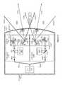
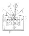
- FIGS. 17-18each illustrate an example enclosure that contains two lidar sensors.
- FIG. 19illustrates two example scan patterns which are out of synchronization with respect to one another.
- FIG. 20illustrates two example scan-pattern y-components which are inverted with respect to one another.
- FIG. 21illustrates two example scan-pattern y-components which are offset from one another by a phase shift ⁇ y .
- FIG. 22illustrates two example scan-pattern x-components which are offset from one another by a phase shift ⁇ x .
- FIG. 23illustrates two example scan patterns.
- FIG. 24illustrates an example computer system.
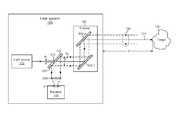
- FIG. 1illustrates an example light detection and ranging (lidar) system 100 .
- a lidar system 100may be referred to as a laser ranging system, a laser radar system, a LIDAR system, a lidar sensor, or a laser detection and ranging (LADAR or ladar) system.
- a lidar system 100may include a light source 110 , mirror 115 , scanner 120 , receiver 140 , or controller 150 .
- the light source 110may be, for example, a laser which emits light having a particular operating wavelength in the infrared, visible, or ultraviolet portions of the electromagnetic spectrum.
- light source 110may include a laser with an operating wavelength between approximately 1.2 ⁇ m and 1.7 ⁇ m.
- the light source 110emits an output beam of light 125 which may be continuous-wave, pulsed, or modulated in any suitable manner for a given application.
- the output beam of light 125is directed downrange toward a remote target 130 .
- the remote target 130may be located a distance D of approximately 1 m to 1 km from the lidar system 100 .
- the targetmay scatter or reflect at least a portion of light from the output beam 125 , and some of the scattered or reflected light may return toward the lidar system 100 .
- the scattered or reflected lightis represented by input beam 135 , which passes through scanner 120 and is directed by mirror 115 to receiver 140 .
- a relatively small fraction of the light from output beam 125may return to the lidar system 100 as input beam 135 .
- the ratio of input beam 135 average power, peak power, or pulse energy to output beam 125 average power, peak power, or pulse energymay be approximately 10 ⁇ 1 , 10 ⁇ 2 , 10 ⁇ 3 , 10 ⁇ 4 10 ⁇ 5 , 10 ⁇ 6 , 10 ⁇ 7 , 10 ⁇ 8 , 10 ⁇ 9 , 10 ⁇ 10 , 10 ⁇ 11 , or 10 ⁇ 12 .
- a pulse of output beam 125has a pulse energy of 1 microjoule ( ⁇ J)
- the pulse energy of a corresponding pulse of input beam 135may have a pulse energy of approximately 10 nanojoules (nJ), 1 nJ, 100 picojoules (pJ), 10 pJ, 1 pJ, 100 femtojoules (fJ), 10 fJ, 1 fJ, 100 attojoules (aJ), 10 aJ, or 1 aJ.
- output beam 125may be referred to as a laser beam, light beam, optical beam, emitted beam, or beam.
- input beam 135may be referred to as a return beam, received beam, return light, received light, input light, scattered light, or reflected light.
- scattered lightmay refer to light that is scattered or reflected by a target 130 .
- an input beam 135may include: light from the output beam 125 that is scattered by target 130 ; light from the output beam 125 that is reflected by target 130 ; or a combination of scattered and reflected light from target 130 .
- receiver 140may receive or detect photons from input beam 135 and generate one or more representative signals. For example, the receiver 140 may generate an output electrical signal 145 that is representative of the input beam 135 . This electrical signal 145 may be sent to controller 150 .
- controller 150may include a processor, computing system (e.g., an ASIC or FPGA), or other suitable circuitry configured to analyze one or more characteristics of the electrical signal 145 from the receiver 140 to determine one or more characteristics of the target 130 , such as its distance downrange from the lidar system 100 . This can be done, for example, by analyzing the time of flight or phase modulation for a beam of light 125 transmitted by the light source 110 .
- a distance D from lidar system 100 to a target 130may be referred to as a distance, depth, or range of target 130 .
- the speed of light crefers to the speed of light in any suitable medium, such as for example in air, water, or vacuum.
- the speed of light in vacuumis approximately 2.9979 ⁇ 10 8 m/s
- the speed of light in air(which has a refractive index of approximately 1.0003) is approximately 2.9970 ⁇ 10 8 m/s.
- light source 110may include a pulsed laser.
- light source 110may be a pulsed laser configured to produce or emit pulses of light with a pulse duration or pulse width of approximately 10 picoseconds (ps) to 20 nanoseconds (ns).
- light source 110may be a pulsed laser that produces pulses with a pulse duration of approximately 200-400 ps.
- light source 110may be a pulsed laser that produces pulses at a pulse repetition frequency of approximately 100 kHz to 5 MHz or a pulse period (e.g., a time between consecutive pulses) of approximately 200 ns to 10 ⁇ s.
- light source 110may have a substantially constant pulse repetition frequency, or light source 110 may have a variable or adjustable pulse repetition frequency.
- light source 110may be a pulsed laser that produces pulses at a substantially constant pulse repetition frequency of approximately 640 kHz (e.g., 640,000 pulses per second), corresponding to a pulse period of approximately 1.56 as.
- light source 110may have a pulse repetition frequency that can be varied from approximately 500 kHz to 3 MHz.
- a pulse of lightmay be referred to as an optical pulse, a light pulse, or a pulse.
- light source 110may produce a free-space output beam 125 having any suitable average optical power, and the output beam 125 may have optical pulses with any suitable pulse energy or peak optical power.
- output beam 125may have an average power of approximately 1 mW, 10 mW, 100 mW, 1 W, 10 W, or any other suitable average power.
- output beam 125may include pulses with a pulse energy of approximately 0.1 ⁇ J, 1 ⁇ J, 10 ⁇ J, 100 ⁇ J, 1 mJ, or any other suitable pulse energy.
- output beam 125may include pulses with a peak power of approximately 10 W, 100 W, 1 kW, 5 kW, 10 kW, or any other suitable peak power.
- An optical pulse with a duration of 400 ps and a pulse energy of 1 ⁇ Jhas a peak power of approximately 2.5 kW. If the pulse repetition frequency is 500 kHz, then the average power of an output beam 125 with 1- ⁇ J pulses is approximately 0.5 W.
- light source 110may include a laser diode, such as for example, a Fabry-Perot laser diode, a quantum well laser, a distributed Bragg reflector (DBR) laser, a distributed feedback (DFB) laser, or a vertical-cavity surface-emitting laser (VCSEL).
- a laser diodesuch as for example, a Fabry-Perot laser diode, a quantum well laser, a distributed Bragg reflector (DBR) laser, a distributed feedback (DFB) laser, or a vertical-cavity surface-emitting laser (VCSEL).
- light source 110may include an aluminum-gallium-arsenide (AlGaAs) laser diode, an indium-gallium-arsenide (InGaAs) laser diode, or an indium-gallium-arsenide-phosphide (InGaAsP) laser diode.
- AlGaAsaluminum-gallium-arsen
- light source 110may include a pulsed laser diode with a peak emission wavelength of approximately 1400-1600 nm.
- light source 110may include a laser diode that is current modulated to produce optical pulses.
- light source 110may include a pulsed laser diode followed by one or more optical-amplification stages.
- light source 110may be a fiber-laser module that includes a current-modulated laser diode with a peak wavelength of approximately 1550 nm followed by a single-stage or a multi-stage erbium-doped fiber amplifier (EDFA).
- EDFAerbium-doped fiber amplifier
- light source 110may include a continuous-wave (CW) or quasi-CW laser diode followed by an external optical modulator (e.g., an electro-optic modulator), and the output of the modulator may be fed into an optical amplifier.
- CWcontinuous-wave
- an electro-optic modulatore.g., an electro-optic modulator
- an output beam of light 125 emitted by light source 110may be a collimated optical beam with any suitable beam divergence, such as for example, a divergence of approximately 0.1 to 3.0 milliradian (mrad).
- a divergence of output beam 125may refer to an angular measure of an increase in beam size (e.g., a beam radius or beam diameter) as output beam 125 travels away from light source 110 or lidar system 100 .
- output beam 125may have a substantially circular cross section with a beam divergence characterized by a single divergence value.
- an output beam 125 with a circular cross section and a divergence of 1 mradmay have a beam diameter or spot size of approximately 10 cm at a distance of 100 m from lidar system 100 .
- output beam 125may be an astigmatic beam or may have a substantially elliptical cross section and may be characterized by two divergence values.
- output beam 125may have a fast axis and a slow axis, where the fast-axis divergence is greater than the slow-axis divergence.
- output beam 125may be an astigmatic beam with a fast-axis divergence of 2 mrad and a slow-axis divergence of 0.5 mrad.
- an output beam of light 125 emitted by light source 110may be unpolarized or randomly polarized, may have no specific or fixed polarization (e.g., the polarization may vary with time), or may have a particular polarization (e.g., output beam 125 may be linearly polarized, elliptically polarized, or circularly polarized).
- light source 110may produce linearly polarized light
- lidar system 100may include a quarter-wave plate that converts this linearly polarized light into circularly polarized light.
- the circularly polarized lightmay be transmitted as output beam 125 , and lidar system 100 may receive input beam 135 , which may be substantially or at least partially circularly polarized in the same manner as the output beam 125 (e.g., if output beam 125 is right-hand circularly polarized, then input beam 135 may also be right-hand circularly polarized).
- the input beam 135may pass through the same quarter-wave plate (or a different quarter-wave plate) resulting in the input beam 135 being converted to linearly polarized light which is orthogonally polarized (e.g., polarized at a right angle) with respect to the linearly polarized light produced by light source 110 .
- lidar system 100may employ polarization-diversity detection where two polarization components are detected separately.
- the output beam 125may be linearly polarized, and the lidar system 100 may split the input beam 135 into two polarization components (e.g., s-polarization and p-polarization) which are detected separately by two photodiodes (e.g., a balanced photoreceiver that includes two photodiodes).
- two polarization componentse.g., s-polarization and p-polarization
- two photodiodese.g., a balanced photoreceiver that includes two photodiodes.
- lidar system 100may include one or more optical components configured to condition, shape, filter, modify, steer, or direct the output beam 125 or the input beam 135 .
- lidar system 100may include one or more lenses, mirrors, filters (e.g., bandpass or interference filters), beam splitters, polarizers, polarizing beam splitters, wave plates (e.g., half-wave or quarter-wave plates), diffractive elements, or holographic elements.
- lidar system 100may include a telescope, one or more lenses, or one or more mirrors to expand, focus, or collimate the output beam 125 to a desired beam diameter or divergence.
- the lidar system 100may include one or more lenses to focus the input beam 135 onto an active region of receiver 140 .
- the lidar system 100may include one or more flat mirrors or curved mirrors (e.g., concave, convex, or parabolic mirrors) to steer or focus the output beam 125 or the input beam 135 .
- the lidar system 100may include an off-axis parabolic mirror to focus the input beam 135 onto an active region of receiver 140 .
- the lidar system 100may include mirror 115 (which may be a metallic or dielectric mirror), and mirror 115 may be configured so that light beam 125 passes through the mirror 115 .
- mirror 115(which may be referred to as an overlap mirror, superposition mirror, or beam-combiner mirror) may include a hole, slot, or aperture which output light beam 125 passes through.
- mirror 115may be configured so that at least 80% of output beam 125 passes through mirror 115 and at least 80% of input beam 135 is reflected by mirror 115 .
- mirror 115may provide for output beam 125 and input beam 135 to be substantially coaxial so that the two beams travel along substantially the same optical path (albeit in opposite directions).
- lidar system 100may include a scanner 120 to steer the output beam 125 in one or more directions downrange.
- scanner 120may include one or more scanning mirrors that are configured to rotate, tilt, pivot, or move in an angular manner about one or more axes.
- a flat scanning mirrormay be attached to a scanner actuator or mechanism which scans the mirror over a particular angular range.
- scanner 120may include a galvanometer scanner, a resonant scanner, a piezoelectric actuator, a polygonal scanner, a rotating-prism scanner, a voice coil motor, a DC motor, a stepper motor, or a microelectromechanical systems (MEMS) device, or any other suitable actuator or mechanism.
- MEMSmicroelectromechanical systems
- scanner 120may be configured to scan the output beam 125 over a 5-degree angular range, 20-degree angular range, 30-degree angular range, 60-degree angular range, or any other suitable angular range.
- a scanning mirrormay be configured to periodically rotate over a 15-degree range, which results in the output beam 125 scanning across a 30-degree range (e.g., a 0-degree rotation by a scanning mirror results in a 20-degree angular scan of output beam 125 ).
- a field of regard (FOR) of a lidar system 100may refer to an area, region, or angular range over which the lidar system 100 may be configured to scan or capture distance information.
- a lidar system 100 with an output beam 125 with a 30-degree scanning rangemay be referred to as having a 30-degree angular field of regard.
- a lidar system 100 with a scanning mirror that rotates over a 30-degree rangemay produce an output beam 125 that scans across a 60-degree range (e.g., a 60-degree FOR).
- lidar system 100may have a FOR of approximately 10°, 20°, 40°, 60°, 120°, or any other suitable FOR.
- a FORmay be referred to as a scan region.
- scanner 120may be configured to scan the output beam 125 horizontally and vertically, and lidar system 100 may have a particular FOR along the horizontal direction and another particular FOR along the vertical direction.
- lidar system 100may have a horizontal FOR of 10° to 120° and a vertical FOR of 2° to 45°.
- scanner 120may include a first mirror and a second mirror, where the first mirror directs the output beam 125 toward the second mirror, and the second mirror directs the output beam 125 downrange.
- the first mirrormay scan the output beam 125 along a first direction
- the second mirrormay scan the output beam 125 along a second direction that is substantially orthogonal to the first direction.
- the first mirrormay scan the output beam 125 along a substantially horizontal direction
- the second mirrormay scan the output beam 125 along a substantially vertical direction (or vice versa).
- scanner 120may be referred to as a beam scanner, optical scanner, or laser scanner.
- one or more scanning mirrorsmay be communicatively coupled to controller 150 which may control the scanning mirror(s) so as to guide the output beam 125 in a desired direction downrange or along a desired scan pattern.
- a scan pattern(which may be referred to as an optical scan pattern, optical scan path, or scan path) may refer to a pattern or path along which the output beam 125 is directed.
- scanner 120may include two scanning mirrors configured to scan the output beam 125 across a 60° horizontal FOR and a 20° vertical FOR. The two scanner mirrors may be controlled to follow a scan path that substantially covers the 60° ⁇ 20° FOR. As an example, the scan path may result in a point cloud with pixels that substantially cover the 60° ⁇ 20° FOR.
- the pixelsmay be approximately evenly distributed across the 60° ⁇ 20° FOR. Alternately, the pixels may have a particular nonuniform distribution (e.g., the pixels may be distributed across all or a portion of the 60° ⁇ 20° FOR, and the pixels may have a higher density in one or more particular regions of the 60° ⁇ 20° FOR).
- a light source 110may emit pulses of light which are scanned by scanner 120 across a FOR of lidar system 100 .
- One or more of the emitted pulses of lightmay be scattered by a target 130 located downrange from the lidar system 100 , and a receiver 140 may detect at least a portion of the pulses of light scattered by the target 130 .
- receiver 140may be referred to as a photoreceiver, optical receiver, optical sensor, detector, photodetector, or optical detector.
- lidar system 100may include a receiver 140 that receives or detects at least a portion of input beam 135 and produces an electrical signal that corresponds to input beam 135 .
- receiver 140may produce an electrical current or voltage pulse that corresponds to the optical pulse detected by receiver 140 .
- receiver 140may include one or more avalanche photodiodes (APDs) or one or more single-photon avalanche diodes (SPADs).
- APDsavalanche photodiodes
- SPADssingle-photon avalanche diodes
- receiver 140may include one or more PN photodiodes (e.g., a photodiode structure formed by a p-type semiconductor and a n-type semiconductor) or one or more PIN photodiodes (e.g., a photodiode structure formed by an undoped intrinsic semiconductor region located between p-type and n-type regions).
- Receiver 140may have an active region or an avalanche-multiplication region that includes silicon, germanium, or InGaAs.
- the active region of receiver 140may have any suitable size, such as for example, a diameter or width of approximately 50-500 am.
- receiver 140may include circuitry that performs signal amplification, sampling, filtering, signal conditioning, analog-to-digital conversion, time-to-digital conversion, pulse detection, threshold detection, rising-edge detection, or falling-edge detection.
- receiver 140may include a transimpedance amplifier that converts a received photocurrent (e.g., a current produced by an APD in response to a received optical signal) into a voltage signal.
- the voltage signalmay be sent to pulse-detection circuitry that produces an analog or digital output signal 145 that corresponds to one or more characteristics (e.g., rising edge, falling edge, amplitude, or duration) of a received optical pulse.
- the pulse-detection circuitrymay perform a time-to-digital conversion to produce a digital output signal 145 .
- the electrical output signal 145may be sent to controller 150 for processing or analysis (e.g., to determine a time-of-flight value corresponding to a received optical pulse).
- controller 150may be electrically coupled or communicatively coupled to light source 110 , scanner 120 , or receiver 140 .
- controller 150may receive electrical trigger pulses or edges from light source 110 , where each pulse or edge corresponds to the emission of an optical pulse by light source 110 .
- controller 150may provide instructions, a control signal, or a trigger signal to light source 110 indicating when light source 110 should produce optical pulses.
- Controller 150may send an electrical trigger signal that includes electrical pulses, where each electrical pulse results in the emission of an optical pulse by light source 110 .
- the frequency, period, duration, pulse energy, peak power, average power, or wavelength of the optical pulses produced by light source 110may be adjusted based on instructions, a control signal, or trigger pulses provided by controller 150 .
- controller 150may be coupled to light source 110 and receiver 140 , and controller 150 may determine a time-of-flight value for an optical pulse based on timing information associated with when the pulse was emitted by light source 110 and when a portion of the pulse (e.g., input beam 135 ) was detected or received by receiver 140 .
- controller 150may include circuitry that performs signal amplification, sampling, filtering, signal conditioning, analog-to-digital conversion, time-to-digital conversion, pulse detection, threshold detection, rising-edge detection, or falling-edge detection.
- a lidar system 100may be used to determine the distance to one or more downrange targets 130 .
- the systemcan be used to map the distance to a number of points within the field of regard.
- Each of these depth-mapped pointsmay be referred to as a pixel.
- a collection of pixels captured in succession(which may be referred to as a depth map, a point cloud, or a frame) may be rendered as an image or may be analyzed to identify or detect objects or to determine a shape or distance of objects within the FOR.
- a depth mapmay cover a field of regard that extends 60° horizontally and 15° vertically, and the depth map may include a frame of 100-2000 pixels in the horizontal direction by 4-400 pixels in the vertical direction.
- lidar system 100may be configured to repeatedly capture or generate point clouds of a field of regard at any suitable frame rate between approximately 0.1 frames per second (FPS) and approximately 1,000 FPS.
- lidar system 100may generate point clouds at a frame rate of approximately 0.1 FPS, 0.5 FPS, 1 FPS, 2 FPS, 5 FPS, 10 FPS, 20 FPS, 100 FPS, 500 FPS, or 1,000 FPS.
- lidar system 100may be configured to produce optical pulses at a rate of 5 ⁇ 10 5 pulses/second (e.g., the system may determine 500,000 pixel distances per second) and scan a frame of 1000 ⁇ 50 pixels (e.g., 50,000 pixels/frame), which corresponds to a point-cloud frame rate of 10 frames per second (e.g., 10 point clouds per second).
- a point-cloud frame ratemay be substantially fixed, or a point-cloud frame rate may be dynamically adjustable.
- a lidar system 100may capture one or more point clouds at a particular frame rate (e.g., 1 Hz) and then switch to capture one or more point clouds at a different frame rate (e.g., 10 Hz).
- a slower frame ratee.g., 1 Hz
- a faster frame ratee.g., 10 Hz
- a lidar system 100may be configured to sense, identify, or determine distances to one or more targets 130 within a field of regard.
- a lidar system 100may determine a distance to a target 130 , where all or part of the target 130 is contained within a field of regard of the lidar system 100 .
- All or part of a target 130 being contained within a FOR of the lidar system 100may refer to the FOR overlapping, encompassing, or enclosing at least a portion of the target 130 .
- target 130may include all or part of an object that is moving or stationary relative to lidar system 100 .
- target 130may include all or a portion of a person, vehicle, motorcycle, truck, train, bicycle, wheelchair, pedestrian, animal, road sign, traffic light, lane marking, road-surface marking, parking space, pylon, guard rail, traffic barrier, pothole, railroad crossing, obstacle in or near a road, curb, stopped vehicle on or beside a road, utility pole, house, building, trash can, mailbox, tree, any other suitable object, or any suitable combination of all or part of two or more objects.
- one or more lidar systems 100may be integrated into a vehicle.
- multiple lidar systems 100may be integrated into a car to provide a complete 360-degree horizontal FOR around the car.
- 6-10 lidar systems 100each system having a 45-degree to 90-degree horizontal FOR, may be combined together to form a sensing system that provides a point cloud covering a 360-degree horizontal FOR.
- the lidar systems 100may be oriented so that adjacent FORs have an amount of spatial or angular overlap to allow data from the multiple lidar systems 100 to be combined or stitched together to form a single or continuous 360-degree point cloud.
- the FOR of each lidar system 100may have approximately 1-15 degrees of overlap with an adjacent FOR.
- a vehiclemay refer to a mobile machine configured to transport people or cargo.
- a vehiclemay include, may take the form of, or may be referred to as a car, automobile, motor vehicle, truck, bus, van, trailer, off-road vehicle, farm vehicle, lawn mower, construction equipment, golf cart, motorhome, taxi, motorcycle, scooter, bicycle, skateboard, train, snowmobile, watercraft (e.g., a ship or boat), aircraft (e.g., a fixed-wing aircraft, helicopter, or dirigible), or spacecraft.
- a vehiclemay include an internal combustion engine or an electric motor that provides propulsion for the vehicle.
- one or more lidar systems 100may be included in a vehicle as part of an advanced driver assistance system (ADAS) to assist a driver of the vehicle in the driving process.
- a lidar system 100may be part of an ADAS that provides information or feedback to a driver (e.g., to alert the driver to potential problems or hazards) or that automatically takes control of part of a vehicle (e.g., a braking system or a steering system) to avoid collisions or accidents.
- a lidar system 100may be part of a vehicle ADAS that provides adaptive cruise control, automated braking, automated parking, collision avoidance, alerts the driver to hazards or other vehicles, maintains the vehicle in the correct lane, or provides a warning if an object or another vehicle is in a blind spot.
- one or more lidar systems 100may be integrated into a vehicle as part of an autonomous-vehicle driving system.
- a lidar system 100may provide information about the surrounding environment to a driving system of an autonomous vehicle.
- An autonomous-vehicle driving systemmay include one or more computing systems that receive information from a lidar system 100 about the surrounding environment, analyze the received information, and provide control signals to the vehicle's driving systems (e.g., steering wheel, accelerator, brake, or turn signal).
- a lidar system 100 integrated into an autonomous vehiclemay provide an autonomous-vehicle driving system with a point cloud every 0.1 seconds (e.g., the point cloud has a 10 Hz update rate, representing 10 frames per second).
- the autonomous-vehicle driving systemmay analyze the received point clouds to sense or identify targets 130 and their respective locations, distances, or speeds, and the autonomous-vehicle driving system may update control signals based on this information. As an example, if lidar system 100 detects a vehicle ahead that is slowing down or stopping, the autonomous-vehicle driving system may send instructions to release the accelerator and apply the brakes.
- an autonomous vehiclemay be referred to as an autonomous car, driverless car, self-driving car, robotic car, or unmanned vehicle.
- an autonomous vehiclemay refer to a vehicle configured to sense its environment and navigate or drive with little or no human input.
- an autonomous vehiclemay be configured to drive to any suitable location and control or perform all safety-critical functions (e.g., driving, steering, braking, parking) for the entire trip, with the driver not expected to control the vehicle at any time.
- an autonomous vehiclemay allow a driver to safely turn their attention away from driving tasks in particular environments (e.g., on freeways), or an autonomous vehicle may provide control of a vehicle in all but a few environments, requiring little or no input or attention from the driver.
- an autonomous vehiclemay be configured to drive with a driver present in the vehicle, or an autonomous vehicle may be configured to operate the vehicle with no driver present.
- an autonomous vehiclemay include a driver's seat with associated controls (e.g., steering wheel, accelerator pedal, and brake pedal), and the vehicle may be configured to drive with no one seated in the driver's seat or with little or no input from a person seated in the driver's seat.
- an autonomous vehiclemay not include any driver's seat or associated driver's controls, and the vehicle may perform substantially all driving functions (e.g., driving, steering, braking, parking, and navigating) without human input.
- an autonomous vehiclemay be configured to operate without a driver (e.g., the vehicle may be configured to transport human passengers or cargo without a driver present in the vehicle).
- an autonomous vehiclemay be configured to operate without any human passengers (e.g., the vehicle may be configured for transportation of cargo without having any human passengers onboard the vehicle).
- FIG. 2illustrates an example scan pattern 200 produced by a lidar system 100 .
- a lidar system 100may be configured to scan output optical beam 125 along one or more particular scan patterns 200 .
- a scan pattern 200may scan across any suitable field of regard (FOR) having any suitable horizontal FOR (FOR H ) and any suitable vertical FOR (FOR V ).
- FORfield of regard
- a scan pattern 200may have a field of regard represented by angular dimensions (e.g., FOR H ⁇ FOR V ) 40° ⁇ 30°, 90° ⁇ 40°, or 60° ⁇ 15°.
- a scan pattern 200may have a FOR H greater than or equal to 10°, 25°, 30°, 40°, 60°, 90°, or 120°.
- a scan pattern 200may have a FOR V greater than or equal to 2°, 5°, 10°, 15°, 20°, 30°, or 45°.
- reference line 220represents a center of the field of regard of scan pattern 200 .
- reference line 220may have any suitable orientation, such as for example, a horizontal angle of 0° (e.g., reference line 220 may be oriented straight ahead) and a vertical angle of 0° (e.g., reference line 220 may have an inclination of 0°), or reference line 220 may have a nonzero horizontal angle or a nonzero inclination (e.g., a vertical angle of +10° or ⁇ 10°).
- a horizontal angle of 0°e.g., reference line 220 may be oriented straight ahead
- a vertical angle of 0°e.g., reference line 220 may have an inclination of 0°
- reference line 220may have a nonzero horizontal angle or a nonzero inclination
- optical beam 125 in FIG. 2has an orientation of approximately ⁇ 15° horizontal and +3° vertical with respect to reference line 220 .
- Optical beam 125may be referred to as having an azimuth of ⁇ 15° and an altitude of +3° relative to reference line 220 .
- an azimuth(which may be referred to as an azimuth angle) may represent a horizontal angle with respect to reference line 220
- an altitude(which may be referred to as an altitude angle, elevation, or elevation angle) may represent a vertical angle with respect to reference line 220 .
- a scan pattern 200may include multiple pixels 210 , and each pixel 210 may be associated with one or more laser pulses and one or more corresponding distance measurements.
- a cycle of scan pattern 200may include a total of P x ⁇ P y pixels 210 (e.g., a two-dimensional distribution of P x by P y pixels).
- scan pattern 200may include a distribution with dimensions of approximately 100-2,000 pixels 210 along a horizontal direction and approximately 4-400 pixels 210 along a vertical direction.
- scan pattern 200may include a distribution of 1,000 pixels 210 along the horizontal direction by 64 pixels 210 along the vertical direction (e.g., the frame size is 1000 ⁇ 64 pixels) for a total of 64,000 pixels per cycle of scan pattern 200 .
- the number of pixels 210 along a horizontal directionmay be referred to as a horizontal resolution of scan pattern 200
- the number of pixels 210 along a vertical directionmay be referred to as a vertical resolution.
- scan pattern 200may have a horizontal resolution of greater than or equal to 100 pixels 210 and a vertical resolution of greater than or equal to 4 pixels 210 .
- scan pattern 200may have a horizontal resolution of 100-2,000 pixels 210 and a vertical resolution of 4-400 pixels 210 .
- each pixel 210may be associated with a distance (e.g., a distance to a portion of a target 130 from which an associated laser pulse was scattered) or one or more angular values.
- a pixel 210may be associated with a distance value and two angular values (e.g., an azimuth and altitude) that represent the angular location of the pixel 210 with respect to the lidar system 100 .
- a distance to a portion of target 130may be determined based at least in part on a time-of-flight measurement for a corresponding pulse.
- An angular value(e.g., an azimuth or altitude) may correspond to an angle (e.g., relative to reference line 220 ) of output beam 125 (e.g., when a corresponding pulse is emitted from lidar system 100 ) or an angle of input beam 135 (e.g., when an input signal is received by lidar system 100 ).
- an angular valuemay be determined based at least in part on a position of a component of scanner 120 .
- an azimuth or altitude value associated with a pixel 210may be determined from an angular position of one or more corresponding scanning mirrors of scanner 120 .
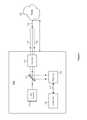
- FIG. 3illustrates an example lidar system 100 with an example overlap mirror 115 .
- a lidar system 100may include a light source 110 configured to emit pulses of light and a scanner 120 configured to scan at least a portion of the emitted pulses of light across a field of regard.
- the light source 110may include a pulsed solid-state laser or a pulsed fiber laser, and the optical pulses produced by the light source 110 may be directed through aperture 310 of overlap mirror 115 and then coupled to scanner 120 .
- a lidar system 100may include a receiver 140 configured to detect at least a portion of the scanned pulses of light scattered by a target 130 located a distance D from the lidar system 100 .
- one or more pulses of light that are directed downrange from lidar system 100 by scanner 120may scatter off a target 130 , and a portion of the scattered light may propagate back to the lidar system 100 (e.g., as part of input beam 135 ) and be detected by receiver 140 .
- lidar system 100may include one or more processors (e.g., controller 150 ) configured to determine a distance D from the lidar system 100 to a target 130 based at least in part on a round-trip time of flight for an emitted pulse of light to travel from the lidar system 100 to the target 130 and back to the lidar system 100 .
- the target 130may be at least partially contained within a field of regard of the lidar system 100 and located a distance D from the lidar system 100 that is less than or equal to a maximum range R MAX of the lidar system 100 .
- a maximum range (which may be referred to as a maximum distance) of a lidar system 100may refer to the maximum distance over which the lidar system 100 is configured to sense or identify targets 130 that appear in a field of regard of the lidar system 100 .
- the maximum range of lidar system 100may be any suitable distance, such as for example, 25 m, 50 m, 100 m, 200 m, 500 m, or 1 km.
- a lidar system 100 with a 200-m maximum rangemay be configured to sense or identify various targets 130 located up to 200 m away from the lidar system 100 .
- light source 110 , scanner 120 , and receiver 140may be packaged together within a single housing, where a housing may refer to a box, case, or enclosure that holds or contains all or part of a lidar system 100 .
- a lidar-system enclosuremay contain a light source 110 , overlap mirror 115 , scanner 120 , and receiver 140 of a lidar system 100 .
- the lidar-system enclosuremay include a controller 150 , or a controller 150 may be located remotely from the enclosure.
- the lidar-system enclosuremay also include one or more electrical connections for conveying electrical power or electrical signals to or from the enclosure.
- light source 110may include an eye-safe laser.
- An eye-safe lasermay refer to a laser with an emission wavelength, average power, peak power, peak intensity, pulse energy, beam size, beam divergence, or exposure time such that emitted light from the laser presents little or no possibility of causing damage to a person's eyes.
- light source 110may be classified as a Class 1 laser product (as specified by the 60825-1 standard of the International Electrotechnical Commission (IEC)) or a Class I laser product (as specified by Title 21, Section 1040.10 of the United States Code of Federal Regulations (CFR)) that is safe under all conditions of normal use.
- IECInternational Electrotechnical Commission
- CFRUnited States Code of Federal Regulations
- light source 110may include an eye-safe laser (e.g., a Class 1 or a Class I laser) configured to operate at any suitable wavelength between approximately 1400 nm and approximately 2100 nm.
- light source 110may include an eye-safe laser with an operating wavelength between approximately 1400 nm and approximately 1600 nm.
- light source 110may include an eye-safe laser with an operating wavelength between approximately 1530 nm and approximately 1560 nm.
- light source 110may include an eye-safe fiber laser or solid-state laser with an operating wavelength between approximately 1400 nm and approximately 1600 nm.
- scanner 120may include one or more mirrors, where each mirror is mechanically driven by a galvanometer scanner, a resonant scanner, a MEMS device, a voice coil motor, or any suitable combination thereof.
- a galvanometer scanner(which may be referred to as a galvanometer actuator) may include a galvanometer-based scanning motor with a magnet and coil. When an electrical current is supplied to the coil, a rotational force is applied to the magnet, which causes a mirror attached to the galvanometer scanner to rotate. The electrical current supplied to the coil may be controlled to dynamically change the position of the galvanometer mirror.
- a resonant scanner(which may be referred to as a resonant actuator) may include a spring-like mechanism driven by an actuator to produce a periodic oscillation at a substantially fixed frequency (e.g., 1 kHz).
- a MEMS-based scanning devicemay include a mirror with a diameter between approximately 1 and 10 mm, where the mirror is rotated using electromagnetic or electrostatic actuation.
- a voice coil motor(which may be referred to as a voice coil actuator) may include a magnet and coil. When an electrical current is supplied to the coil, a translational force is applied to the magnet, which causes a mirror attached to the magnet to move or rotate.
- a scanner 120may include any suitable number of mirrors driven by any suitable number of mechanical actuators.
- a scanner 120may include a single mirror configured to scan an output beam 125 along a single direction (e.g., a scanner 120 may be a one-dimensional scanner that scans along a horizontal or vertical direction).
- the mirrormay be driven by one actuator (e.g., a galvanometer) or two actuators configured to drive the mirror in a push-pull configuration.
- a scanner 120may include a single mirror that scans an output beam 125 along two directions (e.g., horizontal and vertical).
- the mirrormay be driven by two actuators, where each actuator provides rotational motion along a particular direction or about a particular axis.
- a scanner 120may include two mirrors, where one mirror scans an output beam 125 along a substantially horizontal direction and the other mirror scans the output beam 125 along a substantially vertical direction.
- scanner 120includes two mirrors, mirror 300 - 1 and mirror 300 - 2 .
- Mirror 300 - 1may scan output beam 125 along a substantially horizontal direction
- mirror 300 - 2may scan the output beam 125 along a substantially vertical direction (or vice versa).
- a scanner 120may include two mirrors, where each mirror is driven by a corresponding galvanometer scanner.
- scanner 120may include a galvanometer actuator that scans mirror 300 - 1 along a first direction (e.g., vertical), and scanner 120 may include another galvanometer actuator that scans mirror 300 - 2 along a second direction (e.g., horizontal).
- a scanner 120may include two mirrors, where one mirror is driven by a galvanometer actuator and the other mirror is driven by a resonant actuator.
- a galvanometer actuatormay scan mirror 300 - 1 along a first direction
- a resonant actuatormay scan mirror 300 - 2 along a second direction.
- the first and second scanning directionsmay be substantially orthogonal to one another.
- the first directionmay be substantially vertical, and the second direction may be substantially horizontal, or vice versa.
- a scanner 120may include one mirror driven by two actuators which are configured to scan the mirror along two substantially orthogonal directions.
- one mirrormay be driven along a substantially horizontal direction by a resonant actuator or a galvanometer actuator, and the mirror may also be driven along a substantially vertical direction by a galvanometer actuator.
- a mirrormay be driven along two substantially orthogonal directions by two resonant actuators.
- a scanner 120may include a mirror configured to be scanned along one direction by two actuators arranged in a push-pull configuration.
- Driving a mirror in a push-pull configurationmay refer to a mirror that is driven in one direction by two actuators.
- the two actuatorsmay be located at opposite ends or sides of the mirror, and the actuators may be driven in a cooperative manner so that when one actuator pushes on the mirror, the other actuator pulls on the mirror, and vice versa.
- a mirrormay be driven along a horizontal or vertical direction by two voice coil actuators arranged in a push-pull configuration.
- a scanner 120may include one mirror configured to be scanned along two axes, where motion along each axis is provided by two actuators arranged in a push-pull configuration.
- a mirrormay be driven along a horizontal direction by two resonant actuators arranged in a horizontal push-pull configuration, and the mirror may be driven along a vertical direction by another two resonant actuators arranged in a vertical push-pull configuration.
- a scanner 120may include two mirrors which are driven synchronously so that the output beam 125 is directed along any suitable scan pattern 200 .
- a galvanometer actuatormay drive mirror 300 - 2 with a substantially linear back-and-forth motion (e.g., the galvanometer may be driven with a substantially sinusoidal or triangle-shaped waveform) that causes output beam 125 to trace a substantially horizontal back-and-forth pattern.
- another galvanometer actuatormay scan mirror 300 - 1 along a substantially vertical direction.
- the two galvanometersmay be synchronized so that for every 64 horizontal traces, the output beam 125 makes a single trace along a vertical direction.
- a resonant actuatormay drive mirror 300 - 2 along a substantially horizontal direction
- a galvanometer actuator or a resonant actuatormay scan mirror 300 - 1 along a substantially vertical direction.
- a scanner 120may include one mirror driven by two or more actuators, where the actuators are driven synchronously so that the output beam 125 is directed along a particular scan pattern 200 .
- one mirrormay be driven synchronously along two substantially orthogonal directions so that the output beam 125 follows a scan pattern 200 that includes substantially straight lines.
- a scanner 120may include two mirrors driven synchronously so that the synchronously driven mirrors trace out a scan pattern 200 that includes substantially straight lines.
- the scan pattern 200may include a series of substantially straight lines directed substantially horizontally, vertically, or along any other suitable direction.
- the straight linesmay be achieved by applying a dynamically adjusted deflection along a vertical direction (e.g., with a galvanometer actuator) as an output beam 125 is scanned along a substantially horizontal direction (e.g., with a galvanometer or resonant actuator). If a vertical deflection is not applied, the output beam 125 may trace out a curved path as it scans from side to side. By applying a vertical deflection as the mirror is scanned horizontally, a scan pattern 200 that includes substantially straight lines may be achieved.
- a dynamically adjusted deflection along a vertical directione.g., with a galvanometer actuator
- a substantially horizontal directione.g., with a galvanometer or resonant actuator
- a vertical actuatormay be used to apply both a dynamically adjusted vertical deflection as the output beam 125 is scanned horizontally as well as a discrete vertical offset between each horizontal scan (e.g., to step the output beam 125 to a subsequent row of a scan pattern 200 ).
- lidar system 100produces an output beam 125 and receives light from an input beam 135 .
- the output beam 125which includes at least a portion of the pulses of light emitted by light source 110 , may be scanned across a field of regard.
- the input beam 135may include at least a portion of the scanned pulses of light which are scattered by one or more targets 130 and detected by receiver 140 .
- output beam 125 and input beam 135may be substantially coaxial.
- the input and output beams being substantially coaxialmay refer to the beams being at least partially overlapped or sharing a common propagation axis so that input beam 135 and output beam 125 travel along substantially the same optical path (albeit in opposite directions).
- the input beam 135may follow along with the output beam 125 so that the coaxial relationship between the two beams is maintained.
- a lidar system 100may include an overlap mirror 115 configured to overlap the input beam 135 and output beam 125 so that they are substantially coaxial.
- the overlap mirror 115includes a hole, slot, or aperture 310 which the output beam 125 passes through and a reflecting surface 320 that reflects at least a portion of the input beam 135 toward the receiver 140 .
- the overlap mirror 115may be oriented so that input beam 135 and output beam 125 are at least partially overlapped.
- input beam 135may pass through a lens 330 which focuses the beam onto an active region of the receiver 140 .
- the active regionmay refer to an area over which receiver 140 may receive or detect input light.
- the active regionmay have any suitable size or diameter d, such as for example, a diameter of approximately 25 ⁇ m, 50 ⁇ m, 80 ⁇ m, 100 ⁇ m, 200 ⁇ m, 500 ⁇ m, 1 mm, 2 mm, or 5 mm.
- overlap mirror 115may have a reflecting surface 320 that is substantially flat or the reflecting surface 320 may be curved (e.g., mirror 115 may be an off-axis parabolic mirror configured to focus the input beam 135 onto an active region of the receiver 140 ).
- aperture 310may have any suitable size or diameter ⁇ 1
- input beam 135may have any suitable size or diameter ⁇ 2 , where ⁇ 2 is greater than ⁇ 1 .
- aperture 310may have a diameter ⁇ 1 of approximately 0.2 mm, 0.5 mm, 1 mm, 2 mm, 3 mm, 5 mm, or 10 mm
- input beam 135may have a diameter ⁇ 2 of approximately 2 mm, 5 mm, 10 mm, 15 mm, 20 mm, 30 mm, 40 mm, or 50 mm.
- reflective surface 320 of overlap mirror 115may reflect greater than or equal to 70% of input beam 135 toward the receiver 140 .
- the fraction of input beam 135 directed toward the receiver 140may be expressed as R ⁇ [1 ⁇ ( ⁇ 1 / ⁇ 2 ) 2 ]. For example, if R is 95%, ⁇ 1 is 2 mm, and ⁇ 2 is 10 mm, then approximately 91% of input beam 135 may be directed toward the receiver 140 by reflective surface 320 .
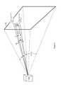
- FIG. 4illustrates an example light-source field of view (FOV L ) and receiver field of view (FOV R ) for a lidar system 100 .
- a light source 110 of lidar system 100may emit pulses of light as the FOV L and FOV R are scanned by scanner 120 across a field of regard (FOR).
- a light-source field of viewmay refer to an angular cone illuminated by the light source 110 at a particular instant of time.
- a receiver field of viewmay refer to an angular cone over which the receiver 140 may receive or detect light at a particular instant of time, and any light outside the receiver field of view may not be received or detected.
- a portion of a pulse of light emitted by the light source 110may be sent downrange from lidar system 100 , and the pulse of light may be sent in the direction that the FOV L is pointing at the time the pulse is emitted.
- the pulse of lightmay scatter off a target 130 , and the receiver 140 may receive and detect a portion of the scattered light that is directed along or contained within the FOV R .
- scanner 120may be configured to scan both a light-source field of view and a receiver field of view across a field of regard of the lidar system 100 .
- Multiple pulses of lightmay be emitted and detected as the scanner 120 scans the FOV L and FOV R across the field of regard of the lidar system 100 while tracing out a scan pattern 200 .
- the light-source field of view and the receiver field of viewmay be scanned synchronously with respect to one another, so that as the FOV L is scanned across a scan pattern 200 , the FOV R follows substantially the same path at the same scanning speed. Additionally, the FOV L and FOV R may maintain the same relative position to one another as they are scanned across the field of regard.
- the FOV Lmay be substantially overlapped with or centered inside the FOV R (as illustrated in FIG. 4 ), and this relative positioning between FOV L and FOV R may be maintained throughout a scan.
- the FOV Rmay lag behind the FOV L by a particular, fixed amount throughout a scan (e.g., the FOV R may be offset from the FOV L in a direction opposite the scan direction).
- the FOV Lmay have an angular size or extent ⁇ L that is substantially the same as or that corresponds to the divergence of the output beam 125
- the FOV Rmay have an angular size or extent ⁇ R that corresponds to an angle over which the receiver 140 may receive and detect light.
- the receiver field of viewmay be any suitable size relative to the light-source field of view. As an example, the receiver field of view may be smaller than, substantially the same size as, or larger than the angular extent of the light-source field of view.
- the light-source field of viewmay have an angular extent of less than or equal to 50 milliradians
- the receiver field of viewmay have an angular extent of less than or equal to 50 milliradians.
- the FOV Lmay have any suitable angular extent ⁇ L , such as for example, approximately 0.1 mrad, 0.2 mrad, 0.5 mrad, 1 mrad, 1.5 mrad, 2 mrad, 3 mrad, 5 mrad, 10 mrad, 20 mrad, 40 mrad, or 50 mrad.
- the FOV Rmay have any suitable angular extent ⁇ R , such as for example, approximately 0.1 mrad, 0.2 mrad, 0.5 mrad, 1 mrad, 1.5 mrad, 2 mrad, 3 mrad, 5 mrad, 10 mrad, 20 mrad, 40 mrad, or 50 mrad.
- the light-source field of view and the receiver field of viewmay have approximately equal angular extents.
- ⁇ L and ⁇ Rmay both be approximately equal to 1 mrad, 2 mrad, or 3 mrad.
- the receiver field of viewmay be larger than the light-source field of view, or the light-source field of view may be larger than the receiver field of view.
- ⁇ Lmay be approximately equal to 1.5 mrad
- ⁇ Rmay be approximately equal to 3 mrad.
- a pixel 210may represent or may correspond to a light-source field of view.
- the diameter of the output beam 125(as well as the size of the corresponding pixel 210 ) may increase according to the beam divergence ⁇ L .
- the output beam 125may have a ⁇ L of 2 mrad
- the output beam 125may have a size or diameter of approximately 20 cm
- a corresponding pixel 210may also have a corresponding size or diameter of approximately 20 cm.
- the output beam 125 and the corresponding pixel 210may each have a diameter of approximately 40 cm.
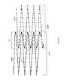
- FIG. 5illustrates an example sinusoidal scan pattern 200 .
- a scan pattern 200may be a closed or continuous scan pattern 200 that continually scans without performing a retrace operation, or a scan pattern 200 may be an open scan pattern 200 that includes a retrace.
- a retrace operationmay occur when scanner 120 resets from an end point of a scan 200 back to a starting point of the scan 200 .
- lidar system 100may not send out pulses or acquire distance data during a retrace, or lidar system 100 may acquire distance data during a retrace (e.g., a retrace path may include one or more pixels 210 ).
- scan pattern 200includes retrace 400 represented by a dashed diagonal line that connects the end of scan pattern 200 to the beginning.
- the pixels 210 of a scan pattern 200may be substantially evenly spaced with respect to time or angle.
- each pixel 210 (and its associated pulse)may be separated from an immediately preceding or following pixel 210 by any suitable time interval, such as for example a time interval of approximately 0.5 ⁇ s, 1.0 ⁇ s, 1.4 ⁇ s, or 2.0 ⁇ s.
- pixels 210 A, 210 B, and 210 Cmay be associated with pulses that were emitted with a 1.6 ⁇ s fixed time interval between the pulses.
- each pixel 210(and its associated pulse) may be separated from an immediately preceding or following pixel 210 by any suitable angle, such as for example an angle of approximately 0.01°, 0.02°, 0.05°, 0.1°, 0.2°, 0.3°, or 0.5°.
- pixels 210 A and 210 Bmay have an angular separation of approximately 0.1° (e.g., pixels 210 A and 210 B may each be associated with optical beams separated by an angle of 0.1°).
- the pixels 210 of a scan pattern 200may have an adjustable spacing with respect to time or angle. As an example, a time interval or angle separating two successive pixels 210 may be dynamically varied during a scan or from one scan to a subsequent scan.
- lidar system 100may include a scanner 120 configured to direct output 125 along any suitable scan pattern 200 .
- all or part of scan pattern 200may follow a substantially sinusoidal path, triangle-wave path, square-wave path, sawtooth path, piecewise linear path, periodic-function path, or any other suitable path or combination of paths.
- scan pattern 200corresponds to an approximately sinusoidal path, where pixels 210 are arranged along a sinusoidal curve.
- scan pattern 200may include any suitable integral number of cycles of a particular periodic function (e.g., 1, 2, 5, 10, 20, 50, or 100 cycles) or any suitable non-integral number of cycles (e.g., 9.7, 13.33, or 53.5 cycles).
- a particular periodic functione.g., 1, 2, 5, 10, 20, 50, or 100 cycles
- non-integral number of cyclese.g. 9.7, 13.33, or 53.5 cycles.
- scan pattern 200includes just over four periods or cycles of a sinusoidal function.
- scan pattern 200may include a periodic function having any suitable alignment or orientation, such as for example, horizontal, vertical, oriented at 33 degrees, or oriented along a 45-degree axis.
- scan pattern 200is a sinusoidal curve oriented horizontally where the peaks and valleys of the sinusoidal curve are aligned substantially horizontally.
- pixels 210may be substantially evenly distributed across scan pattern 200 , or pixels 210 may have a distribution or density that varies across a FOR of scan pattern 200 .
- pixels 210have a greater density toward the left edge 410 L and right edge 410 R of scan 200 , and the pixel density in the middle region 410 M of scan 200 is lower compared to the edges.
- pixels 210may be distributed so that ⁇ 40% of the pixels 210 are located in the left 25% of the FOR of scan pattern 200 (e.g., region 410 L), ⁇ 40% of the pixels 210 are located in the right 25% of the FOR (e.g., region 410 R), and the remaining ⁇ 20% of the pixels 210 are located in the middle 50% of the FOR (e.g., region 410 M).
- a time interval or angle between pixels 210may be dynamically adjusted during a scan so that a scan pattern 200 has a particular distribution of pixels 210 (e.g., a higher density of pixels 210 in one or more particular regions).
- the scan pattern 200may be configured to have a higher density of pixels 210 in a middle or central region of scan 200 or toward one or more edges of scan 200 (e.g., a middle region or a left, right, upper, or lower edge that includes approximately 5%, 10%, 20%, 30%, or any other suitable percentage of the FOR of scan pattern 200 ).
- pixels 210may be distributed so that ⁇ 40% of the pixels 210 are locate in a central, left, or right region of scan pattern 200 with the remaining ⁇ 60% of the pixels 210 distributed throughout the rest of scan pattern 200 .
- a scan pattern 200may have a higher density of pixels along a right edge of the scan pattern 200 than along a left edge of the scan pattern 200 .
- a distribution of pixels 210 in a scan pattern 200may be determined, at least in part, by a pulse period of light source 110 , a scanning speed provided by scanner 120 , or a shape or path followed by scan pattern 200 .
- the pulse period of light source 110may be a substantially fixed value, or the pulse period may be adjusted dynamically during a scan to vary the density of pixels 210 across the scan region.
- an angular speed with which the scanner 120 rotatesmay be substantially fixed or may vary during a scan.
- a scan pattern 200may provide for a varying distribution of pixels 210 based on the shape of the pattern.
- a triangle-wave scan pattern 200(combined with a substantially constant pulse period and angular speed) may provide a substantially uniform distribution of pixels 210 along the horizontal direction, while a sinusoidal scan pattern 200 may result in a higher density of pixels 210 along the left edge 410 L and right edge 410 R and a lower density of pixels 210 in the middle region 410 M.
- two or more scan parametersmay be selected or adjusted to optimize or adjust the density of pixels 210 in a scan pattern 200 .
- a sinusoidal scan pattern 200may be combined with a dynamically adjusted pulse period of light source 100 to provide for a higher density of pixels 210 along the right edge 410 R and a lower density of pixels 210 in the middle region 410 M and left edge 410 L.
- a particular scan pattern 200may be repeated from one scan to the next, or one or more parameters of a scan pattern 200 may be adjusted or varied from one scan to another.
- a time interval or angle between pixels 210may be varied from one scan to another scan.
- a relatively long time intervalmay be applied in an initial scan to produce a moderate-density point cloud, and a relatively short time interval may be applied in a subsequent scan to produce a high-density point cloud.
- a time interval or angle between pixels 210may be varied within a particular scan pattern 200 . For a particular region of a scan pattern 200 , a time interval may be decreased to produce a higher density of pixels 210 within that particular region.
- FIG. 6illustrates an example hybrid scan pattern 200 .
- a hybrid scan pattern 200may be formed by combining portions of two or more scan patterns into a single scan pattern.
- a hybrid scan pattern 200may include any suitable combination of two or more shapes or patterns, such as for example, a sinusoidal shape, triangle-wave shape, square-wave shape, sawtooth shape, circular shape, piecewise linear shape, spiral shape, or any suitable arbitrary shape.
- hybrid scan pattern 200is a combination of a substantially triangle-wave shape (region 420 ) and a substantially sinusoidal shape (region 430 ).
- each particular shape or pattern of a hybrid scan pattern 200may cover any suitable portion of a scan FOR.
- a straight-line region 420may cover 40%, 60%, or 80% of a FOR
- a sinusoidal region 430may cover the remaining 60%, 40%, or 20%, respectively, of the FOR.
- straight-line region 420covers the left 50% of the FOR of scan pattern 200
- sinusoidal region 430covers the right 50% of the FOR.
- pixels 210 for a hybrid scan pattern 200may be distributed along the scan pattern 200 in any suitable uniform or nonuniform manner.
- the pixels 210 in the triangle-wave portion 420 and on the left side of the sinusoidal portion 430have a relatively low-density distribution
- the pixels 210 on the right side of the sinusoidal portion 430have a relatively high-density distribution.
- the hybrid scan pattern 200 of FIG. 6may be used to scan a region where the pixels 210 on the right side of the scan pattern 200 are more important or have a higher relevance than the pixels 210 in the middle or on the left side.
- a hybrid scan pattern 200may be configured so that a particular region (e.g., approximately 10%, 20%, or 30% of the area on the right side of the FOR) includes ⁇ 50% of the pixels 210 and the rest of the scan region (e.g., the remaining 90%, 80%, or 70%, respectively, of the FOR) includes the remaining ⁇ 50% of the pixels 210 .
- a particular regione.g., approximately 10%, 20%, or 30% of the area on the right side of the FOR
- the rest of the scan regione.g., the remaining 90%, 80%, or 70%, respectively, of the FOR
- FIG. 7illustrates two example overlapping scan patterns 200 A and 200 B.
- scan pattern 200 Ais configured to scan across scan region 500 A
- scan pattern 200 Bis configured to scan across scan region 500 B.
- scan patterns 200 A and 200 Bmay each cover a 60° ⁇ 15° FOR.
- two or more scan patterns 200(where each scan pattern is associated with a particular lidar system 100 ) may be configured to scan across two or more respective regions that are at least partially overlapping.
- three overlapping scan patterns 200may be located adjacent to one another (e.g., a first scan region may overlap with a second scan region, and the second scan region may also overlap with a third scan region).
- FIG. 7illustrates two example overlapping scan patterns 200 A and 200 B.
- overlapping scan patterns 200 A and 200 Bmay each include any suitable type of scan pattern having any suitable FOR.
- scan pattern 200 Acorresponds to hybrid scan pattern 200 in FIG. 6
- scan pattern 200 Bcorresponds to a reversed version of scan pattern 200 A (e.g., with respect to scan pattern 200 A, scan pattern 200 B is flipped about a vertical axis).
- Scan pattern 200 Ahas a relatively high density of pixels 210 on the right side of its FOR
- scan pattern 200 Bhas a relatively high density of pixels 210 on the left side of its FOR.
- FIG. 7the example of FIG.
- a retrace path 400is not included for clarity of visualizing the details of the scan patterns 200 A and 200 B.
- a scan pattern 200 illustrated in other figures described hereinmay not include a retrace path 400 , even though in practice the scan pattern 200 may operate with a retrace path 400 that connects the end of the scan pattern 200 to its beginning.
- two scan patterns 200may be configured to overlap in an overlap region 510 where the overlap region 510 has a higher density of pixels 210 than the portions of the scan patterns 200 located outside the overlap region.
- an overlap region 510may include approximately 1%, 5%, 10%, 20%, 30%, or any other suitable portion of scan region 500 A and scan region 500 B.
- an overlap region 510may include approximately 1°, 10°, 20°, or any other suitable angular portion of scan region 500 A and 500 B. If scan regions 500 A and 500 B each have a 60° FOR H and a horizontal angular overlap of approximately 3°, then scan regions 500 A and 500 B may be referred to as having an overlap of approximately 5%.
- An overlap region 510may include a higher density of pixels 210 based at least in part on the overlap of the two scan patterns 200 A and 200 B. As an example, if each scan pattern 200 A and 200 B has a substantially uniform density of pixels 210 across their respective scan region 500 A and 500 B, then the density of pixels 210 in the overlap region 510 may be approximately twice the pixel density outside the overlap region 510 . Additionally, an overlap region 510 may also include a higher density of pixels 210 based on a nonuniform distribution of pixels 210 for each of the scan patterns 200 A and 200 B. As illustrated in FIG. 7 , each scan pattern 200 A and 200 B may be configured to have a higher density of pixels 210 within the overlap region 510 .
- each scan pattern 200 A and 200 Bhas a higher density of pixels 210 within an overlap region 510 , then the density of pixels in the overlap region 510 may be greater than twice the average pixel density outside the overlap region 510 .
- an overlap regionmay have 3 ⁇ , 4 ⁇ , 5 ⁇ , or any other suitable factor of higher pixel density inside an overlap region 510 than an average pixel density outside the overlap region 510 .
- an overlap region 510may include an overlap between 1%, 5%, 10%, 20%, or any other suitable percentage of scan regions 500 A and 500 B, and the overlap region 510 may include 20%, 30%, 40%, 50%, or any other suitable percentage of the total number of pixels 210 of scan patterns 200 A and 200 B.
- FIGS. 8-9each illustrate a top view of a vehicle 610 with two lidar systems 100 A and 100 B that produce two example overlapping scan patterns.
- Scan region 500 Acorresponds to a FOR of lidar system 100 A
- scan region 500 Bcorresponds to a FOR of lidar system 100 B.
- Scan region 500 Ais bordered by lines 600 A-L and 600 A-R, and the angle between lines 600 A-L and 600 A-R corresponds to FOR H-A , the horizontal FOR of scan region 500 A.
- scan region 500 Bis bordered by lines 600 B-L and 600 B-R, and the angle between lines 600 B-L and 600 B-R corresponds to FOR H-B , the horizontal FOR of scan region 500 B.
- Scan region 500 A and scan region 500 Bare overlapped in overlap region 510 .
- overlap region 510is bordered by lines 600 A-R and 600 B-L.
- overlap region 510is bordered by lines 600 A-L and 600 B-R.
- an overlap region 510may provide a higher density of pixels 210 which may result in a higher-density point cloud within the overlap region 510 .
- the relatively high-density parts of scan patterns 200 A and 200 Bmay be configured to coincide approximately with the overlap region 510 , resulting in a further increase in pixel density within the overlap region 510 .
- an overlap region 510may be aimed in a direction with relatively high importance or relevance (e.g., a forward-looking portion of a vehicle), or an overlap region 510 may provide a redundant back-up for an important portion of a FOR.
- lidar sensors 100 A and 100 Bmay be configured to overlap across region 510 , and if one of the lidar sensors (e.g., lidar sensor 100 A) experiences a problem or failure, the other lidar sensor (e.g., lidar sensor 100 B) may continue to scan and produce a point cloud that covers the particular region of interest.
- the lidar sensorse.g., lidar sensor 100 A
- the other lidar sensore.g., lidar sensor 100 B
- scan regions 500 A and 500 Bare overlapped to produce an angularly overlapping scan region 510 that has an overlap angle of ⁇ .
- the overlap angle ⁇corresponds to the angle between lines 600 A-R and 600 B-L, where each line (which may be referred to as a borderline or an edge line) represents a border or end of the scan regions 500 A and 500 B, respectively.
- the overlap angle ⁇ between two scan regionsmay be any suitable angle, such as for example, approximately 0°, 1°, 5°, 10°, 20°, or 40°.
- two scan regions each having a 60° FOR H and an overlap angle ⁇ of 5°may form a combined scan region with an overall FOR H of 115°.
- the overlap angle ⁇ between scan regions 500 A and 500 Bis approximately 20°.
- scan regions 500 A and 500 Bare overlapped to produce a translationally overlapping scan region 510 that has an overlap distance of w.
- a translationally overlapping scan region 510may refer to an overlapping scan region 510 that results from translating scan region 500 A with respect to 500 B.
- the overlap distance w between two scan regionsmay be any suitable value, such as for example, approximately 0 cm, 1 cm, 5 cm, 10 cm, 100 cm, 1 m, 2 m, or 5 m.
- scan regions 500 A and 500 Beach have a 60° FOR and an overlap angle ⁇ of 0°, and the two scan regions together form a combined scan region with an overall FOR of 120°.
- scan regions 500 A and 500 Bmay be angularly overlapped as well as translationally overlapped.
- scan regions 500 A and 500 Bmay have any suitable overlap distance w (e.g., approximately 10 cm) and a nonzero overlap angle ⁇ (e.g., approximately 3°).
- scan regions 500 A and 500 Bmay be overlapped in a crossing or non-crossing manner, depending on the positions of lidar systems 100 A and 100 B and their respective scan regions 500 A and 500 B.
- lidar system 100 Ais located on the left side of vehicle 610
- lidar system 100 Bis located on the right side of vehicle 610 .
- scan region 500 Ais directed toward the left of vehicle 610
- scan region 500 Bis directed toward the right.
- the scan regions 500 A and 500 Bare reversed with respect to FIG. 8 ; scan region 500 A is directed toward the right, and scan region 500 B is directed toward the left.
- scan regions 500 A and 500 Bare overlapped in a non-crossing manner where lidar system 100 A and scan region 500 A are both located on the same side of vehicle 610 (the left side), and lidar system 100 B and scan region 500 B are both located on the other side of vehicle 610 (the right side).
- scan regions 500 A and 500 Bare overlapped in a crossing manner where lidar system 100 A and scan region 500 A are located on opposite sides of vehicle 610 (e.g., lidar system 100 A is located on the left side of vehicle 610 , and scan region 500 A is directed toward the right of vehicle 610 ), and lidar system 100 B and scan region 500 B are also located on opposite sides of vehicle 610 .
- Two lidar systemsmay be non-crossing if they each have one borderline that does not cross either borderline of the other system.
- the two lidar systems 100 A and 100 B in FIG. 8are in a non-crossing configuration since borderline 600 A-L does not cross borderline 600 B-L or 600 B-R, and borderline 600 B-R does not cross borderline 600 A-L or 600 A-R.
- Two lidar systemsmay be overlapped in a crossing manner if the two borderlines for one lidar system each cross at least one borderline of the other lidar system.
- the two lidar systems 100 A and 100 B in FIG. 9are in a crossing configuration since borderline 600 A-L crosses borderline 600 B-L and borderline 600 A-R crosses both borderlines 600 B-L and 600 B-R.
- FIG. 10illustrates an example targeted scan region 810 .
- lidar system 100may be configured to perform a targeted scan 800 over a particular targeted scan region 810 within a particular field of regard FOR H ⁇ FOR V .
- targeted scan pattern 800has a horizontal field of regard 830 contained within FOR H and a vertical field of regard 840 contained within FOR V .
- a full field of regarde.g., FOR H ⁇ FOR V
- the targeted scan region 810may have a field of regard that covers any suitable portion of the full field of regard (e.g., 2° ⁇ 1°, 5° ⁇ 2°, or 10° ⁇ 4°).
- lidar system 100may perform a scan that covers a full field of regard, and then, in a subsequent scan, lidar system 100 may perform a targeted scan 800 to investigate a particular sub-region (e.g., targeted scan region 810 ) of the full field of regard.
- a targeted scan 800to investigate a particular sub-region (e.g., targeted scan region 810 ) of the full field of regard.
- one or more particular regions of interestmay be identified (e.g., there may be a target 130 located in a region of interest), and lidar system 100 may then perform a targeted scan 800 to gain additional information about the target 130 .
- lidar system 100may alternate between performing one or more scans that cover a full field of regard and one or more targeted scans 800 that cover one or more particular sub-regions of the full field of regard.
- a targeted scan 800may have a higher pixel density than a scan that covers a full field of regard.
- a targeted scan 800may cover a targeted scan region 810 having any suitable shape, such as for example, rectangular (as illustrated in FIG. 10 ), square, circular, elliptical, polygonal, or arbitrarily-shaped.
- lidar system 100may perform a single targeted scan 800 of one region 810 (e.g., as illustrated in FIG. 10 ), or lidar system 100 may perform multiple, separate targeted scans 800 .
- lidar system 100may perform two or more targeted scans 800 , where each targeted scan 800 has a particular shape, a particular location within the FOR, a particular scan pattern 800 , or a particular pixel density.
- FIG. 11illustrates an example scan pattern 200 that includes an example targeted scan region 810 .
- a lidar system 100may combine a scan pattern 200 that includes all or part of a full field of regard (e.g., FOR H ⁇ FOR V ) with a targeted scan 800 .
- scan pattern 200may have a relatively low density of pixels 210
- targeted scan 800may have a relatively high density of pixels.
- the average pixel density of the targeted scan 800may be 2 ⁇ , 3 ⁇ , 5 ⁇ , 10 ⁇ , or any other suitable factor greater than the average pixel density of scan pattern 200 .
- an average pixel density of a particular scan regionmay be expressed as M/(FOR H ⁇ FOR V ), where M is the number of pixels 210 within the scan region, and the product of FOR H and FOR V corresponds to the solid angle of the scan region in units of square degrees (deg 2 ).
- Mis the number of pixels 210 within the scan region
- FOR H and FOR Vcorresponds to the solid angle of the scan region in units of square degrees (deg 2 ).
- lidar system 100may perform a standard scan that covers a full field of regard, and then, in a subsequent scan, lidar system 100 may perform a combined standard/targeted scan that includes a scan pattern 200 with a lower density of pixels 210 and a targeted scan 800 with a higher density of pixels 210 .
- a combined standard/targeted scan(e.g., as illustrated in FIG. 11 ) may be performed in two separate steps (e.g., a standard scan pattern 200 may be followed or preceded by a targeted scan 800 ), or a combined standard/targeted scan may be performed in one operation (e.g., all or part of the targeted scan 800 may be performed during or interleaved within the standard scan pattern 200 ).
- a combined standard/targeted scanmay include one or more distinct or separate targeted scan patterns 800 .
- a combined standard/targeted scanmay include a single targeted scan pattern 800 (e.g., as illustrated in FIG. 11 ), or a combined standard/targeted scan may include two or more targeted scan patterns 800 .
- FIGS. 12-13each illustrate an example Lissajous scan pattern 200 .
- a Lissajous scan pattern 200may refer to a scan pattern 200 that at least partially follows or that is based at least in part on a Lissajous curve.
- scanner 120may direct output beam 125 to follow a Lissajous scan pattern 200 where the pattern is based on a Lissajous curve.
- a Lissajous curve(which may be referred to as a Lissajous figure, a Lissajous pattern, or a Lissajous scan pattern) describes a two-dimensional harmonic motion or pattern and may be written as a system of two parametric equations.
- the angles ⁇ x (n) and ⁇ y (n)correspond to an angular location or coordinates of the nth pixel 210 in a scan pattern 200 , and n is an integer that varies from 0 to N ⁇ 1.
- a Lissajous scan pattern 200may traverse a complete scan-pattern cycle that includes N pixels 210 , and then, the Lissajous scan pattern 200 may repeat back on itself and repeatedly retrace approximately the same scan pattern 200 .
- Each of the Lissajous scan patterns 200 illustrated in FIGS. 12-13is a closed scan pattern that repeats back on itself and does not include a retrace operation.
- a pair of angular coordinates ( ⁇ x , ⁇ y )may represent a location of a particular pixel 210 and may correspond to a pointing direction of output beam 125 . In the example of FIG.
- the angular coordinates ( ⁇ x , ⁇ y )have ranges of ( ⁇ 30°, ⁇ 8°).
- the horizontal amplitude Amay be an angle that corresponds to one half of the horizontal field of regard FOR H
- the vertical amplitude Bmay be an angle that corresponds to one half of the vertical field of regard FOR V
- the amplitudes A and Bmay each have any suitable angular value, such as for example, 0.5°, 1°, 2°, 5°, 7.5°, 10°, 15°, 20°, 30°, or 60°. In the example of FIG. 12 , if the field of regard FOR H ⁇ FOR V is 60° ⁇ 16°, then A is 30° and B is 8°.
- phase factor ⁇represents a relative phase shift between the two expressions for ⁇ x (n) and ⁇ y (n), and ⁇ may have any suitable angular value, such as for example, 0°, 5°, 10°, 45°, 90°, or 180°.
- the values a and bmay correspond to a number of horizontal lobes and a number of vertical lobes, respectively, in a Lissajous pattern 200 .
- ais 33
- the Lissajous scan pattern 200may have 33 horizontal lobes (arrayed along a vertical edge of the pattern 200 )
- bis 13
- the Lissajous scan pattern 200may have 13 vertical lobes (arrayed along a horizontal edge).
- a lobecorresponds to an arc of the Lissajous pattern 200 that protrudes along one edge of the pattern 200 (e.g., a left edge, right edge, upper edge, or lower edge).
- lobe 1000 His a horizontal lobe
- lobe 1000 Vis a vertical lobe.
- ais 3 and b is 4, and the Lissajous scan pattern 200 has 3 horizontal lobes and 4 vertical lobes.
- ais 11 and b is 17, and the Lissajous scan pattern 200 has 11 horizontal lobes and 17 vertical lobes.
- the values a and bmay correspond to a number of horizontal and vertical cycles, respectively, in a Lissajous pattern 200 .
- each traversal of the corresponding Lissajous pattern 200may include 12 sinusoidal cycles along a horizontal direction and 5 sinusoidal cycles along a vertical direction (e.g., for each traversal of the Lissajous pattern 200 , a horizontal scanning mirror may undergo 12 periodic cycles, and a vertical scanning mirror may undergo 5 periodic cycles).
- pixels 210are not included in the Lissajous scan pattern 200 for clarity of illustrating the scan pattern.
- scan patterns 200 illustrated in other figures described hereinmay not include pixels for clarity of illustrating the scan pattern.
- the spatial-frequency parameters a and b for a Lissajous scan pattern 200may each have any suitable integer value (e.g., 2, 10, 53, 113, or 200) or any suitable non-integer value (e.g., 5.3, 37.1, or 113.7).
- a and bmay each have an integer value, where a and b do not have any common factors.
- valid (a, b) pairsmay include (2, 7), (3, 8), (11, 14), or (17, 32)
- non-valid (a, b) pairs that have common factorsmay include (2, 6), (3, 9), or (11, 33).
- a Lissajous scan pattern 200may be a static-pixel pattern where each pixel 210 of the scan pattern 200 has substantially the same angular coordinates ( ⁇ x , ⁇ y ) from one scan cycle to the next.
- a Lissajous scan pattern 200may be a dynamic-pixel pattern where the pixels 210 of the scan pattern 200 have angular coordinates ( ⁇ x , ⁇ y ) that vary from one scan cycle to the next.
- the pixels 210may all be located on a curve corresponding to the Lissajous scan pattern 200 , but from one cycle to the next, each pixel 210 may advance along the scan-pattern curve 200 by an amount that depends on a phase-advancement factor.
- the cycle parameter Cis an integer that represents the number of Lissajous-curve scan cycles that have been traversed, and the parameter C increments by 1 for each successive cycle.
- Cis 0, and for the next cycle C is 1.
- the phase-advancement factor ⁇represents an amount of phase increase from one scan cycle to the next and corresponds to an amount of movement along a scan-pattern curve from one scan to the next.
- the phase advancement factor ⁇may have any suitable angular value, such as for example, 0.001°, 0.01°, 0.05°, 0.1°, 0.5°, 1°, 5°, or 10°.
- the other pixels 210 of the scan pattern 200may advance along the scan-pattern curve in a similar fashion.
- the angles ⁇ x (t) and ⁇ y (t)correspond to the angular location or coordinates of output beam 125 at a time t.
- the frame rate f(which may be expressed in units of frames per second, or hertz) may be any suitable value, such as for example, 0.1 Hz, 1 Hz, 5 Hz, 10 Hz, 20 Hz, 40 Hz, 60 Hz, 100 Hz, or 400 Hz.
- the product a ⁇ fcorresponds to the oscillation frequency of the output beam 125 along an x-axis (which may be represented by F x ).
- the product b ⁇ fcorresponds the oscillation frequency of the output beam 125 along a y-axis (which may be represented by F y ).
- the phase difference ⁇ between the angles ⁇ x (t) and ⁇ y (t)may be any suitable fixed or adjustable angular value.
- two scanning mirrors of scanner 120may each oscillate at a particular frequency (e.g., F x and F y ), and the two scanning mirrors may be synchronized with respect to one another so that there is a substantially fixed phase difference ⁇ delta between their oscillations.
- a galvanometer scanner or a resonant-mirror scannermay be configured to scan an output beam 125 along any suitable direction (e.g., horizontally or vertically) at any suitable frequency, such as for example, approximately 1 Hz, 5 Hz, 10 Hz, 20 Hz, 40 Hz, 60 Hz, 100 Hz, 500 Hz, 1 kHz, 2 kHz, 5 kHz, or 10 kHz.
- the first or second mirrormay each be driven by any suitable type of actuator, such as for example, a galvanometer scanner, a resonant scanner, a voice coil motor, or a MEMS device.
- the first and second mirrorsmay each be driven by a resonant scanner configured to oscillate at a particular resonant frequency (e.g., the first mirror may be driven at approximately 1-100 Hz and the second mirror may be driven at approximately 500-1,000 Hz).
- the first mirrormay be driven by a galvanometer scanner, and the second mirror may be driven by a resonant scanner.
- the first and second mirrorsmay each be driven by a galvanometer scanner.
- FIGS. 14-16illustrate three successive stages of an example quasi-non-repeating Lissajous scan pattern 200 .
- a corresponding Lissajous scan pattern 200may be closed (e.g., the pattern repeats back on itself after a finite number of cycles).
- the Lissajous scan patterns 200 illustrated in FIGS. 12-13are closed scan patterns (e.g., the Lissajous scan patterns 200 in FIGS. 12-13 repeat and do not include a retrace operation).
- each scan cycleincludes N pixels 210 .
- the corresponding Lissajous scan pattern 200may be non-repeating (e.g., the pattern never repeats back on itself).
- the scan patterns 200may be closed, but the pattern may require a significant number of scan cycles before repeating back on itself.
- a Lissajous scan pattern 200 that takes greater than or equal to 5, 10, 20, 30, 50, 100, 1000, or any other suitable number of scan cycles before repeating back on itselfmay be referred to as a quasi-non-repeating Lissajous scan pattern 200 .
- a quasi-non-repeating Lissajous scan pattern 200may have a pair of values (a, b) such as (5.01, 4), (17.3, 13), or (11.3, 117.07), where at least one of the values of a or b is a non-integer rational number.
- a quasi-non-repeating Lissajous scan pattern 200may require M scan cycles before repeating back on itself, where M is the smallest integer such that M ⁇ a is an integer and M ⁇ b is an integer.
- Mis the smallest integer such that M ⁇ a is an integer and M ⁇ b is an integer.
- a quasi-non-repeating Lissajous scan pattern 200may be used to provide a more complete coverage of a scan region than a closed scan pattern or may be used to provide a scan pattern where the pixels 210 do not remain fixed in the same location from one scan cycle to another.
- FIGS. 14-16illustrate a quasi-non-repeating Lissajous scan pattern 200 where a is 3.02 and b is 2.
- FIG. 14illustrates the quasi-non-repeating Lissajous scan pattern 200 after approximately one scan cycle. The scan cycle begins at pixel 210 G and proceeds to scan in the direction of the arrows.
- FIG. 15illustrates the quasi-non-repeating Lissajous scan pattern 200 after approximately two scan cycles.
- FIG. 16illustrates the quasi-non-repeating Lissajous scan pattern 200 after approximately 20 scan cycles.
- fis a frame rate of the lidar system 100
- a or bis a non-integer rational number.
- FIGS. 17-18each illustrate an example enclosure 850 that contains two lidar sensors 100 A and 100 B.
- an enclosure 850 that includes two or more lidar sensorsmay be referred to collectively as a lidar system, lidar module, or lidar-system module.
- the enclosure 850contains light source 110 , and light from the light source 110 is directed to lidar sensor 100 A and lidar sensor 100 B by fiber-optic cables 880 A and 880 B, respectively.
- Fiber-optic cable 880 Ais terminated by lens 890 A, which produces free-space beam 125 A.
- fiber-optic cable 880 Bis terminated by lens 890 B, which produces free-space beam 125 B.
- Lens 890 Amay be a fiber-optic collimator that receives light from fiber-optic cable 880 A and produces a free-space optical beam 125 A that is directed through mirror 115 A and to scanner 120 A.
- lens 890 Bmay be a fiber-optic collimator that receives light from fiber-optic cable 880 B and produces a free-space optical beam 125 B.
- each lidar sensor 100 A and 100 Bincludes a dedicated light source 110 A and 110 B, respectively.
- the output beam 125 Apasses through a hole in overlap mirror 115 A and is directed to scanner 120 A
- the output beam 125 Bpasses through a hole in overlap mirror 115 B and is directed to scanner 120 B
- Scanners 120 A and 120 Bscan output beams 125 A and 125 B, respectively, along particular scan patterns.
- the enclosures 850 in FIGS. 17 and 18each include a window 860 which output beams 125 A and 125 B pass through.
- Scattered light 135 A from output beam 125 A(e.g., light that is scattered by a target 130 ) travels back through window 860 and scanner 120 A and is then reflected by mirror 115 A toward receiver 140 A.
- scattered light 135 B from output beam 125 Btravels back through window 860 and scanner 120 B and is then reflected by mirror 115 B toward receiver 140 B.
- scanner 120 Aincludes scanning mirrors 300 A- 1 and 300 A- 2
- scanner 120 Bincludes scanning mirrors 300 B- 1 and 300 B- 2
- Scanning mirror 300 A- 1is rotated to scan output beam 125 A vertically (e.g., output beam 125 A performs an elevation scan along an angle ⁇ Ay )
- scanning mirror 300 A- 2is rotated to scan output beam 125 A horizontally (e.g., output beam 125 A performs an azimuthal scan along an angle ⁇ Ax ).
- each scannerincludes a single scanning mirror configured to rotate about two substantially orthogonal axes.
- Scanner 120 Aincludes scanning mirror 300 A, which scans output beam 125 A vertically and horizontally by scanning along angles ⁇ Ay and ⁇ Ax , respectively.
- scanner 120 Bincludes scanning mirror 300 B, which scans output beam 125 B vertically and horizontally by scanning along angles ⁇ By and ⁇ Bx , respectively.
- the lidar sensors 100 A and 100 B illustrated in FIG. 17 or 18may be similar to the lidar sensors 100 A and 100 B illustrated in FIG. 8 or 9 .
- scan regions 500 A and 500 Bare overlapped in a non-crossing manner (similar to scan regions 500 A and 500 B illustrated in FIG. 8 ).
- scan regions 500 A and 500 Bare overlapped in a crossing manner (similar to scan regions 500 A and 500 B illustrated in FIG. 9 ).
- a lidar systemmay include 2, 3, 4, or any other suitable number of lidar sensors.
- a lidar systemmay include two lidar sensors (e.g., lidar sensors 100 A and 100 B) which are packaged in one enclosure 850 .
- a lidar systemmay include three lidar sensors packaged in one enclosure 850 .
- An enclosure 850may refer to a housing, box, or case that contains two or more lidar sensors.
- An enclosure 850may be an airtight or watertight structure that prevents water vapor, liquid water, dirt, dust, or other contaminants from getting inside the enclosure 850 .
- An enclosure 850may be filled with a dry or inert gas, such as for example, dry air, nitrogen, or argon.
- Each lidar sensor 100 contained within an enclosure 850may include a scanner 120 configured to scan pulses of light (e.g., output beam 125 ) along a particular scan pattern 200 and a receiver 140 configured to detect scattered light 135 from the scanned pulses of light. Additionally, the enclosure 850 may include a window 860 which the output beam 125 and scattered light 135 for each lidar sensor are transmitted through.
- a scanner 120configured to scan pulses of light (e.g., output beam 125 ) along a particular scan pattern 200 and a receiver 140 configured to detect scattered light 135 from the scanned pulses of light.
- the enclosure 850may include a window 860 which the output beam 125 and scattered light 135 for each lidar sensor are transmitted through.
- a lidar system with multiple lidar sensorsmay produce multiple respective scan patterns which are at least partially overlapped.
- a lidar systemmay include two lidar sensors 100 A and 100 B that produce two scan patterns 200 A and 200 B, respectively, where scan patterns 200 A and 200 B are at least partially overlapped (e.g., in a crossing or a non-crossing manner).
- a lidar systemmay include three lidar sensors that produce three respective scan patterns (e.g., a first, second, and third scan pattern) which are at least partially overlapped (e.g., the first and second scan patterns are at least partially overlapped, and the second and third scan patterns are at least partially overlapped).
- a lidar systemmay include one or more light sources 110 configured to provide optical pulses to two or more lidar sensors.
- a single light source 110may be used to supply optical pulses to multiple lidar sensors within an enclosure 850 .
- light source 110produces optical pulses that are split and supplied to lidar sensors 100 A and 100 B.
- optical pulses produced by light source 110may pass through a 1 ⁇ 2 optical-power splitter that splits each pulse emitted by light source 110 into two pulses which are sent to lidar sensor 100 A and lidar sensor 100 B, respectively.
- optical pulses produced by light source 110may pass through a 1 ⁇ 2 optical switch that switches between lidar sensor 100 A and lidar sensor 100 B so that every other emitted pulse is supplied to one of the lidar sensors (e.g., pulses 1 , 3 , 5 , etc. are supplied to lidar sensor 100 A, and pulses 2 , 4 , 6 , etc. are supplied to lidar sensor 100 B).
- optical pulses produced by light source 110may pass through a 1 ⁇ N optical splitter or switch that supplies the pulses to N lidar sensors 100 located within an enclosure 850 .
- a lidar systemmay include multiple light sources 110 configured to provide optical pulses to multiple respective lidar sensors 100 .
- each lidar sensor 100 within a lidar-system enclosure 850may have a dedicated light source 110 .
- light source 110 Asupplies optical pulses for lidar sensor 100 A
- light source 110 Bsupplies optical pulses for lidar sensor 100 B.
- a lidar-system enclosure 850 with multiple lidar sensors 100may produce multiple output beams 125 having one or more particular wavelengths.
- output beams 125 A and 125 Bmay include pulses having substantially the same wavelength (e.g., approximately 1550 nm).
- output beams 125 A and 125 Bmay have different wavelengths.
- light source 110 Amay produce pulses with a wavelength of approximately 1550 nm
- light source 110 Bmay produce pulses with a wavelength of approximately 1555 nm.
- lidar sensor 100 Amay include an optical filter that transmits light at the wavelength of light source 110 A and blocks light at the wavelength of light source 110 B.
- lidar sensor 100 Bmay include an optical filter that transmits light at the wavelength of light source 110 B and blocks light at the wavelength of light source 110 A.
- each receiver 140 A and 140 Bmay have an optical filter located at or near the input to the receiver.
- the optical filtermay be configured to block light from the other light source to reduce optical cross-talk between lidar sensor 100 A and 100 B (e.g., to reduce the amount of scattered light from light source 110 B that is detected by receiver 140 A).
- An optical filtermay be an absorptive filter, dichroic filter, long-pass filter, short-pass filter, band-pass filter, or any other suitable type of optical filter.
- each output beam 125 emitted from an enclosure 850may be incident on window 860 at a nonzero angle of incidence (AOI).
- a beam that is incident at 0° AOImay be approximately orthogonal to surface A or surface B of window 860 .
- output beams 125 A and 125 Bmay each be incident on window 860 at a nonzero AOI (e.g., output beams 125 A and 125 B are each non-orthogonal to surface A and surface B of window 860 as the beams are scanned).
- Output beams 125 A and 125 Bmay each have an AOI with window 860 that is greater than or equal to approximately 0.5°, 1°, 2°, 5°, 10°, 20°, or any other suitable AOI. If output beam 125 A strikes window 860 at 0° AOI, then a portion of the beam 125 A reflected at surface A or surface B may propagate back along approximately the same path as the incident beam 125 A. This specular reflection may be detected by receiver 140 A (e.g., the specular reflection may result in an unwanted pulse-detection event).
- output beam 125 Ahas a nonzero AOI on window 860 as the beam is scanned, then the magnitude of an unwanted specular reflection from window 860 detected by receiver 140 A may be significantly reduced since the off-axis specular reflection will not propagate directly back on the path of the incident beam 125 A.
- output beam 125 Bhas a nonzero AOI on window 860 , then the magnitude of an unwanted specular reflection from window 860 detected by receiver 140 B may be significantly reduced.
- an output beam 125may produce scattered light when the output beam 125 is incident on window 860 .
- the scattered lightmay result from surface roughness, imperfections, impurities, or inhomogeneities located in window 860 or on surface A or surface B.
- output beams 125 A and 125 Bproduce scattered light 870 A and 870 B, respectively, at window 860 .
- Scattered light 870 A or 870 Bmay be produced from surface A, surface B, or from the bulk material of window 860 , and scattered light 870 A and 870 B may be emitted over a wide range of directions.
- a portion of scattered light 870 Amay be detected by receiver 140 B, resulting in unwanted cross-talk from lidar sensor 100 A to lidar sensor 100 B.
- a portion of scattered light 870 Bmay be detected by receiver 140 A, resulting in unwanted optical cross-talk from lidar sensor 100 B to lidar sensor 100 A.
- an amount of optical cross-talk between lidar sensorsmay be reduced by performing scans in an out-of-synchronization manner, as described herein.
- window 860may be made from any suitable substrate material, such as for example, glass or plastic (e.g., polycarbonate, acrylic, cyclic-olefin polymer, or cyclic-olefin copolymer).
- window 860may include an interior surface (surface A) and an exterior surface (surface B), and surface A or surface B may include a dielectric coating having particular reflectivity values at particular wavelengths.
- a dielectric coating(which may be referred to as a thin-film coating, interference coating, or coating) may include one or more thin-film layers of dielectric materials (e.g., SiO 2 , TiO 2 , Al 2 O 3 , Ta 2 O 5 , MgF 2 , LaF 3 , or AlF 3 ) having particular thicknesses (e.g., thickness less than 1 ⁇ m) and particular refractive indices.
- a dielectric coatingmay be deposited onto surface A or surface B of window 860 using any suitable deposition technique, such as for example, sputtering or electron-beam deposition.
- a dielectric coatingmay have a high reflectivity at a particular wavelength or a low reflectivity at a particular wavelength.
- a high-reflectivity (HR) dielectric coatingmay have any suitable reflectivity value (e.g., a reflectivity greater than or equal to 80%, 90%, 95%, or 99%) at any suitable wavelength or combination of wavelengths.
- a low-reflectivity dielectric coating(which may be referred to as an anti-reflection (AR) coating) may have any suitable reflectivity value (e.g., a reflectivity less than or equal to 5%, 2%, 1%, 0.5%, or 0.2%) at any suitable wavelength or combination of wavelengths.
- a dielectric coatingmay be a dichroic coating with a particular combination of high or low reflectivity values at particular wavelengths.
- a dichroic coatingmay have a reflectivity of less than or equal to 0.5% at approximately 1550-1560 nm and a reflectivity of greater than or equal to 90% at approximately 800-1500 nm.
- surface A or surface Bmay have a dielectric coating that is anti-reflecting at an operating wavelength of one or more light sources 110 contained within enclosure 850 .
- An AR coating on surface A and surface Bmay increase the amount of light at an operating wavelength of light source 110 that is transmitted through window 860 .
- an AR coating at an operating wavelength of light source 110may reduce the amount of incident light from output beam 125 A or 125 B that is reflected by window 860 back into the enclosure 850 .
- surface A and surface Bmay each have an AR coating with reflectivity less than 0.5% at an operating wavelength of light source 110 .
- surface A and surface Bmay each have an AR coating with a reflectivity that is less than 0.5% from approximately 1547 nm to approximately 1553 nm.
- surface A and surface Bmay each have an AR coating with reflectivity less than 1% at the operating wavelengths of light sources 110 A and 110 B.
- surface A and surface Bmay each have an AR coating with reflectivity less than 1% from approximately 1530 nm to approximately 1545 nm.
- window 860may have an optical transmission that is greater than any suitable value for one or more wavelengths of one or more light sources 110 contained within enclosure 850 .
- window 860may have an optical transmission of greater than or equal to 70%, 80%, 90%, 95%, or 99% at a wavelength of light source 110 .
- window 860may transmit greater than or equal to 95% of light at an operating wavelength of light source 110 .
- window 860may transmit greater than or equal to 90% of light at the operating wavelengths of light sources 110 A and 110 B.
- surface A or surface Bmay have a dichroic coating that is anti-reflecting at one or more operating wavelengths of one or more light sources 110 and high-reflecting at wavelengths away from the one or more operating wavelengths.
- surface Amay have an AR coating for an operating wavelength of light source 110
- surface Bmay have a dichroic coating that is AR at the light-source operating wavelength and HR for wavelengths away from the operating wavelength.
- a coating that is HR for wavelengths away from a light-source operating wavelengthmay prevent most incoming light at unwanted wavelengths from being transmitted through window 860 .
- surface Amay have an AR coating with a reflectivity of less than or equal to 0.5% from approximately 1546 nm to approximately 1554 nm.
- surface Bmay have a dichroic coating that is AR at approximately 1546-1554 nm and HR (e.g., reflectivity of greater than or equal to 90%) at approximately 800-1500 nm and approximately 1580-1700 nm.
- surface B of window 860may include a coating that is oleophobic, hydrophobic, or hydrophilic.
- a coating that is oleophobic (or, lipophobic)may repel oils (e.g., fingerprint oil or other non-polar material) from the exterior surface (surface B) of window 860 .
- a coating that is hydrophobicmay repel water from the exterior surface.
- surface Bmay be coated with a material that is both oleophobic and hydrophobic.
- a coating that is hydrophilicattracts water so that water may tend to wet and form a film on the hydrophilic surface (rather than forming beads of water as may occur on a hydrophobic surface).
- surface Bhas a hydrophilic coating
- watere.g., from rain
- the surface film of watermay result in less distortion, deflection, or occlusion of an output beam 125 than a surface with a non-hydrophilic coating or a hydrophobic coating.
- FIG. 19illustrates two example scan patterns 200 A and 200 B which are out of synchronization with respect to one another.
- a lidar systemmay include two or more lidar sensors 100 that produce two or more respective scan patterns 200 which are scanned out of synchronization with respect to one another.
- a lidar system that includes two lidar sensors 100 A and 100 B(e.g., the lidar system illustrated in FIG. 17 or 18 ) may produce two scan patterns 200 A and 200 B which are out of synchronization with respect to one another.
- two or more scan patterns 200 that are out of synchronizationmay be referred to as scan patterns 200 that are non-synchronous, non-coincident, inverted, offset, or out of phase.
- scan patterns 200 A and 200 Beach include a substantially sinusoidal back-and-forth scanning portion followed by a diagonal retrace 400 A and 400 B, respectively, that connects the end of a scan pattern with the beginning.
- Scan patterns 200 A and 200 Bperform scans in an inverted sense with respect to one another.
- Scan pattern 200 Ascans from top to bottom (e.g., scan pattern 200 A traces across the following pixels in order: 210 A- 1 , 210 A- 2 , 210 A- 3 , and 210 A- 4 ), and retrace 400 A is directed upward (from bottom to top).
- Scan pattern 200 Bwhich is inverted with respect to scan pattern 200 A, scans from bottom to top (e.g., scan pattern 200 B traces across the following pixels in order: 210 B- 1 , 210 B- 2 , 210 B- 3 , and 210 B- 4 ), and retrace 400 B is directed downward.
- Scan patterns 200 A and 200 B in FIG. 19may each include additional pixels 210 which are not illustrated in the figure.
- scan patterns 200 that are scanned out of synchronization with respect to one anothermay be associated with a reduced amount of optical cross-talk between lidar sensors 100 .
- a portion of cross-talk between lidar sensors 100may be caused by light that is reflected or scattered at window 860 (e.g., a portion of scattered light 870 A from lidar sensor 100 A may be detected by receiver 140 B, or a portion of scattered light 870 B from lidar sensor 100 B may be detected by receiver 140 A).
- the two output beamsmay be directed at locations on window 860 that are mostly non-coincident or non-overlapping, which may reduce the amount of cross-talk light between the two lidar sensors.
- the two output beamsand their associated receiver FOVs
- FIG. 18little to none of the scattered light 870 A from output beam 125 A may be detected by receiver 140 B, since the FOV of receiver 140 B may be directed at a different location on window 860 than the FOV of light source 110 A.
- little to none of the scattered light 870 B from output beam 125 Bmay be detected by receiver 140 A.
- scan patterns 200 A and 200 B being scanned out of synchronization with respect to one anothermay be associated with receiver 140 A detecting substantial cross-talk light from output beam 125 B for less than a particular amount of pixels 210 in scan pattern 200 A.
- receiver 140 Bmay detect substantial cross-talk light from output beam 125 A for less than a particular amount of pixels 210 in scan pattern 200 B.
- the amount of pixels 210 for which substantial cross-talk light is detectedmay be less than or equal to approximately 1, 10, 100, 1,000, or any other suitable number of pixels 210 .
- the amount of pixels 210 for which substantial cross-talk light is detectedmay be less than or equal to approximately 10%, 1%, 0.1%, 0.01%, 0.001%, or any other suitable percentage of pixels 210 in a scan pattern 200 . If scan pattern 200 A includes 50,000 pixels 210 , and approximately 0.1% of the pixels 210 include a substantial amount of cross-talk light from output beam 125 B, then approximately 50 pixels 210 (out of the 50,000 pixels 210 ) may include substantial cross-talk light.
- detection of substantial cross-talk light by receiver 140 Amay refer to the receiver 140 A detecting an amount of light from output beam 125 B that is above a particular threshold value.
- receiver 140 Amay have a particular threshold value that corresponds to a valid detection of a pulse of light. If a voltage signal produced by receiver 140 A (e.g., in response to detecting a pulse of light) exceeds a particular threshold voltage, then the voltage signal may correspond to a valid pulse-detection event (e.g., detection of a pulse of light that is scattered by a target 130 ).
- Detection of substantial cross-talk lightmay result from receiver 140 A detecting cross-talk light from lidar sensor 100 B that exceeds the particular detection-threshold voltage.
- receiver 140 B detecting substantial cross-talk lightmay result from receiver 140 B detecting cross-talk light from lidar sensor 100 A that exceeds the particular detection-threshold voltage.
- a scan pattern 200may include a scan-pattern x-component ( ⁇ x ) and a scan-pattern y-component ( ⁇ y ).
- the x-componentmay correspond to a horizontal (or, azimuthal) angular scan
- the y-componentmay correspond to a vertical (or, elevation) angular scan.
- scan pattern 200 Aincludes a scan-pattern x-component ( ⁇ Ax ) and a scan-pattern y-component ( ⁇ Ay )
- scan pattern 200 Bincludes a scan-pattern x-component ( ⁇ Bx ) and a scan-pattern y-component ( ⁇ By ).
- the scan patterns 200 A and 200 B in FIG. 19may be produced by the lidar system in FIG. 17 , where mirror 300 A- 1 produces the ⁇ Ay scan component, mirror 300 A- 2 produces the ⁇ Ax scan component, mirror 300 B- 1 produces the ⁇ By scan component, and mirror 300 B- 2 produces the ⁇ Bx scan component.
- FIG. 20illustrates two example scan-pattern y-components ⁇ Ay and ⁇ By which are inverted with respect to one another.
- two scan patterns 200 being scanned out of synchronizationmay include one scan-pattern y-component ( ⁇ Ay ) being inverted with respect to the other scan-pattern y-component ( ⁇ By ).
- the ⁇ Ay component in FIG. 20corresponds to the vertical scan component of scan pattern 200 A in FIG. 19
- the ⁇ By component in FIG. 20corresponds to the vertical scan component of scan pattern 200 B in FIG. 19 .
- the scan patterns 200 A and 200 Bare inverted in the sense that scan pattern 200 A scans from top to bottom, and scan pattern 200 B scans in the opposite direction (from bottom to top).
- the fast, positive rampcorresponds to retrace 400 A
- the slow, negative rampcorresponds to the top-to-bottom scan of scan pattern 200 A in FIG. 19
- the fast, negative rampcorresponds to retrace 400 B
- the slow, positive rampcorresponds to the bottom-to-top scan of scan pattern 200 B in FIG. 19 .
- FIG. 21illustrates two example scan-pattern y-components ⁇ Ay and ⁇ By which are offset from one another by a phase shift ⁇ y .
- two scan patterns 200 being scanned out of synchronizationmay include one scan-pattern y-component ( ⁇ Ay ) having a particular phase shift ⁇ y relative to the other scan-pattern y-component ( ⁇ By ).
- each scan-pattern y-component ( ⁇ Ay and ⁇ By )may be a periodic function with a period ⁇ y , and the two components may have any suitable phase shift ⁇ y , such as for example, a phase shift of approximately 0°, 45°, 90°, 180°, or 270°.
- the two y-components ⁇ Ay and ⁇ Byare inverted and have a relative phase shift of approximately 0°.
- the two y-components ⁇ Ay and ⁇ Byare not inverted (e.g., they both correspond to a top-to-bottom scan) and have a phase shift ⁇ y of approximately 105°. While the two y-components ⁇ Ay and ⁇ By in FIG. 21 may correspond to two scan patterns with a similar top-to-bottom scan trajectory, the relative phase shift ⁇ y between the two scan patterns may ensure that there is little or no optical cross-talk between the associated lidar sensors.
- FIG. 22illustrates two example scan-pattern x-components ⁇ Ax and ⁇ Bx which are offset from one another by a phase shift ⁇ x .
- two scan patterns 200 being scanned out of synchronizationmay include one scan-pattern x-component ( ⁇ Ax ) having a particular phase shift ⁇ x relative to the other scan-pattern x-component ( ⁇ Bx ).
- each scan-pattern x-component( ⁇ Ax and ⁇ Bx ) may be a periodic function with a period ⁇ x , and the two components may have any suitable phase shift ⁇ x , such as for example, a phase shift of approximately 0°, 45°, 90°, 180°, or 270°.
- the two x-components ⁇ Ax and ⁇ Bxhave a phase shift ⁇ x of approximately 33°.
- lidar system 100 Awhen lidar system 100 A is measuring pixel 210 A- 1 , lidar system 100 B may be measuring pixel 210 B- 1 .
- lidar system 100 Bwhen lidar system 100 A is measuring pixels 210 A- 2 , 210 A- 3 , and 210 A- 4 , then lidar system 100 B may be measuring pixels 210 B- 2 , 210 B- 3 , and 210 B- 4 , respectively.
- two scan patterns 200 being scanned out of synchronizationmay include one scan-pattern x-component ( ⁇ Ax ) being inverted with respect to the other scan-pattern x-component ( ⁇ Bx ).
- a y-component scan period ⁇ ymay correspond to a time to capture a single scan pattern 200 and may be related to a frame rate of a lidar sensor 100 .
- a scan period ⁇ y of approximately 100 msmay correspond to a lidar-sensor frame rate of approximately 10 Hz.
- an x-component scan period ⁇ xmay correspond to a period of one back-and-forth azimuthal motion of an output beam 125 .
- two scan patterns 200 A and 200 B being scanned out of synchronizationmay include any suitable combination of x- or y-components being inverted or having any suitable phase shift.
- two scan patterns 200 A and 200 Bmay have y-components ⁇ Ay and ⁇ By that are inverted and that also have a nonzero relative phase shift.
- two scan patterns 200 A and 200 Bmay have y-components ⁇ Ay and ⁇ By that are inverted and x-components ⁇ Ax and ⁇ Bx that have a nonzero relative phase shift.
- a lidar systemmay include three or more lidar sensors 100 which produce scan patterns 200 that are scanned out of synchronization with respect to one another.
- a lidar system with three lidar sensors 100may produce three scan patterns 200 with three respective sets of x-components (e.g., ⁇ Ax , ⁇ Bx , and ⁇ Cx ) and three respective sets of y-components (e.g., ⁇ Ay , ⁇ By , and ⁇ Cy ).
- the x- and y-componentsmay have any suitable combination of phase shift or inversion with respect to one another.
- y-components ⁇ Ay and ⁇ Cymay both be inverted with respect to y-component ⁇ By .
- x-component ⁇ Axmay have a +45° phase shift with respect to x-component ⁇ Bx
- x-component ⁇ Cxmay have a ⁇ 45° phase shift with respect to x-component ⁇ Bx .
- FIG. 23illustrates two example scan patterns 200 A and 200 B.
- the scan patterns 200 A and 200 B illustrated in FIG. 23may be out of synchronization with respect to one another.
- a scan pattern 200may include a back-and-forth portion that is aligned along any suitable direction, such as for example, horizontal, vertical, or along any suitable angle.
- scan patterns 200 A and 200 Beach include a substantially sinusoidal back-and-forth portion that is aligned along a substantially horizontal direction.
- a scan pattern 200may include a back-and-forth portion that is aligned along a substantially vertical direction.
- FIG. 23illustrates two example scan patterns 200 A and 200 B.
- the scan patterns 200 A and 200 B illustrated in FIG. 23may be out of synchronization with respect to one another.
- a scan pattern 200may include a back-and-forth portion that is aligned along any suitable direction, such as for example, horizontal, vertical, or along any suitable angle.
- scan patterns 200 A and 200 Beach include a substantially sinus
- scan patterns 200 A and 200 Beach include a substantially sinusoidal back-and-forth portion that is aligned along a substantially vertical direction.
- the scan patterns 200 A and 200 B illustrated in FIG. 23each include an x-component ( ⁇ Ax and ⁇ Bx , respectively) and a y-component ( ⁇ Ay and ⁇ By , respectively).
- the x-componentsmay be inverted or have any suitable phase shift with respect to one another, and the y-components may be inverted or have any suitable phase shift respect to one another.
- the scan patterns 200 A and 200 B illustrated in FIG. 23correspond to the scan patterns 200 A and 200 B illustrated in FIG. 19 with the x- and y-axes interchanged.
- the x-components of scan patterns 200 A and 200 B in FIG. 23may be similar to the y-components illustrated in FIG. 20 or 21 .
- the y-components of scan patterns 200 A and 200 B in FIG. 23may be similar to the x-components illustrated in FIG. 22 .
- FIG. 24illustrates an example computer system 900 .
- one or more computer systems 900may perform one or more steps of one or more methods described or illustrated herein.
- one or more computer systems 900may provide functionality described or illustrated herein.
- software running on one or more computer systems 900may perform one or more steps of one or more methods described or illustrated herein or may provide functionality described or illustrated herein.
- Particular embodimentsmay include one or more portions of one or more computer systems 900 .
- a computer systemmay be referred to as a computing device, a computing system, a computer, a general-purpose computer, or a data-processing apparatus.
- reference to a computer systemmay encompass one or more computer systems, where appropriate.
- Computer system 900may take any suitable physical form.
- computer system 900may be an embedded computer system, a system-on-chip (SOC), a single-board computer system (SBC), a desktop computer system, a laptop or notebook computer system, a mainframe, a mesh of computer systems, a server, a tablet computer system, or any suitable combination of two or more of these.
- SOCsystem-on-chip
- SBCsingle-board computer system
- desktop computer systema laptop or notebook computer system
- mainframea mesh of computer systems
- servera tablet computer system, or any suitable combination of two or more of these.
- computer system 900may be combined with, coupled to, or integrated into a variety of devices, including, but not limited to, a camera, camcorder, personal digital assistant (PDA), mobile telephone, smartphone, electronic reading device (e.g., an e-reader), game console, smart watch, clock, calculator, television monitor, flat-panel display, computer monitor, vehicle display (e.g., odometer display or dashboard display), vehicle navigation system, lidar system, ADAS, autonomous vehicle, autonomous-vehicle driving system, cockpit control, camera view display (e.g., display of a rear-view camera in a vehicle), eyewear, or head-mounted display.
- PDApersonal digital assistant
- mobile telephonesmartphone
- electronic reading devicee.g., an e-reader
- game consolee.g., an e-reader
- smart watchsmart watch
- clockcalculator
- television monitorflat-panel display
- computer monitorcomputer monitor
- vehicle displaye.g., odometer display or dashboard display
- vehicle navigation systeme
- computer system 900may include one or more computer systems 900 ; be unitary or distributed; span multiple locations; span multiple machines; span multiple data centers; or reside in a cloud, which may include one or more cloud components in one or more networks.
- one or more computer systems 900may perform without substantial spatial or temporal limitation one or more steps of one or more methods described or illustrated herein.
- one or more computer systems 900may perform in real time or in batch mode one or more steps of one or more methods described or illustrated herein.
- One or more computer systems 900may perform at different times or at different locations one or more steps of one or more methods described or illustrated herein, where appropriate.
- computer system 900may include a processor 910 , memory 920 , storage 930 , an input/output (I/O) interface 940 , a communication interface 950 , or a bus 960 .
- Computer system 900may include any suitable number of any suitable components in any suitable arrangement.
- processor 910may include hardware for executing instructions, such as those making up a computer program.
- processor 910may retrieve (or fetch) the instructions from an internal register, an internal cache, memory 920 , or storage 930 ; decode and execute them; and then write one or more results to an internal register, an internal cache, memory 920 , or storage 930 .
- processor 910may include one or more internal caches for data, instructions, or addresses.
- processor 910may include any suitable number of any suitable internal caches, where appropriate.
- processor 910may include one or more instruction caches, one or more data caches, or one or more translation lookaside buffers (TLBs).
- TLBstranslation lookaside buffers
- Instructions in the instruction cachesmay be copies of instructions in memory 920 or storage 930 , and the instruction caches may speed up retrieval of those instructions by processor 910 .
- Data in the data cachesmay be copies of data in memory 920 or storage 930 for instructions executing at processor 910 to operate on; the results of previous instructions executed at processor 910 for access by subsequent instructions executing at processor 910 or for writing to memory 920 or storage 930 ; or other suitable data.
- the data cachesmay speed up read or write operations by processor 910 .
- the TLBsmay speed up virtual-address translation for processor 910 .
- processor 910may include one or more internal registers for data, instructions, or addresses.
- Processor 910may include any suitable number of any suitable internal registers, where appropriate.
- processor 910may include one or more arithmetic logic units (ALUs); may be a multi-core processor; or may include one or more processors 910 .
- ALUsarithmetic logic units
- memory 920may include main memory for storing instructions for processor 910 to execute or data for processor 910 to operate on.
- computer system 900may load instructions from storage 930 or another source (such as, for example, another computer system 900 ) to memory 920 .
- Processor 910may then load the instructions from memory 920 to an internal register or internal cache.
- processor 910may retrieve the instructions from the internal register or internal cache and decode them.
- processor 910may write one or more results (which may be intermediate or final results) to the internal register or internal cache.
- Processor 910may then write one or more of those results to memory 920 .
- One or more memory busesmay couple processor 910 to memory 920 .
- Bus 960may include one or more memory buses.
- one or more memory management unitsMMUs may reside between processor 910 and memory 920 and facilitate accesses to memory 920 requested by processor 910 .
- memory 920may include random access memory (RAM). This RAM may be volatile memory, where appropriate. Where appropriate, this RAM may be dynamic RAM (DRAM) or static RAM (SRAM).
- Memory 920may include one or more memories 920 , where appropriate.
- storage 930may include mass storage for data or instructions.
- storage 930may include a hard disk drive (HDD), a floppy disk drive, flash memory, an optical disc, a magneto-optical disc, magnetic tape, or a Universal Serial Bus (USB) drive or a combination of two or more of these.
- Storage 930may include removable or non-removable (or fixed) media, where appropriate.
- Storage 930may be internal or external to computer system 900 , where appropriate.
- storage 930may be non-volatile, solid-state memory.
- storage 930may include read-only memory (ROM).
- Storage 930may include one or more storage control units facilitating communication between processor 910 and storage 930 , where appropriate. Where appropriate, storage 930 may include one or more storages 930 .
- I/O interface 940may include hardware, software, or both, providing one or more interfaces for communication between computer system 900 and one or more I/O devices.
- Computer system 900may include one or more of these I/O devices, where appropriate.
- One or more of these I/O devicesmay enable communication between a person and computer system 900 .
- an I/O devicemay include a keyboard, keypad, microphone, monitor, mouse, printer, scanner, speaker, camera, stylus, tablet, touch screen, trackball, another suitable I/O device, or any suitable combination of two or more of these.
- An I/O devicemay include one or more sensors.
- I/O interface 940may include one or more device or software drivers enabling processor 910 to drive one or more of these I/O devices.
- I/O interface 940may include one or more I/O interfaces 940 , where appropriate.
- communication interface 950may include hardware, software, or both providing one or more interfaces for communication (such as, for example, packet-based communication) between computer system 900 and one or more other computer systems 900 or one or more networks.
- communication interface 950may include a network interface controller (NIC) or network adapter for communicating with an Ethernet or other wire-based network or a wireless NIC (WNIC); a wireless adapter for communicating with a wireless network, such as a WI-FI network; or an optical transmitter (e.g., a laser or a light-emitting diode) or an optical receiver (e.g., a photodetector) for communicating using fiber-optic communication or free-space optical communication.
- NICnetwork interface controller
- WNICwireless NIC
- WI-FI networkwireless network
- optical transmittere.g., a laser or a light-emitting diode
- optical receivere.g., a photodetector
- Computer system 900may communicate with an ad hoc network, a personal area network (PAN), an in-vehicle network (IVN), a local area network (LAN), a wide area network (WAN), a metropolitan area network (MAN), or one or more portions of the Internet or a combination of two or more of these.
- PANpersonal area network
- IVNin-vehicle network
- LANlocal area network
- WANwide area network
- MANmetropolitan area network
- One or more portions of one or more of these networksmay be wired or wireless.
- computer system 900may communicate with a wireless PAN (WPAN) (such as, for example, a BLUETOOTH WPAN), a WI-FI network, a Worldwide Interoperability for Microwave Access (WiMAX) network, a cellular telephone network (such as, for example, a Global System for Mobile Communications (GSM) network), or other suitable wireless network or a combination of two or more of these.
- WPANwireless PAN
- WiMAXWorldwide Interoperability for Microwave Access
- GSMGlobal System for Mobile Communications
- computer system 900may communicate using fiber-optic communication based on 100 Gigabit Ethernet (100 GbE), 10 Gigabit Ethernet (10 GbE), or Synchronous Optical Networking (SONET).
- Computer system 900may include any suitable communication interface 950 for any of these networks, where appropriate.
- Communication interface 950may include one or more communication interfaces 950 , where appropriate.
- bus 960may include hardware, software, or both coupling components of computer system 900 to each other.
- bus 960may include an Accelerated Graphics Port (AGP) or other graphics bus, a controller area network (CAN) bus, an Enhanced Industry Standard Architecture (EISA) bus, a front-side bus (FSB), a HYPERTRANSPORT (HT) interconnect, an Industry Standard Architecture (ISA) bus, an INFINIBAND interconnect, a low-pin-count (LPC) bus, a memory bus, a Micro Channel Architecture (MCA) bus, a Peripheral Component Interconnect (PCI) bus, a PCI-Express (PCIe) bus, a serial advanced technology attachment (SATA) bus, a Video Electronics Standards Association local bus (VLB), or another suitable bus or a combination of two or more of these.
- AGPAccelerated Graphics Port
- CANcontroller area network
- EISAEnhanced Industry Standard Architecture
- FABfront-side bus
- HTHYPERTRANSPORT
- Bus 960may include one or more buses 960 , where appropriate.
- various modules, circuits, systems, methods, or algorithm steps described in connection with the implementations disclosed hereinmay be implemented as electronic hardware, computer software, or any suitable combination of hardware and software.
- computer software(which may be referred to as software, computer-executable code, computer code, a computer program, computer instructions, or instructions) may be used to perform various functions described or illustrated herein, and computer software may be configured to be executed by or to control the operation of computer system 900 .
- computer softwaremay include instructions configured to be executed by processor 910 .
- the various illustrative logical blocks, modules, circuits, or algorithm stepshave been described generally in terms of functionality. Whether such functionality is implemented in hardware, software, or a combination of hardware and software may depend upon the particular application or design constraints imposed on the overall system.
- a computing devicemay be used to implement various modules, circuits, systems, methods, or algorithm steps disclosed herein.
- all or part of a module, circuit, system, method, or algorithm disclosed hereinmay be implemented or performed by a general-purpose single- or multi-chip processor, a digital signal processor (DSP), an ASIC, a FPGA, any other suitable programmable-logic device, discrete gate or transistor logic, discrete hardware components, or any suitable combination thereof.
- DSPdigital signal processor
- a general-purpose processormay be a microprocessor, or, any conventional processor, controller, microcontroller, or state machine.
- a processormay also be implemented as a combination of computing devices, e.g., a combination of a DSP and a microprocessor, a plurality of microprocessors, one or more microprocessors in conjunction with a DSP core, or any other such configuration.
- one or more implementations of the subject matter described hereinmay be implemented as one or more computer programs (e.g., one or more modules of computer-program instructions encoded or stored on a computer-readable non-transitory storage medium).
- the steps of a method or algorithm disclosed hereinmay be implemented in a processor-executable software module which may reside on a computer-readable non-transitory storage medium.
- a computer-readable non-transitory storage mediummay include any suitable storage medium that may be used to store or transfer computer software and that may be accessed by a computer system.
- a computer-readable non-transitory storage medium or mediamay include one or more semiconductor-based or other integrated circuits (ICs) (such, as for example, field-programmable gate arrays (FPGAs) or application-specific ICs (ASICs)), hard disk drives (HDDs), hybrid hard drives (HHDs), optical discs (e.g., compact discs (CDs), CD-ROM, digital versatile discs (DVDs), blue-ray discs, or laser discs), optical disc drives (ODDs), magneto-optical discs, magneto-optical drives, floppy diskettes, floppy disk drives (FDDs), magnetic tapes, flash memories, solid-state drives (SSDs), RAM, RAM-drives, ROM, SECURE DIGITAL cards or drives, any other suitable computer-readable non-transitory storage media, or any suitable combination of two or more of these, where appropriate.
- ICssuch, as for example, field-programmable gate arrays (FPGAs) or application-specific ICs (A
- FIG. 1While operations may be depicted in the drawings as occurring in a particular order, this should not be understood as requiring that such operations be performed in the particular order shown or in sequential order, or that all operations be performed.
- the drawingsmay schematically depict one more example processes or methods in the form of a flow diagram or a sequence diagram. However, other operations that are not depicted may be incorporated in the example processes or methods that are schematically illustrated. For example, one or more additional operations may be performed before, after, simultaneously with, or between any of the illustrated operations. Moreover, one or more operations depicted in a diagram may be repeated, where appropriate. Additionally, operations depicted in a diagram may be performed in any suitable order.
- words of approximationsuch as, without limitation, “approximately, “substantially,” or “about” refer to a condition that when so modified is understood to not necessarily be absolute or perfect but would be considered close enough to those of ordinary skill in the art to warrant designating the condition as being present.
- the extent to which the description may varywill depend on how great a change can be instituted and still have one of ordinary skill in the art recognize the modified feature as having the required characteristics or capabilities of the unmodified feature.
- a numerical value herein that is modified by a word of approximation such as “approximately”may vary from the stated value by ⁇ 0.5%, ⁇ 1%, ⁇ 2%, ⁇ 3%, ⁇ 4%, ⁇ 5%, ⁇ 10%, ⁇ 12%, or ⁇ 15%.
- first,” “second,” “third,” etc.may be used as labels for nouns that they precede, and these terms may not necessarily imply a particular ordering (e.g., a particular spatial, temporal, or logical ordering).
- a systemmay be described as determining a “first result” and a “second result,” and the terms “first” and “second” may not necessarily imply that the first result is determined before the second result.
- the terms “based on” and “based at least in part on”may be used to describe or present one or more factors that affect a determination, and these terms may not exclude additional factors that may affect a determination.
- a determinationmay be based solely on those factors which are presented or may be based at least in part on those factors.
- the phrase “determine A based on B”indicates that B is a factor that affects the determination of A. In some instances, other factors may also contribute to the determination of A. In other instances, A may be determined based solely on B.
Landscapes
- Engineering & Computer Science (AREA)
- Physics & Mathematics (AREA)
- Computer Networks & Wireless Communication (AREA)
- General Physics & Mathematics (AREA)
- Radar, Positioning & Navigation (AREA)
- Remote Sensing (AREA)
- Electromagnetism (AREA)
- Optical Radar Systems And Details Thereof (AREA)
Abstract
Description
Claims (21)
Priority Applications (7)
| Application Number | Priority Date | Filing Date | Title |
|---|---|---|---|
| US15/466,702US9869754B1 (en) | 2017-03-22 | 2017-03-22 | Scan patterns for lidar systems |
| US15/871,687US10267898B2 (en) | 2017-03-22 | 2018-01-15 | Scan patterns for lidar systems |
| EP18771263.3AEP3602107B1 (en) | 2017-03-22 | 2018-03-22 | Scan patterns for lidar systems |
| CN201880031310.6ACN110622029B (en) | 2017-03-22 | 2018-03-22 | Scanning Modes of LiDAR Systems |
| PCT/US2018/023819WO2018175757A1 (en) | 2017-03-22 | 2018-03-22 | Scan patterns for lidar systems |
| EP21185602.6AEP3926362A1 (en) | 2017-03-22 | 2018-03-22 | Scan patterns for lidar systems |
| US16/390,923US11686821B2 (en) | 2017-03-22 | 2019-04-22 | Scan patterns for lidar systems |
Applications Claiming Priority (1)
| Application Number | Priority Date | Filing Date | Title |
|---|---|---|---|
| US15/466,702US9869754B1 (en) | 2017-03-22 | 2017-03-22 | Scan patterns for lidar systems |
Related Child Applications (1)
| Application Number | Title | Priority Date | Filing Date |
|---|---|---|---|
| US15/871,687ContinuationUS10267898B2 (en) | 2017-03-22 | 2018-01-15 | Scan patterns for lidar systems |
Publications (1)
| Publication Number | Publication Date |
|---|---|
| US9869754B1true US9869754B1 (en) | 2018-01-16 |
Family
ID=60935477
Family Applications (3)
| Application Number | Title | Priority Date | Filing Date |
|---|---|---|---|
| US15/466,702ActiveUS9869754B1 (en) | 2017-03-22 | 2017-03-22 | Scan patterns for lidar systems |
| US15/871,687ActiveUS10267898B2 (en) | 2017-03-22 | 2018-01-15 | Scan patterns for lidar systems |
| US16/390,923Active2040-03-27US11686821B2 (en) | 2017-03-22 | 2019-04-22 | Scan patterns for lidar systems |
Family Applications After (2)
| Application Number | Title | Priority Date | Filing Date |
|---|---|---|---|
| US15/871,687ActiveUS10267898B2 (en) | 2017-03-22 | 2018-01-15 | Scan patterns for lidar systems |
| US16/390,923Active2040-03-27US11686821B2 (en) | 2017-03-22 | 2019-04-22 | Scan patterns for lidar systems |
Country Status (4)
| Country | Link |
|---|---|
| US (3) | US9869754B1 (en) |
| EP (2) | EP3926362A1 (en) |
| CN (1) | CN110622029B (en) |
| WO (1) | WO2018175757A1 (en) |
Cited By (143)
| Publication number | Priority date | Publication date | Assignee | Title |
|---|---|---|---|---|
| CN108562886A (en)* | 2018-04-16 | 2018-09-21 | 上海禾赛光电科技有限公司 | LiDAR and its manufacturing method |
| US20180284236A1 (en)* | 2017-04-03 | 2018-10-04 | Robert Bosch Gmbh | Lidar device and method for scanning a scan angle |
| CN109000584A (en)* | 2018-06-26 | 2018-12-14 | 洛伦兹(北京)科技有限公司 | Coaxial transmitting-receiving detection device |
| US10267898B2 (en) | 2017-03-22 | 2019-04-23 | Luminar Technologies, Inc. | Scan patterns for lidar systems |
| US10281923B2 (en) | 2016-03-03 | 2019-05-07 | Uber Technologies, Inc. | Planar-beam, light detection and ranging system |
| CN109738072A (en)* | 2019-01-07 | 2019-05-10 | 山东大学 | Device and method for detecting and correcting cross blind element of InGaAs short-wave infrared imager |
| US10338225B2 (en)* | 2015-12-15 | 2019-07-02 | Uber Technologies, Inc. | Dynamic LIDAR sensor controller |
| US10379222B2 (en)* | 2014-07-04 | 2019-08-13 | Z-Senz Llc | Systems, devices, and/or methods for resonant light ranging and distance sensing |
| WO2019165294A1 (en)* | 2018-02-23 | 2019-08-29 | Innovusion Ireland Limited | 2-dimensional steering system for lidar systems |
| US10407299B2 (en) | 2015-01-15 | 2019-09-10 | Motion Engine Inc. | 3D MEMS device with hermetic cavity |
| US10412368B2 (en) | 2013-03-15 | 2019-09-10 | Uber Technologies, Inc. | Methods, systems, and apparatus for multi-sensory stereo vision for robotics |
| US10416292B2 (en) | 2016-05-24 | 2019-09-17 | Veoneer Us, Inc. | Direct detection LiDAR system and method with frequency modulation (FM) transmitter and quadrature receiver |
| WO2019190755A1 (en)* | 2018-03-27 | 2019-10-03 | Microsoft Technology Licensing, Llc | Weaving plural sparse scan passes to mitigate the effects of motion |
| CN110398724A (en)* | 2019-08-26 | 2019-11-01 | 上海禾赛光电科技有限公司 | Laser radar |
| US10473784B2 (en) | 2016-05-24 | 2019-11-12 | Veoneer Us, Inc. | Direct detection LiDAR system and method with step frequency modulation (FM) pulse-burst envelope modulation transmission and quadrature demodulation |
| US10479376B2 (en) | 2017-03-23 | 2019-11-19 | Uatc, Llc | Dynamic sensor selection for self-driving vehicles |
| CN110554395A (en)* | 2018-05-31 | 2019-12-10 | 宁波舜宇车载光学技术有限公司 | Laser detection system and method thereof |
| EP3591436A1 (en)* | 2018-07-03 | 2020-01-08 | Veoneer Sweden AB | Lidar system and lidar method for a motor vehicle |
| US10571552B1 (en) | 2019-05-06 | 2020-02-25 | Hesai Photonics Technology Co., Ltd. | Scanner control for Lidar systems |
| WO2020046750A1 (en)* | 2018-08-30 | 2020-03-05 | Photodigm, Inc. | Lidar instrument and method for operating a lidar instrument |
| WO2020055600A1 (en)* | 2018-09-14 | 2020-03-19 | Veoneer Us, Inc. | Scanning assembly for a detection system |
| CN110941691A (en)* | 2020-02-19 | 2020-03-31 | 武汉元光科技有限公司 | A kind of ride-hailing matching method and device |
| US10613200B2 (en) | 2017-09-19 | 2020-04-07 | Veoneer, Inc. | Scanning lidar system and method |
| US10684370B2 (en) | 2017-09-29 | 2020-06-16 | Veoneer Us, Inc. | Multifunction vehicle detection system |
| US10718856B2 (en) | 2016-05-27 | 2020-07-21 | Uatc, Llc | Vehicle sensor calibration system |
| US10746858B2 (en) | 2017-08-17 | 2020-08-18 | Uatc, Llc | Calibration for an autonomous vehicle LIDAR module |
| US10768065B2 (en) | 2014-04-10 | 2020-09-08 | Mei Micro, Inc. | MEMS pressure sensor |
| US10775488B2 (en) | 2017-08-17 | 2020-09-15 | Uatc, Llc | Calibration for an autonomous vehicle LIDAR module |
| CN111693965A (en)* | 2020-05-18 | 2020-09-22 | 陈泽雄 | Laser radar scanning method and laser radar |
| US10838043B2 (en) | 2017-11-15 | 2020-11-17 | Veoneer Us, Inc. | Scanning LiDAR system and method with spatial filtering for reduction of ambient light |
| US10838062B2 (en) | 2016-05-24 | 2020-11-17 | Veoneer Us, Inc. | Direct detection LiDAR system and method with pulse amplitude modulation (AM) transmitter and quadrature receiver |
| WO2020258933A1 (en)* | 2019-06-28 | 2020-12-30 | Suteng Innovation Technology Co., Ltd. | Lidarreceiving apparatus, lidar system and laser ranging method |
| KR20210002855A (en)* | 2019-07-01 | 2021-01-11 | 주식회사 라이드로 | Lidar optical apparatus |
| US10914820B2 (en) | 2018-01-31 | 2021-02-09 | Uatc, Llc | Sensor assembly for vehicles |
| JPWO2019188639A1 (en)* | 2018-03-27 | 2021-03-11 | パイオニア株式会社 | Control devices, irradiation devices, control methods, and computer programs |
| US20210088667A1 (en)* | 2018-11-30 | 2021-03-25 | Garmin Switzerland Gmbh | Marine vessel lidar system |
| US10969475B2 (en) | 2017-01-05 | 2021-04-06 | Innovusion Ireland Limited | Method and system for encoding and decoding LiDAR |
| US11009605B2 (en) | 2017-01-05 | 2021-05-18 | Innovusion Ireland Limited | MEMS beam steering and fisheye receiving lens for LiDAR system |
| CN112819080A (en)* | 2021-02-05 | 2021-05-18 | 四川大学 | High-precision universal three-dimensional point cloud identification method |
| CN112882047A (en)* | 2021-01-04 | 2021-06-01 | 山东电力工程咨询院有限公司 | Laser point cloud based automatic acquisition method and system for power line inter-phase distance |
| CN112912763A (en)* | 2018-06-27 | 2021-06-04 | 威力登激光雷达美国有限公司 | a lidar |
| US11029179B2 (en)* | 2019-11-05 | 2021-06-08 | Toyota Motor Engineering & Manufacturing North America, Inc. | Sensor calibration enclosures and methods of using sensor calibration enclosures to calibrate vehicle sensors |
| CN113030989A (en)* | 2019-12-09 | 2021-06-25 | 觉芯电子(无锡)有限公司 | Laser radar based on DMD |
| US11054508B2 (en) | 2017-01-05 | 2021-07-06 | Innovusion Ireland Limited | High resolution LiDAR using high frequency pulse firing |
| EP3754377A4 (en)* | 2018-02-13 | 2021-10-13 | Pioneer Corporation | CONTROL DEVICE, IRRADIATION SYSTEM, CONTROL METHOD AND PROGRAM |
| US20210341923A1 (en)* | 2018-09-18 | 2021-11-04 | Knorr-Bremse Systeme Fuer Nutzfahrzeuge Gmbh | Control system for autonomous driving of a vehicle |
| US20210354698A1 (en)* | 2020-04-21 | 2021-11-18 | Mando Corporation | Apparatus for assisting driving and method thereof |
| US11194022B2 (en)* | 2017-09-29 | 2021-12-07 | Veoneer Us, Inc. | Detection system with reflection member and offset detection array |
| US11227398B2 (en)* | 2019-01-30 | 2022-01-18 | Baidu Usa Llc | RGB point clouds based map generation system for autonomous vehicles |
| US11252359B1 (en) | 2021-06-21 | 2022-02-15 | Allegro Microsystems, Llc | Image compensation for sensor array having bad pixels |
| US20220082702A1 (en)* | 2020-05-13 | 2022-03-17 | Luminar, Llc | Lidar System with High-Resolution Scan Pattern |
| US11287486B2 (en) | 2014-12-09 | 2022-03-29 | Motion Engine, Inc. | 3D MEMS magnetometer and associated methods |
| US11289873B2 (en) | 2018-04-09 | 2022-03-29 | Innovusion Ireland Limited | LiDAR systems and methods for exercising precise control of a fiber laser |
| US20220099808A1 (en)* | 2020-09-30 | 2022-03-31 | Robert Bosch Gmbh | Setting a scanning action of lidar sensors |
| US11300683B2 (en) | 2016-12-30 | 2022-04-12 | Innovusion Ireland Limited | Multiwavelength LiDAR design |
| US11313969B2 (en) | 2019-10-28 | 2022-04-26 | Veoneer Us, Inc. | LiDAR homodyne transceiver using pulse-position modulation |
| US11327178B2 (en) | 2019-09-06 | 2022-05-10 | Volvo Car Corporation | Piece-wise network structure for long range environment perception |
| US11326758B1 (en) | 2021-03-12 | 2022-05-10 | Veoneer Us, Inc. | Spotlight illumination system using optical element |
| CN114701396A (en)* | 2018-09-10 | 2022-07-05 | 奥动新能源汽车科技有限公司 | Tray extension positioning method and system |
| US11391823B2 (en) | 2018-02-21 | 2022-07-19 | Innovusion, Inc. | LiDAR detection systems and methods with high repetition rate to observe far objects |
| US11397246B2 (en)* | 2017-09-25 | 2022-07-26 | Hexagon Technology Center Gmbh | Multi-beam laser scanner |
| US11422267B1 (en) | 2021-02-18 | 2022-08-23 | Innovusion, Inc. | Dual shaft axial flux motor for optical scanners |
| US11422234B2 (en) | 2018-02-23 | 2022-08-23 | Innovusion, Inc. | Distributed lidar systems |
| US11428788B2 (en) | 2018-12-29 | 2022-08-30 | Huawei Technologies Co., Ltd. | Laser measurement module and laser radar |
| CN115016114A (en)* | 2021-03-03 | 2022-09-06 | 中国科学院苏州纳米技术与纳米仿生研究所 | Laser Scanning System and Method |
| US11460554B2 (en) | 2017-10-19 | 2022-10-04 | Innovusion, Inc. | LiDAR with large dynamic range |
| US11460550B2 (en) | 2017-09-19 | 2022-10-04 | Veoneer Us, Llc | Direct detection LiDAR system and method with synthetic doppler processing |
| CN115210126A (en)* | 2020-03-05 | 2022-10-18 | 欧若拉运营公司 | Coherent signal combining with multiple outputs for quasi-CW LIDAR operation |
| US11474218B2 (en) | 2019-07-15 | 2022-10-18 | Veoneer Us, Llc | Scanning LiDAR system and method with unitary optical element |
| US11480660B2 (en) | 2019-07-09 | 2022-10-25 | Microvision, Inc. | Arrayed MEMS mirrors for large aperture applications |
| WO2022229042A1 (en)* | 2021-04-30 | 2022-11-03 | Robert Bosch Gmbh | Scanning of scan regions with optimized crosstalk behavior |
| US11493601B2 (en) | 2017-12-22 | 2022-11-08 | Innovusion, Inc. | High density LIDAR scanning |
| US11555895B2 (en) | 2021-04-20 | 2023-01-17 | Innovusion, Inc. | Dynamic compensation to polygon and motor tolerance using galvo control profile |
| US11567182B2 (en) | 2018-03-09 | 2023-01-31 | Innovusion, Inc. | LiDAR safety systems and methods |
| US20230044371A1 (en)* | 2021-08-06 | 2023-02-09 | Faro Technologies, Inc. | Defect detection in a point cloud |
| US11579300B1 (en) | 2018-08-21 | 2023-02-14 | Innovusion, Inc. | Dual lens receive path for LiDAR system |
| US11581697B2 (en) | 2021-03-10 | 2023-02-14 | Allegro Microsystems, Llc | Detector system comparing pixel response with photonic energy decay |
| US11579258B1 (en) | 2018-08-30 | 2023-02-14 | Innovusion, Inc. | Solid state pulse steering in lidar systems |
| US11579256B2 (en) | 2019-07-11 | 2023-02-14 | Microvision, Inc. | Variable phase scanning lidar system |
| US11579257B2 (en) | 2019-07-15 | 2023-02-14 | Veoneer Us, Llc | Scanning LiDAR system and method with unitary optical element |
| US11585901B2 (en) | 2017-11-15 | 2023-02-21 | Veoneer Us, Llc | Scanning lidar system and method with spatial filtering for reduction of ambient light |
| US11585910B1 (en) | 2021-08-13 | 2023-02-21 | Allegro Microsystems, Llc | Non-uniformity correction of photodetector arrays |
| US11600654B2 (en) | 2021-07-15 | 2023-03-07 | Allegro Microsystems, Llc | Detector array yield recovery |
| US11601733B2 (en) | 2021-04-14 | 2023-03-07 | Allegro Microsystems, Llc | Temperature sensing of a photodetector array |
| US11609336B1 (en) | 2018-08-21 | 2023-03-21 | Innovusion, Inc. | Refraction compensation for use in LiDAR systems |
| US11614526B1 (en) | 2018-08-24 | 2023-03-28 | Innovusion, Inc. | Virtual windows for LIDAR safety systems and methods |
| US11614521B2 (en) | 2021-04-21 | 2023-03-28 | Innovusion, Inc. | LiDAR scanner with pivot prism and mirror |
| US20230100073A1 (en)* | 2019-09-13 | 2023-03-30 | Waymo Llc | Systems and Methods for Modifying LIDAR Field of View |
| US11619914B2 (en) | 2021-06-03 | 2023-04-04 | Allegro Microsystems, Llc | Arrayed time to digital converter |
| US11624806B2 (en) | 2021-05-12 | 2023-04-11 | Innovusion, Inc. | Systems and apparatuses for mitigating LiDAR noise, vibration, and harshness |
| US11644543B2 (en) | 2018-11-14 | 2023-05-09 | Innovusion, Inc. | LiDAR systems and methods that use a multi-facet mirror |
| US11662439B2 (en) | 2021-04-22 | 2023-05-30 | Innovusion, Inc. | Compact LiDAR design with high resolution and ultra-wide field of view |
| US11662440B2 (en) | 2021-05-21 | 2023-05-30 | Innovusion, Inc. | Movement profiles for smart scanning using galvonometer mirror inside LiDAR scanner |
| US11668800B2 (en)* | 2017-08-07 | 2023-06-06 | Agc Glass Europe | Protective housing for a sensing device |
| US11675053B2 (en) | 2018-06-15 | 2023-06-13 | Innovusion, Inc. | LiDAR systems and methods for focusing on ranges of interest |
| US11674803B2 (en) | 2014-06-02 | 2023-06-13 | Motion Engine, Inc. | Multi-mass MEMS motion sensor |
| US11675055B2 (en) | 2019-01-10 | 2023-06-13 | Innovusion, Inc. | LiDAR systems and methods with beam steering and wide angle signal detection |
| US11675050B2 (en) | 2018-01-09 | 2023-06-13 | Innovusion, Inc. | LiDAR detection systems and methods |
| US11698641B2 (en)* | 2019-04-26 | 2023-07-11 | GM Global Technology Operations LLC | Dynamic lidar alignment |
| US11722141B1 (en) | 2022-04-22 | 2023-08-08 | Allegro Microsystems, Llc | Delay-locked-loop timing error mitigation |
| US20230251379A1 (en)* | 2021-03-23 | 2023-08-10 | Raytheon Company | Combined high-energy laser (hel) system or other system and laser detection and ranging (ladar) system |
| US11732858B2 (en) | 2021-06-18 | 2023-08-22 | Veoneer Us, Llc | Headlight illumination system using optical element |
| US11754682B2 (en) | 2019-05-30 | 2023-09-12 | Microvision, Inc. | LIDAR system with spatial beam combining |
| US11762065B2 (en) | 2019-02-11 | 2023-09-19 | Innovusion, Inc. | Multiple beam generation from a single source beam for use with a lidar system |
| US11768294B2 (en) | 2021-07-09 | 2023-09-26 | Innovusion, Inc. | Compact lidar systems for vehicle contour fitting |
| US11770632B2 (en) | 2021-04-14 | 2023-09-26 | Allegro Microsystems, Llc | Determining a temperature of a pixel array by measuring voltage of a pixel |
| US11782132B2 (en) | 2016-12-31 | 2023-10-10 | Innovusion, Inc. | 2D scanning high precision LiDAR using combination of rotating concave mirror and beam steering devices |
| US11789128B2 (en) | 2021-03-01 | 2023-10-17 | Innovusion, Inc. | Fiber-based transmitter and receiver channels of light detection and ranging systems |
| US11789132B2 (en) | 2018-04-09 | 2023-10-17 | Innovusion, Inc. | Compensation circuitry for lidar receiver systems and method of use thereof |
| US11796643B2 (en) | 2019-05-30 | 2023-10-24 | Microvision, Inc. | Adaptive LIDAR scanning methods |
| US11796645B1 (en) | 2018-08-24 | 2023-10-24 | Innovusion, Inc. | Systems and methods for tuning filters for use in lidar systems |
| US11802945B2 (en) | 2021-03-10 | 2023-10-31 | Allegro Microsystems, Llc | Photonic ROIC having safety features |
| US11808888B2 (en) | 2018-02-23 | 2023-11-07 | Innovusion, Inc. | Multi-wavelength pulse steering in LiDAR systems |
| US11815406B2 (en) | 2021-04-14 | 2023-11-14 | Allegro Microsystems, Llc | Temperature sensing of an array from temperature dependent properties of a PN junction |
| US11828881B2 (en) | 2019-05-30 | 2023-11-28 | Microvision, Inc. | Steered LIDAR system with arrayed receiver |
| US11860316B1 (en) | 2018-08-21 | 2024-01-02 | Innovusion, Inc. | Systems and method for debris and water obfuscation compensation for use in LiDAR systems |
| US11871130B2 (en) | 2022-03-25 | 2024-01-09 | Innovusion, Inc. | Compact perception device |
| US11885646B2 (en) | 2021-08-12 | 2024-01-30 | Allegro Microsystems, Llc | Programmable active pixel test injection |
| US11927696B2 (en) | 2018-02-21 | 2024-03-12 | Innovusion, Inc. | LiDAR systems with fiber optic coupling |
| US11933669B2 (en) | 2022-02-16 | 2024-03-19 | Allegro Microsystems, Llc | Optical system for improved reliability and performance |
| US11933967B2 (en) | 2019-08-22 | 2024-03-19 | Red Creamery, LLC | Distally actuated scanning mirror |
| US11965980B2 (en) | 2018-01-09 | 2024-04-23 | Innovusion, Inc. | Lidar detection systems and methods that use multi-plane mirrors |
| US11977185B1 (en) | 2019-04-04 | 2024-05-07 | Seyond, Inc. | Variable angle polygon for use with a LiDAR system |
| US11988748B2 (en)* | 2018-09-24 | 2024-05-21 | Lawrence Livermore National Security, Llc | System and method for adaptable lidar imaging |
| US12038534B2 (en) | 2021-11-24 | 2024-07-16 | Innovusion (suzhou) Co., Ltd. | Motor for on-vehicle lidar, on-vehicle lidar, and vehicle |
| US12044800B2 (en) | 2021-01-14 | 2024-07-23 | Magna Electronics, Llc | Scanning LiDAR system and method with compensation for transmit laser pulse effects |
| US12061289B2 (en) | 2021-02-16 | 2024-08-13 | Innovusion, Inc. | Attaching a glass mirror to a rotating metal motor frame |
| US12072447B2 (en) | 2021-04-22 | 2024-08-27 | Seyond, Inc. | Compact LiDAR design with high resolution and ultra-wide field of view |
| US12092278B2 (en) | 2022-10-07 | 2024-09-17 | Magna Electronics, Llc | Generating a spotlight |
| US12123950B2 (en) | 2016-02-15 | 2024-10-22 | Red Creamery, LLC | Hybrid LADAR with co-planar scanning and imaging field-of-view |
| US12140702B1 (en) | 2023-09-12 | 2024-11-12 | Allegro Microsystems, Llc | LIDAR having wavelength discrimination |
| US12158544B2 (en) | 2019-12-27 | 2024-12-03 | Waymo Llc | System and methods utilizing optical feedback for zero-range measurement |
| US12204050B2 (en) | 2018-09-14 | 2025-01-21 | Magna Electronics, Llc | Scanning assembly for a detection system |
| US12202396B1 (en) | 2023-12-19 | 2025-01-21 | Magna Electronics, Llc | Line-scan-gated imaging for LiDAR headlight |
| US12204033B2 (en) | 2022-03-25 | 2025-01-21 | Seyond, Inc. | Multimodal detection with integrated sensors |
| US12228653B2 (en) | 2022-10-07 | 2025-02-18 | Magna Electronics, Llc | Integrating a sensing system into headlight optics |
| US12253391B2 (en) | 2018-05-24 | 2025-03-18 | The Research Foundation For The State University Of New York | Multielectrode capacitive sensor without pull-in risk |
| US12298399B2 (en) | 2018-02-22 | 2025-05-13 | Seyond, Inc. | Receive path for LiDAR system |
| US12306701B2 (en) | 2022-03-30 | 2025-05-20 | Allegro Microsystems, Llc | Data stream watchdog injection |
| US12313788B1 (en) | 2018-10-09 | 2025-05-27 | Seyond, Inc. | Ultrashort pulses in LiDAR systems |
| US12399278B1 (en) | 2016-02-15 | 2025-08-26 | Red Creamery Llc | Hybrid LIDAR with optically enhanced scanned laser |
| US12399279B1 (en) | 2016-02-15 | 2025-08-26 | Red Creamery Llc | Enhanced hybrid LIDAR with high-speed scanning |
| US12422604B2 (en) | 2019-06-05 | 2025-09-23 | Corning Incorporated | Hardened optical windows for LIDAR applications at 850-950NM |
Families Citing this family (74)
| Publication number | Priority date | Publication date | Assignee | Title |
|---|---|---|---|---|
| USRE46672E1 (en) | 2006-07-13 | 2018-01-16 | Velodyne Lidar, Inc. | High definition LiDAR system |
| DE102015226502A1 (en)* | 2015-12-22 | 2017-06-22 | Robert Bosch Gmbh | Lidar scanner on a motor vehicle |
| US10627490B2 (en) | 2016-01-31 | 2020-04-21 | Velodyne Lidar, Inc. | Multiple pulse, LIDAR based 3-D imaging |
| EP3430428B1 (en) | 2016-03-19 | 2025-04-02 | Velodyne Lidar USA, Inc. | Integrated illumination and detection for lidar based 3-d imaging |
| WO2017210418A1 (en) | 2016-06-01 | 2017-12-07 | Velodyne Lidar, Inc. | Multiple pixel scanning lidar |
| EP3593166B1 (en) | 2017-03-31 | 2024-04-17 | Velodyne Lidar USA, Inc. | Integrated lidar illumination power control |
| DE102017205631A1 (en)* | 2017-04-03 | 2018-10-04 | Robert Bosch Gmbh | LiDAR system and method for determining a system state of a LiDAR system |
| CN110809704B (en) | 2017-05-08 | 2022-11-01 | 威力登激光雷达美国有限公司 | LIDAR data acquisition and control |
| DE102017208900A1 (en)* | 2017-05-26 | 2018-11-29 | Robert Bosch Gmbh | Method and device for scanning a solid angle |
| EP4220230B1 (en)* | 2017-09-26 | 2025-03-26 | Innoviz Technologies Ltd. | Lidar systems and methods |
| US10884108B2 (en)* | 2017-11-28 | 2021-01-05 | National Chung Shan Institute Of Science And Technology | Light detection and ranging system |
| US11294041B2 (en)* | 2017-12-08 | 2022-04-05 | Velodyne Lidar Usa, Inc. | Systems and methods for improving detection of a return signal in a light ranging and detection system |
| US20210116542A1 (en)* | 2018-03-28 | 2021-04-22 | Nec Corporation | Distance measurement sensor, control device, control method and non-transitory computer-readable medium with program stored therein |
| EP3794395A4 (en)* | 2018-05-14 | 2021-12-29 | Lumibird Limited | Multiple mirror monostatic scanning lidar optical ranging sensor |
| US11796679B2 (en)* | 2018-05-29 | 2023-10-24 | Sony Semiconductor Solutions Corporation | Time of flight sensor and method |
| US11971507B2 (en) | 2018-08-24 | 2024-04-30 | Velodyne Lidar Usa, Inc. | Systems and methods for mitigating optical crosstalk in a light ranging and detection system |
| US10712434B2 (en) | 2018-09-18 | 2020-07-14 | Velodyne Lidar, Inc. | Multi-channel LIDAR illumination driver |
| US11709240B2 (en)* | 2018-10-18 | 2023-07-25 | Aeva, Inc. | Descan compensation in scanning LIDAR |
| KR102057199B1 (en)* | 2018-10-22 | 2019-12-18 | 전자부품연구원 | High-performance rorationless scanning lidar system having a wide field of view structure |
| WO2020086903A1 (en) | 2018-10-24 | 2020-04-30 | Red Leader Technologies, Inc. | Lidar system and method of operation |
| WO2020086906A1 (en)* | 2018-10-24 | 2020-04-30 | Red Leader Technologies, Inc. | Lidar system and method of operation |
| US11082010B2 (en) | 2018-11-06 | 2021-08-03 | Velodyne Lidar Usa, Inc. | Systems and methods for TIA base current detection and compensation |
| US11181621B2 (en) | 2018-12-07 | 2021-11-23 | Beijing Voyager Technology Co., Ltd. | Mirror assembly for light steering |
| US11119195B2 (en) | 2018-12-07 | 2021-09-14 | Beijing Voyager Technology Co., Ltd. | Mirror assembly for light steering |
| US11105902B2 (en) | 2018-12-07 | 2021-08-31 | Beijing Voyager Technology Co., Ltd. | Mirror assembly for light steering |
| US10422881B1 (en) | 2018-12-07 | 2019-09-24 | Didi Research America, Llc | Mirror assembly for light steering |
| US11885958B2 (en) | 2019-01-07 | 2024-01-30 | Velodyne Lidar Usa, Inc. | Systems and methods for a dual axis resonant scanning mirror |
| US12061263B2 (en)* | 2019-01-07 | 2024-08-13 | Velodyne Lidar Usa, Inc. | Systems and methods for a configurable sensor system |
| JP2020112443A (en)* | 2019-01-11 | 2020-07-27 | ソニーセミコンダクタソリューションズ株式会社 | Distance measurement device and distance measurement method |
| DE102019100929A1 (en)* | 2019-01-15 | 2020-07-16 | Blickfeld GmbH | Long-range detector for LIDAR |
| US11493609B2 (en) | 2019-03-01 | 2022-11-08 | Beijing Voyager Technology Co., Ltd. | MEMS device with integrated mirror position sensor |
| US11262575B2 (en) | 2019-03-01 | 2022-03-01 | Beijing Voyager Technology Co., Ltd. | MEMS package with double-sided mirror |
| US10613203B1 (en) | 2019-07-01 | 2020-04-07 | Velodyne Lidar, Inc. | Interference mitigation for light detection and ranging |
| CN110456374B (en)* | 2019-08-30 | 2021-07-06 | 上海禾赛科技股份有限公司 | Transmitting circuit of laser radar, laser radar and ranging method of laser radar |
| DE102019125684B4 (en)* | 2019-09-24 | 2022-07-28 | Sick Ag | Photoelectric sensor and method for detecting objects |
| US20210190919A1 (en)* | 2019-12-23 | 2021-06-24 | Veoneer Us, Inc. | Detection system using optical scanning element with glass body and reflective member |
| DE102019135771B4 (en)* | 2019-12-23 | 2021-05-27 | Carl Zeiss Ag | Device and method for the scanning distance determination of an object |
| RU2752016C2 (en)* | 2019-12-23 | 2021-07-22 | Общество с ограниченной ответственностью «Яндекс Беспилотные Технологии» | Lidar methods and systems with scanning with selective density based on mems |
| RU2762744C2 (en) | 2019-12-23 | 2021-12-22 | Общество с ограниченной ответственностью "Яндекс Беспилотные Технологии" | METHODS AND SYSTEMS FOR DETECTING USING LIDAR (LiDAR) WITH FIBER-OPTICAL MATRIX |
| KR20210088987A (en)* | 2020-01-07 | 2021-07-15 | 삼성전자주식회사 | LiDAR device and operating method of the same |
| GB2592584A (en)* | 2020-02-28 | 2021-09-08 | Rushmere Tech Limited | Optical system and LIDAR system |
| CN113167897A (en)* | 2020-04-03 | 2021-07-23 | 深圳市速腾聚创科技有限公司 | Laser receiving and transmitting system, laser radar and automatic driving equipment |
| JP7509578B2 (en)* | 2020-05-22 | 2024-07-02 | 株式会社Screenホールディングス | Optical scanning device, object recognition device, and optical scanning method |
| CN111694015B (en)* | 2020-05-29 | 2023-07-04 | 广州大学 | Two-dimensional scanning method, system, device and medium based on laser radar |
| KR102711191B1 (en)* | 2020-06-08 | 2024-09-27 | 주식회사 에이치엘클레무브 | Wide FOV LIDAR and vehicle with multiple galvanometer scanners |
| CN113900073A (en)* | 2020-07-06 | 2022-01-07 | 深圳市镭神智能系统有限公司 | Solid State Lidar |
| US11982749B2 (en)* | 2020-07-13 | 2024-05-14 | Aptiv Technologies AG | Detection of pulse trains by time-of-flight lidar systems |
| CN111983585A (en)* | 2020-07-17 | 2020-11-24 | 中国工程物理研究院应用电子学研究所 | Multi-mirror scanning control system of multi-emission single-receiver laser radar |
| US12140671B2 (en)* | 2020-10-07 | 2024-11-12 | Luminar Technologies, Inc. | Velocity determination with a scanned lidar system |
| US12017678B2 (en) | 2020-10-09 | 2024-06-25 | Direct Cursus Technology L.L.C | Multispectral LIDAR systems and methods |
| KR20230074273A (en) | 2020-10-13 | 2023-05-26 | 레드 리더 테크놀로지스, 인크. | lidar system and operation method |
| CN114488515B (en)* | 2020-11-12 | 2024-03-08 | 宁波舜宇车载光学技术有限公司 | Scanning device, imaging system, scanning method and method for manufacturing scanning device |
| JP2022099988A (en)* | 2020-12-23 | 2022-07-05 | トヨタ自動車株式会社 | Vehicle sensor attachment structure and sensor controller |
| CN112462348B (en)* | 2021-02-01 | 2021-04-27 | 知行汽车科技(苏州)有限公司 | Method and device for amplifying laser point cloud data and storage medium |
| CN117063089B (en)* | 2021-03-11 | 2025-01-28 | 深圳市速腾聚创科技有限公司 | Micro-vibration mirror control method and device for solid-state laser radar and solid-state laser radar |
| US20220300681A1 (en)* | 2021-03-16 | 2022-09-22 | Yuan Ren | Devices, systems, methods, and media for point cloud data augmentation using model injection |
| US11686846B2 (en)* | 2021-03-26 | 2023-06-27 | Aeye, Inc. | Bistatic lidar architecture for vehicle deployments |
| CN113296105B (en)* | 2021-05-11 | 2022-12-27 | 北京控制工程研究所 | Non-coaxial laser scanning imaging system based on MEMS scanning mirror |
| DE102021002795A1 (en) | 2021-05-26 | 2022-12-01 | Daimler Truck AG | Method and device for detecting a blockage of a lidar system, and vehicle |
| US20230008801A1 (en)* | 2021-07-12 | 2023-01-12 | Seagate Technology Llc | Increased lidar aperture with refractive optical element |
| CN115951334B (en)* | 2021-10-09 | 2025-02-21 | 深圳市速腾聚创科技有限公司 | Method and device for identifying abnormal angle of view, storage medium and MEMS laser radar |
| US11762095B2 (en) | 2022-02-01 | 2023-09-19 | Red Leader Technologies, Inc. | Lidar system and method of operation |
| CN118843807A (en)* | 2022-04-02 | 2024-10-25 | 华为技术有限公司 | Scanning system and method |
| US20230375678A1 (en)* | 2022-05-18 | 2023-11-23 | Allegro Microsystems, Llc | Photoreceiver having thresholded detection |
| CN117491970B (en)* | 2022-07-26 | 2025-05-20 | 深圳市速腾聚创科技有限公司 | Laser radar detection method and detection device |
| US20240069171A1 (en)* | 2022-08-23 | 2024-02-29 | Silicon Light Machines Corporation | Vertical beam steering with a mems phased-array for lidar applications |
| DE102022127122A1 (en)* | 2022-10-17 | 2024-04-18 | Bayerische Motoren Werke Aktiengesellschaft | LIDAR system for a driver assistance system |
| CN115790420A (en)* | 2022-11-25 | 2023-03-14 | 惠州市德赛西威汽车电子股份有限公司 | Obstacle distance measuring method, device, vehicle and medium |
| US12344272B2 (en)* | 2022-12-23 | 2025-07-01 | Lg Innotek Co., Ltd. | System, method, and computer program product for dynamic detection threshold for LiDAR of an autonomous vehicle |
| WO2024144637A1 (en)* | 2022-12-30 | 2024-07-04 | Rekrom Optoelektronik Muhendislik Sistem Teknolojileri Anonim Sirketi | A lidar device |
| DE102023100565A1 (en)* | 2023-01-12 | 2024-07-18 | Bayerische Motoren Werke Aktiengesellschaft | Method and device for operating multiple lidar sensors |
| TWI867518B (en)* | 2023-05-04 | 2024-12-21 | 鑑微科技股份有限公司 | Three-dimensional image scanning device |
| CN116577803B (en)* | 2023-05-12 | 2024-04-05 | 山西大学 | A single-photon vibration and three-dimensional imaging composite system |
| CN116520293B (en)* | 2023-06-30 | 2023-10-31 | 深圳市速腾聚创科技有限公司 | Laser radar detection method and device and laser radar |
Citations (136)
| Publication number | Priority date | Publication date | Assignee | Title |
|---|---|---|---|---|
| US5006721A (en) | 1990-03-23 | 1991-04-09 | Perceptron, Inc. | Lidar scanning system |
| US5198657A (en) | 1992-02-05 | 1993-03-30 | General Atomics | Integrated imaging and ranging lidar receiver |
| US5696778A (en) | 1995-05-09 | 1997-12-09 | Ophir Corporation | Method of and apparatus for generating intracavity double raman shifted laser pulses |
| US5867305A (en) | 1996-01-19 | 1999-02-02 | Sdl, Inc. | Optical amplifier with high energy levels systems providing high peak powers |
| US5872621A (en) | 1995-09-18 | 1999-02-16 | Utah State University | Holographic transmission beam director |
| US5892575A (en) | 1996-05-10 | 1999-04-06 | Massachusetts Institute Of Technology | Method and apparatus for imaging a scene using a light detector operating in non-linear geiger-mode |
| US20020041435A1 (en) | 2000-08-18 | 2002-04-11 | Peter Krummrich | Cascadable optical amplifier arrangement |
| US20020060784A1 (en) | 2000-07-19 | 2002-05-23 | Utah State University | 3D multispectral lidar |
| US6449384B2 (en) | 1998-10-23 | 2002-09-10 | Facet Technology Corp. | Method and apparatus for rapidly determining whether a digitized image frame contains an object of interest |
| US20030043058A1 (en) | 2001-09-04 | 2003-03-06 | Jamieson James R. | Distributed laser obstacle awareness system |
| US6710324B2 (en) | 2001-10-29 | 2004-03-23 | Sick Ag | Optoelectronic distance measuring device |
| US6723975B2 (en) | 2001-02-07 | 2004-04-20 | Honeywell International Inc. | Scanner for airborne laser system |
| US6747747B2 (en) | 2001-03-05 | 2004-06-08 | Sick Ag | Apparatus for determining a distance profile |
| US6759649B2 (en) | 2001-09-03 | 2004-07-06 | Sick Ag | Optoelectronic detection device |
| US20050214690A1 (en) | 2004-03-16 | 2005-09-29 | Verheijden Greja Johanna A M | Method for creating a pattern in a material and semiconductor structure processed therewith |
| US20060231771A1 (en) | 2004-11-19 | 2006-10-19 | Science & Engineering Services, Inc. | Enhanced portable digital lidar system |
| US20060290920A1 (en) | 2004-07-08 | 2006-12-28 | Ibeo Automobile Sensor Gmbh | Method for the calibration of a distance image sensor |
| US20070040121A1 (en) | 2005-08-18 | 2007-02-22 | Itt Manufacturing Enterprises, Inc. | Multi-sensors and differential absorption lidar data fusion |
| US7209221B2 (en) | 1994-05-23 | 2007-04-24 | Automotive Technologies International, Inc. | Method for obtaining and displaying information about objects in a vehicular blind spot |
| US7248342B1 (en)* | 2003-02-14 | 2007-07-24 | United States Of America As Represented By The Administrator Of The National Aeronautics And Space Administration | Three-dimension imaging lidar |
| US20070182949A1 (en) | 2005-12-21 | 2007-08-09 | Cristiano Niclass | Method and arrangement for measuring the distance to an object |
| US20080027591A1 (en) | 2006-07-14 | 2008-01-31 | Scott Lenser | Method and system for controlling a remote vehicle |
| US7345271B2 (en) | 2002-09-25 | 2008-03-18 | Ibeo Automobile Sensor Gmbh | Optoelectric sensing device with common deflection device |
| US20080074640A1 (en) | 2006-09-22 | 2008-03-27 | Walsh Gregory C | Lidar system |
| US20080181266A1 (en) | 2007-01-26 | 2008-07-31 | Institut National D'optique | Enhanced seeded pulsed fiber laser source |
| US7443903B2 (en) | 2006-04-19 | 2008-10-28 | Mobius Photonics, Inc. | Laser apparatus having multiple synchronous amplifiers tied to one master oscillator |
| US20080309913A1 (en) | 2007-06-14 | 2008-12-18 | James John Fallon | Systems and methods for laser radar imaging for the blind and visually impaired |
| US7532311B2 (en) | 2005-04-06 | 2009-05-12 | Lockheed Martin Coherent Technologies, Inc. | Efficient lidar with flexible target interrogation pattern |
| US20090122295A1 (en) | 2006-03-07 | 2009-05-14 | Eaton Robert B | Increasing measurement rate in time of flight measurement apparatuses |
| US7570793B2 (en) | 2001-06-15 | 2009-08-04 | Ibeo Automobile Sensor Gmbh | Correction method for data of a plurality of optoelectronic sensors |
| US7583364B1 (en) | 2004-03-19 | 2009-09-01 | University Corporation For Atmospheric Research | High pulse-energy, eye-safe lidar system |
| US20090262760A1 (en) | 2005-01-20 | 2009-10-22 | Vladimir Krupkin | Laser Obstacle Ranging and Display |
| US20090273770A1 (en) | 2008-04-30 | 2009-11-05 | Honeywell International Inc. | Systems and methods for safe laser imaging, detection and ranging (lidar) operation |
| US7649920B2 (en) | 2007-04-03 | 2010-01-19 | Topcon Corporation | Q-switched microlaser apparatus and method for use |
| US7652752B2 (en) | 2005-07-14 | 2010-01-26 | Arete' Associates | Ultraviolet, infrared, and near-infrared lidar system and method |
| US20100034221A1 (en) | 2007-01-23 | 2010-02-11 | Dragic Peter D | Narrow linewidth injection seeded Q-Switched fiber ring laser based on a low-SBS fiber |
| US20100091263A1 (en) | 2008-10-09 | 2010-04-15 | Kabushiki Kaisha Topcon | Laser surveying system and distance measuring method |
| US20100128744A1 (en) | 2008-11-21 | 2010-05-27 | Institut National D'optique | Spectrally tailored pulsed fiber laser oscillator |
| US7839491B2 (en) | 2005-07-29 | 2010-11-23 | Qinetiq Limited | Laser measurement device and method |
| US7872794B1 (en) | 2007-01-21 | 2011-01-18 | Lockheed Martin Corporation | High-energy eye-safe pulsed fiber amplifiers and sources operating in erbium's L-band |
| US7902570B2 (en) | 2006-03-27 | 2011-03-08 | Princeton Lightwave, Inc. | Apparatus comprising a single photon photodetector having reduced afterpulsing and method therefor |
| US20110085149A1 (en) | 2009-10-13 | 2011-04-14 | Nanda Nathan | Pulsed high-power laser apparatus and methods |
| US7945408B2 (en) | 2007-09-20 | 2011-05-17 | Voxis, Inc. | Time delay estimation |
| US7969558B2 (en) | 2006-07-13 | 2011-06-28 | Velodyne Acoustics Inc. | High definition lidar system |
| US7995796B2 (en) | 2000-08-12 | 2011-08-09 | Facet Technology Corp. | System for road sign sheeting classification |
| US8059263B2 (en) | 2008-07-09 | 2011-11-15 | Sick Ag | Apparatus for the recognition of the presence of an object in space |
| US8072663B2 (en) | 2006-10-30 | 2011-12-06 | Autonosys Inc. | Scanning system for lidar |
| US8081301B2 (en) | 2009-10-08 | 2011-12-20 | The United States Of America As Represented By The Secretary Of The Army | LADAR transmitting and receiving system and method |
| US8138849B2 (en) | 2007-09-20 | 2012-03-20 | Voxis, Inc. | Transmission lines applied to contact free slip rings |
| US20120168605A1 (en) | 2008-08-08 | 2012-07-05 | Mirrorcle Technologies, Inc. | Device for optical imaging, tracking, and position measurement with a scanning mems mirror |
| US20120206712A1 (en) | 2011-02-14 | 2012-08-16 | Optical Air Data Systems, Llc | Laser Wind Velocimeter With Multiple Radiation Sources |
| US20120227263A1 (en) | 2005-11-10 | 2012-09-13 | Optical Air Data Systems, Llc | Single Aperture Multiple Optical Waveguide Transceiver |
| US8280623B2 (en) | 2008-10-24 | 2012-10-02 | Gray & Company, Inc. | Control and systems for autonomously driven vehicles |
| US8279420B2 (en) | 2009-08-06 | 2012-10-02 | ISC8 Inc. | Phase sensing and scanning time of flight LADAR using atmospheric absorption bands |
| US20120268105A1 (en) | 2011-04-21 | 2012-10-25 | Toshiba Medical Systems Corporation | Apparatus for analog-to-digital conversion with a high effective-sample-rate on the leading edge of a signal pulse |
| US8346480B2 (en) | 2006-03-16 | 2013-01-01 | Gray & Company, Inc. | Navigation and control system for autonomous vehicles |
| US20130010820A1 (en) | 2011-07-07 | 2013-01-10 | Reald Inc. | Laser Systems And Methods |
| US8364334B2 (en) | 2008-10-30 | 2013-01-29 | Honeywell International Inc. | System and method for navigating an autonomous vehicle using laser detection and ranging |
| US20130033742A1 (en) | 2003-12-04 | 2013-02-07 | Optical Data Air Systems, LLC | Very high power pulsed fiber laser |
| WO2013087799A1 (en) | 2011-12-15 | 2013-06-20 | Upwind | A self-cleaning light detection and ranging device |
| US8541744B1 (en) | 2013-03-09 | 2013-09-24 | Jian Liu | Method and apparatus for wavelength locking free optical frequency comb based differential absorption Lidar |
| US8548014B2 (en) | 1993-12-20 | 2013-10-01 | Imra America, Inc. | Environmentally stable passively modelocked fiber laser pulse source |
| US20130282208A1 (en) | 2012-04-24 | 2013-10-24 | Exelis, Inc. | Point cloud visualization of acceptable helicopter landing zones based on 4d lidar |
| US8625080B2 (en) | 2008-11-21 | 2014-01-07 | Sick Ag | Optoelectronic sensor and method for the measurement of distances in accordance with light transit time principle |
| US8675181B2 (en) | 2009-06-02 | 2014-03-18 | Velodyne Acoustics, Inc. | Color LiDAR scanner |
| US20140111805A1 (en) | 2012-10-19 | 2014-04-24 | Sick Ag | Laser scanner |
| US8723955B2 (en) | 2008-12-23 | 2014-05-13 | Sick Ag | Detection apparatus |
| US20140146303A1 (en) | 2011-06-30 | 2014-05-29 | The Regents Of The University Of Colorado | Remote measurement of shallow depths in semi-transparent media |
| US20140168631A1 (en) | 2012-12-18 | 2014-06-19 | Pouch Holdings LLC | Multi-clad Fiber Based Optical Apparatus and Methods for Light Detection and Ranging Sensors |
| US8767190B2 (en) | 2006-07-13 | 2014-07-01 | Velodyne Acoustics, Inc. | High definition LiDAR system |
| US20140211194A1 (en) | 2013-01-27 | 2014-07-31 | Quanergy Systems, Inc. | Cost-effective lidar sensor for multi-signal detection, weak signal detection and signal disambiguation and method of using same |
| US8796605B2 (en) | 2012-05-04 | 2014-08-05 | Princeton Lightwave, Inc. | High-repetition-rate single-photon receiver and method therefor |
| US8804787B1 (en) | 2013-08-13 | 2014-08-12 | Gooch And Housego Plc | Narrow linewidth semiconductor laser |
| US8836922B1 (en) | 2013-08-20 | 2014-09-16 | Google Inc. | Devices and methods for a rotating LIDAR platform with a shared transmit/receive path |
| US20140268311A1 (en) | 2013-03-15 | 2014-09-18 | Ofs Fitel, Llc | High-power double-cladding-pumped (dc) erbium-doped fiber amplifier (edfa) |
| US20140268098A1 (en) | 2013-03-14 | 2014-09-18 | Pouch Holdings LLC | Lidar scanner |
| US20140293266A1 (en) | 2011-08-04 | 2014-10-02 | Ying Hsu | Local Alignment and Positioning Device and Method |
| US20140293263A1 (en) | 2013-03-28 | 2014-10-02 | James Justice | LIDAR Comprising Polyhedron Transmission and Receiving Scanning Element |
| US8880296B2 (en) | 1994-05-23 | 2014-11-04 | American Vehicular Sciences, LLC | Techniques for improving safe operation of a vehicle |
| US20140330479A1 (en) | 2013-05-03 | 2014-11-06 | Google Inc. | Predictive Reasoning for Controlling Speed of a Vehicle |
| US20140376001A1 (en) | 2013-06-23 | 2014-12-25 | Eric Swanson | Integrated optical system and components utilizing tunable optical sources and coherent detection and phased array for imaging, ranging, sensing, communications and other applications |
| US8934509B2 (en) | 2009-11-23 | 2015-01-13 | Lockheed Martin Corporation | Q-switched oscillator seed-source for MOPA laser illuminator method and apparatus |
| US9000347B2 (en) | 2011-10-05 | 2015-04-07 | Telcordia Technologies, Inc. | System and method for nonlinear optical devices |
| US20150109605A1 (en) | 2013-10-18 | 2015-04-23 | Tramontane Technologies, Inc. | Amplified optical circuit |
| US20150131080A1 (en) | 2013-11-12 | 2015-05-14 | Facet Technology Corp. | Methods and Apparatus for Array Based Lidar Systems with Reduced Interference |
| US9041136B2 (en) | 2011-10-20 | 2015-05-26 | Agency For Science, Technology And Research | Avalanche photodiode |
| US9048370B1 (en) | 2013-03-14 | 2015-06-02 | Google Inc. | Dynamic control of diode bias voltage (photon-caused avalanche) |
| US9063549B1 (en) | 2013-03-06 | 2015-06-23 | Google Inc. | Light detection and ranging device with oscillating mirror driven by magnetically interactive coil |
| US20150177368A1 (en) | 2012-04-04 | 2015-06-25 | Valeo Schalter Und Sensoren Gmbh | Optoelectronic sensor device, in particular laser scanner, having an adapted receiving unit for optimized reduction of the reception level |
| US9069060B1 (en) | 2013-03-13 | 2015-06-30 | Google Inc. | Circuit architecture for optical receiver with increased dynamic range |
| US20150185244A1 (en) | 2013-12-26 | 2015-07-02 | Kabushiki Kaisha Toyota Chuo Kenkyusho | Radar apparatus and method of determining sign of velocity |
| US20150185313A1 (en) | 2012-04-26 | 2015-07-02 | Neptec Design Group Ltd. | High speed 360 degree scanning lidar head |
| US9074878B2 (en) | 2012-09-06 | 2015-07-07 | Faro Technologies, Inc. | Laser scanner |
| US20150192677A1 (en) | 2014-01-03 | 2015-07-09 | Quanergy Systems, Inc. | Distributed lidar sensing system for wide field of view three dimensional mapping and method of using same |
| US20150192676A1 (en) | 2014-01-03 | 2015-07-09 | Princeton Lightwave, Inc. | LiDAR System Comprising A Single-Photon Detector |
| US9086273B1 (en) | 2013-03-08 | 2015-07-21 | Google Inc. | Microrod compression of laser beam in combination with transmit lens |
| US9086481B1 (en) | 2013-01-18 | 2015-07-21 | Google Inc. | Methods and systems for estimating vehicle speed |
| US20150204978A1 (en) | 2014-01-22 | 2015-07-23 | Sick Ag | Distance Measuring Sensor and Method for the Detection and Distance Determination of Objects |
| US9091754B2 (en) | 2009-09-02 | 2015-07-28 | Trimble A.B. | Distance measurement methods and apparatus |
| US20150219765A1 (en) | 2007-03-21 | 2015-08-06 | Lockheed Martin Corporation | Frequency quadrupled laser using thulium-doped fiber amplifier and method |
| US9103669B2 (en) | 2012-03-07 | 2015-08-11 | Vectronix Ag | Distance measuring device |
| US9121703B1 (en) | 2013-06-13 | 2015-09-01 | Google Inc. | Methods and systems for controlling operation of a laser device |
| US9160140B2 (en) | 2009-06-30 | 2015-10-13 | Trimble Ab | Optical pulse transmitter |
| US20150301182A1 (en) | 2012-12-21 | 2015-10-22 | Valeo Schalter Und Sensoren Gmbh | Optical object-detection device having a mems and motor vehicle having such a detection device |
| US9170333B2 (en) | 2010-12-23 | 2015-10-27 | Electronics And Telecommunications Research Institute | Dynamic range three-dimensional image system |
| US20150316415A1 (en) | 2012-12-31 | 2015-11-05 | Omni Medsci, Inc. | Short-wave infrared super-continuum laers for natural gas leak detection, exploration, and other active remote sensing applications |
| US20150323654A1 (en) | 2014-05-08 | 2015-11-12 | Sick Ag | Distance-measuring sensor and method for detecting and determining the distance of objects |
| US9199641B2 (en) | 2012-09-05 | 2015-12-01 | Google Inc. | Construction zone object detection using light detection and ranging |
| US9213085B2 (en) | 2012-02-16 | 2015-12-15 | Nucript LLC | System and method for measuring the phase of a modulated optical signal |
| US20150378023A1 (en) | 2013-02-13 | 2015-12-31 | Universitat Politecnica De Catalunya | System and method for scanning a surface and computer program implementing the method |
| US20150378241A1 (en) | 2014-06-30 | 2015-12-31 | Quanergy Systems, Inc. | Planar beam forming and steering optical phased array chip and method of using same |
| US9239260B2 (en) | 2011-11-29 | 2016-01-19 | Valeo Schalter Und Sensoren Gmbh | Optical measuring device |
| US9246041B1 (en) | 2012-04-26 | 2016-01-26 | Id Quantique Sa | Apparatus and method for allowing avalanche photodiode based single-photon detectors to be driven by the same electrical circuit in gated and in free-running modes |
| US20160025842A1 (en) | 2014-07-24 | 2016-01-28 | Rosemount Aerospace Inc. | System and method for monitoring optical subsystem performance in cloud lidar systems |
| US20160047896A1 (en) | 2014-08-15 | 2016-02-18 | US LADAR, Inc. | Method and System for Ladar Transmission with Spinning Polygon Mirror for Dynamic Scan Patterns |
| US20160049765A1 (en) | 2014-08-15 | 2016-02-18 | Quanergy Systems, Inc. | Three-dimensional-mapping two-dimensional-scanning lidar based on one-dimensional-steering optical phased arrays and method of using same |
| US20160047901A1 (en) | 2012-12-25 | 2016-02-18 | Quanergy Systems, Inc. | Robust lidar sensor for broad weather, shock and vibration conditions |
| US9285477B1 (en) | 2013-01-25 | 2016-03-15 | Apple Inc. | 3D depth point cloud from timing flight of 2D scanned light beam pulses |
| US9299731B1 (en) | 2013-09-30 | 2016-03-29 | Google Inc. | Systems and methods for selectable photodiode circuits |
| US9297901B2 (en) | 2011-12-23 | 2016-03-29 | Valeo Schalter Und Sensoren Gmbh | Optical measuring device and a method for producing a cover disc for a housing of an optical measuring device |
| US9304203B1 (en) | 2013-03-13 | 2016-04-05 | Google Inc. | Methods, devices, and systems for improving dynamic range of signal receiver |
| US9304316B2 (en) | 2004-11-15 | 2016-04-05 | Apple Inc. | Method and device for scanning light |
| US9304154B1 (en) | 2013-03-04 | 2016-04-05 | Google Inc. | Dynamic measurements of pulse peak value |
| US9310471B2 (en) | 2014-06-27 | 2016-04-12 | Hrl Laboratories, Llc | Single chip scanning lidar and method of producing the same |
| US20160139266A1 (en)* | 2014-11-14 | 2016-05-19 | Juan C. Montoya | Methods and apparatus for phased array imaging |
| US20160146939A1 (en) | 2014-11-24 | 2016-05-26 | Apple Inc. | Multi-mirror scanning depth engine |
| US20160146940A1 (en) | 2013-07-16 | 2016-05-26 | Valeo Schalter Und Sensoren Gmbh | Opto-electronic detection device and method for sensing the surroundings of a motor vehicle by scanning |
| US20160146993A1 (en)* | 2013-06-14 | 2016-05-26 | Konica Minolta, Inc. | Dielectric multilayer coating film |
| US9360554B2 (en) | 2014-04-11 | 2016-06-07 | Facet Technology Corp. | Methods and apparatus for object detection and identification in a multiple detector lidar array |
| US20160161600A1 (en) | 2013-08-19 | 2016-06-09 | Quanergy Systems, Inc. | Optical phased array lidar system and method of using same |
| US9368933B1 (en) | 2015-04-06 | 2016-06-14 | Voxtel, Inc. | Er,Yb:YAB laser system |
| US9383201B2 (en) | 2013-07-11 | 2016-07-05 | Sick Ag | Optoelectric sensor and method for the detection and distance determination of objects |
| US9383445B2 (en) | 2007-11-07 | 2016-07-05 | Magna Electronics Inc. | Object detection system |
| US9383753B1 (en) | 2012-09-26 | 2016-07-05 | Google Inc. | Wide-view LIDAR with areas of special attention |
| US20160245919A1 (en) | 2015-02-20 | 2016-08-25 | Apple Inc. | Actuated optical element for light beam scanning device |
| WO2017095817A1 (en) | 2015-11-30 | 2017-06-08 | Luminar Technologies, Inc. | Lidar system with distributed laser and multiple sensor heads and pulsed laser for lidar system |
Family Cites Families (24)
| Publication number | Priority date | Publication date | Assignee | Title |
|---|---|---|---|---|
| US5978736A (en) | 1992-11-20 | 1999-11-02 | Gec-Marconi Avionics (Holdings) Ltd. | Vehicle obstruction detection system |
| JP3640097B2 (en)* | 1994-12-14 | 2005-04-20 | セイコーエプソン株式会社 | Optical sensing device |
| JP4796834B2 (en)* | 2005-12-20 | 2011-10-19 | 株式会社トプコン | Distance measuring method and distance measuring device |
| USRE46672E1 (en) | 2006-07-13 | 2018-01-16 | Velodyne Lidar, Inc. | High definition LiDAR system |
| AU2010257107B2 (en)* | 2009-02-20 | 2015-07-09 | Digital Signal Corporation | System and method for generating three dimensional images using lidar and video measurements |
| JP5404112B2 (en) | 2009-03-12 | 2014-01-29 | キヤノン株式会社 | Solid-state imaging device, driving method thereof, and imaging system |
| US8692980B2 (en)* | 2010-11-01 | 2014-04-08 | Advanced Scientific Concepts, Inc. | Flash LADAR collision avoidance system |
| CN102621557B (en)* | 2011-01-26 | 2015-06-24 | 北京国科环宇空间技术有限公司 | Dynamic target two-dimensional capture method |
| DE102011109449B9 (en)* | 2011-08-04 | 2013-04-18 | Fraunhofer-Gesellschaft zur Förderung der angewandten Forschung e.V. | METHOD OF CALIBRATING A LASER SCANNER, USING THE METHOD AND MACHINING SYSTEM WITH A LASER SCANNER |
| CN102323593B (en)* | 2011-08-24 | 2016-05-18 | 北京国科环宇空间技术有限公司 | The system of two-dimensional dynamic target capturing |
| FR2985570A1 (en) | 2012-01-09 | 2013-07-12 | St Microelectronics Grenoble 2 | DEVICE FOR DETECTING THE PROXIMITY OF AN OBJECT, COMPRISING SPAD PHOTODIODS |
| US9244272B2 (en) | 2013-03-12 | 2016-01-26 | Pictometry International Corp. | Lidar system producing multiple scan paths and method of making and using same |
| EP2787320B1 (en)* | 2013-04-05 | 2017-09-20 | Leica Geosystems AG | Total station with scan functionality and selectable scan modi |
| DE102013012787A1 (en)* | 2013-07-31 | 2015-02-05 | Valeo Schalter Und Sensoren Gmbh | Optoelectronic measuring device for a motor vehicle and scan sensor therefor |
| US9170095B1 (en) | 2014-04-08 | 2015-10-27 | Sony Corporation | Distance detection device and method including dynamically adjusted frame rate |
| FR3024907A1 (en) | 2014-08-18 | 2016-02-19 | St Microelectronics Grenoble 2 | METHOD OF MEASURING FLIGHT TIME USING SPAD DIODES |
| US9921297B2 (en) | 2014-11-24 | 2018-03-20 | The Boeing Company | Range enhancement for LIDAR system and IR camera systems |
| US9625582B2 (en)* | 2015-03-25 | 2017-04-18 | Google Inc. | Vehicle with multiple light detection and ranging devices (LIDARs) |
| EP3091333B1 (en)* | 2015-05-08 | 2019-07-03 | Leica Geosystems AG | Scanning method and surveying system with scan functionality |
| EP3371625A4 (en) | 2015-11-05 | 2019-05-15 | Luminar Technologies, Inc. | LIDAR SYSTEM WITH ENHANCED SCAN SPEED FOR HIGH RESOLUTION DEPTH CARTOGRAPHY |
| EP3430428B1 (en)* | 2016-03-19 | 2025-04-02 | Velodyne Lidar USA, Inc. | Integrated illumination and detection for lidar based 3-d imaging |
| US20170307743A1 (en)* | 2016-04-22 | 2017-10-26 | Delphi Technologies, Inc. | Prioritized Sensor Data Processing Using Map Information For Automated Vehicles |
| US20180032042A1 (en) | 2016-08-01 | 2018-02-01 | Qualcomm Incorporated | System And Method Of Dynamically Controlling Parameters For Processing Sensor Output Data |
| US9869754B1 (en) | 2017-03-22 | 2018-01-16 | Luminar Technologies, Inc. | Scan patterns for lidar systems |
- 2017
- 2017-03-22USUS15/466,702patent/US9869754B1/enactiveActive
- 2018
- 2018-01-15USUS15/871,687patent/US10267898B2/enactiveActive
- 2018-03-22EPEP21185602.6Apatent/EP3926362A1/ennot_activeWithdrawn
- 2018-03-22CNCN201880031310.6Apatent/CN110622029B/enactiveActive
- 2018-03-22EPEP18771263.3Apatent/EP3602107B1/enactiveActive
- 2018-03-22WOPCT/US2018/023819patent/WO2018175757A1/ennot_activeCeased
- 2019
- 2019-04-22USUS16/390,923patent/US11686821B2/enactiveActive
Patent Citations (143)
| Publication number | Priority date | Publication date | Assignee | Title |
|---|---|---|---|---|
| US5006721A (en) | 1990-03-23 | 1991-04-09 | Perceptron, Inc. | Lidar scanning system |
| US5198657A (en) | 1992-02-05 | 1993-03-30 | General Atomics | Integrated imaging and ranging lidar receiver |
| US8548014B2 (en) | 1993-12-20 | 2013-10-01 | Imra America, Inc. | Environmentally stable passively modelocked fiber laser pulse source |
| US7209221B2 (en) | 1994-05-23 | 2007-04-24 | Automotive Technologies International, Inc. | Method for obtaining and displaying information about objects in a vehicular blind spot |
| US8880296B2 (en) | 1994-05-23 | 2014-11-04 | American Vehicular Sciences, LLC | Techniques for improving safe operation of a vehicle |
| US5696778A (en) | 1995-05-09 | 1997-12-09 | Ophir Corporation | Method of and apparatus for generating intracavity double raman shifted laser pulses |
| US5872621A (en) | 1995-09-18 | 1999-02-16 | Utah State University | Holographic transmission beam director |
| US5867305A (en) | 1996-01-19 | 1999-02-02 | Sdl, Inc. | Optical amplifier with high energy levels systems providing high peak powers |
| US5892575A (en) | 1996-05-10 | 1999-04-06 | Massachusetts Institute Of Technology | Method and apparatus for imaging a scene using a light detector operating in non-linear geiger-mode |
| US6449384B2 (en) | 1998-10-23 | 2002-09-10 | Facet Technology Corp. | Method and apparatus for rapidly determining whether a digitized image frame contains an object of interest |
| US7092548B2 (en) | 1998-10-23 | 2006-08-15 | Facet Technology Corporation | Method and apparatus for identifying objects depicted in a videostream |
| US20020060784A1 (en) | 2000-07-19 | 2002-05-23 | Utah State University | 3D multispectral lidar |
| US9335255B2 (en) | 2000-08-12 | 2016-05-10 | Facet Technology Corp. | System and assessment of reflective objects along a roadway |
| US7995796B2 (en) | 2000-08-12 | 2011-08-09 | Facet Technology Corp. | System for road sign sheeting classification |
| US20020041435A1 (en) | 2000-08-18 | 2002-04-11 | Peter Krummrich | Cascadable optical amplifier arrangement |
| US6723975B2 (en) | 2001-02-07 | 2004-04-20 | Honeywell International Inc. | Scanner for airborne laser system |
| US6747747B2 (en) | 2001-03-05 | 2004-06-08 | Sick Ag | Apparatus for determining a distance profile |
| US7570793B2 (en) | 2001-06-15 | 2009-08-04 | Ibeo Automobile Sensor Gmbh | Correction method for data of a plurality of optoelectronic sensors |
| US6759649B2 (en) | 2001-09-03 | 2004-07-06 | Sick Ag | Optoelectronic detection device |
| US20030043058A1 (en) | 2001-09-04 | 2003-03-06 | Jamieson James R. | Distributed laser obstacle awareness system |
| US6710324B2 (en) | 2001-10-29 | 2004-03-23 | Sick Ag | Optoelectronic distance measuring device |
| US7345271B2 (en) | 2002-09-25 | 2008-03-18 | Ibeo Automobile Sensor Gmbh | Optoelectric sensing device with common deflection device |
| US7248342B1 (en)* | 2003-02-14 | 2007-07-24 | United States Of America As Represented By The Administrator Of The National Aeronautics And Space Administration | Three-dimension imaging lidar |
| US20130033742A1 (en) | 2003-12-04 | 2013-02-07 | Optical Data Air Systems, LLC | Very high power pulsed fiber laser |
| US20050214690A1 (en) | 2004-03-16 | 2005-09-29 | Verheijden Greja Johanna A M | Method for creating a pattern in a material and semiconductor structure processed therewith |
| US7583364B1 (en) | 2004-03-19 | 2009-09-01 | University Corporation For Atmospheric Research | High pulse-energy, eye-safe lidar system |
| US20060290920A1 (en) | 2004-07-08 | 2006-12-28 | Ibeo Automobile Sensor Gmbh | Method for the calibration of a distance image sensor |
| US9304316B2 (en) | 2004-11-15 | 2016-04-05 | Apple Inc. | Method and device for scanning light |
| US20060231771A1 (en) | 2004-11-19 | 2006-10-19 | Science & Engineering Services, Inc. | Enhanced portable digital lidar system |
| US20090262760A1 (en) | 2005-01-20 | 2009-10-22 | Vladimir Krupkin | Laser Obstacle Ranging and Display |
| US7532311B2 (en) | 2005-04-06 | 2009-05-12 | Lockheed Martin Coherent Technologies, Inc. | Efficient lidar with flexible target interrogation pattern |
| US7652752B2 (en) | 2005-07-14 | 2010-01-26 | Arete' Associates | Ultraviolet, infrared, and near-infrared lidar system and method |
| US7839491B2 (en) | 2005-07-29 | 2010-11-23 | Qinetiq Limited | Laser measurement device and method |
| US20070040121A1 (en) | 2005-08-18 | 2007-02-22 | Itt Manufacturing Enterprises, Inc. | Multi-sensors and differential absorption lidar data fusion |
| US20120227263A1 (en) | 2005-11-10 | 2012-09-13 | Optical Air Data Systems, Llc | Single Aperture Multiple Optical Waveguide Transceiver |
| US20070182949A1 (en) | 2005-12-21 | 2007-08-09 | Cristiano Niclass | Method and arrangement for measuring the distance to an object |
| US20090122295A1 (en) | 2006-03-07 | 2009-05-14 | Eaton Robert B | Increasing measurement rate in time of flight measurement apparatuses |
| US8346480B2 (en) | 2006-03-16 | 2013-01-01 | Gray & Company, Inc. | Navigation and control system for autonomous vehicles |
| US7902570B2 (en) | 2006-03-27 | 2011-03-08 | Princeton Lightwave, Inc. | Apparatus comprising a single photon photodetector having reduced afterpulsing and method therefor |
| US7443903B2 (en) | 2006-04-19 | 2008-10-28 | Mobius Photonics, Inc. | Laser apparatus having multiple synchronous amplifiers tied to one master oscillator |
| US7969558B2 (en) | 2006-07-13 | 2011-06-28 | Velodyne Acoustics Inc. | High definition lidar system |
| US8767190B2 (en) | 2006-07-13 | 2014-07-01 | Velodyne Acoustics, Inc. | High definition LiDAR system |
| US20080027591A1 (en) | 2006-07-14 | 2008-01-31 | Scott Lenser | Method and system for controlling a remote vehicle |
| US20080074640A1 (en) | 2006-09-22 | 2008-03-27 | Walsh Gregory C | Lidar system |
| US8896818B2 (en) | 2006-09-22 | 2014-11-25 | Leica Geosystems Ag | Lidar system |
| US8072663B2 (en) | 2006-10-30 | 2011-12-06 | Autonosys Inc. | Scanning system for lidar |
| US7872794B1 (en) | 2007-01-21 | 2011-01-18 | Lockheed Martin Corporation | High-energy eye-safe pulsed fiber amplifiers and sources operating in erbium's L-band |
| US20100034221A1 (en) | 2007-01-23 | 2010-02-11 | Dragic Peter D | Narrow linewidth injection seeded Q-Switched fiber ring laser based on a low-SBS fiber |
| US20080181266A1 (en) | 2007-01-26 | 2008-07-31 | Institut National D'optique | Enhanced seeded pulsed fiber laser source |
| US20150219765A1 (en) | 2007-03-21 | 2015-08-06 | Lockheed Martin Corporation | Frequency quadrupled laser using thulium-doped fiber amplifier and method |
| US7649920B2 (en) | 2007-04-03 | 2010-01-19 | Topcon Corporation | Q-switched microlaser apparatus and method for use |
| US20080309913A1 (en) | 2007-06-14 | 2008-12-18 | James John Fallon | Systems and methods for laser radar imaging for the blind and visually impaired |
| US8452561B2 (en) | 2007-09-20 | 2013-05-28 | Voxis, Inc. | Time delay estimation |
| US7945408B2 (en) | 2007-09-20 | 2011-05-17 | Voxis, Inc. | Time delay estimation |
| US8138849B2 (en) | 2007-09-20 | 2012-03-20 | Voxis, Inc. | Transmission lines applied to contact free slip rings |
| US9383445B2 (en) | 2007-11-07 | 2016-07-05 | Magna Electronics Inc. | Object detection system |
| US20090273770A1 (en) | 2008-04-30 | 2009-11-05 | Honeywell International Inc. | Systems and methods for safe laser imaging, detection and ranging (lidar) operation |
| US8059263B2 (en) | 2008-07-09 | 2011-11-15 | Sick Ag | Apparatus for the recognition of the presence of an object in space |
| US20120168605A1 (en) | 2008-08-08 | 2012-07-05 | Mirrorcle Technologies, Inc. | Device for optical imaging, tracking, and position measurement with a scanning mems mirror |
| US20100091263A1 (en) | 2008-10-09 | 2010-04-15 | Kabushiki Kaisha Topcon | Laser surveying system and distance measuring method |
| US8280623B2 (en) | 2008-10-24 | 2012-10-02 | Gray & Company, Inc. | Control and systems for autonomously driven vehicles |
| US8364334B2 (en) | 2008-10-30 | 2013-01-29 | Honeywell International Inc. | System and method for navigating an autonomous vehicle using laser detection and ranging |
| US20100128744A1 (en) | 2008-11-21 | 2010-05-27 | Institut National D'optique | Spectrally tailored pulsed fiber laser oscillator |
| US8625080B2 (en) | 2008-11-21 | 2014-01-07 | Sick Ag | Optoelectronic sensor and method for the measurement of distances in accordance with light transit time principle |
| US8723955B2 (en) | 2008-12-23 | 2014-05-13 | Sick Ag | Detection apparatus |
| US8675181B2 (en) | 2009-06-02 | 2014-03-18 | Velodyne Acoustics, Inc. | Color LiDAR scanner |
| US9160140B2 (en) | 2009-06-30 | 2015-10-13 | Trimble Ab | Optical pulse transmitter |
| US8279420B2 (en) | 2009-08-06 | 2012-10-02 | ISC8 Inc. | Phase sensing and scanning time of flight LADAR using atmospheric absorption bands |
| US9091754B2 (en) | 2009-09-02 | 2015-07-28 | Trimble A.B. | Distance measurement methods and apparatus |
| US8081301B2 (en) | 2009-10-08 | 2011-12-20 | The United States Of America As Represented By The Secretary Of The Army | LADAR transmitting and receiving system and method |
| US20110085149A1 (en) | 2009-10-13 | 2011-04-14 | Nanda Nathan | Pulsed high-power laser apparatus and methods |
| US8934509B2 (en) | 2009-11-23 | 2015-01-13 | Lockheed Martin Corporation | Q-switched oscillator seed-source for MOPA laser illuminator method and apparatus |
| US20150214690A1 (en) | 2009-11-23 | 2015-07-30 | Lockheed Martin Corporation | Q-switched oscillator seed-source for mopa laser illuminator apparatus and method |
| US9170333B2 (en) | 2010-12-23 | 2015-10-27 | Electronics And Telecommunications Research Institute | Dynamic range three-dimensional image system |
| US20120206712A1 (en) | 2011-02-14 | 2012-08-16 | Optical Air Data Systems, Llc | Laser Wind Velocimeter With Multiple Radiation Sources |
| US20120268105A1 (en) | 2011-04-21 | 2012-10-25 | Toshiba Medical Systems Corporation | Apparatus for analog-to-digital conversion with a high effective-sample-rate on the leading edge of a signal pulse |
| US20140146303A1 (en) | 2011-06-30 | 2014-05-29 | The Regents Of The University Of Colorado | Remote measurement of shallow depths in semi-transparent media |
| US20130010820A1 (en) | 2011-07-07 | 2013-01-10 | Reald Inc. | Laser Systems And Methods |
| US20140293266A1 (en) | 2011-08-04 | 2014-10-02 | Ying Hsu | Local Alignment and Positioning Device and Method |
| US9000347B2 (en) | 2011-10-05 | 2015-04-07 | Telcordia Technologies, Inc. | System and method for nonlinear optical devices |
| US9041136B2 (en) | 2011-10-20 | 2015-05-26 | Agency For Science, Technology And Research | Avalanche photodiode |
| US9239260B2 (en) | 2011-11-29 | 2016-01-19 | Valeo Schalter Und Sensoren Gmbh | Optical measuring device |
| WO2013087799A1 (en) | 2011-12-15 | 2013-06-20 | Upwind | A self-cleaning light detection and ranging device |
| US9297901B2 (en) | 2011-12-23 | 2016-03-29 | Valeo Schalter Und Sensoren Gmbh | Optical measuring device and a method for producing a cover disc for a housing of an optical measuring device |
| US9213085B2 (en) | 2012-02-16 | 2015-12-15 | Nucript LLC | System and method for measuring the phase of a modulated optical signal |
| US9103669B2 (en) | 2012-03-07 | 2015-08-11 | Vectronix Ag | Distance measuring device |
| US20150177368A1 (en) | 2012-04-04 | 2015-06-25 | Valeo Schalter Und Sensoren Gmbh | Optoelectronic sensor device, in particular laser scanner, having an adapted receiving unit for optimized reduction of the reception level |
| US20130282208A1 (en) | 2012-04-24 | 2013-10-24 | Exelis, Inc. | Point cloud visualization of acceptable helicopter landing zones based on 4d lidar |
| US20150185313A1 (en) | 2012-04-26 | 2015-07-02 | Neptec Design Group Ltd. | High speed 360 degree scanning lidar head |
| US9246041B1 (en) | 2012-04-26 | 2016-01-26 | Id Quantique Sa | Apparatus and method for allowing avalanche photodiode based single-photon detectors to be driven by the same electrical circuit in gated and in free-running modes |
| US8796605B2 (en) | 2012-05-04 | 2014-08-05 | Princeton Lightwave, Inc. | High-repetition-rate single-photon receiver and method therefor |
| US9199641B2 (en) | 2012-09-05 | 2015-12-01 | Google Inc. | Construction zone object detection using light detection and ranging |
| US9074878B2 (en) | 2012-09-06 | 2015-07-07 | Faro Technologies, Inc. | Laser scanner |
| US9383753B1 (en) | 2012-09-26 | 2016-07-05 | Google Inc. | Wide-view LIDAR with areas of special attention |
| US20140111805A1 (en) | 2012-10-19 | 2014-04-24 | Sick Ag | Laser scanner |
| US20140168631A1 (en) | 2012-12-18 | 2014-06-19 | Pouch Holdings LLC | Multi-clad Fiber Based Optical Apparatus and Methods for Light Detection and Ranging Sensors |
| US20140176933A1 (en) | 2012-12-18 | 2014-06-26 | Pouch Holdings LLC | Light detecting and ranging sensing apparatus and methods |
| US20150301182A1 (en) | 2012-12-21 | 2015-10-22 | Valeo Schalter Und Sensoren Gmbh | Optical object-detection device having a mems and motor vehicle having such a detection device |
| US20160047901A1 (en) | 2012-12-25 | 2016-02-18 | Quanergy Systems, Inc. | Robust lidar sensor for broad weather, shock and vibration conditions |
| US20150316415A1 (en) | 2012-12-31 | 2015-11-05 | Omni Medsci, Inc. | Short-wave infrared super-continuum laers for natural gas leak detection, exploration, and other active remote sensing applications |
| US9086481B1 (en) | 2013-01-18 | 2015-07-21 | Google Inc. | Methods and systems for estimating vehicle speed |
| US9285477B1 (en) | 2013-01-25 | 2016-03-15 | Apple Inc. | 3D depth point cloud from timing flight of 2D scanned light beam pulses |
| US20140211194A1 (en) | 2013-01-27 | 2014-07-31 | Quanergy Systems, Inc. | Cost-effective lidar sensor for multi-signal detection, weak signal detection and signal disambiguation and method of using same |
| US20150378023A1 (en) | 2013-02-13 | 2015-12-31 | Universitat Politecnica De Catalunya | System and method for scanning a surface and computer program implementing the method |
| US9304154B1 (en) | 2013-03-04 | 2016-04-05 | Google Inc. | Dynamic measurements of pulse peak value |
| US9063549B1 (en) | 2013-03-06 | 2015-06-23 | Google Inc. | Light detection and ranging device with oscillating mirror driven by magnetically interactive coil |
| US9086273B1 (en) | 2013-03-08 | 2015-07-21 | Google Inc. | Microrod compression of laser beam in combination with transmit lens |
| US8541744B1 (en) | 2013-03-09 | 2013-09-24 | Jian Liu | Method and apparatus for wavelength locking free optical frequency comb based differential absorption Lidar |
| US9304203B1 (en) | 2013-03-13 | 2016-04-05 | Google Inc. | Methods, devices, and systems for improving dynamic range of signal receiver |
| US9069060B1 (en) | 2013-03-13 | 2015-06-30 | Google Inc. | Circuit architecture for optical receiver with increased dynamic range |
| US9048370B1 (en) | 2013-03-14 | 2015-06-02 | Google Inc. | Dynamic control of diode bias voltage (photon-caused avalanche) |
| US20140268098A1 (en) | 2013-03-14 | 2014-09-18 | Pouch Holdings LLC | Lidar scanner |
| US20140268311A1 (en) | 2013-03-15 | 2014-09-18 | Ofs Fitel, Llc | High-power double-cladding-pumped (dc) erbium-doped fiber amplifier (edfa) |
| US20140293263A1 (en) | 2013-03-28 | 2014-10-02 | James Justice | LIDAR Comprising Polyhedron Transmission and Receiving Scanning Element |
| US20140330479A1 (en) | 2013-05-03 | 2014-11-06 | Google Inc. | Predictive Reasoning for Controlling Speed of a Vehicle |
| US9121703B1 (en) | 2013-06-13 | 2015-09-01 | Google Inc. | Methods and systems for controlling operation of a laser device |
| US20160146993A1 (en)* | 2013-06-14 | 2016-05-26 | Konica Minolta, Inc. | Dielectric multilayer coating film |
| US20140376001A1 (en) | 2013-06-23 | 2014-12-25 | Eric Swanson | Integrated optical system and components utilizing tunable optical sources and coherent detection and phased array for imaging, ranging, sensing, communications and other applications |
| US9383201B2 (en) | 2013-07-11 | 2016-07-05 | Sick Ag | Optoelectric sensor and method for the detection and distance determination of objects |
| US20160146940A1 (en) | 2013-07-16 | 2016-05-26 | Valeo Schalter Und Sensoren Gmbh | Opto-electronic detection device and method for sensing the surroundings of a motor vehicle by scanning |
| US8804787B1 (en) | 2013-08-13 | 2014-08-12 | Gooch And Housego Plc | Narrow linewidth semiconductor laser |
| US20160161600A1 (en) | 2013-08-19 | 2016-06-09 | Quanergy Systems, Inc. | Optical phased array lidar system and method of using same |
| US9285464B2 (en) | 2013-08-20 | 2016-03-15 | Google Inc. | Devices and methods for a rotating LIDAR platform with a shared transmit/receive path |
| US8836922B1 (en) | 2013-08-20 | 2014-09-16 | Google Inc. | Devices and methods for a rotating LIDAR platform with a shared transmit/receive path |
| US9299731B1 (en) | 2013-09-30 | 2016-03-29 | Google Inc. | Systems and methods for selectable photodiode circuits |
| US20150109605A1 (en) | 2013-10-18 | 2015-04-23 | Tramontane Technologies, Inc. | Amplified optical circuit |
| US20150131080A1 (en) | 2013-11-12 | 2015-05-14 | Facet Technology Corp. | Methods and Apparatus for Array Based Lidar Systems with Reduced Interference |
| US20150185244A1 (en) | 2013-12-26 | 2015-07-02 | Kabushiki Kaisha Toyota Chuo Kenkyusho | Radar apparatus and method of determining sign of velocity |
| US20150192676A1 (en) | 2014-01-03 | 2015-07-09 | Princeton Lightwave, Inc. | LiDAR System Comprising A Single-Photon Detector |
| US20150192677A1 (en) | 2014-01-03 | 2015-07-09 | Quanergy Systems, Inc. | Distributed lidar sensing system for wide field of view three dimensional mapping and method of using same |
| US20150204978A1 (en) | 2014-01-22 | 2015-07-23 | Sick Ag | Distance Measuring Sensor and Method for the Detection and Distance Determination of Objects |
| US9360554B2 (en) | 2014-04-11 | 2016-06-07 | Facet Technology Corp. | Methods and apparatus for object detection and identification in a multiple detector lidar array |
| US20150323654A1 (en) | 2014-05-08 | 2015-11-12 | Sick Ag | Distance-measuring sensor and method for detecting and determining the distance of objects |
| US9310471B2 (en) | 2014-06-27 | 2016-04-12 | Hrl Laboratories, Llc | Single chip scanning lidar and method of producing the same |
| US20150378241A1 (en) | 2014-06-30 | 2015-12-31 | Quanergy Systems, Inc. | Planar beam forming and steering optical phased array chip and method of using same |
| US20160025842A1 (en) | 2014-07-24 | 2016-01-28 | Rosemount Aerospace Inc. | System and method for monitoring optical subsystem performance in cloud lidar systems |
| US20160047896A1 (en) | 2014-08-15 | 2016-02-18 | US LADAR, Inc. | Method and System for Ladar Transmission with Spinning Polygon Mirror for Dynamic Scan Patterns |
| US20160049765A1 (en) | 2014-08-15 | 2016-02-18 | Quanergy Systems, Inc. | Three-dimensional-mapping two-dimensional-scanning lidar based on one-dimensional-steering optical phased arrays and method of using same |
| US20160139266A1 (en)* | 2014-11-14 | 2016-05-19 | Juan C. Montoya | Methods and apparatus for phased array imaging |
| US20160146939A1 (en) | 2014-11-24 | 2016-05-26 | Apple Inc. | Multi-mirror scanning depth engine |
| US20160245919A1 (en) | 2015-02-20 | 2016-08-25 | Apple Inc. | Actuated optical element for light beam scanning device |
| US9368933B1 (en) | 2015-04-06 | 2016-06-14 | Voxtel, Inc. | Er,Yb:YAB laser system |
| WO2017095817A1 (en) | 2015-11-30 | 2017-06-08 | Luminar Technologies, Inc. | Lidar system with distributed laser and multiple sensor heads and pulsed laser for lidar system |
Non-Patent Citations (4)
| Title |
|---|
| Office Action dated Aug. 14, 2017 in U.S. Appl. No. 15/470,708, 15 pgs. |
| Office Action dated Jul. 13, 2017 in U.S. Appl. No. 15/470,718, 17 pgs. |
| Search Report and Written Opinion dated Apr. 4, 2017 in PCT Application No. PCT/US2016/064020. |
| U.S. Appl. No. 15/180,580, filed Jun. 13, 2016, Hall. |
Cited By (215)
| Publication number | Priority date | Publication date | Assignee | Title |
|---|---|---|---|---|
| US10412368B2 (en) | 2013-03-15 | 2019-09-10 | Uber Technologies, Inc. | Methods, systems, and apparatus for multi-sensory stereo vision for robotics |
| US11579033B2 (en) | 2014-04-10 | 2023-02-14 | Mei Micro, Inc. | MEMS pressure sensor |
| US10768065B2 (en) | 2014-04-10 | 2020-09-08 | Mei Micro, Inc. | MEMS pressure sensor |
| US11674803B2 (en) | 2014-06-02 | 2023-06-13 | Motion Engine, Inc. | Multi-mass MEMS motion sensor |
| US10379222B2 (en)* | 2014-07-04 | 2019-08-13 | Z-Senz Llc | Systems, devices, and/or methods for resonant light ranging and distance sensing |
| US11287486B2 (en) | 2014-12-09 | 2022-03-29 | Motion Engine, Inc. | 3D MEMS magnetometer and associated methods |
| US10407299B2 (en) | 2015-01-15 | 2019-09-10 | Motion Engine Inc. | 3D MEMS device with hermetic cavity |
| US11740355B2 (en) | 2015-12-15 | 2023-08-29 | Uatc, Llc | Adjustable beam pattern for LIDAR sensor |
| US10677925B2 (en) | 2015-12-15 | 2020-06-09 | Uatc, Llc | Adjustable beam pattern for lidar sensor |
| US12282095B2 (en) | 2015-12-15 | 2025-04-22 | Aurora Operations, Inc. | Adjustable beam pattern for LIDAR sensor |
| US10338225B2 (en)* | 2015-12-15 | 2019-07-02 | Uber Technologies, Inc. | Dynamic LIDAR sensor controller |
| US12399279B1 (en) | 2016-02-15 | 2025-08-26 | Red Creamery Llc | Enhanced hybrid LIDAR with high-speed scanning |
| US12399278B1 (en) | 2016-02-15 | 2025-08-26 | Red Creamery Llc | Hybrid LIDAR with optically enhanced scanned laser |
| US12123950B2 (en) | 2016-02-15 | 2024-10-22 | Red Creamery, LLC | Hybrid LADAR with co-planar scanning and imaging field-of-view |
| US10942524B2 (en) | 2016-03-03 | 2021-03-09 | Uatc, Llc | Planar-beam, light detection and ranging system |
| US10281923B2 (en) | 2016-03-03 | 2019-05-07 | Uber Technologies, Inc. | Planar-beam, light detection and ranging system |
| US12105517B2 (en) | 2016-03-03 | 2024-10-01 | Aurora Operations, Inc. | Planar-beam, light detection and ranging system |
| US11604475B2 (en) | 2016-03-03 | 2023-03-14 | Uatc, Llc | Planar-beam, light detection and ranging system |
| US10838062B2 (en) | 2016-05-24 | 2020-11-17 | Veoneer Us, Inc. | Direct detection LiDAR system and method with pulse amplitude modulation (AM) transmitter and quadrature receiver |
| US10473784B2 (en) | 2016-05-24 | 2019-11-12 | Veoneer Us, Inc. | Direct detection LiDAR system and method with step frequency modulation (FM) pulse-burst envelope modulation transmission and quadrature demodulation |
| US10416292B2 (en) | 2016-05-24 | 2019-09-17 | Veoneer Us, Inc. | Direct detection LiDAR system and method with frequency modulation (FM) transmitter and quadrature receiver |
| US12169256B2 (en) | 2016-05-27 | 2024-12-17 | Aurora Operations, Inc. | Vehicle sensor calibration system |
| US11009594B2 (en) | 2016-05-27 | 2021-05-18 | Uatc, Llc | Vehicle sensor calibration system |
| US10718856B2 (en) | 2016-05-27 | 2020-07-21 | Uatc, Llc | Vehicle sensor calibration system |
| US11300683B2 (en) | 2016-12-30 | 2022-04-12 | Innovusion Ireland Limited | Multiwavelength LiDAR design |
| US11953601B2 (en) | 2016-12-30 | 2024-04-09 | Seyond, Inc. | Multiwavelength lidar design |
| US11782132B2 (en) | 2016-12-31 | 2023-10-10 | Innovusion, Inc. | 2D scanning high precision LiDAR using combination of rotating concave mirror and beam steering devices |
| US12276755B2 (en) | 2016-12-31 | 2025-04-15 | Seyond, Inc. | 2D scanning high precision LiDAR using combination of rotating concave mirror and beam steering devices |
| US11899134B2 (en) | 2016-12-31 | 2024-02-13 | Innovusion, Inc. | 2D scanning high precision lidar using combination of rotating concave mirror and beam steering devices |
| US12241999B2 (en) | 2016-12-31 | 2025-03-04 | Seyond, Inc. | 2D scanning high precision LiDAR using combination of rotating concave mirror and beam steering devices |
| US11782131B2 (en) | 2016-12-31 | 2023-10-10 | Innovusion, Inc. | 2D scanning high precision LiDAR using combination of rotating concave mirror and beam steering devices |
| US12248095B2 (en) | 2016-12-31 | 2025-03-11 | Seyond, Inc. | 2D scanning high precision LiDAR using combination of rotating concave mirror and beam steering devices |
| US11977183B2 (en) | 2016-12-31 | 2024-05-07 | Seyond, Inc. | 2D scanning high precision LiDAR using combination of rotating concave mirror and beam steering devices |
| US11947047B2 (en) | 2017-01-05 | 2024-04-02 | Seyond, Inc. | Method and system for encoding and decoding LiDAR |
| US11604279B2 (en) | 2017-01-05 | 2023-03-14 | Innovusion, Inc. | MEMS beam steering and fisheye receiving lens for LiDAR system |
| US11009605B2 (en) | 2017-01-05 | 2021-05-18 | Innovusion Ireland Limited | MEMS beam steering and fisheye receiving lens for LiDAR system |
| US11054508B2 (en) | 2017-01-05 | 2021-07-06 | Innovusion Ireland Limited | High resolution LiDAR using high frequency pulse firing |
| US10969475B2 (en) | 2017-01-05 | 2021-04-06 | Innovusion Ireland Limited | Method and system for encoding and decoding LiDAR |
| US12050288B2 (en) | 2017-01-05 | 2024-07-30 | Seyond, Inc. | High resolution LiDAR using high frequency pulse firing |
| US11686821B2 (en) | 2017-03-22 | 2023-06-27 | Luminar, Llc | Scan patterns for lidar systems |
| US10267898B2 (en) | 2017-03-22 | 2019-04-23 | Luminar Technologies, Inc. | Scan patterns for lidar systems |
| US10479376B2 (en) | 2017-03-23 | 2019-11-19 | Uatc, Llc | Dynamic sensor selection for self-driving vehicles |
| US10852397B2 (en)* | 2017-04-03 | 2020-12-01 | Robert Bosch Gmbh | LIDAR device and method for scanning a scan angle |
| US20180284236A1 (en)* | 2017-04-03 | 2018-10-04 | Robert Bosch Gmbh | Lidar device and method for scanning a scan angle |
| US11668800B2 (en)* | 2017-08-07 | 2023-06-06 | Agc Glass Europe | Protective housing for a sensing device |
| US10775488B2 (en) | 2017-08-17 | 2020-09-15 | Uatc, Llc | Calibration for an autonomous vehicle LIDAR module |
| US10746858B2 (en) | 2017-08-17 | 2020-08-18 | Uatc, Llc | Calibration for an autonomous vehicle LIDAR module |
| US11460550B2 (en) | 2017-09-19 | 2022-10-04 | Veoneer Us, Llc | Direct detection LiDAR system and method with synthetic doppler processing |
| US10613200B2 (en) | 2017-09-19 | 2020-04-07 | Veoneer, Inc. | Scanning lidar system and method |
| US11073604B2 (en) | 2017-09-19 | 2021-07-27 | Veoneer Us, Inc. | Scanning LiDAR system and method |
| US11789127B2 (en) | 2017-09-25 | 2023-10-17 | Hexagon Technology Center Gmbh | Multi-beam laser scanner |
| US11397246B2 (en)* | 2017-09-25 | 2022-07-26 | Hexagon Technology Center Gmbh | Multi-beam laser scanner |
| US10684370B2 (en) | 2017-09-29 | 2020-06-16 | Veoneer Us, Inc. | Multifunction vehicle detection system |
| US11480659B2 (en) | 2017-09-29 | 2022-10-25 | Veoneer Us, Llc | Detection system with reflective member illuminated from multiple sides |
| US11194022B2 (en)* | 2017-09-29 | 2021-12-07 | Veoneer Us, Inc. | Detection system with reflection member and offset detection array |
| US11460554B2 (en) | 2017-10-19 | 2022-10-04 | Innovusion, Inc. | LiDAR with large dynamic range |
| US11585901B2 (en) | 2017-11-15 | 2023-02-21 | Veoneer Us, Llc | Scanning lidar system and method with spatial filtering for reduction of ambient light |
| US10838043B2 (en) | 2017-11-15 | 2020-11-17 | Veoneer Us, Inc. | Scanning LiDAR system and method with spatial filtering for reduction of ambient light |
| US11493601B2 (en) | 2017-12-22 | 2022-11-08 | Innovusion, Inc. | High density LIDAR scanning |
| US12189058B2 (en) | 2017-12-22 | 2025-01-07 | Seyond, Inc. | High resolution LiDAR using high frequency pulse firing |
| US11965980B2 (en) | 2018-01-09 | 2024-04-23 | Innovusion, Inc. | Lidar detection systems and methods that use multi-plane mirrors |
| US11977184B2 (en) | 2018-01-09 | 2024-05-07 | Seyond, Inc. | LiDAR detection systems and methods that use multi-plane mirrors |
| US11675050B2 (en) | 2018-01-09 | 2023-06-13 | Innovusion, Inc. | LiDAR detection systems and methods |
| US12078755B2 (en) | 2018-01-09 | 2024-09-03 | Seyond, Inc. | LiDAR detection systems and methods that use multi-plane mirrors |
| US11747448B2 (en) | 2018-01-31 | 2023-09-05 | Uatc, Llc | Sensor assembly for vehicles |
| US10914820B2 (en) | 2018-01-31 | 2021-02-09 | Uatc, Llc | Sensor assembly for vehicles |
| US12007507B2 (en) | 2018-02-13 | 2024-06-11 | Pioneer Corporation | Control device, irradiation system, control method, and program |
| EP3754377A4 (en)* | 2018-02-13 | 2021-10-13 | Pioneer Corporation | CONTROL DEVICE, IRRADIATION SYSTEM, CONTROL METHOD AND PROGRAM |
| US11927696B2 (en) | 2018-02-21 | 2024-03-12 | Innovusion, Inc. | LiDAR systems with fiber optic coupling |
| US11391823B2 (en) | 2018-02-21 | 2022-07-19 | Innovusion, Inc. | LiDAR detection systems and methods with high repetition rate to observe far objects |
| US11782138B2 (en) | 2018-02-21 | 2023-10-10 | Innovusion, Inc. | LiDAR detection systems and methods with high repetition rate to observe far objects |
| US12298399B2 (en) | 2018-02-22 | 2025-05-13 | Seyond, Inc. | Receive path for LiDAR system |
| US11988773B2 (en) | 2018-02-23 | 2024-05-21 | Innovusion, Inc. | 2-dimensional steering system for lidar systems |
| CN112292608B (en)* | 2018-02-23 | 2024-09-20 | 图达通智能美国有限公司 | Two-dimensional manipulation system for LIDAR systems |
| US11808888B2 (en) | 2018-02-23 | 2023-11-07 | Innovusion, Inc. | Multi-wavelength pulse steering in LiDAR systems |
| US11422234B2 (en) | 2018-02-23 | 2022-08-23 | Innovusion, Inc. | Distributed lidar systems |
| WO2019165294A1 (en)* | 2018-02-23 | 2019-08-29 | Innovusion Ireland Limited | 2-dimensional steering system for lidar systems |
| CN112292608A (en)* | 2018-02-23 | 2021-01-29 | 图达通爱尔兰有限公司 | Two-dimensional steering system for LIDAR system |
| US12085673B2 (en) | 2018-02-23 | 2024-09-10 | Seyond, Inc. | Distributed LiDAR systems |
| US11567182B2 (en) | 2018-03-09 | 2023-01-31 | Innovusion, Inc. | LiDAR safety systems and methods |
| US12032100B2 (en) | 2018-03-09 | 2024-07-09 | Seyond, Inc. | Lidar safety systems and methods |
| US20190306428A1 (en)* | 2018-03-27 | 2019-10-03 | Microsoft Technology Licensing, Llc | Weaving Plural Sparse Scan Passes to Mitigate the Effects of Motion |
| US10701268B2 (en) | 2018-03-27 | 2020-06-30 | Microsoft Technology Licensing, Llc | Weaving plural sparse scan passes to mitigate the effects of motion |
| US11971504B2 (en) | 2018-03-27 | 2024-04-30 | Pioneer Corporation | Control device, irradiation device, control method, and computer program |
| JPWO2019188639A1 (en)* | 2018-03-27 | 2021-03-11 | パイオニア株式会社 | Control devices, irradiation devices, control methods, and computer programs |
| WO2019190755A1 (en)* | 2018-03-27 | 2019-10-03 | Microsoft Technology Licensing, Llc | Weaving plural sparse scan passes to mitigate the effects of motion |
| EP3779503A4 (en)* | 2018-03-27 | 2021-12-22 | Pioneer Corporation | CONTROL DEVICE, IRRADIATION DEVICE, CONTROL PROCEDURE AND COMPUTER PROGRAM |
| JP2024091986A (en)* | 2018-03-27 | 2024-07-05 | パイオニア株式会社 | CONTROL DEVICE, IRRADIATION DEVICE, MEASURING DEVICE, CONTROL METHOD, AND COMPUTER PROGRAM |
| US11289873B2 (en) | 2018-04-09 | 2022-03-29 | Innovusion Ireland Limited | LiDAR systems and methods for exercising precise control of a fiber laser |
| US11569632B2 (en) | 2018-04-09 | 2023-01-31 | Innovusion, Inc. | Lidar systems and methods for exercising precise control of a fiber laser |
| US11789132B2 (en) | 2018-04-09 | 2023-10-17 | Innovusion, Inc. | Compensation circuitry for lidar receiver systems and method of use thereof |
| CN108562886A (en)* | 2018-04-16 | 2018-09-21 | 上海禾赛光电科技有限公司 | LiDAR and its manufacturing method |
| CN108562886B (en)* | 2018-04-16 | 2020-09-11 | 上海禾赛光电科技有限公司 | Lidar and its manufacturing method |
| US12253391B2 (en) | 2018-05-24 | 2025-03-18 | The Research Foundation For The State University Of New York | Multielectrode capacitive sensor without pull-in risk |
| CN110554395A (en)* | 2018-05-31 | 2019-12-10 | 宁波舜宇车载光学技术有限公司 | Laser detection system and method thereof |
| US11860313B2 (en) | 2018-06-15 | 2024-01-02 | Innovusion, Inc. | LiDAR systems and methods for focusing on ranges of interest |
| US12276759B2 (en) | 2018-06-15 | 2025-04-15 | Seyond, Inc. | LiDAR systems and methods for focusing on ranges of interest |
| US11675053B2 (en) | 2018-06-15 | 2023-06-13 | Innovusion, Inc. | LiDAR systems and methods for focusing on ranges of interest |
| CN109000584A (en)* | 2018-06-26 | 2018-12-14 | 洛伦兹(北京)科技有限公司 | Coaxial transmitting-receiving detection device |
| US12242002B2 (en) | 2018-06-27 | 2025-03-04 | Velodyne Lidar Usa, Inc. | Laser radar |
| CN112912763A (en)* | 2018-06-27 | 2021-06-04 | 威力登激光雷达美国有限公司 | a lidar |
| CN112912763B (en)* | 2018-06-27 | 2024-06-07 | 威力登激光雷达美国有限公司 | A laser radar |
| EP3929623A4 (en)* | 2018-06-27 | 2022-06-15 | Velodyne Lidar USA, Inc. | LASER-RADAR |
| EP3591436A1 (en)* | 2018-07-03 | 2020-01-08 | Veoneer Sweden AB | Lidar system and lidar method for a motor vehicle |
| US11579300B1 (en) | 2018-08-21 | 2023-02-14 | Innovusion, Inc. | Dual lens receive path for LiDAR system |
| US11860316B1 (en) | 2018-08-21 | 2024-01-02 | Innovusion, Inc. | Systems and method for debris and water obfuscation compensation for use in LiDAR systems |
| US12050269B2 (en) | 2018-08-21 | 2024-07-30 | Seyond, Inc. | Dual lens receive path for LiDAR system |
| US11609336B1 (en) | 2018-08-21 | 2023-03-21 | Innovusion, Inc. | Refraction compensation for use in LiDAR systems |
| US11940570B2 (en) | 2018-08-24 | 2024-03-26 | Seyond, Inc. | Virtual windows for LiDAR safety systems and methods |
| US11796645B1 (en) | 2018-08-24 | 2023-10-24 | Innovusion, Inc. | Systems and methods for tuning filters for use in lidar systems |
| US11614526B1 (en) | 2018-08-24 | 2023-03-28 | Innovusion, Inc. | Virtual windows for LIDAR safety systems and methods |
| US11579258B1 (en) | 2018-08-30 | 2023-02-14 | Innovusion, Inc. | Solid state pulse steering in lidar systems |
| US11280884B2 (en) | 2018-08-30 | 2022-03-22 | Photodigm Inc. | LIDAR instrument and method for operating a LIDAR instrument |
| US11914076B2 (en) | 2018-08-30 | 2024-02-27 | Innovusion, Inc. | Solid state pulse steering in LiDAR systems |
| WO2020046750A1 (en)* | 2018-08-30 | 2020-03-05 | Photodigm, Inc. | Lidar instrument and method for operating a lidar instrument |
| CN114701396A (en)* | 2018-09-10 | 2022-07-05 | 奥动新能源汽车科技有限公司 | Tray extension positioning method and system |
| US12204050B2 (en) | 2018-09-14 | 2025-01-21 | Magna Electronics, Llc | Scanning assembly for a detection system |
| US11307294B2 (en)* | 2018-09-14 | 2022-04-19 | Veoneer Us, Inc. | Scanning assembly for a detection system |
| WO2020055600A1 (en)* | 2018-09-14 | 2020-03-19 | Veoneer Us, Inc. | Scanning assembly for a detection system |
| US20210341923A1 (en)* | 2018-09-18 | 2021-11-04 | Knorr-Bremse Systeme Fuer Nutzfahrzeuge Gmbh | Control system for autonomous driving of a vehicle |
| US11988748B2 (en)* | 2018-09-24 | 2024-05-21 | Lawrence Livermore National Security, Llc | System and method for adaptable lidar imaging |
| US12313788B1 (en) | 2018-10-09 | 2025-05-27 | Seyond, Inc. | Ultrashort pulses in LiDAR systems |
| US11644543B2 (en) | 2018-11-14 | 2023-05-09 | Innovusion, Inc. | LiDAR systems and methods that use a multi-facet mirror |
| US11686824B2 (en) | 2018-11-14 | 2023-06-27 | Innovusion, Inc. | LiDAR systems that use a multi-facet mirror |
| US20210088667A1 (en)* | 2018-11-30 | 2021-03-25 | Garmin Switzerland Gmbh | Marine vessel lidar system |
| US11921218B2 (en)* | 2018-11-30 | 2024-03-05 | Garmin Switzerland Gmbh | Marine vessel LIDAR system |
| US11428788B2 (en) | 2018-12-29 | 2022-08-30 | Huawei Technologies Co., Ltd. | Laser measurement module and laser radar |
| US11960031B2 (en) | 2018-12-29 | 2024-04-16 | Huawei Technologies Co., Ltd. | Laser measurement module and laser radar |
| CN109738072A (en)* | 2019-01-07 | 2019-05-10 | 山东大学 | Device and method for detecting and correcting cross blind element of InGaAs short-wave infrared imager |
| US11675055B2 (en) | 2019-01-10 | 2023-06-13 | Innovusion, Inc. | LiDAR systems and methods with beam steering and wide angle signal detection |
| US12158545B2 (en) | 2019-01-10 | 2024-12-03 | Seyond, Inc. | Lidar systems and methods with beam steering and wide angle signal detection |
| US11227398B2 (en)* | 2019-01-30 | 2022-01-18 | Baidu Usa Llc | RGB point clouds based map generation system for autonomous vehicles |
| US11762065B2 (en) | 2019-02-11 | 2023-09-19 | Innovusion, Inc. | Multiple beam generation from a single source beam for use with a lidar system |
| US11977185B1 (en) | 2019-04-04 | 2024-05-07 | Seyond, Inc. | Variable angle polygon for use with a LiDAR system |
| US11698641B2 (en)* | 2019-04-26 | 2023-07-11 | GM Global Technology Operations LLC | Dynamic lidar alignment |
| US12007508B2 (en) | 2019-05-06 | 2024-06-11 | Hesai Technology Co., Ltd. | Scanner control for Lidar systems |
| US11668802B2 (en) | 2019-05-06 | 2023-06-06 | Hesai Technology Co., Ltd. | Scanner control for Lidar systems |
| US12352899B2 (en) | 2019-05-06 | 2025-07-08 | Hesai Technology Co., Ltd. | Scanner control for Lidar systems |
| US10571552B1 (en) | 2019-05-06 | 2020-02-25 | Hesai Photonics Technology Co., Ltd. | Scanner control for Lidar systems |
| US11796643B2 (en) | 2019-05-30 | 2023-10-24 | Microvision, Inc. | Adaptive LIDAR scanning methods |
| US11754682B2 (en) | 2019-05-30 | 2023-09-12 | Microvision, Inc. | LIDAR system with spatial beam combining |
| US11828881B2 (en) | 2019-05-30 | 2023-11-28 | Microvision, Inc. | Steered LIDAR system with arrayed receiver |
| US12422604B2 (en) | 2019-06-05 | 2025-09-23 | Corning Incorporated | Hardened optical windows for LIDAR applications at 850-950NM |
| WO2020258933A1 (en)* | 2019-06-28 | 2020-12-30 | Suteng Innovation Technology Co., Ltd. | Lidarreceiving apparatus, lidar system and laser ranging method |
| US12169253B2 (en) | 2019-06-28 | 2024-12-17 | Suteng Innovation Technology Co., Ltd. | Lidar receiving apparatus, lidar system and laser ranging method |
| US11768278B2 (en) | 2019-06-28 | 2023-09-26 | Suteng Innovation Technology Co., Ltd. | Lidar receiving apparatus, lidar system and laser ranging method |
| KR20210002855A (en)* | 2019-07-01 | 2021-01-11 | 주식회사 라이드로 | Lidar optical apparatus |
| US11480660B2 (en) | 2019-07-09 | 2022-10-25 | Microvision, Inc. | Arrayed MEMS mirrors for large aperture applications |
| US11579256B2 (en) | 2019-07-11 | 2023-02-14 | Microvision, Inc. | Variable phase scanning lidar system |
| US11579257B2 (en) | 2019-07-15 | 2023-02-14 | Veoneer Us, Llc | Scanning LiDAR system and method with unitary optical element |
| US11474218B2 (en) | 2019-07-15 | 2022-10-18 | Veoneer Us, Llc | Scanning LiDAR system and method with unitary optical element |
| US11933967B2 (en) | 2019-08-22 | 2024-03-19 | Red Creamery, LLC | Distally actuated scanning mirror |
| CN110398724A (en)* | 2019-08-26 | 2019-11-01 | 上海禾赛光电科技有限公司 | Laser radar |
| US11327178B2 (en) | 2019-09-06 | 2022-05-10 | Volvo Car Corporation | Piece-wise network structure for long range environment perception |
| US12140706B2 (en) | 2019-09-13 | 2024-11-12 | Waymo Llc | Systems and methods for modifying LIDAR field of view |
| US20230100073A1 (en)* | 2019-09-13 | 2023-03-30 | Waymo Llc | Systems and Methods for Modifying LIDAR Field of View |
| JP2024014877A (en)* | 2019-09-13 | 2024-02-01 | ウェイモ エルエルシー | System and method for changing LIDAR field of view |
| US11762067B2 (en)* | 2019-09-13 | 2023-09-19 | Waymo Llc | Systems and methods for modifying LIDAR field of view |
| US11313969B2 (en) | 2019-10-28 | 2022-04-26 | Veoneer Us, Inc. | LiDAR homodyne transceiver using pulse-position modulation |
| US11029179B2 (en)* | 2019-11-05 | 2021-06-08 | Toyota Motor Engineering & Manufacturing North America, Inc. | Sensor calibration enclosures and methods of using sensor calibration enclosures to calibrate vehicle sensors |
| CN113030989A (en)* | 2019-12-09 | 2021-06-25 | 觉芯电子(无锡)有限公司 | Laser radar based on DMD |
| US12158544B2 (en) | 2019-12-27 | 2024-12-03 | Waymo Llc | System and methods utilizing optical feedback for zero-range measurement |
| CN110941691A (en)* | 2020-02-19 | 2020-03-31 | 武汉元光科技有限公司 | A kind of ride-hailing matching method and device |
| CN115210126A (en)* | 2020-03-05 | 2022-10-18 | 欧若拉运营公司 | Coherent signal combining with multiple outputs for quasi-CW LIDAR operation |
| CN115210126B (en)* | 2020-03-05 | 2023-05-09 | 欧若拉运营公司 | Coherent Signal Combining Using Multiple Outputs for Quasi-CW LIDAR Operation |
| US11977147B2 (en)* | 2020-04-21 | 2024-05-07 | Hl Klemove Corp. | Apparatus for assisting driving and method thereof |
| US20210354698A1 (en)* | 2020-04-21 | 2021-11-18 | Mando Corporation | Apparatus for assisting driving and method thereof |
| US11841440B2 (en)* | 2020-05-13 | 2023-12-12 | Luminar Technologies, Inc. | Lidar system with high-resolution scan pattern |
| US20220082702A1 (en)* | 2020-05-13 | 2022-03-17 | Luminar, Llc | Lidar System with High-Resolution Scan Pattern |
| CN111693965A (en)* | 2020-05-18 | 2020-09-22 | 陈泽雄 | Laser radar scanning method and laser radar |
| US20220099808A1 (en)* | 2020-09-30 | 2022-03-31 | Robert Bosch Gmbh | Setting a scanning action of lidar sensors |
| CN112882047A (en)* | 2021-01-04 | 2021-06-01 | 山东电力工程咨询院有限公司 | Laser point cloud based automatic acquisition method and system for power line inter-phase distance |
| US12044800B2 (en) | 2021-01-14 | 2024-07-23 | Magna Electronics, Llc | Scanning LiDAR system and method with compensation for transmit laser pulse effects |
| CN112819080A (en)* | 2021-02-05 | 2021-05-18 | 四川大学 | High-precision universal three-dimensional point cloud identification method |
| CN112819080B (en)* | 2021-02-05 | 2022-09-02 | 四川大学 | High-precision universal three-dimensional point cloud identification method |
| US12061289B2 (en) | 2021-02-16 | 2024-08-13 | Innovusion, Inc. | Attaching a glass mirror to a rotating metal motor frame |
| US11422267B1 (en) | 2021-02-18 | 2022-08-23 | Innovusion, Inc. | Dual shaft axial flux motor for optical scanners |
| US11567213B2 (en) | 2021-02-18 | 2023-01-31 | Innovusion, Inc. | Dual shaft axial flux motor for optical scanners |
| US11789128B2 (en) | 2021-03-01 | 2023-10-17 | Innovusion, Inc. | Fiber-based transmitter and receiver channels of light detection and ranging systems |
| CN115016114A (en)* | 2021-03-03 | 2022-09-06 | 中国科学院苏州纳米技术与纳米仿生研究所 | Laser Scanning System and Method |
| US11581697B2 (en) | 2021-03-10 | 2023-02-14 | Allegro Microsystems, Llc | Detector system comparing pixel response with photonic energy decay |
| US11791604B2 (en) | 2021-03-10 | 2023-10-17 | Allegro Microsystems, Llc | Detector system having type of laser discrimination |
| US11802945B2 (en) | 2021-03-10 | 2023-10-31 | Allegro Microsystems, Llc | Photonic ROIC having safety features |
| US11326758B1 (en) | 2021-03-12 | 2022-05-10 | Veoneer Us, Inc. | Spotlight illumination system using optical element |
| US20230251379A1 (en)* | 2021-03-23 | 2023-08-10 | Raytheon Company | Combined high-energy laser (hel) system or other system and laser detection and ranging (ladar) system |
| US11815406B2 (en) | 2021-04-14 | 2023-11-14 | Allegro Microsystems, Llc | Temperature sensing of an array from temperature dependent properties of a PN junction |
| US11601733B2 (en) | 2021-04-14 | 2023-03-07 | Allegro Microsystems, Llc | Temperature sensing of a photodetector array |
| US11770632B2 (en) | 2021-04-14 | 2023-09-26 | Allegro Microsystems, Llc | Determining a temperature of a pixel array by measuring voltage of a pixel |
| US12146988B2 (en) | 2021-04-20 | 2024-11-19 | Innovusion, Inc. | Dynamic compensation to polygon and motor tolerance using galvo control profile |
| US11555895B2 (en) | 2021-04-20 | 2023-01-17 | Innovusion, Inc. | Dynamic compensation to polygon and motor tolerance using galvo control profile |
| US11614521B2 (en) | 2021-04-21 | 2023-03-28 | Innovusion, Inc. | LiDAR scanner with pivot prism and mirror |
| US11662439B2 (en) | 2021-04-22 | 2023-05-30 | Innovusion, Inc. | Compact LiDAR design with high resolution and ultra-wide field of view |
| US12072447B2 (en) | 2021-04-22 | 2024-08-27 | Seyond, Inc. | Compact LiDAR design with high resolution and ultra-wide field of view |
| WO2022229042A1 (en)* | 2021-04-30 | 2022-11-03 | Robert Bosch Gmbh | Scanning of scan regions with optimized crosstalk behavior |
| US11624806B2 (en) | 2021-05-12 | 2023-04-11 | Innovusion, Inc. | Systems and apparatuses for mitigating LiDAR noise, vibration, and harshness |
| US11662440B2 (en) | 2021-05-21 | 2023-05-30 | Innovusion, Inc. | Movement profiles for smart scanning using galvonometer mirror inside LiDAR scanner |
| US11619914B2 (en) | 2021-06-03 | 2023-04-04 | Allegro Microsystems, Llc | Arrayed time to digital converter |
| US11732858B2 (en) | 2021-06-18 | 2023-08-22 | Veoneer Us, Llc | Headlight illumination system using optical element |
| US11252359B1 (en) | 2021-06-21 | 2022-02-15 | Allegro Microsystems, Llc | Image compensation for sensor array having bad pixels |
| US11768294B2 (en) | 2021-07-09 | 2023-09-26 | Innovusion, Inc. | Compact lidar systems for vehicle contour fitting |
| US11600654B2 (en) | 2021-07-15 | 2023-03-07 | Allegro Microsystems, Llc | Detector array yield recovery |
| US12322169B2 (en)* | 2021-08-06 | 2025-06-03 | Faro Technologies | Defect detection in a point cloud |
| US20230044371A1 (en)* | 2021-08-06 | 2023-02-09 | Faro Technologies, Inc. | Defect detection in a point cloud |
| US11885646B2 (en) | 2021-08-12 | 2024-01-30 | Allegro Microsystems, Llc | Programmable active pixel test injection |
| US11585910B1 (en) | 2021-08-13 | 2023-02-21 | Allegro Microsystems, Llc | Non-uniformity correction of photodetector arrays |
| US12038534B2 (en) | 2021-11-24 | 2024-07-16 | Innovusion (suzhou) Co., Ltd. | Motor for on-vehicle lidar, on-vehicle lidar, and vehicle |
| US11933669B2 (en) | 2022-02-16 | 2024-03-19 | Allegro Microsystems, Llc | Optical system for improved reliability and performance |
| US11871130B2 (en) | 2022-03-25 | 2024-01-09 | Innovusion, Inc. | Compact perception device |
| US12204033B2 (en) | 2022-03-25 | 2025-01-21 | Seyond, Inc. | Multimodal detection with integrated sensors |
| US12306701B2 (en) | 2022-03-30 | 2025-05-20 | Allegro Microsystems, Llc | Data stream watchdog injection |
| US11722141B1 (en) | 2022-04-22 | 2023-08-08 | Allegro Microsystems, Llc | Delay-locked-loop timing error mitigation |
| US12228653B2 (en) | 2022-10-07 | 2025-02-18 | Magna Electronics, Llc | Integrating a sensing system into headlight optics |
| US12092278B2 (en) | 2022-10-07 | 2024-09-17 | Magna Electronics, Llc | Generating a spotlight |
| US12140702B1 (en) | 2023-09-12 | 2024-11-12 | Allegro Microsystems, Llc | LIDAR having wavelength discrimination |
| US12202396B1 (en) | 2023-12-19 | 2025-01-21 | Magna Electronics, Llc | Line-scan-gated imaging for LiDAR headlight |
Also Published As
| Publication number | Publication date |
|---|---|
| EP3602107A1 (en) | 2020-02-05 |
| CN110622029B (en) | 2021-03-12 |
| EP3926362A1 (en) | 2021-12-22 |
| EP3602107C0 (en) | 2024-08-21 |
| WO2018175757A1 (en) | 2018-09-27 |
| US20190250254A1 (en) | 2019-08-15 |
| US10267898B2 (en) | 2019-04-23 |
| US11686821B2 (en) | 2023-06-27 |
| EP3602107A4 (en) | 2020-12-30 |
| EP3602107B1 (en) | 2024-08-21 |
| CN110622029A (en) | 2019-12-27 |
| US20180275249A1 (en) | 2018-09-27 |
Similar Documents
| Publication | Publication Date | Title |
|---|---|---|
| US11686821B2 (en) | Scan patterns for lidar systems | |
| US12066575B2 (en) | Lidar system with adjustable pulse period | |
| US12025743B2 (en) | Interlaced scan patterns for lidar system | |
| US11194048B1 (en) | Lidar system with high-resolution scan pattern | |
| US11971484B2 (en) | Lidar system with range-ambiguity mitigation | |
| US11442150B2 (en) | Lidar system with spatial light modulator | |
| US11029406B2 (en) | Lidar system with AlInAsSb avalanche photodiode | |
| US11022688B2 (en) | Multi-eye lidar system | |
| US10340651B1 (en) | Lidar system with optical trigger | |
| US11428794B2 (en) | Lidar system with humidity compensation | |
| US20230025747A1 (en) | Lidar transceiver with coaxial transmit and receive path | |
| WO2023003997A2 (en) | Lidar system with pulse-energy measurement | |
| US20250199158A1 (en) | Integrated lidar and radar system | |
| US20250208273A1 (en) | Automated lidar system calibration | |
| US20240385292A1 (en) | Channel fusion using multiple measurements | |
| US20240175996A1 (en) | Pulse detection based on correlation of derivative data | |
| US20240069198A1 (en) | Pulse metric measurement based on signal decay |
Legal Events
| Date | Code | Title | Description |
|---|---|---|---|
| AS | Assignment | Owner name:LUMINAR TECHNOLOGIES, INC., CALIFORNIA Free format text:ASSIGNMENT OF ASSIGNORS INTEREST;ASSIGNORS:CAMPBELL, SCOTT R.;CLEYE, RODGER W.;EICHENHOLZ, JASON M.;AND OTHERS;SIGNING DATES FROM 20170320 TO 20170322;REEL/FRAME:041689/0292 | |
| STCF | Information on status: patent grant | Free format text:PATENTED CASE | |
| AS | Assignment | Owner name:LUMINAR HOLDCO, LLC, FLORIDA Free format text:MERGER;ASSIGNOR:LAZR, INC.;REEL/FRAME:055717/0024 Effective date:20201202 Owner name:LAZR, INC., FLORIDA Free format text:CHANGE OF NAME;ASSIGNOR:LUMINAR TECHNOLOGIES, INC.;REEL/FRAME:055728/0396 Effective date:20201202 | |
| MAFP | Maintenance fee payment | Free format text:PAYMENT OF MAINTENANCE FEE, 4TH YEAR, LARGE ENTITY (ORIGINAL EVENT CODE: M1551); ENTITY STATUS OF PATENT OWNER: LARGE ENTITY Year of fee payment:4 | |
| AS | Assignment | Owner name:LUMINAR, LLC, FLORIDA Free format text:CHANGE OF NAME;ASSIGNOR:LUMINAR HOLDCO, LLC;REEL/FRAME:056889/0971 Effective date:20210330 | |
| AS | Assignment | Owner name:LUMINAR, LLC, FLORIDA Free format text:CHANGE OF NAME;ASSIGNOR:LUMINAR HOLDCO, LLC;REEL/FRAME:058644/0868 Effective date:20210330 Owner name:LAZR, INC., FLORIDA Free format text:CHANGE OF NAME;ASSIGNOR:LUMINAR TECHNOLOGIES, INC.;REEL/FRAME:058644/0804 Effective date:20201202 Owner name:LUMINAR HOLDCO, LLC, FLORIDA Free format text:MERGER;ASSIGNOR:LAZR, INC.;REEL/FRAME:058555/0001 Effective date:20201202 | |
| AS | Assignment | Owner name:LUMINAR TECHNOLOGIES, INC., FLORIDA Free format text:ASSIGNMENT OF ASSIGNORS INTEREST;ASSIGNOR:LUMINAR, LLC;REEL/FRAME:064371/0452 Effective date:20230710 | |
| AS | Assignment | Owner name:GLAS TRUST COMPANY LLC, NEW JERSEY Free format text:SECURITY INTEREST;ASSIGNORS:LIMINAR TECHNOLOGIES, INC;LUMINAR, LLC;FREEDOM PHOTONICS LLC;REEL/FRAME:069312/0713 Effective date:20240808 Owner name:GLAS TRUST COMPANY LLC, NEW JERSEY Free format text:SECURITY INTEREST;ASSIGNORS:LUMINAR TECHNOLOGIES, INC;LUMINAR , LLC;FREEDOM PHOTONICS LLC;REEL/FRAME:069312/0669 Effective date:20240808 | |
| AS | Assignment | Owner name:GLAS TRUST COMPANY LLC, NEW JERSEY Free format text:CORRECTIVE ASSIGNMENT TO CORRECT THE THE NAME OF THE FIRST CONVEYING PARTY PREVIOUSLY RECORDED AT REEL: 69312 FRAME: 713. ASSIGNOR(S) HEREBY CONFIRMS THE ASSIGNMENT;ASSIGNORS:LUMINAR TECHNOLOGIES, INC;LUMINAR , LLC;FREEDOM PHOTONICS LLC;REEL/FRAME:069990/0772 Effective date:20240808 | |
| MAFP | Maintenance fee payment | Free format text:PAYMENT OF MAINTENANCE FEE, 8TH YEAR, LARGE ENTITY (ORIGINAL EVENT CODE: M1552); ENTITY STATUS OF PATENT OWNER: LARGE ENTITY Year of fee payment:8 |