US9869248B2 - Two spool gas generator to create family of gas turbine engines - Google Patents
Two spool gas generator to create family of gas turbine enginesDownload PDFInfo
- Publication number
- US9869248B2 US9869248B2US14/647,537US201314647537AUS9869248B2US 9869248 B2US9869248 B2US 9869248B2US 201314647537 AUS201314647537 AUS 201314647537AUS 9869248 B2US9869248 B2US 9869248B2
- Authority
- US
- United States
- Prior art keywords
- turbine
- rotor
- propulsor
- compressor
- gas
- Prior art date
- Legal status (The legal status is an assumption and is not a legal conclusion. Google has not performed a legal analysis and makes no representation as to the accuracy of the status listed.)
- Active, expires
Links
Images


Classifications
- F—MECHANICAL ENGINEERING; LIGHTING; HEATING; WEAPONS; BLASTING
- F02—COMBUSTION ENGINES; HOT-GAS OR COMBUSTION-PRODUCT ENGINE PLANTS
- F02C—GAS-TURBINE PLANTS; AIR INTAKES FOR JET-PROPULSION PLANTS; CONTROLLING FUEL SUPPLY IN AIR-BREATHING JET-PROPULSION PLANTS
- F02C6/00—Plural gas-turbine plants; Combinations of gas-turbine plants with other apparatus; Adaptations of gas-turbine plants for special use
- F02C6/02—Plural gas-turbine plants having a common power output
- F—MECHANICAL ENGINEERING; LIGHTING; HEATING; WEAPONS; BLASTING
- F02—COMBUSTION ENGINES; HOT-GAS OR COMBUSTION-PRODUCT ENGINE PLANTS
- F02C—GAS-TURBINE PLANTS; AIR INTAKES FOR JET-PROPULSION PLANTS; CONTROLLING FUEL SUPPLY IN AIR-BREATHING JET-PROPULSION PLANTS
- F02C3/00—Gas-turbine plants characterised by the use of combustion products as the working fluid
- F02C3/04—Gas-turbine plants characterised by the use of combustion products as the working fluid having a turbine driving a compressor
- F02C3/10—Gas-turbine plants characterised by the use of combustion products as the working fluid having a turbine driving a compressor with another turbine driving an output shaft but not driving the compressor
- F—MECHANICAL ENGINEERING; LIGHTING; HEATING; WEAPONS; BLASTING
- F02—COMBUSTION ENGINES; HOT-GAS OR COMBUSTION-PRODUCT ENGINE PLANTS
- F02C—GAS-TURBINE PLANTS; AIR INTAKES FOR JET-PROPULSION PLANTS; CONTROLLING FUEL SUPPLY IN AIR-BREATHING JET-PROPULSION PLANTS
- F02C7/00—Features, components parts, details or accessories, not provided for in, or of interest apart form groups F02C1/00 - F02C6/00; Air intakes for jet-propulsion plants
- F02C7/06—Arrangements of bearings; Lubricating
- F—MECHANICAL ENGINEERING; LIGHTING; HEATING; WEAPONS; BLASTING
- F02—COMBUSTION ENGINES; HOT-GAS OR COMBUSTION-PRODUCT ENGINE PLANTS
- F02K—JET-PROPULSION PLANTS
- F02K3/00—Plants including a gas turbine driving a compressor or a ducted fan
- F02K3/02—Plants including a gas turbine driving a compressor or a ducted fan in which part of the working fluid by-passes the turbine and combustion chamber
- F02K3/025—Plants including a gas turbine driving a compressor or a ducted fan in which part of the working fluid by-passes the turbine and combustion chamber the by-pass flow being at least partly used to create an independent thrust component
- F—MECHANICAL ENGINEERING; LIGHTING; HEATING; WEAPONS; BLASTING
- F02—COMBUSTION ENGINES; HOT-GAS OR COMBUSTION-PRODUCT ENGINE PLANTS
- F02K—JET-PROPULSION PLANTS
- F02K3/00—Plants including a gas turbine driving a compressor or a ducted fan
- F02K3/02—Plants including a gas turbine driving a compressor or a ducted fan in which part of the working fluid by-passes the turbine and combustion chamber
- F02K3/04—Plants including a gas turbine driving a compressor or a ducted fan in which part of the working fluid by-passes the turbine and combustion chamber the plant including ducted fans, i.e. fans with high volume, low pressure outputs, for augmenting the jet thrust, e.g. of double-flow type
- F02K3/06—Plants including a gas turbine driving a compressor or a ducted fan in which part of the working fluid by-passes the turbine and combustion chamber the plant including ducted fans, i.e. fans with high volume, low pressure outputs, for augmenting the jet thrust, e.g. of double-flow type with front fan
- F—MECHANICAL ENGINEERING; LIGHTING; HEATING; WEAPONS; BLASTING
- F05—INDEXING SCHEMES RELATING TO ENGINES OR PUMPS IN VARIOUS SUBCLASSES OF CLASSES F01-F04
- F05D—INDEXING SCHEME FOR ASPECTS RELATING TO NON-POSITIVE-DISPLACEMENT MACHINES OR ENGINES, GAS-TURBINES OR JET-PROPULSION PLANTS
- F05D2220/00—Application
- F05D2220/30—Application in turbines
- F05D2220/32—Application in turbines in gas turbines
- F05D2220/324—Application in turbines in gas turbines to drive unshrouded, low solidity propeller
- F—MECHANICAL ENGINEERING; LIGHTING; HEATING; WEAPONS; BLASTING
- F05—INDEXING SCHEMES RELATING TO ENGINES OR PUMPS IN VARIOUS SUBCLASSES OF CLASSES F01-F04
- F05D—INDEXING SCHEME FOR ASPECTS RELATING TO NON-POSITIVE-DISPLACEMENT MACHINES OR ENGINES, GAS-TURBINES OR JET-PROPULSION PLANTS
- F05D2220/00—Application
- F05D2220/30—Application in turbines
- F05D2220/32—Application in turbines in gas turbines
- F05D2220/326—Application in turbines in gas turbines to drive shrouded, low solidity propeller
- F—MECHANICAL ENGINEERING; LIGHTING; HEATING; WEAPONS; BLASTING
- F05—INDEXING SCHEMES RELATING TO ENGINES OR PUMPS IN VARIOUS SUBCLASSES OF CLASSES F01-F04
- F05D—INDEXING SCHEME FOR ASPECTS RELATING TO NON-POSITIVE-DISPLACEMENT MACHINES OR ENGINES, GAS-TURBINES OR JET-PROPULSION PLANTS
- F05D2250/00—Geometry
- F05D2250/30—Arrangement of components
- F05D2250/31—Arrangement of components according to the direction of their main axis or their axis of rotation
- F—MECHANICAL ENGINEERING; LIGHTING; HEATING; WEAPONS; BLASTING
- F05—INDEXING SCHEMES RELATING TO ENGINES OR PUMPS IN VARIOUS SUBCLASSES OF CLASSES F01-F04
- F05D—INDEXING SCHEME FOR ASPECTS RELATING TO NON-POSITIVE-DISPLACEMENT MACHINES OR ENGINES, GAS-TURBINES OR JET-PROPULSION PLANTS
- F05D2260/00—Function
- F05D2260/40—Transmission of power
- F05D2260/403—Transmission of power through the shape of the drive components
- F05D2260/4031—Transmission of power through the shape of the drive components as in toothed gearing
Definitions
- This applicationrelates to a two spool gas generator for creating a family of gas turbine engines having different propulsor drives.
- a low speed spoolincludes a low pressure turbine driving a low pressure compressor and also driving a fan.
- a gear reductionmay be placed between the spool and the fan in some applications.
- Another known architectureincludes a third spool with a third turbine being positioned downstream of the low pressure turbine and driving the fan.
- the three spoolshave shafts connecting a turbine to the driven element, and the three shafts are mounted about each other.
- a method of configuring a plurality of gas turbine enginesincludes the steps of configuring each of the engines with respective ones of a plurality of propulsors.
- Each propulsorincludes a propulsor turbine, and one of a fan and a propeller.
- Each of the enginesis configured with respective ones of a plurality of substantially mutually alike gas generators, with the respective propulsor turbine driven by products of combustion downstream of the gas generator.
- the gas generatorseach have a compressor section with a first and a second compressor rotor, and a turbine section with a first and second turbine rotor.
- the propulsor turbineis downstream of the second turbine rotor.
- the second compressor rotorhas a first overall pressure ratio
- the first compressor rotorhas a second overall pressure ratio.
- a ratio of the first overall pressure ratio to the second overall pressure ratiois greater than or equal to about 2.0.
- the ratio of the first overall pressure ratio to the second overall pressure ratiois greater than or equal to about 3.0.
- the ratio of the first overall pressure ratio to the second overall pressure ratiois less than or equal to about 8.0.
- the first turbine rotorincludes a single turbine stage.
- the second turbine rotorincludes two stages.
- the second compressor rotorincludes eight stages.
- the first compressor rotorincludes six stages.
- the ratio of the first overall pressure ratio to the second overall pressure ratiois less than or equal to about 8.0.
- a family of gas turbine engineshas substantially mutually alike gas generators.
- a plurality of propulsor turbinesare each driven by products of combustion downstream of one of the gas generators, with at least one of the plurality of propulsor turbines driving a fan and another of the plurality of propulsor turbines driving a propeller.
- the gas generatorseach have a compressor section with a first and a second compressor rotor, and a turbine section with a first and second turbine rotor.
- the propulsor turbineis downstream of the second turbine rotor.
- the second compressor rotorhas a first overall pressure ratio
- the first compressor rotorhas a second overall pressure ratio.
- a ratio of the first overall pressure ratio to the second overall pressure ratiois greater than or equal to about 2.0.
- the high pressure turbineincludes a single turbine stage.
- the low pressure compressor rotorincludes eight stages.
- the first compressor rotorincludes six stages.
- the propulsor turbinedrives a fan located at an upstream end to supply a free airstream to the second compressor rotor.
- the fanrotates about a first axis
- the first and second compressor rotorsrotate about a second axis.
- the first and second axesare non-parallel.
- the propulsor turbinedrive a plurality of propellers.
- a gas turbine enginehas a first shaft connecting a first compressor rotor to be driven by a first turbine rotor.
- a second shaftconnects a second compressor rotor to be driven by a second turbine rotor.
- the second compressor rotoris upstream of the first compressor rotor, and the first turbine rotor is upstream of the second turbine rotor.
- the second compressor rotorhas a first overall pressure ratio, and the first compressor rotor has a second overall pressure ratio.
- a ratio of the first overall pressure ratio to the second overall pressure ratiois greater than or equal to about 2.0.
- a propulsor turbineoperatively connects to drive a propeller through a third shaft, with the propulsor turbine is positioned to be downstream of the first turbine rotor.
- a mid-turbine frameincludes a bearing supporting a downstream end of the first shaft.
- the mid-turbine frameis positioned intermediate the second turbine rotor, and the propulsor turbine.
- An intermediate caseincludes a bearing supporting each of the first and second shafts.
- An inlet caseis positioned upstream of the second compressor rotor, and includes a bearing that supports the first shaft, and a turbine exhaust case that receives the propulsor turbine.
- the inlet casefurther includes bearings supporting the third shaft.
- FIG. 1schematically shows a three spool gas turbine engine.
- FIG. 2Ashows a second embodiment
- FIG. 2Bshows a possible detail of the second embodiment.
- FIG. 3shows further details of the first embodiment.
- FIG. 4shows further details of the first embodiment.
- a gas turbine engine 19is schematically illustrated in FIG. 1 .
- a core engine, or gas generator 20includes high speed shaft 21 is part of a high speed spool along with a high pressure turbine rotor 28 and a high pressure compressor rotor 26 .
- a combustion section 24is positioned intermediate the high pressure compressor rotor 26 and the high pressure turbine rotor 28 .
- a shaft 22 of a low pressure spoolconnects a low pressure compressor rotor 30 to a low pressure turbine rotor 32 .
- Engine 19also includes a free turbine 34 is shown positioned downstream of the low pressure turbine rotor 32 and serves to drive a propeller 36 .
- the combination of the low pressure compressor rotor 30 and high pressure compressor rotor 26provides an overall pressure ratio equal to or above about 30;
- the low pressure compressor rotor 30includes eight stages and has a pressure ratio at cruise conditions of 14.5;
- the high pressure compressor rotor 26had six stages and an overall pressure ratio of 3.6 at cruise;
- a ratio of the low pressure compressor pressure ratio to the high pressure compressor ratiois greater than or equal to about 2.0, and less than or equal to about 8.0;
- the ratio of the two pressure ratiosis between or equal to about 3.0 and less than or equal to about 8;
- the ratio of the two pressure ratiosis greater than about 3.5.
- the high pressure compressor rotor 26will rotate at slower speeds than in the prior art. If the pressure ratio through the fan and low pressure compressor are not modified, this could result in a somewhat reduced overall pressure ratio. The mechanical requirements for the high pressure spool, in any event, are relaxed.
- the high pressure turbine rotor 28may include a single stage.
- the low pressure turbine rotor 32may include two stages.
- the temperature at the exit of the high pressure compressor rotor 26may be higher than is the case in the prior art, without undue challenges in maintaining the operation.
- Variable vanesare less necessary for the high pressure compressor rotor 26 since it is doing less work. Moreover, the overall core size of the combined compressor rotors 30 and 26 is reduced compared to the prior art.
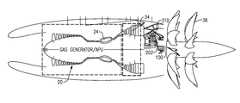
- the engine 60 as shown in FIG. 2includes a two spool core engine 120 including a low pressure compressor rotor 30 , a low pressure turbine rotor 32 , a high pressure compressor rotor 26 , and a high pressure turbine rotor 28 , and a combustor 24 as in the prior embodiments.
- This core engine 120is a so called “reverse flow” engine meaning that the compressor 30 / 26 is spaced further into the engine than is the turbine 28 / 32 .
- Air downstream of the fan rotor 62passes into a bypass duct 64 , and toward an exit 65 .
- a core inlet duct 66catches a portion of this air and turns it to the low pressure compressor 30 .
- the airis compressed in the compressor rotors 30 and 26 , combusted in combustor 24 , and products of this combustion pass downstream over the turbine rotors 28 and 32 .
- the products of combustion downstream of the turbine rotor 32pass over a fan drive turbine 74 .
- the products of combustionexit through an exit duct 76 back into the bypass duct 64 (downstream of inlet 66 such that hot gas is not re-ingested into the core inlet 66 ), and toward the exit 65 .
- a gear reduction 63may be placed between the fan drive turbine 74 and fan 62 .
- the core engine 120may have characteristics similar to those described above with regard to the core engine 20 .
- the engines 19 and 60are similar in that they have what may be called a propulsor turbine ( 34 or 74 ) which is axially downstream of the low pressure turbine rotor 32 . Further, the high pressure spool radially surrounds the low pressure spool, but neither of the spools surround the propulsor turbine, nor the shaft 100 connecting the propulsor turbine to the propellers 36 or fan 62 . In this sense, the propulsor rotor is separate from the gas generator portion of the engine.
- the disclosed engine architecturecreates a smaller core engine and yields higher overall pressure ratios and, therefore, better fuel consumption. Further, uncoupling the low pressure turbine 32 from driving a fan 62 or prop 36 enables it to run at a lower compressor surge margin, which also increases efficiency. Moreover, shaft diameters can be decreased and, in particular, for the diameter of the low pressure shafts as it is no longer necessary to drive the fan 62 or prop 36 through that shaft.
- the ratio of the low pressure compressor pressure ratio to the high pressure compressor ratiowas generally closer to 0.1 to 0.5.
- Known three spool engineshave a ratio of the low pressure compressor pressure ratio to the high pressure compressor ratio of between 0.9 and 3.0.
- a disclosed method, and a family of gas turbine enginesutilize the common gas generator or two spool core including the low pressure turbine 32 , high pressure turbine 28 , combustor 24 , high pressure compressor 26 , and low pressure compressor 30 .
- these componentscan be utilized to create any number of gas turbine engines having a distinct free or propulsor turbine driving a propulsor that may be a fan or a propeller.
- the present inventionthus, allows a dramatic reduction in the design, development, test and manufacturing cost for creating a family of gas turbine engines having different propulsor arrangements.
- the reverse core gas generatormay rotate about an axis Y, while the fan 62 may rotate about an axis X which is non-parallel to axis Y. This allows the overall length of the engine 60 to be reduced.
- an aircraft wing 200may mount the engine 60 .
- FIG. 3shows further features of the gas generator 20 which includes the propulsor turbine 34 driving a gear reduction 310 that in turn drives the shaft 100 to drive propellers 36 .
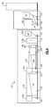
- FIG. 4shows further details of the engine 19 .
- An inlet case 220may include a bearing 221 supporting the shaft 22 at a forward end.
- An intermediate case 222may include a bearing 223 supporting the shaft 22 , and another bearing 225 supporting the shaft 21 .
- a free intershaft bearing 229may support both shafts 21 and 22 .
- a mid-turbine frame 230may be positioned downstream of the lower pressure turbine 32 , and include a bearing 231 providing an end mount for the shaft 22 .
- a turbine exhaust case 300may mount the propulsor turbine 34 .
- the turbine exhaust casemay include a plurality of bearings 301 and 302 supporting the shaft 100 .
- the propulsor turbine 34 , and propeller 36are configured as one unit, they can stay mounted to the aircraft while the gas generator 20 is removed. Due to the pressure ratio split of the gas generator 20 , the high spool is very small and lightweight, enabling the use of the intershaft bearing 229 between the high and low spool at an aft end of the gas generator 20 . Because an inner shaft bearing 231 is utilized, the mid-turbine frame 230 may be moved aft of the low pressure turbine 32 , into a cooler environment, which in turn improves cost and life.
- the front of the low pressure compressor 30includes bearing 221 , supported by the inlet case 220 , so that the low pressure compressor 30 is straddle mounted. Straddle mounting of the low pressure compressor 30 improves control over blade shift clearances and further improves engine efficiency.
- the two spool core engine or gas generator 20 / 120can be utilized generally identically to create a family of gas turbine engines having distinct free or propulsor turbines driving distinct propulsors.
- two embodiments of the family of gas turbine engines can be providedare disclosed, a worker of ordinary skill in the art would recognize any number of other arrangements that could be provided given the power of this method.
Landscapes
- Engineering & Computer Science (AREA)
- Chemical & Material Sciences (AREA)
- Combustion & Propulsion (AREA)
- Mechanical Engineering (AREA)
- General Engineering & Computer Science (AREA)
- Engine Equipment That Uses Special Cycles (AREA)
- Structures Of Non-Positive Displacement Pumps (AREA)
Abstract
Description
Claims (9)
Priority Applications (1)
| Application Number | Priority Date | Filing Date | Title |
|---|---|---|---|
| US14/647,537US9869248B2 (en) | 2012-12-17 | 2013-05-29 | Two spool gas generator to create family of gas turbine engines |
Applications Claiming Priority (3)
| Application Number | Priority Date | Filing Date | Title |
|---|---|---|---|
| US201261738020P | 2012-12-17 | 2012-12-17 | |
| US14/647,537US9869248B2 (en) | 2012-12-17 | 2013-05-29 | Two spool gas generator to create family of gas turbine engines |
| PCT/US2013/043039WO2014098962A1 (en) | 2012-12-17 | 2013-05-29 | Two spool gas generator to create family of gas turbine engines |
Publications (2)
| Publication Number | Publication Date |
|---|---|
| US20150300250A1 US20150300250A1 (en) | 2015-10-22 |
| US9869248B2true US9869248B2 (en) | 2018-01-16 |
Family
ID=50978981
Family Applications (1)
| Application Number | Title | Priority Date | Filing Date |
|---|---|---|---|
| US14/647,537Active2033-08-09US9869248B2 (en) | 2012-12-17 | 2013-05-29 | Two spool gas generator to create family of gas turbine engines |
Country Status (2)
| Country | Link |
|---|---|
| US (1) | US9869248B2 (en) |
| WO (1) | WO2014098962A1 (en) |
Cited By (4)
| Publication number | Priority date | Publication date | Assignee | Title |
|---|---|---|---|---|
| US20160290236A1 (en)* | 2015-04-03 | 2016-10-06 | Snecma | Turbo-engine including two separate ventilation flows |
| US20230121939A1 (en)* | 2021-10-19 | 2023-04-20 | Raytheon Technologies Corporation | Straddle mounted low pressure compressor |
| US12397924B2 (en) | 2024-02-02 | 2025-08-26 | Rtx Corporation | Open rotor aircraft propulsion system with bypass flowpath |
| US12404812B1 (en) | 2024-03-04 | 2025-09-02 | Rtx Corporation | Open rotor aircraft propulsion system with bypass flowpath |
Families Citing this family (3)
| Publication number | Priority date | Publication date | Assignee | Title |
|---|---|---|---|---|
| DE102014017393B4 (en)* | 2014-09-25 | 2017-08-10 | MTU Aero Engines AG | Turbomachine and process |
| US11629665B2 (en)* | 2018-09-11 | 2023-04-18 | Pratt & Whitney Canada Corp. | Gas turbine engine and method of creating classes of same |
| CN112901351B (en)* | 2019-12-03 | 2023-11-28 | 上海尚实能源科技有限公司 | Bearing support structure of birotor gas turbine engine |
Citations (20)
| Publication number | Priority date | Publication date | Assignee | Title |
|---|---|---|---|---|
| US2930190A (en)* | 1958-04-29 | 1960-03-29 | Westinghouse Electric Corp | Bypass gas turbine power plant employing regenerative cycle |
| US3308618A (en)* | 1963-12-09 | 1967-03-14 | Rolls Royce | Range blower pressure control |
| US3591313A (en)* | 1968-06-20 | 1971-07-06 | Bbc Brown Boveri & Cie | Pressure wave machine |
| US3601989A (en)* | 1969-08-29 | 1971-08-31 | Avco Corp | Marine propulsion system |
| US3808804A (en)* | 1972-02-11 | 1974-05-07 | Rolls Royce 1971 Ltd | Marine propulsion |
| US3993912A (en)* | 1974-06-10 | 1976-11-23 | General Electric Company | Marine propulsion system |
| US4123200A (en)* | 1974-02-14 | 1978-10-31 | Bbc Brown Boveri & Company Limited | Gas-dynamic pressure-wave machine |
| US4274811A (en)* | 1979-04-23 | 1981-06-23 | Ford Motor Company | Wave compressor turbocharger |
| US4338525A (en)* | 1981-01-05 | 1982-07-06 | Westinghouse Electric Corp. | Marine propulsion system |
| US4602478A (en)* | 1983-07-19 | 1986-07-29 | Rolls-Royce Limited | Marine gas turbine power transmission |
| US4719746A (en)* | 1985-07-31 | 1988-01-19 | Bbc Brown, Boveri & Company, Limited | Gas turbine with a pressure wave machine as the high pressure compressor part |
| US4796595A (en)* | 1986-02-28 | 1989-01-10 | Bbc Brown, Boveri Ltd. | Free-running pressure wave supercharger driven by gas forces |
| US5267432A (en)* | 1992-05-26 | 1993-12-07 | The United States Of America As Represented By The Administrator Of The National Aeronautics & Space Administration | System and method for cancelling expansion waves in a wave rotor |
| US5553448A (en)* | 1992-05-14 | 1996-09-10 | General Electric Company | Intercooled gas turbine engine |
| US6161374A (en) | 1999-11-01 | 2000-12-19 | Sverdlin; Anatoly | Transportation propulsion system |
| US20100327109A1 (en) | 2005-11-09 | 2010-12-30 | Pratt & Whitney Canada Corp. | Method and system for taxiing an aircraft |
| US20120034080A1 (en) | 2007-11-29 | 2012-02-09 | Agrawal Rajendra K | Actuation mechanism for a convertible gas turbine propulsion system |
| US20120079808A1 (en) | 2010-09-30 | 2012-04-05 | Christopher Charles Glynn | Hydraulic system for fan pitch change actuation of counter-rotating propellers |
| US20120304619A1 (en) | 2010-02-16 | 2012-12-06 | Michael Alan Beachy Head | Engine for thrust or shaft output and corresponding operating method |
| US8995620B2 (en)* | 2012-07-06 | 2015-03-31 | Moxtek, Inc. | Inductor switching LC power circuit |
- 2013
- 2013-05-29USUS14/647,537patent/US9869248B2/enactiveActive
- 2013-05-29WOPCT/US2013/043039patent/WO2014098962A1/enactiveApplication Filing
Patent Citations (20)
| Publication number | Priority date | Publication date | Assignee | Title |
|---|---|---|---|---|
| US2930190A (en)* | 1958-04-29 | 1960-03-29 | Westinghouse Electric Corp | Bypass gas turbine power plant employing regenerative cycle |
| US3308618A (en)* | 1963-12-09 | 1967-03-14 | Rolls Royce | Range blower pressure control |
| US3591313A (en)* | 1968-06-20 | 1971-07-06 | Bbc Brown Boveri & Cie | Pressure wave machine |
| US3601989A (en)* | 1969-08-29 | 1971-08-31 | Avco Corp | Marine propulsion system |
| US3808804A (en)* | 1972-02-11 | 1974-05-07 | Rolls Royce 1971 Ltd | Marine propulsion |
| US4123200A (en)* | 1974-02-14 | 1978-10-31 | Bbc Brown Boveri & Company Limited | Gas-dynamic pressure-wave machine |
| US3993912A (en)* | 1974-06-10 | 1976-11-23 | General Electric Company | Marine propulsion system |
| US4274811A (en)* | 1979-04-23 | 1981-06-23 | Ford Motor Company | Wave compressor turbocharger |
| US4338525A (en)* | 1981-01-05 | 1982-07-06 | Westinghouse Electric Corp. | Marine propulsion system |
| US4602478A (en)* | 1983-07-19 | 1986-07-29 | Rolls-Royce Limited | Marine gas turbine power transmission |
| US4719746A (en)* | 1985-07-31 | 1988-01-19 | Bbc Brown, Boveri & Company, Limited | Gas turbine with a pressure wave machine as the high pressure compressor part |
| US4796595A (en)* | 1986-02-28 | 1989-01-10 | Bbc Brown, Boveri Ltd. | Free-running pressure wave supercharger driven by gas forces |
| US5553448A (en)* | 1992-05-14 | 1996-09-10 | General Electric Company | Intercooled gas turbine engine |
| US5267432A (en)* | 1992-05-26 | 1993-12-07 | The United States Of America As Represented By The Administrator Of The National Aeronautics & Space Administration | System and method for cancelling expansion waves in a wave rotor |
| US6161374A (en) | 1999-11-01 | 2000-12-19 | Sverdlin; Anatoly | Transportation propulsion system |
| US20100327109A1 (en) | 2005-11-09 | 2010-12-30 | Pratt & Whitney Canada Corp. | Method and system for taxiing an aircraft |
| US20120034080A1 (en) | 2007-11-29 | 2012-02-09 | Agrawal Rajendra K | Actuation mechanism for a convertible gas turbine propulsion system |
| US20120304619A1 (en) | 2010-02-16 | 2012-12-06 | Michael Alan Beachy Head | Engine for thrust or shaft output and corresponding operating method |
| US20120079808A1 (en) | 2010-09-30 | 2012-04-05 | Christopher Charles Glynn | Hydraulic system for fan pitch change actuation of counter-rotating propellers |
| US8995620B2 (en)* | 2012-07-06 | 2015-03-31 | Moxtek, Inc. | Inductor switching LC power circuit |
Non-Patent Citations (2)
| Title |
|---|
| International Preliminary Report on Patentability for International Application No. PCT/US2013/043039 dated Jul. 2, 2015. |
| International Search Report from PCT/US2013/043039. |
Cited By (5)
| Publication number | Priority date | Publication date | Assignee | Title |
|---|---|---|---|---|
| US20160290236A1 (en)* | 2015-04-03 | 2016-10-06 | Snecma | Turbo-engine including two separate ventilation flows |
| US10557415B2 (en)* | 2015-04-03 | 2020-02-11 | Safran Aircraft Engines | Turbo-engine including two separate ventilation flows |
| US20230121939A1 (en)* | 2021-10-19 | 2023-04-20 | Raytheon Technologies Corporation | Straddle mounted low pressure compressor |
| US12397924B2 (en) | 2024-02-02 | 2025-08-26 | Rtx Corporation | Open rotor aircraft propulsion system with bypass flowpath |
| US12404812B1 (en) | 2024-03-04 | 2025-09-02 | Rtx Corporation | Open rotor aircraft propulsion system with bypass flowpath |
Also Published As
| Publication number | Publication date |
|---|---|
| WO2014098962A1 (en) | 2014-06-26 |
| US20150300250A1 (en) | 2015-10-22 |
Similar Documents
| Publication | Publication Date | Title |
|---|---|---|
| US11585354B2 (en) | Engine having variable pitch outlet guide vanes | |
| US9890704B2 (en) | Compressor system | |
| CN104081024B (en) | Gas-turbine unit and turbine | |
| EP3101258B1 (en) | Geared architecture for a gas turbine engine and a corresponding method | |
| US11608786B2 (en) | Gas turbine engine with power density range | |
| US9869248B2 (en) | Two spool gas generator to create family of gas turbine engines | |
| EP3058202A2 (en) | Geared turbofan engine with targeted modular efficiency | |
| US9879694B2 (en) | Turbo-compressor with geared turbofan | |
| US20140150440A1 (en) | Gas turbine engine with a low speed spool driven pump arrangement | |
| US9850821B2 (en) | Gas turbine engine with fan-tied inducer section | |
| US9739205B2 (en) | Geared turbofan with a gearbox upstream of a fan drive turbine | |
| US20130318999A1 (en) | Gas turbine engine with a counter rotating fan | |
| US20190153959A1 (en) | Gas turbine engine geared architecture | |
| US20150315974A1 (en) | Two spool gas generator with improved pressure split | |
| EP3112649A1 (en) | Gas turbine engine with fan-tied inducer section | |
| US20150176484A1 (en) | Geared turbofan with a gearbox aft of a fan drive turbine | |
| JP2016128693A (en) | Gas turbine engine | |
| WO2013130187A1 (en) | Geared turbofan engine with counter-rotating shafts |
Legal Events
| Date | Code | Title | Description |
|---|---|---|---|
| AS | Assignment | Owner name:UNITED TECHNOLOGIES CORPORATION, CONNECTICUT Free format text:ASSIGNMENT OF ASSIGNORS INTEREST;ASSIGNORS:SUCIU, GABRIEL L.;MERRY, BRIAN D.;REEL/FRAME:035720/0356 Effective date:20130529 | |
| STCF | Information on status: patent grant | Free format text:PATENTED CASE | |
| AS | Assignment | Owner name:RAYTHEON TECHNOLOGIES CORPORATION, MASSACHUSETTS Free format text:CHANGE OF NAME;ASSIGNOR:UNITED TECHNOLOGIES CORPORATION;REEL/FRAME:054062/0001 Effective date:20200403 | |
| AS | Assignment | Owner name:RAYTHEON TECHNOLOGIES CORPORATION, CONNECTICUT Free format text:CORRECTIVE ASSIGNMENT TO CORRECT THE AND REMOVE PATENT APPLICATION NUMBER 11886281 AND ADD PATENT APPLICATION NUMBER 14846874. TO CORRECT THE RECEIVING PARTY ADDRESS PREVIOUSLY RECORDED AT REEL: 054062 FRAME: 0001. ASSIGNOR(S) HEREBY CONFIRMS THE CHANGE OF ADDRESS;ASSIGNOR:UNITED TECHNOLOGIES CORPORATION;REEL/FRAME:055659/0001 Effective date:20200403 | |
| MAFP | Maintenance fee payment | Free format text:PAYMENT OF MAINTENANCE FEE, 4TH YEAR, LARGE ENTITY (ORIGINAL EVENT CODE: M1551); ENTITY STATUS OF PATENT OWNER: LARGE ENTITY Year of fee payment:4 | |
| AS | Assignment | Owner name:RTX CORPORATION, CONNECTICUT Free format text:CHANGE OF NAME;ASSIGNOR:RAYTHEON TECHNOLOGIES CORPORATION;REEL/FRAME:064714/0001 Effective date:20230714 | |
| MAFP | Maintenance fee payment | Free format text:PAYMENT OF MAINTENANCE FEE, 8TH YEAR, LARGE ENTITY (ORIGINAL EVENT CODE: M1552); ENTITY STATUS OF PATENT OWNER: LARGE ENTITY Year of fee payment:8 |