US9867985B2 - Systems and apparatus for gait modulation and methods of use - Google Patents
Systems and apparatus for gait modulation and methods of useDownload PDFInfo
- Publication number
- US9867985B2 US9867985B2US14/223,340US201414223340AUS9867985B2US 9867985 B2US9867985 B2US 9867985B2US 201414223340 AUS201414223340 AUS 201414223340AUS 9867985 B2US9867985 B2US 9867985B2
- Authority
- US
- United States
- Prior art keywords
- signal
- sensor
- time
- electric stimulator
- limb
- Prior art date
- Legal status (The legal status is an assumption and is not a legal conclusion. Google has not performed a legal analysis and makes no representation as to the accuracy of the status listed.)
- Active
Links
Images


Classifications
- A—HUMAN NECESSITIES
- A61—MEDICAL OR VETERINARY SCIENCE; HYGIENE
- A61N—ELECTROTHERAPY; MAGNETOTHERAPY; RADIATION THERAPY; ULTRASOUND THERAPY
- A61N1/00—Electrotherapy; Circuits therefor
- A61N1/18—Applying electric currents by contact electrodes
- A61N1/32—Applying electric currents by contact electrodes alternating or intermittent currents
- A61N1/36—Applying electric currents by contact electrodes alternating or intermittent currents for stimulation
- A61N1/36003—Applying electric currents by contact electrodes alternating or intermittent currents for stimulation of motor muscles, e.g. for walking assistance
- A—HUMAN NECESSITIES
- A61—MEDICAL OR VETERINARY SCIENCE; HYGIENE
- A61B—DIAGNOSIS; SURGERY; IDENTIFICATION
- A61B5/00—Measuring for diagnostic purposes; Identification of persons
- A61B5/103—Measuring devices for testing the shape, pattern, colour, size or movement of the body or parts thereof, for diagnostic purposes
- A61B5/11—Measuring movement of the entire body or parts thereof, e.g. head or hand tremor or mobility of a limb
- A61B5/112—Gait analysis
- A—HUMAN NECESSITIES
- A61—MEDICAL OR VETERINARY SCIENCE; HYGIENE
- A61B—DIAGNOSIS; SURGERY; IDENTIFICATION
- A61B5/00—Measuring for diagnostic purposes; Identification of persons
- A61B5/48—Other medical applications
- A61B5/4836—Diagnosis combined with treatment in closed-loop systems or methods
- A—HUMAN NECESSITIES
- A61—MEDICAL OR VETERINARY SCIENCE; HYGIENE
- A61B—DIAGNOSIS; SURGERY; IDENTIFICATION
- A61B5/00—Measuring for diagnostic purposes; Identification of persons
- A61B5/48—Other medical applications
- A61B5/4851—Prosthesis assessment or monitoring
- A—HUMAN NECESSITIES
- A61—MEDICAL OR VETERINARY SCIENCE; HYGIENE
- A61B—DIAGNOSIS; SURGERY; IDENTIFICATION
- A61B5/00—Measuring for diagnostic purposes; Identification of persons
- A61B5/68—Arrangements of detecting, measuring or recording means, e.g. sensors, in relation to patient
- A61B5/6801—Arrangements of detecting, measuring or recording means, e.g. sensors, in relation to patient specially adapted to be attached to or worn on the body surface
- A61B5/6802—Sensor mounted on worn items
- A61B5/6811—External prosthesis
- A—HUMAN NECESSITIES
- A61—MEDICAL OR VETERINARY SCIENCE; HYGIENE
- A61B—DIAGNOSIS; SURGERY; IDENTIFICATION
- A61B5/00—Measuring for diagnostic purposes; Identification of persons
- A61B5/103—Measuring devices for testing the shape, pattern, colour, size or movement of the body or parts thereof, for diagnostic purposes
- A61B5/1036—Measuring load distribution, e.g. podologic studies
- A61B5/1038—Measuring plantar pressure during gait
- A—HUMAN NECESSITIES
- A61—MEDICAL OR VETERINARY SCIENCE; HYGIENE
- A61B—DIAGNOSIS; SURGERY; IDENTIFICATION
- A61B5/00—Measuring for diagnostic purposes; Identification of persons
- A61B5/68—Arrangements of detecting, measuring or recording means, e.g. sensors, in relation to patient
- A61B5/6801—Arrangements of detecting, measuring or recording means, e.g. sensors, in relation to patient specially adapted to be attached to or worn on the body surface
- A61B5/6802—Sensor mounted on worn items
- A61B5/6804—Garments; Clothes
- A61B5/6807—Footwear
- A—HUMAN NECESSITIES
- A61—MEDICAL OR VETERINARY SCIENCE; HYGIENE
- A61B—DIAGNOSIS; SURGERY; IDENTIFICATION
- A61B5/00—Measuring for diagnostic purposes; Identification of persons
- A61B5/68—Arrangements of detecting, measuring or recording means, e.g. sensors, in relation to patient
- A61B5/6801—Arrangements of detecting, measuring or recording means, e.g. sensors, in relation to patient specially adapted to be attached to or worn on the body surface
- A61B5/6813—Specially adapted to be attached to a specific body part
- A61B5/6828—Leg
- A—HUMAN NECESSITIES
- A61—MEDICAL OR VETERINARY SCIENCE; HYGIENE
- A61F—FILTERS IMPLANTABLE INTO BLOOD VESSELS; PROSTHESES; DEVICES PROVIDING PATENCY TO, OR PREVENTING COLLAPSING OF, TUBULAR STRUCTURES OF THE BODY, e.g. STENTS; ORTHOPAEDIC, NURSING OR CONTRACEPTIVE DEVICES; FOMENTATION; TREATMENT OR PROTECTION OF EYES OR EARS; BANDAGES, DRESSINGS OR ABSORBENT PADS; FIRST-AID KITS
- A61F5/00—Orthopaedic methods or devices for non-surgical treatment of bones or joints; Nursing devices ; Anti-rape devices
- A61F5/01—Orthopaedic devices, e.g. long-term immobilising or pressure directing devices for treating broken or deformed bones such as splints, casts or braces
- A—HUMAN NECESSITIES
- A61—MEDICAL OR VETERINARY SCIENCE; HYGIENE
- A61N—ELECTROTHERAPY; MAGNETOTHERAPY; RADIATION THERAPY; ULTRASOUND THERAPY
- A61N1/00—Electrotherapy; Circuits therefor
- A61N1/02—Details
- A61N1/04—Electrodes
- A61N1/0404—Electrodes for external use
- A61N1/0408—Use-related aspects
- A61N1/0452—Specially adapted for transcutaneous muscle stimulation [TMS]
- A—HUMAN NECESSITIES
- A61—MEDICAL OR VETERINARY SCIENCE; HYGIENE
- A61N—ELECTROTHERAPY; MAGNETOTHERAPY; RADIATION THERAPY; ULTRASOUND THERAPY
- A61N1/00—Electrotherapy; Circuits therefor
- A61N1/02—Details
- A61N1/04—Electrodes
- A61N1/0404—Electrodes for external use
- A61N1/0472—Structure-related aspects
- A61N1/0484—Garment electrodes worn by the patient
Definitions
- the embodiments described hereinrelate generally to gait modulation systems, and more particularly, to a functional electrical stimulation (FES) orthosis for gait modulation and methods of using the same.
- FESfunctional electrical stimulation
- Gaitthe biomechanical description of walking, can suffer static and dynamic parameter variations due to neuromuscular impairments, which cause non-symmetrical walking, reduced walking speed, and reduced walking stability.
- drop footdescribes a gait attributable to weak or uncoordinated activation of the ankle dorsiflexors due to disease or trauma to the central nervous system.
- Limb musclescan generally be activated with functional electrical stimulation (FES).
- FESfunctional electrical stimulation
- precisely timed bursts of short electrical pulsese.g., from a neuroprosthetic, an FES orthosis, and/or the like
- FESfunctional electrical stimulation
- a neuroprosthetice.g., an FES orthosis, and/or the like
- motor nervese.g., from a neuroprosthetic, an FES orthosis, and/or the like
- drawbacksthat prevent the systems from being widely used by potential patients. For example, in instances in which stroke or brain injury results in problems with arm movement or gait, such problems are often accompanied by hand impairment on the same side of the body as the problematic limb.
- donning an FES orthosisis often carried out using solely the contra-lateral, unaffected hand.
- the posture of the plegic limbis often problematic, especially in cases where spasticity results in reduced voluntary movements and/or limited passive range of motion of the limb joints. Consequently, objective biomechanical problems exist in donning some known orthotic devices as well as locating the electrodes in exact positions onto the limb, which is essential for activating the desired movement pattern. As such, some known neuroprosthetic devices fail to enable facile, quick, and accurate donning of the device by an impaired patient using a single hand, and particularly, when the least effected hand is shaky or otherwise unstable.
- FES devicestypically utilize a stimulator unit to create and control the electrical pulses being applied to motor nerves that is physically separate from the FES orthosis.
- the external stimulator unitwhich is connected to the FES orthosis by several electrical wires, is located on the body of the user and/or is otherwise worn by the user. These devices can be inconvenient for the user. Specifically, the wiring, which is usually arranged to run along the leg under the clothing to connect the device components, can be difficult to operate, cumbersome and uncomfortable.
- an FES orthosiscan be a self-contained device.
- some known orthosescan include a stimulator unit coupled to a narrow band that is made of a thermoplastic material, which is molded to the limb anatomy of an individual user by heating and softening the thermoplastic material and subsequently fitting the band to the contour of the underlying limb segment.
- the shape and size of the device and the electrode positioningis custom-fitted to the leg of one user and individualized for the user. This procedure is carried out by a medical professional trained, for example, to accurately identify the stimulation points that cause contraction of the muscles, positioning and locking the electrodes thereto.
- Activation of the leg muscles by electrical stimulationtypically includes transferring high stimulation currents through one or more electrodes to the skin surface of the patient, which activates skin sensory receptors in addition to underlying excitable motor nerve and muscle tissue.
- the intensity of sensory activationoften depends on the intensity of the current density passing through the skin surface.
- the level of muscle activationtherefore, is often limited to the patient's individual tolerance to activation of such skin pain sensors.
- the stimulation parameters of the deviceare adjusted for each patient, which can be time consuming and often includes attaching the orthosis to a control device via wires.
- an apparatusincludes a frame assembly, a sensor, and an electric stimulator.
- the frameis configured to be removably coupled to a portion of a limb such that the portion of the limb is substantially enveloped by the frame.
- the sensoris operably coupled to the frame and is configured to produce a first signal associated with a gait characteristic at a first time, and a second signal associated with the gait characteristic at a second time, after the first time.
- the first time and the second timedefine a time period therebetween.
- the electric stimulatoris removably coupled to the frame and is in electrical communication with the sensor and an electrode assembly.
- the electrode assemblyis in electrical communication with a portion of a neuromuscular system of the limb when the frame is coupled thereto and is configured to receive the first signal from the sensor substantially at the first time and the second signal from the sensor substantially at the second time. Based at least in part on the gait characteristic at the first time, the electric stimulator is configured to send a third signal to the electrode assembly substantially at the first time operable to cause the electrode assembly to provide an electric stimulation to the portion of the neuromuscular system of the limb substantially during the time period.
- FIG. 1is a schematic illustration of a system for gait modulation according to an embodiment.
- FIG. 2is a perspective view of a functional electrical stimulation (FES) orthosis for gait modulation according to an embodiment.
- FESfunctional electrical stimulation
- FIG. 3is a perspective view of a portion of the FES orthosis of FIG. 2 illustrating a coupling an electric stimulator to a frame.
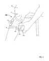
- FIG. 4illustrates a portion of a patient donning of the FES orthosis of FIG. 2 on an impaired leg.
- FIG. 5is a schematic side view of a portion of the FES orthosis of FIG. 2 illustrating an electrical connection between the electric stimulator of FIG. 3 and an electrode assembly.
- FIG. 6is a rear perspective view of the FES orthosis of FIG. 2 illustrating the electrode assembly of FIG. 5 coupled to an inner surface of the frame of FIGS. 3-5 .
- FIG. 7is a schematic block diagram illustrating an electrical system of the FES orthosis of FIG. 2 .
- FIG. 8illustrates the FES orthosis of FIG. 2 included in a system for gait modulation.
- FIG. 9is a flowchart illustrating a method of using an FES orthosis for gait modulation according to an embodiment.
- FIG. 10is a flowchart illustrating a method of using an FES system for gait modulation according to an embodiment.
- an apparatusincludes a frame assembly, a sensor, and an electric stimulator.
- the frameis configured to be removably coupled to a portion of a limb such that the portion of the limb is substantially enveloped by the frame.
- the sensoris operably coupled to the frame and is configured to produce at least a first signal associated with a gait characteristic at a first time, and a second signal associated with the gait characteristic at a second time, after the first time.
- the first time and the second timedefine a time period therebetween.
- the electric stimulatoris removably coupled to the frame and is in electrical communication with the sensor and an electrode assembly.
- the electrode assemblyis in electrical communication with a portion of a neuromuscular system of the limb when the frame is coupled thereto and is configured to receive the first signal from the sensor substantially at the first time and the second signal from the sensor substantially at the second time.
- the electric stimulatoris configured to send a third signal to the electrode assembly substantially at the first time operable to cause the electrode assembly to provide an electric stimulation to the portion of the neuromuscular system of the limb substantially during the time period.
- a methodincludes receiving, at an electric stimulator and from a sensor, a first signal associated with a gait characteristic. Based at least in part on the first signal associated with the gait characteristic, one or more system parameters is calculated. A signal is sent, based at least in part on the one or more system parameters, from the electric stimulator to an electrode assembly to cause the electrode assembly to provide an electric stimulation to a portion of a neuromuscular system of a limb. A second signal associated with the gait characteristic is received at the electric stimulator from the sensor. The method includes terminating the electric stimulation of the portion of the neuromuscular system of the limb based on receiving the second signal associated with the gait characteristic.
- a method of using an electric stimulator having a sensor and an electrode assembly in electrical communication with a portion of a neuromuscular system of a limbincludes receiving, at the electric stimulator, a first signal that is sent from a control device via a first communication channel associated with a wireless communication over a network.
- the first signalis associated with a system parameter.
- a second signalis sent from the electric stimulator to the control device via the first communication channel.
- the second signalis associated with a confirmation of the system parameter.
- the electric stimulatorreceives a third signal that is sent from the sensor via a second communication channel, different from the first communication channel.
- the third signalis associated with a gait characteristic.
- the methodincludes sending, from the electric stimulator to the electrode assembly, a fourth signal.
- the fourth signalis operable to cause the electrode assembly to provide an electric stimulation to the portion of the neuromuscular system of the limb based at least in part on the system parameter and the gait characteristic.
- a memberis intended to mean a single member or a combination of members
- a materialis intended to mean one or more materials, or a combination thereof.
- limb segmentrefers to at least a portion of a mammalian appendage.
- the embodiments described hereincan be coupled to and/or otherwise placed in contact with a limb segment that can include a portion of the upper and/or lower arm, or a portion of the upper and/or lower leg of a human body.
- envelopeAs used herein, the terms “envelop,” “enveloping,” and/or the like, with regard to a limb segment and an article or device coupled thereto, refer to an article or device that substantially surrounds and/or covers at least one half the circumference of a limb segment when coupled thereto. For example, if when coupled to a limb segment, an article or device substantially circumscribes a portion of the limb segment, the article or device can be said to envelop the portion of the limb segment.
- FES orthosisAs used herein, the terms “FES orthosis,” “orthosis,” “neuroprosthetic,” “FES device,” “device,” and/or the like can be used interchangeably and refer generally to a medical apparatus that is selectively placed in contact with a portion of a patient. As described herein, such devices can include one or more electrodes that can transmit a flow of electrical current to a portion of a neuromuscular system associated with the portion of the patient, thereby providing functional electrical stimulation to, for example, an impaired limb.
- reversiblewhen used to described a process and/or procedure generally refer to a non-destructive process or procedure that can be subsequently undone by a similar yet substantially opposed, inverse, and/or opposite non-destructive process or procedure.
- a reversible attachmentrefers to a non-destructive, repeatable attachment and/or detachment of the element or assembly.
- the term “set”can refer to multiple features or a singular feature with multiple parts.
- the set of wallscan be considered as one wall with multiple portions, or the set of walls can be considered as multiple, distinct walls.
- a monolithically constructed itemcan include a set of walls.
- Such a set of wallsmay include multiple portions that are either continuous or discontinuous from each other.
- a set of wallscan also be fabricated from multiple items that are produced separately and are later joined together (e.g., via a weld, an adhesive, or any suitable method).
- the terms “about” and “approximately”generally mean plus or minus 10% of the value stated, unless the context clearly expresses otherwise. For example, about 0.5 would include 0.45 and 0.55, about 10 would include 9 to 11, about 1000 would include 900 to 1100. In some instances, such as when assessing a gait phase of a stimulation parameter and/or the like, the terms about and approximately can generally mean greater than plus or minus 10% of the value stated.
- the terms “communication channel,” “communication mode,” and/or “modality”can be used interchangeably and refer generally to one or more modes of communication using, for example, one or more electronic devices. Such modes of communication can be associated with a specific format (e.g., a data unit format) that, in some instances, can be unique to that mode of communication (e.g., a different protocol, a different data unit structure or arrangement, etc.).
- a specific formate.g., a data unit format
- a cellular telephonee.g., a smart phone
- SMSshort message service
- MMSmultimedia message service
- WiFi®wireless fidelity
- the channel and/or modalityincludes, defines, and/or otherwise is associated with a data unit format suitable for transmission of data via that communication mode.
- modulerefers to any assembly and/or set of operatively-coupled electrical components that can include, for example, a memory, a processor, electrical traces, optical connectors, software (executing in hardware), and/or the like.
- a module executed in the processorcan be any combination of hardware-based modules (e.g., a field-programmable gate array (FPGA), an application specific integrated circuit (ASIC), a digital signal processor (DSP)) and/or software-based modules (e.g., a module of computer code stored in memory and/or executed at the processor) capable of performing one or more specific functions associated with that module.
- FPGAfield-programmable gate array
- ASICapplication specific integrated circuit
- DSPdigital signal processor
- FIG. 1is a schematic illustration of a system 100 used for gait modulation according to an embodiment.
- the system 100can be used by a human patient who has one or more impaired limbs as a result of injury and/or disease (e.g., stroke, spinal cord injury, head injury, cerebral palsy, multiple sclerosis, etc.).
- the system 100includes a functional electrical stimulation (FES) orthosis 105 (also referred to herein as “orthosis” and/or “device”) that is placed in physical and electrical contact with a limb 10 of the patient such as, for example, a lower limb segment of an impaired leg.
- FESfunctional electrical stimulation
- the patient and/or a health care professionalcan engage the system 100 in such a manner as to cause the orthosis 105 to selectively provide electrical stimulation to a portion of a neuromuscular system of the limb 10 , which can, in turn, facilitate gait of the patient who might otherwise experience, for example, drop foot or the like, as described in further detail herein.
- the orthosis 105includes a frame 110 , an electrode assembly 120 , one or more sensors 130 , and an electrical stimulator 140 .
- at least a portion of the orthosis 105can be substantially similar in form and function as those described in U.S. Pat. No. 7,899,556 entitled, “Gait Modulation System and Method,” filed Apr. 27, 2006 (referred to henceforth as the “'556 patent”), U.S. Pat. No. 8,209,036 entitled, “Gait Modulation System and Method,” filed Nov. 12, 2006 (referred to henceforth as the “'036 patent”), and U.S. patent application Ser. No. 13/532,597 entitled, “Gait Modulation System and Method,” filed Jun. 25, 2012 (referred to henceforth as the “'597 application”), the disclosures of which are incorporated herein by reference in their entireties.
- At least a portion of the frame 110can be formed from a semi-rigid material such as, for example, a relatively thin metal, a thermoplastic, a polymer, and/or the like, which can enable the frame 110 to provide structural support for the orthosis 105 .
- the frame 110can have any suitable shape and/or size that can be, for example, associated with a segment of the limb 10 (e.g., a lower segment of a patient's leg).
- at least a portion of the frame 110can be transitioned between a first configuration and a second configuration to couple the frame 110 to the limb 10 .
- the frame 110can include a coupling portion or the like that can be transitioned between a first (e.g., open) configuration and a second (e.g., closed) configuration to at least temporarily couple the frame 110 to the limb 10 .
- a coupling portion or the likecan be transitioned between a first (e.g., open) configuration and a second (e.g., closed) configuration to at least temporarily couple the frame 110 to the limb 10 .
- the frame 110can be configured to substantially envelop and/or circumscribe the limb 10 .
- the coupling portioncan be one or more straps, clips, ratchets, and/or the like that can allow for facile placement and coupling to the frame 110 to the limb 10 , as described in further detail herein.
- the electrode assembly 120 of the orthosis 105is coupled to an inner surface of the frame 110 .
- the electrode assembly 120can be any suitable arrangement of hardware and/or software.
- the electrode assembly 120can include one or more electrodes that are each electrically coupled to a wire, electrical trace, and/or the like that are operable in electrically coupling the one or more electrodes to the electric stimulator 140 .
- the electrode assembly 120can be disposed within a portion of the frame 110 .
- the electrode assemblycan include a set of wires that are substantially enclosed by a portion of the frame 110 .
- the wirescan include end portions that each include a connector or the like that can, for example, be electrically coupled to the electric stimulator 140 at a first end portion and that can, for example, be electrically coupled to the electrodes at a second end portion.
- the electrode assembly 120can be substantially similar in form and function as those described in the '556 patent, the '036 patent, and/or the '597 application.
- the sensor 130 of the orthosis 105can be any suitable sensor device or can include a combination of sensor devices.
- the sensor 130can include a tilt sensor, an accelerometer, a gyroscope, a pressure sensor, a speedometer, and/or the like.
- the sensor 130can be configured to sense and/or otherwise detect a characteristic associated with, for example, a gait event such as position of the sensor 130 relative to the orthosis 105 , position of the limb 10 relative to a reference plane or the like, angular position of the limb 10 relative to a reference plane or the like, velocity, rate of change in velocity (i.e., acceleration), tilt of the patient's foot, pressure (e.g., when the foot and/or shoe contacts a surface upon which the patient is walking), etc.
- a gait eventsuch as position of the sensor 130 relative to the orthosis 105 , position of the limb 10 relative to a reference plane or the like, angular position of the limb 10 relative to a reference plane or the like, velocity, rate of change in velocity (i.e., acceleration), tilt of the patient's foot, pressure (e.g., when the foot and/or shoe contacts a surface upon which the patient is walking), etc.
- the senor 130can be included in and/or integrated with the frame 110 , the electrode assembly 120 , and/or the electric stimulator 140 .
- the sensor 130can be physically distinct from the orthosis 105 and in electrical communication with the electric stimulator 140 via a wireless communication channel.
- the electric stimulator 140can be coupled to the frame 110 , which in turn, is coupled to a first segment of the limb (e.g., adjacent to the knee of the patient's leg) and the sensor 130 can be coupled to and/or otherwise can be associated with a second segment of the limb 10 (e.g., adjacent to the foot and/or ankle of the patient's impaired leg).
- the senor 130can be coupled and/or otherwise can be associated with a segment of the contralateral leg (e.g., adjacent to the foot and/or ankle of the patient's leg not donning the electric stimulator 140 ).
- the system 100can include multiple distinct sensors 130 .
- the system 100can include a first sensor that is integrated with the electric stimulator 140 and a second sensor that is physically distinct from, yet in electrical communication with, the electric stimulator 140 (e.g., disposed within and/or coupled to a shoe of the patient).
- the electrical stimulator 140can be configured to receive signals from and/or send signals to the first sensor via a first communication channel, associated with a wired signal transmission (e.g., signals transmitted along a wire or signal trace), and a second communication channel, associated with a wireless signal transmission (e.g., WiFi®, Bluetooth®, etc.), as described in further detail herein.
- a wired signal transmissione.g., signals transmitted along a wire or signal trace
- a wireless signal transmissione.g., WiFi®, Bluetooth®, etc.
- the electric stimulator 140 of the orthosis 105can be any suitable functional electrical stimulation device having any combination of hardware and software.
- the electric stimulator 140can be an electronic device that can include one or more electrical circuits operable in providing a flow of electrical current to at least a portion of the neuromuscular system of the limb 10 .
- the electric stimulator 140 of the orthosis 105is removably coupled to the frame 110 .
- the frame 110can form a cradle and/or the like that can be configured to at least temporarily retain the electrical stimulator 140 therein, as described below with respect to specific embodiments.
- the electric stimulator 140is configured to be placed in electrical communication with the electrode assembly 120 and the sensor 130 .
- the electrode assembly 120 and/or the sensor 130can be included in (e.g., integrated with) the electric stimulator 140 .
- the electrode assembly 120 and the sensor 130can be operably coupled to the electric stimulator 140 via any suitable wiring, connector, interface, and/or structure.
- the frame 110can include a connector and/or the like configured to place the electric stimulator 140 in electrical communication with, for example, the electrode assembly 120 and/or the sensor 130 .
- the electric stimulator 140can receive and/or send signals to a set of external and/or implanted electrical devices via any suitable communication mode.
- the electric stimulator 140can include two, three, four, five, six, or more communication and/or electrical channels that can be operable in sending and/or receiving signals to and/or from, respectively, the electrode assembly 120 , the sensor 130 , and/or any other suitable electronic device operably coupled thereto.
- At least a portion of the communication and/or electrical channelscan be associated with sending and/or receiving signal via a wireless communication modality (e.g., a modality, format, and/or the like associated with WiFi®, Bluetooth®, near field communication (NFC), cellular communication such as, short message service (SMS) or multimedia message service (MMS), and/or the like), as described in further detail herein.
- a wireless communication modalitye.g., a modality, format, and/or the like associated with WiFi®, Bluetooth®, near field communication (NFC), cellular communication such as, short message service (SMS) or multimedia message service (MMS), and/or the like
- SMSshort message service
- MMSmultimedia message service
- the system 100can be used for gait modulation of patients with an impaired limb. More specifically, the system 100 can be used to enhance the limb function of a patient experiencing drop foot.
- the patientcan manipulate the orthosis 105 in such a manner as to couple the orthosis 105 to the impaired limb. For example, the patient can position the orthosis 105 adjacent to the knee of an impaired leg and can transition the frame 110 from a first configuration to a second configuration (as described above) to removably couple the orthosis 105 to the leg.
- the placement of the orthosis 105can be such that a set of electrodes included in the electrode assembly 120 are disposed in a location relative to the leg that is associated and/or corresponds to a desired portion of the neuromuscular system of the leg. More specifically, to enhance the leg function of a patient experiencing drop foot during gait, the orthosis 105 can be positioned relative to the leg to place the electrodes in electric communication with the peroneal nerve and/or the tibial nerve.
- the electrodescan transmit functional electrical stimulation to the peroneal nerve, which can result in dorsiflexion of the foot, and/or the tibial nerve, which can result in plantarflexion of the foot, thereby enhancing the function of the impaired leg to mitigate the effects of drop foot, as described in further detail herein.
- the patientcan begin walking.
- the sensor 130can be configured to sense and/or detect a set of characteristics (such as those described above) associated with a gait event and can send a signal associated with the characteristic to the electric stimulator 140 .
- the gait eventcan be associated with a “heel-off” event (i.e., the point during gait at which the heel is lifted off the surface upon which the patient is walking).
- the sensor 130can send the signal to the electric stimulator 140 via any suitable communication channel.
- the sensor 130can send the signal via a communication channel associated with a wired signal transmission. If, however, the sensor 130 is physically distinct from the other portions of the orthosis 105 , the sensor can send the signal via a communication channel associated with a wireless signal transmission, such as those described above.
- the electric stimulator 140can receive a signal from multiple sensors 130 that can be configured to sense and/or detect a characteristic associated with a gait event at different segments along the leg of the patient.
- the electric stimulator 140can be configured to transmit an electrical current resulting from a relatively high voltage (e.g., generated by a power supply or the like included in the electric stimulator 140 ) along an electric circuit that is electrically coupled to the electrode assembly 120 .
- a relatively high voltagee.g., generated by a power supply or the like included in the electric stimulator 140
- the current resulting from the relatively high voltage(also referred to herein as “high current”) is transmitted to the electrodes of the electrode assembly 120 , which in turn, provide FES to the peroneal nerve, thereby resulting in dorsiflexion and/or plantarflexion of the foot substantially at the time of the heel-off event (e.g., a very short time after the sensor 130 detects the heel-off event consistent with a rate of electrical signal and/or electrical current transmission such as, 0.10 seconds, 0.05 seconds, 0.01 seconds, 0.001 seconds, 0.0001 seconds, or less).
- a rate of electrical signal and/or electrical current transmissionsuch as, 0.10 seconds, 0.05 seconds, 0.01 seconds, 0.001 seconds, 0.0001 seconds, or less.
- the sensor 130can sense and/or detect a characteristic associated with a second gait event such as, for example, a “heel-on” event (i.e., the point during gait at which the heel is placed in contact with the surface of upon which the patient is walking).
- a characteristic associated with a second gait eventsuch as, for example, a “heel-on” event (i.e., the point during gait at which the heel is placed in contact with the surface of upon which the patient is walking).
- the sensor 130can send a signal associated with the characteristic to the electric stimulator 140 and, upon receipt, the electric stimulator 140 can terminate the flow of the relatively high current to the electrodes in electrical contact with the peroneal nerve.
- the electric stimulator 140can generate a relatively high current along an electric circuit that is electrically coupled to one or more electrodes in electrical communication with the tibial nerve.
- the electrodescan provide FES to the tibial nerve resulting in plantarflexion of the foot substantially at the time of the heel-on event (as described above).
- the termination of the FES to the peroneal nerverelaxes the portion of the neuromuscular system resulting in a relaxation of the dorsiflexion, while substantially concurrently, the FES provided to the tibial nerve results in plantarflexion of the foot.
- the footflexes away from the leg, enhancing a portion of the patient's gait.
- the electric stimulator 140can include, for example, a memory or the like that can be configured to store information at least partially defining a set parameters associated with the FES.
- the electrical stimulator 140can be configured to store information associated with a voltage and/or current level associated with the FES, a sensitivity associated with the sensor 130 , a repository of actions to perform based on information received from the sensor 130 , and/or any other suitable information and/or logic.
- the electric stimulator 140can be configured to provide FES to the impaired leg with a set of characteristics that can be uniquely associated with the patient.
- the patient and/or a health care professionalcan manipulate the electric stimulator 140 to change one or more parameters and/or characteristics associated with the FES provided to the impaired leg.
- the electric stimulator 140can be in communication with a control device 160 .
- the control device 160can be any suitable electronic device that can provide an interface for a user (e.g., the patient and/or a health care professional) to manipulate one or more characteristics and/or parameters associated with the FES.
- the control device 160can be, for example, a personal computer (PC), a personal digital assistant (PDA), a smart phone, a laptop, a tablet PC, a server device, a workstation, and/or the like.
- the electronic devicecan include at least a memory (e.g., a random access memory (RAM), a memory buffer, a hard drive, a read-only memory (ROM), an erasable programmable read-only memory (EPROM), and/or the like); a processor (e.g., a general purpose processor, a central processing unit (CPU), an accelerated processing unit (APU), and Application Specific Integrated Circuit (ASIC), and/or the like); a network interface (e.g., a network interface card and/or the like that can include at least an Ethernet port and/or a wireless radio (e.g., a WiFi® radio, a Bluetooth® radio, etc.)); and an output device (e.g., a display such as a cathode ray tube (CRT) monitor, a liquid crystal display (LCD) monitor, a light emitting diode (LED) monitor, and/or the like, a Universal Serial Bus (USB) drive, an ANT+ compatible device or application, and/or
- control device 160can be in communication with the electric stimulator 140 via the network interface and the processor can be configured to run or execute a set of instructions or code stored in the memory associated with using, for example, a PC application, a mobile application, an internet web browser, a cellular and/or wireless communication (via a network), and/or the like to communicate with and/or otherwise control at least a portion of the electric stimulator 140 , as described herein with respect to specific embodiments.
- FIGS. 2-8are illustrations of a system 200 used, for example, in gait modulation according to an embodiment.
- the system 200can be used by a human patient who has one or more impaired limbs as a result of injury and/or disease (e.g., stroke, spinal cord injury, head injury, cerebral palsy, multiple sclerosis, etc.).
- the system 200includes a functional electrical stimulation (FES) orthosis 205 (also referred to herein as “orthosis” and/or “device”) that is placed in physical and electrical contact with, for example, a lower limb segment of an impaired leg 20 (see e.g., FIG. 4 ).
- FESfunctional electrical stimulation
- the orthosis 205can be substantially similar in form and/or function to those described in the '556 patent, the '036 patent, and the '597 application incorporated by reference in their entireties above.
- the patient and/or a health care professionale.g., doctor, nurse, technician, physician, physical therapist, etc.
- the orthosis 205can engage the system 200 in such a manner as to cause the orthosis 205 to selectively provide functional electrical stimulation to a portion of a neuromuscular system of the leg 20 , which can, in turn, facilitate gait of the patient who might otherwise experience, for example, drop foot or the like, as described in further detail herein.
- the orthosis 205includes a frame 210 , an electrode assembly 220 , and an electrical stimulator 240 .
- the orthosis 205can also include and/or otherwise be operably coupled to one or more sensors 230 , as shown and described herein with reference to FIGS. 7 and 8 .
- the frame 210 of the orthosis 205can have any suitable shape and/or size that can be, for example, associated with a segment of the leg 20 and includes at least a portion that can be transitioned between a first configuration and a second configuration to couple the frame 210 to the leg 20 .
- the frame 210can have a shape and size that are associated with a portion of the lower leg (e.g., between the knee and the foot of the lower leg).
- an upper portion of the frame 210can form an ergonomic contour that can, for example, substantially correspond with a shape of an inferior border of a patella 21 of a knee of the leg 20 (see e.g., FIG. 4 ).
- the frame 210can define an ergonomic cross-sectional shape taken about a plane that is normal to a longitudinal axis of the frame 210 (e.g., substantially coaxial with an axis defined by the segment of the leg 20 ) that corresponds to and/or otherwise is associated with a shape of a tibial crest 22 of the lower leg (see e.g., FIG. 4 ).
- the frame 210can be substantially similar in form and/or function as those described in the '556 patent, the '036 patent, and/or the '597 patent.
- the frame 210includes an inner structure 211 , a cradle 212 , a coupling portion 214 , and a cover 216 .
- At least a portion of the inner structure 211can be formed from a semi-rigid material such as, for example, a relatively thin metal, a thermoplastic, a polymer, and/or the like.
- the inner structure 211can be sufficiently rigid to provide structural support for the orthosis 205 , while being sufficiently flexible to allow the limb about which the inner structure 211 is disposed to increase or decrease during, for example, muscle flexion or muscle relaxation, respectively.
- the inner structure 211can be substantially C-shaped such as to allow the inner structure 211 to expand and contract in response to the expansion and contraction of the leg 20 , respectively.
- the arrangement of the inner structure 211can be such that when the size of the leg 20 is reduced (e.g., after expansion due to muscle flexion), the rigidity of the inner structure 211 can be sufficient to transition the inner structure 211 to a size and shape associated with the reduced size of the leg 20 .
- the inner structure 211be biased such that when an external force expands the inner structure 211 to an expanded size is removed, the inner structure 211 returns to an unexpanded size, smaller than the expanded size.
- this arrangementenables the frame 210 to substantially envelop the portion of the leg 20 , and serves to effectively disperse a pressure and/or strain that would otherwise be exerted on the portion of the leg 20 , thereby retaining the natural profile and geometry of the leg 20 tissue and/or muscles when coupled thereto.
- the inner structure 210can be substantially similar in form and/or function as a central frame described in the '556 patent, the '036 patent, and/or the '597 patent.
- the cradle 212 of the frame 210extends from the inner structure 211 to define a recess within which the electric stimulator 240 can be disposed.
- the cradle 212includes and/or is otherwise formed by a relatively thin set of walls extending from an outer surface of the inner structure 211 that have a size and a shape that are associated with the electric stimulator 240 .
- the cradle 212can include any suitable surface finish, protrusion, detent, etc. that can act to at least temporarily retain the electric stimulator 240 within the walls forming the cradle 212 .
- the cradle 212can form and/or define a set of detents that can matingly receive a set of corresponding protrusions extending from an outer surface of the electric stimulator 240 when therein (or vice versa).
- an inner surface of the cradle 212can have a finish and/or can be formed from a material with a relatively high coefficient of friction.
- the cradle 212includes and/or forms a connector 213 that can be electrically coupled to a corresponding connector (not shown in FIGS. 2-8 ) of the electric stimulator 240 .
- the connector 213is electrically coupled to a connector 222 of the electrode assembly 220 (described in further detail herein). Therefore, when the electric stimulator 240 is positioned within the cradle 212 , the connector 213 can place the electric stimulator 240 in electrical communication with the electrode assembly 220 , as described in further detail herein.
- the connector 213can be configured to electrically connect any number of electrical devices (e.g., one or more sensors and/or the like) to the electric stimulator 240 and/or the electrode assembly 220 .
- the coupling portion 214 of the frame 210can be transitioned between a first (e.g., open) configuration and a second (e.g., closed) configuration to reversibly couple the frame 210 to the leg 20 .
- the frame 210can be positioned about a portion of the leg 20 and the coupling portion 214 can be transitioned to the second configuration to removably couple (i.e., at least temporarily couple) the frame 210 to the leg 20 , as shown in FIG. 4 .
- the coupling portion 214includes substantially parallel, modular straps (e.g., elastic straps, inelastic straps, and/or straps including one or more elastic portions and one or more inelastic portions) connecting between the frame 210 and a handle 215 .
- the arrangement of the coupling portion 214is such that during donning, the straps wrap circumferentially around the limb segment (e.g., the leg 20 ), to securely couple the orthosis 205 to the limb segment.
- the handle 215can form and/or provide a structure that can facilitate the engagement of the coupling portion 214 .
- the handlecan facilitate the engagement and/or manipulation of the coupling portion 214 by a patient who may have impairment in one or both hands.
- the cover 216 of the frame 210can be configured to substantially enclose the inner structure 211 and includes an (see e.g., FIGS. 2 and 6 ).
- the cover 216can be formed from any suitable material and/or combination of materials.
- the cover 216can be formed from a relatively flexible and/or soft material that can elastically deform when exposed to an external force.
- the cover 216can be, for example, over-molded about the inner structure 211 .
- the cover 216can be removably disposed about the inner structure 211 . In this manner, the cover 216 can enhance the ergonomics (e.g., comfort) of the frame 210 by forming a relatively flexible and/or soft layer that is placed in contact with the patient.
- the cover 216includes one or more couplers 217 that can engage a portion of the electrode assembly 220 .
- the couplers 217can be any suitable shape, size, or configuration.
- the couplers 217can form a button, a snap, a detent, a protrusion, one half of a hook-and-loop coupler (i.e., Velcro®), and/or the like.
- the couplers 217can each be matingly placed in contact with a corresponding portion of a different electrode 221 included in the electrode assembly 220 to at least temporarily retain the electrodes 221 in a substantially fixed position relative to the frame 210 .
- the position of the couplers 217 , and hence the electrodes 221 coupled theretocan be associated with a target portion of the neuromuscular system of the leg 20 such as, for example, the peroneal nerve and/or the tibial nerve.
- a target portion of the neuromuscular system of the leg 20such as, for example, the peroneal nerve and/or the tibial nerve.
- the electrodes 221are particularly shown and described with reference to FIGS. 5 and 6 , in other embodiments, the electrodes 221 can be any suitable configuration.
- the orthosis 205can include one, two, three, four, five, six, or more electrodes disposed at different positions along the inner surface of the cover 216 .
- the inner surface of the cover 216is shown as including discrete couplers 217 , in other embodiments, any number of electrodes 221 can be coupled directly to the inner surface and retained in a substantially fixed position relative to the frame 210 .
- the electrodes 221 and/or the electrode assembly 220can be substantially similar in form and function as those described in the '556 patent, the '036 patent, and/or the '597 patent.
- the sensor 230(see e.g., FIG. 7 ) of the orthosis 205 can be any suitable sensor device or can include a combination of sensor devices.
- the sensor 230can include a tilt sensor, an accelerometer, a gyroscope, a pressure sensor, a speedometer, and/or the like.
- the sensor 230can be configured to sense and/or otherwise detect a characteristic associated with, for example, a gait event such as position of the sensor 230 relative to the orthosis 205 , position of the leg 20 relative to a reference plane or the like, angular position of the leg 20 relative to a reference plane or the like, velocity, rate of change in velocity (i.e., acceleration), tilt of the patient's foot, pressure (e.g., when the foot and/or shoe contacts a surface upon which the patient is walking), etc.
- a gait eventsuch as position of the sensor 230 relative to the orthosis 205 , position of the leg 20 relative to a reference plane or the like, angular position of the leg 20 relative to a reference plane or the like, velocity, rate of change in velocity (i.e., acceleration), tilt of the patient's foot, pressure (e.g., when the foot and/or shoe contacts a surface upon which the patient is walking), etc.
- the sensor 230can be included in and/or integrated with the frame 210 , the electrode assembly 220 , and/or the electric stimulator 240 .
- the sensor 230can be physically distinct from the orthosis 205 and in electrical communication with the electric stimulator 240 via a wireless communication channel.
- the electric stimulator 240can be coupled to the frame 210 , which in turn, is coupled to a first segment of the leg 20 (e.g., adjacent to the knee of the patient as shown in FIG. 4 ) and the sensor 230 can be coupled to and/or otherwise can be associated with a second segment of the leg 20 (e.g., adjacent to the foot and/or ankle of the patient's impaired leg).
- the senor 230can be at least temporarily coupled the patient's shoe worn on the foot of the impaired leg 20 (see e.g., FIG. 8 ).
- the sensor 230can be coupled and/or otherwise can be associated with a segment of the contralateral leg (e.g., adjacent to the foot and/or ankle of the patient's leg not donning the electric stimulator 240 ).
- the system 200can include multiple distinct sensors 230 .
- the system 200can include a first sensor that is integrated with the electric stimulator 240 and a second sensor that is physically distinct from, yet in electrical communication with, the electric stimulator 240 (e.g., disposed within and/or coupled to a shoe of the patient).
- the electrical stimulator 240can be configured to receive signals from and/or send signals to the first sensor via a first communication channel, associated with a wired signal transmission (e.g., signals transmitted along a wire or signal trace), and a second communication channel, associated with a wireless signal transmission (e.g., WiFi®, Bluetooth®, etc.), as described in further detail herein.
- a wired signal transmissione.g., signals transmitted along a wire or signal trace
- a wireless signal transmissione.g., WiFi®, Bluetooth®, etc.
- the senor 230can be substantially similar in form and/or function as those described in U.S. Pat. No. 7,632,239 entitled, “Sensor Device for Gait Enhancement,” filed Oct. 23, 2006, U.S. Pat. No. 8,382,688 entitled, “Sensor Device for Gait Enhancement,” filed Dec. 4, 2009, and U.S. Patent Application Publication No. 2009/0069865 entitled, “Functional Electrical Stimulation Systems,” filed May 1, 2007, the disclosures of which are incorporated herein by reference in their entireties.
- the electric stimulator 240can be any suitable electronic device configured to generate a flow of a relatively high current. As described above, the electric stimulator 240 can be positioned within the cradle 212 of the frame 210 to at least temporarily couple the electric stimulator 240 thereto. As shown in FIG. 7 , the electric stimulator 240 includes a battery 242 and a power supply 243 that are in electrical communication with a high voltage circuit 244 , a digital circuit 245 , and a stimulation circuit 249 .
- the battery 242can be any suitable battery and/or other source of electrical power. For example, in some embodiments, the battery 242 can be a relatively low profile rechargeable battery (e.g., a coin battery or the like).
- the power supply 243can be any suitable power supply, converter, conditioner, inverter, capacitor, and/or the like.
- the power supply 243can be electrically coupled to the battery 242 via any suitable circuit and/or interface. In this manner, the power supply 243 can receive a flow of electrical current from the battery 242 and convert, amplify, condition, and/or otherwise change one or more attributes associated with the electrical current received from the battery 242 .
- the power supply 243can be configured to increase a voltage associated with at least a portion of the electrical current received from the battery 242 .
- the power supply 243can receive electrical current from the battery 242 and can, for example, increase and/or convert a voltage of a first portion of the electrical current by a first amount (e.g., to a first voltage), and increase and/or convert a voltage of a second portion of the electrical current by a second amount (e.g., to a second voltage), less than the first amount.
- the power supply 243can include a first electrical circuit (not shown in FIG. 7 ) that is associated with the first voltage (i.e., the higher voltage) and that is electrically coupled to the high voltage circuit 244 .
- the power supply 243can include a second electrical circuit (not shown in FIG.
- the power supply 243can receive a flow of current from the battery 242 and can convert the flow of current into a first portion having a relatively high voltage suitable for the high voltage circuit and a second portion having a relatively low voltage suitable for the digital circuit.
- the high voltage circuit 244can include any suitable electrical component.
- the high voltage circuit 244can include a capacitor, resistor, logic gate, wire, electrical trace, and/or the like.
- the high voltage circuit 244is in electrical communication with the stimulation circuit 245 and is configured to provide a flow of electrical current having the relatively high voltage (described above) thereto.
- the digital circuit 245can be any suitable electrical circuit including any suitable electrical component.
- the digital circuit 245includes at least a memory 246 , a processor 247 , and a communication device 248 that are each electrically coupled via, for example, a set of wires, signal traces, and/or the like (not shown in FIG. 7 ).
- the digital circuit 245can also include one or more sensors 230 that can be in electrical communication with the memory 246 , the processor 247 , and/or the communication device 248 via the set of wires, signal traces, and/or the like.
- the components of the digital circuit 245can be in electrically coupled to the power supply 243 via one or more wires, signal traces, and/or the like.
- the memory 246can be, for example, a random access memory (RAM), a memory buffer, a hard drive, a read-only memory (ROM), an erasable programmable read-only memory (EPROM), and/or the like.
- the memory 246can be configured to store, for example, one or more modules that can include instructions to cause the processor 247 to perform one or more processes, functions, and/or the like.
- the memory 246can store instructions and/or code representing one or more parameters associated with providing FES to a patient, as described in further detail herein.
- the processor 247 of the digital circuit 245can be any suitable processing device configured to run and/or execute a set of instructions or code such as, for example, a general purpose processor (GPU), a central processing unit (CPU), an accelerated processing unit (APU), an application specific integrated circuit (ASIC), a front end processor, a field programmable gate array (FPGA), and/or the like.
- the memory 246can store instructions to cause the processor 247 to execute modules, processes, and/or functions associated with providing FES to the patient. In this manner, based on the instructions stored by the memory 246 , the processor 247 can change, modify, update, and/or otherwise control one or more parameters associated with FES.
- the memory 246can include instructions to cause the processor 247 to perform one or more functions, processes, and/or modules based on receiving a signal from the sensor 230 (e.g., in communication with the digital circuit 245 , as described in further detail herein).
- the functions, processes, and/or modulescan be operable in providing and/or terminating a flow of relatively high current to the electrode assembly 220 , as described in further detail herein.
- the communication device 248 of the digital circuit 245can be any suitable device that can communicate with one or more electrical components and/or with one or more networks.
- the communication device 248can include one or more wired and/or wireless interfaces, such as, for example, Ethernet interfaces, optical carrier (OC) interfaces, and/or asynchronous transfer mode (ATM) interfaces.
- the communication device 248can be, for example, a network interface card and/or the like that can include at least an Ethernet port and/or a wireless radio (e.g., a WiFi® radio, a Bluetooth® radio, cellular network radio (e.g., global system for mobile communications (GSM), personal communications service (PCS), digital advanced mobile phone service (D-AMPS), etc.).
- GSMglobal system for mobile communications
- PCSpersonal communications service
- D-AMPSdigital advanced mobile phone service
- the communication device 248can be configured to place the orthosis 205 in electrical communication (e.g., via a wired or wireless connection) with any suitable external device such as, for example, a control device, a sensor, a second orthosis (similar to or different from the orthosis 205 ), and/or the like via one or more networks.
- any suitable external devicesuch as, for example, a control device, a sensor, a second orthosis (similar to or different from the orthosis 205 ), and/or the like via one or more networks.
- Such a networkcan be, for example, a local area network (LAN), a wide area network (WAN), a metropolitan area network (MAN), a worldwide interoperability for microwave access network (WiMAX), a telephone network, an intranet, the Internet, an optical fiber (or fiber optic)-based network, a virtual network, a cellular network (e.g., GSM, PCS, D-AMPS, etc.), and/or any other suitable network.
- the communication device 248can be configured to receive signals from and/or send signals to the sensor 230 coupled to the shoe worn on the foot of the impaired leg 20 via Bluetooth® (see e.g., FIG. 8 ).
- the stimulation circuit 249is in electrical communication with the high voltage circuit 244 and the digital circuit 245 .
- the stimulation circuit 249can include any suitable electrical component.
- the stimulation circuit 249can include a capacitor, a resistor, a logic gate, a wire, an electrical trace, and/or the like.
- the stimulation circuit 249is electrically coupled to the electrode assembly 220 . In this manner, the stimulator circuit 249 can receive a flow of relatively high current and can transmit the relatively high current to the electrodes 221 to, for example, provide FES to the leg 20 .
- the digital circuit 245can be configured to send a signal to the stimulation circuit 249 that can, for example, control the output of the stimulation circuit 249 .
- the stimulation circuit 249can include a component, processor, logic gate, and/or the like that can operable in switch the stimulation circuit 249 between a first configuration and a second configuration based on receiving or not receiving a signal from the digital circuit 245 .
- the first configurationcan be associated with an open circuit or the like in which upon receiving the flow of current (i.e., the relatively high current) from the high voltage circuit 244 , the stimulation circuit 249 does not transfer, transmit, and/or otherwise provide a flow of relatively high current to the electrode assembly 220 .
- the stimulation circuit 249can receive a signal (e.g., a relatively low voltage electrical current signal) from the digital circuit 245 that can be operable in switching the stimulation circuit to its second configuration, which can be associated with a closed circuit or the like.
- a signale.g., a relatively low voltage electrical current signal
- the closed stimulation circuit 249can transmit, transfer, and/or otherwise provide a flow of relatively high current to the electrode assembly 220 .
- the electrode assembly 220can provide FES (via the electrodes 221 ) to a portion of the neuromuscular system of the leg 20 .
- the system 200can be used for gait modulation of the patient having the impaired leg 20 . More specifically, the system 200 can be used to enhance the leg 20 function of the patient experiencing drop foot.
- the patientcan manipulate the orthosis 205 in such a manner as to couple the orthosis 205 to the impaired leg 20 .
- the patientcan position the orthosis 205 adjacent to the patella 21 of the impaired leg 20 and can transition the coupling portion 214 of the frame 210 from its first configuration to its second configuration to removably couple the orthosis 205 to the leg 20 , as described above with reference to FIG. 4 .
- the placement of the orthosis 205can be such that the electrodes 221 included in the electrode assembly 220 are disposed in a location relative to the leg 20 that is associated with and/or corresponds to the peroneal nerve and/or the tibial nerve.
- the electrodes 221can transmit functional electrical stimulation to the peroneal nerve, which can result in dorsiflexion of the foot, and/or the tibial nerve, which can result in plantarflexion of the foot, thereby enhancing the function of the impaired leg 20 to mitigate the effects of lower leg weakness, lower leg paralysis, and/or drop foot
- the patientcan begin walking.
- the sensor 230can be configured to sense and/or detect a set of characteristics (such as those described above) associated with a gait event and can send a signal associated with the characteristic to the electric stimulator 240 .
- the sensor 230can be coupled to and/or disposed in a shoe worn on the foot of the impaired leg 20 and can be configured to sense and/or detect a gait event associated with a “heel-off” event based at least in part on a change in pressure.
- the sensor 230can then send the signal to the electric stimulator 240 via, for example, a protected wireless communication channel.
- the senor 230can be collocated with at least a portion of the electric stimulator 240 and/or the frame 210 . As such, the sensor 230 can be configured to sense and/or detect the “heel-off” event based at least in part on an acceleration, tilt, relative position, and/or movement of the sensor 230 . In this manner, the sensor 230 can send a signal via a communication channel associated with a wired signal transmission to the electric stimulator 240 . In still other embodiments, the electric stimulator 240 can receive a signal from multiple sensors 230 that can be configured to sense and/or detect a characteristic associated with a gait event at different segments along the leg of the patient.
- the electric stimulator 240can receive a signal from a collocated sensor 230 via a first communication channel associated with a wired signal transmission and can receive a signal from a physically distinct sensor 230 via a second communication channel associated with a wireless signal transmission such as, for example, Bluetooth®.
- the communication device 248 of the electric stimulator 240can receive the signal from the sensor 230 and can forward the signal and/or otherwise send a signal representing the received signal to the processor 247 .
- the processor 248can determine, reference, and/or calculate one or more system parameters based at least in part on information stored in the memory 246 and the signal sent from the sensor 230 .
- the processor 247can perform one or more processes, functions, modules and/or the like that can, for example, cause the power supply 243 to generate and transmit a relatively high current along the high voltage circuit 244 to the stimulation circuit 249 .
- the processor 247can send a relatively low voltage electrical current signal to the stimulation circuit 249 that can, for example, place the stimulation circuit 249 in a closed state or the like.
- the relatively high currentis transmitted to the electrodes 221 of the electrode assembly 220 , which in turn provides FES to the peroneal nerve, thereby resulting in dorsiflexion of the foot substantially at the time of the heel-off event (e.g., a very short time after the sensor 230 detects the heel-off event as described above).
- the foot of the patientflexes toward the leg, enhancing a portion of the patient's gait.
- the sensor 230can sense and/or detect a characteristic associated with a second gait event such as, for example, a “heel-on” event (i.e., the point during gait at which the heel is placed in contact with the surface of upon which the patient is walking).
- a characteristic associated with a second gait eventsuch as, for example, a “heel-on” event (i.e., the point during gait at which the heel is placed in contact with the surface of upon which the patient is walking).
- the sensor 230can send a signal associated with the characteristic to the electric stimulator 240 and, upon receipt, the processor 247 can send a signal to the power supply 243 to terminate the flow of the relatively high current to the high voltage circuit 244 .
- the processor 247can send a relatively low voltage electrical current signal to the stimulation circuit 249 that can, for example, place the stimulation circuit 249 in an open circuit state or the like.
- the processor 247need not send a signal to the power supply 243 to terminate the flow of relatively high current to the high voltage circuit 244 .
- the stimulation circuit 249can define multiple electrical circuits between the stimulation circuit 249 and different portions of the electrode assembly 240 .
- the processor 247can send a signal to the stimulation circuit 249 that can be operable in opening the electrical circuit associated with the peroneal nerve, thereby terminating the FES provided thereto, and can be operable in closing a different electrical circuit associated with, for example, the tibial nerve.
- the relatively high currentcan flow along the now closed electric circuit that is electrically coupled to one or more electrodes 221 in electrical communication with the tibial nerve.
- the electrodes 221can provide FES to the tibial nerve resulting in plantarflexion of the foot substantially at the time of the heel-on event (as described above). More specifically, the termination of the FES to the peroneal nerve relaxes the portion of the neuromuscular system resulting in a relaxation of the dorsiflexion, while substantially concurrently, the FES provided to the tibial nerve results in plantarflexion of the foot. As a result, the foot flexes away from the leg, enhancing the patient's gait.
- the memory 246 of the digital circuit 245can store information at least partially defining a set parameters associated with the FES.
- the memory 246can store information associated with a voltage and/or current level associated with the FES, a sensitivity associated with the sensor 230 , a repository of actions to perform based on information received from the sensor 230 , a skin sensitivity of the patient, and/or any other suitable information and/or logic.
- the electric stimulator 240can be configured to provide FES to the impaired leg 20 with a set of characteristics that can be uniquely associated with the patient.
- the patient and/or a health care professionalcan manipulate the electric stimulator 240 to change one or more parameters and/or characteristics associated with the FES provided to the impaired leg 20 .
- the electric stimulator 240can include an output device such as, for example, a display.
- the displaycan, for example, provide a user interface for the patient and/or the health care professional to monitor, modify, and/or otherwise control the electric stimulator 240 .
- the electric stimulator 240is described above as providing FES to, for example, a first portion of the neuromuscular system of the patient, and upon receiving a signal from the sensor 230 , terminating the FES to the first portion of the neuromuscular system and providing FES to, for example, a second portion of the neuromuscular system
- the electric stimulator 240can be configured to provide FES to the first portion and the second portion of the neuromuscular system in substantially concurrent and/or complementary processes.
- the processor 247can be configured to perform and/or execute one or more processes, functions, and/or modules associated with selectively modulating a flow of electrical current to one or more portions of the neuromuscular system.
- the electric stimulator 240can be configured to provide FES to a portion of the peroneal nerve, which can result in dorsiflexion of the foot on an impaired leg.
- the processor 247can perform one or more processes and/or functions that can, for example, reduce a voltage of the FES that is provided to the portion of the peroneal nerve, thereby reducing dorsiflexion of the foot.
- the processor 247can execute one or more functions that can close a circuit (e.g., within the stimulation circuit 249 ) or the like to provide FES to a second portion of the neuromuscular system (e.g., a second portion of the peroneal nerve and/or a portion of the tibial nerve) that can result in plantarflexion of the foot.
- a voltage associated with the FES provided to cause plantarflexioncan be increased in a substantially concurrent and/or inversely proportional process as the decrease in the voltage of the FES provided to cause dorsiflexion.
- the processor 247 of the electric stimulator 240can be configured to direct, divert, steer, and/or otherwise control a flow of current through, for example, the stimulation circuit 249 to selectively provide at least a portion of the flow of current to the electrode assembly 220 .
- the electrode assembly 220can include one or more electrodes in electrical communication with a portion of the neuromuscular system that is associated with eversion or inversion of the foot.
- a sensore.g., the sensor 230
- the sensor 230can sense and/or determine a characteristic associated with eversion or inversion of the foot of an impaired leg and can send a signal associated with the characteristic to the electric stimulator 240 .
- the processor 247can be configured to perform or execute one or more functions, processes, modules, and/or the like that is associated with directing, diverting, and/or otherwise controlling a flow of current through the stimulation circuit 249 such that a desired amount of FES is provided to the portion of the neuromuscular system controlling eversion and inversion (e.g., superficial portions of the peroneal nerve and/or the like).
- the electrode assembly 220can include a set of electrodes, with each electrode being in electrical communication with a different portion of the neuromuscular system. Moreover, the electrode assembly 220 can be electrically coupled to the electric stimulator 240 such that each electrode is in electrical connection with a different electric communication channel of the electric stimulator 240 . In this manner, the set of electrodes can define and/or bound an area of stimulation to be applied to, for example, an impaired limb.
- the processor 247can be configured to execute a set of instructions (e.g., stored in the memory 246 ) associated with increasing or decreasing a voltage provided to each electrode in a substantially concurrent process based at least in part on a signal received from the sensor 230 (or multiple sensors).
- the electric stimulator 240can direct, steer, divert, and/or otherwise control (i.e., increase or decrease) a voltage provided to the set of electrodes to continuously control (e.g., during gate) an amount of dorsiflexion, plantarflexion, eversion, inversion, and/or the like to, for example, increase a stability of the impaired limb and/or the patient during gait.
- the electric stimulator 240can be in communication with one or more control devices 260 and 260 ′.
- the control device 260can be any suitable electronic device that can provide an interface for a user (e.g., the patient and/or a health care professional) to manipulate one or more characteristics and/or parameters associated with the FES.
- the control device 260can be, for example, a smart phone or the like that can be manipulated to run and/or execute a set of instructions associated with controlling the electric stimulator 240 .
- control device 260 ′can be a personal computer (PC), a laptop, a tablet PC, a server device, a workstation, and/or the like that can be manipulated to run and/or execute a set of instructions associated with controlling the electric stimulator 240 .
- the control device 260can be in communication with the electric stimulator 240 via the communication device 248 .
- the electric stimulator 240can include any suitable hardware and/or software that can, for example, enable to the electric stimulator to function as a control device.
- the electric stimulator 240can include a user interface and/or the like that can be manipulated by a user to control at least a portion of the electric stimulator 240 .
- the electric stimulator 240can be configured to communication with any number of electronic devices.
- the electric stimulator 240can be in electrical communication with the control devices 260 and 260 ′, a physically distinct sensor 230 , and an electric stimulator 240 ′ of a second orthosis 205 ′.
- the electric stimulator 240 and/or the communication device 248can be configured to communicate with the electronic devices via, for example, unique communication channels.
- the control devices 260 and 260 ′, the physically distinct sensor 230 , and the orthosis 205 and 205 ′can collectively provide FES to a patient that can, for example, enhance the patient's gait or the like.
- the orthosis 205 ′can be configured to be disposed, for example, about the thigh of the patient donning the orthosis 205 (i.e., the thigh of the impaired leg).
- the electrodes (not shown) of the orthosis 205 ′can be, for example, in electrical communication with one or more portions of the neuromuscular system associated with, for example, the hamstring and/or the quadriceps.
- the orthosis 205 ′can be substantially similar to or the same as the devices described in U.S. patent application Ser. No. 13/022,149 entitled, “Adjustable Orthosis for Electrical Stimulation of a Limb,” filed Feb.
- the electric stimulator 240can be configured to communicate with the electric stimulator 240 ′ to provide FES to substantially the entirety of an impaired limb of the patient.
- the electronic stimulator 240 ′can be substantially similar to or the same as the electric stimulator 240 and as such, can be in direct electric communication with the sensor 230 ′ (e.g., via a wired or wireless connection).
- the sensor 230 ′can be configured to send a signal associated with a gait event to the electric stimulator 240 of the orthosis 205 and the electric stimulator 240 ′ of the orthosis 205 .
- the electric stimulator 240can be in electrical communication with, for example, an electric stimulator 240 ′′ of an orthosis 205 ′′ disposed about a portion of a contralateral leg, as shown in FIG. 8 .
- a patientcan have a physical impairment of both legs (either equally impaired or one leg having a greater level of impairment). In such instances, the patient can don the orthosis 205 on a first leg (as described above) and can don the orthosis 205 ′′ on a second leg (i.e., the contralateral leg).
- the electric stimulator 240 of the orthosis 205 and the electric stimulator 240 ′′ of the orthosis 205 ′′can be configured to communicate with each other, with the sensor 230 ′, the control devices 260 and/or 260 ′, and/or the electric stimulator 240 ′ orthosis 205 ′.
- the electric stimulator 240can be in electrical communication with an FES orthosis in electrical communication with any suitable portion of the neuromuscular system of the patient.
- the electric stimulator 240 of the orthosis 205can be in electrical communication with an electric stimulator of an orthosis disposed about a portion of an impaired arm and/or the like.
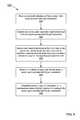
- FIG. 9is a flowchart illustrating a method 1000 of using an FES orthosis for gait modulation according to an embodiment.
- the FES orthosiscan be any suitable neuroprosthetic and/or the like such as the orthosis 100 and/or 200 described herein.
- the orthosiscan include a frame, an electrode assembly, a sensor, and an electric stimulator, and can be coupled to and/or disposed about an impaired leg of a patient to provide FES thereto.
- the method 1000includes receiving, at the electric stimulator and from the sensor, a first signal associated with a gait characteristic, at 1001 .
- the electric stimulatorcan be substantially similar in form and function as the electric stimulator 240 described above with reference to FIG. 7 .
- the sensorcan be substantially similar in form and function as the sensor 230 described above with reference to FIG. 7 .
- the sensorcan include one or more sensing devices such as, for example, a tilt sensor, pressure sensor, accelerometer, gyroscope, etc. that can sense and/or detect the gait characteristic.
- the gait characteristiccan be associated with, for example, a “heel-off” event or the like of the impaired leg (e.g., a decrease in pressure as a result of the heel being lifted away from a surface upon which the patient is walking and/or any other suitable characteristic).
- the sensorcan sense and/or detect the gait characteristic and can send the first signal to the electric stimulator.
- the senorcan be integrated with the electric stimulator and as such, the first signal can be sent via a communication channel associated with a wired signal transmission (e.g., along a wire and/or a signal trace).
- the sensorcan be physically distinct from the electric stimulator, and as such, the first signal can be sent via a communication channel associated with a wireless signal transmission (e.g., WiFi®, Bluetooth®, etc.).
- the electric stimulatorcan include at least a memory and a processor.
- the memorycan store instructions to cause the processor to perform and/or execute one or more functions, processes, modules, and/or the like associated with calculating the one or more system parameters.
- the processorcan receive the first signal from the sensor and can calculate and/or otherwise determine the one or more system parameters associated with that gait characteristic.
- the memorycan include and/or can store a repository that includes a list of gait characteristics and a list of processes and/or functions to be executed by the processor that are associated therewith.
- the processorcan, for example, query the repository to determine the one or more system parameters associated with the first signal received from the sensor.
- the electric stimulatorcan be in communication with a control device or the like (e.g., via a wired or wireless connection) that can include and/or store the repository.
- the control devicecan be substantially similar to the control device 260 described above with reference to FIG. 8 .
- a signalis sent from the electric stimulator to the electrode assembly to cause the electrode assembly to provide an electric stimulation to a portion of the neuromuscular system of the limb, at 1003 .
- the FES orthosiscan be disposed about and/or can at least partially envelop a portion of the impaired leg to substantially align and/or otherwise place one or more electrodes in electrical communication with, for example, the peroneal nerve of the impaired leg.
- electric stimulationis provided to a set of muscles associated with the portion of the neuromuscular system of the impaired leg, resulting in dorsiflexion of the foot of the impaired leg (i.e., a pivoting of the foot substantially about the ankle towards the leg).
- the method 1000includes receiving, at the electric stimulator and from the sensor, a second signal associated with the gait characteristic, at 1004 .
- the gait characteristiccan be associated with a “heel-on” event or the like of the impaired leg (e.g., an increase in pressure as a result of the heel being placed in contact with the surface and/or any other suitable characteristic).
- the sensorcan sense and/or detect the gait characteristic and can send the second signal to the electric stimulator.
- the electric stimulation of the portion of the neuromuscular system of the limbis terminated, at 1005 .
- the electric stimulatorcan be configured to open an electrical circuit between a power supply (e.g., that generates the electric current for stimulation) and the electrode assembly.
- the electric stimulatorcan transition the power supply or the like from an “on” state, in which electrical current is transmitted to the electrode assembly, to an “off” state or the like (e.g., sleep, hibernate, standby, etc.), in which electrical current is not transmitted to the electrode assembly.
- the electric stimulatorcan modulate an amount of stimulation (e.g., a voltage of the current provided to the electrode assembly) from a first amount resulting in, for example, the dorsiflexion of the limb to a second amount resulting in a substantially relaxing of the portion of the neuromuscular system.
- the electric stimulatorcan modulate stimulation such that an intensity of the stimulation provided to the portion of the neuromuscular system of the limb is reduced (i.e., the electric stimulator does not substantially terminate the stimulation but reduces the amount of stimulation to a minimal setting and/or the like).
- the electric stimulation applied to, for example, the peroneal nerveis terminated and/or modulated, thereby allowing the set of muscles associated therewith to relax.
- the foot of the impaired legcan pivot about the ankle away from the leg (i.e., plantarflexion).
- the FES orthosiscan provide functional electrical stimulation that can enhance the function of the impaired leg to facilitate gait.
- the method 1000 described aboveincludes the electric stimulator receiving a first signal and a second signal from the sensor, in some instances, the sensor can be configured to send any number of signals to the electric stimulator that can be, for example, associated with adjusting one or more parameters of the electric stimulation provided to the neuromuscular system of the limb.
- the senorcan send the signal to the electric stimulator (i.e., at 1003 ) and can be configured to sense and/or otherwise detect an amount of the dorsiflexion and/or inversion or eversion of the foot in response to the electric stimulation and based on the sensed and/or detected characteristic, can send one or more signals to the electric stimulator (i.e., prior to the signal sent at 1004 ) associated with adjusting one or more parameters of the electric stimulation (e.g., a voltage provided to one or more portions of the electrode assembly and/or the like).
- the electric stimulatorcan terminate and/or modulate the electric stimulation based on any set of signals, parameters, history, and/or the like.
- the electric stimulatorcan receive the second signal from the sensor and can compare data included in and/or represented by the second signal with historical data such as, for example, a previous gait event and/or the like.
- the electric stimulatorcan be configured to adjust, terminate, and/or modulate the electric stimulation provided to the portion of the neuromuscular based at least in part on the second signal and/or any other data associated with a gate event, characteristic, and/or parameter.
- FIG. 10is a flowchart illustrating a method 1100 of using an FES orthosis for gait modulation according to an embodiment.
- the FES orthosiscan be any suitable neuroprosthetic and/or the like such as the orthosis 100 and/or 200 described herein.
- the orthosiscan include a frame, an electrode assembly, a sensor, and an electric stimulator, and can be coupled to and/or disposed about an impaired leg of a patient to provide FES thereto.
- the method 1100includes receiving, at the electric stimulator and from a control device, a first signal that is associated with a system parameter via a first communication channel, at 1101 .
- the control devicecan be any suitable device such as, for example, the control devices 160 , 260 , and/or 260 ′ described herein.
- the first communication channelcan be associated with a wireless communication over a network.
- the electric stimulatorcan include a communication device such as the communication device 248 in FIG. 7 , which can communicate with one or more electronic devices.
- the network and the communication channelcan be any suitable network and communication channel, respectively, such as those described herein.
- the networkcan be a personal area network (PAN) and the communication channel can be associated with Bluetooth®.
- PANpersonal area network
- the system parametercan be associated with, for example, an initialization of the FES orthosis.
- the patientcan be receiving FES therapy for the first time and as such, system parameters and/or settings of the FES orthosis may not be appropriately defined for the patient.
- a health care providercan manipulate the control device (e.g., a smart phone, a PC, a tablet, etc.) to define an initial set of system characteristics and/or a second of calibration parameters for the FES orthosis that are uniquely established for the patient.
- a health care professionalcan manipulate the control device to define the system parameter substantially remotely (e.g., at a location physically distinct from the FES orthosis).
- the health care professionalcan be at a medical facility and can manipulate the control device to define the system parameter and can send the first signal via, for example, a LAN and the Internet to the FES orthosis worn by a patient that is at his or her home (or any other location other than the medical facility).
- a second signalthat is associated with a confirmation of the system parameter is sent from the electric stimulator to the control device, at 1102 .
- the second signalcan be sent in a similar manner as described with reference to the first signal.
- the electric stimulatorreceives a third signal that is from the sensor via a second communication channel, different from the first communication channel, at 1103 .
- the sensorcan be substantially similar in form and function as the sensor 230 described above with reference to FIG. 7 .
- the sensorcan include one or more sensing devices such as, for example, a tilt sensor, pressure sensor, accelerometer, gyroscope, etc. that can sense and/or detect the gait characteristic.
- the gait characteristiccan be associated with, for example, a “heel-off” event or the like of the impaired leg (e.g., a decrease in pressure as a result of the heel being lifted away from a surface upon which the patient is walking and/or any other suitable characteristic).
- the gait characteristiccan be associated with any suitable gait event.
- a fourth signalis sent, from the electric stimulator to the electrode assembly, to cause the electrode assembly to provide an electric stimulation to a portion of a neuromuscular system of the limb (e.g., the impaired leg), at 1104 .
- the FES orthosiscan be disposed about and/or can at least partially envelop a portion of the impaired leg to substantially align and/or otherwise place one or more electrodes included in the electrode assembly in electrical communication with, for example, the peroneal nerve of the impaired leg.
- the FES orthosiscan be used to enhance limb function of the impaired leg to mitigate the effects of, for example, lower leg paralysis such as drop foot or the like.
- an FES orthosiscan include a frame, an electrode assembly, a sensor, and an electric stimulator and can be adapted to enhance the function of a patients hand or the like.
- the sensor of such FES orthosiscan be configured to sense and/or detect one or more characteristics associated with the function of the hand and can send a signal to the electric stimulator (in a similar manner as described above) that is associated with the one or more characteristics.
- the electric stimulatorcan generate an electrical current that can be transmitted through one or more electrodes included in the electrode assembly, thereby providing FES to one or more nerves associated with the function of the hand.
- an FES orthosiscan include and/or can otherwise be coupled to an electrode assembly that can be at least partially disposed within a portion of the body of the patient.
- an FES orthosiscan be operably coupled to an electrode assembly that includes electrodes disposed within the body of a patient.
- the electrode assemblycan be disposed within the body in such a manner that the electrodes are disposed adjacent to and/or in electrical communication with, for example, the peroneal nerve, the tibial nerve, and/or any other suitable portion of a neuromuscular system of the patient.
- the electrode assemblycan include one or more external connectors configured to place the electrodes disposed within the body in electrical communication with an electric device that is disposed externally of the body. In other embodiments, the electrode assembly need not include such connectors and can transmit a flow of electrical current via, for example, inductive coupling and/or the like.
- an FES orthosiscan include and/or can otherwise be in communication with one or more sensors disposed within the body of a patient.
- a relatively small sensorcan be subcutaneously implanted into a portion of the patient's foot, ankle, lower leg, upper leg, and/or any other suitable portion of the body.
- Some embodiments described hereinrelate to a computer storage product with a non-transitory computer-readable medium (also can be referred to as a non-transitory processor-readable medium) having instructions or computer code thereon for performing various computer-implemented operations.
- the computer-readable mediumor processor-readable medium
- the media and computer codemay be those designed and constructed for the specific purpose or purposes.
- non-transitory computer-readable mediainclude, but are not limited to, magnetic storage media such as hard disks, floppy disks, and magnetic tape; optical storage media such as Compact Disc/Digital Video Discs (CD/DVDs), Compact Disc-Read Only Memories (CD-ROMs), and holographic devices; magneto-optical storage media such as optical disks; carrier wave signal processing modules; and hardware devices that are specially configured to store and execute program code, such as Application-Specific Integrated Circuits (ASICs), Programmable Logic Devices (PLDs), Read-Only Memory (ROM) and Random-Access Memory (RAM) devices.
- ASICsApplication-Specific Integrated Circuits
- PLDsProgrammable Logic Devices
- ROMRead-Only Memory
- RAMRandom-Access Memory
- Other embodiments described hereinrelate to a computer program product, which can include, for example, the instructions and/or computer code discussed herein.
- Hardware modulesmay include, for example, a general-purpose processor, a field programmable gate array (FPGA), and/or an application specific integrated circuit (ASIC).
- Software modules (executed on hardware)can be expressed in a variety of software languages (e.g., computer code), including C, C++, JavaTM, Ruby, Visual BasicTM, and/or other object-oriented, procedural, or other programming language and development tools.
- Examples of computer codeinclude, but are not limited to, micro-code or micro-instructions, machine instructions, such as produced by a compiler, code used to produce a web service, and files containing higher-level instructions that are executed by a computer using an interpreter. Additional examples of computer code include, but are not limited to, control signals, encrypted code, and compressed code.
Landscapes
- Health & Medical Sciences (AREA)
- Life Sciences & Earth Sciences (AREA)
- Animal Behavior & Ethology (AREA)
- Public Health (AREA)
- Veterinary Medicine (AREA)
- General Health & Medical Sciences (AREA)
- Engineering & Computer Science (AREA)
- Biomedical Technology (AREA)
- Heart & Thoracic Surgery (AREA)
- Biophysics (AREA)
- Molecular Biology (AREA)
- Medical Informatics (AREA)
- Physics & Mathematics (AREA)
- Pathology (AREA)
- Surgery (AREA)
- Physical Education & Sports Medicine (AREA)
- Nuclear Medicine, Radiotherapy & Molecular Imaging (AREA)
- Radiology & Medical Imaging (AREA)
- Transplantation (AREA)
- Physiology (AREA)
- Dentistry (AREA)
- Oral & Maxillofacial Surgery (AREA)
- Electrotherapy Devices (AREA)
- Rehabilitation Tools (AREA)
Abstract
Description
Claims (23)
Priority Applications (12)
| Application Number | Priority Date | Filing Date | Title |
|---|---|---|---|
| US14/223,340US9867985B2 (en) | 2014-03-24 | 2014-03-24 | Systems and apparatus for gait modulation and methods of use |
| JP2016547617AJP6563934B2 (en) | 2014-03-24 | 2015-03-17 | Walking adjustment system and device and method of use |
| CA2936989ACA2936989C (en) | 2014-03-24 | 2015-03-17 | Systems and apparatus for gait modulation and methods of use |
| AU2015236546AAU2015236546B2 (en) | 2014-03-24 | 2015-03-17 | Systems and apparatus for gait modulation and methods of use |
| EP15770404.0AEP3122419B1 (en) | 2014-03-24 | 2015-03-17 | Systems and apparatus for gait modulation and methods of use |
| PCT/US2015/020992WO2015148184A1 (en) | 2014-03-24 | 2015-03-17 | Systems and apparatus for gait modulation and methods of use |
| EP23173917.8AEP4252645A3 (en) | 2014-03-24 | 2015-03-17 | Systems and apparatus for gait modulation and methods of use |
| US15/872,634US10086196B2 (en) | 2014-03-24 | 2018-01-16 | Systems and apparatus for gait modulation and methods of use |
| US16/146,368US10850098B2 (en) | 2014-03-24 | 2018-09-28 | Systems and apparatus for gait modulation and methods of use |
| AU2020202739AAU2020202739A1 (en) | 2014-03-24 | 2020-04-24 | Systems and apparatus for gait modulation and methods of use |
| US17/103,249US11691009B2 (en) | 2014-03-24 | 2020-11-24 | Systems and apparatus for gait modulation and methods of use |
| US18/142,837US12377266B2 (en) | 2014-03-24 | 2023-05-03 | Systems and apparatus for gait modulation and methods of use |
Applications Claiming Priority (1)
| Application Number | Priority Date | Filing Date | Title |
|---|---|---|---|
| US14/223,340US9867985B2 (en) | 2014-03-24 | 2014-03-24 | Systems and apparatus for gait modulation and methods of use |
Related Child Applications (2)
| Application Number | Title | Priority Date | Filing Date |
|---|---|---|---|
| US15/872,634ContinuationUS10086196B2 (en) | 2014-03-24 | 2018-01-16 | Systems and apparatus for gait modulation and methods of use |
| US15/872,634DivisionUS10086196B2 (en) | 2014-03-24 | 2018-01-16 | Systems and apparatus for gait modulation and methods of use |
Publications (2)
| Publication Number | Publication Date |
|---|---|
| US20150265834A1 US20150265834A1 (en) | 2015-09-24 |
| US9867985B2true US9867985B2 (en) | 2018-01-16 |
Family
ID=54141095
Family Applications (5)
| Application Number | Title | Priority Date | Filing Date |
|---|---|---|---|
| US14/223,340ActiveUS9867985B2 (en) | 2014-03-24 | 2014-03-24 | Systems and apparatus for gait modulation and methods of use |
| US15/872,634ActiveUS10086196B2 (en) | 2014-03-24 | 2018-01-16 | Systems and apparatus for gait modulation and methods of use |
| US16/146,368Active2034-05-06US10850098B2 (en) | 2014-03-24 | 2018-09-28 | Systems and apparatus for gait modulation and methods of use |
| US17/103,249Active2034-07-19US11691009B2 (en) | 2014-03-24 | 2020-11-24 | Systems and apparatus for gait modulation and methods of use |
| US18/142,837ActiveUS12377266B2 (en) | 2014-03-24 | 2023-05-03 | Systems and apparatus for gait modulation and methods of use |
Family Applications After (4)
| Application Number | Title | Priority Date | Filing Date |
|---|---|---|---|
| US15/872,634ActiveUS10086196B2 (en) | 2014-03-24 | 2018-01-16 | Systems and apparatus for gait modulation and methods of use |
| US16/146,368Active2034-05-06US10850098B2 (en) | 2014-03-24 | 2018-09-28 | Systems and apparatus for gait modulation and methods of use |
| US17/103,249Active2034-07-19US11691009B2 (en) | 2014-03-24 | 2020-11-24 | Systems and apparatus for gait modulation and methods of use |
| US18/142,837ActiveUS12377266B2 (en) | 2014-03-24 | 2023-05-03 | Systems and apparatus for gait modulation and methods of use |
Country Status (6)
| Country | Link |
|---|---|
| US (5) | US9867985B2 (en) |
| EP (2) | EP3122419B1 (en) |
| JP (1) | JP6563934B2 (en) |
| AU (2) | AU2015236546B2 (en) |
| CA (1) | CA2936989C (en) |
| WO (1) | WO2015148184A1 (en) |
Cited By (4)
| Publication number | Priority date | Publication date | Assignee | Title |
|---|---|---|---|---|
| US10086196B2 (en) | 2014-03-24 | 2018-10-02 | Bioness Inc. | Systems and apparatus for gait modulation and methods of use |
| DE102019118402A1 (en)* | 2019-07-08 | 2021-01-14 | Markus Bresser | Targeted electromyostimulation |
| US11077300B2 (en) | 2016-01-11 | 2021-08-03 | Bioness Inc. | Systems and apparatus for gait modulation and methods of use |
| US11484710B2 (en) | 2019-01-07 | 2022-11-01 | Evolution Devices, Inc. | Device and system for real-time gait modulation and methods of operation thereof |
Families Citing this family (22)
| Publication number | Priority date | Publication date | Assignee | Title |
|---|---|---|---|---|
| US8972017B2 (en) | 2005-11-16 | 2015-03-03 | Bioness Neuromodulation Ltd. | Gait modulation system and method |
| US7899556B2 (en) | 2005-11-16 | 2011-03-01 | Bioness Neuromodulation Ltd. | Orthosis for a gait modulation system |
| EP2586489B1 (en) | 2006-05-01 | 2014-12-24 | Bioness Neuromodulation Ltd | Improved functional electrical stimulation systems |
| AU2014397167B2 (en)* | 2014-06-13 | 2019-05-23 | FESIA Technology, S.L. | System and method for functional electrical stimulation |
| KR102494900B1 (en) | 2016-03-15 | 2023-02-01 | 나이키 이노베이트 씨.브이. | Capacitive Foot Presence Detection for Footwear |
| US11357290B2 (en) | 2016-03-15 | 2022-06-14 | Nike, Inc. | Active footwear sensor calibration |
| CN106377837A (en)* | 2016-09-19 | 2017-02-08 | 天津大学 | Functional muscle electrical stimulation walk-assisting device based on gait recognition and control method |
| CN106345055A (en)* | 2016-09-19 | 2017-01-25 | 天津大学 | Gait recognition-based functional electrical muscular stimulation walking aid |
| RU2681707C2 (en)* | 2016-09-21 | 2019-03-12 | Общество с ограниченной ответственностью "Лаборатория умной ортопедии" | Orthosis for treatment of foot paresis |
| CN106333692A (en)* | 2016-11-15 | 2017-01-18 | 上海市共进通信技术有限公司 | The leg or foot wearing device and method for detecting human gait cycle and step length |
| JP7066360B2 (en)* | 2017-09-20 | 2022-05-13 | マクセル株式会社 | Electrical muscle stimulator |
| CN111629779B (en)* | 2018-03-13 | 2024-05-10 | 克云股份公司 | Gait correction system to prevent degenerative changes in joints and ligaments in dogs |
| JP6886559B2 (en)* | 2018-03-30 | 2021-06-16 | 三井化学株式会社 | Vibration stimulation application system |
| CN108771574B (en)* | 2018-07-02 | 2021-04-27 | 国家康复辅具研究中心 | Intelligent scoliosis correction system and control method |
| BR112020026910A2 (en)* | 2018-07-03 | 2021-03-30 | Moterum Technologies, Inc. | DISTRIBUTED SYSTEM ARCHITECTURE FOR GEAR MONITORING AND METHODS OF USE |
| CL2018001900A1 (en) | 2018-07-12 | 2018-10-05 | Biomedical Devices Spa | System and method of functional electro stimulation that allows to deliver coordinated and natural movements for people or animals with damage to the motor system |
| WO2020202171A1 (en)* | 2019-03-29 | 2020-10-08 | Sameer Sudhir Karpe | Customised ankle foot orthotic device |
| JP7433855B2 (en)* | 2019-11-25 | 2024-02-20 | ヤーマン株式会社 | support equipment |
| PT3965866T (en) | 2020-05-27 | 2023-10-06 | Manuel Galvez Gamiz | Electrophysiology system |
| US12186223B2 (en) | 2020-06-09 | 2025-01-07 | Aifree Interactive Technology Co., Ltd. | Wearable interface for intelligent health promotion service system |
| US12005573B2 (en) | 2020-12-06 | 2024-06-11 | Cionic, Inc. | Mobility based on machine-learned movement determination |
| US11957605B2 (en) | 2020-12-06 | 2024-04-16 | Cionic, Inc. | Machine-learned movement determination based on intent identification |
Citations (161)
| Publication number | Priority date | Publication date | Assignee | Title |
|---|---|---|---|---|
| US3204637A (en) | 1963-02-07 | 1965-09-07 | Erich J Frank | Stimulating apparatus |
| US3344792A (en) | 1965-01-13 | 1967-10-03 | Franklin F Offner | Method of muscular stimulation in human beings to aid in walking |
| US3426748A (en) | 1965-11-23 | 1969-02-11 | Gen Electric | Stimulator analyzer and locater |
| US3881496A (en) | 1967-12-22 | 1975-05-06 | Philips Corp | Apparatus and method for electrically stimulating leg muscles |
| US3941137A (en) | 1971-02-27 | 1976-03-02 | U.S. Philips Corporation | Ambulatory stimulator |
| US4381012A (en) | 1980-09-24 | 1983-04-26 | Wallant International Trade, Inc. | Electrode placement device |
| US4432368A (en) | 1980-09-24 | 1984-02-21 | Wallant International Trade, Inc. | Automatic electrode placement device |
| JPS60119949A (en) | 1983-12-02 | 1985-06-27 | 三輪精機株式会社 | Walking aid apparatus by electric stimulation |
| US4528984A (en) | 1983-04-25 | 1985-07-16 | Empi, Inc. | Autoprogrammable functional electrical stimulation apparatus and method |
| US4558704A (en) | 1983-12-15 | 1985-12-17 | Wright State University | Hand control system |
| US4569352A (en) | 1983-05-13 | 1986-02-11 | Wright State University | Feedback control system for walking |
| US4580569A (en) | 1983-12-15 | 1986-04-08 | Wright State University | Apparatus and method for muscle stimulation |
| US4586495A (en) | 1984-07-02 | 1986-05-06 | Wright State University | Therapy system for acute patient care |
| US4647918A (en) | 1985-01-16 | 1987-03-03 | Goforth William P | Multi-event notification system for monitoring critical pressure points on persons with diminished sensation of the feet |
| US4697808A (en) | 1985-05-16 | 1987-10-06 | Wright State University | Walking assistance system |
| US4745930A (en) | 1986-10-16 | 1988-05-24 | Chattanooga Corporation | Force sensing insole for electro-goniometer |
| US4832033A (en) | 1985-04-29 | 1989-05-23 | Bio-Medical Research Limited | Electrical stimulation of muscle |
| US4976264A (en) | 1989-05-10 | 1990-12-11 | Therapeutic Technologies Inc. | Power muscle stimulator |
| US4996987A (en) | 1989-05-10 | 1991-03-05 | Therapeutic Technologies Inc. | Power muscle stimulator |
| US5016635A (en) | 1988-11-29 | 1991-05-21 | Sigmedics, Inc. Of Delaware | Control of FNS via pattern variations of response EMG |
| US5081989A (en) | 1989-04-07 | 1992-01-21 | Sigmedics, Inc. | Microprocessor-controlled enhanced multiplexed functional electrical stimulator for surface stimulation in paralyzed patients |
| US5112296A (en) | 1991-04-30 | 1992-05-12 | The Board Of Supervisors Of Louisiana State University | Biofeedback activated orthosis for foot-drop rehabilitation |
| US5121747A (en)* | 1985-11-06 | 1992-06-16 | University Of Strathclyde | Hybrid orthosis |
| US5167229A (en) | 1986-03-24 | 1992-12-01 | Case Western Reserve University | Functional neuromuscular stimulation system |
| US5253654A (en) | 1992-04-30 | 1993-10-19 | Thomas Berten R | Orthopedic weight monitor |
| US5277697A (en) | 1990-08-17 | 1994-01-11 | Hanger Orthopedic Group, Inc. | Patella-femoral brace |
| US5285781A (en) | 1990-05-26 | 1994-02-15 | Stiwell S. A. | Electrical neuromuscular stimulation device |
| JPH06501854A (en) | 1989-04-07 | 1994-03-03 | シグメディクス・インコーポレイテッド | Microprocessor-controlled, enhanced, and multiplexed functional electrical stimulator for surface stimulation of paralyzed patients |
| US5300096A (en) | 1992-06-03 | 1994-04-05 | Hall H Eugene | Electromyographic treatment device |
| US5318597A (en) | 1993-03-15 | 1994-06-07 | Cardiac Pacemakers, Inc. | Rate adaptive cardiac rhythm management device control algorithm using trans-thoracic ventilation |
| US5323650A (en) | 1993-01-14 | 1994-06-28 | Fullen Systems, Inc. | System for continuously measuring forces applied to the foot |
| US5330516A (en) | 1991-03-28 | 1994-07-19 | Ben-Gurion University Of The Negev Research & Development Authority | Device for generating hand function |
| US5350414A (en) | 1991-12-10 | 1994-09-27 | Electro Science Technologies, Inc. | Local application microprocessor based nerve and muscle stimulator |
| US5357696A (en) | 1992-05-01 | 1994-10-25 | Gray Frank B | Device for measuring force applied to a wearer's foot |
| US5408873A (en) | 1994-07-25 | 1995-04-25 | Cleveland Medical Devices, Inc. | Foot force sensor |
| US5433737A (en) | 1990-03-30 | 1995-07-18 | Medisan S.R.L. | Method for the electrical stimulation of a group of muscles in order to improve their appearance, and apparatus for carrying out the method |
| US5437619A (en) | 1993-06-30 | 1995-08-01 | Empi, Inc. | Range-of-motion splint with eccentric spring |
| US5476441A (en) | 1993-09-30 | 1995-12-19 | Massachusetts Institute Of Technology | Controlled-brake orthosis |
| US5487759A (en) | 1993-06-14 | 1996-01-30 | Bastyr; Charles A. | Nerve stimulating device and associated support device |
| US5540735A (en) | 1994-12-12 | 1996-07-30 | Rehabilicare, Inc. | Apparatus for electro-stimulation of flexing body portions |
| US5562707A (en) | 1993-10-13 | 1996-10-08 | Sim & Mcburney | Garment for applying controlled electrical stimulation to restore motor function |
| US5566479A (en) | 1995-03-21 | 1996-10-22 | Gray; Frank B. | Shoe contruction for use by diabetic persons |
| US5628722A (en) | 1995-03-03 | 1997-05-13 | Solomonow; Moshe | Method for maintaining knee stability of a user suffering from damage of a knee ligament |
| US5643332A (en) | 1995-09-20 | 1997-07-01 | Neuromotion Inc. | Assembly for functional electrical stimulation during movement |
| US5664346A (en) | 1994-05-04 | 1997-09-09 | Barker; Dale E. | Portable footwear illuminated |
| US5724996A (en) | 1996-09-24 | 1998-03-10 | Galaxy-Top International S.P.A. | Method for controlled stimulation of predetermined parts of the human body by application of variable electric signals |
| US5748845A (en) | 1995-07-31 | 1998-05-05 | Motorola, Inc. | FES method and system for controlling the movement of a limb |
| US5775332A (en) | 1992-07-01 | 1998-07-07 | Goldman; Robert J. | Capacitive biofeedback sensor with resilient polyurethane dielectric for rehabilation |
| US5843142A (en) | 1997-03-27 | 1998-12-01 | Sultan; Hashem | Voice activated loco motor device and method of use for spinal cord injuries |
| US5851191A (en) | 1997-07-01 | 1998-12-22 | Neurometrix, Inc. | Apparatus and methods for assessment of neuromuscular function |
| US5861017A (en) | 1997-06-06 | 1999-01-19 | Shriners Hospitals For Children | Portable functional electrical stimulation (FES) system for upper or lower extremity applications |
| US5916159A (en) | 1995-07-28 | 1999-06-29 | Unilead International, Inc. | Electrode equipped electro-dermal device |
| US5951598A (en) | 1997-01-14 | 1999-09-14 | Heartstream, Inc. | Electrode system |
| US5980472A (en) | 1998-02-20 | 1999-11-09 | Seyl; V. Craig | Joint movement monitoring system |
| US6002965A (en) | 1998-06-10 | 1999-12-14 | Katz; Amiram | Self applied device and method for prevention of deep vein thrombosis |
| DE19830359A1 (en) | 1998-07-07 | 2000-01-20 | Helge Zwosta | Spatial position and movement determination of body and body parts for remote control of machine and instruments |
| US6064912A (en) | 1997-03-28 | 2000-05-16 | Kenney; John P. | Orthotic/electrotherapy for treating contractures due to immobility |
| US6126355A (en) | 1998-08-31 | 2000-10-03 | Otto Bock, U.S., Inc. | Fastener for adjustable support device |
| US6129695A (en) | 1996-12-18 | 2000-10-10 | Peters; Rick | Athletic brace |
| US6174294B1 (en) | 1996-08-02 | 2001-01-16 | Orbital Technologies, Inc. | Limb load monitor |
| US6195921B1 (en) | 1999-09-28 | 2001-03-06 | Vinncente Hoa Gia Truong | Virtual intelligence shoe with a podiatric analysis system |
| US6236890B1 (en) | 1996-06-13 | 2001-05-22 | The Victoria University Of Manchester | Stimulation of muscles |
| US6246863B1 (en) | 1997-11-28 | 2001-06-12 | Gerald Kampel | Avalanche transceiver |
| US6261247B1 (en) | 1998-12-31 | 2001-07-17 | Ball Semiconductor, Inc. | Position sensing system |
| US6308102B1 (en) | 1999-09-29 | 2001-10-23 | Stimsoft, Inc. | Patient interactive neurostimulation system and method |
| US6349126B2 (en) | 2000-04-14 | 2002-02-19 | Omron Corporation | Pedometer capable of keeping user interested in exercise |
| US6379313B1 (en) | 1997-07-01 | 2002-04-30 | Neurometrix, Inc. | Methods for the assessment of neuromuscular function by F-wave latency |
| US20020077688A1 (en) | 2000-12-15 | 2002-06-20 | Kirkland Thomas C. | Electrode-positioning body garment |
| JP2002191580A (en) | 2000-10-16 | 2002-07-09 | Omron Corp | Unit for detecting body motion |
| US6445955B1 (en) | 1999-07-08 | 2002-09-03 | Stephen A. Michelson | Miniature wireless transcutaneous electrical neuro or muscular-stimulation unit |
| US6456885B1 (en) | 1999-03-29 | 2002-09-24 | Kurume University | Apparatus for strengthening muscles |
| US6496739B2 (en) | 2000-04-11 | 2002-12-17 | N.E.S.S. Neuromuscular Electrical Stimulation Systems Ltd. | Electrode positioner for a splint to be used for muscle stimulation |
| US6507757B1 (en) | 2000-06-20 | 2003-01-14 | Ian Douglas Swain | Apparatus for electrical stimulation of the body |
| US20030014087A1 (en) | 2001-03-30 | 2003-01-16 | Neurocontrol Corporation | Systems and methods for performing prosthetic or therapeutic neuromuscular stimulation using a programmable universal external controller |
| US6516500B2 (en) | 2000-06-07 | 2003-02-11 | First Create Co., Ltd. | Plastic clipping device |
| US20030065368A1 (en) | 2001-08-17 | 2003-04-03 | Martin Van Der Hoeven | Muscle stimulator apparatus |
| US20030083596A1 (en) | 1997-04-21 | 2003-05-01 | Immersion Corporation | Goniometer-based body-tracking device and method |
| US6564103B2 (en) | 2000-12-01 | 2003-05-13 | Visionquest Industries, Inc. | Electrical stimulator and method of use |
| US6567706B2 (en) | 2000-03-20 | 2003-05-20 | N.E.S.S. Neuromuscular Electrical Stimulation Systems Ltd. | Electrode for muscle stimulation |
| US6571115B2 (en) | 2000-12-26 | 2003-05-27 | Axelgaard Manufacturing Company, Ltd. | Compress garment facilitating the use of medical electrodes |
| US20030114894A1 (en) | 2001-12-18 | 2003-06-19 | N.E.S.S. Neuromuscular Electrical Stimulation Systems Ltd. | Scanning electrode system for a neuroprosthesis |
| US6607500B2 (en) | 1999-07-08 | 2003-08-19 | Cyclotec Advanced Medical Technologies, Inc. | Integrated cast and muscle stimulation system |
| US6651352B2 (en) | 2002-01-04 | 2003-11-25 | Liberty Mutual | Wrist motion measurement device |
| US20040015203A1 (en) | 2000-05-08 | 2004-01-22 | Mcgraw Michael B. | Multi-functional portable electro-medical device |
| US20040011366A1 (en) | 1997-02-26 | 2004-01-22 | Schulman Joseph H. | System of implantable devices for monitoring and/or affecting body parameters |
| JP2004503266A (en) | 2000-04-18 | 2004-02-05 | モトローラ・インコーポレイテッド | Wireless system protocol for telemetry monitoring |
| US6701189B2 (en) | 2001-03-30 | 2004-03-02 | Neurocontrol Corporation | Systems and methods for performing prosthetic or therapeutic neuromuscular stimulation using a universal external controller accommodating different control inputs and/or different control outputs |
| US20040044381A1 (en) | 2000-08-14 | 2004-03-04 | Duncan Michael Robert | Muscle fatigue meter |
| US20040082979A1 (en) | 2002-10-23 | 2004-04-29 | Kai-Yu Tong | Functional electrical stimulation system |
| US20040133081A1 (en) | 2002-10-09 | 2004-07-08 | Eric Teller | Method and apparatus for auto journaling of continuous or discrete body states utilizing physiological and/or contextual parameters |
| US20040147975A1 (en) | 2001-04-24 | 2004-07-29 | Popovic Dejan P. | Functional electrical therapy system (fets) |
| JP2004215735A (en) | 2003-01-10 | 2004-08-05 | Kyushu Hitachi Maxell Ltd | Low frequency treatment device |
| USD494273S1 (en) | 2002-09-19 | 2004-08-10 | Neurodan A/S (A Danish Company) | Pressure sensor |
| US20040172097A1 (en) | 2001-05-16 | 2004-09-02 | Roland Brodard | Therapeutic and/or training device for a person's lower limbs |
| US6788979B1 (en) | 1999-10-27 | 2004-09-07 | Axelgaard Manufacturing Co., Ltd. | Electrical stimulation compress kit |
| US20040173220A1 (en) | 2003-03-06 | 2004-09-09 | Harry Jason D. | Method and apparatus for improving human balance and gait and preventing foot injury |
| JP2004313555A (en) | 2003-04-18 | 2004-11-11 | Roudou Fukushi Jigyodan | Functional electrostimulation walking assisting device |
| WO2004098703A2 (en) | 2003-05-07 | 2004-11-18 | Bmr Research & Development Limited | Apparatus for applying electrical current to the neuromuscular system |
| US20040243197A1 (en) | 2000-11-20 | 2004-12-02 | Demian Bassem M. | Bunion treating device |
| US20040249316A1 (en) | 2001-10-18 | 2004-12-09 | Jun Ashihara | Walking condition determining device and method |
| US20040254624A1 (en) | 2003-06-06 | 2004-12-16 | Prizm Medical, Inc. | Electrical stimulator and garment electrode connection system |
| US6836744B1 (en) | 2000-08-18 | 2004-12-28 | Fareid A. Asphahani | Portable system for analyzing human gait |
| EP1508302A2 (en) | 2003-08-22 | 2005-02-23 | Alfred E. Mann Foundation for Scientific Research | A system for determining relative distance(s) and/or angle(s) between at least two points |
| US20050043660A1 (en) | 2003-03-31 | 2005-02-24 | Izex Technologies, Inc. | Orthoses |
| US20050049652A1 (en) | 2003-08-25 | 2005-03-03 | Kai-Yu Tong | Functional electrical stimulation system |
| US20050085704A1 (en) | 2003-10-14 | 2005-04-21 | Christian Schulz | Variable pressure reusable sensor |
| JP2005514143A (en) | 2002-01-08 | 2005-05-19 | インターナショナル・ビジネス・マシーンズ・コーポレーション | Emergency call and patient localization system for implanted automatic defibrillators |
| US20050131317A1 (en) | 2002-04-12 | 2005-06-16 | Oddsson Lars I.E. | Sensor prosthetic for improved balance control |
| US20050192645A1 (en) | 2004-01-28 | 2005-09-01 | Stein Richard B. | Method to produce a balanced dorsiflexion during the gait of patients with foot drop |
| US20050261609A1 (en) | 2004-05-24 | 2005-11-24 | 6121438 Canada Inc. | Foot sensor apparatus, method & system |
| US6978684B2 (en) | 2003-11-10 | 2005-12-27 | Nike, Inc. | Apparel that dynamically, consciously, and/or reflexively affects subject performance |
| US20060015470A1 (en) | 2004-07-14 | 2006-01-19 | Richard Lauer | Neural prosthesis with fuzzy logic control system |
| US20060020421A1 (en) | 1997-10-02 | 2006-01-26 | Fitsense Technology, Inc. | Monitoring activity of a user in locomotion on foot |
| US20060111756A1 (en) | 2004-11-23 | 2006-05-25 | Chang Henry H | Method and apparatus for a neuromuscular stimulator |
| JP2006166244A (en) | 2004-12-09 | 2006-06-22 | Toshiba Corp | Network telephone system and main device of the network telephone system |
| JP2006192276A (en) | 2005-01-14 | 2006-07-27 | Samsung Electronics Co Ltd | Activity pattern monitoring method and apparatus |
| US20060211956A1 (en) | 2003-08-21 | 2006-09-21 | Yoshiyuki Sankai | Wearable action-assist device, and method and program for controlling wearable action-assist device |
| US7146220B2 (en) | 2001-09-30 | 2006-12-05 | N.E.S.S. Neuromuscular Electrical Stimulation Systems Ltd. | Device for muscle stimulation |
| US20060276704A1 (en) | 2005-06-03 | 2006-12-07 | Mcginnis William J | Neurophysiological electrode placement apparel |
| US20060282017A1 (en) | 2002-07-11 | 2006-12-14 | Arik Avni | Force sensor system for use in monitoring weight bearing |
| US20060282018A1 (en) | 2005-05-23 | 2006-12-14 | Alfiero Balzano | Sensor and analyzer for determining physiological limitations |
| US20070021689A1 (en) | 2005-07-19 | 2007-01-25 | University Of Nebraska Medical Center | Method and system for assessing locomotive bio-rhythms |
| US20070123756A1 (en) | 2005-10-14 | 2007-05-31 | Konica Minolta Sensing, Inc. | Vital information measuring device |
| US20070130893A1 (en) | 2005-11-23 | 2007-06-14 | Davies Michael A M | Animal instrumentation |
| US20070179560A1 (en) | 2002-10-23 | 2007-08-02 | Kai-Yu Tong | Functional electrical stimulation system |
| US7257448B2 (en) | 2001-01-16 | 2007-08-14 | Bmr Research & Development Limited | Apparatus for stimulating a muscle of a subject |
| US20070197946A1 (en) | 2004-03-10 | 2007-08-23 | Robert Gilmour | Orthotic Device and Segemented Liner |
| US20070203533A1 (en) | 2005-08-30 | 2007-08-30 | Bioq, Inc. | Implantable medical device for restoration of neurological function impaired by peripheral neuropathy |
| WO2008005865A1 (en) | 2006-06-30 | 2008-01-10 | Drexel University | Orthosis and method of use for treatment and rehabilitation of dropfoot |
| US20080033505A1 (en) | 2001-10-19 | 2008-02-07 | The University Of Sydney | Muscle stimulation systems |
| US20080045872A1 (en) | 2004-02-25 | 2008-02-21 | Bauerfeind Ag | Elastic Bandage with Electrodes Spaced Apart From One Another |
| US7359751B1 (en) | 2004-05-05 | 2008-04-15 | Advanced Neuromodulation Systems, Inc. | Clinician programmer for use with trial stimulator |
| US20080140154A1 (en) | 2006-07-05 | 2008-06-12 | University Of Southern California | Flexible Communication and Control Protocol for a Wireless Sensor and Microstimulator Network |
| US20080154335A1 (en) | 2004-02-12 | 2008-06-26 | Ndi Medical, Llc | Portable assemblies, systems and methods for providing functional or therapeutic neuromuscular stimulation |
| US7403821B2 (en) | 2000-02-17 | 2008-07-22 | Neurodan A/S | Method and implantable systems for neural sensing and nerve stimulation |
| US20080177355A1 (en) | 2004-03-16 | 2008-07-24 | Medtronic, Inc. | Collecting activity information to evaluate therapy |
| US7410471B1 (en) | 1998-09-18 | 2008-08-12 | Becker Orthopedic Appliance Company | Orthosis knee joint and sensor |
| US7416537B1 (en) | 1999-06-23 | 2008-08-26 | Izex Technologies, Inc. | Rehabilitative orthoses |
| US20080294080A1 (en) | 2007-04-23 | 2008-11-27 | Golden Crab S.L. | Exoskeleton |
| US20080319349A1 (en) | 2005-04-18 | 2008-12-25 | Yitzhak Zilberman | System and Related Method For Determining a Measurement Between Locations on a Body |
| US20090012436A1 (en)* | 2006-02-17 | 2009-01-08 | Koninklijke Philips Electronics N.V. | Orthosis and treatment method |
| US20090043357A1 (en) | 2007-08-07 | 2009-02-12 | The Hong Kong Polytechnic University | Wireless real-time feedback control functional electrical stimulation system |
| US7537573B2 (en) | 2002-11-25 | 2009-05-26 | Tibion Corporation | Active muscle assistance and resistance device and method |
| US20090149917A1 (en) | 2007-12-06 | 2009-06-11 | Advanced Bionics Corporation | Multimodal neurostimulation systems and methods |
| JP2009530064A (en) | 2006-03-22 | 2009-08-27 | エモーティブ システムズ ピーティーワイ リミテッド | Electrode and electrode headset |
| US7632239B2 (en) | 2005-11-16 | 2009-12-15 | Bioness Neuromodulation Ltd. | Sensor device for gait enhancement |
| US7713217B2 (en) | 2001-06-27 | 2010-05-11 | Honda Giken Kogyo Kabushiki Kaisha | Torque imparting system |
| US7756585B2 (en) | 2006-01-31 | 2010-07-13 | Good Samaritan Children's Therapy Unit | Muscle stimulation method and system to improve walking |
| US7899556B2 (en) | 2005-11-16 | 2011-03-01 | Bioness Neuromodulation Ltd. | Orthosis for a gait modulation system |
| US20110137375A1 (en)* | 2009-12-03 | 2011-06-09 | Mcbride Keith | System and method for detection of inversion and eversion of the foot using a multi-chamber insole |
| US8070703B2 (en) | 2004-03-10 | 2011-12-06 | Vision Quest Industries Incorporated | Electrically stimulating orthotic device and segmented liner |
| US20120059432A1 (en) | 2010-09-07 | 2012-03-08 | Aalborg Universitet | Method and device for reflex-based functional gait training |
| US8209022B2 (en) | 2005-11-16 | 2012-06-26 | Bioness Neuromodulation Ltd. | Gait modulation system and method |
| US20120203156A1 (en) | 2011-02-07 | 2012-08-09 | Amit Dar | Adjustable orthosis for electrical stimulation of a limb |
| US20130131555A1 (en) | 2011-11-17 | 2013-05-23 | William R. Hook | Gait analysis using angular rate reversal |
| WO2014030295A1 (en) | 2012-08-24 | 2014-02-27 | パナソニック 株式会社 | Body movement-detecting device and electric stimulation device provided with same |
| US20140180361A1 (en) | 2011-03-24 | 2014-06-26 | California Institute Of Technology | Neurostimulator |
| US8788049B2 (en) | 2006-05-01 | 2014-07-22 | Bioness Neuromodulation Ltd. | Functional electrical stimulation systems |
| US8868217B2 (en) | 2011-06-27 | 2014-10-21 | Bioness Neuromodulation Ltd. | Electrode for muscle stimulation |
| US8972017B2 (en) | 2005-11-16 | 2015-03-03 | Bioness Neuromodulation Ltd. | Gait modulation system and method |
| US20150321000A1 (en) | 2013-01-21 | 2015-11-12 | Kathryn H. Rosenbluth | Devices and methods for controlling tremor |
Family Cites Families (15)
| Publication number | Priority date | Publication date | Assignee | Title |
|---|---|---|---|---|
| JPH05293188A (en)* | 1992-04-21 | 1993-11-09 | Nec San-Ei Instr Co Ltd | Living body function reformation system by electric stimulating device |
| JP2002200104A (en)* | 2000-12-28 | 2002-07-16 | Japan Science & Technology Corp | Hybrid FES device with short leg orthosis |
| US6587728B2 (en) | 2001-03-30 | 2003-07-01 | Neurocontrol Corporation | Systems and methods for performing prosthetic or therapeutic neuromuscular stimulation using an external, battery powered controller with power conservation features |
| IES20010651A2 (en) | 2001-07-12 | 2003-01-22 | Bmr Res & Dev Ltd | A method and apparatus for applying electrical stimulation to a human or animal subject |
| US8346367B2 (en) | 2002-09-11 | 2013-01-01 | Meagan Medical, Inc. | Apparatus and method for stabilizing, improving mobility, and controlling cartilage matrix degradation of weight-bearing articular joints |
| US7216001B2 (en) | 2003-01-22 | 2007-05-08 | Medtronic Xomed, Inc. | Apparatus for intraoperative neural monitoring |
| CA2863933C (en) | 2004-12-22 | 2018-08-07 | Ossur Hf | Systems and methods for processing limb motion |
| US20080154113A1 (en) | 2006-06-12 | 2008-06-26 | Yitzhak Zilberman | Apparatus and method for positioning electrodes on the body |
| US8419713B1 (en) | 2012-08-01 | 2013-04-16 | The University Of Utah Research Foundation | Carrier assembly with caps for medical connectors |
| GB2474239B (en) | 2009-10-06 | 2011-10-19 | Salisbury Nhs Foundation Trust | Apparatus for electrical stimulation of the body |
| US20130053922A1 (en) | 2009-10-22 | 2013-02-28 | Zaghloul Ahmed | Dipole electrical stimulation employing direct current for recovery from spinal cord injury |
| CA2913074C (en) | 2013-05-30 | 2023-09-12 | Graham H. Creasey | Topical neurological stimulation |
| US9867985B2 (en) | 2014-03-24 | 2018-01-16 | Bioness Inc. | Systems and apparatus for gait modulation and methods of use |
| AU2014397167B2 (en) | 2014-06-13 | 2019-05-23 | FESIA Technology, S.L. | System and method for functional electrical stimulation |
| WO2017123608A1 (en) | 2016-01-11 | 2017-07-20 | Bioness Inc. | Systems and apparatus for gait modulation and methods of use |
- 2014
- 2014-03-24USUS14/223,340patent/US9867985B2/enactiveActive
- 2015
- 2015-03-17CACA2936989Apatent/CA2936989C/enactiveActive
- 2015-03-17EPEP15770404.0Apatent/EP3122419B1/enactiveActive
- 2015-03-17EPEP23173917.8Apatent/EP4252645A3/enactivePending
- 2015-03-17WOPCT/US2015/020992patent/WO2015148184A1/enactiveApplication Filing
- 2015-03-17AUAU2015236546Apatent/AU2015236546B2/enactiveActive
- 2015-03-17JPJP2016547617Apatent/JP6563934B2/enactiveActive
- 2018
- 2018-01-16USUS15/872,634patent/US10086196B2/enactiveActive
- 2018-09-28USUS16/146,368patent/US10850098B2/enactiveActive
- 2020
- 2020-04-24AUAU2020202739Apatent/AU2020202739A1/ennot_activeAbandoned
- 2020-11-24USUS17/103,249patent/US11691009B2/enactiveActive
- 2023
- 2023-05-03USUS18/142,837patent/US12377266B2/enactiveActive
Patent Citations (183)
| Publication number | Priority date | Publication date | Assignee | Title |
|---|---|---|---|---|
| US3204637A (en) | 1963-02-07 | 1965-09-07 | Erich J Frank | Stimulating apparatus |
| US3344792A (en) | 1965-01-13 | 1967-10-03 | Franklin F Offner | Method of muscular stimulation in human beings to aid in walking |
| US3426748A (en) | 1965-11-23 | 1969-02-11 | Gen Electric | Stimulator analyzer and locater |
| US3881496A (en) | 1967-12-22 | 1975-05-06 | Philips Corp | Apparatus and method for electrically stimulating leg muscles |
| US3941137A (en) | 1971-02-27 | 1976-03-02 | U.S. Philips Corporation | Ambulatory stimulator |
| US4381012A (en) | 1980-09-24 | 1983-04-26 | Wallant International Trade, Inc. | Electrode placement device |
| US4432368A (en) | 1980-09-24 | 1984-02-21 | Wallant International Trade, Inc. | Automatic electrode placement device |
| US4528984A (en) | 1983-04-25 | 1985-07-16 | Empi, Inc. | Autoprogrammable functional electrical stimulation apparatus and method |
| US4569352A (en) | 1983-05-13 | 1986-02-11 | Wright State University | Feedback control system for walking |
| JPS60119949A (en) | 1983-12-02 | 1985-06-27 | 三輪精機株式会社 | Walking aid apparatus by electric stimulation |
| US4558704A (en) | 1983-12-15 | 1985-12-17 | Wright State University | Hand control system |
| US4580569A (en) | 1983-12-15 | 1986-04-08 | Wright State University | Apparatus and method for muscle stimulation |
| US4586495A (en) | 1984-07-02 | 1986-05-06 | Wright State University | Therapy system for acute patient care |
| US4647918A (en) | 1985-01-16 | 1987-03-03 | Goforth William P | Multi-event notification system for monitoring critical pressure points on persons with diminished sensation of the feet |
| US4832033A (en) | 1985-04-29 | 1989-05-23 | Bio-Medical Research Limited | Electrical stimulation of muscle |
| US4697808A (en) | 1985-05-16 | 1987-10-06 | Wright State University | Walking assistance system |
| US5121747A (en)* | 1985-11-06 | 1992-06-16 | University Of Strathclyde | Hybrid orthosis |
| US5167229A (en) | 1986-03-24 | 1992-12-01 | Case Western Reserve University | Functional neuromuscular stimulation system |
| US4745930A (en) | 1986-10-16 | 1988-05-24 | Chattanooga Corporation | Force sensing insole for electro-goniometer |
| US5016635A (en) | 1988-11-29 | 1991-05-21 | Sigmedics, Inc. Of Delaware | Control of FNS via pattern variations of response EMG |
| JPH06501854A (en) | 1989-04-07 | 1994-03-03 | シグメディクス・インコーポレイテッド | Microprocessor-controlled, enhanced, and multiplexed functional electrical stimulator for surface stimulation of paralyzed patients |
| US5081989A (en) | 1989-04-07 | 1992-01-21 | Sigmedics, Inc. | Microprocessor-controlled enhanced multiplexed functional electrical stimulator for surface stimulation in paralyzed patients |
| US4996987A (en) | 1989-05-10 | 1991-03-05 | Therapeutic Technologies Inc. | Power muscle stimulator |
| US4976264A (en) | 1989-05-10 | 1990-12-11 | Therapeutic Technologies Inc. | Power muscle stimulator |
| US5433737A (en) | 1990-03-30 | 1995-07-18 | Medisan S.R.L. | Method for the electrical stimulation of a group of muscles in order to improve their appearance, and apparatus for carrying out the method |
| US5285781A (en) | 1990-05-26 | 1994-02-15 | Stiwell S. A. | Electrical neuromuscular stimulation device |
| US5277697A (en) | 1990-08-17 | 1994-01-11 | Hanger Orthopedic Group, Inc. | Patella-femoral brace |
| US5330516A (en) | 1991-03-28 | 1994-07-19 | Ben-Gurion University Of The Negev Research & Development Authority | Device for generating hand function |
| US5112296A (en) | 1991-04-30 | 1992-05-12 | The Board Of Supervisors Of Louisiana State University | Biofeedback activated orthosis for foot-drop rehabilitation |
| US5350414A (en) | 1991-12-10 | 1994-09-27 | Electro Science Technologies, Inc. | Local application microprocessor based nerve and muscle stimulator |
| US5253654A (en) | 1992-04-30 | 1993-10-19 | Thomas Berten R | Orthopedic weight monitor |
| US5357696A (en) | 1992-05-01 | 1994-10-25 | Gray Frank B | Device for measuring force applied to a wearer's foot |
| US5300096A (en) | 1992-06-03 | 1994-04-05 | Hall H Eugene | Electromyographic treatment device |
| US5775332A (en) | 1992-07-01 | 1998-07-07 | Goldman; Robert J. | Capacitive biofeedback sensor with resilient polyurethane dielectric for rehabilation |
| US5323650A (en) | 1993-01-14 | 1994-06-28 | Fullen Systems, Inc. | System for continuously measuring forces applied to the foot |
| US5318597A (en) | 1993-03-15 | 1994-06-07 | Cardiac Pacemakers, Inc. | Rate adaptive cardiac rhythm management device control algorithm using trans-thoracic ventilation |
| US5487759A (en) | 1993-06-14 | 1996-01-30 | Bastyr; Charles A. | Nerve stimulating device and associated support device |
| US5437619A (en) | 1993-06-30 | 1995-08-01 | Empi, Inc. | Range-of-motion splint with eccentric spring |
| US5476441A (en) | 1993-09-30 | 1995-12-19 | Massachusetts Institute Of Technology | Controlled-brake orthosis |
| US5562707A (en) | 1993-10-13 | 1996-10-08 | Sim & Mcburney | Garment for applying controlled electrical stimulation to restore motor function |
| US5664346A (en) | 1994-05-04 | 1997-09-09 | Barker; Dale E. | Portable footwear illuminated |
| US5408873A (en) | 1994-07-25 | 1995-04-25 | Cleveland Medical Devices, Inc. | Foot force sensor |
| US5540735A (en) | 1994-12-12 | 1996-07-30 | Rehabilicare, Inc. | Apparatus for electro-stimulation of flexing body portions |
| US5628722A (en) | 1995-03-03 | 1997-05-13 | Solomonow; Moshe | Method for maintaining knee stability of a user suffering from damage of a knee ligament |
| US5566479A (en) | 1995-03-21 | 1996-10-22 | Gray; Frank B. | Shoe contruction for use by diabetic persons |
| US5916159A (en) | 1995-07-28 | 1999-06-29 | Unilead International, Inc. | Electrode equipped electro-dermal device |
| US5748845A (en) | 1995-07-31 | 1998-05-05 | Motorola, Inc. | FES method and system for controlling the movement of a limb |
| US5643332A (en) | 1995-09-20 | 1997-07-01 | Neuromotion Inc. | Assembly for functional electrical stimulation during movement |
| US5814093A (en) | 1995-09-20 | 1998-09-29 | Neuromotion Inc. | Assembly for functional electrical stimulation during movement |
| US6236890B1 (en) | 1996-06-13 | 2001-05-22 | The Victoria University Of Manchester | Stimulation of muscles |
| US6174294B1 (en) | 1996-08-02 | 2001-01-16 | Orbital Technologies, Inc. | Limb load monitor |
| US5724996A (en) | 1996-09-24 | 1998-03-10 | Galaxy-Top International S.P.A. | Method for controlled stimulation of predetermined parts of the human body by application of variable electric signals |
| US6129695A (en) | 1996-12-18 | 2000-10-10 | Peters; Rick | Athletic brace |
| US5951598A (en) | 1997-01-14 | 1999-09-14 | Heartstream, Inc. | Electrode system |
| US20040011366A1 (en) | 1997-02-26 | 2004-01-22 | Schulman Joseph H. | System of implantable devices for monitoring and/or affecting body parameters |
| US5843142A (en) | 1997-03-27 | 1998-12-01 | Sultan; Hashem | Voice activated loco motor device and method of use for spinal cord injuries |
| US6456884B1 (en) | 1997-03-28 | 2002-09-24 | Trestles Healthcare, Inc. | Orthotic/electrotherapy for treating contractures due to immobility |
| US6064912A (en) | 1997-03-28 | 2000-05-16 | Kenney; John P. | Orthotic/electrotherapy for treating contractures due to immobility |
| US20030083596A1 (en) | 1997-04-21 | 2003-05-01 | Immersion Corporation | Goniometer-based body-tracking device and method |
| US5983140A (en) | 1997-06-06 | 1999-11-09 | Shriners Hospitals For Children | Portable functional electrical stimulation (FES) system for upper or lower extremity applications |
| US5861017A (en) | 1997-06-06 | 1999-01-19 | Shriners Hospitals For Children | Portable functional electrical stimulation (FES) system for upper or lower extremity applications |
| US6379313B1 (en) | 1997-07-01 | 2002-04-30 | Neurometrix, Inc. | Methods for the assessment of neuromuscular function by F-wave latency |
| US5851191A (en) | 1997-07-01 | 1998-12-22 | Neurometrix, Inc. | Apparatus and methods for assessment of neuromuscular function |
| US20060020421A1 (en) | 1997-10-02 | 2006-01-26 | Fitsense Technology, Inc. | Monitoring activity of a user in locomotion on foot |
| US7200517B2 (en) | 1997-10-02 | 2007-04-03 | Nike, Inc. | Monitoring activity of a user in locomotion on foot |
| US6246863B1 (en) | 1997-11-28 | 2001-06-12 | Gerald Kampel | Avalanche transceiver |
| US5980472A (en) | 1998-02-20 | 1999-11-09 | Seyl; V. Craig | Joint movement monitoring system |
| US6282448B1 (en) | 1998-06-10 | 2001-08-28 | Amiram Katz | Self applied and self adjusting device and method for prevention of deep vein thrombosis with movement detection |
| US6002965A (en) | 1998-06-10 | 1999-12-14 | Katz; Amiram | Self applied device and method for prevention of deep vein thrombosis |
| DE19830359A1 (en) | 1998-07-07 | 2000-01-20 | Helge Zwosta | Spatial position and movement determination of body and body parts for remote control of machine and instruments |
| US6126355A (en) | 1998-08-31 | 2000-10-03 | Otto Bock, U.S., Inc. | Fastener for adjustable support device |
| US7410471B1 (en) | 1998-09-18 | 2008-08-12 | Becker Orthopedic Appliance Company | Orthosis knee joint and sensor |
| US6261247B1 (en) | 1998-12-31 | 2001-07-17 | Ball Semiconductor, Inc. | Position sensing system |
| US6456885B1 (en) | 1999-03-29 | 2002-09-24 | Kurume University | Apparatus for strengthening muscles |
| US7416537B1 (en) | 1999-06-23 | 2008-08-26 | Izex Technologies, Inc. | Rehabilitative orthoses |
| US6445955B1 (en) | 1999-07-08 | 2002-09-03 | Stephen A. Michelson | Miniature wireless transcutaneous electrical neuro or muscular-stimulation unit |
| US6607500B2 (en) | 1999-07-08 | 2003-08-19 | Cyclotec Advanced Medical Technologies, Inc. | Integrated cast and muscle stimulation system |
| US6195921B1 (en) | 1999-09-28 | 2001-03-06 | Vinncente Hoa Gia Truong | Virtual intelligence shoe with a podiatric analysis system |
| US6308102B1 (en) | 1999-09-29 | 2001-10-23 | Stimsoft, Inc. | Patient interactive neurostimulation system and method |
| US6788979B1 (en) | 1999-10-27 | 2004-09-07 | Axelgaard Manufacturing Co., Ltd. | Electrical stimulation compress kit |
| US7403821B2 (en) | 2000-02-17 | 2008-07-22 | Neurodan A/S | Method and implantable systems for neural sensing and nerve stimulation |
| US6567706B2 (en) | 2000-03-20 | 2003-05-20 | N.E.S.S. Neuromuscular Electrical Stimulation Systems Ltd. | Electrode for muscle stimulation |
| US6496739B2 (en) | 2000-04-11 | 2002-12-17 | N.E.S.S. Neuromuscular Electrical Stimulation Systems Ltd. | Electrode positioner for a splint to be used for muscle stimulation |
| US6349126B2 (en) | 2000-04-14 | 2002-02-19 | Omron Corporation | Pedometer capable of keeping user interested in exercise |
| JP2004503266A (en) | 2000-04-18 | 2004-02-05 | モトローラ・インコーポレイテッド | Wireless system protocol for telemetry monitoring |
| US20040015203A1 (en) | 2000-05-08 | 2004-01-22 | Mcgraw Michael B. | Multi-functional portable electro-medical device |
| US6988005B2 (en) | 2000-05-08 | 2006-01-17 | International Rehabilitative Sciences, Inc. | Multi-functional portable electro-medical device |
| US6516500B2 (en) | 2000-06-07 | 2003-02-11 | First Create Co., Ltd. | Plastic clipping device |
| US6507757B1 (en) | 2000-06-20 | 2003-01-14 | Ian Douglas Swain | Apparatus for electrical stimulation of the body |
| US20040044381A1 (en) | 2000-08-14 | 2004-03-04 | Duncan Michael Robert | Muscle fatigue meter |
| US6836744B1 (en) | 2000-08-18 | 2004-12-28 | Fareid A. Asphahani | Portable system for analyzing human gait |
| JP2002191580A (en) | 2000-10-16 | 2002-07-09 | Omron Corp | Unit for detecting body motion |
| US6700499B2 (en) | 2000-10-16 | 2004-03-02 | Omron Corporation | Body motion detector |
| US20040243197A1 (en) | 2000-11-20 | 2004-12-02 | Demian Bassem M. | Bunion treating device |
| US6564103B2 (en) | 2000-12-01 | 2003-05-13 | Visionquest Industries, Inc. | Electrical stimulator and method of use |
| US20020077688A1 (en) | 2000-12-15 | 2002-06-20 | Kirkland Thomas C. | Electrode-positioning body garment |
| US6571115B2 (en) | 2000-12-26 | 2003-05-27 | Axelgaard Manufacturing Company, Ltd. | Compress garment facilitating the use of medical electrodes |
| US7257448B2 (en) | 2001-01-16 | 2007-08-14 | Bmr Research & Development Limited | Apparatus for stimulating a muscle of a subject |
| US6701189B2 (en) | 2001-03-30 | 2004-03-02 | Neurocontrol Corporation | Systems and methods for performing prosthetic or therapeutic neuromuscular stimulation using a universal external controller accommodating different control inputs and/or different control outputs |
| US20030014087A1 (en) | 2001-03-30 | 2003-01-16 | Neurocontrol Corporation | Systems and methods for performing prosthetic or therapeutic neuromuscular stimulation using a programmable universal external controller |
| US20040147975A1 (en) | 2001-04-24 | 2004-07-29 | Popovic Dejan P. | Functional electrical therapy system (fets) |
| US20040172097A1 (en) | 2001-05-16 | 2004-09-02 | Roland Brodard | Therapeutic and/or training device for a person's lower limbs |
| US7713217B2 (en) | 2001-06-27 | 2010-05-11 | Honda Giken Kogyo Kabushiki Kaisha | Torque imparting system |
| US20030065368A1 (en) | 2001-08-17 | 2003-04-03 | Martin Van Der Hoeven | Muscle stimulator apparatus |
| US7146220B2 (en) | 2001-09-30 | 2006-12-05 | N.E.S.S. Neuromuscular Electrical Stimulation Systems Ltd. | Device for muscle stimulation |
| US20040249316A1 (en) | 2001-10-18 | 2004-12-09 | Jun Ashihara | Walking condition determining device and method |
| US20080033505A1 (en) | 2001-10-19 | 2008-02-07 | The University Of Sydney | Muscle stimulation systems |
| US20040122483A1 (en) | 2001-12-18 | 2004-06-24 | N.E.S.S. Neuromuscular Electrical Stimulation Systems Ltd. | Neuroprosthesis system for improved lower-limb function |
| US7337007B2 (en) | 2001-12-18 | 2008-02-26 | Ness Neuromuscular Electrical Stimulation Systems Ltd. | Surface neuroprosthetic device having a locating system |
| US6829510B2 (en) | 2001-12-18 | 2004-12-07 | Ness Neuromuscular Electrical Stimulation Systems Ltd. | Surface neuroprosthetic device having an internal cushion interface system |
| US20030114894A1 (en) | 2001-12-18 | 2003-06-19 | N.E.S.S. Neuromuscular Electrical Stimulation Systems Ltd. | Scanning electrode system for a neuroprosthesis |
| WO2003051453A2 (en) | 2001-12-18 | 2003-06-26 | N.E.S.S. Neuromuscular Electrical Stimulation Systems Ltd. | Device for muscle stimulation |
| US6651352B2 (en) | 2002-01-04 | 2003-11-25 | Liberty Mutual | Wrist motion measurement device |
| JP2005514143A (en) | 2002-01-08 | 2005-05-19 | インターナショナル・ビジネス・マシーンズ・コーポレーション | Emergency call and patient localization system for implanted automatic defibrillators |
| US20050131317A1 (en) | 2002-04-12 | 2005-06-16 | Oddsson Lars I.E. | Sensor prosthetic for improved balance control |
| US20060282017A1 (en) | 2002-07-11 | 2006-12-14 | Arik Avni | Force sensor system for use in monitoring weight bearing |
| USD494273S1 (en) | 2002-09-19 | 2004-08-10 | Neurodan A/S (A Danish Company) | Pressure sensor |
| US20040133081A1 (en) | 2002-10-09 | 2004-07-08 | Eric Teller | Method and apparatus for auto journaling of continuous or discrete body states utilizing physiological and/or contextual parameters |
| US20070179560A1 (en) | 2002-10-23 | 2007-08-02 | Kai-Yu Tong | Functional electrical stimulation system |
| US20040082979A1 (en) | 2002-10-23 | 2004-04-29 | Kai-Yu Tong | Functional electrical stimulation system |
| US7162305B2 (en) | 2002-10-23 | 2007-01-09 | The Hong Kong Polytechnic University | Functional electrical stimulation system |
| US7537573B2 (en) | 2002-11-25 | 2009-05-26 | Tibion Corporation | Active muscle assistance and resistance device and method |
| JP2004215735A (en) | 2003-01-10 | 2004-08-05 | Kyushu Hitachi Maxell Ltd | Low frequency treatment device |
| US20040173220A1 (en) | 2003-03-06 | 2004-09-09 | Harry Jason D. | Method and apparatus for improving human balance and gait and preventing foot injury |
| US20050043660A1 (en) | 2003-03-31 | 2005-02-24 | Izex Technologies, Inc. | Orthoses |
| JP2004313555A (en) | 2003-04-18 | 2004-11-11 | Roudou Fukushi Jigyodan | Functional electrostimulation walking assisting device |
| US20070106343A1 (en) | 2003-05-07 | 2007-05-10 | B M R Research & Developments Limited | Apparatus for applying electrical current to the neuromuscular system |
| WO2004098703A2 (en) | 2003-05-07 | 2004-11-18 | Bmr Research & Development Limited | Apparatus for applying electrical current to the neuromuscular system |
| US20040254624A1 (en) | 2003-06-06 | 2004-12-16 | Prizm Medical, Inc. | Electrical stimulator and garment electrode connection system |
| US20060211956A1 (en) | 2003-08-21 | 2006-09-21 | Yoshiyuki Sankai | Wearable action-assist device, and method and program for controlling wearable action-assist device |
| US7785279B2 (en) | 2003-08-21 | 2010-08-31 | University Of Tsukuba | Wearable action-assist device, and method and program for controlling wearable action-assist device |
| EP1508302A2 (en) | 2003-08-22 | 2005-02-23 | Alfred E. Mann Foundation for Scientific Research | A system for determining relative distance(s) and/or angle(s) between at least two points |
| US20050049652A1 (en) | 2003-08-25 | 2005-03-03 | Kai-Yu Tong | Functional electrical stimulation system |
| US20050085704A1 (en) | 2003-10-14 | 2005-04-21 | Christian Schulz | Variable pressure reusable sensor |
| US6978684B2 (en) | 2003-11-10 | 2005-12-27 | Nike, Inc. | Apparel that dynamically, consciously, and/or reflexively affects subject performance |
| US20050192645A1 (en) | 2004-01-28 | 2005-09-01 | Stein Richard B. | Method to produce a balanced dorsiflexion during the gait of patients with foot drop |
| US20080154335A1 (en) | 2004-02-12 | 2008-06-26 | Ndi Medical, Llc | Portable assemblies, systems and methods for providing functional or therapeutic neuromuscular stimulation |
| US20080045872A1 (en) | 2004-02-25 | 2008-02-21 | Bauerfeind Ag | Elastic Bandage with Electrodes Spaced Apart From One Another |
| US20070197946A1 (en) | 2004-03-10 | 2007-08-23 | Robert Gilmour | Orthotic Device and Segemented Liner |
| US8070703B2 (en) | 2004-03-10 | 2011-12-06 | Vision Quest Industries Incorporated | Electrically stimulating orthotic device and segmented liner |
| US20080177355A1 (en) | 2004-03-16 | 2008-07-24 | Medtronic, Inc. | Collecting activity information to evaluate therapy |
| US7359751B1 (en) | 2004-05-05 | 2008-04-15 | Advanced Neuromodulation Systems, Inc. | Clinician programmer for use with trial stimulator |
| US20050261609A1 (en) | 2004-05-24 | 2005-11-24 | 6121438 Canada Inc. | Foot sensor apparatus, method & system |
| US20060015470A1 (en) | 2004-07-14 | 2006-01-19 | Richard Lauer | Neural prosthesis with fuzzy logic control system |
| US20060111756A1 (en) | 2004-11-23 | 2006-05-25 | Chang Henry H | Method and apparatus for a neuromuscular stimulator |
| JP2006166244A (en) | 2004-12-09 | 2006-06-22 | Toshiba Corp | Network telephone system and main device of the network telephone system |
| JP2006192276A (en) | 2005-01-14 | 2006-07-27 | Samsung Electronics Co Ltd | Activity pattern monitoring method and apparatus |
| US20080319349A1 (en) | 2005-04-18 | 2008-12-25 | Yitzhak Zilberman | System and Related Method For Determining a Measurement Between Locations on a Body |
| US20060282018A1 (en) | 2005-05-23 | 2006-12-14 | Alfiero Balzano | Sensor and analyzer for determining physiological limitations |
| US20060276704A1 (en) | 2005-06-03 | 2006-12-07 | Mcginnis William J | Neurophysiological electrode placement apparel |
| US20070021689A1 (en) | 2005-07-19 | 2007-01-25 | University Of Nebraska Medical Center | Method and system for assessing locomotive bio-rhythms |
| US20070203533A1 (en) | 2005-08-30 | 2007-08-30 | Bioq, Inc. | Implantable medical device for restoration of neurological function impaired by peripheral neuropathy |
| US20070123756A1 (en) | 2005-10-14 | 2007-05-31 | Konica Minolta Sensing, Inc. | Vital information measuring device |
| US8382688B2 (en) | 2005-11-16 | 2013-02-26 | Bioness Neuromodulation Ltd. | Sensor device for gait enhancement |
| US7899556B2 (en) | 2005-11-16 | 2011-03-01 | Bioness Neuromodulation Ltd. | Orthosis for a gait modulation system |
| US8209022B2 (en) | 2005-11-16 | 2012-06-26 | Bioness Neuromodulation Ltd. | Gait modulation system and method |
| US8209036B2 (en) | 2005-11-16 | 2012-06-26 | Bioness Neuromodulation Ltd. | Orthosis for a gait modulation system |
| US20140303705A1 (en) | 2005-11-16 | 2014-10-09 | Bioness Neuromodulation Ltd. | Orthosis for a gait modulation system |
| US7632239B2 (en) | 2005-11-16 | 2009-12-15 | Bioness Neuromodulation Ltd. | Sensor device for gait enhancement |
| US20150273205A1 (en) | 2005-11-16 | 2015-10-01 | Bioness Neuromodulation Ltd. | Gait modulation system and method |
| US8972017B2 (en) | 2005-11-16 | 2015-03-03 | Bioness Neuromodulation Ltd. | Gait modulation system and method |
| US8694110B2 (en) | 2005-11-16 | 2014-04-08 | Bioness Neuromodulation Ltd. | Orthosis for gait modulation |
| US20070130893A1 (en) | 2005-11-23 | 2007-06-14 | Davies Michael A M | Animal instrumentation |
| US7756585B2 (en) | 2006-01-31 | 2010-07-13 | Good Samaritan Children's Therapy Unit | Muscle stimulation method and system to improve walking |
| US20090012436A1 (en)* | 2006-02-17 | 2009-01-08 | Koninklijke Philips Electronics N.V. | Orthosis and treatment method |
| JP2009530064A (en) | 2006-03-22 | 2009-08-27 | エモーティブ システムズ ピーティーワイ リミテッド | Electrode and electrode headset |
| US20150080979A1 (en) | 2006-05-01 | 2015-03-19 | Bioness Neuromodulation Ltd. | Functional electrical stimulation systems |
| US9415205B2 (en) | 2006-05-01 | 2016-08-16 | Bioness Neuromodulation Ltd. | Functional electrical stimulation systems |
| US8788049B2 (en) | 2006-05-01 | 2014-07-22 | Bioness Neuromodulation Ltd. | Functional electrical stimulation systems |
| WO2008005865A1 (en) | 2006-06-30 | 2008-01-10 | Drexel University | Orthosis and method of use for treatment and rehabilitation of dropfoot |
| US20080140154A1 (en) | 2006-07-05 | 2008-06-12 | University Of Southern California | Flexible Communication and Control Protocol for a Wireless Sensor and Microstimulator Network |
| US20080294080A1 (en) | 2007-04-23 | 2008-11-27 | Golden Crab S.L. | Exoskeleton |
| US20090043357A1 (en) | 2007-08-07 | 2009-02-12 | The Hong Kong Polytechnic University | Wireless real-time feedback control functional electrical stimulation system |
| US20090149917A1 (en) | 2007-12-06 | 2009-06-11 | Advanced Bionics Corporation | Multimodal neurostimulation systems and methods |
| US20110137375A1 (en)* | 2009-12-03 | 2011-06-09 | Mcbride Keith | System and method for detection of inversion and eversion of the foot using a multi-chamber insole |
| US20120059432A1 (en) | 2010-09-07 | 2012-03-08 | Aalborg Universitet | Method and device for reflex-based functional gait training |
| US20120203156A1 (en) | 2011-02-07 | 2012-08-09 | Amit Dar | Adjustable orthosis for electrical stimulation of a limb |
| US9095417B2 (en) | 2011-02-07 | 2015-08-04 | Bioness Neuromodulation Ltd. | Adjustable orthosis for electrical stimulation of a limb |
| US20140180361A1 (en) | 2011-03-24 | 2014-06-26 | California Institute Of Technology | Neurostimulator |
| US8868217B2 (en) | 2011-06-27 | 2014-10-21 | Bioness Neuromodulation Ltd. | Electrode for muscle stimulation |
| US20130131555A1 (en) | 2011-11-17 | 2013-05-23 | William R. Hook | Gait analysis using angular rate reversal |
| WO2014030295A1 (en) | 2012-08-24 | 2014-02-27 | パナソニック 株式会社 | Body movement-detecting device and electric stimulation device provided with same |
| US20150321000A1 (en) | 2013-01-21 | 2015-11-12 | Kathryn H. Rosenbluth | Devices and methods for controlling tremor |
Non-Patent Citations (97)
| Title |
|---|
| "Clinical evaluation of the ljubljana functional electrical peroneal brace," Subcommittee on Evaluation, Committee on Prosthetics Research and Development Division of Medical Sciences—National Research Council, National Academy of Sciences, Washington, D.C., Report E-7 (1973). |
| Alon, G. et al., "Persons with C5 or C6 tetraplegia achieve selected functional gains using a neuroprosthesis," Arch. Phys. Med. Rehabil., 84:119-124 (Jan. 2003). |
| Bajd, et al., "Funcational Electrical Stimulation: standing and walking after spinal cord injury," CRC Press, Boca Raton, Florida, 1989 (Table of Contents). |
| Bogataj, U. et al., "Preliminary testing of a dual-channel electrical stimulator for correction of gait," Journal of Rehabilitation Research and Development, vol. 24, No. 3, pp. 75-80, Summer 1987. Retrieved from the Internet: Dec. 29, 2016, <URL: http://www.rehab.research.va.gov/jour/87/24/3/pdf/bogataj.pdf>. |
| Burridge, et al., "Two-channel stimulation for hemiplegic gait. Control Algorithms, selection of muscle groups and the result of preliminary clinical trial," 6th Internet World Congress for Biomedical Sciences, INABIS 2000. |
| Daly, W. K., "Electrodes installed in roll-on suspension sleeves," From "MEC '02 The Next Generation," Proceedings of the 2002 MyoElectric Controls/Powered Prosthetics Symposium, Fredericton, New Brunswick, Canada: Aug. 21-23, 2002, University of New Brunswick, 3 pages. |
| Davis, R. et al., "Evaluation of electrical stimulation as a treatment for the reduction of spasticity," Bulletin of Prosthetics Research, Department of Medicine and Surgery Veterans Administration, Washington, D.C., pp. 302-309 (1974). |
| Duncan, R. M., "Basic principles of splinting the hand," Journal of the American Physical Therapy Association, 69(12):1104-1116 (1989). |
| European Search Report for European Application No. 12197261.6, dated Mar. 28, 2013. |
| Examination Report for Australian Application No. 2006314072, dated Jul. 5, 2011, 2 pages. |
| Examination Report for Australian Application No. 2006314072, dated May 5, 2010, 4 pages. |
| Examination Report for European Application No. 07736271.3, dated Dec. 14, 2010. |
| Examination Report for European Application No. 07736271.3, dated Nov. 14, 2011. |
| Examiner's Answer to Appeal Brief for U.S. Appl. No. 12/630,199, dated Aug. 14, 2012. |
| Hart, R. L. et al., "A comparison between control methods for implanted FES hand-grasp systems," IEEE Transactions on Rehabilitation Engineering, 6(2):208-218 (Jun. 1998). |
| Hendricks, H. T. et al., "Functional electrical stimulation by means of the ‘Ness Handmaster Orthosis’ in chronic stroke patients: an exploratory study," Clinical Rehabilitation, 15:217-220 (2001). |
| International Preliminary Report on Patentability for PCT/IL07/00531, dated Mar. 10, 2009. |
| International Search Report and Written Opinion for International Application No. PCT/US2010/058483, dated Feb. 7, 2011. |
| International Search Report and Written Opinion for International Application No. PCT/US2015/020992, dated Jun. 24, 2015. |
| International Search Report and Written Opinion for International Application No. PCT/US2017/012977, dated Mar. 17, 2017, 12 pages. |
| International Search Report and Written Opinion for PCT/US06/014455, dated Aug. 8, 2006. |
| International Search Report for PCT/IL06/01326, dated Oct. 13, 2009. |
| International Search Report for PCT/IL07/00531, dated Jul. 7, 2008. |
| Kralj, A. et al., "Functional electrical stimulation of the extremities: part 1," Journal of Medical Engineering and Technology, pp. 12-15 (Jan. 1977). |
| Kralj, A. et al., "Functional electrical stimulation of the extremities: part 2," Journal of Medical Engineering and Technology, pp. 75-80 (Mar. 1977). |
| Kralj, A. R. et al., "Functional Electrical Stimulation: Standing and Walking after Spinal Cord Injury," CRC Press, Boca Raton, FL., pp. 1-15 (1989). |
| Liberson, W. T. et al., "Functional Electrotherapy: Stimulation of the Peroneal Nerve Synchronized with the Swing Phase of the Gait of Hemiplegic Patients," 3rd International Congress of Physical Medicine, Session on Neuromuscular Diseases, Washington DC, Aug. 25, 1960, pp. 101-105. |
| Liberson, W. T. et al., "Functional Electrotherapy: Stimulation of the Peroneal Nerve Synchronized with the Swing Phase of the Gait of Hemiplegic Patients," Archives of Physical Medicine & Rehabilitation, pp. 101-105 (Feb. 1961). |
| NDI Medical, "About ODFS Dropped Foot Stimulator," [online] 2005 [retrieved on Jun. 5, 2006]. Retrieved from the Internet: URL: <http://www.odfs.com/About—ODFS/about—odfs.html>. |
| Ness H200 Product Specifications "H200™ Overview& Product Specifications," [online] 2006 [retrieved on Jun. 5, 2007]. Retrieved from the Internet: URL: <http://www.bionessinc.com/products/h200/htm>. |
| Neurodan, "ActiGait® An implantable drop foot correction system," Neurodan A/S—Products—ActiGait® [online] [retrieved on Jun. 5, 2007]. Retrieved from the Internet: URL: <http://www.neurodan.com/actigait.asp>. |
| NMES Guidelines for Treatment "Gait Training," [online] [retrieved on May 30, 2007]. Retrieved from the Internet: URL: <http://www.empi.com/products1nmes/gait.pdf>. |
| Notice of Reasons for Rejection for Japanese Patent Application No. 2009-517597, dated Jan. 23, 2012. |
| Notice of Reasons for Rejection for Japanese Patent Application No. 2009-517597, dated Nov. 2, 2012. |
| Office Action for Australian Patent Application No. AU 2006236428, dated Jan. 25, 2010. |
| Office Action for Australian Patent Application No. AU 2007245258, dated Apr. 12, 2012. |
| Office Action for Canadian Application No. 2,632,196, dated Mar. 16, 2010, 4 pages. |
| Office Action for Canadian Application No. 2,649,663, dated Nov. 20, 2013. |
| Office Action for Canadian Application No. 2,649,663, dated Oct. 28, 2014. |
| Office Action for European Patent Application No. EP 06750483.7, dated Apr. 16, 2009, 5 pages. |
| Office Action for Japanese Application No. 2013-149122, dated May 19, 2014. |
| Office Action for U.S. Appl. No. 10/335,905, dated Apr. 18, 2008. |
| Office Action for U.S. Appl. No. 10/335,905, dated Apr. 2, 2010. |
| Office Action for U.S. Appl. No. 10/335,905, dated Dec. 19, 2005. |
| Office Action for U.S. Appl. No. 10/335,905, dated Dec. 24, 2008. |
| Office Action for U.S. Appl. No. 10/335,905, dated Jan. 14, 2011. |
| Office Action for U.S. Appl. No. 10/335,905, dated Jan. 30, 2007. |
| Office Action for U.S. Appl. No. 10/335,905, dated Jun. 11, 2009. |
| Office Action for U.S. Appl. No. 11/380,430 dated Mar. 5, 2009. |
| Office Action for U.S. Appl. No. 11/380,430, dated Mar. 24, 2010, 12 pages. |
| Office Action for U.S. Appl. No. 11/380,430, dated Nov. 13, 2009, 8 pages. |
| Office Action for U.S. Appl. No. 11/380,430, dated Oct. 29, 2010. |
| Office Action for U.S. Appl. No. 11/380,430, dated Sep. 1, 2010, 11 pages. |
| Office Action for U.S. Appl. No. 11/552,997 dated Aug. 5, 2008. |
| Office Action for U.S. Appl. No. 11/552,997 dated Mar. 24, 2009. |
| Office Action for U.S. Appl. No. 11/552,997 dated Oct. 30, 2007. |
| Office Action for U.S. Appl. No. 12/299,043, dated Jul. 5, 2013. |
| Office Action for U.S. Appl. No. 12/299,043, dated Oct. 18, 2012. |
| Office Action for U.S. Appl. No. 12/630,199, dated Jan. 18, 2012. |
| Office Action for U.S. Appl. No. 12/630,199, dated Jun. 21, 2011. |
| Office Action for U.S. Appl. No. 12/631,095, dated Apr. 17, 2012. |
| Office Action for U.S. Appl. No. 12/631,095, dated Sep. 14, 2011. |
| Office Action for U.S. Appl. No. 13/036,256, dated Apr. 5, 2012, 8 pages. |
| Office Action for U.S. Appl. No. 13/532,597, dated Apr. 23, 2013. |
| Office Action for U.S. Appl. No. 14/245,597, dated Dec. 16, 2015, 13 pages. |
| Office Action for U.S. Appl. No. 14/245,597, dated Jun. 24, 2016, 12 pages. |
| Office Action for U.S. Appl. No. 14/333,184, dated Jun. 18, 2015. |
| Office Action for U.S. Appl. No. 14/333,184, dated Oct. 28, 2015, 7 pages. |
| Office Action for U.S. Appl. No. 14/636,628, dated Sep. 20, 2016, 12 pages. |
| Patent Examination Report No. 1 for Australian Application No. 2013260668, dated Jan. 4, 2016, 4 pages. |
| Popovic, et al., "Functional Electrical Stimulation for Grasping and Walking: Indications and Limitations," Spinal Cord, (Jun. 2001), 22 pages. |
| Popovic, et al., "Surface Stimulation Technology for Grasping and Walking Neuroprostheses—Improving Quality of Life in Stroke/Spinal Cord Injury Subjects with Rapid Prototyping and Portable FES Systems," IEEE Engineering in Medicine and Biology, Jan./Feb. 2001. |
| Popovic, M. R. et al., "Functional electrical therapy: retraining grasping in spinal cord injury," Spinal Cord, 44:143-151 (2006). |
| Popovic, M. R. et al., "Neuroprostheses for grasping," Neurological Research, 24:443-452 (Jul. 2002). |
| Prochazka, A. et al., "The bionic glove: An electrical stimulator garment that provides controlled grasp and hand opening in quadriplegia," Arch. Phys. Med. Rehabil., 78:608-614 (Jun. 1997). |
| Senelick, R. C., "Technological Advances in Stroke Rehabilitation-High Tech Marries High Touch," US Neurology, 6(2):102-104 (2010), Extract (Touch Group PLC, 4 pages). |
| Shenzhen XFT Electronics Co., Ltd., Foot Drop System, XFT-2001 User Manual, 16 pages. Retrieved from the Internet: Aug. 10, 2016, <URL: http://www.stressnomore.co.uk/downloads/instructions/91846-IFUS—1.pdf>. |
| Sowerbutt, C., "Restoring Gait in Stroke Patients Using Functional Neuromuscular Stimulation," [online] Sep. 1, 2006 [retrieved on May 30, 2007]. Retrieved from the Internet: URL: <http://appneurology.com/showArticle.jhtml?print=true&articleID=193104432>. |
| Springer, S. et al., "Dual-channel functional electrical stimulation improvements in speed-based gait classifications," Clinical Interventions in Aging, 8:271-277 (2013). |
| Springer, S. et al., "The effects of dual-channel functional electrical stimulation on stance phase sagittal kinematics in patients with hemiparesis," Journal of Electromyography and Kinesiology (2012), 7 pages, http://dx.doi.org/10.1016/j.jelekin.2012.10.017. |
| Stanic, U., "History of functional electrical stimulation," International Functional Electrical Stimulation Society, INS & IFESS Joint Congress, Sep. 16-20, 1998, Lucerne, Switzerland, 37 pages. |
| Stopar, M. et al., "New stimulators for cutaneous stimulation," Advances in External Control of Human Extremities, Proceedings of the Seventh International Symposium on External Control of Human Extremities, pp. 267-272 (1981). |
| Stralka, "Gait Training (by Stimulating Dorsiflexors)," NM III™ Neuromuscular Stimulation System Suggested Protocol, NM III Program Set #2 Program F, Rehabilicare® 920080 Rev. C. |
| Strojnik, P. et al., "Implantable stimulators for neuromuscular control," Chapter 78 in The Biomedical Engineering Handbook: Second Edition, Bronzino, J. D. (ed.), Boca Raton: CRC Press LLC (2000), 15 pages. |
| Strojnik, P. et al., "Treatment of drop foot using an implantable peroneal underknee stimulator," Scandanavian J. of Rehabil. Med. 19:37-43 (1987). |
| Supplementary European Search Report and Opinion for European Application No. 15770404.0, dated Oct. 19, 2017, 8 pages. |
| Supplementary European Search Report for European Application No. 06821561.5, dated Dec. 16, 2013. |
| Supplementary European Search Report for European Application No. 07736271.3, dated Mar. 18, 2010. |
| Supplementary European Search Report for European Application No. 10835019.0, dated Feb. 12, 2014. |
| Uellendahl, J. E. et al., "Custom silicone sockets for myoelectric prostheses," From "MEC '05 Intergrating Prosthetics and Medicine," Proceedings of the 2005 MyoElectric Controls/Powered Prosthetics Symposium, held in Fredericton, New Brunswick, Canada, Aug. 17-19, 2005, 6 pages. |
| Uellendahl, J. E. et al., "Custom silicone sockets for myoelectric prostheses," Journal of Prosthetics and Orthotics, 18(2):35-40 (2006). |
| Vodovnik, L. et al., "Functional electrical stimulation for control of locomotor systems," CRC Critical Reviews in Bioengineering, 6(2):63-131 (Sep. 1981). |
| Ward, A. R. et al., "Russian electrical stimulation: The early experiments," Physical Therapy, 82(10):1019-1030 (Oct. 2002). |
| Waters, R. et al., "Treatment of the hemiplegic upper extremity using electrical stimulation and biofeedback training," Report to the Veterans Administration, Contract V600P-1064-79, Funding Period Sep. 27, 1979-Sep. 30, 1980, pp. 251-266. |
| Waters, R. L. et al., "Effectiveness of selected surface electrodes for motor stimulation," Advances in External Control of Human Extremities, Proceedings of the Sixth International Symposium on External Control of Human Extremities, pp. 31-38 (1978). |
| Waters, R. L. et al., "Experimental correction of footdrop by electrical stimulation of the peroneal nerve," J Bone Joint Surg, vol. 57-A, No. 8 (Dec. 1975), pp. 1047-1054. |
| Wood, D.E., "Spatial sensitivity comparisons between an implanted and surface dropped foot neuromuscular stimulator," 9th Annual Conference of the International FES Society, Sep. 2004. |
Cited By (9)
| Publication number | Priority date | Publication date | Assignee | Title |
|---|---|---|---|---|
| US10086196B2 (en) | 2014-03-24 | 2018-10-02 | Bioness Inc. | Systems and apparatus for gait modulation and methods of use |
| US10850098B2 (en) | 2014-03-24 | 2020-12-01 | Bioness Inc. | Systems and apparatus for gait modulation and methods of use |
| US11691009B2 (en) | 2014-03-24 | 2023-07-04 | Bioness Inc. | Systems and apparatus for gait modulation and methods of use |
| US12377266B2 (en) | 2014-03-24 | 2025-08-05 | Bioness Medical Inc. | Systems and apparatus for gait modulation and methods of use |
| US11077300B2 (en) | 2016-01-11 | 2021-08-03 | Bioness Inc. | Systems and apparatus for gait modulation and methods of use |
| US11724106B2 (en) | 2016-01-11 | 2023-08-15 | Bioness Inc. | Systems and apparatus for gait modulation and methods of use |
| US11484710B2 (en) | 2019-01-07 | 2022-11-01 | Evolution Devices, Inc. | Device and system for real-time gait modulation and methods of operation thereof |
| DE102019118402A1 (en)* | 2019-07-08 | 2021-01-14 | Markus Bresser | Targeted electromyostimulation |
| DE102019118402B4 (en)* | 2019-07-08 | 2024-08-22 | Markus Bresser | Targeted electromyostimulation |
Also Published As
| Publication number | Publication date |
|---|---|
| CA2936989A1 (en) | 2015-10-01 |
| AU2020202739A1 (en) | 2020-05-14 |
| US20180140833A1 (en) | 2018-05-24 |
| US20210213281A1 (en) | 2021-07-15 |
| US10086196B2 (en) | 2018-10-02 |
| US12377266B2 (en) | 2025-08-05 |
| JP6563934B2 (en) | 2019-08-21 |
| EP3122419A1 (en) | 2017-02-01 |
| EP4252645A3 (en) | 2023-11-29 |
| EP3122419B1 (en) | 2023-05-24 |
| US10850098B2 (en) | 2020-12-01 |
| US11691009B2 (en) | 2023-07-04 |
| EP3122419A4 (en) | 2017-11-22 |
| US20240033511A1 (en) | 2024-02-01 |
| US20150265834A1 (en) | 2015-09-24 |
| CA2936989C (en) | 2023-07-04 |
| AU2015236546B2 (en) | 2020-01-30 |
| AU2015236546A1 (en) | 2016-07-21 |
| JP2017515515A (en) | 2017-06-15 |
| WO2015148184A1 (en) | 2015-10-01 |
| EP4252645A2 (en) | 2023-10-04 |
| US20190167986A1 (en) | 2019-06-06 |
Similar Documents
| Publication | Publication Date | Title |
|---|---|---|
| US12377266B2 (en) | Systems and apparatus for gait modulation and methods of use | |
| US11724106B2 (en) | Systems and apparatus for gait modulation and methods of use | |
| US10993639B2 (en) | Feedback method and wearable device to monitor and modulate knee adduction moment | |
| US20190151649A1 (en) | Gait modulation system and method | |
| US8209022B2 (en) | Gait modulation system and method | |
| CA2930077C (en) | Sensor device for gait modulation system | |
| US20180110669A1 (en) | Non-invasive mechatronic device providing joint mobility | |
| AU2019202303A1 (en) | Gait modulation system and method |
Legal Events
| Date | Code | Title | Description |
|---|---|---|---|
| AS | Assignment | Owner name:BIONESS INC., CALIFORNIA Free format text:ASSIGNMENT OF ASSIGNORS INTEREST;ASSIGNORS:GLUKHOVSKY, ARKADY;MCBRIDE, KEITH;SIGNING DATES FROM 20140403 TO 20140414;REEL/FRAME:032749/0384 | |
| AS | Assignment | Owner name:MANN GROUP, LLC, CALIFORNIA Free format text:SECURITY INTEREST;ASSIGNOR:BIONESS INC.;REEL/FRAME:043744/0200 Effective date:20170815 | |
| STCF | Information on status: patent grant | Free format text:PATENTED CASE | |
| AS | Assignment | Owner name:BIONESS INC., CALIFORNIA Free format text:RELEASE BY SECURED PARTY;ASSIGNOR:MANN GROUP, LLC;REEL/FRAME:056141/0858 Effective date:20210330 | |
| AS | Assignment | Owner name:WELLS FARGO BANK, NATIONAL ASSOCIATION, AS COLLATERAL AGENT, VIRGINIA Free format text:SECURITY INTEREST;ASSIGNOR:BIONESS INC.;REEL/FRAME:056388/0884 Effective date:20210528 | |
| MAFP | Maintenance fee payment | Free format text:PAYMENT OF MAINTENANCE FEE, 4TH YEAR, LARGE ENTITY (ORIGINAL EVENT CODE: M1551); ENTITY STATUS OF PATENT OWNER: LARGE ENTITY Year of fee payment:4 | |
| AS | Assignment | Owner name:BIONESS INC., CALIFORNIA Free format text:RELEASE BY SECURED PARTY;ASSIGNOR:WELLS FARGO BANK, NATIONAL ASSOCIATION, AS COLLATERAL AGENT;REEL/FRAME:069710/0241 Effective date:20241231 | |
| AS | Assignment | Owner name:BIONESS MEDICAL, INC., CALIFORNIA Free format text:ASSIGNMENT OF ASSIGNORS INTEREST;ASSIGNORS:BIONESS INC.;BIOVENTUS COOPERATIEF, U.A.;BIOVENTUS LLC;REEL/FRAME:070581/0431 Effective date:20241231 | |
| MAFP | Maintenance fee payment | Free format text:PAYMENT OF MAINTENANCE FEE, 8TH YEAR, LARGE ENTITY (ORIGINAL EVENT CODE: M1552); ENTITY STATUS OF PATENT OWNER: LARGE ENTITY Year of fee payment:8 | |
| AS | Assignment | Owner name:BIONESS INC., CALIFORNIA Free format text:RELEASE BY SECURED PARTY;ASSIGNOR:WELLS FARGO BANK, NATIONAL ASSOCIATION, AS COLLATERAL AGENT;REEL/FRAME:071910/0913 Effective date:20250731 |