US9866781B2 - Broadcast method and system - Google Patents
Broadcast method and systemDownload PDFInfo
- Publication number
- US9866781B2 US9866781B2US15/266,901US201615266901AUS9866781B2US 9866781 B2US9866781 B2US 9866781B2US 201615266901 AUS201615266901 AUS 201615266901AUS 9866781 B2US9866781 B2US 9866781B2
- Authority
- US
- United States
- Prior art keywords
- signal
- broadcast signal
- circuit
- determined
- type
- Prior art date
- Legal status (The legal status is an assumption and is not a legal conclusion. Google has not performed a legal analysis and makes no representation as to the accuracy of the status listed.)
- Active
Links
Images


Classifications
- H—ELECTRICITY
- H04—ELECTRIC COMMUNICATION TECHNIQUE
- H04H—BROADCAST COMMUNICATION
- H04H60/00—Arrangements for broadcast applications with a direct linking to broadcast information or broadcast space-time; Broadcast-related systems
- H04H60/02—Arrangements for generating broadcast information; Arrangements for generating broadcast-related information with a direct linking to broadcast information or to broadcast space-time; Arrangements for simultaneous generation of broadcast information and broadcast-related information
- H04H60/07—Arrangements for generating broadcast information; Arrangements for generating broadcast-related information with a direct linking to broadcast information or to broadcast space-time; Arrangements for simultaneous generation of broadcast information and broadcast-related information characterised by processes or methods for the generation
- H—ELECTRICITY
- H04—ELECTRIC COMMUNICATION TECHNIQUE
- H04N—PICTORIAL COMMUNICATION, e.g. TELEVISION
- H04N5/00—Details of television systems
- H04N5/38—Transmitter circuitry for the transmission of television signals according to analogue transmission standards
- H—ELECTRICITY
- H04—ELECTRIC COMMUNICATION TECHNIQUE
- H04H—BROADCAST COMMUNICATION
- H04H20/00—Arrangements for broadcast or for distribution combined with broadcast
- H04H20/02—Arrangements for relaying broadcast information
- H04H20/04—Arrangements for relaying broadcast information from field pickup units [FPU]
- H—ELECTRICITY
- H04—ELECTRIC COMMUNICATION TECHNIQUE
- H04H—BROADCAST COMMUNICATION
- H04H20/00—Arrangements for broadcast or for distribution combined with broadcast
- H04H20/12—Arrangements for observation, testing or troubleshooting
- H—ELECTRICITY
- H04—ELECTRIC COMMUNICATION TECHNIQUE
- H04H—BROADCAST COMMUNICATION
- H04H60/00—Arrangements for broadcast applications with a direct linking to broadcast information or broadcast space-time; Broadcast-related systems
- H04H60/02—Arrangements for generating broadcast information; Arrangements for generating broadcast-related information with a direct linking to broadcast information or to broadcast space-time; Arrangements for simultaneous generation of broadcast information and broadcast-related information
- H04H60/04—Studio equipment; Interconnection of studios
- H04H60/05—Mobile studios
- H—ELECTRICITY
- H04—ELECTRIC COMMUNICATION TECHNIQUE
- H04L—TRANSMISSION OF DIGITAL INFORMATION, e.g. TELEGRAPHIC COMMUNICATION
- H04L41/00—Arrangements for maintenance, administration or management of data switching networks, e.g. of packet switching networks
- H04L41/22—Arrangements for maintenance, administration or management of data switching networks, e.g. of packet switching networks comprising specially adapted graphical user interfaces [GUI]
- H—ELECTRICITY
- H04—ELECTRIC COMMUNICATION TECHNIQUE
- H04N—PICTORIAL COMMUNICATION, e.g. TELEVISION
- H04N5/00—Details of television systems
- H04N5/222—Studio circuitry; Studio devices; Studio equipment
- H—ELECTRICITY
- H04—ELECTRIC COMMUNICATION TECHNIQUE
- H04N—PICTORIAL COMMUNICATION, e.g. TELEVISION
- H04N5/00—Details of television systems
- H04N5/222—Studio circuitry; Studio devices; Studio equipment
- H04N5/262—Studio circuits, e.g. for mixing, switching-over, change of character of image, other special effects ; Cameras specially adapted for the electronic generation of special effects
- H04N5/268—Signal distribution or switching
- H—ELECTRICITY
- H04—ELECTRIC COMMUNICATION TECHNIQUE
- H04N—PICTORIAL COMMUNICATION, e.g. TELEVISION
- H04N5/00—Details of television systems
- H04N5/222—Studio circuitry; Studio devices; Studio equipment
- H04N5/28—Mobile studios
Definitions
- the claimed inventionrelates generally to the field of signal processing and transmission and more particularly, but not by way of limitation, to a system and associated method for processing, distributing, and broadcasting television signals.
- NTSC analog video signalshad been the standard for the broadcast industry since 1940 when the Federal Communications Commission adopted the standard, however more recently a number of alternate digital signaling technologies have come into use and have changed the dynamics of how events are broadcast.
- Those signaling technologiescurrently include ASI digital video signals, DS-3 digital video transport signals, SDI digital video transport signals, and HD-SDI digital video transport signals.
- a method for airing a broadcast signal over a broadcast networkpreferably includes the steps of, providing a broadcast signal to a transmission relay circuit, determining the broadcast signal type with a broadcast signal sensing and discerning circuit, and reconfiguring a signal processing circuit of the transmission relay circuit when the configuration of the signal processing circuit does not support transmission of the determined broadcast signal type as provided.
- the type of broadcast signal determinedis selected from a group consisting of preferably (NTSC, DS-3, ASI, SDI, and HD-SDI video signals).
- the preferred methodfurther includes signaling the type of broadcast signal determined, identifying a pair of connectors of the signal processing circuit servicing the type of broadcast signal determined, and plugging a jumper cable into the pair of signal processing circuit connectors.
- the preferred methodfurther includes transmitting a signal to an operations control station signifying the type of broadcast signal determined, displaying the type of broadcast signal determined on a graphical user interface of the operations control station based on the transmitted signal, activating a relay symbol provided by the graphical user interface.
- the operations control stationUpon activation of the relay symbol, the operations control station preferably generates a relay activation command based on activation of the relay symbol, transmits the relay activation command to the demarcation/equipment cabinet, and switching a relay of the signal processing circuit to configure the signal processing circuit to support processing of the determined broadcast signal type.
- a method of operating the controller in an indirect operating modepreferably includes the steps of: generating the provided broadcast signal with a broadcast signal generation circuit of the transmission relay circuit, injecting the generated broadcast signal into the signal processing circuit, passing the generated broadcast signal from the signal processing circuit to a production truck interface panel communicating with the broadcast signal generation circuit, looping the generated broadcast signal from the production truck interface panel to the transmission relay circuit, and confirming signal path continuity between the transmission relay circuit and the production truck interface panel.
- a system for airing broadcast signals over a broadcast networkpreferably includes a production truck interface panel receiving a broadcast signal from a broadcast signal provider, a transmission relay circuit of a demarcation/equipment cabinet receiving the broadcast signal, and an operations control station communicating with the transmission relay circuit for displaying the type of broadcast signal determined by the broadcast signal sensing and discerning circuit.
- the transmission relay circuitpreferably provides a broadcast signal sensing and discerning circuit, and a signal processing circuit.
- the broadcast signal detection circuitis preferably configured for determining a signal type of the broadcast signal, and the signal processing circuit is preferably configured for processing the determined signal type.
- the type of broadcast signal determinedis preferably selected from a group consisting of (NTSC, DS-3, ASI, SDI, and HD-SDI video signals).
- the broadcast signal airing systemfurther includes television signal receiving and transmission equipment communicating with the transmission relay circuit for advancing the broadcast signal along the broadcast network.
- the production truck interface panelpreferably includes a signal transport circuit communicating with the transmission relay circuit, a microcontroller communicating with the operations control station, a test signal generator responsive to the microcontroller generating a test signal, and a switching circuit responsive to commands from the operations control station for switching the generated test signal into an out of the signal transport circuit.
- the operations control stationpreferably includes at least a microprocessor communicating with the transmission relay circuit, configuration control software loaded on the microprocessor, a display responsive to the microprocessor, and a graphical user interface provided by the configuration control software and displayed on the display, wherein upon activation by a user of a relay symbol provided by the graphical user interface a command is issued by the microprocessor, transferred to the transmission relay circuit and a relay of the signal processing circuit is switched to configure the signal processing circuit for processing the type of broadcast signal determined by the signal detection circuit.
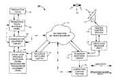
- FIG. 1shows a functional block diagram of a system for airing a broadcast signal over a broadcast network.
- FIG. 2shows a partial cutaway front elevation view of a production truck interface panel of the present invention.
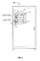
- FIG. 3shows a partial cutaway front elevation view of a demarcation/equipment cabinet of the present invention.
- FIG. 4shows a partial cutaway rear elevation view of a demarcation/equipment cabinet of the present invention.
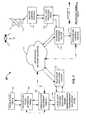
- FIG. 5shows a functional block diagram of a transmission relay circuit of the production truck interface panel of FIG. 2 .
- FIG. 6shows a functional block diagram of a signal sensing and discerning circuit of the transmission relay circuit of FIG. 5 .
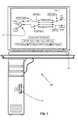
- FIG. 7illustrates a partial cutaway front elevation view of a operations control station of the present invention.
- FIG. 8illustrates a flow diagram of a method of using the present invention.
- FIG. 9illustrates a flow diagram of an alternate method of using the present invention.
- FIG. 1shows an inventive broadcast network 100 for airing a broadcast signal generated by a broadcast signal provider, such as ESPN, FOX, CBS, NBC, and ABC.
- the broadcast network 100preferably includes a production truck 102 , which receives multiple signals from television cameras recording events such as football games, baseball games, hockey games, and other events of interest. Personnel within the production truck 102 make decisions on a continuing basis to determine, which camera shots will be passed on for broadcast.
- the personnel within the production truckpass selected camera shots in the form of a single broadcast signal and four audio signals, or a broadcast signal with embedded audio to a production truck interface panel 104 .
- the production truck interface panel 104provides a multitude of channels for receipt of a number of broadcast signals and their accompanying audio signals, and/or a number of broadcast signals with embedded audio.
- the production truck interface panel 104also provides broadcast signals along with their accompanying audio, or a broadcast signal with embedded audio to the production truck 102 for their own use, or for use in displaying the transmission on a screen at a sporting event such as a JumboTron in a stadium.
- the production truck interface panelUpon receipt of the broadcast signal from the production truck, the production truck interface panel passes for signal onto a demarcation/equipment cabinet 106 .
- the demarcation/equipment cabinet 106determines what type of signal is being received from the production truck 102 , i.e. whether the signal is a NTSC analog video signal, a DS-3 digital video transport signal, an ASI digital video signal, a SDI digital video transport signal, a HD-SDI digital video transport signal, or other broadcast signal.
- the demarcation/equipment cabinet 106processes the signal and hands it off to a television signal receiving and transmission equipment of a local loop provider 108 , such as COX cable.
- the local loop provider 108transports the signal to a television switching center 110 , which converts the television signals into telecommunications signals for transport across an information network backbone 112 .
- the information network backbone 112passes the telecommunications signal to a second television switching center 114 .
- the second television switching center 114converts the telecommunications signals received from the information network backbone 112 back into television signals, which it passes to an operations control station 116 , and a second local loop provider 118 .
- the second local loop provider 118passes the television signals onto a master control station 120 .
- the master control station 120integrates additional information into the television signal, such as commercials, and in a preferred embodiment passes the television signals onto a television broadcast antenna 122 that broadcasts the signal to a satellite transmission station 124 , which broadcasts the signal for mass distribution.
- the master control station 120also passes the integrated television signal back through the second local loop provider 118 , to the second television switching center 114 and onto the information network backbone 112 .
- the information network backbone 112has the ability to deliver the integrated television signal worldwide, as well as back to the first television switching center 110 , the local loop provider 108 , back through the demarcation/equipment cabinet to 106 , the production truck interface panel 104 , and back to the production truck 102 .
- FIG. 2shows a preferred embodiment of the production truck interface panel 104 , provides a bank of telephone service connections 126 , which preferably includes nineteen telephone lines, a T-1 line split into five lines for DSL service, one of which is connected to a modem located within the production truck interface panel 104 , which provides eight DSL output ports 128 . Adjacent the eight DSL output ports 128 , the preferred embodiment provides for digital television signal output channels 130 , and four digital television signal input channels 132 .
- the production truck interface panel 104further provides four additional service panels 134 .
- Each of the additional service panels 134provide a video output port 136 , with accompanying audio output ports 138 for receiving signals from the production truck 102 (of FIG. 1 ), and a video input port 140 along with its accompanying audio input ports 142 .
- both the output port 136 and the input port 140 of each additional service panels 134can accommodate broadcast signals that include NTSC analog video signals, DS-3 digital video transport signals, ASI digital video signals, SDI digital video transport signals, and HD-SDI digital video transport signals.
- FIG. 2further shows the production truck interface panel 104 preferably provides a signal transport circuit 144 (which preferably conducts the broadcast signal through the production truck interface panel 104 , and to the demarcation/equipment cabinet 106 (of FIG. 1 )), a microcontroller 146 , a test signal generator 148 (which in a preferred embodiment generates a NTSC analog video signal), and a switching circuit 150 (which in a preferred embodiment is a failsafe relay).
- the test signal generator 148generates a test signal on an ongoing basis, and when called for a microcontroller 146 , activates the switching circuit 150 to inject a test signal into circuitry housed within the demarcation/equipment cabinet 106 .
- the purpose for injecting the test signal into the systemis to check for continuity between the production truck interface panel 104 and the electronics housed within the demarcation/equipment cabinet 106 .
- the demarcation/equipment cabinet 106shows a front panel 152 of a transmission relay circuit (not shown separately), preferably includes a plurality of BNC connectors 154 , for receiving input signals from the production truck interface panel 104 (of FIG. 2 ).
- BNC connectors 154are shown to be used by the transmission relay circuit, BNC connectors 154 do not impose any limitations on the present invention.
- the BNC connectorshave been selected to enhance an understanding of the present invention by those skilled in the art. Alternate connectors may be used in practicing the invention without deviating from the scope of the invention.
- FIG. 4shows a back panel 156 , of the transmission relay circuit, which preferably provides a graphical representation of the signal paths available for broadcast signals received from the production truck interface panel 104 (of FIG. 2 ).
- a jumper cablesuch as 158
- a jumped cablesuch as 166
- an input signal connector 168 and jumper across to connector 170 of a digital processing path 172is plugged into an input signal connector 168 and jumper across to connector 170 of a digital processing path 172 .
- FIG. 5shows the demarcation/equipment cabinet 106 includes a transmission relay circuit 174 .
- the transmission relay circuit 174preferably includes four signal processing circuits, such as 176 (one shown), accompanied by four broadcast signal sensing and discerning circuits, such as 178 (one shown).
- the transmission relay circuit 174is preferably configured for servicing signals received from the production truck interface panel 104 , and for forwarding those processed signals onto the local loop provider 108 .
- the transmission relay circuit 174preferably further includes four return signal processing circuits, such as 180 (one shown), accompanied by four return signal sensing and discerning circuits such as 182 (one shown).
- the return signal processing circuit 180 , and the return sensing and discerning circuits 182are preferably provided, for servicing signals received from the local loop provider 108 , which are processed, and forwarded to the production truck interface panel 104 for delivery to the production truck 102 .
- the signal processing circuits 176includes the analog path 164 and the digital path 172 .
- the analog path 164is preferably configured for processing NTSC analog video signals
- the digital path 172is preferably configured for processing digital video signals, such as ASI digital video signals, and DS-3, SDI, and HD-SDI video transport signals.
- the analog path 164preferably includes at least an analog video isolation transformer 184 , a video distribution amplifier 186 , and an analog video codec 188 .
- the analog video codec 188outputs a DS-3 analog video transport signal, which is provided to the local loop provider 108 .
- the digital path 172preferably includes a conductive path 190 that bypasses the analog path 164 to pass the signal received from signal transport circuit 144 to the local loop provider 108 .
- the return signal processing circuit 180includes the analog path 192 and the digital path 194 .
- the analog path 192is preferably configured for processing DS-3 digital video signals received from the local loop provider 108 , and converting the received DS-3 digital video signals into NTSC analog video signals for delivery to the production truck interface panel 104 , and onto the production truck 102 .
- the digital path 194is preferably configured for digital video signals, such as ASI digital video signals; and DS-3, SDI, and HD-SDI digital video transport signals.
- the analog path 192preferably includes at least an analog video codec 196 , and a video distribution amplifier 198 .
- the analog video codec 196receives DS-3 analog video transport signal and provides NTSC analog video signals.
- the digital path 194preferably includes a conductive path 200 that bypasses the analog path 192 to pass the signal received from the local loop provider 108 , to the signal transport circuit 144 , and onto the production truck 102 .
- FIG. 5further shows the signal processing circuits 176 preferably further includes an ASI digital video signal generator 202 , and the return signal processing circuit 180 preferably further includes a SDI digital video transport signal generator 204 .
- the signal generatorsare left in a signal generating mode as long as power is supplied to the transmission relay circuit 174 , and are utilized for system testing purposes.
- a microcontroller 206 of the signal sensing and discerning circuit 178activates a relay 208 , which in a preferred embodiment is a failsafe relay, that is a relay the returns to a known state in response to a loss of power.
- a microcontroller 210 of the return signal sensing and discerning circuit 182activates a relay 212 , which in a preferred embodiment is also a failsafe relay. Activation of either the ASI digital video signal generator 202 , or the SDI digital video transport signal generator 204 causes a corresponding test signal to be injected into the broadcast network 100 (of FIG. 1 ).
- the signal sensing and discerning circuit 178further includes a signal detector 214 , which will be covered in greater detail during the discussion of FIG. 6 .
- the signal detector 214is configured to determine what type of broadcast signal is being provided by the production truck 102 . Upon determining which type of signal is being provided by the production truck 102 , the signal detector 214 provides that information to the microcontroller 206 .
- relays 216 and 218which in a preferred embodiment are latching relays, i.e. relays that remain in the state in which they were last placed. Activation of relays 216 and 218 switches in the analog path 164 when the determined signal is an analog type video signal, and switches in digital path 172 when the determined signal is a digital video type signal.
- the signal sensing and discerning circuit 182further includes a signal detector 220 , which will be covered in greater detail during the discussion of FIG. 6 .
- the signal detector 214is configured to determine what type of broadcast signal is being provided by the local loop provider 108 . Upon determining which type of signal is being provided by the local loop provider 108 , the signal detector 220 provides that information to the microcontroller 210 .
- the microcontroller 206activates relays 222 and 224 , which in a preferred embodiment are latching relays. Activation of relays 222 and 224 switches in the analog path 164 when the determined signal is DS-3 digital video transport signal, and switches in digital path 194 when the determined signal is an ASI digital signal, a SDI digital video transport signal, or a HD-SDI digital video transport signal.
- FIG. 6shows the signal sensing and discerning circuit 178 includes an isolation/buffer amplifier 226 , which is selected to appear as a high impedance device to the signal received from the production truck 102 (of FIG. 1 ).
- the isolation/buffer amplifier 226passes the signal received from the production truck 102 to: a NTSC signal analysis circuit 228 , which includes a low bypass filter 230 and a NTSC signal detector 232 ; a DS-3 signal analysis circuit 234 , which includes a band pass filter 236 , and a DS-3 signal detector 238 ; and a combination ASI, SDI, and HD-SDI signal analysis circuit 240 , which includes a line interface 242 , and a combination ASI, SDI, and HD-SDI signal detector 244 .
- the signal sensing and discerning circuit 178further includes the logic circuit 246 .
- the logic circuit 246works in conjunction with the NTSC signal analysis circuit 228 , the DS-3 signal analysis circuit 234 ; and the a combination ASI, SDI, and HD-SDI signal analysis circuit 240 to determine the type of signal that is being received from the production truck 102 .
- the logic circuit 246provides an output signal to a NTSC relay 248 reporting the presence of a NTSC analog video signal type of broadcast signal when the logic circuit 246 receives a signal from the NTSC signal analysis circuit 228 , and no signals from the DS-3 signal analysis circuit 234 , or the combination ASI, SDI, and HD-SDI signal analysis circuit 240 .
- the logic circuit 246provides an output signal to a DS-3 relay 250 reporting the presence of a DS-3 digital video transport signal type of broadcast signal when the logic circuit 246 receives a signal from the DS-3 signal analysis circuit 234 , and no signals from the NTSC signal analysis circuit 228 , or the combination ASI, SDI, and HD-SDI signal analysis circuit 240 .
- the logic circuit 246provides an output signal to an ASI relay 252 reporting the presence of an ASI digital video signal type of broadcast signal when the logic circuit 246 receives an ASI signal from the combination ASI, SDI, and HD-SDI signal analysis circuit 240 , and no signal from the NTSC signal analysis circuit 228 , or the DS-3 signal analysis circuit 234 .
- the logic circuit 246provides an output signal to a SDI relay 254 reporting the presence of a SDI digital video transport signal type of broadcast signal when the logic circuit 246 receives an SDI signal from the combination ASI, SDI, and HD-SDI signal analysis circuit 240 , and no signal from the NTSC signal analysis circuit 228 , or the DS-3 signal analysis circuit 234 .
- the logic circuit 246provides an output signal to a HD-SDI relay 256 reporting the presence of a HD-SDI digital video transport signal type of broadcast signal when the logic circuit 246 receives an HD-SDI signal from the combination ASI, SDI, and HD-SDI signal analysis circuit 240 , and no signal from the NTSC signal analysis circuit 228 , or the DS-3 signal analysis circuit 234 .
- the logic circuit 246provides an output signal to a no signal relay 258 reporting no signal present if no signals are present from the NTSC signal analysis circuit 228 , the DS-3 signal analysis circuit 234 , or the combination ASI, SDI, and HD-SDI signal analysis circuit 240 .
- the logic circuit 246further provide an output signal to the no signal relay 258 reporting no signal present if a signal is present on any two or more of the NTSC signal analysis circuit 228 , the DS-3 signal analysis circuit 234 , and the combination ASI, SDI, and HD-SDI signal analysis circuit 240 .
- FIG. 6further shows: the NTSC signal detector 232 provides a NTSC status line 260 for providing a status signal to the logic circuit 246 , when a NTSC analog video signal is detected; the DS-3 signal detector 238 provides a DS-3 status line 262 for providing a status signal to the logic circuit 246 , when a DS-3 digital video transport signal is detected; and a combination ASI, SDI, and HD-SDI provides an ASI status line 264 for providing a status signal to the logic circuit 246 , when an ASI digital video signal is detected, and a SDI status line 266 for providing a status signal to the logic circuit 246 , when a SDI digital transport signal is detected, and a HD-SDI status line 266 for providing a status signal to the logic circuit 246 , when a HD-SDI digital transport signal is detected.
- the NTSC signal detector 232provides a NTSC status line 260 for providing a status signal to the logic circuit 246 , when a NTSC
- the operations control station 116 shown by FIG. 7preferably includes a microprocessor 270 communicating with the transmission relay circuit 174 (of FIG. 5 ), configuration control software (not shown separately) loaded on the microprocessor 270 , a display 272 responsive to the microprocessor 270 , in a graphical user interface 274 provided by the configuration control software and displayed on the display 272 .
- the graphical user interface 274provides a relay symbol 276 , which when clicked or activated by a user provides an input to the configuration control software, to issue a command to the transmission relay circuit 174 to switch the signal processing circuit 176 (of FIG. 5 ) to a configuration consistent with the type of broadcast signal determined by the signal sensing and discerning circuit 178 .
- FIG. 8shown therein is a flow chart 300 , which depicts a method for broadcasting a signal over a broadcast network (such as 100 ).
- the methodcommences at start process step 302 , and proceeds to process step 304 , with providing a broadcast to a signal transmission relay circuit (such as 174 ), of a demarcation/equipment cabinet (such as 106 ).
- a signal transmission relay circuitsuch as 174
- a demarcation/equipment cabinetsuch as 106
- the type of broadcast signal providedis determined by a signal sensing and discerning circuit (such as 178 ), and at process step 308 , a signal processing circuit (such as 176 ) is reconfigured when the configuration of the signal processing circuit does not support transmission of the determined broadcast signal type.
- the signal sensing and discerning circuitsignals, or transmits a signal identifying the type of broadcast determined by the signal sensing and discerning circuit.
- the processproceeds with process step 312 .
- a pair of connectors(such as 160 and 162 ) of the signal processing circuit that service the determined type of broadcast signal are identified, and at process step 314 , a jumper cable (such as 158 ) is plugged across the pair of identifying connectors to switch in the processing circuit associated with the identified that broadcast signal.
- the signal processing circuitis configured for processing a digital signal when the broadcast signal is determined to be a digital signal.
- the digital signalis transported across the backbone of an information network (such as 112 ).
- an alertis issued to an operations control station (such as 116 ), and/or to a microcontroller (such as 206 ) when a change in state of the transmission relay circuit is detected.
- the change in stateis logged in a memory of the operations control station, and/or the microcontroller, and the process concludes at end process step 324 .
- the processproceeds to process step 326 .
- the processing circuitis configured for processing an analog video signal when the broadcast signal type is determined to be an analog video signal.
- the provided analog video signalis converted to a digital video transport signal, and passed to the backbone of the information network at process step 318 .
- the digital video transport signalis provided by the backbone of the information network to a master control station (such as 120 ) at process step 330 , and the process concludes at end process step 324 .
- process step 332a relay (such as 218 ) is selected for use in configuring the signal processing circuit.
- a relayis activated to connect the provided broadcast signal to the signal processing circuit configured for processing the determined broadcast signal type.
- the activated relayis latched in the process and proceeds to process step 326 .
- the processing circuitis configured for processing an analog video signal when the broadcast signal type is determined to be an analog video signal.
- the provided analog video signalis converted to a digital video transport signal, and passed to the backbone of the information network at process step 318 .
- the digital video transport signalis provided by the backbone of the information network to the master control station at process step 330 , and the process concludes at end process step 324 .
- process step 338where the processing circuit is configured for processing digital video signals in a received broadcast signals are determined to be digital video signals.
- the digital video signalsare passed to the backbone of the information network at process step 318 .
- process step 330the digital video signals are provided to the master control station at process step 330 , and the process concludes at end process step 324 .
- process step 340the type of broadcast signal determined is displayed on a display (such as 272 ), of an operations control station (such as 116 ).
- the operations control stationissues a command to the transmission relay circuit to configure the processing circuit in accordance with the signal type displayed on the display, and the process proceeds to process step 336 .
- the activated relayis latched in the process and proceeds to process step 326 .
- the processing circuitis configured for processing an analog video signal when the broadcast signal type is determined to be an analog video signal.
- the provided analog video signalis converted to a digital video transport signal, and passed to the backbone of the information network at process step 318 .
- the digital video transport signalis provided by the backbone of the information network to the master control station at process step 330 , and the process concludes at end process step 324 .
- process step 338where the processing circuit is configured for processing digital video signals in a received broadcast signals are determined to be digital video signals.
- the digital video signalsare passed to the backbone of the information network at process step 318 .
- process step 330the digital video signals are provided to the master control station at process step 330 , and the process concludes at end process step 324 .
- process step 344the type of broadcast signal determined is displayed on a graphical user interface (GUI) (such as 277 ), of the operations control station.
- GUIgraphical user interface
- process step 346a symbol of a relay (such as 276 ) is activated on the GUI, and the operations control station generates a command to fire the relay (such as relay 216 , and/or relay 218 ) at process step 348 .
- the operations control stationtransmits the command to fire the relay to the transmission relay circuit.
- the microcontroller of the sensing and discerning circuitfires the relay to reconfigure the signal processing circuit, and the process proceeds to process step 336 .
- the activated relayis latched in the process and proceeds to process step 326 .
- the processing circuitis configured for processing an analog video signal when the broadcast signal type is determined to be an analog video signal.
- the provided analog video signalis converted to a digital video transport signal, and passed to the backbone of the information network at process step 318 .
- the digital video transport signalis provided by the backbone of the information network to the master control station at process step 330 , and the process concludes at end process step 324 .
- process step 338where the processing circuit is configured for processing digital video signals in a received broadcast signals are determined to be digital video signals.
- the digital video signalsare passed to the backbone of the information network at process step 318 .
- process step 330the digital video signals are provided to the master control station at process step 330 , an the process concludes at end process step 324 .
- FIG. 9shown therein is a flow chart 400 , which depicts a method for confirming continuity between the demarcation/equipment cabinet broadcasting and a production truck interface panel (such as 104 ).
- the methodcommences at start process step 402 , and proceeds to process step 404 , with generating a broadcast signal with a broadcast signal generator (such as NTSC test signal generator 148 ).
- a broadcast signal generatorsuch as NTSC test signal generator 148
- the generated signalis provided to the demarcation/equipment cabinet.
- the signalis injected into the signal processing circuit ( 176 ) and the signal sensing and discerning circuit ( 178 ).
- the signal type of the injected signalis determined, and the process proceeds to process step 412 .
- the processing circuitis reconfigured, when determined signal type is not supported by the current configuration of the processing circuit.
- the generated broadcast signalis passed from the signal processing circuit to the production truck interface panel.
- the broadcast signalis looped from the production truck interface panel back to the transmission relay circuit.
- the continuity between the demarcation/equipment cabinet broadcasting and a production truck interface panelis confirmed, and the process concludes at end process step 420 .
Landscapes
- Engineering & Computer Science (AREA)
- Signal Processing (AREA)
- Multimedia (AREA)
- Human Computer Interaction (AREA)
- Computer Networks & Wireless Communication (AREA)
- Two-Way Televisions, Distribution Of Moving Picture Or The Like (AREA)
Abstract
Description
Claims (14)
Priority Applications (2)
| Application Number | Priority Date | Filing Date | Title |
|---|---|---|---|
| US15/266,901US9866781B2 (en) | 2006-11-01 | 2016-09-15 | Broadcast method and system |
| US15/864,134US10218931B2 (en) | 2006-11-01 | 2018-01-08 | Broadcast method and system |
Applications Claiming Priority (3)
| Application Number | Priority Date | Filing Date | Title |
|---|---|---|---|
| US11/591,819US7995151B2 (en) | 2006-11-01 | 2006-11-01 | Broadcast method and system |
| US13/205,541US9654237B2 (en) | 2006-11-01 | 2011-08-08 | Broadcast method and system |
| US15/266,901US9866781B2 (en) | 2006-11-01 | 2016-09-15 | Broadcast method and system |
Related Parent Applications (1)
| Application Number | Title | Priority Date | Filing Date |
|---|---|---|---|
| US13/205,541ContinuationUS9654237B2 (en) | 2006-11-01 | 2011-08-08 | Broadcast method and system |
Related Child Applications (1)
| Application Number | Title | Priority Date | Filing Date |
|---|---|---|---|
| US15/864,134ContinuationUS10218931B2 (en) | 2006-11-01 | 2018-01-08 | Broadcast method and system |
Publications (2)
| Publication Number | Publication Date |
|---|---|
| US20170104950A1 US20170104950A1 (en) | 2017-04-13 |
| US9866781B2true US9866781B2 (en) | 2018-01-09 |
Family
ID=39330833
Family Applications (4)
| Application Number | Title | Priority Date | Filing Date |
|---|---|---|---|
| US11/591,819Active2030-04-10US7995151B2 (en) | 2006-11-01 | 2006-11-01 | Broadcast method and system |
| US13/205,541Active2029-02-05US9654237B2 (en) | 2006-11-01 | 2011-08-08 | Broadcast method and system |
| US15/266,901ActiveUS9866781B2 (en) | 2006-11-01 | 2016-09-15 | Broadcast method and system |
| US15/864,134ActiveUS10218931B2 (en) | 2006-11-01 | 2018-01-08 | Broadcast method and system |
Family Applications Before (2)
| Application Number | Title | Priority Date | Filing Date |
|---|---|---|---|
| US11/591,819Active2030-04-10US7995151B2 (en) | 2006-11-01 | 2006-11-01 | Broadcast method and system |
| US13/205,541Active2029-02-05US9654237B2 (en) | 2006-11-01 | 2011-08-08 | Broadcast method and system |
Family Applications After (1)
| Application Number | Title | Priority Date | Filing Date |
|---|---|---|---|
| US15/864,134ActiveUS10218931B2 (en) | 2006-11-01 | 2018-01-08 | Broadcast method and system |
Country Status (4)
| Country | Link |
|---|---|
| US (4) | US7995151B2 (en) |
| EP (1) | EP2080279A4 (en) |
| CA (1) | CA2668427A1 (en) |
| WO (1) | WO2008057787A1 (en) |
Families Citing this family (25)
| Publication number | Priority date | Publication date | Assignee | Title |
|---|---|---|---|---|
| US8072874B2 (en)* | 2007-09-11 | 2011-12-06 | The Directv Group, Inc. | Method and system for switching to an engineering signal processing system from a production signal processing system |
| US7995515B2 (en)* | 2006-10-03 | 2011-08-09 | Viasat, Inc. | Upstream resource optimization |
| US8009236B2 (en) | 2006-11-01 | 2011-08-30 | Level 3 Communications, Llc | Broadcast transmission relay circuit |
| US7995151B2 (en) | 2006-11-01 | 2011-08-09 | Level 3 Communications, Llc | Broadcast method and system |
| JP2008160724A (en)* | 2006-12-26 | 2008-07-10 | Toshiba Corp | Video signal processing apparatus, video signal processing method, and broadcast receiving apparatus |
| US8424044B2 (en)* | 2007-09-11 | 2013-04-16 | The Directv Group, Inc. | Method and system for monitoring and switching between a primary encoder and a back-up encoder in a communication system |
| US9300412B2 (en)* | 2007-09-11 | 2016-03-29 | The Directv Group, Inc. | Method and system for operating a receiving circuit for multiple types of input channel signals |
| US8973058B2 (en) | 2007-09-11 | 2015-03-03 | The Directv Group, Inc. | Method and system for monitoring and simultaneously displaying a plurality of signal channels in a communication system |
| US8170069B2 (en) | 2007-09-11 | 2012-05-01 | The Directv Group, Inc. | Method and system for processing signals from a local collection facility at a signal processing facility |
| US9756290B2 (en) | 2007-09-11 | 2017-09-05 | The Directv Group, Inc. | Method and system for communicating between a local collection facility and a remote facility |
| US20090070829A1 (en)* | 2007-09-11 | 2009-03-12 | The Directv Group, Inc. | Receiving circuit module for receiving and encoding channel signals and method for operating the same |
| US9313457B2 (en) | 2007-09-11 | 2016-04-12 | The Directv Group, Inc. | Method and system for monitoring a receiving circuit module and controlling switching to a back-up receiving circuit module at a local collection facility from a remote facility |
| US8356321B2 (en) | 2007-09-11 | 2013-01-15 | The Directv Group, Inc. | Method and system for monitoring and controlling receiving circuit modules at a local collection facility from a remote facility |
| US8988986B2 (en)* | 2007-09-12 | 2015-03-24 | The Directv Group, Inc. | Method and system for controlling a back-up multiplexer in a local collection facility from a remote facility |
| US8724635B2 (en)* | 2007-09-12 | 2014-05-13 | The Directv Group, Inc. | Method and system for controlling a back-up network adapter in a local collection facility from a remote facility |
| US8479234B2 (en)* | 2007-09-12 | 2013-07-02 | The Directv Group, Inc. | Method and system for monitoring and controlling a local collection facility from a remote facility using an asynchronous transfer mode (ATM) network |
| US7861270B2 (en)* | 2007-09-12 | 2010-12-28 | The Directv Group, Inc. | Method and system for controlling a back-up receiver and encoder in a local collection facility from a remote facility |
| US9049354B2 (en) | 2007-10-30 | 2015-06-02 | The Directv Group, Inc. | Method and system for monitoring and controlling a back-up receiver in local collection facility from a remote facility using an IP network |
| US9037074B2 (en) | 2007-10-30 | 2015-05-19 | The Directv Group, Inc. | Method and system for monitoring and controlling a local collection facility from a remote facility through an IP network |
| US8077706B2 (en)* | 2007-10-31 | 2011-12-13 | The Directv Group, Inc. | Method and system for controlling redundancy of individual components of a remote facility system |
| US9762973B2 (en) | 2008-11-04 | 2017-09-12 | The Directv Group, Inc. | Method and system for operating a receiving circuit module to encode a channel signal into multiple encoding formats |
| US9831971B1 (en) | 2011-04-05 | 2017-11-28 | The Directv Group, Inc. | Method and system for operating a communication system encoded into multiple independently communicated encoding formats |
| US20160037123A1 (en)* | 2014-07-31 | 2016-02-04 | At&T Intellectual Property I, Lp | System and method for input sensing for internet protocol encoders |
| CN105915765A (en)* | 2016-04-26 | 2016-08-31 | 苏州乐聚堂电子科技有限公司 | Program director control system and method |
| US20210314519A1 (en)* | 2020-04-03 | 2021-10-07 | Alpha Opco, LLC | Sporting event television broadcast equipment and system |
Citations (41)
| Publication number | Priority date | Publication date | Assignee | Title |
|---|---|---|---|---|
| EP0488673A2 (en) | 1990-11-30 | 1992-06-03 | Sony Corporation | Matrix switcher apparatus |
| US5345594A (en) | 1991-01-31 | 1994-09-06 | Pioneer Electronic Corporation | Information transmission system retransmitting information signals according to retransmission schedule |
| US5600573A (en) | 1992-12-09 | 1997-02-04 | Discovery Communications, Inc. | Operations center with video storage for a television program packaging and delivery system |
| US5649318A (en) | 1995-03-24 | 1997-07-15 | Terrastar, Inc. | Apparatus for converting an analog c-band broadcast receiver into a system for simultaneously receiving analog and digital c-band broadcast television signals |
| US5659353A (en) | 1995-03-17 | 1997-08-19 | Bell Atlantic Network Services, Inc. | Television distribution system and method |
| US5917553A (en) | 1996-10-22 | 1999-06-29 | Fox Sports Productions Inc. | Method and apparatus for enhancing the broadcast of a live event |
| US6266813B1 (en) | 1998-05-11 | 2001-07-24 | Sony Corporation | Digital broadcasting system and digital broadcasting method |
| US20020059651A1 (en) | 2000-08-18 | 2002-05-16 | Kohzoh Hirata | Multi-broadcast receiving and distributing device |
| US20020178454A1 (en) | 2001-02-14 | 2002-11-28 | Antoine Mark J. | Broadcast television and satellite signal switching system and method for telephony signal insertion |
| US6587154B1 (en) | 1998-09-30 | 2003-07-01 | Micron Technology, Inc. | Method and system for displaying video signals |
| US20030142129A1 (en) | 2002-01-31 | 2003-07-31 | Kleven Michael L. | Content processing and distribution systems and processes |
| US20030206242A1 (en) | 2000-03-24 | 2003-11-06 | Choi Seung Jong | Device and method for converting format in digital TV receiver |
| WO2004008738A1 (en) | 2002-07-12 | 2004-01-22 | Thomson Licensing Sa | Method and device for processing multimedia data |
| US20040066792A1 (en) | 2002-10-03 | 2004-04-08 | Yamaha Corporation | Signal switching apparatus and program |
| US20040151468A1 (en) | 2003-01-24 | 2004-08-05 | Lg Electronics Inc. | Method and apparatus for setting a signal processing mode for reproduction of signals in a disc apparatus |
| US20040161031A1 (en) | 2003-02-13 | 2004-08-19 | Kwentus Alan Y. | Communications signal transcoder |
| US6850250B2 (en) | 2000-08-29 | 2005-02-01 | Sony Corporation | Method and apparatus for a declarative representation of distortion correction for add-on graphics in broadcast video |
| US6870886B2 (en) | 1993-12-15 | 2005-03-22 | Koninklijke Philips Electronics N.V. | Method and apparatus for transcoding a digitally compressed high definition television bitstream to a standard definition television bitstream |
| US20050076134A1 (en) | 2001-05-17 | 2005-04-07 | Gil Bialik | Apparatus and method for multiple rich media formats video broadcasting |
| US6904095B1 (en) | 1998-10-02 | 2005-06-07 | Sony United Kingdom Limited | Digital signal processing and signal format |
| US6907881B2 (en) | 1999-10-14 | 2005-06-21 | The Trustees Of Boston University | Variable peak pressure ventilation method and system |
| US20050169314A1 (en) | 2004-01-30 | 2005-08-04 | Scott Beaudoin | Method for the transmission and distribution of digital television signals |
| US20050212920A1 (en) | 2004-03-23 | 2005-09-29 | Richard Harold Evans | Monitoring system |
| US6965601B1 (en) | 1999-04-16 | 2005-11-15 | Sony Corporation | Data transmitting method and data transmitter |
| US7012964B1 (en) | 1999-04-16 | 2006-03-14 | Sony Corporation | Method and device for data transmission |
| EP1635565A2 (en) | 2004-08-31 | 2006-03-15 | Sony Corporation | Information management apparatus and method, recording medium, as well as program |
| US7046299B1 (en) | 2000-09-29 | 2006-05-16 | Fortel, Dtv | Digital video synchronizer with both decoded digital and undecoded analog outputs |
| US20060130107A1 (en) | 2004-12-15 | 2006-06-15 | Tom Gonder | Method and apparatus for high bandwidth data transmission in content-based networks |
| US20060164546A1 (en) | 2005-01-24 | 2006-07-27 | Sony Corporation | System for delivering contents automatically |
| JP2006203738A (en) | 2005-01-24 | 2006-08-03 | Hitachi Kokusai Electric Inc | Non-linear broadcasting system and conversion device used therefor |
| US7131135B1 (en) | 1998-08-26 | 2006-10-31 | Thomson Licensing | Method for automatically determining the configuration of a multi-input video processing apparatus |
| US7131045B2 (en) | 2003-08-14 | 2006-10-31 | Broadcom Corporation | Systems and methods for scan test access using bond pad test access circuits |
| WO2007082515A1 (en) | 2006-01-23 | 2007-07-26 | Alstom Technology Ltd. | Tube bundle heat exchanger |
| US7256840B2 (en) | 2001-04-06 | 2007-08-14 | Lg Electronics Inc. | Digital television signal translator |
| US7298424B2 (en) | 2001-05-09 | 2007-11-20 | Samsung Electronics Co., Ltd. | Display apparatus and method of controlling the same |
| US7453520B2 (en) | 2003-06-24 | 2008-11-18 | Samsung Electronics Co., Ltd. | Method and apparatus for processing a plurality of input video signals in display device |
| US7690022B2 (en) | 2002-10-02 | 2010-03-30 | Ganesh Basawapatna | Video distribution system for digital and analog subscribers |
| US7728911B2 (en) | 2005-01-26 | 2010-06-01 | Hewlett-Packard Development Company, L.P. | Positively indicating to user whether signal has been detected on each video input |
| US20100312861A1 (en) | 2007-11-30 | 2010-12-09 | Johan Kolhi | Method, network, and node for distributing electronic content in a content distribution network |
| US20110292281A1 (en) | 2006-11-01 | 2011-12-01 | Keener David J | Broadcast method and system |
| US20110310251A1 (en) | 2006-11-01 | 2011-12-22 | Keener David J | Broadcast method and system |
- 2006
- 2006-11-01USUS11/591,819patent/US7995151B2/enactiveActive
- 2007
- 2007-10-25EPEP07863510Apatent/EP2080279A4/ennot_activeCeased
- 2007-10-25CACA002668427Apatent/CA2668427A1/ennot_activeAbandoned
- 2007-10-25WOPCT/US2007/082517patent/WO2008057787A1/enactiveApplication Filing
- 2011
- 2011-08-08USUS13/205,541patent/US9654237B2/enactiveActive
- 2016
- 2016-09-15USUS15/266,901patent/US9866781B2/enactiveActive
- 2018
- 2018-01-08USUS15/864,134patent/US10218931B2/enactiveActive
Patent Citations (42)
| Publication number | Priority date | Publication date | Assignee | Title |
|---|---|---|---|---|
| EP0488673A2 (en) | 1990-11-30 | 1992-06-03 | Sony Corporation | Matrix switcher apparatus |
| US5345594A (en) | 1991-01-31 | 1994-09-06 | Pioneer Electronic Corporation | Information transmission system retransmitting information signals according to retransmission schedule |
| US5600573A (en) | 1992-12-09 | 1997-02-04 | Discovery Communications, Inc. | Operations center with video storage for a television program packaging and delivery system |
| US6870886B2 (en) | 1993-12-15 | 2005-03-22 | Koninklijke Philips Electronics N.V. | Method and apparatus for transcoding a digitally compressed high definition television bitstream to a standard definition television bitstream |
| US5659353A (en) | 1995-03-17 | 1997-08-19 | Bell Atlantic Network Services, Inc. | Television distribution system and method |
| US5649318A (en) | 1995-03-24 | 1997-07-15 | Terrastar, Inc. | Apparatus for converting an analog c-band broadcast receiver into a system for simultaneously receiving analog and digital c-band broadcast television signals |
| US5917553A (en) | 1996-10-22 | 1999-06-29 | Fox Sports Productions Inc. | Method and apparatus for enhancing the broadcast of a live event |
| US20010026319A1 (en) | 1996-10-22 | 2001-10-04 | Fox Sports Productions, Inc. | Method and apparatus for enhancing the broadcast of a live event |
| US6266813B1 (en) | 1998-05-11 | 2001-07-24 | Sony Corporation | Digital broadcasting system and digital broadcasting method |
| US7131135B1 (en) | 1998-08-26 | 2006-10-31 | Thomson Licensing | Method for automatically determining the configuration of a multi-input video processing apparatus |
| US6587154B1 (en) | 1998-09-30 | 2003-07-01 | Micron Technology, Inc. | Method and system for displaying video signals |
| US6904095B1 (en) | 1998-10-02 | 2005-06-07 | Sony United Kingdom Limited | Digital signal processing and signal format |
| US7012964B1 (en) | 1999-04-16 | 2006-03-14 | Sony Corporation | Method and device for data transmission |
| US6965601B1 (en) | 1999-04-16 | 2005-11-15 | Sony Corporation | Data transmitting method and data transmitter |
| US6907881B2 (en) | 1999-10-14 | 2005-06-21 | The Trustees Of Boston University | Variable peak pressure ventilation method and system |
| US20030206242A1 (en) | 2000-03-24 | 2003-11-06 | Choi Seung Jong | Device and method for converting format in digital TV receiver |
| US20020059651A1 (en) | 2000-08-18 | 2002-05-16 | Kohzoh Hirata | Multi-broadcast receiving and distributing device |
| US6850250B2 (en) | 2000-08-29 | 2005-02-01 | Sony Corporation | Method and apparatus for a declarative representation of distortion correction for add-on graphics in broadcast video |
| US7046299B1 (en) | 2000-09-29 | 2006-05-16 | Fortel, Dtv | Digital video synchronizer with both decoded digital and undecoded analog outputs |
| US20020178454A1 (en) | 2001-02-14 | 2002-11-28 | Antoine Mark J. | Broadcast television and satellite signal switching system and method for telephony signal insertion |
| US7256840B2 (en) | 2001-04-06 | 2007-08-14 | Lg Electronics Inc. | Digital television signal translator |
| US7298424B2 (en) | 2001-05-09 | 2007-11-20 | Samsung Electronics Co., Ltd. | Display apparatus and method of controlling the same |
| US20050076134A1 (en) | 2001-05-17 | 2005-04-07 | Gil Bialik | Apparatus and method for multiple rich media formats video broadcasting |
| US20030142129A1 (en) | 2002-01-31 | 2003-07-31 | Kleven Michael L. | Content processing and distribution systems and processes |
| WO2004008738A1 (en) | 2002-07-12 | 2004-01-22 | Thomson Licensing Sa | Method and device for processing multimedia data |
| US7690022B2 (en) | 2002-10-02 | 2010-03-30 | Ganesh Basawapatna | Video distribution system for digital and analog subscribers |
| US20040066792A1 (en) | 2002-10-03 | 2004-04-08 | Yamaha Corporation | Signal switching apparatus and program |
| US20040151468A1 (en) | 2003-01-24 | 2004-08-05 | Lg Electronics Inc. | Method and apparatus for setting a signal processing mode for reproduction of signals in a disc apparatus |
| US20040161031A1 (en) | 2003-02-13 | 2004-08-19 | Kwentus Alan Y. | Communications signal transcoder |
| US7453520B2 (en) | 2003-06-24 | 2008-11-18 | Samsung Electronics Co., Ltd. | Method and apparatus for processing a plurality of input video signals in display device |
| US7131045B2 (en) | 2003-08-14 | 2006-10-31 | Broadcom Corporation | Systems and methods for scan test access using bond pad test access circuits |
| US20050169314A1 (en) | 2004-01-30 | 2005-08-04 | Scott Beaudoin | Method for the transmission and distribution of digital television signals |
| US20050212920A1 (en) | 2004-03-23 | 2005-09-29 | Richard Harold Evans | Monitoring system |
| EP1635565A2 (en) | 2004-08-31 | 2006-03-15 | Sony Corporation | Information management apparatus and method, recording medium, as well as program |
| US20060130107A1 (en) | 2004-12-15 | 2006-06-15 | Tom Gonder | Method and apparatus for high bandwidth data transmission in content-based networks |
| JP2006203738A (en) | 2005-01-24 | 2006-08-03 | Hitachi Kokusai Electric Inc | Non-linear broadcasting system and conversion device used therefor |
| US20060164546A1 (en) | 2005-01-24 | 2006-07-27 | Sony Corporation | System for delivering contents automatically |
| US7728911B2 (en) | 2005-01-26 | 2010-06-01 | Hewlett-Packard Development Company, L.P. | Positively indicating to user whether signal has been detected on each video input |
| WO2007082515A1 (en) | 2006-01-23 | 2007-07-26 | Alstom Technology Ltd. | Tube bundle heat exchanger |
| US20110292281A1 (en) | 2006-11-01 | 2011-12-01 | Keener David J | Broadcast method and system |
| US20110310251A1 (en) | 2006-11-01 | 2011-12-22 | Keener David J | Broadcast method and system |
| US20100312861A1 (en) | 2007-11-30 | 2010-12-09 | Johan Kolhi | Method, network, and node for distributing electronic content in a content distribution network |
Non-Patent Citations (16)
| Title |
|---|
| Canada Examination Report, dated Jul. 16, 2013, Application No. 2,668,191; 4 pgs. |
| Canada Examination Report, dated Jul. 3, 2013, Application No. 2,668,427; 3 pgs. |
| Canadian Examination Report, dated Aug. 11, 2015, Application No. 2,668,191, filed Oct. 25, 2007; 4 pgs. |
| Canadian Examination Report, dated Jul. 29, 2014, Aoplication No. 2,668,191, filed Oct. 25, 2007; 3 pgs. |
| Canadian Examination Report, dated Oct. 6, 2016, Application No. 2,668,191, filed Oct. 25, 2007; 2 pgs. |
| Decision to Refuse a European Patent Application, dated Jun. 3, 2014, Application No. 07863510.9, filed Oct. 25, 2007; 19 pgs. |
| Decision to Refuse a European Patent Application, dated Jun. 6, 2014, Application No. 07863508.3, filed Oct. 25, 2007; 19 pgs. |
| European Examination Report, dated Apr. 8, 2013, Application No. 07863508.3, 9 pgs. |
| European Office Action dated Dec. 20, 2011, EP Appl. No. 07863510.9, 8 pgs. |
| Extended European Search Report dated Nov. 2, 2010,, counterpart App. No. 07863510.9, filed Oct. 25, 2007, 6 pgs. |
| Extended European Search Report, dated Jan. 31, 2012, EP Application No. 07863508.3, 8 pgs. |
| International Search Report and Written Opinion dated Apr. 8, 2008, PCT/US07/82517, filed Oct. 25, 2007, 3 pgs. |
| International Search Report and Written Opinion of the ISA, PCT/US2007/82517, filed Oct. 25, 2007, 10 pgs. |
| International Search Report dated Apr. 8, 2008, PCT/US2007/82515, filed Oct. 25, 2007, 3 pgs. |
| Summons to Attend Oral Proceedings, dated Nov. 5, 2013, European Appl. No. 07863510.9, filed Oct. 25, 2007; 10 pgs. |
| Summons to Attend Oral Proceedings, dated Oct. 15, 2013, Application No. EP07863508.3, filed Oct. 25, 2007; 10 pgs. |
Also Published As
| Publication number | Publication date |
|---|---|
| US20170104950A1 (en) | 2017-04-13 |
| US20110292281A1 (en) | 2011-12-01 |
| CA2668427A1 (en) | 2008-05-15 |
| EP2080279A1 (en) | 2009-07-22 |
| US20080102750A1 (en) | 2008-05-01 |
| US20180131890A1 (en) | 2018-05-10 |
| US7995151B2 (en) | 2011-08-09 |
| EP2080279A4 (en) | 2010-12-01 |
| US10218931B2 (en) | 2019-02-26 |
| WO2008057787A1 (en) | 2008-05-15 |
| WO2008057787A8 (en) | 2009-10-29 |
| US9654237B2 (en) | 2017-05-16 |
Similar Documents
| Publication | Publication Date | Title |
|---|---|---|
| US10218931B2 (en) | Broadcast method and system | |
| US8823878B2 (en) | Broadcast method and system | |
| US9923790B2 (en) | Method and system for monitoring and controlling a video signal network | |
| US5937330A (en) | Settop terminal controlled return path filter for minimizing noise ingress on bidirectional cable systems | |
| US6459793B1 (en) | Cable television setback decoder automatic control | |
| US20010037509A1 (en) | Hybrid wired/wireless video surveillance system | |
| US8990881B2 (en) | Upstream bandwidth conditioning device | |
| US20120044361A1 (en) | Tap Units Having Reverse Path Burst Mode Detection Circuits and Related Methods of Identifying Reverse Path Noise Sources and Reducing Reverse Path Noise Funneling | |
| KR101906300B1 (en) | System and Apparatus for Monitoring Broadcasting Streaming Based on IP | |
| JPS589488A (en) | Reset mechanism of central arithmetic processor of system having plural central arithmetic processors | |
| US20190074904A1 (en) | CATV Point Of Entry Adapter | |
| TW201145907A (en) | CATV entry adapter and method for preventing interference with eMTA equipment from MoCA signals | |
| US20090290070A1 (en) | Systems and methods for remote video production | |
| KR100317858B1 (en) | Home multimedia network architecture | |
| JP2947585B2 (en) | Television receiver with built-in satellite tuner | |
| JPH07303246A (en) | Community reception system and subscriber terminal equipment | |
| EP1843575A1 (en) | Electronic device for receiving and displaying data coming from a multimedia PC and/or from another receiver/decoder | |
| CN103595970A (en) | Video monitoring device and method for rapidly switching analog video and IP video | |
| JPH08256328A (en) | Satellite receiver system with built-in decoder | |
| TW201534069A (en) | Data distribution apparatus |
Legal Events
| Date | Code | Title | Description |
|---|---|---|---|
| AS | Assignment | Owner name:LEVEL 3 COMMUNICATIONS, INC., COLORADO Free format text:ASSIGNMENT OF ASSIGNORS INTEREST;ASSIGNORS:KEENER, DAVID J.;JONES, JOHN S.;WARD, PETER L.;REEL/FRAME:039801/0880 Effective date:20070424 Owner name:LEVEL 3 COMMUNICATIONS, LLC, COLORADO Free format text:ASSIGNMENT OF ASSIGNORS INTEREST;ASSIGNOR:LEVEL 3 COMMUNICATIONS, INC.;REEL/FRAME:039801/0834 Effective date:20070312 | |
| STCF | Information on status: patent grant | Free format text:PATENTED CASE | |
| MAFP | Maintenance fee payment | Free format text:PAYMENT OF MAINTENANCE FEE, 4TH YEAR, LARGE ENTITY (ORIGINAL EVENT CODE: M1551); ENTITY STATUS OF PATENT OWNER: LARGE ENTITY Year of fee payment:4 | |
| AS | Assignment | Owner name:WILMINGTON TRUST, NATIONAL ASSOCIATION, AS COLLATERAL AGENT, MINNESOTA Free format text:NOTICE OF GRANT OF SECURITY INTEREST IN INTELLECTUAL PROPERTY (FIRST LIEN);ASSIGNORS:LEVEL 3 COMMUNICATIONS, LLC;GLOBAL CROSSING TELECOMMUNICATIONS, INC.;REEL/FRAME:069295/0858 Effective date:20241031 Owner name:WILMINGTON TRUST, NATIONAL ASSOCIATION, AS COLLATERAL AGENT, MINNESOTA Free format text:NOTICE OF GRANT OF SECURITY INTEREST IN INTELLECTUAL PROPERTY (SECOND LIEN);ASSIGNORS:LEVEL 3 COMMUNICATIONS, LLC;GLOBAL CROSSING TELECOMMUNICATIONS, INC;REEL/FRAME:069295/0749 Effective date:20241031 | |
| MAFP | Maintenance fee payment | Free format text:PAYMENT OF MAINTENANCE FEE, 8TH YEAR, LARGE ENTITY (ORIGINAL EVENT CODE: M1552); ENTITY STATUS OF PATENT OWNER: LARGE ENTITY Year of fee payment:8 |