US9864415B2 - Multistage friction hinge - Google Patents
Multistage friction hingeDownload PDFInfo
- Publication number
- US9864415B2 US9864415B2US14/755,734US201514755734AUS9864415B2US 9864415 B2US9864415 B2US 9864415B2US 201514755734 AUS201514755734 AUS 201514755734AUS 9864415 B2US9864415 B2US 9864415B2
- Authority
- US
- United States
- Prior art keywords
- hinge
- angle range
- ring
- movement
- cam
- Prior art date
- Legal status (The legal status is an assumption and is not a legal conclusion. Google has not performed a legal analysis and makes no representation as to the accuracy of the status listed.)
- Active, expires
Links
Images


Classifications
- G—PHYSICS
- G06—COMPUTING OR CALCULATING; COUNTING
- G06F—ELECTRIC DIGITAL DATA PROCESSING
- G06F1/00—Details not covered by groups G06F3/00 - G06F13/00 and G06F21/00
- G06F1/16—Constructional details or arrangements
- G06F1/1613—Constructional details or arrangements for portable computers
- G06F1/1633—Constructional details or arrangements of portable computers not specific to the type of enclosures covered by groups G06F1/1615 - G06F1/1626
- G06F1/1675—Miscellaneous details related to the relative movement between the different enclosures or enclosure parts
- G06F1/1681—Details related solely to hinges
- E—FIXED CONSTRUCTIONS
- E05—LOCKS; KEYS; WINDOW OR DOOR FITTINGS; SAFES
- E05D—HINGES OR SUSPENSION DEVICES FOR DOORS, WINDOWS OR WINGS
- E05D11/00—Additional features or accessories of hinges
- E05D11/08—Friction devices between relatively-movable hinge parts
- E05D11/082—Friction devices between relatively-movable hinge parts with substantially radial friction, e.g. cylindrical friction surfaces
- F—MECHANICAL ENGINEERING; LIGHTING; HEATING; WEAPONS; BLASTING
- F16—ENGINEERING ELEMENTS AND UNITS; GENERAL MEASURES FOR PRODUCING AND MAINTAINING EFFECTIVE FUNCTIONING OF MACHINES OR INSTALLATIONS; THERMAL INSULATION IN GENERAL
- F16M—FRAMES, CASINGS OR BEDS OF ENGINES, MACHINES OR APPARATUS, NOT SPECIFIC TO ENGINES, MACHINES OR APPARATUS PROVIDED FOR ELSEWHERE; STANDS; SUPPORTS
- F16M11/00—Stands or trestles as supports for apparatus or articles placed thereon ; Stands for scientific apparatus such as gravitational force meters
- F16M11/02—Heads
- F16M11/04—Means for attachment of apparatus; Means allowing adjustment of the apparatus relatively to the stand
- F16M11/06—Means for attachment of apparatus; Means allowing adjustment of the apparatus relatively to the stand allowing pivoting
- F16M11/10—Means for attachment of apparatus; Means allowing adjustment of the apparatus relatively to the stand allowing pivoting around a horizontal axis
- F—MECHANICAL ENGINEERING; LIGHTING; HEATING; WEAPONS; BLASTING
- F16—ENGINEERING ELEMENTS AND UNITS; GENERAL MEASURES FOR PRODUCING AND MAINTAINING EFFECTIVE FUNCTIONING OF MACHINES OR INSTALLATIONS; THERMAL INSULATION IN GENERAL
- F16M—FRAMES, CASINGS OR BEDS OF ENGINES, MACHINES OR APPARATUS, NOT SPECIFIC TO ENGINES, MACHINES OR APPARATUS PROVIDED FOR ELSEWHERE; STANDS; SUPPORTS
- F16M13/00—Other supports for positioning apparatus or articles; Means for steadying hand-held apparatus or articles
- F16M13/005—Other supports for positioning apparatus or articles; Means for steadying hand-held apparatus or articles integral with the apparatus or articles to be supported
- G—PHYSICS
- G06—COMPUTING OR CALCULATING; COUNTING
- G06F—ELECTRIC DIGITAL DATA PROCESSING
- G06F1/00—Details not covered by groups G06F3/00 - G06F13/00 and G06F21/00
- G06F1/16—Constructional details or arrangements
- G06F1/1613—Constructional details or arrangements for portable computers
- G06F1/1633—Constructional details or arrangements of portable computers not specific to the type of enclosures covered by groups G06F1/1615 - G06F1/1626
- G06F1/1656—Details related to functional adaptations of the enclosure, e.g. to provide protection against EMI, shock, water, or to host detachable peripherals like a mouse or removable expansions units like PCMCIA cards, or to provide access to internal components for maintenance or to removable storage supports like CDs or DVDs, or to mechanically mount accessories
- G06F1/166—Details related to functional adaptations of the enclosure, e.g. to provide protection against EMI, shock, water, or to host detachable peripherals like a mouse or removable expansions units like PCMCIA cards, or to provide access to internal components for maintenance or to removable storage supports like CDs or DVDs, or to mechanically mount accessories related to integrated arrangements for adjusting the position of the main body with respect to the supporting surface, e.g. legs for adjusting the tilt angle
- G—PHYSICS
- G06—COMPUTING OR CALCULATING; COUNTING
- G06F—ELECTRIC DIGITAL DATA PROCESSING
- G06F1/00—Details not covered by groups G06F3/00 - G06F13/00 and G06F21/00
- G06F1/16—Constructional details or arrangements
- G06F1/1613—Constructional details or arrangements for portable computers
- G06F1/1633—Constructional details or arrangements of portable computers not specific to the type of enclosures covered by groups G06F1/1615 - G06F1/1626
- G06F1/1675—Miscellaneous details related to the relative movement between the different enclosures or enclosure parts
- G06F1/1679—Miscellaneous details related to the relative movement between the different enclosures or enclosure parts for locking or maintaining the movable parts of the enclosure in a fixed position, e.g. latching mechanism at the edge of the display in a laptop or for the screen protective cover of a PDA
- E—FIXED CONSTRUCTIONS
- E05—LOCKS; KEYS; WINDOW OR DOOR FITTINGS; SAFES
- E05D—HINGES OR SUSPENSION DEVICES FOR DOORS, WINDOWS OR WINGS
- E05D1/00—Pinless hinges; Substitutes for hinges
- E05D1/04—Pinless hinges; Substitutes for hinges with guide members shaped as circular arcs
- E—FIXED CONSTRUCTIONS
- E05—LOCKS; KEYS; WINDOW OR DOOR FITTINGS; SAFES
- E05D—HINGES OR SUSPENSION DEVICES FOR DOORS, WINDOWS OR WINGS
- E05D11/00—Additional features or accessories of hinges
- E05D11/08—Friction devices between relatively-movable hinge parts
- E05D11/082—Friction devices between relatively-movable hinge parts with substantially radial friction, e.g. cylindrical friction surfaces
- E05D11/084—Friction devices between relatively-movable hinge parts with substantially radial friction, e.g. cylindrical friction surfaces the friction depending on direction of rotation or opening angle of the hinge
- E—FIXED CONSTRUCTIONS
- E05—LOCKS; KEYS; WINDOW OR DOOR FITTINGS; SAFES
- E05D—HINGES OR SUSPENSION DEVICES FOR DOORS, WINDOWS OR WINGS
- E05D11/00—Additional features or accessories of hinges
- E05D11/08—Friction devices between relatively-movable hinge parts
- E05D11/082—Friction devices between relatively-movable hinge parts with substantially radial friction, e.g. cylindrical friction surfaces
- E05D2011/085—Friction devices between relatively-movable hinge parts with substantially radial friction, e.g. cylindrical friction surfaces the friction depending on the opening angle
- E05Y2900/606—
- E—FIXED CONSTRUCTIONS
- E05—LOCKS; KEYS; WINDOW OR DOOR FITTINGS; SAFES
- E05Y—INDEXING SCHEME ASSOCIATED WITH SUBCLASSES E05D AND E05F, RELATING TO CONSTRUCTION ELEMENTS, ELECTRIC CONTROL, POWER SUPPLY, POWER SIGNAL OR TRANSMISSION, USER INTERFACES, MOUNTING OR COUPLING, DETAILS, ACCESSORIES, AUXILIARY OPERATIONS NOT OTHERWISE PROVIDED FOR, APPLICATION THEREOF
- E05Y2999/00—Subject-matter not otherwise provided for in this subclass
- F—MECHANICAL ENGINEERING; LIGHTING; HEATING; WEAPONS; BLASTING
- F16—ENGINEERING ELEMENTS AND UNITS; GENERAL MEASURES FOR PRODUCING AND MAINTAINING EFFECTIVE FUNCTIONING OF MACHINES OR INSTALLATIONS; THERMAL INSULATION IN GENERAL
- F16M—FRAMES, CASINGS OR BEDS OF ENGINES, MACHINES OR APPARATUS, NOT SPECIFIC TO ENGINES, MACHINES OR APPARATUS PROVIDED FOR ELSEWHERE; STANDS; SUPPORTS
- F16M2200/00—Details of stands or supports
- F16M2200/02—Locking means
- F16M2200/021—Locking means for rotational movement
- F16M2200/022—Locking means for rotational movement by friction
- F—MECHANICAL ENGINEERING; LIGHTING; HEATING; WEAPONS; BLASTING
- F16—ENGINEERING ELEMENTS AND UNITS; GENERAL MEASURES FOR PRODUCING AND MAINTAINING EFFECTIVE FUNCTIONING OF MACHINES OR INSTALLATIONS; THERMAL INSULATION IN GENERAL
- F16M—FRAMES, CASINGS OR BEDS OF ENGINES, MACHINES OR APPARATUS, NOT SPECIFIC TO ENGINES, MACHINES OR APPARATUS PROVIDED FOR ELSEWHERE; STANDS; SUPPORTS
- F16M2200/00—Details of stands or supports
- F16M2200/02—Locking means
- F16M2200/021—Locking means for rotational movement
- F16M2200/024—Locking means for rotational movement by positive interaction, e.g. male-female connections
- G—PHYSICS
- G06—COMPUTING OR CALCULATING; COUNTING
- G06F—ELECTRIC DIGITAL DATA PROCESSING
- G06F1/00—Details not covered by groups G06F3/00 - G06F13/00 and G06F21/00
- G06F1/16—Constructional details or arrangements
Definitions
- Mobile computing deviceshave been developed to increase the functionality that is made available to users in a mobile setting. For example, a user may interact with a mobile phone, tablet computer, or other mobile computing device to check email, surf the web, compose texts, interact with applications, and so on.
- mobile computing devicesare configured to be mobile, the devices are typically designed to be used in a handheld manner.
- Traditional ways of adapting mobile devices for other usese.g., on a table or other surface) tend to be awkward and detract from the mobile aesthetic associated with mobile devices.
- a multistage friction hingeis described.
- the described hingeenables a support component to be adjustably attached to an apparatus.
- a hingeincludes different activity stages where movement of the hinge is based on different activity mechanisms.
- the hingeincludes different sets of components that form different friction engines that provide resistance to rotational and/or pivoting movement of the hinge.
- FIG. 1is an illustration of an environment in an example implementation that is operable to employ the techniques described herein in accordance with one or more embodiments.
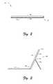
- FIG. 2illustrates an example orientation of an input device in relation to a computing device as covering a display device of the computing device in accordance with one or more embodiments.
- FIG. 3illustrates an example orientation of an input device in relation to a computing device as assuming a typing orientation in accordance with one or more embodiments.
- FIG. 4illustrates an example orientation of a computing device with a support component in accordance with one or more embodiments.
- FIG. 5illustrates an example orientation of a computing device with a support component in accordance with one or more embodiments.
- FIG. 6illustrates an example orientation of a computing device with a support component in accordance with one or more embodiments.
- FIG. 7illustrates an example orientation of a computing device with a support component in accordance with one or more embodiments.
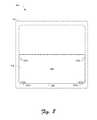
- FIG. 8illustrates an example inner surface of a support component in accordance with one or more embodiments.
- FIG. 9illustrates an example exploded view of a computing device with a support component in accordance with one or more embodiments.
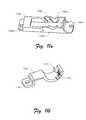
- FIG. 10depicts an isometric view of an example hinge in accordance with one or more embodiments.
- FIG. 11 adepicts an isometric view of a hinge frame in accordance with one or more embodiments.
- FIG. 11 bdepicts an isometric view of a cam in accordance with one or more embodiments.
- FIG. 11 cdepicts a side cross-section view of a cam in accordance with one or more embodiments.
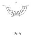
- FIG. 11 ddepicts an isometric view of an upper hinge ring in accordance with one or more embodiments.
- FIG. 11 edepicts an isometric view of a lower surface of an upper hinge ring in accordance with one or more embodiments.
- FIG. 11 fdepicts a side view of a lower hinge ring in accordance with one or more embodiments.
- FIG. 11 gdepicts a side cross-section view of a lower hinge ring in accordance with one or more embodiments.
- FIG. 12depicts a side cross-section view of a hinge in accordance with one or more embodiments.
- FIG. 13depicts a side cross-section view of a hinge in accordance with one or more embodiments.
- FIG. 14depicts a side cross-section view of a hinge in accordance with one or more embodiments.
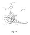
- FIG. 15depicts an isometric side cross-section view of various components of a hinge in accordance with one or more embodiments.
- FIG. 16depicts a partial side view of a computing device with a kickstand opened to a particular position in accordance with one or more embodiments.
- FIG. 17depicts an example implementation scenario that illustrates movement of a kickstand and a hinge in accordance with one or more embodiments.
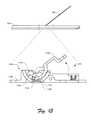
- FIG. 18depicts a side cross section view of an example hinge in accordance with one or more embodiments.
- FIG. 19depicts a partial side view of a computing device with a kickstand opened to a particular position in accordance with one or more embodiments.
- FIG. 20depicts a side cross section view of an example hinge in accordance with one or more embodiments.
- FIG. 21depicts an example implementation scenario for closing a hinge in accordance with one or more embodiments.
- FIG. 22depicts an example implementation scenario for closing a hinge in accordance with one or more embodiments.
- FIG. 23illustrates an example system including various components of an example device that can be implemented as any type of computing device as described with reference to FIGS. 1-22 to implement embodiments of the techniques described herein.
- a multistage friction hingeis described.
- the described hingeenables a support component to be adjustably attached to an apparatus, such as a computing device.
- the hingecan be employed to rotatably attach a kickstand to a mobile computing device.
- the kickstandcan be rotated via the hinge to various positions to provide support for different orientations of the computing device.
- This exampleis not intended to be limiting, however, and the described implementations can be used for hingeable attachment of a wide variety of different components to a wide variety of different apparatus.
- a hingeincludes different activity stages where movement of the hinge is based on different activity mechanisms.
- the hingeincludes different sets of components that form different friction engines and/or friction assemblies that provide resistance to rotational and/or pivoting movement of the hinge.
- a “friction engine” and/or “friction assembly”refers to a set of components that interact to generate frictional force, and thus resistance to movement. Accordingly, hinges described herein provide users with a variety of different angles for component attachment to support a variety of different usage scenarios.
- Various attributes and components of example hinge mechanismsare presented in detail below.
- an example environmentis first described that may employ the techniques described herein.
- Embodiments discussed hereinare not limited to the example environment, and the example environment is not limited to embodiments discussed herein.
- example device orientationsare discussed in accordance with one or more embodiments.
- example hinges for support component attachmentare discussed in accordance with one or more embodiments.
- an example systemis discussed that may implement various techniques described herein.
- FIG. 1is an illustration of an environment 100 in an example implementation that is operable to employ the techniques described herein.
- the illustrated environment 100includes an example of a computing device 102 that is physically and communicatively coupled to an input device 104 via a flexible hinge 106 .
- the computing device 102may be configured in a variety of ways.
- the computing device 102may be configured for mobile use, such as a mobile phone, a tablet computer as illustrated, a wearable device, and so on.
- the computing device 102may range from full resource devices with substantial memory and processor resources, to a low-resource device with limited memory and/or processing resources. An example implementation of the computing device 102 is discussed below with reference to FIG. 23 .
- the computing device 102is illustrated as including an input/output module 108 , which is representative of functionality relating to processing of inputs and rendering outputs of the computing device 102 .
- a variety of different inputsmay be processed by the input/output module 108 , such as inputs relating to functions that correspond to keys of the input device 104 , keys of a virtual keyboard displayed by the display device 110 to identify touch gestures and cause operations to be performed that correspond to the touch gestures that may be recognized through the input device 104 and/or touchscreen functionality of the display device 110 , and so forth.
- the input/output module 108may support a variety of different input techniques by recognizing and leveraging a division between types of inputs including key presses, touch gestures, touchless gestures recognized via a camera functionality of the computing device 102 , and so on.
- the input device 104is configured as having an input portion that includes a keyboard having a QWERTY arrangement of keys and track pad although other arrangements of keys are also contemplated. Further, other non-conventional configurations are also contemplated, such as a game controller, configuration to mimic a musical instrument, and so forth. Thus, the input device 104 and keys incorporated by the input device 104 may assume a variety of different configurations to support a variety of different functionality.
- the input device 104is physically and communicatively coupled to the computing device 102 in this example through use of a flexible hinge 106 .
- the flexible hinge 106is flexible in that rotational movement supported by the hinge is achieved through flexing (e.g., bending) of the material forming the hinge as opposed to mechanical rotation as supported by a pin, although that embodiment is also contemplated. Further, this flexible rotation may be configured to support movement in one or more directions (e.g., vertically in the figure) yet restrict movement in other directions, such as lateral movement of the input device 104 in relation to the computing device 102 . This may be used to support consistent alignment of the input device 104 in relation to the computing device 102 , such as to align sensors used to change power states, application states, and so on.
- a variety of different orientations of the computing device 102are supported.
- rotational movementmay be supported by the flexible hinge 106 such that the input device 104 may be placed against the display device 110 of the computing device 102 and thereby act as a cover as shown in the example orientation 200 of FIG. 2 .
- the input device 104may act to protect the display device 110 of the computing device 102 from harm.
- FIG. 3depicts the computing device 102 in a position 300 .
- the input device 104is laid flat against a surface and the computing device 102 is disposed at an angle to permit viewing of the display device 110 , e.g., such as through use of a kickstand 302 disposed on a rear surface 304 of the computing device 102 .
- the kickstand 302can be employed as a support component to enable a variety of different orientations for the computing device 102 , some of which are described herein. Naturally, a variety of other orientations other than those expressly illustrated and discussed herein are also supported.
- the position 300enables a variety of different usage scenarios, such as by allowing the display device 110 to be viewed and input to be provided to the computing device 102 via the input device 104 . Alternatively or additionally, the position 300 enables a user to interact with a touchscreen of the display device 110 .
- the kickstand 302is rotatably and/or pivotably attached to the rear surface 304 of the computing device along a seam 306 via one or more hinges. Examples of suitable hinges are detailed below and in the accompanying drawings.
- FIG. 4illustrates a position 400 which represents the kickstand 302 in a closed position.
- the kickstand 302forms a portion of the rear surface 304 of the computing device 102 such that the kickstand 302 conforms to a surface contour of the computing device 102 .
- the kickstand 302integrates into the computing device 102 and does not protrude from a plane formed by the rear surface 304 .
- FIG. 5depicts the kickstand 302 in a position 500 .
- the kickstand 302is further opened past the position 300 discussed above to assume the position 500 .
- FIG. 5further depicts different angle ranges that exhibit different movement profiles for the kickstand 302 .
- the kickstand 302includes a closing angle range (“closing range”) 502 , a first friction angle range (“first friction range”) 504 , and a second friction angle range (“second friction range”) 506 .
- the different angle rangesrepresent different angles of the kickstand 302 from a closed position against the rear surface 304 of the computing device 102 , e.g., from the position 400 .
- the closing range 502represents a range of angles at which the kickstand 302 will tend to return to a closed position.
- the kickstand 302includes a magnet along its peripheral edge that holds the kickstand 302 in a closed position based on magnetic attraction between the magnet and a ferromagnetic material on the rear surface 304 of the computing device 102 .
- magnetic attraction and/or gravitational forcewill cause the kickstand 302 to rotate to a closed position relative to the computing device 102 .
- the closing range 502represents a range of zero degrees to thirty degrees, plus/minus ten degrees (0°-30°, +/ ⁇ 10°) from a closed position for the kickstand 302 .
- the first friction range 504represents a range of angles at which the kickstand 302 exhibits a particular torque response. For instance, if a user opens the kickstand 302 past the closing range 502 to an angle within the first friction range 504 and releases the kickstand 302 , the kickstand 302 will remain in the position in which it is released absent further force applied to move the kickstand 302 .
- a hinge that attaches the kickstand 302 to the computing device 102prevents the kickstand 302 from moving from the position at which the kickstand 302 is released unless sufficient force is applied to the kickstand 302 .
- Gravitational force alone and/or the weight of the computing device 102for example, will not displace the kickstand 302 from the position at which it is released.
- the first friction range 504represents a range of thirty one degrees to ninety degrees, plus/minus 10 degrees (31°-90°, +/ ⁇ 10°) from a closed position for the kickstand 302 .
- the second friction range 506represents a range of angles at which the kickstand 302 exhibits a different torque response than for the first friction range 504 . For instance, if a user opens the kickstand 302 past the first friction range 504 to an angle within the second friction range 506 and releases the kickstand 302 , the kickstand 302 will remain in the position in which it is released absent further force applied to move the kickstand 302 .
- a hinge that attaches the kickstand 302 to the computing device 102for example, prevents the kickstand 302 from moving from the position at which the kickstand 302 is released unless sufficient force is applied to the kickstand 302 .
- the second friction range 506represents a range of ninety one degrees to one-hundred eighty degrees, plus/minus 10 degrees (91°-180°, +/ ⁇ 10°) from a closed position for the kickstand 302 .
- resistance to movement (e.g., torque response) of the kickstand 302is greater in the second friction range 506 than in the first friction range 504 .
- torque resistance to movement of the kickstand 302increases. Transitioning from the first friction range 504 to the second friction range 506 , for example, causes a transition in a torque profile for the kickstand 302 .
- this variation in torque response for the kickstand 302is based on a variable torque profile for a hinge that attaches the kickstand 302 to the computing device 102 .
- the position 500 for the kickstand 302represents a maximum position for the kickstand 302 within the first friction range 504 . For instance, opening the kickstand 302 further from the position 500 causes a transition from the first friction range 504 to the second friction range 506 . In at least some implementations, the position 500 represents an angle of ninety degrees plus/minus ten degrees (90°, +/ ⁇ 10°) from a closed position for the kickstand 302 .
- FIG. 6illustrates that the kickstand 302 can be rotated further past the position 500 to a position 600 .
- the position 600represents a position within the second friction range 506 , discussed above.
- the kickstand 302is held in the position 600 via a friction mechanism, examples of which are detailed below.
- the computing device 102is reclined in comparison to previously-discussed orientations, such as the position 500 .
- the position 600presents the display device 110 at a more open angle that supports different usage scenarios. For instance, the position 600 supports use of the computing device 102 in a user's lap, such as during air travel.
- FIG. 6also depicts that the input device 104 is detached from the computing device 102 . As discussed above, the input device 104 is removably attached to the computing device 104 to support a variety of different usage scenarios.
- FIG. 7illustrates that the kickstand 302 can be rotated further away from the rear surface 402 of the computing device 102 to a position 700 .
- the kickstand 302can be rotated further past the position 600 to the position 700 .
- the position 700represents maximum open position for the kickstand 302 .
- the position 700for instance, represents a one hundred and eighty degree (180°) rotation of the kickstand 302 from a closed position.
- the kickstand 302rests against the rear surface 304 of the computing device 102 opposite the closed position 400 depicted in FIG. 4 .
- FIG. 8illustrates a view of an inner surface 800 of the kickstand 302 in accordance with one or more embodiments.
- the kickstand 302is illustrated in the context of an outline of a chassis of the computing device 102 .
- the inner surface 800includes hinge mounts 802 a , 802 b , which function as mounting points for hinge mechanisms that are employed to attach the kickstand 302 to the computing device 102 . Examples of such hinge mechanisms are discussed below.
- the inner surface 800further includes magnets 804 a , 804 b along a lower peripheral edge 806 of the kickstand 302 .
- the magnets 804 a , 804 bhold the kickstand 302 in a closed position and resist opening of the kickstand 302 . Further, magnetic attraction between the magnets 804 a , 804 b and paramagnetic material on the rear surface 304 of the computing device 102 tends to pull the kickstand 302 into a closed position.
- the kickstand 302is released at an open position within the closing range 502 , gravitational force and magnetic attraction between the magnets 804 a , 804 b and paramagnetic material on the rear surface 304 of the computing 102 will cause the kickstand 302 to snap into a closed position.
- hinge mechanismscan be employed for attaching various components in accordance with various embodiments. Some example hinge mechanisms and hinge arrangements are discussed below.
- FIG. 9illustrates an exploded rear view 900 of a chassis 902 of the computing device 102 and the kickstand 302 .
- the rear view 900includes hinges 904 a and 904 b , which are employed to attach the kickstand 302 to the computing device 102 .
- the hinges 904 a , 904 bare installed internally in the computing device 102 , such as via a suitable attachment method and/or device.
- the kickstand 302can be attached to a pivoting portion of the hinges 904 a , 904 b via the hinge mounts 802 a , 802 b .
- attachment to the hinges 904 a , 904 benables the kickstand 302 to pivot between various positions relative to the computing device 102 .
- FIG. 10depicts an isometric view of an example hinge 1000 in accordance with one or more embodiments.
- the hinge 1000for instance, represents an implementation of the hinges 904 a , 904 b discussed above. This is not intended to be limiting, however, and the hinge 1000 can be employed as a hinge for a variety of different components and in a variety of different attachment scenarios.
- the hinge 1000 and its various componentscan be formed using any suitable material and/or combination of materials, such as metals, plastics, polymers, alloys, and so forth.
- the view depicted in FIG. 10represents the hinge 1000 in a closed position, such as the position 400 depicted in FIG. 4 .
- FIGS. 11 a -11 gnow detail some example components of the hinge 1000 .
- FIG. 11 adepicts an isometric view of a hinge frame 1100 in which and/or to which various other components of the hinge 1000 can be disposed and/or attached.
- the hinge frame 1100can be mounted to and/or within a device (e.g., the computing device 102 ) and function as a support structure for other components of the hinge 1000 .
- the hinge frame 1100includes ring guides 1102 a , 1102 b and mounting holes 1104 a , 1104 b .
- the ring guides 1102 a , 1102 brepresent protrusions on the inner surface of the hinge frame 1100 that serve as guiding surfaces for guiding movement of one or more components of the hinge 1000 .
- the mounting holes 1104 a , 1104 brepresents apertures through which a fastening device can be placed to attach the hinge 1000 to an apparatus, such as the computing device 102 .
- the ring guide 1102 aincludes a tab notch 1106 .
- the tab notch 1106represents an indentation in the surface profile of the ring guide 1102 a .
- the tab notch 1106assists in enabling the hinge 1000 to transition between different friction profiles.
- FIG. 11 bdepicts an isometric view of a cam 1108 .
- the cam 1108is positioned at least partially within the hinge frame 1100 .
- the cam 1108includes a mounting hole 1110 , a lock tab 1112 , and a tab spring 1114 .
- the mounting hole 1110represents an aperture through which a fastening device can be placed to attach the cam 1108 to a moveable component, such as the kickstand 302 . For instance, attachment of the kickstand 302 to the cam 1108 enables moveable attachment of the kickstand 302 to the computing device 102 .
- the lock tab 1112enables engagement and disengagement of different friction profiles for the hinge 1000 .
- the tab spring 1114applies biasing force against the lock tab 1112 . Biasing force applied by the tab spring 1114 , for instance, is perpendicular to a longitudinal axis of the cam 1108 .
- FIG. 11 cdepicts a side cross-section view of the cam 1108 in accordance with one or more implementations.
- FIG. 11 cincludes the lock tab 1112 and the tab spring 1114 , introduced above. Further depicted is a spring groove 1116 in a lower surface of the cam 1108 . Further functional details of the spring groove 1116 are presented below.
- FIG. 11 ddepicts an isometric view of an upper hinge ring 1118 in accordance with one or more implementations.
- the upper hinge ring 1118includes ring channels 1120 a , 1120 b and upper ring teeth 1122 .
- the ring guides 1102 a , 1102 bengage within respective instances of the ring channels 1120 a , 1120 b .
- engagement of the ring guides 1102 a , 1102 b with the ring channels 1120 a , 1120 b during movement of the upper hinge ring 1118causes the upper hinge ring 1118 to rotate relative to the hinge frame 1100 .
- the upper ring teeth 1122enable engagement of the upper hinge ring 1118 with one or more other components of the hinge 1000 , discussed in more detail below.
- FIG. 11 edepicts an isometric view of a lower surface 1124 of the upper hinge ring 1118 in accordance with one or more implementations.
- teeth sets 1122 a , 1122 b of the upper ring teeth 1122Positioned along the periphery of the lower surface 1124 are teeth sets 1122 a , 1122 b of the upper ring teeth 1122 , introduced above.
- Formed within the lower surface 1124is an upper ring groove 1126 , which represents a recess within the lower surface 1124 .
- the upper ring groove 1126includes a tab catch 1128 at one end.
- the lock tab 1112 on the cam 1108engages with the tab catch 1128 in certain positions to enable movement of the upper hinge ring 1118 along with the cam 1108 in accordance with one or more implementations.
- FIG. 11 fdepicts a side view of a lower hinge ring 1130 in accordance with one or more implementations.
- the lower hinge ring 1130includes lower ring teeth 1132 , which are positioned to engage with the upper ring teeth of the upper hinge ring 1118 in an assembly of the hinge 1000 .
- the lower hinge ring 1130includes two sets of the lower ring teeth 1132 along opposite edges of the lower hinge ring 1130 .
- respective sets of the lower ring teeth 1132are positioned to engage with different respective sets of the upper ring teeth 1122 to enable the upper hinge ring 1118 and the lower hinge ring 1130 to form an integrated mechanism.
- FIG. 11 gdepicts a side cross-section view of a lower hinge ring 1130 in accordance with one or more implementations. Further depicted are the lower ring teeth 1132 and an inner ring surface 1134 . According to various implementations, the inner ring surface 1134 represents an inside surface of the lower hinge ring 1130 that separates peripheral sets of the lower ring teeth 1132 .
- a lower ring spring 1136is disposed within a recess in the inner ring surface 1134 .
- the lower ring spring 1136for instance, represents a leaf spring or other elastic object fastened within the recess in the inner ring surface 1134 . As further detailed below, the lower ring spring 1136 is positioned to interface with the cam 1108 in one or more positions of the hinge 1000 .
- the components introduced above along with other components of the hinge 1000interact during movement of the hinge 1000 to provide a particular responsiveness profile over different hinge positions.
- openingrefers to a movement of the kickstand 302 and/or the hinge 1000 away from a closed position (e.g., the position 400 ) toward an open position.
- closingrefers to a movement of the kickstand 302 and/or the hinge 1000 from an open position toward a closed position, e.g., toward the position 400 .
- FIG. 12depicts a side cross-section view of the hinge 1000 in accordance with one or more implementations.
- the view depicted in FIG. 12represents the hinge 1000 in a closed position, such as the position 400 of the kickstand 302 relative to the computing device 102 depicted in FIG. 4 .
- This side viewillustrates the hinge frame 1100 , the cam 1108 , the upper hinge ring 1118 , and the lower hinge ring 1130 .
- FIG. 12further depicts a friction bar 1200 disposed on a pivot pin 1202 , and a bar spring 1204 .
- the bar spring 1204is positioned within the hinge frame 1100 such that the bar spring 1204 applies spring force against one end of the friction bar 1200 .
- a contact interface 1206positioned in contact with an outer surface 1208 of the lower hinge ring 1130 .
- spring force from the bar spring 1204presses downward on the friction bar 1200 , which causes the friction bar 1200 to pivot about the pivot pin 1202 such that the contact interface 1206 bears against the outer surface 1208 of the lower hinge ring 1130 .
- Contact between the contact interface 1206 and the outer surface 1208represents a friction interface between the friction bar 1200 and the lower hinge ring 1130 that results in a particular torque profile at certain positions of the hinge 1000 .
- FIG. 12further depicts that the lock tab 1112 of the cam 1108 is positioned within the upper ring groove 1126 of the upper hinge ring 1118 .
- FIG. 13depicts a side cross-section view of the hinge 1000 opened to the position 300 in accordance with one or more implementations. For instance, a user manipulates the kickstand 302 from a closed position relative to the computing device 102 to the position 300 introduced with reference to FIG. 3 .
- This side viewillustrates the hinge frame 1100 , the cam 1108 , the upper hinge ring 1118 , and the lower hinge ring 1130 .
- FIG. 13illustrates that opening the hinge 1000 to the position 300 causes the cam 1108 to engage with and compress the lower ring spring 1136 .
- the depth of the spring groove 1116is such that the cam 1108 does not contact the lower ring spring 1136 .
- the spring groove 1116is tapered such that when the cam 1108 reaches the position 300 , the cam 1108 engages with and compresses the lower ring spring 1136 .
- the point at which the cam 1108 first engages with the lower ring spring 1136represents a transition from the closing range 502 to the first friction range 504 , introduced above.
- interaction between the cam 1108 and the lower ring spring 1136represents a friction engine and/or friction assembly that generates resistance to movement of the cam 1108 relative to the hinge frame 1100 .
- Different components of the hinge 1000represent different friction engines and/or friction assemblies that resist movement of the cam 1108 dependent on a particular angle of the cam 1108 relative to the hinge frame 1100 .
- a depth profile of the spring groove 1116can be altered to provide different torque response profiles.
- the spring groove 1116can be generated with a gradually decreasing depth such that resistance to opening of the kickstand 302 gradually increases due to gradually increasing frictional force between the lower ring spring 1136 and the cam 1108 .
- the spring groove 1116can be generated with a sharply decreasing depth to increase a rate at which frictional forces between the lower ring spring 1136 and the cam 1108 increases.
- FIG. 13further depicts that as the hinge 1000 moves from the closed position to the position 300 , the lock tab 1112 on the cam 1108 moves within the upper ring groove 1126 of the upper hinge ring 1118 .
- FIG. 14depicts a side cross-section view of the hinge 1000 opened to the position 500 in accordance with one or more implementations.
- a useropens the kickstand 302 from the position 300 to the position 500 introduced with reference to FIG. 5 .
- This side viewillustrates the hinge frame 1100 , the cam 1108 , the upper hinge ring 1118 , and the lower hinge ring 1130 .
- the side viewalso illustrates that the upper ring teeth 1122 of the upper hinge ring 1118 engage with the lower ring teeth 1132 of the lower hinge ring 1130 .
- engagement of the upper ring teeth 1122 and the lower ring teeth 1132represents an interlocking mechanism that interlocks the upper hinge ring 1118 with the lower hinge ring 1130 .
- FIG. 14further illustrates that at the position 500 , the lock tab 1112 has reached an end of the upper ring groove 1126 . Accordingly, biasing force from the tab spring 1114 causes the lock tab 1112 to slide into and engage with the tab catch 1128 at the end of the upper ring groove 1126 (introduced in FIG. 11 e ), which is more clearly illustrated in FIG. 15 .
- FIG. 15depicts an isometric side cross-section view of various components of the hinge 1000 opened to the position 500 in accordance with one or more implementations. To aid in understanding, certain components of the hinge 1000 are omitted.
- FIG. 15illustrates that in the position 500 , biasing force from the tab spring 1114 causes the lock tab 1112 to slide into and engage the tab catch 1128 at the end of the upper ring groove 1126 .
- engagement of the lock tab 1112 with the tab catch 1128enables movement of the cam 1108 to cause a corresponding movement of the upper hinge ring 1118 and the lower hinge ring 1130 .
- the position 500represents a transition from the first friction range 504 to the second friction range 506 , introduced above. For instance, opening the hinge 1000 further past the position 500 causes a change in a torque profile for movement of the hinge 1000 according to the second friction range 506 .
- FIG. 16depicts a partial side view of the computing device 102 with the kickstand 302 opened to the position 500 in accordance with one or more implementations. This particular view shows the cam 1108 attached to the kickstand 302 , with the spring groove 1116 in the lower surface of the cam 1108 visible. FIG. 16 further depicts that in the position 500 , the upper hinge ring 1118 and the lower hinge ring 1130 remain positioned within the hinge frame 1100 . As depicted in subsequent figures, further opening of the hinge 1000 past the position 500 causes the upper hinge ring 1118 and the lower hinge ring 1130 to partially pivot outside of the hinge frame 1100 .
- FIG. 17depicts an example implementation scenario 1700 that illustrates movement of the kickstand 302 and the hinge 1000 from the position 300 to the position 500 .
- the upper portion of the scenario 1700depicts a partial view of the computing device 102 with the kickstand 302 and the hinge 1000 in the position 300 .
- the biasing force from the tab spring 1114presses the lock tab 1112 against the ring guide 1102 a.
- the kickstand 302 and the hinge 1000move from the position 300 to the position 500 .
- the tab notch 1106 in the ring guide 1102 aallows biasing force from the tab spring 1114 to move the lock tab 1112 sideways and press the lock tab 1112 into the tab catch 1128 , as depicted in FIG. 15 .
- the tab notch 1106disengages the lock tab 1112 from the tab catch 1128 .
- the lock tab 1112is pushed out of the tab notch 1106 such that the lock tab 1112 moves toward a center of the hinge 1000 and disengages from the tab catch 1128 .
- thisenables the cam 1108 to disengage from the upper hinge ring 1118 and continue from the position 300 toward a closed position.
- FIG. 18depicts a side cross-section view of the hinge 1000 opened to the position 600 in accordance with one or more implementations. For instance, a user opens the kickstand 302 from the position 500 to the position 600 introduced with reference to FIG. 6 .
- This side viewillustrates the hinge frame 1100 , the cam 1108 , the upper hinge ring 1118 , and the lower hinge ring 1130 .
- opening of the hinge 1000 past the position 500causes the upper hinge ring 1118 and the lower hinge ring 1130 to move along with the cam 1108 .
- engagement of the lock tab 1112 with the tab catch 1128 in the upper hinge ring 1118engages the cam 1108 with the upper hinge ring 1118 .
- the upper hinge ring 1118 and the lower hinge ring 1130are engaged with one another via interlocking of their respective ring teeth. Accordingly, opening of the cam 1108 past the position 500 brings the upper hinge ring 1118 and the lower hinge ring 1130 along with the cam 1108 .
- this contact between the contact interface 1206 and the outer surface 1208represents a friction engine and/or friction assembly that determines a torque profile of the hinge 1000 at certain open positions. For instance, movement of the cam 1108 past the position 500 is resisted by the frictional interface between the contact interface 1206 of the friction bar 1200 and the outer surface 1208 of the lower hinge ring 1130 . Opening movement of the cam 1108 past the position 500 , for example, represents a transition from the first friction range 504 to the second friction range 506 .
- torque response in the second friction range 506can be customized by adjusting a length of the friction bar 1200 .
- a shorter friction bar 1200may apply less frictional force against the lower hinge ring 1130 than a longer friction bar.
- torque required to move the cam 1108 in the second friction range 506may be increased by lengthening the portion of the friction bar 1200 between the pivot pin 1202 and the bar spring 1204 , and may be decreased by shortening the same portion of the friction bar 1200 .
- FIG. 19depicts a partial side view of the computing device 102 with the kickstand 302 opened to the position 600 in accordance with one or more implementations.
- This particular viewshows the cam 1108 attached to the kickstand 302 and the lower hinge ring 1130 partially protruding from the hinge frame 1100 .
- movement of the cam 1108 to the position 600causes the lock tab 1112 to drag the upper hinge ring 1118 and the lower hinge ring 1130 along with the cam 1108 .
- FIG. 20depicts a side cross-section view of the hinge 1000 opened to the position 700 in accordance with one or more implementations.
- a useropens the kickstand 302 from the position 600 to the position 700 introduced with reference to FIG. 7 .
- This side viewillustrates the hinge frame 1100 , the cam 1108 , the upper hinge ring 1118 , and the lower hinge ring 1130 .
- FIG. 19further depicts that in the position 700 , the lower hinge ring 1130 and the upper hinge ring 1118 partially protrude from the hinge frame 1100 .
- movement of the cam 1108 from the position 600 to the position 700causes the lock tab 1112 to drag the upper hinge ring 1118 and the lower hinge ring 1130 along with the cam 1108 .
- the position 700represents a maximum open position for the hinge 1000 in at least some implementations.
- resistance of movement of the hinge 1000 from the position 600 to the position 700is according to the second friction range 506 .
- FIG. 21depicts an example implementation scenario 2100 for closing of the hinge 1000 in accordance with one or more implementations.
- the top portion of the scenario 2100illustrates the hinge 1000 in the position 700 .
- the hinge 1000is rotated in a closing direction from the position 700 to the position 600 .
- a usermanipulates the kickstand 302 towards a closing position from the position 700 to the position 600 .
- the upper hinge ring 1118 and the lower hinge ring 1130move along with the cam 1108 .
- engagement of the lock tab 1112 within the tab catch 1128enables the cam 1108 to push the upper hinge ring 1118 and the lower hinge ring 1130 toward a closed position.
- resistance to closing of the cam 1108 from the position 700 to the position 600is based on frictional interaction between the friction bar 1200 and the lower hinge ring 1130 .
- Torque response to closing the cam 1108 from the position 700 to the position 600is based on the second friction range 506 .
- the hinge 1000is rotated in a closing direction from the position 600 to the position 500 .
- a usermanipulates the kickstand 302 towards a closing position from the position 600 to the position 500 .
- the upper hinge ring 1118 and the lower hinge ring 1130move along with the cam 1108 .
- engagement of the lock tab 1112 within the tab catch 1128enables the cam 1108 to push the upper hinge ring 1118 and the lower hinge ring 1130 toward a closed position.
- the scenario 2100then proceeds to a scenario 2200 , discussed below.
- FIG. 22depicts an example implementation scenario 2200 for closing of the hinge 1000 in accordance with one or more implementations.
- the scenario 2200for instance, represents a continuation of the scenario 2100 .
- the top portion of the scenario 2100illustrates that the hinge 1000 is moved in a closing direction from the position 500 to the position 300 .
- moving the cam 1108 in a closing direction from the position 500causes the lock tab 1112 to disengage from the tab catch 1128 .
- a tab notch 1106 in the ring guide 1102 apushes the lock tab 1112 out of the tab catch 1128 such that the lock tab 1112 and thus the cam 1108 disengages from the lower hinge ring 1130 .
- closing of the hinge 1000 past the position 500represents a transition of the hinge 1000 from the second friction range 506 to the first friction range 504 .
- the cam 1108engages with the lower ring spring 1136 .
- frictional interaction between the cam 1108 and the lower ring spring 1136determines a torque response of the hinge 1000 when the hinge 1000 is closed further from the position 500 .
- the hinge 1000is moved in a closing direction from the position 300 to the position 400 , e.g., a closed position.
- the lock tab 1112moves within the upper ring groove 1126 .
- closing the cam 1108 further from the position 300represents a transition from the first friction range 504 to the closing range 502 .
- closing the cam 1108 further from the position 300causes the cam 1108 to disengage from the lower ring spring 1136 such that the kickstand 302 can snap into a closed position.
- dimensions of the spring groove 1116 in the cam 1108are such that when the spring groove 1116 is positioned over the lower ring spring 1136 , the lower ring spring 1136 does not engage with the cam 1108 .
- implementations discussed hereindescribe a multistage friction hinge with a torque profile that varies over different angle ranges. While implementations are discussed with reference to a particular number of friction stages, it is to be appreciated that implementations discussed herein can be employed to construct a hinge with any suitable number of friction stages. It is to be appreciated that usage of the terms “upper,” “lower,” and other relative terms is not to be construed as limiting, and this terminology is simply utilized for purposes of illustration.
- FIG. 23illustrates an example system generally at 2300 that includes an example computing device 2302 that is representative of one or more computing systems and/or devices that may implement the various techniques described herein.
- the computing device 2302represents an implementation of the computing device 102 discussed above.
- the computing device 2302may be, for example, be configured to assume a mobile configuration through use of a housing formed and sized to be grasped and carried by one or more hands of a user, illustrated examples of which include a mobile phone, mobile game and music device, and tablet computer although other examples are also contemplated.
- the computing device 102may be implemented as a wearable device, such as a smart watch, smart glasses, and so forth.
- the example computing device 2302 as illustratedincludes a processing system 2304 , one or more computer-readable media 2306 , and one or more I/O interface 2308 that are communicatively coupled, one to another.
- the computing device 2302may further include a system bus or other data and command transfer system that couples the various components, one to another.
- a system buscan include any one or combination of different bus structures, such as a memory bus or memory controller, a peripheral bus, a universal serial bus, and/or a processor or local bus that utilizes any of a variety of bus architectures.
- a variety of other examplesare also contemplated, such as control and data lines.
- the processing system 2304is representative of functionality to perform one or more operations using hardware. Accordingly, the processing system 2304 is illustrated as including hardware element 2310 that may be configured as processors, functional blocks, and so forth. This may include implementation in hardware as an application specific integrated circuit or other logic device formed using one or more semiconductors.
- the hardware elements 2310are not limited by the materials from which they are formed or the processing mechanisms employed therein.
- processorsmay be comprised of semiconductor(s) and/or transistors (e.g., electronic integrated circuits (ICs)).
- processor-executable instructionsmay be electronically-executable instructions.
- the computer-readable storage media 2306is illustrated as including memory/storage 2312 .
- the memory/storage 2312represents memory/storage capacity associated with one or more computer-readable media.
- the memory/storage component 2312may include volatile media (such as random access memory (RAM)) and/or nonvolatile media (such as read only memory (ROM), Flash memory, optical disks, magnetic disks, and so forth).
- the memory/storage component 2312may include fixed media (e.g., RAM, ROM, a fixed hard drive, and so on) as well as removable media (e.g., Flash memory, a removable hard drive, an optical disc, and so forth).
- the computer-readable media 2306may be configured in a variety of other ways as further described below.
- Input/output interface(s) 2308are representative of functionality to allow a user to enter commands and information to computing device 2302 , and also allow information to be presented to the user and/or other components or devices using various input/output devices.
- input devicesinclude a keyboard, a cursor control device (e.g., a mouse), a microphone, a scanner, touch functionality (e.g., capacitive or other sensors that are configured to detect physical touch), a camera (e.g., which may employ visible or non-visible wavelengths such as infrared frequencies to recognize movement as gestures that do not involve touch), and so forth.
- Examples of output devicesinclude a display device (e.g., a monitor or projector), speakers, a printer, a network card, tactile-response device, and so forth.
- the computing device 2302may be configured in a variety of ways to support user interaction.
- the computing device 2302is further illustrated as being communicatively and physically coupled to an input device 2314 that is physically and communicatively removable from the computing device 2302 .
- an input device 2314that is physically and communicatively removable from the computing device 2302 .
- the input device 2314includes one or more keys 2316 , which may be configured as pressure sensitive keys, mechanically switched keys, and so forth.
- the input device 2314is further illustrated as include one or more modules 2318 that may be configured to support a variety of functionality.
- the one or more modules 2318may be configured to process analog and/or digital signals received from the keys 2316 to determine whether a keystroke was intended, determine whether an input is indicative of resting pressure, support authentication of the input device 2314 for operation with the computing device 2302 , and so on.
- modulesinclude routines, programs, objects, elements, components, data structures, and so forth that perform particular tasks or implement particular abstract data types.
- modulegenerally represent software, firmware, hardware, or a combination thereof.
- the features of the techniques described hereinare platform-independent, meaning that the techniques may be implemented on a variety of commercial computing platforms having a variety of processors.
- Computer-readable mediamay include a variety of media that may be accessed by the computing device 2302 .
- computer-readable mediamay include “computer-readable storage media” and “computer-readable signal media.”
- Computer-readable storage mediamay refer to media and/or devices that enable persistent storage of information in contrast to mere signal transmission, carrier waves, or signals per se. Thus, computer-readable storage media refers to non-signal bearing media.
- the computer-readable storage mediaincludes hardware such as volatile and non-volatile, removable and non-removable media and/or storage devices implemented in a method or technology suitable for storage of information such as computer readable instructions, data structures, program modules, logic elements/circuits, or other data.
- Examples of computer-readable storage mediamay include, but are not limited to, RAM, ROM, EEPROM, flash memory or other memory technology, CD-ROM, digital versatile disks (DVD) or other optical storage, hard disks, magnetic cassettes, magnetic tape, magnetic disk storage or other magnetic storage devices, or other storage device, tangible media, or article of manufacture suitable to store the desired information and which may be accessed by a computer.
- Computer-readable signal mediamay refer to a signal-bearing medium that is configured to transmit instructions to the hardware of the computing device 2302 , such as via a network.
- Signal mediatypically may embody computer readable instructions, data structures, program modules, or other data in a modulated data signal, such as carrier waves, data signals, or other transport
- Signal mediaalso include any information delivery media.
- modulated data signalmeans a signal that has one or more of its characteristics set or changed in such a manner as to encode information in the signal.
- communication mediainclude wired media such as a wired network or direct-wired connection, and wireless media such as acoustic, RF, infrared, and other wireless media.
- hardware elements 2310 and computer-readable media 2306are representative of modules, programmable device logic and/or fixed device logic implemented in a hardware form that may be employed in some embodiments to implement at least some aspects of the techniques described herein, such as to perform one or more instructions.
- Hardwaremay include components of an integrated circuit or on-chip system, an application-specific integrated circuit (ASIC), a field-programmable gate array (FPGA), a complex programmable logic device (CPLD), and other implementations in silicon or other hardware.
- ASICapplication-specific integrated circuit
- FPGAfield-programmable gate array
- CPLDcomplex programmable logic device
- hardwaremay operate as a processing device that performs program tasks defined by instructions and/or logic embodied by the hardware as well as a hardware utilized to store instructions for execution, e.g., the computer-readable storage media described previously.
- software, hardware, or executable modulesmay be implemented as one or more instructions and/or logic embodied on some form of computer-readable storage media and/or by one or more hardware elements 2310 .
- the computing device 2302may be configured to implement particular instructions and/or functions corresponding to the software and/or hardware modules. Accordingly, implementation of a module that is executable by the computing device 2302 as software may be achieved at least partially in hardware, e.g., through use of computer-readable storage media and/or hardware elements 2310 of the processing system 2304 .
- the instructions and/or functionsmay be executable/operable by one or more articles of manufacture (for example, one or more computing devices 2302 and/or processing systems 2304 ) to implement techniques, modules, and examples described herein.
- a deviceincluding: a support movably attached to a rear portion of the device; and at least one multistage friction hinge that moveably attaches a portion of the support to the device, the hinge including: a first angle range in which resistance to movement of the hinge is determined based on engagement of a first friction engine of the hinge; and a second angle range in which resistance to movement of the hinge is determined based on engagement of a second friction engine of the hinge.
- a device as described in one or more of examples 1-8wherein the first angle range represents a first set of open angles of the support relative to the rear portion of the device, and the second angle range represents a second set of open angles of the support relative to the rear portion of the device, wherein the hinge further includes a third angle range that represents a range of angles between a closed position of the support relative to the rear portion of the computing device and the first angle range, and wherein resistance to movement of the hinge in the third angle range is less than resistance to movement of the hinge in the first angle range and the second angle range.
- a hingeincluding: a first friction assembly configured to provide resistance to movement of the hinge across a first angle range; and a second friction assembly configured to provide resistance to movement of the hinge across a second angle range.
- An apparatusincluding: a chassis; a moveable component moveably attached to the chassis; and a multistage friction hinge that moveably attaches the moveable component to the chassis, the multistage friction hinge including: a first friction engine that provides resistance to movement of the moveable component across a first angle range; and a second friction engine that provides resistance to movement of the moveable component across a second angle range.
- the moveable componentincludes a support component that is moveable via the multistage friction hinge to different angles relative to the chassis to support different orientations of the chassis relative to an adjacent surface.
Landscapes
- Engineering & Computer Science (AREA)
- General Engineering & Computer Science (AREA)
- Computer Hardware Design (AREA)
- Theoretical Computer Science (AREA)
- Mechanical Engineering (AREA)
- Human Computer Interaction (AREA)
- Physics & Mathematics (AREA)
- General Physics & Mathematics (AREA)
- Pivots And Pivotal Connections (AREA)
- Telephone Set Structure (AREA)
Abstract
Description
Mobile computing devices have been developed to increase the functionality that is made available to users in a mobile setting. For example, a user may interact with a mobile phone, tablet computer, or other mobile computing device to check email, surf the web, compose texts, interact with applications, and so on.
Because mobile computing devices are configured to be mobile, the devices are typically designed to be used in a handheld manner. Traditional ways of adapting mobile devices for other uses (e.g., on a table or other surface) tend to be awkward and detract from the mobile aesthetic associated with mobile devices.
This Summary is provided to introduce a selection of concepts in a simplified form that are further described below in the Detailed Description. This Summary is not intended to identify key features or essential features of the claimed subject matter, nor is it intended to be used as an aid in determining the scope of the claimed subject matter.
A multistage friction hinge is described. In at least some embodiments, the described hinge enables a support component to be adjustably attached to an apparatus. According to various embodiments, a hinge includes different activity stages where movement of the hinge is based on different activity mechanisms. For instance, the hinge includes different sets of components that form different friction engines that provide resistance to rotational and/or pivoting movement of the hinge.
The detailed description is described with reference to the accompanying figures. In the figures, the left-most digit(s) of a reference number identifies the figure in which the reference number first appears. The use of the same reference numbers in different instances in the description and the figures may indicate similar or identical items. Entities represented in the figures may be indicative of one or more entities and thus reference may be made interchangeably to single or plural forms of the entities in the discussion.
Overview
A multistage friction hinge is described. In at least some implementations, the described hinge enables a support component to be adjustably attached to an apparatus, such as a computing device. For example, the hinge can be employed to rotatably attach a kickstand to a mobile computing device. The kickstand can be rotated via the hinge to various positions to provide support for different orientations of the computing device. This example is not intended to be limiting, however, and the described implementations can be used for hingeable attachment of a wide variety of different components to a wide variety of different apparatus.
According to various implementations, a hinge includes different activity stages where movement of the hinge is based on different activity mechanisms. For instance, the hinge includes different sets of components that form different friction engines and/or friction assemblies that provide resistance to rotational and/or pivoting movement of the hinge. Generally, a “friction engine” and/or “friction assembly” refers to a set of components that interact to generate frictional force, and thus resistance to movement. Accordingly, hinges described herein provide users with a variety of different angles for component attachment to support a variety of different usage scenarios. Various attributes and components of example hinge mechanisms are presented in detail below.
In the following discussion, an example environment is first described that may employ the techniques described herein. Embodiments discussed herein are not limited to the example environment, and the example environment is not limited to embodiments discussed herein. Next, example device orientations are discussed in accordance with one or more embodiments. Following this, example hinges for support component attachment are discussed in accordance with one or more embodiments. Finally, an example system is discussed that may implement various techniques described herein.
Example Environment
While implementations presented herein are discussed in the context of a tablet device, it is to be appreciated that various other types and form factors of devices may be utilized in accordance with the claimed implementations. Thus, thecomputing device 102 may range from full resource devices with substantial memory and processor resources, to a low-resource device with limited memory and/or processing resources. An example implementation of thecomputing device 102 is discussed below with reference toFIG. 23 .
Thecomputing device 102 is illustrated as including an input/output module108, which is representative of functionality relating to processing of inputs and rendering outputs of thecomputing device 102. A variety of different inputs may be processed by the input/output module108, such as inputs relating to functions that correspond to keys of theinput device 104, keys of a virtual keyboard displayed by thedisplay device 110 to identify touch gestures and cause operations to be performed that correspond to the touch gestures that may be recognized through theinput device 104 and/or touchscreen functionality of thedisplay device 110, and so forth. Thus, the input/output module108 may support a variety of different input techniques by recognizing and leveraging a division between types of inputs including key presses, touch gestures, touchless gestures recognized via a camera functionality of thecomputing device 102, and so on.
In the illustrated example, theinput device 104 is configured as having an input portion that includes a keyboard having a QWERTY arrangement of keys and track pad although other arrangements of keys are also contemplated. Further, other non-conventional configurations are also contemplated, such as a game controller, configuration to mimic a musical instrument, and so forth. Thus, theinput device 104 and keys incorporated by theinput device 104 may assume a variety of different configurations to support a variety of different functionality.
As previously described, theinput device 104 is physically and communicatively coupled to thecomputing device 102 in this example through use of aflexible hinge 106. Theflexible hinge 106 is flexible in that rotational movement supported by the hinge is achieved through flexing (e.g., bending) of the material forming the hinge as opposed to mechanical rotation as supported by a pin, although that embodiment is also contemplated. Further, this flexible rotation may be configured to support movement in one or more directions (e.g., vertically in the figure) yet restrict movement in other directions, such as lateral movement of theinput device 104 in relation to thecomputing device 102. This may be used to support consistent alignment of theinput device 104 in relation to thecomputing device 102, such as to align sensors used to change power states, application states, and so on.
Example Device Orientations
According to various embodiments, a variety of different orientations of thecomputing device 102 are supported. For example, rotational movement may be supported by theflexible hinge 106 such that theinput device 104 may be placed against thedisplay device 110 of thecomputing device 102 and thereby act as a cover as shown in theexample orientation 200 ofFIG. 2 . Thus, theinput device 104 may act to protect thedisplay device 110 of thecomputing device 102 from harm.
Theposition 300 enables a variety of different usage scenarios, such as by allowing thedisplay device 110 to be viewed and input to be provided to thecomputing device 102 via theinput device 104. Alternatively or additionally, theposition 300 enables a user to interact with a touchscreen of thedisplay device 110.
According to various implementations, thekickstand 302 is rotatably and/or pivotably attached to therear surface 304 of the computing device along aseam 306 via one or more hinges. Examples of suitable hinges are detailed below and in the accompanying drawings.
Theclosing range 502 represents a range of angles at which thekickstand 302 will tend to return to a closed position. For instance, as illustrated in a subsequent figure, thekickstand 302 includes a magnet along its peripheral edge that holds thekickstand 302 in a closed position based on magnetic attraction between the magnet and a ferromagnetic material on therear surface 304 of thecomputing device 102. In at least some implementations, if a user opens and releases thekickstand 302 at an angle within theclosing range 502, magnetic attraction and/or gravitational force will cause thekickstand 302 to rotate to a closed position relative to thecomputing device 102. In at least some implementations, theclosing range 502 represents a range of zero degrees to thirty degrees, plus/minus ten degrees (0°-30°, +/−10°) from a closed position for thekickstand 302.
Thefirst friction range 504 represents a range of angles at which thekickstand 302 exhibits a particular torque response. For instance, if a user opens thekickstand 302 past theclosing range 502 to an angle within thefirst friction range 504 and releases thekickstand 302, thekickstand 302 will remain in the position in which it is released absent further force applied to move thekickstand 302. A hinge that attaches thekickstand 302 to thecomputing device 102, for example, prevents thekickstand 302 from moving from the position at which thekickstand 302 is released unless sufficient force is applied to thekickstand 302. Gravitational force alone and/or the weight of thecomputing device 102, for example, will not displace thekickstand 302 from the position at which it is released. In at least some implementations, thefirst friction range 504 represents a range of thirty one degrees to ninety degrees, plus/minus 10 degrees (31°-90°, +/−10°) from a closed position for thekickstand 302.
Thesecond friction range 506 represents a range of angles at which thekickstand 302 exhibits a different torque response than for thefirst friction range 504. For instance, if a user opens thekickstand 302 past thefirst friction range 504 to an angle within thesecond friction range 506 and releases thekickstand 302, thekickstand 302 will remain in the position in which it is released absent further force applied to move thekickstand 302. A hinge that attaches thekickstand 302 to thecomputing device 102, for example, prevents thekickstand 302 from moving from the position at which thekickstand 302 is released unless sufficient force is applied to thekickstand 302. Gravitational force alone and/or the weight of thecomputing device 102, for example, will not displace thekickstand 302 from the position at which it is released. In at least some implementations, thesecond friction range 506 represents a range of ninety one degrees to one-hundred eighty degrees, plus/minus 10 degrees (91°-180°, +/−10°) from a closed position for thekickstand 302.
According to various implementations, resistance to movement (e.g., torque response) of thekickstand 302 is greater in thesecond friction range 506 than in thefirst friction range 504. For instance, when a user opens thekickstand 302 past thefirst friction range 504 to thesecond friction range 506, torque resistance to movement of thekickstand 302 increases. Transitioning from thefirst friction range 504 to thesecond friction range 506, for example, causes a transition in a torque profile for thekickstand 302. As detailed below, this variation in torque response for thekickstand 302 is based on a variable torque profile for a hinge that attaches thekickstand 302 to thecomputing device 102.
In at least some implementations, theposition 500 for thekickstand 302 represents a maximum position for thekickstand 302 within thefirst friction range 504. For instance, opening thekickstand 302 further from theposition 500 causes a transition from thefirst friction range 504 to thesecond friction range 506. In at least some implementations, theposition 500 represents an angle of ninety degrees plus/minus ten degrees (90°, +/−10°) from a closed position for thekickstand 302.
In at least some implementations, theposition 700 represents maximum open position for thekickstand 302. Theposition 700, for instance, represents a one hundred and eighty degree (180°) rotation of thekickstand 302 from a closed position. For example, in theposition 700, thekickstand 302 rests against therear surface 304 of thecomputing device 102 opposite theclosed position 400 depicted inFIG. 4 .
Theinner surface 800 further includesmagnets peripheral edge 806 of thekickstand 302. According to various implementations, themagnets kickstand 302 in a closed position and resist opening of thekickstand 302. Further, magnetic attraction between themagnets rear surface 304 of thecomputing device 102 tends to pull thekickstand 302 into a closed position. For instance, if thekickstand 302 is released at an open position within theclosing range 502, gravitational force and magnetic attraction between themagnets rear surface 304 of thecomputing 102 will cause thekickstand 302 to snap into a closed position.
Hinges for Component Attachment
A variety of different hinge mechanisms can be employed for attaching various components in accordance with various embodiments. Some example hinge mechanisms and hinge arrangements are discussed below.
Thekickstand 302 can be attached to a pivoting portion of thehinges hinges kickstand 302 to pivot between various positions relative to thecomputing device 102.
Thehinge frame 1100 includes ring guides1102a,1102band mountingholes hinge frame 1100 that serve as guiding surfaces for guiding movement of one or more components of thehinge 1000. The mountingholes hinge 1000 to an apparatus, such as thecomputing device 102.
Notice that thering guide 1102aincludes atab notch 1106. Generally, thetab notch 1106 represents an indentation in the surface profile of thering guide 1102a. As further detailed below, thetab notch 1106 assists in enabling thehinge 1000 to transition between different friction profiles.
As further detailed below, thelock tab 1112 enables engagement and disengagement of different friction profiles for thehinge 1000. Thetab spring 1114 applies biasing force against thelock tab 1112. Biasing force applied by thetab spring 1114, for instance, is perpendicular to a longitudinal axis of thecam 1108.
According to various implementations, the components introduced above along with other components of thehinge 1000 interact during movement of thehinge 1000 to provide a particular responsiveness profile over different hinge positions.
The following figures discuss different orientations of thehinge 1000, such as based on orientations of thekickstand 302 relative to thecomputing device 102. As discussed herein, “opening” of thekickstand 302 and/or thehinge 1000 refers to a movement of thekickstand 302 and/or thehinge 1000 away from a closed position (e.g., the position400) toward an open position. Further, “closing” of thekickstand 302 and/or thehinge 1000 refers to a movement of thekickstand 302 and/or thehinge 1000 from an open position toward a closed position, e.g., toward theposition 400.
Notice that inFIG. 12 , thelower ring spring 1136 protrudes into thespring groove 1116 in thecam 1108. In the closed position, for example, thelower ring spring 1136 does not contact thecam 1108 and thus does not impede opening of thehinge 1000 from the closed position. As discussed above, thehinge 1000 may be held in the closed position based on other forces, such as magnetic attraction between themagnets chassis 902 of thecomputing device 102.FIG. 12 further depicts that thelock tab 1112 of thecam 1108 is positioned within theupper ring groove 1126 of theupper hinge ring 1118.
Generally, interaction between thecam 1108 and thelower ring spring 1136 represents a friction engine and/or friction assembly that generates resistance to movement of thecam 1108 relative to thehinge frame 1100. Different components of thehinge 1000, for instance, represent different friction engines and/or friction assemblies that resist movement of thecam 1108 dependent on a particular angle of thecam 1108 relative to thehinge frame 1100.
According to various implementations, a depth profile of thespring groove 1116 can be altered to provide different torque response profiles. For instance, thespring groove 1116 can be generated with a gradually decreasing depth such that resistance to opening of thekickstand 302 gradually increases due to gradually increasing frictional force between thelower ring spring 1136 and thecam 1108. Alternatively, thespring groove 1116 can be generated with a sharply decreasing depth to increase a rate at which frictional forces between thelower ring spring 1136 and thecam 1108 increases.
According to various implementations, theposition 500 represents a transition from thefirst friction range 504 to thesecond friction range 506, introduced above. For instance, opening thehinge 1000 further past theposition 500 causes a change in a torque profile for movement of thehinge 1000 according to thesecond friction range 506.
Proceeding to the lower portion of thescenario 1700, thekickstand 302 and thehinge 1000 move from theposition 300 to theposition 500. In moving to theposition 500, thetab notch 1106 in thering guide 1102aallows biasing force from thetab spring 1114 to move thelock tab 1112 sideways and press thelock tab 1112 into thetab catch 1128, as depicted inFIG. 15 .
In a scenario where thekickstand 302 is moved toward a closing position, thetab notch 1106 disengages thelock tab 1112 from thetab catch 1128. For instance, consider that a user closes thekickstand 302 from theposition 500 depicted in the lower portion of thescenario 1700, to theposition 300 depicted in the upper portion of thescenario 1700. Accordingly, thelock tab 1112 is pushed out of thetab notch 1106 such that thelock tab 1112 moves toward a center of thehinge 1000 and disengages from thetab catch 1128. As further detailed below, this enables thecam 1108 to disengage from theupper hinge ring 1118 and continue from theposition 300 toward a closed position.
As shown inFIG. 18 , opening of thehinge 1000 past theposition 500 causes theupper hinge ring 1118 and thelower hinge ring 1130 to move along with thecam 1108. For instance, engagement of thelock tab 1112 with thetab catch 1128 in theupper hinge ring 1118 engages thecam 1108 with theupper hinge ring 1118. Further, theupper hinge ring 1118 and thelower hinge ring 1130 are engaged with one another via interlocking of their respective ring teeth. Accordingly, opening of thecam 1108 past theposition 500 brings theupper hinge ring 1118 and thelower hinge ring 1130 along with thecam 1108.
As discussed above, spring force from thebar spring 1204 presses downward on thefriction bar 1200, which causes thefriction bar 1200 to pivot about thepivot pin 1202 such that thecontact interface 1206 bears against theouter surface 1208 of thelower hinge ring 1130. According to various implementations, this contact between thecontact interface 1206 and theouter surface 1208 represents a friction engine and/or friction assembly that determines a torque profile of thehinge 1000 at certain open positions. For instance, movement of thecam 1108 past theposition 500 is resisted by the frictional interface between thecontact interface 1206 of thefriction bar 1200 and theouter surface 1208 of thelower hinge ring 1130. Opening movement of thecam 1108 past theposition 500, for example, represents a transition from thefirst friction range 504 to thesecond friction range 506.
According to various implementations, torque response in thesecond friction range 506 can be customized by adjusting a length of thefriction bar 1200. For instance, ashorter friction bar 1200 may apply less frictional force against thelower hinge ring 1130 than a longer friction bar. Thus, torque required to move thecam 1108 in thesecond friction range 506 may be increased by lengthening the portion of thefriction bar 1200 between thepivot pin 1202 and thebar spring 1204, and may be decreased by shortening the same portion of thefriction bar 1200.
As discussed above, theposition 700 represents a maximum open position for thehinge 1000 in at least some implementations. Generally, resistance of movement of thehinge 1000 from theposition 600 to theposition 700 is according to thesecond friction range 506.
Further, resistance to closing of thecam 1108 from theposition 700 to theposition 600 is based on frictional interaction between thefriction bar 1200 and thelower hinge ring 1130. Torque response to closing thecam 1108 from theposition 700 to theposition 600, for example, is based on thesecond friction range 506.
Proceeding from the center portion to the lower portion of thescenario 2100, thehinge 1000 is rotated in a closing direction from theposition 600 to theposition 500. For instance, a user manipulates thekickstand 302 towards a closing position from theposition 600 to theposition 500. As illustrated, theupper hinge ring 1118 and thelower hinge ring 1130 move along with thecam 1108. For instance, engagement of thelock tab 1112 within thetab catch 1128 enables thecam 1108 to push theupper hinge ring 1118 and thelower hinge ring 1130 toward a closed position. Thescenario 2100 then proceeds to ascenario 2200, discussed below.
According to various implementations, closing of thehinge 1000 past theposition 500 represents a transition of thehinge 1000 from thesecond friction range 506 to thefirst friction range 504. For instance, at theposition 500, thecam 1108 engages with thelower ring spring 1136. Thus, frictional interaction between thecam 1108 and thelower ring spring 1136 determines a torque response of thehinge 1000 when thehinge 1000 is closed further from theposition 500.
Continuing to the lower portion of the scenario, thehinge 1000 is moved in a closing direction from theposition 300 to theposition 400, e.g., a closed position. During movement to theposition 400, thelock tab 1112 moves within theupper ring groove 1126. According to various implementations, closing thecam 1108 further from theposition 300 represents a transition from thefirst friction range 504 to theclosing range 502. For instance, closing thecam 1108 further from theposition 300 causes thecam 1108 to disengage from thelower ring spring 1136 such that thekickstand 302 can snap into a closed position. As detailed above, dimensions of thespring groove 1116 in thecam 1108 are such that when thespring groove 1116 is positioned over thelower ring spring 1136, thelower ring spring 1136 does not engage with thecam 1108.
Thus, implementations discussed herein describe a multistage friction hinge with a torque profile that varies over different angle ranges. While implementations are discussed with reference to a particular number of friction stages, it is to be appreciated that implementations discussed herein can be employed to construct a hinge with any suitable number of friction stages. It is to be appreciated that usage of the terms “upper,” “lower,” and other relative terms is not to be construed as limiting, and this terminology is simply utilized for purposes of illustration.
Having discussed some example hinge positions and configurations, consider now an example system that can employ the example hinge configurations in accordance with one or more implementations.
Example System and Device
Theexample computing device 2302 as illustrated includes aprocessing system 2304, one or more computer-readable media 2306, and one or more I/O interface 2308 that are communicatively coupled, one to another. Although not shown, thecomputing device 2302 may further include a system bus or other data and command transfer system that couples the various components, one to another. A system bus can include any one or combination of different bus structures, such as a memory bus or memory controller, a peripheral bus, a universal serial bus, and/or a processor or local bus that utilizes any of a variety of bus architectures. A variety of other examples are also contemplated, such as control and data lines.
Theprocessing system 2304 is representative of functionality to perform one or more operations using hardware. Accordingly, theprocessing system 2304 is illustrated as including hardware element2310 that may be configured as processors, functional blocks, and so forth. This may include implementation in hardware as an application specific integrated circuit or other logic device formed using one or more semiconductors. The hardware elements2310 are not limited by the materials from which they are formed or the processing mechanisms employed therein. For example, processors may be comprised of semiconductor(s) and/or transistors (e.g., electronic integrated circuits (ICs)). In such a context, processor-executable instructions may be electronically-executable instructions.
The computer-readable storage media 2306 is illustrated as including memory/storage 2312. The memory/storage 2312 represents memory/storage capacity associated with one or more computer-readable media. The memory/storage component 2312 may include volatile media (such as random access memory (RAM)) and/or nonvolatile media (such as read only memory (ROM), Flash memory, optical disks, magnetic disks, and so forth). The memory/storage component 2312 may include fixed media (e.g., RAM, ROM, a fixed hard drive, and so on) as well as removable media (e.g., Flash memory, a removable hard drive, an optical disc, and so forth). The computer-readable media 2306 may be configured in a variety of other ways as further described below.
Input/output interface(s)2308 are representative of functionality to allow a user to enter commands and information tocomputing device 2302, and also allow information to be presented to the user and/or other components or devices using various input/output devices. Examples of input devices include a keyboard, a cursor control device (e.g., a mouse), a microphone, a scanner, touch functionality (e.g., capacitive or other sensors that are configured to detect physical touch), a camera (e.g., which may employ visible or non-visible wavelengths such as infrared frequencies to recognize movement as gestures that do not involve touch), and so forth. Examples of output devices include a display device (e.g., a monitor or projector), speakers, a printer, a network card, tactile-response device, and so forth. Thus, thecomputing device 2302 may be configured in a variety of ways to support user interaction.
Thecomputing device 2302 is further illustrated as being communicatively and physically coupled to aninput device 2314 that is physically and communicatively removable from thecomputing device 2302. In this way, a variety of different input devices may be coupled to thecomputing device 2302 having a wide variety of configurations to support a wide variety of functionality. In this example, theinput device 2314 includes one ormore keys 2316, which may be configured as pressure sensitive keys, mechanically switched keys, and so forth.
Theinput device 2314 is further illustrated as include one ormore modules 2318 that may be configured to support a variety of functionality. The one ormore modules 2318, for instance, may be configured to process analog and/or digital signals received from thekeys 2316 to determine whether a keystroke was intended, determine whether an input is indicative of resting pressure, support authentication of theinput device 2314 for operation with thecomputing device 2302, and so on.
Various techniques may be described herein in the general context of software, hardware elements, or program modules. Generally, such modules include routines, programs, objects, elements, components, data structures, and so forth that perform particular tasks or implement particular abstract data types. The terms “module,” “functionality,” and “component” as used herein generally represent software, firmware, hardware, or a combination thereof. The features of the techniques described herein are platform-independent, meaning that the techniques may be implemented on a variety of commercial computing platforms having a variety of processors.
An implementation of the described modules and techniques may be stored on or transmitted across some form of computer-readable media. The computer-readable media may include a variety of media that may be accessed by thecomputing device 2302. By way of example, and not limitation, computer-readable media may include “computer-readable storage media” and “computer-readable signal media.”
“Computer-readable storage media” may refer to media and/or devices that enable persistent storage of information in contrast to mere signal transmission, carrier waves, or signals per se. Thus, computer-readable storage media refers to non-signal bearing media. The computer-readable storage media includes hardware such as volatile and non-volatile, removable and non-removable media and/or storage devices implemented in a method or technology suitable for storage of information such as computer readable instructions, data structures, program modules, logic elements/circuits, or other data. Examples of computer-readable storage media may include, but are not limited to, RAM, ROM, EEPROM, flash memory or other memory technology, CD-ROM, digital versatile disks (DVD) or other optical storage, hard disks, magnetic cassettes, magnetic tape, magnetic disk storage or other magnetic storage devices, or other storage device, tangible media, or article of manufacture suitable to store the desired information and which may be accessed by a computer.
“Computer-readable signal media” may refer to a signal-bearing medium that is configured to transmit instructions to the hardware of thecomputing device 2302, such as via a network. Signal media typically may embody computer readable instructions, data structures, program modules, or other data in a modulated data signal, such as carrier waves, data signals, or other transport Signal media also include any information delivery media. The term “modulated data signal” means a signal that has one or more of its characteristics set or changed in such a manner as to encode information in the signal. By way of example, and not limitation, communication media include wired media such as a wired network or direct-wired connection, and wireless media such as acoustic, RF, infrared, and other wireless media.
As previously described, hardware elements2310 and computer-readable media 2306 are representative of modules, programmable device logic and/or fixed device logic implemented in a hardware form that may be employed in some embodiments to implement at least some aspects of the techniques described herein, such as to perform one or more instructions. Hardware may include components of an integrated circuit or on-chip system, an application-specific integrated circuit (ASIC), a field-programmable gate array (FPGA), a complex programmable logic device (CPLD), and other implementations in silicon or other hardware. In this context, hardware may operate as a processing device that performs program tasks defined by instructions and/or logic embodied by the hardware as well as a hardware utilized to store instructions for execution, e.g., the computer-readable storage media described previously.
Combinations of the foregoing may also be employed to implement various techniques described herein. Accordingly, software, hardware, or executable modules may be implemented as one or more instructions and/or logic embodied on some form of computer-readable storage media and/or by one or more hardware elements2310. Thecomputing device 2302 may be configured to implement particular instructions and/or functions corresponding to the software and/or hardware modules. Accordingly, implementation of a module that is executable by thecomputing device 2302 as software may be achieved at least partially in hardware, e.g., through use of computer-readable storage media and/or hardware elements2310 of theprocessing system 2304. The instructions and/or functions may be executable/operable by one or more articles of manufacture (for example, one ormore computing devices 2302 and/or processing systems2304) to implement techniques, modules, and examples described herein.
Implementations discussed herein include:
A device including: a support movably attached to a rear portion of the device; and at least one multistage friction hinge that moveably attaches a portion of the support to the device, the hinge including: a first angle range in which resistance to movement of the hinge is determined based on engagement of a first friction engine of the hinge; and a second angle range in which resistance to movement of the hinge is determined based on engagement of a second friction engine of the hinge.
A device as described in example 1, wherein the first angle range represents a first set of angles of the support relative to the rear portion of the device, and the second angle range represents a second set of angles of the support relative to the rear portion of the device, and wherein the second set of angles is different than the first set of angles.
A device as described in one or more of examples 1 or 2, wherein the first angle range represents a first set of open angles of the support relative to the rear portion of the device, and the second angle range represents a second set of open angles of the support relative to the rear portion of the device, and wherein the second set of angles includes greater open angles than the first set of angles.
A device as described in one or more of examples 1-3, wherein movement of the hinge from the first angle range to the second angle range causes a transition from the first friction engine to the second friction engine.
A device as described in one or more of examples 1-4, wherein opening of the hinge from the first angle range to the second angle range causes a transition from the first friction engine to the second friction engine.
A device as described in one or more of examples 1-5, wherein closing of the hinge from the second angle range to the first angle range causes a transition from the second friction engine to the first friction engine.
A device as described in one or more of examples 1-6, wherein resistance to movement of the hinge is greater in the second angle range than in the first angle range.
A device as described in one or more of examples 1-7, wherein the first friction engine is based on spring force from a first spring of the hinge, and wherein the second friction engine is based on spring force from a second spring of the hinge.
A device as described in one or more of examples 1-8, wherein the first angle range represents a first set of open angles of the support relative to the rear portion of the device, and the second angle range represents a second set of open angles of the support relative to the rear portion of the device, wherein the hinge further includes a third angle range that represents a range of angles between a closed position of the support relative to the rear portion of the computing device and the first angle range, and wherein resistance to movement of the hinge in the third angle range is less than resistance to movement of the hinge in the first angle range and the second angle range.
A hinge including: a first friction assembly configured to provide resistance to movement of the hinge across a first angle range; and a second friction assembly configured to provide resistance to movement of the hinge across a second angle range.
A hinge as described in example 10, wherein the second friction assembly provides greater resistance to movement of the hinge than does the first friction assembly.
A hinge as described in one or more of examples 10 or 11, wherein the first friction assembly is based on frictional interaction between a first set of components of the hinge, and wherein the second friction assembly is based on frictional interaction between a second set of components of the hinge, the second set of components being different than the first set of components.
A hinge as described in one or more of examples 10-12, wherein the hinge includes: a hinge frame including at least one ring guide; an upper hinge ring slidably engaged with the at least one ring guide; a lower hinge ring interlocked with the upper hinge ring and including a lower ring spring disposed on an inner surface of the lower hinge ring; and a cam positioned at least in part between the upper hinge ring and the lower hinge ring such that when the hinge is positioned within the first angle range, the cam engages with the lower ring spring to form at least a part of the first friction assembly.
A hinge as described in one or more of examples 10-13, wherein the hinge includes: a hinge frame including at least one ring guide; an upper hinge ring slidably engaged with the at least one ring guide; a lower hinge ring interlocked with the upper hinge ring; a friction bar pivotably attached to the hinge frame and positioned such that a first portion of the friction bar is in contact with the lower hinge ring; a bar spring disposed within the hinge frame to apply biasing force to a second portion of the friction bar to cause the first portion of the friction bar to bear against the lower hinge ring; and a cam positioned at least in part between the upper hinge ring and the lower hinge ring such that when the cam is positioned within the second angle range, frictional force applied by the first portion of the friction bar against the lower hinge ring resists movement of the cam relative to the hinge frame and forms at least a part of the second friction assembly.
A hinge as described in one or more of examples 10-14, wherein the hinge includes: a hinge frame including at least one ring guide; an upper hinge ring slidably engaged with the at least one ring guide; a lower hinge ring interlocked with the upper hinge ring; a friction bar pivotably attached to the hinge frame and positioned such that a first portion of the friction bar is in contact with the lower hinge ring; a bar spring disposed within the hinge frame to apply biasing force to a second portion of the friction bar to cause the first portion of the friction bar to bear against the lower hinge ring; and a cam positioned at least in part between the upper hinge ring and the lower hinge ring and including a spring biased locking tab such that when the cam transitions from the first angle range to the second angle range, the locking tab engages with the upper hinge ring and movement of the cam within the second angle range causes corresponding movement of the upper hinge ring and the lower hinge ring, and frictional force applied by the first portion of the friction bar against the lower hinge ring resists movement of the cam relative to the hinge frame and forms at least a part of the second friction assembly.
An apparatus including: a chassis; a moveable component moveably attached to the chassis; and a multistage friction hinge that moveably attaches the moveable component to the chassis, the multistage friction hinge including: a first friction engine that provides resistance to movement of the moveable component across a first angle range; and a second friction engine that provides resistance to movement of the moveable component across a second angle range.
An apparatus as described in example 16, wherein the moveable component includes a support component that is moveable via the multistage friction hinge to different angles relative to the chassis to support different orientations of the chassis relative to an adjacent surface.
An apparatus as described in one or more of examples 16 or 17, wherein the apparatus includes a computing device, the chassis includes a display device, and wherein the moveable component includes a support component that is moveable via the multistage friction hinge to support different viewing angles for the display device.
An apparatus as described in one or more of examples 16-18, wherein the second friction engine provides greater resistance to movement of the moveable component in the second angle range than the first friction engine in the first angle range.
An apparatus as described in one or more of examples 16-19, wherein movement of the moveable component from the first angle range to the second angle range causes the multistage friction hinge to transition from the first friction engine to the second friction engine.
Conclusion
Although the example implementations have been described in language specific to structural features and/or methodological acts, it is to be understood that the implementations defined in the appended claims is not necessarily limited to the specific features or acts described. Rather, the specific features and acts are disclosed as example forms of implementing the claimed features.
Claims (20)
1. A device comprising:
a support movably attached to a rear portion of the device; and
at least one multistage friction hinge that moveably attaches a portion of the support to the device, the hinge including:
a first angle range in which resistance to movement of the hinge is determined based on engagement of a first friction engine of the hinge; and
a second angle range in which resistance to movement of the hinge is determined based on engagement of a second friction engine of the hinge, the hinge further including:
a hinge frame;
an upper hinge ring slidably engaged with the hinge frame;
a lower hinge ring interlocked with the upper hinge ring; and
a cam attached to the support and positioned at least in part between the upper hinge ring and the lower hinge ring, the cam including a spring biased locking tab such that when the cam transitions from the first angle range to the second angle range, the locking tab engages with the upper hinge ring and movement of the cam within the second angle range causes corresponding movement of the upper hinge ring and the lower hinge ring to form at least a part of the second friction engine.
2. A device as described inclaim 1 , wherein the first angle range represents a first set of angles of the support relative to the rear portion of the device, and the second angle range represents a second set of angles of the support relative to the rear portion of the device, and wherein the second set of angles is different than the first set of angles.
3. A device as described inclaim 1 , wherein the first angle range represents a first set of open angles of the support relative to the rear portion of the device, and the second angle range represents a second set of open angles of the support relative to the rear portion of the device, and wherein the second set of angles includes greater open angles than the first set of angles.
4. A device as described inclaim 1 , wherein movement of the hinge from the first angle range to the second angle range causes a transition from the first friction engine to the second friction engine.
5. A device as described inclaim 1 , wherein opening of the hinge from the first angle range to the second angle range causes a transition from the first friction engine to the second friction engine.
6. A device as described inclaim 1 , wherein closing of the hinge from the second angle range to the first angle range causes a transition from the second friction engine to the first friction engine.
7. A device as described inclaim 1 , wherein resistance to movement of the hinge is greater in the second angle range than in the first angle range.
8. A device as described inclaim 1 , wherein the first friction engine is based on spring force from a first spring of the hinge, and wherein the second friction engine is based on spring force from a second spring of the hinge.
9. A device as described inclaim 1 , wherein the first angle range represents a first set of open angles of the support relative to the rear portion of the device, and the second angle range represents a second set of open angles of the support relative to the rear portion of the device, wherein the hinge further includes a third angle range that represents a range of angles between a closed position of the support relative to the rear portion of the device and the first angle range, and wherein resistance to movement of the hinge in the third angle range is less than resistance to movement of the hinge in the first angle range and the second angle range.
10. A device comprising:
a support movably attached to a rear portion of the device; and
a hinge that moveably attaches a portion of the support to the device, the hinge including:
a hinge frame;
an upper hinge ring slidably engaged with the hinge frame;
a lower hinge ring interlocked with the upper hinge ring; and
a cam attached to the support and positioned at least in part between the upper hinge ring and the lower hinge ring, the cam including a spring biased locking tab such that when the cam transitions from a first angle range of the hinge to a second angle range of the hinge, the locking tab engages with the upper hinge ring and movement of the cam within the second angle range causes corresponding movement of the upper hinge ring and the lower hinge ring from the first angle range to the second angle range.
11. A device as described inclaim 10 , wherein the support is configured to support the device at different positions relative to an adjacent surface.
12. A device as described inclaim 10 , wherein the first angle range represents a first set of angles of the support relative to the rear portion of the device, and the second angle range represents a second set of angles of the support relative to the rear portion of the computing device, and wherein the second set of angles is different than the first set of angles.
13. A device as described inclaim 10 , wherein resistance to movement of the hinge is greater in the second angle range than in the first angle range.
14. A device as described inclaim 10 , wherein resistance to movement of the hinge increases as the hinge moves from the first angle range to the second angle range.
15. A device as described inclaim 10 , wherein resistance to movement of the hinge in the first angle range is based on spring force from a first spring of the hinge, and wherein resistance to movement of the hinge in the second angle range is based on spring force from a second spring of the hinge.
16. A device comprising:
a support movably attached to a rear portion of the device; and
a hinge that moveably attaches a portion of the support to the device, the hinge including:
a hinge frame;
an upper hinge ring slidably engaged with the hinge frame;
a lower hinge ring interlocked with the upper hinge ring; and
a cam attached to the support and positioned at least in part between the upper hinge ring and the lower hinge ring, the cam including a spring biased locking tab such that when the cam transitions from a first open position to a second open position of the hinge, the locking tab engages with the upper hinge ring and movement of the cam from the first open position to the second open position causes corresponding movement of the upper hinge ring and the lower hinge ring.
17. A device as described inclaim 16 , wherein the device comprises a computing device, and wherein the support is configured to support the computing device at different positions relative to an adjacent surface.
18. A device as described inclaim 16 , wherein resistance to movement of the hinge is greater when opening past the second open position than opening from a closed position to the second open position.
19. A device as described inclaim 16 , wherein resistance to movement of the hinge increases as the hinge opens past the second open position.
20. A device as described inclaim 16 , wherein resistance to movement of the hinge from the first open position to the second open position is based on spring force from a first spring of the hinge, and wherein resistance to opening of the hinge past the second open position is based on spring force from a second spring of the hinge.
Priority Applications (5)
| Application Number | Priority Date | Filing Date | Title |
|---|---|---|---|
| US14/755,734US9864415B2 (en) | 2015-06-30 | 2015-06-30 | Multistage friction hinge |
| EP16735759.9AEP3317744A1 (en) | 2015-06-30 | 2016-06-15 | Multistage friction hinge |
| CN201680039291.2ACN107735743B (en) | 2015-06-30 | 2016-06-15 | Multi-stage friction hinge |
| PCT/US2016/037472WO2017003683A1 (en) | 2015-06-30 | 2016-06-15 | Multistage friction hinge |
| US15/863,570US10606322B2 (en) | 2015-06-30 | 2018-01-05 | Multistage friction hinge |
Applications Claiming Priority (1)
| Application Number | Priority Date | Filing Date | Title |
|---|---|---|---|
| US14/755,734US9864415B2 (en) | 2015-06-30 | 2015-06-30 | Multistage friction hinge |
Related Child Applications (1)
| Application Number | Title | Priority Date | Filing Date |
|---|---|---|---|
| US15/863,570ContinuationUS10606322B2 (en) | 2015-06-30 | 2018-01-05 | Multistage friction hinge |
Publications (2)
| Publication Number | Publication Date |
|---|---|
| US20170003719A1 US20170003719A1 (en) | 2017-01-05 |
| US9864415B2true US9864415B2 (en) | 2018-01-09 |
Family
ID=56360483
Family Applications (2)
| Application Number | Title | Priority Date | Filing Date |
|---|---|---|---|
| US14/755,734Active2035-09-14US9864415B2 (en) | 2015-06-30 | 2015-06-30 | Multistage friction hinge |
| US15/863,570Active2035-09-18US10606322B2 (en) | 2015-06-30 | 2018-01-05 | Multistage friction hinge |
Family Applications After (1)
| Application Number | Title | Priority Date | Filing Date |
|---|---|---|---|
| US15/863,570Active2035-09-18US10606322B2 (en) | 2015-06-30 | 2018-01-05 | Multistage friction hinge |
Country Status (4)
| Country | Link |
|---|---|
| US (2) | US9864415B2 (en) |
| EP (1) | EP3317744A1 (en) |
| CN (1) | CN107735743B (en) |
| WO (1) | WO2017003683A1 (en) |
Cited By (15)
| Publication number | Priority date | Publication date | Assignee | Title |
|---|---|---|---|---|
| US10037057B2 (en) | 2016-09-22 | 2018-07-31 | Microsoft Technology Licensing, Llc | Friction hinge |
| US10066429B2 (en)* | 2016-10-26 | 2018-09-04 | Microsoft Technology Licensing, Llc | Hinge with minimized free play |
| US10309137B2 (en)* | 2017-05-18 | 2019-06-04 | Acer Incorporated | Hinge structure |
| US10344797B2 (en) | 2016-04-05 | 2019-07-09 | Microsoft Technology Licensing, Llc | Hinge with multiple preset positions |
| US10606322B2 (en) | 2015-06-30 | 2020-03-31 | Microsoft Technology Licensing, Llc | Multistage friction hinge |
| CN111022892A (en)* | 2019-12-10 | 2020-04-17 | 昆山朗捷通物联信息有限公司 | A intelligent wearing equipment for teaching |
| US20200133351A1 (en)* | 2018-10-29 | 2020-04-30 | Microsoft Technology Licensing, Llc | Virtual pivot hinge with multi-part friction linkage |
| US10677307B2 (en) | 2018-04-24 | 2020-06-09 | Microsoft Technology Licensing, Llc | Barrel spring |
| US20220007089A1 (en)* | 2019-01-15 | 2022-01-06 | Commscope Technologies Llc | Tray hinge system |
| US20220083106A1 (en)* | 2020-09-15 | 2022-03-17 | Sinher Technology Inc. | Hinge capable of widely expanding |
| US11320871B2 (en)* | 2019-05-21 | 2022-05-03 | Compal Electronics, Inc. | Seamless hinge and electronic device having the same |
| US11334122B2 (en)* | 2019-06-24 | 2022-05-17 | Fositek Corporation | Hinge mechanism for a flexible electronic device |
| US11353931B2 (en)* | 2019-06-27 | 2022-06-07 | Jarlly Tec Co., Ltd. | Hinge device for a foldable device |
| US11809238B2 (en) | 2021-05-11 | 2023-11-07 | Microsoft Technology Licensing, Llc | Systems and methods for electronic devices with integrated support |
| US12210203B2 (en) | 2019-03-29 | 2025-01-28 | Commscope Technologies Llc | Tray hinge interface system with opposing recessed surfaces recessed toward the pivot axis |
Families Citing this family (27)
| Publication number | Priority date | Publication date | Assignee | Title |
|---|---|---|---|---|
| TWM498451U (en)* | 2014-10-06 | 2015-04-01 | Jarllytec Co Ltd | Hinge device |
| TWI563364B (en)* | 2015-03-23 | 2016-12-21 | Compal Electronics Inc | An electronic apparatus having a base |
| US10358853B2 (en)* | 2016-04-07 | 2019-07-23 | Microsoft Technology Licensing, Llc | Friction hinge |
| TWM538309U (en)* | 2016-11-18 | 2017-03-11 | First Dome Corp | Hinge device |
| TWM543528U (en)* | 2016-12-19 | 2017-06-11 | Jarllytec Co Ltd | Rotation shaft apparatus |
| US10324500B2 (en)* | 2017-01-06 | 2019-06-18 | Microsoft Technology Licensing, Llc | High strength hinge mechanism |
| US10028398B1 (en)* | 2017-01-16 | 2018-07-17 | Leohab Enterprise Co., Ltd. | Pivotal device for a support of an electronic device |
| KR102375542B1 (en)* | 2017-04-25 | 2022-03-18 | 삼성전자주식회사 | electronic device including connector module |
| US10228732B2 (en)* | 2017-05-19 | 2019-03-12 | Microsoft Technology Licensing, Llc | Hinge with variable sliding friction |
| US10545540B2 (en)* | 2017-07-06 | 2020-01-28 | Microsoft Technology Licensing, Llc | Systems and methods of longitudinal torsional resistance in a hinge |
| TWM550964U (en)* | 2017-08-07 | 2017-10-21 | First Dome Corp | Thin type hinge |
| US10221596B1 (en)* | 2017-10-17 | 2019-03-05 | GM Global Technology Operations LLC | Telescopic trunk lid support device |
| CN111656876B (en) | 2017-11-30 | 2022-05-10 | 惠普发展公司,有限责任合伙企业 | Variable torque rod |
| CN109451112A (en) | 2018-11-30 | 2019-03-08 | 维沃移动通信有限公司 | Rotating connection assembly and folding mobile terminal |
| CN113261071A (en)* | 2018-12-18 | 2021-08-13 | 英特尔公司 | System and method for automatically opening a hinged component of an electronic device |
| US10635132B1 (en)* | 2019-01-31 | 2020-04-28 | Dell Products L.P. | Portable information handling system management of transformation between clamshell and all-in-one positions |
| KR102716697B1 (en)* | 2019-06-03 | 2024-10-15 | 삼성전자주식회사 | Foldable electronic device and hinge sturucture thereof |
| NL2024268B1 (en)* | 2019-11-20 | 2021-08-18 | Microsoft Technology Licensing Llc | Book style foldable tablet with stand |
| US11334120B2 (en) | 2020-07-21 | 2022-05-17 | Dell Products L.P. | Information handling system kickstand hinge |
| US20200371563A1 (en)* | 2020-08-10 | 2020-11-26 | Intel Corporation | Electronic device with multiple hinges |
| TWI774119B (en)* | 2020-11-10 | 2022-08-11 | 緯創資通股份有限公司 | Electronic device and linked hinge mechanism thereof |
| TWI768806B (en)* | 2021-04-01 | 2022-06-21 | 富世達股份有限公司 | Hinge |
| US11687124B2 (en) | 2021-05-25 | 2023-06-27 | Microsoft Technology Licensing, Llc | Computing device hinge assembly |
| CN114593316B (en)* | 2021-12-14 | 2025-05-13 | 浙江凯耀照明有限责任公司 | A shaftless rotation adjustment device |
| TWM627876U (en)* | 2022-02-10 | 2022-06-01 | 鑫禾科技股份有限公司 | thin hinge |
| US12402699B2 (en) | 2022-05-10 | 2025-09-02 | Microsoft Technology Licensing, Llc | User-serviceable device |
| US20250168266A1 (en)* | 2023-11-17 | 2025-05-22 | Zebra Technologies Corporation | Mobile Computing Device Accessory |
Citations (455)
| Publication number | Priority date | Publication date | Assignee | Title |
|---|---|---|---|---|
| US375394A (en) | 1887-12-27 | Joseph steachan | ||
| US457824A (en) | 1891-08-18 | Hinge | ||
| US578325A (en) | 1897-03-09 | Adjustable desk-top | ||
| US2056805A (en) | 1935-04-26 | 1936-10-06 | Harry F Reichard | Concealed hinge |
| US2770834A (en) | 1950-05-04 | 1956-11-20 | Italo Rizzieri | Concealed hinge of slidable extensible type |
| CA990023A (en) | 1972-02-11 | 1976-06-01 | Otto Mayer | Lockable hinged joint |
| US4046975A (en) | 1975-09-22 | 1977-09-06 | Chomerics, Inc. | Keyboard switch assembly having internal gas passages preformed in spacer member |
| US4065649A (en) | 1975-06-30 | 1977-12-27 | Lake Center Industries | Pressure sensitive matrix switch having apertured spacer with flexible double sided adhesive intermediate and channels optionally interposed between apertures |
| US4243861A (en) | 1977-06-24 | 1981-01-06 | The Cornelius Company | Touch switch and contactor therefor |
| GB2068643A (en) | 1980-02-04 | 1981-08-12 | Rogers Corp | Electric switch assembly and keyboard device |
| JPS56108127A (en) | 1980-01-29 | 1981-08-27 | Shin Etsu Polymer Co Ltd | Keyboard device |
| US4302648A (en) | 1978-01-26 | 1981-11-24 | Shin-Etsu Polymer Co., Ltd. | Key-board switch unit |
| US4317011A (en) | 1980-01-21 | 1982-02-23 | Chicago Decal Company | Membrane touch switch |
| US4317013A (en) | 1980-04-09 | 1982-02-23 | Oak Industries, Inc. | Membrane switch with universal spacer means |
| US4365130A (en) | 1979-10-04 | 1982-12-21 | North American Philips Corporation | Vented membrane switch with contaminant scavenger |
| GB2123213A (en) | 1982-06-30 | 1984-01-25 | Nippon Mektron Kk | Panel keyboard electrical switch |
| US4492829A (en) | 1982-02-25 | 1985-01-08 | Rogers Corporation | Tactile membrane keyboard with asymmetrical tactile key elements |
| US4527021A (en) | 1981-07-15 | 1985-07-02 | Shin-Etsu Polmer Co., Ltd. | Keyboard switch assembly |
| US4559426A (en) | 1980-11-03 | 1985-12-17 | Oak Industries Inc. | Membrane switch and components having means for preventing creep |
| US4577822A (en) | 1982-05-11 | 1986-03-25 | Masters Wilkerson Manufacturing Co. Ltd. | Backing for a photo or picture frame |
| US4588187A (en) | 1984-06-27 | 1986-05-13 | Wico Corporation | Port expansion adapter for video game port |
| US4607147A (en) | 1983-12-10 | 1986-08-19 | Alps Electric Co., Ltd. | Membrane switch |
| US4651133A (en) | 1984-12-24 | 1987-03-17 | At&T Technologies, Inc. | Method and apparatus for capacitive keyboard scanning |
| US4735394A (en) | 1986-01-31 | 1988-04-05 | Ing. C. Olivetti & C., S.P.A. | Arrangement for adjusting the inclination of a keyboard |
| US4990900A (en) | 1987-10-01 | 1991-02-05 | Alps Electric Co., Ltd. | Touch panel |
| US5008497A (en) | 1990-03-22 | 1991-04-16 | Asher David J | Touch controller |
| US5107401A (en) | 1990-07-11 | 1992-04-21 | Samsung Electronics Co., Ltd. | Lap top computer with tilting mechanism consisting of a battery pack pivotally attached on a rear surface |
| US5128829A (en) | 1991-01-11 | 1992-07-07 | Health Innovations, Inc. | Hinge and stand for hand-held computer unit |
| US5220521A (en) | 1992-01-02 | 1993-06-15 | Cordata Incorporated | Flexible keyboard for computers |
| US5235495A (en) | 1992-09-21 | 1993-08-10 | Telepad Corporation | Pen-based computer with handle/prop having ratchet locking mechanism |
| US5283559A (en) | 1992-09-21 | 1994-02-01 | International Business Machines Corp. | Automatic calibration of a capacitive touch screen used with a fixed element flat screen display panel |
| US5331443A (en) | 1992-07-31 | 1994-07-19 | Crown Roll Leaf, Inc. | Laser engraved verification hologram and associated methods |
| US5375076A (en) | 1993-09-10 | 1994-12-20 | Compaq Computer Corporation | Combined notepad and notebook computer |
| US5480118A (en) | 1993-11-09 | 1996-01-02 | Cross; Carroll N. | Foldable easel display mount |
| US5546271A (en) | 1992-09-28 | 1996-08-13 | Siemens Nixdorf Informationssysteme Aktiengesellschaft | Device for adjusting the angle of a keyboard |
| US5548477A (en) | 1995-01-27 | 1996-08-20 | Khyber Technologies Corporation | Combination keyboard and cover for a handheld computer |
| US5558577A (en) | 1994-05-25 | 1996-09-24 | Nintendo Company, Ltd. | Electronic game machine and main body apparatus and controllers used therein |
| US5681220A (en) | 1994-03-18 | 1997-10-28 | International Business Machines Corporation | Keyboard touchpad combination in a bivalve enclosure |
| US5737183A (en) | 1995-05-12 | 1998-04-07 | Ricoh Company, Ltd. | Compact portable computer having a riser that forms when a cover is opened |
| US5745376A (en) | 1996-05-09 | 1998-04-28 | International Business Machines Corporation | Method of detecting excessive keyboard force |
| US5748114A (en) | 1993-10-26 | 1998-05-05 | Koehn; Matthias-Reinhard | Flat input keyboard for data processing machines or the like and process for producing the same |
| US5781406A (en) | 1996-03-05 | 1998-07-14 | Hunte; Stanley G. | Computer desktop keyboard cover with built-in monitor screen & wrist-support accessory |
| US5807175A (en) | 1997-01-15 | 1998-09-15 | Microsoft Corporation | Dynamic detection of player actuated digital input devices coupled to a computer port |
| US5818361A (en) | 1996-11-07 | 1998-10-06 | Acevedo; Elkin | Display keyboard |
| WO1998045769A1 (en) | 1997-04-09 | 1998-10-15 | Wojcik Christopher R | Adjustable screen lap-top computer |
| US5828770A (en) | 1996-02-20 | 1998-10-27 | Northern Digital Inc. | System for determining the spatial position and angular orientation of an object |
| US5842027A (en) | 1993-01-14 | 1998-11-24 | Apple Computer, Inc. | Method and apparatus for supplying power to devices coupled to a bus |
| JPH10326124A (en) | 1997-05-26 | 1998-12-08 | Hitachi Ltd | Portable information terminal |
| US5861990A (en) | 1996-03-08 | 1999-01-19 | Kaiser Optical Systems | Combined optical diffuser and light concentrator |
| US5874697A (en) | 1997-02-14 | 1999-02-23 | International Business Machines Corporation | Thin keyboard switch assembly with hinged actuator mechanism |
| JPH1173239A (en) | 1997-08-28 | 1999-03-16 | Hitachi Ltd | Portable information terminal |
| WO1999019995A1 (en) | 1997-10-13 | 1999-04-22 | Qualcomm Incorporated | Apparatus and method for optimized power control |
| US5905485A (en) | 1997-02-13 | 1999-05-18 | Breed Automotive Technology, Inc. | Controller with tactile sensors and method of fabricating same |
| US5926170A (en) | 1996-08-09 | 1999-07-20 | Sony Corporation | Remote control unit with keyboard cover and cover position detector |
| US5971635A (en) | 1998-05-11 | 1999-10-26 | Music Sales Corporation | Piano-style keyboard attachment for computer keyboard |
| US6002389A (en) | 1996-04-24 | 1999-12-14 | Logitech, Inc. | Touch and pressure sensing method and apparatus |
| US6002581A (en) | 1997-08-19 | 1999-12-14 | Gateway 2000, Inc. | Lap top computer system with elevating port cover |
| US6005209A (en) | 1997-11-24 | 1999-12-21 | International Business Machines Corporation | Thin keyboard having torsion bar keyswitch hinge members |
| US6012714A (en) | 1998-03-12 | 2000-01-11 | Hewlett-Packard Company | Automatic document feeder quick release hinge assembly |
| US6040823A (en) | 1997-12-02 | 2000-03-21 | Cts | Computer keyboard having top molded housing with rigid pointing stick integral and normal to front surface of housing as one unit part to be used with strain sensors in navigational control |
| US6044717A (en) | 1998-09-28 | 2000-04-04 | Xerox Corporation | Pressure and force profile sensor and method for detecting pressure |
| US6061644A (en) | 1997-12-05 | 2000-05-09 | Northern Digital Incorporated | System for determining the spatial position and orientation of a body |
| US6108200A (en) | 1998-10-13 | 2000-08-22 | Fullerton; Robert L. | Handheld computer keyboard system |
| US6112797A (en) | 1990-10-24 | 2000-09-05 | Hunter Douglas Inc. | Apparatus for fabricating a light control window covering |
| US6125509A (en) | 1997-12-01 | 2000-10-03 | Motorola, Inc. | Rotation dependent frictional hinge mechanism |
| US6128007A (en) | 1996-07-29 | 2000-10-03 | Motorola, Inc. | Method and apparatus for multi-mode handwritten input and hand directed control of a computing device |
| US6141388A (en) | 1998-03-11 | 2000-10-31 | Ericsson Inc. | Received signal quality determination method and systems for convolutionally encoded communication channels |
| US6178085B1 (en) | 1998-04-27 | 2001-01-23 | Ccl Products Enterprises, Inc. | Calculator lid mechanism |
| US6178443B1 (en) | 1996-12-20 | 2001-01-23 | Intel Corporation | Method and apparatus for propagating user preferences across multiple computer environments |
| US6233138B1 (en) | 1999-07-16 | 2001-05-15 | Evergreen Innovations, L.L.C. | Telescoping pivot hinge for computer display |
| US6254105B1 (en) | 1999-04-02 | 2001-07-03 | Elo Touchsystems, Inc. | Sealing system for acoustic wave touchscreens |
| US6279060B1 (en) | 1998-12-04 | 2001-08-21 | In-System Design, Inc. | Universal serial bus peripheral bridge simulates a device disconnect condition to a host when the device is in a not-ready condition to avoid wasting bus resources |
| US6292981B1 (en) | 1999-04-14 | 2001-09-25 | Southco, Inc. | Crescent hinge |
| US6329617B1 (en) | 2000-09-19 | 2001-12-11 | Lester E. Burgess | Pressure activated switching device |
| US6344791B1 (en) | 1998-07-24 | 2002-02-05 | Brad A. Armstrong | Variable sensor with tactile feedback |
| US6366440B1 (en) | 1999-12-29 | 2002-04-02 | Compal Electronics, Inc. | Magnetic closure mechanism for a portable computer |
| US20020044216A1 (en) | 2000-10-13 | 2002-04-18 | Lg Electronics Inc. | Apparatus for automatically adjusting angle of image device for information processing equipment |
| US6380497B1 (en) | 1997-10-09 | 2002-04-30 | Nissha Printing Co., Ltd. | High strength touch panel and method of manufacturing the same |
| EP1223722A2 (en) | 2001-01-12 | 2002-07-17 | Microsoft Corporation | Method and system to access software pertinent to a peripheral device |
| US6437682B1 (en) | 2000-04-20 | 2002-08-20 | Ericsson Inc. | Pressure sensitive direction switches |
| US20020134828A1 (en) | 2000-05-18 | 2002-09-26 | Sandbach David Lee | Flexible data input device |
| DE10116556A1 (en) | 2001-04-03 | 2002-10-10 | Siemens Ag | Input device, in particular for a mobile phone, module with an input device and method for production |
| US6511378B1 (en) | 2000-05-05 | 2003-01-28 | Intel Corporation | Method of identifying game controllers in multi-player game |
| US6532147B1 (en) | 1999-09-24 | 2003-03-11 | International Business Machines Corporation | Flexible monitor/display on mobile device |
| US6543949B1 (en) | 2000-03-23 | 2003-04-08 | Eugene B. Ritchey | Keyboard support apparatus |
| US6565439B2 (en) | 1997-08-24 | 2003-05-20 | Sony Computer Entertainment, Inc. | Game apparatus, game machine manipulation device, game system and interactive communication method for game apparatus |
| US6597347B1 (en) | 1991-11-26 | 2003-07-22 | Itu Research Inc. | Methods and apparatus for providing touch-sensitive input in multiple degrees of freedom |
| US6600121B1 (en) | 2000-11-21 | 2003-07-29 | Think Outside, Inc. | Membrane switch |
| US6603408B1 (en) | 1998-06-01 | 2003-08-05 | Brenda Lewellen Gaba | Flexible membrane keyboard |
| US6608664B1 (en) | 1999-05-25 | 2003-08-19 | Nec Lcd Technologies, Ltd. | Vibration-proof liquid crystal display having mounting end regions of lower rigidity |
| US20030163611A1 (en) | 2002-02-26 | 2003-08-28 | Fujitsu Component Limited | Electronic device and method of controlling the same |
| US20030160712A1 (en) | 2002-02-27 | 2003-08-28 | Digit Wireless, Llc, A Delaware Corporation | Keypad construction |
| US6617536B2 (en) | 2000-11-29 | 2003-09-09 | Yazaki Corporation | Dome switch |
| US20030197687A1 (en) | 2002-04-18 | 2003-10-23 | Microsoft Corporation | Virtual keyboard for touch-typing using audio feedback |
| US6651943B2 (en) | 1999-05-03 | 2003-11-25 | Samsung Electronics Co., Ltd. | LCD monitor stand |
| US20030222848A1 (en) | 2002-05-31 | 2003-12-04 | Solomon Mark C. | System and method of switching viewing orientations of a display |
| US6685369B2 (en) | 2001-12-10 | 2004-02-03 | Andy Lien | Housing assembly for membrane keyboard |
| US6695273B2 (en) | 2000-04-26 | 2004-02-24 | Iguchi Issei Co., Ltd. | Self-standing keyboard support and keyboard with said support |
| US6704864B1 (en) | 1999-08-19 | 2004-03-09 | L.V. Partners, L.P. | Automatic configuration of equipment software |
| US20040056843A1 (en) | 2002-09-20 | 2004-03-25 | First International Computer Inc. | Flat-type computer with keyboard |
| US6721019B2 (en) | 2000-05-17 | 2004-04-13 | Hitachi, Ltd. | Screen input type display device |
| US6725318B1 (en) | 2000-02-29 | 2004-04-20 | Microsoft Corporation | Automated selection between a USB and PS/2 interface for connecting a keyboard to a computer |
| US6774888B1 (en) | 2000-06-19 | 2004-08-10 | International Business Machines Corporation | Personal digital assistant including a keyboard which also acts as a cover |
| US20040156168A1 (en) | 2003-02-12 | 2004-08-12 | Levasseur Lewis H. | Sealed force-based touch sensor |
| US6776546B2 (en) | 2002-06-21 | 2004-08-17 | Microsoft Corporation | Method and system for using a keyboard overlay with a touch-sensitive display screen |
| US6781819B2 (en) | 2002-08-29 | 2004-08-24 | Lg Electronics Inc. | Attachable/detachable keyboard apparatus of portable computer system |
| US6784869B1 (en) | 2000-11-15 | 2004-08-31 | The Boeing Company | Cursor and display management system for multi-function control and display system |
| US20040212601A1 (en) | 2003-04-24 | 2004-10-28 | Anthony Cake | Method and apparatus for improving accuracy of touch screen input devices |
| US6813143B2 (en) | 2002-10-21 | 2004-11-02 | Nokia Corporation | Mobile device featuring 90 degree rotatable front cover for covering or revealing a keyboard |
| US6819316B2 (en) | 2001-04-17 | 2004-11-16 | 3M Innovative Properties Company | Flexible capacitive touch sensor |
| US20040258924A1 (en) | 2003-06-18 | 2004-12-23 | Armin Berger | Composite systems for in-mold decoration |
| US20040268000A1 (en) | 2003-06-24 | 2004-12-30 | Barker John Howard | Pass through circuit for reduced memory latency in a multiprocessor system |
| US20050030728A1 (en) | 2001-11-09 | 2005-02-10 | Satoshi Kawashima | Touch panel assembly |
| US6856789B2 (en) | 2002-04-02 | 2005-02-15 | Qualcomm Incorporated | System and method for bluetooth paging with transmit power reduced according to channel metrics measured during inquiry process |
| US6856506B2 (en) | 2002-06-19 | 2005-02-15 | Motion Computing | Tablet computing device with three-dimensional docking support |
| US6861961B2 (en) | 2000-03-30 | 2005-03-01 | Electrotextiles Company Limited | Foldable alpha numeric keyboard |
| US20050055498A1 (en) | 2000-12-20 | 2005-03-10 | Microsoft Corporation | Automotive computing devices with emergency power shut down capabilities |
| US20050052831A1 (en) | 2003-09-08 | 2005-03-10 | Inventec Corporation | Lift-back tablet computer background of the invention |
| US20050057515A1 (en) | 2003-09-16 | 2005-03-17 | Microsoft Corporation | Computer keyboard with quantitatively force-sensing keys |
| US20050059489A1 (en) | 2003-09-12 | 2005-03-17 | Kim Taek Sung | Motion sensing applications |
| US20050099400A1 (en) | 2003-11-06 | 2005-05-12 | Samsung Electronics Co., Ltd. | Apparatus and method for providing vitrtual graffiti and recording medium for the same |
| US20050134717A1 (en) | 2003-11-26 | 2005-06-23 | Fuji Photo Film Co., Ltd. | Portable device with camera |
| US20050146512A1 (en) | 2003-12-31 | 2005-07-07 | Hill Nicholas P. | Touch sensing with touch down and lift off sensitivity |
| WO2005064436A1 (en) | 2003-12-25 | 2005-07-14 | Sotec Co., Ltd. | Portable electronic apparatus |
| US20050204509A1 (en)* | 2004-03-19 | 2005-09-22 | Asustek Computer Inc. | Multi-stage hinge assembly and electrical device |
| US6950950B2 (en) | 2001-12-28 | 2005-09-27 | Hewlett-Packard Development Company, L.P. | Technique for conveying overload conditions from an AC adapter to a load powered by the adapter |
| EP1591891A2 (en) | 2004-04-29 | 2005-11-02 | Microsoft Corporation | Generic USB drivers |
| US6970957B1 (en) | 2000-04-24 | 2005-11-29 | Microsoft Corporation | Dynamically configuring resources for cycle translation in a computer system |
| US20050264653A1 (en) | 2004-05-27 | 2005-12-01 | Starkweather James A | Portable electronic device with adjustable image capture orientation and method therefore |
| US20050264988A1 (en) | 2004-05-26 | 2005-12-01 | Nicolosi Matthew T | Slide case with pivotable stand member for handheld computing device |
| US6976799B2 (en) | 2002-07-03 | 2005-12-20 | Samsung Electronics Co., Ltd. | Keyboard of a personal digital assistant |
| US7007238B2 (en) | 1998-10-27 | 2006-02-28 | Glaser Lawrence F | Computer pointing device having theme identification means |
| US20060085658A1 (en) | 2004-10-15 | 2006-04-20 | Dell Products L.P. | PSID and remote on/off functions combined |
| WO2006044818A1 (en) | 2004-10-15 | 2006-04-27 | Eastman Kodak Company | Flat-panel area illumination system |
| US7051149B2 (en) | 2002-08-29 | 2006-05-23 | Lite-On Technology Corporation | Method for transceiving non-USB device by an adapter and apparatus using the same |
| US20060125799A1 (en) | 2004-08-06 | 2006-06-15 | Hillis W D | Touch driven method and apparatus to integrate and display multiple image layers forming alternate depictions of same subject matter |
| US20060154725A1 (en) | 2005-01-12 | 2006-07-13 | Microsoft Corporation | Game console notification system |
| US20060156415A1 (en) | 2005-01-07 | 2006-07-13 | Rubinstein Jonathan J | Accessory authentication for electronic devices |
| US7083295B1 (en) | 2003-05-30 | 2006-08-01 | Global Traders And Suppliers, Inc. | Electroluminescent bags |
| US7091436B2 (en) | 2001-12-28 | 2006-08-15 | Iee International Electronics & Engineering S.A. | Flexible keyboard |
| US20060181514A1 (en) | 2005-02-17 | 2006-08-17 | Andrew Newman | Providing input data |
| US20060187216A1 (en) | 2002-04-11 | 2006-08-24 | Synaptics, Inc. | Closed-loop sensor on a solid-state object position detector |
| US7099149B2 (en) | 2002-01-29 | 2006-08-29 | Palm, Inc. | Encasement for handheld computer |
| US20060195522A1 (en) | 2003-07-23 | 2006-08-31 | Sony Computer Entertainment Inc. | Communication device and connection establishment method |
| US7106222B2 (en) | 2002-09-19 | 2006-09-12 | Siemens Communications, Inc. | Keypad assembly |
| US20060227393A1 (en) | 2005-03-31 | 2006-10-12 | Xerox Corporation | Compound curved concentrator based illuminator |
| US7123292B1 (en) | 1999-09-29 | 2006-10-17 | Xerox Corporation | Mosaicing images with an offset lens |
| JP2006294361A (en) | 2005-04-08 | 2006-10-26 | Toppan Printing Co Ltd | Light guide plate and display device |
| US20060272128A1 (en) | 2005-06-04 | 2006-12-07 | Torqmaster, Inc. | Friction hinge with angularly dependent torque |
| US7152985B2 (en) | 2002-10-11 | 2006-12-26 | Light Prescriptions Innovators, Llc | Compact folded-optics illumination lens |
| US20070003267A1 (en) | 2005-06-29 | 2007-01-04 | Casio Computer Co., Ltd. | Image capture apparatus with auto focus function |
| USD535292S1 (en) | 2005-06-24 | 2007-01-16 | Hon Hai Precision Industry Co. Ltd | Notebook computer |
| US20070056385A1 (en) | 2003-06-23 | 2007-03-15 | Holger Lorenz | Pressure sensor in the form of a film |
| US7194662B2 (en) | 2003-02-28 | 2007-03-20 | International Business Machines Corporation | Method, apparatus and program storage device for providing data path optimization |
| US7192105B2 (en) | 2000-08-10 | 2007-03-20 | Samsung Electronics Co., Ltd. | Door control device for refrigerators and refrigerator with the device |
| US20070062089A1 (en)* | 2005-08-31 | 2007-03-22 | Homer Steven S | Display device |
| US20070069153A1 (en) | 2005-09-28 | 2007-03-29 | Vandita Pai-Paranjape | Devices and methods capable of authenticating batteries |
| US20070072474A1 (en) | 2005-04-27 | 2007-03-29 | Nigel Beasley | Flexible power adapter systems and methods |
| US7213991B2 (en) | 2002-03-12 | 2007-05-08 | Eleksen Limited | Flexible foldable keyboard |
| US7232098B2 (en) | 2002-02-25 | 2007-06-19 | Wacom Co., Ltd | Stand for supporting a display in multiple orientations and a display used in combination with said stand |
| US20070145945A1 (en) | 2005-12-28 | 2007-06-28 | Mcginley James W | Method and apparatus to authenticate battery charging device |
| US7239505B2 (en) | 2004-10-08 | 2007-07-03 | Microsoft Corporation | Direct hinge for optimizing conversion |
| US20070164191A1 (en) | 2006-01-17 | 2007-07-19 | Lg Electronics Inc. | Portable temrminal deivce having supporting leg |
| US20070176902A1 (en) | 2005-02-17 | 2007-08-02 | Andrew Newman | Providing input data |
| US20070185590A1 (en) | 2006-02-07 | 2007-08-09 | Reindel Kenneth A | Programmable Hardware Element Pre-Regulator |
| US20070182722A1 (en) | 2004-08-25 | 2007-08-09 | Hotelling Steven P | Wide touchpad on a portable computer |
| US20070182663A1 (en) | 2004-06-01 | 2007-08-09 | Biech Grant S | Portable, folding and separable multi-display computing system |
| US7260221B1 (en) | 1998-11-16 | 2007-08-21 | Beepcard Ltd. | Personal communicator authentication |
| US20070200830A1 (en) | 2006-02-28 | 2007-08-30 | Nintendo Co., Ltd. | Input device using touch panel |
| US20070220708A1 (en) | 2006-03-26 | 2007-09-27 | Chatsworth Products, Inc. | Indexing hinge |
| US20070234420A1 (en) | 2004-04-27 | 2007-10-04 | Novotney Donald J | Method and system for authenticating an accessory |
| US20070236873A1 (en) | 2006-04-11 | 2007-10-11 | Sony Corporation | Electronic apparatus |
| US20070236475A1 (en) | 2006-04-05 | 2007-10-11 | Synaptics Incorporated | Graphical scroll wheel |
| US20070236408A1 (en) | 2006-03-30 | 2007-10-11 | Kabushiki Kaisha Toshiba | Computing device, computing device system and power control method |
| US20070247432A1 (en) | 2002-06-27 | 2007-10-25 | Oakley Nicholas W | Multiple mode display apparatus |
| US20070260892A1 (en) | 2006-05-08 | 2007-11-08 | Paul Christopher R | System and method for authenticating a power source |
| US7301759B2 (en) | 2004-05-26 | 2007-11-27 | Silicon Electron Pyrimid Ltd. | Portable electronic product with a bracket |
| US20070283179A1 (en) | 2006-06-05 | 2007-12-06 | Shenzhen Tcl New Technology Ltd | Low power mode override system and method |
| US20080005423A1 (en) | 2006-06-06 | 2008-01-03 | Robert Alan Jacobs | Method and device for acting on stylus removal |
| US20080053222A1 (en) | 2005-10-06 | 2008-03-06 | Cypak Ab | Single use, self-contained assay device for quantitative and qualitative measurements |
| US20080059888A1 (en) | 2006-08-30 | 2008-03-06 | Sony Ericsson Mobile Communications Ab | Orientation based multiple mode mechanically vibrated touch screen display |
| US20080104437A1 (en) | 2006-10-30 | 2008-05-01 | Samsung Electronics Co., Ltd. | Computer system and control method thereof |
| US20080151478A1 (en) | 2006-12-21 | 2008-06-26 | Jr-Jiun Chern | Hinge for laptop computer |
| US20080158185A1 (en) | 2007-01-03 | 2008-07-03 | Apple Inc. | Multi-Touch Input Discrimination |
| US20080174570A1 (en) | 2006-09-06 | 2008-07-24 | Apple Inc. | Touch Screen Device, Method, and Graphical User Interface for Determining Commands by Applying Heuristics |
| US20080186660A1 (en) | 2007-02-02 | 2008-08-07 | Lai Yang | Portable computer |
| US20080228969A1 (en) | 2004-08-27 | 2008-09-18 | Sin Hui Cheah | Apparatus and Method for Enabling Digital and Analog Data Communication Over a Data Bus |
| US20080238884A1 (en) | 2007-03-29 | 2008-10-02 | Divyasimha Harish | Edge sensors forming a touchscreen |
| US20080253822A1 (en) | 2007-04-16 | 2008-10-16 | Matias Corporation | Folding keyboard with numeric keypad |
| EP1983411A1 (en) | 2006-02-09 | 2008-10-22 | Nissha Printing Co., Ltd. | Electronic device with protection panel |
| US7447934B2 (en) | 2005-06-27 | 2008-11-04 | International Business Machines Corporation | System and method for using hot plug configuration for PCI error recovery |
| US20080309636A1 (en) | 2007-06-15 | 2008-12-18 | Ricoh Co., Ltd. | Pen Tracking and Low Latency Display Updates on Electronic Paper Displays |
| US7469386B2 (en) | 2002-12-16 | 2008-12-23 | Microsoft Corporation | Systems and methods for interfacing with computer devices |
| US20080316002A1 (en) | 2007-06-25 | 2008-12-25 | Brunet Peter T | Pre-configuration of user preferences |
| US20080320190A1 (en) | 2007-06-22 | 2008-12-25 | Apple Inc. | Communication between a host device and an accessory via an intermediate device |
| US20090009476A1 (en) | 2007-07-05 | 2009-01-08 | Daley Iii Charles A | Bag computer manual character input device and cover |
| US7486165B2 (en) | 2006-10-16 | 2009-02-03 | Apple Inc. | Magnetic latch mechanism |
| US7499037B2 (en) | 2005-03-29 | 2009-03-03 | Wells Gardner Electronics Corporation | Video display and touchscreen assembly, system and method |
| US7502803B2 (en) | 2003-05-28 | 2009-03-10 | Hewlett-Packard Development Company, L.P. | System and method for generating ACPI machine language tables |
| WO2009034484A2 (en) | 2007-09-14 | 2009-03-19 | Sony Ericsson Mobile Communications Ab | Hinge for foldable type electronic apparatus and the foldable type electronic apparatus |
| US20090073957A1 (en) | 2006-10-03 | 2009-03-19 | Avaya Technology Llc | Apparatus and methods for data distribution devices having selectable power supplies |
| US20090083562A1 (en) | 2003-08-11 | 2009-03-26 | Lg Electronics Inc. | Convertible computer |
| US20090140985A1 (en) | 2007-11-30 | 2009-06-04 | Eric Liu | Computing device that determines and uses applied pressure from user interaction with an input interface |
| US7558594B2 (en) | 2002-07-16 | 2009-07-07 | Nokia Corporation | Flexible cover for a mobile telephone |
| US7559834B1 (en) | 2002-12-02 | 2009-07-14 | Microsoft Corporation | Dynamic join/exit of players during play of console-based video game |
| US20090195497A1 (en) | 2008-02-01 | 2009-08-06 | Pillar Ventures, Llc | Gesture-based power management of a wearable portable electronic device with display |
| USRE40891E1 (en) | 1991-11-26 | 2009-09-01 | Sandio Technology Corp. | Methods and apparatus for providing touch-sensitive input in multiple degrees of freedom |
| US20090231275A1 (en) | 2005-01-30 | 2009-09-17 | Simtrix Limited | Computer mouse peripheral |
| US7594638B2 (en) | 2005-06-30 | 2009-09-29 | Thomson Licensing | Foot stand assembly with multi-viewing angles |
| US20090244872A1 (en) | 2008-03-28 | 2009-10-01 | Shenzhen Futaihong Precision Industry Co., Ltd. | Supporting mechanism and portable electronic device using same |
| US20090251008A1 (en) | 2008-04-04 | 2009-10-08 | Shigeru Sugaya | Power Exchange Device, Power Exchange Method, Program, and Power Exchange System |
| US20090259865A1 (en) | 2008-04-11 | 2009-10-15 | Qualcomm Incorporated | Power Management Using At Least One Of A Special Purpose Processor And Motion Sensing |
| US20090265670A1 (en) | 2007-08-30 | 2009-10-22 | Kim Joo Min | User interface for a mobile device using a user's gesture in the proximity of an electronic device |
| US20090262492A1 (en) | 2007-10-26 | 2009-10-22 | Seal Shield, Llc | Submersible keyboard |
| US20090285491A1 (en) | 2008-05-19 | 2009-11-19 | Ravenscroft Donald L | Spatial source collection and services system |
| US20090296331A1 (en) | 2007-07-19 | 2009-12-03 | Heng Kah Choy | Dual screen presentation notebook computer |
| US20090303204A1 (en) | 2007-01-05 | 2009-12-10 | Invensense Inc. | Controlling and accessing content using motion processing on mobile devices |
| US7636921B2 (en) | 2004-09-01 | 2009-12-22 | Ati Technologies Inc. | Software and methods for previewing parameter changes for a graphics display driver |
| US7639876B2 (en) | 2005-01-14 | 2009-12-29 | Advanced Digital Systems, Inc. | System and method for associating handwritten information with one or more objects |
| US20090321490A1 (en) | 2008-06-27 | 2009-12-31 | Microsoft Corporation | Laptop computer carrier |
| US20090320244A1 (en) | 2008-06-27 | 2009-12-31 | Yu-Feng Lin | Pivoting Slide Hinge |
| US20100001963A1 (en) | 2008-07-07 | 2010-01-07 | Nortel Networks Limited | Multi-touch touchscreen incorporating pen tracking |
| US20100013319A1 (en) | 2008-07-16 | 2010-01-21 | Seiko Epson Corporation | Power transmission control device, power transmission device, power receiving control device, power receiving device, and electronic apparatus |
| US7656392B2 (en) | 2006-03-24 | 2010-02-02 | Synaptics Incorporated | Touch sensor effective area enhancement |
| US20100026656A1 (en) | 2008-07-31 | 2010-02-04 | Apple Inc. | Capacitive sensor behind black mask |
| US20100038821A1 (en) | 2008-08-18 | 2010-02-18 | Microsoft Corporation | Tactile Enhancement For Input Devices |
| US20100045633A1 (en) | 2000-11-30 | 2010-02-25 | Palm, Inc. | Input detection system for a portable electronic device |
| US20100053534A1 (en) | 2008-08-27 | 2010-03-04 | Au Optronics Corporation | Touch panel |
| US20100051432A1 (en) | 2008-09-04 | 2010-03-04 | Goda Technology Co., Ltd. | Membrane type computer keyboard |
| US20100077237A1 (en) | 2007-05-01 | 2010-03-25 | Sawyers Thomas P | Bi-Directional Control of Power Adapter and Load |
| US20100072334A1 (en) | 2008-09-09 | 2010-03-25 | Zero Chroma, LLC | Holder for Electronic Device with Support |
| US20100085321A1 (en) | 2008-10-03 | 2010-04-08 | Mark Stephen Pundsack | Small touch sensitive interface allowing selection of multiple functions |
| US20100103112A1 (en) | 2008-04-22 | 2010-04-29 | Korea Advanced Institute Of Science And Technology | Fabric type input device |
| US20100102182A1 (en) | 2008-10-29 | 2010-04-29 | Pi-Fen Lin | Portable electronic device and magnetic fixation board therefor |
| US20100123686A1 (en) | 2008-11-19 | 2010-05-20 | Sony Ericsson Mobile Communications Ab | Piezoresistive force sensor integrated in a display |
| US7729493B2 (en) | 2002-01-29 | 2010-06-01 | Palm, Inc. | Cover for mobile computer |
| US20100133414A1 (en) | 2008-12-01 | 2010-06-03 | Samsung Electronics Co., Ltd. | Mobile terminal having supporting member |
| US20100133398A1 (en) | 2008-11-28 | 2010-06-03 | Hsien-Cheng Chiu | Electronic device with magnetic supporting structure |
| US7733326B1 (en) | 2004-08-02 | 2010-06-08 | Prakash Adiseshan | Combination mouse, pen-input and pen-computer device |
| US7731147B2 (en) | 2003-08-26 | 2010-06-08 | Soon-Ja Cho | Universal bookholder |
| US20100142130A1 (en) | 2008-12-08 | 2010-06-10 | Shenzhen Futaihong Precision Industry Co., Ltd. | Portable electronic device |
| US20100149111A1 (en) | 2008-12-12 | 2010-06-17 | Immersion Corporation | Systems and Methods For Stabilizing a Haptic Touch Panel or Touch Surface |
| US20100149377A1 (en) | 2008-12-12 | 2010-06-17 | Koichi Shintani | Imaging apparatus |
| US20100154171A1 (en) | 2008-12-18 | 2010-06-24 | Motorola Inc. | Design and Implementation of Friction Hinge with a Range of Motion and Detent Separation Greater than 180 Degrees |
| US20100161522A1 (en) | 2008-12-18 | 2010-06-24 | Motorola, Inc. | Increasing user input accuracy on a multifunctional electronic device |
| US20100164857A1 (en) | 2008-12-31 | 2010-07-01 | Shenzhen Huawei Communication Technologies Co. Ltd | Displaying device, terminal of displaying device, and display method |
| US20100164897A1 (en) | 2007-06-28 | 2010-07-01 | Panasonic Corporation | Virtual keypad systems and methods |
| US20100171891A1 (en) | 2007-05-18 | 2010-07-08 | Kabushiki Kaisha Sega Doing Business As Sega Corp | Digitizer function-equipped liquid crystal display device information processing electronic device, and game device |
| US20100174421A1 (en) | 2009-01-06 | 2010-07-08 | Qualcomm Incorporated | User interface for mobile devices |
| US20100180063A1 (en) | 2007-06-22 | 2010-07-15 | Apple Inc. | Serial pass-through device |
| US7761119B2 (en) | 2006-07-05 | 2010-07-20 | Kyocera Corporation | Signal strength annunciators for multi-mode wireless communication devices |
| DE202010005274U1 (en) | 2010-04-21 | 2010-07-29 | E-Lead Electronic Co., Ltd, Shengang | Protective cover holder for portable electronic devices |
| US20100188299A1 (en) | 2009-01-07 | 2010-07-29 | Audiovox Corporation | Laptop computer antenna device |
| US7777972B1 (en) | 2009-02-19 | 2010-08-17 | Largan Precision Co., Ltd. | Imaging optical lens assembly |
| US20100206614A1 (en) | 2007-10-16 | 2010-08-19 | Sung Mee Park | Electronic fabric and preparing thereof |
| US7782342B2 (en) | 2004-08-16 | 2010-08-24 | Lg Electronics Inc. | Apparatus, method and medium for controlling image orientation |
| US20100222110A1 (en) | 2009-03-02 | 2010-09-02 | Lg Electronics Inc. | Mobile terminal |
| US20100235546A1 (en) | 2009-03-16 | 2010-09-16 | Jeff Terlizzi | Methods and apparatus for adaptive accessory detection and mode negotiation |
| US20100231556A1 (en) | 2009-03-10 | 2010-09-16 | Tandberg Telecom As | Device, system, and computer-readable medium for an interactive whiteboard system |
| US20100238620A1 (en) | 2009-03-23 | 2010-09-23 | Ram David Adva Fish | Magnetic Notebooks and Tablets |
| US20100250988A1 (en) | 2007-12-27 | 2010-09-30 | Panasonic Corporation | Video display system, display device, plug-in module and power control method of plug-in module |
| US7813715B2 (en) | 2006-08-30 | 2010-10-12 | Apple Inc. | Automated pairing of wireless accessories with host devices |
| US20100259876A1 (en) | 2007-10-24 | 2010-10-14 | Laird Technologies Korea Yh | Stand hinge for an electronic device and an electronic device with same |
| US7822338B2 (en) | 2006-01-20 | 2010-10-26 | Sony Ericsson Mobile Communications Ab | Camera for electronic device |
| US20100271771A1 (en) | 2009-04-23 | 2010-10-28 | Hong Fu Jin Precision Industry (Shenzhen) Co., Ltd | Detachable portable computing device |
| US20100274932A1 (en) | 2009-04-27 | 2010-10-28 | Sony Corporation | Control system, operation device and control method |
| US20100279768A1 (en) | 2009-04-29 | 2010-11-04 | Apple Inc. | Interactive gaming with co-located, networked direction and location aware devices |
| US20100289457A1 (en) | 2009-05-18 | 2010-11-18 | Boston-Power, Inc. | Energy efficient and fast charge modes of a rechargeable battery |
| US20100295812A1 (en) | 2005-07-25 | 2010-11-25 | Plastic Logic Limited | Flexible touch screen display |
| US20100306538A1 (en) | 2009-05-28 | 2010-12-02 | Qualcomm Incorporated | Trust Establishment from Forward Link Only to Non-Forward Link Only Devices |
| US20100302378A1 (en) | 2009-05-30 | 2010-12-02 | Richard Lee Marks | Tracking system calibration using object position and orientation |
| US20100308778A1 (en) | 2006-08-30 | 2010-12-09 | Kazuo Yamazaki | Electronic system, electronic device and power supply device |
| US20100308844A1 (en) | 2009-06-03 | 2010-12-09 | Synaptics Incorporated | Input device and method with pressure-sensitive layer |
| US20100315348A1 (en) | 2009-06-11 | 2010-12-16 | Motorola, Inc. | Data entry-enhancing touch screen surface |
| US20100324457A1 (en) | 2008-12-10 | 2010-12-23 | Jacob Bean | Skeletal-muscular position monitoring device |
| US20100325155A1 (en) | 2009-06-23 | 2010-12-23 | James Skinner | Systems and Methods for Providing Access to Various Files Across a Network |
| US20100321877A1 (en) | 2005-11-09 | 2010-12-23 | George Moser | Reconfigurable Computer |
| US7865639B2 (en) | 2007-01-04 | 2011-01-04 | Whirlpool Corporation | Appliance with an electrically adaptive adapter to alternatively couple multiple consumer electronic devices |
| US20110012873A1 (en) | 2009-07-15 | 2011-01-20 | Prest Christopher D | Display modules |
| US20110019123A1 (en) | 2009-03-02 | 2011-01-27 | Christopher Prest | Techniques for Strengthening Glass Covers for Portable Electronic Devices |
| US20110025176A1 (en) | 2009-07-29 | 2011-02-03 | Apple Inc. | Multiple Position Stand |
| US7884807B2 (en) | 2007-05-15 | 2011-02-08 | Synaptics Incorporated | Proximity sensor and method for indicating a display orientation change |
| US20110031287A1 (en) | 2008-09-09 | 2011-02-10 | Zero Chroma, LLC | Holder for Electronic Device with Support |
| US20110036965A1 (en) | 2009-08-14 | 2011-02-17 | Hong Fu Jin Precision Industry (Shenzhen) Co., Ltd | Electronic device having adjustable table stand |
| US20110037721A1 (en) | 2009-08-12 | 2011-02-17 | David Cranfill | Printed Force Sensor Within A Touch Screen |
| US20110043990A1 (en) | 2007-11-08 | 2011-02-24 | Sideline, Inc. | Secondary Computing Device Display System |
| US20110055407A1 (en) | 2009-09-01 | 2011-03-03 | Apple Inc. | Device-dependent selection between modes for asymmetric serial protocols |
| US20110060926A1 (en) | 2008-01-22 | 2011-03-10 | Brooks Robert C | Delay Circuit With Reset Feature |
| US20110069148A1 (en) | 2009-09-22 | 2011-03-24 | Tenebraex Corporation | Systems and methods for correcting images in a multi-sensor system |
| US7913357B2 (en) | 2007-12-07 | 2011-03-29 | Hong Fu Jin Industry (Shenzhen) Co., Ltd. | Hinge positioning structure and unit |
| US20110074688A1 (en) | 2004-05-07 | 2011-03-31 | Hull Eric J | Multi-position, multi-level user interface system |
| US7928964B2 (en) | 2005-04-22 | 2011-04-19 | Microsoft Corporation | Touch input data handling |
| USD636397S1 (en) | 2010-12-28 | 2011-04-19 | Andrew Green | Computer stand |
| US20110102326A1 (en) | 2008-12-16 | 2011-05-05 | Casparian Mark A | Systems and methods for implementing haptics for pressure sensitive keyboards |
| US20110102752A1 (en) | 2009-10-30 | 2011-05-05 | Inventec Corporation | Positioning stand and electronic apparatus having the same |
| US7945717B2 (en) | 2008-12-09 | 2011-05-17 | Symbol Technologies, Inc. | Method and apparatus for providing USB pass through connectivity |
| US7944520B2 (en) | 2006-08-11 | 2011-05-17 | Sharp Kabushiki Kaisha | Liquid crystal display device and electronic apparatus provided with same |
| US20110115713A1 (en) | 2009-11-18 | 2011-05-19 | Steven Altman | Folding mobile device |
| US20110134032A1 (en) | 2009-12-09 | 2011-06-09 | Kuo-Chung Chiu | Method for controlling touch control module and electronic device thereof |
| US7967462B2 (en) | 2008-02-12 | 2011-06-28 | Hitachi, Ltd. | Backlight assembly for liquid crystal display apparatus having inclined light emmitting elements |
| CN102112947A (en) | 2008-12-25 | 2011-06-29 | 日本写真印刷株式会社 | Touch panel having pressing detecting function and pressure sensitive sensor for touch panel |
| US20110157046A1 (en) | 2009-12-30 | 2011-06-30 | Seonmi Lee | Display device for a mobile terminal and method of controlling the same |
| US20110157087A1 (en) | 2009-03-19 | 2011-06-30 | Sony Corporation | Sensor apparatus and information processing apparatus |
| US7973771B2 (en) | 2007-04-12 | 2011-07-05 | 3M Innovative Properties Company | Touch sensor with electrode array |
| US20110164370A1 (en) | 2010-01-06 | 2011-07-07 | Apple Inc. | Assembly of display module |
| US20110167181A1 (en) | 2010-01-06 | 2011-07-07 | Apple Inc. | Accessory for a portable computing device |
| US20110167287A1 (en) | 2010-01-06 | 2011-07-07 | Apple Inc. | Providing power to an accessory during portable computing device hibernation |
| US20110167391A1 (en) | 2010-01-06 | 2011-07-07 | Brian Momeyer | User interface methods and systems for providing force-sensitive input |
| US7978281B2 (en) | 2008-09-16 | 2011-07-12 | General Dynamics Land Systems | Low stress mounting support for ruggedized displays |
| US20110169762A1 (en) | 2007-05-30 | 2011-07-14 | Microsoft Corporation | Recognizing selection regions from multiple simultaneous input |
| US20110170289A1 (en) | 2010-01-11 | 2011-07-14 | General Electric Company | Compact light-mixing led light engine and white led lamp with narrow beam and high cri using same |
| US20110176035A1 (en) | 2008-06-27 | 2011-07-21 | Anders Poulsen | Tilt and shift adaptor, camera and image correction method |
| US20110179864A1 (en) | 2010-01-27 | 2011-07-28 | Stmicroelectronics, Inc. | Dual accelerometer detector for clamshell devices |
| US20110184646A1 (en) | 2010-01-26 | 2011-07-28 | Palm, Inc. | Using relative position data in a mobile computing device |
| KR20110087178A (en) | 2010-01-25 | 2011-08-02 | 서정훈 | USB security device and authentication method with secure user authentication means |
| EP2353978A1 (en) | 2010-02-03 | 2011-08-10 | Ursus S.P.A. | Telescopic bicycle kickstand structure |
| US20110193787A1 (en) | 2010-02-10 | 2011-08-11 | Kevin Morishige | Input mechanism for providing dynamically protruding surfaces for user interaction |
| US20110205372A1 (en) | 2010-02-25 | 2011-08-25 | Ivan Miramontes | Electronic device and method of use |
| US20110227913A1 (en) | 2008-11-28 | 2011-09-22 | Arn Hyndman | Method and Apparatus for Controlling a Camera View into a Three Dimensional Computer-Generated Virtual Environment |
| US20110231682A1 (en) | 2010-03-19 | 2011-09-22 | I/O Interconnect, Ltd. | Power management method and related power management system |
| US20110248920A1 (en) | 2010-04-09 | 2011-10-13 | Microsoft Corporation | Keyboard with hinged keys and display functionality |
| US20110248152A1 (en) | 2010-04-13 | 2011-10-13 | Silicon Laboratories, Inc. | Apparatus and Circuit with a Multi-Directional Arrangement of Optical Elements |
| US20110261001A1 (en) | 2010-04-23 | 2011-10-27 | Jin Liu | Apparatus and method for impact resistant touchscreen display module |
| US20110267272A1 (en) | 2010-04-30 | 2011-11-03 | Ikey, Ltd. | Panel Mount Keyboard System |
| US20110265287A1 (en) | 2010-04-30 | 2011-11-03 | Hon Hai Precision Industry Co., Ltd. | Hinge assembly |
| US8053688B2 (en) | 2006-06-07 | 2011-11-08 | International Business Machines Corporation | Method and apparatus for masking keystroke sounds from computer keyboards |
| US8069356B2 (en) | 2010-01-06 | 2011-11-29 | Apple Inc. | Accessory power management |
| US20110290686A1 (en) | 2010-05-28 | 2011-12-01 | Yao-Hung Huang | Electronic device case |
| US20110295697A1 (en) | 2010-05-27 | 2011-12-01 | Neville Boston | Method and system for rendering content on the exterior of a vehicle |
| US20110297566A1 (en) | 2010-06-07 | 2011-12-08 | Targus Group International, Inc. | Portable electronic device case with cleaning accessory |
| US20110298919A1 (en) | 2010-06-02 | 2011-12-08 | Maglaque Chad L | Apparatus Using an Accelerometer to Determine a Point of View for Capturing Photographic Images |
| US8074956B2 (en) | 2008-08-26 | 2011-12-13 | Hong Fu Jin Precision Industry (Shenzhen) Co., Ltd. | Support stand |
| US20110304577A1 (en) | 2010-06-11 | 2011-12-15 | Sp Controls, Inc. | Capacitive touch screen stylus |
| US20110316807A1 (en) | 2010-06-28 | 2011-12-29 | Bradley Corrion | Dynamic bezel for a mobile device |
| US8090885B2 (en) | 2008-01-14 | 2012-01-03 | Microsoft Corporation | Automatically configuring computer devices wherein customization parameters of the computer devices are adjusted based on detected removable key-pad input devices |
| US20120007821A1 (en) | 2010-07-11 | 2012-01-12 | Lester F. Ludwig | Sequential classification recognition of gesture primitives and window-based parameter smoothing for high dimensional touchpad (hdtp) user interfaces |
| US20120023459A1 (en) | 2008-01-04 | 2012-01-26 | Wayne Carl Westerman | Selective rejection of touch contacts in an edge region of a touch surface |
| US20120024682A1 (en) | 2010-07-30 | 2012-02-02 | Primax Electronics Ltd. | Two-level pressure sensitive keyboard |
| US20120032891A1 (en) | 2010-08-03 | 2012-02-09 | Nima Parivar | Device, Method, and Graphical User Interface with Enhanced Touch Targeting |
| US8117362B2 (en) | 2008-08-14 | 2012-02-14 | Homerun Holdings Corporation | Programmable multi-function Z-wave adapter for Z-wave wireless networks |
| US8115499B2 (en) | 2009-05-22 | 2012-02-14 | Freescale Semiconductor, Inc. | Device with proximity detection capability |
| US20120044179A1 (en) | 2010-08-17 | 2012-02-23 | Google, Inc. | Touch-based gesture detection for a touch-sensitive device |
| US20120047368A1 (en) | 2010-08-20 | 2012-02-23 | Apple Inc. | Authenticating a multiple interface device on an enumerated bus |
| US20120050975A1 (en) | 2010-08-24 | 2012-03-01 | Garelli Adam T | Electronic device display module |
| US20120069540A1 (en) | 2010-09-17 | 2012-03-22 | Apple Inc. | Electronic device with magnetic attachment |
| US20120068919A1 (en) | 2010-09-17 | 2012-03-22 | Apple Inc. | Sensor |
| US20120075249A1 (en) | 2009-01-28 | 2012-03-29 | Synaptics Incorporated | Proximity sensing for capacitive touch sensors |
| US8154524B2 (en) | 2008-06-24 | 2012-04-10 | Microsoft Corporation | Physics simulation-based interaction for surface computing |
| US20120094257A1 (en) | 2007-11-15 | 2012-04-19 | Electronic Brailler | Remote braille education system and device |
| US20120092279A1 (en) | 2010-10-18 | 2012-04-19 | Qualcomm Mems Technologies, Inc. | Touch sensor with force-actuated switched capacitor |
| US8162282B2 (en) | 2009-06-05 | 2012-04-24 | Hong Fu Jin Precision Industry (Shenzhen) Co., Ltd. | Electronic device with support |
| US20120099749A1 (en) | 2007-08-20 | 2012-04-26 | Google Inc. | Electronic Device with Hinge Mechanism |
| US8169421B2 (en) | 2006-06-19 | 2012-05-01 | Cypress Semiconductor Corporation | Apparatus and method for detecting a touch-sensor pad gesture |
| USD659139S1 (en) | 2010-07-08 | 2012-05-08 | Zagg Intellectual Property Holding Co., Inc. | Protective cover, including keyboard, for mobile computing device |
| US20120113579A1 (en) | 2010-11-04 | 2012-05-10 | Lenovo (Singapore) Pte. Ltd. | Keyboard for slate personal computers |
| US20120117409A1 (en) | 2010-11-08 | 2012-05-10 | Samsung Electronics Co., Ltd. | Methods of charging auxiliary power supplies in data storage devices and related devices |
| US20120127118A1 (en) | 2010-11-22 | 2012-05-24 | John Nolting | Touch sensor having improved edge response |
| US20120140396A1 (en) | 2010-12-07 | 2012-06-07 | Zachary Joseph Zeliff | Tablet pc cover with integral keyboard |
| US20120145525A1 (en) | 2010-12-09 | 2012-06-14 | Canon Kabushiki Kaisha | Switch unit and electronic device including switch unit |
| US20120162693A1 (en) | 2010-12-28 | 2012-06-28 | Brother Kogyo Kabushiki Kaisha | Image recording device and computer accessible storage storing program therefor |
| US20120161406A1 (en) | 2010-12-27 | 2012-06-28 | Randy Mersky | Mobile device holder |
| US20120175487A1 (en) | 2011-01-12 | 2012-07-12 | Roland Corporation | Music stand device |
| US20120176741A1 (en)* | 2011-01-11 | 2012-07-12 | Flextronics Id, Llc | Multi-positionable portable computer |
| US20120182242A1 (en) | 2002-09-20 | 2012-07-19 | Donnelly Corporation | Interior rearview mirror system |
| US20120182743A1 (en) | 2011-01-18 | 2012-07-19 | Dbm Reflex Of Taiwan Co., Ltd | Light-emitting diode lampshade |
| US8229522B2 (en) | 2007-01-05 | 2012-07-24 | Samsung Electronics Co., Ltd. | Folder-type portable communication device having flexible display unit |
| US8229509B2 (en) | 2009-02-27 | 2012-07-24 | Microsoft Corporation | Protective shroud for handheld device |
| US8230992B2 (en) | 2010-03-15 | 2012-07-31 | Speculative Product Design, Llc | Tablet computer case for multiple viewing orientations |
| US8231099B2 (en) | 2010-04-22 | 2012-07-31 | E-Lead Electronic Co., Ltd. | Protective cover support rack for portable electronic devices |
| US20120194972A1 (en) | 2011-01-31 | 2012-08-02 | Microsoft Corporation | Double hinge axial cams |
| US20120194448A1 (en) | 2011-01-31 | 2012-08-02 | Apple Inc. | Cover attachment with flexible display |
| US8243432B2 (en) | 2010-01-07 | 2012-08-14 | Shenzhen Futaihong Precision Industry Co., Ltd. | Support mechanism for portable electronic device |
| US8248791B2 (en) | 2009-06-08 | 2012-08-21 | Hong Fu Jin Precision Industry (Shenzhen) Co., Ltd. | Electronic device having adjustable leg |
| US20120215284A1 (en) | 2011-02-18 | 2012-08-23 | Medtronic, Inc. | Medical device programmer with adjustable kickstand |
| US8255708B1 (en) | 2007-08-10 | 2012-08-28 | Marvell International Ltd. | Apparatuses and methods for power saving in USB devices |
| US20120224073A1 (en) | 2008-01-21 | 2012-09-06 | Canon Kabushiki Kaisha | Image-blur correction device, image pickup device, and optical device |
| US8264310B2 (en) | 2010-09-17 | 2012-09-11 | Apple Inc. | Accessory device for peek mode |
| US20120229634A1 (en) | 2011-03-11 | 2012-09-13 | Elisabeth Laett | Method and system for monitoring the activity of a subject within spatial temporal and/or behavioral parameters |
| US8267368B2 (en) | 2008-06-05 | 2012-09-18 | Panasonic Corporation | Electronic device |
| CN202441167U (en) | 2011-12-26 | 2012-09-19 | 航天科工哈尔滨风华有限公司 | Hinge for square cabin |
| US8274784B2 (en) | 2010-05-24 | 2012-09-25 | Dell Products L.P. | Adjustable multi-orientation display support system |
| US20120246377A1 (en) | 2011-03-21 | 2012-09-27 | Bhesania Firdosh K | HID over Simple Peripheral Buses |
| US8279589B2 (en) | 2010-02-01 | 2012-10-02 | Christine Hana Kim | Apparatus and method for data entry from a removable portable device cover |
| US20120249443A1 (en) | 2011-03-29 | 2012-10-04 | Anderson Glen J | Virtual links between different displays to present a single virtual object |
| US20120256959A1 (en) | 2009-12-30 | 2012-10-11 | Cywee Group Limited | Method of controlling mobile device with touch-sensitive display and motion sensor, and mobile device |
| US20120274811A1 (en) | 2011-04-28 | 2012-11-01 | Dmitry Bakin | Imaging devices having arrays of image sensors and precision offset lenses |
| US20120300275A1 (en) | 2011-05-23 | 2012-11-29 | 360Brandvision, LLC | Accessory for reflecting an image from a display screen of a portable electronic device |
| US8322290B1 (en) | 2006-11-22 | 2012-12-04 | Giancarlo Mignano | Multi-use table |
| US20120312955A1 (en) | 2011-06-08 | 2012-12-13 | Randolph Ovie L | Handle for hand held device |
| US8335079B2 (en)* | 2009-11-11 | 2012-12-18 | Htc Corporation | Handheld electronic device |
| US20120326003A1 (en) | 2011-06-27 | 2012-12-27 | Solow Michael L | Multi-function tablet computer grip with 360-degree rotating finger ringlet |
| US20130009413A1 (en) | 2011-07-08 | 2013-01-10 | Chiu Jr Herbert | Multifunctional strap system for handheld portable electronic devices |
| US20130015311A1 (en) | 2011-07-13 | 2013-01-17 | Samsung Electronics Co., Ltd. | Slim-type quick cradle for a portable terminal |
| US20130044074A1 (en) | 2011-08-19 | 2013-02-21 | Apple Inc. | In-cell or on-cell touch sensor with color filter on array |
| US8387078B2 (en) | 2007-09-27 | 2013-02-26 | Intel Corporation | Determining the context of a computing device that is powered off |
| US8390995B2 (en)* | 2011-04-07 | 2013-03-05 | Wistron Corporation | Adjusting device of adjusting a view angle of a panel module and computer system having the same |
| US8387938B2 (en) | 2011-04-29 | 2013-03-05 | Jow Tong Technology Co., Ltd. | Electronic device holder |
| US20130063873A1 (en) | 2011-09-12 | 2013-03-14 | Apple Inc. | Integrated inductive charging in protective cover |
| US20130067126A1 (en) | 2011-09-14 | 2013-03-14 | Mark A. Casparian | Systems and methods for implementing a multi-function mode for pressure sensitive sensors and keyboards |
| US8403288B2 (en) | 2011-01-25 | 2013-03-26 | Fu Tai Hua Industry (Shenzhen) Co., Ltd. | Supporting mechanism and device using the same |
| US20130076617A1 (en) | 2008-04-24 | 2013-03-28 | Ambrus Csaszar | Adaptive tracking system for spatial input devices |
| US20130088431A1 (en) | 2011-10-11 | 2013-04-11 | Nokia Corporation | Apparatus Cover with Keyboard |
| US8424160B2 (en) | 2010-08-11 | 2013-04-23 | E-Lead Electronics Co., Ltd. | Asymmetrical resistant hinge set |
| US20130106766A1 (en) | 2011-10-28 | 2013-05-02 | Atmel Corporation | Active Stylus with Configurable Touch Sensor |
| US20130162554A1 (en) | 2010-09-17 | 2013-06-27 | Apple Inc | Multi-peek mode tablet device |
| US20130172906A1 (en) | 2010-03-31 | 2013-07-04 | Eric S. Olson | Intuitive user interface control for remote catheter navigation and 3D mapping and visualization systems |
| US8498100B1 (en) | 2012-03-02 | 2013-07-30 | Microsoft Corporation | Flexible hinge and removable attachment |
| US20130193292A1 (en) | 2012-01-31 | 2013-08-01 | First Dome Corporation | Supporting structure for electronic device |
| US8514568B2 (en) | 2010-12-20 | 2013-08-20 | Hong Fu Jin Precision Industry (Shenzhen) Co., Ltd. | Electronic device having rotatable support |
| US20130217451A1 (en) | 2010-10-27 | 2013-08-22 | Nec Corporation | Portable electronic device |
| US8520371B2 (en) | 2011-03-16 | 2013-08-27 | Hong Fu Jin Precision Industry (Shenzhen) Co., Ltd. | Digital photo frame |
| US8523131B2 (en) | 2009-10-08 | 2013-09-03 | Innovative Office Products, Inc. | Tilter for positioning an electronic device |
| US20130232348A1 (en) | 2012-03-02 | 2013-09-05 | Van Winston Oler | Multi-Stage Power Adapter |
| US20130227836A1 (en) | 2012-03-02 | 2013-09-05 | David Otto Whitt, III | Input device manufacture |
| US20130229570A1 (en) | 2012-03-02 | 2013-09-05 | Microsoft Corporation | Shifted lens camera for mobile computing devices |
| US20130229366A1 (en) | 2012-03-02 | 2013-09-05 | Rajesh Manohar Dighde | Support for an Optically Bonded Display Device |
| US20130262886A1 (en) | 2012-03-28 | 2013-10-03 | Panasonic Corporation | Power supply control device |
| US20130300647A1 (en) | 2012-05-14 | 2013-11-14 | Microsoft Corporation | Accessory Device Architecture |
| US8599542B1 (en) | 2013-05-17 | 2013-12-03 | Zagg Intellectual Property Holding Co., Inc. | Combined cover, keyboard and stand for tablet computer with reversable connection for keyboard and reading configuration |
| US20130321992A1 (en) | 2012-05-31 | 2013-12-05 | Asustek Computer Inc. | Cover assembly and electronic device using the same |
| US20130329360A1 (en) | 2012-06-06 | 2013-12-12 | Leonardo Aldana | Electronic device support with magnetic indexing |
| US20130332628A1 (en) | 2012-06-08 | 2013-12-12 | Panos C. Panay | User Experience Adaptation |
| US20130339757A1 (en) | 2012-06-13 | 2013-12-19 | Karunakar P. Reddy | Systems and methods for providing supplemental power to battery powered information handling systems |
| US20130335891A1 (en) | 2012-06-18 | 2013-12-19 | Wistron Corp. | Electronic device and support mechanism thereof |
| US20130342976A1 (en) | 2012-06-25 | 2013-12-26 | Fih (Hong Kong) Limited | Support mechanism and electronic device using same |
| US20140021727A1 (en) | 2012-07-19 | 2014-01-23 | First Dome Corporation | Opening-aid locking/unlocking mechanism of electronic device |
| US20140029180A1 (en) | 2012-07-26 | 2014-01-30 | Brother Kogyo Kabushiki Kaisha | Electric device with a tilt mechanism |
| US20140036430A1 (en) | 2012-07-31 | 2014-02-06 | Alexander Wroblewski | Positionable stand for computing device |
| US20140036429A1 (en) | 2012-07-31 | 2014-02-06 | Philip Bryan | Cover for a tablet computing device |
| US20140047672A1 (en) | 2011-02-17 | 2014-02-20 | Makoto Saito | Hinge device |
| US20140076748A1 (en) | 2012-09-19 | 2014-03-20 | Fellowes, Inc. | Device for storing tablet computer and support the same in at least two erected/standing positions |
| US20140085814A1 (en) | 2011-04-11 | 2014-03-27 | Peter J Kielland | Portable Computer Support |
| US20140083883A1 (en) | 2012-09-21 | 2014-03-27 | Apple Inc. | Cover for Electronic Device |
| US20140132550A1 (en) | 2012-03-02 | 2014-05-15 | Microsoft Corporation | Electrical Contacts and Connectors |
| US8744391B2 (en) | 2007-05-31 | 2014-06-03 | Motorola Mobility Llc | Signal strength indication methods for use in wireless communication devices |
| US8744070B2 (en) | 2010-08-12 | 2014-06-03 | Huawei Device Co., Ltd. | User device |
| US20140167585A1 (en) | 2012-12-18 | 2014-06-19 | Hon Hai Precision Industry Co., Ltd. | Rotating mechanism and electronic device with same |
| US20140174960A1 (en) | 2012-12-24 | 2014-06-26 | Hon Hai Precision Industry Co., Ltd. | Housing assembly and electronic device using the same |
| US8767388B2 (en) | 2010-10-20 | 2014-07-01 | Samsung Electronics Co., Ltd | Support assembly and computer device having the same |
| US8797765B2 (en) | 2011-08-15 | 2014-08-05 | Universal Scientific Industrial (Shanghai) Co., Ltd. | Angle adjustable device and electronic display unit using the same |
| US20140263939A1 (en) | 2013-03-16 | 2014-09-18 | James A. Rinner | Phone camera tablet bipod support system |
| US20140293534A1 (en) | 2013-03-28 | 2014-10-02 | Microsoft Corporation | Hinge Mechanism for Rotatable Component Attachment |
| US20140317882A1 (en) | 2013-04-24 | 2014-10-30 | Acer Incorporated | Hinge module and electronic device |
| US8891232B2 (en) | 2011-09-23 | 2014-11-18 | Htc Corporation | Support stand and standable hand-held device |
| US8908858B2 (en) | 2012-08-31 | 2014-12-09 | Hon Hai Precision Industry Co., Ltd. | Rotating mechanism and electronic device with same |
| US20140376179A1 (en) | 2013-06-21 | 2014-12-25 | Microsoft Corporation | Surface Content for a Support Component |
| WO2014209383A1 (en) | 2013-06-28 | 2014-12-31 | Intel Corporation | Hinge assembly |
| US8934221B2 (en) | 2012-03-16 | 2015-01-13 | Fu Tai Hua Industry (Shenzhen) Co., Ltd. | Electronic device with support mechanism |
| US20150022961A1 (en) | 2013-07-19 | 2015-01-22 | Microsoft Corporation | Support Component for an Apparatus |
| US8939422B2 (en) | 2012-07-16 | 2015-01-27 | Wistron Corporation | Support device |
| US8964376B2 (en) | 2010-01-26 | 2015-02-24 | Hewlett-Packard Development Company, L.P. | Handle attachment |
| US20150212553A1 (en) | 2014-01-28 | 2015-07-30 | Microsoft Corporation | Hinge Mechanism with Preset Positions |
| US9198312B2 (en) | 2011-03-31 | 2015-11-24 | Intel Corporation | Automatic hinge locking assembly for electronic device |
| US20160090767A1 (en) | 2014-09-30 | 2016-03-31 | Microsoft Corporation | Hinge Mechanism with Multiple Preset Positions |
| US20170284457A1 (en) | 2016-04-05 | 2017-10-05 | Microsoft Technology Licensing, Llc | Hinge with Multiple Preset Positions |
Family Cites Families (33)
| Publication number | Priority date | Publication date | Assignee | Title |
|---|---|---|---|---|
| US5771540A (en) | 1997-01-22 | 1998-06-30 | Torqmaster, Inc. | Equilibrated hinge with variable frictional torque |
| JP3974726B2 (en) | 1999-05-07 | 2007-09-12 | 中央発條株式会社 | Friction hinge device and portable office equipment using the same |
| TW524262U (en) | 2001-08-16 | 2003-03-11 | Wen-Chi Lin | Positioning hinge |
| US7079874B2 (en) | 2002-12-20 | 2006-07-18 | Nokia Corporation | Transformer hinge design |
| JP4479197B2 (en) | 2003-09-05 | 2010-06-09 | ソニー株式会社 | Hinge, hinged support member, display device |
| WO2006000127A1 (en) | 2004-06-29 | 2006-01-05 | Intel Corporation | Hinge system for computer display device |
| JP4522382B2 (en) | 2006-03-20 | 2010-08-11 | 三洋電機株式会社 | Telephone |
| JP5112121B2 (en) | 2008-03-13 | 2013-01-09 | 加藤電機株式会社 | Biaxial hinge device and electronic equipment |
| JP4930426B2 (en) | 2008-03-25 | 2012-05-16 | パナソニック株式会社 | Terminal device |
| JP2010109589A (en) | 2008-10-29 | 2010-05-13 | Kyocera Corp | Hinge mechanism and radio communication terminal |
| US20110102982A1 (en)* | 2009-10-30 | 2011-05-05 | Kabushiki Kaisha Toshiba | Electronic apparatus |
| US20110149510A1 (en) | 2009-12-23 | 2011-06-23 | Humanscale Corporation | Adjustable Laptop Holder |
| KR101797241B1 (en) | 2011-03-02 | 2017-11-13 | 삼성전자주식회사 | Slim-type cradle for mobile phone |
| US9464752B2 (en) | 2011-06-15 | 2016-10-11 | Lenovo (Singapore) Pte. Ltd. | Monitor stand assembly |
| US20130175421A1 (en) | 2012-01-10 | 2013-07-11 | Brett Faulk | Support for Portable Electronic Device |
| CN103455087A (en) | 2012-05-29 | 2013-12-18 | 宏碁股份有限公司 | Portable electronic device |
| CN103687372B (en)* | 2012-09-10 | 2016-06-08 | 联想(北京)有限公司 | An electronic device and a hinge used for the electronic device |
| JP5710662B2 (en) | 2013-02-07 | 2015-04-30 | レノボ・シンガポール・プライベート・リミテッド | Electronics |
| WO2014142868A1 (en) | 2013-03-14 | 2014-09-18 | Hewlett-Packard Development Company, L.P. | Electronic display system with a support stand |
| US9483084B2 (en) | 2013-09-27 | 2016-11-01 | Intel Corporation | Frictional hinge for electronic devices |
| US9348363B2 (en) | 2013-12-28 | 2016-05-24 | Intel Corporation | Counterbalance system for computer assembly |
| TWI549594B (en) | 2014-09-18 | 2016-09-11 | 宏碁股份有限公司 | Hinge structure |
| CN204186788U (en)* | 2014-09-25 | 2015-03-04 | 杭州安费诺飞凤通信部品有限公司 | The hinge of portable type electronic product |
| TWM498451U (en) | 2014-10-06 | 2015-04-01 | Jarllytec Co Ltd | Hinge device |
| TWM506445U (en) | 2015-05-01 | 2015-08-01 | Sinher Technology Inc | Thin hinge |
| US9752361B2 (en) | 2015-06-18 | 2017-09-05 | Microsoft Technology Licensing, Llc | Multistage hinge |
| US9864415B2 (en) | 2015-06-30 | 2018-01-09 | Microsoft Technology Licensing, Llc | Multistage friction hinge |
| TWI627366B (en) | 2016-01-18 | 2018-06-21 | 仁寶電腦工業股份有限公司 | Pivot structure and electronic device having the same |
| TWM523266U (en) | 2016-03-07 | 2016-06-01 | 華碩電腦股份有限公司 | A hinge assembly for an electronic device |
| TWM524052U (en) | 2016-03-15 | 2016-06-11 | 華碩電腦股份有限公司 | A hinge assembly for an electronic device |
| US10358853B2 (en) | 2016-04-07 | 2019-07-23 | Microsoft Technology Licensing, Llc | Friction hinge |
| TWM547690U (en) | 2016-05-26 | 2017-08-21 | 仁寶電腦工業股份有限公司 | Pivot structure and electronic device having the same |
| US10037057B2 (en) | 2016-09-22 | 2018-07-31 | Microsoft Technology Licensing, Llc | Friction hinge |
- 2015
- 2015-06-30USUS14/755,734patent/US9864415B2/enactiveActive
- 2016
- 2016-06-15WOPCT/US2016/037472patent/WO2017003683A1/ennot_activeCeased
- 2016-06-15EPEP16735759.9Apatent/EP3317744A1/ennot_activeWithdrawn
- 2016-06-15CNCN201680039291.2Apatent/CN107735743B/enactiveActive
- 2018
- 2018-01-05USUS15/863,570patent/US10606322B2/enactiveActive
Patent Citations (522)
| Publication number | Priority date | Publication date | Assignee | Title |
|---|---|---|---|---|
| US457824A (en) | 1891-08-18 | Hinge | ||
| US578325A (en) | 1897-03-09 | Adjustable desk-top | ||
| US375394A (en) | 1887-12-27 | Joseph steachan | ||
| US2056805A (en) | 1935-04-26 | 1936-10-06 | Harry F Reichard | Concealed hinge |
| US2770834A (en) | 1950-05-04 | 1956-11-20 | Italo Rizzieri | Concealed hinge of slidable extensible type |
| CA990023A (en) | 1972-02-11 | 1976-06-01 | Otto Mayer | Lockable hinged joint |
| US4065649A (en) | 1975-06-30 | 1977-12-27 | Lake Center Industries | Pressure sensitive matrix switch having apertured spacer with flexible double sided adhesive intermediate and channels optionally interposed between apertures |
| US4046975A (en) | 1975-09-22 | 1977-09-06 | Chomerics, Inc. | Keyboard switch assembly having internal gas passages preformed in spacer member |
| US4243861A (en) | 1977-06-24 | 1981-01-06 | The Cornelius Company | Touch switch and contactor therefor |
| US4302648A (en) | 1978-01-26 | 1981-11-24 | Shin-Etsu Polymer Co., Ltd. | Key-board switch unit |
| US4365130A (en) | 1979-10-04 | 1982-12-21 | North American Philips Corporation | Vented membrane switch with contaminant scavenger |
| US4317011A (en) | 1980-01-21 | 1982-02-23 | Chicago Decal Company | Membrane touch switch |
| JPS56108127A (en) | 1980-01-29 | 1981-08-27 | Shin Etsu Polymer Co Ltd | Keyboard device |
| GB2068643A (en) | 1980-02-04 | 1981-08-12 | Rogers Corp | Electric switch assembly and keyboard device |
| US4317013A (en) | 1980-04-09 | 1982-02-23 | Oak Industries, Inc. | Membrane switch with universal spacer means |
| US4559426A (en) | 1980-11-03 | 1985-12-17 | Oak Industries Inc. | Membrane switch and components having means for preventing creep |
| US4527021A (en) | 1981-07-15 | 1985-07-02 | Shin-Etsu Polmer Co., Ltd. | Keyboard switch assembly |
| US4492829A (en) | 1982-02-25 | 1985-01-08 | Rogers Corporation | Tactile membrane keyboard with asymmetrical tactile key elements |
| US4577822A (en) | 1982-05-11 | 1986-03-25 | Masters Wilkerson Manufacturing Co. Ltd. | Backing for a photo or picture frame |
| GB2123213A (en) | 1982-06-30 | 1984-01-25 | Nippon Mektron Kk | Panel keyboard electrical switch |
| US4607147A (en) | 1983-12-10 | 1986-08-19 | Alps Electric Co., Ltd. | Membrane switch |
| US4588187A (en) | 1984-06-27 | 1986-05-13 | Wico Corporation | Port expansion adapter for video game port |
| US4651133A (en) | 1984-12-24 | 1987-03-17 | At&T Technologies, Inc. | Method and apparatus for capacitive keyboard scanning |
| US4735394A (en) | 1986-01-31 | 1988-04-05 | Ing. C. Olivetti & C., S.P.A. | Arrangement for adjusting the inclination of a keyboard |
| US4990900A (en) | 1987-10-01 | 1991-02-05 | Alps Electric Co., Ltd. | Touch panel |
| US5008497A (en) | 1990-03-22 | 1991-04-16 | Asher David J | Touch controller |
| US5107401A (en) | 1990-07-11 | 1992-04-21 | Samsung Electronics Co., Ltd. | Lap top computer with tilting mechanism consisting of a battery pack pivotally attached on a rear surface |
| US6112797A (en) | 1990-10-24 | 2000-09-05 | Hunter Douglas Inc. | Apparatus for fabricating a light control window covering |
| US5128829A (en) | 1991-01-11 | 1992-07-07 | Health Innovations, Inc. | Hinge and stand for hand-held computer unit |
| US6597347B1 (en) | 1991-11-26 | 2003-07-22 | Itu Research Inc. | Methods and apparatus for providing touch-sensitive input in multiple degrees of freedom |
| USRE40891E1 (en) | 1991-11-26 | 2009-09-01 | Sandio Technology Corp. | Methods and apparatus for providing touch-sensitive input in multiple degrees of freedom |
| US5220521A (en) | 1992-01-02 | 1993-06-15 | Cordata Incorporated | Flexible keyboard for computers |
| US5331443A (en) | 1992-07-31 | 1994-07-19 | Crown Roll Leaf, Inc. | Laser engraved verification hologram and associated methods |
| US5235495A (en) | 1992-09-21 | 1993-08-10 | Telepad Corporation | Pen-based computer with handle/prop having ratchet locking mechanism |
| US5283559A (en) | 1992-09-21 | 1994-02-01 | International Business Machines Corp. | Automatic calibration of a capacitive touch screen used with a fixed element flat screen display panel |
| US5546271A (en) | 1992-09-28 | 1996-08-13 | Siemens Nixdorf Informationssysteme Aktiengesellschaft | Device for adjusting the angle of a keyboard |
| US5842027A (en) | 1993-01-14 | 1998-11-24 | Apple Computer, Inc. | Method and apparatus for supplying power to devices coupled to a bus |
| US5375076A (en) | 1993-09-10 | 1994-12-20 | Compaq Computer Corporation | Combined notepad and notebook computer |
| US5748114A (en) | 1993-10-26 | 1998-05-05 | Koehn; Matthias-Reinhard | Flat input keyboard for data processing machines or the like and process for producing the same |
| US5480118A (en) | 1993-11-09 | 1996-01-02 | Cross; Carroll N. | Foldable easel display mount |
| US5681220A (en) | 1994-03-18 | 1997-10-28 | International Business Machines Corporation | Keyboard touchpad combination in a bivalve enclosure |
| US5558577A (en) | 1994-05-25 | 1996-09-24 | Nintendo Company, Ltd. | Electronic game machine and main body apparatus and controllers used therein |
| US5548477A (en) | 1995-01-27 | 1996-08-20 | Khyber Technologies Corporation | Combination keyboard and cover for a handheld computer |
| US5737183A (en) | 1995-05-12 | 1998-04-07 | Ricoh Company, Ltd. | Compact portable computer having a riser that forms when a cover is opened |
| US5828770A (en) | 1996-02-20 | 1998-10-27 | Northern Digital Inc. | System for determining the spatial position and angular orientation of an object |
| US5781406A (en) | 1996-03-05 | 1998-07-14 | Hunte; Stanley G. | Computer desktop keyboard cover with built-in monitor screen & wrist-support accessory |
| US5861990A (en) | 1996-03-08 | 1999-01-19 | Kaiser Optical Systems | Combined optical diffuser and light concentrator |
| US6002389A (en) | 1996-04-24 | 1999-12-14 | Logitech, Inc. | Touch and pressure sensing method and apparatus |
| US5745376A (en) | 1996-05-09 | 1998-04-28 | International Business Machines Corporation | Method of detecting excessive keyboard force |
| US6128007A (en) | 1996-07-29 | 2000-10-03 | Motorola, Inc. | Method and apparatus for multi-mode handwritten input and hand directed control of a computing device |
| US5926170A (en) | 1996-08-09 | 1999-07-20 | Sony Corporation | Remote control unit with keyboard cover and cover position detector |
| US5818361A (en) | 1996-11-07 | 1998-10-06 | Acevedo; Elkin | Display keyboard |
| US6178443B1 (en) | 1996-12-20 | 2001-01-23 | Intel Corporation | Method and apparatus for propagating user preferences across multiple computer environments |
| US5807175A (en) | 1997-01-15 | 1998-09-15 | Microsoft Corporation | Dynamic detection of player actuated digital input devices coupled to a computer port |
| US5905485A (en) | 1997-02-13 | 1999-05-18 | Breed Automotive Technology, Inc. | Controller with tactile sensors and method of fabricating same |
| US5874697A (en) | 1997-02-14 | 1999-02-23 | International Business Machines Corporation | Thin keyboard switch assembly with hinged actuator mechanism |
| WO1998045769A1 (en) | 1997-04-09 | 1998-10-15 | Wojcik Christopher R | Adjustable screen lap-top computer |
| JPH10326124A (en) | 1997-05-26 | 1998-12-08 | Hitachi Ltd | Portable information terminal |
| US6002581A (en) | 1997-08-19 | 1999-12-14 | Gateway 2000, Inc. | Lap top computer system with elevating port cover |
| US6565439B2 (en) | 1997-08-24 | 2003-05-20 | Sony Computer Entertainment, Inc. | Game apparatus, game machine manipulation device, game system and interactive communication method for game apparatus |
| JPH1173239A (en) | 1997-08-28 | 1999-03-16 | Hitachi Ltd | Portable information terminal |
| US6380497B1 (en) | 1997-10-09 | 2002-04-30 | Nissha Printing Co., Ltd. | High strength touch panel and method of manufacturing the same |
| WO1999019995A1 (en) | 1997-10-13 | 1999-04-22 | Qualcomm Incorporated | Apparatus and method for optimized power control |
| US6005209A (en) | 1997-11-24 | 1999-12-21 | International Business Machines Corporation | Thin keyboard having torsion bar keyswitch hinge members |
| US6125509A (en) | 1997-12-01 | 2000-10-03 | Motorola, Inc. | Rotation dependent frictional hinge mechanism |
| US6040823A (en) | 1997-12-02 | 2000-03-21 | Cts | Computer keyboard having top molded housing with rigid pointing stick integral and normal to front surface of housing as one unit part to be used with strain sensors in navigational control |
| US6061644A (en) | 1997-12-05 | 2000-05-09 | Northern Digital Incorporated | System for determining the spatial position and orientation of a body |
| US6141388A (en) | 1998-03-11 | 2000-10-31 | Ericsson Inc. | Received signal quality determination method and systems for convolutionally encoded communication channels |
| US6012714A (en) | 1998-03-12 | 2000-01-11 | Hewlett-Packard Company | Automatic document feeder quick release hinge assembly |
| US6178085B1 (en) | 1998-04-27 | 2001-01-23 | Ccl Products Enterprises, Inc. | Calculator lid mechanism |
| US5971635A (en) | 1998-05-11 | 1999-10-26 | Music Sales Corporation | Piano-style keyboard attachment for computer keyboard |
| US6603408B1 (en) | 1998-06-01 | 2003-08-05 | Brenda Lewellen Gaba | Flexible membrane keyboard |
| US6344791B1 (en) | 1998-07-24 | 2002-02-05 | Brad A. Armstrong | Variable sensor with tactile feedback |
| US6044717A (en) | 1998-09-28 | 2000-04-04 | Xerox Corporation | Pressure and force profile sensor and method for detecting pressure |
| US6108200A (en) | 1998-10-13 | 2000-08-22 | Fullerton; Robert L. | Handheld computer keyboard system |
| US7007238B2 (en) | 1998-10-27 | 2006-02-28 | Glaser Lawrence F | Computer pointing device having theme identification means |
| US7260221B1 (en) | 1998-11-16 | 2007-08-21 | Beepcard Ltd. | Personal communicator authentication |
| US6279060B1 (en) | 1998-12-04 | 2001-08-21 | In-System Design, Inc. | Universal serial bus peripheral bridge simulates a device disconnect condition to a host when the device is in a not-ready condition to avoid wasting bus resources |
| US6254105B1 (en) | 1999-04-02 | 2001-07-03 | Elo Touchsystems, Inc. | Sealing system for acoustic wave touchscreens |
| US6292981B1 (en) | 1999-04-14 | 2001-09-25 | Southco, Inc. | Crescent hinge |
| US6651943B2 (en) | 1999-05-03 | 2003-11-25 | Samsung Electronics Co., Ltd. | LCD monitor stand |
| US6608664B1 (en) | 1999-05-25 | 2003-08-19 | Nec Lcd Technologies, Ltd. | Vibration-proof liquid crystal display having mounting end regions of lower rigidity |
| US6233138B1 (en) | 1999-07-16 | 2001-05-15 | Evergreen Innovations, L.L.C. | Telescoping pivot hinge for computer display |
| US6704864B1 (en) | 1999-08-19 | 2004-03-09 | L.V. Partners, L.P. | Automatic configuration of equipment software |
| US6532147B1 (en) | 1999-09-24 | 2003-03-11 | International Business Machines Corporation | Flexible monitor/display on mobile device |
| US7123292B1 (en) | 1999-09-29 | 2006-10-17 | Xerox Corporation | Mosaicing images with an offset lens |
| US6366440B1 (en) | 1999-12-29 | 2002-04-02 | Compal Electronics, Inc. | Magnetic closure mechanism for a portable computer |
| US6725318B1 (en) | 2000-02-29 | 2004-04-20 | Microsoft Corporation | Automated selection between a USB and PS/2 interface for connecting a keyboard to a computer |
| US6543949B1 (en) | 2000-03-23 | 2003-04-08 | Eugene B. Ritchey | Keyboard support apparatus |
| US6861961B2 (en) | 2000-03-30 | 2005-03-01 | Electrotextiles Company Limited | Foldable alpha numeric keyboard |
| US6437682B1 (en) | 2000-04-20 | 2002-08-20 | Ericsson Inc. | Pressure sensitive direction switches |
| US6970957B1 (en) | 2000-04-24 | 2005-11-29 | Microsoft Corporation | Dynamically configuring resources for cycle translation in a computer system |
| US6695273B2 (en) | 2000-04-26 | 2004-02-24 | Iguchi Issei Co., Ltd. | Self-standing keyboard support and keyboard with said support |
| US6511378B1 (en) | 2000-05-05 | 2003-01-28 | Intel Corporation | Method of identifying game controllers in multi-player game |
| US6721019B2 (en) | 2000-05-17 | 2004-04-13 | Hitachi, Ltd. | Screen input type display device |
| US20020134828A1 (en) | 2000-05-18 | 2002-09-26 | Sandbach David Lee | Flexible data input device |
| US6774888B1 (en) | 2000-06-19 | 2004-08-10 | International Business Machines Corporation | Personal digital assistant including a keyboard which also acts as a cover |
| US7192105B2 (en) | 2000-08-10 | 2007-03-20 | Samsung Electronics Co., Ltd. | Door control device for refrigerators and refrigerator with the device |
| US6329617B1 (en) | 2000-09-19 | 2001-12-11 | Lester E. Burgess | Pressure activated switching device |
| US20020044216A1 (en) | 2000-10-13 | 2002-04-18 | Lg Electronics Inc. | Apparatus for automatically adjusting angle of image device for information processing equipment |
| US6784869B1 (en) | 2000-11-15 | 2004-08-31 | The Boeing Company | Cursor and display management system for multi-function control and display system |
| US6600121B1 (en) | 2000-11-21 | 2003-07-29 | Think Outside, Inc. | Membrane switch |
| US6617536B2 (en) | 2000-11-29 | 2003-09-09 | Yazaki Corporation | Dome switch |
| US20100045633A1 (en) | 2000-11-30 | 2010-02-25 | Palm, Inc. | Input detection system for a portable electronic device |
| US20050055498A1 (en) | 2000-12-20 | 2005-03-10 | Microsoft Corporation | Automotive computing devices with emergency power shut down capabilities |
| EP1223722A2 (en) | 2001-01-12 | 2002-07-17 | Microsoft Corporation | Method and system to access software pertinent to a peripheral device |
| DE10116556A1 (en) | 2001-04-03 | 2002-10-10 | Siemens Ag | Input device, in particular for a mobile phone, module with an input device and method for production |
| US6819316B2 (en) | 2001-04-17 | 2004-11-16 | 3M Innovative Properties Company | Flexible capacitive touch sensor |
| US20050030728A1 (en) | 2001-11-09 | 2005-02-10 | Satoshi Kawashima | Touch panel assembly |
| US6685369B2 (en) | 2001-12-10 | 2004-02-03 | Andy Lien | Housing assembly for membrane keyboard |
| US7091436B2 (en) | 2001-12-28 | 2006-08-15 | Iee International Electronics & Engineering S.A. | Flexible keyboard |
| US6950950B2 (en) | 2001-12-28 | 2005-09-27 | Hewlett-Packard Development Company, L.P. | Technique for conveying overload conditions from an AC adapter to a load powered by the adapter |
| US7729493B2 (en) | 2002-01-29 | 2010-06-01 | Palm, Inc. | Cover for mobile computer |
| US7099149B2 (en) | 2002-01-29 | 2006-08-29 | Palm, Inc. | Encasement for handheld computer |
| US7232098B2 (en) | 2002-02-25 | 2007-06-19 | Wacom Co., Ltd | Stand for supporting a display in multiple orientations and a display used in combination with said stand |
| US20030163611A1 (en) | 2002-02-26 | 2003-08-28 | Fujitsu Component Limited | Electronic device and method of controlling the same |
| US20030160712A1 (en) | 2002-02-27 | 2003-08-28 | Digit Wireless, Llc, A Delaware Corporation | Keypad construction |
| US7213991B2 (en) | 2002-03-12 | 2007-05-08 | Eleksen Limited | Flexible foldable keyboard |
| US6856789B2 (en) | 2002-04-02 | 2005-02-15 | Qualcomm Incorporated | System and method for bluetooth paging with transmit power reduced according to channel metrics measured during inquiry process |
| US20060187216A1 (en) | 2002-04-11 | 2006-08-24 | Synaptics, Inc. | Closed-loop sensor on a solid-state object position detector |
| US20030197687A1 (en) | 2002-04-18 | 2003-10-23 | Microsoft Corporation | Virtual keyboard for touch-typing using audio feedback |
| US20030222848A1 (en) | 2002-05-31 | 2003-12-04 | Solomon Mark C. | System and method of switching viewing orientations of a display |
| US7542052B2 (en) | 2002-05-31 | 2009-06-02 | Hewlett-Packard Development Company, L.P. | System and method of switching viewing orientations of a display |
| US6914197B2 (en) | 2002-06-19 | 2005-07-05 | Motion Computing, Inc. | Flexible circuit board for tablet computing device |
| US6856506B2 (en) | 2002-06-19 | 2005-02-15 | Motion Computing | Tablet computing device with three-dimensional docking support |
| US6776546B2 (en) | 2002-06-21 | 2004-08-17 | Microsoft Corporation | Method and system for using a keyboard overlay with a touch-sensitive display screen |
| US20070247432A1 (en) | 2002-06-27 | 2007-10-25 | Oakley Nicholas W | Multiple mode display apparatus |
| US6976799B2 (en) | 2002-07-03 | 2005-12-20 | Samsung Electronics Co., Ltd. | Keyboard of a personal digital assistant |
| US7558594B2 (en) | 2002-07-16 | 2009-07-07 | Nokia Corporation | Flexible cover for a mobile telephone |
| US7051149B2 (en) | 2002-08-29 | 2006-05-23 | Lite-On Technology Corporation | Method for transceiving non-USB device by an adapter and apparatus using the same |
| US6781819B2 (en) | 2002-08-29 | 2004-08-24 | Lg Electronics Inc. | Attachable/detachable keyboard apparatus of portable computer system |
| US7106222B2 (en) | 2002-09-19 | 2006-09-12 | Siemens Communications, Inc. | Keypad assembly |
| US20040056843A1 (en) | 2002-09-20 | 2004-03-25 | First International Computer Inc. | Flat-type computer with keyboard |
| US20120182242A1 (en) | 2002-09-20 | 2012-07-19 | Donnelly Corporation | Interior rearview mirror system |
| US7152985B2 (en) | 2002-10-11 | 2006-12-26 | Light Prescriptions Innovators, Llc | Compact folded-optics illumination lens |
| US6813143B2 (en) | 2002-10-21 | 2004-11-02 | Nokia Corporation | Mobile device featuring 90 degree rotatable front cover for covering or revealing a keyboard |
| US7559834B1 (en) | 2002-12-02 | 2009-07-14 | Microsoft Corporation | Dynamic join/exit of players during play of console-based video game |
| US7469386B2 (en) | 2002-12-16 | 2008-12-23 | Microsoft Corporation | Systems and methods for interfacing with computer devices |
| US20040156168A1 (en) | 2003-02-12 | 2004-08-12 | Levasseur Lewis H. | Sealed force-based touch sensor |
| US7194662B2 (en) | 2003-02-28 | 2007-03-20 | International Business Machines Corporation | Method, apparatus and program storage device for providing data path optimization |
| US20040212601A1 (en) | 2003-04-24 | 2004-10-28 | Anthony Cake | Method and apparatus for improving accuracy of touch screen input devices |
| US7502803B2 (en) | 2003-05-28 | 2009-03-10 | Hewlett-Packard Development Company, L.P. | System and method for generating ACPI machine language tables |
| US7083295B1 (en) | 2003-05-30 | 2006-08-01 | Global Traders And Suppliers, Inc. | Electroluminescent bags |
| US20040258924A1 (en) | 2003-06-18 | 2004-12-23 | Armin Berger | Composite systems for in-mold decoration |
| US20070056385A1 (en) | 2003-06-23 | 2007-03-15 | Holger Lorenz | Pressure sensor in the form of a film |
| US20040268000A1 (en) | 2003-06-24 | 2004-12-30 | Barker John Howard | Pass through circuit for reduced memory latency in a multiprocessor system |
| US20060195522A1 (en) | 2003-07-23 | 2006-08-31 | Sony Computer Entertainment Inc. | Communication device and connection establishment method |
| US20090083562A1 (en) | 2003-08-11 | 2009-03-26 | Lg Electronics Inc. | Convertible computer |
| US7731147B2 (en) | 2003-08-26 | 2010-06-08 | Soon-Ja Cho | Universal bookholder |
| US20050052831A1 (en) | 2003-09-08 | 2005-03-10 | Inventec Corporation | Lift-back tablet computer background of the invention |
| US20050059489A1 (en) | 2003-09-12 | 2005-03-17 | Kim Taek Sung | Motion sensing applications |
| US20050057515A1 (en) | 2003-09-16 | 2005-03-17 | Microsoft Corporation | Computer keyboard with quantitatively force-sensing keys |
| US20050099400A1 (en) | 2003-11-06 | 2005-05-12 | Samsung Electronics Co., Ltd. | Apparatus and method for providing vitrtual graffiti and recording medium for the same |
| US20050134717A1 (en) | 2003-11-26 | 2005-06-23 | Fuji Photo Film Co., Ltd. | Portable device with camera |
| WO2005064436A1 (en) | 2003-12-25 | 2005-07-14 | Sotec Co., Ltd. | Portable electronic apparatus |
| US20050146512A1 (en) | 2003-12-31 | 2005-07-07 | Hill Nicholas P. | Touch sensing with touch down and lift off sensitivity |
| US7277087B2 (en) | 2003-12-31 | 2007-10-02 | 3M Innovative Properties Company | Touch sensing with touch down and lift off sensitivity |
| US7543358B2 (en)* | 2004-03-19 | 2009-06-09 | Asustek Computer Inc. | Multi-stage hinge assembly and electrical device |
| US20050204509A1 (en)* | 2004-03-19 | 2005-09-22 | Asustek Computer Inc. | Multi-stage hinge assembly and electrical device |
| US20070234420A1 (en) | 2004-04-27 | 2007-10-04 | Novotney Donald J | Method and system for authenticating an accessory |
| EP1591891A2 (en) | 2004-04-29 | 2005-11-02 | Microsoft Corporation | Generic USB drivers |
| US20110074688A1 (en) | 2004-05-07 | 2011-03-31 | Hull Eric J | Multi-position, multi-level user interface system |
| US7301759B2 (en) | 2004-05-26 | 2007-11-27 | Silicon Electron Pyrimid Ltd. | Portable electronic product with a bracket |
| US20050264988A1 (en) | 2004-05-26 | 2005-12-01 | Nicolosi Matthew T | Slide case with pivotable stand member for handheld computing device |
| US20050264653A1 (en) | 2004-05-27 | 2005-12-01 | Starkweather James A | Portable electronic device with adjustable image capture orientation and method therefore |
| US20070182663A1 (en) | 2004-06-01 | 2007-08-09 | Biech Grant S | Portable, folding and separable multi-display computing system |
| US7733326B1 (en) | 2004-08-02 | 2010-06-08 | Prakash Adiseshan | Combination mouse, pen-input and pen-computer device |
| US20060125799A1 (en) | 2004-08-06 | 2006-06-15 | Hillis W D | Touch driven method and apparatus to integrate and display multiple image layers forming alternate depictions of same subject matter |
| US7782342B2 (en) | 2004-08-16 | 2010-08-24 | Lg Electronics Inc. | Apparatus, method and medium for controlling image orientation |
| US20070182722A1 (en) | 2004-08-25 | 2007-08-09 | Hotelling Steven P | Wide touchpad on a portable computer |
| US8098233B2 (en) | 2004-08-25 | 2012-01-17 | Apple Inc. | Wide touchpad on a portable computer |
| US20080228969A1 (en) | 2004-08-27 | 2008-09-18 | Sin Hui Cheah | Apparatus and Method for Enabling Digital and Analog Data Communication Over a Data Bus |
| US7636921B2 (en) | 2004-09-01 | 2009-12-22 | Ati Technologies Inc. | Software and methods for previewing parameter changes for a graphics display driver |
| US7239505B2 (en) | 2004-10-08 | 2007-07-03 | Microsoft Corporation | Direct hinge for optimizing conversion |
| US20060085658A1 (en) | 2004-10-15 | 2006-04-20 | Dell Products L.P. | PSID and remote on/off functions combined |
| WO2006044818A1 (en) | 2004-10-15 | 2006-04-27 | Eastman Kodak Company | Flat-panel area illumination system |
| US20060156415A1 (en) | 2005-01-07 | 2006-07-13 | Rubinstein Jonathan J | Accessory authentication for electronic devices |
| US20060154725A1 (en) | 2005-01-12 | 2006-07-13 | Microsoft Corporation | Game console notification system |
| US7639876B2 (en) | 2005-01-14 | 2009-12-29 | Advanced Digital Systems, Inc. | System and method for associating handwritten information with one or more objects |
| US20090231275A1 (en) | 2005-01-30 | 2009-09-17 | Simtrix Limited | Computer mouse peripheral |
| US20070176902A1 (en) | 2005-02-17 | 2007-08-02 | Andrew Newman | Providing input data |
| US20060181514A1 (en) | 2005-02-17 | 2006-08-17 | Andrew Newman | Providing input data |
| US7499037B2 (en) | 2005-03-29 | 2009-03-03 | Wells Gardner Electronics Corporation | Video display and touchscreen assembly, system and method |
| US20060227393A1 (en) | 2005-03-31 | 2006-10-12 | Xerox Corporation | Compound curved concentrator based illuminator |
| JP2006294361A (en) | 2005-04-08 | 2006-10-26 | Toppan Printing Co Ltd | Light guide plate and display device |
| US7928964B2 (en) | 2005-04-22 | 2011-04-19 | Microsoft Corporation | Touch input data handling |
| US20070072474A1 (en) | 2005-04-27 | 2007-03-29 | Nigel Beasley | Flexible power adapter systems and methods |
| US20060272128A1 (en) | 2005-06-04 | 2006-12-07 | Torqmaster, Inc. | Friction hinge with angularly dependent torque |
| USD535292S1 (en) | 2005-06-24 | 2007-01-16 | Hon Hai Precision Industry Co. Ltd | Notebook computer |
| US7447934B2 (en) | 2005-06-27 | 2008-11-04 | International Business Machines Corporation | System and method for using hot plug configuration for PCI error recovery |
| US20070003267A1 (en) | 2005-06-29 | 2007-01-04 | Casio Computer Co., Ltd. | Image capture apparatus with auto focus function |
| US7594638B2 (en) | 2005-06-30 | 2009-09-29 | Thomson Licensing | Foot stand assembly with multi-viewing angles |
| US20100295812A1 (en) | 2005-07-25 | 2010-11-25 | Plastic Logic Limited | Flexible touch screen display |
| US20070062089A1 (en)* | 2005-08-31 | 2007-03-22 | Homer Steven S | Display device |
| US20070069153A1 (en) | 2005-09-28 | 2007-03-29 | Vandita Pai-Paranjape | Devices and methods capable of authenticating batteries |
| US20080053222A1 (en) | 2005-10-06 | 2008-03-06 | Cypak Ab | Single use, self-contained assay device for quantitative and qualitative measurements |
| US20100321877A1 (en) | 2005-11-09 | 2010-12-23 | George Moser | Reconfigurable Computer |
| US20070145945A1 (en) | 2005-12-28 | 2007-06-28 | Mcginley James W | Method and apparatus to authenticate battery charging device |
| US20070164191A1 (en) | 2006-01-17 | 2007-07-19 | Lg Electronics Inc. | Portable temrminal deivce having supporting leg |
| US7822338B2 (en) | 2006-01-20 | 2010-10-26 | Sony Ericsson Mobile Communications Ab | Camera for electronic device |
| US20070185590A1 (en) | 2006-02-07 | 2007-08-09 | Reindel Kenneth A | Programmable Hardware Element Pre-Regulator |
| EP1983411A1 (en) | 2006-02-09 | 2008-10-22 | Nissha Printing Co., Ltd. | Electronic device with protection panel |
| US20070200830A1 (en) | 2006-02-28 | 2007-08-30 | Nintendo Co., Ltd. | Input device using touch panel |
| US7656392B2 (en) | 2006-03-24 | 2010-02-02 | Synaptics Incorporated | Touch sensor effective area enhancement |
| US20070220708A1 (en) | 2006-03-26 | 2007-09-27 | Chatsworth Products, Inc. | Indexing hinge |
| US20070236408A1 (en) | 2006-03-30 | 2007-10-11 | Kabushiki Kaisha Toshiba | Computing device, computing device system and power control method |
| US20070236475A1 (en) | 2006-04-05 | 2007-10-11 | Synaptics Incorporated | Graphical scroll wheel |
| US20070236873A1 (en) | 2006-04-11 | 2007-10-11 | Sony Corporation | Electronic apparatus |
| US20070260892A1 (en) | 2006-05-08 | 2007-11-08 | Paul Christopher R | System and method for authenticating a power source |
| US20070283179A1 (en) | 2006-06-05 | 2007-12-06 | Shenzhen Tcl New Technology Ltd | Low power mode override system and method |
| US20080005423A1 (en) | 2006-06-06 | 2008-01-03 | Robert Alan Jacobs | Method and device for acting on stylus removal |
| US8053688B2 (en) | 2006-06-07 | 2011-11-08 | International Business Machines Corporation | Method and apparatus for masking keystroke sounds from computer keyboards |
| US8169421B2 (en) | 2006-06-19 | 2012-05-01 | Cypress Semiconductor Corporation | Apparatus and method for detecting a touch-sensor pad gesture |
| US7761119B2 (en) | 2006-07-05 | 2010-07-20 | Kyocera Corporation | Signal strength annunciators for multi-mode wireless communication devices |
| US7944520B2 (en) | 2006-08-11 | 2011-05-17 | Sharp Kabushiki Kaisha | Liquid crystal display device and electronic apparatus provided with same |
| US7813715B2 (en) | 2006-08-30 | 2010-10-12 | Apple Inc. | Automated pairing of wireless accessories with host devices |
| US20100308778A1 (en) | 2006-08-30 | 2010-12-09 | Kazuo Yamazaki | Electronic system, electronic device and power supply device |
| US20080059888A1 (en) | 2006-08-30 | 2008-03-06 | Sony Ericsson Mobile Communications Ab | Orientation based multiple mode mechanically vibrated touch screen display |
| US20080174570A1 (en) | 2006-09-06 | 2008-07-24 | Apple Inc. | Touch Screen Device, Method, and Graphical User Interface for Determining Commands by Applying Heuristics |
| US20090073957A1 (en) | 2006-10-03 | 2009-03-19 | Avaya Technology Llc | Apparatus and methods for data distribution devices having selectable power supplies |
| US7486165B2 (en) | 2006-10-16 | 2009-02-03 | Apple Inc. | Magnetic latch mechanism |
| US20080104437A1 (en) | 2006-10-30 | 2008-05-01 | Samsung Electronics Co., Ltd. | Computer system and control method thereof |
| US8322290B1 (en) | 2006-11-22 | 2012-12-04 | Giancarlo Mignano | Multi-use table |
| US20080151478A1 (en) | 2006-12-21 | 2008-06-26 | Jr-Jiun Chern | Hinge for laptop computer |
| US20080158185A1 (en) | 2007-01-03 | 2008-07-03 | Apple Inc. | Multi-Touch Input Discrimination |
| US8130203B2 (en) | 2007-01-03 | 2012-03-06 | Apple Inc. | Multi-touch input discrimination |
| US7865639B2 (en) | 2007-01-04 | 2011-01-04 | Whirlpool Corporation | Appliance with an electrically adaptive adapter to alternatively couple multiple consumer electronic devices |
| US8229522B2 (en) | 2007-01-05 | 2012-07-24 | Samsung Electronics Co., Ltd. | Folder-type portable communication device having flexible display unit |
| US20110163955A1 (en) | 2007-01-05 | 2011-07-07 | Invensense, Inc. | Motion sensing and processing on mobile devices |
| US20090303204A1 (en) | 2007-01-05 | 2009-12-10 | Invensense Inc. | Controlling and accessing content using motion processing on mobile devices |
| US20080186660A1 (en) | 2007-02-02 | 2008-08-07 | Lai Yang | Portable computer |
| US20080238884A1 (en) | 2007-03-29 | 2008-10-02 | Divyasimha Harish | Edge sensors forming a touchscreen |
| US7973771B2 (en) | 2007-04-12 | 2011-07-05 | 3M Innovative Properties Company | Touch sensor with electrode array |
| US20080253822A1 (en) | 2007-04-16 | 2008-10-16 | Matias Corporation | Folding keyboard with numeric keypad |
| US20100077237A1 (en) | 2007-05-01 | 2010-03-25 | Sawyers Thomas P | Bi-Directional Control of Power Adapter and Load |
| US7884807B2 (en) | 2007-05-15 | 2011-02-08 | Synaptics Incorporated | Proximity sensor and method for indicating a display orientation change |
| US20100171891A1 (en) | 2007-05-18 | 2010-07-08 | Kabushiki Kaisha Sega Doing Business As Sega Corp | Digitizer function-equipped liquid crystal display device information processing electronic device, and game device |
| US20110169762A1 (en) | 2007-05-30 | 2011-07-14 | Microsoft Corporation | Recognizing selection regions from multiple simultaneous input |
| US8744391B2 (en) | 2007-05-31 | 2014-06-03 | Motorola Mobility Llc | Signal strength indication methods for use in wireless communication devices |
| US20080309636A1 (en) | 2007-06-15 | 2008-12-18 | Ricoh Co., Ltd. | Pen Tracking and Low Latency Display Updates on Electronic Paper Displays |
| US20100180063A1 (en) | 2007-06-22 | 2010-07-15 | Apple Inc. | Serial pass-through device |
| US20080320190A1 (en) | 2007-06-22 | 2008-12-25 | Apple Inc. | Communication between a host device and an accessory via an intermediate device |
| US20080316002A1 (en) | 2007-06-25 | 2008-12-25 | Brunet Peter T | Pre-configuration of user preferences |
| US20100164897A1 (en) | 2007-06-28 | 2010-07-01 | Panasonic Corporation | Virtual keypad systems and methods |
| US8065624B2 (en) | 2007-06-28 | 2011-11-22 | Panasonic Corporation | Virtual keypad systems and methods |
| US20090009476A1 (en) | 2007-07-05 | 2009-01-08 | Daley Iii Charles A | Bag computer manual character input device and cover |
| US20090296331A1 (en) | 2007-07-19 | 2009-12-03 | Heng Kah Choy | Dual screen presentation notebook computer |
| US8255708B1 (en) | 2007-08-10 | 2012-08-28 | Marvell International Ltd. | Apparatuses and methods for power saving in USB devices |
| US20120099749A1 (en) | 2007-08-20 | 2012-04-26 | Google Inc. | Electronic Device with Hinge Mechanism |
| US20090265670A1 (en) | 2007-08-30 | 2009-10-22 | Kim Joo Min | User interface for a mobile device using a user's gesture in the proximity of an electronic device |
| WO2009034484A2 (en) | 2007-09-14 | 2009-03-19 | Sony Ericsson Mobile Communications Ab | Hinge for foldable type electronic apparatus and the foldable type electronic apparatus |
| US8387078B2 (en) | 2007-09-27 | 2013-02-26 | Intel Corporation | Determining the context of a computing device that is powered off |
| US20100206614A1 (en) | 2007-10-16 | 2010-08-19 | Sung Mee Park | Electronic fabric and preparing thereof |
| US20100259876A1 (en) | 2007-10-24 | 2010-10-14 | Laird Technologies Korea Yh | Stand hinge for an electronic device and an electronic device with same |
| US20090262492A1 (en) | 2007-10-26 | 2009-10-22 | Seal Shield, Llc | Submersible keyboard |
| US20110043990A1 (en) | 2007-11-08 | 2011-02-24 | Sideline, Inc. | Secondary Computing Device Display System |
| US20120094257A1 (en) | 2007-11-15 | 2012-04-19 | Electronic Brailler | Remote braille education system and device |
| US20090140985A1 (en) | 2007-11-30 | 2009-06-04 | Eric Liu | Computing device that determines and uses applied pressure from user interaction with an input interface |
| US7913357B2 (en) | 2007-12-07 | 2011-03-29 | Hong Fu Jin Industry (Shenzhen) Co., Ltd. | Hinge positioning structure and unit |
| US20100250988A1 (en) | 2007-12-27 | 2010-09-30 | Panasonic Corporation | Video display system, display device, plug-in module and power control method of plug-in module |
| US20120023459A1 (en) | 2008-01-04 | 2012-01-26 | Wayne Carl Westerman | Selective rejection of touch contacts in an edge region of a touch surface |
| US8090885B2 (en) | 2008-01-14 | 2012-01-03 | Microsoft Corporation | Automatically configuring computer devices wherein customization parameters of the computer devices are adjusted based on detected removable key-pad input devices |
| US20120224073A1 (en) | 2008-01-21 | 2012-09-06 | Canon Kabushiki Kaisha | Image-blur correction device, image pickup device, and optical device |
| US20110060926A1 (en) | 2008-01-22 | 2011-03-10 | Brooks Robert C | Delay Circuit With Reset Feature |
| US20090195497A1 (en) | 2008-02-01 | 2009-08-06 | Pillar Ventures, Llc | Gesture-based power management of a wearable portable electronic device with display |
| US7967462B2 (en) | 2008-02-12 | 2011-06-28 | Hitachi, Ltd. | Backlight assembly for liquid crystal display apparatus having inclined light emmitting elements |
| US20090244872A1 (en) | 2008-03-28 | 2009-10-01 | Shenzhen Futaihong Precision Industry Co., Ltd. | Supporting mechanism and portable electronic device using same |
| US20090251008A1 (en) | 2008-04-04 | 2009-10-08 | Shigeru Sugaya | Power Exchange Device, Power Exchange Method, Program, and Power Exchange System |
| US20090259865A1 (en) | 2008-04-11 | 2009-10-15 | Qualcomm Incorporated | Power Management Using At Least One Of A Special Purpose Processor And Motion Sensing |
| US20100103112A1 (en) | 2008-04-22 | 2010-04-29 | Korea Advanced Institute Of Science And Technology | Fabric type input device |
| US20130076617A1 (en) | 2008-04-24 | 2013-03-28 | Ambrus Csaszar | Adaptive tracking system for spatial input devices |
| US20090285491A1 (en) | 2008-05-19 | 2009-11-19 | Ravenscroft Donald L | Spatial source collection and services system |
| US8267368B2 (en) | 2008-06-05 | 2012-09-18 | Panasonic Corporation | Electronic device |
| US8154524B2 (en) | 2008-06-24 | 2012-04-10 | Microsoft Corporation | Physics simulation-based interaction for surface computing |
| US20090321490A1 (en) | 2008-06-27 | 2009-12-31 | Microsoft Corporation | Laptop computer carrier |
| US20090320244A1 (en) | 2008-06-27 | 2009-12-31 | Yu-Feng Lin | Pivoting Slide Hinge |
| US20110176035A1 (en) | 2008-06-27 | 2011-07-21 | Anders Poulsen | Tilt and shift adaptor, camera and image correction method |
| US20100001963A1 (en) | 2008-07-07 | 2010-01-07 | Nortel Networks Limited | Multi-touch touchscreen incorporating pen tracking |
| US20100013319A1 (en) | 2008-07-16 | 2010-01-21 | Seiko Epson Corporation | Power transmission control device, power transmission device, power receiving control device, power receiving device, and electronic apparatus |
| US20100026656A1 (en) | 2008-07-31 | 2010-02-04 | Apple Inc. | Capacitive sensor behind black mask |
| US8117362B2 (en) | 2008-08-14 | 2012-02-14 | Homerun Holdings Corporation | Programmable multi-function Z-wave adapter for Z-wave wireless networks |
| US20100038821A1 (en) | 2008-08-18 | 2010-02-18 | Microsoft Corporation | Tactile Enhancement For Input Devices |
| US8074956B2 (en) | 2008-08-26 | 2011-12-13 | Hong Fu Jin Precision Industry (Shenzhen) Co., Ltd. | Support stand |
| US20100053534A1 (en) | 2008-08-27 | 2010-03-04 | Au Optronics Corporation | Touch panel |
| US20100051432A1 (en) | 2008-09-04 | 2010-03-04 | Goda Technology Co., Ltd. | Membrane type computer keyboard |
| US20110031287A1 (en) | 2008-09-09 | 2011-02-10 | Zero Chroma, LLC | Holder for Electronic Device with Support |
| US20100072334A1 (en) | 2008-09-09 | 2010-03-25 | Zero Chroma, LLC | Holder for Electronic Device with Support |
| US7978281B2 (en) | 2008-09-16 | 2011-07-12 | General Dynamics Land Systems | Low stress mounting support for ruggedized displays |
| US20100085321A1 (en) | 2008-10-03 | 2010-04-08 | Mark Stephen Pundsack | Small touch sensitive interface allowing selection of multiple functions |
| US20100102182A1 (en) | 2008-10-29 | 2010-04-29 | Pi-Fen Lin | Portable electronic device and magnetic fixation board therefor |
| US8016255B2 (en) | 2008-10-29 | 2011-09-13 | Pi-Fen Lin | Portable electronic device and magnetic fixation board therefor |
| US20100123686A1 (en) | 2008-11-19 | 2010-05-20 | Sony Ericsson Mobile Communications Ab | Piezoresistive force sensor integrated in a display |
| US20110227913A1 (en) | 2008-11-28 | 2011-09-22 | Arn Hyndman | Method and Apparatus for Controlling a Camera View into a Three Dimensional Computer-Generated Virtual Environment |
| US20100133398A1 (en) | 2008-11-28 | 2010-06-03 | Hsien-Cheng Chiu | Electronic device with magnetic supporting structure |
| US20100133414A1 (en) | 2008-12-01 | 2010-06-03 | Samsung Electronics Co., Ltd. | Mobile terminal having supporting member |
| US20100142130A1 (en) | 2008-12-08 | 2010-06-10 | Shenzhen Futaihong Precision Industry Co., Ltd. | Portable electronic device |
| US7945717B2 (en) | 2008-12-09 | 2011-05-17 | Symbol Technologies, Inc. | Method and apparatus for providing USB pass through connectivity |
| US20100324457A1 (en) | 2008-12-10 | 2010-12-23 | Jacob Bean | Skeletal-muscular position monitoring device |
| US20100149111A1 (en) | 2008-12-12 | 2010-06-17 | Immersion Corporation | Systems and Methods For Stabilizing a Haptic Touch Panel or Touch Surface |
| US20100149377A1 (en) | 2008-12-12 | 2010-06-17 | Koichi Shintani | Imaging apparatus |
| US20110102326A1 (en) | 2008-12-16 | 2011-05-05 | Casparian Mark A | Systems and methods for implementing haptics for pressure sensitive keyboards |
| US20100154171A1 (en) | 2008-12-18 | 2010-06-24 | Motorola Inc. | Design and Implementation of Friction Hinge with a Range of Motion and Detent Separation Greater than 180 Degrees |
| US20100161522A1 (en) | 2008-12-18 | 2010-06-24 | Motorola, Inc. | Increasing user input accuracy on a multifunctional electronic device |
| US8224405B2 (en) | 2008-12-18 | 2012-07-17 | Motorola Mobility, Inc. | Implementation of friction hinge with a range of motion and detent separation greater than 180 degrees |
| CN102112947A (en) | 2008-12-25 | 2011-06-29 | 日本写真印刷株式会社 | Touch panel having pressing detecting function and pressure sensitive sensor for touch panel |
| US20100164857A1 (en) | 2008-12-31 | 2010-07-01 | Shenzhen Huawei Communication Technologies Co. Ltd | Displaying device, terminal of displaying device, and display method |
| US20100174421A1 (en) | 2009-01-06 | 2010-07-08 | Qualcomm Incorporated | User interface for mobile devices |
| US20100188299A1 (en) | 2009-01-07 | 2010-07-29 | Audiovox Corporation | Laptop computer antenna device |
| US20120075249A1 (en) | 2009-01-28 | 2012-03-29 | Synaptics Incorporated | Proximity sensing for capacitive touch sensors |
| US7777972B1 (en) | 2009-02-19 | 2010-08-17 | Largan Precision Co., Ltd. | Imaging optical lens assembly |
| US8229509B2 (en) | 2009-02-27 | 2012-07-24 | Microsoft Corporation | Protective shroud for handheld device |
| US20100222110A1 (en) | 2009-03-02 | 2010-09-02 | Lg Electronics Inc. | Mobile terminal |
| US20110019123A1 (en) | 2009-03-02 | 2011-01-27 | Christopher Prest | Techniques for Strengthening Glass Covers for Portable Electronic Devices |
| US20100231556A1 (en) | 2009-03-10 | 2010-09-16 | Tandberg Telecom As | Device, system, and computer-readable medium for an interactive whiteboard system |
| US20100235546A1 (en) | 2009-03-16 | 2010-09-16 | Jeff Terlizzi | Methods and apparatus for adaptive accessory detection and mode negotiation |
| US20110157087A1 (en) | 2009-03-19 | 2011-06-30 | Sony Corporation | Sensor apparatus and information processing apparatus |
| US20100238620A1 (en) | 2009-03-23 | 2010-09-23 | Ram David Adva Fish | Magnetic Notebooks and Tablets |
| US20100271771A1 (en) | 2009-04-23 | 2010-10-28 | Hong Fu Jin Precision Industry (Shenzhen) Co., Ltd | Detachable portable computing device |
| US20100274932A1 (en) | 2009-04-27 | 2010-10-28 | Sony Corporation | Control system, operation device and control method |
| US20100279768A1 (en) | 2009-04-29 | 2010-11-04 | Apple Inc. | Interactive gaming with co-located, networked direction and location aware devices |
| US20100289457A1 (en) | 2009-05-18 | 2010-11-18 | Boston-Power, Inc. | Energy efficient and fast charge modes of a rechargeable battery |
| US8115499B2 (en) | 2009-05-22 | 2012-02-14 | Freescale Semiconductor, Inc. | Device with proximity detection capability |
| US20100306538A1 (en) | 2009-05-28 | 2010-12-02 | Qualcomm Incorporated | Trust Establishment from Forward Link Only to Non-Forward Link Only Devices |
| US20100302378A1 (en) | 2009-05-30 | 2010-12-02 | Richard Lee Marks | Tracking system calibration using object position and orientation |
| US20100308844A1 (en) | 2009-06-03 | 2010-12-09 | Synaptics Incorporated | Input device and method with pressure-sensitive layer |
| US8162282B2 (en) | 2009-06-05 | 2012-04-24 | Hong Fu Jin Precision Industry (Shenzhen) Co., Ltd. | Electronic device with support |
| US8248791B2 (en) | 2009-06-08 | 2012-08-21 | Hong Fu Jin Precision Industry (Shenzhen) Co., Ltd. | Electronic device having adjustable leg |
| US20100315348A1 (en) | 2009-06-11 | 2010-12-16 | Motorola, Inc. | Data entry-enhancing touch screen surface |
| US20100325155A1 (en) | 2009-06-23 | 2010-12-23 | James Skinner | Systems and Methods for Providing Access to Various Files Across a Network |
| US20110012873A1 (en) | 2009-07-15 | 2011-01-20 | Prest Christopher D | Display modules |
| US20110025176A1 (en) | 2009-07-29 | 2011-02-03 | Apple Inc. | Multiple Position Stand |
| US8118274B2 (en) | 2009-07-29 | 2012-02-21 | Apple Inc. | Multiple position stand |
| US20110037721A1 (en) | 2009-08-12 | 2011-02-17 | David Cranfill | Printed Force Sensor Within A Touch Screen |
| US20110036965A1 (en) | 2009-08-14 | 2011-02-17 | Hong Fu Jin Precision Industry (Shenzhen) Co., Ltd | Electronic device having adjustable table stand |
| US20110055407A1 (en) | 2009-09-01 | 2011-03-03 | Apple Inc. | Device-dependent selection between modes for asymmetric serial protocols |
| US20110069148A1 (en) | 2009-09-22 | 2011-03-24 | Tenebraex Corporation | Systems and methods for correcting images in a multi-sensor system |
| US8523131B2 (en) | 2009-10-08 | 2013-09-03 | Innovative Office Products, Inc. | Tilter for positioning an electronic device |
| US20110102752A1 (en) | 2009-10-30 | 2011-05-05 | Inventec Corporation | Positioning stand and electronic apparatus having the same |
| US8335079B2 (en)* | 2009-11-11 | 2012-12-18 | Htc Corporation | Handheld electronic device |
| US20110115713A1 (en) | 2009-11-18 | 2011-05-19 | Steven Altman | Folding mobile device |
| US20110134032A1 (en) | 2009-12-09 | 2011-06-09 | Kuo-Chung Chiu | Method for controlling touch control module and electronic device thereof |
| US20110157046A1 (en) | 2009-12-30 | 2011-06-30 | Seonmi Lee | Display device for a mobile terminal and method of controlling the same |
| US20120256959A1 (en) | 2009-12-30 | 2012-10-11 | Cywee Group Limited | Method of controlling mobile device with touch-sensitive display and motion sensor, and mobile device |
| US20110167287A1 (en) | 2010-01-06 | 2011-07-07 | Apple Inc. | Providing power to an accessory during portable computing device hibernation |
| US20110164370A1 (en) | 2010-01-06 | 2011-07-07 | Apple Inc. | Assembly of display module |
| US20110167181A1 (en) | 2010-01-06 | 2011-07-07 | Apple Inc. | Accessory for a portable computing device |
| US8069356B2 (en) | 2010-01-06 | 2011-11-29 | Apple Inc. | Accessory power management |
| US20110167391A1 (en) | 2010-01-06 | 2011-07-07 | Brian Momeyer | User interface methods and systems for providing force-sensitive input |
| US8243432B2 (en) | 2010-01-07 | 2012-08-14 | Shenzhen Futaihong Precision Industry Co., Ltd. | Support mechanism for portable electronic device |
| US20110170289A1 (en) | 2010-01-11 | 2011-07-14 | General Electric Company | Compact light-mixing led light engine and white led lamp with narrow beam and high cri using same |
| KR20110087178A (en) | 2010-01-25 | 2011-08-02 | 서정훈 | USB security device and authentication method with secure user authentication means |
| US20110184646A1 (en) | 2010-01-26 | 2011-07-28 | Palm, Inc. | Using relative position data in a mobile computing device |
| US8964376B2 (en) | 2010-01-26 | 2015-02-24 | Hewlett-Packard Development Company, L.P. | Handle attachment |
| US20110179864A1 (en) | 2010-01-27 | 2011-07-28 | Stmicroelectronics, Inc. | Dual accelerometer detector for clamshell devices |
| US8279589B2 (en) | 2010-02-01 | 2012-10-02 | Christine Hana Kim | Apparatus and method for data entry from a removable portable device cover |
| EP2353978A1 (en) | 2010-02-03 | 2011-08-10 | Ursus S.P.A. | Telescopic bicycle kickstand structure |
| US20110193787A1 (en) | 2010-02-10 | 2011-08-11 | Kevin Morishige | Input mechanism for providing dynamically protruding surfaces for user interaction |
| US20110205372A1 (en) | 2010-02-25 | 2011-08-25 | Ivan Miramontes | Electronic device and method of use |
| US8230992B2 (en) | 2010-03-15 | 2012-07-31 | Speculative Product Design, Llc | Tablet computer case for multiple viewing orientations |
| US20110231682A1 (en) | 2010-03-19 | 2011-09-22 | I/O Interconnect, Ltd. | Power management method and related power management system |
| US20130172906A1 (en) | 2010-03-31 | 2013-07-04 | Eric S. Olson | Intuitive user interface control for remote catheter navigation and 3D mapping and visualization systems |
| US20110248920A1 (en) | 2010-04-09 | 2011-10-13 | Microsoft Corporation | Keyboard with hinged keys and display functionality |
| US20110248152A1 (en) | 2010-04-13 | 2011-10-13 | Silicon Laboratories, Inc. | Apparatus and Circuit with a Multi-Directional Arrangement of Optical Elements |
| DE202010005274U1 (en) | 2010-04-21 | 2010-07-29 | E-Lead Electronic Co., Ltd, Shengang | Protective cover holder for portable electronic devices |
| US8231099B2 (en) | 2010-04-22 | 2012-07-31 | E-Lead Electronic Co., Ltd. | Protective cover support rack for portable electronic devices |
| US20110261001A1 (en) | 2010-04-23 | 2011-10-27 | Jin Liu | Apparatus and method for impact resistant touchscreen display module |
| US20110265287A1 (en) | 2010-04-30 | 2011-11-03 | Hon Hai Precision Industry Co., Ltd. | Hinge assembly |
| US20110267272A1 (en) | 2010-04-30 | 2011-11-03 | Ikey, Ltd. | Panel Mount Keyboard System |
| US8274784B2 (en) | 2010-05-24 | 2012-09-25 | Dell Products L.P. | Adjustable multi-orientation display support system |
| US20110295697A1 (en) | 2010-05-27 | 2011-12-01 | Neville Boston | Method and system for rendering content on the exterior of a vehicle |
| US20110290686A1 (en) | 2010-05-28 | 2011-12-01 | Yao-Hung Huang | Electronic device case |
| US20110298919A1 (en) | 2010-06-02 | 2011-12-08 | Maglaque Chad L | Apparatus Using an Accelerometer to Determine a Point of View for Capturing Photographic Images |
| US20110297566A1 (en) | 2010-06-07 | 2011-12-08 | Targus Group International, Inc. | Portable electronic device case with cleaning accessory |
| US20110304577A1 (en) | 2010-06-11 | 2011-12-15 | Sp Controls, Inc. | Capacitive touch screen stylus |
| US20110316807A1 (en) | 2010-06-28 | 2011-12-29 | Bradley Corrion | Dynamic bezel for a mobile device |
| USD659139S1 (en) | 2010-07-08 | 2012-05-08 | Zagg Intellectual Property Holding Co., Inc. | Protective cover, including keyboard, for mobile computing device |
| US20120007821A1 (en) | 2010-07-11 | 2012-01-12 | Lester F. Ludwig | Sequential classification recognition of gesture primitives and window-based parameter smoothing for high dimensional touchpad (hdtp) user interfaces |
| US20120024682A1 (en) | 2010-07-30 | 2012-02-02 | Primax Electronics Ltd. | Two-level pressure sensitive keyboard |
| US20120032891A1 (en) | 2010-08-03 | 2012-02-09 | Nima Parivar | Device, Method, and Graphical User Interface with Enhanced Touch Targeting |
| US8424160B2 (en) | 2010-08-11 | 2013-04-23 | E-Lead Electronics Co., Ltd. | Asymmetrical resistant hinge set |
| US8744070B2 (en) | 2010-08-12 | 2014-06-03 | Huawei Device Co., Ltd. | User device |
| US20120044179A1 (en) | 2010-08-17 | 2012-02-23 | Google, Inc. | Touch-based gesture detection for a touch-sensitive device |
| US20120047368A1 (en) | 2010-08-20 | 2012-02-23 | Apple Inc. | Authenticating a multiple interface device on an enumerated bus |
| US20120050975A1 (en) | 2010-08-24 | 2012-03-01 | Garelli Adam T | Electronic device display module |
| US20130027867A1 (en) | 2010-09-17 | 2013-01-31 | Apple Inc. | Accessory device with magnetic attachment |
| US20130162554A1 (en) | 2010-09-17 | 2013-06-27 | Apple Inc | Multi-peek mode tablet device |
| US8264310B2 (en) | 2010-09-17 | 2012-09-11 | Apple Inc. | Accessory device for peek mode |
| US20120069540A1 (en) | 2010-09-17 | 2012-03-22 | Apple Inc. | Electronic device with magnetic attachment |
| US20120068919A1 (en) | 2010-09-17 | 2012-03-22 | Apple Inc. | Sensor |
| US20120092279A1 (en) | 2010-10-18 | 2012-04-19 | Qualcomm Mems Technologies, Inc. | Touch sensor with force-actuated switched capacitor |
| US8767388B2 (en) | 2010-10-20 | 2014-07-01 | Samsung Electronics Co., Ltd | Support assembly and computer device having the same |
| US20130217451A1 (en) | 2010-10-27 | 2013-08-22 | Nec Corporation | Portable electronic device |
| US8416559B2 (en) | 2010-11-04 | 2013-04-09 | Lenovo Pte. Ltd | Keyboard for slate personal computers |
| US20120113579A1 (en) | 2010-11-04 | 2012-05-10 | Lenovo (Singapore) Pte. Ltd. | Keyboard for slate personal computers |
| US20120117409A1 (en) | 2010-11-08 | 2012-05-10 | Samsung Electronics Co., Ltd. | Methods of charging auxiliary power supplies in data storage devices and related devices |
| US20120127118A1 (en) | 2010-11-22 | 2012-05-24 | John Nolting | Touch sensor having improved edge response |
| US20120140396A1 (en) | 2010-12-07 | 2012-06-07 | Zachary Joseph Zeliff | Tablet pc cover with integral keyboard |
| US20120145525A1 (en) | 2010-12-09 | 2012-06-14 | Canon Kabushiki Kaisha | Switch unit and electronic device including switch unit |
| US8514568B2 (en) | 2010-12-20 | 2013-08-20 | Hong Fu Jin Precision Industry (Shenzhen) Co., Ltd. | Electronic device having rotatable support |
| US20120161406A1 (en) | 2010-12-27 | 2012-06-28 | Randy Mersky | Mobile device holder |
| US20120162693A1 (en) | 2010-12-28 | 2012-06-28 | Brother Kogyo Kabushiki Kaisha | Image recording device and computer accessible storage storing program therefor |
| USD636397S1 (en) | 2010-12-28 | 2011-04-19 | Andrew Green | Computer stand |
| US20120176741A1 (en)* | 2011-01-11 | 2012-07-12 | Flextronics Id, Llc | Multi-positionable portable computer |
| US20120175487A1 (en) | 2011-01-12 | 2012-07-12 | Roland Corporation | Music stand device |
| US20120182743A1 (en) | 2011-01-18 | 2012-07-19 | Dbm Reflex Of Taiwan Co., Ltd | Light-emitting diode lampshade |
| US8403288B2 (en) | 2011-01-25 | 2013-03-26 | Fu Tai Hua Industry (Shenzhen) Co., Ltd. | Supporting mechanism and device using the same |
| US20120194448A1 (en) | 2011-01-31 | 2012-08-02 | Apple Inc. | Cover attachment with flexible display |
| US20120194972A1 (en) | 2011-01-31 | 2012-08-02 | Microsoft Corporation | Double hinge axial cams |
| US20140047672A1 (en) | 2011-02-17 | 2014-02-20 | Makoto Saito | Hinge device |
| US20130100597A1 (en) | 2011-02-18 | 2013-04-25 | Medtronic, Inc. | Electronic device with adjustable kickstand |
| US20120215284A1 (en) | 2011-02-18 | 2012-08-23 | Medtronic, Inc. | Medical device programmer with adjustable kickstand |
| US20120229634A1 (en) | 2011-03-11 | 2012-09-13 | Elisabeth Laett | Method and system for monitoring the activity of a subject within spatial temporal and/or behavioral parameters |
| US8520371B2 (en) | 2011-03-16 | 2013-08-27 | Hong Fu Jin Precision Industry (Shenzhen) Co., Ltd. | Digital photo frame |
| US20120246377A1 (en) | 2011-03-21 | 2012-09-27 | Bhesania Firdosh K | HID over Simple Peripheral Buses |
| US20120249443A1 (en) | 2011-03-29 | 2012-10-04 | Anderson Glen J | Virtual links between different displays to present a single virtual object |
| US9198312B2 (en) | 2011-03-31 | 2015-11-24 | Intel Corporation | Automatic hinge locking assembly for electronic device |
| US8390995B2 (en)* | 2011-04-07 | 2013-03-05 | Wistron Corporation | Adjusting device of adjusting a view angle of a panel module and computer system having the same |
| US20140085814A1 (en) | 2011-04-11 | 2014-03-27 | Peter J Kielland | Portable Computer Support |
| US20120274811A1 (en) | 2011-04-28 | 2012-11-01 | Dmitry Bakin | Imaging devices having arrays of image sensors and precision offset lenses |
| US8387938B2 (en) | 2011-04-29 | 2013-03-05 | Jow Tong Technology Co., Ltd. | Electronic device holder |
| US20120300275A1 (en) | 2011-05-23 | 2012-11-29 | 360Brandvision, LLC | Accessory for reflecting an image from a display screen of a portable electronic device |
| US20120312955A1 (en) | 2011-06-08 | 2012-12-13 | Randolph Ovie L | Handle for hand held device |
| US20120326003A1 (en) | 2011-06-27 | 2012-12-27 | Solow Michael L | Multi-function tablet computer grip with 360-degree rotating finger ringlet |
| US20130009413A1 (en) | 2011-07-08 | 2013-01-10 | Chiu Jr Herbert | Multifunctional strap system for handheld portable electronic devices |
| US20130015311A1 (en) | 2011-07-13 | 2013-01-17 | Samsung Electronics Co., Ltd. | Slim-type quick cradle for a portable terminal |
| US8797765B2 (en) | 2011-08-15 | 2014-08-05 | Universal Scientific Industrial (Shanghai) Co., Ltd. | Angle adjustable device and electronic display unit using the same |
| US20130044074A1 (en) | 2011-08-19 | 2013-02-21 | Apple Inc. | In-cell or on-cell touch sensor with color filter on array |
| US20130063873A1 (en) | 2011-09-12 | 2013-03-14 | Apple Inc. | Integrated inductive charging in protective cover |
| US20130067126A1 (en) | 2011-09-14 | 2013-03-14 | Mark A. Casparian | Systems and methods for implementing a multi-function mode for pressure sensitive sensors and keyboards |
| US8891232B2 (en) | 2011-09-23 | 2014-11-18 | Htc Corporation | Support stand and standable hand-held device |
| US20130088431A1 (en) | 2011-10-11 | 2013-04-11 | Nokia Corporation | Apparatus Cover with Keyboard |
| US20130106766A1 (en) | 2011-10-28 | 2013-05-02 | Atmel Corporation | Active Stylus with Configurable Touch Sensor |
| CN202441167U (en) | 2011-12-26 | 2012-09-19 | 航天科工哈尔滨风华有限公司 | Hinge for square cabin |
| US20130193292A1 (en) | 2012-01-31 | 2013-08-01 | First Dome Corporation | Supporting structure for electronic device |
| US20140119802A1 (en) | 2012-03-02 | 2014-05-01 | Microsoft Corporation | Pressure Sensitive Key Normalization |
| US20130230346A1 (en) | 2012-03-02 | 2013-09-05 | Timothy C. Shaw | Pressure Sensitive Key Normalization |
| US20130232571A1 (en) | 2012-03-02 | 2013-09-05 | Jim Tom Belesiu | Accessory Device Authentication |
| US20130232350A1 (en) | 2012-03-02 | 2013-09-05 | Microsoft Corporation | Accessory Device Authentication |
| US20130229347A1 (en) | 2012-03-02 | 2013-09-05 | Microsoft Corporation | Classifying the Intent of User Input |
| US20130229534A1 (en) | 2012-03-02 | 2013-09-05 | Panos C. Panay | Device Camera Angle |
| US20130229759A1 (en) | 2012-03-02 | 2013-09-05 | David Otto Whitt, III | Input Device Assembly |
| US20130227836A1 (en) | 2012-03-02 | 2013-09-05 | David Otto Whitt, III | Input device manufacture |
| US20130228433A1 (en) | 2012-03-02 | 2013-09-05 | Timothy C. Shaw | Force Concentrator |
| US20130229380A1 (en) | 2012-03-02 | 2013-09-05 | Moshe R. Lutz, III | Classifying The Intent Of User Input |
| US20130228439A1 (en) | 2012-03-02 | 2013-09-05 | David Otto Whitt, III | Input Device Securing Techniques |
| US20130229363A1 (en) | 2012-03-02 | 2013-09-05 | Christopher A. Whitman | Sensing User Input At Display Area Edge |
| US20130229758A1 (en) | 2012-03-02 | 2013-09-05 | Jim Tom Belesiu | Input Device Layers and Nesting |
| US20130231755A1 (en) | 2012-03-02 | 2013-09-05 | Microsoft Corporation | Sensor fusion algorithm |
| US20130232349A1 (en) | 2012-03-02 | 2013-09-05 | Microsoft Corporation | Multi-Stage Power Adapter |
| US20130228023A1 (en) | 2012-03-02 | 2013-09-05 | Sharon Drasnin | Key Strike Determination For Pressure Sensitive Keyboard |
| US20130228434A1 (en) | 2012-03-02 | 2013-09-05 | Microsoft Corporation | Input Device Securing Techniques |
| US20130232280A1 (en) | 2012-03-02 | 2013-09-05 | David R. Perek | Sensor Fusion Algorithm |
| US20130229570A1 (en) | 2012-03-02 | 2013-09-05 | Microsoft Corporation | Shifted lens camera for mobile computing devices |
| US20130229354A1 (en) | 2012-03-02 | 2013-09-05 | David Otto Whitt, III | Flexible hinge support layer |
| US20130229762A1 (en) | 2012-03-02 | 2013-09-05 | Microsoft Corporation | Flux Fountain |
| US20130229366A1 (en) | 2012-03-02 | 2013-09-05 | Rajesh Manohar Dighde | Support for an Optically Bonded Display Device |
| US20130229100A1 (en) | 2012-03-02 | 2013-09-05 | Microsoft Corporation | Device Kickstand |
| US20130229351A1 (en) | 2012-03-02 | 2013-09-05 | David Otto Whitt, III | Key Formation |
| US20130229757A1 (en) | 2012-03-02 | 2013-09-05 | David Otto Whitt, III | Flexible hinge protrusion attachment |
| US8543227B1 (en) | 2012-03-02 | 2013-09-24 | Microsoft Corporation | Sensor fusion algorithm |
| US8548608B2 (en) | 2012-03-02 | 2013-10-01 | Microsoft Corporation | Sensor fusion algorithm |
| US8498100B1 (en) | 2012-03-02 | 2013-07-30 | Microsoft Corporation | Flexible hinge and removable attachment |
| US8564944B2 (en) | 2012-03-02 | 2013-10-22 | Microsoft Corporation | Flux fountain |
| US8570725B2 (en) | 2012-03-02 | 2013-10-29 | Microsoft Corporation | Flexible hinge and removable attachment |
| US20130301206A1 (en) | 2012-03-02 | 2013-11-14 | Microsoft Corporation | Flexible Hinge and Removable Attachment |
| US20150311014A1 (en) | 2012-03-02 | 2015-10-29 | Microsoft Technology Licensing, Llc | Pressure Sensitive Key Normalization |
| US20130232348A1 (en) | 2012-03-02 | 2013-09-05 | Van Winston Oler | Multi-Stage Power Adapter |
| US20130232353A1 (en) | 2012-03-02 | 2013-09-05 | Jim Tom Belesiu | Mobile Device Power State |
| US20130301199A1 (en) | 2012-03-02 | 2013-11-14 | David Otto Whitt, III | Flexible Hinge Spine |
| US20130229756A1 (en) | 2012-03-02 | 2013-09-05 | David Otto Whitt, III | Flux Fountain |
| US20130322001A1 (en) | 2012-03-02 | 2013-12-05 | Microsoft Corporation | Flexible Hinge and Removable Attachment |
| US20130322000A1 (en) | 2012-03-02 | 2013-12-05 | Microsoft Corporation | Flexible Hinge and Removable Attachment |
| US20130229350A1 (en) | 2012-03-02 | 2013-09-05 | Timothy C. Shaw | Pressure Sensitive Keys |
| US20130229761A1 (en) | 2012-03-02 | 2013-09-05 | Microsoft Corporation | Pressure Sensitive Key Normalization |
| US20130229760A1 (en) | 2012-03-02 | 2013-09-05 | Microsoft Corporation | Flexible Hinge and Removable Attachment |
| US8610015B2 (en) | 2012-03-02 | 2013-12-17 | Microsoft Corporation | Input device securing techniques |
| CN103455149A (en) | 2012-03-02 | 2013-12-18 | 微软公司 | Pressure sensitive key normalization |
| US20140132550A1 (en) | 2012-03-02 | 2014-05-15 | Microsoft Corporation | Electrical Contacts and Connectors |
| US8724302B2 (en) | 2012-03-02 | 2014-05-13 | Microsoft Corporation | Flexible hinge support layer |
| US8614666B2 (en) | 2012-03-02 | 2013-12-24 | Microsoft Corporation | Sensing user input at display area edge |
| US8719603B2 (en) | 2012-03-02 | 2014-05-06 | Microsoft Corporation | Accessory device authentication |
| US20140012401A1 (en) | 2012-03-02 | 2014-01-09 | Microsoft Corporation | Sensor Fusion Algorithm |
| US20130229335A1 (en) | 2012-03-02 | 2013-09-05 | Microsoft Corporation | Sensing user input at display area edge |
| US8699215B2 (en) | 2012-03-02 | 2014-04-15 | Microsoft Corporation | Flexible hinge spine |
| US20130229568A1 (en) | 2012-03-02 | 2013-09-05 | Microsoft Corporation | Mobile Device Power State |
| US20130229773A1 (en) | 2012-03-02 | 2013-09-05 | Kabir Siddiqui | Device Kickstand |
| US8646999B2 (en) | 2012-03-02 | 2014-02-11 | Microsoft Corporation | Pressure sensitive key normalization |
| US20140043275A1 (en) | 2012-03-02 | 2014-02-13 | Microsoft Corporation | Sensing User Input At Display Area Edge |
| US20140048399A1 (en) | 2012-03-02 | 2014-02-20 | Microsoft Corporation | Input Device Securing Techniques |
| US8934221B2 (en) | 2012-03-16 | 2015-01-13 | Fu Tai Hua Industry (Shenzhen) Co., Ltd. | Electronic device with support mechanism |
| US20130262886A1 (en) | 2012-03-28 | 2013-10-03 | Panasonic Corporation | Power supply control device |
| US20130300647A1 (en) | 2012-05-14 | 2013-11-14 | Microsoft Corporation | Accessory Device Architecture |
| US20130300590A1 (en) | 2012-05-14 | 2013-11-14 | Paul Henry Dietz | Audio Feedback |
| US20130304941A1 (en) | 2012-05-14 | 2013-11-14 | Sharon Drasnin | Accessory Device Architecture |
| US20130321992A1 (en) | 2012-05-31 | 2013-12-05 | Asustek Computer Inc. | Cover assembly and electronic device using the same |
| US20130329360A1 (en) | 2012-06-06 | 2013-12-12 | Leonardo Aldana | Electronic device support with magnetic indexing |
| US20130332628A1 (en) | 2012-06-08 | 2013-12-12 | Panos C. Panay | User Experience Adaptation |
| US20130339757A1 (en) | 2012-06-13 | 2013-12-19 | Karunakar P. Reddy | Systems and methods for providing supplemental power to battery powered information handling systems |
| US20130335891A1 (en) | 2012-06-18 | 2013-12-19 | Wistron Corp. | Electronic device and support mechanism thereof |
| US20130342976A1 (en) | 2012-06-25 | 2013-12-26 | Fih (Hong Kong) Limited | Support mechanism and electronic device using same |
| US8939422B2 (en) | 2012-07-16 | 2015-01-27 | Wistron Corporation | Support device |
| US20140021727A1 (en) | 2012-07-19 | 2014-01-23 | First Dome Corporation | Opening-aid locking/unlocking mechanism of electronic device |
| US20140029180A1 (en) | 2012-07-26 | 2014-01-30 | Brother Kogyo Kabushiki Kaisha | Electric device with a tilt mechanism |
| US20140036430A1 (en) | 2012-07-31 | 2014-02-06 | Alexander Wroblewski | Positionable stand for computing device |
| US20140036429A1 (en) | 2012-07-31 | 2014-02-06 | Philip Bryan | Cover for a tablet computing device |
| US8908858B2 (en) | 2012-08-31 | 2014-12-09 | Hon Hai Precision Industry Co., Ltd. | Rotating mechanism and electronic device with same |
| US20140076748A1 (en) | 2012-09-19 | 2014-03-20 | Fellowes, Inc. | Device for storing tablet computer and support the same in at least two erected/standing positions |
| US20140083883A1 (en) | 2012-09-21 | 2014-03-27 | Apple Inc. | Cover for Electronic Device |
| US20140167585A1 (en) | 2012-12-18 | 2014-06-19 | Hon Hai Precision Industry Co., Ltd. | Rotating mechanism and electronic device with same |
| US20140174960A1 (en) | 2012-12-24 | 2014-06-26 | Hon Hai Precision Industry Co., Ltd. | Housing assembly and electronic device using the same |
| US20140263939A1 (en) | 2013-03-16 | 2014-09-18 | James A. Rinner | Phone camera tablet bipod support system |
| US20140293534A1 (en) | 2013-03-28 | 2014-10-02 | Microsoft Corporation | Hinge Mechanism for Rotatable Component Attachment |
| US20140317882A1 (en) | 2013-04-24 | 2014-10-30 | Acer Incorporated | Hinge module and electronic device |
| US8599542B1 (en) | 2013-05-17 | 2013-12-03 | Zagg Intellectual Property Holding Co., Inc. | Combined cover, keyboard and stand for tablet computer with reversable connection for keyboard and reading configuration |
| US20140376179A1 (en) | 2013-06-21 | 2014-12-25 | Microsoft Corporation | Surface Content for a Support Component |
| WO2014209383A1 (en) | 2013-06-28 | 2014-12-31 | Intel Corporation | Hinge assembly |
| US20150022961A1 (en) | 2013-07-19 | 2015-01-22 | Microsoft Corporation | Support Component for an Apparatus |
| US20150212553A1 (en) | 2014-01-28 | 2015-07-30 | Microsoft Corporation | Hinge Mechanism with Preset Positions |
| US20160090767A1 (en) | 2014-09-30 | 2016-03-31 | Microsoft Corporation | Hinge Mechanism with Multiple Preset Positions |
| US9447620B2 (en) | 2014-09-30 | 2016-09-20 | Microsoft Technology Licensing, Llc | Hinge mechanism with multiple preset positions |
| US20170068284A1 (en) | 2014-09-30 | 2017-03-09 | Microsoft Technology Licensing, Llc | Hinge Mechanism with Multiple Preset Positions |
| US20170284457A1 (en) | 2016-04-05 | 2017-10-05 | Microsoft Technology Licensing, Llc | Hinge with Multiple Preset Positions |
Non-Patent Citations (209)
| Title |
|---|
| "Accessing Device Sensors", retrieved from <https://developer.palm.com/content/api/dev-guide/pdk/accessing-device-sensors.html> on May 25, 2012, 2011, 4 pages. |
| "ACPI Docking for Windows Operating Systems", Retrieved from: <http://www.scritube.com/limba/engleza/software/ACPI-Docking-for-Windows-Opera331824193.php> on Jul. 6, 2012, 2012, 10 pages. |
| "Adjustable Kickstand for SecureBack™ M Series Enclosures", Retrieved From: <http://www.kensington.com/ce/ca/4543/8589667786/adjustable-kickstand-for-secureback™-m-series-enclosures#.VQ—Z7—mUdT5> Mar. 25, 2015, 2012, 3 pages. |
| "Advanced Configuration and Power Management Specification", Intel Corporation, Microsoft Corporation, Toshiba Corp. Revision 1, Dec. 22, 1996, 364 pages. |
| "Advisory Action", U.S. Appl. No. 13/939,032, dated Feb. 24, 2014, 2 pages. |
| "Advisory Action", U.S. Appl. No. 14/199,924, dated May 28, 2014, 2 pages. |
| "Basic Cam Motion Curves", Retrieved From: <http://ocw.metu.edu.tr/pluginfile.php/6886/mod—resource/content/1/ch8/8-3.htm> Nov. 22, 2013, Middle East Technical University, 1999, 14 Pages. |
| "Cholesteric Liquid Crystal", Retrieved from: <http://en.wikipedia.org/wiki/Cholesteric—liquid—crystal> on Aug. 6, 2012, Jun. 10, 2012, 2 pages. |
| "Cirago Slim Case®—Protective case with built-in kickstand for your iPhone 5®", Retrieved from <http://cirago.com/wordpress/wp-content/uploads/2012/10/ipc1500brochure1.pdf> on Jan. 29, 2013, Jan. 2013, 1 page. |
| "Corrected Notice of Allowance", U.S. Appl. No. 13/470,633, dated Apr. 9, 2013, 2 pages. |
| "Corrected Notice of Allowance", U.S. Appl. No. 13/470,633, dated Jul. 2, 2013, 2 pages. |
| "Corrected Notice of Allowance", U.S. Appl. No. 13/563,435, dated Jan. 14, 2014, 2 pages. |
| "Corrected Notice of Allowance", U.S. Appl. No. 13/563,435, dated Jan. 22, 2014, 2 pages. |
| "Corrected Notice of Allowance", U.S. Appl. No. 13/563,435, dated Mar. 20, 2014, 2 pages. |
| "Corrected Notice of Allowance", U.S. Appl. No. 13/565,124, dated Apr. 14, 2014, 2 pages. |
| "Corrected Notice of Allowance", U.S. Appl. No. 13/565,124, dated Apr. 3, 2014, 4 pages. |
| "Corrected Notice of Allowance", U.S. Appl. No. 13/565,124, dated Mar. 10, 2014, 2 pages. |
| "Corrected Notice of Allowance", U.S. Appl. No. 13/651,327, dated Sep. 12, 2013, 2 pages. |
| "Corrected Notice of Allowance", U.S. Appl. No. 13/651,327, dated Sep. 23, 2013, 2 pages. |
| "Corrected Notice of Allowance", U.S. Appl. No. 13/651,726, dated Sep. 17, 2013, 2 pages. |
| "Corrected Notice of Allowance", U.S. Appl. No. 13/938,930, dated Jun. 6, 2014, 2 pages. |
| "Corrected Notice of Allowance", U.S. Appl. No. 13/938,930, dated May 6, 2014, 2 pages. |
| "Corrected Notice of Allowance", U.S. Appl. No. 13/939,002, dated May 22, 2014, 2 pages. |
| "Corrected Notice of Allowance", U.S. Appl. No. 13/939,002, dated May 5, 2014, 2 pages. |
| "Corrected Notice of Allowance", U.S. Appl. No. 14/502,867, dated Aug. 8, 2016, 2 pages. |
| "Corrected Notice of Allowance", U.S. Appl. No. 14/502,867, dated May 26, 2016, 2 pages. |
| "DR2PA", retrieved from <http://vvww.architainment.co.uk/wp-content/uploads/2012/08/DR2PA-AU-US-size-Data-Sheet-Rev-H—LOGO.pdf> on Sep. 17, 2012, Jan. 2012, 4 pages. |
| "Final Office Action", U.S. Appl. No. 13/471,001, dated Jul. 25, 2013, 20 pages. |
| "Final Office Action", U.S. Appl. No. 13/471,139, dated Sep. 16, 2013, 13 pages. |
| "Final Office Action", U.S. Appl. No. 13/471,336, dated Aug. 28, 2013, 18 pages. |
| "Final Office Action", U.S. Appl. No. 13/564,520, dated Jan. 15, 2014, 7 pages. |
| "Final Office Action", U.S. Appl. No. 13/651,195, dated Apr. 18, 2013, 13 pages. |
| "Final Office Action", U.S. Appl. No. 13/651,232, dated May 21, 2013, 21 pages. |
| "Final Office Action", U.S. Appl. No. 13/651,287, dated May 3, 2013, 16 pages. |
| "Final Office Action", U.S. Appl. No. 13/651,976, dated Jul. 25, 2013, 21 pages. |
| "Final Office Action", U.S. Appl. No. 13/653,321, dated Aug. 2, 2013, 17 pages. |
| "Final Office Action", U.S. Appl. No. 13/653,682, dated Jun. 11, 2014, 11 pages. |
| "Final Office Action", U.S. Appl. No. 13/653,682, dated Oct. 18, 2013, 16 pages. |
| "Final Office Action", U.S. Appl. No. 13/656,055, dated Oct. 23, 2013, 14 pages. |
| "Final Office Action", U.S. Appl. No. 13/780,228, dated Mar. 28, 2014, 13 pages. |
| "Final Office Action", U.S. Appl. No. 13/852,848, dated Jul. 20, 2015, 9 pages. |
| "Final Office Action", U.S. Appl. No. 13/938,930, dated Nov. 8, 2013, 10 pages. |
| "Final Office Action", U.S. Appl. No. 13/939,002, dated Nov. 8, 2013, 7 pages. |
| "Final Office Action", U.S. Appl. No. 13/939,032, dated Dec. 20, 2013, 5 pages. |
| "Final Office Action", U.S. Appl. No. 14/063,912, dated Apr. 29, 2014, 10 pages. |
| "Final Office Action", U.S. Appl. No. 14/199,924, dated May 6, 2014, 5 pages. |
| "FingerWorks Installation and Operation Guide for the TouchStream ST and TouchStream LP", FingerWorks, Inc. Retrieved from <http://ec1.images-amazon.com/media/i3d/01/A/man-migrate/MANUAL000049862.pdf>, 2002, 14 pages. |
| "First One Handed Fabric Keyboard with Bluetooth Wireless Technology", Retrieved from: <http://press.xtvworld.com/article3817.html> on May 8, 2012, Jan. 6, 2005, 2 pages. |
| "Force and Position Sensing Resistors: An Emerging Technology", Interlink Electronics, Available at <http://staff.science.uva.nl/˜vlaander/docu/FSR/An—Exploring—Technology.pdf>, Feb. 1990, pp. 1-6. |
| "Foreign Office Action", CN Application No. 201320097066.8, dated Oct. 24, 2013, 5 Pages. |
| "Foreign Office Action", CN Application No. 201320328022.1, dated Feb. 17, 2014, 4 Pages. |
| "Foreign Office Action", CN Application No. 201320328022.1, dated Oct. 18, 2013, 3 Pages. |
| "Foreign Office Action", EP Application No. 14720018.2, dated Mar. 7, 2017, 7 pages. |
| "Frogpad Introduces Weareable Fabric Keyboard with Bluetooth Technology", Retrieved from: <http://www.geekzone.co.nz/content.asp?contentid=3898> on May 7, 2012, Jan. 7, 2005, 3 pages. |
| "I-Blason Spring Series Premium Flexible KickStand Anti-Slippery TPU Cover Case For iPhone 4 4S (White)", Retrieved From: <http://www.amazon.com/i-Blason-Premium-Flexible-KickStand-Anti-Slippery/dp/B007LCLXLU> Jun. 12, 2014, Nov. 30, 2012, 4 Pages. |
| "I-Interactor electronic pen", Retrieved from: <http://www.alibaba.com/product-gs/331004878/i—Interactor—electronic—pen.html> on Jun. 19, 2012, 2012, 5 pages. |
| "Incipio LG G-Slate Premium Kickstand Case—Black Nylon", Retrieved from: <http://www.amazon.com/Incipio-G-Slate-Premium-Kickstand-Case/dp/B004ZKP916> on May 8, 2012, 2012, 4 pages. |
| "International Preliminary Report on Patentability Issued in PCT Application No. PCT/US2016/037472", Dated: Aug. 23, 2017, 6 Pages. |
| "International Preliminary Report on Patentability", Application No. PCT/US2014/031531, dated Jun. 9, 2015, 7 pages. |
| "International Preliminary Report on Patentability", Application No. PCT/US2015/052757, dated Sep. 5, 2016, 7 pages. |
| "International Search Report and Written Opinion", Application No. PCT/US2013/028948, dated Jun. 21, 2013, 11 pages. |
| "International Search Report and Written Opinion", Application No. PCT/US2013/029461, dated Jun. 21, 2013, 11 pages. |
| "International Search Report and Written Opinion", Application No. PCT/US2013/040968, dated Sep. 5, 2013, 11 pages. |
| "International Search Report and Written Opinion", Application No. PCT/US2013/042550, dated Sep. 24, 2013, 14 pages. |
| "International Search Report and Written Opinion", Application No. PCT/US2014/031531, dated Jun. 20, 2014, 10 Pages. |
| "International Search Report and Written Opinion", Application No. PCT/US2015/031271, dated Sep. 2, 2015, 10 pages. |
| "International Search Report and Written Opinion", Application No. PCT/US2015/052757, dated Dec. 4, 2015, 12 pages. |
| "International Search Report and Written Opinion", Application No. PCT/US2016/037472, dated Sep. 2, 2016, 11 pages. |
| "International Search Report and Written Opinion", Application No. PCT/US2017/024652, dated Jul. 10, 2017, 14 pages. |
| "Membrane Keyboards & Membrane Keypads", Retrieved from: <http://www.pannam.com/> on May 9, 2012, Mar. 4, 2009, 2 pages. |
| "Motion Sensors", Android Developers—retrieved from <http://developer.android.com/guide/topics/sensors/sensors—motion.html> on May 25, 2012, 2012, 7 pages. |
| "MPC Fly Music Production Controller", AKAI Professional, Retrieved from: <http://www.akaiprompc.com/mpc-fly> on Jul. 9, 2012, 4 pages. |
| "New Friction Hinge for iPad Flip Stands", Retrieved From: http://www.nclosures.com/new-friction-hinge-design/, Jun. 18, 2013, 2 Pages. |
| "NI Releases New Maschine & Maschine Mikro", Retrieved from <http://www.djbooth.net/index/dj-equipment/entry/ni-releases-new-maschine-mikro/> on Sep. 17, 2012, 19 pages. |
| "Non-Final Office Action", U.S. Appl. No. 13/468,918, dated Dec. 26, 2013, 18 pages. |
| "Non-Final Office Action", U.S. Appl. No. 13/471,001, dated Feb. 19, 2013, 15 pages. |
| "Non-Final Office Action", U.S. Appl. No. 13/471,001, dated Jun. 17, 2014, 23 pages. |
| "Non-Final Office Action", U.S. Appl. No. 13/471,030, dated May 15, 2014, 10 pages. |
| "Non-Final Office Action", U.S. Appl. No. 13/471,054, dated Jun. 3, 2014, 15 pages. |
| "Non-Final Office Action", U.S. Appl. No. 13/471,139, dated Mar. 21, 2013, 12 pages. |
| "Non-Final Office Action", U.S. Appl. No. 13/471,186, dated Feb. 27, 2014, 8 pages. |
| "Non-Final Office Action", U.S. Appl. No. 13/471,202, dated Feb. 11, 2013, 10 pages. |
| "Non-Final Office Action", U.S. Appl. No. 13/471,237, dated Mar. 24, 2014, 7 pages. |
| "Non-Final Office Action", U.S. Appl. No. 13/471,336, dated Jan. 18, 2013, 14 pages. |
| "Non-Final Office Action", U.S. Appl. No. 13/471,336, dated May 7, 2014, 17 pages. |
| "Non-Final Office Action", U.S. Appl. No. 13/471,376, dated Apr. 2, 2014, 17 pages. |
| "Non-Final Office Action", U.S. Appl. No. 13/471,405, dated Feb. 20, 2014, 37 pages. |
| "Non-Final Office Action", U.S. Appl. No. 13/492,232, dated Apr. 30, 2014, 9 pages. |
| "Non-Final Office Action", U.S. Appl. No. 13/527,263, dated Apr. 3, 2014, 6 pages. |
| "Non-Final Office Action", U.S. Appl. No. 13/527,263, dated Jul. 19, 2013, 5 pages. |
| "Non-Final Office Action", U.S. Appl. No. 13/563,435, dated Jun. 14, 2013, 6 pages. |
| "Non-Final Office Action", U.S. Appl. No. 13/564,520, dated Feb. 14, 2014, 5 pages. |
| "Non-Final Office Action", U.S. Appl. No. 13/564,520, dated Jun. 16, 2014, 5 pages. |
| "Non-Final Office Action", U.S. Appl. No. 13/564,520, dated Jun. 19, 2013, 8 pages. |
| "Non-Final Office Action", U.S. Appl. No. 13/565,124, dated Jun. 17, 2013, 5 pages. |
| "Non-Final Office Action", U.S. Appl. No. 13/599,635, dated Feb. 25, 2014, 13 pages. |
| "Non-Final Office Action", U.S. Appl. No. 13/651,195, dated Jan. 2, 2013, 14 pages. |
| "Non-Final Office Action", U.S. Appl. No. 13/651,232, dated Dec. 5, 2013, 15 pages. |
| "Non-Final Office Action", U.S. Appl. No. 13/651,232, dated Jan. 17, 2013, 15 pages. |
| "Non-Final Office Action", U.S. Appl. No. 13/651,272, dated Feb. 12, 2013, 10 pages. |
| "Non-Final Office Action", U.S. Appl. No. 13/651,287, dated Jan. 29, 2013, 13 pages. |
| "Non-Final Office Action", U.S. Appl. No. 13/651,304, dated Mar. 22, 2013, 9 pages. |
| "Non-Final Office Action", U.S. Appl. No. 13/651,327, dated Mar. 22, 2013, 6 pages. |
| "Non-Final Office Action", U.S. Appl. No. 13/651,726, dated Apr. 15, 2013, 6 pages. |
| "Non-Final Office Action", U.S. Appl. No. 13/651,871, dated Jul. 1, 2013, 5 pages. |
| "Non-Final Office Action", U.S. Appl. No. 13/651,871, dated Mar. 18, 2013, 14 pages. |
| "Non-Final Office Action", U.S. Appl. No. 13/651,976, dated Feb. 22, 2013, 16 pages. |
| "Non-Final Office Action", U.S. Appl. No. 13/651,976, dated Jun. 16, 2014, 23 pages. |
| "Non-Final Office Action", U.S. Appl. No. 13/653,321, dated Feb. 1, 2013, 13 pages. |
| "Non-Final Office Action", U.S. Appl. No. 13/653,682, dated Feb. 26, 2014, 10 pages. |
| "Non-Final Office Action", U.S. Appl. No. 13/653,682, dated Feb. 7, 2013, 11 pages. |
| "Non-Final Office Action", U.S. Appl. No. 13/653,682, dated Jun. 3, 2013, 14 pages. |
| "Non-Final Office Action", U.S. Appl. No. 13/656,055, dated Apr. 23, 2013, 11 pages. |
| "Non-Final Office Action", U.S. Appl. No. 13/656,055, dated Mar. 12, 2014, 17 pages. |
| "Non-Final Office Action", U.S. Appl. No. 13/780,228, dated Oct. 30, 2013, 12 pages. |
| "Non-Final Office Action", U.S. Appl. No. 13/780,228, dated Sep. 18, 2015, 19 pages. |
| "Non-Final Office Action", U.S. Appl. No. 13/852,848, dated Mar. 26, 2015, 7 pages. |
| "Non-Final Office Action", U.S. Appl. No. 13/938,930, dated Aug. 29, 2013, 9 pages. |
| "Non-Final Office Action", U.S. Appl. No. 13/939,002, dated Aug. 28, 2013, 6 pages. |
| "Non-Final Office Action", U.S. Appl. No. 13/939,002, dated Dec. 20, 2013, 5 pages. |
| "Non-Final Office Action", U.S. Appl. No. 13/939,032, dated Aug. 29, 2013, 7 pages. |
| "Non-Final Office Action", U.S. Appl. No. 14/063,912, dated Jan. 2, 2014, 10 pages. |
| "Non-Final Office Action", U.S. Appl. No. 14/199,924, dated Apr. 10, 2014, 6 pages. |
| "Non-Final Office Action", U.S. Appl. No. 14/200,595, dated Apr. 11, 2014, 4 pages. |
| "Non-Final Office Action", U.S. Appl. No. 14/225,250, dated Jun. 17, 2014, 5 pages. |
| "Non-Final Office Action", U.S. Appl. No. 14/225,276, dated Jun. 13, 2014, 6 pages. |
| "Non-Final Office Action", U.S. Appl. No. 14/277,240, dated Jun. 13, 2014, 6 pages. |
| "Non-Final Office Action", U.S. Appl. No. 14/281,905, dated Jul. 10, 2015, 6 pages. |
| "Notice of Allowance", U.S. Appl. No. 13/468,918, dated Jun. 17, 2014, 5 pages. |
| "Notice of Allowance", U.S. Appl. No. 13/470,633, dated Mar. 22, 2013, 7 pages. |
| "Notice of Allowance", U.S. Appl. No. 13/471,139, dated Mar. 17, 2014, 4 pages. |
| "Notice of Allowance", U.S. Appl. No. 13/471,202, dated May 28, 2013, 7 pages. |
| "Notice of Allowance", U.S. Appl. No. 13/471,237, dated May 12, 2014, 8 pages. |
| "Notice of Allowance", U.S. Appl. No. 13/563,435, dated Nov. 12, 2013, 5 pages. |
| "Notice of Allowance", U.S. Appl. No. 13/565,124, dated Dec. 24, 2013, 6 pages. |
| "Notice of Allowance", U.S. Appl. No. 13/651,195, dated Jul. 8, 2013, 9 pages. |
| "Notice of Allowance", U.S. Appl. No. 13/651,232, dated Apr. 25, 2014, 9 pages. |
| "Notice of Allowance", U.S. Appl. No. 13/651,272, dated May 2, 2013, 7 pages. |
| "Notice of Allowance", U.S. Appl. No. 13/651,287, dated May 2, 2014, 6 pages. |
| "Notice of Allowance", U.S. Appl. No. 13/651,304, dated Jul. 1, 2013, 5 pages. |
| "Notice of Allowance", U.S. Appl. No. 13/651,327, dated Jun. 11, 2013, 7 pages. |
| "Notice of Allowance", U.S. Appl. No. 13/651,726, dated May 31, 2013, 5 pages. |
| "Notice of Allowance", U.S. Appl. No. 13/651,871, dated Oct. 2, 2013, 7 pages. |
| "Notice of Allowance", U.S. Appl. No. 13/653,321, dated Dec. 18, 2013, 4 pages. |
| "Notice of Allowance", U.S. Appl. No. 13/852,848, dated Nov. 19, 2015, 4 pages. |
| "Notice of Allowance", U.S. Appl. No. 13/938,930, dated Feb. 20, 2014, 4 pages. |
| "Notice of Allowance", U.S. Appl. No. 13/939,002, dated Mar. 3, 2014, 4 pages. |
| "Notice of Allowance", U.S. Appl. No. 13/939,032, dated Apr. 3, 2014, 4 pages. |
| "Notice of Allowance", U.S. Appl. No. 14/018,286, dated May 23, 2014, 8 pages. |
| "Notice of Allowance", U.S. Appl. No. 14/199,924, dated Jun. 10, 2014, 4 pages. |
| "Notice of Allowance", U.S. Appl. No. 14/502,867, dated May 16, 2016, 14 pages. |
| "Notice to Grant", CN Application No. 201320097089.9, dated Sep. 29, 2013, 2 Pages. |
| "Notice to Grant", CN Application No. 201320097124.7, dated Oct. 8, 2013, 2 pages. |
| "Position Sensors", Android Developers—retrieved from <http://developer.android.com/guide/topics/sensors/sensors—position.html> on May 25, 2012, 5 pages. |
| "Reflex LCD Writing Tablets", retrieved from <http://www.kentdisplays.com/products/lcdwritingtablets.html> on Jun. 27, 2012, 3 pages. |
| "Restriction Requirement", U.S. Appl. No. 13/468,918, dated Nov. 29, 2013, 6 pages. |
| "Restriction Requirement", U.S. Appl. No. 13/471,139, dated Jan. 17, 2013, 7 pages. |
| "Restriction Requirement", U.S. Appl. No. 13/595,700, dated May 28, 2014, 6 pages. |
| "Restriction Requirement", U.S. Appl. No. 13/651,304, dated Jan. 18, 2013, 7 pages. |
| "Restriction Requirement", U.S. Appl. No. 13/651,726, dated Feb. 22, 2013, 6 pages. |
| "Restriction Requirement", U.S. Appl. No. 13/651,871, dated Feb. 7, 2013, 6 pages. |
| "Restriction Requirement", U.S. Appl. No. 14/502,867, dated Feb. 16, 2016, 7 pages. |
| "SMART Board™ Interactive Display Frame Pencil Pack", Available at <http://downloads01.smarttech.com/media/sitecore/en/support/product/sbfpd/400series(interactivedisplayframes)/guides/smartboardinteractivedisplayframepencilpackv12mar09.pdf>, 2009, 2 pages. |
| "SolRxTM E-Series Multidirectional Phototherapy ExpandableTM 2-Bulb Full Body Panel System", Retrieved from: <http://www.solarcsystems.com/us—multidirectional—uv—light—therapy—1—intro.html > on Jul. 25, 2012, 2011, 4 pages. |
| "Supplemental Notice of Allowance", U.S. Appl. No. 13/653,321, dated Mar. 28, 2014, 4 pages. |
| "Supplemental Notice of Allowance", U.S. Appl. No. 14/018,286, dated Jun. 11, 2014, 5 pages. |
| "Supplementary European Search Report", EP Application No. 13728568.0, dated Oct. 30, 2015, 7 pages. |
| "Teach Me Simply", Retrieved From: <http://techmesimply.blogspot.in/2013/05/yugatech—3.html> on Nov. 22, 2013, May 3, 2013, pp. 1-6. |
| "The Microsoft Surface Tablets Comes With Impressive Design and Specs", Retrieved from <http://microsofttabletreview.com/the-microsoft-surface-tablets-comes-with-impressive-design-and-specs> on Jan. 30, 2013, Jun. 2012, 2 pages. |
| "The New Lenovo Yoga Tablet 8", Retrieved From:<http://www.pricepanda.co.in/lenovo-yoga-tablet-8-pid1529091/> Jun. 11, 2014, 2014, 2 Pages. |
| "Tilt Shift Lenses: Perspective Control", retrieved from http://www.cambridgeincolour.com/tutorials/tilt-shift-lenses1.htm, Mar. 28, 2008, 11 Pages. |
| "Virtualization Getting Started Guide", Red Hat Enterprise Linux 6, Edition 0.2—retrieved from <http://docs.redhat.com/docs/en-US/Red—Hat—Enterprise—Linux/6/html-single/Virtualization—Getting—Started—Guide/index.html> on Jun. 13, 2012, 24 pages. |
| "Welcome to Windows 7", Retrieved from: <http://www.microsoft.com/en-us/download/confirmation.aspx?id=4984> on Aug. 1, 2013, Sep. 16, 2009, 3 pages. |
| "What is Active Alignment?", http://www.kasalis.com/active—alignment.html, retrieved on Nov. 22, 2012, Nov. 22, 2012, 2 Pages. |
| Arar,"HP Envy Rove: A Movable (If Underpowered) All-In-One PC", Retrieved From: <http://www.pcworld.com/article/2047032/hp-envy-rove-a-movable-if-underpowered-all-in-one-pc.html> Jun. 11, 2014, Aug. 21, 2013, 6 Pages. |
| Block,"DeviceOrientation Event Specification", W3C, Editor's Draft, retrieved from <https://developer.palm.com/content/api/dev-guide/pdk/accessing-device-sensors.html> on May 25, 2012, Jul. 12, 2011, 14 pages. |
| Brown,"Microsoft Shows Off Pressure-Sensitive Keyboard", retrieved from <http://news.cnet.com/8301-17938—105-10304792-1.html> on May 7, 2012, Aug. 6, 2009, 2 pages. |
| Butler,"SideSight: Multi-"touch" Interaction around Small Devices", In the proceedings of the 21st annual ACM symposium on User interface software and technology., retrieved from <http://research.microsoft.com/pubs/132534/sidesight—crv3.pdf> on May 29, 2012, Oct. 19, 2008, 4 pages. |
| Chavan,"Synthesis, Design and Analysis of a Novel Variable Lift Cam Follower System", In Proceedings: International Journal of Design Engineering, vol. 3, Issue 4, Inderscience Publishers, Jun. 3, 2010, 1 Page. |
| Crider,"Sony Slate Concept Tablet "Grows" a Kickstand", Retrieved from: <http://androidcommunity.com/sony-slate-concept-tablet-grows-a-kickstand-20120116/> on May 4, 2012, Jan. 16, 2012, 9 pages. |
| Das,"Study of Heat Transfer through Multilayer Clothing Assemblies: A Theoretical Prediction", Retrieved from <http://www.autexrj.com/cms/zalaczone—pliki/5—013—11.pdf>, Jun. 2011, 7 pages. |
| Dietz,"A Practical Pressure Sensitive Computer Keyboard", In Proceedings of UIST 2009, Oct. 2009, 4 pages. |
| Glatt,"Channel and Key Pressure (Aftertouch).", Retrieved from: <http://home.roadrunner.com/˜jgglatt/tutr/touch.htm> on Jun. 11, 2012, 2012, 2 pages. |
| Hanlon,"ElekTex Smart Fabric Keyboard Goes Wireless", Retrieved from: <http://www.gizmag.com/go/5048/ > on May 7, 2012, Jan. 15, 2006, 5 pages. |
| Justin,"Seidio Active with Kickstand for the Galaxy SIII", Retrieved From: <http://www.t3chniq.com/seidio-active-with-kickstand-gs3/> on Nov. 22, 2013, Jan. 3, 2013, 5 Pages. |
| Kaur,"Vincent Liew's redesigned laptop satisfies ergonomic needs", Retrieved from: <http://www.designbuzz.com/entry/vincent-liew-s-redesigned-laptop-satisfies-ergonomic-needs/> on Jul. 27, 2012, Jun. 21, 2010, 4 pages. |
| Khuntontong,"Fabrication of Molded Interconnection Devices by Ultrasonic Hot Embossing on Thin Polymer Films", IEEE Transactions on Electronics Packaging Manufacturing, vol. 32, No. 3, Jul. 2009, pp. 152-156. |
| Kraus,"HumanToolz Mobile Stand: A new iPad kickstand on Kickstarter", Retrieved From: www.technologytell.com/apple/100699/humantoolz-mobile-stand-a-new-ipad-kickstand-on-kickstarter, Jul. 31, 2012, 9 Pages. |
| Lahr,"Development of a Novel Cam-based Infinitely Variable Transmission", Proceedings: In Thesis of Master of Science in Mechanical Engineering, Virginia Polytechnic Institute and State University, Nov. 6, 2009, 91 pages. |
| Lambert,"Cam Design", In Proceedings: Kinematics and dynamics of Machine, University of Waterloo Department of Mechanical Engineering, Jul. 2, 2002, pp. 51-60. |
| Lee,"LED Light Coupler Design for a Ultra Thin Light Guide", Journal of the Optical Society of Korea, vol. 11, Issue.3, Retrieved from <http://opticslab.kongju.ac.kr/pdf/06.pdf>, Sep. 2007, 5 pages. |
| Linderholm,"Logitech Shows Cloth Keyboard for PDAs", Retrieved from: <http://www.pcworld.com/article/89084/logitech—shows—cloth—keyboard—for—pdas.html> on May 7, 2012, Mar. 15, 2002, 5 pages. |
| McLellan,"Eleksen Wireless Fabric Keyboard: a first look", Retrieved from: <http://www.zdnetasia.com/eleksen-wireless-fabric-keyboard-a-first-look-40278954.htm> on May 7, 2012, Jul. 17, 2006, 9 pages. |
| Park,"Hinge Mechanism with Multiple Preset", U.S. Appl. No. 14/502,867, filed Sep. 30, 2014., 71 pages. |
| Post,"E-Broidery: Design and Fabrication of Textile-Based Computing", IBM Systems Journal, vol. 39, Issue 3 & 4, Jul. 2000, pp. 840-860. |
| Prospero,"Samsung Outs Series 5 Hybrid PC Tablet", Retrieved from: <http://blog.laptopmag.com/samsung-outs-series-5-hybrid-pc-tablet-running-windows-8> on Oct. 31, 2013, Jun. 4, 2012, 7 pages. |
| Purcher,"Apple Designs a Future Built-In Stand for the iPad & More", Retrieved From: <http://www.patentlyapple.com/patently-apple/2011/02/apple-designs-a-future-built-in-stand-for-the-ipad-more.html> Jun. 11, 2014, Feb. 13, 2011, 9 pages. |
| Purcher,"Apple is Paving the Way for a New 3D GUI for IOS Devices", Retrieved from: <http://www.patentlyapple.com/patently-apple/2012/01/apple-is-paving-the-way-for-a-new-3d-gui-for-ios-devices.html> on Jun. 4, 2012, Retrieved from: <http://www.patentlyapple.com/patently-apple/2012/01/apple-is-paving-the-way-for-a-new-3d-gui-for-ios-devices.html> on Jun. 4, 2012, Jan. 12, 2012, 15 pages. |
| Qin,"pPen: Enabling Authenticated Pen and Touch Interaction on Tabletop Surfaces", In Proceedings of ITS 2010, Available at <http://www.dfki.de/its2010/papers/pdf/po172.pdf>, Nov. 2010, pp. 283-284. |
| Sanap,"Design and Analysis of Globoidal Cam Index Drive", Proceedings: In International Journal of Scientific Research Engineering & Technology, Jun. 2013, 6 Pages. |
| Siddiqui,"Hinge Mechanism for Rotatable Component Attachment", U.S. Appl. No. 13/852,848, filed Mar. 28, 2013, 51 pages. |
| Siddiqui,"Multistage Friction Hinge", U.S. Appl. No. 14/755,734, filed Jun. 30, 2015, 50 pages. |
| Smith,"Quirky Cloak iPad Case Review", Retrieved From: http://notebooks.com/2011/02/03/quirky-cloak-ipad-case-review/, Feb. 3, 2011, 5 Pages. |
| Sumimoto,"Touch & Write: Surface Computing With Touch and Pen Input", Retrieved from: <http://www.gottabemobile.com/2009/08/07/touch-write-surface-computing-with-touch-and-pen-input/> on Jun. 19, 2012, Aug. 7, 2009, 4 pages. |
| Takamatsu,"Flexible Fabric Keyboard with Conductive Polymer-Coated Fibers", In Proceedings of Sensors 2011, Oct. 28, 2011, 4 pages. |
| Thurrott,"Surface Pro 3: Continuous Kickstand", Retrieved From: <http://winsupersite.com/mobile-devices/surface-pro-3-continuous-kickstand> Jun. 11, 2014, May 21, 2014, 5 Pages. |
| Valliath,"Design of Hologram for Brightness Enhancement in Color LCDs", Retrieved from <http://www.loreti.it/Download/PDF/LCD/44—05.pdf> on Sep. 17, 2012, May 1998, 5 pages. |
| Williams,"A Fourth Generation of LCD Backlight Technology", Retrieved from <http://cds.linear.com/docs/Application%20Note/an65f.pdf>, Nov. 1995, 124 pages. |
| Zhang,"Model-Based Development of Dynamically Adaptive Software", In Proceedings of ICSE 2006, Available at <http://www.irisa.fr/lande/lande/icse-proceedings/icse/p371.pdf>, May 20, 2006, pp. 371-380. |
Cited By (19)
| Publication number | Priority date | Publication date | Assignee | Title |
|---|---|---|---|---|
| US10606322B2 (en) | 2015-06-30 | 2020-03-31 | Microsoft Technology Licensing, Llc | Multistage friction hinge |
| US10344797B2 (en) | 2016-04-05 | 2019-07-09 | Microsoft Technology Licensing, Llc | Hinge with multiple preset positions |
| US10037057B2 (en) | 2016-09-22 | 2018-07-31 | Microsoft Technology Licensing, Llc | Friction hinge |
| US10066429B2 (en)* | 2016-10-26 | 2018-09-04 | Microsoft Technology Licensing, Llc | Hinge with minimized free play |
| US10309137B2 (en)* | 2017-05-18 | 2019-06-04 | Acer Incorporated | Hinge structure |
| US10677307B2 (en) | 2018-04-24 | 2020-06-09 | Microsoft Technology Licensing, Llc | Barrel spring |
| US10921863B2 (en)* | 2018-10-29 | 2021-02-16 | Microsoft Technology Licensing, Llc | Virtual pivot hinge with multi-part friction linkage |
| US20200133351A1 (en)* | 2018-10-29 | 2020-04-30 | Microsoft Technology Licensing, Llc | Virtual pivot hinge with multi-part friction linkage |
| US11061442B2 (en)* | 2018-10-29 | 2021-07-13 | Microsoft Technology Licensing, Llc | Virtual pivot hinge with sliding friction coupler |
| US20220007089A1 (en)* | 2019-01-15 | 2022-01-06 | Commscope Technologies Llc | Tray hinge system |
| US12210203B2 (en) | 2019-03-29 | 2025-01-28 | Commscope Technologies Llc | Tray hinge interface system with opposing recessed surfaces recessed toward the pivot axis |
| US11320871B2 (en)* | 2019-05-21 | 2022-05-03 | Compal Electronics, Inc. | Seamless hinge and electronic device having the same |
| US11334122B2 (en)* | 2019-06-24 | 2022-05-17 | Fositek Corporation | Hinge mechanism for a flexible electronic device |
| US11353931B2 (en)* | 2019-06-27 | 2022-06-07 | Jarlly Tec Co., Ltd. | Hinge device for a foldable device |
| CN111022892A (en)* | 2019-12-10 | 2020-04-17 | 昆山朗捷通物联信息有限公司 | A intelligent wearing equipment for teaching |
| CN111022892B (en)* | 2019-12-10 | 2021-12-21 | 广东海洋大学 | A intelligent wearing equipment for teaching |
| US20220083106A1 (en)* | 2020-09-15 | 2022-03-17 | Sinher Technology Inc. | Hinge capable of widely expanding |
| US11640188B2 (en)* | 2020-09-15 | 2023-05-02 | Sinher Technology Inc. | Hinge capable of widely expanding |
| US11809238B2 (en) | 2021-05-11 | 2023-11-07 | Microsoft Technology Licensing, Llc | Systems and methods for electronic devices with integrated support |
Also Published As
| Publication number | Publication date |
|---|---|
| CN107735743A (en) | 2018-02-23 |
| US20170003719A1 (en) | 2017-01-05 |
| US20180129253A1 (en) | 2018-05-10 |
| WO2017003683A1 (en) | 2017-01-05 |
| US10606322B2 (en) | 2020-03-31 |
| CN107735743B (en) | 2020-07-07 |
| EP3317744A1 (en) | 2018-05-09 |
Similar Documents
| Publication | Publication Date | Title |
|---|---|---|
| US10606322B2 (en) | Multistage friction hinge | |
| US9752361B2 (en) | Multistage hinge | |
| EP3516476B1 (en) | Friction hinge | |
| EP3440394B1 (en) | Friction hinge | |
| US9317072B2 (en) | Hinge mechanism with preset positions | |
| US9304549B2 (en) | Hinge mechanism for rotatable component attachment | |
| US9964998B2 (en) | Hinge mechanism with multiple preset positions | |
| US10344797B2 (en) | Hinge with multiple preset positions | |
| US10066429B2 (en) | Hinge with minimized free play | |
| US9116670B2 (en) | Surface contact for a support component | |
| EP3625414B1 (en) | Hinge with variable sliding friction |
Legal Events
| Date | Code | Title | Description |
|---|---|---|---|
| AS | Assignment | Owner name:MICROSOFT TECHNOLOGY LICENSING, LLC, WASHINGTON Free format text:ASSIGNMENT OF ASSIGNORS INTEREST;ASSIGNOR:SIDDIQUI, KABIR;REEL/FRAME:035940/0305 Effective date:20150630 | |
| STCF | Information on status: patent grant | Free format text:PATENTED CASE | |
| MAFP | Maintenance fee payment | Free format text:PAYMENT OF MAINTENANCE FEE, 4TH YEAR, LARGE ENTITY (ORIGINAL EVENT CODE: M1551); ENTITY STATUS OF PATENT OWNER: LARGE ENTITY Year of fee payment:4 | |
| MAFP | Maintenance fee payment | Free format text:PAYMENT OF MAINTENANCE FEE, 8TH YEAR, LARGE ENTITY (ORIGINAL EVENT CODE: M1552); ENTITY STATUS OF PATENT OWNER: LARGE ENTITY Year of fee payment:8 |