US9863619B2 - Lamp, transition member for mounting lamp, lamp body and junction box assembly - Google Patents
Lamp, transition member for mounting lamp, lamp body and junction box assemblyDownload PDFInfo
- Publication number
- US9863619B2 US9863619B2US15/358,035US201615358035AUS9863619B2US 9863619 B2US9863619 B2US 9863619B2US 201615358035 AUS201615358035 AUS 201615358035AUS 9863619 B2US9863619 B2US 9863619B2
- Authority
- US
- United States
- Prior art keywords
- lamp
- mounting
- lamp body
- junction box
- transition member
- Prior art date
- Legal status (The legal status is an assumption and is not a legal conclusion. Google has not performed a legal analysis and makes no representation as to the accuracy of the status listed.)
- Expired - Fee Related
Links
- 230000007704transitionEffects0.000titleclaimsabstractdescription21
- 210000000078clawAnatomy0.000description6
- 230000006698inductionEffects0.000description5
- 230000009286beneficial effectEffects0.000description1
Images


Classifications
- F—MECHANICAL ENGINEERING; LIGHTING; HEATING; WEAPONS; BLASTING
- F21—LIGHTING
- F21S—NON-PORTABLE LIGHTING DEVICES; SYSTEMS THEREOF; VEHICLE LIGHTING DEVICES SPECIALLY ADAPTED FOR VEHICLE EXTERIORS
- F21S8/00—Lighting devices intended for fixed installation
- F21S8/03—Lighting devices intended for fixed installation of surface-mounted type
- F21S8/033—Lighting devices intended for fixed installation of surface-mounted type the surface being a wall or like vertical structure, e.g. building facade
- F—MECHANICAL ENGINEERING; LIGHTING; HEATING; WEAPONS; BLASTING
- F21—LIGHTING
- F21V—FUNCTIONAL FEATURES OR DETAILS OF LIGHTING DEVICES OR SYSTEMS THEREOF; STRUCTURAL COMBINATIONS OF LIGHTING DEVICES WITH OTHER ARTICLES, NOT OTHERWISE PROVIDED FOR
- F21V17/00—Fastening of component parts of lighting devices, e.g. shades, globes, refractors, reflectors, filters, screens, grids or protective cages
- F21V17/10—Fastening of component parts of lighting devices, e.g. shades, globes, refractors, reflectors, filters, screens, grids or protective cages characterised by specific fastening means or way of fastening
- F—MECHANICAL ENGINEERING; LIGHTING; HEATING; WEAPONS; BLASTING
- F21—LIGHTING
- F21V—FUNCTIONAL FEATURES OR DETAILS OF LIGHTING DEVICES OR SYSTEMS THEREOF; STRUCTURAL COMBINATIONS OF LIGHTING DEVICES WITH OTHER ARTICLES, NOT OTHERWISE PROVIDED FOR
- F21V23/00—Arrangement of electric circuit elements in or on lighting devices
- F21V23/001—Arrangement of electric circuit elements in or on lighting devices the elements being electrical wires or cables
- F21V23/002—Arrangements of cables or conductors inside a lighting device, e.g. means for guiding along parts of the housing or in a pivoting arm
- F—MECHANICAL ENGINEERING; LIGHTING; HEATING; WEAPONS; BLASTING
- F21—LIGHTING
- F21S—NON-PORTABLE LIGHTING DEVICES; SYSTEMS THEREOF; VEHICLE LIGHTING DEVICES SPECIALLY ADAPTED FOR VEHICLE EXTERIORS
- F21S8/00—Lighting devices intended for fixed installation
- F21S8/03—Lighting devices intended for fixed installation of surface-mounted type
- F21S8/033—Lighting devices intended for fixed installation of surface-mounted type the surface being a wall or like vertical structure, e.g. building facade
- F21S8/036—Lighting devices intended for fixed installation of surface-mounted type the surface being a wall or like vertical structure, e.g. building facade by means of a rigid support, e.g. bracket or arm
- F—MECHANICAL ENGINEERING; LIGHTING; HEATING; WEAPONS; BLASTING
- F21—LIGHTING
- F21V—FUNCTIONAL FEATURES OR DETAILS OF LIGHTING DEVICES OR SYSTEMS THEREOF; STRUCTURAL COMBINATIONS OF LIGHTING DEVICES WITH OTHER ARTICLES, NOT OTHERWISE PROVIDED FOR
- F21V21/00—Supporting, suspending, or attaching arrangements for lighting devices; Hand grips
- F21V21/08—Devices for easy attachment to any desired place, e.g. clip, clamp, magnet
- F21V21/0832—Hook and loop-type fasteners
- F—MECHANICAL ENGINEERING; LIGHTING; HEATING; WEAPONS; BLASTING
- F21—LIGHTING
- F21V—FUNCTIONAL FEATURES OR DETAILS OF LIGHTING DEVICES OR SYSTEMS THEREOF; STRUCTURAL COMBINATIONS OF LIGHTING DEVICES WITH OTHER ARTICLES, NOT OTHERWISE PROVIDED FOR
- F21V23/00—Arrangement of electric circuit elements in or on lighting devices
- F21V23/02—Arrangement of electric circuit elements in or on lighting devices the elements being transformers, impedances or power supply units, e.g. a transformer with a rectifier
- F—MECHANICAL ENGINEERING; LIGHTING; HEATING; WEAPONS; BLASTING
- F21—LIGHTING
- F21V—FUNCTIONAL FEATURES OR DETAILS OF LIGHTING DEVICES OR SYSTEMS THEREOF; STRUCTURAL COMBINATIONS OF LIGHTING DEVICES WITH OTHER ARTICLES, NOT OTHERWISE PROVIDED FOR
- F21V23/00—Arrangement of electric circuit elements in or on lighting devices
- F21V23/04—Arrangement of electric circuit elements in or on lighting devices the elements being switches
- F21V23/0442—Arrangement of electric circuit elements in or on lighting devices the elements being switches activated by means of a sensor, e.g. motion or photodetectors
- F21V23/0471—Arrangement of electric circuit elements in or on lighting devices the elements being switches activated by means of a sensor, e.g. motion or photodetectors the sensor detecting the proximity, the presence or the movement of an object or a person
- F—MECHANICAL ENGINEERING; LIGHTING; HEATING; WEAPONS; BLASTING
- F21—LIGHTING
- F21V—FUNCTIONAL FEATURES OR DETAILS OF LIGHTING DEVICES OR SYSTEMS THEREOF; STRUCTURAL COMBINATIONS OF LIGHTING DEVICES WITH OTHER ARTICLES, NOT OTHERWISE PROVIDED FOR
- F21V23/00—Arrangement of electric circuit elements in or on lighting devices
- F21V23/06—Arrangement of electric circuit elements in or on lighting devices the elements being coupling devices, e.g. connectors
- F—MECHANICAL ENGINEERING; LIGHTING; HEATING; WEAPONS; BLASTING
- F21—LIGHTING
- F21V—FUNCTIONAL FEATURES OR DETAILS OF LIGHTING DEVICES OR SYSTEMS THEREOF; STRUCTURAL COMBINATIONS OF LIGHTING DEVICES WITH OTHER ARTICLES, NOT OTHERWISE PROVIDED FOR
- F21V21/00—Supporting, suspending, or attaching arrangements for lighting devices; Hand grips
- F21V21/14—Adjustable mountings
- F21V21/30—Pivoted housings or frames
- F—MECHANICAL ENGINEERING; LIGHTING; HEATING; WEAPONS; BLASTING
- F21—LIGHTING
- F21W—INDEXING SCHEME ASSOCIATED WITH SUBCLASSES F21K, F21L, F21S and F21V, RELATING TO USES OR APPLICATIONS OF LIGHTING DEVICES OR SYSTEMS
- F21W2131/00—Use or application of lighting devices or systems not provided for in codes F21W2102/00-F21W2121/00
- F21W2131/10—Outdoor lighting
Definitions
- the present applicationrelates to a lighting device and in particular to a lamp, and a transition member for mounting a lamp, a lamp body and a junction box assembly.
- Some lampsinclude two parts: a lamp body and a junction box; wires are connected to the lamp body; and it is desired to connect the wires into the junction box.
- An induction lampis mounted by, firstly, fixedly mounting the junction box, then connecting the wires into the junction box, and finally mounting the lamp body on the junction box.
- An induction lampis usually mounted on a wall or roof in a high position.
- itis desired to mount the induction lamp in a high position and there is no place to put the lamp body, such that the mounting personnel have to hold the lamp body with one hand, only the other hand could be free to connect the wires.
- An objective of the present applicationis to make the connection of wires during the mounting of a lamp safe and convenient.
- a lampincluding: a lamp body and a transition member which is configured to mount the lamp body in a mounting position.
- the transition memberincludes a mounting portion and a placement portion which are connected together; the mounting portion is configured to be mounted in said mounting position; and the placement portion enables the lamp body to be placed thereon before the mounting is completed, and in this state, wires connected between the lamp body and the mounting position are not shielded so that it is possible to connect the wires.
- the placement portionis provided with a hook by which the lamp body is hooked before the mounting is completed; and the lamp body is provided with a hooked portion which is hooked by the hook.
- the lamp bodycan, when hooked, be rotated to the mounting position.
- the lampcan be directly rotated to the mounting position after connecting the wires, so that it is efficient to conduct the following mounting.
- the lampincludes a junction box; and the lamp body is arranged on the junction box, that is, a corresponding position on the junction box is said mounting position.
- the transition member for mounting a lampprovided by the present application is the transition member in the above-mentioned lamp.
- the lamp body provided by the present applicationis the lamp body in the above-mentioned lamp.
- the junction box assembly provided by the present applicationincludes the junction box and the transition member in the above-mentioned lamp.
- the mounting process of the lampis as follows: the mounting portion is mounted in a mounting position, the lamp body is placed on the placement portion, and the wires connected between the lamp body and the mounting position are not shielded, so that the mounting personnel can connect the wires by both hands.
- the present applicationhas the following beneficial effect: compared with the prior art, the transition member for mounting a lamp provided by the present application is more convenient for the mounting personnel to mount a lamp and improves the efficiency.
- FIG. 1is a stereoscopic view of a junction box assembly
- FIG. 2is a stereoscopic view of a transition member
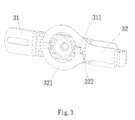
- FIG. 3is a view of the state in which the notch is aligned to the claw portion
- FIG. 4is a view of the state in which the lamp body is hooked by the hook
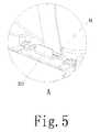
- FIG. 5is an enlarged view of part A in FIG. 4 ;
- FIG. 6is a view of the state in which the lamp has been mounted
- FIG. 6shows a state in which the lamp according to the embodiment has been mounted.
- the similarity between such state and the prior artis that the wires (not shown) connected between a lamp body 4 and a junction box 1 are shielded. This beautifies the lamp, but for a lamp in this state, the wires cannot be connected.
- the lamp body 4can be placed temporarily on a transition member 3 , so that the mounting personnel can connect the leads by both hands. The specific operations are as described below.
- a junction box assembly of the lamp according to the embodiment, as shown in FIG. 1includes a junction box 1 and a transition member 3 as shown in FIG. 2 ; the transition member 3 includes a mounting portion 31 and a placement portion 32 ; and the mounting portion 31 is provided with two claw portions 311 , one claw portion 311 and the body of the mounting portion 31 form one segment of the guide groove together, and the two claw portions 311 form two segments of the guide groove.
- the mounting process of the lampis as follows: the mounting portion 31 is coordinated with the mounting portion 31 as shown in FIG. 3 , such that a notch 322 on the inner side of a guide ring 321 is aligned to the claw portion 311 on the right; the guide ring 321 is inserted into the guide groove so that the mounting portion 31 is rotatably connected to the placement portion 32 ; then, the placement portion 32 is clockwise rotated to the position as shown in FIG. 2 , or rotated to other suitable position; the junction box 1 is mounted on a wall (not shown); the mounting portion 31 is mounted on the junction box 1 by screws 2 (as shown in FIG. 1 ); as shown in FIG. 4 and FIG.
- a cross beam 41(serving as a hooked portion) inside the lamp body 4 is aligned to a hook 323 at an end of the mounting portion 32 , so that the hook 323 can hook the lamp body 4 by the cross beam 41 , and in this state, the lamp is hung and the wires (not shown) connected between the lamp body and the mounting position are not shielded so that the mounting personnel can connect the leads between the lamp body 4 and the junction box 1 by both hands;
- the lamp body 4when the wires are connected, the lamp body 4 is rotated upward around the cross beam 41 to the junction box 1 (as shown in FIG. 6 ), and the mounting of the lamp body 4 and the junction box is completed by threaded connection.
- the wiresare shielded by the lamp body 4 and the junction box 1 , which beautifies the product.
Landscapes
- Engineering & Computer Science (AREA)
- General Engineering & Computer Science (AREA)
- Architecture (AREA)
- Power Engineering (AREA)
- Non-Portable Lighting Devices Or Systems Thereof (AREA)
- Fastening Of Light Sources Or Lamp Holders (AREA)
Abstract
Description
The present application relates to a lighting device and in particular to a lamp, and a transition member for mounting a lamp, a lamp body and a junction box assembly.
Some lamps include two parts: a lamp body and a junction box; wires are connected to the lamp body; and it is desired to connect the wires into the junction box. An induction lamp is mounted by, firstly, fixedly mounting the junction box, then connecting the wires into the junction box, and finally mounting the lamp body on the junction box. An induction lamp is usually mounted on a wall or roof in a high position. In the prior art, when mounting an induction lamp, it is desired to mount the induction lamp in a high position and there is no place to put the lamp body, such that the mounting personnel have to hold the lamp body with one hand, only the other hand could be free to connect the wires. Sometimes, even have to connect the wires with both hands while clamping the lamp body with their arms and body. It is quite inconvenient and inefficient to mount an induction lamp.
An objective of the present application is to make the connection of wires during the mounting of a lamp safe and convenient.
To achieve this, a lamp is provided, including: a lamp body and a transition member which is configured to mount the lamp body in a mounting position. The transition member includes a mounting portion and a placement portion which are connected together; the mounting portion is configured to be mounted in said mounting position; and the placement portion enables the lamp body to be placed thereon before the mounting is completed, and in this state, wires connected between the lamp body and the mounting position are not shielded so that it is possible to connect the wires.
Specifically, the placement portion is provided with a hook by which the lamp body is hooked before the mounting is completed; and the lamp body is provided with a hooked portion which is hooked by the hook.
Specifically, the lamp body can, when hooked, be rotated to the mounting position. Whereby, the lamp can be directly rotated to the mounting position after connecting the wires, so that it is efficient to conduct the following mounting.
Specifically, the lamp includes a junction box; and the lamp body is arranged on the junction box, that is, a corresponding position on the junction box is said mounting position.
The transition member for mounting a lamp provided by the present application is the transition member in the above-mentioned lamp.
The lamp body provided by the present application is the lamp body in the above-mentioned lamp.
The junction box assembly provided by the present application includes the junction box and the transition member in the above-mentioned lamp.
The mounting process of the lamp is as follows: the mounting portion is mounted in a mounting position, the lamp body is placed on the placement portion, and the wires connected between the lamp body and the mounting position are not shielded, so that the mounting personnel can connect the wires by both hands. The present application has the following beneficial effect: compared with the prior art, the transition member for mounting a lamp provided by the present application is more convenient for the mounting personnel to mount a lamp and improves the efficiency.
in which:
- 1: junction box;
- 2: screw;
- 3: transition member;
- 31: mounting portion;
- 311: claw portion;
- 32: placement portion;
- 321: guide ring;
- 322: notch;
- 323: hook;
- 4: lamp body; and
- 41: cross beam.
The present application will be further described in connection with the following embodiments.
A junction box assembly of the lamp according to the embodiment, as shown inFIG. 1 , includes ajunction box 1 and atransition member 3 as shown inFIG. 2 ; thetransition member 3 includes amounting portion 31 and aplacement portion 32; and themounting portion 31 is provided with twoclaw portions 311, oneclaw portion 311 and the body of themounting portion 31 form one segment of the guide groove together, and the twoclaw portions 311 form two segments of the guide groove.
The mounting process of the lamp is as follows: themounting portion 31 is coordinated with themounting portion 31 as shown inFIG. 3 , such that anotch 322 on the inner side of aguide ring 321 is aligned to theclaw portion 311 on the right; theguide ring 321 is inserted into the guide groove so that themounting portion 31 is rotatably connected to theplacement portion 32; then, theplacement portion 32 is clockwise rotated to the position as shown inFIG. 2 , or rotated to other suitable position; thejunction box 1 is mounted on a wall (not shown); themounting portion 31 is mounted on thejunction box 1 by screws2 (as shown inFIG. 1 ); as shown inFIG. 4 andFIG. 5 , a cross beam41 (serving as a hooked portion) inside thelamp body 4 is aligned to ahook 323 at an end of themounting portion 32, so that thehook 323 can hook thelamp body 4 by thecross beam 41, and in this state, the lamp is hung and the wires (not shown) connected between the lamp body and the mounting position are not shielded so that the mounting personnel can connect the leads between thelamp body 4 and thejunction box 1 by both hands; and
when the wires are connected, thelamp body 4 is rotated upward around thecross beam 41 to the junction box1 (as shown inFIG. 6 ), and the mounting of thelamp body 4 and the junction box is completed by threaded connection. When the lamp is well mounted, the wires are shielded by thelamp body 4 and thejunction box 1, which beautifies the product.
Finally, it should be noted that the embodiments above are merely provided for explaining the technical solution of the present application and not for limiting the protection scope of the present application. Although the present application has been described in detail by preferred embodiments, it should be understood by a person of ordinary skill in the art that the technical solution of the present application can be modified or equivalently replaced without departing from the essence and scope of the technical solution of the present application.
Claims (11)
1. A lamp, comprising a lamp body and a transition member which is configured to mount the lamp body in a mounting position, wherein,
the transition member comprises a mounting portion and a placement portion which are rotatably connected together; the mounting portion is configured to be mounted in said mounting position; and the placement portion enables the lamp body to be placed thereon before the mounting is completed, and in this state, the wires connected between the lamp body and the mounting position are not shielded so that it is possible to connect the wires.
2. The lamp according toclaim 1 , wherein, by the coordination of a guide ring and a segmented guide groove, the mounting portion and the placement portion are rotatably connected; and a notch is provided on the guide ring, by which the guide ring is inserted into the guide groove from one of the segmented guide groove.
3. The lamp according toclaim 2 , wherein said guide ring is arranged in the placement portion; and said guide groove is arranged in the mounting portion.
4. The lamp according toclaim 1 , wherein, the placement portion is provided with a hook by which the lamp body is hooked before the mounting is completed; and the lamp body is provided with a hooked portion which is hooked by the hook.
5. The lamp according toclaim 4 , wherein the hooked portion is a crossbeam.
6. The lamp according toclaim 5 , wherein, the lamp body can, when hooked, be rotated to said mounting position.
7. The lamp according toclaim 1 , wherein, when the mounting is completed, the wires connected between the lamp body and the mounting position are shielded so that it is impossible to connect the wires.
8. The lamp according to any one ofclaim 1 or2 to7 , comprising a junction box; and the lamp body is arranged on the junction box, that is, a corresponding position on the junction box is said mounting position.
9. A transition member for mounting a lamp, wherein, being the transition member in the lamp according to any one ofclaim 1 or2 to5 .
10. A lamp body, wherein, being the lamp body in the lamp according to any one ofclaims 5 to7 .
11. A junction box assembly, comprising the junction box and the transition member in the lamp according toclaim 8 .
Applications Claiming Priority (3)
| Application Number | Priority Date | Filing Date | Title |
|---|---|---|---|
| CN201610233628 | 2016-04-15 | ||
| CN201610233628.5 | 2016-04-15 | ||
| CN201610233628.5ACN105757618B (en) | 2016-04-15 | 2016-04-15 | Lamp, lamp mounting transition piece, lamp body and junction box assembly |
Publications (2)
| Publication Number | Publication Date |
|---|---|
| US20170299164A1 US20170299164A1 (en) | 2017-10-19 |
| US9863619B2true US9863619B2 (en) | 2018-01-09 |
Family
ID=56335043
Family Applications (1)
| Application Number | Title | Priority Date | Filing Date |
|---|---|---|---|
| US15/358,035Expired - Fee RelatedUS9863619B2 (en) | 2016-04-15 | 2016-11-21 | Lamp, transition member for mounting lamp, lamp body and junction box assembly |
Country Status (2)
| Country | Link |
|---|---|
| US (1) | US9863619B2 (en) |
| CN (1) | CN105757618B (en) |
Cited By (32)
| Publication number | Priority date | Publication date | Assignee | Title |
|---|---|---|---|---|
| USD832218S1 (en)* | 2017-09-18 | 2018-10-30 | Cooper Technologies Company | Junction box for regressed light engine |
| USD833977S1 (en)* | 2015-10-05 | 2018-11-20 | DMF, Inc. | Electrical junction box |
| US10408396B2 (en) | 2017-09-18 | 2019-09-10 | Cooper Technologies Company | Junction box for regressed light module |
| US10408395B2 (en) | 2013-07-05 | 2019-09-10 | DMF, Inc. | Recessed lighting systems |
| USD864877S1 (en) | 2019-01-29 | 2019-10-29 | DMF, Inc. | Plastic deep electrical junction box with a lighting module mounting yoke |
| US10488000B2 (en) | 2017-06-22 | 2019-11-26 | DMF, Inc. | Thin profile surface mount lighting apparatus |
| US10551044B2 (en) | 2015-11-16 | 2020-02-04 | DMF, Inc. | Recessed lighting assembly |
| US10563850B2 (en) | 2015-04-22 | 2020-02-18 | DMF, Inc. | Outer casing for a recessed lighting fixture |
| US10591120B2 (en) | 2015-05-29 | 2020-03-17 | DMF, Inc. | Lighting module for recessed lighting systems |
| US10663153B2 (en) | 2017-12-27 | 2020-05-26 | DMF, Inc. | Methods and apparatus for adjusting a luminaire |
| US10753558B2 (en) | 2013-07-05 | 2020-08-25 | DMF, Inc. | Lighting apparatus and methods |
| USD901398S1 (en) | 2019-01-29 | 2020-11-10 | DMF, Inc. | Plastic deep electrical junction box |
| USD902871S1 (en) | 2018-06-12 | 2020-11-24 | DMF, Inc. | Plastic deep electrical junction box |
| USD905327S1 (en) | 2018-05-17 | 2020-12-15 | DMF, Inc. | Light fixture |
| USD907284S1 (en) | 2014-02-18 | 2021-01-05 | DMF, Inc. | Module applied to a lighting assembly |
| US10975570B2 (en) | 2017-11-28 | 2021-04-13 | DMF, Inc. | Adjustable hanger bar assembly |
| US11060705B1 (en) | 2013-07-05 | 2021-07-13 | DMF, Inc. | Compact lighting apparatus with AC to DC converter and integrated electrical connector |
| US11067231B2 (en) | 2017-08-28 | 2021-07-20 | DMF, Inc. | Alternate junction box and arrangement for lighting apparatus |
| US11231154B2 (en) | 2018-10-02 | 2022-01-25 | Ver Lighting Llc | Bar hanger assembly with mating telescoping bars |
| US11255497B2 (en) | 2013-07-05 | 2022-02-22 | DMF, Inc. | Adjustable electrical apparatus with hangar bars for installation in a building |
| USD945054S1 (en) | 2017-06-22 | 2022-03-01 | DMF, Inc. | Light fixture |
| US11274821B2 (en) | 2019-09-12 | 2022-03-15 | DMF, Inc. | Lighting module with keyed heat sink coupled to thermally conductive trim |
| US11306903B2 (en) | 2020-07-17 | 2022-04-19 | DMF, Inc. | Polymer housing for a lighting system and methods for using same |
| US11391442B2 (en) | 2018-06-11 | 2022-07-19 | DMF, Inc. | Polymer housing for a recessed lighting system and methods for using same |
| US11435064B1 (en) | 2013-07-05 | 2022-09-06 | DMF, Inc. | Integrated lighting module |
| USD966877S1 (en) | 2019-03-14 | 2022-10-18 | Ver Lighting Llc | Hanger bar for a hanger bar assembly |
| USD970081S1 (en) | 2018-05-24 | 2022-11-15 | DMF, Inc. | Light fixture |
| US11585517B2 (en) | 2020-07-23 | 2023-02-21 | DMF, Inc. | Lighting module having field-replaceable optics, improved cooling, and tool-less mounting features |
| USD990030S1 (en) | 2020-07-17 | 2023-06-20 | DMF, Inc. | Housing for a lighting system |
| USD1012864S1 (en) | 2019-01-29 | 2024-01-30 | DMF, Inc. | Portion of a plastic deep electrical junction box |
| US12203631B2 (en) | 2020-07-16 | 2025-01-21 | DMF, Inc. | Round metal housing for a lighting system |
| US12297986B2 (en) | 2020-07-17 | 2025-05-13 | DMF, Inc. | Bar hanger assembly with crossmembers and housing assemblies using same |
Families Citing this family (4)
| Publication number | Priority date | Publication date | Assignee | Title |
|---|---|---|---|---|
| CA2970474A1 (en)* | 2016-06-22 | 2017-12-22 | MaxLite, Inc. | Security light assembly |
| USD999269S1 (en)* | 2020-09-07 | 2023-09-19 | Ningbo Fiercer Leopard Electrical Appliance Co., Ltd. | Induction lamp with camera |
| USD1003334S1 (en)* | 2020-09-07 | 2023-10-31 | Ningbo Fiercer Leopard Electrical Appliance Co., Ltd. | Induction lamp with camera |
| CN213576997U (en)* | 2020-09-30 | 2021-06-29 | 宁波赛豹电器有限公司 | Induction camera lamp easy and convenient to install |
Citations (7)
| Publication number | Priority date | Publication date | Assignee | Title |
|---|---|---|---|---|
| US2532528A (en)* | 1947-09-13 | 1950-12-05 | Leader Electric Mfg Corp | Mounting for overhead lighting fixtures |
| US2569859A (en)* | 1947-09-13 | 1951-10-02 | Andrew O Locke | Mounting assembly for fluorescent fixtures |
| US4162779A (en)* | 1977-12-14 | 1979-07-31 | The Miller Company | Outlet box mounting device |
| US6905222B1 (en)* | 2002-04-02 | 2005-06-14 | Genlyte Thomas Group Llc | Thermal isolation luminaire and wall mount system |
| US20070029456A1 (en)* | 2005-08-05 | 2007-02-08 | Genlyte Thomas Group, Llc | Track fixture with hinged accessory ring |
| US7658517B2 (en)* | 2005-07-22 | 2010-02-09 | Genlyte Thomas Group, Llc | Hinged doors for recessed light fixture |
| US20100091503A1 (en)* | 2008-10-14 | 2010-04-15 | Kuo Benny L | Lamp device |
Family Cites Families (5)
| Publication number | Priority date | Publication date | Assignee | Title |
|---|---|---|---|---|
| CN2733523Y (en)* | 2004-08-04 | 2005-10-12 | 河北理工大学 | Fixed connection device between electrical appliance and wall |
| WO2012031397A1 (en)* | 2010-09-09 | 2012-03-15 | 福建源光亚明电器有限公司 | Lamp structure for improved electrodeless lamp light source |
| CN202675165U (en)* | 2012-07-05 | 2013-01-16 | 宁波朗格照明电器有限公司 | Reflector suspending structure of lamp |
| US9086199B2 (en)* | 2013-08-29 | 2015-07-21 | Lite-On Technology Corporation | Lighting device installation method and lighting system |
| CN205592896U (en)* | 2016-04-15 | 2016-09-21 | 骏威企业有限公司 | Luminaires, Luminaire Installation Transitions, Luminaire Body and Junction Box Assemblies |
- 2016
- 2016-04-15CNCN201610233628.5Apatent/CN105757618B/ennot_activeExpired - Fee Related
- 2016-11-21USUS15/358,035patent/US9863619B2/ennot_activeExpired - Fee Related
Patent Citations (7)
| Publication number | Priority date | Publication date | Assignee | Title |
|---|---|---|---|---|
| US2532528A (en)* | 1947-09-13 | 1950-12-05 | Leader Electric Mfg Corp | Mounting for overhead lighting fixtures |
| US2569859A (en)* | 1947-09-13 | 1951-10-02 | Andrew O Locke | Mounting assembly for fluorescent fixtures |
| US4162779A (en)* | 1977-12-14 | 1979-07-31 | The Miller Company | Outlet box mounting device |
| US6905222B1 (en)* | 2002-04-02 | 2005-06-14 | Genlyte Thomas Group Llc | Thermal isolation luminaire and wall mount system |
| US7658517B2 (en)* | 2005-07-22 | 2010-02-09 | Genlyte Thomas Group, Llc | Hinged doors for recessed light fixture |
| US20070029456A1 (en)* | 2005-08-05 | 2007-02-08 | Genlyte Thomas Group, Llc | Track fixture with hinged accessory ring |
| US20100091503A1 (en)* | 2008-10-14 | 2010-04-15 | Kuo Benny L | Lamp device |
Cited By (59)
| Publication number | Priority date | Publication date | Assignee | Title |
|---|---|---|---|---|
| US11085597B2 (en) | 2013-07-05 | 2021-08-10 | DMF, Inc. | Recessed lighting systems |
| US10753558B2 (en) | 2013-07-05 | 2020-08-25 | DMF, Inc. | Lighting apparatus and methods |
| US10982829B2 (en) | 2013-07-05 | 2021-04-20 | DMF, Inc. | Adjustable electrical apparatus with hangar bars for installation in a building |
| US11255497B2 (en) | 2013-07-05 | 2022-02-22 | DMF, Inc. | Adjustable electrical apparatus with hangar bars for installation in a building |
| US11435064B1 (en) | 2013-07-05 | 2022-09-06 | DMF, Inc. | Integrated lighting module |
| US10408395B2 (en) | 2013-07-05 | 2019-09-10 | DMF, Inc. | Recessed lighting systems |
| US12352405B2 (en) | 2013-07-05 | 2025-07-08 | DMF, Inc. | Adjustable electrical apparatus with hangar bars for installation in a building |
| US11808430B2 (en) | 2013-07-05 | 2023-11-07 | DMF, Inc. | Adjustable electrical apparatus with hangar bars for installation in a building |
| US12000562B2 (en) | 2013-07-05 | 2024-06-04 | DMF, Inc. | Lighting assembly with AC to DC converter and heat-sinking housing |
| US10816148B2 (en) | 2013-07-05 | 2020-10-27 | DMF, Inc. | Recessed lighting systems |
| US11060705B1 (en) | 2013-07-05 | 2021-07-13 | DMF, Inc. | Compact lighting apparatus with AC to DC converter and integrated electrical connector |
| USD924467S1 (en) | 2014-02-18 | 2021-07-06 | DMF, Inc. | Unified casting light module |
| US11028982B2 (en) | 2014-02-18 | 2021-06-08 | DMF, Inc. | Adjustable lighting assembly with hangar bars |
| USD907284S1 (en) | 2014-02-18 | 2021-01-05 | DMF, Inc. | Module applied to a lighting assembly |
| USD939134S1 (en) | 2014-02-18 | 2021-12-21 | DMF, Inc. | Module applied to a lighting assembly |
| US10563850B2 (en) | 2015-04-22 | 2020-02-18 | DMF, Inc. | Outer casing for a recessed lighting fixture |
| US11118768B2 (en) | 2015-04-22 | 2021-09-14 | DMF, Inc. | Outer casing for a recessed lighting fixture |
| US11435066B2 (en) | 2015-04-22 | 2022-09-06 | DMF, Inc. | Outer casing for a recessed lighting fixture |
| US10591120B2 (en) | 2015-05-29 | 2020-03-17 | DMF, Inc. | Lighting module for recessed lighting systems |
| USD925109S1 (en) | 2015-05-29 | 2021-07-13 | DMF, Inc. | Lighting module |
| US11022259B2 (en) | 2015-05-29 | 2021-06-01 | DMF, Inc. | Lighting module with separated light source and power supply circuit board |
| USD848375S1 (en) | 2015-10-05 | 2019-05-14 | DMF, Inc. | Electrical junction box |
| USD851046S1 (en)* | 2015-10-05 | 2019-06-11 | DMF, Inc. | Electrical Junction Box |
| USD944212S1 (en) | 2015-10-05 | 2022-02-22 | DMF, Inc. | Electrical junction box |
| USD833977S1 (en)* | 2015-10-05 | 2018-11-20 | DMF, Inc. | Electrical junction box |
| US10551044B2 (en) | 2015-11-16 | 2020-02-04 | DMF, Inc. | Recessed lighting assembly |
| US11242983B2 (en) | 2015-11-16 | 2022-02-08 | DMF, Inc. | Casing for lighting assembly |
| US11668455B2 (en) | 2015-11-16 | 2023-06-06 | DMF, Inc. | Casing for lighting assembly |
| US11649938B2 (en) | 2017-06-22 | 2023-05-16 | DMF, Inc. | Thin profile surface mount lighting apparatus |
| US10488000B2 (en) | 2017-06-22 | 2019-11-26 | DMF, Inc. | Thin profile surface mount lighting apparatus |
| US11047538B2 (en) | 2017-06-22 | 2021-06-29 | DMF, Inc. | LED lighting apparatus with adapter bracket for a junction box |
| US10663127B2 (en) | 2017-06-22 | 2020-05-26 | DMF, Inc. | Thin profile surface mount lighting apparatus |
| USD945054S1 (en) | 2017-06-22 | 2022-03-01 | DMF, Inc. | Light fixture |
| US11293609B2 (en) | 2017-06-22 | 2022-04-05 | DMF, Inc. | Thin profile surface mount lighting apparatus |
| US12169053B2 (en) | 2017-08-28 | 2024-12-17 | DMF, Inc. | Alternate junction box and arrangement for lighting apparatus |
| US11067231B2 (en) | 2017-08-28 | 2021-07-20 | DMF, Inc. | Alternate junction box and arrangement for lighting apparatus |
| US10408396B2 (en) | 2017-09-18 | 2019-09-10 | Cooper Technologies Company | Junction box for regressed light module |
| USD832218S1 (en)* | 2017-09-18 | 2018-10-30 | Cooper Technologies Company | Junction box for regressed light engine |
| US10975570B2 (en) | 2017-11-28 | 2021-04-13 | DMF, Inc. | Adjustable hanger bar assembly |
| US11448384B2 (en) | 2017-12-27 | 2022-09-20 | DMF, Inc. | Methods and apparatus for adjusting a luminaire |
| US10663153B2 (en) | 2017-12-27 | 2020-05-26 | DMF, Inc. | Methods and apparatus for adjusting a luminaire |
| USD905327S1 (en) | 2018-05-17 | 2020-12-15 | DMF, Inc. | Light fixture |
| USD970081S1 (en) | 2018-05-24 | 2022-11-15 | DMF, Inc. | Light fixture |
| US11391442B2 (en) | 2018-06-11 | 2022-07-19 | DMF, Inc. | Polymer housing for a recessed lighting system and methods for using same |
| USD902871S1 (en) | 2018-06-12 | 2020-11-24 | DMF, Inc. | Plastic deep electrical junction box |
| USD903605S1 (en) | 2018-06-12 | 2020-12-01 | DMF, Inc. | Plastic deep electrical junction box |
| US11231154B2 (en) | 2018-10-02 | 2022-01-25 | Ver Lighting Llc | Bar hanger assembly with mating telescoping bars |
| USD901398S1 (en) | 2019-01-29 | 2020-11-10 | DMF, Inc. | Plastic deep electrical junction box |
| USD1012864S1 (en) | 2019-01-29 | 2024-01-30 | DMF, Inc. | Portion of a plastic deep electrical junction box |
| USD864877S1 (en) | 2019-01-29 | 2019-10-29 | DMF, Inc. | Plastic deep electrical junction box with a lighting module mounting yoke |
| USD966877S1 (en) | 2019-03-14 | 2022-10-18 | Ver Lighting Llc | Hanger bar for a hanger bar assembly |
| US11274821B2 (en) | 2019-09-12 | 2022-03-15 | DMF, Inc. | Lighting module with keyed heat sink coupled to thermally conductive trim |
| US12203631B2 (en) | 2020-07-16 | 2025-01-21 | DMF, Inc. | Round metal housing for a lighting system |
| USD990030S1 (en) | 2020-07-17 | 2023-06-20 | DMF, Inc. | Housing for a lighting system |
| US11306903B2 (en) | 2020-07-17 | 2022-04-19 | DMF, Inc. | Polymer housing for a lighting system and methods for using same |
| US12209736B2 (en) | 2020-07-17 | 2025-01-28 | DMF, Inc. | Polymer housing for a lighting system and methods for using same |
| US12297986B2 (en) | 2020-07-17 | 2025-05-13 | DMF, Inc. | Bar hanger assembly with crossmembers and housing assemblies using same |
| US11585517B2 (en) | 2020-07-23 | 2023-02-21 | DMF, Inc. | Lighting module having field-replaceable optics, improved cooling, and tool-less mounting features |
| US12372222B2 (en) | 2020-07-23 | 2025-07-29 | DMF, Inc. | Lighting module having field-replaceable optics, improved cooling, and tool-less mounting features |
Also Published As
| Publication number | Publication date |
|---|---|
| CN105757618A (en) | 2016-07-13 |
| US20170299164A1 (en) | 2017-10-19 |
| CN105757618B (en) | 2019-07-16 |
Similar Documents
| Publication | Publication Date | Title |
|---|---|---|
| US9863619B2 (en) | Lamp, transition member for mounting lamp, lamp body and junction box assembly | |
| CN203491397U (en) | Split type alarm grounding device | |
| CN205123131U (en) | Insulating guard shield mounting tool | |
| CN203733963U (en) | ground wire | |
| CN205102076U (en) | Quick connect buckle | |
| CN205605992U (en) | Tap mounting base | |
| CN104696595A (en) | Temporary fixing device for wire | |
| CN202392391U (en) | Simple structure for surface mounting of dome camera | |
| CN203225443U (en) | Wire clamping pincers provided with a screwdriver | |
| CN106763019A (en) | A kind of attachment means for being applied to fast assembling-disassembling cable drag chain | |
| CN205592896U (en) | Luminaires, Luminaire Installation Transitions, Luminaire Body and Junction Box Assemblies | |
| CN207681895U (en) | A kind of vacuum screw location structure | |
| CN203367715U (en) | Grounding wire operating rod | |
| CN206195066U (en) | Plug -in quick -operation joint | |
| CN205135122U (en) | Handle of supplementary installation swivel nut in area | |
| CN207122878U (en) | Glass hood mounting structure | |
| CN208381820U (en) | Beer infuses lamp | |
| CN204597093U (en) | General three prongs of plug aid | |
| CN205465803U (en) | Convenient type power cable calliper | |
| CN204205171U (en) | A kind of novel grounded line structure | |
| CN205290764U (en) | Insulating spanner of electric power | |
| CN204091415U (en) | A kind of handle | |
| CN105650079A (en) | Mechanical connector | |
| CN218334694U (en) | Communication cable surface peeling machine | |
| CN103050797B (en) | Power splicing tube |
Legal Events
| Date | Code | Title | Description |
|---|---|---|---|
| AS | Assignment | Owner name:SMART HERO ENTERPRISES LIMITED, CHINA Free format text:ASSIGNMENT OF ASSIGNORS INTEREST;ASSIGNOR:MAK, WILSON YU SANG;REEL/FRAME:040395/0794 Effective date:20161118 | |
| STCF | Information on status: patent grant | Free format text:PATENTED CASE | |
| FEPP | Fee payment procedure | Free format text:MAINTENANCE FEE REMINDER MAILED (ORIGINAL EVENT CODE: REM.); ENTITY STATUS OF PATENT OWNER: SMALL ENTITY | |
| LAPS | Lapse for failure to pay maintenance fees | Free format text:PATENT EXPIRED FOR FAILURE TO PAY MAINTENANCE FEES (ORIGINAL EVENT CODE: EXP.); ENTITY STATUS OF PATENT OWNER: SMALL ENTITY | |
| STCH | Information on status: patent discontinuation | Free format text:PATENT EXPIRED DUE TO NONPAYMENT OF MAINTENANCE FEES UNDER 37 CFR 1.362 | |
| FP | Lapsed due to failure to pay maintenance fee | Effective date:20220109 |