US9861937B2 - Advancements in osmotically driven membrane systems including low pressure control - Google Patents
Advancements in osmotically driven membrane systems including low pressure controlDownload PDFInfo
- Publication number
- US9861937B2 US9861937B2US14/777,406US201414777406AUS9861937B2US 9861937 B2US9861937 B2US 9861937B2US 201414777406 AUS201414777406 AUS 201414777406AUS 9861937 B2US9861937 B2US 9861937B2
- Authority
- US
- United States
- Prior art keywords
- stream
- pressure
- draw
- flow rate
- pump
- Prior art date
- Legal status (The legal status is an assumption and is not a legal conclusion. Google has not performed a legal analysis and makes no representation as to the accuracy of the status listed.)
- Active
Links
Images


Classifications
- B—PERFORMING OPERATIONS; TRANSPORTING
- B01—PHYSICAL OR CHEMICAL PROCESSES OR APPARATUS IN GENERAL
- B01D—SEPARATION
- B01D61/00—Processes of separation using semi-permeable membranes, e.g. dialysis, osmosis or ultrafiltration; Apparatus, accessories or auxiliary operations specially adapted therefor
- B01D61/58—Multistep processes
- B—PERFORMING OPERATIONS; TRANSPORTING
- B01—PHYSICAL OR CHEMICAL PROCESSES OR APPARATUS IN GENERAL
- B01D—SEPARATION
- B01D61/00—Processes of separation using semi-permeable membranes, e.g. dialysis, osmosis or ultrafiltration; Apparatus, accessories or auxiliary operations specially adapted therefor
- B01D61/002—Forward osmosis or direct osmosis
- B01D61/0022—Apparatus therefor
- B—PERFORMING OPERATIONS; TRANSPORTING
- B01—PHYSICAL OR CHEMICAL PROCESSES OR APPARATUS IN GENERAL
- B01D—SEPARATION
- B01D61/00—Processes of separation using semi-permeable membranes, e.g. dialysis, osmosis or ultrafiltration; Apparatus, accessories or auxiliary operations specially adapted therefor
- B01D61/02—Reverse osmosis; Hyperfiltration ; Nanofiltration
- B01D61/022—
- B—PERFORMING OPERATIONS; TRANSPORTING
- B01—PHYSICAL OR CHEMICAL PROCESSES OR APPARATUS IN GENERAL
- B01D—SEPARATION
- B01D61/00—Processes of separation using semi-permeable membranes, e.g. dialysis, osmosis or ultrafiltration; Apparatus, accessories or auxiliary operations specially adapted therefor
- B01D61/02—Reverse osmosis; Hyperfiltration ; Nanofiltration
- B01D61/025—Reverse osmosis; Hyperfiltration
- B—PERFORMING OPERATIONS; TRANSPORTING
- B01—PHYSICAL OR CHEMICAL PROCESSES OR APPARATUS IN GENERAL
- B01D—SEPARATION
- B01D61/00—Processes of separation using semi-permeable membranes, e.g. dialysis, osmosis or ultrafiltration; Apparatus, accessories or auxiliary operations specially adapted therefor
- B01D61/02—Reverse osmosis; Hyperfiltration ; Nanofiltration
- B01D61/027—Nanofiltration
- B—PERFORMING OPERATIONS; TRANSPORTING
- B01—PHYSICAL OR CHEMICAL PROCESSES OR APPARATUS IN GENERAL
- B01D—SEPARATION
- B01D61/00—Processes of separation using semi-permeable membranes, e.g. dialysis, osmosis or ultrafiltration; Apparatus, accessories or auxiliary operations specially adapted therefor
- B01D61/02—Reverse osmosis; Hyperfiltration ; Nanofiltration
- B01D61/029—Multistep processes comprising different kinds of membrane processes selected from reverse osmosis, hyperfiltration or nanofiltration
- B—PERFORMING OPERATIONS; TRANSPORTING
- B01—PHYSICAL OR CHEMICAL PROCESSES OR APPARATUS IN GENERAL
- B01D—SEPARATION
- B01D61/00—Processes of separation using semi-permeable membranes, e.g. dialysis, osmosis or ultrafiltration; Apparatus, accessories or auxiliary operations specially adapted therefor
- B01D61/02—Reverse osmosis; Hyperfiltration ; Nanofiltration
- B01D61/06—Energy recovery
- B—PERFORMING OPERATIONS; TRANSPORTING
- B01—PHYSICAL OR CHEMICAL PROCESSES OR APPARATUS IN GENERAL
- B01D—SEPARATION
- B01D61/00—Processes of separation using semi-permeable membranes, e.g. dialysis, osmosis or ultrafiltration; Apparatus, accessories or auxiliary operations specially adapted therefor
- B01D61/02—Reverse osmosis; Hyperfiltration ; Nanofiltration
- B01D61/12—Controlling or regulating
- B—PERFORMING OPERATIONS; TRANSPORTING
- B01—PHYSICAL OR CHEMICAL PROCESSES OR APPARATUS IN GENERAL
- B01D—SEPARATION
- B01D65/00—Accessories or auxiliary operations, in general, for separation processes or apparatus using semi-permeable membranes
- B01D65/02—Membrane cleaning or sterilisation ; Membrane regeneration
- C—CHEMISTRY; METALLURGY
- C02—TREATMENT OF WATER, WASTE WATER, SEWAGE, OR SLUDGE
- C02F—TREATMENT OF WATER, WASTE WATER, SEWAGE, OR SLUDGE
- C02F1/00—Treatment of water, waste water, or sewage
- C02F1/44—Treatment of water, waste water, or sewage by dialysis, osmosis or reverse osmosis
- C02F1/441—Treatment of water, waste water, or sewage by dialysis, osmosis or reverse osmosis by reverse osmosis
- C—CHEMISTRY; METALLURGY
- C02—TREATMENT OF WATER, WASTE WATER, SEWAGE, OR SLUDGE
- C02F—TREATMENT OF WATER, WASTE WATER, SEWAGE, OR SLUDGE
- C02F1/00—Treatment of water, waste water, or sewage
- C02F1/44—Treatment of water, waste water, or sewage by dialysis, osmosis or reverse osmosis
- C02F1/445—Treatment of water, waste water, or sewage by dialysis, osmosis or reverse osmosis by forward osmosis
- B—PERFORMING OPERATIONS; TRANSPORTING
- B01—PHYSICAL OR CHEMICAL PROCESSES OR APPARATUS IN GENERAL
- B01D—SEPARATION
- B01D2311/00—Details relating to membrane separation process operations and control
- B01D2311/14—Pressure control
- B—PERFORMING OPERATIONS; TRANSPORTING
- B01—PHYSICAL OR CHEMICAL PROCESSES OR APPARATUS IN GENERAL
- B01D—SEPARATION
- B01D2311/00—Details relating to membrane separation process operations and control
- B01D2311/25—Recirculation, recycling or bypass, e.g. recirculation of concentrate into the feed
- B01D2311/252—Recirculation of concentrate
- B01D2311/2521—Recirculation of concentrate to permeate side
- B—PERFORMING OPERATIONS; TRANSPORTING
- B01—PHYSICAL OR CHEMICAL PROCESSES OR APPARATUS IN GENERAL
- B01D—SEPARATION
- B01D2311/00—Details relating to membrane separation process operations and control
- B01D2311/25—Recirculation, recycling or bypass, e.g. recirculation of concentrate into the feed
- B01D2311/252—Recirculation of concentrate
- B01D2311/2523—Recirculation of concentrate to feed side
- B—PERFORMING OPERATIONS; TRANSPORTING
- B01—PHYSICAL OR CHEMICAL PROCESSES OR APPARATUS IN GENERAL
- B01D—SEPARATION
- B01D2313/00—Details relating to membrane modules or apparatus
- B01D2313/24—Specific pressurizing or depressurizing means
- B01D2313/243—Pumps
- B—PERFORMING OPERATIONS; TRANSPORTING
- B01—PHYSICAL OR CHEMICAL PROCESSES OR APPARATUS IN GENERAL
- B01D—SEPARATION
- B01D2313/00—Details relating to membrane modules or apparatus
- B01D2313/24—Specific pressurizing or depressurizing means
- B01D2313/246—Energy recovery means
- B—PERFORMING OPERATIONS; TRANSPORTING
- B01—PHYSICAL OR CHEMICAL PROCESSES OR APPARATUS IN GENERAL
- B01D—SEPARATION
- B01D2317/00—Membrane module arrangements within a plant or an apparatus
- B01D2317/02—Elements in series
- B—PERFORMING OPERATIONS; TRANSPORTING
- B01—PHYSICAL OR CHEMICAL PROCESSES OR APPARATUS IN GENERAL
- B01D—SEPARATION
- B01D2317/00—Membrane module arrangements within a plant or an apparatus
- B01D2317/02—Elements in series
- B01D2317/025—Permeate series
- B—PERFORMING OPERATIONS; TRANSPORTING
- B01—PHYSICAL OR CHEMICAL PROCESSES OR APPARATUS IN GENERAL
- B01D—SEPARATION
- B01D2317/00—Membrane module arrangements within a plant or an apparatus
- B01D2317/08—Use of membrane modules of different kinds
- B—PERFORMING OPERATIONS; TRANSPORTING
- B01—PHYSICAL OR CHEMICAL PROCESSES OR APPARATUS IN GENERAL
- B01D—SEPARATION
- B01D2321/00—Details relating to membrane cleaning, regeneration, sterilization or to the prevention of fouling
- B01D2321/16—Use of chemical agents
- B—PERFORMING OPERATIONS; TRANSPORTING
- B01—PHYSICAL OR CHEMICAL PROCESSES OR APPARATUS IN GENERAL
- B01D—SEPARATION
- B01D2321/00—Details relating to membrane cleaning, regeneration, sterilization or to the prevention of fouling
- B01D2321/16—Use of chemical agents
- B01D2321/167—Use of scale inhibitors
- B—PERFORMING OPERATIONS; TRANSPORTING
- B01—PHYSICAL OR CHEMICAL PROCESSES OR APPARATUS IN GENERAL
- B01D—SEPARATION
- B01D2325/00—Details relating to properties of membranes
- B01D2325/20—Specific permeability or cut-off range
Definitions
- Examples described hereinrelate to separation systems, elements, and methods which may be used for forward osmosis (FO) or reverse osmosis (RO), or generally any separation process.
- FOforward osmosis
- ROreverse osmosis
- Osmotically driven membrane processesare capable of treating high fouling solutions in an energy efficient manner by using a chemical energy gradient between two solutions to drive water flux across a membrane.
- Osmotic pre-treatment processesutilize a draw solution with a high osmotic potential, or osmotic pressure, relative to the feed solution to provide a driving force for water transport across a membrane. As relatively pure water flows across the membrane, it dilutes the draw solution.
- Typical systemsemploy either desalination equipment such as reverse osmosis, distillation, or other salt separation technique, or other methods for draw solute recovery such as thermally switching salts.
- desalination equipmentsuch as reverse osmosis, distillation, or other salt separation technique, or other methods for draw solute recovery such as thermally switching salts.
- these systemsare controlled as two separate sub-systems, an osmotic system and a re-concentration system, with a buffer volume between them and two separate pumping systems. The separate pumping systems regulate the flowrate and pressure of each stream.
- the overall rate of production in an osmotic systemis dictated by the flow of water across the osmotic membrane, which is determined in large part by the differential of the draw solution osmotic pressure to the feed solution osmotic pressure.
- the draw solution concentrationis controlled by adding solute to the draw solution with an injection pump and a draw solution buffer tank.
- draw solution osmotic potentialmust be higher than the feed to be treated.
- high feed water concentrationsmay necessitate draw solution concentrations that are higher than typically treatable to reconcentrate in lower energy desalination technologies, such as reverse osmosis (RO).
- ROreverse osmosis
- the energy recovery pumps generally used in conventional RO systemscan also be operated in a different way in order to be utilized for pressure retarded osmosis (PRO) systems.
- PROpressure retarded osmosis
- a high osmotic potential draw solutionis diluted by a low osmotic potential feed solution.
- the osmotic driving forceis partially offset by pressurizing the draw solution, but water flux is still in the direction of the draw solution.
- the excess water in the draw solutionis relieved through an energy generating device such as a turbine.
- an apparatusmay include a forward osmosis module configured to receive a feed stream, a draw stream, and produce a reject feed stream and an intermediate stream; a pressure sensor which may measure a first pressure on a draw side of the forward osmosis module; and a membrane module which may receive the intermediate stream and produce a product stream.
- the apparatusmay further include a hydraulic pump which may circulate the intermediate stream and pressurize it to a second pressure.
- the apparatusmay further include an energy recovery device which may lower the draw stream from the second pressure to the first pressure; a dosing pump which may provide a concentrated draw solution to the draw stream; and a flow meter which may measure the flow rate of the produce stream.
- An example methodmay include providing a feed stream to a forward osmosis module; providing a draw stream to the forward osmosis module; concentrating the feed stream and circulating the draw stream through the forward osmosis module which may produce an intermediate stream; monitoring a pressure on a draw side of the forward osmosis module; pumping the intermediate stream to another filter module; filtering the intermediate stream with another filter module which may produce the draw stream and a product stream.
- the methodmay further include monitoring a flow rate of the product stream and providing solute to the draw stream at a dosing rate that may be based, at least in part, on the flow rate of the product stream.
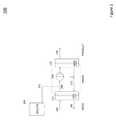
- FIG. 1is a purification system according to an embodiment of the invention.
- FIG. 2is a purification system according to another embodiment of the invention.
- FIG. 3is an energy recovery device according to an embodiment of the invention.
- a purification system 100 according to an embodiment of the inventionis illustrated as a block diagram in FIG. 1 .
- a system in steady stateis considered.
- the purification systemincludes an array of forward osmosis (FO) membrane elements in a FO module 4 , which may include one or more FO membrane elements plumbed in series, parallel or some combination of both.
- the FO module 4may have four ports—one port for receipt of a feed stream 3 , one port for receipt of a draw stream 17 , one port for producing a reject feed stream 5 , and one port for producing an intermediate stream 6 .
- the purification system 100further includes another membrane module 13 , which may be a reverse osmosis (RO) module.
- the membrane module 13may include one or more RO membrane elements plumbed in series, parallel or some combination of both.
- the membrane module 13may include three ports—one port for receipt of a pressurized intermediate stream 12 , one port for producing a product stream 15 , and one port for producing a draw stream 16 .
- a feed stream 1may be pressurized by a feed pump 2 forming a low pressure feed stream 3 .
- any feed streammay be used for which purification is desired, including but not limited to, seawater or wastewater.
- Stream 3may be plumbed into an FO module 4 , where the flow rate of the stream may be reduced as pure water transfers across the FO membrane at some FO permeate flow rate to the draw stream 17 .
- the feed solutemay be retained in the feed stream and rejected from the system in a reject feed stream 5 , e.g. a waste stream at a flow rate of stream 3 minus the FO permeate flow rate.
- a draw stream 17may have some osmotic pressure higher than that of the feed solution stream 3 and a hydrostatic pressure near atmospheric and may be plumbed into the array of FO module 4 , where the stream may be increased as pure water transfers across the FO membrane from the feed stream 3 at some FO permeate flow rate.
- the draw streamexits the element forming an intermediate stream 6 (e.g. an intermediate product stream), where it may be pressurized by a pump 9 (e.g. a hydraulic pump powered by an electric motor 8 ), to a hydrostatic pressure greater than the osmotic pressure of the draw in stream 17 , forming a pressurized intermediate product stream 12 .
- a pump 9e.g. a hydraulic pump powered by an electric motor 8
- Stream 12may then be plumbed into an array of membrane elements in membrane module 13 , which may in some examples be an RO module, where the flow rate of the stream may be reduced as pure water transfers across the RO membrane at some RO permeate flow rate.
- This RO permeateforms product stream 15 at some RO permeate flow rate, which is the product water of the system.
- the RO module 13may also produce a concentrated draw that exits the RO module 13 , forming pressurized draw stream 16 , having a flow rate equal to stream 17 .
- Stream 16is depressurized across a hydraulic motor 10 , also referred to as an energy recovery device, forming draw stream 17 , which may be at some pressure near atmospheric, recycling the draw solution. In some examples, multiple energy recovery devices may be used.
- draw solutemay be slowly lost across the FO module 4 and membrane module 13 into the waste stream 5 and product stream 15 , respectively.
- a dosing solutioncomprising a concentrated draw solution 18
- the solute of the draw solutionmay be sodium chloride, but other solutes may be used.
- the mean FO permeate flow rate and RO permeate flow ratemay be equal to one another for the system to remain in steady state within minutes.
- a draw solution buffer tank(not pictured) is added to intermediate product stream 6 , allowing for a variable draw solution volume.
- This draw solution buffer tankallows the FO permeate flow rate and RO permeate flow rate to fluctuate with respect to one another over time, providing for a simple control scheme. Dosing solution may be added without modifying either permeate flow rate.
- the draw solution buffer tank of convention systemsallows for simpler control of the purification system, but has several disadvantages.
- disadvantages of conventional systems and advantages of examples described hereinare provided by way of example to facilitate understanding. It is to be understood that not all examples may have all, or even any, of the described advantages, and not all examples may solve all, or even any, of the described conventional system disadvantages.
- One disadvantage of a conventional buffer tank systemmay be that the buffer tank significantly increases the weight and volume of the purification system.
- a typical system as illustrated in FIG. 1may have a volume of approximately twenty gallons, and a buffer tank may have a volume of approximately one hundred gallons. Due in part to the large volume, the response time of the conventional system is slow to adapt to changes in feed conditions or required permeate rates.
- buffer tankalso increases the risk of bio growth.
- the slow or lack of flow in the buffer tankincreases the likelihood of bacteria or other biological material to grow. This bio growth may contaminate the rest of the system, and additional filters or purification elements may be required to remove the bio growth.
- Examples described hereininclude use of a pressure control system which may allow for a purification system without a need for, or a reduced need for, a buffer tank.
- a pressure control systemwhich may allow for a purification system without a need for, or a reduced need for, a buffer tank.
- the draw solution volumemay become a fixed constant, or closer to a fixed constant, negating small changes in volume of the FO module 4 , RO module 13 , pumps and plumbing components.
- the resulting FO permeate flow rate and RO permeate flow ratemay become hydraulically locked (e.g. equal or in some other fixed relationship) to one another.
- Examples of pressure-controlled systemsmay have the following advantages over conventional state of the art FO/RO systems: A reduced size and weight may result from removing the draw solution buffer tank and reducing the draw volume. Decreased system response time may result from reducing the draw solution volume, allowing the draw solution concentration to be changed more rapidly to adapt to changes in feed conditions or required permeate rates. Decreased risk of bio growth may result from keeping the entire draw solution volume within relatively high velocity plumbing. Precise control of FO draw solution pressure may be possible as a result of removing the exposure of the draw solution to atmospheric pressure. It may also allow the pressure differential between the feed and draw pressure to be precisely controlled resulting in higher flux and lower propensity to fouling. Increased hydraulic efficiency may result from draw solution pressure being conserved as the draw solution is never exposed to atmosphere. These possible advantages may also result in reduced costs of producing and operating the system.
- examples of water purification systems using pressure controlinclude a pump between the FO module and the later membrane module (e.g. RO module) which pressurizes the intermediate stream provided from the FO module to a pressurized intermediate stream provided to the membrane module.
- the amount of pressurizatione.g. the flow rate of the pump
- a pressure sensormay be provided to measure pressure of the intermediate stream provided at an output of the FO module, or pressure of the draw stream provided to the FO module, or pressure on a draw side between elements of the FO module, or combinations thereof.
- a pressure of an input stream to the later membrane module(e.g. RO module) may be varied, which may vary the permeate flow rate through that later membrane module.
- a flow rate of the product stream provided by the membrane modulemay be maintained proportional to (e.g. equal to in some examples) a pressure on the draw side of the forward osmosis module. Accordingly, the permeate flow rates through the FO module and the later membrane module may be kept equal in some examples.
- a pressure control systemis considered with a single fixed displacement high pressure hydraulic pump 9 driven by electric motor 8 , and including an integrated fixed displacement hydraulic motor 10 such that the RO product flow rate is a direct function of electric motor 8 speed.
- An example of this pumpis Spectra Watermakers, Inc. SP5 Pearson Pump and the Danfoss SWPE.
- a high pressure pump with a separate energy devicemay also be applicable along with an array of any of these devices.
- other pumpsmay be used, including pumps whose flow rates are set using other mechanisms than electric motors.
- the systemmay include a pressure sensor or transducer 7 may be positioned to measure pressure of stream 6 or alternately or in addition, may be located on stream 17 (not shown), or alternatively or in addition at a location between elements on a draw side of the FO module 4 .
- a flow meter 14may additionally in some examples be positioned to measure a flow rate on the RO product steam 15 .
- the flow meter 14may be replaced with logic that calculates flow in some other way in other examples.
- both the FO permeate flow rate and RO permeate flow ratemay be hydraulically locked to a particular value.
- the hydraulic pressure of the draw solutions in stream 6 , 12 , 16 and 17may be determined by the particular permeate flow rates and the osmotic driving forces across the respective modules 4 and 13 .
- the RO pressures in streams 12 and 16may go to whatever pressure is required to overcome the osmotic pressure of the draw solution and produce the explicit RO permeate flow rate.
- the FO pressures in streams 17 and 6may go to whatever pressures are required to retard or assist the osmotic pressure differential across the FO membrane array 4 to produce the particular FO permeate flow rate.
- the FO permeate flow ratemay require assistance, for example, by increasing feed hydraulic pressure higher than draw hydraulic pressure; or retardation, for example, by increasing draw hydraulic pressure higher than feed hydraulic pressure, due to changes in the feed and draw osmotic pressure, flow rate, temperature, pH, and/or change in membrane performance properties.
- the system control schememay control the electric motor 8 speed with feedback from the pressure transducer 7 .
- the systemmay include a pump controller 20 (e.g. microcontroller, processor, circuitry, or combinations thereof) that may use a proportional integral derivative (PID) control algorithm or other method to set a flow rate of the pump 9 dynamically to maintain a desired pressure at the pressure transducer 7 .
- PIDproportional integral derivative
- This pressuremay be pre-determined, or calculated in real time to achieve a given pressure differential between the feed and draw hydraulic pressures.
- the pressurebegins to exceed the desired pressure, it may be an indicator that the system should retard the FO permeate flow rate and the control algorithm may increase the speed of the electric motor 8 , thus increasing the FO permeate flow rate (the flow rate water across the membrane or stream 6 less stream 17 ) and RO permeate flow rate 15 . This may alleviate the pressure at the pressure transducer 7 , thus removing the retardation of the FO permeate flow rate. If the pressure of the pressure transducer 7 begins to drop below the desired pressure, it may be an indicator that the system should assist the FO permeate flow rate, and the control algorithm may decrease the speed of the electric motor 8 , thus decreasing the FO permeate flow rate and RO permeate flow rate.
- control algorithmmay be capable of controlling the low pressure control point at the pressure transducer 7 within 0.1 psi in some examples, 0.2 psi in some examples, 0.3 psi in some examples, 0.4 psi in some examples, 0.5 psi in some examples, 0.6 psi in some examples, 0.7 psi in some examples, 0.8 psi in some examples, 0.9 psi in some examples, 1.0 psi in some examples—larger or smaller tolerances may be used in other examples.
- concentrated draw solutionis added from stream 18 by pump 19 .
- the pump 19may be a dosing pump controlled by a concentration controller 21 .
- the concentration controller 21may be implemented using one or more processors, circuitry, etc. (e.g. a microcontroller).
- the concentration controller 21may further be coupled to a flow meter measuring a flow rate of the product stream.
- the concentration controller 21may control a speed of the dosing pump 19 based on a flow rate of the product stream.
- the concentration controller 21may compare a flow rate of the product stream to a desired flow rate and may control the dosing pump 19 to add solute to maintain the desired flow rate. Adding solute may increase the pressure at the pressure transducer 7 , thus increasing the speed of motor 8 and increasing permeate flow rates, accommodating the influx of dosing solution. Similarly, the concentration controller 21 may control the dosing pump 19 to turn off (or slow down) to reduce a rate of solute addition to maintain a desired flow rate. When pump 19 turns off, the pressure may decrease below the set point and may decrease the speed of motor 8 and decrease the permeate flow rates. Thus the dosing flow rate and duty cycle may control the permeate flow rates of the system using the permeate flow meter 14 as feedback.
- the dosing pointmay be anywhere in the draw system, streams 17 , 6 , 12 , 16 .
- Table 1contains example flow rates, hydrostatic pressures, and concentrations of solute for different points in the system illustrated in FIG. 1 .
- the values given in Table 1are exemplary and should not be interpreted to limit the embodiments of the invention to the values given. Other values of flow rates, hydrostatic pressures, and concentrations of solute may be possible.
- FIG. 2A block diagram of an example passively connected draw solute tank system 200 according to an embodiment of the invention is illustrated in FIG. 2 .
- a forward osmosis module 215or osmotic pre-treatment system, may receive a feed stream 240 and a draw stream 235 .
- the FO module 215produces an intermediate product stream 250 , which may be pressurized by pump 220 to reverse osmosis module 225 , or reconcentration system.
- the RO modulemay produce a product stream 230 and return the draw stream 235 to the FO module 215 .
- the draw solute tank 205may be passively connected to the system by stream 210 .
- the passive draw solute tank systemmay operate by balancing the production rate with the draw solution osmotic potential. If the desired production rate of a system is greater than the system is currently producing, the re-concentration system may be accelerated, producing additional water. As this additional water is produced, it may not be met by an increased production through the osmotic pre-treatment system, because the osmotic pressure differential across the osmotic membrane may still be the same. Because of the difference in the mass balance, the volume of the draw solution loop may be decreased. Concentrated draw solute may then be drawn into the draw solution loop from the draw solute tank, increasing the concentration of the draw solution, and thus increasing the water production through the osmotic pre-treatment.
- This additional flowmay occur until the flow through the osmotic pre-treatment system is equal to the flow through the re-concentration system and the system is stabilized. If the desired production rate of a system is less than the system is currently producing, the re-concentration system may be decelerated. With the re-concentration running at a lower speed, less water may be produced. As less water is produced, it may not be met by a decreased production through the osmotic pre-treatment system, because the osmotic pressure differential across the osmotic membrane may still be the same. Because of the difference in the mass balance, the volume of the draw solution loop may be increased.
- Draw solutemay then be pushed from the draw solution to the draw solute tank, effectively reducing the concentration of the draw solution, and thus may decrease the water production through the osmotic pre-treatment. This removal of solute from the draw solution loop may occur until the flow through the osmotic pre-treatment system is equal to the flow through the re-concentration system and the system is stabilized. The excess draw solute that was ejected from the system may either be rejected or retained in the draw solute tank and used at a later time when increased draw solute is needed.
- PROpressure retarded osmosis
- conventional energy recovery pumpsmay be modified to operate in reverse, with the high volume side of the pump being the membrane reject, as opposed to the supply as is normally done in conventional processes.
- a PRO pumpcombines two separate components into a single component. The low volume side of the pump may draw in brine, such as concentrated aqueous sodium chloride or seawater, at low hydraulic pressure, the piston may pressurize the stream, and pump the brine to the PRO membrane elements. In the PRO membrane elements, the brine is diluted, and the volume increases.
- the advantages of the PRO pumpmay be a more compact design, decreased weight, increased hydraulic and electrical efficiency and simplicity.
- Energy recovery pump 300is illustrated as a block diagram in FIG. 3 .
- the Fixed Recovery Positive Displacement Energy Recovery Pumpmay be used to generate power from a PRO system.
- a brine feed 305 to the systemmay be fed to the low volume inlet of the pump 310 .
- the pumpmay pressurize this influent draw stream, and pump the pressurized stream 345 to the PRO membrane vessels 325 .
- the PRO membrane vesselsmay also receive a low osmotic pressure stream 330 .
- the low osmotic pressure stream 330may be fresh water, river water, or wastewater in some examples.
- the high pressure draw stream return 335 from the PRO membrane vessels 325is fed to the high volume inlet of the pump 320 , and is then discharged at low pressure out of the system as waste 315 .
- the pump shaft 340is used to drive electrical generating equipment (not shown).
Landscapes
- Engineering & Computer Science (AREA)
- Chemical & Material Sciences (AREA)
- Water Supply & Treatment (AREA)
- Chemical Kinetics & Catalysis (AREA)
- Nanotechnology (AREA)
- Life Sciences & Earth Sciences (AREA)
- Hydrology & Water Resources (AREA)
- Environmental & Geological Engineering (AREA)
- Organic Chemistry (AREA)
- Separation Using Semi-Permeable Membranes (AREA)
Abstract
Description
This application is a 371 National Stage application claiming priority to PCT Application No. PCT/US2014/029227 filed Mar. 14, 2014, which application claims the benefit of the earlier filing date of U.S. Provisional Application No. 61/794,537 filed Mar. 15, 2013, which applications are incorporated herein by reference, in their entirety, for any purpose.
This invention was made with Government support under contract number W911NF-09-C-0079 awarded by the Department of Defense. The Government has certain rights in this invention.
Examples described herein relate to separation systems, elements, and methods which may be used for forward osmosis (FO) or reverse osmosis (RO), or generally any separation process.
Osmotically driven membrane processes are capable of treating high fouling solutions in an energy efficient manner by using a chemical energy gradient between two solutions to drive water flux across a membrane. Osmotic pre-treatment processes utilize a draw solution with a high osmotic potential, or osmotic pressure, relative to the feed solution to provide a driving force for water transport across a membrane. As relatively pure water flows across the membrane, it dilutes the draw solution.
In an osmotically driven membrane water purification system, the draw solution must then be re-concentrated, or the draw solute recovered in some way for recycling. Typical systems employ either desalination equipment such as reverse osmosis, distillation, or other salt separation technique, or other methods for draw solute recovery such as thermally switching salts. Typically, these systems are controlled as two separate sub-systems, an osmotic system and a re-concentration system, with a buffer volume between them and two separate pumping systems. The separate pumping systems regulate the flowrate and pressure of each stream.
The overall rate of production in an osmotic system is dictated by the flow of water across the osmotic membrane, which is determined in large part by the differential of the draw solution osmotic pressure to the feed solution osmotic pressure. In traditional systems, the draw solution concentration is controlled by adding solute to the draw solution with an injection pump and a draw solution buffer tank.
In all cases, the draw solution osmotic potential must be higher than the feed to be treated. In some cases, high feed water concentrations may necessitate draw solution concentrations that are higher than typically treatable to reconcentrate in lower energy desalination technologies, such as reverse osmosis (RO).
The energy recovery pumps generally used in conventional RO systems can also be operated in a different way in order to be utilized for pressure retarded osmosis (PRO) systems. In PRO systems, a high osmotic potential draw solution is diluted by a low osmotic potential feed solution. The osmotic driving force is partially offset by pressurizing the draw solution, but water flux is still in the direction of the draw solution. The excess water in the draw solution is relieved through an energy generating device such as a turbine.
Examples of apparatuses and methods for purification are disclosed herein. For example, an apparatus may include a forward osmosis module configured to receive a feed stream, a draw stream, and produce a reject feed stream and an intermediate stream; a pressure sensor which may measure a first pressure on a draw side of the forward osmosis module; and a membrane module which may receive the intermediate stream and produce a product stream. The apparatus may further include a hydraulic pump which may circulate the intermediate stream and pressurize it to a second pressure. The apparatus may further include an energy recovery device which may lower the draw stream from the second pressure to the first pressure; a dosing pump which may provide a concentrated draw solution to the draw stream; and a flow meter which may measure the flow rate of the produce stream.
An example method may include providing a feed stream to a forward osmosis module; providing a draw stream to the forward osmosis module; concentrating the feed stream and circulating the draw stream through the forward osmosis module which may produce an intermediate stream; monitoring a pressure on a draw side of the forward osmosis module; pumping the intermediate stream to another filter module; filtering the intermediate stream with another filter module which may produce the draw stream and a product stream. The method may further include monitoring a flow rate of the product stream and providing solute to the draw stream at a dosing rate that may be based, at least in part, on the flow rate of the product stream.
Certain details are set forth below to provide a sufficient understanding of embodiments of the invention. However, it will be clear to one skilled in the art that embodiments of the invention may be practiced without various of these particular details. In some instances, well-known chemical structures, chemical components, molecules, materials, manufacturing components, control systems, electronic components, timing protocols, and software operations have not been shown in detail in order to avoid unnecessarily obscuring the described embodiments of the invention.
Apurification system 100 according to an embodiment of the invention is illustrated as a block diagram inFIG. 1 . In order to avoid unnecessarily obscuring the embodiments of the invention, a system in steady state is considered.
The purification system includes an array of forward osmosis (FO) membrane elements in a FO module4, which may include one or more FO membrane elements plumbed in series, parallel or some combination of both. The FO module4 may have four ports—one port for receipt of a feed stream3, one port for receipt of adraw stream 17, one port for producing a reject feed stream5, and one port for producing an intermediate stream6. Thepurification system 100 further includes anothermembrane module 13, which may be a reverse osmosis (RO) module. Themembrane module 13 may include one or more RO membrane elements plumbed in series, parallel or some combination of both. Themembrane module 13 may include three ports—one port for receipt of a pressurizedintermediate stream 12, one port for producing aproduct stream 15, and one port for producing adraw stream 16.
Afeed stream 1 may be pressurized by a feed pump2 forming a low pressure feed stream3. Generally, any feed stream may be used for which purification is desired, including but not limited to, seawater or wastewater. Stream3 may be plumbed into an FO module4, where the flow rate of the stream may be reduced as pure water transfers across the FO membrane at some FO permeate flow rate to thedraw stream 17. The feed solute may be retained in the feed stream and rejected from the system in a reject feed stream5, e.g. a waste stream at a flow rate of stream3 minus the FO permeate flow rate.
Adraw stream 17 may have some osmotic pressure higher than that of the feed solution stream3 and a hydrostatic pressure near atmospheric and may be plumbed into the array of FO module4, where the stream may be increased as pure water transfers across the FO membrane from the feed stream3 at some FO permeate flow rate. The draw stream exits the element forming an intermediate stream6 (e.g. an intermediate product stream), where it may be pressurized by a pump9 (e.g. a hydraulic pump powered by an electric motor8), to a hydrostatic pressure greater than the osmotic pressure of the draw instream 17, forming a pressurizedintermediate product stream 12.
As the system runs, draw solute may be slowly lost across the FO module4 andmembrane module 13 into the waste stream5 andproduct stream 15, respectively. A dosing solution, comprising a concentrateddraw solution 18, may be slowly or periodically pumped into the draw loop by adosing pump 19, which may allow the system to remain in steady state. The solute of the draw solution may be sodium chloride, but other solutes may be used.
As the draw solution is fixed volume (ignoring the input of the concentrated draw stream18), the mean FO permeate flow rate and RO permeate flow rate may be equal to one another for the system to remain in steady state within minutes. In conventional systems a draw solution buffer tank (not pictured) is added to intermediate product stream6, allowing for a variable draw solution volume. This draw solution buffer tank allows the FO permeate flow rate and RO permeate flow rate to fluctuate with respect to one another over time, providing for a simple control scheme. Dosing solution may be added without modifying either permeate flow rate.
The draw solution buffer tank of convention systems allows for simpler control of the purification system, but has several disadvantages. Note that disadvantages of conventional systems and advantages of examples described herein are provided by way of example to facilitate understanding. It is to be understood that not all examples may have all, or even any, of the described advantages, and not all examples may solve all, or even any, of the described conventional system disadvantages. One disadvantage of a conventional buffer tank system may be that the buffer tank significantly increases the weight and volume of the purification system. For example a typical system as illustrated inFIG. 1 may have a volume of approximately twenty gallons, and a buffer tank may have a volume of approximately one hundred gallons. Due in part to the large volume, the response time of the conventional system is slow to adapt to changes in feed conditions or required permeate rates. The use of a buffer tank also increases the risk of bio growth. The slow or lack of flow in the buffer tank increases the likelihood of bacteria or other biological material to grow. This bio growth may contaminate the rest of the system, and additional filters or purification elements may be required to remove the bio growth.
Examples described herein include use of a pressure control system which may allow for a purification system without a need for, or a reduced need for, a buffer tank. By removing or reducing the volume of the draw solution buffer tank, the draw solution volume may become a fixed constant, or closer to a fixed constant, negating small changes in volume of the FO module4,RO module 13, pumps and plumbing components. The resulting FO permeate flow rate and RO permeate flow rate may become hydraulically locked (e.g. equal or in some other fixed relationship) to one another.
Examples of pressure-controlled systems may have the following advantages over conventional state of the art FO/RO systems: A reduced size and weight may result from removing the draw solution buffer tank and reducing the draw volume. Decreased system response time may result from reducing the draw solution volume, allowing the draw solution concentration to be changed more rapidly to adapt to changes in feed conditions or required permeate rates. Decreased risk of bio growth may result from keeping the entire draw solution volume within relatively high velocity plumbing. Precise control of FO draw solution pressure may be possible as a result of removing the exposure of the draw solution to atmospheric pressure. It may also allow the pressure differential between the feed and draw pressure to be precisely controlled resulting in higher flux and lower propensity to fouling. Increased hydraulic efficiency may result from draw solution pressure being conserved as the draw solution is never exposed to atmosphere. These possible advantages may also result in reduced costs of producing and operating the system.
Generally, examples of water purification systems using pressure control include a pump between the FO module and the later membrane module (e.g. RO module) which pressurizes the intermediate stream provided from the FO module to a pressurized intermediate stream provided to the membrane module. The amount of pressurization (e.g. the flow rate of the pump) is related to a pressure on a draw side of the FO module (e.g. anywhere on the low pressure side of the draw loop), which includes the draw stream and the intermediate stream. Accordingly, a pressure sensor may be provided to measure pressure of the intermediate stream provided at an output of the FO module, or pressure of the draw stream provided to the FO module, or pressure on a draw side between elements of the FO module, or combinations thereof. By varying the pump's flow rate in accordance with the draw-side pressure of the FO module, a pressure of an input stream to the later membrane module (e.g. RO module) may be varied, which may vary the permeate flow rate through that later membrane module. In this manner, a flow rate of the product stream provided by the membrane module may be maintained proportional to (e.g. equal to in some examples) a pressure on the draw side of the forward osmosis module. Accordingly, the permeate flow rates through the FO module and the later membrane module may be kept equal in some examples.
Reference is again made to the system illustrated inFIG. 1 . For the sake of this example embodiment of the invention, a pressure control system is considered with a single fixed displacement high pressure hydraulic pump9 driven by electric motor8, and including an integrated fixed displacementhydraulic motor 10 such that the RO product flow rate is a direct function of electric motor8 speed. An example of this pump is Spectra Watermakers, Inc. SP5 Pearson Pump and the Danfoss SWPE. A high pressure pump with a separate energy device may also be applicable along with an array of any of these devices. In other examples, other pumps may be used, including pumps whose flow rates are set using other mechanisms than electric motors.
The system may include a pressure sensor or transducer7 may be positioned to measure pressure of stream6 or alternately or in addition, may be located on stream17 (not shown), or alternatively or in addition at a location between elements on a draw side of the FO module4. Aflow meter 14 may additionally in some examples be positioned to measure a flow rate on theRO product steam 15. Theflow meter 14 may be replaced with logic that calculates flow in some other way in other examples. When the electric motor8 is at a constant speed, both the FO permeate flow rate and RO permeate flow rate may be hydraulically locked to a particular value. The hydraulic pressure of the draw solutions instream respective modules 4 and13.
The RO pressures instreams streams 17 and6 may go to whatever pressures are required to retard or assist the osmotic pressure differential across the FO membrane array4 to produce the particular FO permeate flow rate. The FO permeate flow rate may require assistance, for example, by increasing feed hydraulic pressure higher than draw hydraulic pressure; or retardation, for example, by increasing draw hydraulic pressure higher than feed hydraulic pressure, due to changes in the feed and draw osmotic pressure, flow rate, temperature, pH, and/or change in membrane performance properties.
During steady state, the system control scheme may control the electric motor8 speed with feedback from the pressure transducer7. The system may include a pump controller20 (e.g. microcontroller, processor, circuitry, or combinations thereof) that may use a proportional integral derivative (PID) control algorithm or other method to set a flow rate of the pump9 dynamically to maintain a desired pressure at the pressure transducer7. This pressure may be pre-determined, or calculated in real time to achieve a given pressure differential between the feed and draw hydraulic pressures. If the pressure begins to exceed the desired pressure, it may be an indicator that the system should retard the FO permeate flow rate and the control algorithm may increase the speed of the electric motor8, thus increasing the FO permeate flow rate (the flow rate water across the membrane or stream6 less stream17) and RO permeateflow rate 15. This may alleviate the pressure at the pressure transducer7, thus removing the retardation of the FO permeate flow rate. If the pressure of the pressure transducer7 begins to drop below the desired pressure, it may be an indicator that the system should assist the FO permeate flow rate, and the control algorithm may decrease the speed of the electric motor8, thus decreasing the FO permeate flow rate and RO permeate flow rate. This may return the pressure back to the desired pressure, removing the assistance of the FO permeate flow rate. In some examples the control algorithm may be capable of controlling the low pressure control point at the pressure transducer7 within 0.1 psi in some examples, 0.2 psi in some examples, 0.3 psi in some examples, 0.4 psi in some examples, 0.5 psi in some examples, 0.6 psi in some examples, 0.7 psi in some examples, 0.8 psi in some examples, 0.9 psi in some examples, 1.0 psi in some examples—larger or smaller tolerances may be used in other examples.
While the system is in steady state, solute may be slowly lost from the draw solution across the FO module4 andRO module 13. This may result in the gradual decrease of the RO permeate flow rate which may be monitored by theflow meter 14. To maintain a constant RO permeate flow rate, concentrated draw solution is added fromstream 18 bypump 19. Thepump 19 may be a dosing pump controlled by aconcentration controller 21. Theconcentration controller 21 may be implemented using one or more processors, circuitry, etc. (e.g. a microcontroller). Theconcentration controller 21 may further be coupled to a flow meter measuring a flow rate of the product stream. Theconcentration controller 21 may control a speed of thedosing pump 19 based on a flow rate of the product stream. For example, theconcentration controller 21 may compare a flow rate of the product stream to a desired flow rate and may control thedosing pump 19 to add solute to maintain the desired flow rate. Adding solute may increase the pressure at the pressure transducer7, thus increasing the speed of motor8 and increasing permeate flow rates, accommodating the influx of dosing solution. Similarly, theconcentration controller 21 may control thedosing pump 19 to turn off (or slow down) to reduce a rate of solute addition to maintain a desired flow rate. When pump19 turns off, the pressure may decrease below the set point and may decrease the speed of motor8 and decrease the permeate flow rates. Thus the dosing flow rate and duty cycle may control the permeate flow rates of the system using thepermeate flow meter 14 as feedback. The dosing point may be anywhere in the draw system, streams17,6,12,16. An advantage to being located on the low pressure side as illustrated inFIG. 1 , may be reduced costs by reducing the number of high pressure components that may be required.
Table 1 contains example flow rates, hydrostatic pressures, and concentrations of solute for different points in the system illustrated inFIG. 1 . The values given in Table 1 are exemplary and should not be interpreted to limit the embodiments of the invention to the values given. Other values of flow rates, hydrostatic pressures, and concentrations of solute may be possible.
| TABLE 1 |
| Exemplary Values for |
| Element | Hydrostatic | Concen- | |||
| number in | Flow | pressure | tration | ||
| FIG. 1 | (gpm) | (psi) | (ppm) | ||
| Feed | 3 | 6.25 | 5.0 | 32,000 |
| Feed Reject | 5 | 5.00 | 0.0 | 42,000 |
| FO draw reject | 6 | 6.25 | 0.5 | 44,900 |
| (set point 7) | (set | |||
| point 7) | ||||
| RO draw feed | 12 | 6.25 | 700.0 | 44,900 |
| System permeate | 15 | 1.25 | 0.0 | 350 |
| (control point 14) | (set | |||
| point 14) | ||||
| RO draw reject | 16 | 5.00 | 685.0 | 56,125 |
| FO draw feed | 17 | 5.00 | 3.0 | 56,125 |
Examples of passively connected draw solute tanks are also described herein. With the passively connected draw solute tank, the change in pressure of the draw solution loop either draws solute into, or pushes solute out of the loop. Simplification of the controls has the advantages of decreased costs, weight, and size, and improved stability, performance, and reliability. A block diagram of an example passively connected drawsolute tank system 200 according to an embodiment of the invention is illustrated inFIG. 2 . Aforward osmosis module 215, or osmotic pre-treatment system, may receive afeed stream 240 and adraw stream 235. TheFO module 215 produces anintermediate product stream 250, which may be pressurized bypump 220 toreverse osmosis module 225, or reconcentration system. The RO module may produce aproduct stream 230 and return thedraw stream 235 to theFO module 215. Thedraw solute tank 205 may be passively connected to the system bystream 210.
The passive draw solute tank system may operate by balancing the production rate with the draw solution osmotic potential. If the desired production rate of a system is greater than the system is currently producing, the re-concentration system may be accelerated, producing additional water. As this additional water is produced, it may not be met by an increased production through the osmotic pre-treatment system, because the osmotic pressure differential across the osmotic membrane may still be the same. Because of the difference in the mass balance, the volume of the draw solution loop may be decreased. Concentrated draw solute may then be drawn into the draw solution loop from the draw solute tank, increasing the concentration of the draw solution, and thus increasing the water production through the osmotic pre-treatment. This additional flow may occur until the flow through the osmotic pre-treatment system is equal to the flow through the re-concentration system and the system is stabilized. If the desired production rate of a system is less than the system is currently producing, the re-concentration system may be decelerated. With the re-concentration running at a lower speed, less water may be produced. As less water is produced, it may not be met by a decreased production through the osmotic pre-treatment system, because the osmotic pressure differential across the osmotic membrane may still be the same. Because of the difference in the mass balance, the volume of the draw solution loop may be increased. Draw solute may then be pushed from the draw solution to the draw solute tank, effectively reducing the concentration of the draw solution, and thus may decrease the water production through the osmotic pre-treatment. This removal of solute from the draw solution loop may occur until the flow through the osmotic pre-treatment system is equal to the flow through the re-concentration system and the system is stabilized. The excess draw solute that was ejected from the system may either be rejected or retained in the draw solute tank and used at a later time when increased draw solute is needed.
In processes such as pressure retarded osmosis (PRO), which may require a water supply to pressurize the stream and generate useful energy from the high pressure water return, conventional energy recovery pumps may be modified to operate in reverse, with the high volume side of the pump being the membrane reject, as opposed to the supply as is normally done in conventional processes. A PRO pump combines two separate components into a single component. The low volume side of the pump may draw in brine, such as concentrated aqueous sodium chloride or seawater, at low hydraulic pressure, the piston may pressurize the stream, and pump the brine to the PRO membrane elements. In the PRO membrane elements, the brine is diluted, and the volume increases. This may force the brine out to the high volume side of the pump where the high pressure on the high volume side of the piston serves to pressurize the low volume inlet, as well as generates extra force on the pump shaft. After the energy is recovered from the high pressure high volume stream, the low pressure high volume diluted brine is discharged from the pump. The advantages of the PRO pump may be a more compact design, decreased weight, increased hydraulic and electrical efficiency and simplicity.
Examples of energy recovery pumps are also described herein.Energy recovery pump 300 according to an embodiment of the invention is illustrated as a block diagram inFIG. 3 . The Fixed Recovery Positive Displacement Energy Recovery Pump may be used to generate power from a PRO system. Abrine feed 305 to the system may be fed to the low volume inlet of thepump 310. The pump may pressurize this influent draw stream, and pump thepressurized stream 345 to thePRO membrane vessels 325. The PRO membrane vessels may also receive a lowosmotic pressure stream 330. The lowosmotic pressure stream 330 may be fresh water, river water, or wastewater in some examples. The high pressuredraw stream return 335 from thePRO membrane vessels 325 is fed to the high volume inlet of thepump 320, and is then discharged at low pressure out of the system aswaste 315. Thepump shaft 340 is used to drive electrical generating equipment (not shown).
From the foregoing it will be appreciated that, although specific embodiments of the invention have been described herein for purposes of illustration, various modifications may be made without deviating from the spirit and scope of the invention.
Claims (13)
1. An apparatus comprising:
a forward osmosis module configured to receive a feed stream and a draw stream, the forward osmosis module further configured to produce a reject feed stream and an intermediate stream;
a pressure sensor configured to measure a first pressure of one or more of the intermediate stream on a draw side of the forward osmosis module, the draw stream provided to the forward osmosis module, or draw stream on the draw side between elements of the forward osmosis module;
a hydraulic pump configured to receive the intermediate stream and to provide a pressurized intermediate stream at a second pressure;
a membrane module configured to receive the pressurized intermediate stream, the membrane module further configured to produce a concentrated draw stream and a product stream each having a flow rate based, at least in part, on the first pressure; and
a pump controller coupled to the pressure sensor and the hydraulic pump, wherein the pump controller is configured to compare the first pressure to a selected pressure, and is further configured to direct the hydraulic pump to increase the flow rate of the product stream when the first pressure is above the selected pressure and decrease the flow rate of the product stream when the first pressure is below the selected pressure.
2. The apparatus ofclaim 1 , further comprising:
at least one energy recovery device, the at least one energy recovery device configured to lower a pressure of the concentrated draw stream to a pressure of the draw stream;
a dosing pump, configured to provide a concentrated draw solution to the draw stream; and
a flow meter, coupled to the dosing pump, configured to measure the flow rate of the product stream, wherein the dosing pump is controlled in part by the flow meter such that an amount of concentrated draw solution provided by the dosing pump is based, at least in part on the flow rate of the product stream.
3. The apparatus ofclaim 2 , further comprising a concentration controller coupled to the flow meter and the dosing pump, wherein the concentration controller is configured to control a speed of the dosing pump based, at least in part, on the flow rate of the product stream.
4. The apparatus ofclaim 3 , wherein the concentration controller is configured to compare a flow rate of the product stream to a selected flow rate and is further configured to add solute using the dosing pump to maintain the selected flow rate.
5. The apparatus ofclaim 2 , wherein the at least one energy recovery device is a fixed displacement recovery device.
6. The apparatus ofclaim 2 , further comprising a concentration controller operably coupled to the flow meter and the dosing pump, wherein the concentration controller is configured to direct the dosing pump to increase the amount of draw solute in the draw stream or the concentrated draw stream when the flow rate of the product stream is below a selected flow rate or decrease or stop addition of the draw solute when the flow rate of the product stream is above a selected flow rate.
7. The apparatus ofclaim 1 , wherein a volume of the intermediate stream, the draw stream, the pressurized intermediate stream, and the concentrated draw stream is fixed.
8. The apparatus ofclaim 1 , wherein a permeate flow rate through the forward osmosis module is configured to be equal to a permeate flow rate through the membrane module.
9. The apparatus ofclaim 1 , wherein the pump controller is configured to maintain the first pressure within 1 psi of the selected pressure.
10. The apparatus ofclaim 1 , wherein the pump controller is configured to execute a proportional integral derivative control algorithm.
11. The apparatus ofclaim 1 , wherein the hydraulic pump is a fixed volume displacement pump.
12. The apparatus ofclaim 1 , further comprising a feed pump configured to pump the feed stream to the forward osmosis module.
13. The apparatus ofclaim 1 , wherein the pump controller is configured to direct the hydraulic pump to increase the flow rate of the product stream when the first pressure is above the selected pressure and decrease the flow rate of the product stream when the first pressure is below the selected pressure to maintain the first pressure within a threshold of the selected pressure.
Priority Applications (1)
| Application Number | Priority Date | Filing Date | Title |
|---|---|---|---|
| US14/777,406US9861937B2 (en) | 2013-03-15 | 2014-03-14 | Advancements in osmotically driven membrane systems including low pressure control |
Applications Claiming Priority (3)
| Application Number | Priority Date | Filing Date | Title |
|---|---|---|---|
| US201361794537P | 2013-03-15 | 2013-03-15 | |
| US14/777,406US9861937B2 (en) | 2013-03-15 | 2014-03-14 | Advancements in osmotically driven membrane systems including low pressure control |
| PCT/US2014/029227WO2014144704A1 (en) | 2013-03-15 | 2014-03-14 | Advancements in osmotically driven membrane systems including low pressure control |
Publications (2)
| Publication Number | Publication Date |
|---|---|
| US20160038880A1 US20160038880A1 (en) | 2016-02-11 |
| US9861937B2true US9861937B2 (en) | 2018-01-09 |
Family
ID=51537764
Family Applications (3)
| Application Number | Title | Priority Date | Filing Date |
|---|---|---|---|
| US14/777,406ActiveUS9861937B2 (en) | 2013-03-15 | 2014-03-14 | Advancements in osmotically driven membrane systems including low pressure control |
| US14/777,418Active2035-09-21US10500544B2 (en) | 2013-03-15 | 2014-03-14 | Advancements in osmotically driven membrane systems including multi-stage purification |
| US16/684,406Active2034-10-15US12005396B2 (en) | 2013-03-15 | 2019-11-14 | Advancements in osmotically driven membrane systems including multi-stage purification |
Family Applications After (2)
| Application Number | Title | Priority Date | Filing Date |
|---|---|---|---|
| US14/777,418Active2035-09-21US10500544B2 (en) | 2013-03-15 | 2014-03-14 | Advancements in osmotically driven membrane systems including multi-stage purification |
| US16/684,406Active2034-10-15US12005396B2 (en) | 2013-03-15 | 2019-11-14 | Advancements in osmotically driven membrane systems including multi-stage purification |
Country Status (5)
| Country | Link |
|---|---|
| US (3) | US9861937B2 (en) |
| EP (1) | EP2969145B1 (en) |
| CN (2) | CN105188889B (en) |
| AU (1) | AU2014228787B2 (en) |
| WO (2) | WO2014144778A1 (en) |
Cited By (7)
| Publication number | Priority date | Publication date | Assignee | Title |
|---|---|---|---|---|
| US20170106340A1 (en)* | 2015-10-16 | 2017-04-20 | Gwangju Institute Of Science And Technology | Desalination apparatus for seawater using pressure-assisted forward osmosis and reverse osmosis |
| US10464023B2 (en) | 2012-12-21 | 2019-11-05 | Porifera, Inc. | Separation systems, elements, and methods for separation utilizing stacked membranes and spacers |
| WO2020018962A1 (en)* | 2018-07-20 | 2020-01-23 | Porifera, Inc. | Osmosis modules having recirculation loops |
| US11174877B2 (en) | 2017-02-09 | 2021-11-16 | Natural Ocean Well Co. | Submerged reverse osmosis system |
| US11541352B2 (en) | 2016-12-23 | 2023-01-03 | Porifera, Inc. | Removing components of alcoholic solutions via forward osmosis and related systems |
| US11571660B2 (en) | 2015-06-24 | 2023-02-07 | Porifera, Inc. | Methods of dewatering of alcoholic solutions via forward osmosis and related systems |
| US12005396B2 (en) | 2013-03-15 | 2024-06-11 | Porifera, Inc. | Advancements in osmotically driven membrane systems including multi-stage purification |
Families Citing this family (37)
| Publication number | Priority date | Publication date | Assignee | Title |
|---|---|---|---|---|
| SG11201505935WA (en) | 2013-02-08 | 2015-08-28 | Oasys Water Inc | Osmotic separation systems and methods |
| US9969638B2 (en) | 2013-08-05 | 2018-05-15 | Gradiant Corporation | Water treatment systems and associated methods |
| US10308537B2 (en) | 2013-09-23 | 2019-06-04 | Gradiant Corporation | Desalination systems and associated methods |
| WO2016057764A1 (en)* | 2014-10-10 | 2016-04-14 | Oasys Water, Inc. | Osmotic separation systems and methods |
| US10384169B2 (en) | 2014-10-31 | 2019-08-20 | Porifera, Inc. | Supported carbon nanotube membranes and their preparation methods |
| GB201501684D0 (en) | 2015-02-02 | 2015-03-18 | Surrey Aquatechnology Ltd | Brine Concentration |
| US10167218B2 (en) | 2015-02-11 | 2019-01-01 | Gradiant Corporation | Production of ultra-high-density brines |
| US10308526B2 (en) | 2015-02-11 | 2019-06-04 | Gradiant Corporation | Methods and systems for producing treated brines for desalination |
| GB201503728D0 (en)* | 2015-03-05 | 2015-04-22 | Surrey Aquatechnology Ltd | Purification of highly saline feeds |
| WO2017019944A1 (en) | 2015-07-29 | 2017-02-02 | Gradiant Corporation | Osmotic desalination methods and associated systems |
| US10245555B2 (en) | 2015-08-14 | 2019-04-02 | Gradiant Corporation | Production of multivalent ion-rich process streams using multi-stage osmotic separation |
| US10301198B2 (en) | 2015-08-14 | 2019-05-28 | Gradiant Corporation | Selective retention of multivalent ions |
| ES2619113B1 (en)* | 2015-12-22 | 2018-05-08 | Acciona Agua, S.A. | PROCEDURE FOR CONTROL OF COMBINED SYSTEM OF DIRECT OSMOSIS AND REVERSE NANOFILTRATION OR OSMOSIS |
| CA3010098A1 (en) | 2016-01-22 | 2017-07-27 | Gradiant Corporation | Formation of solid salts using high gas flow velocities in humidifiers, such as multi-stage bubble column humidifiers |
| US10689264B2 (en) | 2016-02-22 | 2020-06-23 | Gradiant Corporation | Hybrid desalination systems and associated methods |
| CN109071275B (en)* | 2016-03-09 | 2023-10-20 | 恩吉斯有限公司 | Process and system for treating wastewater and generating electricity |
| CN105800851A (en)* | 2016-05-23 | 2016-07-27 | 海博伦(苏州)环境科技股份有限公司 | Forward osmosis drawing solution and cyclic regeneration method and application thereof |
| CN106082397B (en)* | 2016-06-12 | 2021-04-20 | 东华大学 | A system and method for synchronizing sewage regeneration and seawater desalination |
| CN109562322A (en)* | 2016-08-04 | 2019-04-02 | 欧赛斯水务有限公司 | Systems and methods for improving the performance of forward osmosis systems |
| IL247687B (en)* | 2016-09-07 | 2018-06-28 | Israel Aerospace Ind Ltd | Method and system for liquid treatment |
| CN106422780B (en)* | 2016-11-02 | 2022-08-30 | 中国石油大学(华东) | Circulating type forward osmosis high-salinity organic wastewater treatment system capable of being continuously operated |
| CN110636894B (en)* | 2017-01-20 | 2022-06-03 | 特雷维系统公司 | Osmotic pressure assisted reverse osmosis membrane and module |
| CN107311353A (en)* | 2017-08-17 | 2017-11-03 | 苏州富特尼水务工程有限公司 | A kind of haline water zero-discharge treatment system |
| US10882765B2 (en)* | 2017-09-25 | 2021-01-05 | Fluid Equipment Development Company, Llc | Method and system for operating a high recovery separation process |
| CN107698084B (en)* | 2017-10-17 | 2021-06-04 | 广州雅津水处理设备有限公司 | Reduce filtration system of concentrated salt volume of waste water |
| US11655547B2 (en)* | 2018-04-19 | 2023-05-23 | Sanza T. Kazadi | Method for generating clean water, hydrogen, and oxygen from contaminated effluent |
| SG11202101293TA (en) | 2018-08-22 | 2021-03-30 | Gradiant Corp | Liquid solution concentration system comprising isolated subsystem and related methods |
| CN112805247B (en)* | 2018-10-05 | 2023-05-02 | 奥加诺株式会社 | Water treatment device, water treatment method, forward osmosis membrane treatment system, and water treatment system |
| CN111346512B (en)* | 2018-12-20 | 2023-03-31 | 国家能源投资集团有限责任公司 | Reverse osmosis treatment method and reverse osmosis system for salt-containing water |
| CN111994999B (en)* | 2019-05-27 | 2022-09-27 | 国家能源投资集团有限责任公司 | Forward osmosis coupling reverse osmosis concentration system and use method thereof |
| CN111233101A (en)* | 2020-02-27 | 2020-06-05 | 广东溢达纺织有限公司 | Treatment method and treatment device for printing and dyeing wastewater |
| AU2021383601A1 (en) | 2020-11-17 | 2023-06-08 | Gradiant Corporaton | Osmotic methods and systems involving energy recovery |
| CN112456687B (en)* | 2020-12-16 | 2024-03-12 | 北京城市排水集团有限责任公司 | Method and system for reducing landfill leachate concentrated solution |
| CN112723638A (en)* | 2020-12-29 | 2021-04-30 | 东莞市格美节能设备有限公司 | High-salinity wastewater zero-discharge treatment method |
| US11534719B1 (en) | 2021-07-02 | 2022-12-27 | Gradiant Corporation | Membranes with controlled porosity for serial filtration |
| EP4468881A1 (en)* | 2022-01-25 | 2024-12-04 | Porifera, Inc. | Alcohol removal by dilution and concentration of alcoholic solutions |
| US20250177881A1 (en)* | 2023-12-04 | 2025-06-05 | Lonnie G. Johnson | Heat Driven Osmosis Water and Power Generator |
Citations (127)
| Publication number | Priority date | Publication date | Assignee | Title |
|---|---|---|---|---|
| US3352422A (en) | 1965-01-20 | 1967-11-14 | Heden Goran | Apparatus for dialysis, heat or gas exchange having pumping and agitating means |
| US3721621A (en) | 1969-12-02 | 1973-03-20 | W Hough | Forward-osmosis solvent extraction |
| FR2189091A1 (en) | 1972-06-16 | 1974-01-25 | Srti Soc Rech Tech Ind | Compact exchange device for elements - contained in one of two fluids |
| JPS55149682A (en) | 1978-11-25 | 1980-11-21 | Stache Knut | Device for recovering drinking water from seaawater* impure water* etc* by osmosis action |
| US4326509A (en) | 1978-12-27 | 1982-04-27 | Tokyo Eizai Laboratory Co. Ltd. | Thermoplastic composition for setting bandages and a solventless process for the manufacture thereof |
| US4428720A (en) | 1980-04-22 | 1984-01-31 | Signode Corporation | Apparatus for producing polypropylene sheet |
| JPS5959213A (en) | 1982-09-28 | 1984-04-05 | Teijin Ltd | Porous support membrane and composite membrane using same |
| US4454176A (en) | 1981-10-21 | 1984-06-12 | E. I. Du Pont De Nemours And Company | Supported reverse osmosis membranes |
| US4618533A (en) | 1984-11-30 | 1986-10-21 | Millipore Corporation | Porous membrane having hydrophilic surface and process |
| JPS62140620A (en) | 1985-12-16 | 1987-06-24 | Toray Ind Inc | Production of thin membrane |
| US4756835A (en) | 1986-08-29 | 1988-07-12 | Advanced Polymer Technology, Inc. | Permeable membranes having high flux-density and low fouling-propensity |
| US4792402A (en) | 1983-02-09 | 1988-12-20 | A.G. (Patents) Limited | Concentration of alcoholic beverages |
| US5084220A (en) | 1987-12-07 | 1992-01-28 | Dow Danmark A/S | Membrane filtration apparatus and method of making a membrane filtration unit |
| US5100556A (en) | 1989-07-21 | 1992-03-31 | The Standard Oil Company | Transverse sheet membrane separation module, components thereof and related methods |
| US5192434A (en) | 1990-06-07 | 1993-03-09 | Dow Danmark A/S | Membrane filtration apparatus and method of making a membrane filtration unit |
| WO1993010889A1 (en) | 1991-11-25 | 1993-06-10 | The Dow Chemical Company | Spirally wound membrane device having three channels |
| US5593738A (en) | 1993-12-20 | 1997-01-14 | Cheil Synthetics Inc. | Process for the preparation of composite semi-permeable membrane |
| WO1999062623A1 (en) | 1998-06-05 | 1999-12-09 | Koch Membrane Systems, Inc. | High performance composite membrane |
| US6261879B1 (en) | 1997-12-24 | 2001-07-17 | Texas Instruments Incorporated | Differential SOI amplifiers having tied floating body connections |
| WO2002013955A1 (en) | 2000-08-04 | 2002-02-21 | Statkraft Sf | Semi-permeable membrane, method for providing electric power and a device |
| US20020063093A1 (en) | 1997-06-06 | 2002-05-30 | Koch Membrane Systems, Inc. | High performance composite membrane |
| US6406626B1 (en) | 1999-01-14 | 2002-06-18 | Toray Industries, Inc. | Composite semipermeable membrane, processfor producing the same, and method of purifying water with the same |
| US6413070B1 (en) | 1997-04-11 | 2002-07-02 | Cuno Incorporated | System for manufacturing reinforced three-zone microporous membrane |
| US20020148769A1 (en) | 2001-04-13 | 2002-10-17 | Andreas Deuschle | Spacer for membrane stacks |
| US6513666B2 (en) | 1997-04-11 | 2003-02-04 | Cuno Incorporated | Reinforced, three zone microporous membrane |
| US20030038074A1 (en) | 1998-06-29 | 2003-02-27 | Patil Arvind S. | Antimicrobial semi-permeable membranes |
| US20030173285A1 (en) | 2000-05-08 | 2003-09-18 | Hans-Weddo Schmidt | Cross-flow filter cassettes in the form of improved wide-slit modules |
| US20040004037A1 (en) | 2001-12-12 | 2004-01-08 | Jack Herron | Direct osmotic hydration devices |
| US20040071951A1 (en) | 2002-09-30 | 2004-04-15 | Sungho Jin | Ultra-high-density information storage media and methods for making the same |
| US6755970B1 (en) | 1999-06-22 | 2004-06-29 | Trisep Corporation | Back-flushable spiral wound filter and methods of making and using same |
| US6849184B1 (en) | 2001-12-12 | 2005-02-01 | Hydration Technologies Inc. | Forward osmosis pressurized device and process for generating potable water |
| US6884375B2 (en) | 2002-04-12 | 2005-04-26 | Pall Corporation | Hydrophobic membrane materials for filter venting applications |
| JP2005138028A (en) | 2003-11-06 | 2005-06-02 | Japan Fine Ceramics Center | Gas separation material using carbon nano-tube and its manufacturing method |
| US6992051B2 (en) | 2003-08-28 | 2006-01-31 | Anderson Leslie C | Combination cleaning and waxing composition and method |
| WO2006040175A1 (en) | 2004-10-15 | 2006-04-20 | Pall Corporation | Spacer for filter modules |
| US20060144789A1 (en) | 2004-12-06 | 2006-07-06 | Cath Tzahi Y | Systems and methods for purification of liquids |
| US20060233694A1 (en) | 2005-04-15 | 2006-10-19 | Sandhu Gurtej S | Nanotubes having controlled characteristics and methods of manufacture thereof |
| US7205069B2 (en) | 1997-03-07 | 2007-04-17 | William Marsh Rice Univeristy | Membrane comprising an array of single-wall carbon nanotubes |
| US20080017578A1 (en) | 2004-04-08 | 2008-01-24 | Childs Ronald F | Membrane Stacks |
| US20080149561A1 (en) | 2006-12-05 | 2008-06-26 | Benjamin Chu | Articles Comprising a Fibrous Support |
| CN101228214A (en) | 2005-08-08 | 2008-07-23 | 可隆株式会社 | Method for preparing aromatic polyamide composite membrane |
| US20080210370A1 (en) | 1999-10-27 | 2008-09-04 | Smalley Richard E | Macroscopic ordered assembly of carbon nanotubes |
| US20080223795A1 (en) | 2005-08-24 | 2008-09-18 | Lawrence Livermore National Security, Llc | Membranes For Nanometer-Scale Mass Fast Transport |
| US20080236804A1 (en) | 2006-10-17 | 2008-10-02 | Cola Baratunde A | Electrothermal interface material enhancer |
| US7445712B2 (en) | 2005-04-07 | 2008-11-04 | Hydration Technologies Inc. | Asymmetric forward osmosis membranes |
| WO2008137082A1 (en) | 2007-05-02 | 2008-11-13 | Yale University | Method for designing membranes for osmotically driven membrane processes |
| US20080290020A1 (en) | 2006-08-31 | 2008-11-27 | Eva Marand | Method for making oriented single-walled carbon nanotube/;polymer nano-composite membranes |
| WO2009035415A1 (en) | 2007-09-10 | 2009-03-19 | National University Of Singapore | Polymeric membranes incorporating nanotubes |
| US20090078640A1 (en) | 2007-05-26 | 2009-03-26 | Benjamin Chu | High Flux Fluid Separation Membranes Comprising a Cellulose or Cellulose Derivative Layer |
| WO2009039467A1 (en) | 2007-09-21 | 2009-03-26 | The Regents Of The University Of California | Nanocomposite membranes and methods of making and using same |
| US20090214847A1 (en) | 2006-01-05 | 2009-08-27 | The University Of Tokyo | Carbon nanotube freestanding membrane, process for production of the same, composites having carbon nanotube membranes and process for production thereof |
| WO2009129354A2 (en) | 2008-04-15 | 2009-10-22 | Nanoh2O, Inc. | Hybrid nanoparticle tfc membranes |
| US7611628B1 (en) | 2004-05-13 | 2009-11-03 | University Of Kentucky Research Foundation | Aligned nanotubule membranes |
| US20090272692A1 (en) | 2008-05-05 | 2009-11-05 | Nanoh20 Inc. | Thin film membranes with additives for forward and pressure retarded osmosis |
| US20090283475A1 (en) | 2005-03-11 | 2009-11-19 | New Jersey Institute Of Technology | Carbon Nanotube Mediated Membrane Extraction |
| US7627938B2 (en) | 2004-10-15 | 2009-12-08 | Board Of Regents, The Univeristy Of Texas System | Tapered hollow metallic microneedle array assembly and method of making and using the same |
| US20090308727A1 (en) | 2007-10-02 | 2009-12-17 | United States Of America As Represented By The Secretary Of The Navy | Method and Apparatus for Producing Potable Water from Seawater Using Forward Osmosis |
| US20090321355A1 (en) | 2008-06-30 | 2009-12-31 | NANOASIS TECHNOLOGIES, INC., a corporation of the state of Delaware | Membranes with embedded nanotubes for selective permeability |
| WO2010006196A2 (en) | 2008-07-10 | 2010-01-14 | Board Of Regents, The University Of Texas System | Water purification membranes with improved fouling resistance |
| US20100025330A1 (en) | 2008-06-30 | 2010-02-04 | NanOasis | Membranes with Embedded Nanotubes For Selective Permeability |
| JP2010094641A (en) | 2008-10-20 | 2010-04-30 | Toray Ind Inc | Method of treating composite semipermeable film |
| US20100140162A1 (en) | 2008-10-24 | 2010-06-10 | Juzer Jangbarwala | Osmosis membrane with improved flux rate and uses thereof |
| WO2010067063A1 (en) | 2008-12-08 | 2010-06-17 | Surrey Aquatechnology Ltd | Membrane based solvent separation process |
| US20100155333A1 (en) | 2008-12-18 | 2010-06-24 | Chevron U.S.A., Inc. | Process for dewatering an aqueous organic solution |
| US20100206743A1 (en) | 2006-10-25 | 2010-08-19 | Surrey Aqua Technology Limited | Separation process |
| US20100212319A1 (en) | 2009-02-24 | 2010-08-26 | Mark Donovan | Method and apparatus for generating power utilizing forward osmosis |
| US20100224550A1 (en) | 2009-03-09 | 2010-09-09 | Hydration Systems, Llc | Center tube configuration for a multiple spiral wound forward osmosis element |
| US20100224561A1 (en) | 2009-02-10 | 2010-09-09 | Marcin Mark A | Process for minimizing produced water brines using forward osmosis |
| WO2010144057A1 (en) | 2009-06-10 | 2010-12-16 | National University Of Singapore | Double selective-layer membranes |
| US20100320140A1 (en) | 2009-06-18 | 2010-12-23 | Nowak Andrew P | Methods and systems for incorporating carbon nanotubes into thin film composite reverse osmosis membranes |
| US20100326833A1 (en) | 2007-12-17 | 2010-12-30 | Rami Messalem | Apparatus and system for deionization |
| US20110036774A1 (en) | 2008-03-20 | 2011-02-17 | Yale University | Spiral Wound Membrane Module for Forward Osmotic Use |
| US7901578B2 (en) | 2008-04-17 | 2011-03-08 | Chevron U.S.A. Inc. | Method and system for treating an aqueous stream in the production of hydrocarbon |
| WO2011028541A2 (en) | 2009-08-24 | 2011-03-10 | Oasys Water, Inc. | Forward osmosis membranes |
| US20110057322A1 (en) | 2009-09-10 | 2011-03-10 | Noriaki Matsunaga | Carbon nanotube interconnect and method of manufacturing the same |
| US20110133487A1 (en)* | 2009-12-07 | 2011-06-09 | Fluid Equipment Development Company, Llc | Method and apparatus for osmotic power generation |
| US20110132834A1 (en) | 2008-10-31 | 2011-06-09 | Hiroki Tomioka | Composite semipermeable membrane and manufacturing method therefor |
| US20110186506A1 (en) | 2010-04-02 | 2011-08-04 | NanOasis | Asymmetric nanotube containing membranes |
| US20110220574A1 (en) | 2008-05-29 | 2011-09-15 | Olgica Bakajin | Membranes With Functionalized Carbon Nanotube Pores For Selective Transport |
| US8029671B2 (en) | 2006-06-13 | 2011-10-04 | Board Of Regents Of The Nevada System Of Higher Education, On Behalf Of The University Of Nevada, Reno | Combined membrane-distillation-forward-osmosis systems and methods of use |
| US8029857B2 (en) | 2006-10-27 | 2011-10-04 | The Regents Of The University Of California | Micro-and nanocomposite support structures for reverse osmosis thin film membranes |
| US20110284456A1 (en) | 2010-05-21 | 2011-11-24 | Adrian Brozell | Self-Assembled Surfactant Structures |
| US20120043274A1 (en) | 2010-04-30 | 2012-02-23 | Woongjin Chemical Co., Ltd. | Forward osmosis membrane for seawater desalination and method for preparing the same |
| US20120080381A1 (en) | 2010-09-30 | 2012-04-05 | General Electric Company | Thin film composite membranes incorporating carbon nanotubes |
| US20120080378A1 (en) | 2010-09-30 | 2012-04-05 | Ravindra Revanur | Thin film composite membranes for forward osmosis, and their preparation methods |
| US20120103892A1 (en) | 2010-10-28 | 2012-05-03 | General Electric Company | Separation module |
| KR101144316B1 (en) | 2009-10-28 | 2012-05-11 | 한국건설기술연구원 | Advanced wastewater treatment system and method by means of membrane combining forward osmosis using NaCl solution with reverse osmosis |
| US20120118826A1 (en) | 2009-07-09 | 2012-05-17 | I.D.E. Technologies Ltd. | Desalination system |
| US20120118827A1 (en) | 2010-11-11 | 2012-05-17 | Korea Advanced Institute Of Science And Technology | Method of concentrating low titer fermentation broths using forward osmosis |
| US20120118743A1 (en) | 2010-11-12 | 2012-05-17 | Siemens Pte. Ltd. | Electrical purification apparatus |
| US20120132595A1 (en) | 2009-09-18 | 2012-05-31 | Tmci Padovan S.P.A. | Apparatus and method for filtering liquids, particularly organic liquids |
| WO2012084960A1 (en) | 2010-12-21 | 2012-06-28 | Statkraft Development As | Membrane system for pressure retarded osmosis (pro) |
| WO2012095506A1 (en) | 2011-01-13 | 2012-07-19 | Jurag Separation A/S | An electro-membrane separation system |
| WO2012102677A1 (en) | 2011-01-24 | 2012-08-02 | Nano-Mem Pte. Ltd. | Method and apparatus for recovering water from a source water |
| US8246791B2 (en) | 2006-06-08 | 2012-08-21 | Yale University | Multi-stage column distillation (MSCD) method for osmotic solute recovery |
| US8252350B1 (en) | 2008-11-24 | 2012-08-28 | Cadwalader Robert E | Ethanol recovery from fermentation broth |
| US20120231535A1 (en) | 2011-02-18 | 2012-09-13 | Hydration Systems Llc | Organic Forward Osmosis System |
| CN102674605A (en) | 2011-03-07 | 2012-09-19 | 株式会社日立制作所 | System for producing fresh water |
| US20120241371A1 (en) | 2011-03-25 | 2012-09-27 | Ravindra Revanur | Membranes having aligned 1-D nanoparticles in a matrix layer for improved fluid separation |
| US20120251521A1 (en) | 2011-04-02 | 2012-10-04 | Bertha Rostro | Technical field and industrial applicability of the invention |
| US20120261321A1 (en) | 2011-04-18 | 2012-10-18 | Samsung Electronics Co., Ltd. | Separation membrane, method for manufacturing the same, and forward osmosis device including the same |
| US20120267297A1 (en) | 2008-12-18 | 2012-10-25 | Quantumsphere, Inc. | Systems and methods for forward osmosis fluid purification using cloud point extraction |
| US20120267306A1 (en) | 2009-10-30 | 2012-10-25 | Oasys Water, Inc. | Osmotic separation systems and methods |
| US20120273421A1 (en) | 2009-01-13 | 2012-11-01 | Mordechai Perry | Solvent and acid stable membranes, methods of manufacture thereof and methods of use thereof inter alia for separating metal ions from liquid process streams |
| US20130001162A1 (en) | 2011-06-28 | 2013-01-03 | Victor Yangali-Quintanilla | Apparatus, System, and Method for Forward Osmosis in Water Reuse |
| US8356717B2 (en) | 2007-10-11 | 2013-01-22 | 3M Innovative Properties Company | Hydrophilic porous substrates |
| KR101229482B1 (en) | 2012-07-12 | 2013-02-04 | 한국기계연구원 | Apparatus and method for hybrid desalination |
| WO2013022945A2 (en) | 2011-08-10 | 2013-02-14 | Oasys Water, Inc. | Membrane modules |
| US20130095241A1 (en) | 2011-10-17 | 2013-04-18 | Porifera, Inc. | Preparation of aligned nanotube membranes for water and gas separation applications |
| US20130105383A1 (en) | 2011-10-27 | 2013-05-02 | Nanyang Technological University | Nanofiltration-type thin film composite forward osmosis membrane and a method of synthesizing the same |
| US20130126431A1 (en)* | 2011-11-23 | 2013-05-23 | Advanced Aqua Group | Water conversion system |
| US20130203873A1 (en) | 2009-02-19 | 2013-08-08 | Ben-Gurion University Of The Negev Research And Development Authority Ltd. | Chemically resistant membranes, coatings and films and methods for their preparation |
| US8518276B2 (en) | 2005-04-29 | 2013-08-27 | University Of Rochester | Ultrathin porous nanoscale membranes, methods of making, and uses thereof |
| US20130220581A1 (en) | 2012-02-23 | 2013-08-29 | Hydration Systems, Llc | Forward osmosis with an organic osmolyte for cooling towers |
| US8567612B2 (en) | 2008-04-15 | 2013-10-29 | Nanoh2O, Inc. | Hybrid TFC RO membranes with nitrogen additives |
| US20140015159A1 (en) | 2011-03-29 | 2014-01-16 | Commissariat A L'energie Atomique Et Aux Energies Alternatives | Array of metallic nanotubes |
| WO2014071238A1 (en) | 2012-11-02 | 2014-05-08 | Porifera, Inc. | Systems and methods for fabrication of forward osmosis membranes using roll-to-roll processing |
| US20140175011A1 (en) | 2012-12-21 | 2014-06-26 | Porifera, Inc. | Separation systems, elements, and methods for separation utilizing stacked membranes and spacers |
| WO2014144778A1 (en) | 2013-03-15 | 2014-09-18 | Porifera, Inc. | Advancements in osmotically driven membrane systems including multi-stage purification |
| US20140302579A1 (en) | 2011-10-07 | 2014-10-09 | Commissariat A L'Energie Atomique Et Aux | Device comprising a composite material and having nanotubes that are subjected to an electric field, and uses thereof |
| US20140319056A1 (en) | 2011-10-31 | 2014-10-30 | Jfe Engineering Corporation | Process for manufacturing potable water and apparatus therefor |
| US20150064306A1 (en) | 2008-08-21 | 2015-03-05 | Pat's Backcountry Beverages, Inc. | Method of making alcohol concentrate |
| US20160136578A1 (en) | 2014-11-17 | 2016-05-19 | Massachusetts Institute Of Technology | Flow control in multi-step filtration, and associated systems |
| US20160136577A1 (en) | 2014-11-17 | 2016-05-19 | Massachusetts Institute Of Technology | Concentration control in filtration systems, and associated methods |
| US20160136579A1 (en) | 2014-11-17 | 2016-05-19 | Massachusetts Institute Of Technology | Minor component ratio balancing in filtration systems, and associated methods |
| US20160230133A1 (en) | 2015-02-11 | 2016-08-11 | Keurig Green Mountain, Inc. | Alcoholic beverage concentrate process |
| WO2016210337A2 (en) | 2015-06-24 | 2016-12-29 | Porifera, Inc. | Methods of dewatering of alcoholic solutions via forward osmosis and related systems |
Family Cites Families (52)
| Publication number | Priority date | Publication date | Assignee | Title |
|---|---|---|---|---|
| US2116920A (en) | 1934-01-11 | 1938-05-10 | Beau May Process Corp | Concentration of liquid food material |
| US3216930A (en) | 1963-01-04 | 1965-11-09 | Dow Chemical Co | Process for liquid recovery and solution concentration |
| US4900443A (en) | 1980-03-14 | 1990-02-13 | Memtec North America Corporation | Porous aramid membranes and emulsions useful for the casting thereof |
| US4959237A (en)* | 1989-06-07 | 1990-09-25 | E. I. Du Pont De Nemours And Company | Reverse osmosis concentration of juice products with improved flavor |
| US5238574A (en)* | 1990-06-25 | 1993-08-24 | Kawasaki Jukogyo Kabushiki Kaisha | Method and apparatus having reverse osmosis membrane for concentrating solution |
| US5281430A (en) | 1992-12-08 | 1994-01-25 | Osmotek, Inc. | Osmotic concentration apparatus and method for direct osmotic concentration of fruit juices |
| US5635071A (en) | 1995-01-20 | 1997-06-03 | Zenon Airport Enviromental, Inc. | Recovery of carboxylic acids from chemical plant effluents |
| CA2315741A1 (en) | 1997-12-29 | 1999-07-08 | Monsanto Company | A membrane process for making enhanced flavor fluids |
| US7229665B2 (en) | 2001-05-22 | 2007-06-12 | Millipore Corporation | Process of forming multilayered structures |
| US20110203994A1 (en) | 2008-06-20 | 2011-08-25 | Yale University | Forward Osmosis Separation Processes |
| EP1329425A1 (en)* | 2002-01-18 | 2003-07-23 | Toray Industries, Inc. | Desalination method and desalination apparatus |
| US7144511B2 (en)* | 2002-05-02 | 2006-12-05 | City Of Long Beach | Two stage nanofiltration seawater desalination system |
| US7177978B2 (en) | 2002-08-10 | 2007-02-13 | Cisco Technology, Inc. | Generating and merging lookup results to apply multiple features |
| US20070181473A1 (en) | 2003-01-22 | 2007-08-09 | Thomas Manth | Water desalination installation |
| US20050016922A1 (en)* | 2003-03-24 | 2005-01-27 | Enzweiler Ronald J. | Preferential precipitation membrane system and method |
| GB0317839D0 (en) | 2003-07-30 | 2003-09-03 | Univ Surrey | Solvent removal process |
| US7306735B2 (en) | 2003-09-12 | 2007-12-11 | General Electric Company | Process for the removal of contaminants from water |
| ATE374071T1 (en) | 2003-12-17 | 2007-10-15 | Ksb Ag | PRESSURE EXCHANGE SYSTEM |
| GB0416310D0 (en) | 2004-07-21 | 2004-08-25 | Bp Exploration Operating | Method |
| US8318020B2 (en)* | 2006-03-16 | 2012-11-27 | Metawater Co., Ltd. | Washing method and apparatus of separation membrane |
| NL1032403C2 (en) | 2006-09-01 | 2008-03-04 | Vitens Fryslon N V | Method and device for purifying water by means of a membrane filtration unit. |
| US8236178B2 (en) | 2007-08-20 | 2012-08-07 | Earth Renaissance Technologies, Llc | Reverse osmosis water recover method |
| US20100192575A1 (en)* | 2007-09-20 | 2010-08-05 | Abdulsalam Al-Mayahi | Process and systems |
| US7799221B1 (en) | 2008-01-15 | 2010-09-21 | Macharg John P | Combined axial piston liquid pump and energy recovery pressure exchanger |
| ITRM20080086A1 (en) | 2008-02-18 | 2009-08-19 | Iniziativa Centro Sud S R L | PURIFICATION OR DESALINIZING GROUP WITH REVERSE OSMOSIS WITH ENERGY RECOVERY AND DEFACED WATER DOSAGE |
| US8216473B2 (en)* | 2008-06-13 | 2012-07-10 | Solution Dynamics, Llc | Apparatus and methods for solution processing using reverse osmosis |
| KR100877384B1 (en)* | 2008-06-30 | 2009-01-07 | 바이오원 (주) | Method for Purifying Crude Glycerin Using Filtering Technique |
| GB0822362D0 (en)* | 2008-12-08 | 2009-01-14 | Surrey Aquatechnology Ltd | Improved solvent removal |
| EP2376684A4 (en) | 2008-12-11 | 2014-05-28 | Univ Rice William M | HIGHLY BONDED CARBON NANOTUBE NETWORKS DEVELOPED DIRECTLY ON SUBSTRATES AND METHODS OF MAKING SAME |
| US20120160753A1 (en)* | 2008-12-30 | 2012-06-28 | Nishith Vora | Water desalination plant and system for the production of pure water and salt |
| US8580341B2 (en) | 2009-05-22 | 2013-11-12 | General Electric Company | Method of making composite membrane |
| US20110155666A1 (en) | 2009-12-30 | 2011-06-30 | Chevron U.S.A. Inc. | Method and system using hybrid forward osmosis-nanofiltration (h-fonf) employing polyvalent ions in a draw solution for treating produced water |
| WO2011102848A1 (en)* | 2010-02-17 | 2011-08-25 | Katana Energy Llc | Zero discharge water desalination plant with minerals extraction integrated with natural gas combined cycle power generation |
| US8294810B2 (en) | 2010-07-09 | 2012-10-23 | Altek Corporation | Assisting focusing method for face block |
| KR101200838B1 (en) | 2010-07-14 | 2012-11-13 | 한국기계연구원 | Apparatus and methods for electricity generation and water desalination |
| AU2010359039B2 (en)* | 2010-08-13 | 2016-02-11 | Hatch Ltd. | Process and facility to treat contaminated process water |
| DK177307B1 (en) | 2010-12-17 | 2012-11-12 | Aquaporin As | A liquid membrane |
| US9375595B2 (en) | 2011-01-27 | 2016-06-28 | Jeremy Taylor | Self-testing and self-calibrating fire sprinkler system, method of installation and method of use |
| US9399193B2 (en) | 2011-02-18 | 2016-07-26 | Samsung Electronics Co., Ltd. | Draw solute for forward osmosis, draw solution including the same, forward osmosis water treatment device using the same, and forward osmosis method for water treatment using the same |
| US9022227B2 (en) | 2011-03-21 | 2015-05-05 | International Business Machines Corporation | Composite membranes and methods of preparation thereof |
| US9393525B2 (en) | 2011-04-08 | 2016-07-19 | The United States of America, as represented by the Department of the Interior | Forward osmosis: recyclable driving solutes |
| US10363336B2 (en) | 2011-08-26 | 2019-07-30 | Battelle Energy Alliance, Llc | Methods and systems for treating liquids using switchable solvents |
| JP2013081922A (en) | 2011-10-12 | 2013-05-09 | Kayaba System Machinery Kk | Seawater desalination apparatus |
| JP5912506B2 (en) | 2011-12-20 | 2016-04-27 | カヤバ システム マシナリー株式会社 | Seawater desalination equipment |
| CA2887900C (en) | 2012-10-19 | 2021-10-12 | Georgia Tech Research Corporation | Multilayer coatings formed on aligned arrays of carbon nanotubes |
| WO2015009554A1 (en)* | 2013-07-15 | 2015-01-22 | Hydration Systems, Llc | Method and system for generating strong brines |
| JP5900527B2 (en) | 2014-03-31 | 2016-04-06 | 栗田工業株式会社 | Treatment method for water containing low molecular weight organic substances |
| WO2016022954A1 (en) | 2014-08-08 | 2016-02-11 | Porifera, Inc. | Systems and methods for offshore desalination and/or oil recovery |
| WO2016024573A1 (en) | 2014-08-13 | 2016-02-18 | 旭化成せんい株式会社 | Forward osmosis membrane and forward osmosis treatment system |
| US10384169B2 (en) | 2014-10-31 | 2019-08-20 | Porifera, Inc. | Supported carbon nanotube membranes and their preparation methods |
| EP3397610B1 (en) | 2015-12-31 | 2020-12-02 | BP Corporation North America Inc. | Process for acetic recovery from aqueous streams |
| WO2018119460A1 (en) | 2016-12-23 | 2018-06-28 | Porifera, Inc. | Removing components of alcoholic solutions via forward osmosis and related systems |
- 2014
- 2014-03-14CNCN201480025277.8Apatent/CN105188889B/enactiveActive
- 2014-03-14USUS14/777,406patent/US9861937B2/enactiveActive
- 2014-03-14WOPCT/US2014/029332patent/WO2014144778A1/enactiveApplication Filing
- 2014-03-14CNCN201480022732.9Apatent/CN105142762B/enactiveActive
- 2014-03-14AUAU2014228787Apatent/AU2014228787B2/enactiveActive
- 2014-03-14WOPCT/US2014/029227patent/WO2014144704A1/enactiveApplication Filing
- 2014-03-14EPEP14764413.2Apatent/EP2969145B1/enactiveActive
- 2014-03-14USUS14/777,418patent/US10500544B2/enactiveActive
- 2019
- 2019-11-14USUS16/684,406patent/US12005396B2/enactiveActive
Patent Citations (149)
| Publication number | Priority date | Publication date | Assignee | Title |
|---|---|---|---|---|
| US3352422A (en) | 1965-01-20 | 1967-11-14 | Heden Goran | Apparatus for dialysis, heat or gas exchange having pumping and agitating means |
| US3721621A (en) | 1969-12-02 | 1973-03-20 | W Hough | Forward-osmosis solvent extraction |
| FR2189091A1 (en) | 1972-06-16 | 1974-01-25 | Srti Soc Rech Tech Ind | Compact exchange device for elements - contained in one of two fluids |
| JPS55149682A (en) | 1978-11-25 | 1980-11-21 | Stache Knut | Device for recovering drinking water from seaawater* impure water* etc* by osmosis action |
| US4326509A (en) | 1978-12-27 | 1982-04-27 | Tokyo Eizai Laboratory Co. Ltd. | Thermoplastic composition for setting bandages and a solventless process for the manufacture thereof |
| US4428720A (en) | 1980-04-22 | 1984-01-31 | Signode Corporation | Apparatus for producing polypropylene sheet |
| US4454176A (en) | 1981-10-21 | 1984-06-12 | E. I. Du Pont De Nemours And Company | Supported reverse osmosis membranes |
| JPS5959213A (en) | 1982-09-28 | 1984-04-05 | Teijin Ltd | Porous support membrane and composite membrane using same |
| US4792402A (en) | 1983-02-09 | 1988-12-20 | A.G. (Patents) Limited | Concentration of alcoholic beverages |
| US4618533A (en) | 1984-11-30 | 1986-10-21 | Millipore Corporation | Porous membrane having hydrophilic surface and process |
| JPS62140620A (en) | 1985-12-16 | 1987-06-24 | Toray Ind Inc | Production of thin membrane |
| US4756835A (en) | 1986-08-29 | 1988-07-12 | Advanced Polymer Technology, Inc. | Permeable membranes having high flux-density and low fouling-propensity |
| US5084220A (en) | 1987-12-07 | 1992-01-28 | Dow Danmark A/S | Membrane filtration apparatus and method of making a membrane filtration unit |
| US5100556A (en) | 1989-07-21 | 1992-03-31 | The Standard Oil Company | Transverse sheet membrane separation module, components thereof and related methods |
| US5192434A (en) | 1990-06-07 | 1993-03-09 | Dow Danmark A/S | Membrane filtration apparatus and method of making a membrane filtration unit |
| WO1993010889A1 (en) | 1991-11-25 | 1993-06-10 | The Dow Chemical Company | Spirally wound membrane device having three channels |
| US5593738A (en) | 1993-12-20 | 1997-01-14 | Cheil Synthetics Inc. | Process for the preparation of composite semi-permeable membrane |
| US7205069B2 (en) | 1997-03-07 | 2007-04-17 | William Marsh Rice Univeristy | Membrane comprising an array of single-wall carbon nanotubes |
| US6413070B1 (en) | 1997-04-11 | 2002-07-02 | Cuno Incorporated | System for manufacturing reinforced three-zone microporous membrane |
| US6513666B2 (en) | 1997-04-11 | 2003-02-04 | Cuno Incorporated | Reinforced, three zone microporous membrane |
| US20020063093A1 (en) | 1997-06-06 | 2002-05-30 | Koch Membrane Systems, Inc. | High performance composite membrane |
| US6261879B1 (en) | 1997-12-24 | 2001-07-17 | Texas Instruments Incorporated | Differential SOI amplifiers having tied floating body connections |
| WO1999062623A1 (en) | 1998-06-05 | 1999-12-09 | Koch Membrane Systems, Inc. | High performance composite membrane |
| US20030038074A1 (en) | 1998-06-29 | 2003-02-27 | Patil Arvind S. | Antimicrobial semi-permeable membranes |
| US6406626B1 (en) | 1999-01-14 | 2002-06-18 | Toray Industries, Inc. | Composite semipermeable membrane, processfor producing the same, and method of purifying water with the same |
| US6755970B1 (en) | 1999-06-22 | 2004-06-29 | Trisep Corporation | Back-flushable spiral wound filter and methods of making and using same |
| US20080210370A1 (en) | 1999-10-27 | 2008-09-04 | Smalley Richard E | Macroscopic ordered assembly of carbon nanotubes |
| US20030173285A1 (en) | 2000-05-08 | 2003-09-18 | Hans-Weddo Schmidt | Cross-flow filter cassettes in the form of improved wide-slit modules |
| WO2002013955A1 (en) | 2000-08-04 | 2002-02-21 | Statkraft Sf | Semi-permeable membrane, method for providing electric power and a device |
| US20090250392A1 (en) | 2000-08-04 | 2009-10-08 | Statkraft Development As | Semi-permeable membrane for use in osmosis |
| US20020148769A1 (en) | 2001-04-13 | 2002-10-17 | Andreas Deuschle | Spacer for membrane stacks |
| US6849184B1 (en) | 2001-12-12 | 2005-02-01 | Hydration Technologies Inc. | Forward osmosis pressurized device and process for generating potable water |
| US20040004037A1 (en) | 2001-12-12 | 2004-01-08 | Jack Herron | Direct osmotic hydration devices |
| US6884375B2 (en) | 2002-04-12 | 2005-04-26 | Pall Corporation | Hydrophobic membrane materials for filter venting applications |
| US20050142385A1 (en) | 2002-09-30 | 2005-06-30 | Sungho Jin | Ultra-high-density information storage media and methods for making the same |
| US20040071951A1 (en) | 2002-09-30 | 2004-04-15 | Sungho Jin | Ultra-high-density information storage media and methods for making the same |
| US6992051B2 (en) | 2003-08-28 | 2006-01-31 | Anderson Leslie C | Combination cleaning and waxing composition and method |
| JP2005138028A (en) | 2003-11-06 | 2005-06-02 | Japan Fine Ceramics Center | Gas separation material using carbon nano-tube and its manufacturing method |
| US20080017578A1 (en) | 2004-04-08 | 2008-01-24 | Childs Ronald F | Membrane Stacks |
| US7611628B1 (en) | 2004-05-13 | 2009-11-03 | University Of Kentucky Research Foundation | Aligned nanotubule membranes |
| US7627938B2 (en) | 2004-10-15 | 2009-12-08 | Board Of Regents, The Univeristy Of Texas System | Tapered hollow metallic microneedle array assembly and method of making and using the same |
| WO2006040175A1 (en) | 2004-10-15 | 2006-04-20 | Pall Corporation | Spacer for filter modules |
| US20110017666A1 (en) | 2004-12-06 | 2011-01-27 | Cath Tzahi Y | Systems and methods for purification of liquids |
| US20060144789A1 (en) | 2004-12-06 | 2006-07-06 | Cath Tzahi Y | Systems and methods for purification of liquids |
| US8083942B2 (en) | 2004-12-06 | 2011-12-27 | Board of Regents of the Nevada System of Higher Education, on Behalf of the Universary of Nevada, Reno | Systems and methods for purification of liquids |
| US20090283475A1 (en) | 2005-03-11 | 2009-11-19 | New Jersey Institute Of Technology | Carbon Nanotube Mediated Membrane Extraction |
| US7445712B2 (en) | 2005-04-07 | 2008-11-04 | Hydration Technologies Inc. | Asymmetric forward osmosis membranes |
| US20060233694A1 (en) | 2005-04-15 | 2006-10-19 | Sandhu Gurtej S | Nanotubes having controlled characteristics and methods of manufacture thereof |
| US8518276B2 (en) | 2005-04-29 | 2013-08-27 | University Of Rochester | Ultrathin porous nanoscale membranes, methods of making, and uses thereof |
| CN101228214A (en) | 2005-08-08 | 2008-07-23 | 可隆株式会社 | Method for preparing aromatic polyamide composite membrane |
| US8038887B2 (en) | 2005-08-24 | 2011-10-18 | Lawrence Livermore National Security, Llc | Membranes for nanometer-scale mass fast transport |
| US20080223795A1 (en) | 2005-08-24 | 2008-09-18 | Lawrence Livermore National Security, Llc | Membranes For Nanometer-Scale Mass Fast Transport |
| US20090214847A1 (en) | 2006-01-05 | 2009-08-27 | The University Of Tokyo | Carbon nanotube freestanding membrane, process for production of the same, composites having carbon nanotube membranes and process for production thereof |
| US8246791B2 (en) | 2006-06-08 | 2012-08-21 | Yale University | Multi-stage column distillation (MSCD) method for osmotic solute recovery |
| US8029671B2 (en) | 2006-06-13 | 2011-10-04 | Board Of Regents Of The Nevada System Of Higher Education, On Behalf Of The University Of Nevada, Reno | Combined membrane-distillation-forward-osmosis systems and methods of use |
| US20080290020A1 (en) | 2006-08-31 | 2008-11-27 | Eva Marand | Method for making oriented single-walled carbon nanotube/;polymer nano-composite membranes |
| US20080236804A1 (en) | 2006-10-17 | 2008-10-02 | Cola Baratunde A | Electrothermal interface material enhancer |
| US20100206743A1 (en) | 2006-10-25 | 2010-08-19 | Surrey Aqua Technology Limited | Separation process |
| US8029857B2 (en) | 2006-10-27 | 2011-10-04 | The Regents Of The University Of California | Micro-and nanocomposite support structures for reverse osmosis thin film membranes |
| US20080149561A1 (en) | 2006-12-05 | 2008-06-26 | Benjamin Chu | Articles Comprising a Fibrous Support |
| WO2008137082A1 (en) | 2007-05-02 | 2008-11-13 | Yale University | Method for designing membranes for osmotically driven membrane processes |
| US20090078640A1 (en) | 2007-05-26 | 2009-03-26 | Benjamin Chu | High Flux Fluid Separation Membranes Comprising a Cellulose or Cellulose Derivative Layer |
| US20100206811A1 (en) | 2007-09-10 | 2010-08-19 | National University Of Singapore | Polymeric membranes incorporating nanotubes |
| WO2009035415A1 (en) | 2007-09-10 | 2009-03-19 | National University Of Singapore | Polymeric membranes incorporating nanotubes |
| WO2009039467A1 (en) | 2007-09-21 | 2009-03-26 | The Regents Of The University Of California | Nanocomposite membranes and methods of making and using same |
| US20090308727A1 (en) | 2007-10-02 | 2009-12-17 | United States Of America As Represented By The Secretary Of The Navy | Method and Apparatus for Producing Potable Water from Seawater Using Forward Osmosis |
| US8356717B2 (en) | 2007-10-11 | 2013-01-22 | 3M Innovative Properties Company | Hydrophilic porous substrates |
| US20100326833A1 (en) | 2007-12-17 | 2010-12-30 | Rami Messalem | Apparatus and system for deionization |
| US20110036774A1 (en) | 2008-03-20 | 2011-02-17 | Yale University | Spiral Wound Membrane Module for Forward Osmotic Use |
| US20100062156A1 (en) | 2008-04-15 | 2010-03-11 | NanoH+hu 2+l O, Inc. NanoH+hu 2+l O Inc. | Reverse Osmosis Membranes |
| US8177978B2 (en) | 2008-04-15 | 2012-05-15 | Nanoh20, Inc. | Reverse osmosis membranes |
| WO2009129354A2 (en) | 2008-04-15 | 2009-10-22 | Nanoh2O, Inc. | Hybrid nanoparticle tfc membranes |
| US8567612B2 (en) | 2008-04-15 | 2013-10-29 | Nanoh2O, Inc. | Hybrid TFC RO membranes with nitrogen additives |
| US7901578B2 (en) | 2008-04-17 | 2011-03-08 | Chevron U.S.A. Inc. | Method and system for treating an aqueous stream in the production of hydrocarbon |
| US20090272692A1 (en) | 2008-05-05 | 2009-11-05 | Nanoh20 Inc. | Thin film membranes with additives for forward and pressure retarded osmosis |
| US20110220574A1 (en) | 2008-05-29 | 2011-09-15 | Olgica Bakajin | Membranes With Functionalized Carbon Nanotube Pores For Selective Transport |
| US20090321355A1 (en) | 2008-06-30 | 2009-12-31 | NANOASIS TECHNOLOGIES, INC., a corporation of the state of Delaware | Membranes with embedded nanotubes for selective permeability |
| US20100025330A1 (en) | 2008-06-30 | 2010-02-04 | NanOasis | Membranes with Embedded Nanotubes For Selective Permeability |
| US20100051538A1 (en) | 2008-07-10 | 2010-03-04 | Board Of Regents, The University Of Texas System | Water purification membranes with improved fouling resistance |
| WO2010006196A2 (en) | 2008-07-10 | 2010-01-14 | Board Of Regents, The University Of Texas System | Water purification membranes with improved fouling resistance |
| US20100059433A1 (en) | 2008-07-10 | 2010-03-11 | Board Of Regents, The University Of Texas System | Polymer deposition and modification of membranes for fouling resistance |
| US20150064306A1 (en) | 2008-08-21 | 2015-03-05 | Pat's Backcountry Beverages, Inc. | Method of making alcohol concentrate |
| JP2010094641A (en) | 2008-10-20 | 2010-04-30 | Toray Ind Inc | Method of treating composite semipermeable film |
| US20100140162A1 (en) | 2008-10-24 | 2010-06-10 | Juzer Jangbarwala | Osmosis membrane with improved flux rate and uses thereof |
| US8960449B2 (en) | 2008-10-31 | 2015-02-24 | Toray Industries, Inc. | Composite semipermeable membrane and manufacturing method therefor |
| US20110132834A1 (en) | 2008-10-31 | 2011-06-09 | Hiroki Tomioka | Composite semipermeable membrane and manufacturing method therefor |
| US8252350B1 (en) | 2008-11-24 | 2012-08-28 | Cadwalader Robert E | Ethanol recovery from fermentation broth |
| WO2010067063A1 (en) | 2008-12-08 | 2010-06-17 | Surrey Aquatechnology Ltd | Membrane based solvent separation process |
| US7955506B2 (en) | 2008-12-18 | 2011-06-07 | Chevron U.S.A. Inc. | Process for dewatering an aqueous organic solution |
| US20120267297A1 (en) | 2008-12-18 | 2012-10-25 | Quantumsphere, Inc. | Systems and methods for forward osmosis fluid purification using cloud point extraction |
| US20100155333A1 (en) | 2008-12-18 | 2010-06-24 | Chevron U.S.A., Inc. | Process for dewatering an aqueous organic solution |
| US20120273421A1 (en) | 2009-01-13 | 2012-11-01 | Mordechai Perry | Solvent and acid stable membranes, methods of manufacture thereof and methods of use thereof inter alia for separating metal ions from liquid process streams |
| US20100224561A1 (en) | 2009-02-10 | 2010-09-09 | Marcin Mark A | Process for minimizing produced water brines using forward osmosis |
| US20130203873A1 (en) | 2009-02-19 | 2013-08-08 | Ben-Gurion University Of The Negev Research And Development Authority Ltd. | Chemically resistant membranes, coatings and films and methods for their preparation |
| US20100212319A1 (en) | 2009-02-24 | 2010-08-26 | Mark Donovan | Method and apparatus for generating power utilizing forward osmosis |
| US20100224550A1 (en) | 2009-03-09 | 2010-09-09 | Hydration Systems, Llc | Center tube configuration for a multiple spiral wound forward osmosis element |
| WO2010144057A1 (en) | 2009-06-10 | 2010-12-16 | National University Of Singapore | Double selective-layer membranes |
| US20100320140A1 (en) | 2009-06-18 | 2010-12-23 | Nowak Andrew P | Methods and systems for incorporating carbon nanotubes into thin film composite reverse osmosis membranes |
| US20120118826A1 (en) | 2009-07-09 | 2012-05-17 | I.D.E. Technologies Ltd. | Desalination system |
| WO2011028541A2 (en) | 2009-08-24 | 2011-03-10 | Oasys Water, Inc. | Forward osmosis membranes |
| US20110073540A1 (en) | 2009-08-24 | 2011-03-31 | Mcginnis Robert | Forward osmosis membranes |
| US20110057322A1 (en) | 2009-09-10 | 2011-03-10 | Noriaki Matsunaga | Carbon nanotube interconnect and method of manufacturing the same |
| US20120132595A1 (en) | 2009-09-18 | 2012-05-31 | Tmci Padovan S.P.A. | Apparatus and method for filtering liquids, particularly organic liquids |
| KR101144316B1 (en) | 2009-10-28 | 2012-05-11 | 한국건설기술연구원 | Advanced wastewater treatment system and method by means of membrane combining forward osmosis using NaCl solution with reverse osmosis |
| US20120267306A1 (en) | 2009-10-30 | 2012-10-25 | Oasys Water, Inc. | Osmotic separation systems and methods |
| US20110133487A1 (en)* | 2009-12-07 | 2011-06-09 | Fluid Equipment Development Company, Llc | Method and apparatus for osmotic power generation |
| US20110186506A1 (en) | 2010-04-02 | 2011-08-04 | NanOasis | Asymmetric nanotube containing membranes |
| US20120043274A1 (en) | 2010-04-30 | 2012-02-23 | Woongjin Chemical Co., Ltd. | Forward osmosis membrane for seawater desalination and method for preparing the same |
| US20110284456A1 (en) | 2010-05-21 | 2011-11-24 | Adrian Brozell | Self-Assembled Surfactant Structures |
| US20120080378A1 (en) | 2010-09-30 | 2012-04-05 | Ravindra Revanur | Thin film composite membranes for forward osmosis, and their preparation methods |
| US20120080381A1 (en) | 2010-09-30 | 2012-04-05 | General Electric Company | Thin film composite membranes incorporating carbon nanotubes |
| WO2012047282A2 (en) | 2010-09-30 | 2012-04-12 | Porifera Inc. | Thin film composite membranes for forward osmosis, and their preparation methods |
| US20120103892A1 (en) | 2010-10-28 | 2012-05-03 | General Electric Company | Separation module |
| US20120118827A1 (en) | 2010-11-11 | 2012-05-17 | Korea Advanced Institute Of Science And Technology | Method of concentrating low titer fermentation broths using forward osmosis |
| US20120118743A1 (en) | 2010-11-12 | 2012-05-17 | Siemens Pte. Ltd. | Electrical purification apparatus |
| WO2012084960A1 (en) | 2010-12-21 | 2012-06-28 | Statkraft Development As | Membrane system for pressure retarded osmosis (pro) |
| WO2012095506A1 (en) | 2011-01-13 | 2012-07-19 | Jurag Separation A/S | An electro-membrane separation system |
| WO2012102677A1 (en) | 2011-01-24 | 2012-08-02 | Nano-Mem Pte. Ltd. | Method and apparatus for recovering water from a source water |
| US20120231535A1 (en) | 2011-02-18 | 2012-09-13 | Hydration Systems Llc | Organic Forward Osmosis System |
| CN102674605A (en) | 2011-03-07 | 2012-09-19 | 株式会社日立制作所 | System for producing fresh water |
| JP2012183492A (en) | 2011-03-07 | 2012-09-27 | Hitachi Ltd | System for producing fresh water |
| WO2012135065A2 (en) | 2011-03-25 | 2012-10-04 | Porifera, Inc. | Membranes having aligned 1-d nanoparticles in a matrix layer for improved fluid separation |
| US20120241371A1 (en) | 2011-03-25 | 2012-09-27 | Ravindra Revanur | Membranes having aligned 1-D nanoparticles in a matrix layer for improved fluid separation |
| US20140015159A1 (en) | 2011-03-29 | 2014-01-16 | Commissariat A L'energie Atomique Et Aux Energies Alternatives | Array of metallic nanotubes |
| US20120251521A1 (en) | 2011-04-02 | 2012-10-04 | Bertha Rostro | Technical field and industrial applicability of the invention |
| US20120261321A1 (en) | 2011-04-18 | 2012-10-18 | Samsung Electronics Co., Ltd. | Separation membrane, method for manufacturing the same, and forward osmosis device including the same |
| US20130001162A1 (en) | 2011-06-28 | 2013-01-03 | Victor Yangali-Quintanilla | Apparatus, System, and Method for Forward Osmosis in Water Reuse |
| US20150014232A1 (en) | 2011-08-10 | 2015-01-15 | Oasys Water, Inc. | Membrane modules |
| WO2013022945A2 (en) | 2011-08-10 | 2013-02-14 | Oasys Water, Inc. | Membrane modules |
| US20140302579A1 (en) | 2011-10-07 | 2014-10-09 | Commissariat A L'Energie Atomique Et Aux | Device comprising a composite material and having nanotubes that are subjected to an electric field, and uses thereof |
| US20130095241A1 (en) | 2011-10-17 | 2013-04-18 | Porifera, Inc. | Preparation of aligned nanotube membranes for water and gas separation applications |
| WO2013059314A1 (en) | 2011-10-17 | 2013-04-25 | Porifera, Inc. | Preparation of aligned nanotube membranes for water and gas separation applications |
| US20130105383A1 (en) | 2011-10-27 | 2013-05-02 | Nanyang Technological University | Nanofiltration-type thin film composite forward osmosis membrane and a method of synthesizing the same |
| US20140319056A1 (en) | 2011-10-31 | 2014-10-30 | Jfe Engineering Corporation | Process for manufacturing potable water and apparatus therefor |
| US20130126431A1 (en)* | 2011-11-23 | 2013-05-23 | Advanced Aqua Group | Water conversion system |
| US20130220581A1 (en) | 2012-02-23 | 2013-08-29 | Hydration Systems, Llc | Forward osmosis with an organic osmolyte for cooling towers |
| KR101229482B1 (en) | 2012-07-12 | 2013-02-04 | 한국기계연구원 | Apparatus and method for hybrid desalination |
| US20150273399A1 (en) | 2012-11-02 | 2015-10-01 | Porifera, Inc. | Systems and methods for fabrication of forward osmosis membranes using roll-to-roll processing |
| WO2014071238A1 (en) | 2012-11-02 | 2014-05-08 | Porifera, Inc. | Systems and methods for fabrication of forward osmosis membranes using roll-to-roll processing |
| US20140175011A1 (en) | 2012-12-21 | 2014-06-26 | Porifera, Inc. | Separation systems, elements, and methods for separation utilizing stacked membranes and spacers |
| WO2014100766A2 (en) | 2012-12-21 | 2014-06-26 | Porifera, Inc. | Separation systems, elements, and methods for separation utilizing stacked membranes and spacers |
| US20170197181A1 (en) | 2012-12-21 | 2017-07-13 | Porifera, Inc. | Separation systems, elements, and methods for separation utilizing stacked membranes and spacers |
| WO2014144778A1 (en) | 2013-03-15 | 2014-09-18 | Porifera, Inc. | Advancements in osmotically driven membrane systems including multi-stage purification |
| WO2014144704A1 (en) | 2013-03-15 | 2014-09-18 | Porifera, Inc. | Advancements in osmotically driven membrane systems including low pressure control |
| US20160136578A1 (en) | 2014-11-17 | 2016-05-19 | Massachusetts Institute Of Technology | Flow control in multi-step filtration, and associated systems |
| US20160136577A1 (en) | 2014-11-17 | 2016-05-19 | Massachusetts Institute Of Technology | Concentration control in filtration systems, and associated methods |
| US20160136579A1 (en) | 2014-11-17 | 2016-05-19 | Massachusetts Institute Of Technology | Minor component ratio balancing in filtration systems, and associated methods |
| US20160230133A1 (en) | 2015-02-11 | 2016-08-11 | Keurig Green Mountain, Inc. | Alcoholic beverage concentrate process |
| WO2016210337A2 (en) | 2015-06-24 | 2016-12-29 | Porifera, Inc. | Methods of dewatering of alcoholic solutions via forward osmosis and related systems |
Non-Patent Citations (13)
| Title |
|---|
| Akthakul, et al., "Antifouling polymer membranes with subnanometer size selectivity", Macromolecules 37, Sep. 3, 2004, 7663-7668. |
| Cath, et al., "Forward osmosis: principles, applications and recent developments", Journal of Membrane Science 281, May 31, 2006, 70-87. |
| First Office Action for CN Application No. 201480025277.8 dated Jul. 29, 2016. |
| International Search Report and Written Opinion for app. No. PCT/US2014/029227 dated Jul. 1, 2014. |
| Li, et al., "Electronic properties of multiwalled carbon nanotubes in an embedded vertical array", Applied Physics Letters vol. 81, No. 5, 2002, 910-912. |
| Mandal, et al., "Drug delivery system based on chronobiology—a review", Journal of Controlled Release 147, Aug. 4, 2010, 314-325. |
| McCutcheon, et al., "Influence of membrane support layer hydrophobicity on water flux in osmotically driven membrane processes", Journal of Membrane Science, Mar. 2008, 458-466. |
| McEuen, P. et al., "Single-Walled Nanotubes Electronics", IEEE Transactions on Nanotechnology, Vo.1, No. 1, Mar. 2002. |
| Santus, et al., "Osmotic drug delivery: a review of the patent literature", Journal of Controlled Release 35, Jul. 1995, 1-21. |
| Second Office Action for CN Application No. 201480025277.8, dated Jul. 3, 2017. |
| Sotthivirat, et al., "Controlled porosity-osmotic pump pellets of a poorly water-soluble drug using sulfobutylether-b-cyclodestrin, (SBE)—7M-b-CD, as a solubilizing and osmotic agent", Journal of Pharmaceutical Sciences vol. 96, No. 9, Sep. 2007, 2364-2374. |
| Yip, Nagai Y. et al., "High Performance Thin-Film Composite Forward Osmosis Membrane", Environmental Science & Technology, vol. 44, No. 10, 2010, Apr. 21, 2010, 3812-3818. |
| Zhao, et al., "Modification of porous poly (vinylidene fluoride) membrane using amphiphilic polymers with different structures in phase inversion process", Journal of Membrane Science 310, Mar. 2008, 567-576. |
Cited By (17)
| Publication number | Priority date | Publication date | Assignee | Title |
|---|---|---|---|---|
| US11759751B2 (en) | 2012-12-21 | 2023-09-19 | Porifera, Inc. | Separation systems, elements, and methods for separation utilizing stacked membranes and spacers |
| US10464023B2 (en) | 2012-12-21 | 2019-11-05 | Porifera, Inc. | Separation systems, elements, and methods for separation utilizing stacked membranes and spacers |
| US11090611B2 (en) | 2012-12-21 | 2021-08-17 | Porifera, Inc. | Separation systems, elements, and methods for separation utilizing stacked membranes and spacers |
| US12005396B2 (en) | 2013-03-15 | 2024-06-11 | Porifera, Inc. | Advancements in osmotically driven membrane systems including multi-stage purification |
| US11571660B2 (en) | 2015-06-24 | 2023-02-07 | Porifera, Inc. | Methods of dewatering of alcoholic solutions via forward osmosis and related systems |
| US20170106340A1 (en)* | 2015-10-16 | 2017-04-20 | Gwangju Institute Of Science And Technology | Desalination apparatus for seawater using pressure-assisted forward osmosis and reverse osmosis |
| US12390767B2 (en) | 2016-12-23 | 2025-08-19 | Porifera, Inc. | Removing components of alcoholic solutions via forward osmosis and related systems |
| US11541352B2 (en) | 2016-12-23 | 2023-01-03 | Porifera, Inc. | Removing components of alcoholic solutions via forward osmosis and related systems |
| US11174877B2 (en) | 2017-02-09 | 2021-11-16 | Natural Ocean Well Co. | Submerged reverse osmosis system |
| US11846305B2 (en) | 2017-02-09 | 2023-12-19 | Natural Ocean Well Co. | Submerged reverse osmosis system |
| US11326625B2 (en) | 2017-02-09 | 2022-05-10 | Natural Ocean Well Co. | Brine dispersal system |
| US12152609B2 (en) | 2017-02-09 | 2024-11-26 | Natural Ocean Well Co. | Submerged reverse osmosis system |
| US12173730B2 (en) | 2017-02-09 | 2024-12-24 | Natural Ocean Well Co. | Brine dispersal system |
| US12173729B2 (en) | 2017-02-09 | 2024-12-24 | Natural Ocean Well Co. | Brine dispersal system |
| US11878270B2 (en) | 2018-07-20 | 2024-01-23 | Porifera, Inc. | Osmosis modules having recirculation loops |
| US12263443B2 (en) | 2018-07-20 | 2025-04-01 | Porifera, Inc. | Osmosis modules having recirculation loops |
| WO2020018962A1 (en)* | 2018-07-20 | 2020-01-23 | Porifera, Inc. | Osmosis modules having recirculation loops |
Also Published As
| Publication number | Publication date |
|---|---|
| US12005396B2 (en) | 2024-06-11 |
| AU2014228787B2 (en) | 2018-05-10 |
| US20160038880A1 (en) | 2016-02-11 |
| AU2014228787A1 (en) | 2015-10-08 |
| US10500544B2 (en) | 2019-12-10 |
| WO2014144704A1 (en) | 2014-09-18 |
| US20200086274A1 (en) | 2020-03-19 |
| WO2014144778A1 (en) | 2014-09-18 |
| CN105142762A (en) | 2015-12-09 |
| CN105188889B (en) | 2018-01-19 |
| EP2969145A1 (en) | 2016-01-20 |
| EP2969145C0 (en) | 2024-08-07 |
| CN105142762B (en) | 2019-05-31 |
| US20160002074A1 (en) | 2016-01-07 |
| CN105188889A (en) | 2015-12-23 |
| EP2969145B1 (en) | 2024-08-07 |
| EP2969145A4 (en) | 2017-01-25 |
Similar Documents
| Publication | Publication Date | Title |
|---|---|---|
| US9861937B2 (en) | Advancements in osmotically driven membrane systems including low pressure control | |
| US12065370B2 (en) | Cross current staged reverse osmosis | |
| CN114096342B (en) | Desalination brine concentration system and method | |
| CN105073229B (en) | Osmotic separation systems and methods | |
| US10758869B2 (en) | Fluid purification by forward osmosis, ion exchange and re-concentration | |
| US9428406B2 (en) | Membrane based desalination apparatus with osmotic energy recovery and membrane based desalination method with osmotic energy recovery | |
| CN205252907U (en) | Permeation separation system | |
| JP7623049B2 (en) | METHOD AND APPARATUS FOR MEMBRANE TREATMENT OF LIQUID TO BE TREATED | |
| KR102423788B1 (en) | Complex desalination system using pressure-retarded osmosis for sea water desalination | |
| Stover et al. | Low-energy consumption with closed-circuit desalination | |
| KR101489853B1 (en) | desalination system capable of recovering osmotic energy for ultra-high salinity water bodies and method thereof | |
| Hassan et al. | Utilizing hybrid RO-OARO systems as new methods for desalination process | |
| JP7642503B2 (en) | Water treatment system and water treatment method | |
| GB2623984A (en) | Minimal liquid discharge desalination systems using integrated membrane processes | |
| WO2024095041A1 (en) | Minimal liquid discharge desalination systems using integrated membrane processes |
Legal Events
| Date | Code | Title | Description |
|---|---|---|---|
| AS | Assignment | Owner name:PORIFERA, INC., CALIFORNIA Free format text:ASSIGNMENT OF ASSIGNORS INTEREST;ASSIGNORS:BENTON, CHARLES;KEITH, CHRISTOPHER;LUNDIN, CARL;REEL/FRAME:033385/0105 Effective date:20140509 | |
| AS | Assignment | Owner name:PORIFERA, INC., CALIFORNIA Free format text:ASSIGNMENT OF ASSIGNORS INTEREST;ASSIGNORS:BENTON, CHARLES;KEITH, CHRISTOPHER R.;LUNDIN, CARL;REEL/FRAME:036571/0370 Effective date:20140509 | |
| STCF | Information on status: patent grant | Free format text:PATENTED CASE | |
| MAFP | Maintenance fee payment | Free format text:PAYMENT OF MAINTENANCE FEE, 4TH YR, SMALL ENTITY (ORIGINAL EVENT CODE: M2551); ENTITY STATUS OF PATENT OWNER: SMALL ENTITY Year of fee payment:4 | |
| MAFP | Maintenance fee payment | Free format text:PAYMENT OF MAINTENANCE FEE, 8TH YR, SMALL ENTITY (ORIGINAL EVENT CODE: M2552); ENTITY STATUS OF PATENT OWNER: SMALL ENTITY Year of fee payment:8 |