US9861475B2 - Devices, systems, and methods for reshaping a heart valve annulus - Google Patents
Devices, systems, and methods for reshaping a heart valve annulusDownload PDFInfo
- Publication number
- US9861475B2 US9861475B2US12/462,956US46295609AUS9861475B2US 9861475 B2US9861475 B2US 9861475B2US 46295609 AUS46295609 AUS 46295609AUS 9861475 B2US9861475 B2US 9861475B2
- Authority
- US
- United States
- Prior art keywords
- implant
- annulus
- valve
- heart valve
- rails
- Prior art date
- Legal status (The legal status is an assumption and is not a legal conclusion. Google has not performed a legal analysis and makes no representation as to the accuracy of the status listed.)
- Active, expires
Links
Images


Classifications
- A—HUMAN NECESSITIES
- A61—MEDICAL OR VETERINARY SCIENCE; HYGIENE
- A61F—FILTERS IMPLANTABLE INTO BLOOD VESSELS; PROSTHESES; DEVICES PROVIDING PATENCY TO, OR PREVENTING COLLAPSING OF, TUBULAR STRUCTURES OF THE BODY, e.g. STENTS; ORTHOPAEDIC, NURSING OR CONTRACEPTIVE DEVICES; FOMENTATION; TREATMENT OR PROTECTION OF EYES OR EARS; BANDAGES, DRESSINGS OR ABSORBENT PADS; FIRST-AID KITS
- A61F2/00—Filters implantable into blood vessels; Prostheses, i.e. artificial substitutes or replacements for parts of the body; Appliances for connecting them with the body; Devices providing patency to, or preventing collapsing of, tubular structures of the body, e.g. stents
- A61F2/02—Prostheses implantable into the body
- A61F2/24—Heart valves ; Vascular valves, e.g. venous valves; Heart implants, e.g. passive devices for improving the function of the native valve or the heart muscle; Transmyocardial revascularisation [TMR] devices; Valves implantable in the body
- A61F2/2412—Heart valves ; Vascular valves, e.g. venous valves; Heart implants, e.g. passive devices for improving the function of the native valve or the heart muscle; Transmyocardial revascularisation [TMR] devices; Valves implantable in the body with soft flexible valve members, e.g. tissue valves shaped like natural valves
- A61F2/2418—Scaffolds therefor, e.g. support stents
- A—HUMAN NECESSITIES
- A61—MEDICAL OR VETERINARY SCIENCE; HYGIENE
- A61B—DIAGNOSIS; SURGERY; IDENTIFICATION
- A61B90/00—Instruments, implements or accessories specially adapted for surgery or diagnosis and not covered by any of the groups A61B1/00 - A61B50/00, e.g. for luxation treatment or for protecting wound edges
- A61B90/50—Supports for surgical instruments, e.g. articulated arms
- A—HUMAN NECESSITIES
- A61—MEDICAL OR VETERINARY SCIENCE; HYGIENE
- A61F—FILTERS IMPLANTABLE INTO BLOOD VESSELS; PROSTHESES; DEVICES PROVIDING PATENCY TO, OR PREVENTING COLLAPSING OF, TUBULAR STRUCTURES OF THE BODY, e.g. STENTS; ORTHOPAEDIC, NURSING OR CONTRACEPTIVE DEVICES; FOMENTATION; TREATMENT OR PROTECTION OF EYES OR EARS; BANDAGES, DRESSINGS OR ABSORBENT PADS; FIRST-AID KITS
- A61F2/00—Filters implantable into blood vessels; Prostheses, i.e. artificial substitutes or replacements for parts of the body; Appliances for connecting them with the body; Devices providing patency to, or preventing collapsing of, tubular structures of the body, e.g. stents
- A61F2/02—Prostheses implantable into the body
- A61F2/24—Heart valves ; Vascular valves, e.g. venous valves; Heart implants, e.g. passive devices for improving the function of the native valve or the heart muscle; Transmyocardial revascularisation [TMR] devices; Valves implantable in the body
- A61F2/2412—Heart valves ; Vascular valves, e.g. venous valves; Heart implants, e.g. passive devices for improving the function of the native valve or the heart muscle; Transmyocardial revascularisation [TMR] devices; Valves implantable in the body with soft flexible valve members, e.g. tissue valves shaped like natural valves
- A—HUMAN NECESSITIES
- A61—MEDICAL OR VETERINARY SCIENCE; HYGIENE
- A61F—FILTERS IMPLANTABLE INTO BLOOD VESSELS; PROSTHESES; DEVICES PROVIDING PATENCY TO, OR PREVENTING COLLAPSING OF, TUBULAR STRUCTURES OF THE BODY, e.g. STENTS; ORTHOPAEDIC, NURSING OR CONTRACEPTIVE DEVICES; FOMENTATION; TREATMENT OR PROTECTION OF EYES OR EARS; BANDAGES, DRESSINGS OR ABSORBENT PADS; FIRST-AID KITS
- A61F2/00—Filters implantable into blood vessels; Prostheses, i.e. artificial substitutes or replacements for parts of the body; Appliances for connecting them with the body; Devices providing patency to, or preventing collapsing of, tubular structures of the body, e.g. stents
- A61F2/02—Prostheses implantable into the body
- A61F2/24—Heart valves ; Vascular valves, e.g. venous valves; Heart implants, e.g. passive devices for improving the function of the native valve or the heart muscle; Transmyocardial revascularisation [TMR] devices; Valves implantable in the body
- A61F2/2442—Annuloplasty rings or inserts for correcting the valve shape; Implants for improving the function of a native heart valve
- A61F2/2445—Annuloplasty rings in direct contact with the valve annulus
- A—HUMAN NECESSITIES
- A61—MEDICAL OR VETERINARY SCIENCE; HYGIENE
- A61F—FILTERS IMPLANTABLE INTO BLOOD VESSELS; PROSTHESES; DEVICES PROVIDING PATENCY TO, OR PREVENTING COLLAPSING OF, TUBULAR STRUCTURES OF THE BODY, e.g. STENTS; ORTHOPAEDIC, NURSING OR CONTRACEPTIVE DEVICES; FOMENTATION; TREATMENT OR PROTECTION OF EYES OR EARS; BANDAGES, DRESSINGS OR ABSORBENT PADS; FIRST-AID KITS
- A61F2/00—Filters implantable into blood vessels; Prostheses, i.e. artificial substitutes or replacements for parts of the body; Appliances for connecting them with the body; Devices providing patency to, or preventing collapsing of, tubular structures of the body, e.g. stents
- A61F2/02—Prostheses implantable into the body
- A61F2/24—Heart valves ; Vascular valves, e.g. venous valves; Heart implants, e.g. passive devices for improving the function of the native valve or the heart muscle; Transmyocardial revascularisation [TMR] devices; Valves implantable in the body
- A61F2/2442—Annuloplasty rings or inserts for correcting the valve shape; Implants for improving the function of a native heart valve
- A61F2/2454—Means for preventing inversion of the valve leaflets, e.g. chordae tendineae prostheses
- A—HUMAN NECESSITIES
- A61—MEDICAL OR VETERINARY SCIENCE; HYGIENE
- A61F—FILTERS IMPLANTABLE INTO BLOOD VESSELS; PROSTHESES; DEVICES PROVIDING PATENCY TO, OR PREVENTING COLLAPSING OF, TUBULAR STRUCTURES OF THE BODY, e.g. STENTS; ORTHOPAEDIC, NURSING OR CONTRACEPTIVE DEVICES; FOMENTATION; TREATMENT OR PROTECTION OF EYES OR EARS; BANDAGES, DRESSINGS OR ABSORBENT PADS; FIRST-AID KITS
- A61F2/00—Filters implantable into blood vessels; Prostheses, i.e. artificial substitutes or replacements for parts of the body; Appliances for connecting them with the body; Devices providing patency to, or preventing collapsing of, tubular structures of the body, e.g. stents
- A61F2/02—Prostheses implantable into the body
- A61F2/24—Heart valves ; Vascular valves, e.g. venous valves; Heart implants, e.g. passive devices for improving the function of the native valve or the heart muscle; Transmyocardial revascularisation [TMR] devices; Valves implantable in the body
- A61F2/2442—Annuloplasty rings or inserts for correcting the valve shape; Implants for improving the function of a native heart valve
- A61F2/2466—Delivery devices therefor
- A—HUMAN NECESSITIES
- A61—MEDICAL OR VETERINARY SCIENCE; HYGIENE
- A61B—DIAGNOSIS; SURGERY; IDENTIFICATION
- A61B17/00—Surgical instruments, devices or methods
- A61B17/22—Implements for squeezing-off ulcers or the like on inner organs of the body; Implements for scraping-out cavities of body organs, e.g. bones; for invasive removal or destruction of calculus using mechanical vibrations; for removing obstructions in blood vessels, not otherwise provided for
- A61B17/22004—Implements for squeezing-off ulcers or the like on inner organs of the body; Implements for scraping-out cavities of body organs, e.g. bones; for invasive removal or destruction of calculus using mechanical vibrations; for removing obstructions in blood vessels, not otherwise provided for using mechanical vibrations, e.g. ultrasonic shock waves
- A61B17/22012—Implements for squeezing-off ulcers or the like on inner organs of the body; Implements for scraping-out cavities of body organs, e.g. bones; for invasive removal or destruction of calculus using mechanical vibrations; for removing obstructions in blood vessels, not otherwise provided for using mechanical vibrations, e.g. ultrasonic shock waves in direct contact with, or very close to, the obstruction or concrement
- A—HUMAN NECESSITIES
- A61—MEDICAL OR VETERINARY SCIENCE; HYGIENE
- A61B—DIAGNOSIS; SURGERY; IDENTIFICATION
- A61B18/00—Surgical instruments, devices or methods for transferring non-mechanical forms of energy to or from the body
- A61B18/04—Surgical instruments, devices or methods for transferring non-mechanical forms of energy to or from the body by heating
- A61B18/12—Surgical instruments, devices or methods for transferring non-mechanical forms of energy to or from the body by heating by passing a current through the tissue to be heated, e.g. high-frequency current
- A61B18/14—Probes or electrodes therefor
- A61B18/1492—Probes or electrodes therefor having a flexible, catheter-like structure, e.g. for heart ablation
- A—HUMAN NECESSITIES
- A61—MEDICAL OR VETERINARY SCIENCE; HYGIENE
- A61B—DIAGNOSIS; SURGERY; IDENTIFICATION
- A61B17/00—Surgical instruments, devices or methods
- A61B17/00234—Surgical instruments, devices or methods for minimally invasive surgery
- A61B2017/00238—Type of minimally invasive operation
- A61B2017/00243—Type of minimally invasive operation cardiac
- A61B2017/00247—Making holes in the wall of the heart, e.g. laser Myocardial revascularization
- A—HUMAN NECESSITIES
- A61—MEDICAL OR VETERINARY SCIENCE; HYGIENE
- A61B—DIAGNOSIS; SURGERY; IDENTIFICATION
- A61B17/00—Surgical instruments, devices or methods
- A61B17/22—Implements for squeezing-off ulcers or the like on inner organs of the body; Implements for scraping-out cavities of body organs, e.g. bones; for invasive removal or destruction of calculus using mechanical vibrations; for removing obstructions in blood vessels, not otherwise provided for
- A61B2017/22097—Valve removal in veins
- A—HUMAN NECESSITIES
- A61—MEDICAL OR VETERINARY SCIENCE; HYGIENE
- A61B—DIAGNOSIS; SURGERY; IDENTIFICATION
- A61B17/00—Surgical instruments, devices or methods
- A61B17/32—Surgical cutting instruments
- A61B2017/320052—Guides for cutting instruments
- A—HUMAN NECESSITIES
- A61—MEDICAL OR VETERINARY SCIENCE; HYGIENE
- A61B—DIAGNOSIS; SURGERY; IDENTIFICATION
- A61B18/00—Surgical instruments, devices or methods for transferring non-mechanical forms of energy to or from the body
- A61B2018/00315—Surgical instruments, devices or methods for transferring non-mechanical forms of energy to or from the body for treatment of particular body parts
- A61B2018/00345—Vascular system
- A61B2018/00351—Heart
- A61B2018/00392—Transmyocardial revascularisation
- A—HUMAN NECESSITIES
- A61—MEDICAL OR VETERINARY SCIENCE; HYGIENE
- A61B—DIAGNOSIS; SURGERY; IDENTIFICATION
- A61B90/00—Instruments, implements or accessories specially adapted for surgery or diagnosis and not covered by any of the groups A61B1/00 - A61B50/00, e.g. for luxation treatment or for protecting wound edges
- A—HUMAN NECESSITIES
- A61—MEDICAL OR VETERINARY SCIENCE; HYGIENE
- A61F—FILTERS IMPLANTABLE INTO BLOOD VESSELS; PROSTHESES; DEVICES PROVIDING PATENCY TO, OR PREVENTING COLLAPSING OF, TUBULAR STRUCTURES OF THE BODY, e.g. STENTS; ORTHOPAEDIC, NURSING OR CONTRACEPTIVE DEVICES; FOMENTATION; TREATMENT OR PROTECTION OF EYES OR EARS; BANDAGES, DRESSINGS OR ABSORBENT PADS; FIRST-AID KITS
- A61F2220/00—Fixations or connections for prostheses classified in groups A61F2/00 - A61F2/26 or A61F2/82 or A61F9/00 or A61F11/00 or subgroups thereof
- A61F2220/0008—Fixation appliances for connecting prostheses to the body
- A61F2220/0016—Fixation appliances for connecting prostheses to the body with sharp anchoring protrusions, e.g. barbs, pins, spikes
- Y—GENERAL TAGGING OF NEW TECHNOLOGICAL DEVELOPMENTS; GENERAL TAGGING OF CROSS-SECTIONAL TECHNOLOGIES SPANNING OVER SEVERAL SECTIONS OF THE IPC; TECHNICAL SUBJECTS COVERED BY FORMER USPC CROSS-REFERENCE ART COLLECTIONS [XRACs] AND DIGESTS
- Y10—TECHNICAL SUBJECTS COVERED BY FORMER USPC
- Y10S—TECHNICAL SUBJECTS COVERED BY FORMER USPC CROSS-REFERENCE ART COLLECTIONS [XRACs] AND DIGESTS
- Y10S623/00—Prosthesis, i.e. artificial body members, parts thereof, or aids and accessories therefor
- Y10S623/902—Method of implanting
- Y10S623/904—Heart
Definitions
- the inventionis directed to devices, systems, and methods for improving the function of a heart valve, e.g., in the treatment of mitral valve regurgitation.
- the heart(see FIG. 1 ) is slightly larger than a clenched fist. It is a double (left and right side), self-adjusting muscular pump, the parts of which work in unison to propel blood to all parts of the body.
- the right side of the heartreceives poorly oxygenated (“venous”) blood from the body from the superior vena cava and inferior vena cava and pumps it through the pulmonary artery to the lungs for oxygenation.
- the left sidereceives well-oxygenation (“arterial”) blood from the lungs through the pulmonary veins and pumps it into the aorta for distribution to the body.
- the hearthas four chambers, two on each side—the right and left atria, and the right and left ventricles.
- the atriaare the blood-receiving chambers, which pump blood into the ventricles.
- the ventriclesare the blood-discharging chambers.
- the synchronous pumping actions of the left and right sides of the heartconstitute the cardiac cycle.
- the cyclebegins with a period of ventricular relaxation, called diastole.
- the cycleends with a period of ventricular contraction, called systole.
- the hearthas four valves (see FIGS. 2 and 3 ) that ensure that blood does not flow in the wrong direction during the cardiac cycle; that is, to ensure that the blood does not back flow from the ventricles into the corresponding atria, or back flow from the arteries into the corresponding ventricles.
- the valve between the left atrium and the left ventricleis the mitral valve.
- the valve between the right atrium and the right ventricleis the tricuspid valve.
- the pulmonary valveis at the opening of the pulmonary artery.
- the aortic valveis at the opening of the aorta.
- the aortic and pulmonary valvesare closed to prevent back flow from the arteries into the ventricles.
- the tricuspid and mitral valvesopen (as FIG. 2 shows), to allow flow from the atria into the corresponding ventricles.
- the tricuspid and mitral valvesclose (see FIG. 3 )—to prevent back flow from the ventricles into the corresponding atria—and the aortic and pulmonary valves open—to permit discharge of blood into the arteries from the corresponding ventricles.
- the opening and closing of heart valvesoccur primarily as a result of pressure differences.
- the opening and closing of the mitral valveoccurs as a result of the pressure differences between the left atrium and the left ventricle.
- the mitral valveopens, allowing blood to enter the ventricle.
- the ventriclecontracts during ventricular systole, the intraventricular pressure rises above the pressure in the atrium and pushes the mitral valve shut.
- the mitral and tricuspid valvesare defined by fibrous rings of collagen, each called an annulus, which forms a part of the fibrous skeleton of the heart.
- the annulusprovides attachments for the two cusps or leaflets of the mitral valve (called the anterior and posterior cusps) and the three cusps or leaflets of the tricuspid valve.
- the leafletsreceive chordae tendinae from more than one papillary muscle. In a healthy heart, these muscles and their tendinous cords support the mitral and tricuspid valves, allowing the leaflets to resist the high pressure developed during contractions (pumping) of the left and right ventricles.
- chordae tendineaIn a healthy heart, the chordae tendinea become taut, preventing the leaflets from being forced into the left or right atria and everted. Prolapse is a term used to describe this condition. This is normally prevented by contraction of the papillary muscles within the ventricle, which are connected to the mitral valve leaflets by the chordae tendineae. Contraction of the papillary muscles is simultaneous with the contraction of the ventricle and serves to keep healthy valve leaflets tightly shut at peak contraction pressures exerted by the ventricle.
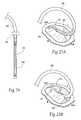
- the leaflet commissuresare designated in FIG. 4 and in other Figures as CP (denoting the posterior commissure) and CA (denoting the anterior commissure).
- Valve malfunctioncan result from the chordae tendinea (the chords) becoming stretched, and in some cases tearing. When a chord tears, the result is a leaflet that flails. Also, a normally structured valve may not function properly because of an enlargement of or shape change in the valve annulus. This condition is referred to as a dilation of the annulus and generally results from heart muscle failure. In addition, the valve may be defective at birth or because of an acquired disease.
- mitral valve dysfunctioncan occur when the leaflets do not coapt at peak contraction pressures.
- FIG. 5shows, the coaptation line of the two leaflets is not tight at systole. As a result, an undesired back flow of blood from the left ventricle into the left atrium can occur. This condition is called regurgitation.
- the leafletsdo not form a tight coaptation junction because the dimensions of the mitral valve annulus, measured from commissure to commissure—CP to CA—and/or septal to lateral—S to L—change. The changed dimensions no longer create the anatomic shape and tension in which the leaflets coapt at peak contraction pressures.
- the unhealthy annulusis dilated and, in particular, the septal-to-lateral distance is increased.
- the shape and tension defined by the annulusbecomes less oval (see FIG. 4 ) and more round (see FIG. 6 ). This condition is called dilation.
- the shape and tension conducive for coaptation at peak contraction pressuresprogressively deteriorate. Instead, at peak contraction pressures, the leaflets do not coapt completely, and a gap forms between the leaflets. During systole, regurgitation can occur through this gap.
- the ratio between the commissure distance and septal-to-lateral distancebears a relationship to the effectiveness of leaflet coaptation. If the septal-to-lateral distance increases, the ratio changes, and when the ratio reaches a certain value, regurgitation or the likelihood of regurgitation is indicated.
- Mitral valve regurgitationcan be an acute or chronic condition. It is sometimes called mitral insufficiency.
- diuretics and/or vasodilatorscan be used to help reduce the amount of blood flowing back into the left atrium.
- An intra-aortic balloon counterpulsation deviceis used if the condition is not stabilized with medications.
- surgery to repair or replace the mitral valveis often necessary.
- annuluscan be reshaped with annular or peri-annular rings or similar ring-like devices.
- the repair devicesare typically secured to the annulus and surrounding tissue with suture-based fixation.
- the repair devicesextend over the top and over much or all of the circumference of the annulus and leaflet surfaces.
- a physicianmay decide to replace an unhealthy mitral valve rather than repair it.
- Invasive, open heart surgical approachesare used to replace the natural valve with either a mechanical valve or biological tissue (bioprosthetic) taken from pigs, cows, or horses.
- the inventionprovides devices, systems and methods that reshape a valve annulus.
- the devices, systems, and methodsinclude an implant that is sized and configured to rest near or within the leaflet commissures of a heart valve annulus. In use, the implant contacts and outwardly displaces tissue to reshape the heart valve annulus.
- the implantin use, may restore to the heart valve annulus and leaflets a more effective anatomic shape and tension. The more normal anatomic shape and tension are conducive to coaptation of the leaflets during systole, which, in turn, reduces regurgitation.
- the implantrestores function to the valve, without surgically cinching, resecting, and/or fixing in position large portions of a dilated annulus, or without the surgical fixation of ring-like structures.
- FIG. 1is a perspective, anterior anatomic view of the interior of a healthy heart.
- FIG. 2is a superior anatomic view of the interior of a healthy heart, with the atria removed, showing the condition of the heart valves during diastole.
- FIG. 3is a superior anatomic view of the interior of a healthy heart, with the atria removed, showing the condition of the heart valves during systole.
- FIG. 4is a superior anatomic view of a healthy mitral valve during systole, showing the leaflets properly coapting.
- FIG. 5is a superior anatomic view of the interior of a heart, with the atria removed, showing the condition of the heart valves during systole, and further showing a dysfunctional mitral valve in which the leaflets are not properly coapting, causing regurgitation.
- FIG. 6is a superior anatomic view of a disfunctional mitral valve during systole, showing that the leaflets are not properly coapting, causing regurgitation.
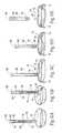
- FIG. 7Ais a side perspective view of an elastic implant sized and configured to rest within or near the leaflet commissures of a dysfunctional heart valve annulus to reshape the annulus and improve leaflet coaptation.
- FIGS. 7B to 7Eare side perspective views of illustrative alternative configurations of the elastic implant shown in FIG. 7A .
- FIG. 8is a side anterior anatomic view of a mitral valve annulus in which the elastic implant shown in FIG. 7A has been implanted.
- FIG. 9is a superior anatomic view of a mitral valve in which the elastic implant shown in FIG. 7A has been implanted, showing the implant stretching the commissures to restore leaflet coaptation.
- FIG. 10is a side perspective view of another embodiment of an elastic implant sized and configured to rest within or near the leaflet commissures of a dysfunctional heart valve annulus to reshape the annulus and restore leaflet coaptation, the implant defining a closed annular structure.
- FIG. 11is a perspective anatomic view, taken from an anterior and slightly superior viewpoint, of a mitral valve in which the elastic implant of the type shown in FIG. 10 has been implanted, showing the implant stretching the commissures to restore leaflet coaptation, and also showing the implant as hugging the annulus.
- FIG. 12is a perspective anatomic view, taken from an anterior and slightly superior viewpoint, of a mitral valve in which the elastic implant of the type shown in FIG. 10 has been implanted, showing the implant stretching the commissures to restore leaflet coaptation, and also showing the implant as rising above the annulus.
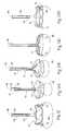
- FIGS. 13A to 13Care side perspective views of illustrative embodiments of an elastic implant sized and configured to rest within or near the leaflet commissures of a dysfunctional heart valve annulus to reshape the annulus and restore leaflet coaptation, the implant defining an open annular structure.
- FIGS. 13D and 13Eare side perspective views of illustrative embodiments of an elastic implant sized and configured to rest within or near the leaflet commissures of a dysfunctional heart valve annulus to reshape the annulus and restore leaflet coaptation, the implant defining an open annular structure that can be optionally closed.
- FIG. 14is a side perspective view of an elastic implant of the open annular type shown in FIGS. 13D and 13E , showing how the mechanical characteristics of the implant can be varied along its structure, surface area, and interface with the tissue.
- FIG. 15Ais a side perspective view of another embodiment of an elastic implant sized and configured to rest within or near the leaflet commissures of a dysfunctional heart valve annulus to reshape the annulus and restore leaflet coaptation, the implant defining a closed annular structure that can be symmetrically folded upon itself.
- FIG. 15Bis a side view of the implant shown in FIG. 15A when folded upon itself.
- FIG. 15Cis a perspective anatomic view, taken from an anterior and slightly superior viewpoint, of a mitral valve in which the elastic implant of the type shown in FIG. 15A has been implanted, showing the implant stretching the commissures to restore leaflet coaptation, and also showing the implant as hugging the annulus.
- FIG. 15Dis a side perspective view of another embodiment of an elastic implant sized and configured to rest within or near the leaflet commissures of a dysfunctional heart valve annulus to reshape the annulus and restore leaflet coaptation, the implant defining a closed annular structure that can be asymmetrically folded upon itself.
- FIG. 15Eis a perspective anatomic view, taken from an anterior and slightly superior viewpoint, of a mitral valve in which the elastic implant of the type shown in FIG. 15D has been implanted, showing the implant stretching the commissures to restore leaflet coaptation, and also showing the implant as hugging the annulus.
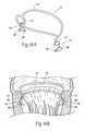
- FIG. 16Ais a side perspective view of an elastic implant of the type shown in FIG. 10 , showing an illustrative embodiment of tab structures that serve to anchor and stabilize the implant in an annulus.
- FIG. 16Bis a side anterior anatomic view of a mitral valve annulus in which the elastic implant shown in FIG. 16A has been implanted.
- FIG. 17Ais a side perspective view of an elastic implant of the type shown in FIG. 10 , showing an illustrative embodiment of multiple contact structures that serve to anchor and stabilize the implant in an annulus.
- FIG. 17Bis a side anterior anatomic view of a mitral valve annulus in which the elastic implant shown in FIG. 17A has been implanted.
- FIGS. 18A and 18Bare side perspective views of an elastic implant of the type shown in FIG. 10 , showing illustrative embodiments of frictional struts that serve to anchor and stabilize the implant in an annulus.
- FIG. 19is a side perspective view of an elastic implant of the type shown in FIG. 10 , showing an illustrative embodiment of tissue in-growth surfaces that serve to anchor and stabilize the implant in an annulus.
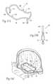
- FIGS. 20A and 20Bare, respectively, a side perspective view and an anatomic view (when implanted) of an elastic implant sized and configured to rest within or near the leaflet commissures of a dysfunctional heart valve annulus to reshape the annulus and restore leaflet coaptation and also showing the implant as rising significantly above the annulus.
- FIGS. 20C and 20Dare, respectively, a side perspective view and an anatomic view (when implanted) of an elastic implant sized and configured to rest within or near the leaflet commissures of a dysfunctional heart valve annulus to reshape the annulus and restore leaflet coaptation, and showing the presence of one rail that hugs the annulus and another rail that rises above the implant to serve as a mechanism that anchors and stabilizes the implant in the annulus.
- FIG. 21is a side elevation view of a tool for implanting an elastic implant in a valve annulus in a open heart surgical procedure to reshape the annulus and restore leaflet coaptation.
- FIGS. 22A to 22Fdiagrammatically show a method of using the tool shown in FIG. 21 to install an elastic implant in a valve annulus to reshape the annulus and restore leaflet coaptation.
- FIGS. 23A to 23Cdiagrammatically show a method of gaining intravascular access to the left atrium for the purpose of deploying a delivery catheter to place an implant in a valve annulus to reshape the annulus and restore leaflet coaptation.
- FIG. 24is a side elevation view of the distal end of the implant delivery catheter shown in FIG. 23C , showing an elastic implant of the type shown in FIG. 10 collapsed in a sleeve for deployment into the left atrium in the manner shown in FIGS. 23A to 23C .
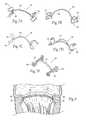
- FIGS. 25A to 25Eare diagrammatic perspective views of a method for manipulating the distal end of the implant delivery catheter shown in FIG. 24 to deploy an elastic implant of the type shown in FIG. 10 into a valve annulus to reshape the annulus and restore leaflet coaptation.
- FIG. 26Ais a side view of the distal end of the implant delivery catheter of the type shown in FIG. 23C , showing an elastic implant of the type shown in FIG. 10 collapsed in a sleeve for deployment into the left atrium in the manner shown in FIGS. 23A to 23C , also and showing the presence of a guide wire loop to aid in the deployment.
- FIGS. 27A to 27Iare diagrammatic views of a method for deploying an elastic implant of the type shown in FIG. 10 into a valve annulus with the aid of a guide wire loop to reshape the annulus and restore leaflet coaptation.
- FIGS. 28A and 28Bare perspective view of elastic implants of the type shown in FIGS. 13B to 13E , showing the tethering of such implants to one or more wire loops to aid in their deployment into a valve annulus to reshape the annulus and restore leaflet coaptation.
- FIG. 29is a side view of the distal end of the implant delivery catheter of the type shown in FIG. 23C , showing a symmetrical foldable elastic implant of the type shown in FIG. 15A folded and collapsed in a sleeve for deployment into the left atrium in the manner shown in FIGS. 23A to 23C .
- FIGS. 30A to 30Dare diagrammatic views of a method for manipulating the distal end of the implant delivery catheter shown in FIG. 29 to deploy a symmetrically folded and collapsed elastic implant of the type shown in FIG. 15A into a valve annulus to reshape the annulus and restore leaflet coaptation.
- FIGS. 31A to 31Eare diagrammatic views of a method for manipulating the distal end of the implant delivery catheter shown in FIG. 29 to deploy an asymmetrically folded and collapsed elastic implant of the type shown in FIG. 15D into a valve annulus to reshape the annulus and restore leaflet coaptation.
- FIG. 32is a side view of the distal end of the implant delivery catheter of the type shown in FIG. 23 C, showing a symmetrical foldable elastic implant of the type shown in FIG. 15A tethered to a guide wire loop to aid in its implantation into a valve annulus to reshape the annulus and restore leaflet coaptation.
- FIGS. 33A to 33Dare diagrammatic views of a method for manipulating the distal end of the implant delivery catheter shown in FIG. 32 to deploy a symmetrically folded and collapsed elastic implant of the type shown in FIG. 15A into a valve annulus with the aid of a guide wire loop to reshape the annulus and restore leaflet coaptation.
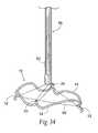
- FIG. 34is a side elevation view of the distal end of the implant delivery catheter of the type shown in FIG. 23C , showing a symmetrical foldable elastic implant of the type shown in FIG. 15A tethered to two guide wire loops to aid in its implantation into a valve annulus to reshape the annulus and restore leaflet coaptation.
- FIGS. 35 and 36A to 36Dare diagrammatic views of a method for manipulating the distal end of the implant delivery catheter to deploy a symmetrically folded and collapsed elastic implant of the type shown in FIG. 15A into a valve annulus with the aid of a separate guide wires to reshape the annulus and restore leaflet coaptation.
- FIGS. 37A to 37Care diagrammatic views of the deployment a symmetrically folded and collapsed elastic implant of the type shown in FIG. 15A into a valve annulus with the aid of a wrapper or bag to reshape the annulus and restore leaflet coaptation.
- FIG. 38is a side perspective view of a plastically deformable implant sized and configured to be expanded in situ to rest within or near the leaflet commissures of a dysfunctional heart valve annulus to reshape the annulus and restore leaflet coaptation.
- FIGS. 39A to 39Care diagrammatic views of the deployment of a plastically deformable implant of the type shown in FIG. 38 into a valve annulus with the aid of a mechanical expansion device.
- FIGS. 40A to 40Care diagrammatic anatomic views of the deployment of a plastically deformable implant of the type shown in FIG. 38 into a valve annulus with the aid of a balloon expansion device.
- FIG. 41is a diagrammatic view of a non-compliant balloon deployed into a valve annulus for the purpose of assessing the size and mechanical properties of an implant for the annulus.
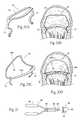
- FIG. 42is a side perspective view of a multi-functional elastic implant sized and configured to rest within or near the leaflet commissures of a dysfunctional heart valve annulus to reshape the annulus and restore leaflet coaptation as well serve as a neo-leaflet to either replace or supplement a damaged heart valve leaflet.
- FIGS. 43 and 44are side perspective views of a multi-functional elastic implants sized and configured to rest within or near the leaflet commissures of a dysfunctional heart valve annulus to reshape the annulus and restore leaflet coaptation as well serve as a leaflet retainer to prevent a native valve leaflet from being pushed into the atrium upon ventricular contraction.
- FIGS. 45 to 47are side perspective views of a multi-functional elastic implants sized and configured to rest within or near the leaflet commissures of a dysfunctional heart valve annulus to reshape the annulus and restore leaflet coaptation as well serve as a leaflet retainer to prevent a native valve leaflet from being pushed into the atrium upon ventricular contraction, the implants also including a framework that serves to help position and secure the implant in situ.
- FIGS. 7A and 8show an implant 10 sized and configured to rest within or near a heart valve annulus.
- the implantis shown in a mitral valve, and, in this arrangement, extends along the major (i.e., longest) axis above and/or along the valve annulus.
- the implant 10is sized and shaped so that, in use, it applies a mechanical force along the major axis.
- the mechanical forceserves to outwardly displace tissue (i.e., to displace tissue away from the center of the annulus) to reshape the annulus.
- the mechanical forceserves to lengthen the long axis of the annulus and, in doing so, can reactively shorten in the minor (i.e.
- the axes affectedmay not be the “major” and “minor” axes, due to the surrounding anatomy.
- the mechanical force applied by the implant 10restores to the heart valve annulus and leaflets a more normal anatomic shape and tension (see FIG. 9 ).
- the more normal anatomic shape and tensionare conducive to coaptation of the leaflets during systole, which, in turn, reduces regurgitation.
- the implant 10restores normal function to the valve, without surgically cinching, resecting, and/or fixing in position large portions of a dilated annulus or leaflets, or without the surgical fixation of ring-like structures.
- the implant 10lends itself to delivery to a targeted heart valve site by catheter-based, intravascular techniques, under image guidance.
- Image guidanceincludes but is not limited to fluoroscopy, ultrasound, magnetic resonance, computed tomography, or combinations thereof.
- the implant 10can be delivered using conventional open heart surgical techniques or by thorascopic surgery techniques.
- the implant 10is made—e.g., by bending, shaping, joining, machining, molding, or extrusion—from a biocompatible metallic or polymer material, or a metallic or polymer material that is suitably coated, impregnated, or otherwise treated with a material to impart biocompatibility, or a combination of such materials.
- the materialis also desirably radio-opaque to facilitate fluoroscopic visualization.
- the implant 10includes a pair of struts 12 joined by an intermediate rail 14 .
- the struts 12are sized and configured to rest at or near the leaflet commissures. It should be appreciated that the leaflet commissures may not, and typically are not, situated at geometrically opposite sides of the annulus (although for the purpose of illustration, they are shown that way in the Figures).
- the position of the struts 12can be selected to conform to an asymmetric morphology of the annulus, as is later described in connection with FIGS. 13A and 13B .
- the rail 14spans the struts 12 .
- the rail 14(like the struts 12 ) can take various shapes and have various cross-sectional geometries.
- the rail 14 (and/or the struts 12 )can have, e.g., a generally curvilinear (i.e., round or oval) cross-section, or a generally rectilinear cross section (i.e., square or rectangular), or combinations thereof.
- the implantis “elastic.”
- the rail 14is sized and configured to possess a normal, unloaded, shape or condition (shown in FIG. 7A ), in which the rail 14 is not in compression and the struts 12 are spaced apart farther than the anterior commissure to posterior commissure dimension of the targeted heart valve annulus.
- the material of the implantis selected to possess a desired spring constant.
- the spring constantimparts to the rail 14 the ability to be elastically compressed out of its normal, at rest condition, in response to external compression forces applied at the struts.
- the rail 14is sized and configured to assume an elastically loaded, in compression condition, during which the struts 12 are spaced apart a sufficiently shorter distance to rest in engagement with tissue at or near the leaflet commissures (see FIG. 8 ).
- the rail 14When in its elastically loaded, compressed condition (see FIG. 9 ), the rail 14 exerts opposing forces to the tissues at or near the commissures through the struts 12 , tending to outwardly displace tissue and stretch the annulus along its major axis, which also typically stretches apart the leaflet commissures, shortens the minor axis, and/or reshapes surrounding anatomic structures.
- the implantthereby reshapes the valve annulus toward a shape more conducive to leaflet coaptation.
- An elastic implantcan be made, e.g., from superelastic alloy, such that the implant can be elastically straightened and/or folded to fit within a catheter or sheath during deployment, and will regain its shape upon deployment (this characteristic will be described in greater detail later).
- the elasticity of the implant 10 itself, along with the elasticity of the valve tissue,ensure that the implant 10 can be positioned in the valve under a state of net compression and thus remain anchored without the use of sutures, adhesives, or other fixation materials, i.e. which is called compressive anchoring.
- the implant 10may itself deform elastically, although not necessarily so, but the characteristic of the implant 10 being elastically deformable may help to maintain compressive anchoring. If the implant 10 does not deform elastically or does so only slightly, the implant 10 relies on tissue elasticity to keep the implant anchored.
- the struts 12may carry other structures or mechanisms 16 to further enhance the anchorage and stabilization of the implant in the heart valve annulus.
- the mechanisms 16may be located below the plane of the annulus, to engage infra-annular heart tissue adjoining the annulus in the ventricle, and/or be located at or above the plane of the annulus, to engage tissue on the annulus or in the atrium.
- the spring constant of the implantmay be selected to be greater than the spring constant of adjoining tissue.
- the spring constant of the implantmay be selected to approximate the spring constant of adjoining tissue, thereby providing compliance to allow the implant 10 to adapt to tissue morphology during use.
- the spring constant of the implant 10may vary along the length of the rail 14 , so that some portions of the rail 14 are stiffer or more compliant than other portions of the rail 14 .
- the implant 10may be formed from a plastically deformable material.
- the implant 10is manufactured in a normally collapsed condition.
- the implant 10is expanded in situ into an in use condition within the annulus, e.g., by an inflatable body (e.g., balloon) or by a suitable mechanical device (e.g., a scissorjack).
- an inflatable bodye.g., balloon
- a suitable mechanical devicee.g., a scissorjack
- An elastic implant 10 having the characteristic just describedcan take various forms and configurations. The following describes various illustrative arrangements.
- the implants 10 in FIGS. 7A to 7Ccomprise a single rail 14 spanning the distance between the struts 12 .
- an implant 10can include more than a single rail 14 , imparting a normally closed, annular shape to the implant.
- an implant 10 of this typecan be conveyed to an implantation site, e.g., within a catheter or sheath, in a collapsed, straightened condition (with the rails 14 collapsed side-by-side). When deployed from the catheter or sheath, the implant 10 springs open to assume the normally closed, annular shape shown in FIGS. 7D and 10 .
- the implant 10includes two rails 14 spanning the struts 12 .
- the shape and configuration of the rails 14can be varied, depending upon the desired orientation of the rails 14 with respect to the annulus itself.
- the two rails 14are shaped and configured so that, when implanted, the rails 14 follow the circumferential path of the annulus and rest in generally the same plane as the annulus.
- This implantcan be characterized as “hugging” the annulus.
- the two rails 14are shaped and configured so that, when implanted, the rails 14 follow the circumferential path of the annulus, and also rise above the plane of the annulus.
- This implant 10can be characterized as “riding above” the annulus.
- An implant 10 that “rides above” the annuluscan extend close to the annulus (as FIG. 12 shows) or rise significantly above the annulus toward the dome of the atrium as FIGS. 20A and 20B show.
- an implant 10can include a rail 14 A that hugs the annulus and a rail 14 B that rides above the annulus and contacts a heart wall, serving as a mechanism 16 that orients and stabilizes the implant.
- FIGS. 13A to 13Eshow, the rails 14 of a given annular implant 10 can be interrupted to impart a normally open annular (“hemi”) shape to the implant 10 .
- an implant 10 of this typealso can be conveyed to an implantation site, e.g., within a catheter or sheath, in a collapsed, straightened condition, and then deployed to assume the open, annular shape shown in FIGS. 13A to 13E .
- the open annular shapeis configured so that, when implanted, the implant 10 hugs the annulus.
- the open annular shapeis configured so that, when implanted, the implant rides above the annulus.
- FIGS. 13C and 13Dshow another style of open annular implant, one that hugs the annulus ( FIG. 13C ) and the other that rides above the annulus ( FIG. 13D ).
- the interrupted rail 14includes interlocking hooks 18 that can be coupled, if desired, to close the annulus of the implant 10 (see FIG. 13E ).
- the interlocked implant 10is configured to ride above the annulus.
- the struts 12need not be placed at diametrically opposite sides of the rail or rails 14 .
- the commissures of a given valve annulusmay not be at geometrically opposite sides of the annulus. Accordingly, the position of the struts 12 may be selected to conform to an asymmetric morphology of the annulus.
- the struts 12may be used to simply locate the implant 10 in the valve, imparting little or no force on their own. In this arrangement, the annulus reshaping forces emanate from the rail or rails 14 above the commissures.
- the implantpossesses a spring constant that approximates the spring constant of tissue, making the implant more accommodating to the movement of the tissue.
- a given rail or rails 14can include undulations or the like to impart regions having different spring constants and/or mechanical properties along the length of the rail 14 .
- the cross-sectional width and/or thickness and/or geometry of a given rail 14need not be uniform, but can vary along the length of the rail 14 to impart regions of different spring constants and/or mechanical properties.
- the region of the continuous rail 14 between the asymmetrically placed struts 12may be thickened or thinned to impart different mechanical properties to achieve the desired shape changing objectives.
- the implants 10 shown in FIGS. 15A to 15Ecomprise more than a single rail 14 , imparting a normally closed, annular shape to the implant.
- the rails 14 of the implants 10 shown in FIGS. 15A to 15Einclude cusps 20 .
- the cusps 20permit the implants to be resiliently folded along their minor (transverse axis) axis—with the cusps 20 occupying the fold—without permanently deforming the implant (see FIG. 15B ).
- an implant 10 of this typecan be conveyed to an implantation site, e.g., within a catheter or sheath, in a folded as well as collapsed condition, and then deployed to assume the normally closed, annular shape shown in FIG. 15A , as FIG. 15C shows.
- the shape and configuration of the rails 14can be varied so that, when deployed, the implant hugs the annulus or rides above the annulus.
- FIG. 15Athe cusps 20 are symmetric, being formed on each rail 14 equidistant to the struts 12 .
- the struts 12are also shown symmetric as to height above the rail 14 .
- FIG. 15Dshows that the cusps 20 need not be symmetric in either respect. As will be described in greater detail later, this asymmetry permits a stepwise, staggered deployment of the implant, in which the parts of the implant are deployed one at a time in succession—e.g., one strut, then one cusp, then another strut, and then the other cusp—until the implant assumes the closed, annular shape shown in FIG. 15D , as FIG. 15E shows.
- the struts 12can include other structures or mechanisms 16 to further enhance the anchorage and stabilization of the implant in the heart valve annulus.
- These structures or other mechanisms 16can comprise, e.g., loops, pads, barbs, vertical legs, or circumferential legs, or other anchoring structures below, at, and/or above the valve plane.
- the structures and mechanisms 16desirably increase the surface area of contact between the struts 12 and tissue adjoining the annulus.
- the structures and mechanism 16desirably rely solely or partly on the valve and neighboring anatomic structures to anchor and fix the position of the implant in the annulus and resist its migration out of the annulus. Implant fixation can also assist in the achieving the desired coaptation of the leaflets and to resist upward movement or eversion of the leaflets during the cardiac cycle.
- the rails 14carry four struts 12 , two supra-annular (contacting tissue on the atrial side of the valve) and two infra-annular (contacting tissue on the ventricular size of the valve).
- the struts 12are separated by a thin spine that curves away from the struts 12 to avoid contact with the commissures themselves, so as not to interfere with the opening and closing of the valve.
- the struts 12may be cushioned to increase traction, decrease erosion, and improve their interaction with the valve annulus.
- the struts 12may be coated, covered, or impregnated with a tissue growth promoting material.
- the rails 14 spanning the struts 12functions to exert compressive forces on the annulus.
- the struts 12are secured by the compression forces created by the rail's interaction with the valve annulus. The struts 12 assure that the implant is positioned correctly in situ, because they will only seat when positioned at or near the commissures of the valve.
- the struts 12may be sized and shaped in various ways.
- FIGS. 7B, 7C, and 7Dshow various embodiments with alternative designs for the struts 12 .
- the supra-annular struts 12are somewhat larger than the infra-annular struts 12 to improve the anatomical fit of the device in situ.
- the struts 12can carry flat infra-annular tissue contacting pads 26 , located below the plane of the valve annulus.
- the pads 26rest on outwardly bowed extensions below the commissures, applying holding forces upon the heart walls.
- the pads 26can take the form of flat surfaces, as FIGS. 16A and 16B show.
- Tissue penetrating barbs 28may enhance the effect of the compression forces to fix the location of the implant.
- the struts 12can extend in an undulating fashion below the plane of the valve annulus, to create a series of infra-annular contact surfaces 30 between the implant and the heart walls below and adjoining the annulus.
- the series of contact surfaces 30increase the points of contact between the implant and tissue below the annulus. These multiple points of contact 30 are additive to the contact between the implant and tissue at or near the commissures themselves.
- additional struts and/or barbs or similar anchoring surfacesare not shown associated with the contact surfaces, but they could be included, if desired.
- the implantcan include infra-annular frictional struts 32 located below the level of the annulus.
- the infra-annular frictional struts 32engage tissue of the heart walls below and adjoining the annulus.
- the struts 32resist migration of the implant out of the annulus.
- the frictional struts 32can be placed in a single level immediately below the commissures, or (as FIG. 18B shows) the struts 32 can be arranged in multiple levels below the commissures.
- the struts 12 and/or the rails 14can include tissue in-growth surfaces 34 .
- the surfaces 14provide an environment that encourages the in-growth of neighboring tissue on the implant. Once in-growth occurs, the implant 10 becomes resistant to migration or dislodgment from the annulus. Conventional in-growth materials such as polyester fabric can be used.
- fixation mechanism or structuremay, if desired, be combined with an adhesive or like material to further secure the implant.
- the various implants as just describedlend themselves to implantation in a heart valve annulus in various ways. They can be implanted, e.g., in an open heart surgical procedure. Alternatively, they can be implanted using catheter-based technology via a peripheral venous access site, such as in the femoral or jugular vein or femoral artery, or alternatively by thorascopically through the chest or by means of other surgical access through the right atrium.
- FIG. 21shows a tool 40 for deploying an elastic implant 10 of the type generally described in an annulus of a heart valve in an open surgical procedure.
- FIGS. 22A to 22Fdiagrammatically show the steps of an open surgical procedure for deploying the implant 10 in a mitral valve annulus using the tool 40 shown in FIG. 21 .
- the tool 40includes a scissors-action mechanism 42 comprising an operating end 46 and a handle end 48 .
- the operating end 46includes prongs 44 that can be moved apart and together by manipulation of the handle end 48 (see FIGS. 22A and 22B ).
- the prongs 44are sized and configured to mate with deployment apertures 50 formed on the struts 12 of the implant 10 (shown in FIG. 21 ).
- the deployment apertures 50are also shown in the implants in preceding FIGS. 10 to 19 , which can be likewise be deployed using the tool 40 .
- the scissors-action mechanism 42is manipulated to spread the prongs 44 apart (see FIGS. 22A and 22B ), so that they can be mated in the apertures 50 of the implant 10 .
- the scissors-action mechanism 44is manipulated to bring the prongs 44 together, thereby applying force to the struts 12 to place the implant 10 in a compressed condition (see FIG. 22C ).
- the tool 40 and implant 10are introduced through an open surgical approach into the left atrium.
- the tool 40places the implant 10 within the mitral valve annulus (see FIG. 22D ).
- the annulusis shown to have a dimension of D 1 .
- This dimension D 1is not conducive to leaflet coaptation, and regurgitation is occurring. It is the purpose of the surgical procedure to repair this dysfunction by reshaping the annulus with the implant 10 .
- the scissors-action mechanism 42is manipulated to spread the prongs 44 apart until the struts 12 of the implant 10 rest within or near the commissures of the mitral valve (see FIG. 22E ). At this point in the procedure, the dimension D 1 of the annulus remains unchanged.
- the tool 40is withdrawn, freeing the prongs 12 from the apertures 50 (see FIG. 22F ).
- the elastic unloading of the implant 10displaces and spreads the valve tissue apart, achieving a new dimension D 2 for the annulus, which is larger than D 1 .
- the new dimension D 2is conducive to leaflet coaptation.
- the implant 10has reshaped the annulus to restore valve function.
- FIGS. 23 to 25show a representative embodiment of a percutaneous catheter-based linear deployment of an unfolded elastic implant 10 of the type shown in FIGS. 7 to 14 .
- Percutaneous vascular accessis achieved by conventional methods into the femoral or jugular vein.
- a catheter 52is steered through the vasculature into the right atrium.
- a needle cannula 54 carried on the distal end of the catheteris deployed to pierce the septum between the right and left atrium.
- a guidewire 56is advanced trans-septally through the needle catheter 52 into the left atrium.
- the first catheter 52is withdrawn, and (as FIG. 23C shows) under image guidance, an implant delivery catheter 58 is advanced over the guidewire 56 into the left atrium into proximity with the mitral valve.
- the implant delivery catheter 58can be deployed trans-septally by means of surgical access through the right atrium.
- the implant delivery catheter 58carries a sheath 60 at its distal end (see FIG. 24 ).
- the sheath 60encloses an elastic implant 10 of a type shown in FIGS. 7 to 14 .
- the implant 10is constrained in a collapsed, straightened condition within the sheath, as FIG. 24 shows.
- the sheath 60can be sized and configured to be withdrawn (e.g., by sliding it proximally), to free the implant 10 . Free of the sheath 60 , the elastic implant 10 will expand.
- a flexible push rod 62 in the catheter 58can be used to expel the implant 10 from the sheath 60 , with the same result.
- the strut 12 on the trailing end of the implant 10is folded within the sheath 60 to reduce the collapsed profile and facilitate the expansion of the implant 10 once free from the sheath 60 .
- FIG. 25Ashows, under image guidance, the strut 12 on the leading end of the implant 10 is freed from the sheath 60 and seated retrograde in the posterior commissure of the valve annulus. Anchoring structures or mechanisms associated with the strut are also placed into desired contact with adjoining tissue below and/or above the plane of the annulus.
- FIG. 25Bshows, the delivery catheter 58 maintains force on the leading strut 12 within the posterior commissure, as the sheath 60 is withdrawn in line with the coaptation line in a posterior-to-anterior direction along the coaptation line. As shown in FIG.
- the delivery catheter 58may need to dip down retrograde below the plane of the leaflets to maintain sufficient force on the leading end of the implant while the trailing end is freed from the sheath 60 .
- the delivery catheter 58may be sized and configured to have the column strength sufficient to maintain force on the leading strut without passage below the leaflet plane.
- the elastic implant 10shapes and seats (as FIGS. 25B /C and 25 D shows), until the trailing strut 12 unfolds and seats within the anterior commissure (see FIG. 25E ).
- the implantcan also be positioned or repositioned under image guidance within the left atrium using a catheter-deployed grasping instrument.
- FIGS. 26 and 27A to 27Ishow another embodiment of an implant delivery catheter 58 that can be used to deploy a folded elastic implant 10 of the type shown in FIGS. 7 to 14 within the left atrium.
- the implant delivery catheter 58includes a sheath 60 that constrains the implant 10 in a collapsed, straightened condition for passage into the left atrium (see FIG. 26 ).
- the sheath 60is sized and configured to be withdrawn (e.g., by sliding it proximally), to free the implant for expansion within the left atrium, or a push rod 62 can be used to eject the implant from the sheath 60 .
- a push rod 62can be used to eject the implant from the sheath 60 .
- one or both strutscan be folded against the body of the implant within the sheath 60 .
- a metallic, fiber, or polymer guide wire 64is looped through the deployment apertures 50 on the struts 12 of the implant 10 prior to the insertion of the implant 12 into the sheath 60 .
- the legs of the resulting guide wire loop 66are passed out the proximal end of the sheath 60 for manipulation, as will now be described.
- the implant delivery catheter 58is introduced trans-septally into the left atrium in the manner previously described. With the distal end of the catheter 58 positioned above the valve annulus (see FIG. 27A ), and prior to withdrawal of the sheath 60 , both legs of the guide wire loop 66 are advanced distally in tandem through the sheath 60 to advance the loop 60 beyond the deployment apertures 50 and out the distal end of the sheath 60 .
- the guide wire loop 66desirably carries radio-opaque markers 68 to aid in fluoroscopic visualization.
- the markers 68identify a desired distance between them and the distal end of the sheath 60 , marking a space in which the implant 10 can freely expand without contacting tissue or anatomic structures within the atrium. Guided by the markers 68 , the loop 66 can be dropped into the annulus a desired distance beyond the distal end of the sheath 60 , as FIG. 27A shows.
- the sheath 60can be withdrawn to free the implant 10 for expansion (see FIG. 27B ). While tethered to the guide wire loop 66 , the implant 10 opens within the left atrium—first one strut, then the other—as the sheath 60 is withdrawn, as FIGS. 27C and 27D show.
- both legs of the guide wire loop 66can be advanced proximally in tandem through the sheath 60 (see FIG. 27E ).
- the wire loop 66applies force to the struts 12 and brings them together (see FIG. 27F ). This places the implant 10 in a compressed, elastically loaded condition. Proximal advancement of the legs of the wire loop 66 also draws the implant 10 in this condition snuggly against the distal end of the catheter 58 for greater control, as FIG. 27F shows.
- the catheter 58can be advanced under image guidance to place the implant 10 within the annulus. Manipulation of the catheter 58 will bring the struts of the implant into desired alignment. Subsequent distal advancement of the legs of the wire loop 66 (see FIG. 27H ) allows the struts of the implant 10 to be elastically unloaded and brought into contact with the surrounding tissue. Anchoring structures or mechanisms associated with the struts 12 can also be placed into desired contact with adjoining tissue below and/or above the plane of the annulus. The legs of the wire loop 66 can be manipulated to pull the struts 12 together and/or allow them to separate, until the desired orientation and tissue contact in and about the annulus are achieved.
- one leg of the wire loop 66can be pulled to release the implant from the guide wire 64 (see FIG. 27I ).
- the implant 10is allowed to fully unfold and seat within the annulus.
- a guide loop 66can be used to deploy open annular implants as well as closed annular implants. As shown in FIG. 28A , a single guide loop 66 can be threaded through an open annular implant 10 of the type shown in FIG. 13B . Or, as shown in FIG. 28B , two guide wire loops 66 A and 66 B can be threaded through an inter-locking implant of the type shown in FIGS. 13D and 13E . In this arrangement, the first guide wire loop 66 A can be manipulated to position the struts 12 of the implant within the annulus, as just described. The second guide wire loop 66 B can be separately manipulated to pull the rails 14 together for interlocking, once the struts rest in a desired manner in the commissures.
- FIGS. 15A to 15Eshow elastic implants 10 that can be folded about cusps 20 .
- the foldingallows the implant 10 to be conveyed into the left atrium within a sheath 60 of an implant delivery catheter 58 with a delivery profile that not only constitutes a side-to-side collapsed condition—which minimizes the delivery profile diameter—but also constitutes a lengthwise folded condition—which minimizes the delivery profile length.
- FIGS. 30A to 30Dillustrate the deployment of a symmetrically folded elastic implant 10 of the type shown in FIGS. 15A and 15B .
- the implant 10is constrained in a symmetrically folded and collapsed condition within the sheath 60 , as FIG. 30A shows.
- the struts 12form the leading end of the implant.
- a push rod 62 in the catheter 58includes a gripping mechanism 70 that holds the folded implant 10 by the cusps 20 .
- the push rod 62is advanced to expel the implant 12 from the sheath 60 , both struts 12 first.
- the folded implant 10is aligned with coaptation line generally equidistant from the commissures, with the struts 12 oriented to face the commissures (the delivery catheter 58 has been previously introduced trans-septally into the left atrium, as already described).
- Manipulating the push rod 62advances the implant 10 , both struts first, from the sheath 60 .
- Connecting the push rod 62 to the implant 10allows the implant 10 to be translated and rotated and retracted during deployment. Freed from the sheath 60 (see FIG. 30B ), the implant 10 begins to unfold along the cusps 20 , and the struts 12 draw apart toward the commissures.
- the implant 10Prior to release of the cusps 20 from the gripping mechanism 70 , the implant 10 can be manipulated to assure that anchoring structures or mechanisms associated with the strut are placed into desired contact with adjoining tissue below and/or above the plane of the annulus. The gripping mechanism 70 can then be activated (see FIG. 30D ), releasing the implant 10 .
- FIGS. 31A to 31Eillustrate the deployment of an asymmetrically folded elastic implant 10 of the type shown in FIGS. 15D and 15E .
- the implant 10is constrained in an asymmetrically folded and collapsed condition within the sheath 60 , as FIG. 31A shows.
- the gripping mechanism 70holds one, but not both of the cusps 20 . This is because the height of the cusps 20 above the rails 14 is also asymmetric.
- the gripping mechanism 70will couple to the taller cusp 20 .
- the push rod 62can be advanced to expel the implant 10 from the sheath 60 . Due to the asymmetry of the cusps 20 , one of the struts 12 is positioned for deployment before the other strut 12 . Also due to the asymmetry of the cusps 20 , the shorter cusp 20 is positioned for advancement out of the sheath 60 before the taller cusp 20 is released by the gripping mechanism 70 .
- FIG. 31Bshows, under image guidance, the folded and collapsed implant 10 is aligned with coaptation line near one of the commissures (the delivery catheter 58 has been previously introduced trans-septally into the left atrium, as already described).
- Manipulating the push rod 62advances the implant 10 from the sheath 60 .
- the leading strut 12is freed first (see FIG. 31B ) and placed against the adjacent commissure.
- the implant 10can be manipulated to assure that anchoring structures or mechanisms associated with the leading strut are placed into desired contact with adjoining tissue below and/or above the plane of the annulus. Further advancement of push rod 62 causes the implant 10 to unfold toward the opposite commissure.
- FIG. 31Cshows.
- the implant 10can be manipulated to assure that anchoring structures or mechanisms associated with the trailing strut 12 are placed into desired contact with adjoining tissue below and/or above the plane of the annulus. Further advancement of the push rod 62 frees the shorter cusp 12 from the sheath 60 , and the implant 10 springs open along this side (see FIG. 31D ). The gripping mechanism 70 can then be activated (see FIG. 31 ), releasing the taller cusp 12 . The implant 10 springs open in this direction. It can be seen that the asymmetry of the implant 10 make possible a step-wise deployment of the implant 10 , one component at a time, in the annulus.
- One or more guide loops 66 or tetherscan likewise be employed to assist in the deployment of folded elastic implants of either symmetric or asymmetric types.
- a metallic, fiber, or polymer guide wire 64can be looped through the deployment apertures on the struts of a folded symmetric or asymmetric implant 10 prior to the folding and insertion of the implant 10 into the sheath 60 .
- the legs of the resulting guide wire loop 66are passed out the proximal end of the sheath 60 for manipulation.
- both legs of the guide wire loop 66are advanced distally in tandem through the sheath 60 to advance the loop 66 beyond the deployment apertures and out the distal end of the sheath 60 .
- the loop 66is placed within the annulus.
- the push rod 62is manipulated to free the folded implant 10 for expansion (see FIG. 33B ).
- the implant 10opens while tethered to the guide wire loop 66 .
- the loop 66increases in diameter as the struts 12 expand apart.
- the perimeter of the loop 66will orient itself along the greatest dimension of the annulus—which is the distance between the commissures.
- the loop 66thereby orients the implant 10 with the coaptation line during implant 10 expansion.
- the legs of the loop 66guide the struts 12 to the commissures (as FIG. 33C shows).
- the implant 10is deployed in the annulus.
- the guide wire loop 66maintains control of the strut spacing within the commissures during implant expansion.
- the gripping mechanism 70can release the implant 10 .
- One leg of the wire loop 66can be pulled to release the implant 10 from the guide wire (see FIG. 33D ).
- the implant 10is allowed to fully unfold and seat within the annulus.
- a second guide wire loop 72can also be passed through apertures on the cusps 20 .
- This guide wire loop 72can be manipulated independently of the first guide wire loop 66 , to control deployment of the expanding implant 10 in the septal-to-lateral dimension. Simultaneous, although independent, control of the expanding implant 10 can be achieved by manipulation of the first guide wire 66 .
- separate metallic, fiber, or polymer guide wires 92can be individually threaded (without looping) through the deployment apertures on the struts of a folded symmetric or asymmetric implant 10 prior to the folding and insertion of the implant 10 into the sheath 60 (see FIG. 35 ).
- the separate guide wires 92are passed out the proximal end of the sheath 60 for manipulation.
- the implant delivery catheter 58is introduced trans-septally into the left atrium in the manner previously described, and prior to activation of the push rod 62 —the separate guide wires 92 are advanced distally in tandem through the sheath 60 and out the distal end of the sheath 60 . The ends of the wires 92 are placed within the annulus.
- the push rod 62is manipulated to free the folded implant 10 for expansion (see FIG. 36B ).
- the implant 10opens while tethered to the separate guide wires 92 .
- the guide wires 92will orient themselves along the major axis of the annulus—which is the distance between the commissures, to orient the implant 10 with the coaptation line during implant 10 expansion.
- the guide wires 92separately guide the respective struts 12 to the commissures (as FIG. 36C shows).
- the implant 10is deployed in the annulus.
- the guide wires 92maintain control of the strut spacing within the commissures during implant expansion.
- the gripping mechanism 70can release the implant 10 .
- the guide wires 92can be pulled to release the implant 10 from the guide wires (see FIG. 36D ).
- the implant 10is allowed to fully unfold and seat within the annulus.
- the foregoing embodimentsdemonstrate that the unfolding of an elastic implant 10 can be controlled during deployment in either the major axis dimension, or the minor axis (septal-to-lateral) dimension, or in both dimensions by means of guide wires.
- Other forms of restraining mechanismscan be used to control the unfolding of the implant 10 .
- the folded implant 10can be restrained within a bag or wrapper 76 as the implant 10 is advanced from the delivery sheath 60 .
- the bag or wrapper 76restricts expansion of the implant 10 beyond a selected point (e.g., 80% of full deployment), allowing the physician to attend to the important task of seating the struts in the commissures before the implant 10 fully opens across the annulus.
- a ripcord 78 coupled to the bag or wrapper 76can be pulled, to release the bag or wrapper 76 from the implant 10 (see FIG. 37C ).
- the implant 10Freed from the bag or wrapper 76 , the implant 10 completes its expansion, to achieve final shaping and seating within the annulus.
- One or more guide wirescan be used in combination with the bag or wrapper 76 .
- the bag or wrapper 76can alternatively be sized and configured to tear away as a result of the implant 10 expanding beyond a given point, without the use of a ripcord 78 or similar induced tearing mechanism.
- the implant 10can be enclosed within a shrink-wrap structure having a score line.
- the structureis sized and configured to restrain expansion of the implant 10 until the implant 10 is advanced outside of the delivery sheath beyond a given point, at which time the score line parts or the material strength of the structure is exceeded, to open and fully release the implant 10 .
- the implant 10may be formed from plastically deformable material (see FIG. 38 ).
- the implant 10includes struts and one or more rails, as previously described.
- the implant 10is deployed by an implant delivery catheter 58 into the left atrium in a normally collapsed condition.
- an implant delivery catheter 58can carry a mechanical expansion device 80 , such as a scissorjack or the like (see FIGS. 39A to 39C ), to expand the plastically deformable material of the implant 10 in situ within the annulus.
- an implant delivery catheter 58can carry an inflatable body 82 (e.g., balloon) (see FIGS. 40A to 40C ), to expand the implant 10 within the annulus.
- the plastically deformable implant 10stretches the annulus to achieve a desired major axis size. Once expanded, the plastically deformable implant 10 maintains the desired distance, thereby resisting contraction of the annulus.
- the plastically deformable implant 10may include other structures or mechanisms to further anchor and stabilize the implant 10 in the heart valve annulus.
- a heart valvesuch as a mitral valve and the neighboring anatomic structures are generally understood by medical professionals using textbooks of human anatomy along with their knowledge of the site and its disease or injury. Ranges of shapes and dimensions for a given implant are defined by the site to be treated. Precise dimensions for a given patient can be determined by X-ray, MRI, or CT scanning of the site to be treated prior to implantation of an implant.
- a physicianmay also ascertain the size and resistance for a given implant by the deployment of a non-compliant balloon gauge 84 in the targeted annulus, as shown in FIG. 41 .
- the balloon gauge 84can carry radio-opaque markers 86 so that dimensions of the annulus can be determined using imaging means and/or other forms of in situ visualization.
- the compliance and tension forces of the annuluscan also be physically measured, by sensing and quantifying the resistance the balloon gauge 84 encounters during expansion in the annulus. Based upon this data, and taking into account the physician's knowledge of the site and its disease or injury, a physician can select a desired size and mechanical properties for the implant.
- implants 10have described the context of reshaping a heart valve annulus.
- a given implant 10 having technical features suited for this functioncan also incorporate other technical features well suited for other functions.
- FIG. 42shows an annulus remodeling implant 10 in which the rails 14 are sized and configured to define a pseudo-annulus.
- a neoleaflet element 88comprising a fabric-covered bridge structure is coupled to the rails.
- the neoleaflet elementis sized and configured to occupy the space of at least a portion of a native heart valve leaflet to provide a one-way valve function.
- the one-way valve functionIn response to diastolic pressure, the one-way valve function assumed a valve opened condition within the pseudo-annulus.
- the one-way valve functionassumes a valve closed condition within the pseudo-annulus.
- the neoleaflet element 88serves to either repair or replace or supplement a damaged heart valve.
- FIGS. 43 and 44show an annulus remodeling implant 10 in which the rails 14 are sized and configured serve as a pseuedo-annulus.
- the implant 10includes a retaining structure 90 near or within the pseudo-annulus that is sized and shaped to overlay at least a portion of one or more native valve leaflets.
- the retaining structure 90retains a native valve leaflet during ventricular contraction, keeping the valve leaflet from being pushed into the atrium, i.e., eversion and/or prolapse.
- FIGS. 45 to 47shows an annulus remodeling implant 10 in which the rails further include a framework 38 (as previously described) to help position and secure the device in situ.
- the framework 38also includes as a leaflet retaining structure 90 , as just described.
Landscapes
- Health & Medical Sciences (AREA)
- Cardiology (AREA)
- Biomedical Technology (AREA)
- Engineering & Computer Science (AREA)
- Life Sciences & Earth Sciences (AREA)
- Veterinary Medicine (AREA)
- Heart & Thoracic Surgery (AREA)
- Animal Behavior & Ethology (AREA)
- General Health & Medical Sciences (AREA)
- Public Health (AREA)
- Oral & Maxillofacial Surgery (AREA)
- Vascular Medicine (AREA)
- Transplantation (AREA)
- Surgery (AREA)
- Pathology (AREA)
- Nuclear Medicine, Radiotherapy & Molecular Imaging (AREA)
- Medical Informatics (AREA)
- Molecular Biology (AREA)
- Prostheses (AREA)
- Surgical Instruments (AREA)
- Materials For Medical Uses (AREA)
- Magnetic Resonance Imaging Apparatus (AREA)
- Apparatus For Radiation Diagnosis (AREA)
- External Artificial Organs (AREA)
Abstract
Description
Claims (21)
Priority Applications (1)
| Application Number | Priority Date | Filing Date | Title |
|---|---|---|---|
| US12/462,956US9861475B2 (en) | 2000-09-20 | 2009-08-12 | Devices, systems, and methods for reshaping a heart valve annulus |
Applications Claiming Priority (8)
| Application Number | Priority Date | Filing Date | Title |
|---|---|---|---|
| US09/666,617US6893459B1 (en) | 2000-09-20 | 2000-09-20 | Heart valve annulus device and method of using same |
| PCT/US2002/031376WO2003028558A2 (en) | 2001-10-01 | 2002-10-01 | Methods and devices for heart valve treatments |
| US42944402P | 2002-11-26 | 2002-11-26 | |
| US42946202P | 2002-11-26 | 2002-11-26 | |
| US42970902P | 2002-11-26 | 2002-11-26 | |
| US10/677,104US20060106456A9 (en) | 2002-10-01 | 2003-10-01 | Devices, systems, and methods for reshaping a heart valve annulus |
| PCT/US2003/030831WO2004030569A2 (en) | 2002-10-01 | 2003-10-01 | Devices, systems, and methods for reshaping a heart valve annulus |
| US12/462,956US9861475B2 (en) | 2000-09-20 | 2009-08-12 | Devices, systems, and methods for reshaping a heart valve annulus |
Related Parent Applications (1)
| Application Number | Title | Priority Date | Filing Date |
|---|---|---|---|
| US10/677,104ContinuationUS20060106456A9 (en) | 2000-09-20 | 2003-10-01 | Devices, systems, and methods for reshaping a heart valve annulus |
Publications (2)
| Publication Number | Publication Date |
|---|---|
| US20090306622A1 US20090306622A1 (en) | 2009-12-10 |
| US9861475B2true US9861475B2 (en) | 2018-01-09 |
Family
ID=44585015
Family Applications (2)
| Application Number | Title | Priority Date | Filing Date |
|---|---|---|---|
| US10/677,104AbandonedUS20060106456A9 (en) | 2000-09-20 | 2003-10-01 | Devices, systems, and methods for reshaping a heart valve annulus |
| US12/462,956Active2027-01-31US9861475B2 (en) | 2000-09-20 | 2009-08-12 | Devices, systems, and methods for reshaping a heart valve annulus |
Family Applications Before (1)
| Application Number | Title | Priority Date | Filing Date |
|---|---|---|---|
| US10/677,104AbandonedUS20060106456A9 (en) | 2000-09-20 | 2003-10-01 | Devices, systems, and methods for reshaping a heart valve annulus |
Country Status (9)
| Country | Link |
|---|---|
| US (2) | US20060106456A9 (en) |
| EP (1) | EP1562522B1 (en) |
| JP (1) | JP2006501033A (en) |
| CN (1) | CN100553590C (en) |
| AT (1) | ATE418938T1 (en) |
| AU (2) | AU2003277116A1 (en) |
| CA (1) | CA2498030A1 (en) |
| DE (1) | DE60325634D1 (en) |
| WO (1) | WO2004030569A2 (en) |
Cited By (18)
| Publication number | Priority date | Publication date | Assignee | Title |
|---|---|---|---|---|
| EP2916771A1 (en)* | 2012-11-07 | 2015-09-16 | Medtentia International Ltd Oy | Medical device for a cardiac valve implant, and a metod of manufacturing the medical device |
| US10136985B2 (en) | 2014-07-17 | 2018-11-27 | Millipede, Inc. | Method of reconfiguring a mitral valve annulus |
| US10258466B2 (en) | 2015-02-13 | 2019-04-16 | Millipede, Inc. | Valve replacement using moveable restrains and angled struts |
| US20190183645A1 (en)* | 2015-12-10 | 2019-06-20 | Mvrx, Inc. | Devices, Systems, and Methods for Reshaping a Heart Valve Annulus |
| US10335275B2 (en) | 2015-09-29 | 2019-07-02 | Millipede, Inc. | Methods for delivery of heart valve devices using intravascular ultrasound imaging |
| WO2019222694A1 (en)* | 2018-05-18 | 2019-11-21 | Elixir Medical Corporation | Methods and devices for heart valve repair |
| US10543088B2 (en) | 2012-09-14 | 2020-01-28 | Boston Scientific Scimed, Inc. | Mitral valve inversion prostheses |
| US10548731B2 (en) | 2017-02-10 | 2020-02-04 | Boston Scientific Scimed, Inc. | Implantable device and delivery system for reshaping a heart valve annulus |
| US20200146854A1 (en)* | 2016-05-16 | 2020-05-14 | Elixir Medical Corporation | Methods and devices for heart valve repair |
| US10849755B2 (en) | 2012-09-14 | 2020-12-01 | Boston Scientific Scimed, Inc. | Mitral valve inversion prostheses |
| US11253363B2 (en) | 2018-01-07 | 2022-02-22 | Jc Medical Inc. | Heart valve prosthesis |
| US11259923B2 (en) | 2013-03-14 | 2022-03-01 | Jc Medical, Inc. | Methods and devices for delivery of a prosthetic valve |
| US11331184B2 (en) | 2018-01-07 | 2022-05-17 | Jc Medical, Inc. | Methods and devices for delivery of a prosthetic valve |
| US11406497B2 (en) | 2013-03-14 | 2022-08-09 | Jc Medical, Inc. | Heart valve prosthesis |
| US11446144B2 (en) | 2009-03-30 | 2022-09-20 | Jc Medical, Inc. | Devices and methods for delivery of valve prostheses |
| US11510769B2 (en) | 2013-03-14 | 2022-11-29 | Jc Medical, Inc. | Embolic protection devices and methods of use |
| EP4185243A4 (en)* | 2020-07-21 | 2024-08-14 | The USA, as represented by The Secretary, Department of Health and Human Services | SYSTEMS AND PROCEDURES FOR MITRAL VALVE REPLACEMENT |
| US12440324B2 (en) | 2022-11-25 | 2025-10-14 | Jc Medical, Inc. | Embolic protection devices and methods of use |
Families Citing this family (438)
| Publication number | Priority date | Publication date | Assignee | Title |
|---|---|---|---|---|
| US7883539B2 (en) | 1997-01-02 | 2011-02-08 | Edwards Lifesciences Llc | Heart wall tension reduction apparatus and method |
| US6050936A (en) | 1997-01-02 | 2000-04-18 | Myocor, Inc. | Heart wall tension reduction apparatus |
| US6406420B1 (en) | 1997-01-02 | 2002-06-18 | Myocor, Inc. | Methods and devices for improving cardiac function in hearts |
| EP2133030A1 (en) | 1997-06-27 | 2009-12-16 | The Trustees of Columbia University of the City of New York | Method and apparatus for circulatory valve repair |
| FR2768324B1 (en) | 1997-09-12 | 1999-12-10 | Jacques Seguin | SURGICAL INSTRUMENT FOR PERCUTANEOUSLY FIXING TWO AREAS OF SOFT TISSUE, NORMALLY MUTUALLY REMOTE, TO ONE ANOTHER |
| US6332893B1 (en)* | 1997-12-17 | 2001-12-25 | Myocor, Inc. | Valve to myocardium tension members device and method |
| US6260552B1 (en) | 1998-07-29 | 2001-07-17 | Myocor, Inc. | Transventricular implant tools and devices |
| US6752813B2 (en) | 1999-04-09 | 2004-06-22 | Evalve, Inc. | Methods and devices for capturing and fixing leaflets in valve repair |
| US7811296B2 (en) | 1999-04-09 | 2010-10-12 | Evalve, Inc. | Fixation devices for variation in engagement of tissue |
| US8216256B2 (en) | 1999-04-09 | 2012-07-10 | Evalve, Inc. | Detachment mechanism for implantable fixation devices |
| US10327743B2 (en)* | 1999-04-09 | 2019-06-25 | Evalve, Inc. | Device and methods for endoscopic annuloplasty |
| US20040044350A1 (en) | 1999-04-09 | 2004-03-04 | Evalve, Inc. | Steerable access sheath and methods of use |
| US7226467B2 (en) | 1999-04-09 | 2007-06-05 | Evalve, Inc. | Fixation device delivery catheter, systems and methods of use |
| AU770243B2 (en) | 1999-04-09 | 2004-02-19 | Evalve, Inc. | Methods and apparatus for cardiac valve repair |
| US6440164B1 (en) | 1999-10-21 | 2002-08-27 | Scimed Life Systems, Inc. | Implantable prosthetic valve |
| EP1113497A3 (en)* | 1999-12-29 | 2006-01-25 | Texas Instruments Incorporated | Semiconductor package with conductor impedance selected during assembly |
| US7691144B2 (en) | 2003-10-01 | 2010-04-06 | Mvrx, Inc. | Devices, systems, and methods for reshaping a heart valve annulus |
| US20080091264A1 (en) | 2002-11-26 | 2008-04-17 | Ample Medical, Inc. | Devices, systems, and methods for reshaping a heart valve annulus, including the use of magnetic tools |
| US8784482B2 (en)* | 2000-09-20 | 2014-07-22 | Mvrx, Inc. | Method of reshaping a heart valve annulus using an intravascular device |
| US6602288B1 (en)* | 2000-10-05 | 2003-08-05 | Edwards Lifesciences Corporation | Minimally-invasive annuloplasty repair segment delivery template, system and method of use |
| US6723038B1 (en) | 2000-10-06 | 2004-04-20 | Myocor, Inc. | Methods and devices for improving mitral valve function |
| US6602286B1 (en) | 2000-10-26 | 2003-08-05 | Ernst Peter Strecker | Implantable valve system |
| US6974476B2 (en)* | 2003-05-05 | 2005-12-13 | Rex Medical, L.P. | Percutaneous aortic valve |
| US6800090B2 (en) | 2001-05-14 | 2004-10-05 | Cardiac Dimensions, Inc. | Mitral valve therapy device, system and method |
| US7311729B2 (en)* | 2002-01-30 | 2007-12-25 | Cardiac Dimensions, Inc. | Device and method for modifying the shape of a body organ |
| US6824562B2 (en)* | 2002-05-08 | 2004-11-30 | Cardiac Dimensions, Inc. | Body lumen device anchor, device and assembly |
| US6949122B2 (en) | 2001-11-01 | 2005-09-27 | Cardiac Dimensions, Inc. | Focused compression mitral valve device and method |
| US7635387B2 (en) | 2001-11-01 | 2009-12-22 | Cardiac Dimensions, Inc. | Adjustable height focal tissue deflector |
| US6575971B2 (en)* | 2001-11-15 | 2003-06-10 | Quantum Cor, Inc. | Cardiac valve leaflet stapler device and methods thereof |
| US7179282B2 (en)* | 2001-12-05 | 2007-02-20 | Cardiac Dimensions, Inc. | Device and method for modifying the shape of a body organ |
| US6976995B2 (en) | 2002-01-30 | 2005-12-20 | Cardiac Dimensions, Inc. | Fixed length anchor and pull mitral valve device and method |
| US6793673B2 (en) | 2002-12-26 | 2004-09-21 | Cardiac Dimensions, Inc. | System and method to effect mitral valve annulus of a heart |
| US6764510B2 (en) | 2002-01-09 | 2004-07-20 | Myocor, Inc. | Devices and methods for heart valve treatment |
| US20050209690A1 (en)* | 2002-01-30 | 2005-09-22 | Mathis Mark L | Body lumen shaping device with cardiac leads |
| US7004958B2 (en)* | 2002-03-06 | 2006-02-28 | Cardiac Dimensions, Inc. | Transvenous staples, assembly and method for mitral valve repair |
| US6752828B2 (en) | 2002-04-03 | 2004-06-22 | Scimed Life Systems, Inc. | Artificial valve |
| US7007698B2 (en) | 2002-04-03 | 2006-03-07 | Boston Scientific Corporation | Body lumen closure |
| CA2877641C (en) | 2002-05-08 | 2017-01-17 | Cardiac Dimensions Pty. Ltd. | Device and method for modifying the shape of a body organ |
| US7101395B2 (en)* | 2002-06-12 | 2006-09-05 | Mitral Interventions, Inc. | Method and apparatus for tissue connection |
| AU2003277118A1 (en)* | 2002-10-01 | 2004-04-23 | Ample Medical, Inc. | Devices for retaining native heart valve leaflet |
| CN100553590C (en)* | 2002-10-01 | 2009-10-28 | 安普尔医药公司 | The device of finishing semilunar valve annulus |
| AU2003285943B2 (en) | 2002-10-24 | 2008-08-21 | Boston Scientific Limited | Venous valve apparatus and method |
| US7247134B2 (en) | 2002-11-12 | 2007-07-24 | Myocor, Inc. | Devices and methods for heart valve treatment |
| US7112219B2 (en) | 2002-11-12 | 2006-09-26 | Myocor, Inc. | Devices and methods for heart valve treatment |
| US7316708B2 (en) | 2002-12-05 | 2008-01-08 | Cardiac Dimensions, Inc. | Medical device delivery system |
| US7837729B2 (en) | 2002-12-05 | 2010-11-23 | Cardiac Dimensions, Inc. | Percutaneous mitral valve annuloplasty delivery system |
| US6945957B2 (en) | 2002-12-30 | 2005-09-20 | Scimed Life Systems, Inc. | Valve treatment catheter and methods |
| US7314485B2 (en) | 2003-02-03 | 2008-01-01 | Cardiac Dimensions, Inc. | Mitral valve device using conditioned shape memory alloy |
| US20040158321A1 (en)* | 2003-02-12 | 2004-08-12 | Cardiac Dimensions, Inc. | Method of implanting a mitral valve therapy device |
| US20040220654A1 (en) | 2003-05-02 | 2004-11-04 | Cardiac Dimensions, Inc. | Device and method for modifying the shape of a body organ |
| US10631871B2 (en) | 2003-05-19 | 2020-04-28 | Evalve, Inc. | Fixation devices, systems and methods for engaging tissue |
| US7351259B2 (en)* | 2003-06-05 | 2008-04-01 | Cardiac Dimensions, Inc. | Device, system and method to affect the mitral valve annulus of a heart |
| US7887582B2 (en) | 2003-06-05 | 2011-02-15 | Cardiac Dimensions, Inc. | Device and method for modifying the shape of a body organ |
| US8052751B2 (en)* | 2003-07-02 | 2011-11-08 | Flexcor, Inc. | Annuloplasty rings for repairing cardiac valves |
| US7621948B2 (en)* | 2003-07-21 | 2009-11-24 | The Trustees Of The University Of Pennsylvania | Percutaneous heart valve |
| US9526616B2 (en) | 2003-12-19 | 2016-12-27 | Cardiac Dimensions Pty. Ltd. | Mitral valve annuloplasty device with twisted anchor |
| US7854761B2 (en) | 2003-12-19 | 2010-12-21 | Boston Scientific Scimed, Inc. | Methods for venous valve replacement with a catheter |
| US8128681B2 (en) | 2003-12-19 | 2012-03-06 | Boston Scientific Scimed, Inc. | Venous valve apparatus, system, and method |
| US7794496B2 (en) | 2003-12-19 | 2010-09-14 | Cardiac Dimensions, Inc. | Tissue shaping device with integral connector and crimp |
| US7837728B2 (en)* | 2003-12-19 | 2010-11-23 | Cardiac Dimensions, Inc. | Reduced length tissue shaping device |
| US20050137449A1 (en)* | 2003-12-19 | 2005-06-23 | Cardiac Dimensions, Inc. | Tissue shaping device with self-expanding anchors |
| US8287584B2 (en)* | 2005-11-14 | 2012-10-16 | Sadra Medical, Inc. | Medical implant deployment tool |
| JP4774048B2 (en) | 2004-05-14 | 2011-09-14 | エヴァルヴ インコーポレイテッド | Locking mechanism of fixing device engaged with tissue and tissue engaging method |
| US7566343B2 (en) | 2004-09-02 | 2009-07-28 | Boston Scientific Scimed, Inc. | Cardiac valve, system, and method |
| US8052592B2 (en) | 2005-09-27 | 2011-11-08 | Evalve, Inc. | Methods and devices for tissue grasping and assessment |
| WO2006037073A2 (en) | 2004-09-27 | 2006-04-06 | Evalve, Inc. | Methods and devices for tissue grasping and assessment |
| AU2004324043A1 (en) | 2004-10-02 | 2006-04-20 | Christoph Hans Huber | Methods and devices for repair or replacement of heart valves or adjacent tissue without the need for full cardiopulmonary support |
| US20090043381A1 (en)* | 2004-10-05 | 2009-02-12 | Macoviak John A | Atrioventricular valve annulus repair systems and methods including retro-chordal anchors |
| SE0403046D0 (en)* | 2004-12-15 | 2004-12-15 | Medtentia Ab | A device and method for improving the function of a heart valve |
| EP1855619A4 (en) | 2005-01-20 | 2013-10-02 | Cardiac Dimensions Inc | Tissue shaping device |
| DE102005003632A1 (en) | 2005-01-20 | 2006-08-17 | Fraunhofer-Gesellschaft zur Förderung der angewandten Forschung e.V. | Catheter for the transvascular implantation of heart valve prostheses |
| US7854755B2 (en) | 2005-02-01 | 2010-12-21 | Boston Scientific Scimed, Inc. | Vascular catheter, system, and method |
| US20060173490A1 (en) | 2005-02-01 | 2006-08-03 | Boston Scientific Scimed, Inc. | Filter system and method |
| US7878966B2 (en) | 2005-02-04 | 2011-02-01 | Boston Scientific Scimed, Inc. | Ventricular assist and support device |
| CA2597066C (en) | 2005-02-07 | 2014-04-15 | Evalve, Inc. | Methods, systems and devices for cardiac valve repair |
| US7670368B2 (en) | 2005-02-07 | 2010-03-02 | Boston Scientific Scimed, Inc. | Venous valve apparatus, system, and method |
| WO2011034628A1 (en) | 2005-02-07 | 2011-03-24 | Evalve, Inc. | Methods, systems and devices for cardiac valve repair |
| US7780722B2 (en) | 2005-02-07 | 2010-08-24 | Boston Scientific Scimed, Inc. | Venous valve apparatus, system, and method |
| US7867274B2 (en) | 2005-02-23 | 2011-01-11 | Boston Scientific Scimed, Inc. | Valve apparatus, system and method |
| US8608797B2 (en) | 2005-03-17 | 2013-12-17 | Valtech Cardio Ltd. | Mitral valve treatment techniques |
| US7722666B2 (en) | 2005-04-15 | 2010-05-25 | Boston Scientific Scimed, Inc. | Valve apparatus, system and method |
| US8333777B2 (en) | 2005-04-22 | 2012-12-18 | Benvenue Medical, Inc. | Catheter-based tissue remodeling devices and methods |
| CA2606101A1 (en)* | 2005-04-25 | 2006-11-02 | Evalve, Inc. | Device and methods for endoscopic annuloplasty |
| US20060247672A1 (en)* | 2005-04-27 | 2006-11-02 | Vidlund Robert M | Devices and methods for pericardial access |
| US10195014B2 (en) | 2005-05-20 | 2019-02-05 | Neotract, Inc. | Devices, systems and methods for treating benign prostatic hyperplasia and other conditions |
| US8834492B2 (en) | 2005-05-20 | 2014-09-16 | Neotract, Inc. | Continuous indentation lateral lobe apparatus and method |
| US8529584B2 (en) | 2005-05-20 | 2013-09-10 | Neotract, Inc. | Median lobe band implant apparatus and method |
| US9549739B2 (en) | 2005-05-20 | 2017-01-24 | Neotract, Inc. | Devices, systems and methods for treating benign prostatic hyperplasia and other conditions |
| US8668705B2 (en) | 2005-05-20 | 2014-03-11 | Neotract, Inc. | Latching anchor device |
| US9149266B2 (en) | 2005-05-20 | 2015-10-06 | Neotract, Inc. | Deforming anchor device |
| US9504461B2 (en) | 2005-05-20 | 2016-11-29 | Neotract, Inc. | Anchor delivery system |
| US7758594B2 (en) | 2005-05-20 | 2010-07-20 | Neotract, Inc. | Devices, systems and methods for treating benign prostatic hyperplasia and other conditions |
| US7896891B2 (en) | 2005-05-20 | 2011-03-01 | Neotract, Inc. | Apparatus and method for manipulating or retracting tissue and anatomical structure |
| US8425535B2 (en) | 2005-05-20 | 2013-04-23 | Neotract, Inc. | Multi-actuating trigger anchor delivery system |
| US10925587B2 (en) | 2005-05-20 | 2021-02-23 | Neotract, Inc. | Anchor delivery system |
| US8603106B2 (en) | 2005-05-20 | 2013-12-10 | Neotract, Inc. | Integrated handle assembly for anchor delivery system |
| US8628542B2 (en) | 2005-05-20 | 2014-01-14 | Neotract, Inc. | Median lobe destruction apparatus and method |
| US9364212B2 (en) | 2005-05-20 | 2016-06-14 | Neotract, Inc. | Suture anchoring devices and methods for use |
| US8394113B2 (en) | 2005-05-20 | 2013-03-12 | Neotract, Inc. | Coiled anchor device |
| US8945152B2 (en) | 2005-05-20 | 2015-02-03 | Neotract, Inc. | Multi-actuating trigger anchor delivery system |
| US7645286B2 (en) | 2005-05-20 | 2010-01-12 | Neotract, Inc. | Devices, systems and methods for retracting, lifting, compressing, supporting or repositioning tissues or anatomical structures |
| US8333776B2 (en) | 2005-05-20 | 2012-12-18 | Neotract, Inc. | Anchor delivery system |
| US8012198B2 (en) | 2005-06-10 | 2011-09-06 | Boston Scientific Scimed, Inc. | Venous valve, system, and method |
| US7286057B2 (en) | 2005-06-20 | 2007-10-23 | Biovigil Llc | Hand cleanliness |
| US7616122B2 (en) | 2005-06-20 | 2009-11-10 | Biovigil, Llc | Hand cleanliness |
| US8502681B2 (en) | 2005-06-20 | 2013-08-06 | Biovigil, Llc | Hand cleanliness |
| US8951285B2 (en) | 2005-07-05 | 2015-02-10 | Mitralign, Inc. | Tissue anchor, anchoring system and methods of using the same |
| US8128691B2 (en)* | 2005-09-07 | 2012-03-06 | Medtentia International Ltd. Oy | Device and method for improving the function of a heart valve |
| US7530253B2 (en)* | 2005-09-09 | 2009-05-12 | Edwards Lifesciences Corporation | Prosthetic valve crimping device |
| US7569071B2 (en) | 2005-09-21 | 2009-08-04 | Boston Scientific Scimed, Inc. | Venous valve, system, and method with sinus pocket |
| CA2881760C (en) | 2005-11-10 | 2017-06-13 | Arshad Quadri | Balloon-expandable, self-expanding, vascular prosthesis connecting stent |
| US7799038B2 (en) | 2006-01-20 | 2010-09-21 | Boston Scientific Scimed, Inc. | Translumenal apparatus, system, and method |
| US7648527B2 (en)* | 2006-03-01 | 2010-01-19 | Cook Incorporated | Methods of reducing retrograde flow |
| US7503932B2 (en) | 2006-04-11 | 2009-03-17 | Cardiac Dimensions, Inc. | Mitral valve annuloplasty device with vena cava anchor |
| US8585594B2 (en)* | 2006-05-24 | 2013-11-19 | Phoenix Biomedical, Inc. | Methods of assessing inner surfaces of body lumens or organs |
| US20110276127A1 (en)* | 2006-05-24 | 2011-11-10 | Forster David C | Multiple inflation of an expandable member as a precursor to an implant procedure |
| AU2007266448B2 (en)* | 2006-06-01 | 2013-07-18 | Edwards Lifesciences Corporation | Prosthetic insert for improving heart valve function |
| US20080126131A1 (en)* | 2006-07-17 | 2008-05-29 | Walgreen Co. | Predictive Modeling And Risk Stratification Of A Medication Therapy Regimen |
| US11285005B2 (en) | 2006-07-17 | 2022-03-29 | Cardiac Dimensions Pty. Ltd. | Mitral valve annuloplasty device with twisted anchor |
| WO2008013915A2 (en) | 2006-07-28 | 2008-01-31 | Arshad Quadri | Percutaneous valve prosthesis and system and method for implanting same |
| US7854849B2 (en)* | 2006-10-10 | 2010-12-21 | Multiphase Systems Integration | Compact multiphase inline bulk water separation method and system for hydrocarbon production |
| SE530568C2 (en)* | 2006-11-13 | 2008-07-08 | Medtentia Ab | Device and method for improving the function of a heart valve |
| AU2007330338A1 (en)* | 2006-12-05 | 2008-06-12 | Valtech Cardio, Ltd. | Segmented ring placement |
| US11259924B2 (en) | 2006-12-05 | 2022-03-01 | Valtech Cardio Ltd. | Implantation of repair devices in the heart |
| US9883943B2 (en) | 2006-12-05 | 2018-02-06 | Valtech Cardio, Ltd. | Implantation of repair devices in the heart |
| US20100121433A1 (en)* | 2007-01-08 | 2010-05-13 | Millipede Llc, A Corporation Of Michigan | Reconfiguring heart features |
| US20100249920A1 (en)* | 2007-01-08 | 2010-09-30 | Millipede Llc | Reconfiguring heart features |
| WO2008091493A1 (en) | 2007-01-08 | 2008-07-31 | California Institute Of Technology | In-situ formation of a valve |
| US9192471B2 (en)* | 2007-01-08 | 2015-11-24 | Millipede, Inc. | Device for translumenal reshaping of a mitral valve annulus |
| US7967853B2 (en) | 2007-02-05 | 2011-06-28 | Boston Scientific Scimed, Inc. | Percutaneous valve, system and method |
| US8070802B2 (en) | 2007-02-23 | 2011-12-06 | The Trustees Of The University Of Pennsylvania | Mitral valve system |
| US7753949B2 (en) | 2007-02-23 | 2010-07-13 | The Trustees Of The University Of Pennsylvania | Valve prosthesis systems and methods |
| US11660190B2 (en) | 2007-03-13 | 2023-05-30 | Edwards Lifesciences Corporation | Tissue anchors, systems and methods, and devices |
| US7896915B2 (en) | 2007-04-13 | 2011-03-01 | Jenavalve Technology, Inc. | Medical device for treating a heart valve insufficiency |
| US8529620B2 (en)* | 2007-05-01 | 2013-09-10 | Ottavio Alfieri | Inwardly-bowed tricuspid annuloplasty ring |
| US8828079B2 (en) | 2007-07-26 | 2014-09-09 | Boston Scientific Scimed, Inc. | Circulatory valve, system and method |
| US7892276B2 (en) | 2007-12-21 | 2011-02-22 | Boston Scientific Scimed, Inc. | Valve with delayed leaflet deployment |
| WO2009094585A2 (en)* | 2008-01-24 | 2009-07-30 | Coherex Medical, Inc. | Methods and apparatus for reducing valve prolaspe |
| BR112012021347A2 (en) | 2008-02-26 | 2019-09-24 | Jenavalve Tecnology Inc | stent for positioning and anchoring a valve prosthesis at an implantation site in a patient's heart |
| US9044318B2 (en) | 2008-02-26 | 2015-06-02 | Jenavalve Technology Gmbh | Stent for the positioning and anchoring of a valvular prosthesis |
| US8382829B1 (en) | 2008-03-10 | 2013-02-26 | Mitralign, Inc. | Method to reduce mitral regurgitation by cinching the commissure of the mitral valve |
| US8262725B2 (en)* | 2008-04-16 | 2012-09-11 | Cardiovascular Technologies, Llc | Transvalvular intraannular band for valve repair |
| US20100121435A1 (en) | 2008-04-16 | 2010-05-13 | Cardiovascular Technologies, Llc | Percutaneous transvalvular intrannular band for mitral valve repair |
| US20100131057A1 (en) | 2008-04-16 | 2010-05-27 | Cardiovascular Technologies, Llc | Transvalvular intraannular band for aortic valve repair |
| US20100121437A1 (en)* | 2008-04-16 | 2010-05-13 | Cardiovascular Technologies, Llc | Transvalvular intraannular band and chordae cutting for ischemic and dilated cardiomyopathy |
| US11083579B2 (en) | 2008-04-16 | 2021-08-10 | Heart Repair Technologies, Inc. | Transvalvular intraanular band and chordae cutting for ischemic and dilated cardiomyopathy |
| US10456259B2 (en) | 2008-04-16 | 2019-10-29 | Heart Repair Technologies, Inc. | Transvalvular intraannular band for mitral valve repair |
| US11013599B2 (en) | 2008-04-16 | 2021-05-25 | Heart Repair Technologies, Inc. | Percutaneous transvalvular intraannular band for mitral valve repair |
| US20090276040A1 (en) | 2008-05-01 | 2009-11-05 | Edwards Lifesciences Corporation | Device and method for replacing mitral valve |
| US8163010B1 (en) | 2008-06-03 | 2012-04-24 | Cardica, Inc. | Staple-based heart valve treatment |
| US7976578B2 (en)* | 2008-06-04 | 2011-07-12 | James Marvel | Buffer for a human joint and method of arthroscopically inserting |
| EP2296744B1 (en) | 2008-06-16 | 2019-07-31 | Valtech Cardio, Ltd. | Annuloplasty devices |
| US8323335B2 (en)* | 2008-06-20 | 2012-12-04 | Edwards Lifesciences Corporation | Retaining mechanisms for prosthetic valves and methods for using |
| WO2010014825A1 (en) | 2008-07-30 | 2010-02-04 | Neotract, Inc. | Slotted anchor device |
| US8006594B2 (en)* | 2008-08-11 | 2011-08-30 | Cardiac Dimensions, Inc. | Catheter cutting tool |
| US8652202B2 (en) | 2008-08-22 | 2014-02-18 | Edwards Lifesciences Corporation | Prosthetic heart valve and delivery apparatus |
| EP2358308B1 (en)* | 2008-09-15 | 2019-11-27 | Medtronic, Inc. | Tools for remodeling tissue |
| CN102292053A (en) | 2008-09-29 | 2011-12-21 | 卡迪尔克阀门技术公司 | Heart valve |
| US7951111B2 (en)* | 2008-10-10 | 2011-05-31 | Intervalve, Inc. | Valvuloplasty catheter and methods |
| US8715342B2 (en) | 2009-05-07 | 2014-05-06 | Valtech Cardio, Ltd. | Annuloplasty ring with intra-ring anchoring |
| US9011530B2 (en) | 2008-12-22 | 2015-04-21 | Valtech Cardio, Ltd. | Partially-adjustable annuloplasty structure |
| US8241351B2 (en) | 2008-12-22 | 2012-08-14 | Valtech Cardio, Ltd. | Adjustable partial annuloplasty ring and mechanism therefor |
| WO2010073246A2 (en) | 2008-12-22 | 2010-07-01 | Valtech Cardio, Ltd. | Adjustable annuloplasty devices and adjustment mechanisms therefor |
| US8940044B2 (en) | 2011-06-23 | 2015-01-27 | Valtech Cardio, Ltd. | Closure element for use with an annuloplasty structure |
| US8147542B2 (en) | 2008-12-22 | 2012-04-03 | Valtech Cardio, Ltd. | Adjustable repair chords and spool mechanism therefor |
| US10517719B2 (en) | 2008-12-22 | 2019-12-31 | Valtech Cardio, Ltd. | Implantation of repair devices in the heart |
| US8911494B2 (en) | 2009-05-04 | 2014-12-16 | Valtech Cardio, Ltd. | Deployment techniques for annuloplasty ring |
| US20100174363A1 (en)* | 2009-01-07 | 2010-07-08 | Endovalve, Inc. | One Piece Prosthetic Valve Support Structure and Related Assemblies |
| US20100179565A1 (en)* | 2009-01-13 | 2010-07-15 | Medtronic Vascular, Inc. | Rail for Delivering an Endovascular Stapler |
| US8353956B2 (en) | 2009-02-17 | 2013-01-15 | Valtech Cardio, Ltd. | Actively-engageable movement-restriction mechanism for use with an annuloplasty structure |
| WO2010106438A2 (en) | 2009-03-17 | 2010-09-23 | Biomedxl | Heart valve prosthesis with collapsible valve and method of delivery thereof |
| CA2961053C (en) | 2009-04-15 | 2019-04-30 | Edwards Lifesciences Cardiaq Llc | Vascular implant and delivery system |
| NZ596179A (en) | 2009-04-29 | 2014-05-30 | Cleveland Clinic Foundation | Apparatus and method for replacing a diseased cardiac valve |
| US9968452B2 (en) | 2009-05-04 | 2018-05-15 | Valtech Cardio, Ltd. | Annuloplasty ring delivery cathethers |
| EP2477555B1 (en) | 2009-09-15 | 2013-12-25 | Evalve, Inc. | Device for cardiac valve repair |
| US8652203B2 (en) | 2010-09-23 | 2014-02-18 | Cardiaq Valve Technologies, Inc. | Replacement heart valves, delivery devices and methods |
| WO2011047168A1 (en) | 2009-10-14 | 2011-04-21 | Cardiovascular Technologies, Llc | Percutaneous transvalvular intraannular band for mitral valve repair |
| US10098737B2 (en) | 2009-10-29 | 2018-10-16 | Valtech Cardio, Ltd. | Tissue anchor for annuloplasty device |
| US9180007B2 (en) | 2009-10-29 | 2015-11-10 | Valtech Cardio, Ltd. | Apparatus and method for guide-wire based advancement of an adjustable implant |
| US9011520B2 (en) | 2009-10-29 | 2015-04-21 | Valtech Cardio, Ltd. | Tissue anchor for annuloplasty device |
| US8734467B2 (en) | 2009-12-02 | 2014-05-27 | Valtech Cardio, Ltd. | Delivery tool for implantation of spool assembly coupled to a helical anchor |
| KR101231140B1 (en)* | 2011-08-12 | 2013-02-07 | 부산대학교 산학협력단 | Appartus for cerclage annuloplasty procedure |
| US8449599B2 (en) | 2009-12-04 | 2013-05-28 | Edwards Lifesciences Corporation | Prosthetic valve for replacing mitral valve |
| US8870950B2 (en) | 2009-12-08 | 2014-10-28 | Mitral Tech Ltd. | Rotation-based anchoring of an implant |
| US10058323B2 (en) | 2010-01-22 | 2018-08-28 | 4 Tech Inc. | Tricuspid valve repair using tension |
| US8475525B2 (en) | 2010-01-22 | 2013-07-02 | 4Tech Inc. | Tricuspid valve repair using tension |
| US9307980B2 (en) | 2010-01-22 | 2016-04-12 | 4Tech Inc. | Tricuspid valve repair using tension |
| US8579964B2 (en) | 2010-05-05 | 2013-11-12 | Neovasc Inc. | Transcatheter mitral valve prosthesis |
| US10856978B2 (en) | 2010-05-20 | 2020-12-08 | Jenavalve Technology, Inc. | Catheter system |
| WO2011147849A1 (en) | 2010-05-25 | 2011-12-01 | Jenavalve Technology Inc. | Prosthetic heart valve and transcatheter delivered endoprosthesis comprising a prosthetic heart valve and a stent |
| US8496671B1 (en) | 2010-06-16 | 2013-07-30 | Cardica, Inc. | Mitral valve treatment |
| WO2011163275A2 (en) | 2010-06-21 | 2011-12-29 | Cardiaq Valve Technologies, Inc. | Replacement heart valve |
| AU2011275468B2 (en) | 2010-07-09 | 2014-02-06 | Highlife Sas | Transcatheter atrio-ventricular valve prosthesis |
| US11653910B2 (en) | 2010-07-21 | 2023-05-23 | Cardiovalve Ltd. | Helical anchor implantation |
| US9326853B2 (en) | 2010-07-23 | 2016-05-03 | Edwards Lifesciences Corporation | Retaining mechanisms for prosthetic valves |
| US20120053680A1 (en) | 2010-08-24 | 2012-03-01 | Bolling Steven F | Reconfiguring Heart Features |
| US9198756B2 (en) | 2010-11-18 | 2015-12-01 | Pavilion Medical Innovations, Llc | Tissue restraining devices and methods of use |
| WO2012068541A2 (en) | 2010-11-18 | 2012-05-24 | Pavilion Medical Innovations | Tissue restraining devices and methods of use |
| CA2822381C (en) | 2010-12-23 | 2019-04-02 | Foundry Newco Xii, Inc. | System for mitral valve repair and replacement |
| CN103987341B (en)* | 2011-01-04 | 2017-02-22 | 克利夫兰临床基金会 | Apparatus and method for treating a regurgitant heart valve |
| EP2661239B1 (en)* | 2011-01-04 | 2019-04-10 | The Cleveland Clinic Foundation | Apparatus for treating a regurgitant heart valve |
| WO2012103173A2 (en)* | 2011-01-25 | 2012-08-02 | Emory University | Devices and methods for surgical and percutaneous repair of heart valve lesions |
| EP2478868A1 (en) | 2011-01-25 | 2012-07-25 | The Provost, Fellows, Foundation Scholars, and the other Members of Board, of the College of the Holy and Undivided Trinity of Queen Elizabeth | Implant device |
| US9161749B2 (en) | 2011-04-14 | 2015-10-20 | Neotract, Inc. | Method and apparatus for treating sexual dysfunction |
| US9308087B2 (en) | 2011-04-28 | 2016-04-12 | Neovasc Tiara Inc. | Sequentially deployed transcatheter mitral valve prosthesis |
| US9554897B2 (en) | 2011-04-28 | 2017-01-31 | Neovasc Tiara Inc. | Methods and apparatus for engaging a valve prosthesis with tissue |
| JP5872692B2 (en) | 2011-06-21 | 2016-03-01 | トゥエルヴ, インコーポレイテッド | Artificial therapy device |
| EP3345573B1 (en) | 2011-06-23 | 2020-01-29 | Valtech Cardio, Ltd. | Closure element for use with annuloplasty structure |
| US10792152B2 (en) | 2011-06-23 | 2020-10-06 | Valtech Cardio, Ltd. | Closed band for percutaneous annuloplasty |
| US9918840B2 (en) | 2011-06-23 | 2018-03-20 | Valtech Cardio, Ltd. | Closed band for percutaneous annuloplasty |
| US9668859B2 (en) | 2011-08-05 | 2017-06-06 | California Institute Of Technology | Percutaneous heart valve delivery systems |
| US8945177B2 (en) | 2011-09-13 | 2015-02-03 | Abbott Cardiovascular Systems Inc. | Gripper pusher mechanism for tissue apposition systems |
| US11202704B2 (en) | 2011-10-19 | 2021-12-21 | Twelve, Inc. | Prosthetic heart valve devices, prosthetic mitral valves and associated systems and methods |
| US9655722B2 (en) | 2011-10-19 | 2017-05-23 | Twelve, Inc. | Prosthetic heart valve devices, prosthetic mitral valves and associated systems and methods |
| JP6133309B2 (en) | 2011-10-19 | 2017-05-24 | トゥエルヴ, インコーポレイテッド | Prosthetic heart valve device |
| EA201400478A1 (en) | 2011-10-19 | 2014-10-30 | Твелв, Инк. | DEVICES, SYSTEMS AND METHODS OF PROTESIZING THE HEART VALVE |
| US9763780B2 (en) | 2011-10-19 | 2017-09-19 | Twelve, Inc. | Devices, systems and methods for heart valve replacement |
| US9039757B2 (en) | 2011-10-19 | 2015-05-26 | Twelve, Inc. | Prosthetic heart valve devices, prosthetic mitral valves and associated systems and methods |
| US8858623B2 (en) | 2011-11-04 | 2014-10-14 | Valtech Cardio, Ltd. | Implant having multiple rotational assemblies |
| EP3656434B1 (en) | 2011-11-08 | 2021-10-20 | Valtech Cardio, Ltd. | Controlled steering functionality for implant-delivery tool |
| EP2881083B1 (en) | 2011-12-12 | 2017-03-22 | David Alon | Heart valve repair device |
| US9078747B2 (en) | 2011-12-21 | 2015-07-14 | Edwards Lifesciences Corporation | Anchoring device for replacing or repairing a heart valve |
| EP2620125B1 (en) | 2012-01-24 | 2017-10-11 | Medtentia International Ltd Oy | An arrangement, a loop-shaped support, a prosthetic heart valve and a method of repairing or replacing a native heart valve |
| CA3095260C (en)* | 2012-01-31 | 2023-09-19 | Mitral Valve Technologies Sarl | Mitral valve docking devices, systems and methods |
| EP3281608B1 (en) | 2012-02-10 | 2020-09-16 | CVDevices, LLC | Medical product comprising a frame and visceral pleura |
| US9579198B2 (en) | 2012-03-01 | 2017-02-28 | Twelve, Inc. | Hydraulic delivery systems for prosthetic heart valve devices and associated methods |
| CA2863672C (en) | 2012-03-06 | 2017-02-14 | Georg Bortlein | Treatment catheter member with encircling function |
| ES2535295T3 (en) | 2012-03-23 | 2015-05-08 | Sorin Group Italia S.R.L. | Folding valve prosthesis |
| US10292801B2 (en) | 2012-03-29 | 2019-05-21 | Neotract, Inc. | System for delivering anchors for treating incontinence |
| US9011515B2 (en) | 2012-04-19 | 2015-04-21 | Caisson Interventional, LLC | Heart valve assembly systems and methods |
| US9427315B2 (en) | 2012-04-19 | 2016-08-30 | Caisson Interventional, LLC | Valve replacement systems and methods |
| US9345573B2 (en) | 2012-05-30 | 2016-05-24 | Neovasc Tiara Inc. | Methods and apparatus for loading a prosthesis onto a delivery system |
| DE102012010798A1 (en)* | 2012-06-01 | 2013-12-05 | Universität Duisburg-Essen | Implantable device for improving or eliminating heart valve insufficiency |
| US10130353B2 (en) | 2012-06-29 | 2018-11-20 | Neotract, Inc. | Flexible system for delivering an anchor |
| ES2735536T3 (en) | 2012-08-10 | 2019-12-19 | Sorin Group Italia Srl | A valve prosthesis and a kit |
| US9216018B2 (en) | 2012-09-29 | 2015-12-22 | Mitralign, Inc. | Plication lock delivery system and method of use thereof |
| EP2911593B1 (en) | 2012-10-23 | 2020-03-25 | Valtech Cardio, Ltd. | Percutaneous tissue anchor techniques |
| WO2014064694A2 (en) | 2012-10-23 | 2014-05-01 | Valtech Cardio, Ltd. | Controlled steering functionality for implant-delivery tool |
| EP4162902A1 (en) | 2012-11-21 | 2023-04-12 | Edwards Lifesciences Corporation | Retaining mechanisms for prosthetic heart valves |
| WO2014087402A1 (en) | 2012-12-06 | 2014-06-12 | Valtech Cardio, Ltd. | Techniques for guide-wire based advancement of a tool |
| CN105007832B (en) | 2013-01-09 | 2018-01-23 | 4科技有限公司 | Organize ancora equipment |
| WO2018055629A1 (en)* | 2016-09-26 | 2018-03-29 | Innercore Medical Ltd. | Mitral valve repair device and method |
| ITRM20130016A1 (en)* | 2013-01-10 | 2014-07-11 | Jacob Zeitani | PLASTIC DEVICE FOR THE MITRAL VALVE. |
| US20150351906A1 (en) | 2013-01-24 | 2015-12-10 | Mitraltech Ltd. | Ventricularly-anchored prosthetic valves |
| US9439763B2 (en) | 2013-02-04 | 2016-09-13 | Edwards Lifesciences Corporation | Prosthetic valve for replacing mitral valve |
| CA2900862C (en) | 2013-02-11 | 2017-10-03 | Cook Medical Technologies Llc | Expandable support frame and medical device |
| EP2961351B1 (en) | 2013-02-26 | 2018-11-28 | Mitralign, Inc. | Devices for percutaneous tricuspid valve repair |
| WO2014136056A1 (en)* | 2013-03-04 | 2014-09-12 | Medical Research, Infrastructure And Health Services Fund Of The Tel-Aviv Medical Center | Cardiac valve commissure brace |
| US9907681B2 (en) | 2013-03-14 | 2018-03-06 | 4Tech Inc. | Stent with tether interface |
| US9730791B2 (en) | 2013-03-14 | 2017-08-15 | Edwards Lifesciences Cardiaq Llc | Prosthesis for atraumatically grasping intralumenal tissue and methods of delivery |
| US10449333B2 (en) | 2013-03-14 | 2019-10-22 | Valtech Cardio, Ltd. | Guidewire feeder |
| US20140277427A1 (en) | 2013-03-14 | 2014-09-18 | Cardiaq Valve Technologies, Inc. | Prosthesis for atraumatically grasping intralumenal tissue and methods of delivery |
| WO2014144247A1 (en) | 2013-03-15 | 2014-09-18 | Arash Kheradvar | Handle mechanism and functionality for repositioning and retrieval of transcatheter heart valves |
| US10531979B2 (en)* | 2013-03-15 | 2020-01-14 | Fabian Hermann Urban Füglister | Tongue deformation implant |
| CN105283214B (en) | 2013-03-15 | 2018-10-16 | 北京泰德制药股份有限公司 | Translate conduit, system and its application method |
| US9572665B2 (en) | 2013-04-04 | 2017-02-21 | Neovasc Tiara Inc. | Methods and apparatus for delivering a prosthetic valve to a beating heart |
| AU2014268631B2 (en) | 2013-05-20 | 2019-08-01 | Twelve, Inc. | Implantable heart valve devices, mitral valve repair devices and associated systems and methods |
| US10524904B2 (en)* | 2013-07-11 | 2020-01-07 | Medtronic, Inc. | Valve positioning device |
| US9895219B2 (en) | 2013-07-31 | 2018-02-20 | Medtronic Vascular Galway | Mitral valve prosthesis for transcatheter valve implantation |
| EP2835112B1 (en) | 2013-08-08 | 2021-01-27 | Sorin Group Italia S.r.l. | Heart valve prosthesis |
| CN105491978A (en) | 2013-08-30 | 2016-04-13 | 耶拿阀门科技股份有限公司 | Radially collapsible frame for a prosthetic valve and method for manufacturing such a frame |
| US10070857B2 (en) | 2013-08-31 | 2018-09-11 | Mitralign, Inc. | Devices and methods for locating and implanting tissue anchors at mitral valve commissure |
| EP3052052B1 (en)* | 2013-09-30 | 2018-01-17 | The Cleveland Clinic Foundation | Apparatus for treating a regurgitant heart valve |
| WO2015059699A2 (en) | 2013-10-23 | 2015-04-30 | Valtech Cardio, Ltd. | Anchor magazine |
| US9050188B2 (en) | 2013-10-23 | 2015-06-09 | Caisson Interventional, LLC | Methods and systems for heart valve therapy |
| US10022114B2 (en) | 2013-10-30 | 2018-07-17 | 4Tech Inc. | Percutaneous tether locking |
| US10052095B2 (en) | 2013-10-30 | 2018-08-21 | 4Tech Inc. | Multiple anchoring-point tension system |
| US9622863B2 (en) | 2013-11-22 | 2017-04-18 | Edwards Lifesciences Corporation | Aortic insufficiency repair device and method |
| US9610162B2 (en) | 2013-12-26 | 2017-04-04 | Valtech Cardio, Ltd. | Implantation of flexible implant |
| EP3107497B1 (en) | 2014-02-21 | 2020-07-22 | Edwards Lifesciences CardiAQ LLC | Delivery device for controlled deployment of a replacement valve |
| US9572666B2 (en) | 2014-03-17 | 2017-02-21 | Evalve, Inc. | Mitral valve fixation device removal devices and methods |
| US10390943B2 (en) | 2014-03-17 | 2019-08-27 | Evalve, Inc. | Double orifice device for transcatheter mitral valve replacement |
| US9763778B2 (en)* | 2014-03-18 | 2017-09-19 | St. Jude Medical, Cardiology Division, Inc. | Aortic insufficiency valve percutaneous valve anchoring |
| USRE49792E1 (en) | 2014-05-14 | 2024-01-09 | Corcym S.R.L. | Implant device and implantation kit |
| EP4470506A3 (en) | 2014-05-19 | 2025-01-08 | Edwards Lifesciences CardiAQ LLC | Replacement mitral valve with annular flap |
| US9532870B2 (en) | 2014-06-06 | 2017-01-03 | Edwards Lifesciences Corporation | Prosthetic valve for replacing a mitral valve |
| US9974647B2 (en) | 2014-06-12 | 2018-05-22 | Caisson Interventional, LLC | Two stage anchor and mitral valve assembly |
| WO2015193728A2 (en) | 2014-06-19 | 2015-12-23 | 4Tech Inc. | Cardiac tissue cinching |
| CN106470642B (en)* | 2014-07-03 | 2019-01-22 | 梅德坦提亚国际有限公司 | a valvuloplasty system |
| EP3174502B1 (en) | 2014-07-30 | 2022-04-06 | Cardiovalve Ltd | Apparatus for implantation of an articulatable prosthetic valve |
| KR20170066470A (en) | 2014-09-28 | 2017-06-14 | 카디오키네틱스 인크. | Apparatuses for treating cardiac dysfunction |
| EP3922213A1 (en) | 2014-10-14 | 2021-12-15 | Valtech Cardio, Ltd. | Leaflet-restraining techniques |
| FR3027212A1 (en)* | 2014-10-16 | 2016-04-22 | Seguin Jacques | INTERVALVULAR IMPLANT FOR MITRAL VALVE |
| US9750607B2 (en) | 2014-10-23 | 2017-09-05 | Caisson Interventional, LLC | Systems and methods for heart valve therapy |
| US9750605B2 (en) | 2014-10-23 | 2017-09-05 | Caisson Interventional, LLC | Systems and methods for heart valve therapy |
| US10531951B2 (en) | 2014-11-26 | 2020-01-14 | Edwards Lifesciences Corporation | Transcatheter prosthetic heart valve and delivery system |
| US9907547B2 (en) | 2014-12-02 | 2018-03-06 | 4Tech Inc. | Off-center tissue anchors |
| WO2016090308A1 (en) | 2014-12-04 | 2016-06-09 | Edwards Lifesciences Corporation | Percutaneous clip for repairing a heart valve |
| US10188392B2 (en) | 2014-12-19 | 2019-01-29 | Abbott Cardiovascular Systems, Inc. | Grasping for tissue repair |
| CN110141399B (en) | 2015-02-05 | 2021-07-27 | 卡迪尔维尔福股份有限公司 | Prosthetic valve with axial sliding frame |
| US20160256269A1 (en) | 2015-03-05 | 2016-09-08 | Mitralign, Inc. | Devices for treating paravalvular leakage and methods use thereof |
| WO2016153918A1 (en) | 2015-03-20 | 2016-09-29 | Cardiokinetix, Inc. | Systems and methods for delivering an implantable device |
| EP3270825B1 (en) | 2015-03-20 | 2020-04-22 | JenaValve Technology, Inc. | Heart valve prosthesis delivery system |
| US10524912B2 (en) | 2015-04-02 | 2020-01-07 | Abbott Cardiovascular Systems, Inc. | Tissue fixation devices and methods |
| CN107847320B (en) | 2015-04-30 | 2020-03-17 | 瓦尔泰克卡迪欧有限公司 | Valvuloplasty techniques |
| US10376363B2 (en) | 2015-04-30 | 2019-08-13 | Edwards Lifesciences Cardiaq Llc | Replacement mitral valve, delivery system for replacement mitral valve and methods of use |
| US10709555B2 (en) | 2015-05-01 | 2020-07-14 | Jenavalve Technology, Inc. | Device and method with reduced pacemaker rate in heart valve replacement |
| EP3294219B1 (en) | 2015-05-14 | 2020-05-13 | Edwards Lifesciences Corporation | Heart valve sealing devices and delivery devices therefor |
| CN107847323B (en) | 2015-06-01 | 2020-04-24 | 爱德华兹生命科学公司 | Heart valve repair device configured for percutaneous delivery |
| US10376673B2 (en) | 2015-06-19 | 2019-08-13 | Evalve, Inc. | Catheter guiding system and methods |
| CA2990872C (en) | 2015-06-22 | 2022-03-22 | Edwards Lifescience Cardiaq Llc | Actively controllable heart valve implant and methods of controlling same |
| US10092400B2 (en) | 2015-06-23 | 2018-10-09 | Edwards Lifesciences Cardiaq Llc | Systems and methods for anchoring and sealing a prosthetic heart valve |
| US10238494B2 (en) | 2015-06-29 | 2019-03-26 | Evalve, Inc. | Self-aligning radiopaque ring |
| US10667815B2 (en) | 2015-07-21 | 2020-06-02 | Evalve, Inc. | Tissue grasping devices and related methods |
| US10413408B2 (en) | 2015-08-06 | 2019-09-17 | Evalve, Inc. | Delivery catheter systems, methods, and devices |
| US10238490B2 (en) | 2015-08-21 | 2019-03-26 | Twelve, Inc. | Implant heart valve devices, mitral valve repair devices and associated systems and methods |
| US10575951B2 (en) | 2015-08-26 | 2020-03-03 | Edwards Lifesciences Cardiaq Llc | Delivery device and methods of use for transapical delivery of replacement mitral valve |
| US10117744B2 (en) | 2015-08-26 | 2018-11-06 | Edwards Lifesciences Cardiaq Llc | Replacement heart valves and methods of delivery |
| US10350066B2 (en) | 2015-08-28 | 2019-07-16 | Edwards Lifesciences Cardiaq Llc | Steerable delivery system for replacement mitral valve and methods of use |
| WO2017059406A1 (en)* | 2015-10-01 | 2017-04-06 | Neochord, Inc. | Ringless web for repair of heart valves |
| US10238495B2 (en) | 2015-10-09 | 2019-03-26 | Evalve, Inc. | Delivery catheter handle and methods of use |
| CN111329541B (en) | 2015-11-17 | 2023-09-19 | 波士顿科学国际有限公司 | Implantable devices and delivery systems for reshaping cardiac annulus |
| CA3007660A1 (en) | 2015-12-15 | 2017-06-22 | Neovasc Tiara Inc. | Transseptal delivery system |
| US10828160B2 (en) | 2015-12-30 | 2020-11-10 | Edwards Lifesciences Corporation | System and method for reducing tricuspid regurgitation |
| WO2017117388A1 (en) | 2015-12-30 | 2017-07-06 | Caisson Interventional, LLC | Systems and methods for heart valve therapy |
| US10751182B2 (en) | 2015-12-30 | 2020-08-25 | Edwards Lifesciences Corporation | System and method for reshaping right heart |
| US10433952B2 (en) | 2016-01-29 | 2019-10-08 | Neovasc Tiara Inc. | Prosthetic valve for avoiding obstruction of outflow |
| US10531866B2 (en) | 2016-02-16 | 2020-01-14 | Cardiovalve Ltd. | Techniques for providing a replacement valve and transseptal communication |
| US10357365B2 (en)* | 2016-03-07 | 2019-07-23 | Serca Biomedical, LLC | Annuloplasty repair devices, systems and methods |
| US10799675B2 (en) | 2016-03-21 | 2020-10-13 | Edwards Lifesciences Corporation | Cam controlled multi-direction steerable handles |
| US10799677B2 (en) | 2016-03-21 | 2020-10-13 | Edwards Lifesciences Corporation | Multi-direction steerable handles for steering catheters |
| US10835714B2 (en) | 2016-03-21 | 2020-11-17 | Edwards Lifesciences Corporation | Multi-direction steerable handles for steering catheters |
| US10799676B2 (en) | 2016-03-21 | 2020-10-13 | Edwards Lifesciences Corporation | Multi-direction steerable handles for steering catheters |
| US11219746B2 (en) | 2016-03-21 | 2022-01-11 | Edwards Lifesciences Corporation | Multi-direction steerable handles for steering catheters |
| CN105726072B (en)* | 2016-04-14 | 2018-02-27 | 江苏大学 | A kind of bicuspid valve air bag closure plate occluder and method for implantation being implanted into through the apex of the heart |
| WO2017189276A1 (en) | 2016-04-29 | 2017-11-02 | Medtronic Vascular Inc. | Prosthetic heart valve devices with tethered anchors and associated systems and methods |
| WO2017195125A1 (en) | 2016-05-13 | 2017-11-16 | Jenavalve Technology, Inc. | Heart valve prosthesis delivery system and method for delivery of heart valve prosthesis with introducer sheath and loading system |
| EP3457948B1 (en) | 2016-05-20 | 2020-07-01 | Vivasure Medical Limited | Vascular closure device |
| US10702274B2 (en) | 2016-05-26 | 2020-07-07 | Edwards Lifesciences Corporation | Method and system for closing left atrial appendage |
| US20170354500A1 (en)* | 2016-06-08 | 2017-12-14 | Cook Medical Technologies Llc | Mitral prolapse valve restrictor |
| US10736632B2 (en) | 2016-07-06 | 2020-08-11 | Evalve, Inc. | Methods and devices for valve clip excision |
| US10973638B2 (en) | 2016-07-07 | 2021-04-13 | Edwards Lifesciences Corporation | Device and method for treating vascular insufficiency |
| US10828150B2 (en)* | 2016-07-08 | 2020-11-10 | Edwards Lifesciences Corporation | Docking station for heart valve prosthesis |
| GB201611910D0 (en) | 2016-07-08 | 2016-08-24 | Valtech Cardio Ltd | Adjustable annuloplasty device with alternating peaks and troughs |
| US20190231525A1 (en) | 2016-08-01 | 2019-08-01 | Mitraltech Ltd. | Minimally-invasive delivery systems |
| CA3031187A1 (en) | 2016-08-10 | 2018-02-15 | Cardiovalve Ltd. | Prosthetic valve with concentric frames |
| US11071564B2 (en) | 2016-10-05 | 2021-07-27 | Evalve, Inc. | Cardiac valve cutting device |
| CN106618798B (en) | 2016-10-24 | 2019-10-11 | 宁波健世生物科技有限公司 | A kind of heart valve prosthesis and its conveying and method for releasing fixed by interventricular septum |
| WO2018077371A1 (en)* | 2016-10-28 | 2018-05-03 | Coramaze Technologies Gmbh | Heart implant |
| US10653862B2 (en) | 2016-11-07 | 2020-05-19 | Edwards Lifesciences Corporation | Apparatus for the introduction and manipulation of multiple telescoping catheters |
| US10363138B2 (en) | 2016-11-09 | 2019-07-30 | Evalve, Inc. | Devices for adjusting the curvature of cardiac valve structures |
| US10398553B2 (en) | 2016-11-11 | 2019-09-03 | Evalve, Inc. | Opposing disk device for grasping cardiac valve tissue |
| US10426616B2 (en) | 2016-11-17 | 2019-10-01 | Evalve, Inc. | Cardiac implant delivery system |
| CA3042588A1 (en) | 2016-11-21 | 2018-05-24 | Neovasc Tiara Inc. | Methods and systems for rapid retraction of a transcatheter heart valve delivery system |
| US10779837B2 (en) | 2016-12-08 | 2020-09-22 | Evalve, Inc. | Adjustable arm device for grasping tissues |
| US10314586B2 (en) | 2016-12-13 | 2019-06-11 | Evalve, Inc. | Rotatable device and method for fixing tricuspid valve tissue |
| AU2017382273A1 (en) | 2016-12-22 | 2019-08-08 | Heart Repair Technologies, Inc. | Percutaneous delivery systems for anchoring an implant in a cardiac valve annulus |
| US10905554B2 (en) | 2017-01-05 | 2021-02-02 | Edwards Lifesciences Corporation | Heart valve coaptation device |
| WO2018138658A1 (en) | 2017-01-27 | 2018-08-02 | Jenavalve Technology, Inc. | Heart valve mimicry |
| US10675017B2 (en) | 2017-02-07 | 2020-06-09 | Edwards Lifesciences Corporation | Transcatheter heart valve leaflet plication |
| US10390953B2 (en) | 2017-03-08 | 2019-08-27 | Cardiac Dimensions Pty. Ltd. | Methods and devices for reducing paravalvular leakage |
| US11160653B2 (en)* | 2017-03-27 | 2021-11-02 | Truleaf Medicai Ltd. | Docking elements |
| US11045627B2 (en) | 2017-04-18 | 2021-06-29 | Edwards Lifesciences Corporation | Catheter system with linear actuation control mechanism |
| US10702378B2 (en) | 2017-04-18 | 2020-07-07 | Twelve, Inc. | Prosthetic heart valve device and associated systems and methods |
| US10575950B2 (en) | 2017-04-18 | 2020-03-03 | Twelve, Inc. | Hydraulic systems for delivering prosthetic heart valve devices and associated methods |
| US11224511B2 (en) | 2017-04-18 | 2022-01-18 | Edwards Lifesciences Corporation | Heart valve sealing devices and delivery devices therefor |
| US10433961B2 (en) | 2017-04-18 | 2019-10-08 | Twelve, Inc. | Delivery systems with tethers for prosthetic heart valve devices and associated methods |
| EP4613214A2 (en) | 2017-04-18 | 2025-09-10 | Edwards Lifesciences Corporation | Heart valve sealing devices and delivery devices therefor |
| US10799312B2 (en) | 2017-04-28 | 2020-10-13 | Edwards Lifesciences Corporation | Medical device stabilizing apparatus and method of use |
| US10959846B2 (en) | 2017-05-10 | 2021-03-30 | Edwards Lifesciences Corporation | Mitral valve spacer device |
| US10792151B2 (en) | 2017-05-11 | 2020-10-06 | Twelve, Inc. | Delivery systems for delivering prosthetic heart valve devices and associated methods |
| WO2018209313A1 (en) | 2017-05-12 | 2018-11-15 | Evalve, Inc. | Long arm valve repair clip |
| US10842619B2 (en) | 2017-05-12 | 2020-11-24 | Edwards Lifesciences Corporation | Prosthetic heart valve docking assembly |
| US10646338B2 (en) | 2017-06-02 | 2020-05-12 | Twelve, Inc. | Delivery systems with telescoping capsules for deploying prosthetic heart valve devices and associated methods |
| US10709591B2 (en) | 2017-06-06 | 2020-07-14 | Twelve, Inc. | Crimping device and method for loading stents and prosthetic heart valves |
| US10517598B2 (en)* | 2017-06-07 | 2019-12-31 | Evalve, Inc. | Tissue tensioning device for cardiac valve repair |
| US10786352B2 (en) | 2017-07-06 | 2020-09-29 | Twelve, Inc. | Prosthetic heart valve devices and associated systems and methods |
| EP4112009A1 (en) | 2017-07-06 | 2023-01-04 | Edwards Lifesciences Corporation | Steerable rail delivery system |
| US10729541B2 (en) | 2017-07-06 | 2020-08-04 | Twelve, Inc. | Prosthetic heart valve devices and associated systems and methods |
| US11069220B2 (en) | 2017-07-10 | 2021-07-20 | Biovigil Hygiene Technologies, Llc | Hand cleanliness monitoring |
| US11793633B2 (en) | 2017-08-03 | 2023-10-24 | Cardiovalve Ltd. | Prosthetic heart valve |
| US12064347B2 (en) | 2017-08-03 | 2024-08-20 | Cardiovalve Ltd. | Prosthetic heart valve |
| CA3073834A1 (en) | 2017-08-25 | 2019-02-28 | Neovasc Tiara Inc. | Sequentially deployed transcatheter mitral valve prosthesis |
| US11051940B2 (en) | 2017-09-07 | 2021-07-06 | Edwards Lifesciences Corporation | Prosthetic spacer device for heart valve |
| US11065117B2 (en) | 2017-09-08 | 2021-07-20 | Edwards Lifesciences Corporation | Axisymmetric adjustable device for treating mitral regurgitation |
| US11040174B2 (en) | 2017-09-19 | 2021-06-22 | Edwards Lifesciences Corporation | Multi-direction steerable handles for steering catheters |
| US10835221B2 (en) | 2017-11-02 | 2020-11-17 | Valtech Cardio, Ltd. | Implant-cinching devices and systems |
| US11135062B2 (en) | 2017-11-20 | 2021-10-05 | Valtech Cardio Ltd. | Cinching of dilated heart muscle |
| ES2953556T3 (en) | 2017-12-23 | 2023-11-14 | Teleflex Life Sciences Ltd | Expandable Tissue Docking Apparatus |
| US10245144B1 (en) | 2018-01-09 | 2019-04-02 | Edwards Lifesciences Corporation | Native valve repair devices and procedures |
| US10105222B1 (en) | 2018-01-09 | 2018-10-23 | Edwards Lifesciences Corporation | Native valve repair devices and procedures |
| US10973639B2 (en) | 2018-01-09 | 2021-04-13 | Edwards Lifesciences Corporation | Native valve repair devices and procedures |
| US10238493B1 (en) | 2018-01-09 | 2019-03-26 | Edwards Lifesciences Corporation | Native valve repair devices and procedures |
| US10123873B1 (en) | 2018-01-09 | 2018-11-13 | Edwards Lifesciences Corporation | Native valve repair devices and procedures |
| US10231837B1 (en) | 2018-01-09 | 2019-03-19 | Edwards Lifesciences Corporation | Native valve repair devices and procedures |
| FI3964175T3 (en) | 2018-01-09 | 2024-12-03 | Edwards Lifesciences Corp | Native valve repair devices |
| US10076415B1 (en) | 2018-01-09 | 2018-09-18 | Edwards Lifesciences Corporation | Native valve repair devices and procedures |
| US10159570B1 (en) | 2018-01-09 | 2018-12-25 | Edwards Lifesciences Corporation | Native valve repair devices and procedures |
| US10136993B1 (en) | 2018-01-09 | 2018-11-27 | Edwards Lifesciences Corporation | Native valve repair devices and procedures |
| US10111751B1 (en) | 2018-01-09 | 2018-10-30 | Edwards Lifesciences Corporation | Native valve repair devices and procedures |
| US10507109B2 (en) | 2018-01-09 | 2019-12-17 | Edwards Lifesciences Corporation | Native valve repair devices and procedures |
| CN116531147A (en) | 2018-01-24 | 2023-08-04 | 爱德华兹生命科学创新(以色列)有限公司 | Contraction of annuloplasty structures |
| EP4248904A3 (en) | 2018-01-26 | 2023-11-29 | Edwards Lifesciences Innovation (Israel) Ltd. | Techniques for facilitating heart valve tethering and chord replacement |
| US11051934B2 (en) | 2018-02-28 | 2021-07-06 | Edwards Lifesciences Corporation | Prosthetic mitral valve with improved anchors and seal |
| US11285003B2 (en) | 2018-03-20 | 2022-03-29 | Medtronic Vascular, Inc. | Prolapse prevention device and methods of use thereof |
| US11026791B2 (en) | 2018-03-20 | 2021-06-08 | Medtronic Vascular, Inc. | Flexible canopy valve repair systems and methods of use |
| US11389297B2 (en) | 2018-04-12 | 2022-07-19 | Edwards Lifesciences Corporation | Mitral valve spacer device |
| US11207181B2 (en) | 2018-04-18 | 2021-12-28 | Edwards Lifesciences Corporation | Heart valve sealing devices and delivery devices therefor |
| AU2018424859B2 (en) | 2018-05-23 | 2024-04-04 | Corcym S.R.L. | A cardiac valve prosthesis |
| JP7074930B2 (en) | 2018-05-23 | 2022-05-24 | コーシム・ソチエタ・ア・レスポンサビリタ・リミタータ | Device for in-situ delivery of heart valve prosthesis |
| EP3820406B1 (en) | 2018-07-12 | 2023-12-20 | Edwards Lifesciences Innovation (Israel) Ltd. | Annuloplasty systems and locking tools therefor |
| US10945844B2 (en) | 2018-10-10 | 2021-03-16 | Edwards Lifesciences Corporation | Heart valve sealing devices and delivery devices therefor |
| US12102531B2 (en) | 2018-10-22 | 2024-10-01 | Evalve, Inc. | Tissue cutting systems, devices and methods |
| CN113271890B (en) | 2018-11-08 | 2024-08-30 | 内奥瓦斯克迪亚拉公司 | Ventricular deployment of transcatheter mitral valve prosthesis |
| JP7438212B2 (en)* | 2018-11-14 | 2024-02-26 | ハーフ ムーン メディカル インコーポレイテッド | Leaflet extension device for heart valve leaflets |
| CN113226223A (en) | 2018-11-20 | 2021-08-06 | 爱德华兹生命科学公司 | Deployment tools and methods for delivering devices to native heart valves |
| CA3118988A1 (en) | 2018-11-21 | 2020-05-28 | Edwards Lifesciences Corporation | Heart valve sealing devices, delivery devices therefor, and retrieval devices |
| CR20210312A (en) | 2018-11-29 | 2021-09-14 | Edwards Lifesciences Corp | Catheterization method and apparatus |
| JP7530906B2 (en) | 2019-02-06 | 2024-08-08 | インキュベート メディカル テクノロジーズ、 エルエルシー | Intracardiac left atrium and dual assist system |
| WO2020167672A1 (en) | 2019-02-11 | 2020-08-20 | Subramanian Valavanur A | Percutaneous delivery systems for anchoring an implant in a cardiac valve annulus |
| ES2969252T3 (en) | 2019-02-14 | 2024-05-17 | Edwards Lifesciences Corp | Heart valve sealing devices and delivery devices therefor |
| CA3132873A1 (en) | 2019-03-08 | 2020-09-17 | Neovasc Tiara Inc. | Retrievable prosthesis delivery system |
| CA3135753C (en) | 2019-04-01 | 2023-10-24 | Neovasc Tiara Inc. | Controllably deployable prosthetic valve |
| US11491006B2 (en) | 2019-04-10 | 2022-11-08 | Neovasc Tiara Inc. | Prosthetic valve with natural blood flow |
| ES2982566T3 (en) | 2019-04-23 | 2024-10-16 | Edwards Lifesciences Corp | Motorized implant delivery system |
| US11779742B2 (en) | 2019-05-20 | 2023-10-10 | Neovasc Tiara Inc. | Introducer with hemostasis mechanism |
| SG11202112651QA (en) | 2019-05-29 | 2021-12-30 | Valtech Cardio Ltd | Tissue anchor handling systems and methods |
| JP7520897B2 (en) | 2019-06-20 | 2024-07-23 | ニオバスク ティアラ インコーポレイテッド | Thin prosthetic mitral valve |
| JP7543391B2 (en) | 2019-07-15 | 2024-09-02 | エバルブ,インコーポレイティド | Method of Actuating Individual Proximal Elements |
| US12364606B2 (en) | 2019-07-23 | 2025-07-22 | Edwards Lifesciences Innovation (Israel) Ltd. | Fluoroscopic visualization of heart valve anatomy |
| JP2022546160A (en) | 2019-08-30 | 2022-11-04 | エドワーズ ライフサイエンシーズ イノベーション (イスラエル) リミテッド | Anchor channel tip |
| EP4034042A1 (en) | 2019-09-25 | 2022-08-03 | Cardiac Implants LLC | Cardiac valve annulus reduction system |
| EP4193934A1 (en) | 2019-10-29 | 2023-06-14 | Edwards Lifesciences Innovation (Israel) Ltd. | Annuloplasty and tissue anchor technologies |
| US12178444B2 (en) | 2020-05-06 | 2024-12-31 | Evalve, Inc. | Clip removal systems and methods |
| US12414811B2 (en) | 2020-05-06 | 2025-09-16 | Evalve, Inc. | Devices and methods for leaflet cutting |
| US12171485B2 (en) | 2020-05-06 | 2024-12-24 | Evalve, Inc. | Systems and methods for leaflet cutting using a hook catheter |
| US12048448B2 (en) | 2020-05-06 | 2024-07-30 | Evalve, Inc. | Leaflet grasping and cutting device |
| US12171486B2 (en) | 2020-05-06 | 2024-12-24 | Evalve, Inc. | Devices and methods for clip separation |
| US12023247B2 (en) | 2020-05-20 | 2024-07-02 | Edwards Lifesciences Corporation | Reducing the diameter of a cardiac valve annulus with independent control over each of the anchors that are launched into the annulus |
| CA3182316A1 (en) | 2020-06-19 | 2021-12-23 | Edwards Lifesciences Innovation (Israel) Ltd. | Self-stopping tissue anchors |
| CN114286646B (en) | 2020-08-03 | 2024-03-08 | 泰利福生命科学有限公司 | Handle and cassette system for medical intervention |
| CN116710029A (en) | 2020-11-20 | 2023-09-05 | 半月医疗有限公司 | Tricuspid valve repair device and related systems and methods |
| US12357459B2 (en) | 2020-12-03 | 2025-07-15 | Cardiovalve Ltd. | Transluminal delivery system |
| JP2023554000A (en) | 2020-12-14 | 2023-12-26 | カーディアック・ディメンションズ・プロプライエタリー・リミテッド | Modular preloaded medical implants and delivery systems |
| EP4247297A1 (en) | 2020-12-18 | 2023-09-27 | Edwards Lifesciences Corporation | Storage jar assembly for aprosthetic heart valve |
| US11712237B1 (en)* | 2022-07-20 | 2023-08-01 | Samothrace Medical Innovations, Inc. | Anatomical tissue anchor and related methods |
| WO2024102411A1 (en) | 2022-11-09 | 2024-05-16 | Jenavalve Technology, Inc. | Catheter system for sequential deployment of an expandable implant |
| USD1071198S1 (en) | 2023-06-28 | 2025-04-15 | Edwards Lifesciences Corporation | Cradle |
Citations (69)
| Publication number | Priority date | Publication date | Assignee | Title |
|---|---|---|---|---|
| US4056854A (en) | 1976-09-28 | 1977-11-08 | The United States Of America As Represented By The Department Of Health, Education And Welfare | Aortic heart valve catheter |
| US4275469A (en) | 1979-12-13 | 1981-06-30 | Shelhigh Inc. | Prosthetic heart valve |
| US4491986A (en)* | 1976-05-12 | 1985-01-08 | Shlomo Gabbay | Heart valve |
| US4994069A (en) | 1988-11-02 | 1991-02-19 | Target Therapeutics | Vaso-occlusion coil and method |
| US5360444A (en) | 1991-03-19 | 1994-11-01 | Kenji Kusuhara | Occluder supporter and a method of attachment thereof |
| US5370685A (en) | 1991-07-16 | 1994-12-06 | Stanford Surgical Technologies, Inc. | Endovascular aortic valve replacement |
| US5545241A (en) | 1995-01-17 | 1996-08-13 | Donaldson Company, Inc. | Air cleaner |
| US5716397A (en) | 1996-12-06 | 1998-02-10 | Medtronic, Inc. | Annuloplasty device with removable stiffening element |
| US5776189A (en) | 1997-03-05 | 1998-07-07 | Khalid; Naqeeb | Cardiac valvular support prosthesis |
| US5792155A (en) | 1991-07-16 | 1998-08-11 | Van Cleef; Jean-Francois | Process for partially or totally flattening a vein |
| US5830224A (en) | 1996-03-15 | 1998-11-03 | Beth Israel Deaconess Medical Center | Catheter apparatus and methodology for generating a fistula on-demand between closely associated blood vessels at a pre-chosen anatomic site in-vivo |
| US5855601A (en) | 1996-06-21 | 1999-01-05 | The Trustees Of Columbia University In The City Of New York | Artificial heart valve and method and device for implanting the same |
| US5961440A (en) | 1997-01-02 | 1999-10-05 | Myocor, Inc. | Heart wall tension reduction apparatus and method |
| US6045497A (en) | 1997-01-02 | 2000-04-04 | Myocor, Inc. | Heart wall tension reduction apparatus and method |
| US6050936A (en) | 1997-01-02 | 2000-04-18 | Myocor, Inc. | Heart wall tension reduction apparatus |
| US6077214A (en) | 1998-07-29 | 2000-06-20 | Myocor, Inc. | Stress reduction apparatus and method |
| US6102932A (en) | 1998-12-15 | 2000-08-15 | Micrus Corporation | Intravascular device push wire delivery system |
| US6183411B1 (en) | 1998-09-21 | 2001-02-06 | Myocor, Inc. | External stress reduction device and method |
| US6210432B1 (en) | 1999-06-29 | 2001-04-03 | Jan Otto Solem | Device and method for treatment of mitral insufficiency |
| US6260552B1 (en) | 1998-07-29 | 2001-07-17 | Myocor, Inc. | Transventricular implant tools and devices |
| US20010010017A1 (en) | 1996-12-31 | 2001-07-26 | Brice Letac | Alve prosthesis for implantation in body channels |
| US6287339B1 (en) | 1999-05-27 | 2001-09-11 | Sulzer Carbomedics Inc. | Sutureless heart valve prosthesis |
| US20010021872A1 (en) | 1999-12-31 | 2001-09-13 | Bailey Steven R. | Endoluminal cardiac and venous valve prostheses and methods of manufacture and delivery thereof |
| US6299637B1 (en) | 1999-08-20 | 2001-10-09 | Samuel M. Shaolian | Transluminally implantable venous valve |
| US6312465B1 (en) | 1999-07-23 | 2001-11-06 | Sulzer Carbomedics Inc. | Heart valve prosthesis with a resiliently deformable retaining member |
| US6312464B1 (en) | 1999-04-28 | 2001-11-06 | NAVIA JOSé L. | Method of implanting a stentless cardiac valve prosthesis |
| US20010051824A1 (en) | 2000-04-07 | 2001-12-13 | Hopkins Richard A. | Cardiac valve replacement |
| US6332893B1 (en) | 1997-12-17 | 2001-12-25 | Myocor, Inc. | Valve to myocardium tension members device and method |
| US6338740B1 (en) | 1999-01-26 | 2002-01-15 | Edwards Lifesciences Corporation | Flexible heart valve leaflets |
| US20020032481A1 (en) | 2000-09-12 | 2002-03-14 | Shlomo Gabbay | Heart valve prosthesis and sutureless implantation of a heart valve prosthesis |
| US20020035361A1 (en)* | 1999-06-25 | 2002-03-21 | Houser Russell A. | Apparatus and methods for treating tissue |
| US20020065554A1 (en) | 2000-10-25 | 2002-05-30 | Streeter Richard B. | Mitral shield |
| US6402781B1 (en) | 2000-01-31 | 2002-06-11 | Mitralife | Percutaneous mitral annuloplasty and cardiac reinforcement |
| US6419695B1 (en) | 2000-05-22 | 2002-07-16 | Shlomo Gabbay | Cardiac prosthesis for helping improve operation of a heart valve |
| US6419696B1 (en) | 2000-07-06 | 2002-07-16 | Paul A. Spence | Annuloplasty devices and related heart valve repair methods |
| US20020094573A1 (en) | 1999-10-19 | 2002-07-18 | Eugene Bell | Cardiovascular components for transplantation and methods of making thereof |
| US6440164B1 (en) | 1999-10-21 | 2002-08-27 | Scimed Life Systems, Inc. | Implantable prosthetic valve |
| US20020123802A1 (en) | 2000-02-02 | 2002-09-05 | Snyders Robert V. | Artificial heart valve, implantation instrument and method therefor |
| US20020129820A1 (en) | 2001-03-15 | 2002-09-19 | Medtronic, Inc | Annuloplasty band and method |
| US6454799B1 (en) | 2000-04-06 | 2002-09-24 | Edwards Lifesciences Corporation | Minimally-invasive heart valves and methods of use |
| US20020138138A1 (en) | 2001-03-23 | 2002-09-26 | Jibin Yang | Rolled minimally-invasive heart valves and methods of use |
| US6503272B2 (en) | 2001-03-21 | 2003-01-07 | Cordis Corporation | Stent-based venous valves |
| US6537198B1 (en) | 2000-03-21 | 2003-03-25 | Myocor, Inc. | Splint assembly for improving cardiac function in hearts, and method for implanting the splint assembly |
| US20030120340A1 (en) | 2001-12-26 | 2003-06-26 | Jan Liska | Mitral and tricuspid valve repair |
| US20030144732A1 (en)* | 2000-10-05 | 2003-07-31 | Cosgrove Delos M. | Minimally-invasive annuloplasty repair segment delivery template, system and method of use |
| US6616684B1 (en) | 2000-10-06 | 2003-09-09 | Myocor, Inc. | Endovascular splinting devices and methods |
| US6629534B1 (en) | 1999-04-09 | 2003-10-07 | Evalve, Inc. | Methods and apparatus for cardiac valve repair |
| US20030191528A1 (en)* | 2000-06-02 | 2003-10-09 | Quijano Rodolfo C. | Expandable medical implant and percutaneous delivery |
| US6656221B2 (en) | 2001-02-05 | 2003-12-02 | Viacor, Inc. | Method and apparatus for improving mitral valve function |
| US20030233022A1 (en) | 2002-06-12 | 2003-12-18 | Vidlund Robert M. | Devices and methods for heart valve treatment |
| US6676699B2 (en) | 2002-04-26 | 2004-01-13 | Medtronic Ave, Inc | Stent graft with integrated valve device and method |
| US6702826B2 (en) | 2000-06-23 | 2004-03-09 | Viacor, Inc. | Automated annular plication for mitral valve repair |
| US6723038B1 (en) | 2000-10-06 | 2004-04-20 | Myocor, Inc. | Methods and devices for improving mitral valve function |
| US20040127981A1 (en)* | 2000-09-20 | 2004-07-01 | Ample Medical, Inc. | Devices, systems, and methods for retaining a native heart valve leaflet |
| US20040127982A1 (en)* | 2002-10-01 | 2004-07-01 | Ample Medical, Inc. | Devices, systems, and methods for reshaping a heart valve annulus |
| US6764510B2 (en) | 2002-01-09 | 2004-07-20 | Myocor, Inc. | Devices and methods for heart valve treatment |
| US20040148019A1 (en) | 2002-11-12 | 2004-07-29 | Vidlund Robert M. | Devices and methods for heart valve treatment |
| US20050004668A1 (en)* | 2003-07-02 | 2005-01-06 | Flexcor, Inc. | Annuloplasty rings and methods for repairing cardiac valves |
| US20050010287A1 (en)* | 2000-09-20 | 2005-01-13 | Ample Medical, Inc. | Devices, systems, and methods for supplementing, repairing, or replacing a native heart valve leaflet |
| US6893459B1 (en) | 2000-09-20 | 2005-05-17 | Ample Medical, Inc. | Heart valve annulus device and method of using same |
| US6913608B2 (en) | 2000-10-23 | 2005-07-05 | Viacor, Inc. | Automated annular plication for mitral valve repair |
| US6945978B1 (en) | 2002-11-15 | 2005-09-20 | Advanced Cardiovascular Systems, Inc. | Heart valve catheter |
| US7004176B2 (en) | 2003-10-17 | 2006-02-28 | Edwards Lifesciences Ag | Heart valve leaflet locator |
| US20060229708A1 (en)* | 2005-02-07 | 2006-10-12 | Powell Ferolyn T | Methods, systems and devices for cardiac valve repair |
| US20060241745A1 (en) | 2005-04-21 | 2006-10-26 | Solem Jan O | Blood flow controlling apparatus |
| US7166126B2 (en)* | 2000-02-02 | 2007-01-23 | Paul A. Spence | Heart valve repair apparatus and methods |
| US7291168B2 (en)* | 2001-10-01 | 2007-11-06 | Ample Medical, Inc. | Methods and devices for heart valve treatments |
| US7452371B2 (en)* | 1999-06-02 | 2008-11-18 | Cook Incorporated | Implantable vascular device |
| US7837727B2 (en)* | 2006-02-16 | 2010-11-23 | Transcatheter Technologies Gmbh | Minimally invasive heart valve replacement |
Family Cites Families (3)
| Publication number | Priority date | Publication date | Assignee | Title |
|---|---|---|---|---|
| US191528A (en)* | 1877-06-05 | Improvement in check-row attachments to seed-planters | ||
| US6149695A (en)* | 1998-03-09 | 2000-11-21 | Adia; Moosa Mahomed | Abrasive body |
| US6338470B1 (en)* | 2000-12-05 | 2002-01-15 | Kevin L. Steely | Powered lift for raising a two-wheeled vehicle |
- 2003
- 2003-10-01CNCNB2003801008335Apatent/CN100553590C/ennot_activeExpired - Fee Related
- 2003-10-01EPEP03799343Apatent/EP1562522B1/ennot_activeExpired - Lifetime
- 2003-10-01USUS10/677,104patent/US20060106456A9/ennot_activeAbandoned
- 2003-10-01AUAU2003277116Apatent/AU2003277116A1/ennot_activeAbandoned
- 2003-10-01WOPCT/US2003/030831patent/WO2004030569A2/enactiveApplication Filing
- 2003-10-01CACA002498030Apatent/CA2498030A1/ennot_activeAbandoned
- 2003-10-01ATAT03799343Tpatent/ATE418938T1/ennot_activeIP Right Cessation
- 2003-10-01DEDE60325634Tpatent/DE60325634D1/ennot_activeExpired - Lifetime
- 2003-10-01JPJP2004541902Apatent/JP2006501033A/enactivePending
- 2009
- 2009-08-07AUAU2009208049Apatent/AU2009208049A1/ennot_activeAbandoned
- 2009-08-12USUS12/462,956patent/US9861475B2/enactiveActive
Patent Citations (99)
| Publication number | Priority date | Publication date | Assignee | Title |
|---|---|---|---|---|
| US4491986A (en)* | 1976-05-12 | 1985-01-08 | Shlomo Gabbay | Heart valve |
| US4056854A (en) | 1976-09-28 | 1977-11-08 | The United States Of America As Represented By The Department Of Health, Education And Welfare | Aortic heart valve catheter |
| US4275469A (en) | 1979-12-13 | 1981-06-30 | Shelhigh Inc. | Prosthetic heart valve |
| US4994069A (en) | 1988-11-02 | 1991-02-19 | Target Therapeutics | Vaso-occlusion coil and method |
| US5360444A (en) | 1991-03-19 | 1994-11-01 | Kenji Kusuhara | Occluder supporter and a method of attachment thereof |
| US6338735B1 (en) | 1991-07-16 | 2002-01-15 | John H. Stevens | Methods for removing embolic material in blood flowing through a patient's ascending aorta |
| US5792155A (en) | 1991-07-16 | 1998-08-11 | Van Cleef; Jean-Francois | Process for partially or totally flattening a vein |
| US5370685A (en) | 1991-07-16 | 1994-12-06 | Stanford Surgical Technologies, Inc. | Endovascular aortic valve replacement |
| US5545241A (en) | 1995-01-17 | 1996-08-13 | Donaldson Company, Inc. | Air cleaner |
| US5545241B1 (en) | 1995-01-17 | 1999-09-28 | Donaldson Co Inc | Air cleaner |
| US6099542A (en) | 1996-03-15 | 2000-08-08 | Beth Israel Hospital Association Inc. | Catheter apparatus and methodology for generating a fistula on-demand between closely associated blood vessels at a prechosen anatomic site in-vivo |
| US5830224A (en) | 1996-03-15 | 1998-11-03 | Beth Israel Deaconess Medical Center | Catheter apparatus and methodology for generating a fistula on-demand between closely associated blood vessels at a pre-chosen anatomic site in-vivo |
| US6669709B1 (en) | 1996-03-15 | 2003-12-30 | Transvascular, Inc. | Catheter apparatus and methodology for generating a fistula on-demand between closely associated blood vessels at a pre-chosen anatomic site in-vivo |
| US5855601A (en) | 1996-06-21 | 1999-01-05 | The Trustees Of Columbia University In The City Of New York | Artificial heart valve and method and device for implanting the same |
| US5716397A (en) | 1996-12-06 | 1998-02-10 | Medtronic, Inc. | Annuloplasty device with removable stiffening element |
| US20010010017A1 (en) | 1996-12-31 | 2001-07-26 | Brice Letac | Alve prosthesis for implantation in body channels |
| US20030014104A1 (en) | 1996-12-31 | 2003-01-16 | Alain Cribier | Value prosthesis for implantation in body channels |
| US6045497A (en) | 1997-01-02 | 2000-04-04 | Myocor, Inc. | Heart wall tension reduction apparatus and method |
| US6261222B1 (en) | 1997-01-02 | 2001-07-17 | Myocor, Inc. | Heart wall tension reduction apparatus and method |
| US6059715A (en) | 1997-01-02 | 2000-05-09 | Myocor, Inc. | Heart wall tension reduction apparatus |
| US6162168A (en) | 1997-01-02 | 2000-12-19 | Myocor, Inc. | Heart wall tension reduction apparatus |
| US6165119A (en) | 1997-01-02 | 2000-12-26 | Myocor, Inc. | Heart wall tension reduction apparatus and method |
| US6050936A (en) | 1997-01-02 | 2000-04-18 | Myocor, Inc. | Heart wall tension reduction apparatus |
| US6332864B1 (en) | 1997-01-02 | 2001-12-25 | Myocor, Inc. | Heart wall tension reduction apparatus |
| US6514194B2 (en) | 1997-01-02 | 2003-02-04 | Myocor, Inc. | Heart wall tension reduction apparatus and method |
| US6589160B2 (en) | 1997-01-02 | 2003-07-08 | Myocor Inc | Heart wall tension reduction apparatus |
| US5961440A (en) | 1997-01-02 | 1999-10-05 | Myocor, Inc. | Heart wall tension reduction apparatus and method |
| US6793618B2 (en) | 1997-01-02 | 2004-09-21 | Myocor, Inc. | Heart wall tension reduction apparatus |
| US5776189A (en) | 1997-03-05 | 1998-07-07 | Khalid; Naqeeb | Cardiac valvular support prosthesis |
| US20060052868A1 (en)* | 1997-12-17 | 2006-03-09 | Myocor, Inc. | Valve to myocardium tension members device and method |
| US6332893B1 (en) | 1997-12-17 | 2001-12-25 | Myocor, Inc. | Valve to myocardium tension members device and method |
| US6260552B1 (en) | 1998-07-29 | 2001-07-17 | Myocor, Inc. | Transventricular implant tools and devices |
| US6077214A (en) | 1998-07-29 | 2000-06-20 | Myocor, Inc. | Stress reduction apparatus and method |
| US6183411B1 (en) | 1998-09-21 | 2001-02-06 | Myocor, Inc. | External stress reduction device and method |
| US6102932A (en) | 1998-12-15 | 2000-08-15 | Micrus Corporation | Intravascular device push wire delivery system |
| US6338740B1 (en) | 1999-01-26 | 2002-01-15 | Edwards Lifesciences Corporation | Flexible heart valve leaflets |
| US6629534B1 (en) | 1999-04-09 | 2003-10-07 | Evalve, Inc. | Methods and apparatus for cardiac valve repair |
| US6312464B1 (en) | 1999-04-28 | 2001-11-06 | NAVIA JOSé L. | Method of implanting a stentless cardiac valve prosthesis |
| US6287339B1 (en) | 1999-05-27 | 2001-09-11 | Sulzer Carbomedics Inc. | Sutureless heart valve prosthesis |
| US7452371B2 (en)* | 1999-06-02 | 2008-11-18 | Cook Incorporated | Implantable vascular device |
| US6626899B2 (en) | 1999-06-25 | 2003-09-30 | Nidus Medical, Llc | Apparatus and methods for treating tissue |
| US20020035361A1 (en)* | 1999-06-25 | 2002-03-21 | Houser Russell A. | Apparatus and methods for treating tissue |
| US6210432B1 (en) | 1999-06-29 | 2001-04-03 | Jan Otto Solem | Device and method for treatment of mitral insufficiency |
| US6312465B1 (en) | 1999-07-23 | 2001-11-06 | Sulzer Carbomedics Inc. | Heart valve prosthesis with a resiliently deformable retaining member |
| US6299637B1 (en) | 1999-08-20 | 2001-10-09 | Samuel M. Shaolian | Transluminally implantable venous valve |
| US20020094573A1 (en) | 1999-10-19 | 2002-07-18 | Eugene Bell | Cardiovascular components for transplantation and methods of making thereof |
| US6440164B1 (en) | 1999-10-21 | 2002-08-27 | Scimed Life Systems, Inc. | Implantable prosthetic valve |
| US6685739B2 (en) | 1999-10-21 | 2004-02-03 | Scimed Life Systems, Inc. | Implantable prosthetic valve |
| US20010021872A1 (en) | 1999-12-31 | 2001-09-13 | Bailey Steven R. | Endoluminal cardiac and venous valve prostheses and methods of manufacture and delivery thereof |
| US6458153B1 (en) | 1999-12-31 | 2002-10-01 | Abps Venture One, Ltd. | Endoluminal cardiac and venous valve prostheses and methods of manufacture and delivery thereof |
| US6709456B2 (en) | 2000-01-31 | 2004-03-23 | Ev3 Santa Rosa, Inc. | Percutaneous mitral annuloplasty with hemodynamic monitoring |
| US6402781B1 (en) | 2000-01-31 | 2002-06-11 | Mitralife | Percutaneous mitral annuloplasty and cardiac reinforcement |
| US20020123802A1 (en) | 2000-02-02 | 2002-09-05 | Snyders Robert V. | Artificial heart valve, implantation instrument and method therefor |
| US7166126B2 (en)* | 2000-02-02 | 2007-01-23 | Paul A. Spence | Heart valve repair apparatus and methods |
| US6537198B1 (en) | 2000-03-21 | 2003-03-25 | Myocor, Inc. | Splint assembly for improving cardiac function in hearts, and method for implanting the splint assembly |
| US6454799B1 (en) | 2000-04-06 | 2002-09-24 | Edwards Lifesciences Corporation | Minimally-invasive heart valves and methods of use |
| US20010051824A1 (en) | 2000-04-07 | 2001-12-13 | Hopkins Richard A. | Cardiac valve replacement |
| US6419695B1 (en) | 2000-05-22 | 2002-07-16 | Shlomo Gabbay | Cardiac prosthesis for helping improve operation of a heart valve |
| US20030191528A1 (en)* | 2000-06-02 | 2003-10-09 | Quijano Rodolfo C. | Expandable medical implant and percutaneous delivery |
| US6702826B2 (en) | 2000-06-23 | 2004-03-09 | Viacor, Inc. | Automated annular plication for mitral valve repair |
| US6419696B1 (en) | 2000-07-06 | 2002-07-16 | Paul A. Spence | Annuloplasty devices and related heart valve repair methods |
| US20030040792A1 (en) | 2000-09-12 | 2003-02-27 | Shlomo Gabbay | Heart valve prosthesis and sutureless implantation of a heart valve prosthesis |
| US20020032481A1 (en) | 2000-09-12 | 2002-03-14 | Shlomo Gabbay | Heart valve prosthesis and sutureless implantation of a heart valve prosthesis |
| US20050010287A1 (en)* | 2000-09-20 | 2005-01-13 | Ample Medical, Inc. | Devices, systems, and methods for supplementing, repairing, or replacing a native heart valve leaflet |
| US8016882B2 (en)* | 2000-09-20 | 2011-09-13 | Mvrx, Inc. | Devices, systems, and methods for supplementing, repairing, or replacing a native heart valve leaflet |
| US7527646B2 (en)* | 2000-09-20 | 2009-05-05 | Ample Medical, Inc. | Devices, systems, and methods for retaining a native heart valve leaflet |
| US8142494B2 (en)* | 2000-09-20 | 2012-03-27 | Mvrx, Inc. | Devices, systems, and methods for retaining a native heart valve leaflet |
| US20050267573A9 (en)* | 2000-09-20 | 2005-12-01 | Ample Medical, Inc. | Devices, systems, and methods for supplementing, repairing, or replacing a native heart valve leaflet |
| US9610161B2 (en)* | 2000-09-20 | 2017-04-04 | Mvrx, Inc. | Devices, systems, and methods for supplementing, repairing or replacing a native heart valve leaflet |
| US20040127981A1 (en)* | 2000-09-20 | 2004-07-01 | Ample Medical, Inc. | Devices, systems, and methods for retaining a native heart valve leaflet |
| US7381220B2 (en)* | 2000-09-20 | 2008-06-03 | Ample Medical, Inc. | Devices, systems, and methods for supplementing, repairing, or replacing a native heart valve leaflet |
| US6893459B1 (en) | 2000-09-20 | 2005-05-17 | Ample Medical, Inc. | Heart valve annulus device and method of using same |
| US20060069430A9 (en)* | 2000-09-20 | 2006-03-30 | Ample Medical, Inc. | Devices, systems, and methods for retaining a native heart valve leaflet |
| US20030144732A1 (en)* | 2000-10-05 | 2003-07-31 | Cosgrove Delos M. | Minimally-invasive annuloplasty repair segment delivery template, system and method of use |
| US6723038B1 (en) | 2000-10-06 | 2004-04-20 | Myocor, Inc. | Methods and devices for improving mitral valve function |
| US6616684B1 (en) | 2000-10-06 | 2003-09-09 | Myocor, Inc. | Endovascular splinting devices and methods |
| US6913608B2 (en) | 2000-10-23 | 2005-07-05 | Viacor, Inc. | Automated annular plication for mitral valve repair |
| US7070618B2 (en) | 2000-10-25 | 2006-07-04 | Viacor, Inc. | Mitral shield |
| US20020065554A1 (en) | 2000-10-25 | 2002-05-30 | Streeter Richard B. | Mitral shield |
| US6656221B2 (en) | 2001-02-05 | 2003-12-02 | Viacor, Inc. | Method and apparatus for improving mitral valve function |
| US20020129820A1 (en) | 2001-03-15 | 2002-09-19 | Medtronic, Inc | Annuloplasty band and method |
| US6503272B2 (en) | 2001-03-21 | 2003-01-07 | Cordis Corporation | Stent-based venous valves |
| US20020138138A1 (en) | 2001-03-23 | 2002-09-26 | Jibin Yang | Rolled minimally-invasive heart valves and methods of use |
| US7291168B2 (en)* | 2001-10-01 | 2007-11-06 | Ample Medical, Inc. | Methods and devices for heart valve treatments |
| US20080140190A1 (en)* | 2001-10-01 | 2008-06-12 | Ample Medical, Inc. | Methods and devices for heart valve treatments |
| US20030120340A1 (en) | 2001-12-26 | 2003-06-26 | Jan Liska | Mitral and tricuspid valve repair |
| US6764510B2 (en) | 2002-01-09 | 2004-07-20 | Myocor, Inc. | Devices and methods for heart valve treatment |
| US7077862B2 (en)* | 2002-01-09 | 2006-07-18 | Myocor, Inc. | Devices and methods for heart valve treatment |
| US6676699B2 (en) | 2002-04-26 | 2004-01-13 | Medtronic Ave, Inc | Stent graft with integrated valve device and method |
| US20030233022A1 (en) | 2002-06-12 | 2003-12-18 | Vidlund Robert M. | Devices and methods for heart valve treatment |
| US20040127982A1 (en)* | 2002-10-01 | 2004-07-01 | Ample Medical, Inc. | Devices, systems, and methods for reshaping a heart valve annulus |
| US20060106456A9 (en)* | 2002-10-01 | 2006-05-18 | Ample Medical, Inc. | Devices, systems, and methods for reshaping a heart valve annulus |
| US20040148019A1 (en) | 2002-11-12 | 2004-07-29 | Vidlund Robert M. | Devices and methods for heart valve treatment |
| US6945978B1 (en) | 2002-11-15 | 2005-09-20 | Advanced Cardiovascular Systems, Inc. | Heart valve catheter |
| US20050004668A1 (en)* | 2003-07-02 | 2005-01-06 | Flexcor, Inc. | Annuloplasty rings and methods for repairing cardiac valves |
| US7004176B2 (en) | 2003-10-17 | 2006-02-28 | Edwards Lifesciences Ag | Heart valve leaflet locator |
| US20060229708A1 (en)* | 2005-02-07 | 2006-10-12 | Powell Ferolyn T | Methods, systems and devices for cardiac valve repair |
| US20060241745A1 (en) | 2005-04-21 | 2006-10-26 | Solem Jan O | Blood flow controlling apparatus |
| US7837727B2 (en)* | 2006-02-16 | 2010-11-23 | Transcatheter Technologies Gmbh | Minimally invasive heart valve replacement |
Non-Patent Citations (43)
Cited By (35)
| Publication number | Priority date | Publication date | Assignee | Title |
|---|---|---|---|---|
| US11446144B2 (en) | 2009-03-30 | 2022-09-20 | Jc Medical, Inc. | Devices and methods for delivery of valve prostheses |
| US11589984B2 (en) | 2009-03-30 | 2023-02-28 | Jc Medical, Inc. | Devices and methods for delivery of valve prostheses |
| US12318295B2 (en) | 2012-09-14 | 2025-06-03 | Boston Scientific Scimed, Inc. | Cardiac prosthesis |
| US10849755B2 (en) | 2012-09-14 | 2020-12-01 | Boston Scientific Scimed, Inc. | Mitral valve inversion prostheses |
| US12419750B2 (en) | 2012-09-14 | 2025-09-23 | Boston Scientific Scimed, Inc. | Cardiac prosthesis |
| US10543088B2 (en) | 2012-09-14 | 2020-01-28 | Boston Scientific Scimed, Inc. | Mitral valve inversion prostheses |
| EP2916771A1 (en)* | 2012-11-07 | 2015-09-16 | Medtentia International Ltd Oy | Medical device for a cardiac valve implant, and a metod of manufacturing the medical device |
| US11938024B2 (en) | 2013-03-14 | 2024-03-26 | Jc Medical, Inc. | Methods and devices for delivery of a prosthetic valve |
| US11406497B2 (en) | 2013-03-14 | 2022-08-09 | Jc Medical, Inc. | Heart valve prosthesis |
| US11259923B2 (en) | 2013-03-14 | 2022-03-01 | Jc Medical, Inc. | Methods and devices for delivery of a prosthetic valve |
| US11510769B2 (en) | 2013-03-14 | 2022-11-29 | Jc Medical, Inc. | Embolic protection devices and methods of use |
| US10136985B2 (en) | 2014-07-17 | 2018-11-27 | Millipede, Inc. | Method of reconfiguring a mitral valve annulus |
| US11918462B2 (en) | 2015-02-13 | 2024-03-05 | Boston Scientific Scimed, Inc. | Valve replacement using moveable restraints and angled struts |
| US10258466B2 (en) | 2015-02-13 | 2019-04-16 | Millipede, Inc. | Valve replacement using moveable restrains and angled struts |
| US10335275B2 (en) | 2015-09-29 | 2019-07-02 | Millipede, Inc. | Methods for delivery of heart valve devices using intravascular ultrasound imaging |
| US10799354B2 (en)* | 2015-12-10 | 2020-10-13 | Mvrx, Inc. | Devices, systems, and methods for reshaping a heart valve annulus |
| US20190183645A1 (en)* | 2015-12-10 | 2019-06-20 | Mvrx, Inc. | Devices, Systems, and Methods for Reshaping a Heart Valve Annulus |
| US20210022864A1 (en)* | 2015-12-10 | 2021-01-28 | Mvrx, Inc. | Devices, systems and methods for reshaping a heart valve annulus |
| US11793639B2 (en)* | 2015-12-10 | 2023-10-24 | Mvrx, Inc. | Devices, systems and methods for reshaping a heart valve annulus |
| US20200146854A1 (en)* | 2016-05-16 | 2020-05-14 | Elixir Medical Corporation | Methods and devices for heart valve repair |
| US11191656B2 (en) | 2016-05-16 | 2021-12-07 | Elixir Medical Corporation | Methods and devices for heart valve repair |
| US10973662B2 (en) | 2016-05-16 | 2021-04-13 | Elixir Medical Corporation | Methods and devices for heart valve repair |
| US10548731B2 (en) | 2017-02-10 | 2020-02-04 | Boston Scientific Scimed, Inc. | Implantable device and delivery system for reshaping a heart valve annulus |
| US11285001B2 (en) | 2018-01-07 | 2022-03-29 | Jc Medical, Inc. | Heart valve prosthesis delivery system |
| US11253363B2 (en) | 2018-01-07 | 2022-02-22 | Jc Medical Inc. | Heart valve prosthesis |
| US11819407B2 (en) | 2018-01-07 | 2023-11-21 | Jc Medical, Inc. | Heart valve prosthesis delivery system |
| US11357626B2 (en) | 2018-01-07 | 2022-06-14 | Jc Medical, Inc. | Heart valve prosthesis delivery system |
| US11331184B2 (en) | 2018-01-07 | 2022-05-17 | Jc Medical, Inc. | Methods and devices for delivery of a prosthetic valve |
| US12059349B2 (en) | 2018-01-07 | 2024-08-13 | Jc Medical, Inc. | Heart valve prosthesis |
| US12220314B2 (en) | 2018-01-07 | 2025-02-11 | Jc Medical, Inc. | Heart valve prosthesis placement for low coronary ostia height |
| USD968607S1 (en) | 2018-01-07 | 2022-11-01 | Jc Medical, Inc. | Prosthetic heart valve |
| US12376962B2 (en) | 2018-01-07 | 2025-08-05 | Jc Medical, Inc. | Methods and devices for delivery of a prosthetic valve |
| WO2019222694A1 (en)* | 2018-05-18 | 2019-11-21 | Elixir Medical Corporation | Methods and devices for heart valve repair |
| EP4185243A4 (en)* | 2020-07-21 | 2024-08-14 | The USA, as represented by The Secretary, Department of Health and Human Services | SYSTEMS AND PROCEDURES FOR MITRAL VALVE REPLACEMENT |
| US12440324B2 (en) | 2022-11-25 | 2025-10-14 | Jc Medical, Inc. | Embolic protection devices and methods of use |
Also Published As
| Publication number | Publication date |
|---|---|
| ATE418938T1 (en) | 2009-01-15 |
| CN1703176A (en) | 2005-11-30 |
| CA2498030A1 (en) | 2004-04-15 |
| WO2004030569A3 (en) | 2004-12-29 |
| US20060106456A9 (en) | 2006-05-18 |
| CN100553590C (en) | 2009-10-28 |
| AU2009208049A1 (en) | 2009-08-27 |
| EP1562522B1 (en) | 2008-12-31 |
| WO2004030569A2 (en) | 2004-04-15 |
| HK1082175A1 (en) | 2006-06-02 |
| EP1562522A2 (en) | 2005-08-17 |
| US20040127982A1 (en) | 2004-07-01 |
| US20090306622A1 (en) | 2009-12-10 |
| EP1562522A4 (en) | 2007-02-28 |
| JP2006501033A (en) | 2006-01-12 |
| AU2003277116A1 (en) | 2004-04-23 |
| DE60325634D1 (en) | 2009-02-12 |
Similar Documents
| Publication | Publication Date | Title |
|---|---|---|
| US9861475B2 (en) | Devices, systems, and methods for reshaping a heart valve annulus | |
| JP7469395B2 (en) | IMPLANTABLE HEART VALVE DEVICES, MITRAL VALVE REPAIR DEVICES, AND RELATED SYSTEMS AND METHODS | |
| US20200352707A1 (en) | Implantable heart valve devices, mitral valve repair devices and associated systems and methods | |
| CN113301868B (en) | Leaflet extensions for heart valve leaflets | |
| US7527646B2 (en) | Devices, systems, and methods for retaining a native heart valve leaflet | |
| US9504570B2 (en) | Device and method for reshaping tricuspid valve annulus | |
| US8784482B2 (en) | Method of reshaping a heart valve annulus using an intravascular device | |
| CN104768500B (en) | Cardiac valves sealing device | |
| US7381220B2 (en) | Devices, systems, and methods for supplementing, repairing, or replacing a native heart valve leaflet | |
| HK1082175B (en) | Devices and systems for reshaping a heart valve annulus |
Legal Events
| Date | Code | Title | Description |
|---|---|---|---|
| AS | Assignment | Owner name:MVRX, INC.,CALIFORNIA Free format text:BILL OF SALE;ASSIGNOR:AMPLE MEDICAL, INC.;REEL/FRAME:023928/0968 Effective date:20091130 Owner name:MVRX, INC., CALIFORNIA Free format text:BILL OF SALE;ASSIGNOR:AMPLE MEDICAL, INC.;REEL/FRAME:023928/0968 Effective date:20091130 | |
| AS | Assignment | Owner name:AMPLE MEDICAL, INC., CALIFORNIA Free format text:ASSIGNMENT OF ASSIGNORS INTEREST;ASSIGNORS:RAHDERT, DAVID A.;MACOVIAK, JOHN A.;MACHOLD, TIMOTHY R.;AND OTHERS;REEL/FRAME:032710/0436 Effective date:20031106 | |
| AS | Assignment | Owner name:VENTURE LENDING & LEASING IV, INC., CALIFORNIA Free format text:ASSIGNMENT OF ASSIGNORS INTEREST;ASSIGNOR:AMPLE MEDICAL, INC.;REEL/FRAME:037674/0526 Effective date:20041217 Owner name:VENTURE LENDING & LEASING V, INC., CALIFORNIA Free format text:ASSIGNMENT OF ASSIGNORS INTEREST;ASSIGNOR:AMPLE MEDICAL, INC.;REEL/FRAME:037675/0086 Effective date:20091130 Owner name:VENTURE LENDING & LEASING IV, INC., CALIFORNIA Free format text:ASSIGNMENT OF ASSIGNORS INTEREST;ASSIGNOR:AMPLE MEDICAL, INC.;REEL/FRAME:037675/0086 Effective date:20091130 Owner name:VENTURE LENDING & LEASING IV, INC., CALIFORNIA Free format text:ASSIGNMENT OF ASSIGNORS INTEREST;ASSIGNOR:AMPLE MEDICAL, INC.;REEL/FRAME:037674/0714 Effective date:20080328 Owner name:VENTURE LENDING & LEASING V, INC., CALIFORNIA Free format text:ASSIGNMENT OF ASSIGNORS INTEREST;ASSIGNOR:AMPLE MEDICAL, INC.;REEL/FRAME:037674/0714 Effective date:20080328 Owner name:MVRX, INC., CALIFORNIA Free format text:CORRECTIVE ASSIGNMENT TO CORRECT THE NAME OF THE CONVEYING PARTIES PREVIOUSLY RECORDED ON REEL 023928 FRAME 0968. ASSIGNOR(S) HEREBY CONFIRMS THE BILL OF SALE;ASSIGNORS:VENTURE LENDING & LEASING IV, INC.;VENTURE LENDING & LEASING V, INC.;REEL/FRAME:037704/0486 Effective date:20091130 | |
| AS | Assignment | Owner name:VENTURE LENDING & LEASING V, INC., CALIFORNIA Free format text:CORRECTIVE ASSIGNMENT TO CORRECT THE OMISSION OF PAGE 3 OF THE ASSIGNMENT AGREEMENT PREVIOUSLY RECORDED ON REEL 037674 FRAME 0714. ASSIGNOR(S) HEREBY CONFIRMS THE ASSIGNMENT;ASSIGNOR:AMPLE MEDICAL, INC.;REEL/FRAME:037765/0015 Effective date:20080328 Owner name:VENTURE LENDING & LEASING IV, INC., CALIFORNIA Free format text:CORRECTIVE ASSIGNMENT TO CORRECT THE OMISSION OF PAGE 3 OF THE ASSIGNMENT AGREEMENT PREVIOUSLY RECORDED ON REEL 037674 FRAME 0714. ASSIGNOR(S) HEREBY CONFIRMS THE ASSIGNMENT;ASSIGNOR:AMPLE MEDICAL, INC.;REEL/FRAME:037765/0015 Effective date:20080328 | |
| STCF | Information on status: patent grant | Free format text:PATENTED CASE | |
| MAFP | Maintenance fee payment | Free format text:PAYMENT OF MAINTENANCE FEE, 4TH YR, SMALL ENTITY (ORIGINAL EVENT CODE: M2551); ENTITY STATUS OF PATENT OWNER: SMALL ENTITY Year of fee payment:4 | |
| MAFP | Maintenance fee payment | Free format text:PAYMENT OF MAINTENANCE FEE, 8TH YR, SMALL ENTITY (ORIGINAL EVENT CODE: M2552); ENTITY STATUS OF PATENT OWNER: SMALL ENTITY Year of fee payment:8 |