US9861437B2 - Guided cardiac ablation catheters - Google Patents
Guided cardiac ablation cathetersDownload PDFInfo
- Publication number
- US9861437B2 US9861437B2US15/380,637US201615380637AUS9861437B2US 9861437 B2US9861437 B2US 9861437B2US 201615380637 AUS201615380637 AUS 201615380637AUS 9861437 B2US9861437 B2US 9861437B2
- Authority
- US
- United States
- Prior art keywords
- instrument
- ablation
- catheter
- endoscope
- ablation element
- Prior art date
- Legal status (The legal status is an assumption and is not a legal conclusion. Google has not performed a legal analysis and makes no representation as to the accuracy of the status listed.)
- Expired - Fee Related
Links
Images


Classifications
- A—HUMAN NECESSITIES
- A61—MEDICAL OR VETERINARY SCIENCE; HYGIENE
- A61B—DIAGNOSIS; SURGERY; IDENTIFICATION
- A61B18/00—Surgical instruments, devices or methods for transferring non-mechanical forms of energy to or from the body
- A61B18/04—Surgical instruments, devices or methods for transferring non-mechanical forms of energy to or from the body by heating
- A61B18/12—Surgical instruments, devices or methods for transferring non-mechanical forms of energy to or from the body by heating by passing a current through the tissue to be heated, e.g. high-frequency current
- A61B18/14—Probes or electrodes therefor
- A61B18/1492—Probes or electrodes therefor having a flexible, catheter-like structure, e.g. for heart ablation
- A—HUMAN NECESSITIES
- A61—MEDICAL OR VETERINARY SCIENCE; HYGIENE
- A61B—DIAGNOSIS; SURGERY; IDENTIFICATION
- A61B1/00—Instruments for performing medical examinations of the interior of cavities or tubes of the body by visual or photographical inspection, e.g. endoscopes; Illuminating arrangements therefor
- A61B1/00002—Operational features of endoscopes
- A61B1/00043—Operational features of endoscopes provided with output arrangements
- A61B1/00045—Display arrangement
- A—HUMAN NECESSITIES
- A61—MEDICAL OR VETERINARY SCIENCE; HYGIENE
- A61B—DIAGNOSIS; SURGERY; IDENTIFICATION
- A61B1/00—Instruments for performing medical examinations of the interior of cavities or tubes of the body by visual or photographical inspection, e.g. endoscopes; Illuminating arrangements therefor
- A61B1/00131—Accessories for endoscopes
- A61B1/00135—Oversleeves mounted on the endoscope prior to insertion
- A—HUMAN NECESSITIES
- A61—MEDICAL OR VETERINARY SCIENCE; HYGIENE
- A61B—DIAGNOSIS; SURGERY; IDENTIFICATION
- A61B1/00—Instruments for performing medical examinations of the interior of cavities or tubes of the body by visual or photographical inspection, e.g. endoscopes; Illuminating arrangements therefor
- A61B1/00163—Optical arrangements
- A61B1/00165—Optical arrangements with light-conductive means, e.g. fibre optics
- A—HUMAN NECESSITIES
- A61—MEDICAL OR VETERINARY SCIENCE; HYGIENE
- A61B—DIAGNOSIS; SURGERY; IDENTIFICATION
- A61B1/00—Instruments for performing medical examinations of the interior of cavities or tubes of the body by visual or photographical inspection, e.g. endoscopes; Illuminating arrangements therefor
- A61B1/00163—Optical arrangements
- A61B1/00195—Optical arrangements with eyepieces
- A—HUMAN NECESSITIES
- A61—MEDICAL OR VETERINARY SCIENCE; HYGIENE
- A61B—DIAGNOSIS; SURGERY; IDENTIFICATION
- A61B1/00—Instruments for performing medical examinations of the interior of cavities or tubes of the body by visual or photographical inspection, e.g. endoscopes; Illuminating arrangements therefor
- A61B1/04—Instruments for performing medical examinations of the interior of cavities or tubes of the body by visual or photographical inspection, e.g. endoscopes; Illuminating arrangements therefor combined with photographic or television appliances
- A61B1/05—Instruments for performing medical examinations of the interior of cavities or tubes of the body by visual or photographical inspection, e.g. endoscopes; Illuminating arrangements therefor combined with photographic or television appliances characterised by the image sensor, e.g. camera, being in the distal end portion
- A—HUMAN NECESSITIES
- A61—MEDICAL OR VETERINARY SCIENCE; HYGIENE
- A61B—DIAGNOSIS; SURGERY; IDENTIFICATION
- A61B1/00—Instruments for performing medical examinations of the interior of cavities or tubes of the body by visual or photographical inspection, e.g. endoscopes; Illuminating arrangements therefor
- A61B1/313—Instruments for performing medical examinations of the interior of cavities or tubes of the body by visual or photographical inspection, e.g. endoscopes; Illuminating arrangements therefor for introducing through surgical openings, e.g. laparoscopes
- A61B1/3137—Instruments for performing medical examinations of the interior of cavities or tubes of the body by visual or photographical inspection, e.g. endoscopes; Illuminating arrangements therefor for introducing through surgical openings, e.g. laparoscopes for examination of the interior of blood vessels
- A—HUMAN NECESSITIES
- A61—MEDICAL OR VETERINARY SCIENCE; HYGIENE
- A61B—DIAGNOSIS; SURGERY; IDENTIFICATION
- A61B18/00—Surgical instruments, devices or methods for transferring non-mechanical forms of energy to or from the body
- A61B18/04—Surgical instruments, devices or methods for transferring non-mechanical forms of energy to or from the body by heating
- A61B18/12—Surgical instruments, devices or methods for transferring non-mechanical forms of energy to or from the body by heating by passing a current through the tissue to be heated, e.g. high-frequency current
- A61B18/14—Probes or electrodes therefor
- A61B18/1482—Probes or electrodes therefor having a long rigid shaft for accessing the inner body transcutaneously in minimal invasive surgery, e.g. laparoscopy
- A—HUMAN NECESSITIES
- A61—MEDICAL OR VETERINARY SCIENCE; HYGIENE
- A61B—DIAGNOSIS; SURGERY; IDENTIFICATION
- A61B18/00—Surgical instruments, devices or methods for transferring non-mechanical forms of energy to or from the body
- A61B18/18—Surgical instruments, devices or methods for transferring non-mechanical forms of energy to or from the body by applying electromagnetic radiation, e.g. microwaves
- A61B18/1815—Surgical instruments, devices or methods for transferring non-mechanical forms of energy to or from the body by applying electromagnetic radiation, e.g. microwaves using microwaves
- A—HUMAN NECESSITIES
- A61—MEDICAL OR VETERINARY SCIENCE; HYGIENE
- A61B—DIAGNOSIS; SURGERY; IDENTIFICATION
- A61B18/00—Surgical instruments, devices or methods for transferring non-mechanical forms of energy to or from the body
- A61B18/18—Surgical instruments, devices or methods for transferring non-mechanical forms of energy to or from the body by applying electromagnetic radiation, e.g. microwaves
- A61B18/20—Surgical instruments, devices or methods for transferring non-mechanical forms of energy to or from the body by applying electromagnetic radiation, e.g. microwaves using laser
- A61B18/22—Surgical instruments, devices or methods for transferring non-mechanical forms of energy to or from the body by applying electromagnetic radiation, e.g. microwaves using laser the beam being directed along or through a flexible conduit, e.g. an optical fibre; Couplings or hand-pieces therefor
- A61B18/24—Surgical instruments, devices or methods for transferring non-mechanical forms of energy to or from the body by applying electromagnetic radiation, e.g. microwaves using laser the beam being directed along or through a flexible conduit, e.g. an optical fibre; Couplings or hand-pieces therefor with a catheter
- A—HUMAN NECESSITIES
- A61—MEDICAL OR VETERINARY SCIENCE; HYGIENE
- A61N—ELECTROTHERAPY; MAGNETOTHERAPY; RADIATION THERAPY; ULTRASOUND THERAPY
- A61N7/00—Ultrasound therapy
- A61N7/02—Localised ultrasound hyperthermia
- A61N7/022—Localised ultrasound hyperthermia intracavitary
- A—HUMAN NECESSITIES
- A61—MEDICAL OR VETERINARY SCIENCE; HYGIENE
- A61B—DIAGNOSIS; SURGERY; IDENTIFICATION
- A61B18/00—Surgical instruments, devices or methods for transferring non-mechanical forms of energy to or from the body
- A61B2018/00053—Mechanical features of the instrument of device
- A61B2018/00214—Expandable means emitting energy, e.g. by elements carried thereon
- A61B2018/0022—Balloons
- A—HUMAN NECESSITIES
- A61—MEDICAL OR VETERINARY SCIENCE; HYGIENE
- A61B—DIAGNOSIS; SURGERY; IDENTIFICATION
- A61B18/00—Surgical instruments, devices or methods for transferring non-mechanical forms of energy to or from the body
- A61B2018/00315—Surgical instruments, devices or methods for transferring non-mechanical forms of energy to or from the body for treatment of particular body parts
- A61B2018/00345—Vascular system
- A61B2018/00351—Heart
- A61B2018/00375—Ostium, e.g. ostium of pulmonary vein or artery
- A—HUMAN NECESSITIES
- A61—MEDICAL OR VETERINARY SCIENCE; HYGIENE
- A61B—DIAGNOSIS; SURGERY; IDENTIFICATION
- A61B18/00—Surgical instruments, devices or methods for transferring non-mechanical forms of energy to or from the body
- A61B2018/00571—Surgical instruments, devices or methods for transferring non-mechanical forms of energy to or from the body for achieving a particular surgical effect
- A61B2018/00577—Ablation
- A—HUMAN NECESSITIES
- A61—MEDICAL OR VETERINARY SCIENCE; HYGIENE
- A61B—DIAGNOSIS; SURGERY; IDENTIFICATION
- A61B18/00—Surgical instruments, devices or methods for transferring non-mechanical forms of energy to or from the body
- A61B2018/00982—Surgical instruments, devices or methods for transferring non-mechanical forms of energy to or from the body combined with or comprising means for visual or photographic inspections inside the body, e.g. endoscopes
- A—HUMAN NECESSITIES
- A61—MEDICAL OR VETERINARY SCIENCE; HYGIENE
- A61B—DIAGNOSIS; SURGERY; IDENTIFICATION
- A61B18/00—Surgical instruments, devices or methods for transferring non-mechanical forms of energy to or from the body
- A61B18/02—Surgical instruments, devices or methods for transferring non-mechanical forms of energy to or from the body by cooling, e.g. cryogenic techniques
- A61B2018/0212—Surgical instruments, devices or methods for transferring non-mechanical forms of energy to or from the body by cooling, e.g. cryogenic techniques using an instrument inserted into a body lumen, e.g. catheter
- A—HUMAN NECESSITIES
- A61—MEDICAL OR VETERINARY SCIENCE; HYGIENE
- A61B—DIAGNOSIS; SURGERY; IDENTIFICATION
- A61B18/00—Surgical instruments, devices or methods for transferring non-mechanical forms of energy to or from the body
- A61B18/02—Surgical instruments, devices or methods for transferring non-mechanical forms of energy to or from the body by cooling, e.g. cryogenic techniques
- A61B2018/0231—Characteristics of handpieces or probes
- A61B2018/0262—Characteristics of handpieces or probes using a circulating cryogenic fluid
- A—HUMAN NECESSITIES
- A61—MEDICAL OR VETERINARY SCIENCE; HYGIENE
- A61B—DIAGNOSIS; SURGERY; IDENTIFICATION
- A61B18/00—Surgical instruments, devices or methods for transferring non-mechanical forms of energy to or from the body
- A61B18/18—Surgical instruments, devices or methods for transferring non-mechanical forms of energy to or from the body by applying electromagnetic radiation, e.g. microwaves
- A61B18/20—Surgical instruments, devices or methods for transferring non-mechanical forms of energy to or from the body by applying electromagnetic radiation, e.g. microwaves using laser
- A61B18/22—Surgical instruments, devices or methods for transferring non-mechanical forms of energy to or from the body by applying electromagnetic radiation, e.g. microwaves using laser the beam being directed along or through a flexible conduit, e.g. an optical fibre; Couplings or hand-pieces therefor
- A61B2018/2255—Optical elements at the distal end of probe tips
- A61B2018/2261—Optical elements at the distal end of probe tips with scattering, diffusion or dispersion of light
- A—HUMAN NECESSITIES
- A61—MEDICAL OR VETERINARY SCIENCE; HYGIENE
- A61B—DIAGNOSIS; SURGERY; IDENTIFICATION
- A61B90/00—Instruments, implements or accessories specially adapted for surgery or diagnosis and not covered by any of the groups A61B1/00 - A61B50/00, e.g. for luxation treatment or for protecting wound edges
- A61B90/06—Measuring instruments not otherwise provided for
- A61B2090/064—Measuring instruments not otherwise provided for for measuring force, pressure or mechanical tension
- A61B2090/065—Measuring instruments not otherwise provided for for measuring force, pressure or mechanical tension for measuring contact or contact pressure
- A—HUMAN NECESSITIES
- A61—MEDICAL OR VETERINARY SCIENCE; HYGIENE
- A61B—DIAGNOSIS; SURGERY; IDENTIFICATION
- A61B90/00—Instruments, implements or accessories specially adapted for surgery or diagnosis and not covered by any of the groups A61B1/00 - A61B50/00, e.g. for luxation treatment or for protecting wound edges
- A61B90/39—Markers, e.g. radio-opaque or breast lesions markers
- A61B2090/3966—Radiopaque markers visible in an X-ray image
- A—HUMAN NECESSITIES
- A61—MEDICAL OR VETERINARY SCIENCE; HYGIENE
- A61N—ELECTROTHERAPY; MAGNETOTHERAPY; RADIATION THERAPY; ULTRASOUND THERAPY
- A61N5/00—Radiation therapy
- A61N5/10—X-ray therapy; Gamma-ray therapy; Particle-irradiation therapy
- A61N5/1001—X-ray therapy; Gamma-ray therapy; Particle-irradiation therapy using radiation sources introduced into or applied onto the body; brachytherapy
- A61N5/1002—Intraluminal radiation therapy
- A61N2005/1003—Intraluminal radiation therapy having means for centering a radioactive source within the lumen, e.g. balloons
Definitions
- U.S. patent application Ser. No. 10/865,558is also a continuation-in-part of U.S. patent application Ser. No. 10/674,114, filed Sep. 29, 2003, now U.S. Pat. No. 6,942,657, issued Sep. 13, 2005, which is a continuation of U.S. patent application Ser. No. 09/616,275, filed Jul. 14, 2000, now U.S. Pat. No. 6,626,900, issued Sep. 30, 2003.
- U.S. patent application Ser. No. 09/616,275is also a continuation-in-part of U.S. patent application Ser. No. 09/602,420, filed Jun. 23, 2000, now U.S.
- the present inventionrelates to ablation instruments for the treatment of atrial fibrillation and, in particular, to percutaneous instruments employing energy emitters for the ablation of tissue surrounding the pulmonary veins. Methods of ablating tissue to treat atrial fibrillation using radiant energy are also disclosed.
- Atrial fibrillationis the most common cardiac arrhythmia and affects approximately 2.3 million people in the United States. It is characterized by rapid randomized contractions of atrial myocardium, causing an irregular, often rapid ventricular rate. The regular pumping function of the atria is replaced by a disorganized; ineffective quivering as a result of chaotic conduction of electrical signals through the upper chambers of the heart. Weakness, lightheadedness, fainting, heart failure, stroke and even death can result.
- Dr. James Coxdeveloped a surgical procedure, called the Maze Procedure, to cure atrial fibrillation, It involved cutting the atrial wall into many pieces in an intricate pattern and sewing them back together. The scar tissue that formed blocked the conduction of electrical impulses and caused them to follow a pre-arranged pattern. Although this procedure was successful in curing atrial fibrillation, the difficulty of the procedure, its invasive nature and the morbidity involved prevented its widespread adoption.
- ablation devicesPrior to the late 1990's it was believed that less invasive procedures and associated devices to cure atrial fibrillation would have to mimic the Maze procedure and create long lines of conduction block in the atrial wall.
- ablation deviceswere proposed which utilized some form of energy, generally radio-frequency (“RF”) heating to create elongated lesions that extend through a sufficient thickness of the myocardium to block electrical conduction.
- RFradio-frequency
- Many of the proposed ablation instrumentsare percutaneous devices that are designed to create such lesions from within the heart. Such devices are positioned in the heart by catheterization of the patient, e.g., by passing the ablation instrument into the heart via a blood vessel, such as the femoral vein. See, for example, U.S. Pat. No.
- a clear transmission pathwayis desired, e.g., a pathway from which blood has been substantially cleared. If there is too much blood between the ablation element and the target tissue, the ablation energy will be attenuated and the lesion will not be continuous and block electrical conduction.
- the correct positioning of the ablation device in the heart to obtain complete lesions that will provide conduction block without damaging sensitive tissuesis complicated by the fact that the standard imaging technique available to the physician for the procedure is x-ray fluoroscopy which does a poor job of imaging soft tissues such as the heart and pulmonary veins.
- X-ray contrast injectioncan be used to aid in imaging smaller arteries such as the coronary arteries but such injection is of very limited use when the entire heart or vessels as large as the pulmonary veins need to be imaged.
- the physician using these ablation cathetershas limited ability to understand the detailed anatomy of the vein and to understand how the ablation catheter is positioned in that anatomy.
- the balloon structurealso includes a circumferential ablation element, e.g., an RF electrode carried on the outer surface of the balloon, which performs the ablation procedure.
- a circumferential ablation elemente.g., an RF electrode carried on the outer surface of the balloon, which performs the ablation procedure.
- the electrodeIn order for the electrode to be effective, it must in contact with the tissue throughout the procedure.
- a major limitation in prior art percutaneous designsis their inability to maintain such contact with the actual and quite varied geometry of the heart.
- the inner surface of the atriumis not regular.
- the mouths of the pulmonary veinsdo not exhibit regularity; they often bear little resemblance to conical or funnel-shaped openings.
- the expandable, contact heating devices of the prior artencounter irregularly-shaped ostia, the result can be an incompletely formed (non-circumferential) lesion.
- This limitationis also present in the case of cryogenic balloon catheters where contact with the target tissue is required in order to perform the
- Another problem commonly encountered in maneuvering an instrument within the left atriumis the need to detect side branches in the pulmonary veins. If the energy is delivered into a side branch a lesion will not be formed at that location and a circumferential lesion will not be formed.
- a related problemis that it is often difficult to distinguish between blood at the target site, which can sometimes be remedied by reseating of the instrument, and the presence of a vessel side branch, which will preclude formation of a continuous lesion regardless of attempts to reseat at the location. This problem is underscored by a study by Saliba et al., Journal of Cardiovascular Electrophysiology , Vol. 13, No. 10, pp. 957-961 Oct.
- each prior art percutaneous instrumentis inherently limited by its design to forming an ablative lesion at one and only one location.
- the lesioncan only be formed at a location defined by the geometry of the device. It is not possible to form the lesion at another location because the heating element must contact the target tissue. If the ablation element is not in contact with tissue at some location the entire catheter must be repositioned in an attempt to obtain contact. Often it is not possible to find a single position where contact is obtained completely around the vein.
- U.S. Pat. No. 6,514,249 issued to Maguire et al. on Feb. 4, 2003discloses one approach to positioning an ablation element within a pulmonary vein ostium.
- This patentdescribes the use of ultrasound, pressure or temperature sensors to determine if the instrument is in contact with a target region of tissue. While such sensors can be useful in determining contact at a particular location, the devices disclosed by U.S. Pat. No. 6,514,249 can not provide an image of the anatomy of the vein, the location of side branches or the position of the instrument relative to the target site in a manner that would allow a clinician to devise an optimal ablation plan.
- a percutaneous systemthat can aid in visualizing the anatomy of the vein, in determining the location of side branches, in visualizing the position of the catheter relative to the vein and any side branches, in determining whether contact has been achieved (or blood has been cleared from an ablative energy transmission path) before ablation, and in determining the optimum location for energy delivery would improve the likelihood of first-time success based on such determinations and would represent a significant improvement over the existing designs.
- a percutaneous ablation devicethat allowed the clinician to select the location of the ablation site based upon such visualization would be highly desirable.
- One such deviceis described in commonly-owned, parent applications, e.g., U.S. patent application Ser. No. 10/357,156, filed Feb. 3, 2003 and Ser. No. 09/924,393, filed on Aug. 7, 2001, which disclose a balloon ablation device having an energy emitting element and an optical sensor.
- the energy emitting elementis independently positionable within the lumen of the instrument and adapted to project ablative energy through a transmissive region of a balloon to a target tissue site.
- the cliniciancan select the location of the desired lesion without the necessity of repositioning the instrument.
- Applicants' basic devicesas described in the prior filings, thus, allow a clinician to choose from a number of different lesion locations and, if desired, also permit the formation of composite lesions that combine to form continuous conduction blocks around pulmonary veins or other cardiac structures.
- any sophisticated cardiac ablation devicecould likewise benefit from visual data in instrument positioning, identifying targets, and/or monitoring the progress of ablative procedures as well as selecting an optimal dose based on the location to be treated.
- a percutaneous catheteris disclosed with an endoscope positionable in the instrument's distal end region to obtain an image.
- the imageallows the clinician to visualize the anatomy of the vein, the location of side branches and the position of the instrument relative to the vein. The clinician can determine whether contact has been achieved (or blood has been cleared from an ablative energy transmission path) and the optimum location for ablation or radiation dosing before ablation begins or while ablation is occurring.
- percutaneous ablation cathetershaving at least one central lumen and one or more balloon structures at the distal end region of the instrument. Also disposed in the distal end region is an illuminating light source and an endoscope capable of collecting sufficient light to relay an image to the user.
- the instrumentscan further include an energy emitting element, which is preferably independently positionable within the lumen of the instrument (e.g., along a longitudinal axis of the balloon) and adapted to project ablative energy through a transmissive region of the instrument body (and/or balloon) to a target tissue site.
- the energycan be delivered without the need for contact between the energy emitter and the target tissue so long as a clear transmission pathway is established.
- the endoscope element of the instrumentallows the clinician to see if such a pathway is clear.
- endoscopic guidancepermits the clinician to select a desired location and dose for the lesion. Endoscopic inspection thus permits the clinician to define a priori an “ablation plan” before performing ablation. Based on the location and size of the lesion, the present inventions permits the user to select a suitable energy level, e.g., to compensate for the power changes due to the size of the lesion and/or to compensate for the amount of attenuation caused by projecting energy to a target site across a greater distance.
- determining whether the instrument has been properly seated within the hearte.g., whether the device is in contact with a pulmonary vein and/or the atrial surface, in order to form a lesion by heating, cooling or projecting energy.
- the projected energycan be focused by either refractive or reflective elements.
- This contact-sensing featurecan be implemented by an illumination source and an endoscope situated within the instrument.
- the image captured by the endoscope from the reflected lightcan be used to determine whether contact has been achieved and whether such contact is continuous over a desired ablation path.
- the image datacan also be enhanced by selective wavelength capture, optical filtering, or other image data processing techniques.
- Monitoringallows the clinician to observe balloon inflation and establish an optimal size (with sufficient contact for ablation).
- Reflective monitoring and/or imagingcan be used to determine if the instrument is too deep within a pulmonary vein by mapping tissue contact on the balloon. For example, tissue contact with proximal (rear) portions of the balloon can indicate over-insertion of the balloon in to a vein. Because the device has a wide angle field of view and a large depth of field the clinician can also see the relationship of the balloon to the pulmonary vein ostia. This capability allows the clinician to determine if the balloon is too deep in the pulmonary vein because the optical sensor has the ability to see a large portion of the interior the balloon. Any tissue contact determined to be proximal to the apex (widest segment) of the balloon would indicate that the instrument is too deep in the vein and has the possibility of causing pulmonary vein stenosis.
- the cliniciancan determine it the balloon is stretching the vein radially by assessing if full contact is achieved before the balloon is completely inflated. This stretching condition would also indicate that the balloon is too distal in the pulmonary vein and could cause damage.
- the endoscopeIn order to determine if there is tissue contact with the proximal portion of the balloon, the endoscope needs to have a wide field of view. In one preferred embodiment, the endoscope can have a field of view greater than about 70 degrees, preferably greater than 90 degrees. In addition, to see the back of the balloon, as well as the front of the balloon, the endoscope can be placed in the back of the balloon as well as possess a long depth of field.
- the endoscope's depth of fieldcan be greater than 13 mm, preferably greater than 25 mm, and more preferably, in some applications, greater than 35 mm.
- the f-number of the endoscopecan be less than 4, preferably less than 3 and more preferably less than 2.5.
- the endoscope and ablation elementcan be introduced as an assembly.
- the energy emittercan also serve as the illumination source by operating at a low power level to provide the light for image acquisition.
- either the endoscope or the ablative element (or both)can be independently positionable within the instrument.
- fluoroscopic location techniquesoffer at best a two-dimensional view of a percutaneous cardiac instrument vis-a-vis heart structures. Such two-dimensional views can be deceiving and the fluoroscopic images of veins during dye injection are transient, at best.
- contrast medium flowing through a veincan not reliably detect side branches or permit imaging of the heart itself.
- fluoroscopic imagesare ill-suited for determining whether a balloon structure has been seated in contact with a tissue structure, e.g., a pulmonary vein ostium. Ultrasound images are likewise limited in their ability to ascertain tissue contact.
- the endoscopic guidance apparatus and methods of the present inventionreadily permit instruction location with a high degree of accuracy and also provide a simple, well defined measurement of the degree of circumferential contact between an instrument e.g., a projection balloon surface and target tissue.
- the endoscopecan be in a fixed position relative to the projection balloon.
- the endoscopecan be used to determine the extent of tissue ablation by sensing the change in color of the tissue as it is ablated. Moreover, the endoscope can be used to detect the formation of potentially dangerous coagulated blood at the site of ablation and to allow the clinician to terminate the ablation if necessary for safety reasons.
- the endoscopic imagecan also be used to extract colorimetric data, e.g., to distinguish between tissue and blood.
- a cardiac ablation instrumenthaving an elongate catheter body with a distal portion adapted for disposition within a heart.
- This catheter bodyhas at least one lumen therein and an expandable, energy-transmitting element which can be deployed at the desired location with or without an anchorage element to contact a cardiac structure and establish a transmission pathway.
- the expandable elementcan be a projection balloon that is expandable to fill the space between the energy emitter and the target tissue with an energy-transmissive fluid and, thereby, provide a transmission pathway for projected radiant energy.
- the ballooncan further be used to collapse trabecular tissue and, thereby, define a focal region into which a uniform dose of ablative energy can be projected or reflected.
- the ballooncan be used to smooth irregular tissue surfaces and/or define focal planes or curved focal surfaces for the delivery of ablative energy to cardiac tissue in contact with such surfaces.
- the instrumentcan further include a radiant energy delivery element movable within the lumen of the catheter body such that it can be disposed at the desired location and deliver radiant energy through a transmissive region of the instrument to a target tissue site.
- the movable energy emitterthus permits multi-step treatments, e.g., encircling an asymmetric vein structure with a series of arc-shaped lesions, without the need for repositioning of the balloon or any other portion of the instrument.
- the instrumentcan further include additional elements, such fluid delivery ports, to provide a blood-free transmission pathway from the energy emitter to the tissue target.
- an endoscopeis disposed within the projection balloon to monitor and/or guide instrument placement.
- Mechanismsare disclosed for determining whether the ablation instruments of the present invention have been properly seated within the heart to form a lesion. For example, if a projection balloon is employed to provide a clear transmission pathway from a radiant energy emitter to the target tissue, the mechanisms of the present invention can sense by endoscopic imaging whether contact has been achieved between the balloon and the target tissue (and/or whether the pathway for projection of radiant energy has been otherwise cleared of blood). In one embodiment, this contact-sensing feature can be implemented by an illumination fiber situated within the instrument and an imaging fiber assembly that collects reflected light.
- Images obtained by capture of reflected lightcan thus be used to determine whether contact has been achieved between the projection balloon and the target tissue, whether blood has been cleared from any gaps and whether a clear and continuous transmission pathway has been established over a desired ablation path.
- percutaneous instrumentsare disclosed that can achieve rapid and effective coagulation or ablation through the use of tissue-penetrating radiant energy.
- radiant energye.g., projected electromagnetic radiation or ultrasound
- controlled penetrating radiant energycan be used to simultaneously deposit energy throughout the full thickness of a target tissue, such as a heart wall.
- Radiant energycan also produce better defined and more uniform lesions.
- the extent of lesion formationcan also be monitored in real-time by the endoscopic imaging and used in a feedback control mode to control the duration of ablation and/or induce modifications of the ablation protocol to achieve a desired or optimized result.
- radiant energyin conjunction with catheter structures that are substantially transparent to such radiation at the therapeutic wavelengths, is particularly advantageous in affording greater freedom in selecting the location of the lesion, e.g., the site is no longer limited to the pulmonary vein itself. Because the energy can be projected onto the tissue, a ring-like lesion can be formed in atrial tissue at a distance from the vein, thereby reducing the potential for stenosis and/or other damage to the vein itself. Endoscopic-guidance allows the clinician to select a desired lesion location and implement a desired ablation plan by appropriate placement of the radiant energy emitter.
- infrared radiationis particularly useful in forming photoablative lesions.
- the instrumentsemit radiation at a wavelength in a range from about 800 nm to about 1000 nm, and preferably emit at a wavelength in a range of about 915 nm to about 980 nm. Radiation at a wavelength of 915 nm or 980 nm is commonly preferred, in some applications, because of the optimal absorption of infrared radiation by cardiac tissue at these wavelengths.
- Such infrared radiationcan also be useful as illumination light for the endoscope when provided at a sufficiently low power to capture images without untoward damage to the image capture elements of the invention.
- ablationcan be performed with infrared radiation while one or more white light sources can serve as the illumination component.
- focused ultrasound energycan be used to ablate cardiac tissue.
- an ultrasound transducercan be employed to transmit frequencies within the range of about 5 to about 20 MHz, and preferably in some applications within the range of about 7 MHz to about 10 MHz.
- the ultrasonic emittercan include focusing and/or reflective elements to shape the emitted energy into an annular beam or other desired shape.
- radiant energycan also be useful including, but not limited to, other wavelengths of light, other frequencies of ultrasound, x-rays, gamma-rays, microwave radiation and hypersound.
- the energy delivering elementcan include a light transmitting optical fiber adapted to receive ablative radiation from a radiation source and a light emitting tip at a distal end of the fiber for emitting radiation.
- the light delivering elementcan be slidably disposed within an inner lumen of the catheter body and the instrument can further include a translatory mechanism for disposing the tip of the light delivering element at one or more of a plurality of locations with the catheter.
- the diameter of the projected ring or arc of energycan be readily varied, thereby permitting the clinician control over the location (and size) of the lesion to be formed. Endoscopic guidance not only permits determinations of location but also the extent of tissue contact in such systems and facilitates accurate dosimetry calculations for lesions of variable size.
- the energy delivering elementcan include an aiming light source to project visible light onto the tissue, and reflected light can be observed via the endoscope. This visible light from the aiming beam provides an indication to the clinician of the exact location of energy delivery. Markers on the balloon are also disclosed for such visualization based on known correlations between the variable position of the energy source and particular regions of the balloon. In another embodiment, virtual markers are employed. Based on such visual data, the location of ablation element can be selected to optimize the lesion formed upon activation of the ablation element.
- a fluidcan be disposable between the radiant energy delivery element and the target region.
- a “projection balloon”is filled with a radiation-transmissive fluid so that radiant energy from the energy emitter can be efficiently passed through the instrument to the target region.
- the fluidcan also be used to cool the energy emitter through conduction or via a closed or open circulator system.
- deuterium oxidesino-called “heavy water”
- the inflation fluidcan be water or saline or an admixture of such fluids with deuterium oxide (to enhance ablative energy transmission) and/or sodium diatrazoate (to enhance radiographic imaging).
- an “ablative fluid”outside of the instrument (e.g., between the balloon and the target region) to ensure efficient transmission of the radiant energy when the instrument is deployed.
- An “ablative fluid” in this contextis any fluid that can serve as a conductor of the radiant energy.
- This fluidcan be a physiologically compatible fluid, such as saline, or any other non-toxic aqueous fluid that is substantially transparent to the radiation.
- the fluidis released via one or more exit ports in the housing and flows between the projection balloon and the surrounding tissue, thereby filling any gaps where the balloon does not contact the tissue.
- the fluidcan also serve an irrigation function by displacing any blood within the path of the radiant energy, which could otherwise interfere because of the highly absorptive nature of blood with respect to radiant light energy.
- aqueous coupling fluidscan be used to ensure high transmission of the energy to the tissue (and likewise displace blood that might interfere with the radiant acoustic energy transfer).
- the ablative fluids of the present inventioncan also include various other adjuvants, including, for example, photosensitizing agents and/or pharmacological agents.
- the senoremploys a plurality of light-transmitting fibers, e.g., an endoscope, to determine whether or not a clear transmission pathway has been established (e.g., whether the projection balloon is properly seated and any gaps in contact have been filled by an ablative fluid).
- a clear transmission pathwaye.g., whether the projection balloon is properly seated and any gaps in contact have been filled by an ablative fluid.
- methodsfor selecting a site for cardiac tissue ablation by positioning a guide wire in a pulmonary vein; and passing a catheter with an endoscope over the guide wire such that it can be disposed in proximity to the vein; and determining whether the catheter is located in a desired location based on an image captured by the endoscope.
- a guidewirecan be used and a catheter with an affixed endoscope can be passed over the guide wire to monitor the placement of a fixed or maneuverable ablation element, thereby permitting a clinician to monitor placement of the catheter and/or ablation element.
- a guide wirecan be used and the catheter passed over the guidewire, followed by the introduction of an endoscope via a lumen or other guide element on or within the catheter, such that the endoscope can confirm the catheter position and/or observe the placement of one or more ablation elements (which can be either fixed to the catheter or independently positionable vis-a-vis a target site).
- the endoscopecan be used without a guidewire as a means for monitoring the placement of an ablation device within the heart and/or the positioning of an ablation element, which can be either an integral part of a catheter or independently positionable relative to a catheter.
- the methods of the present inventionencompass the use of endoscopes to determine whether an ablation device is properly located prior to the commencement of an ablation procedure, regardless of the type of ablative element, the type of catheter instrument or the use or non-use of a guidewire.
- the methods of the present inventionfurther encompass the use of an endoscope to select a desired site, maneuver the instrument to a desired ablation path and monitor ablation as it is carried out.
- the inspection methods of the present inventioncan be used, for example, to determine whether a clear transmission path can be established between an energy emitter and a target tissue site based on imagery captured by the endoscope disposed within the lumen of the catheter.
- the methodscan also be used to determine whether a continuous linear or curvilinear lesion can be formed along a desired path at a target tissue site based on the endoscopic images.
- the methodscan be used to also determine whether a continuous circumferential lesion can be formed to surround a target region of the heart, such as one or more pulmonary veins, based on imagery captured by the endoscope disposed within the lumen of the catheter.
- the present inventionalso provides methods for ablating tissue around one or more of the pulmonary veins.
- One method of ablating tissuecomprises positioning a radiant energy emitting element at a distance from a target region of tissue in proximity to the pulmonary vein, providing a blood-free transmission pathway between the emitter and the target region, and then projecting radiant energy to expose the target region and induce a lesion.
- a guide wireis first inserted into the femoral vein and advanced through the inferior vena cava, and into the right atrium, and then guided into the left atrium via an atrial septal puncture.
- the guide wireis advanced until it enters a pulmonary vein.
- a catheter bodyis then slid over the guide wire until it is likewise advanced into, or seated proximal to, the pulmonary vein.
- a projection balloonis then inflated via an inflation fluid to define a transmission pathway to a target tissue site.
- a solutioncan be injected through the instrument to force blood and/or body fluids away from the treatment site.
- the guide wireis then removed and replaced with a radiant energy emitter, which is positioned to deliver radiant energy through the projection balloon to induce tissue ablation.
- the methods of the present inventioncan further include a position sensing step to assist the clinician in selecting the location of the lesion and in ensuring a selected location will result in the formation of a continuous (e.g., vein encircling) lesion.
- an endoscopeis disposed with the instrument to determine whether a clear transmission pathway has been established (e.g., whether the expandable element is properly seated and any gaps in contact have been filled by an ablative fluid).
- FIG. 1is a schematic view of an endoscope-guided cardiac ablation instrument according to the invention
- FIG. 1Ais a schematic view of an endoscope/ablation element assembly according to the invention.
- FIG. 2is a schematic illustration of an initial step in performing ablative surgery according to the invention, in which a guide wire is introduced into a heart and passed into a pulmonary vein;
- FIG. 3Ais a schematic illustration of a further step in performing ablative surgery according to the invention, in which a catheter carrying a projection balloon structure is slid over a guide wire;
- FIG. 3Bis a schematic illustration of a further step in performing ablative surgery with the embodiment illustrated in FIG. 3A , in which the projection balloon element is inflated to define a projection pathway for radiant energy ablation of cardiac tissue;
- FIG. 4is a schematic illustration of a further step in performing ablative surgery with the embodiment illustrated in FIGS. 3A-3B , in which the guide wire is removed and replaced by a radiant energy emitter located remote from the lesion site but in a position that permits projection of radiant energy onto a target region of the heart in which an asymmetric vein mouth is encountered and further showing how the position of the radiant energy emitter can be adjusted to select a desired location;
- FIG. 5illustrates how a continuous, vein-encircling lesion can be formed by two partially-encircling lesions
- FIG. 6is a schematic block diagram of the components of an endoscope-guided cardiac ablation system according to the invention.
- FIG. 7is a schematic illustration of one embodiment of a radiant light energy emitter according to the invention.
- FIG. 8is a schematic illustration of another embodiment of a radiant light energy emitter according to the invention.
- FIG. 9is a schematic illustration of an alternative embodiment of a radiant energy emitter according to the invention employing ultrasound energy
- FIG. 10is a schematic illustration of an alternative embodiment of a radiant light energy emitter according to the invention employing microwave or ionizing radiation;
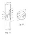
- FIG. 11is a schematic cross-sectional illustration of one embodiment of endoscope and ablator assembly according to the invention.
- FIG. 11Ais a more detailed schematic cross-sectional view of an endoscope according to the invention.
- FIG. 12is an end view, schematic illustration of the endoscope and ablator assembly shown in FIG. 11 ;
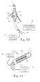
- FIG. 13is a schematic view of a contact heating ablation device employing the endoscope-guiding apparatus of the present invention.
- FIG. 14is a schematic view of a cryogenic ablation device employing the endoscope-guiding apparatus of the present invention.
- FIG. 15is a schematic view of a ultrasound heating ablation device employing the contacting sensing apparatus of the present invention.
- FIG. 16is a schematic illustration of a translation system for independently positioning the endoscope and ablation components of an endoscope/ablator assembly during a procedure.
- FIG. 1provides a schematic, cross-sectional view of a coaxial catheter ablation instrument 20 according to the invention, including an elongate body 14 and a projection balloon 26 inflatable via one or more ports 22 .
- the instrumentis preferably designed such that upon disposition within the heart (e.g., proximal to a pulmonary vein), the projection balloon can be inflated such that a shoulder portion 50 of the balloon 26 will be urged into close proximity with a target region 52 of cardiac tissue (e.g. an annular region of the atrial heart wall surrounding the ostium of a pulmonary vein).
- a target region 52 of cardiac tissuee.g. an annular region of the atrial heart wall surrounding the ostium of a pulmonary vein.
- the instrumentcan also include one or more ports 36 for delivering ablative fluid to the target region.
- the ablative fluidis preferably an energy transmissive medium, which helps deliver light, radiation or acoustic energy from a radiant energy source to a target tissue region.
- an ablative fluidis also useful to help conduct electrical current or heat to the target site.
- the ablative fluidalso serves to clear blood from the vicinity of the instrument and compensate for irregularities in the shape of the heart that might otherwise compromise the seating of the instrument. The ablative fluid thus provides a clear transmission pathway external to the balloon.
- a radiant energy emitter 40is shown disposed remotely from the target tissue (e.g., within a central lumen of the catheter body 14 or otherwise disposed within the balloon).
- the radiant energy sourceincludes at least one optical fiber coupled to a distal light projecting, optical element, which cooperate to project ablative light energy through the instrument to the target site.
- the catheter body, projection balloon and inflation/ablation fluidsare all preferably substantially transparent to the radiant energy at the selected wavelength to provide a low-loss transmission pathway from the ablation element 40 to the target.
- a reflectance sensorpreferably an endoscope 76 capable of capturing an image of the target site and/or the instrument position.
- the endoscopeis typically an optical fiber bundle with a lens or other optical coupler at its distal end to receive light.
- the reflectance sensor/endoscopecan also include an illumination source, such as an optical fiber coupled to a light source. Suitable endoscopes are available commercially from various sources including, for example, Myriad Fiber Imaging Tech, Inc. of Southbridge, Mass.
- the endoscopecan further include an optical head assembly, as detailed in more detail below, to increase the field of view.
- endoscopeas used herein is intended to encompass optical imaging devices, generally, including but not limited to endoscopes, fiberscopes, cardioscopes, angioscopes and other optical fiber-based imaging devices. More generally, “endoscope” encompasses any light-guiding (or waveguide) structure capable of transmitting an “image” of a object to a location for viewing.
- the viewing locationcan be direct, e.g., an eyepiece, or indirect, e.g., an image capture device, such as a CCD camera, which converts image data into a video display.
- FIG. 1Ais a schematic view of an endoscope/ablation element assembly 32 according to the invention including an ablation element 40 and an endoscope 76 .
- the assembly 32can be adapted for axial movement within an inner lumen of catheter body 14 .
- ablation element 40 and endoscope 76are adapted for independent axial movement within the assembly 32 .
- FIG. 2is a schematic illustration of an initial step in performing ablative surgery with radiant energy according to the invention, in which a guide wire 6 is introduced into a heart 2 and passed into a pulmonary vein 4 .
- FIG. 3Ais a schematic illustration of a method of performing ablative surgery with radiant energy according to the invention.
- catheter 20carrying projection balloon structure 26 , is slid over the guide wire 6 .
- This catheter 20can further include at least one internal fluid passageway (not shown) for inflation of the balloon 26 , which is sealed to the body of the catheter 20 by distal seal 21 and proximal seal 22 , such that the introduction of an inflation fluid into the balloon 26 can inflate the balloon.
- FIG. 3Billustrates how the projection balloon 26 can then be inflated to define a projection pathway for radiant energy ablation of cardiac tissue.
- the expanded projection balloondefines a staging through which radiant energy can be projected in accordance with the invention.
- the projection balloonis filled with a radiation-transmissive fluid so that radiant energy from an energy emitter can be efficiently passed through the instrument to a target region of cardiac tissue.
- the projection balloons described hereincan be preshaped to form parabolic like or various other shapes (e.g., to assist in seating the instrument at the mouth of a pulmonary vein or otherwise engaging the vein ostium or other anatomically defined regions of the heart). This can be accomplished, for example, by shaping and melting a TEFLON® film in a preshaped mold to effect the desired form.
- the projection balloons of the present inventioncan be made, for example, of thin wall polyethylene teraphthalate (PET) with a thickness of the membranes of about 5-50 micrometers.
- an ablative fluid 29can be employed outside of the instrument (e.g., between the balloon 26 and the target region 52 ) to ensure efficient transmission of the radiant energy when the instrument is deployed.
- the ablative fluid in this contextis any fluid that can serve as a conductor of the radiant energy.
- This ablative fluidcan be a physiologically compatible fluid, such as saline, or any other non-toxic aqueous fluid that is substantially transparent to the radiation. As shown in FIG.
- the fluid 29can be released via one or more exit ports 36 in the first catheter body 14 to flow between the projection balloon 26 and the surrounding tissue, thereby filling any gaps where the balloon 26 does not contact the tissue.
- the fluid 29can also serve an irrigation function by displacing any blood within the path of the radiant energy, which could otherwise interfere with the radiant light energy transmission to the target region 52 .
- FIG. 4is a schematic illustration of a further step in performing ablative surgery according to the invention, in which the guide wire is removed and replaced by a energy emitter 40 located remote from the desired lesion site 52 but in a position that permits projection of radiant energy onto a target region of the heart.
- the energy emittercan be introduced into the instrument via the lumen of the inner catheter.
- the energy emitter 40is a radiant energy emitter and includes at least one optical fiber 42 coupled to a distal light projecting, optical element 43 , which cooperate to project ablative light energy through the instrument to the target site.
- optical elementis a lens element capable of projecting an annular (ring-shaped) beam of radiation, as described in more detail in commonly owned U.S. Pat. No. 6,423,055 issued Jul. 22, 2002, herein incorporated by reference.
- the optical elementis adapted to project an arc-like pattern of radiation and the energy emitter can be rotated and/or translated to encircle the pulmonary vein.
- the radiant energy emittercan be an ultrasound or microwave energy source, as described in more detail below (in connection with FIGS. 9-10 ).
- FIGS. 4 and 5taken together, also illustrate an advantageous feature of the present invention, namely, the ability to select the location a lesion independent of the instrument design.
- the radiant energy emitterdoes not require contact with a target tissue region and is, in fact, decoupled from the rest of the instrument, the present invention permits the clinician to select a desired target region by simply moving the emitter (e.g., within the lumen of the catheter).
- the radiant energy emittercan be positioned to form a wide circumferential lesion (when the shape of the pulmonary vein ostium warrants such a lesion) by positioning the radiant energy emitter at the rear of the projection balloon—at a distance from the target tissue denoted as “C”.
- a smaller diameter lesioncan be formed by positioning the radiant energy emitter closer to the front of the project balloon, as shown in positions “A” or “B”. Smaller lesions can be preferably when the geometer of the vein ostium presents a sharper change in diameter, as shown by schematic wall segment 4 B. It should be appreciated that it may be desirable to change the intensity of the emitted radiation depending upon the distance it must be projected; thus a more intense radiant energy beam may be desirable in the scheme illustrated in position “C” in comparison with position “A.”.
- the energy emitter 40 and catheter body 14can each include one or more markers (shown schematically as elements 33 and 35 respectively) to aid in determining the location or tracking movements of the elements. Markers 33 and 35 , for example, can be radioopaque lines that can visualized fluoroscopically.
- the expandable elementcan include an orientation marker 57 which can be visualized endoscopically to visualize the position and/or orientations of the instrument.
- Each of the markers 33 , 35 and 57can be suitably shaped to provide three-dimensional information.
- the markerscan be shaped in the form of a “T” or an “L” (or, in the case of the circular, balloon neck marker 57 , with one or more azimuthal cross-marks) to assist in orientation.
- Various other marker mechanismssuch as magnetic, capacitive or optical markers, can also be used.
- the target sitee.g., the ostium of a pulmonary vein
- the target sitecan only be located by fluoroscopic inspection during injection of a contrast medium into the vein.
- Such imagesare transient.
- Location of the ablation catheter itself, even with radiopaque markersis likewise difficult because of the geometry of the heart.
- the heart's structureis largely invisible during fluoroscopic inspection.
- the endoscopic guidance systems of the present invention coupled with the use of orientation markerscan help overcome these problems.
- the use of radioopaque markers on the endoscope and/or the catheterallow the user to orient the ablation instrument relative to the pulmonary vein and permit anatomical features seen via the endoscope to be combined with fluoroscopic information.
- Orientation markers, such as elements 33 and 35can be used to determine the angular position of the instrument relative to structures such the ostia and also provide a measure of how far a movable element, such as the energy emitter 40 , has been advanced within the instrument. (It should be appreciated that numerous other marker schemes can be employed to achieve these objectives, including ring markers on either the energy emitter and/or the catheter body.)
- the ring marker shown as element 57 on the projection balloon 26can be replaced by a series of rings.
- physical markerscan be replaced with virtual markers generated electronically as part of the display. Such information is particularly useful in selection one or more of alternative sites for ablation.
- the inventioncan be used in conjunction with two or more fixed ablation elements (e.g., resistive heating bands of different circumferences) to select the most appropriate one (or set) of the ablation elements to be activated for lesion formation.
- the endoscopic guidance systems of the present inventioncan further be used to position any movable point source of ablative energy, e.g., a rotating contact or radiant ablation element in lieu of a slidably positionable source or together therewith, such that the desired path for circumferential can be visualized and followed by the ablation element.
- any movable point source of ablative energye.g., a rotating contact or radiant ablation element in lieu of a slidably positionable source or together therewith, such that the desired path for circumferential can be visualized and followed by the ablation element.
- the endoscopic guidance systems of the inventioncan be used together with various fluoroscopic or other imaging techniques to location and position anyone of the various instruments necessary for cardiac ablation.
- the ability to position the energy emitter, especially when radiant light is employed as the ablation modality,also permits endoscopic aiming of the energy.
- an aiming light beamcan be transmitted via the catheter to the target site such that the physician can visualize where the energy will be delivered.
- endoscopic guidancepermits the user to see where energy will be projected at various locations of the energy emitter.
- the instrumentis designed to project light in an annular ring around the ostium of a pulmonary vein, the aiming beam can be projected down the same optical delivery path as would the radiant energy.
- the “aiming ring”is projected onto a region of the atrium where a clear transmission pathway is seen (e.g., there is continuous contact (or the desired lesion path is otherwise cleared of blood), then the physician can begun the procedure. If, on the other hand, a clear transmission pathway is not seen at a particular location of the ablation element, then the ablation element can be moved until a clear lesion pathway is found.
- aimingcan be used advantageously with any radiant energy source and, in fact, it can also assist in the placement of fixed or contact based ablation elements.
- endoscope-guidancecan be combined with an aiming beam in any cardiac ablation system to improve positioning and predetermination of successful lesion formation.
- visualvisualize
- derivatives thereofare used herein to describe both human and machine uses of reflectance data.
- Such datacan take the form of images visible to a clinician's eye or any machine display of reflected light, e.g., in black & white, color or so-called “false color” or color enhanced views. Detection and display of reflected energy measurements outside the visible spectrum are also encompassed. In automated systems such visual data need not be displayed but rather employed direct by a controller to aid in the ablation procedure.
- FIG. 4-5further illustrates the unique utility of the multi-positionable, radiant energy ablation devices of the present invention in treating the complex cardiac geometries that are often encountered.
- the mouths of pulmonary veinstypically do not present simple, funnel-shaped, or regular conical surfaces. Instead, one side of the ostium 4 B can present a gentle sloping surface, while another side 4 A presents a sharper bend.
- contact-heating, ablation devicessuch geometries will result in incomplete lesions if the heating element (typically a resisting heating band on the surface of an expandable element) can not fully engage the tissue of the vein or ostium. Because the position of the heating band of the prior art devices is fixed, when it does not fully contact the target tissue, the result is an arc, or incompletely formed ring-type, lesion that typically will be insufficient to block conduction.
- the heating elementtypically a resisting heating band on the surface of an expandable element
- FIG. 4illustrates how the slidably positionable energy emitters of the present invention can be used to avoid this problem.
- Three potential positions of the emitter 40are shown in the figure (labeled as “A”, “B” and “C”). As shown, positions A and C may not result in optimal lesions because of gaps between the balloon and the target tissue. Position B, on the other hand, is preferably because circumferential contact has been achieved.
- Position Bis preferably because circumferential contact has been achieved.
- the independent positioning of the energy source relative to the balloonallows the clinician to “dial” an appropriately ring size to meet the encountered geometry.
- emittercan be positioned in many more positions and that the location can be varied in either discrete intervals or continuously, if so desired.
- the geometries of the pulmonary veinmay be such that no single annular lesion can form a continuous conduction block.
- the present inventionprovides a mechanism for addressing this problem by adjustment of the location of the energy emitter to form two or more partially circumferential lesions.
- the devices of the present inventioncan form a first lesion 94 and a second lesion 96 , each in the form of an arc or partial ring. Because each lesion has a thickness (dependent largely by the amount of energy deposited into the tissue) the two lesions can axially combine, as shown, to form a continuous encircling or circumscribing lesion that blocks conduction.
- FIG. 6is a schematic block diagram shown the endoscope/ablator assembly 32 comprising endoscope 76 and ablation element 40 connected to an analyzer system.
- the analyzer systemfurther includes a detector 34 for detecting reflected light (and preferable for generating a image).
- the output of the detector 34can be transmitted to a display 36 for clinician viewing.
- the display 36can be a simple eyepiece, a monitor or a heads-up projection onto glasses worn by members of the surgical team.
- the systemcan further include an energy source 39 , a controller 37 and a user interface 38 .
- the endoscope 76captures images which can be processed by the detector 34 and/or controller 37 to determine whether a suitable ablation path can be created.
- An aiming light source 31can also be used visualize the location where energy will be delivery to the tissue. If a suitable ablation path is seen by the surgeon, the controller 37 can transmit radiant energy from the ablation element 39 to a target tissue site to effect ablation.
- the controllercan further provide simulated displays to the user, superimposing, for example, a predicted lesion pattern on the image acquired by the detector or superimposing dosimetry information based on the lesion location.
- the controllercan further include a memory for storing and displaying data, such as pre-procedure images, lesion predictions and/or actual outcomes.
- the controllercan further provide a safety shutoff to the system in the event that a clear transmission pathway between the radiant energy source and the target tissue is lost during energy delivery.
- FIG. 7is a schematic illustration of one embodiment of a radiant energy emitter 40 A according to the invention.
- the radiant energyis electromagnetic radiation, e.g., coherent or laser light
- the energy emitter 40 Aprojects an hollow cone of radiation that forms an annular exposure pattern upon impingement with a target surface.
- radiant energy emitter 40 Acan include an optical fiber 42 in communication with an annulus-forming optical waveguide 44 having a concave interior boundary or surface 45 .
- the waveguide 44passes an annular beam of light to a graded intensity (GRIN) lens 46 , which serves to collimate the beam, keeping the beam width the same, over the projected distance.
- GRINgraded intensity
- the beam that exits from the distal window 48 of energy emitter 40will expand (in diameter) over distance, but the energy will remain largely confined to a narrow annular band.
- the angle of projection from the central axis of the optical fiber 42 or waveguide 44will be between about 20 and 60 degrees (for a total subtended angle of about 40 to about 120 degrees).
- the diameter of the annular beam of lightwill be dependent upon the distance from the point of projection to point of capture by a surface, e.g., a tissue site, e.g., an interstitial cavity or lumen.
- a surfacee.g., a tissue site, e.g., an interstitial cavity or lumen.
- the diameter of the annular beamwill be between about 10 mm and about 33 mm, preferably greater than 10 mm, greater than 15 mm, greater than 20 mm, and most preferably, greater than or equal to 23 mm.
- angle of projected annular lightis between about 20 and about 60 degrees, preferably between about 45 and about 55 degrees, most preferably in some applications about 50 degrees (total subtended angle 100 degrees).
- Preferred energy sources for use with the percutaneous ablation instruments of the present inventioninclude laser light in the range between about 200 nanometers and 2.5 micrometers.
- wavelengths that correspond to, or are near, water absorption peaksare often preferred.
- Such wavelengthsinclude those between about 805 nm and about 1060 nm, preferably between about 900 nm and 1000 nm, most preferably, between about 915 nm and 980 nm.
- wavelengths around 915 nm or around 980 nmare used during endocardial procedures.
- Suitable lasersinclude excimer lasers, gas lasers, solid state lasers and laser diodes.
- the optical waveguidescan be made from materials known in the art such as quartz, fused silica or polymers such as acrylics.
- acrylicsinclude acrylates, polyacrylic acid (PAA) and methacrylates, polymethacrylic acid (PMA).
- polyacrylic estersinclude polymethylacrylate (PMA), polyethylacrylate and polypropylacrylate.
- polymethacrylic estersinclude polymethylmethacrylate (PMMA), polyethylmethacrylate and polypropylmethacrylate.
- the waveguide 44is formed of quartz and fused to the end face of fiber 42 .
- Internal shaping of the waveguidecan be accomplished by removing a portion of material from a unitary body, e.g., a cylinder or rod.
- Methods known in the artcan be utilized to modify waveguide to have tapered inner walls, e.g., by grinding, milling, ablating, etc.
- a hollow polymeric cylindere.g., a tube
- the conical surface 45can be formed in a solid quartz cylinder or rod by drilling with a tapered bore.
- Waveguide 44can be optical coupled to optical fiber 42 by various methods known in the art. These methods include for example, gluing, or fusing with a torch or carbon dioxide laser.
- waveguide 44 , optical fiber 42 and, optionally, a gradient index lens (GRIN) 46are in communication and are held in position by heat shrinking a polymeric jacket material 49 , such as polyethylene terephthalate (PET) about the optical apparatus 40 .
- PETpolyethylene terephthalate
- FIG. 8is a schematic illustration of another embodiment of a radiant energy emitter 40 B according to the invention in which optical fiber 42 is coupled to a light diffuser 41 having light scattering particles 47 to produce a sidewise cylindrical exposure pattern of ablative radiation.
- This embodimentcan be useful, for example, in creating a lesion within a pulmonary vein.
- the radiant energy emitter of the design shown in FIG. 14can be advanced to the front of the projection balloon to permit diffuse exposure of a pulmonary vein ostium if a lesion is desired in that location.
- FIG. 9illustrates an alternative embodiment of a radiant energy emitter 40 C in which an ultrasound transducer 60 , comprising individual shaped transducer elements (and/or lenses or reflectors) 62 which direct (project) the ultrasound energy into a cone of energy that can likewise form an annular exposure pattern upon impingement with a target surface.
- the emitter 40 Cis supported by a sheath 66 or similar elongate body, enclosing electrical leads, and thereby permitting the clinician to advance the emitter through an inner lumen of the instrument to a desired position for ultrasound emission.
- FIG. 10Yet another embodiment of a radiant energy emitter 40 D is illustrated in FIG. 10 where microwave energy is similarly focused into an annular exposure beam.
- the radiant energy emittercan include a coaxial transmission line 74 (or similar electrical signal leads) and a helical coil antenna 73 .
- Radiation reflectors 72 A and 72 Bcooperated to shield and direct the radiation into a cone.
- a radioisotope or other source of ionizing radiationcan be used in lieu of the microwave antenna 73 , again with appropriate radiation shielding elements 72 A and 72 B to project a beam of ionizing radiation.
- FIGS. 11 and 12illustrate one embodiment of a contact sensor according to the invention incorporated into a radiant emitter assembly.
- the assemblycan includes an assembly body 32 that encases an endoscope/ablator assembly and facilitates slidable positioning within an inner lumen of catheter body 14 .
- the assemblyfurther includes an energy emitter 40 (e.g., like those described above in connection with FIGS. 7-10 ) which can also act as the sensing fiber.
- an ablation element 40is shown which can act as an illumination light source (when operated a low power). If the ablative element of the invention is properly positioned within the heart, light transmitted via such ablation element will strike the target region, be reflected back, and detected by the reflectance sensor 76 .
- the inventioncan be practiced with various numbers of illuminating and/or sensing elements, and with or without use of the energy emitter as an element in the contact sensing module.
- the emitter and the endoscopecan each move independently, if desired.
- ultrasound emitters and detectorscan also be used in the same manner in lieu of the light reflecting mechanisms to determine contact.
- the output signals of the sensorscan be electronically processed and incorporated into a display.
- the devices of the present inventioncan further include illumination elements that are capable of diffusing light to a large contact area of tissue by employing a scattering medium at the distal end of the illumination fiber.
- this diffusing materialcan be a matrix of titanium dioxide particles suspended in cured silicone. This diffusing medium allows high intensity light to be uniformly diffused over a large area preferably over an area greater than 40 mm in diameter.
- Endoscope 76can include an optical fiber bundle 78 for transmitting the captured image back to a detector and display, as well as a lenses 136 and 140 which provide an enhanced field of view.
- Such field enhancing elementspreferably increase the field of view to greater than 50 degrees, more preferably to about 70 degrees or higher.
- commercially available endoscopeshave a field of view of about 50 degrees or less in air.
- the field of view of the endoscopeis further reduced due to the refractive index difference between water and air. As explained in more detail below, a greater field of view is very important to endoscopic guidance.
- the endoscopes of FIGS. 11-12provide the ability to position the percutaneous ablation instruments of the present invention at a treatment site such that proper location of the energy emitter vis-a-vis the target tissue (as well a satisfactory degree of contact between the projection balloon and the tissue) is achieved.
- FIG. 11Aprovides a detailed schematic illustration of an endoscope 76 A with enhanced field of view.
- the endoscopecan include a fiber bundle 130 within a protective polyimide tube 132 coupled to distal stainless steel tube 134 in which the field-enhancing optics are disposed.
- an imaging lens 136 and an objective lens 140are situated, together with a centering and connecting tubes (e.g., tube 135 and 142 ) as may be needed to secure the lenses in place.
- a centering and connecting tubese.g., tube 135 and 142
- the endoscope 76 Ais designed to have a wide field of view even while it is immersed in liquid.
- the liquid in which it is immersedtypically can be either physiological saline in the inner lumen of the catheter or deuterium oxide which is one preferred medium for filling applicants' projection balloon. Both of these liquids have essentially the same index of refraction.
- a lens system shown FIG. 11Acan be used.
- the lens systemconsists of two plano-convex lenses 136 and 140 arranged as shown along with an aperture window 144 .
- High index of refraction materialsare preferably used for the lenses. Suitable materials include sapphire, cubic zirconia or high index glass materials. Alternatively, air-filled optical structures can be substituted for the solid lenses shown in the figure.
- the spherescan be made into hemispheres and the diameter of the hemispheres are reduced using common lens grinding technology.
- the aperturecan be constructed by metallizing one surface of flat glass plate. The central aperture hole is created by masking the flat glass before the metallization or removing the metallization with a laser.
- This lens systemhas field of view of slightly larger than 110° when immersed in water, an f number of about 2.5 and a depth of field that provides acceptable focus over a range of object distances from 13 mm to 40 mm.
- Acceptable focusis that degree of focus that results in minimum resolvable spot diameters that are close in size to 5 microns, which is the size of the individual fibers in the image bundle of the endoscope.
- the lens elementscan be assembled so the spherical surfaces touch and therefore the elements are self-locating when assembled in a small lens cell tube 138 with an inner diameter just slightly larger than the outer diameter of the lens elements.
- the lens cellis fabricated it is attached to the image bundle using techniques common to those skilled in the art.
- the general assemblycan use precise diameter tubes of polyimide whose dimensions can be controlled very precisely and whose wall thicknesses can be made very thin.
- the ability have a field of view greater that 50 degrees (and, preferably, in some applications, greater than 70 degrees, or 90 degrees)can be important because of the geometry of the heart and the ablation elements.
- Visualization the ostium of a pulmonary veininherently requires a wide field of view.
- the ablation element(including any expandable element) must be short because of the limited space available within the atrial chamber.
- the endoscopes of the present inventioncan also be used in conjunction with other optical reflectance measurements of light scattered or absorbed by blood, body fluids and tissue.
- white light projected by an illumination source toward tissuehas several components including red and green light.
- Red lighthas a wavelength range of about 600 to about 700 nanometers (nm) and green light has a wavelength range of about 500 to about 600 nm.
- red lighthas a wavelength range of about 600 to about 700 nanometers (nm)
- green lighthas a wavelength range of about 500 to about 600 nm.
- the optical assemblywhich includes a reflected light collector.
- the reflectance of green and blue lightincreases as biological tissue tends to reflect more green light.
- the amount of reflected green or blue lightdetermines whether there is blood between the apparatus and the tissue or not.
- the endoscopic displays of the present inventioncan incorporate filters (or generate “false-color” images) that emphasize the presence or absence of blood in the field. For example, when the inflated balloon member contacts the heart tissue (or is close enough that the balloon and ablative fluid released by the instrument form a clear transmission pathway), more green light will be reflected back into the optical assembly and the collector. The ratio of two or more different wavelengths can be used to enhance the image. Accordingly, a color-enhanced endoscope permit visualization of the instrument and/or the target site, as well as a determination of whether blood precludes the formation of a continuous lesion, e.g., circumferential lesion around the ostium of a pulmonary vein.
- filtersor generate “false-color” images
- spectrographic measurementscan be taken in tandem with endoscopic imaging,
- reflected lightcan be transmitted back through a collector, such as an optical fiber to a spectrophotometer.
- the spectrophotometer(Ocean Optics Spectrometer, Dunedin, Fla., model S-2000) produces a spectrum for each reflected pulse of reflected light.
- Commercially available software(LabView Software, Austin, Tex.) can isolate values for specific colors and perform ratio analyses.
- radiant energycan then be projected to the target tissue region.
- the radiant energyis electromagnetic radiation, e.g., laser radiation
- itcan be emitted onto the tissue site via a separate optical fiber or, alternatively, through the same optical fiber used to transmitting the white, green or red light.
- the laser lightcan be pulsed intermittently in synchronous fashion with the positioning/reflecting light to ensure that the pathway remains clear throughout the procedure.
- a contact-heating device 54 having an expandable element 56 and a contact heating element 58is shown disposed in a pulmonary vein.
- the contact heating elementcan be a line or grid of electrically conductive material printed on the surface of the expandable element.
- the expandable elementcan be substantially opaque to certain wavelengths (e.g., visible light) except for a transparent band 59 , on which the contact heating element is situated.
- the heating wiresshould also be sufficiently transparent (or cover a substantially small area of the band) so as to not interfere with reflection signal collection.
- the device 54can further include a sensor, e.g., an endoscope, disposed within a central lumen of the device having an illuminating fiber and a plurality of collecting fibers.
- FIG. 14another embodiment of a reflectance sensing or endoscope-guided catheter is shown in the form of a cryogenic ablation catheter 110 having a catheter body 112 and internal conduits 114 for circulation of a cryogenic fluid from a cryogenic fluid source 115 .
- the catheter bodycan include an expandable portion, e.g., a balloon structure, and further includes conductive regions 116 where the cold temperature can be applied to tissue.
- the endoscope 76 of the present inventioncan be disposed in proximity to the conductive regions, as shown and used to determine whether tissue contact has been made.
- FIG. 15yet another application for the contact sensors is shown in connection with an ultrasound, contact-heating balloon catheter 120 , having a balloon 122 (similar to that discussed above in connection with FIG. 13 ) for contacting a pulmonary vein ostium and having an optional band 123 for applying heat to tissue.
- the ultrasound ablation instrument 120further includes transducers 124 driven by actuator 125 to heat a desired region of tissue.
- the instrument 120can also included reflectors 126 to project the ultrasound energy through the balloon into an annular focus in the target tissue (or at the surface of the balloon).
- the reflectance or endoscopic sensors 76 of the present inventioncan be disposed within the balloon or catheter body, as shown, and used to determine whether tissue contact has been made.
- a translatory mechanism 80is shown for controlled movement of a radiant energy emitter within the instruments of the present invention.
- the exemplary positioner 80is incorporated into a handle 84 in the proximal region of the instrument, where the elongate body 82 of the radiant energy emitter 40 engages a thumb wheel 86 to control advancement and retraction of the emitter. It should be clear that various alternative mechanisms of manual or automated nature can be substituted for the illustrated thumb wheel 86 to position the emitter at a desired location relative to the target tissue region.
- the elongate body 82 that supports the radiant energy emitter 40can further include position indicia 92 on its surface to assist the clinician in placement of the ablation element within the instrument.
- the handlecan further include a window 90 whereby the user can read the indicia (e.g., gradation markers) to gauge how far the emitter has been advanced into the instrument.
- the assembly 32can further include an endoscope translatory mechanism 98 as shown in FIG. 16 for controlled movement of the reflectance sensor or endoscope 76 within the instruments of the present invention.
- the exemplary positioner 98can be incorporated into a handle 99 in the proximal region of the instrument, where the elongate body of the sensor 76 engages a thumb wheel 97 to control advancement and retraction of the emitter.
- the apparatus of the present inventionthus permits the selection of an ablative lesion, e.g., a circumferential lesion, of desired shape and size.
- This adjustabilitycan be used advantageously to form a lesion at a desired location, or along a desired path, to effectively block conduction and thereby treat atrial fibrillation.
- radiatant energyas used herein is intended to encompass energy sources that do not rely primarily on conductive or convective heat transfer. Such sources include, but are not limited to, acoustic and electromagnetic radiation sources and, more specifically, include microwave, x-ray, gamma-ray, ultrasonic and radiant light sources.
- the term “light” as used hereinis intended to encompass electromagnetic radiation including, but not limited to, visible light, infrared and ultraviolet radiation.
- a lesionin the context of a lesion is intended to mean a lesion that substantially blocks electrical conduction between tissue segments on opposite sides of the lesion.
- the terms “circumferential” and/or “curvilinear,” including derivatives thereof,are herein intended to mean a path or line which forms an outer border or perimeter that either partially or completely surrounds a region of tissue, or separate one region of tissue from another.
- a “circumferential” path or elementmay include one or more of several shapes, and may be for example, circular, annular, oblong, ovular, elliptical, semi annular, or toroidal.
- Lumenin the context of biological structures, is herein intended to mean any cavity or lumen within the body which is defined at least in part by a tissue wall.
- tissue wallFor example, cardiac chambers, the uterus, the regions of the gastrointestinal tract, the urinary tract, and the arterial or venous vessels are all considered illustrative examples of body spaces within the intended meaning.
- Catheteras used herein is intended to encompass any hollow instrument capable of penetrating body tissue or interstitial cavities and providing a conduit for selectively injecting a solution or gas, including without limitation, venous and arterial conduits of various sizes and shapes, bronchoscopes, endoscopes, cystoscopes, culpascopes, colonscopes, trocars, laparoscopes and the like.
- Catheters of the present inventioncan be constructed with biocompatible materials known to those skilled in the art such as those listed supra, e.g., silastic, polyethylene, Teflon, polyurethanes, etc.
- catheterincluding derivatives thereof, in the context of catheters is intended to encompass any passageway within a catheter instrument (and/or track otherwise joined to such instrument that can serve as a passageway) for the passage of other component instruments or fluids or for delivery of therapeutic agents or for sampling or otherwise detecting a condition at a remote region of the instrument.
- catheteris also intended to encompass any elongate body capable of serving as a conduit for one or more of the ablation, expandable or sensing elements described herein, e.g., energy emitters, balloons and/or endoscopes.
- the term “catheter”can encompass either the outer catheter body or sheath or other instruments that can be introduced through such a sheath.
- the use of the term “catheter”should not be construed as meaning only a single instrument but rather is used to encompass both singular and plural instruments, including 30 coaxial, nested and other tandem arrangements.
- veinor “blood vessel” includes, without limitation, veins, arteries, and various chambers or regions of the heart, such as the atria, ventricles, coronary sinus, vena cava and, in particular, the ostia or antrum of the pulmonary veins.
- balloonencompasses deformable hollow shapes which can be inflated into various configurations including balloon, circular, tear drop, etc., shapes dependent upon the requirements of the body cavity.
- balloon elementscan be elastic or simply capable of unfolding or unwrapping into an expanded state.
- the ballooncan further encompass multiple chamber configurations.
- transparentis well recognized in the art and is intended to include those materials which allow transmission of energy through, for example, the primary balloon member. Preferred transparent materials do not significantly impede (e.g., result in losses of over 20 percent of energy transmitted) the energy being transferred from an energy emitter to the tissue or cell site. Suitable transparent materials include fluoropolymers, for example, fluorinated ethylene propylene (FEP), perfluoroalkoxy resin (PFA), polytetrafluoroethylene (PTFE), and ethylene-tetrafluoroethylene (ETFE) or polyester resins including polyethylene teraphathalate (PET).
- FEPfluorinated ethylene propylene
- PFAperfluoroalkoxy resin
- PTFEpolytetrafluoroethylene
- ETFEethylene-tetrafluoroethylene
Landscapes
- Health & Medical Sciences (AREA)
- Life Sciences & Earth Sciences (AREA)
- Surgery (AREA)
- Engineering & Computer Science (AREA)
- Physics & Mathematics (AREA)
- Animal Behavior & Ethology (AREA)
- Veterinary Medicine (AREA)
- Public Health (AREA)
- Nuclear Medicine, Radiotherapy & Molecular Imaging (AREA)
- General Health & Medical Sciences (AREA)
- Biomedical Technology (AREA)
- Heart & Thoracic Surgery (AREA)
- Molecular Biology (AREA)
- Medical Informatics (AREA)
- Optics & Photonics (AREA)
- Radiology & Medical Imaging (AREA)
- Otolaryngology (AREA)
- Biophysics (AREA)
- Pathology (AREA)
- Electromagnetism (AREA)
- Plasma & Fusion (AREA)
- Cardiology (AREA)
- Surgical Instruments (AREA)
Abstract
Description
| TABLE 1 |
| Lens Specifications |
| Spherical | Overall | Center | ||
| Element Name | Material | Radius | Diameter | thickness |
| Object Lens | Cubic Zirconia | 0.200 mm | 0.400 mm | 0.244 mm |
| or high index | ||||
| glass | ||||
| Image Lens | Saphire or high | 0.300 mm | 0.400 mm | 0.187 mm |
| index glass | ||||
| Aperture | Schott B270 | Flat on both | 0.400 mm | 0.125 mm |
| Window 0.060 | Grade A glass | Faces | ||
| mm dia. | ||||
Claims (18)
Priority Applications (1)
| Application Number | Priority Date | Filing Date | Title |
|---|---|---|---|
| US15/380,637US9861437B2 (en) | 1999-07-14 | 2016-12-15 | Guided cardiac ablation catheters |
Applications Claiming Priority (11)
| Application Number | Priority Date | Filing Date | Title |
|---|---|---|---|
| US09/357,355US6423055B1 (en) | 1999-07-14 | 1999-07-14 | Phototherapeutic wave guide apparatus |
| US09/602,420US6572609B1 (en) | 1999-07-14 | 2000-06-23 | Phototherapeutic waveguide apparatus |
| US09/616,275US6626900B1 (en) | 1999-07-14 | 2000-07-14 | Intralumenal contact sensor |
| US09/924,393US6676656B2 (en) | 1994-09-09 | 2001-08-07 | Surgical ablation with radiant energy |
| US31715603A | 2003-02-03 | 2003-02-03 | |
| US10/357,156US8025661B2 (en) | 1994-09-09 | 2003-02-03 | Coaxial catheter instruments for ablation with radiant energy |
| US47737403P | 2003-06-10 | 2003-06-10 | |
| US10/674,114US6942657B2 (en) | 1999-07-14 | 2003-09-29 | Intralumenal contact sensor |
| US10/865,558US8540704B2 (en) | 1999-07-14 | 2004-06-10 | Guided cardiac ablation catheters |
| US13/952,013US20140031802A1 (en) | 1999-07-14 | 2013-07-26 | Guided cardiac ablation catheters |
| US15/380,637US9861437B2 (en) | 1999-07-14 | 2016-12-15 | Guided cardiac ablation catheters |
Related Parent Applications (1)
| Application Number | Title | Priority Date | Filing Date |
|---|---|---|---|
| US13/952,013ContinuationUS20140031802A1 (en) | 1999-07-14 | 2013-07-26 | Guided cardiac ablation catheters |
Publications (2)
| Publication Number | Publication Date |
|---|---|
| US20170156793A1 US20170156793A1 (en) | 2017-06-08 |
| US9861437B2true US9861437B2 (en) | 2018-01-09 |
Family
ID=34317837
Family Applications (3)
| Application Number | Title | Priority Date | Filing Date |
|---|---|---|---|
| US10/865,558Expired - LifetimeUS8540704B2 (en) | 1999-07-14 | 2004-06-10 | Guided cardiac ablation catheters |
| US13/952,013AbandonedUS20140031802A1 (en) | 1999-07-14 | 2013-07-26 | Guided cardiac ablation catheters |
| US15/380,637Expired - Fee RelatedUS9861437B2 (en) | 1999-07-14 | 2016-12-15 | Guided cardiac ablation catheters |
Family Applications Before (2)
| Application Number | Title | Priority Date | Filing Date |
|---|---|---|---|
| US10/865,558Expired - LifetimeUS8540704B2 (en) | 1999-07-14 | 2004-06-10 | Guided cardiac ablation catheters |
| US13/952,013AbandonedUS20140031802A1 (en) | 1999-07-14 | 2013-07-26 | Guided cardiac ablation catheters |
Country Status (1)
| Country | Link |
|---|---|
| US (3) | US8540704B2 (en) |
Cited By (3)
| Publication number | Priority date | Publication date | Assignee | Title |
|---|---|---|---|---|
| WO2020224972A1 (en) | 2019-05-07 | 2020-11-12 | Vascomed Gmbh | Mapping and ablation catheter with multiple loop segments |
| US11925333B2 (en) | 2019-02-01 | 2024-03-12 | Covidien Lp | System for fluoroscopic tracking of a catheter to update the relative position of a target and the catheter in a 3D model of a luminal network |
| US12306426B2 (en) | 2021-08-27 | 2025-05-20 | Furukawa Electric Co., Ltd. | Radiation probe with radial scatter regions with various intensities |
Families Citing this family (143)
| Publication number | Priority date | Publication date | Assignee | Title |
|---|---|---|---|---|
| US8025661B2 (en)* | 1994-09-09 | 2011-09-27 | Cardiofocus, Inc. | Coaxial catheter instruments for ablation with radiant energy |
| US7935108B2 (en) | 1999-07-14 | 2011-05-03 | Cardiofocus, Inc. | Deflectable sheath catheters |
| US8900219B2 (en)* | 1999-07-14 | 2014-12-02 | Cardiofocus, Inc. | System and method for visualizing tissue during ablation procedures |
| US8540704B2 (en) | 1999-07-14 | 2013-09-24 | Cardiofocus, Inc. | Guided cardiac ablation catheters |
| US9033961B2 (en)* | 1999-07-14 | 2015-05-19 | Cardiofocus, Inc. | Cardiac ablation catheters for forming overlapping lesions |
| US8614768B2 (en)* | 2002-03-18 | 2013-12-24 | Raytheon Company | Miniaturized imaging device including GRIN lens optically coupled to SSID |
| US10610406B2 (en)* | 2004-07-21 | 2020-04-07 | Vanderbilt University | Drug delivery device and applications of same |
| US9510732B2 (en) | 2005-10-25 | 2016-12-06 | Intuitive Surgical Operations, Inc. | Methods and apparatus for efficient purging |
| US11478152B2 (en) | 2005-02-02 | 2022-10-25 | Intuitive Surgical Operations, Inc. | Electrophysiology mapping and visualization system |
| US7930016B1 (en) | 2005-02-02 | 2011-04-19 | Voyage Medical, Inc. | Tissue closure system |
| US8078266B2 (en) | 2005-10-25 | 2011-12-13 | Voyage Medical, Inc. | Flow reduction hood systems |
| US10064540B2 (en) | 2005-02-02 | 2018-09-04 | Intuitive Surgical Operations, Inc. | Visualization apparatus for transseptal access |
| US7860555B2 (en) | 2005-02-02 | 2010-12-28 | Voyage Medical, Inc. | Tissue visualization and manipulation system |
| US8137333B2 (en) | 2005-10-25 | 2012-03-20 | Voyage Medical, Inc. | Delivery of biological compounds to ischemic and/or infarcted tissue |
| US7918787B2 (en)* | 2005-02-02 | 2011-04-05 | Voyage Medical, Inc. | Tissue visualization and manipulation systems |
| US7860556B2 (en)* | 2005-02-02 | 2010-12-28 | Voyage Medical, Inc. | Tissue imaging and extraction systems |
| US8050746B2 (en) | 2005-02-02 | 2011-11-01 | Voyage Medical, Inc. | Tissue visualization device and method variations |
| US20080015569A1 (en) | 2005-02-02 | 2008-01-17 | Voyage Medical, Inc. | Methods and apparatus for treatment of atrial fibrillation |
| US8221310B2 (en) | 2005-10-25 | 2012-07-17 | Voyage Medical, Inc. | Tissue visualization device and method variations |
| US7749249B2 (en) | 2006-02-21 | 2010-07-06 | Kardium Inc. | Method and device for closing holes in tissue |
| US8628520B2 (en)* | 2006-05-02 | 2014-01-14 | Biosense Webster, Inc. | Catheter with omni-directional optical lesion evaluation |
| US8038598B2 (en)* | 2006-05-15 | 2011-10-18 | Baystate Health, Inc. | Balloon endoscope device |
| US20070270688A1 (en) | 2006-05-19 | 2007-11-22 | Daniel Gelbart | Automatic atherectomy system |
| US9055906B2 (en) | 2006-06-14 | 2015-06-16 | Intuitive Surgical Operations, Inc. | In-vivo visualization systems |
| US9119633B2 (en) | 2006-06-28 | 2015-09-01 | Kardium Inc. | Apparatus and method for intra-cardiac mapping and ablation |
| US8920411B2 (en) | 2006-06-28 | 2014-12-30 | Kardium Inc. | Apparatus and method for intra-cardiac mapping and ablation |
| US10028783B2 (en) | 2006-06-28 | 2018-07-24 | Kardium Inc. | Apparatus and method for intra-cardiac mapping and ablation |
| US8449605B2 (en) | 2006-06-28 | 2013-05-28 | Kardium Inc. | Method for anchoring a mitral valve |
| US11389232B2 (en) | 2006-06-28 | 2022-07-19 | Kardium Inc. | Apparatus and method for intra-cardiac mapping and ablation |
| US20080004478A1 (en)* | 2006-07-03 | 2008-01-03 | Darius Francescatti | Endoscopic/percutaneous electronic radiation applicator and delivery system |
| US7837610B2 (en) | 2006-08-02 | 2010-11-23 | Kardium Inc. | System for improving diastolic dysfunction |
| WO2008028149A2 (en) | 2006-09-01 | 2008-03-06 | Voyage Medical, Inc. | Electrophysiology mapping and visualization system |
| US10004388B2 (en) | 2006-09-01 | 2018-06-26 | Intuitive Surgical Operations, Inc. | Coronary sinus cannulation |
| US20080097476A1 (en) | 2006-09-01 | 2008-04-24 | Voyage Medical, Inc. | Precision control systems for tissue visualization and manipulation assemblies |
| US8728073B2 (en)* | 2006-10-10 | 2014-05-20 | Biosense Webster, Inc. | Multi-region staged inflation balloon |
| US10335131B2 (en) | 2006-10-23 | 2019-07-02 | Intuitive Surgical Operations, Inc. | Methods for preventing tissue migration |
| US8986298B2 (en) | 2006-11-17 | 2015-03-24 | Biosense Webster, Inc. | Catheter with omni-directional optical tip having isolated optical paths |
| TW200824643A (en)* | 2006-12-13 | 2008-06-16 | Chieh-Hsiao Chen | Guiding stylet apparatus |
| US20080183036A1 (en) | 2006-12-18 | 2008-07-31 | Voyage Medical, Inc. | Systems and methods for unobstructed visualization and ablation |
| US8131350B2 (en) | 2006-12-21 | 2012-03-06 | Voyage Medical, Inc. | Stabilization of visualization catheters |
| US9226648B2 (en)* | 2006-12-21 | 2016-01-05 | Intuitive Surgical Operations, Inc. | Off-axis visualization systems |
| US20080234572A1 (en)* | 2007-03-23 | 2008-09-25 | Civco Medical Instruments Co., Inc. | Fiducial marker with absorbable connecting sleeve and absorbable spacer for imaging localization |
| EP2148608A4 (en) | 2007-04-27 | 2010-04-28 | Voyage Medical Inc | Complex shape steerable tissue visualization and manipulation catheter |
| US8657805B2 (en) | 2007-05-08 | 2014-02-25 | Intuitive Surgical Operations, Inc. | Complex shape steerable tissue visualization and manipulation catheter |
| WO2008141238A1 (en) | 2007-05-11 | 2008-11-20 | Voyage Medical, Inc. | Visual electrode ablation systems |
| US7835074B2 (en) | 2007-06-05 | 2010-11-16 | Sterling Lc | Mini-scope for multi-directional imaging |
| US20090030276A1 (en)* | 2007-07-27 | 2009-01-29 | Voyage Medical, Inc. | Tissue visualization catheter with imaging systems integration |
| US20090062790A1 (en)* | 2007-08-31 | 2009-03-05 | Voyage Medical, Inc. | Direct visualization bipolar ablation systems |
| US8235985B2 (en) | 2007-08-31 | 2012-08-07 | Voyage Medical, Inc. | Visualization and ablation system variations |
| US8906011B2 (en) | 2007-11-16 | 2014-12-09 | Kardium Inc. | Medical device for use in bodily lumens, for example an atrium |
| US8500730B2 (en)* | 2007-11-16 | 2013-08-06 | Biosense Webster, Inc. | Catheter with omni-directional optical tip having isolated optical paths |
| US9717501B2 (en)* | 2007-11-21 | 2017-08-01 | St. Jude Medical, Atrial Fibrillation Division, Inc. | Methods and systems for occluding vessels during cardiac ablation including optional electroanatomical guidance |
| US8217523B2 (en)* | 2007-12-07 | 2012-07-10 | Veryst Engineering Llc | Apparatus for in vivo energy harvesting |
| US8489172B2 (en)* | 2008-01-25 | 2013-07-16 | Kardium Inc. | Liposuction system |
| US8858609B2 (en) | 2008-02-07 | 2014-10-14 | Intuitive Surgical Operations, Inc. | Stent delivery under direct visualization |
| US20090287304A1 (en) | 2008-05-13 | 2009-11-19 | Kardium Inc. | Medical Device for Constricting Tissue or a Bodily Orifice, for example a mitral valve |
| US20090287048A1 (en)* | 2008-05-16 | 2009-11-19 | Sterling Lc | Method and apparatus for imaging within a living body |
| WO2009155441A2 (en)* | 2008-06-18 | 2009-12-23 | Sterling Lc | Transparent endoscope head defining a focal length |
| US20090326321A1 (en)* | 2008-06-18 | 2009-12-31 | Jacobsen Stephen C | Miniaturized Imaging Device Including Multiple GRIN Lenses Optically Coupled to Multiple SSIDs |
| US9101735B2 (en) | 2008-07-07 | 2015-08-11 | Intuitive Surgical Operations, Inc. | Catheter control systems |
| WO2010014792A2 (en) | 2008-07-30 | 2010-02-04 | Sterling Lc | Method and device for incremental wavelength variation to analyze tissue |
| EP2163218A1 (en)* | 2008-09-16 | 2010-03-17 | Osyris Medical | Device for treating part of a human or animal body comprising an instrument for dispensing and/or an instrument for locally sucking up treatment doses and means for controlling dosimetry |
| US8894643B2 (en) | 2008-10-10 | 2014-11-25 | Intuitive Surgical Operations, Inc. | Integral electrode placement and connection systems |
| US8333012B2 (en) | 2008-10-10 | 2012-12-18 | Voyage Medical, Inc. | Method of forming electrode placement and connection systems |
| WO2010053916A2 (en) | 2008-11-04 | 2010-05-14 | Sterling Lc | Method and device for wavelength shifted imaging |
| US9795442B2 (en) | 2008-11-11 | 2017-10-24 | Shifamed Holdings, Llc | Ablation catheters |
| US9468364B2 (en) | 2008-11-14 | 2016-10-18 | Intuitive Surgical Operations, Inc. | Intravascular catheter with hood and image processing systems |
| WO2011041720A2 (en) | 2009-10-01 | 2011-04-07 | Jacobsen Stephen C | Method and apparatus for manipulating movement of a micro-catheter |
| WO2011041728A2 (en) | 2009-10-01 | 2011-04-07 | Jacobsen Stephen C | Needle delivered imaging device |
| WO2011041730A2 (en)* | 2009-10-01 | 2011-04-07 | Jacobsen Stephen C | Light diffusion apparatus |
| WO2011041571A2 (en) | 2009-10-01 | 2011-04-07 | Kardium Inc. | Medical device, kit and method for constricting tissue or a bodily orifice, for example, a mitral valve |
| US20110082450A1 (en)* | 2009-10-02 | 2011-04-07 | Cardiofocus, Inc. | Cardiac ablation system with inflatable member having multiple inflation settings |
| US8696653B2 (en)* | 2009-10-02 | 2014-04-15 | Cardiofocus, Inc. | Cardiac ablation system with pulsed aiming light |
| WO2011041638A2 (en)* | 2009-10-02 | 2011-04-07 | Cardiofocus, Inc. | Cardiac ablation system with automatic safety shut-off feature |
| US8702688B2 (en)* | 2009-10-06 | 2014-04-22 | Cardiofocus, Inc. | Cardiac ablation image analysis system and process |
| US8828028B2 (en) | 2009-11-03 | 2014-09-09 | Raytheon Company | Suture device and method for closing a planar opening |
| US8694071B2 (en) | 2010-02-12 | 2014-04-08 | Intuitive Surgical Operations, Inc. | Image stabilization techniques and methods |
| JP5608871B2 (en)* | 2010-03-09 | 2014-10-15 | 学校法人慶應義塾 | System for preventing blood burn at the laser catheter emitting part |
| US9814522B2 (en) | 2010-04-06 | 2017-11-14 | Intuitive Surgical Operations, Inc. | Apparatus and methods for ablation efficacy |
| AU2011252976A1 (en) | 2010-05-12 | 2012-11-08 | Shifamed Holdings, Llc | Low profile electrode assembly |
| US9655677B2 (en) | 2010-05-12 | 2017-05-23 | Shifamed Holdings, Llc | Ablation catheters including a balloon and electrodes |
| US8940002B2 (en) | 2010-09-30 | 2015-01-27 | Kardium Inc. | Tissue anchor system |
| JP2012147937A (en)* | 2011-01-19 | 2012-08-09 | Sony Corp | Laser therapy apparatus, laser therapy system and assessment method |
| US9452016B2 (en) | 2011-01-21 | 2016-09-27 | Kardium Inc. | Catheter system |
| CA2764494A1 (en) | 2011-01-21 | 2012-07-21 | Kardium Inc. | Enhanced medical device for use in bodily cavities, for example an atrium |
| US11259867B2 (en) | 2011-01-21 | 2022-03-01 | Kardium Inc. | High-density electrode-based medical device system |
| US9480525B2 (en) | 2011-01-21 | 2016-11-01 | Kardium, Inc. | High-density electrode-based medical device system |
| US9943360B2 (en) | 2011-01-30 | 2018-04-17 | University Health Network | Coil electrode for thermal therapy |
| US9072511B2 (en) | 2011-03-25 | 2015-07-07 | Kardium Inc. | Medical kit for constricting tissue or a bodily orifice, for example, a mitral valve |
| US9014789B2 (en) | 2011-09-22 | 2015-04-21 | The George Washington University | Systems and methods for visualizing ablated tissue |
| AU2012312066C1 (en) | 2011-09-22 | 2016-06-16 | 460Medical, Inc. | Systems and methods for visualizing ablated tissue |
| USD777925S1 (en) | 2012-01-20 | 2017-01-31 | Kardium Inc. | Intra-cardiac procedure device |
| USD777926S1 (en) | 2012-01-20 | 2017-01-31 | Kardium Inc. | Intra-cardiac procedure device |
| US9198592B2 (en) | 2012-05-21 | 2015-12-01 | Kardium Inc. | Systems and methods for activating transducers |
| US10827977B2 (en) | 2012-05-21 | 2020-11-10 | Kardium Inc. | Systems and methods for activating transducers |
| US9017321B2 (en) | 2012-05-21 | 2015-04-28 | Kardium, Inc. | Systems and methods for activating transducers |
| US9770296B2 (en)* | 2012-07-31 | 2017-09-26 | Katalyst Surgical, Llc | Steerable laser probe |
| US9877867B2 (en)* | 2012-08-01 | 2018-01-30 | Katalyst Surgical, Llc | Steerable laser probe |
| US9226855B2 (en)* | 2012-09-06 | 2016-01-05 | Katalyst Surgical, Llc | Steerable laser probe |
| WO2014138410A1 (en)* | 2013-03-08 | 2014-09-12 | Symple Surgical Inc. | Balloon catheter apparatus with microwave emitter |
| US10076384B2 (en) | 2013-03-08 | 2018-09-18 | Symple Surgical, Inc. | Balloon catheter apparatus with microwave emitter |
| WO2014165130A2 (en)* | 2013-03-13 | 2014-10-09 | Boston Scientific Scimed, Inc. | Devices for tissue separation and related methods of use |
| WO2014146126A1 (en) | 2013-03-15 | 2014-09-18 | Myoscience, Inc. | Cryogenic blunt dissection methods and devices |
| US9295512B2 (en) | 2013-03-15 | 2016-03-29 | Myoscience, Inc. | Methods and devices for pain management |
| US9610112B2 (en) | 2013-03-15 | 2017-04-04 | Myoscience, Inc. | Cryogenic enhancement of joint function, alleviation of joint stiffness and/or alleviation of pain associated with osteoarthritis |
| US10098694B2 (en) | 2013-04-08 | 2018-10-16 | Apama Medical, Inc. | Tissue ablation and monitoring thereof |
| KR20150140760A (en)* | 2013-04-08 | 2015-12-16 | 아파마 메디칼, 인크. | Cardiac ablation catheters and methods of use thereof |
| US10349824B2 (en) | 2013-04-08 | 2019-07-16 | Apama Medical, Inc. | Tissue mapping and visualization systems |
| JP6737705B2 (en) | 2013-11-14 | 2020-08-12 | ザ・ジョージ・ワシントン・ユニバーシティThe George Washingtonuniversity | Method of operating system for determining depth of injury site and system for generating images of heart tissue |
| JP2017500550A (en) | 2013-11-20 | 2017-01-05 | ザ・ジョージ・ワシントン・ユニバーシティThe George Washingtonuniversity | System and method for hyperspectral analysis of cardiac tissue |
| EP3137007A4 (en)* | 2014-04-28 | 2017-09-27 | Cardiofocus, Inc. | System and method for visualizing tissue with an icg dye composition during ablation procedures |
| KR102499045B1 (en) | 2014-11-03 | 2023-02-10 | 더 조지 워싱턴 유니버시티 | Systems and methods for lesion assessment |
| EP3215001A4 (en) | 2014-11-03 | 2018-04-04 | Luxcath, LLC | Systems and methods for assessment of contact quality |
| US10722184B2 (en) | 2014-11-17 | 2020-07-28 | Kardium Inc. | Systems and methods for selecting, activating, or selecting and activating transducers |
| US10368936B2 (en) | 2014-11-17 | 2019-08-06 | Kardium Inc. | Systems and methods for selecting, activating, or selecting and activating transducers |
| EP3223735A4 (en)* | 2014-11-25 | 2018-07-11 | Luxcath, LLC | Visualization catheters |
| US10154888B2 (en) | 2014-12-03 | 2018-12-18 | Cardiofocus, Inc. | System and method for visual confirmation of pulmonary vein isolation during abalation procedures |
| EP3269180B1 (en)* | 2015-03-12 | 2020-11-25 | Honeywell International Inc. | Wireless mesh network gas detection real time location system and method |
| US10156552B2 (en) | 2015-05-13 | 2018-12-18 | Honeywell International Inc. | Method to auto-configure gas detectors based on real-time location |
| WO2016210437A1 (en)* | 2015-06-26 | 2016-12-29 | Apama Medical, Inc. | Tissue mapping and visualization systems |
| US10779904B2 (en) | 2015-07-19 | 2020-09-22 | 460Medical, Inc. | Systems and methods for lesion formation and assessment |
| US11154186B2 (en) | 2015-07-31 | 2021-10-26 | University Of Utah Research Foundation | Devices, systems, and methods for imaging and treating a selected tissue |
| EP4302713A3 (en) | 2015-11-16 | 2024-03-13 | Boston Scientific Scimed, Inc. | Energy delivery devices |
| EP3368156B1 (en)* | 2015-12-10 | 2020-02-12 | St. Jude Medical, Cardiology Division, Inc. | Blood vessel isolation ablation device |
| US11344365B2 (en) | 2016-01-05 | 2022-05-31 | Cardiofocus, Inc. | Ablation system with automated sweeping ablation energy element |
| US10702163B2 (en) | 2016-05-03 | 2020-07-07 | Precision EP GmbH | Systems and methods for intracavitary temperature measurement and monitoring |
| WO2018109109A1 (en) | 2016-12-16 | 2018-06-21 | Sony Corporation | An optical scope system for capturing an image of a scene |
| WO2018128644A1 (en)* | 2017-01-09 | 2018-07-12 | Scott Koss | Trans-ventricular introducer sheath with intracardiac/extracardiac stabilization and a suture retention system |
| US11602270B2 (en) | 2017-02-01 | 2023-03-14 | University Of Utah Research Foundation | Devices and methods for mapping cardiac tissue |
| USD851245S1 (en) | 2017-04-14 | 2019-06-11 | Cardiofocus, Inc. | Compliant balloon |
| EP3740147B1 (en) | 2018-01-15 | 2024-03-27 | Cardiofocus, Inc. | Ablation system with automated ablation energy element |
| US20210212571A1 (en)* | 2018-05-16 | 2021-07-15 | Ji-Xin Cheng | Intravascular photoacoustic tomography apparatus and method thereof |
| WO2020071023A1 (en)* | 2018-10-01 | 2020-04-09 | 株式会社カネカ | Light irradiating medical device |
| US11877065B2 (en)* | 2019-06-20 | 2024-01-16 | Cilag Gmbh International | Image rotation in an endoscopic hyperspectral imaging system |
| US11172811B2 (en) | 2019-06-20 | 2021-11-16 | Cilag Gmbh International | Image rotation in an endoscopic fluorescence imaging system |
| US11134832B2 (en) | 2019-06-20 | 2021-10-05 | Cilag Gmbh International | Image rotation in an endoscopic hyperspectral, fluorescence, and laser mapping imaging system |
| US11671691B2 (en) | 2019-06-20 | 2023-06-06 | Cilag Gmbh International | Image rotation in an endoscopic laser mapping imaging system |
| JP2022543429A (en)* | 2019-08-05 | 2022-10-12 | ジャイラス エーシーエムアイ インク ディー/ビー/エー オリンパス サージカル テクノロジーズ アメリカ | fiber optic assembly |
| CN114981695B (en) | 2019-12-17 | 2024-11-12 | 犹他大学研究基金会 | Characterizing Cardiac Tissue Using Catheterized Light Scattering Spectroscopy |
| EP4087511A4 (en) | 2020-01-08 | 2024-02-14 | 460Medical, Inc. | Systems and methods for optical interrogation of ablation lesions |
| US11849995B2 (en) | 2021-02-18 | 2023-12-26 | Biosense Webster (Israel) Ltd. | Detection of balloon catheter tissue contact using optical measurement |
| CN115500936B (en)* | 2022-10-24 | 2025-08-19 | 南京诺源医疗器械有限公司 | Microwave ablation system and method |
| TWI851106B (en)* | 2023-03-23 | 2024-08-01 | 晶鑠科技有限公司 | Thermal imaging endoscope system, endoscope catheter, detecting method for abnormal regions, device for displaying abnormal regions, and thermal imaging processing host thereof |
Citations (229)
| Publication number | Priority date | Publication date | Assignee | Title |
|---|---|---|---|---|
| US3417745A (en) | 1963-08-23 | 1968-12-24 | Sheldon Edward Emanuel | Fiber endoscope provided with focusing means and electroluminescent means |
| US3821510A (en) | 1973-02-22 | 1974-06-28 | H Muncheryan | Hand held laser instrumentation device |
| US4224929A (en) | 1977-11-08 | 1980-09-30 | Olympus Optical Co., Ltd. | Endoscope with expansible cuff member and operation section |
| US4233493A (en) | 1974-05-21 | 1980-11-11 | Nath Guenther | Apparatus for applying intense light radiation to a limited area |
| US4273109A (en) | 1976-07-06 | 1981-06-16 | Cavitron Corporation | Fiber optic light delivery apparatus and medical instrument utilizing same |
| US4336809A (en) | 1980-03-17 | 1982-06-29 | Burleigh Instruments, Inc. | Human and animal tissue photoradiation system and method |
| US4445892A (en) | 1982-05-06 | 1984-05-01 | Laserscope, Inc. | Dual balloon catheter device |
| US4585298A (en) | 1982-08-26 | 1986-04-29 | Kei Mori | Photoradiator for radiating light |
| US4625724A (en) | 1984-07-25 | 1986-12-02 | Fuji Photo Optical Co., Ltd. | Laser vascular anastomosis apparatus |
| EP0214712A1 (en) | 1985-07-31 | 1987-03-18 | C.R. Bard, Inc. | Infrared laser catheter apparatus |
| US4660925A (en) | 1985-04-29 | 1987-04-28 | Laser Therapeutics, Inc. | Apparatus for producing a cylindrical pattern of light and method of manufacture |
| US4701166A (en) | 1983-05-03 | 1987-10-20 | Catheter Technology Corp. | Valved two-way catheter |
| US4718417A (en) | 1985-03-22 | 1988-01-12 | Massachusetts Institute Of Technology | Visible fluorescence spectral diagnostic for laser angiosurgery |
| US4770653A (en) | 1987-06-25 | 1988-09-13 | Medilase, Inc. | Laser angioplasty |
| US4781681A (en) | 1987-09-15 | 1988-11-01 | Gv Medical, Inc. | Inflatable tip for laser catheterization |
| EP0292695A2 (en) | 1987-05-25 | 1988-11-30 | Deutsche Aerospace AG | Device for circumferential irradiation of objects |
| EP0292621A1 (en) | 1987-05-26 | 1988-11-30 | Surgical Laser Technologies, Inc. | Contact or insertion laser probe having wide angle radiation |
| EP0299448A2 (en) | 1987-07-17 | 1989-01-18 | Consiglio Nazionale Delle Ricerche | Fibre optic device for the transmission and lateral irradiation of laser energy, particularly for angioplasty |
| US4819632A (en) | 1986-05-19 | 1989-04-11 | Davies David H | Retrolasing catheter and method |
| EP0311458A2 (en) | 1987-10-08 | 1989-04-12 | The Beth Israel Hospital Association | Laser balloon catheter |
| US4852567A (en) | 1988-01-21 | 1989-08-01 | C. R. Bard, Inc. | Laser tipped catheter |
| US4860743A (en) | 1986-10-27 | 1989-08-29 | University Of Florida | Laser method and apparatus for the recanalization of vessels and the treatment of other cardiac conditions |
| US4862886A (en) | 1985-05-08 | 1989-09-05 | Summit Technology Inc. | Laser angioplasty |
| US4913142A (en) | 1985-03-22 | 1990-04-03 | Massachusetts Institute Of Technology | Catheter for laser angiosurgery |
| US4961738A (en) | 1987-01-28 | 1990-10-09 | Mackin Robert A | Angioplasty catheter with illumination and visualization within angioplasty balloon |
| US5026367A (en) | 1988-03-18 | 1991-06-25 | Cardiovascular Laser Systems, Inc. | Laser angioplasty catheter and a method for use thereof |
| US5030201A (en) | 1989-11-24 | 1991-07-09 | Aubrey Palestrant | Expandable atherectomy catheter device |
| EP0437181A1 (en) | 1990-01-09 | 1991-07-17 | Ciba-Geigy Ag | Apparatus for irradiating the bronchia of a patient for a photodynamic therapy |
| EP0437183A1 (en) | 1990-01-09 | 1991-07-17 | Ciba-Geigy Ag | Light diffuser for a photodynamic therapy of tumours in the oesophagus of a patient |
| EP0439629A1 (en) | 1989-08-24 | 1991-08-07 | S.L.T. Japan Co, Ltd. | Device for irradiating laser beams |
| US5053033A (en) | 1990-10-10 | 1991-10-01 | Boston Advanced Technologies, Inc. | Inhibition of restenosis by ultraviolet radiation |
| US5071417A (en) | 1990-06-15 | 1991-12-10 | Rare Earth Medical Lasers, Inc. | Laser fusion of biological materials |
| US5078681A (en) | 1989-10-23 | 1992-01-07 | Olympus Optical Co., Ltd. | Balloon catheter apparatus with releasable distal seal and method of operation |
| US5090959A (en) | 1987-04-30 | 1992-02-25 | Advanced Cardiovascular Systems, Inc. | Imaging balloon dilatation catheter |
| US5109859A (en) | 1989-10-04 | 1992-05-05 | Beth Israel Hospital Association | Ultrasound guided laser angioplasty |
| US5125925A (en) | 1988-08-03 | 1992-06-30 | Photoradiation Systems | Intracavity laser catheter with sensing fiber |
| US5133709A (en) | 1990-02-23 | 1992-07-28 | Prince Martin R | Optical fiber with atraumatic rounded end for use in laser angioplasty |
| US5140987A (en) | 1989-03-17 | 1992-08-25 | Wayne State University | Method for transvenous ablation of cardiac electrically conductive tissue by laser photocoagulation |
| US5151096A (en) | 1991-03-28 | 1992-09-29 | Angiolaz, Incorporated | Laser catheter diffuser |
| US5151097A (en) | 1989-09-01 | 1992-09-29 | S.L.T. Japan Co., Ltd. | Laser light emitter |
| US5152759A (en) | 1989-06-07 | 1992-10-06 | University Of Miami, School Of Medicine, Dept. Of Ophthalmology | Noncontact laser microsurgical apparatus |
| WO1992017243A2 (en) | 1991-04-05 | 1992-10-15 | Indigo Medical, Incorporated | Apparatus using a laser lucent needle |
| US5163935A (en) | 1991-02-20 | 1992-11-17 | Reliant Laser Corporation | Surgical laser endoscopic focusing guide with an optical fiber link |
| US5169395A (en) | 1991-04-26 | 1992-12-08 | Pdt Cardiovascular, Inc. | Laser delivery system |
| US5188632A (en) | 1984-12-07 | 1993-02-23 | Advanced Interventional Systems, Inc. | Guidance and delivery system for high-energy pulsed laser light |
| US5188634A (en) | 1990-07-13 | 1993-02-23 | Trimedyne, Inc. | Rotatable laser probe with beveled tip |
| US5190538A (en) | 1991-04-22 | 1993-03-02 | Trimedyne, Inc. | Method and apparatus for subjecting a body site to a movable beam of laterally directed laser radiation |
| US5196005A (en) | 1991-11-26 | 1993-03-23 | Pdt Systems, Inc. | Continuous gradient cylindrical diffusion tip for optical fibers and method for making |
| WO1993006888A1 (en) | 1991-10-03 | 1993-04-15 | Deutsch Alan S | Device for laser surgery in narrow passages |
| US5207699A (en) | 1989-10-30 | 1993-05-04 | Coe Frederick L | Lancet handling and disposal assembly |
| US5242438A (en) | 1991-04-22 | 1993-09-07 | Trimedyne, Inc. | Method and apparatus for treating a body site with laterally directed laser radiation |
| WO1993019680A1 (en) | 1992-04-06 | 1993-10-14 | Laser-Medizin-Zentrum Gmbh Berlin | Working shaft for photo-thermal therapy |
| US5261904A (en) | 1990-01-30 | 1993-11-16 | C. R. Bard, Inc. | Laser catheter having diffraction grating for beam shaping |
| US5269777A (en) | 1990-11-01 | 1993-12-14 | Pdt Systems, Inc. | Diffusion tip for optical fibers |
| WO1993025155A1 (en) | 1992-06-12 | 1993-12-23 | Pdt Systems | Cylindrical diffusion tips for optical fibers and method for making |
| USRE34544E (en) | 1982-11-23 | 1994-02-15 | The Beth Israel Hospital Association | Method of treatment of artherosclerosis and balloon catheter the same |
| EP0598984A1 (en) | 1992-07-06 | 1994-06-01 | CeramOptec GmbH | Radial medical laser delivery device |
| US5318024A (en) | 1985-03-22 | 1994-06-07 | Massachusetts Institute Of Technology | Laser endoscope for spectroscopic imaging |
| WO1994017434A1 (en) | 1993-01-21 | 1994-08-04 | Fiberguide Industries, Inc. | Fiber optic cylindrical diffuser |
| US5344419A (en) | 1993-04-23 | 1994-09-06 | Wayne State University | Apparatus and method for making a diffusing tip in a balloon catheter system |
| US5350375A (en) | 1993-03-15 | 1994-09-27 | Yale University | Methods for laser induced fluorescence intensity feedback control during laser angioplasty |
| US5363458A (en) | 1994-02-28 | 1994-11-08 | Fiber Guide Industries | Fiber optic light diffuser |
| DE9411754U1 (en) | 1994-07-20 | 1994-11-10 | Göbel, Dieter, Dr., 80333 München | Laser awl for the treatment of osteochondritis deformans |
| WO1994026184A1 (en) | 1993-05-14 | 1994-11-24 | Laser-Medizin-Zentrum Gmbh, Berlin | Process and device for thermally obliterating biological tissues |
| US5368564A (en) | 1992-12-23 | 1994-11-29 | Angeion Corporation | Steerable catheter |
| US5374953A (en) | 1991-02-01 | 1994-12-20 | Olympus Optical Co., Ltd. | Electronic endoscope apparatus with signal validity monitor |
| US5380317A (en) | 1988-06-10 | 1995-01-10 | Trimedyne Laser Systems, Inc. | Medical device applying localized high intensity light and heat, particularly for destruction of the endometrium |
| US5380316A (en) | 1990-12-18 | 1995-01-10 | Advanced Cardiovascular Systems, Inc. | Method for intra-operative myocardial device revascularization |
| US5395362A (en) | 1992-01-14 | 1995-03-07 | Summit Technology | Methods and apparatus for distributing laser radiation |
| US5401270A (en) | 1990-12-19 | 1995-03-28 | Carl-Zeiss-Stiftung | Applicator device for laser radiation |
| US5409483A (en)* | 1993-01-22 | 1995-04-25 | Jeffrey H. Reese | Direct visualization surgical probe |
| US5417653A (en) | 1993-01-21 | 1995-05-23 | Sahota; Harvinder | Method for minimizing restenosis |
| US5418649A (en) | 1992-04-28 | 1995-05-23 | Olympus Optical Co., Ltd. | Objective lens system for endoscopes |
| US5423805A (en) | 1992-02-05 | 1995-06-13 | Angeion Corporation | Laser catheter with moveable integral fixation wires |
| US5427119A (en) | 1993-11-03 | 1995-06-27 | Daig Corporation | Guiding introducer for right atrium |
| US5431647A (en) | 1994-07-13 | 1995-07-11 | Pioneer Optics Company | Fiberoptic cylindrical diffuser |
| US5437660A (en) | 1991-12-30 | 1995-08-01 | Trimedyne, Inc. | Tissue ablation and a lateral-lasing fiber optic device therefor |
| US5441497A (en) | 1994-07-14 | 1995-08-15 | Pdt Cardiovascular, Inc. | Light diffusing guidewire |
| US5445608A (en) | 1993-08-16 | 1995-08-29 | James C. Chen | Method and apparatus for providing light-activated therapy |
| US5464404A (en) | 1993-09-20 | 1995-11-07 | Abela Laser Systems, Inc. | Cardiac ablation catheters and method |
| US5482037A (en) | 1993-01-18 | 1996-01-09 | X-Trode S.R.L. | Electrode catheter for mapping and operating on cardiac cavities |
| US5496305A (en) | 1985-03-22 | 1996-03-05 | Massachusetts Institue Of Technology | Catheter for laser angiosurgery |
| US5497774A (en) | 1993-11-03 | 1996-03-12 | Daig Corporation | Guiding introducer for left atrium |
| WO1996007451A2 (en) | 1994-09-09 | 1996-03-14 | Rare Earth Medical, Inc. | Phototherapeutic apparatus |
| US5531664A (en) | 1990-12-26 | 1996-07-02 | Olympus Optical Co., Ltd. | Bending actuator having a coil sheath with a fixed distal end and a free proximal end |
| US5536265A (en) | 1994-03-25 | 1996-07-16 | Ciba-Geigy Corporation | Light diffuser and process for the manufacturing of a light diffuser |
| WO1996034646A1 (en) | 1995-05-01 | 1996-11-07 | Medtronic Cardiorhythm | Dual curve ablation catheter and method |
| US5575766A (en) | 1993-11-03 | 1996-11-19 | Daig Corporation | Process for the nonsurgical mapping and treatment of atrial arrhythmia using catheters guided by shaped guiding introducers |
| WO1996040342A1 (en) | 1995-06-07 | 1996-12-19 | Cardima, Inc. | Guiding catheter for coronary sinus |
| US5605162A (en) | 1991-10-15 | 1997-02-25 | Advanced Cardiovascular Systems, Inc. | Method for using a variable stiffness guidewire |
| US5613965A (en) | 1994-12-08 | 1997-03-25 | Summit Technology Inc. | Corneal reprofiling using an annular beam of ablative radiation |
| US5630837A (en) | 1993-07-01 | 1997-05-20 | Boston Scientific Corporation | Acoustic ablation |
| US5643253A (en) | 1995-06-06 | 1997-07-01 | Rare Earth Medical, Inc. | Phototherapy apparatus with integral stopper device |
| US5649923A (en) | 1988-10-24 | 1997-07-22 | The General Hospital Corporation | Catheter devices for delivering laser energy |
| US5662712A (en) | 1993-04-28 | 1997-09-02 | Focal, Inc. | Apparatus for intraluminal photothermoforming |
| WO1997037714A1 (en) | 1996-04-05 | 1997-10-16 | Medtronic, Inc. | Catheter with autoinflating, autoregulating balloon |
| US5680860A (en) | 1994-07-07 | 1997-10-28 | Cardiac Pathways Corporation | Mapping and/or ablation catheter with coilable distal extremity and method for using same |
| US5690611A (en) | 1994-07-08 | 1997-11-25 | Daig Corporation | Process for the treatment of atrial arrhythima using a catheter guided by shaped giding introducers |
| US5693043A (en) | 1985-03-22 | 1997-12-02 | Massachusetts Institute Of Technology | Catheter for laser angiosurgery |
| US5700243A (en) | 1992-10-30 | 1997-12-23 | Pdt Systems, Inc. | Balloon perfusion catheter |
| US5702438A (en) | 1995-06-08 | 1997-12-30 | Avitall; Boaz | Expandable recording and ablation catheter system |
| US5722401A (en) | 1994-10-19 | 1998-03-03 | Cardiac Pathways Corporation | Endocardial mapping and/or ablation catheter probe |
| US5725522A (en) | 1990-06-15 | 1998-03-10 | Rare Earth Medical, Inc. | Laser suturing of biological materials |
| US5741249A (en) | 1996-10-16 | 1998-04-21 | Fidus Medical Technology Corporation | Anchoring tip assembly for microwave ablation catheter |
| US5759619A (en) | 1995-12-29 | 1998-06-02 | Lg Electronics Inc. | Method of manufacturing second harmonic generation device |
| US5769843A (en) | 1996-02-20 | 1998-06-23 | Cormedica | Percutaneous endomyocardial revascularization |
| US5773835A (en) | 1996-06-07 | 1998-06-30 | Rare Earth Medical, Inc. | Fiber optic spectroscopy |
| US5772590A (en) | 1992-06-30 | 1998-06-30 | Cordis Webster, Inc. | Cardiovascular catheter with laterally stable basket-shaped electrode array with puller wire |
| US5779646A (en) | 1995-02-28 | 1998-07-14 | E.P. Technologies Inc. | Deflectable biopsy catheter |
| US5782239A (en) | 1992-06-30 | 1998-07-21 | Cordis Webster, Inc. | Unique electrode configurations for cardiovascular electrode catheter with built-in deflection method and central puller wire |
| US5782899A (en) | 1992-06-05 | 1998-07-21 | Cardiac Pathways Corporation | Endocardial mapping and ablation system utilizing a separately controlled ablation catheter and method |
| US5800482A (en) | 1996-03-06 | 1998-09-01 | Cardiac Pathways Corporation | Apparatus and method for linear lesion ablation |
| US5807395A (en) | 1993-08-27 | 1998-09-15 | Medtronic, Inc. | Method and apparatus for RF ablation and hyperthermia |
| US5823955A (en) | 1995-11-20 | 1998-10-20 | Medtronic Cardiorhythm | Atrioventricular valve tissue ablation catheter and method |
| US5824005A (en) | 1995-08-22 | 1998-10-20 | Board Of Regents, The University Of Texas System | Maneuverable electrophysiology catheter for percutaneous or intraoperative ablation of cardiac arrhythmias |
| US5830209A (en) | 1992-02-05 | 1998-11-03 | Angeion Corporation | Multi-fiber laser catheter |
| US5833682A (en) | 1996-08-26 | 1998-11-10 | Illumenex Corporation | Light delivery system with blood flushing capability |
| US5845646A (en) | 1996-11-05 | 1998-12-08 | Lemelson; Jerome | System and method for treating select tissue in a living being |
| US5860974A (en) | 1993-07-01 | 1999-01-19 | Boston Scientific Corporation | Heart ablation catheter with expandable electrode and method of coupling energy to an electrode on a catheter shaft |
| US5885278A (en) | 1994-10-07 | 1999-03-23 | E.P. Technologies, Inc. | Structures for deploying movable electrode elements |
| US5891134A (en) | 1996-09-24 | 1999-04-06 | Goble; Colin | System and method for applying thermal energy to tissue |
| US5891133A (en) | 1996-03-29 | 1999-04-06 | Eclipse Surgical Technologies, Inc. | Apparatus for laser-assisted intra-coronary transmyocardial revascularization and other applications |
| US5904651A (en) | 1996-10-28 | 1999-05-18 | Ep Technologies, Inc. | Systems and methods for visualizing tissue during diagnostic or therapeutic procedures |
| US5908448A (en) | 1993-09-30 | 1999-06-01 | Boston Scientific Corporation | Controlled deployment of a medical device |
| US5908415A (en) | 1994-09-09 | 1999-06-01 | Rare Earth Medical, Inc. | Phototherapy methods and apparatus |
| US5931834A (en) | 1996-10-15 | 1999-08-03 | Eclipse Surgical Technologies, Inc. | Method for non-synchronous laser-assisted myocardial revascularization |
| US5938660A (en) | 1997-06-27 | 1999-08-17 | Daig Corporation | Process and device for the treatment of atrial arrhythmia |
| US5947959A (en) | 1994-09-09 | 1999-09-07 | Rare Earth Medical, Inc. | Phototherapeutic apparatus with diffusive tip assembly |
| US5967984A (en) | 1995-06-30 | 1999-10-19 | Boston Scientific Corporation | Ultrasound imaging catheter with a cutting element |
| US5971983A (en) | 1997-05-09 | 1999-10-26 | The Regents Of The University Of California | Tissue ablation device and method of use |
| US5995875A (en) | 1997-10-01 | 1999-11-30 | United States Surgical | Apparatus for thermal treatment of tissue |
| US6004269A (en) | 1993-07-01 | 1999-12-21 | Boston Scientific Corporation | Catheters for imaging, sensing electrical potentials, and ablating tissue |
| US6012457A (en) | 1997-07-08 | 2000-01-11 | The Regents Of The University Of California | Device and method for forming a circumferential conduction block in a pulmonary vein |
| US6024740A (en) | 1997-07-08 | 2000-02-15 | The Regents Of The University Of California | Circumferential ablation device assembly |
| US6056744A (en) | 1994-06-24 | 2000-05-02 | Conway Stuart Medical, Inc. | Sphincter treatment apparatus |
| US6064902A (en) | 1998-04-16 | 2000-05-16 | C.R. Bard, Inc. | Pulmonary vein ablation catheter |
| US6071279A (en) | 1996-12-19 | 2000-06-06 | Ep Technologies, Inc. | Branched structures for supporting multiple electrode elements |
| US6071302A (en) | 1997-12-31 | 2000-06-06 | Cardiofocus, Inc. | Phototherapeutic apparatus for wide-angle diffusion |
| US6071281A (en) | 1998-05-05 | 2000-06-06 | Ep Technologies, Inc. | Surgical method and apparatus for positioning a diagnostic or therapeutic element within the body and remote power control unit for use with same |
| US6086581A (en) | 1992-09-29 | 2000-07-11 | Ep Technologies, Inc. | Large surface cardiac ablation catheter that assumes a low profile during introduction into the heart |
| US6090084A (en) | 1994-07-08 | 2000-07-18 | Daig Corporation | Shaped guiding introducers for use with a catheter for the treatment of atrial arrhythmia |
| US6099514A (en) | 1996-08-13 | 2000-08-08 | Oratec Interventions, Inc. | Method and apparatus for delivering or removing material from the interior of an intervertebral disc |
| US6102905A (en) | 1994-09-09 | 2000-08-15 | Cardiofocus, Inc. | Phototherapy device including housing for an optical element and method of making |
| US6117101A (en)* | 1997-07-08 | 2000-09-12 | The Regents Of The University Of California | Circumferential ablation device assembly |
| US6117071A (en) | 1997-07-29 | 2000-09-12 | Asahi Kogaku Kogyo Kabushiki Kaisha | Endoscope with movable imaging unit for zooming or focusing |
| US6120496A (en) | 1998-05-05 | 2000-09-19 | Scimed Life Systems, Inc. | Surgical method and apparatus for positioning a diagnostic or therapeutic element within the body and coupling device for use with same |
| US6146379A (en) | 1993-10-15 | 2000-11-14 | Ep Technologies, Inc. | Systems and methods for creating curvilinear lesions in body tissue |
| WO2000067656A1 (en) | 1999-05-11 | 2000-11-16 | Atrionix, Inc. | Tissue ablation device assembly and method for electrically isolating a pulmonary vein ostium from an atrial wall |
| WO2000067832A2 (en) | 1999-05-11 | 2000-11-16 | Atrionix, Inc. | Balloon anchor wire |
| US6159203A (en) | 1985-07-31 | 2000-12-12 | Cardiofocus, Inc. | Infrared laser catheter system |
| US6161543A (en) | 1993-02-22 | 2000-12-19 | Epicor, Inc. | Methods of epicardial ablation for creating a lesion around the pulmonary veins |
| US6164283A (en) | 1997-07-08 | 2000-12-26 | The Regents Of The University Of California | Device and method for forming a circumferential conduction block in a pulmonary vein |
| WO2001003599A2 (en) | 1999-07-14 | 2001-01-18 | Cardiofocus, Inc. | Photoablation system |
| US6179835B1 (en) | 1996-01-19 | 2001-01-30 | Ep Technologies, Inc. | Expandable-collapsible electrode structures made of electrically conductive material |
| EP1072231A1 (en) | 1999-07-30 | 2001-01-31 | Terumo Kabushiki Kaisha | Laser irradiation apparatus |
| WO2001013812A1 (en) | 1999-08-25 | 2001-03-01 | Cardiofocus, Inc. | Maneuverable optical fiber device for cardiac photoablation |
| FR2798371A1 (en) | 1999-09-10 | 2001-03-16 | Acemo | Transfer device for use in manufacturing animal feed has Archimedes screw in housing with normally closed valve at outlet and has inlet at lower air pressure than outlet |
| US6217510B1 (en) | 1997-10-02 | 2001-04-17 | Olympus Optical Co., Ltd. | Endoscopes and endoscope devices which image regular observation images and fluorescent images as well as which provide easier operation of treatment tools |
| US6237605B1 (en) | 1996-10-22 | 2001-05-29 | Epicor, Inc. | Methods of epicardial ablation |
| US6240231B1 (en) | 1997-12-22 | 2001-05-29 | Micrus Corporation | Variable stiffness fiber optic shaft |
| US6245064B1 (en) | 1997-07-08 | 2001-06-12 | Atrionix, Inc. | Circumferential ablation device assembly |
| US6251092B1 (en) | 1997-12-30 | 2001-06-26 | Medtronic, Inc. | Deflectable guiding catheter |
| US6251109B1 (en) | 1997-06-27 | 2001-06-26 | Daig Corporation | Process and device for the treatment of atrial arrhythmia |
| US6270492B1 (en) | 1994-09-09 | 2001-08-07 | Cardiofocus, Inc. | Phototherapeutic apparatus with diffusive tip assembly |
| WO2001064123A2 (en) | 2000-02-29 | 2001-09-07 | Johns Hopkins University | Circumferential pulmonary vein ablation using a laser and fiberoptic balloon catheter |
| US20010030107A1 (en) | 2000-01-03 | 2001-10-18 | Peter Simpson | Auger lock |
| US6312427B1 (en) | 1998-10-23 | 2001-11-06 | Afx, Inc. | Directional reflector shield assembly for a microwave ablation instrument |
| US6314962B1 (en) | 1996-10-22 | 2001-11-13 | Epicor, Inc. | Method of ablating tissue around the pulmonary veins |
| US6325797B1 (en) | 1999-04-05 | 2001-12-04 | Medtronic, Inc. | Ablation catheter and method for isolating a pulmonary vein |
| US20020019627A1 (en) | 2000-06-13 | 2002-02-14 | Maguire Mark A. | Surgical ablation probe for forming a circumferential lesion |
| US6352531B1 (en) | 1999-03-24 | 2002-03-05 | Micrus Corporation | Variable stiffness optical fiber shaft |
| US20020029062A1 (en) | 2000-09-07 | 2002-03-07 | Shutaro Satake | Balloon catheter for pulmonary vein isolation |
| US6375654B1 (en) | 2000-05-19 | 2002-04-23 | Cardiofocus, Inc. | Catheter system with working portion radially expandable upon rotation |
| US6394949B1 (en) | 1998-10-05 | 2002-05-28 | Scimed Life Systems, Inc. | Large area thermal ablation |
| US20020065512A1 (en) | 2000-07-13 | 2002-05-30 | Todd Fjield | Thermal treatment methods and apparatus with focused energy application |
| US20020091383A1 (en) | 2000-04-27 | 2002-07-11 | Hooven Michael D. | Combination ablation and visualization apparatus for ablating cardiac tissue |
| US6423055B1 (en) | 1999-07-14 | 2002-07-23 | Cardiofocus, Inc. | Phototherapeutic wave guide apparatus |
| US6423058B1 (en) | 1998-02-19 | 2002-07-23 | Curon Medical, Inc. | Assemblies to visualize and treat sphincters and adjoining tissue regions |
| US20020107511A1 (en) | 2000-05-03 | 2002-08-08 | Collins Russell F. | Apparatus and methods for mapping and ablation in electrophysiology procedures |
| US6485485B1 (en) | 1998-08-13 | 2002-11-26 | Intraluminal Therapeutics, Inc. | Expandable laser catheter |
| WO2002096479A2 (en) | 2001-05-31 | 2002-12-05 | Infraredx, Inc. | Balloon catheter |
| US20020183739A1 (en) | 2001-03-30 | 2002-12-05 | Long Gary L. | Endoscopic ablation system with sealed sheath |
| US6500174B1 (en) | 1997-07-08 | 2002-12-31 | Atrionix, Inc. | Circumferential ablation device assembly and methods of use and manufacture providing an ablative circumferential band along an expandable member |
| US6514249B1 (en) | 1997-07-08 | 2003-02-04 | Atrionix, Inc. | Positioning system and method for orienting an ablation element within a pulmonary vein ostium |
| US6522933B2 (en) | 2001-03-30 | 2003-02-18 | Biosense, Webster, Inc. | Steerable catheter with a control handle having a pulley mechanism |
| US20030069620A1 (en) | 2001-10-09 | 2003-04-10 | Hong Li | Balloon catheters for non-continuous lesions |
| US6554794B1 (en) | 1997-09-24 | 2003-04-29 | Richard L. Mueller | Non-deforming deflectable multi-lumen catheter |
| US6558375B1 (en) | 2000-07-14 | 2003-05-06 | Cardiofocus, Inc. | Cardiac ablation instrument |
| US6562020B1 (en) | 1998-07-15 | 2003-05-13 | Corazon Technologies, Inc. | Kits for use in the treatment of vascular calcified lesions |
| US6579285B2 (en) | 1994-09-09 | 2003-06-17 | Cardiofocus, Inc. | Photoablation with infrared radiation |
| US6579278B1 (en) | 2000-05-05 | 2003-06-17 | Scimed Life Systems, Inc. | Bi-directional steerable catheter with asymmetric fulcrum |
| US6582536B2 (en) | 2000-04-24 | 2003-06-24 | Biotran Corporation Inc. | Process for producing steerable sheath catheters |
| US20030120270A1 (en) | 2001-04-23 | 2003-06-26 | Transurgical, Inc. | Ablation therapy |
| JP2003210028A (en) | 2002-01-23 | 2003-07-29 | Iseki & Co Ltd | Spiral spiral of zoom auger |
| US20030144657A1 (en) | 2002-01-28 | 2003-07-31 | Cardiac Pacemakers, Inc. | Inner and outer telescoping catheter delivery system |
| EP1331893A2 (en) | 2000-11-10 | 2003-08-06 | Boston Scientific Limited | Steerable loop structures for supporting diagnostic and therapeutic elements in contact with body tissue |
| US6605055B1 (en) | 2000-09-13 | 2003-08-12 | Cardiofocus, Inc. | Balloon catheter with irrigation sheath |
| US6605084B2 (en) | 2000-03-24 | 2003-08-12 | Transurgical, Inc. | Apparatus and methods for intrabody thermal treatment |
| US20030158550A1 (en) | 1999-11-16 | 2003-08-21 | Ganz Robert A. | Method of treating abnormal tissue in the human esophagus |
| WO2003090835A1 (en) | 2002-04-25 | 2003-11-06 | Medtronic, Inc. | Improved system and method for positioning implantable medical devices within coronary veins |
| US6648875B2 (en) | 2001-05-04 | 2003-11-18 | Cardiac Pacemakers, Inc. | Means for maintaining tension on a steering tendon in a steerable catheter |
| US6669655B1 (en) | 1999-10-20 | 2003-12-30 | Transurgical, Inc. | Sonic element and catheter incorporating same |
| US20040006333A1 (en) | 1994-09-09 | 2004-01-08 | Cardiofocus, Inc. | Coaxial catheter instruments for ablation with radiant energy |
| US6676656B2 (en) | 1994-09-09 | 2004-01-13 | Cardiofocus, Inc. | Surgical ablation with radiant energy |
| US6679873B2 (en) | 1999-09-24 | 2004-01-20 | Omnisonics Medical Technologies, Inc. | Method for using a steerable catheter device |
| JP2004065076A (en) | 2002-08-05 | 2004-03-04 | Iseki & Co Ltd | Conveyor spiral of zoom auger |
| US6702780B1 (en) | 1999-09-08 | 2004-03-09 | Super Dimension Ltd. | Steering configuration for catheter with rigid distal device |
| US20040054360A1 (en) | 2002-09-17 | 2004-03-18 | Yitzhack Schwartz | Laser pulmonary vein isolation |
| US20040122290A1 (en) | 2001-03-30 | 2004-06-24 | Irion Klaus M. | Endoscopic visualization apparatus with different imaging systems |
| US6771996B2 (en) | 2001-05-24 | 2004-08-03 | Cardiac Pacemakers, Inc. | Ablation and high-resolution mapping catheter system for pulmonary vein foci elimination |
| US6796972B1 (en) | 2000-07-14 | 2004-09-28 | Edwards Lifesciences Llc | Catheter anchoring balloon structure with irrigation |
| WO2004110258A2 (en) | 2003-06-10 | 2004-12-23 | Cardiofocus, Inc. | Guided cardiac ablation catheters |
| US20050065504A1 (en) | 1999-07-14 | 2005-03-24 | Gerald Melsky | Guided cardiac ablation catheters |
| US6896673B2 (en) | 2000-04-27 | 2005-05-24 | Atricure, Inc. | Method for transmural ablation |
| US6907298B2 (en) | 2002-01-09 | 2005-06-14 | Medtronic, Inc. | Method and apparatus for imparting curves in implantable elongated medical instruments |
| US6932809B2 (en) | 2002-05-14 | 2005-08-23 | Cardiofocus, Inc. | Safety shut-off device for laser surgical instruments employing blackbody emitters |
| US20050222558A1 (en) | 1999-07-14 | 2005-10-06 | Cardiofocus, Inc. | Methods of cardiac ablation employing a deflectable sheath catheter |
| US20050234436A1 (en) | 1999-07-14 | 2005-10-20 | Cardiofocus, Inc. | Methods of cardiac ablation in the vicinity of the right inferior pulmonary vein |
| US20050288654A1 (en) | 2004-06-07 | 2005-12-29 | Tim Nieman | Methods and devices for delivering ablative energy |
| US20080039746A1 (en) | 2006-05-25 | 2008-02-14 | Medtronic, Inc. | Methods of using high intensity focused ultrasound to form an ablated tissue area containing a plurality of lesions |
| US20080108870A1 (en) | 2006-11-06 | 2008-05-08 | Wiita Bruce E | Apparatus and method for stabilizing an image from an endoscopic camera |
| US20090275934A1 (en) | 1999-07-14 | 2009-11-05 | Cardiofocus, Inc. | Ablation instrument having deflectable sheath catheters with out-of plane bent tip |
| US20090299354A1 (en) | 1999-07-14 | 2009-12-03 | Cardiofocus, Inc. | Cardiac ablation catheters for forming overlapping lesions |
| US20090326320A1 (en) | 1999-07-14 | 2009-12-31 | Cardiofocus, Inc. | System and method for visualizing tissue during ablation procedures |
| US20110082449A1 (en) | 2009-10-02 | 2011-04-07 | Cardiofocus, Inc. | Cardiac ablation system with pulsed aiming light |
| US20110082450A1 (en) | 2009-10-02 | 2011-04-07 | Cardiofocus, Inc. | Cardiac ablation system with inflatable member having multiple inflation settings |
| US20110082452A1 (en) | 2009-10-02 | 2011-04-07 | Cardiofocus, Inc. | Cardiac ablation system with automatic safety shut-off feature |
| US20110082451A1 (en) | 2009-10-06 | 2011-04-07 | Cardiofocus, Inc. | Cardiac ablation image analysis system and process |
| US7935108B2 (en) | 1999-07-14 | 2011-05-03 | Cardiofocus, Inc. | Deflectable sheath catheters |
Family Cites Families (3)
| Publication number | Priority date | Publication date | Assignee | Title |
|---|---|---|---|---|
| JPH0718480B2 (en)* | 1986-08-18 | 1995-03-06 | 本田技研工業株式会社 | Differential |
| US6908484B2 (en)* | 2003-03-06 | 2005-06-21 | Spinecore, Inc. | Cervical disc replacement |
| KR101680132B1 (en)* | 2009-10-01 | 2016-11-28 | 마코 서지컬 코포레이션 | Tool, kit-of-parts for multi-functional tool, and robotic system for same |
- 2004
- 2004-06-10USUS10/865,558patent/US8540704B2/ennot_activeExpired - Lifetime
- 2013
- 2013-07-26USUS13/952,013patent/US20140031802A1/ennot_activeAbandoned
- 2016
- 2016-12-15USUS15/380,637patent/US9861437B2/ennot_activeExpired - Fee Related
Patent Citations (280)
| Publication number | Priority date | Publication date | Assignee | Title |
|---|---|---|---|---|
| US3417745A (en) | 1963-08-23 | 1968-12-24 | Sheldon Edward Emanuel | Fiber endoscope provided with focusing means and electroluminescent means |
| US3821510A (en) | 1973-02-22 | 1974-06-28 | H Muncheryan | Hand held laser instrumentation device |
| US4233493A (en) | 1974-05-21 | 1980-11-11 | Nath Guenther | Apparatus for applying intense light radiation to a limited area |
| US4273109A (en) | 1976-07-06 | 1981-06-16 | Cavitron Corporation | Fiber optic light delivery apparatus and medical instrument utilizing same |
| US4224929A (en) | 1977-11-08 | 1980-09-30 | Olympus Optical Co., Ltd. | Endoscope with expansible cuff member and operation section |
| US4336809A (en) | 1980-03-17 | 1982-06-29 | Burleigh Instruments, Inc. | Human and animal tissue photoradiation system and method |
| US4445892A (en) | 1982-05-06 | 1984-05-01 | Laserscope, Inc. | Dual balloon catheter device |
| US4585298A (en) | 1982-08-26 | 1986-04-29 | Kei Mori | Photoradiator for radiating light |
| USRE34544E (en) | 1982-11-23 | 1994-02-15 | The Beth Israel Hospital Association | Method of treatment of artherosclerosis and balloon catheter the same |
| US4701166A (en) | 1983-05-03 | 1987-10-20 | Catheter Technology Corp. | Valved two-way catheter |
| US4625724A (en) | 1984-07-25 | 1986-12-02 | Fuji Photo Optical Co., Ltd. | Laser vascular anastomosis apparatus |
| US5188632A (en) | 1984-12-07 | 1993-02-23 | Advanced Interventional Systems, Inc. | Guidance and delivery system for high-energy pulsed laser light |
| US4718417A (en) | 1985-03-22 | 1988-01-12 | Massachusetts Institute Of Technology | Visible fluorescence spectral diagnostic for laser angiosurgery |
| US5496305A (en) | 1985-03-22 | 1996-03-05 | Massachusetts Institue Of Technology | Catheter for laser angiosurgery |
| US5318024A (en) | 1985-03-22 | 1994-06-07 | Massachusetts Institute Of Technology | Laser endoscope for spectroscopic imaging |
| US4913142A (en) | 1985-03-22 | 1990-04-03 | Massachusetts Institute Of Technology | Catheter for laser angiosurgery |
| US5693043A (en) | 1985-03-22 | 1997-12-02 | Massachusetts Institute Of Technology | Catheter for laser angiosurgery |
| US4660925A (en) | 1985-04-29 | 1987-04-28 | Laser Therapeutics, Inc. | Apparatus for producing a cylindrical pattern of light and method of manufacture |
| US4862886A (en) | 1985-05-08 | 1989-09-05 | Summit Technology Inc. | Laser angioplasty |
| US6159203A (en) | 1985-07-31 | 2000-12-12 | Cardiofocus, Inc. | Infrared laser catheter system |
| EP0214712A1 (en) | 1985-07-31 | 1987-03-18 | C.R. Bard, Inc. | Infrared laser catheter apparatus |
| US5843073A (en) | 1985-07-31 | 1998-12-01 | Rare Earth Medical, Inc. | Infrared laser catheter system |
| US6547780B1 (en) | 1985-07-31 | 2003-04-15 | Cardiofocus, Inc. | Infrared laser catheter system |
| US4819632A (en) | 1986-05-19 | 1989-04-11 | Davies David H | Retrolasing catheter and method |
| US4860743A (en) | 1986-10-27 | 1989-08-29 | University Of Florida | Laser method and apparatus for the recanalization of vessels and the treatment of other cardiac conditions |
| US4961738A (en) | 1987-01-28 | 1990-10-09 | Mackin Robert A | Angioplasty catheter with illumination and visualization within angioplasty balloon |
| US5090959A (en) | 1987-04-30 | 1992-02-25 | Advanced Cardiovascular Systems, Inc. | Imaging balloon dilatation catheter |
| US4878725A (en) | 1987-05-25 | 1989-11-07 | Messerschmitt-Bolkow-Blohm Gmbh | Apparatus for the circumferential irradiation of objects |
| EP0292695A2 (en) | 1987-05-25 | 1988-11-30 | Deutsche Aerospace AG | Device for circumferential irradiation of objects |
| EP0292621A1 (en) | 1987-05-26 | 1988-11-30 | Surgical Laser Technologies, Inc. | Contact or insertion laser probe having wide angle radiation |
| US4770653A (en) | 1987-06-25 | 1988-09-13 | Medilase, Inc. | Laser angioplasty |
| EP0299448A2 (en) | 1987-07-17 | 1989-01-18 | Consiglio Nazionale Delle Ricerche | Fibre optic device for the transmission and lateral irradiation of laser energy, particularly for angioplasty |
| US4842390A (en) | 1987-07-17 | 1989-06-27 | Consiglio Nazionale Delle Ricerche | Fiber optic device for angioplasty |
| US4781681A (en) | 1987-09-15 | 1988-11-01 | Gv Medical, Inc. | Inflatable tip for laser catheterization |
| EP0311458A2 (en) | 1987-10-08 | 1989-04-12 | The Beth Israel Hospital Association | Laser balloon catheter |
| US4878492A (en) | 1987-10-08 | 1989-11-07 | C. R. Bard, Inc. | Laser balloon catheter |
| US4852567A (en) | 1988-01-21 | 1989-08-01 | C. R. Bard, Inc. | Laser tipped catheter |
| US5026367A (en) | 1988-03-18 | 1991-06-25 | Cardiovascular Laser Systems, Inc. | Laser angioplasty catheter and a method for use thereof |
| US5380317A (en) | 1988-06-10 | 1995-01-10 | Trimedyne Laser Systems, Inc. | Medical device applying localized high intensity light and heat, particularly for destruction of the endometrium |
| US5125925A (en) | 1988-08-03 | 1992-06-30 | Photoradiation Systems | Intracavity laser catheter with sensing fiber |
| US5649923A (en) | 1988-10-24 | 1997-07-22 | The General Hospital Corporation | Catheter devices for delivering laser energy |
| US5140987A (en) | 1989-03-17 | 1992-08-25 | Wayne State University | Method for transvenous ablation of cardiac electrically conductive tissue by laser photocoagulation |
| US5152759A (en) | 1989-06-07 | 1992-10-06 | University Of Miami, School Of Medicine, Dept. Of Ophthalmology | Noncontact laser microsurgical apparatus |
| EP0439629A1 (en) | 1989-08-24 | 1991-08-07 | S.L.T. Japan Co, Ltd. | Device for irradiating laser beams |
| US5209748A (en) | 1989-08-24 | 1993-05-11 | S.L.T. Japan Co., Ltd. | Laser light irradiation apparatus |
| US5151097A (en) | 1989-09-01 | 1992-09-29 | S.L.T. Japan Co., Ltd. | Laser light emitter |
| US5109859A (en) | 1989-10-04 | 1992-05-05 | Beth Israel Hospital Association | Ultrasound guided laser angioplasty |
| US5078681A (en) | 1989-10-23 | 1992-01-07 | Olympus Optical Co., Ltd. | Balloon catheter apparatus with releasable distal seal and method of operation |
| US5207699A (en) | 1989-10-30 | 1993-05-04 | Coe Frederick L | Lancet handling and disposal assembly |
| US5030201A (en) | 1989-11-24 | 1991-07-09 | Aubrey Palestrant | Expandable atherectomy catheter device |
| US5219346A (en) | 1990-01-09 | 1993-06-15 | Ciba-Geigy Corporation | Light diffuser for the photodynamic therapy of tumors in the oesophagus of a patient |
| EP0437183A1 (en) | 1990-01-09 | 1991-07-17 | Ciba-Geigy Ag | Light diffuser for a photodynamic therapy of tumours in the oesophagus of a patient |
| EP0437181A1 (en) | 1990-01-09 | 1991-07-17 | Ciba-Geigy Ag | Apparatus for irradiating the bronchia of a patient for a photodynamic therapy |
| US5261904A (en) | 1990-01-30 | 1993-11-16 | C. R. Bard, Inc. | Laser catheter having diffraction grating for beam shaping |
| US5133709A (en) | 1990-02-23 | 1992-07-28 | Prince Martin R | Optical fiber with atraumatic rounded end for use in laser angioplasty |
| US5725522A (en) | 1990-06-15 | 1998-03-10 | Rare Earth Medical, Inc. | Laser suturing of biological materials |
| US5071417A (en) | 1990-06-15 | 1991-12-10 | Rare Earth Medical Lasers, Inc. | Laser fusion of biological materials |
| US5188634A (en) | 1990-07-13 | 1993-02-23 | Trimedyne, Inc. | Rotatable laser probe with beveled tip |
| US5053033A (en) | 1990-10-10 | 1991-10-01 | Boston Advanced Technologies, Inc. | Inhibition of restenosis by ultraviolet radiation |
| US5269777A (en) | 1990-11-01 | 1993-12-14 | Pdt Systems, Inc. | Diffusion tip for optical fibers |
| US5380316A (en) | 1990-12-18 | 1995-01-10 | Advanced Cardiovascular Systems, Inc. | Method for intra-operative myocardial device revascularization |
| US5401270A (en) | 1990-12-19 | 1995-03-28 | Carl-Zeiss-Stiftung | Applicator device for laser radiation |
| US5531664A (en) | 1990-12-26 | 1996-07-02 | Olympus Optical Co., Ltd. | Bending actuator having a coil sheath with a fixed distal end and a free proximal end |
| US5374953A (en) | 1991-02-01 | 1994-12-20 | Olympus Optical Co., Ltd. | Electronic endoscope apparatus with signal validity monitor |
| US5163935A (en) | 1991-02-20 | 1992-11-17 | Reliant Laser Corporation | Surgical laser endoscopic focusing guide with an optical fiber link |
| US5151096A (en) | 1991-03-28 | 1992-09-29 | Angiolaz, Incorporated | Laser catheter diffuser |
| WO1992017243A2 (en) | 1991-04-05 | 1992-10-15 | Indigo Medical, Incorporated | Apparatus using a laser lucent needle |
| EP0792664A2 (en) | 1991-04-05 | 1997-09-03 | Indigo Medical, Inc. | Apparatus using a laser lucent needle |
| US5242438A (en) | 1991-04-22 | 1993-09-07 | Trimedyne, Inc. | Method and apparatus for treating a body site with laterally directed laser radiation |
| US5190538A (en) | 1991-04-22 | 1993-03-02 | Trimedyne, Inc. | Method and apparatus for subjecting a body site to a movable beam of laterally directed laser radiation |
| US5169395A (en) | 1991-04-26 | 1992-12-08 | Pdt Cardiovascular, Inc. | Laser delivery system |
| WO1993006888A1 (en) | 1991-10-03 | 1993-04-15 | Deutsch Alan S | Device for laser surgery in narrow passages |
| US5605162A (en) | 1991-10-15 | 1997-02-25 | Advanced Cardiovascular Systems, Inc. | Method for using a variable stiffness guidewire |
| US5196005A (en) | 1991-11-26 | 1993-03-23 | Pdt Systems, Inc. | Continuous gradient cylindrical diffusion tip for optical fibers and method for making |
| US5330465A (en) | 1991-11-26 | 1994-07-19 | Laser Therapeutics, Inc. | Continuous gradient cylindrical diffusion tip for optical fibers and method for using |
| US5437660A (en) | 1991-12-30 | 1995-08-01 | Trimedyne, Inc. | Tissue ablation and a lateral-lasing fiber optic device therefor |
| US5395362A (en) | 1992-01-14 | 1995-03-07 | Summit Technology | Methods and apparatus for distributing laser radiation |
| US5830209A (en) | 1992-02-05 | 1998-11-03 | Angeion Corporation | Multi-fiber laser catheter |
| US5423805A (en) | 1992-02-05 | 1995-06-13 | Angeion Corporation | Laser catheter with moveable integral fixation wires |
| WO1993019680A1 (en) | 1992-04-06 | 1993-10-14 | Laser-Medizin-Zentrum Gmbh Berlin | Working shaft for photo-thermal therapy |
| US5418649A (en) | 1992-04-28 | 1995-05-23 | Olympus Optical Co., Ltd. | Objective lens system for endoscopes |
| US5782899A (en) | 1992-06-05 | 1998-07-21 | Cardiac Pathways Corporation | Endocardial mapping and ablation system utilizing a separately controlled ablation catheter and method |
| WO1993025155A1 (en) | 1992-06-12 | 1993-12-23 | Pdt Systems | Cylindrical diffusion tips for optical fibers and method for making |
| US5782239A (en) | 1992-06-30 | 1998-07-21 | Cordis Webster, Inc. | Unique electrode configurations for cardiovascular electrode catheter with built-in deflection method and central puller wire |
| US5772590A (en) | 1992-06-30 | 1998-06-30 | Cordis Webster, Inc. | Cardiovascular catheter with laterally stable basket-shaped electrode array with puller wire |
| EP0598984A1 (en) | 1992-07-06 | 1994-06-01 | CeramOptec GmbH | Radial medical laser delivery device |
| US6086581A (en) | 1992-09-29 | 2000-07-11 | Ep Technologies, Inc. | Large surface cardiac ablation catheter that assumes a low profile during introduction into the heart |
| US5700243A (en) | 1992-10-30 | 1997-12-23 | Pdt Systems, Inc. | Balloon perfusion catheter |
| US5368564A (en) | 1992-12-23 | 1994-11-29 | Angeion Corporation | Steerable catheter |
| US5507725A (en) | 1992-12-23 | 1996-04-16 | Angeion Corporation | Steerable catheter |
| US5482037A (en) | 1993-01-18 | 1996-01-09 | X-Trode S.R.L. | Electrode catheter for mapping and operating on cardiac cavities |
| US5337381A (en) | 1993-01-21 | 1994-08-09 | Fiberguide Industries | Fiber optic cylindrical diffuser |
| US5417653A (en) | 1993-01-21 | 1995-05-23 | Sahota; Harvinder | Method for minimizing restenosis |
| WO1994017434A1 (en) | 1993-01-21 | 1994-08-04 | Fiberguide Industries, Inc. | Fiber optic cylindrical diffuser |
| US5409483A (en)* | 1993-01-22 | 1995-04-25 | Jeffrey H. Reese | Direct visualization surgical probe |
| US6161543A (en) | 1993-02-22 | 2000-12-19 | Epicor, Inc. | Methods of epicardial ablation for creating a lesion around the pulmonary veins |
| US5350375A (en) | 1993-03-15 | 1994-09-27 | Yale University | Methods for laser induced fluorescence intensity feedback control during laser angioplasty |
| US5344419A (en) | 1993-04-23 | 1994-09-06 | Wayne State University | Apparatus and method for making a diffusing tip in a balloon catheter system |
| US5662712A (en) | 1993-04-28 | 1997-09-02 | Focal, Inc. | Apparatus for intraluminal photothermoforming |
| WO1994026184A1 (en) | 1993-05-14 | 1994-11-24 | Laser-Medizin-Zentrum Gmbh, Berlin | Process and device for thermally obliterating biological tissues |
| US5630837A (en) | 1993-07-01 | 1997-05-20 | Boston Scientific Corporation | Acoustic ablation |
| US5860974A (en) | 1993-07-01 | 1999-01-19 | Boston Scientific Corporation | Heart ablation catheter with expandable electrode and method of coupling energy to an electrode on a catheter shaft |
| US6004269A (en) | 1993-07-01 | 1999-12-21 | Boston Scientific Corporation | Catheters for imaging, sensing electrical potentials, and ablating tissue |
| US5445608A (en) | 1993-08-16 | 1995-08-29 | James C. Chen | Method and apparatus for providing light-activated therapy |
| US5807395A (en) | 1993-08-27 | 1998-09-15 | Medtronic, Inc. | Method and apparatus for RF ablation and hyperthermia |
| US5464404A (en) | 1993-09-20 | 1995-11-07 | Abela Laser Systems, Inc. | Cardiac ablation catheters and method |
| US5908448A (en) | 1993-09-30 | 1999-06-01 | Boston Scientific Corporation | Controlled deployment of a medical device |
| US6146379A (en) | 1993-10-15 | 2000-11-14 | Ep Technologies, Inc. | Systems and methods for creating curvilinear lesions in body tissue |
| US5427119A (en) | 1993-11-03 | 1995-06-27 | Daig Corporation | Guiding introducer for right atrium |
| US5575766A (en) | 1993-11-03 | 1996-11-19 | Daig Corporation | Process for the nonsurgical mapping and treatment of atrial arrhythmia using catheters guided by shaped guiding introducers |
| US5497774A (en) | 1993-11-03 | 1996-03-12 | Daig Corporation | Guiding introducer for left atrium |
| US5363458A (en) | 1994-02-28 | 1994-11-08 | Fiber Guide Industries | Fiber optic light diffuser |
| US5536265A (en) | 1994-03-25 | 1996-07-16 | Ciba-Geigy Corporation | Light diffuser and process for the manufacturing of a light diffuser |
| US6056744A (en) | 1994-06-24 | 2000-05-02 | Conway Stuart Medical, Inc. | Sphincter treatment apparatus |
| US5680860A (en) | 1994-07-07 | 1997-10-28 | Cardiac Pathways Corporation | Mapping and/or ablation catheter with coilable distal extremity and method for using same |
| US5690611A (en) | 1994-07-08 | 1997-11-25 | Daig Corporation | Process for the treatment of atrial arrhythima using a catheter guided by shaped giding introducers |
| US6090084A (en) | 1994-07-08 | 2000-07-18 | Daig Corporation | Shaped guiding introducers for use with a catheter for the treatment of atrial arrhythmia |
| US5431647A (en) | 1994-07-13 | 1995-07-11 | Pioneer Optics Company | Fiberoptic cylindrical diffuser |
| US5441497A (en) | 1994-07-14 | 1995-08-15 | Pdt Cardiovascular, Inc. | Light diffusing guidewire |
| DE9411754U1 (en) | 1994-07-20 | 1994-11-10 | Göbel, Dieter, Dr., 80333 München | Laser awl for the treatment of osteochondritis deformans |
| US5947959A (en) | 1994-09-09 | 1999-09-07 | Rare Earth Medical, Inc. | Phototherapeutic apparatus with diffusive tip assembly |
| US20040006333A1 (en) | 1994-09-09 | 2004-01-08 | Cardiofocus, Inc. | Coaxial catheter instruments for ablation with radiant energy |
| US6270492B1 (en) | 1994-09-09 | 2001-08-07 | Cardiofocus, Inc. | Phototherapeutic apparatus with diffusive tip assembly |
| US6579285B2 (en) | 1994-09-09 | 2003-06-17 | Cardiofocus, Inc. | Photoablation with infrared radiation |
| US6102905A (en) | 1994-09-09 | 2000-08-15 | Cardiofocus, Inc. | Phototherapy device including housing for an optical element and method of making |
| US6676656B2 (en) | 1994-09-09 | 2004-01-13 | Cardiofocus, Inc. | Surgical ablation with radiant energy |
| US20050038419A9 (en) | 1994-09-09 | 2005-02-17 | Cardiofocus, Inc. | Coaxial catheter instruments for ablation with radiant energy |
| US20060253113A1 (en) | 1994-09-09 | 2006-11-09 | Cardiofocus, Inc. | Methods for ablation with radiant energy |
| US20070078451A1 (en) | 1994-09-09 | 2007-04-05 | Cardiofocus, Inc. | Treatment of atrial fibrillation by overlapping curvilinear lesions |
| US20090221997A1 (en) | 1994-09-09 | 2009-09-03 | Cardiofocus, Inc. | Coaxial catheter instruments for ablation with radiant energy |
| US8025661B2 (en) | 1994-09-09 | 2011-09-27 | Cardiofocus, Inc. | Coaxial catheter instruments for ablation with radiant energy |
| WO1996007451A2 (en) | 1994-09-09 | 1996-03-14 | Rare Earth Medical, Inc. | Phototherapeutic apparatus |
| US8444639B2 (en) | 1994-09-09 | 2013-05-21 | Cardiofocus, Inc. | Coaxial catheter instruments for ablation with radiant energy |
| US5908415A (en) | 1994-09-09 | 1999-06-01 | Rare Earth Medical, Inc. | Phototherapy methods and apparatus |
| US6214002B1 (en) | 1994-10-07 | 2001-04-10 | Ep Technologies, Inc. | Structures and methods for deploying electrode elements |
| US5885278A (en) | 1994-10-07 | 1999-03-23 | E.P. Technologies, Inc. | Structures for deploying movable electrode elements |
| US20030171746A1 (en) | 1994-10-07 | 2003-09-11 | Fleischman Sidney D. | Structures and methods for deploying electrode elements |
| US6071282A (en) | 1994-10-07 | 2000-06-06 | Ep Technologies, Inc. | Structures for deploying electrode elements |
| US6544262B2 (en) | 1994-10-07 | 2003-04-08 | Ep Technologies, Inc. | Structures and methods for deploying electrode elements |
| US5722401A (en) | 1994-10-19 | 1998-03-03 | Cardiac Pathways Corporation | Endocardial mapping and/or ablation catheter probe |
| US5613965A (en) | 1994-12-08 | 1997-03-25 | Summit Technology Inc. | Corneal reprofiling using an annular beam of ablative radiation |
| US5779646A (en) | 1995-02-28 | 1998-07-14 | E.P. Technologies Inc. | Deflectable biopsy catheter |
| WO1996034646A1 (en) | 1995-05-01 | 1996-11-07 | Medtronic Cardiorhythm | Dual curve ablation catheter and method |
| US5643253A (en) | 1995-06-06 | 1997-07-01 | Rare Earth Medical, Inc. | Phototherapy apparatus with integral stopper device |
| WO1996040342A1 (en) | 1995-06-07 | 1996-12-19 | Cardima, Inc. | Guiding catheter for coronary sinus |
| US5702438A (en) | 1995-06-08 | 1997-12-30 | Avitall; Boaz | Expandable recording and ablation catheter system |
| US5967984A (en) | 1995-06-30 | 1999-10-19 | Boston Scientific Corporation | Ultrasound imaging catheter with a cutting element |
| US5824005A (en) | 1995-08-22 | 1998-10-20 | Board Of Regents, The University Of Texas System | Maneuverable electrophysiology catheter for percutaneous or intraoperative ablation of cardiac arrhythmias |
| US5823955A (en) | 1995-11-20 | 1998-10-20 | Medtronic Cardiorhythm | Atrioventricular valve tissue ablation catheter and method |
| US5759619A (en) | 1995-12-29 | 1998-06-02 | Lg Electronics Inc. | Method of manufacturing second harmonic generation device |
| US6179835B1 (en) | 1996-01-19 | 2001-01-30 | Ep Technologies, Inc. | Expandable-collapsible electrode structures made of electrically conductive material |
| US5769843A (en) | 1996-02-20 | 1998-06-23 | Cormedica | Percutaneous endomyocardial revascularization |
| US5800482A (en) | 1996-03-06 | 1998-09-01 | Cardiac Pathways Corporation | Apparatus and method for linear lesion ablation |
| US5891133A (en) | 1996-03-29 | 1999-04-06 | Eclipse Surgical Technologies, Inc. | Apparatus for laser-assisted intra-coronary transmyocardial revascularization and other applications |
| WO1997037714A1 (en) | 1996-04-05 | 1997-10-16 | Medtronic, Inc. | Catheter with autoinflating, autoregulating balloon |
| US5773835A (en) | 1996-06-07 | 1998-06-30 | Rare Earth Medical, Inc. | Fiber optic spectroscopy |
| US6099514A (en) | 1996-08-13 | 2000-08-08 | Oratec Interventions, Inc. | Method and apparatus for delivering or removing material from the interior of an intervertebral disc |
| US5833682A (en) | 1996-08-26 | 1998-11-10 | Illumenex Corporation | Light delivery system with blood flushing capability |
| US5891134A (en) | 1996-09-24 | 1999-04-06 | Goble; Colin | System and method for applying thermal energy to tissue |
| US5931834A (en) | 1996-10-15 | 1999-08-03 | Eclipse Surgical Technologies, Inc. | Method for non-synchronous laser-assisted myocardial revascularization |
| US5741249A (en) | 1996-10-16 | 1998-04-21 | Fidus Medical Technology Corporation | Anchoring tip assembly for microwave ablation catheter |
| US6314962B1 (en) | 1996-10-22 | 2001-11-13 | Epicor, Inc. | Method of ablating tissue around the pulmonary veins |
| US6237605B1 (en) | 1996-10-22 | 2001-05-29 | Epicor, Inc. | Methods of epicardial ablation |
| US5904651A (en) | 1996-10-28 | 1999-05-18 | Ep Technologies, Inc. | Systems and methods for visualizing tissue during diagnostic or therapeutic procedures |
| US5845646A (en) | 1996-11-05 | 1998-12-08 | Lemelson; Jerome | System and method for treating select tissue in a living being |
| US6071279A (en) | 1996-12-19 | 2000-06-06 | Ep Technologies, Inc. | Branched structures for supporting multiple electrode elements |
| US5971983A (en) | 1997-05-09 | 1999-10-26 | The Regents Of The University Of California | Tissue ablation device and method of use |
| US20020115995A1 (en) | 1997-05-09 | 2002-08-22 | The Regents Of The University Of California | Circumferential ablation device assembly |
| US6416511B1 (en) | 1997-05-09 | 2002-07-09 | The Regents Of The University Of California | Circumferential ablation device assembly |
| US6471697B1 (en) | 1997-05-09 | 2002-10-29 | The Regents Of The University Of California | Tissue ablation device and method |
| US20030111085A1 (en) | 1997-05-09 | 2003-06-19 | Lesh Michael D. | Device and method for forming a circumferential conduction block in a pulmonary vein |
| US20030065307A1 (en) | 1997-05-09 | 2003-04-03 | Lesh Michael D. | Device and method for forming a circumferential conduction block in a pulmonary vein |
| US6254599B1 (en) | 1997-05-09 | 2001-07-03 | Atrionix, Inc. | Circumferential ablation device assembly |
| US20090221996A1 (en) | 1997-05-09 | 2009-09-03 | The Regents Of The University Of California | Circumferential ablation device assembly |
| US6503247B2 (en) | 1997-06-27 | 2003-01-07 | Daig Corporation | Process and device for the treatment of atrial arrhythmia |
| US5938660A (en) | 1997-06-27 | 1999-08-17 | Daig Corporation | Process and device for the treatment of atrial arrhythmia |
| US6235025B1 (en) | 1997-06-27 | 2001-05-22 | Daig Corporation | Process and device for the treatment of atrial arrhythmia |
| US6251109B1 (en) | 1997-06-27 | 2001-06-26 | Daig Corporation | Process and device for the treatment of atrial arrhythmia |
| US6383151B1 (en) | 1997-07-08 | 2002-05-07 | Chris J. Diederich | Circumferential ablation device assembly |
| US6024740A (en) | 1997-07-08 | 2000-02-15 | The Regents Of The University Of California | Circumferential ablation device assembly |
| US6305378B1 (en) | 1997-07-08 | 2001-10-23 | The Regents Of The University Of California | Device and method for forming a circumferential conduction block in a pulmonary vein |
| US6514249B1 (en) | 1997-07-08 | 2003-02-04 | Atrionix, Inc. | Positioning system and method for orienting an ablation element within a pulmonary vein ostium |
| US6164283A (en) | 1997-07-08 | 2000-12-26 | The Regents Of The University Of California | Device and method for forming a circumferential conduction block in a pulmonary vein |
| US6502576B1 (en) | 1997-07-08 | 2003-01-07 | The Regents Of The University Of California | Device and method for forming a circumferential conduction block in a pulmonary vein |
| US6012457A (en) | 1997-07-08 | 2000-01-11 | The Regents Of The University Of California | Device and method for forming a circumferential conduction block in a pulmonary vein |
| US6500174B1 (en) | 1997-07-08 | 2002-12-31 | Atrionix, Inc. | Circumferential ablation device assembly and methods of use and manufacture providing an ablative circumferential band along an expandable member |
| US6964660B2 (en) | 1997-07-08 | 2005-11-15 | Atrionix, Inc. | Tissue ablation device assembly and method of electrically isolating a pulmonary vein ostium from an atrial wall |
| US6245064B1 (en) | 1997-07-08 | 2001-06-12 | Atrionix, Inc. | Circumferential ablation device assembly |
| US6117101A (en)* | 1997-07-08 | 2000-09-12 | The Regents Of The University Of California | Circumferential ablation device assembly |
| US6117071A (en) | 1997-07-29 | 2000-09-12 | Asahi Kogaku Kogyo Kabushiki Kaisha | Endoscope with movable imaging unit for zooming or focusing |
| US6554794B1 (en) | 1997-09-24 | 2003-04-29 | Richard L. Mueller | Non-deforming deflectable multi-lumen catheter |
| US5995875A (en) | 1997-10-01 | 1999-11-30 | United States Surgical | Apparatus for thermal treatment of tissue |
| US6217510B1 (en) | 1997-10-02 | 2001-04-17 | Olympus Optical Co., Ltd. | Endoscopes and endoscope devices which image regular observation images and fluorescent images as well as which provide easier operation of treatment tools |
| US6240231B1 (en) | 1997-12-22 | 2001-05-29 | Micrus Corporation | Variable stiffness fiber optic shaft |
| US6251092B1 (en) | 1997-12-30 | 2001-06-26 | Medtronic, Inc. | Deflectable guiding catheter |
| US6071302A (en) | 1997-12-31 | 2000-06-06 | Cardiofocus, Inc. | Phototherapeutic apparatus for wide-angle diffusion |
| US6423058B1 (en) | 1998-02-19 | 2002-07-23 | Curon Medical, Inc. | Assemblies to visualize and treat sphincters and adjoining tissue regions |
| US6064902A (en) | 1998-04-16 | 2000-05-16 | C.R. Bard, Inc. | Pulmonary vein ablation catheter |
| US6071281A (en) | 1998-05-05 | 2000-06-06 | Ep Technologies, Inc. | Surgical method and apparatus for positioning a diagnostic or therapeutic element within the body and remote power control unit for use with same |
| US6120496A (en) | 1998-05-05 | 2000-09-19 | Scimed Life Systems, Inc. | Surgical method and apparatus for positioning a diagnostic or therapeutic element within the body and coupling device for use with same |
| US6562020B1 (en) | 1998-07-15 | 2003-05-13 | Corazon Technologies, Inc. | Kits for use in the treatment of vascular calcified lesions |
| US6485485B1 (en) | 1998-08-13 | 2002-11-26 | Intraluminal Therapeutics, Inc. | Expandable laser catheter |
| US6394949B1 (en) | 1998-10-05 | 2002-05-28 | Scimed Life Systems, Inc. | Large area thermal ablation |
| US20020120264A1 (en) | 1998-10-05 | 2002-08-29 | Crowley Robert J. | Large area thermal ablation |
| US6312427B1 (en) | 1998-10-23 | 2001-11-06 | Afx, Inc. | Directional reflector shield assembly for a microwave ablation instrument |
| US6352531B1 (en) | 1999-03-24 | 2002-03-05 | Micrus Corporation | Variable stiffness optical fiber shaft |
| US6325797B1 (en) | 1999-04-05 | 2001-12-04 | Medtronic, Inc. | Ablation catheter and method for isolating a pulmonary vein |
| WO2000067656A1 (en) | 1999-05-11 | 2000-11-16 | Atrionix, Inc. | Tissue ablation device assembly and method for electrically isolating a pulmonary vein ostium from an atrial wall |
| WO2000067832A2 (en) | 1999-05-11 | 2000-11-16 | Atrionix, Inc. | Balloon anchor wire |
| US20050222558A1 (en) | 1999-07-14 | 2005-10-06 | Cardiofocus, Inc. | Methods of cardiac ablation employing a deflectable sheath catheter |
| US20080195088A1 (en) | 1999-07-14 | 2008-08-14 | Cardiofocus, Inc. | Method and device for cardiac tissue ablation |
| US20040059397A1 (en) | 1999-07-14 | 2004-03-25 | Sinofsky Edward L. | Intralumenal contact sensor |
| US20110245822A1 (en) | 1999-07-14 | 2011-10-06 | Cardiofocus, Inc. | Deflectable sheath catheters |
| US20020183729A1 (en) | 1999-07-14 | 2002-12-05 | Farr Norman E. | Phototherapeutic wave guide apparatus |
| US20110245828A1 (en) | 1999-07-14 | 2011-10-06 | Cardiofocus, Inc. | Deflectable sheath catheters |
| US20050065504A1 (en) | 1999-07-14 | 2005-03-24 | Gerald Melsky | Guided cardiac ablation catheters |
| US6572609B1 (en) | 1999-07-14 | 2003-06-03 | Cardiofocus, Inc. | Phototherapeutic waveguide apparatus |
| US7935108B2 (en) | 1999-07-14 | 2011-05-03 | Cardiofocus, Inc. | Deflectable sheath catheters |
| US20090326320A1 (en) | 1999-07-14 | 2009-12-31 | Cardiofocus, Inc. | System and method for visualizing tissue during ablation procedures |
| US20090299354A1 (en) | 1999-07-14 | 2009-12-03 | Cardiofocus, Inc. | Cardiac ablation catheters for forming overlapping lesions |
| US20090275934A1 (en) | 1999-07-14 | 2009-11-05 | Cardiofocus, Inc. | Ablation instrument having deflectable sheath catheters with out-of plane bent tip |
| WO2001003599A2 (en) | 1999-07-14 | 2001-01-18 | Cardiofocus, Inc. | Photoablation system |
| US6942657B2 (en) | 1999-07-14 | 2005-09-13 | Cardiofocus, Inc. | Intralumenal contact sensor |
| US7357796B2 (en) | 1999-07-14 | 2008-04-15 | Cardiofocus Corporation | Phototherapeutic wave guide apparatus |
| US7207984B2 (en) | 1999-07-14 | 2007-04-24 | Cardiofocus, Inc. | Methods for projection of energy |
| US20050234436A1 (en) | 1999-07-14 | 2005-10-20 | Cardiofocus, Inc. | Methods of cardiac ablation in the vicinity of the right inferior pulmonary vein |
| US6953457B2 (en) | 1999-07-14 | 2005-10-11 | Cardiofocus, Inc. | Phototherapeutic wave guide apparatus |
| US6626900B1 (en) | 1999-07-14 | 2003-09-30 | Cardiofocus, Inc. | Intralumenal contact sensor |
| US6423055B1 (en) | 1999-07-14 | 2002-07-23 | Cardiofocus, Inc. | Phototherapeutic wave guide apparatus |
| EP1072231A1 (en) | 1999-07-30 | 2001-01-31 | Terumo Kabushiki Kaisha | Laser irradiation apparatus |
| WO2001013812A1 (en) | 1999-08-25 | 2001-03-01 | Cardiofocus, Inc. | Maneuverable optical fiber device for cardiac photoablation |
| US6702780B1 (en) | 1999-09-08 | 2004-03-09 | Super Dimension Ltd. | Steering configuration for catheter with rigid distal device |
| FR2798371A1 (en) | 1999-09-10 | 2001-03-16 | Acemo | Transfer device for use in manufacturing animal feed has Archimedes screw in housing with normally closed valve at outlet and has inlet at lower air pressure than outlet |
| US6679873B2 (en) | 1999-09-24 | 2004-01-20 | Omnisonics Medical Technologies, Inc. | Method for using a steerable catheter device |
| US6669655B1 (en) | 1999-10-20 | 2003-12-30 | Transurgical, Inc. | Sonic element and catheter incorporating same |
| US20030158550A1 (en) | 1999-11-16 | 2003-08-21 | Ganz Robert A. | Method of treating abnormal tissue in the human esophagus |
| US20010030107A1 (en) | 2000-01-03 | 2001-10-18 | Peter Simpson | Auger lock |
| US7137395B2 (en) | 2000-02-29 | 2006-11-21 | The Johns Hopkins University | Circumferential pulmonary vein ablation using a laser and fiberoptic balloon catheter |
| WO2001064123A2 (en) | 2000-02-29 | 2001-09-07 | Johns Hopkins University | Circumferential pulmonary vein ablation using a laser and fiberoptic balloon catheter |
| US6605084B2 (en) | 2000-03-24 | 2003-08-12 | Transurgical, Inc. | Apparatus and methods for intrabody thermal treatment |
| US6582536B2 (en) | 2000-04-24 | 2003-06-24 | Biotran Corporation Inc. | Process for producing steerable sheath catheters |
| US6896673B2 (en) | 2000-04-27 | 2005-05-24 | Atricure, Inc. | Method for transmural ablation |
| US20020091383A1 (en) | 2000-04-27 | 2002-07-11 | Hooven Michael D. | Combination ablation and visualization apparatus for ablating cardiac tissue |
| US20020107511A1 (en) | 2000-05-03 | 2002-08-08 | Collins Russell F. | Apparatus and methods for mapping and ablation in electrophysiology procedures |
| US6579278B1 (en) | 2000-05-05 | 2003-06-17 | Scimed Life Systems, Inc. | Bi-directional steerable catheter with asymmetric fulcrum |
| US6375654B1 (en) | 2000-05-19 | 2002-04-23 | Cardiofocus, Inc. | Catheter system with working portion radially expandable upon rotation |
| US20020019627A1 (en) | 2000-06-13 | 2002-02-14 | Maguire Mark A. | Surgical ablation probe for forming a circumferential lesion |
| US6635054B2 (en) | 2000-07-13 | 2003-10-21 | Transurgical, Inc. | Thermal treatment methods and apparatus with focused energy application |
| US20030050632A1 (en) | 2000-07-13 | 2003-03-13 | Transurgical, Inc. | Thermal treatment methods and apparatus with focused energy application |
| US20020065512A1 (en) | 2000-07-13 | 2002-05-30 | Todd Fjield | Thermal treatment methods and apparatus with focused energy application |
| US6796972B1 (en) | 2000-07-14 | 2004-09-28 | Edwards Lifesciences Llc | Catheter anchoring balloon structure with irrigation |
| US6558375B1 (en) | 2000-07-14 | 2003-05-06 | Cardiofocus, Inc. | Cardiac ablation instrument |
| US20020029062A1 (en) | 2000-09-07 | 2002-03-07 | Shutaro Satake | Balloon catheter for pulmonary vein isolation |
| US6605055B1 (en) | 2000-09-13 | 2003-08-12 | Cardiofocus, Inc. | Balloon catheter with irrigation sheath |
| US6916306B1 (en) | 2000-11-10 | 2005-07-12 | Boston Scientific Scimed, Inc. | Steerable loop structures for supporting diagnostic and therapeutic elements in contact with body tissue |
| EP1331893A2 (en) | 2000-11-10 | 2003-08-06 | Boston Scientific Limited | Steerable loop structures for supporting diagnostic and therapeutic elements in contact with body tissue |
| US20020183739A1 (en) | 2001-03-30 | 2002-12-05 | Long Gary L. | Endoscopic ablation system with sealed sheath |
| US20040122290A1 (en) | 2001-03-30 | 2004-06-24 | Irion Klaus M. | Endoscopic visualization apparatus with different imaging systems |
| US6522933B2 (en) | 2001-03-30 | 2003-02-18 | Biosense, Webster, Inc. | Steerable catheter with a control handle having a pulley mechanism |
| US20030120270A1 (en) | 2001-04-23 | 2003-06-26 | Transurgical, Inc. | Ablation therapy |
| US6648875B2 (en) | 2001-05-04 | 2003-11-18 | Cardiac Pacemakers, Inc. | Means for maintaining tension on a steering tendon in a steerable catheter |
| US6771996B2 (en) | 2001-05-24 | 2004-08-03 | Cardiac Pacemakers, Inc. | Ablation and high-resolution mapping catheter system for pulmonary vein foci elimination |
| WO2002096479A2 (en) | 2001-05-31 | 2002-12-05 | Infraredx, Inc. | Balloon catheter |
| US20030069620A1 (en) | 2001-10-09 | 2003-04-10 | Hong Li | Balloon catheters for non-continuous lesions |
| US6907298B2 (en) | 2002-01-09 | 2005-06-14 | Medtronic, Inc. | Method and apparatus for imparting curves in implantable elongated medical instruments |
| JP2003210028A (en) | 2002-01-23 | 2003-07-29 | Iseki & Co Ltd | Spiral spiral of zoom auger |
| US20030144657A1 (en) | 2002-01-28 | 2003-07-31 | Cardiac Pacemakers, Inc. | Inner and outer telescoping catheter delivery system |
| WO2003090835A1 (en) | 2002-04-25 | 2003-11-06 | Medtronic, Inc. | Improved system and method for positioning implantable medical devices within coronary veins |
| US6932809B2 (en) | 2002-05-14 | 2005-08-23 | Cardiofocus, Inc. | Safety shut-off device for laser surgical instruments employing blackbody emitters |
| JP2004065076A (en) | 2002-08-05 | 2004-03-04 | Iseki & Co Ltd | Conveyor spiral of zoom auger |
| US6997924B2 (en) | 2002-09-17 | 2006-02-14 | Biosense Inc. | Laser pulmonary vein isolation |
| US20040054360A1 (en) | 2002-09-17 | 2004-03-18 | Yitzhack Schwartz | Laser pulmonary vein isolation |
| WO2004110258A2 (en) | 2003-06-10 | 2004-12-23 | Cardiofocus, Inc. | Guided cardiac ablation catheters |
| US20050288654A1 (en) | 2004-06-07 | 2005-12-29 | Tim Nieman | Methods and devices for delivering ablative energy |
| US20080039746A1 (en) | 2006-05-25 | 2008-02-14 | Medtronic, Inc. | Methods of using high intensity focused ultrasound to form an ablated tissue area containing a plurality of lesions |
| US20080108870A1 (en) | 2006-11-06 | 2008-05-08 | Wiita Bruce E | Apparatus and method for stabilizing an image from an endoscopic camera |
| US20110082449A1 (en) | 2009-10-02 | 2011-04-07 | Cardiofocus, Inc. | Cardiac ablation system with pulsed aiming light |
| US20110082450A1 (en) | 2009-10-02 | 2011-04-07 | Cardiofocus, Inc. | Cardiac ablation system with inflatable member having multiple inflation settings |
| US20110082452A1 (en) | 2009-10-02 | 2011-04-07 | Cardiofocus, Inc. | Cardiac ablation system with automatic safety shut-off feature |
| US20110082451A1 (en) | 2009-10-06 | 2011-04-07 | Cardiofocus, Inc. | Cardiac ablation image analysis system and process |
Non-Patent Citations (20)
Cited By (3)
| Publication number | Priority date | Publication date | Assignee | Title |
|---|---|---|---|---|
| US11925333B2 (en) | 2019-02-01 | 2024-03-12 | Covidien Lp | System for fluoroscopic tracking of a catheter to update the relative position of a target and the catheter in a 3D model of a luminal network |
| WO2020224972A1 (en) | 2019-05-07 | 2020-11-12 | Vascomed Gmbh | Mapping and ablation catheter with multiple loop segments |
| US12306426B2 (en) | 2021-08-27 | 2025-05-20 | Furukawa Electric Co., Ltd. | Radiation probe with radial scatter regions with various intensities |
Also Published As
| Publication number | Publication date |
|---|---|
| US20050065504A1 (en) | 2005-03-24 |
| US20140031802A1 (en) | 2014-01-30 |
| US20170156793A1 (en) | 2017-06-08 |
| US8540704B2 (en) | 2013-09-24 |
Similar Documents
| Publication | Publication Date | Title |
|---|---|---|
| US9861437B2 (en) | Guided cardiac ablation catheters | |
| US9033961B2 (en) | Cardiac ablation catheters for forming overlapping lesions | |
| US8696653B2 (en) | Cardiac ablation system with pulsed aiming light | |
| WO2004110258A2 (en) | Guided cardiac ablation catheters | |
| US8025661B2 (en) | Coaxial catheter instruments for ablation with radiant energy | |
| US20110082450A1 (en) | Cardiac ablation system with inflatable member having multiple inflation settings | |
| US20130289358A1 (en) | Cardiac ablation system with automatic safety shut-off feature | |
| US7935108B2 (en) | Deflectable sheath catheters | |
| US6626900B1 (en) | Intralumenal contact sensor | |
| US20050234437A1 (en) | Deflectable sheath catheters with out-of-plane bent tip | |
| US20050222558A1 (en) | Methods of cardiac ablation employing a deflectable sheath catheter | |
| US20050234436A1 (en) | Methods of cardiac ablation in the vicinity of the right inferior pulmonary vein |
Legal Events
| Date | Code | Title | Description |
|---|---|---|---|
| AS | Assignment | Owner name:CARDIOFOCUS, INC., MASSACHUSETTS Free format text:ASSIGNMENT OF ASSIGNORS INTEREST;ASSIGNORS:MELSKY, GERALD;ARNOLD, JEFFREY M.;SINOFSKY, EDWARD L.;AND OTHERS;SIGNING DATES FROM 20090701 TO 20090904;REEL/FRAME:040637/0163 | |
| AS | Assignment | Owner name:SOLAR CAPITAL LTD., NEW YORK Free format text:SECURITY INTEREST;ASSIGNOR:CARDIOFOCUS, INC.;REEL/FRAME:041805/0976 Effective date:20170331 Owner name:SILICON VALLEY BANK, MASSACHUSETTS Free format text:SECURITY INTEREST;ASSIGNOR:CARDIOFOCUS, INC.;REEL/FRAME:041805/0976 Effective date:20170331 | |
| STCF | Information on status: patent grant | Free format text:PATENTED CASE | |
| AS | Assignment | Owner name:GPB DEBT HOLDINGS II LLC, NEW YORK Free format text:SECURITY INTEREST;ASSIGNOR:CARDIOFOCUS, INC.;REEL/FRAME:045478/0532 Effective date:20180404 | |
| AS | Assignment | Owner name:CARDIOFOCUS, INC., MASSACHUSETTS Free format text:RELEASE BY SECURED PARTY;ASSIGNORS:SILICON VALLEY BANK;OXFORD FINANCE LLC;REEL/FRAME:049133/0474 Effective date:20190509 | |
| AS | Assignment | Owner name:CARDIOFOCUS, INC., MASSACHUSETTS Free format text:RELEASE BY SECURED PARTY;ASSIGNORS:SILICON VALLEY BANK;SOLAR CAPITAL LTD.;REEL/FRAME:049138/0362 Effective date:20190509 Owner name:CARDIOFOCUS, INC., MASSACHUSETTS Free format text:RELEASE BY SECURED PARTY;ASSIGNORS:SILICON VALLEY BANK;OXFORD FINANCE LLC;REEL/FRAME:049138/0233 Effective date:20190509 Owner name:KENNEDY LEWIS INVESTMENT MANAGEMENT LLC, NEW YORK Free format text:INTELLECTUAL PROPERTY SECURITY AGREEMENT;ASSIGNOR:CARDIOFOCUS, INC.;REEL/FRAME:049149/0356 Effective date:20190510 | |
| AS | Assignment | Owner name:CARDIOFOCUS, INC., MASSACHUSETTS Free format text:RELEASE BY SECURED PARTY;ASSIGNOR:GPB DEBT HOLDINGS II, LLC;REEL/FRAME:049200/0597 Effective date:20190510 | |
| FEPP | Fee payment procedure | Free format text:MAINTENANCE FEE REMINDER MAILED (ORIGINAL EVENT CODE: REM.); ENTITY STATUS OF PATENT OWNER: SMALL ENTITY | |
| LAPS | Lapse for failure to pay maintenance fees | Free format text:PATENT EXPIRED FOR FAILURE TO PAY MAINTENANCE FEES (ORIGINAL EVENT CODE: EXP.); ENTITY STATUS OF PATENT OWNER: SMALL ENTITY | |
| STCH | Information on status: patent discontinuation | Free format text:PATENT EXPIRED DUE TO NONPAYMENT OF MAINTENANCE FEES UNDER 37 CFR 1.362 | |
| FP | Lapsed due to failure to pay maintenance fee | Effective date:20220109 |