US9861404B2 - Devices, systems and methods for re-alignment of bone - Google Patents
Devices, systems and methods for re-alignment of boneDownload PDFInfo
- Publication number
- US9861404B2 US9861404B2US14/615,137US201514615137AUS9861404B2US 9861404 B2US9861404 B2US 9861404B2US 201514615137 AUS201514615137 AUS 201514615137AUS 9861404 B2US9861404 B2US 9861404B2
- Authority
- US
- United States
- Prior art keywords
- bone
- fixation
- angling device
- wedge
- fixation plate
- Prior art date
- Legal status (The legal status is an assumption and is not a legal conclusion. Google has not performed a legal analysis and makes no representation as to the accuracy of the status listed.)
- Active
Links
Images


Classifications
- A—HUMAN NECESSITIES
- A61—MEDICAL OR VETERINARY SCIENCE; HYGIENE
- A61B—DIAGNOSIS; SURGERY; IDENTIFICATION
- A61B17/00—Surgical instruments, devices or methods
- A61B17/56—Surgical instruments or methods for treatment of bones or joints; Devices specially adapted therefor
- A61B17/58—Surgical instruments or methods for treatment of bones or joints; Devices specially adapted therefor for osteosynthesis, e.g. bone plates, screws or setting implements
- A61B17/68—Internal fixation devices, including fasteners and spinal fixators, even if a part thereof projects from the skin
- A61B17/80—Cortical plates, i.e. bone plates; Instruments for holding or positioning cortical plates, or for compressing bones attached to cortical plates
- A61B17/8095—Wedge osteotomy devices
- A—HUMAN NECESSITIES
- A61—MEDICAL OR VETERINARY SCIENCE; HYGIENE
- A61B—DIAGNOSIS; SURGERY; IDENTIFICATION
- A61B17/00—Surgical instruments, devices or methods
- A61B17/56—Surgical instruments or methods for treatment of bones or joints; Devices specially adapted therefor
- A61B17/58—Surgical instruments or methods for treatment of bones or joints; Devices specially adapted therefor for osteosynthesis, e.g. bone plates, screws or setting implements
- A61B17/68—Internal fixation devices, including fasteners and spinal fixators, even if a part thereof projects from the skin
- A61B17/84—Fasteners therefor or fasteners being internal fixation devices
- A61B17/846—Nails or pins, i.e. anchors without movable parts, holding by friction only, with or without structured surface
- A—HUMAN NECESSITIES
- A61—MEDICAL OR VETERINARY SCIENCE; HYGIENE
- A61B—DIAGNOSIS; SURGERY; IDENTIFICATION
- A61B17/00—Surgical instruments, devices or methods
- A61B17/56—Surgical instruments or methods for treatment of bones or joints; Devices specially adapted therefor
- A61B2017/564—Methods for bone or joint treatment
- A—HUMAN NECESSITIES
- A61—MEDICAL OR VETERINARY SCIENCE; HYGIENE
- A61B—DIAGNOSIS; SURGERY; IDENTIFICATION
- A61B17/00—Surgical instruments, devices or methods
- A61B17/56—Surgical instruments or methods for treatment of bones or joints; Devices specially adapted therefor
- A61B17/58—Surgical instruments or methods for treatment of bones or joints; Devices specially adapted therefor for osteosynthesis, e.g. bone plates, screws or setting implements
- A61B17/68—Internal fixation devices, including fasteners and spinal fixators, even if a part thereof projects from the skin
- A61B2017/681—Alignment, compression, or distraction mechanisms
Definitions
- the inventiongenerally relates to devices, systems, and methods for realignment of bone, e.g. during bony osteotomy.
- the surgeonremoves a wedge of bone near a damaged joint.
- the procedureshifts weight from an area where there is damaged cartilage to an area where there either more cartilage or healthier cartilage. In this manner, weight is spread more evenly across the joint cartilage.
- Osteotomyis commonly performed on the knee or hip joint. Osteotomy may help correct knee deformities such as bowleg or knock-knee deformities. Osteotomy may also be used to correct damage due to arthritis. For example, osteotomy may be performed in patients too young for a total joint replacement.
- the inventionprovides devices, systems, and methods for re-aligning or re-angling a bone.
- One aspect of the inventionprovides a system comprising a body sized and shaped to re-align a bone region toward a desired anatomic position and at least one fixation member for securing the body to the bone region.
- the fixation memberincludes at least one fixation plate sized and configured for association with the body to secure the body to the bone region.
- the fixation membercomprises at least one screw and/or at least one staple and/or at least one stem.
- the bodyincludes at least one aperture formed through it sized and configured for engagement with a fixation member.
- the aperturecan include internal threads for receiving a screw.
- the bodyis generally wedge-shaped.
- the fixation memberincludes a fixation plate formed with a first surface geometry.
- the bodyincludes a second surface geometry that mates with the first surface geometry.
- the systemfurther comprises a total joint replacement including a stem.
- the bodyincludes an aperture formed through it sized and configured for engaging the stem.
- an osteotomy devicecomprising a generally wedge-shaped body and at least one intramedullary post extending from the wedge-shaped body.
- Another aspect of the inventionprovides a method comprising providing a body sized and shaped to re-align a bone region toward a desired anatomic position and at least one fixation member for securing the body to the bone region.
- the methodincludes selecting an bone region, forming a cavity in the bone region sized and configured to receive the body, and inserting the body in the bone region to re-aligned the bone region toward a desired anatomic position.
- the methodincludes fixing the body to the bone region with the fixation member.
- Another aspect of the inventionprovides a method comprising providing a body sized and shaped to re-align a bone region toward a desired anatomic position and at least one fixation plate sized and configured for association with the body to secure the body to the bone region.
- the methodincludes selecting an bone region, forming a cavity in the bone region sized and configured to receive the body, and inserting the body in the bone region to re-aligned the bone region toward a desired anatomic position.
- the methodincludes fixing the body to the bone region with the fixation plate.
- Another aspect of the inventionprovides a method comprising providing a body sized and shaped to re-align a bone region toward a desired anatomic position, the body including at least one aperture formed through it sized, and a fixation member sized and configured for engagement with aperture.
- the methodincludes selecting a bone region, forming a cavity in the bone region sized and configured to receive the body, and inserting the body in the bone region to re-align the bone region toward a desired anatomic position.
- the methodincludes fixing the body to the bone region by engaging the fixation member through the aperture.
- FIG. 1is a top view of a foot.
- FIG. 2is a front view of a leg.
- FIG. 3is a perspective view of a re-angling device according to the present invention.
- FIG. 4Ais a plan view of a bone with a wedge shaped gap cut therein.
- FIG. 4Bshows a re-angling device of the type shown in FIG. 3 being inserted into the bone of the type shown in FIG. 4A .
- FIGS. 4C to 4Fshow a re-angling device of the type shown in FIG. 3 being secured to a bone of the type shown in FIG. 4A using alternative fixation plate and fixation member.
- FIGS. 5A and 5Bshow an alternative embodiment of a re-angling device being inserted into a bone.
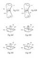
- FIG. 6Ais an exploded perspective view of an alternative re-angling device and fixation plate wherein the re-angling device is formed with a protrusion and the fixation plate is formed with a mating aperture.
- FIG. 6Bshows the alternative re-angling device and fixation plate of FIG. 6A secured in a bone of the type shown in FIG. 4A .
- FIGS. 6C to 6Fshow additional alternative embodiments of the re-angling device and fixation plate of FIG. 6A .
- FIG. 6Gis an exploded perspective view of an alternative re-angling device and fixation plate wherein the re-angling device is formed with a aperture and the fixation plate is formed with a mating protrusion.
- FIG. 7Ais an exploded perspective view of a alternative re-angling device and fixation plate being inserted into a bone of the same type shown in FIG. 4A .
- FIG. 7Bshows the alternative re-angling device and fixation plate of FIG. 7A secured in a bone of the same type as shown in FIG. 4A .
- FIG. 8shows an alternative re-angling device with a integrally formed fixation plate secured in a bone of the same type as shown in FIG. 4A .
- FIG. 9Ais a perspective view of an alternative embodiment of a re-angling device.
- FIG. 9Bshows the alternative re-angling device of FIG. 9A secured to a bone of the same type as shown in FIG. 4A by a fixation plate and fixation members.
- FIGS. 10A and 10Bshow an alternative re-angling device inserted into a bone of the type shown in FIG. 4A .
- FIGS. 10C to 10Gshow various alternative embodiments of the re-angling device of FIG. 10A .
- FIG. 10Hshows the re-angling device of FIG. 10B secured in the bone with a fixation plate and fixation members.
- FIG. 11Ais a perspective view of an alternative embodiment of the re-angling device of FIG. 3 with a hole therethrough for a total joint replacement stem.
- FIG. 11Bshows the re-angling device of FIG. 11A inserted into a bone.
- FIG. 11Cis a perspective view of an alternative embodiment of the re-angling device like that shown in FIG. 11A , inserted into a bone with the hole receiving a fixation pin.
- FIG. 11Dis a perspective view of an alternative embodiment of the re-angling device like that shown in FIG. 11A , the hole being internally threaded for receiving a screw.
- FIG. 11Eshows the re-angling device of FIG. 11E inserted into a bone and fixated with a screw through the hole.
- FIGS. 1 and 2show the anatomy of the human foot and leg, respectively. While it is contemplated that osteotomy may be in any part of the human anatomy, osteotomy is commonly performed on the metatarsal and the femur.
- FIG. 3shows a device 10 for re-angling or realigning a bone region according to the present invention.
- This device 10is sized and configured to be inserted into a gap formed in the bone region to accommodate placement of the device 10 .
- the device 10is sized and configured to re-angle or realign the bone region toward a desired anatomic position, e.g., during an osteotomy procedure.
- the re-angling device 12is generally wedge shaped, and is sized and configured to fit into a wedge-shaped gap cut into the bone region.
- the size and configuration of the re-angling device 12can vary, as long as it functionally serves to re-angle or realign the bone region in a desired manner.
- the re-angling device 12includes a generally rectangular base 16 , a pair of wedge surfaces 14 which extend from laterally opposed edges of the base 16 and meet at a point opposite the base 16 , and a pair of end surfaces 18 which extend from laterally opposed edges of the base 16 and engage one edge of each wedge surface 14 .
- an appropriately sized wedge of boneis removed from the application site, creating a wedge-shaped gap 8 , as shown in FIG. 4A .
- the application siteis chosen by the physician based on the anatomy of the patient.
- the gap 8is created using any appropriate surgical device, such as an appropriately sized and configured surgical saw.
- the device 12is then inserted into the gap 8 in the bone 6 as shown in FIG. 4B .
- the device 12may then be secured to the bone 6 .
- the device 12may be secured to the bone by any known method used in the art, for example, and not limited to bone cement, a temporary plate, and a permanent plate.
- the device 12is secured in the gap by placing a fixation plate 20 over the re-angling device 12 .
- the fixation plate 20is then attached to the bone 6 using a fixation member 24 .
- the fixation member 24preferably extends through the fixation plate 20 and into the bone 6 to secure the re-angling device 12 to the bone 6 .
- the fixation plate 20takes the form of a single fixation plate 22 that extends across the entire length of the re-angling device 12 .
- fixation plate 20could take the form of multiple fixation plates 122 , each of which extends across only a portion of the re-angling device, as shown in FIG. 4D .
- the fixation members 24comprises screws 26 , such as surgical screws.
- the fixation membersmay be chosen from a variety of fixation members known in the art.
- the fixation member 24could also be a bone staple 126 , as shown in FIG. 4E or a barbed bone staple 226 as shown in FIG. 4F .
- fixation plate 20may be desirable to provide the fixation plate 20 with at least one preformed aperture 34 through which a fixation member 24 may extend to secure the fixation plate 20 to the bone 6 .
- the aperture 34may be threaded or not threaded depending on the type of fixation member 24 to be used.
- fixation plate 20The size and shape of the device 10 , fixation plate 20 , and fixation members 24 are chosen by the physician based on each individual patient's anatomy and the type of bone in which the device is to be used.
- the device 10 , the fixation plate 20 , and the fixation members 24may be made of various materials commonly used in the prosthetic arts including, but not limited to, metals, ceramics, tantalum, polyethylene, biologic type polymers, hydroxyapetite, rubber, titanium, titanium alloys, tantalum, chrome cobalt, surgical steel, or any other total joint replacement metal and/or ceramic, bony in-growth surface, sintered glass, artificial bone, any porous metal coat, metal meshes and trabeculations, metal screens, uncemented metal or ceramic surface, other bio-compatible materials, or any combination thereof.
- the device 10 , the fixation plate 20 , and the fixation members 24may be desirable to provide with surfaces, or a portion of a surface, that allow for bony ingrowth.
- the surfaces of the device 10 , fixation plate 20 , and fixation members 24could be covered with biological bone substitute or biological stimulators for example, but not limited to hydroxygretite, calcium phosphate, calcium sulfate, or one of the bone morphogenic stimulators.
- the surfaces of device 10 , the fixation plate 20 , and the fixation members 24could be covered with surface texturing to induce bony in-growth.
- the surface texturingcan comprise, e.g., through holes, and/or various surface patterns, and/or various surface textures, and/or pores, or combinations thereof.
- the device 10can be coated or wrapped or surfaced treated to provide the surface texturing, or it can be formed from a material that itself inherently possesses a surface conducing to bony in-growth, such as a porous mesh, hydroxyapetite, or other porous surface.
- the device 10may further be desirably for the device 10 to be covered with various coatings such as antimicrobial, antithrombogenic, and osteoinductive agents, or a combination thereof.
- the re-angling device 10 described abovemay be fixed by one or more fixation members inserted through the alternative re-angling device 112 as shown in FIGS. 5A and 5B .
- the re-angling device 112may take generally the same form as described above. However, in such an embodiment the need for a fixation plate 20 is eliminated.
- an appropriately sized wedge of boneis removed from the application site, creating a wedge-shaped gap 8 , as shown in FIG. 4A .
- the wedge-shaped gap 8is formed using any appropriate surgical device, such as an appropriately sized and configured surgical saw.
- the application siteis chosen by the physician based on the anatomy of the patient.
- the size and particular configuration of the alternative re-angling device 112is also selected by the physician based on the anatomy of the patient.
- the alternative re-angling device 112may then be inserted into the gap 8 in the bone 6 and secured to the bone 8 by a fixation member 24 as shown in FIGS. 5A .
- the fixation member 24comprises a threaded screw 26 .
- the fixation member 24is secured using any appropriate surgical devices, such as an appropriately sized and configured surgical screwdriver. As shown in FIG. 5A , the screw 26 is screwed though the re-angling device 112 and into the bone 6 . It is further contemplated that multiple fixation members 24 could be utilized to fasten a single re-angling device 112 , as shown in FIG. 5B . It may be desirable, but not necessary, to have a pilot hole in the re-angling device 112 to aid in insertion of the at least one fixation member 24 .
- the re-angling devicecould be preformed with an aperture, such as a pilot hole 28 , as shown in FIG. 5A .
- the pilot hole 28could be drilled in the device 112 by the surgeon either before or after inserting the re-angling device 112 in the bone 6 .
- the re-angling device 112 and fixation members 24may be formed of any appropriate prosthetic material as describe above, and if desirable may include surfaces adapted to promote bony-in-growth as also described above.
- a re-angling device 10may be removably coupled to a fixation plate 20 .
- the re-angling device 112 and fixation plate 322may take generally the same form as described above.
- the re-angling device 112includes a first surface geometry 30 and the fixation plate 20 includes a second surface geometry 32 that nests or mates with the first surface geometry 30 .
- the first surface geometrycomprises a female aperture 30 and the second surface geometry comprises a mating male protrusion 32 .
- the protrusion 32is sized and configured to be received in the aperture 30 formed in the re-angling device 112 .
- the mating male and female configurationsmay be reversed. That is, the first surface geometry on the device can comprise a male projection and the second surface geometry on the device comprises a mating female aperture.
- the protrusion 32 and the aperture 30each take a tapered rectangular shape.
- the protrusion 32 and aperture 30may take any shape including, but not limited to square (see FIG. 6C ), morse taper, triangular (see FIG. 6D ), star-shaped (see FIG. 6E ), or round (see FIG. 6F ).
- the re-angling device 112 and the fixation plate 322may be coupled prior to inserting the re-angling device 112 into the bone 6 .
- the re-angling device 112may first be inserted into the bone 6 , then the fixation plate 322 may be coupled to the re-angling device 112 .
- fixation plate 322is then fixed to the bone 6 by at least one fixation member 24 , as shown in FIG. 6B and described in further detail above.
- fixation member 24takes the form of a screw 26 , however it should be understood that the fixation member 24 may take any form.
- the re-angling device 212may be formed with a protrusion 38 and the fixation plate 422 may be formed with a mating aperture 36 , as shown in FIG. 6H .
- the illustrated embodimentincludes a rectangular tapered protrusion 38 and a generally rectangular aperture 36 , however as described above, the aperture 36 and protrusion 38 may take any mating shape.
- an appropriately sized wedge of boneis removed from the application site, creating a wedge-shaped gap 8 , as shown in FIG. 4A .
- the application siteis chosen by the physician based on the anatomy of the patient.
- the re-angling device 112 , 212 , fixation plate 322 , 422 and fixation members 24may be formed of any appropriate prosthetic material as describe above, and if desirable may include surfaces adapted to promote bony-in-growth as also described above.
- both the re-angling device 10 and the fixation plate 20may be preformed with an aperture.
- an aperture 530is formed in the re-angling device 112 and an aperture 136 is formed in the fixation plate 422 .
- the fixation plate 422may be fixed to the re-angling device 112 via a fixation member 24 such as a screw 26 , as shown in FIG. 7B .
- the aperture 136 in the fixation plate 422 and the aperture 530 in the re-angling device 112could be threaded as shown in FIG. 7A , or unthreaded. It is also contemplated that the aperture 136 in the fixation plate 422 could be threaded while the aperture 530 in the re-angling device 112 is not threaded, or vice versa.
- fixation plate 422may be desirable, although not necessary, to provide the fixation plate 422 with at least one aperture 34 through which the fixation members 24 may extend as shown in FIG. 7A . It may be desirable, but not necessary, to provide the at least one aperture 34 with internal threads as shown in FIG. 7A .
- the re-angling device 112is generally wedge-shaped, as described above.
- the size and specific configuration of the re-angling device 112 , fixation plate 422 , and fixation members 24are chosen by the physician based on each individual patient's anatomy and the type of bone in which the device 112 is to be used.
- the re-angling device 112 and the fixation plate 422may be attached prior to inserting the re-angling device 112 into the bone 6 , or after the re-angling device 112 has been inserted into the bone 6 .
- an appropriately sized wedge of boneis removed from the application site, creating a wedge-shaped gap 8 , as shown in FIG. 4A .
- the wedge-shaped gap 8is formed using any appropriate surgical device, such as an appropriately sized and configured surgical saw.
- the application siteis chosen by the physician based on the anatomy of the patient.
- the size and particular configuration of the re-angling deviceis also selected by the physician based on the anatomy of the patient.
- the re-angling device 112is then inserted into the gap 8 in the bone 6 and secured to the bone 6 by a fixation member 24 as shown in FIGS. 7B .
- the fixation member 24comprises a threaded screw 26 , however it should be understood that any appropriate fastener may be utilized.
- the fixation member 24is secured using any appropriate surgical devices, such as an appropriately sized and configured surgical screwdriver. As shown in FIG. 7B , the screw 26 is screwed though the fixation member 422 and into the bone 6 .
- fixation plate 422 and fixation members 24may be formed of any appropriate prosthetic material as describe above, and if desirable may include surfaces adapted to promote bony-in-growth as also described above.
- the re-angling device 10 and the fixation plate 20are integrally formed as a single device 312 , as shown in FIG. 8 .
- the alternative re-angling device 312may take generally the same wedge-shaped configuration as described above.
- an appropriately sized wedge of bone 6is removed from the application site, creating a wedge-shaped gap 8 , as shown above in FIG. 4A .
- the application siteis chosen by the physician based on the anatomy of the patient.
- the device 312is then inserted into the gap 8 in the bone as shown in FIG. 8 and secured to the bone 6 .
- the re-angling device 312may be fixed to the bone through at least one fixation member 20 .
- the fixation member 20takes the form of a screw 26 .
- the fixation member 20may comprise any suitable fixation member, including, by means of example a surgical screw or a surgical staple. As described above, and shown in FIG.
- the size and the particular configuration of the re-angling device 312are preferably chosen by the physical based on the anatomy of the patient being treated.
- the re-angling device 312 and fixation members 24may be formed of any appropriate prosthetic material as describe above, and if desirable may include surfaces adapted to promote bony-in-growth as also described above.
- the re-angling device 412may be formed such that the bone 6 may be angled in two planes.
- the configuration of the re-angling deviceis similar to that shown in FIG. 3 and described above, however the base 416 is generally trapezoidal, rather than rectangular.
- an appropriately sized wedge of bone 6is removed from the application site, creating a wedge-shaped gap 8 , as shown above in FIG. 4A .
- the application siteis chosen by the physician based on the anatomy of the patient.
- the device 412is then inserted into the gap 8 in the bone as shown in FIG. 9B and secured to the bone 6 .
- the re-angling device 412may be fixed to the bone through at least one fixation member 20 .
- the fixation member 20takes the form of a screw 26 .
- the fixation member 20may comprise any suitable fixation member, including, by means of example a surgical screw or a surgical staple. As described above, and shown in FIG.
- the size and the particular configuration of the re-angling device 412are preferably chosen by the physical based on the anatomy of the patient being treated.
- the re-angling device and fixation membersmay be formed of any appropriate prosthetic material as describe above, and if desirable may include surfaces adapted to promote bony-in-growth as also described above.
- the re-angling device 512may include at least one intramedullary post 40 , as shown in FIG. 10A .
- the intramedullary post 40may extend into the bone 6 to further secure the re-angling device 512 within the bone 6 .
- an appropriately sized wedge of bone 6is removed from the application site, creating a wedge-shaped gap 8 , as shown above in FIG. 4A .
- At least one aperturemay be formed in the bone 6 , the aperture being adapted to accept the at least one intramedulary post 40 .
- the application siteis chosen by the physician based on the anatomy of the patient.
- the device 512is then inserted into the gap 8 in the bone as shown in FIG. 8 and secured to the bone 6 .
- the size and the particular configuration of the re-angling device 512are preferably chosen by the physical based on the anatomy of the patient being treated.
- the re-angling device 512could be formed with a pair of posts 40 , as shown in FIG. 10B .
- the post 40 on the re-angling device 512could take any shape.
- the postcould be square (see FIG. 10C ), star-shaped (see FIG. 10D ), triangular (see FIG. 10E ), rounded (see FIG. 10F ) or pointed (see FIG. 10G ).
- the re-angling device 512may be formed of any appropriate prosthetic material as describe above, and if desirable may include surfaces adapted to promote bony-in-growth as also described above.
- any of the re-angling devices described abovemay be formed with a hole 44 therethrough as shown in FIG. 11A .
- the hole 44may be sized and configured for the particular application.
- the hole 44may be sized and configured such that when the re-angling device 612 is inserted into the bone 6 , the stem 46 of a total joint replacement 52 may be inserted through the hole 44 , as shown in FIG. 11B .
- the hole 44may be sized and configured for receiving a pin 48 , as shown in FIG. 11C .
- the hole 44may be internally threaded, as shown in FIG. 11D , and be sized and configured for receiving a screw 50 , as shown in FIGS. 11D and 11E .
- the basic configuration of the re-angling device 612is the same as described above. The particular size and configuration of the device 612 is determined by the physician based on the bone being treated and the anatomy of the patient.
- an application siteis chosen by the physician based on the anatomy of the patient.
- An appropriately sized wedge of boneis removed from the application site, creating a wedge-shaped gap 8 , as shown in FIG. 4A .
- the device 612may then be inserted into the gap in the bone as shown in FIG. 11B .
- the device 612may then be secured to the bone 6 by any known method used in the art.
- the device 612may be secured in the gap 8 by placing a fixation plate 20 over the re-angling device 612 , as FIG. 11B shows.
- the fixation plate 20can be attached to the bone 6 using at least one fixation member 24 .
- the fixation member 24preferably extends through the fixation plate 20 and into the bone 6 to secure the re-angling device 612 to the bone 6 .
- the fixation member 24comprises at least one screw, however any appropriate fixation member 24 may be utilized without departing from the invention.
- the re-angling device 612is oriented so that the hole 44 receives the stem 46 of a total joint replacement 52 .
- the device 612may be oriented so that the hole receives a pin 48 ( FIG. 11C ) or a screw 50 ( FIG. 11E ), which can be installed using standard surgical procedures known in the art.
- a fixation plate 20(as shown in FIG. 11B ) need not be provided, but optionally, it can be, if additional fixation is desired.
- fixation plate 20 or platesmay be provided with at least one preformed aperture 34 through which a fixation member 24 may extend to secure the fixation plate 20 to the bone 6 , as shown in FIGS. 6A and 6B .
- the aperture 34may be threaded or not threaded.
- the re-angling device 612 and fixation members 20 , 24 , 46 , 48 , and 50may be formed of any appropriate prosthetic material as describe above, and if desirable may include surfaces adapted to promote bony-in-growth as also described above.
Landscapes
- Health & Medical Sciences (AREA)
- Orthopedic Medicine & Surgery (AREA)
- Surgery (AREA)
- Life Sciences & Earth Sciences (AREA)
- Heart & Thoracic Surgery (AREA)
- Nuclear Medicine, Radiotherapy & Molecular Imaging (AREA)
- Engineering & Computer Science (AREA)
- Biomedical Technology (AREA)
- Neurology (AREA)
- Medical Informatics (AREA)
- Molecular Biology (AREA)
- Animal Behavior & Ethology (AREA)
- General Health & Medical Sciences (AREA)
- Public Health (AREA)
- Veterinary Medicine (AREA)
- Surgical Instruments (AREA)
Abstract
Description
Claims (8)
Priority Applications (2)
| Application Number | Priority Date | Filing Date | Title |
|---|---|---|---|
| US14/615,137US9861404B2 (en) | 2008-01-04 | 2015-02-05 | Devices, systems and methods for re-alignment of bone |
| US15/847,436US20180193070A1 (en) | 2008-01-04 | 2017-12-19 | Devices, systems, and methods for re-alignment of bone |
Applications Claiming Priority (3)
| Application Number | Priority Date | Filing Date | Title |
|---|---|---|---|
| US12/006,720US20090177203A1 (en) | 2008-01-04 | 2008-01-04 | Devices, systems and methods for re-alignment of bone |
| US13/747,031US20130138154A1 (en) | 2008-01-04 | 2013-01-22 | Devices, systems and methods for re-alignment of bone |
| US14/615,137US9861404B2 (en) | 2008-01-04 | 2015-02-05 | Devices, systems and methods for re-alignment of bone |
Related Parent Applications (1)
| Application Number | Title | Priority Date | Filing Date |
|---|---|---|---|
| US13/747,031ContinuationUS20130138154A1 (en) | 2008-01-04 | 2013-01-22 | Devices, systems and methods for re-alignment of bone |
Related Child Applications (1)
| Application Number | Title | Priority Date | Filing Date |
|---|---|---|---|
| US15/847,436ContinuationUS20180193070A1 (en) | 2008-01-04 | 2017-12-19 | Devices, systems, and methods for re-alignment of bone |
Publications (2)
| Publication Number | Publication Date |
|---|---|
| US20150164564A1 US20150164564A1 (en) | 2015-06-18 |
| US9861404B2true US9861404B2 (en) | 2018-01-09 |
Family
ID=40845176
Family Applications (4)
| Application Number | Title | Priority Date | Filing Date |
|---|---|---|---|
| US12/006,720AbandonedUS20090177203A1 (en) | 2008-01-04 | 2008-01-04 | Devices, systems and methods for re-alignment of bone |
| US13/747,031AbandonedUS20130138154A1 (en) | 2008-01-04 | 2013-01-22 | Devices, systems and methods for re-alignment of bone |
| US14/615,137ActiveUS9861404B2 (en) | 2008-01-04 | 2015-02-05 | Devices, systems and methods for re-alignment of bone |
| US15/847,436AbandonedUS20180193070A1 (en) | 2008-01-04 | 2017-12-19 | Devices, systems, and methods for re-alignment of bone |
Family Applications Before (2)
| Application Number | Title | Priority Date | Filing Date |
|---|---|---|---|
| US12/006,720AbandonedUS20090177203A1 (en) | 2008-01-04 | 2008-01-04 | Devices, systems and methods for re-alignment of bone |
| US13/747,031AbandonedUS20130138154A1 (en) | 2008-01-04 | 2013-01-22 | Devices, systems and methods for re-alignment of bone |
Family Applications After (1)
| Application Number | Title | Priority Date | Filing Date |
|---|---|---|---|
| US15/847,436AbandonedUS20180193070A1 (en) | 2008-01-04 | 2017-12-19 | Devices, systems, and methods for re-alignment of bone |
Country Status (1)
| Country | Link |
|---|---|
| US (4) | US20090177203A1 (en) |
Cited By (29)
| Publication number | Priority date | Publication date | Assignee | Title |
|---|---|---|---|---|
| US10349982B2 (en) | 2011-11-01 | 2019-07-16 | Nuvasive Specialized Orthopedics, Inc. | Adjustable magnetic devices and methods of using same |
| US10433888B2 (en)* | 2013-12-20 | 2019-10-08 | Crossroads Extremity Systems, Llc | Bone plates with dynamic elements |
| US10478232B2 (en) | 2009-04-29 | 2019-11-19 | Nuvasive Specialized Orthopedics, Inc. | Interspinous process device and method |
| US10492841B2 (en) | 2014-07-10 | 2019-12-03 | Crossroads Extremity Systems, Llc | Bone implant and means of insertion |
| US10617453B2 (en) | 2015-10-16 | 2020-04-14 | Nuvasive Specialized Orthopedics, Inc. | Adjustable devices for treating arthritis of the knee |
| US10646262B2 (en) | 2011-02-14 | 2020-05-12 | Nuvasive Specialized Orthopedics, Inc. | System and method for altering rotational alignment of bone sections |
| US10660675B2 (en) | 2010-06-30 | 2020-05-26 | Nuvasive Specialized Orthopedics, Inc. | External adjustment device for distraction device |
| US10729470B2 (en) | 2008-11-10 | 2020-08-04 | Nuvasive Specialized Orthopedics, Inc. | External adjustment device for distraction device |
| US10743794B2 (en) | 2011-10-04 | 2020-08-18 | Nuvasive Specialized Orthopedics, Inc. | Devices and methods for non-invasive implant length sensing |
| US10751094B2 (en) | 2013-10-10 | 2020-08-25 | Nuvasive Specialized Orthopedics, Inc. | Adjustable spinal implant |
| US10806496B2 (en)* | 2015-11-16 | 2020-10-20 | Oxford University Innovation Limited | Proximal tibial osteotomy system |
| US10835290B2 (en) | 2015-12-10 | 2020-11-17 | Nuvasive Specialized Orthopedics, Inc. | External adjustment device for distraction device |
| US10918425B2 (en) | 2016-01-28 | 2021-02-16 | Nuvasive Specialized Orthopedics, Inc. | System and methods for bone transport |
| US11090094B2 (en)* | 2018-06-01 | 2021-08-17 | Ehsan JAZINI | System and method for facilitating osteotomy of the pelvic |
| US20210282823A1 (en)* | 2020-03-10 | 2021-09-16 | Arthrex, Inc. | Internal beam plates and associated instrumentation for performing surgical methods |
| US20210353341A1 (en)* | 2016-03-23 | 2021-11-18 | Wright Medical Technology, Inc. | Wedge plates and methods of use |
| US11191579B2 (en) | 2012-10-29 | 2021-12-07 | Nuvasive Specialized Orthopedics, Inc. | Adjustable devices for treating arthritis of the knee |
| US11202626B2 (en) | 2014-07-10 | 2021-12-21 | Crossroads Extremity Systems, Llc | Bone implant with means for multi directional force and means of insertion |
| US11202707B2 (en) | 2008-03-25 | 2021-12-21 | Nuvasive Specialized Orthopedics, Inc. | Adjustable implant system |
| US11234849B2 (en) | 2006-10-20 | 2022-02-01 | Nuvasive Specialized Orthopedics, Inc. | Adjustable implant and method of use |
| US11246694B2 (en) | 2014-04-28 | 2022-02-15 | Nuvasive Specialized Orthopedics, Inc. | System for informational magnetic feedback in adjustable implants |
| US11317951B2 (en) | 2013-12-20 | 2022-05-03 | Crossroads Extremity Systems, Llc | Bone plates with dynamic elements |
| US11357549B2 (en) | 2004-07-02 | 2022-06-14 | Nuvasive Specialized Orthopedics, Inc. | Expandable rod system to treat scoliosis and method of using the same |
| USD961081S1 (en) | 2020-11-18 | 2022-08-16 | Crossroads Extremity Systems, Llc | Orthopedic implant |
| US11439449B2 (en) | 2014-12-26 | 2022-09-13 | Nuvasive Specialized Orthopedics, Inc. | Systems and methods for distraction |
| US11612416B2 (en) | 2015-02-19 | 2023-03-28 | Nuvasive Specialized Orthopedics, Inc. | Systems and methods for vertebral adjustment |
| US11864753B2 (en) | 2017-02-06 | 2024-01-09 | Crossroads Extremity Systems, Llc | Implant inserter |
| US12059183B2 (en) | 2020-07-31 | 2024-08-13 | Crossroads Extremity Systems, Llc | Bone plates with dynamic elements and screws |
| US20250235317A1 (en)* | 2023-01-26 | 2025-07-24 | Jason D. Toranto | Mandibular reconstruction systems and methods |
Families Citing this family (58)
| Publication number | Priority date | Publication date | Assignee | Title |
|---|---|---|---|---|
| US20090112262A1 (en) | 2007-10-30 | 2009-04-30 | Scott Pool | Skeletal manipulation system |
| US20090177203A1 (en) | 2008-01-04 | 2009-07-09 | Inbone Technologies, Inc. | Devices, systems and methods for re-alignment of bone |
| US9044282B2 (en) | 2008-06-24 | 2015-06-02 | Extremity Medical Llc | Intraosseous intramedullary fixation assembly and method of use |
| US9017329B2 (en) | 2008-06-24 | 2015-04-28 | Extremity Medical, Llc | Intramedullary fixation assembly and method of use |
| US8303589B2 (en) | 2008-06-24 | 2012-11-06 | Extremity Medical Llc | Fixation system, an intramedullary fixation assembly and method of use |
| US9289220B2 (en) | 2008-06-24 | 2016-03-22 | Extremity Medical Llc | Intramedullary fixation assembly and method of use |
| US8328806B2 (en) | 2008-06-24 | 2012-12-11 | Extremity Medical, Llc | Fixation system, an intramedullary fixation assembly and method of use |
| US8343199B2 (en) | 2008-06-24 | 2013-01-01 | Extremity Medical, Llc | Intramedullary fixation screw, a fixation system, and method of fixation of the subtalar joint |
| US8313487B2 (en) | 2008-06-24 | 2012-11-20 | Extremity Medical Llc | Fixation system, an intramedullary fixation assembly and method of use |
| US11241257B2 (en) | 2008-10-13 | 2022-02-08 | Nuvasive Specialized Orthopedics, Inc. | Spinal distraction system |
| US8795340B2 (en)* | 2008-11-07 | 2014-08-05 | Globus Medical, Inc. | Vertical inline plate |
| US8197490B2 (en) | 2009-02-23 | 2012-06-12 | Ellipse Technologies, Inc. | Non-invasive adjustable distraction system |
| JP5751642B2 (en) | 2009-09-04 | 2015-07-22 | エリプス テクノロジーズ, インク.Ellipse Technologies, Inc. | Bone growth apparatus and method |
| FR2956312B1 (en)* | 2010-02-15 | 2013-01-25 | Implants Internat Ltd | EQUIPMENT FOR FIXING TWO PARTS OF A BONE TO EACH OTHER |
| US8444699B2 (en)* | 2010-02-18 | 2013-05-21 | Biomet Manufacturing Corp. | Method and apparatus for augmenting bone defects |
| US8998903B2 (en) | 2010-03-10 | 2015-04-07 | Orthohelix Surgical Designs, Inc. | Wedge opening osteotomy plate |
| WO2012021378A2 (en) | 2010-08-09 | 2012-02-16 | Ellipse Technologies, Inc. | Maintenance feature in magnetic implant |
| US9017412B2 (en) | 2011-04-29 | 2015-04-28 | Life Spine, Inc. | Spinal interbody implant with bone screw retention |
| US9668783B2 (en)* | 2011-09-06 | 2017-06-06 | Atul Goel | Devices and method for treatment of spondylotic disease |
| US20130338714A1 (en) | 2012-06-15 | 2013-12-19 | Arvin Chang | Magnetic implants with improved anatomical compatibility |
| US9433452B2 (en)* | 2012-08-03 | 2016-09-06 | Nextremity Solutions, Llc | Bone fixation device and method |
| DE202012103384U1 (en) | 2012-09-05 | 2012-09-24 | Signus Medizintechnik Gmbh | Pelvic ring implant |
| US9044281B2 (en) | 2012-10-18 | 2015-06-02 | Ellipse Technologies, Inc. | Intramedullary implants for replacing lost bone |
| US9179938B2 (en) | 2013-03-08 | 2015-11-10 | Ellipse Technologies, Inc. | Distraction devices and method of assembling the same |
| WO2014147604A2 (en)* | 2013-03-19 | 2014-09-25 | Quadrante Do Futuro, Unipessoal Lda | Dynamic osteotomy plate including devices, apparatus and methods using such a plate |
| US10226242B2 (en) | 2013-07-31 | 2019-03-12 | Nuvasive Specialized Orthopedics, Inc. | Noninvasively adjustable suture anchors |
| US9801734B1 (en) | 2013-08-09 | 2017-10-31 | Nuvasive, Inc. | Lordotic expandable interbody implant |
| US9889014B2 (en) | 2014-02-06 | 2018-02-13 | Life Spine, Inc. | Implant for bone fixation |
| US9877759B2 (en) | 2014-02-06 | 2018-01-30 | Life Spine, Inc. | Foot implant for bone fixation |
| JP6296466B2 (en)* | 2014-03-26 | 2018-03-20 | オリンパステルモバイオマテリアル株式会社 | Bone plate and bone plate system |
| KR101632652B1 (en)* | 2014-04-18 | 2016-07-01 | 백혜선 | A fixation tool for opening wedge high tibial osteotomy |
| KR101740905B1 (en)* | 2014-04-18 | 2017-05-29 | 백혜선 | A fixation tool for opening wedge high tibial osteotomy |
| US20150335367A1 (en)* | 2014-05-20 | 2015-11-26 | Neutin Orthopedics, LLC | Medical grade cotton and evans osteotomy wedges |
| US10159517B2 (en) | 2014-07-07 | 2018-12-25 | Stryker European Holdings I, Llc | Bone plate with attachable wedge |
| US10383733B2 (en) | 2014-10-22 | 2019-08-20 | Biomet C.V. | Method and apparatus for bone fixation |
| KR102588501B1 (en) | 2014-10-23 | 2023-10-11 | 누베이시브 스페셜라이즈드 오소페딕스, 인크. | Remotely adjustable interactive bone reshaping implant |
| US20160184099A1 (en)* | 2014-12-29 | 2016-06-30 | Yechiel Gotfried | Orthopedic implants |
| USD840035S1 (en) | 2015-01-07 | 2019-02-05 | Nextremity Solutions, Inc. | Bone fixation implant |
| US10376367B2 (en) | 2015-07-02 | 2019-08-13 | First Ray, LLC | Orthopedic fasteners, instruments and methods |
| WO2017041065A1 (en) | 2015-09-04 | 2017-03-09 | Centric Medical Llc (A Delaware Limited Liability Company) | Small bone orthopedic implants |
| US10702290B2 (en) | 2015-11-02 | 2020-07-07 | First Ray, LLC | Orthopedic fastener, retainer, and guide |
| WO2017139548A1 (en) | 2016-02-10 | 2017-08-17 | Nuvasive Specialized Orthopedics, Inc. | Systems and methods for controlling multiple surgical variables |
| US10617457B2 (en) | 2016-03-03 | 2020-04-14 | Stryker European Holdings I, Llc | Forceps for handling/holding a mobile wedge plate |
| RU2621949C1 (en)* | 2016-06-02 | 2017-06-08 | Общество с ограниченной ответственностью "Медико-инженерный центр сплавов с памятью формы" | Combined implant and instruments for its installation |
| US10779816B2 (en) | 2016-07-07 | 2020-09-22 | Medline Industries, Inc. | Orthopedic implant, method, and kit |
| US10543028B2 (en)* | 2017-02-06 | 2020-01-28 | Biomet Manufacturing, Llc | Adjustable wedge |
| EP3579762B1 (en) | 2017-02-07 | 2024-06-26 | Crossroads Extremity Systems, LLC | Counter-torque implant |
| US11364128B2 (en)* | 2017-06-12 | 2022-06-21 | Medline Industries, Lp | Arthritis plate |
| US10932823B2 (en) | 2017-10-25 | 2021-03-02 | Life Spine, Inc. | Facet plate for implant expulsion prevention and method of installation |
| CA3112267A1 (en)* | 2018-08-24 | 2020-02-27 | Laboratoires Bodycad Inc. | Patient-specific surgical tools for knee osteotomies |
| US20220008106A1 (en)* | 2018-12-27 | 2022-01-13 | Wright Medical Technology, Inc. | Bone fixation implants |
| JP2022519380A (en) | 2019-02-07 | 2022-03-23 | ニューベイシブ スペシャライズド オーソペディックス,インコーポレイテッド | Ultrasonic communication in medical devices |
| US11589901B2 (en) | 2019-02-08 | 2023-02-28 | Nuvasive Specialized Orthopedics, Inc. | External adjustment device |
| US12213708B2 (en) | 2020-09-08 | 2025-02-04 | Nuvasive Specialized Orthopedics, Inc. | Remote control module for adjustable implants |
| US20220265326A1 (en) | 2021-02-23 | 2022-08-25 | Nuvasive Specialized Orthopedics, Inc. | Adjustable implant, system and methods |
| US11737787B1 (en) | 2021-05-27 | 2023-08-29 | Nuvasive, Inc. | Bone elongating devices and methods of use |
| EP4380480A1 (en) | 2021-08-03 | 2024-06-12 | NuVasive Specialized Orthopedics, Inc. | Adjustable implant |
| US20230310047A1 (en)* | 2022-03-31 | 2023-10-05 | Medartis Ag | Bone wedge implant and method |
Citations (41)
| Publication number | Priority date | Publication date | Assignee | Title |
|---|---|---|---|---|
| US4347234A (en) | 1978-01-09 | 1982-08-31 | Merck Patent Gesellschaft Mit Beschrankter Haftung | Medicinally useful, shaped mass of collagen resorbable in the body |
| US4421112A (en) | 1982-05-20 | 1983-12-20 | Minnesota Mining And Manufacturing Company | Tibial osteotomy guide assembly and method |
| US5053039A (en) | 1989-09-14 | 1991-10-01 | Intermedics Orthopedics | Upper tibial osteotomy system |
| US5569250A (en) | 1994-03-01 | 1996-10-29 | Sarver; David R. | Method and apparatus for securing adjacent bone portions |
| US5620448A (en) | 1995-03-24 | 1997-04-15 | Arthrex, Inc. | Bone plate system for opening wedge proximal tibial osteotomy |
| US5766251A (en) | 1992-03-13 | 1998-06-16 | Tomihisa Koshino | Wedge-shaped spacer for correction of deformed extremities |
| US5888223A (en) | 1995-12-08 | 1999-03-30 | Bray, Jr.; Robert S. | Anterior stabilization device |
| US6008433A (en) | 1998-04-23 | 1999-12-28 | Stone; Kevin R. | Osteotomy wedge device, kit and methods for realignment of a varus angulated knee |
| US6030389A (en) | 1997-08-04 | 2000-02-29 | Spinal Concepts, Inc. | System and method for stabilizing the human spine with a bone plate |
| US6086593A (en)* | 1998-06-30 | 2000-07-11 | Bonutti; Peter M. | Method and apparatus for use in operating on a bone |
| US6099531A (en)* | 1998-08-20 | 2000-08-08 | Bonutti; Peter M. | Changing relationship between bones |
| US6203546B1 (en) | 1999-07-27 | 2001-03-20 | Macmahon Edward B | Method and apparatus for medial tibial osteotomy |
| US6235059B1 (en) | 1996-04-03 | 2001-05-22 | Scient'x (Societe A Responsabilite Limitee) | Intersomatic setting and fusion system |
| US6432106B1 (en) | 1999-11-24 | 2002-08-13 | Depuy Acromed, Inc. | Anterior lumbar interbody fusion cage with locking plate |
| US20020120335A1 (en) | 2001-02-28 | 2002-08-29 | Angelucci Christopher M. | Laminoplasty implants and methods of use |
| US6544266B1 (en) | 1999-01-22 | 2003-04-08 | Australian Surgical Design And Manufacture Pty, Ltd. | Method and apparatus for delivering bio-active compounds to specified sites in the body |
| US6635087B2 (en) | 2001-08-29 | 2003-10-21 | Christopher M. Angelucci | Laminoplasty implants and methods of use |
| US20040193269A1 (en) | 2003-03-31 | 2004-09-30 | Depuy Acromed, Inc. | Anterior lumbar interbody fusion cage with locking plate |
| US6823871B2 (en) | 2000-06-01 | 2004-11-30 | Arthrex, Inc. | Allograft bone or synthetic wedges for osteotomy |
| US7108697B2 (en) | 2002-04-23 | 2006-09-19 | Citieffe S.R.L. | Stabilizing support for opening- and closing-wedge osteotomies |
| US20070198016A1 (en)* | 2006-02-21 | 2007-08-23 | Osteomed, L.P. | Compression stabilizing spacers |
| US20070239278A1 (en) | 2006-04-06 | 2007-10-11 | Sdgi Holdings, Inc. | Intervertebral prosthetic devices and methods |
| US20080108997A1 (en) | 2006-09-12 | 2008-05-08 | Pioneer Surgical Technology, Inc. | Mounting Devices for Fixation Devices and Insertion Instruments Used Therewith |
| US20080147073A1 (en)* | 2005-01-31 | 2008-06-19 | Ammann Kelly G | Method and apparatus for performing an open wedge, high tibial osteotomy |
| US20090043308A1 (en)* | 2007-08-07 | 2009-02-12 | Horacek Justin L | Method and apparatus for performing an open wedge osteotomy |
| US20090082770A1 (en) | 2007-09-25 | 2009-03-26 | Normed Medizin-Technik Vertriebs-Gmbh | Medical foot implant and system |
| US20090177203A1 (en) | 2008-01-04 | 2009-07-09 | Inbone Technologies, Inc. | Devices, systems and methods for re-alignment of bone |
| US7594931B2 (en) | 2001-07-13 | 2009-09-29 | Ldr Medical | Vertebral cage device with modular fixation |
| US20090264935A1 (en) | 2005-10-26 | 2009-10-22 | Pierre Imbert | Surgical Implant Used in Osteotomy |
| US20100152782A1 (en) | 2006-02-27 | 2010-06-17 | Biomet Manufactring Corp. | Patient Specific High Tibia Osteotomy |
| US7744630B2 (en) | 2005-11-15 | 2010-06-29 | Zimmer Spine, Inc. | Facet repair and stabilization |
| US20110087295A1 (en) | 2009-10-12 | 2011-04-14 | University Of Utah | Bone fixation systems |
| US7935119B2 (en) | 2005-01-31 | 2011-05-03 | Ibalance Medical, Inc. | Method for performing an open wedge, high tibial osteotomy |
| WO2011082343A1 (en) | 2009-12-31 | 2011-07-07 | Tristar Medical Solutions, Llc | Method and apparatus for fusing the bones of a joint |
| US7976566B2 (en) | 1994-03-28 | 2011-07-12 | Warsaw Orthopedic, Inc. | Apparatus for insertion into an implantation space |
| US20110213376A1 (en) | 2010-02-26 | 2011-09-01 | Biomet Sports Medicine, Llc | Patient-Specific Osteotomy Devices and Methods |
| US20120130501A1 (en) | 2004-03-03 | 2012-05-24 | Cachia Victor V | Catheter deliverable foot implant and method of delivering the same |
| US20120184959A1 (en) | 2010-03-10 | 2012-07-19 | Orthohelix Surgical Designs, Inc. | Wedge opening osteotomy plate |
| US20120191211A1 (en) | 2011-01-20 | 2012-07-26 | Tim Drozd | Foot and ankle implant and associated method |
| US20120232596A1 (en) | 2009-11-05 | 2012-09-13 | Christiano Hossri Ribeiro | Multi-adjustable plate for osteotomy |
| US8784457B2 (en) | 2010-10-14 | 2014-07-22 | Michael E Graham | Implant for correcting skeletal mechanics |
Family Cites Families (3)
| Publication number | Priority date | Publication date | Assignee | Title |
|---|---|---|---|---|
| US20020038123A1 (en)* | 2000-09-20 | 2002-03-28 | Visotsky Jeffrey L. | Osteotomy implant |
| US8388690B2 (en)* | 2003-10-03 | 2013-03-05 | Linvatec Corporation | Osteotomy system |
| US9889014B2 (en)* | 2014-02-06 | 2018-02-13 | Life Spine, Inc. | Implant for bone fixation |
- 2008
- 2008-01-04USUS12/006,720patent/US20090177203A1/ennot_activeAbandoned
- 2013
- 2013-01-22USUS13/747,031patent/US20130138154A1/ennot_activeAbandoned
- 2015
- 2015-02-05USUS14/615,137patent/US9861404B2/enactiveActive
- 2017
- 2017-12-19USUS15/847,436patent/US20180193070A1/ennot_activeAbandoned
Patent Citations (45)
| Publication number | Priority date | Publication date | Assignee | Title |
|---|---|---|---|---|
| US4347234A (en) | 1978-01-09 | 1982-08-31 | Merck Patent Gesellschaft Mit Beschrankter Haftung | Medicinally useful, shaped mass of collagen resorbable in the body |
| US4421112A (en) | 1982-05-20 | 1983-12-20 | Minnesota Mining And Manufacturing Company | Tibial osteotomy guide assembly and method |
| US5053039A (en) | 1989-09-14 | 1991-10-01 | Intermedics Orthopedics | Upper tibial osteotomy system |
| US5766251A (en) | 1992-03-13 | 1998-06-16 | Tomihisa Koshino | Wedge-shaped spacer for correction of deformed extremities |
| US5569250A (en) | 1994-03-01 | 1996-10-29 | Sarver; David R. | Method and apparatus for securing adjacent bone portions |
| US7976566B2 (en) | 1994-03-28 | 2011-07-12 | Warsaw Orthopedic, Inc. | Apparatus for insertion into an implantation space |
| US5749875A (en) | 1995-03-24 | 1998-05-12 | Arthrex, Inc. | Bone plate system for proximal tibial osteotomy |
| US5620448A (en) | 1995-03-24 | 1997-04-15 | Arthrex, Inc. | Bone plate system for opening wedge proximal tibial osteotomy |
| US5888223A (en) | 1995-12-08 | 1999-03-30 | Bray, Jr.; Robert S. | Anterior stabilization device |
| US6235059B1 (en) | 1996-04-03 | 2001-05-22 | Scient'x (Societe A Responsabilite Limitee) | Intersomatic setting and fusion system |
| US6030389A (en) | 1997-08-04 | 2000-02-29 | Spinal Concepts, Inc. | System and method for stabilizing the human spine with a bone plate |
| US6008433A (en) | 1998-04-23 | 1999-12-28 | Stone; Kevin R. | Osteotomy wedge device, kit and methods for realignment of a varus angulated knee |
| US6086593A (en)* | 1998-06-30 | 2000-07-11 | Bonutti; Peter M. | Method and apparatus for use in operating on a bone |
| US6099531A (en)* | 1998-08-20 | 2000-08-08 | Bonutti; Peter M. | Changing relationship between bones |
| US20080058822A1 (en) | 1998-08-20 | 2008-03-06 | Bonutti Peter M | Joint spacer |
| US6544266B1 (en) | 1999-01-22 | 2003-04-08 | Australian Surgical Design And Manufacture Pty, Ltd. | Method and apparatus for delivering bio-active compounds to specified sites in the body |
| US6203546B1 (en) | 1999-07-27 | 2001-03-20 | Macmahon Edward B | Method and apparatus for medial tibial osteotomy |
| US6432106B1 (en) | 1999-11-24 | 2002-08-13 | Depuy Acromed, Inc. | Anterior lumbar interbody fusion cage with locking plate |
| US6823871B2 (en) | 2000-06-01 | 2004-11-30 | Arthrex, Inc. | Allograft bone or synthetic wedges for osteotomy |
| US20020120335A1 (en) | 2001-02-28 | 2002-08-29 | Angelucci Christopher M. | Laminoplasty implants and methods of use |
| US7594931B2 (en) | 2001-07-13 | 2009-09-29 | Ldr Medical | Vertebral cage device with modular fixation |
| US6635087B2 (en) | 2001-08-29 | 2003-10-21 | Christopher M. Angelucci | Laminoplasty implants and methods of use |
| US7108697B2 (en) | 2002-04-23 | 2006-09-19 | Citieffe S.R.L. | Stabilizing support for opening- and closing-wedge osteotomies |
| US20040193269A1 (en) | 2003-03-31 | 2004-09-30 | Depuy Acromed, Inc. | Anterior lumbar interbody fusion cage with locking plate |
| US20120130501A1 (en) | 2004-03-03 | 2012-05-24 | Cachia Victor V | Catheter deliverable foot implant and method of delivering the same |
| US20080147073A1 (en)* | 2005-01-31 | 2008-06-19 | Ammann Kelly G | Method and apparatus for performing an open wedge, high tibial osteotomy |
| US7935119B2 (en) | 2005-01-31 | 2011-05-03 | Ibalance Medical, Inc. | Method for performing an open wedge, high tibial osteotomy |
| US20090264935A1 (en) | 2005-10-26 | 2009-10-22 | Pierre Imbert | Surgical Implant Used in Osteotomy |
| US7744630B2 (en) | 2005-11-15 | 2010-06-29 | Zimmer Spine, Inc. | Facet repair and stabilization |
| US20070198016A1 (en)* | 2006-02-21 | 2007-08-23 | Osteomed, L.P. | Compression stabilizing spacers |
| US8828087B2 (en) | 2006-02-27 | 2014-09-09 | Biomet Manufacturing, Llc | Patient-specific high tibia osteotomy |
| US8241293B2 (en) | 2006-02-27 | 2012-08-14 | Biomet Manufacturing Corp. | Patient specific high tibia osteotomy |
| US20100152782A1 (en) | 2006-02-27 | 2010-06-17 | Biomet Manufactring Corp. | Patient Specific High Tibia Osteotomy |
| US20070239278A1 (en) | 2006-04-06 | 2007-10-11 | Sdgi Holdings, Inc. | Intervertebral prosthetic devices and methods |
| US20080108997A1 (en) | 2006-09-12 | 2008-05-08 | Pioneer Surgical Technology, Inc. | Mounting Devices for Fixation Devices and Insertion Instruments Used Therewith |
| US20090043308A1 (en)* | 2007-08-07 | 2009-02-12 | Horacek Justin L | Method and apparatus for performing an open wedge osteotomy |
| US20090082770A1 (en) | 2007-09-25 | 2009-03-26 | Normed Medizin-Technik Vertriebs-Gmbh | Medical foot implant and system |
| US20090177203A1 (en) | 2008-01-04 | 2009-07-09 | Inbone Technologies, Inc. | Devices, systems and methods for re-alignment of bone |
| US20110087295A1 (en) | 2009-10-12 | 2011-04-14 | University Of Utah | Bone fixation systems |
| US20120232596A1 (en) | 2009-11-05 | 2012-09-13 | Christiano Hossri Ribeiro | Multi-adjustable plate for osteotomy |
| WO2011082343A1 (en) | 2009-12-31 | 2011-07-07 | Tristar Medical Solutions, Llc | Method and apparatus for fusing the bones of a joint |
| US20110213376A1 (en) | 2010-02-26 | 2011-09-01 | Biomet Sports Medicine, Llc | Patient-Specific Osteotomy Devices and Methods |
| US20120184959A1 (en) | 2010-03-10 | 2012-07-19 | Orthohelix Surgical Designs, Inc. | Wedge opening osteotomy plate |
| US8784457B2 (en) | 2010-10-14 | 2014-07-22 | Michael E Graham | Implant for correcting skeletal mechanics |
| US20120191211A1 (en) | 2011-01-20 | 2012-07-26 | Tim Drozd | Foot and ankle implant and associated method |
Non-Patent Citations (15)
Cited By (38)
| Publication number | Priority date | Publication date | Assignee | Title |
|---|---|---|---|---|
| US11357549B2 (en) | 2004-07-02 | 2022-06-14 | Nuvasive Specialized Orthopedics, Inc. | Expandable rod system to treat scoliosis and method of using the same |
| US11672684B2 (en) | 2006-10-20 | 2023-06-13 | Nuvasive Specialized Orthopedics, Inc. | Adjustable implant and method of use |
| US11234849B2 (en) | 2006-10-20 | 2022-02-01 | Nuvasive Specialized Orthopedics, Inc. | Adjustable implant and method of use |
| US11202707B2 (en) | 2008-03-25 | 2021-12-21 | Nuvasive Specialized Orthopedics, Inc. | Adjustable implant system |
| US10729470B2 (en) | 2008-11-10 | 2020-08-04 | Nuvasive Specialized Orthopedics, Inc. | External adjustment device for distraction device |
| US10478232B2 (en) | 2009-04-29 | 2019-11-19 | Nuvasive Specialized Orthopedics, Inc. | Interspinous process device and method |
| US10660675B2 (en) | 2010-06-30 | 2020-05-26 | Nuvasive Specialized Orthopedics, Inc. | External adjustment device for distraction device |
| US10646262B2 (en) | 2011-02-14 | 2020-05-12 | Nuvasive Specialized Orthopedics, Inc. | System and method for altering rotational alignment of bone sections |
| US10743794B2 (en) | 2011-10-04 | 2020-08-18 | Nuvasive Specialized Orthopedics, Inc. | Devices and methods for non-invasive implant length sensing |
| US11123107B2 (en) | 2011-11-01 | 2021-09-21 | Nuvasive Specialized Orthopedics, Inc. | Adjustable magnetic devices and methods of using same |
| US10349982B2 (en) | 2011-11-01 | 2019-07-16 | Nuvasive Specialized Orthopedics, Inc. | Adjustable magnetic devices and methods of using same |
| US11213330B2 (en) | 2012-10-29 | 2022-01-04 | Nuvasive Specialized Orthopedics, Inc. | Adjustable devices for treating arthritis of the knee |
| US11191579B2 (en) | 2012-10-29 | 2021-12-07 | Nuvasive Specialized Orthopedics, Inc. | Adjustable devices for treating arthritis of the knee |
| US10751094B2 (en) | 2013-10-10 | 2020-08-25 | Nuvasive Specialized Orthopedics, Inc. | Adjustable spinal implant |
| US11871899B2 (en) | 2013-12-20 | 2024-01-16 | Crossroads Extremity Systems, Llc | Bone plates with dynamic elements |
| US10433888B2 (en)* | 2013-12-20 | 2019-10-08 | Crossroads Extremity Systems, Llc | Bone plates with dynamic elements |
| US11109902B2 (en) | 2013-12-20 | 2021-09-07 | Crossroads Extremity Systems, Llc | Bone plates with dynamic elements |
| US11317951B2 (en) | 2013-12-20 | 2022-05-03 | Crossroads Extremity Systems, Llc | Bone plates with dynamic elements |
| US11246694B2 (en) | 2014-04-28 | 2022-02-15 | Nuvasive Specialized Orthopedics, Inc. | System for informational magnetic feedback in adjustable implants |
| US10492841B2 (en) | 2014-07-10 | 2019-12-03 | Crossroads Extremity Systems, Llc | Bone implant and means of insertion |
| US11202626B2 (en) | 2014-07-10 | 2021-12-21 | Crossroads Extremity Systems, Llc | Bone implant with means for multi directional force and means of insertion |
| US11998191B2 (en) | 2014-07-10 | 2024-06-04 | Crossroads Extremity Systems, Llc | Bone implant with means for multi directional force and means of insertion |
| US11284887B2 (en) | 2014-07-10 | 2022-03-29 | Crossroads Extremity Systems, Llc | Bone implant with means for multi directional force and means of insertion |
| US11439449B2 (en) | 2014-12-26 | 2022-09-13 | Nuvasive Specialized Orthopedics, Inc. | Systems and methods for distraction |
| US12076051B2 (en) | 2015-02-19 | 2024-09-03 | Nuvasive Specialized Orthopedics, Inc. | Systems and methods for vertebral adjustment |
| US11612416B2 (en) | 2015-02-19 | 2023-03-28 | Nuvasive Specialized Orthopedics, Inc. | Systems and methods for vertebral adjustment |
| US10617453B2 (en) | 2015-10-16 | 2020-04-14 | Nuvasive Specialized Orthopedics, Inc. | Adjustable devices for treating arthritis of the knee |
| US10806496B2 (en)* | 2015-11-16 | 2020-10-20 | Oxford University Innovation Limited | Proximal tibial osteotomy system |
| US10835290B2 (en) | 2015-12-10 | 2020-11-17 | Nuvasive Specialized Orthopedics, Inc. | External adjustment device for distraction device |
| US10918425B2 (en) | 2016-01-28 | 2021-02-16 | Nuvasive Specialized Orthopedics, Inc. | System and methods for bone transport |
| US20210353341A1 (en)* | 2016-03-23 | 2021-11-18 | Wright Medical Technology, Inc. | Wedge plates and methods of use |
| US11864753B2 (en) | 2017-02-06 | 2024-01-09 | Crossroads Extremity Systems, Llc | Implant inserter |
| US11090094B2 (en)* | 2018-06-01 | 2021-08-17 | Ehsan JAZINI | System and method for facilitating osteotomy of the pelvic |
| US12108970B2 (en) | 2018-06-01 | 2024-10-08 | Ehsan JAZINI | System and method for facilitating osteotomy of the pelvic |
| US20210282823A1 (en)* | 2020-03-10 | 2021-09-16 | Arthrex, Inc. | Internal beam plates and associated instrumentation for performing surgical methods |
| US12059183B2 (en) | 2020-07-31 | 2024-08-13 | Crossroads Extremity Systems, Llc | Bone plates with dynamic elements and screws |
| USD961081S1 (en) | 2020-11-18 | 2022-08-16 | Crossroads Extremity Systems, Llc | Orthopedic implant |
| US20250235317A1 (en)* | 2023-01-26 | 2025-07-24 | Jason D. Toranto | Mandibular reconstruction systems and methods |
Also Published As
| Publication number | Publication date |
|---|---|
| US20130138154A1 (en) | 2013-05-30 |
| US20090177203A1 (en) | 2009-07-09 |
| US20180193070A1 (en) | 2018-07-12 |
| US20150164564A1 (en) | 2015-06-18 |
Similar Documents
| Publication | Publication Date | Title |
|---|---|---|
| US9861404B2 (en) | Devices, systems and methods for re-alignment of bone | |
| US20240341824A1 (en) | Bone fixation device and method of use | |
| US10004547B2 (en) | Systems and methods for the fixation or fusion of bone at or near a sacroiliac joint | |
| US8388667B2 (en) | Systems and methods for the fixation or fusion of bone using compressive implants | |
| US9707080B2 (en) | Removable augment for medical implant | |
| US8303667B2 (en) | Fastening system for prostheses | |
| EP2140835B1 (en) | Acetabular prosthesis system | |
| US8110006B2 (en) | Fibular stiffener and bony defect replacer | |
| US20090265014A1 (en) | Method And Apparatus For Attaching Soft Tissue To An Implant | |
| KR102566656B1 (en) | Platform Fracture Fixed Implant | |
| US20140249638A1 (en) | Modular Glenoid Prosthesis | |
| US20140277538A1 (en) | Revision implant augments, systems, and methods | |
| EP2367484A1 (en) | Systems and methods for the fixation or fusion of bone at or near a sacroiliac joint | |
| US20100228252A1 (en) | Bone Plate and Plating System for Use of Same | |
| EP3062718A1 (en) | Osteotomy implant | |
| EP2363087A1 (en) | Fastening system for prostheses | |
| US20250177020A1 (en) | Prosthetic device | |
| JP2025534552A (en) | artificial devices |
Legal Events
| Date | Code | Title | Description |
|---|---|---|---|
| FEPP | Fee payment procedure | Free format text:ENTITY STATUS SET TO UNDISCOUNTED (ORIGINAL EVENT CODE: BIG.) | |
| STCF | Information on status: patent grant | Free format text:PATENTED CASE | |
| AS | Assignment | Owner name:MIDCAP FUNDING IV TRUST, AS AGENT, MARYLAND Free format text:SECURITY INTEREST;ASSIGNORS:WRIGHT MEDICAL GROUP N.V.;WRIGHT MEDICAL GROUP, INC.;BIOMIMETIC THERAPEUTICS CANADA, INC.;AND OTHERS;REEL/FRAME:046291/0001 Effective date:20180507 | |
| AS | Assignment | Owner name:WRIGHT MEDICAL GROUP N.V., NETHERLANDS Free format text:RELEASE BY SECURED PARTY;ASSIGNOR:MIDCAP FUNDING IV TRUST;REEL/FRAME:054480/0001 Effective date:20201112 Owner name:BIOMIMETIC THERAPEUTICS USA, INC., TENNESSEE Free format text:RELEASE BY SECURED PARTY;ASSIGNOR:MIDCAP FUNDING IV TRUST;REEL/FRAME:054480/0001 Effective date:20201112 Owner name:INBONE TECHNOLOGIES, INC., TENNESSEE Free format text:RELEASE BY SECURED PARTY;ASSIGNOR:MIDCAP FUNDING IV TRUST;REEL/FRAME:054480/0001 Effective date:20201112 Owner name:TORNIER US HOLDINGS, INC., MINNESOTA Free format text:RELEASE BY SECURED PARTY;ASSIGNOR:MIDCAP FUNDING IV TRUST;REEL/FRAME:054480/0001 Effective date:20201112 Owner name:WRIGHT MEDICAL CAPITAL, INC., TENNESSEE Free format text:RELEASE BY SECURED PARTY;ASSIGNOR:MIDCAP FUNDING IV TRUST;REEL/FRAME:054480/0001 Effective date:20201112 Owner name:BIOMIMETIC THERAPEUTICS, LLC, TENNESSEE Free format text:RELEASE BY SECURED PARTY;ASSIGNOR:MIDCAP FUNDING IV TRUST;REEL/FRAME:054480/0001 Effective date:20201112 Owner name:ORTHOPRO, L.L.C., TENNESSEE Free format text:RELEASE BY SECURED PARTY;ASSIGNOR:MIDCAP FUNDING IV TRUST;REEL/FRAME:054480/0001 Effective date:20201112 Owner name:WHITE BOX ORTHOPEDICS, LLC, TENNESSEE Free format text:RELEASE BY SECURED PARTY;ASSIGNOR:MIDCAP FUNDING IV TRUST;REEL/FRAME:054480/0001 Effective date:20201112 Owner name:BIOMIMETIC THERAPEUTICS CANADA, INC., TENNESSEE Free format text:RELEASE BY SECURED PARTY;ASSIGNOR:MIDCAP FUNDING IV TRUST;REEL/FRAME:054480/0001 Effective date:20201112 Owner name:TROOPER HOLDINGS INC., MINNESOTA Free format text:RELEASE BY SECURED PARTY;ASSIGNOR:MIDCAP FUNDING IV TRUST;REEL/FRAME:054480/0001 Effective date:20201112 Owner name:WRIGHT MEDICAL TECHNOLOGY, INC., TENNESSEE Free format text:RELEASE BY SECURED PARTY;ASSIGNOR:MIDCAP FUNDING IV TRUST;REEL/FRAME:054480/0001 Effective date:20201112 Owner name:SOLANA SURGICAL, LLC, TENNESSEE Free format text:RELEASE BY SECURED PARTY;ASSIGNOR:MIDCAP FUNDING IV TRUST;REEL/FRAME:054480/0001 Effective date:20201112 Owner name:WRIGHT MEDICAL GROUP, INC., TENNESSEE Free format text:RELEASE BY SECURED PARTY;ASSIGNOR:MIDCAP FUNDING IV TRUST;REEL/FRAME:054480/0001 Effective date:20201112 Owner name:TORNIER, INC., MINNESOTA Free format text:RELEASE BY SECURED PARTY;ASSIGNOR:MIDCAP FUNDING IV TRUST;REEL/FRAME:054480/0001 Effective date:20201112 Owner name:WRIGHT MEDICAL GROUP INTELLECTUAL PROPERTY, INC., TENNESSEE Free format text:RELEASE BY SECURED PARTY;ASSIGNOR:MIDCAP FUNDING IV TRUST;REEL/FRAME:054480/0001 Effective date:20201112 Owner name:ORTHOHELIX SURGICAL DESIGNS, INC., MINNESOTA Free format text:RELEASE BY SECURED PARTY;ASSIGNOR:MIDCAP FUNDING IV TRUST;REEL/FRAME:054480/0001 Effective date:20201112 | |
| MAFP | Maintenance fee payment | Free format text:PAYMENT OF MAINTENANCE FEE, 4TH YEAR, LARGE ENTITY (ORIGINAL EVENT CODE: M1551); ENTITY STATUS OF PATENT OWNER: LARGE ENTITY Year of fee payment:4 | |
| MAFP | Maintenance fee payment | Free format text:PAYMENT OF MAINTENANCE FEE, 8TH YEAR, LARGE ENTITY (ORIGINAL EVENT CODE: M1552); ENTITY STATUS OF PATENT OWNER: LARGE ENTITY Year of fee payment:8 |