US9861376B2 - Oscillating rasp for use in an orthopaedic surgical procedure - Google Patents
Oscillating rasp for use in an orthopaedic surgical procedureDownload PDFInfo
- Publication number
- US9861376B2 US9861376B2US14/809,303US201514809303AUS9861376B2US 9861376 B2US9861376 B2US 9861376B2US 201514809303 AUS201514809303 AUS 201514809303AUS 9861376 B2US9861376 B2US 9861376B2
- Authority
- US
- United States
- Prior art keywords
- glenoid
- rasp
- guide
- patient
- oscillating
- Prior art date
- Legal status (The legal status is an assumption and is not a legal conclusion. Google has not performed a legal analysis and makes no representation as to the accuracy of the status listed.)
- Active
Links
Images


Classifications
- A—HUMAN NECESSITIES
- A61—MEDICAL OR VETERINARY SCIENCE; HYGIENE
- A61B—DIAGNOSIS; SURGERY; IDENTIFICATION
- A61B17/00—Surgical instruments, devices or methods
- A61B17/16—Instruments for performing osteoclasis; Drills or chisels for bones; Trepans
- A61B17/1662—Instruments for performing osteoclasis; Drills or chisels for bones; Trepans for particular parts of the body
- A61B17/1684—Instruments for performing osteoclasis; Drills or chisels for bones; Trepans for particular parts of the body for the shoulder
- A—HUMAN NECESSITIES
- A61—MEDICAL OR VETERINARY SCIENCE; HYGIENE
- A61B—DIAGNOSIS; SURGERY; IDENTIFICATION
- A61B17/00—Surgical instruments, devices or methods
- A61B17/16—Instruments for performing osteoclasis; Drills or chisels for bones; Trepans
- A61B17/1659—Surgical rasps, files, planes, or scrapers
- A—HUMAN NECESSITIES
- A61—MEDICAL OR VETERINARY SCIENCE; HYGIENE
- A61B—DIAGNOSIS; SURGERY; IDENTIFICATION
- A61B17/00—Surgical instruments, devices or methods
- A61B17/16—Instruments for performing osteoclasis; Drills or chisels for bones; Trepans
- A61B17/17—Guides or aligning means for drills, mills, pins or wires
- A61B17/1735—Guides or aligning means for drills, mills, pins or wires for rasps or chisels
- A—HUMAN NECESSITIES
- A61—MEDICAL OR VETERINARY SCIENCE; HYGIENE
- A61B—DIAGNOSIS; SURGERY; IDENTIFICATION
- A61B17/00—Surgical instruments, devices or methods
- A61B17/16—Instruments for performing osteoclasis; Drills or chisels for bones; Trepans
- A61B17/17—Guides or aligning means for drills, mills, pins or wires
- A61B17/1739—Guides or aligning means for drills, mills, pins or wires specially adapted for particular parts of the body
- A61B17/1778—Guides or aligning means for drills, mills, pins or wires specially adapted for particular parts of the body for the shoulder
- A—HUMAN NECESSITIES
- A61—MEDICAL OR VETERINARY SCIENCE; HYGIENE
- A61B—DIAGNOSIS; SURGERY; IDENTIFICATION
- A61B90/00—Instruments, implements or accessories specially adapted for surgery or diagnosis and not covered by any of the groups A61B1/00 - A61B50/00, e.g. for luxation treatment or for protecting wound edges
- A61B90/03—Automatic limiting or abutting means, e.g. for safety
- A61B2090/033—Abutting means, stops, e.g. abutting on tissue or skin
- A61B2090/036—Abutting means, stops, e.g. abutting on tissue or skin abutting on tissue or skin
Definitions
- the present disclosurerelates generally to an orthopaedic instrument for use in the performance of an orthopaedic joint replacement procedure, and more particularly to an oscillating rasp for use in the performance of an orthopaedic joint replacement procedure.
- a humeral component having a prosthetic headis used to replace the natural head of the patient's humerus.
- the humeral componenttypically includes an elongated stem that is implanted into the intramedullary canal of the patient's humerus.
- the natural glenoid surface of the scapulais resurfaced or otherwise replaced with a glenoid component that provides a bearing surface upon which the prosthetic head of the humeral component articulates.
- the need for a shoulder replacement proceduremay be created by the presence of any one of a number of conditions.
- One such conditionis the deterioration of the patient's scapula in the area proximate to the glenoid surface as a result of, for example, glenohumeral arthritis.
- the erosion of the patient's scapulais generally observed posteriorly on the glenoid surface.
- Such erosion of the scapularenders treatment difficult, if not impossible, with a conventional glenoid component.
- One way to treat such a conditionis by the use of a modified glenoid component, known generally as an augmented glenoid component.
- An augmented glenoid componenthas a posterior edge that is thicker than the corresponding anterior edge.
- Simple surgical instrumentssuch as revolving spherical or circular reamers are generally used to prepare the glenoid surface during a glenoid surgical procedure. This is sufficient since traditional glenoid components (i.e., non-augmented glenoid components) typically have a uniform backside geometry that is either curved or flat, which makes glenoid preparation fairly straightforward. However, the use of glenoid components with complex backside geometries (e.g., augmented glenoid components) makes bone preparation more of a challenge. A surgeon is forced to use a combination of reamers, saws, and burrs in the performance of a free-hand technique that requires frequent interruptions for intraoperative assessment to implant these complex components.
- an augmented glenoid componentincludes a buttress on the posterior side of the component.
- the augmented glenoid componentalso includes an anchor peg with fins and a number of stabilizing pegs.
- an oscillating raspallows for the surgical preparation of the bone necessary for the implantation of an augmented glenoid component with such complex geometry.
- an oscillating surgical raspfor use in the surgical preparation of a glenoid of a patient prior to implantation of an augmented glenoid prosthesis.
- the oscillating surgical raspincludes an attachment head configured to be secured in a chuck of an oscillating tool.
- the oscillating surgical raspalso includes a cutting head secured to the attachment head.
- the cutting headincludes a cutting surface extending posteriorly from the longitudinal axis of the surgical rasp.
- the cutting surfacehas a plurality of cutting teeth arranged in a geometry that, when oscillated along a predetermined path in contact with the glenoid of the patient, corresponds with the geometry of the augmented glenoid prosthesis.
- the cutting head of the oscillating surgical raspmay also include a depth stop extending anteriorly from the longitudinal axis of the cutting plate.
- an imaginary lineextends posteriorly from the longitudinal axis of the surgical rasp along an outer surface of each of the plurality of cutting teeth.
- the imaginary lineintersects the longitudinal axis of the surgical rasp to define an angle of intersection therebetween.
- the angle of intersectionis between 30°-90°.
- the angle of intersectionis between 30°-89° to produce a rounded surface in the superior/inferior direction.
- the angle of intersectionis approximately 75°.
- the angle of intersectionis between 20°-30°.
- the plurality of cutting teeth of the cutting headmay include a superior cutting tooth and an inferior cutting tooth that is positioned inferiorly relative to the superior cutting tooth.
- An anterior end of the superior cutting toothis spaced apart from an anterior end of the inferior cutting tooth by a first distance.
- a posterior end of the superior cutting toothis spaced apart from a superior end of the inferior cutting tooth by a second distance that is shorter than the first distance.
- the plurality of cutting teeth of the cutting headmay include a number of superior cutting teeth and a number of inferior cutting teeth that are positioned inferiorly relative to the number of superior cutting teeth.
- the superior cutting teethare arranged parallel to one another and the inferior cutting teeth are arranged parallel to one another.
- the superior cutting teeth and the inferior cutting teethextend posteriorly from the longitudinal axis of the surgical rasp at an angle relative to one another so as to converge toward one another.
- the plurality of cutting teeth of the cutting headmay be arranged in a geometry that, when oscillated along a predetermined path in contact with the glenoid of the patient, corresponds with the geometry of a posterior buttress of the augmented glenoid prosthesis.
- the oscillating surgical raspincludes an attachment head configured to be secured in a chuck of an oscillating tool and a cutting head secured to attachment head.
- the cutting headmay include a cutting surface extending posteriorly from the longitudinal axis of the oscillating surgical rasp.
- the cutting surfacehas a plurality of cutting teeth arranged in a geometry that, when oscillated along a predetermined path in contact with the glenoid of the patient, corresponds with the geometry of the augmented glenoid prosthesis.
- the orthopaedic surgical instrument assemblyalso includes a rasp guide having a guide surface configured to guide the oscillating surgical rasp during operation thereof and an anchor surface that is opposite the guide surface and configured to be secured to the glenoid of the patient.
- the cutting head of the oscillating surgical raspmay further include a depth stop extending anteriorly from the longitudinal axis of the oscillating surgical rasp.
- the guide surface of the rasp guideis configured to guide depth stop of the cutting head of the oscillating surgical rasp during operation thereof.
- the anchor surface of the rasp guideincludes an anchor peg extending perpendicularly therefrom.
- the anchor pegis configured to be received into a hole formed in the glenoid of the patient.
- the guide surface of the rasp guideis concave.
- the anchor surface of the rasp guidemay also include a number of pointed anchoring pins extending perpendicularly therefrom.
- the anchoring pinsare configured to be driven into bone tissue of the glenoid of the patient.
- the plurality of cutting teeth of the cutting headare arranged in a geometry that, when oscillated along a predetermined path in contact with the glenoid of the patient, corresponds with the geometry of a posterior buttress of the augmented glenoid prosthesis.
- a method of surgically implanting a glenoid component into the glenoid of a patientincludes securing a rasp guide into the glenoid of the patient, oscillating a surgical rasp over the rasp guide so as to abrade bone tissue to form a cavity shaped to receive the glenoid component, and implanting the glenoid component in the cavity.
- the surgical raspmay include an attachment head having a cutting head secured thereto.
- the attachment headmay be secured to an oscillating power tool and the power tool operated so as to oscillate the cutting head of the surgical rasp.
- the surgical raspmay include a cutting head having a depth stop.
- the rasp guidemay include a guide surface facing outwardly from the glenoid of the patient. The surgical rasp may be advanced toward the glenoid of the patient until the depth stop of the surgical rasp contacts the guide surface of the rasp guide.
- an anchor holeis drilled into the glenoid of the patient.
- the rasp guidemay include an anchor peg that extends perpendicularly therefrom. The anchor peg of the rasp guide is inserted in the drilled anchor hole.
- a guide pinmay be inserted into the glenoid of the patient.
- a reamermay then be advanced over the guide pin.
- the glenoid of the patientmay then be reamed to create a reamed surface prior to oscillating the surgical rasp over the rasp guide to form the cavity shaped to receive the glenoid component.
- a cannulated drillmay be advanced over the guide pin and an anchor hole drilled into the reamed surface of the glenoid of the patient.
- the anchor peg of the rasp guideis then inserted into in the drilled anchor hole.
- the glenoid componentmay be embodied as an augmented glenoid component having a buttress.
- the surgical raspmay be oscillated so as to abrade bone tissue to form a cavity shaped to receive the buttress of such an augmented glenoid component.
- FIG. 1is a perspective view of an augmented glenoid component
- FIGS. 2 and 3are side elevation views of the augmented glenoid component of FIG. 1 ;
- FIGS. 4 and 5are perspective views of an oscillating rasp for use in a surgical procedure to implant the augmented glenoid component of FIGS. 1-3 ;
- FIGS. 6 and 7are elevation views of the oscillating rasp of FIGS. 4 and 5 ;
- FIG. 8is a plan view of the oscillating rasp of FIGS. 4 and 5 ;
- FIG. 9is a cross sectional view of the oscillating rasp of FIGS. 4 and 5 , taken along the line 9 - 9 of FIG. 6 , as viewed in the direction of the arrows;
- FIGS. 10 and 11are perspective views of a rasp guide for use along with the oscillating rasp of FIGS. 4 and 5 in a surgical procedure to implant the augmented glenoid component of FIGS. 1-3 ;
- FIGS. 12 and 13are elevation views of the rasp guide of FIGS. 10 and 11 ;
- FIG. 14is a bottom elevation view of the rasp guide of FIGS. 10 and 11 ;
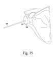
- FIG. 15is an anterior perspective view showing a guide pin inserted in the glenoid of a patient during a surgical procedure to implant the augmented glenoid component of FIGS. 1-3 ;
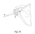
- FIG. 16is a view similar to FIG. 15 showing reamer being used to ream the patient's glenoid;
- FIG. 17is a view similar to FIG. 15 showing a drill being used to drill the anchor hole into the patient's glenoid;
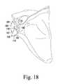
- FIG. 18is a view similar to FIG. 15 showing the rasp guide secured to the patient's glenoid;
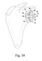
- FIG. 19is a posterior perspective view showing the oscillating rasp of FIGS. 4-6 during rasping the patient's glenoid.
- FIG. 20is a view similar to FIG. 19 showing the patient's glenoid after it has been surgically prepared with the oscillating rasp of FIGS. 4 and 5 .
- Terms representing anatomical referencessuch as anterior, posterior, medial, lateral, superior, inferior, etcetera, may be used throughout this disclosure in reference to both the orthopaedic implants described herein and a patient's natural anatomy. Such terms have well-understood meanings in both the study of anatomy and the field of orthopaedics. Use of such anatomical reference terms in the specification and claims is intended to be consistent with their well-understood meanings unless noted otherwise.
- the augmented glenoid component 10includes a body 22 having a concave surface 26 on one end thereof.
- the concave surface 26 of the body 22provides a smooth bearing surface upon which a natural or prosthetic humeral head articulates.
- a buttress 24extends away from the anterior medial surface 32 of the body 22 opposite the concave surface 26 .
- the posterior medial surface 28 of the buttress 24is substantially flat in the anterior/posterior direction and rounded (i.e., convex) in the superior/inferior direction.
- the anterior medial surface 32is rounded (i.e., convex) in all directions, but may include flat portions to fit the need of a given design.
- a side surface 30extends perpendicularly from the posterior medial surface 28 to the anterior medial surface 32 . Alternatively, the side surface 30 may be angled relative to both surfaces 28 , 32 .
- the augmented glenoid component 10also includes an anchor peg 34 .
- the anchor peg 34extends perpendicularly from the anterior medial surface 32 .
- the anchor peg 34includes a tapered head 36 that functions as a lead-in to facilitate insertion into a hole drilled or otherwise formed in the glenoid surface of the patient's scapula.
- the glenoid component 10also includes a plurality of stabilizing pegs 38 .
- One of the pegs 38extends from the anterior medial surface 32 , with another of the pegs 38 extending from the posterior medial surface 28 of the buttress 24 .
- Another of the three stabilizing pegs 38extends from both the anterior medial surface 32 and the buttress 24 —i.e., it straddles the buttress 24 and the anterior medial surface 32 .
- the stabilizing pegs 38are shorter than the anchor peg 34 .
- some of the stabilizing pegs 38e.g., the one extending from the anterior medial surface 32
- the stabilizing pegs 38are received into a number of corresponding holes drilled or otherwise formed in the glenoid surface of the patient's scapula.
- the augmented glenoid component 10is embodied as a monolithic molded component. That is, the body 22 , the anchor peg 34 , and the stabilizing pegs 38 are integrally molded using a polymer such as polyethylene.
- a polymersuch as polyethylene.
- a suitable polyethyleneis ultrahigh molecular weight polyethylene (UHMWPE).
- UHMWPEultrahigh molecular weight polyethylene
- the augmented glenoid component 10may be made from ceramic, metal, or a composite material. Examples of these materials include alumina, zirconia, and alumina/zirconia composite or composite material.
- the anchor peg 34includes a plurality of radial fins 40 .
- the fins 40are deformable. This allows the anchor peg 34 to fit into an anchor bore drilled in the glenoid surface of the patient's scapula, but resist removal or “pull out” of the anchor peg 34 . Any number or size of radial fins 40 may be included on the anchor peg 34 .
- each of the fins 40is herein described with the same sized outer diameter, it should be appreciated that other configurations are also contemplated for use.
- the fins 40may be provided in a tapered configuration in which the respective outer diameters of the fins 40 gradually increases from the distal end of the anchor peg 34 to the proximal end of the anchor peg 34 (i.e. the ring positioned on the distal end of the anchor peg 34 has a smaller diameter relative to the ring positioned near the proximal end of the anchor peg 34 ).
- the fins 40are configured to slightly deform when the anchor peg 34 is inserted into an anchor hole drilled in the patient's glenoid. This is caused when the fins 40 are advanced into the anchor hole since it is drilled to have a diameter which is slightly larger than the diameter of a shaft of the anchor peg 34 , yet smaller than the outer diameter of the fins 40 thereby causing deformation of the fins 40 upon contact with the sidewalls of the drilled hole as the fins 40 are “forced” into the hole.
- Such deformation of the fins 40secures the augmented glenoid component to the scapula by providing resistance to pull out of the anchor peg 34 from the drilled anchor hole much in the same way that the threads of a screw provide resistance to pull out of the screw from the material into which it is driven.
- bone tissue or other types of tissuewill grow into the spaces between the fins 40 thereby providing further resistance to pull out of the anchor peg 34 from the drilled hole.
- the stabilizing pegs 38prevent rotation or other types of movement of the augmented glenoid component 10 relative to the scapula once the glenoid component 10 has been implanted.
- the distal end of each of the stabilizing pegs 38has a conical tip which functions as a “lead in” to facilitate insertion of the stabilizing pegs 38 into respective stabilizing holes drilled in the glenoid surface of the patient's scapula.
- the stabilizing pegs 38may be arranged in any orientation on the body 22 that fits the needs of a given design of an augmented glenoid component.
- any number of stabilizing pegs 38may be utilized to fit the needs of a given design of an augmented glenoid component. Examples of such variations are shown in commonly-owned U.S. Pat. No. 6,699,289, the entirety of which is hereby incorporated by reference.
- the rasp 50includes an attachment head 52 that fits into the chuck 102 of an oscillating power tool 100 (see FIG. 7 ).
- the oscillating rasp 50also includes a cutting head 58 secured to the distal end 56 of the attachment head 52 .
- the geometry of the cutting head 58corresponds with the geometry of the buttress 24 of the augmented glenoid component 10 when the oscillating rasp 50 is oscillated along a predetermined path in contact with the glenoid of the patient.
- the cutting head 58 of the oscillating rasp 50includes a plurality of cutting teeth 60 .
- the cutting teeth 60 of the oscillating rasp 50abrade or otherwise cut the bone tissue of the scapula thereby gradually creating notch possessing the geometry (i.e., the shape) required to accept the buttress 24 of the augmented glenoid component 10 .
- the cutting teeth 60are herein described as elongated, linear cutting teeth, other embodiments of cutting teeth may be used.
- the cutting teeth 60may be embodied as diamond knurl-type cutting teeth.
- the attachment head 52includes a keying slot 62 and a number of drive holes 64 .
- the hub 102 of the oscillating power tool 100includes a number of features such as detents (not shown) that are received into the keying slot 62 and drive holes 64 to couple the oscillating rasp 50 the oscillating power tool 100 (see FIG. 7 ).
- the attachment head 52is herein shown with a specific exemplary mounting configuration (i.e., the configuration including the keying slot 62 and the drive holes 64 ), other mounting configurations are contemplated for use in the design of the attachment head 52 to allow the rasp 50 to be coupled to specific types of oscillating power tools 100 .
- the attachment head 52may be embodied with a “universal” mounting configuration to allow the same rasp 50 to be coupled to multiple different oscillating power tools 100 .
- the cutting head 58includes a cutting surface 66 that extends posteriorly from the longitudinal axis 68 of the oscillating rasp 50 (see FIG. 6 ).
- the cutting surface 66 of the cutting head 58mimics the shape of the posterior medial surface 28 of the buttress 24 of the augmented glenoid component 10 when the oscillating rasp 50 is oscillated along a predetermined path in contact with the glenoid of the patient. That is, when the oscillating rasp 50 is oscillated along a predetermined path in contact with the glenoid of the patient, the cutting surface 66 produces a rasped surface that is substantially flat in the anterior/posterior direction and rounded (i.e., convex) in the superior/inferior direction.
- the cutting surface 66is defined by the outer surfaces of a plurality of the cutting teeth 60 .
- the cutting surface 66i.e., the outer surfaces of the cutting teeth 60
- the cutting surface 66extends posteriorly away from the longitudinal axis 68 at a non-orthogonal angle.
- the cutting surface 66i.e., the outer surfaces of the cutting teeth 60
- an imaginary line 80extends posteriorly from the longitudinal axis 68 of the oscillating rasp 50 along the outer surface of each of the plurality of cutting teeth 60 (i.e., along the cutting surface 66 ).
- the imaginary line 80intersects the longitudinal axis 68 of the oscillating rasp 50 to define an angle of intersection ( ⁇ ) therebetween.
- the angle of intersection ( ⁇ )is between 30°-90°.
- the angle of intersection ( ⁇ )is between 30°-89° to produce a rounded surface in the superior/inferior direction.
- the angle of intersection ( ⁇ )is approximately 75°.
- the angle of intersection ( ⁇ )is 76.7°.
- the oscillating rasp 50may also be embodied as a tool for preparing the patient's glenoid for implantation of revision component such as a vault-type component.
- revision componentsuch as a vault-type component.
- a revision surgerymay be performed to replace a glenoid component.
- the previously implanted glenoid componentis surgically removed and a replacement glenoid component is implanted in the patient's glenoid.
- the subcondylar platemay be damaged or missing subsequent to revision surgery.
- Revision surgerymay also result in defects, some of which may be fairly large, in the cancellous bone of the glenoid vault of the scapula.
- Vault-filling (i.e., vault-type) revision glenoid componentshave been developed that include a metal backing that extends into (i.e., “fills”) the glenoid vault to replace the lost bone.
- a bearing componentgenerally made of polyethylene (e.g., UHMWPE) or other materials such as ceramics or metals, is then fixed to the implanted metal backing to create the bearing surface upon which the proximal end (e.g., a prosthetic head) of the humeral component articulates.
- a vault-type componentincludes a number of inclined side walls which form a wedge-shaped body.
- the angle of intersection ( ⁇ ) between the imaginary line 80 and the longitudinal axis 68 of the oscillating rasp 50is between 20°-30°.
- the cutting surface 66 of the cutting head 58mimics the shape of the posterior medial surface 28 of the buttress 24 of the augmented glenoid component 10 when the oscillating rasp 50 is oscillated along a predetermined path in contact with the glenoid of the patient.
- the throw of the oscillating tool 100is 8°—i.e., the rasp is advanced through a 4° path in each direction from center.
- the configuration of the oscillating surgical rasp 50allows it to accommodate any number of the different throws created by different oscillating tools 100 .
- the cutting teeth 60 of the rasp's cutting head 58angle toward one another when viewed front-to-back (i.e., in the anterior-to-posterior direction).
- the cutting teeth 60include a number of superior cutting teeth 82 and a number of inferior cutting teeth 84 .
- the inferior cutting teeth 84are positioned inferiorly relative to the superior cutting teeth 82 .
- each of the superior cutting teeth 82are parallel to one another, with each of the inferior cutting teeth 84 likewise being parallel to one another.
- the superior cutting teeth 82 and the inferior cutting teeth 84extend posteriorly away from the longitudinal axis 68 of the oscillating rasp at an angle relative to one another so as to converge toward one another. This is shown illustratively in FIG. 8 where the anterior end 86 of a given superior cutting tooth 82 is spaced apart from the anterior end 88 of a given inferior cutting tooth 84 by a distance that is greater than the distance in which the posterior end 90 of the same superior cutting tooth 82 is spaced apart from the posterior end 92 of the same inferior cutting tooth 84 . In other words, the distance between the posterior ends of a given pair of teeth 82 , 84 is shorter than the distance between the same pair of teeth's anterior ends. Such an angled arrangement allows the cutting teeth 82 , 84 to efficiently expel removed bone tissue during operation of the oscillating rasp 50 .
- the rasp's cutting head 58also has a number of non-cutting surfaces.
- a substantially flat, smooth anterior sidewall 70extends upwardly from the anterior end 72 of the cutting head 58 .
- the anterior sidewall 70is devoid of cutting teeth.
- a posterior sidewall 74extends upwardly from the posterior end 76 of the cutting surface 66 to a backside surface 78 of the cutting head 58 .
- the posterior sidewall 74 and the backside surface 78are devoid of cutting teeth.
- the cutting surface 66 of the oscillating surgical rasp 50has a radius of curvature R 1 .
- the origin of the cutting surface's radius of curvatureis the center of the keying slot 62 . This represents the center of oscillation when the rasp 50 is operated.
- the posterior medial surface 28 of the buttress 24 of the augmented glenoid component 10is rounded (i.e., convex) in the superior/inferior direction.
- the rounded surface of the posterior medial surface 28 of the buttress 24has a radius of curvature R 2 .
- the oscillating rasp 50is embodied such that the radius of curvature R 1 of its cutting surface 66 closely mimics the radius of curvature R 2 of the posterior medial surface 28 of the buttress 24 of the augmented glenoid component 10 .
- the length of the radius of curvature R 1 of the rasp's cutting surface 66is ⁇ 5 mm of the length of the radius of curvature R 2 of the posterior medial surface 28 of the buttress 24 of the augmented glenoid component 10 .
- the length of the radius of curvature R 1 of the rasp's cutting surface 66is ⁇ 3 mm of the length of the radius of curvature R 2 of the posterior medial surface 28 of the buttress 24 of the augmented glenoid component 10 . In an even more specific exemplary embodiment, the length of the radius of curvature R 1 of the rasp's cutting surface 66 is equal to the length of the radius of curvature R 2 of the posterior medial surface 28 of the buttress 24 of the augmented glenoid component 10 .
- both the length of the radius of curvature R 1 of the rasp's cutting surface 66 and the length of the radius of curvature R 2 of the posterior medial surface 28 of the buttress 24 of the augmented glenoid component 10are 32.97 mm.
- the cutting head 58 of the oscillating rasp 50also includes a depth stop 96 .
- the depth stop 96extends in the direction opposite to the cutting surface 66 .
- the depth stop 96extends anteriorly from the longitudinal axis 68 of the oscillating rasp 50 .
- the depth stop 96bottoms out on a rasp guide 110 secured to the reamed surface of the patient's glenoid to ensure the posterior glenoid surface is prepared to the desired depth relative to the anterior glenoid surface.
- the depth stop 96creates a spatial relationship (i.e., a depth) between the surgically-prepared anterior and posterior glenoid surfaces which matches the distance between the posterior medial surface 28 of the glenoid component's buttress 24 and its anterior medial surface 32 .
- a distanceis defined by the height of the side surface 30 that extends perpendicularly from the posterior medial surface 28 of the buttress 24 to the anterior medial surface 32 of the augmented glenoid component 10 (see FIGS. 1-3 ).
- the depth stop 96may be embodied as a number of different structures.
- the depth stop 96may be embodied as one or more tabs, bars, flanges, other similar structures configured to bottom out on the rasp guide 110 secured to the anterior surface of the patient's glenoid to prevent further penetration of the cutting head 58 into the posterior surface of the patient's glenoid.
- the depth stop 96is embodied as a generally oval-shaped bar that has its edge secured to the anterior sidewall 70 of the rasp's cutting head 58 .
- the oscillating surgical rasp 50is embodied as a monolithic component.
- the attachment head 52is integrally formed with the cutting head 58 .
- the oscillating surgical rasp 50may be constructed from a medical-grade metal such as stainless steel, cobalt chrome, or titanium, although other metals or alloys may be used.
- rigid polymerssuch as polyaryetheretherketone (PEEK) may also be used.
- the rasp guide 110for use along with the oscillating rasp 50 in a surgical procedure to implant the augmented glenoid component 10 .
- the rasp guide 110includes a body 122 having a concave guide surface 126 on one end thereof.
- the concave guide surface 126 of the body 122provides a smooth guide surface upon which depth stop 96 bottoms out and thereafter articulates during operation of the oscillating surgical rasp 50 .
- An anchor surface 132is formed in the side of the body 122 opposite the concave surface 126 .
- the anchor surface 132is rounded (i.e., convex) and configured to be secured to the glenoid of the patient.
- the rasp guide 110also includes an anchor peg 134 .
- the anchor peg 134extends perpendicularly from the anchor surface 132 .
- the anchor peg 134includes a tapered head 136 that functions as a lead-in to facilitate insertion into a hole drilled or otherwise formed in the glenoid surface of the patient's scapula.
- the anchor peg 134 of the rasp guide 110shares a common configuration (e.g., length and diameter) with the anchor peg 34 of the augmented glenoid component 10 .
- the rasp guide 110also includes a number of pointed anchoring pins 138 .
- the anchoring pins 138extend perpendicularly away from the anchor surface 132 of the rasp guide 110 .
- the anchoring pins 138may be driven into the glenoid of the patient to stabilize the rasp guide 110 (e.g., prevent it from rotating about the anchor peg 134 ).
- a hole 140extends through the body 122 if the rasp guide 110 .
- a separate anchoring pin(not shown) can be inserted through the hole 140 and driven into the glenoid of the patient to further stabilize the rasp guide 110 .
- the posterior edge 142 of the rasp guide 110defines a vertical boundary between the anterior and posterior portions of the glenoid.
- the rasp guide 110protects the prepared anterior surface and the center hole (i.e., the hole into which the anchor peg 34 of the augmented glenoid component 10 is inserted).
- the cutting head 58is prevented from cutting anteriorly of the edge 142 of the rasp guide 110 thereby creating a wall of bone in the center of the glenoid that serves as the perpendicular step between the anterior and posterior halves of the medial surface of the augmented glenoid component 10 —i.e., a surgically prepared surface that corresponds with the side surface 30 of the augmented glenoid component 10 .
- the guide surface 126 of the rasp guide 110has a radius of curvature R 3 .
- the rounded surface of the posterior medial surface 28 of the buttress 24has a radius of curvature R 2 .
- the cutting guide 11is embodied such that the radius of curvature R 3 of its guide surface 126 closely mimics the radius of curvature R 2 of the posterior medial surface 28 of the buttress 24 of the augmented glenoid component 10 .
- the length of the radius of curvature R 3 of the guide's guide surface 126is ⁇ 5 mm of the length of the radius of curvature R 2 of the posterior medial surface 28 of the buttress 24 of the augmented glenoid component 10 . In a more specific exemplary embodiment, the length of the radius of curvature R 3 of the guide's guide surface 126 is ⁇ 3 mm of the length of the radius of curvature R 2 of the posterior medial surface 28 of the buttress 24 of the augmented glenoid component 10 .
- the length of the radius of curvature R 3 of the guide's guide surface 126is equal to the length of the radius of curvature R 2 of the posterior medial surface 28 of the buttress 24 of the augmented glenoid component 10 .
- both the length of the radius of curvature R 3 of the guide's guide surface 126 and the length of the radius of curvature R 2 of the posterior medial surface 28 of the buttress 24 of the augmented glenoid component 10are 32.97 mm.
- the rasp guide 110is embodied as a monolithic component.
- the body 122is integrally formed with the anchor peg 134 .
- the rasp guide 110may be constructed from a medical-grade metal such as stainless steel, cobalt chrome, or titanium, although other metals or alloys may be used.
- rigid polymerssuch as polyaryetheretherketone (PEEK) may also be used.
- the surgical procedurebegins with preoperative planning in which, amongst other things, a thin cut (1 mm) axial CT scan with the gantry positioned perpendicular to the plane of the glenoid and plane of the scapula is obtained. A single axial slice just below the mid-equator of the glenoid is obtained for measurement of glenoid version. Correction of retroversion may then be individualized to the patient.
- the preoperative planningcomplete, the patient's soft tissue is dissected and retracted in order to allow access to the glenoid. Full (i.e., 360°) exposure of the bony glenoid is typically achieved.
- a guide pin 186is then inserted in the center of the glenoid 184 in an orientation that will allow for the desired amount of retroversion correction. This can be accomplished using one of a number of different pin placement devices.
- the guide pin 186may be scored in locations along its length to allow for controlled breakage to adjust the length of the pin 186 subsequent to being inserted. Specifically, at any point in the procedure, the guide pin 186 can be shortened to a more desirable length by placing a handle just above a score mark and a needle driver just below the same score mark and bending the pin 186 at the score mark. In the illustrative procedure described herein, two to three inches of the pin 186 protrude laterally from the glenoid.
- a sizer pin guide(not shown) may then be placed over the guide pin 186 .
- the sizer pin guideis used determine the optimal size augmented glenoid component for the patient's glenoid.
- a desired size of an augmented glenoid componentcovers as much of the glenoid surface as possible without overhanging the periphery of the bone surface.
- the anterior surface 188 of the patient's glenoid 184is then reamed in a typical manner.
- a spherical reamer 182is used over the guide pin 186 to ream the anterior surface 188 of the glenoid and create an even, concave surface from the superior edge of the glenoid 184 (i.e., 12 o'clock) to the inferior edge of the glenoid 184 (i.e., 6 o'clock).
- This reamed surface 190is the final surgically-prepared surface that contacts the anterior medial surface 32 of the augmented glenoid component 10 when it is implanted.
- the spherical reamer 182 usedis smaller than the superior/inferior dimension of the augmented glenoid component 10 , a small amount of bone on the superior and/or inferior aspects of the anterior glenoid will remain. This remaining bone may be removed with a peripheral reamer (not shown). A hand bun (not shown) may be alternatively used to remove the remaining bone.
- the reamed surface 190 of the patient's anterior glenoid 184is shown in FIG. 17 .
- a depth gauge(not shown) may then be placed over the guide pin 186 .
- the contact and conformity between the back surface of the depth gauge and the prepared anterior glenoid surface 190is the determined. Further preparation of the bone may then be performed if the contact and conformity is not to the surgeon's satisfaction.
- the maximum depth of the posterior glenoid defectis measured by inserting a depth probe (not shown) through the depth gauge.
- a depth probe(not shown) through the depth gauge.
- three holes in the posterior half of the depth gaugeare provided so that three different locations and their respective depths can be evaluated. In most cases the greatest depth of the defect is on the posterior, inferior quadrant of the glenoid.
- Such an evaluationallows for implant selection (i.e., selection of a particularly sized augmented glenoid component 10 ).
- an augmented glenoid component 10 with a 3 mm augmenti.e., a 3 mm thick buttress 24
- the depth measuredis between 3 mm and 5 mm
- an augmented glenoid component 10 with a 5 mm augmentis needed.
- the depth measuredis between 5 mm and 7 mm
- an augmented glenoid component 10 with a 7 mm augmentis needed.
- additional bonemay need to be removed from the anterior surface 188 of the patient's glenoid 184 .
- the amount of additional bone to be removedis equal to the maximum defect minus 7 mm.
- the appropriate size posterior preparation guide(not shown) is then placed over the guide pin 186 so that it firmly and concentrically contacts the prepared anterior glenoid surface 190 .
- the posterior window in the guidedefines the boundaries of the posterior surface 194 of the glenoid 184 to be prepared to accept the buttress 24 of the augmented glenoid component 10 , and it can be used as a template for marking these boundaries with either a sterile pen, saw blade, or a bovie.
- the posterior glenoidis surgically prepared.
- a cannulated center drill 180 of the appropriate length based on the step height of the buttress 24 of the selected augmented glenoid component 10is inserted over the guide pin 186 .
- the drillis then used to prepare (i.e., drill) the glenoid 184 to accept the anchor peg 34 of the augmented glenoid component 10 .
- the drill 180is advanced until it bottoms out on the reamed anterior surface 190 of the glenoid 184 .
- a pin puller or other instrument(not shown) is used to grasp and remove the guide pin 186 .
- the appropriate sized rasp guide 110is then secured to the reamed anterior surface 190 of the glenoid 184 .
- the tapered head 136 of the rasp guide's anchor peg 134is inserted into the center hole 178 drilled in the reamed anterior surface 190 of the glenoid 184 .
- the rasp guide 110may then be tapped with a surgical mallet (not shown) or other instrument to drive the anchoring pins 138 of the rasp guide 110 into the glenoid 184 of the patient to stabilize the rasp guide 110 (e.g., prevent it from rotating about the anchor peg 134 ).
- an additional anchoring pin 176can be inserted through the hole 140 and driven into the glenoid 184 of the patient to further stabilize the rasp guide 110 .
- the posterior edge 142 of the rasp guide 110defines a vertical boundary between the reamed anterior surface 190 and the posterior surface 194 of the glenoid 184 that is to be rasped.
- the rasp guide 110protects the prepared anterior surface 190 and the center hole 178 .
- the rasp guideis centered in the anterior/posterior direction.
- the vertical boundary created by the guide's posterior 142divides the glenoid 184 into two equally sized halves in the anterior/posterior direction.
- the cutting head 58is prevented from cutting anteriorly of the edge 142 of the rasp guide 110 thereby creating a wall of bone in the center of the glenoid 184 that serves as the perpendicular step between the anterior and posterior halves of the medial surface of the augmented glenoid component 10 —i.e., a surgically prepared surface that corresponds with the side surface 30 of the augmented glenoid component 10 .
- An oscillating rasp 50 sized to match the buttress 24 of the selected augmented glenoid component 10is then obtained from a number of differently-sized rasps 50 and used to complete the posterior preparation.
- the attachment head 52 of the selected oscillating rasp 50is then secured within the chuck 102 of the oscillating power tool 100 (see FIG. 7 ). Once chucked, the rasp 50 is advanced into contact with the posterior portion of the glenoid 184 . As shown in FIG. 19 , the surgeon then activates the oscillating power tool 100 and advances the cutting surface 66 of the cutting head 58 into contact with the posterior surface 194 of the glenoid 184 .
- the oscillating motion of the rasp 50abrades the bone and continues to remove bone until the leading surface 94 of the depth stop 96 (see FIGS. 4-7 ) bottoms out on the concave guide surface 126 of the rasp guide 110 .
- the surgeoncontinues to oscillate the rasp 50 with the depth stop 96 riding on the concave guide surface 126 thereby using the rasp guide 110 as a preparation guide. This ensures the posterior glenoid surface 194 is prepared to the desired depth relative to the anterior glenoid surface 190 .
- the depth stop 96creates a spatial relationship (i.e., a depth) between the surgically-prepared anterior surface 190 and the posterior glenoid surface 194 which matches the distance between the posterior medial surface 28 of the glenoid component's buttress 24 and its anterior medial surface 32 .
- a distanceis defined by the height of the side surface 30 that extends perpendicularly from the posterior medial surface 28 of the buttress to the anterior medial surface 32 of the augmented glenoid component 10 (see FIGS. 1-3 ).
- the posterior preparation of the glenoid 184is complete—i.e., the rasped posterior glenoid surface 198 has been completed (see FIG. 20 ).
- a number of differently-sized rasps 50may be used.
- a number of progressively larger-sized rasps 50may be used to produce the desired final size.
- initial raspingmay be performed with a rasp 50 having a relatively small cutting head 58 .
- one or more additional rasps 50 having progressively larger cutting heads 58may be used to perform subsequent rasping to form a larger cavity of the desired final size.
- a bone preparation assessor(not shown), which is sized to mimic the medial surfaces of the selected augmented glenoid component 10 , is then used to determine whether the anterior reaming and posterior rasping of the bony surfaces was sufficient to accommodate the selected augmented glenoid component 10 .
- the bone preparation assessorgenerally makes full and concentric contact with the prepared glenoid surfaces. If high spots on the bone are preventing the bone preparation assessor from seating completely, an impactor, tamp, or other instrument may be used to make the prepared glenoid surfaces more conforming. The fit of the bone preparation assessor may then be assessed again.
- a peripheral drill guide (not shown) specific to the selected augmented glenoid component 10is then inserted into the drilled center hole.
- the holes for the stabilizing pegs 38are then drilled with the assistance of the drill guide.
- An implant trial(not shown) is placed into the prepared glenoid 184 , and its fit is assessed. Full and concentric contact between the medial side of the trial and the prepared surfaces of the bone is generally desired. If this is not the case, some or all of the prior bone preparation steps may be repeated. If the fit is adequate, the trial is removed.
- Finely morselized bone retrieved during the glenoid preparationis used to create a “bone paste.”
- This bone pasteis interposed between the fins 40 of the anchor peg 34 of the augmented glenoid component 10 to facilitate tissue integration.
- Bone cementsuch as PMMA-based bone cement, is placed in the peripheral holes (i.e., the holes for the stabilizing pegs 38 ) of the prepared glenoid 184 and pressurized using a fingertip.
- the augmented glenoid component 10is then inserted, and a glenoid impactor (not shown) is used to seat the component 10 until there is complete contact with the perimeter of the glenoid 184 . Pressure on the implanted component 10 is maintained until the cement has hardened.
- the surgeonmay then rasp the posterior glenoid surface 194 using the surgically-prepared anterior surface 190 as a guide surface. Namely, the surgeon may rasp the posterior glenoid surface 194 with the depth stop 96 riding on the surgically-prepared anterior surface 190 thereby using the reamed anterior glenoid surface 190 as a guide surface.
- the oscillating rasp 50 described hereinmay be used to surgically prepare the bony anatomy for other types of arthroplasty.
- the oscillating rasp 50with or without some modification thereto, may be used in a hip procedure or other type of joint procedure.
- the oscillating rasp 50may be used to prepare the other surfaces of the glenoid, such as the anterior glenoid surface.
- the oscillating rasp 50may also be used in a bone grafting procedure for shaping the glenoid surface.
Landscapes
- Health & Medical Sciences (AREA)
- Surgery (AREA)
- Life Sciences & Earth Sciences (AREA)
- Biomedical Technology (AREA)
- Medical Informatics (AREA)
- Orthopedic Medicine & Surgery (AREA)
- Oral & Maxillofacial Surgery (AREA)
- Engineering & Computer Science (AREA)
- Dentistry (AREA)
- Heart & Thoracic Surgery (AREA)
- Nuclear Medicine, Radiotherapy & Molecular Imaging (AREA)
- Molecular Biology (AREA)
- Animal Behavior & Ethology (AREA)
- General Health & Medical Sciences (AREA)
- Public Health (AREA)
- Veterinary Medicine (AREA)
- Surgical Instruments (AREA)
- Prostheses (AREA)
Abstract
Description
Claims (17)
Priority Applications (2)
| Application Number | Priority Date | Filing Date | Title |
|---|---|---|---|
| US14/809,303US9861376B2 (en) | 2011-01-28 | 2015-07-27 | Oscillating rasp for use in an orthopaedic surgical procedure |
| US15/862,436US10159500B2 (en) | 2011-01-28 | 2018-01-04 | Oscillating rasp for use in an orthopaedic surgical procedure |
Applications Claiming Priority (3)
| Application Number | Priority Date | Filing Date | Title |
|---|---|---|---|
| US13/016,404US8486076B2 (en) | 2011-01-28 | 2011-01-28 | Oscillating rasp for use in an orthopaedic surgical procedure |
| US13/940,540US9089348B2 (en) | 2011-01-28 | 2013-07-12 | Oscillating rasp for use in an orthopaedic surgical procedure |
| US14/809,303US9861376B2 (en) | 2011-01-28 | 2015-07-27 | Oscillating rasp for use in an orthopaedic surgical procedure |
Related Parent Applications (1)
| Application Number | Title | Priority Date | Filing Date |
|---|---|---|---|
| US13/940,540ContinuationUS9089348B2 (en) | 2011-01-28 | 2013-07-12 | Oscillating rasp for use in an orthopaedic surgical procedure |
Related Child Applications (1)
| Application Number | Title | Priority Date | Filing Date |
|---|---|---|---|
| US15/862,436DivisionUS10159500B2 (en) | 2011-01-28 | 2018-01-04 | Oscillating rasp for use in an orthopaedic surgical procedure |
Publications (2)
| Publication Number | Publication Date |
|---|---|
| US20150327873A1 US20150327873A1 (en) | 2015-11-19 |
| US9861376B2true US9861376B2 (en) | 2018-01-09 |
Family
ID=45507572
Family Applications (4)
| Application Number | Title | Priority Date | Filing Date |
|---|---|---|---|
| US13/016,404Active2031-08-23US8486076B2 (en) | 2011-01-28 | 2011-01-28 | Oscillating rasp for use in an orthopaedic surgical procedure |
| US13/940,540Expired - Fee RelatedUS9089348B2 (en) | 2011-01-28 | 2013-07-12 | Oscillating rasp for use in an orthopaedic surgical procedure |
| US14/809,303ActiveUS9861376B2 (en) | 2011-01-28 | 2015-07-27 | Oscillating rasp for use in an orthopaedic surgical procedure |
| US15/862,436ActiveUS10159500B2 (en) | 2011-01-28 | 2018-01-04 | Oscillating rasp for use in an orthopaedic surgical procedure |
Family Applications Before (2)
| Application Number | Title | Priority Date | Filing Date |
|---|---|---|---|
| US13/016,404Active2031-08-23US8486076B2 (en) | 2011-01-28 | 2011-01-28 | Oscillating rasp for use in an orthopaedic surgical procedure |
| US13/940,540Expired - Fee RelatedUS9089348B2 (en) | 2011-01-28 | 2013-07-12 | Oscillating rasp for use in an orthopaedic surgical procedure |
Family Applications After (1)
| Application Number | Title | Priority Date | Filing Date |
|---|---|---|---|
| US15/862,436ActiveUS10159500B2 (en) | 2011-01-28 | 2018-01-04 | Oscillating rasp for use in an orthopaedic surgical procedure |
Country Status (4)
| Country | Link |
|---|---|
| US (4) | US8486076B2 (en) |
| EP (2) | EP2481362B1 (en) |
| JP (1) | JP5868718B2 (en) |
| AU (1) | AU2012200276B2 (en) |
Cited By (21)
| Publication number | Priority date | Publication date | Assignee | Title |
|---|---|---|---|---|
| US20180333263A1 (en)* | 2017-05-19 | 2018-11-22 | Biomet Manufacturing, Llc | Implant assembly tools and methods |
| USD835276S1 (en)* | 2015-09-11 | 2018-12-04 | United Orthopedic Corporation | Keeled glenoid |
| US10159500B2 (en) | 2011-01-28 | 2018-12-25 | DePuy Synthes Products, Inc. | Oscillating rasp for use in an orthopaedic surgical procedure |
| US10349982B2 (en) | 2011-11-01 | 2019-07-16 | Nuvasive Specialized Orthopedics, Inc. | Adjustable magnetic devices and methods of using same |
| US10478232B2 (en) | 2009-04-29 | 2019-11-19 | Nuvasive Specialized Orthopedics, Inc. | Interspinous process device and method |
| US10617453B2 (en) | 2015-10-16 | 2020-04-14 | Nuvasive Specialized Orthopedics, Inc. | Adjustable devices for treating arthritis of the knee |
| US10646262B2 (en) | 2011-02-14 | 2020-05-12 | Nuvasive Specialized Orthopedics, Inc. | System and method for altering rotational alignment of bone sections |
| US10660675B2 (en) | 2010-06-30 | 2020-05-26 | Nuvasive Specialized Orthopedics, Inc. | External adjustment device for distraction device |
| US10729470B2 (en) | 2008-11-10 | 2020-08-04 | Nuvasive Specialized Orthopedics, Inc. | External adjustment device for distraction device |
| US10743794B2 (en) | 2011-10-04 | 2020-08-18 | Nuvasive Specialized Orthopedics, Inc. | Devices and methods for non-invasive implant length sensing |
| US10751094B2 (en) | 2013-10-10 | 2020-08-25 | Nuvasive Specialized Orthopedics, Inc. | Adjustable spinal implant |
| US10835290B2 (en) | 2015-12-10 | 2020-11-17 | Nuvasive Specialized Orthopedics, Inc. | External adjustment device for distraction device |
| US10918425B2 (en) | 2016-01-28 | 2021-02-16 | Nuvasive Specialized Orthopedics, Inc. | System and methods for bone transport |
| US11191579B2 (en) | 2012-10-29 | 2021-12-07 | Nuvasive Specialized Orthopedics, Inc. | Adjustable devices for treating arthritis of the knee |
| US11202707B2 (en) | 2008-03-25 | 2021-12-21 | Nuvasive Specialized Orthopedics, Inc. | Adjustable implant system |
| US11234849B2 (en) | 2006-10-20 | 2022-02-01 | Nuvasive Specialized Orthopedics, Inc. | Adjustable implant and method of use |
| US11246694B2 (en) | 2014-04-28 | 2022-02-15 | Nuvasive Specialized Orthopedics, Inc. | System for informational magnetic feedback in adjustable implants |
| US11357549B2 (en) | 2004-07-02 | 2022-06-14 | Nuvasive Specialized Orthopedics, Inc. | Expandable rod system to treat scoliosis and method of using the same |
| US11439449B2 (en) | 2014-12-26 | 2022-09-13 | Nuvasive Specialized Orthopedics, Inc. | Systems and methods for distraction |
| US11612416B2 (en) | 2015-02-19 | 2023-03-28 | Nuvasive Specialized Orthopedics, Inc. | Systems and methods for vertebral adjustment |
| US11752000B2 (en) | 2020-03-03 | 2023-09-12 | Howmedica Osteonics Corp. | Glenoid implant with additively manufactured fixation posts |
Families Citing this family (43)
| Publication number | Priority date | Publication date | Assignee | Title |
|---|---|---|---|---|
| US20090112262A1 (en) | 2007-10-30 | 2009-04-30 | Scott Pool | Skeletal manipulation system |
| US11241257B2 (en) | 2008-10-13 | 2022-02-08 | Nuvasive Specialized Orthopedics, Inc. | Spinal distraction system |
| US8197490B2 (en) | 2009-02-23 | 2012-06-12 | Ellipse Technologies, Inc. | Non-invasive adjustable distraction system |
| JP5751642B2 (en) | 2009-09-04 | 2015-07-22 | エリプス テクノロジーズ, インク.Ellipse Technologies, Inc. | Bone growth apparatus and method |
| US8556901B2 (en) | 2009-12-31 | 2013-10-15 | DePuy Synthes Products, LLC | Reciprocating rasps for use in an orthopaedic surgical procedure |
| WO2012021378A2 (en) | 2010-08-09 | 2012-02-16 | Ellipse Technologies, Inc. | Maintenance feature in magnetic implant |
| FR2967046A1 (en) | 2010-11-10 | 2012-05-11 | Tornier Sa | ORTHOPEDIC BONE PREPARATION MACHINE, ESPECIALLY GLENOIDIAN PREPARATION |
| JP6166775B2 (en)* | 2012-03-28 | 2017-07-19 | オーソソフト インコーポレイティド | Glenoid implants using patient-specific instruments |
| US20130338714A1 (en) | 2012-06-15 | 2013-12-19 | Arvin Chang | Magnetic implants with improved anatomical compatibility |
| US9044281B2 (en) | 2012-10-18 | 2015-06-02 | Ellipse Technologies, Inc. | Intramedullary implants for replacing lost bone |
| US9179938B2 (en) | 2013-03-08 | 2015-11-10 | Ellipse Technologies, Inc. | Distraction devices and method of assembling the same |
| US9044330B2 (en) | 2013-03-12 | 2015-06-02 | DePuy Synthes Products, Inc. | System and method for implanting a secondary glenoid prosthesis |
| US10226242B2 (en) | 2013-07-31 | 2019-03-12 | Nuvasive Specialized Orthopedics, Inc. | Noninvasively adjustable suture anchors |
| US9801734B1 (en) | 2013-08-09 | 2017-10-31 | Nuvasive, Inc. | Lordotic expandable interbody implant |
| US10117657B2 (en)* | 2014-03-21 | 2018-11-06 | Arthrex, Inc. | Nautilus glenoid reamer |
| US9681960B2 (en) | 2014-05-16 | 2017-06-20 | Howmedica Osteonics Corp. | Guides for fracture system |
| US10575968B2 (en) | 2014-05-16 | 2020-03-03 | Howmedica Osteonics Corp. | Guides for fracture system |
| US10028838B2 (en) | 2014-06-30 | 2018-07-24 | Tornier, Inc. | Augmented glenoid components and devices for implanting the same |
| US11234826B2 (en) | 2014-06-30 | 2022-02-01 | Howmedica Osteonics Corp. | Augmented glenoid components and devices for implanting the same |
| KR102588501B1 (en) | 2014-10-23 | 2023-10-11 | 누베이시브 스페셜라이즈드 오소페딕스, 인크. | Remotely adjustable interactive bone reshaping implant |
| US9955984B2 (en)* | 2015-01-12 | 2018-05-01 | Biomet Manufacturing, Llc | Augmented glenoid and method for preparation |
| WO2017139548A1 (en) | 2016-02-10 | 2017-08-17 | Nuvasive Specialized Orthopedics, Inc. | Systems and methods for controlling multiple surgical variables |
| US11129724B2 (en) | 2016-07-28 | 2021-09-28 | Howmedica Osteonics Corp. | Stemless prosthesis anchor component |
| US10548617B1 (en) | 2017-03-31 | 2020-02-04 | Howmedica Osteonics Corp. | Captured slotted reamer |
| EP3651664A1 (en)* | 2017-07-11 | 2020-05-20 | Tornier, Inc. | Guides and instruments for improving accuracy of glenoid implant placement |
| CA3087066A1 (en) | 2017-12-29 | 2019-07-04 | Tornier, Inc. | Patient specific humeral implant components |
| JP2022519380A (en) | 2019-02-07 | 2022-03-23 | ニューベイシブ スペシャライズド オーソペディックス,インコーポレイテッド | Ultrasonic communication in medical devices |
| US11589901B2 (en) | 2019-02-08 | 2023-02-28 | Nuvasive Specialized Orthopedics, Inc. | External adjustment device |
| AU2020204539B2 (en) | 2019-07-12 | 2024-10-31 | Howmedica Osteonics Corp. | Augmented glenoid design |
| US11426285B2 (en) | 2019-09-05 | 2022-08-30 | Howmedica Osteonics Corp. | Truss glenoid augment |
| US12029440B2 (en)* | 2020-06-04 | 2024-07-09 | Howmedica Osteonics Corp. | Reamer for augmented glenoid implant |
| US12213708B2 (en) | 2020-09-08 | 2025-02-04 | Nuvasive Specialized Orthopedics, Inc. | Remote control module for adjustable implants |
| WO2022103835A1 (en) | 2020-11-10 | 2022-05-19 | Zimmer, Inc. | Bi-spring surgical impact tool |
| EP4284274A1 (en) | 2021-01-29 | 2023-12-06 | Zimmer, Inc. | Orthopedic impactor tool |
| WO2022165215A1 (en) | 2021-01-29 | 2022-08-04 | Zimmer, Inc. | Rotary electric surgical hammer impact tool |
| CA3209081A1 (en) | 2021-02-01 | 2022-08-04 | Zimmer, Inc. | Tri-roll thread electric surgical impact tool |
| US20220265326A1 (en) | 2021-02-23 | 2022-08-25 | Nuvasive Specialized Orthopedics, Inc. | Adjustable implant, system and methods |
| US12004793B2 (en) | 2021-02-26 | 2024-06-11 | Zimmer, Inc. | Bi-Spring surgical hammer impact tools |
| US11737787B1 (en) | 2021-05-27 | 2023-08-29 | Nuvasive, Inc. | Bone elongating devices and methods of use |
| EP4380480A1 (en) | 2021-08-03 | 2024-06-12 | NuVasive Specialized Orthopedics, Inc. | Adjustable implant |
| US12390259B2 (en) | 2022-07-19 | 2025-08-19 | Zimmer, Inc. | Linear electric surgical hammer impact tool |
| USD1068077S1 (en) | 2023-02-08 | 2025-03-25 | Treace Medical Concepts, Inc. | Orthopedic rasp for preparing an intercuneiform joint |
| USD1068078S1 (en) | 2023-02-08 | 2025-03-25 | Treace Medical Concepts, Inc. | Handle for an orthopedic instrument |
Citations (125)
| Publication number | Priority date | Publication date | Assignee | Title |
|---|---|---|---|---|
| US166868A (en)* | 1875-08-17 | Improvement in files | ||
| US472259A (en)* | 1892-04-05 | Shoe float or rasp | ||
| US1032897A (en)* | 1911-03-20 | 1912-07-16 | Loyd B Hamilton | Rasp. |
| US1042728A (en)* | 1910-08-13 | 1912-10-29 | Alexis Vernaz | File. |
| US2698621A (en)* | 1953-07-21 | 1955-01-04 | George S Renard | Surgical instrument |
| US2770037A (en)* | 1953-06-30 | 1956-11-13 | Dentatus Ab | Devices for surgical work |
| US3630204A (en)* | 1970-06-24 | 1971-12-28 | Meyer Fishbein | Blade for bone reamer |
| US3913585A (en)* | 1973-07-26 | 1975-10-21 | Technibiotics | Surgical cutting instrument |
| US4023572A (en)* | 1974-08-06 | 1977-05-17 | Hanfried Weigand | Milling tool for preparing a joint socket in the prosthetic replacement of a joint |
| US4178663A (en)* | 1978-08-14 | 1979-12-18 | Oatey Co. | Hand scraper |
| USRE30794E (en)* | 1980-10-03 | 1981-11-17 | Oatey Co. | Hand scraper |
| US4625725A (en)* | 1983-08-30 | 1986-12-02 | Snowden-Pencer, Inc. | Surgical rasp and method of manufacture |
| US4865605A (en) | 1988-02-02 | 1989-09-12 | Dines David M | Modular shoulder prosthesis |
| US5122142A (en)* | 1990-09-13 | 1992-06-16 | Hall Surgical Division Of Zimmer, Inc. | Irrigating saw blade |
| US5169401A (en) | 1991-12-20 | 1992-12-08 | Zimmer, Inc. | Surgical reamer assembly |
| US5261915A (en)* | 1992-04-16 | 1993-11-16 | Scott M. Durlacher | Femur bone rasp with adjustable handle |
| EP0378002B1 (en) | 1989-01-09 | 1993-12-01 | Minnesota Mining And Manufacturing Company | Bone rasp |
| US5282865A (en) | 1992-06-22 | 1994-02-01 | Osteonics Corp. | Humeral shoulder prosthesis |
| US5306285A (en)* | 1993-04-30 | 1994-04-26 | Komet Medical | Surgical saw blade |
| US5342365A (en)* | 1993-07-19 | 1994-08-30 | Padgett Instruments, Inc. | Surgical rasp |
| US5370704A (en) | 1991-03-07 | 1994-12-06 | Joint Medical Products Corporation | Oblong acetabular cup |
| US5382249A (en)* | 1991-05-30 | 1995-01-17 | Synvasive Technology, Inc. | Adjustable surgical blade |
| US5403318A (en)* | 1993-01-15 | 1995-04-04 | Boehringer Laboratories, Inc. | Apparatus and method for shaping bone |
| US5409491A (en)* | 1993-01-15 | 1995-04-25 | Boehringer Laboratories, Inc. | Apparatus and method for shaping bone |
| US5489310A (en)* | 1994-06-27 | 1996-02-06 | Mikhail; W. E. Michael | Universal glenoid shoulder prosthesis and method for implanting |
| US5540693A (en)* | 1992-02-12 | 1996-07-30 | Sierra Surgical, Inc. | Surgical instrument for cutting hard tissue and method of use |
| US5553476A (en) | 1993-08-18 | 1996-09-10 | Sulzer Medizinaltechnik Ag | Process for the production of outer attachment faces on joint implants |
| US5593448A (en)* | 1995-11-14 | 1997-01-14 | Osteonics Corp. | Glenoid component for shoulder prosthesis and implant method |
| EP0903127A2 (en) | 1997-09-09 | 1999-03-24 | Howmedica Inc. | Anatomic glenoid shoulder prosthesis together with methods and tools for implanting same |
| US5913867A (en) | 1996-12-23 | 1999-06-22 | Smith & Nephew, Inc. | Surgical instrument |
| US5919195A (en)* | 1998-01-20 | 1999-07-06 | Johnson & Johnson Professional, Inc. | Oblong acetabular component instrumentation |
| US6022353A (en) | 1991-05-30 | 2000-02-08 | Synasive Technology, Inc. | Surgical saw blade |
| WO2001034040A1 (en) | 1999-11-10 | 2001-05-17 | Depuy International Limited | Bone resection device |
| US6245074B1 (en) | 1999-09-01 | 2001-06-12 | Bristol-Myers Squibb Co. | Orthopaedic glenoid reamer |
| US6358251B1 (en)* | 2000-03-21 | 2002-03-19 | University Of Washington | Method and apparatus for forming a cavity in soft tissue or bone |
| US6364910B1 (en)* | 2001-07-11 | 2002-04-02 | Biomet, Inc. | Method and apparatus for use of a glenoid component |
| US20020095214A1 (en)* | 2001-01-16 | 2002-07-18 | Hyde Edward R. | Transosseous core approach and instrumentation for joint replacement and repair |
| EP1224912A2 (en) | 2001-01-23 | 2002-07-24 | Depuy Orthopaedics, Inc. | Apparatus for resecting a greater tubercle from a humerus |
| US20020099381A1 (en) | 2001-01-23 | 2002-07-25 | Maroney Brian J. | Method and apparatus for resecting a greater tubercle from a humerus of a patient during performance of a shoulder replacement procedure |
| US20020099445A1 (en) | 2001-01-23 | 2002-07-25 | Maroney Brian J. | Method and apparatus for performing a shoulder replacement procedure in the treatment of cuff tear arthropathy |
| US6436101B1 (en)* | 1999-10-13 | 2002-08-20 | James S. Hamada | Rasp for use in spine surgery |
| US20020116023A1 (en)* | 1991-05-30 | 2002-08-22 | Fletcher Henry Hasbrouck | Surgical saw blade |
| US20030014067A1 (en)* | 2001-06-25 | 2003-01-16 | Michael Kullmer | Surgical saw blade |
| US6663636B1 (en)* | 2002-03-12 | 2003-12-16 | United Orthopedic Corporation | Femur rasp fastener |
| US6699289B2 (en)* | 2001-12-31 | 2004-03-02 | Depuy Orthopaedics, Inc. | Augmented glenoid component having an interrupted surface and associated method for securing the augmented glenoid component to a glenoid surface of a scapula |
| EP1402853A2 (en) | 2002-09-27 | 2004-03-31 | Depuy Products, Inc. | Concave resurfacing glenoid prosthesis |
| US6746451B2 (en)* | 2001-06-01 | 2004-06-08 | Lance M. Middleton | Tissue cavitation device and method |
| US20040243134A1 (en) | 2003-05-30 | 2004-12-02 | Walker Peter Stanley | Bone shaping device for knee replacement |
| US20050015153A1 (en)* | 2002-05-24 | 2005-01-20 | Medicine Lodge, Inc. | Implants and related methods and apparatus for securing an implant on an articulating surface of an orthopedic joint |
| US20050043805A1 (en)* | 2003-08-11 | 2005-02-24 | Chudik Steven C. | Devices and methods used for shoulder replacement |
| US6911047B2 (en)* | 2000-03-17 | 2005-06-28 | Depuy Orthopaedics, Inc. | Apparatus and method for securing a cementless glenoid component to a glenoid surface of a scapula |
| EP1550419A2 (en) | 2003-12-30 | 2005-07-06 | Zimmer Technology, Inc. | Tethered implant systems with fastener for mounting on an articulation surface of an orthopedic joint |
| US20050148843A1 (en)* | 2003-12-30 | 2005-07-07 | Roose Jeffrey R. | System and method of designing and manufacturing customized instrumentation for accurate implantation of prosthesis by utilizing computed tomography data |
| US20050234463A1 (en) | 2004-01-05 | 2005-10-20 | Hershberger Troy W | Method and instrumentation for performing minimally invasive hip arthroplasty |
| US20050288676A1 (en)* | 2004-06-29 | 2005-12-29 | Barry Schnieders | Minimally invasive bone broach |
| US20060009854A1 (en)* | 2004-07-09 | 2006-01-12 | Medicinelodge, Inc. | Guide templates for surgical implants and related methods |
| US20060009776A1 (en)* | 2004-07-09 | 2006-01-12 | Medicinelodge, Inc. | Modular guide systems and related rasps and methods for resecting a joint articulation surface |
| US20060058804A1 (en)* | 2002-10-10 | 2006-03-16 | Medical Vision Research & Development Ab | Medical indication device and identification method |
| EP1639949A1 (en) | 2004-09-27 | 2006-03-29 | DePuy Products, Inc. | Instrument for preparing an implant support surface |
| US20060069444A1 (en)* | 2004-09-27 | 2006-03-30 | Deffenbaugh Daren L | Glenoid augment and associated method |
| US20060079963A1 (en)* | 2004-10-07 | 2006-04-13 | Regan Hansen | Semiconstrained shoulder prosthetic for treatment of rotator cuff arthropathy |
| US20060142774A1 (en)* | 2003-01-15 | 2006-06-29 | Biomet Manufacturing Corp. | Instrumentation for knee resection |
| WO2006078864A1 (en)* | 2004-07-28 | 2006-07-27 | Medicinelodge, Inc. | Trochlear groove implants and related methods and instruments |
| US20060195194A1 (en)* | 2005-02-25 | 2006-08-31 | Gunther Stephen B | Shoulder implant for glenoid replacement and methods of use thereof |
| US7108698B2 (en)* | 2004-01-13 | 2006-09-19 | Zimmer Spine, Inc. | Combined distractor and retractor instrument and methods |
| US20060229627A1 (en)* | 2004-10-29 | 2006-10-12 | Hunt Margaret M | Variable angle spinal surgery instrument |
| WO2006136955A1 (en) | 2005-06-03 | 2006-12-28 | Depuy Ireland Limited | Instrument for use in a joint replacement procedure |
| US7160306B2 (en)* | 2001-12-06 | 2007-01-09 | Pentax Corporation | Surgical instruments and a set of surgical instruments for use in treatment of vertebral bodies |
| US20070038302A1 (en)* | 2005-08-15 | 2007-02-15 | Biomet Manufacturing Corp. | Method and apparatus for the preparation of an inlaid glenoid |
| EP1764046A2 (en) | 2005-09-19 | 2007-03-21 | Finsbury (Development) Limited | surgical shaping tool |
| US20070092841A1 (en) | 2005-10-25 | 2007-04-26 | Miyoko Kawashima | Exposure method |
| US7220264B1 (en) | 2003-03-12 | 2007-05-22 | Biomet Manufacturing Corp. | Minimally invasive reamer |
| US20070198002A1 (en) | 2006-02-21 | 2007-08-23 | Cook Incorporated | Implant retrieval assembly and method for retrieving an implant |
| US20070219638A1 (en)* | 2005-10-24 | 2007-09-20 | Benoist Girard Sas | Prosthetic glenoid component |
| US20070219637A1 (en)* | 2006-03-20 | 2007-09-20 | Berelsman Brian K | Modular center pegged glenoid |
| US20070233131A1 (en) | 2006-02-28 | 2007-10-04 | Vermillion Technologies, Llc | Apparatus and method of creating an intervertebral cavity with a vibrating cutter |
| US20070293868A1 (en) | 2004-10-19 | 2007-12-20 | Daniel Delfosse | Ligament-Tentioning Device, Section Template and Osteotomy Method |
| US20080003066A1 (en)* | 2006-06-29 | 2008-01-03 | Arne Haugaard | Convex rasp |
| WO2008005941A2 (en) | 2006-06-30 | 2008-01-10 | Hodge Biomotion Technologies, Llc | Precision acetabular machining system and resurfacing acetabular implant |
| US7326215B2 (en)* | 2002-10-30 | 2008-02-05 | Symmetry Medical, Inc. | Curved surgical tool driver |
| US7371240B2 (en)* | 2000-03-10 | 2008-05-13 | Smith & Nephew, Inc. | Method of arthroplasty on a knee joint and apparatus for use in same |
| US20080147075A1 (en) | 2000-01-14 | 2008-06-19 | Peter M Bonutti | Minimally Invasive Surgical Systems and Methods |
| US20080147070A1 (en)* | 2006-12-13 | 2008-06-19 | Hassler Michel | Reamer for surgical use |
| US20080183297A1 (en)* | 2007-01-30 | 2008-07-31 | Tornier | Method and apparatus for fitting a shoulder prosthesis |
| US20080275453A1 (en) | 2004-06-24 | 2008-11-06 | T.A.G. Medical Products A Limited Partnership | Method and Apparatus for Repairing Separations in the Capsular Labrum Structure |
| US7473254B2 (en)* | 2002-05-10 | 2009-01-06 | Precimed S.A. | Pivoting bone reamer for minimally invasive joint surgery |
| US20090093815A1 (en) | 1991-05-30 | 2009-04-09 | Synvasive Technology, Inc. | Surgical saw blade having at least one pair of opposed teeth shaped as right triangles |
| US20090163921A1 (en)* | 2007-12-20 | 2009-06-25 | Andre Lechot | Disposable acetabular reamer from flat stock |
| US7572259B2 (en) | 2002-09-16 | 2009-08-11 | Greatbatch Ltd. | Inset acetabular reamer coupling |
| WO2009111639A1 (en) | 2008-03-05 | 2009-09-11 | Conformis, Inc. | Patient selectable joint arthroplasty devices and surgical tools |
| US20090270993A1 (en)* | 2008-04-28 | 2009-10-29 | Robin Maisonneuve | Orientation feature on eccentric glenosphere |
| US7621915B2 (en) | 2003-02-10 | 2009-11-24 | Smith & Nephew, Inc. | Acetabular reamer |
| US20090312779A1 (en)* | 2008-06-11 | 2009-12-17 | Medtronic Ps Medical, Inc. | Surgical Cutting Instrument With Near-Perimeter Interlocking Coupling Arrangement |
| US7670343B2 (en)* | 2006-06-14 | 2010-03-02 | Biomet Manufacturing Corp. | Method and apparatus for reaming an acetabulum |
| WO2010033473A2 (en) | 2008-09-18 | 2010-03-25 | Smith & Nephew, Inc. | Apparatus and method for addressing femoral acetabular impingement |
| US7744616B2 (en)* | 2005-10-15 | 2010-06-29 | Stryker Ireland, Ltd. | Surgical sagittal saw blade with angled teeth and chip catchment and reciprocating saw blade with broached teeth |
| US20100191246A1 (en)* | 2009-01-29 | 2010-07-29 | Zimmer, Gmbh | Tool and method for implanting acetabular cup with external screw retention features |
| US20100241235A1 (en)* | 2009-03-20 | 2010-09-23 | Depuy Products, Inc. | Glenoid Component for Use in Shoulder Arthroplasty and Associated Method of Implanting Same |
| US20100249938A1 (en)* | 2005-02-25 | 2010-09-30 | Gunther Stephen B | Methods and devices for less invasive glenoid replacement |
| US20100268238A1 (en) | 2009-04-17 | 2010-10-21 | Arthrosurface Incorporated | Glenoid Resurfacing System and Method |
| US20100298834A1 (en)* | 2007-11-27 | 2010-11-25 | Hildebrandt Bernhardt | Device and apparatus for performing an endoprosthesis implantation |
| WO2011012317A1 (en) | 2009-07-31 | 2011-02-03 | Zimmer Gmbh | Glenoid alignment tool |
| US20110028977A1 (en)* | 2009-07-31 | 2011-02-03 | Zimmer, Gmbh | Orthopaedic reamer |
| US7909828B2 (en) | 2003-01-16 | 2011-03-22 | Greatbatch Medical S.A. | Contoured reamer teeth and method of manufacture |
| US7955337B2 (en)* | 2002-06-29 | 2011-06-07 | Hee-Young Lee | Facial bone contouring device using hollowed rasp provided with non-plugging holes formed through cutting plane |
| US20110213428A1 (en)* | 2003-11-25 | 2011-09-01 | Conformis, Inc. | Patient Selectable Joint Arthroplasty Devices and Surgical Tools |
| US20110213372A1 (en)* | 2009-12-31 | 2011-09-01 | Keefer Ryan C | Reciprocating rasps for use in an orthopaedic surgical procedure |
| US20110213371A1 (en)* | 2009-12-31 | 2011-09-01 | Anthony Sarah M | Reciprocating rasps for use in an orthopaedic surgical procedure |
| US8052689B2 (en) | 2006-12-30 | 2011-11-08 | Greatbatch Medical S.A. | Cut-off acetabular reamer |
| US8133234B2 (en)* | 2006-02-27 | 2012-03-13 | Biomet Manufacturing Corp. | Patient specific acetabular guide and method |
| US20120109226A1 (en)* | 2010-10-29 | 2012-05-03 | The Cleveland Clinic Foundation | System and method for assisting with arrangement of a stock instrument with respect to a patient tissue |
| US20120143267A1 (en)* | 2010-10-29 | 2012-06-07 | The Cleveland Clinic Foundation | System and method for association of a guiding aid with a patient tissue |
| US20120197258A1 (en)* | 2011-01-28 | 2012-08-02 | Chavarria Jason M | Osscilating rasp for use in an orthopaedic surgical procedure |
| US8241289B2 (en)* | 2008-04-28 | 2012-08-14 | Depuy (Ireland) | Manual glenoid reamer |
| US8246621B2 (en)* | 2008-04-28 | 2012-08-21 | Depuy (Ireland) | Reamer guide for revision procedure |
| US20120226283A1 (en)* | 2006-02-27 | 2012-09-06 | Biomet Manufacturing Corp. | Patient-specific acetabular guides and associated instruments |
| US20120239051A1 (en)* | 2011-03-18 | 2012-09-20 | Depuy Products, Inc. | Device and Method for Retroversion Correction for Shoulder Arthroplasty |
| US20120239156A1 (en)* | 2011-03-18 | 2012-09-20 | Depuy Products, Inc. | Revision glenoid device and method |
| US8277452B2 (en)* | 2002-12-12 | 2012-10-02 | Depuy International Limited | Bone resection device |
| US20130072940A1 (en)* | 2010-03-24 | 2013-03-21 | Andrew Joseph Stanley Dawood | Position of hip joint prostheses |
| US8425614B2 (en)* | 2006-03-20 | 2013-04-23 | Biomet Manufacturing Corp. | Modular center pegged glenoid |
| US20130245631A1 (en)* | 2010-08-13 | 2013-09-19 | Smith & Nephew, Inc. | Surgical guides |
| US8603180B2 (en)* | 2006-02-27 | 2013-12-10 | Biomet Manufacturing, Llc | Patient-specific acetabular alignment guides |
| US20130345817A1 (en)* | 2003-03-31 | 2013-12-26 | Jack F. Long | Extended articulation orthopaedic implant |
| US20140012266A1 (en)* | 2010-08-12 | 2014-01-09 | Smith & Nephew, Inc. | Methods and devices for installing standard and reverse shoulder implants |
Family Cites Families (3)
| Publication number | Priority date | Publication date | Assignee | Title |
|---|---|---|---|---|
| US5342635A (en) | 1993-05-12 | 1994-08-30 | General Mills, Inc. | Puffed edible foams and high intensity microwave method of preparation |
| US20080038557A1 (en) | 2006-08-08 | 2008-02-14 | The Procter & Gamble Company | Process for making collapsible water-containing capsules |
| FR2967046A1 (en)* | 2010-11-10 | 2012-05-11 | Tornier Sa | ORTHOPEDIC BONE PREPARATION MACHINE, ESPECIALLY GLENOIDIAN PREPARATION |
- 2011
- 2011-01-28USUS13/016,404patent/US8486076B2/enactiveActive
- 2012
- 2012-01-17AUAU2012200276Apatent/AU2012200276B2/ennot_activeCeased
- 2012-01-19EPEP12151782.5Apatent/EP2481362B1/ennot_activeNot-in-force
- 2012-01-19EPEP16160492.1Apatent/EP3047808B1/ennot_activeNot-in-force
- 2012-01-27JPJP2012015026Apatent/JP5868718B2/ennot_activeExpired - Fee Related
- 2013
- 2013-07-12USUS13/940,540patent/US9089348B2/ennot_activeExpired - Fee Related
- 2015
- 2015-07-27USUS14/809,303patent/US9861376B2/enactiveActive
- 2018
- 2018-01-04USUS15/862,436patent/US10159500B2/enactiveActive
Patent Citations (172)
| Publication number | Priority date | Publication date | Assignee | Title |
|---|---|---|---|---|
| US166868A (en)* | 1875-08-17 | Improvement in files | ||
| US472259A (en)* | 1892-04-05 | Shoe float or rasp | ||
| US1042728A (en)* | 1910-08-13 | 1912-10-29 | Alexis Vernaz | File. |
| US1032897A (en)* | 1911-03-20 | 1912-07-16 | Loyd B Hamilton | Rasp. |
| US2770037A (en)* | 1953-06-30 | 1956-11-13 | Dentatus Ab | Devices for surgical work |
| US2698621A (en)* | 1953-07-21 | 1955-01-04 | George S Renard | Surgical instrument |
| US3630204A (en)* | 1970-06-24 | 1971-12-28 | Meyer Fishbein | Blade for bone reamer |
| US3913585A (en)* | 1973-07-26 | 1975-10-21 | Technibiotics | Surgical cutting instrument |
| US4023572A (en)* | 1974-08-06 | 1977-05-17 | Hanfried Weigand | Milling tool for preparing a joint socket in the prosthetic replacement of a joint |
| US4178663A (en)* | 1978-08-14 | 1979-12-18 | Oatey Co. | Hand scraper |
| USRE30794E (en)* | 1980-10-03 | 1981-11-17 | Oatey Co. | Hand scraper |
| US4625725A (en)* | 1983-08-30 | 1986-12-02 | Snowden-Pencer, Inc. | Surgical rasp and method of manufacture |
| US4865605A (en) | 1988-02-02 | 1989-09-12 | Dines David M | Modular shoulder prosthesis |
| EP0378002B1 (en) | 1989-01-09 | 1993-12-01 | Minnesota Mining And Manufacturing Company | Bone rasp |
| US5122142A (en)* | 1990-09-13 | 1992-06-16 | Hall Surgical Division Of Zimmer, Inc. | Irrigating saw blade |
| US5370704A (en) | 1991-03-07 | 1994-12-06 | Joint Medical Products Corporation | Oblong acetabular cup |
| US5382249A (en)* | 1991-05-30 | 1995-01-17 | Synvasive Technology, Inc. | Adjustable surgical blade |
| US20020116023A1 (en)* | 1991-05-30 | 2002-08-22 | Fletcher Henry Hasbrouck | Surgical saw blade |
| US7901424B2 (en)* | 1991-05-30 | 2011-03-08 | Synvasive Technology, Inc. | Surgical saw blade having at least one pair of opposed teeth shaped as right triangles |
| US20090093815A1 (en) | 1991-05-30 | 2009-04-09 | Synvasive Technology, Inc. | Surgical saw blade having at least one pair of opposed teeth shaped as right triangles |
| US7527628B2 (en)* | 1991-05-30 | 2009-05-05 | Synvasive Technology, Inc. | Surgical saw blade having at least one pair of opposed teeth shaped as right triangles |
| US6723101B2 (en) | 1991-05-30 | 2004-04-20 | Synvasive Technology, Inc. | Method of surgically cutting a bone using a surgical saw blade |
| US6022353A (en) | 1991-05-30 | 2000-02-08 | Synasive Technology, Inc. | Surgical saw blade |
| US5169401A (en) | 1991-12-20 | 1992-12-08 | Zimmer, Inc. | Surgical reamer assembly |
| US5540693A (en)* | 1992-02-12 | 1996-07-30 | Sierra Surgical, Inc. | Surgical instrument for cutting hard tissue and method of use |
| US5261915A (en)* | 1992-04-16 | 1993-11-16 | Scott M. Durlacher | Femur bone rasp with adjustable handle |
| US5282865A (en) | 1992-06-22 | 1994-02-01 | Osteonics Corp. | Humeral shoulder prosthesis |
| US5403318A (en)* | 1993-01-15 | 1995-04-04 | Boehringer Laboratories, Inc. | Apparatus and method for shaping bone |
| US5409491A (en)* | 1993-01-15 | 1995-04-25 | Boehringer Laboratories, Inc. | Apparatus and method for shaping bone |
| US5306285A (en)* | 1993-04-30 | 1994-04-26 | Komet Medical | Surgical saw blade |
| US5342365A (en)* | 1993-07-19 | 1994-08-30 | Padgett Instruments, Inc. | Surgical rasp |
| US5553476A (en) | 1993-08-18 | 1996-09-10 | Sulzer Medizinaltechnik Ag | Process for the production of outer attachment faces on joint implants |
| US6503253B1 (en) | 1993-11-16 | 2003-01-07 | Synvasive Technology, Inc. | Surgical saw blade |
| US5489310A (en)* | 1994-06-27 | 1996-02-06 | Mikhail; W. E. Michael | Universal glenoid shoulder prosthesis and method for implanting |
| US5593448A (en)* | 1995-11-14 | 1997-01-14 | Osteonics Corp. | Glenoid component for shoulder prosthesis and implant method |
| US5913867A (en) | 1996-12-23 | 1999-06-22 | Smith & Nephew, Inc. | Surgical instrument |
| US6673115B2 (en)* | 1997-09-09 | 2004-01-06 | Stryker Technologies Corporation | Anatomic glenoid shoulder prosthesis together with methods and tools for implanting same |
| EP0903127A2 (en) | 1997-09-09 | 1999-03-24 | Howmedica Inc. | Anatomic glenoid shoulder prosthesis together with methods and tools for implanting same |
| US6379386B1 (en)* | 1997-09-09 | 2002-04-30 | Stryker Technologies Corporation | Anatomic glenoid shoulder prosthesis together with methods and tools for implanting same |
| US5919195A (en)* | 1998-01-20 | 1999-07-06 | Johnson & Johnson Professional, Inc. | Oblong acetabular component instrumentation |
| US6245074B1 (en) | 1999-09-01 | 2001-06-12 | Bristol-Myers Squibb Co. | Orthopaedic glenoid reamer |
| US6436101B1 (en)* | 1999-10-13 | 2002-08-20 | James S. Hamada | Rasp for use in spine surgery |
| US6884246B1 (en)* | 1999-11-10 | 2005-04-26 | Depuy International Limited | Bone resection device |
| WO2001034040A1 (en) | 1999-11-10 | 2001-05-17 | Depuy International Limited | Bone resection device |
| US20080147075A1 (en) | 2000-01-14 | 2008-06-19 | Peter M Bonutti | Minimally Invasive Surgical Systems and Methods |
| US7371240B2 (en)* | 2000-03-10 | 2008-05-13 | Smith & Nephew, Inc. | Method of arthroplasty on a knee joint and apparatus for use in same |
| US20050209700A1 (en)* | 2000-03-17 | 2005-09-22 | Rockwood Charles A Jr | Method for securing a glenoid component to a scapula |
| US6911047B2 (en)* | 2000-03-17 | 2005-06-28 | Depuy Orthopaedics, Inc. | Apparatus and method for securing a cementless glenoid component to a glenoid surface of a scapula |
| US7160328B2 (en)* | 2000-03-17 | 2007-01-09 | Deputy Products, Inc. | Method for securing a glenoid component to a scapula |
| US6358251B1 (en)* | 2000-03-21 | 2002-03-19 | University Of Washington | Method and apparatus for forming a cavity in soft tissue or bone |
| US6783548B2 (en)* | 2001-01-16 | 2004-08-31 | Edward R. Hyde, Jr. | Modular joint prostheses |
| US20060142865A1 (en)* | 2001-01-16 | 2006-06-29 | Hyde Edward R Jr | Transosseous core approach and instrumentation for joint replacement and repair |
| US6589281B2 (en)* | 2001-01-16 | 2003-07-08 | Edward R. Hyde, Jr. | Transosseous core approach and instrumentation for joint replacement and repair |
| US20020095214A1 (en)* | 2001-01-16 | 2002-07-18 | Hyde Edward R. | Transosseous core approach and instrumentation for joint replacement and repair |
| US20020138148A1 (en)* | 2001-01-16 | 2002-09-26 | Hyde Edward R. | Transosseous core approach and instrumentation for joint replacement and repair |
| US7611516B2 (en) | 2001-01-23 | 2009-11-03 | Depuy Products, Inc. | Bone resection apparatus |
| US6780190B2 (en) | 2001-01-23 | 2004-08-24 | Depuy Orthopaedics, Inc. | Method and apparatus for resecting a greater tubercle from a humerus of a patient during performance of a shoulder replacement procedure |
| US20020099445A1 (en) | 2001-01-23 | 2002-07-25 | Maroney Brian J. | Method and apparatus for performing a shoulder replacement procedure in the treatment of cuff tear arthropathy |
| US20050021038A1 (en) | 2001-01-23 | 2005-01-27 | Maroney Brian J. | Bone resection apparatus |
| US20020099381A1 (en) | 2001-01-23 | 2002-07-25 | Maroney Brian J. | Method and apparatus for resecting a greater tubercle from a humerus of a patient during performance of a shoulder replacement procedure |
| EP1224912A2 (en) | 2001-01-23 | 2002-07-24 | Depuy Orthopaedics, Inc. | Apparatus for resecting a greater tubercle from a humerus |
| US20040034431A1 (en) | 2001-01-23 | 2004-02-19 | Maroney Brian J. | Method and apparatus for performing a shoulder replacement procedure in the treatment of cuff tear arthropathy |
| US6746451B2 (en)* | 2001-06-01 | 2004-06-08 | Lance M. Middleton | Tissue cavitation device and method |
| US20030014067A1 (en)* | 2001-06-25 | 2003-01-16 | Michael Kullmer | Surgical saw blade |
| US6364910B1 (en)* | 2001-07-11 | 2002-04-02 | Biomet, Inc. | Method and apparatus for use of a glenoid component |
| US7160306B2 (en)* | 2001-12-06 | 2007-01-09 | Pentax Corporation | Surgical instruments and a set of surgical instruments for use in treatment of vertebral bodies |
| US6699289B2 (en)* | 2001-12-31 | 2004-03-02 | Depuy Orthopaedics, Inc. | Augmented glenoid component having an interrupted surface and associated method for securing the augmented glenoid component to a glenoid surface of a scapula |
| US6663636B1 (en)* | 2002-03-12 | 2003-12-16 | United Orthopedic Corporation | Femur rasp fastener |
| US7473254B2 (en)* | 2002-05-10 | 2009-01-06 | Precimed S.A. | Pivoting bone reamer for minimally invasive joint surgery |
| US20050015153A1 (en)* | 2002-05-24 | 2005-01-20 | Medicine Lodge, Inc. | Implants and related methods and apparatus for securing an implant on an articulating surface of an orthopedic joint |
| US7955337B2 (en)* | 2002-06-29 | 2011-06-07 | Hee-Young Lee | Facial bone contouring device using hollowed rasp provided with non-plugging holes formed through cutting plane |
| US7572259B2 (en) | 2002-09-16 | 2009-08-11 | Greatbatch Ltd. | Inset acetabular reamer coupling |
| EP1402853A2 (en) | 2002-09-27 | 2004-03-31 | Depuy Products, Inc. | Concave resurfacing glenoid prosthesis |
| US7329284B2 (en) | 2002-09-27 | 2008-02-12 | Depuy Products, Inc. | Concave resurfacing prosthesis |
| US20060058804A1 (en)* | 2002-10-10 | 2006-03-16 | Medical Vision Research & Development Ab | Medical indication device and identification method |
| US7326215B2 (en)* | 2002-10-30 | 2008-02-05 | Symmetry Medical, Inc. | Curved surgical tool driver |
| US8277452B2 (en)* | 2002-12-12 | 2012-10-02 | Depuy International Limited | Bone resection device |
| US20060142774A1 (en)* | 2003-01-15 | 2006-06-29 | Biomet Manufacturing Corp. | Instrumentation for knee resection |
| US7909828B2 (en) | 2003-01-16 | 2011-03-22 | Greatbatch Medical S.A. | Contoured reamer teeth and method of manufacture |
| US7621915B2 (en) | 2003-02-10 | 2009-11-24 | Smith & Nephew, Inc. | Acetabular reamer |
| US7220264B1 (en) | 2003-03-12 | 2007-05-22 | Biomet Manufacturing Corp. | Minimally invasive reamer |
| US20130345817A1 (en)* | 2003-03-31 | 2013-12-26 | Jack F. Long | Extended articulation orthopaedic implant |
| US20050192583A1 (en) | 2003-05-30 | 2005-09-01 | Walker Peter S. | Bone shaping device for knee replacement |
| US20040243134A1 (en) | 2003-05-30 | 2004-12-02 | Walker Peter Stanley | Bone shaping device for knee replacement |
| US20050192584A1 (en) | 2003-05-30 | 2005-09-01 | Walker Peter S. | Bone shaping device for knee replacement |
| WO2004108012A2 (en) | 2003-05-30 | 2004-12-16 | Walker Peter S | Bone shaping device for knee replacement |
| US20070016304A1 (en)* | 2003-08-11 | 2007-01-18 | Chudik Steven C | Glenoid implant for minimally invasive shoulder replacement surgery |
| US20050043805A1 (en)* | 2003-08-11 | 2005-02-24 | Chudik Steven C. | Devices and methods used for shoulder replacement |
| US20110213430A1 (en)* | 2003-11-25 | 2011-09-01 | Conformis, Inc. | Patient Selectable Joint Arthroplasty Devices and Surgical Tools |
| US20110213429A1 (en)* | 2003-11-25 | 2011-09-01 | Conformis, Inc. | Patient Selectable Joint Arthroplasty Devices and Surgical Tools |
| US20110213428A1 (en)* | 2003-11-25 | 2011-09-01 | Conformis, Inc. | Patient Selectable Joint Arthroplasty Devices and Surgical Tools |
| US20110213431A1 (en)* | 2003-11-25 | 2011-09-01 | Conformis, Inc. | Patient Selectable Joint Arthroplasty Devices and Surgical Tools |
| US20110213427A1 (en)* | 2003-11-25 | 2011-09-01 | Conformis, Inc. | Patient Selectable Joint Arthroplasty Devices and Surgical Tools |
| US7867236B2 (en)* | 2003-12-30 | 2011-01-11 | Zimmer, Inc. | Instruments and methods for preparing a joint articulation surface for an implant |
| US20050148843A1 (en)* | 2003-12-30 | 2005-07-07 | Roose Jeffrey R. | System and method of designing and manufacturing customized instrumentation for accurate implantation of prosthesis by utilizing computed tomography data |
| EP1550419A2 (en) | 2003-12-30 | 2005-07-06 | Zimmer Technology, Inc. | Tethered implant systems with fastener for mounting on an articulation surface of an orthopedic joint |
| US20060009774A1 (en)* | 2003-12-30 | 2006-01-12 | Medicinelodge Inc. | Methods for mounting and using tethered joint bearing implants |
| US20050234463A1 (en) | 2004-01-05 | 2005-10-20 | Hershberger Troy W | Method and instrumentation for performing minimally invasive hip arthroplasty |
| US7108698B2 (en)* | 2004-01-13 | 2006-09-19 | Zimmer Spine, Inc. | Combined distractor and retractor instrument and methods |
| US20080275453A1 (en) | 2004-06-24 | 2008-11-06 | T.A.G. Medical Products A Limited Partnership | Method and Apparatus for Repairing Separations in the Capsular Labrum Structure |
| US7632273B2 (en)* | 2004-06-29 | 2009-12-15 | Depuy Products, Inc. | Minimally invasive bone broach |
| US20050288676A1 (en)* | 2004-06-29 | 2005-12-29 | Barry Schnieders | Minimally invasive bone broach |
| US20060009776A1 (en)* | 2004-07-09 | 2006-01-12 | Medicinelodge, Inc. | Modular guide systems and related rasps and methods for resecting a joint articulation surface |
| US20060009854A1 (en)* | 2004-07-09 | 2006-01-12 | Medicinelodge, Inc. | Guide templates for surgical implants and related methods |
| US7806898B2 (en)* | 2004-07-09 | 2010-10-05 | Zimmer, Inc. | Modular guide systems and related rasps and methods for resecting a joint articulation surface |
| WO2006078864A1 (en)* | 2004-07-28 | 2006-07-27 | Medicinelodge, Inc. | Trochlear groove implants and related methods and instruments |
| US20060069444A1 (en)* | 2004-09-27 | 2006-03-30 | Deffenbaugh Daren L | Glenoid augment and associated method |
| US20060074430A1 (en) | 2004-09-27 | 2006-04-06 | Deffenbaugh Daren L | Instrument for preparing an implant support surface and associated method |
| EP1639949A1 (en) | 2004-09-27 | 2006-03-29 | DePuy Products, Inc. | Instrument for preparing an implant support surface |
| US7927335B2 (en)* | 2004-09-27 | 2011-04-19 | Depuy Products, Inc. | Instrument for preparing an implant support surface and associated method |
| US7892287B2 (en)* | 2004-09-27 | 2011-02-22 | Depuy Products, Inc. | Glenoid augment and associated method |
| US20060079963A1 (en)* | 2004-10-07 | 2006-04-13 | Regan Hansen | Semiconstrained shoulder prosthetic for treatment of rotator cuff arthropathy |
| US20070293868A1 (en) | 2004-10-19 | 2007-12-20 | Daniel Delfosse | Ligament-Tentioning Device, Section Template and Osteotomy Method |
| US20060229627A1 (en)* | 2004-10-29 | 2006-10-12 | Hunt Margaret M | Variable angle spinal surgery instrument |
| WO2006078511A1 (en) | 2005-01-21 | 2006-07-27 | Medicinelodge, Inc. | Modular guide systems and related rasps and methods for resecting a joint articulation surface |
| JP2008528110A (en) | 2005-01-21 | 2008-07-31 | メディシンロッジ インコーポレイテッド | Pulley groove implant and related methods and instruments |
| US20060195194A1 (en)* | 2005-02-25 | 2006-08-31 | Gunther Stephen B | Shoulder implant for glenoid replacement and methods of use thereof |
| US20100249938A1 (en)* | 2005-02-25 | 2010-09-30 | Gunther Stephen B | Methods and devices for less invasive glenoid replacement |
| WO2006136955A1 (en) | 2005-06-03 | 2006-12-28 | Depuy Ireland Limited | Instrument for use in a joint replacement procedure |
| US20070038302A1 (en)* | 2005-08-15 | 2007-02-15 | Biomet Manufacturing Corp. | Method and apparatus for the preparation of an inlaid glenoid |
| EP1764046A2 (en) | 2005-09-19 | 2007-03-21 | Finsbury (Development) Limited | surgical shaping tool |
| US7744616B2 (en)* | 2005-10-15 | 2010-06-29 | Stryker Ireland, Ltd. | Surgical sagittal saw blade with angled teeth and chip catchment and reciprocating saw blade with broached teeth |
| US8216262B2 (en)* | 2005-10-15 | 2012-07-10 | Stryker Ireland, Ltd | Surgical sagittal saw blade with spaced apart tines from which the blade teeth emerge and recessed webs that extend between the tines |
| US20070219638A1 (en)* | 2005-10-24 | 2007-09-20 | Benoist Girard Sas | Prosthetic glenoid component |
| US20070092841A1 (en) | 2005-10-25 | 2007-04-26 | Miyoko Kawashima | Exposure method |
| US20070198002A1 (en) | 2006-02-21 | 2007-08-23 | Cook Incorporated | Implant retrieval assembly and method for retrieving an implant |
| US8603180B2 (en)* | 2006-02-27 | 2013-12-10 | Biomet Manufacturing, Llc | Patient-specific acetabular alignment guides |
| US20120226283A1 (en)* | 2006-02-27 | 2012-09-06 | Biomet Manufacturing Corp. | Patient-specific acetabular guides and associated instruments |
| US8133234B2 (en)* | 2006-02-27 | 2012-03-13 | Biomet Manufacturing Corp. | Patient specific acetabular guide and method |
| US20070233131A1 (en) | 2006-02-28 | 2007-10-04 | Vermillion Technologies, Llc | Apparatus and method of creating an intervertebral cavity with a vibrating cutter |
| US20070219637A1 (en)* | 2006-03-20 | 2007-09-20 | Berelsman Brian K | Modular center pegged glenoid |
| US7753959B2 (en)* | 2006-03-20 | 2010-07-13 | Biomet Manufacturing Corp. | Modular center pegged glenoid |
| US8425614B2 (en)* | 2006-03-20 | 2013-04-23 | Biomet Manufacturing Corp. | Modular center pegged glenoid |
| US7670343B2 (en)* | 2006-06-14 | 2010-03-02 | Biomet Manufacturing Corp. | Method and apparatus for reaming an acetabulum |
| US20080003066A1 (en)* | 2006-06-29 | 2008-01-03 | Arne Haugaard | Convex rasp |
| WO2008005941A2 (en) | 2006-06-30 | 2008-01-10 | Hodge Biomotion Technologies, Llc | Precision acetabular machining system and resurfacing acetabular implant |
| US20080147070A1 (en)* | 2006-12-13 | 2008-06-19 | Hassler Michel | Reamer for surgical use |
| US8052689B2 (en) | 2006-12-30 | 2011-11-08 | Greatbatch Medical S.A. | Cut-off acetabular reamer |
| US20080183297A1 (en)* | 2007-01-30 | 2008-07-31 | Tornier | Method and apparatus for fitting a shoulder prosthesis |
| US20100298834A1 (en)* | 2007-11-27 | 2010-11-25 | Hildebrandt Bernhardt | Device and apparatus for performing an endoprosthesis implantation |
| US20090163921A1 (en)* | 2007-12-20 | 2009-06-25 | Andre Lechot | Disposable acetabular reamer from flat stock |
| WO2009111639A1 (en) | 2008-03-05 | 2009-09-11 | Conformis, Inc. | Patient selectable joint arthroplasty devices and surgical tools |
| US20090270993A1 (en)* | 2008-04-28 | 2009-10-29 | Robin Maisonneuve | Orientation feature on eccentric glenosphere |
| US8246621B2 (en)* | 2008-04-28 | 2012-08-21 | Depuy (Ireland) | Reamer guide for revision procedure |
| US8241289B2 (en)* | 2008-04-28 | 2012-08-14 | Depuy (Ireland) | Manual glenoid reamer |
| US20090312779A1 (en)* | 2008-06-11 | 2009-12-17 | Medtronic Ps Medical, Inc. | Surgical Cutting Instrument With Near-Perimeter Interlocking Coupling Arrangement |
| WO2010033473A2 (en) | 2008-09-18 | 2010-03-25 | Smith & Nephew, Inc. | Apparatus and method for addressing femoral acetabular impingement |
| US20100191246A1 (en)* | 2009-01-29 | 2010-07-29 | Zimmer, Gmbh | Tool and method for implanting acetabular cup with external screw retention features |
| US20100241235A1 (en)* | 2009-03-20 | 2010-09-23 | Depuy Products, Inc. | Glenoid Component for Use in Shoulder Arthroplasty and Associated Method of Implanting Same |
| US20100268238A1 (en) | 2009-04-17 | 2010-10-21 | Arthrosurface Incorporated | Glenoid Resurfacing System and Method |
| US8523867B2 (en)* | 2009-07-31 | 2013-09-03 | Zimmer Gmbh | Orthopaedic reamer |
| WO2011012317A1 (en) | 2009-07-31 | 2011-02-03 | Zimmer Gmbh | Glenoid alignment tool |
| US20110029088A1 (en)* | 2009-07-31 | 2011-02-03 | Zimmer, Gmbh | Glenoid alignment tool |
| US20110028977A1 (en)* | 2009-07-31 | 2011-02-03 | Zimmer, Gmbh | Orthopaedic reamer |
| US8556901B2 (en)* | 2009-12-31 | 2013-10-15 | DePuy Synthes Products, LLC | Reciprocating rasps for use in an orthopaedic surgical procedure |
| US20140039505A1 (en)* | 2009-12-31 | 2014-02-06 | DePuy Synthes Products, LLC | Reciprocating rasps for use in an orthopaedic surgical procedure |
| US20110213371A1 (en)* | 2009-12-31 | 2011-09-01 | Anthony Sarah M | Reciprocating rasps for use in an orthopaedic surgical procedure |
| US20110213372A1 (en)* | 2009-12-31 | 2011-09-01 | Keefer Ryan C | Reciprocating rasps for use in an orthopaedic surgical procedure |
| US8506569B2 (en)* | 2009-12-31 | 2013-08-13 | DePuy Synthes Products, LLC | Reciprocating rasps for use in an orthopaedic surgical procedure |
| US20130296870A1 (en)* | 2009-12-31 | 2013-11-07 | Ryan C. Keefer | Reciprocating rasps for use in an orthopaedic surgical procedure |
| US20130072940A1 (en)* | 2010-03-24 | 2013-03-21 | Andrew Joseph Stanley Dawood | Position of hip joint prostheses |
| US20140012266A1 (en)* | 2010-08-12 | 2014-01-09 | Smith & Nephew, Inc. | Methods and devices for installing standard and reverse shoulder implants |
| US20130245631A1 (en)* | 2010-08-13 | 2013-09-19 | Smith & Nephew, Inc. | Surgical guides |
| US20120109226A1 (en)* | 2010-10-29 | 2012-05-03 | The Cleveland Clinic Foundation | System and method for assisting with arrangement of a stock instrument with respect to a patient tissue |
| US20120143267A1 (en)* | 2010-10-29 | 2012-06-07 | The Cleveland Clinic Foundation | System and method for association of a guiding aid with a patient tissue |
| US20140081342A1 (en)* | 2010-10-29 | 2014-03-20 | The Cleveland Clinic Foundation | Guide for assisting with arrangement of a stock instrument with respect to a patient tissue |
| US20130296867A1 (en)* | 2011-01-28 | 2013-11-07 | Jason M. Chavarria | Oscillating rasp for use in an orthopaedic surgical procedure |
| US20120197258A1 (en)* | 2011-01-28 | 2012-08-02 | Chavarria Jason M | Osscilating rasp for use in an orthopaedic surgical procedure |
| US8486076B2 (en)* | 2011-01-28 | 2013-07-16 | DePuy Synthes Products, LLC | Oscillating rasp for use in an orthopaedic surgical procedure |
| US9089348B2 (en)* | 2011-01-28 | 2015-07-28 | DePuy Synthes Products, Inc. | Oscillating rasp for use in an orthopaedic surgical procedure |
| US20120239051A1 (en)* | 2011-03-18 | 2012-09-20 | Depuy Products, Inc. | Device and Method for Retroversion Correction for Shoulder Arthroplasty |
| US20120239156A1 (en)* | 2011-03-18 | 2012-09-20 | Depuy Products, Inc. | Revision glenoid device and method |
Non-Patent Citations (10)
| Title |
|---|
| Australian Patent Examination Report No. 1 issued by the Australian Patent Office, dated Oct. 2, 2014, 5 pages. |
| Australian Search Report, Australian Patent Application No. 2012200276, dated Sep. 3, 2013, 3 pages. |
| Delta Xtend Reverse Shoulder System, Design Rationale and Surgical Technique, Copyright 2009, 64 pages. |
| European Office Action, European Application No. 16160492.1-1664, dated Feb. 28, 2017, 4 pages. |
| European Search Report, European Patent Application No. 12151782.5-2310, dated May 7, 2012, 6 pages. |
| Extended European Search Report, European Application No. 16160492.1-1654, dated Jun. 2, 2016, 6 pages. |
| Extended European Search Report, European Patent Application No. 10196412.0-2310, dated Apr. 20, 2011, 7 pages. |
| Extended European Search Report, European Patent Application No. 10196415.3-2310, dated Apr. 21, 2011, 7 pages. |
| Global AP Adjustable Prosthesis, Surgical Technique, Copyright 2009, 64 pages. |
| Japanese Search Report, Japanese Patent Application No. 2012-015026, dated Aug. 26, 2015, 4 pages. |
Cited By (26)
| Publication number | Priority date | Publication date | Assignee | Title |
|---|---|---|---|---|
| US11357549B2 (en) | 2004-07-02 | 2022-06-14 | Nuvasive Specialized Orthopedics, Inc. | Expandable rod system to treat scoliosis and method of using the same |
| US11672684B2 (en) | 2006-10-20 | 2023-06-13 | Nuvasive Specialized Orthopedics, Inc. | Adjustable implant and method of use |
| US11234849B2 (en) | 2006-10-20 | 2022-02-01 | Nuvasive Specialized Orthopedics, Inc. | Adjustable implant and method of use |
| US11202707B2 (en) | 2008-03-25 | 2021-12-21 | Nuvasive Specialized Orthopedics, Inc. | Adjustable implant system |
| US10729470B2 (en) | 2008-11-10 | 2020-08-04 | Nuvasive Specialized Orthopedics, Inc. | External adjustment device for distraction device |
| US10478232B2 (en) | 2009-04-29 | 2019-11-19 | Nuvasive Specialized Orthopedics, Inc. | Interspinous process device and method |
| US10660675B2 (en) | 2010-06-30 | 2020-05-26 | Nuvasive Specialized Orthopedics, Inc. | External adjustment device for distraction device |
| US10159500B2 (en) | 2011-01-28 | 2018-12-25 | DePuy Synthes Products, Inc. | Oscillating rasp for use in an orthopaedic surgical procedure |
| US10646262B2 (en) | 2011-02-14 | 2020-05-12 | Nuvasive Specialized Orthopedics, Inc. | System and method for altering rotational alignment of bone sections |
| US10743794B2 (en) | 2011-10-04 | 2020-08-18 | Nuvasive Specialized Orthopedics, Inc. | Devices and methods for non-invasive implant length sensing |
| US10349982B2 (en) | 2011-11-01 | 2019-07-16 | Nuvasive Specialized Orthopedics, Inc. | Adjustable magnetic devices and methods of using same |
| US11123107B2 (en) | 2011-11-01 | 2021-09-21 | Nuvasive Specialized Orthopedics, Inc. | Adjustable magnetic devices and methods of using same |
| US11213330B2 (en) | 2012-10-29 | 2022-01-04 | Nuvasive Specialized Orthopedics, Inc. | Adjustable devices for treating arthritis of the knee |
| US11191579B2 (en) | 2012-10-29 | 2021-12-07 | Nuvasive Specialized Orthopedics, Inc. | Adjustable devices for treating arthritis of the knee |
| US10751094B2 (en) | 2013-10-10 | 2020-08-25 | Nuvasive Specialized Orthopedics, Inc. | Adjustable spinal implant |
| US11246694B2 (en) | 2014-04-28 | 2022-02-15 | Nuvasive Specialized Orthopedics, Inc. | System for informational magnetic feedback in adjustable implants |
| US11439449B2 (en) | 2014-12-26 | 2022-09-13 | Nuvasive Specialized Orthopedics, Inc. | Systems and methods for distraction |
| US11612416B2 (en) | 2015-02-19 | 2023-03-28 | Nuvasive Specialized Orthopedics, Inc. | Systems and methods for vertebral adjustment |
| US12076051B2 (en) | 2015-02-19 | 2024-09-03 | Nuvasive Specialized Orthopedics, Inc. | Systems and methods for vertebral adjustment |
| USD835276S1 (en)* | 2015-09-11 | 2018-12-04 | United Orthopedic Corporation | Keeled glenoid |
| US10617453B2 (en) | 2015-10-16 | 2020-04-14 | Nuvasive Specialized Orthopedics, Inc. | Adjustable devices for treating arthritis of the knee |
| US10835290B2 (en) | 2015-12-10 | 2020-11-17 | Nuvasive Specialized Orthopedics, Inc. | External adjustment device for distraction device |
| US10918425B2 (en) | 2016-01-28 | 2021-02-16 | Nuvasive Specialized Orthopedics, Inc. | System and methods for bone transport |
| US20180333263A1 (en)* | 2017-05-19 | 2018-11-22 | Biomet Manufacturing, Llc | Implant assembly tools and methods |
| US10881514B2 (en)* | 2017-05-19 | 2021-01-05 | Biomet Manufacturing, Llc | Implant assembly tools and methods |
| US11752000B2 (en) | 2020-03-03 | 2023-09-12 | Howmedica Osteonics Corp. | Glenoid implant with additively manufactured fixation posts |
Also Published As
| Publication number | Publication date |
|---|---|
| AU2012200276A1 (en) | 2012-08-16 |
| US20150327873A1 (en) | 2015-11-19 |
| US9089348B2 (en) | 2015-07-28 |
| EP2481362A1 (en) | 2012-08-01 |
| AU2012200276B2 (en) | 2014-07-03 |
| EP3047808B1 (en) | 2018-04-18 |
| JP2012157698A (en) | 2012-08-23 |
| US20130296867A1 (en) | 2013-11-07 |
| EP2481362B1 (en) | 2016-07-27 |
| US10159500B2 (en) | 2018-12-25 |
| EP3047808A1 (en) | 2016-07-27 |
| US20120197258A1 (en) | 2012-08-02 |
| US8486076B2 (en) | 2013-07-16 |
| US20180125508A1 (en) | 2018-05-10 |
| JP5868718B2 (en) | 2016-02-24 |
Similar Documents
| Publication | Publication Date | Title |
|---|---|---|
| US10159500B2 (en) | Oscillating rasp for use in an orthopaedic surgical procedure | |
| US11992228B2 (en) | Reciprocating rasps for use in an orthopaedic surgical procedure | |
| US9826987B2 (en) | Reciprocating rasps for use in an orthopaedic surgical procedure | |
| EP2362761B1 (en) | Apparatus for addressing femoral acetabular impingement | |
| US20190247063A1 (en) | Orthopaedic surgical instrument system and method for preparing a patient's calcar | |
| AU2013231180B2 (en) | Method for surgically implanting a glenoid component |
Legal Events
| Date | Code | Title | Description |
|---|---|---|---|
| AS | Assignment | Owner name:DEPUY PRODUCTS, INC., INDIANA Free format text:ASSIGNMENT OF ASSIGNORS INTEREST;ASSIGNORS:CHAVARRIA, JASON M.;STONE, MATTHEW T.;REEL/FRAME:043535/0284 Effective date:20110426 Owner name:DEPUY SPINE, LLC, MASSACHUSETTS Free format text:ASSIGNMENT OF ASSIGNORS INTEREST;ASSIGNOR:DEPUY PRODUCTS, INC.;REEL/FRAME:043535/0327 Effective date:20121230 | |
| AS | Assignment | Owner name:HAND INNOVATIONS LLC, FLORIDA Free format text:ASSIGNMENT OF ASSIGNORS INTEREST;ASSIGNOR:DEPUY SPINE, LLC;REEL/FRAME:043541/0857 Effective date:20121230 Owner name:DEPUY SYNTHES PRODUCTS, INC., MASSACHUSETTS Free format text:CHANGE OF NAME;ASSIGNOR:DEPUY SYNTHES PRODUCTS, LLC;REEL/FRAME:043811/0125 Effective date:20141219 Owner name:DEPUY SYNTHES PRODUCTS, LLC, MASSACHUSETTS Free format text:CHANGE OF NAME;ASSIGNOR:HAND INNOVATIONS LLC;REEL/FRAME:043811/0083 Effective date:20121231 | |
| STCF | Information on status: patent grant | Free format text:PATENTED CASE | |
| MAFP | Maintenance fee payment | Free format text:PAYMENT OF MAINTENANCE FEE, 4TH YEAR, LARGE ENTITY (ORIGINAL EVENT CODE: M1551); ENTITY STATUS OF PATENT OWNER: LARGE ENTITY Year of fee payment:4 | |
| MAFP | Maintenance fee payment | Free format text:PAYMENT OF MAINTENANCE FEE, 8TH YEAR, LARGE ENTITY (ORIGINAL EVENT CODE: M1552); ENTITY STATUS OF PATENT OWNER: LARGE ENTITY Year of fee payment:8 |