US9861354B2 - Meniscus repair - Google Patents
Meniscus repairDownload PDFInfo
- Publication number
- US9861354B2 US9861354B2US13/247,892US201113247892AUS9861354B2US 9861354 B2US9861354 B2US 9861354B2US 201113247892 AUS201113247892 AUS 201113247892AUS 9861354 B2US9861354 B2US 9861354B2
- Authority
- US
- United States
- Prior art keywords
- meniscus
- suture
- arm
- tissue
- tissue penetrator
- Prior art date
- Legal status (The legal status is an assumption and is not a legal conclusion. Google has not performed a legal analysis and makes no representation as to the accuracy of the status listed.)
- Active, expires
Links
Images


Classifications
- A—HUMAN NECESSITIES
- A61—MEDICAL OR VETERINARY SCIENCE; HYGIENE
- A61B—DIAGNOSIS; SURGERY; IDENTIFICATION
- A61B17/00—Surgical instruments, devices or methods
- A61B17/04—Surgical instruments, devices or methods for suturing wounds; Holders or packages for needles or suture materials
- A61B17/0469—Suturing instruments for use in minimally invasive surgery, e.g. endoscopic surgery
- A—HUMAN NECESSITIES
- A61—MEDICAL OR VETERINARY SCIENCE; HYGIENE
- A61B—DIAGNOSIS; SURGERY; IDENTIFICATION
- A61B17/00—Surgical instruments, devices or methods
- A61B17/11—Surgical instruments, devices or methods for performing anastomosis; Buttons for anastomosis
- A—HUMAN NECESSITIES
- A61—MEDICAL OR VETERINARY SCIENCE; HYGIENE
- A61B—DIAGNOSIS; SURGERY; IDENTIFICATION
- A61B17/00—Surgical instruments, devices or methods
- A61B17/04—Surgical instruments, devices or methods for suturing wounds; Holders or packages for needles or suture materials
- A—HUMAN NECESSITIES
- A61—MEDICAL OR VETERINARY SCIENCE; HYGIENE
- A61B—DIAGNOSIS; SURGERY; IDENTIFICATION
- A61B17/00—Surgical instruments, devices or methods
- A61B17/04—Surgical instruments, devices or methods for suturing wounds; Holders or packages for needles or suture materials
- A61B17/0482—Needle or suture guides
- A—HUMAN NECESSITIES
- A61—MEDICAL OR VETERINARY SCIENCE; HYGIENE
- A61B—DIAGNOSIS; SURGERY; IDENTIFICATION
- A61B17/00—Surgical instruments, devices or methods
- A61B17/04—Surgical instruments, devices or methods for suturing wounds; Holders or packages for needles or suture materials
- A61B17/06—Needles ; Sutures; Needle-suture combinations; Holders or packages for needles or suture materials
- A61B17/062—Needle manipulators
- A—HUMAN NECESSITIES
- A61—MEDICAL OR VETERINARY SCIENCE; HYGIENE
- A61B—DIAGNOSIS; SURGERY; IDENTIFICATION
- A61B17/00—Surgical instruments, devices or methods
- A61B17/04—Surgical instruments, devices or methods for suturing wounds; Holders or packages for needles or suture materials
- A61B17/0485—Devices or means, e.g. loops, for capturing the suture thread and threading it through an opening of a suturing instrument or needle eyelet
- A—HUMAN NECESSITIES
- A61—MEDICAL OR VETERINARY SCIENCE; HYGIENE
- A61B—DIAGNOSIS; SURGERY; IDENTIFICATION
- A61B17/00—Surgical instruments, devices or methods
- A61B17/04—Surgical instruments, devices or methods for suturing wounds; Holders or packages for needles or suture materials
- A61B17/06—Needles ; Sutures; Needle-suture combinations; Holders or packages for needles or suture materials
- A61B17/062—Needle manipulators
- A61B17/0625—Needle manipulators the needle being specially adapted to interact with the manipulator, e.g. being ridged to snap fit in a hole of the manipulator
- A—HUMAN NECESSITIES
- A61—MEDICAL OR VETERINARY SCIENCE; HYGIENE
- A61B—DIAGNOSIS; SURGERY; IDENTIFICATION
- A61B17/00—Surgical instruments, devices or methods
- A61B17/04—Surgical instruments, devices or methods for suturing wounds; Holders or packages for needles or suture materials
- A61B17/0469—Suturing instruments for use in minimally invasive surgery, e.g. endoscopic surgery
- A61B2017/0472—Multiple-needled, e.g. double-needled, instruments
- A—HUMAN NECESSITIES
- A61—MEDICAL OR VETERINARY SCIENCE; HYGIENE
- A61B—DIAGNOSIS; SURGERY; IDENTIFICATION
- A61B17/00—Surgical instruments, devices or methods
- A61B17/04—Surgical instruments, devices or methods for suturing wounds; Holders or packages for needles or suture materials
- A61B2017/0496—Surgical instruments, devices or methods for suturing wounds; Holders or packages for needles or suture materials for tensioning sutures
- A—HUMAN NECESSITIES
- A61—MEDICAL OR VETERINARY SCIENCE; HYGIENE
- A61B—DIAGNOSIS; SURGERY; IDENTIFICATION
- A61B17/00—Surgical instruments, devices or methods
- A61B17/04—Surgical instruments, devices or methods for suturing wounds; Holders or packages for needles or suture materials
- A61B17/06—Needles ; Sutures; Needle-suture combinations; Holders or packages for needles or suture materials
- A61B17/06004—Means for attaching suture to needle
- A61B2017/06009—Means for attaching suture to needle having additional means for releasably clamping the suture to the needle, e.g. actuating rod slideable within the needle
- A—HUMAN NECESSITIES
- A61—MEDICAL OR VETERINARY SCIENCE; HYGIENE
- A61B—DIAGNOSIS; SURGERY; IDENTIFICATION
- A61B17/00—Surgical instruments, devices or methods
- A61B17/04—Surgical instruments, devices or methods for suturing wounds; Holders or packages for needles or suture materials
- A61B17/06—Needles ; Sutures; Needle-suture combinations; Holders or packages for needles or suture materials
- A61B17/06004—Means for attaching suture to needle
- A61B2017/06014—Means for attaching suture to needle spring-loaded
- A—HUMAN NECESSITIES
- A61—MEDICAL OR VETERINARY SCIENCE; HYGIENE
- A61B—DIAGNOSIS; SURGERY; IDENTIFICATION
- A61B17/00—Surgical instruments, devices or methods
- A61B17/04—Surgical instruments, devices or methods for suturing wounds; Holders or packages for needles or suture materials
- A61B17/06—Needles ; Sutures; Needle-suture combinations; Holders or packages for needles or suture materials
- A61B17/06004—Means for attaching suture to needle
- A61B2017/06042—Means for attaching suture to needle located close to needle tip
- A—HUMAN NECESSITIES
- A61—MEDICAL OR VETERINARY SCIENCE; HYGIENE
- A61B—DIAGNOSIS; SURGERY; IDENTIFICATION
- A61B17/00—Surgical instruments, devices or methods
- A61B17/04—Surgical instruments, devices or methods for suturing wounds; Holders or packages for needles or suture materials
- A61B17/06—Needles ; Sutures; Needle-suture combinations; Holders or packages for needles or suture materials
- A61B17/06166—Sutures
- A61B2017/06176—Sutures with protrusions, e.g. barbs
- A—HUMAN NECESSITIES
- A61—MEDICAL OR VETERINARY SCIENCE; HYGIENE
- A61B—DIAGNOSIS; SURGERY; IDENTIFICATION
- A61B17/00—Surgical instruments, devices or methods
- A61B17/28—Surgical forceps
- A61B17/29—Forceps for use in minimally invasive surgery
- A61B2017/2926—Details of heads or jaws
- A61B2017/2927—Details of heads or jaws the angular position of the head being adjustable with respect to the shaft
Definitions
- the methods, devices and systems described hereinmay be used for the repair of a meniscus.
- the methods, devices and systems described hereinmay be useful for the surgical repair of a torn meniscus.
- the meniscusis a C-shaped piece of fibrocartilage which is located at the peripheral aspect of the joint (e.g., the knee) between the condyles of the femur and the tibia on the lateral and medial sides of the knee.
- the central 2 ⁇ 3 rds of the meniscushas a limited blood supply while the peripheral 1 ⁇ 3 rd typically has an excellent blood supply.
- Acute traumatic eventscommonly cause meniscus tears in younger patients while degenerative tears are common in older patients as the menisci become increasingly brittle with age.
- a torn piecemay move in an abnormal fashion inside the joint, which may lead to pain and loss of function of the joint.
- Arthroscopytypically involves inserting a fiberoptic telescope that is about the size of a pencil into the joint through an incision that is approximately 1 ⁇ 8 inch long. Fluid may then be inserted into the joint to distend the joint and to allow for the visualization of the structures within that joint. Then, using miniature instruments which may be as small as 1/10 of an inch, the structures are examined and the surgery is performed.
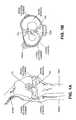
- FIGS. 1A-2illustrate the anatomy of the meniscus in the context of a knee joint.
- the capsule region(the outer edge region of the meniscus) is vascularized. Blood enters the meniscus from the menisculocapsular region 211 lateral to the meniscus.
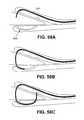
- a typical meniscushas a flattened (“bottom”) and a concave top, and the outer cross-sectional shape is somewhat triangular. The outer edge of the meniscus transitions into the capsule.
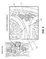
- FIG. 3illustrates the various fibers forming a meniscus. As illustrated in FIG. 3 , there are circumferential fibers extending along the curved length of the meniscus, as well as radial fibers, and more randomly distributed mesh network fibers. Because of the relative orientations and structures of these fibers, and the predominance of circumferential fibers, it may be beneficial to repair the meniscus by suturing radially (vertically) rather than longitudinally or horizontally, depending on the type of repair being performed.
- FIGS. 4A-4Eillustrate various tear patterns or injuries to a meniscus. Tears may be vertical/longitudinal ( FIG. 4A ), Oblique ( FIG. 4B ), Degenerative ( FIG. 4C ), including radially degenerative, Transverse or radial ( FIG. 4D ) and Horizontal ( FIG. 4E ). Most prior art devices for suturing or repairing the meniscus are only capable of reliably repairing vertical/longitudinal tears. Such devices are not typically recommended for repair of radial tears, particularly not arthroscopically/minimally invasively.
- FIGS. 5A-5Cillustrate sutures placed with prior art devices to repair (via suturing) a torn meniscus (showing a longitudinal tear). FIG.
- FIG. 5Aillustrates the results of a repair by a Smith & Nephew “Fast-Fix” device (comparable to a repair by a Biomet MaxFire device).
- FIG. 5Billustrates a Cayenne “CrossFix” device, and
- FIG. 5Cillustrates a repair using an Arthrex meniscal “Viper” device.
- FIGS. 5A-5Cthe devices affecting these repairs require projection through the meniscus and substantially into the capsule region outside of the meniscus, which could potentially damage the nearby major nerves and large blood vessels.
- the prior art devicessuch as those placing the sutures illustrated in FIG. 5A-5C , typically place horizontal mattress suture patterns rather than vertical mattress suture patterns because vertical patterns are considerably more difficult (if not impossible) for surgeons to place when using these devices.
- Vertical mattress patternswould have improved pull through strength because of the aforementioned predominance of circumferential collagen fibers found within the meniscus structure. See, e.g., Boenisch, U.
- the present inventionrelates to devices, systems and methods for repairing a meniscus, and particularly a torn meniscus.
- meniscus repair devicesincluding suture passers, as well as methods of repairing a meniscus, including methods of suturing a meniscus.
- a suturemay be placed entirely arthroscopically.
- two or fewer incisionsmay be made into the knee, and a camera and suture passer may be placed within the knee.
- the suturemay be placed by extending a tissue penetrating element from the suture passer in an arcuate pathway through the meniscus.
- the suture passermay approach the meniscus from the anterior of the knee, and may approach the meniscus tear from the apex of the meniscus.
- the methods described hereinmay include methods of minimally invasively repairing a torn meniscus by joining both sides of a tear in the meniscus and securing the joined entire length of the tear, from the superior surface of the meniscus to the inferior surface of the meniscus, in at least one plane.
- the planemay be in any appropriate section through the meniscus, spanning the tear.
- the planemay be formed by a loop of suture. The device does not significantly penetrate into the structures in the back of the knee (peripheral to the capsule) therefore there is little risk of iatrogenic injury to major knee nerves or vessels during repair.
- the suture passers described hereinmay be used to repair the meniscus without substantially penetrating (or puncturing through) the capsule of the meniscus; the capsular region is highly vascularized, and it is therefore desirable to minimize damage to this region.
- these methodsmay be performed minimally invasively, by minimally invasively accessing the apex of the meniscus with a meniscus repair device (e.g., suture passer, probe, etc.).
- a meniscus repair devicee.g., suture passer, probe, etc.
- an anterior approachmay be used to place the repair device within the interior of the knee; from the interior of the knee the entire procedure may be performed without having to leave the interior of the knee.
- joining both sides of the tear in the meniscusmay include joining both sides without penetrating toward neurovascular structures beyond the posterior capsule of the knee.
- joining the torn surfaces of the meniscusmay mean passing a suture loop completely around the tear in the meniscus from the superior surface to the inferior surface of the meniscus.
- a suture passerto pass a suturing element from the region between the superior surface of the meniscus and the femoral condyle, through the meniscus tissue, into the region between the inferior surface of the meniscus and the tibial plateau, across the inferior surface of the meniscus, and back to the superior surface of the meniscus, without deeply penetrating the posterior capsular region of the knee.
- the suture elementmay be passed from the inferior surface of the meniscus to the superior surface and back to the inferior surface.
- a meniscusby suturing a loop around the meniscus (e.g. around a tear in a meniscus) from the femoral-facing upper outer surface (i.e., the superior surface) of the meniscus to the tibial-facing lower outer surface (i.e., the inferior surface) of the meniscus.
- These methodsmay include the steps of: minimally invasively positioning a suture passer adjacent to the meniscus; using the suture passer to pass a suturing element around the meniscus extending from the upper outer surface of the meniscus, through the meniscus to the lower outer surface of the meniscus, across the lower outer surface of the meniscus, and back to the upper outer surface of the meniscus.
- the suture passermay be minimally invasively inserted in any appropriate manner, including arthroscopically inserting the suture passer into the knee (e.g., near the meniscus).
- minimally invasively inserting the suture passermay include inserting a suture passer having a curved or bent first arm and a straight second arm.
- the suture passermay be inserted with the first arm extended distally and the second arm located proximal to the first arm.
- the first armmay be movable proximally and distally relative to the second arm.
- any appropriate suturing elementmay be used, including each of (alone or in combination): a suture, a suture shuttle, and/or a lead wire.
- the suturing elementis a staple.
- the methodmay also include the step of pulling on the lead wire to draw a suture through and/or around the meniscus.
- the step of using the suture passermay include positioning a first arm of the suture passer adjacent to the upper surface of the meniscus and positioning a second arm of the suture passer adjacent to the lower surface of the meniscus.
- Also described herein are methods of repairing a meniscus by suturing a loop around the meniscus from the femoral-facing upper outer surface of the meniscus to the tibial-facing lower outer surface of the meniscusincluding the steps of: minimally invasively positioning a suture passer adjacent to the meniscus; using the suture passer to pass a suturing element around the meniscus extending from the lower outer surface of the meniscus, through the meniscus to the upper outer surface of the meniscus, across the upper outer surface of the meniscus, and back to the lower outer surface of the meniscus.
- a suture passerincluding the steps of: extending a first arm of the suture passer into a space between the superior surface of the meniscus and the femur; extending a second arm of the suture passer into a space between the inferior surface of the meniscus and the tibia; and passing a suturing element between the first arm and second arm of the suture passer.
- the steps of extending the first arm and the second armsmay be performed in any sequence, or may be performed simultaneously (e.g., extending the first arm of the suture passer comprises extending the first arm before extending the second arm).
- the methodmay also include accessing the apex of a meniscus in the knee joint from an anterior approach.
- the methodmay include extending a tissue penetrator between the first arm and the second arm to capture a suturing element and retracting the tissue penetrator to draw the captured suturing element through the meniscus.
- Also described herein are methods of repairing a meniscus by suturing a vertical loop through and/or around the meniscus from the femoral-facing upper outer surface of the meniscus to the tibial-facing lower outer surface of the meniscusincluding the steps of: minimally invasively inserting a suture passer adjacent to the meniscus; using the suture passer to pass a suturing element around the meniscus in a vertical loop extending from the upper outer surface of the meniscus, through the meniscus to the lower outer surface of the meniscus, radially across the lower outer surface of the meniscus and back to the upper outer surface of the meniscus.
- Also described are methods of repairing a meniscus by suturing a longitudinal loop around the meniscus from the femoral-facing upper outer surface of the meniscus to the tibial-facing lower outer surface of the meniscusincluding the steps of: minimally invasively inserting a suture passer adjacent to the meniscus; using the suture passer to pass a suturing element around the meniscus in a lateral loop extending from the upper outer surface, through the meniscus to the lower outer surface of the meniscus, laterally along the lower outer surface of the meniscus and back to the upper outer surface of the meniscus.
- a meniscus repair deviceconfigured to aid in repair of a meniscus of a knee may include: an elongate body extending distally and proximally; a first arm extending distally in parallel or in line with the elongate body; and a second arm extendable distally at an acute angle from the elongate body, wherein either or both the first and second arms are slideably coupled to move distally and proximally relative to each other such that the device has a first configuration in which the first and second arms form an acute-angled distal-facing opening, and a second configuration wherein the first arm is proximal to the second arm.
- the deviceincludes a handle at the proximal end, and/or a tissue penetrator configured to extend between the first and second arms when the device is in the first configuration.
- the devicemay also include at least one dock in the second arm configured to receive a tissue penetrator extending from the first arm when the device is in the first configuration.
- the tissue penetratormay be configured to extend from the first arm.
- meniscus repair devicesconfigured to aid in repair of a meniscus of a knee, the devices comprising: an elongate body extending distally and proximally; a first arm extending distally in parallel or in line with the elongate body; a second arm extendable distally at an acute angle from the elongate body, wherein either or both the first and second arms are slideably coupled to move distally and proximally relative to each other such that the device has a first configuration in which the first and second arms form an acute-angled distal-facing opening, and a second configuration wherein the first arm is proximal to the second arm; and a tissue penetrator configured to extend between the first arm and second arm and pass a suturing element between the first and second arms.
- a suturing elementmay include: a suture shuttle; a lead wire, a suture, staple, or some combination of these elements.
- Also described herein are methods of passing a suture using a suture passer device and lead wireincluding the steps of: positioning a first arm and a second arm of the suture passer device around a target tissue to be sutured; forming a first stitch through the target tissue with a lead wire by passing a tissue penetrator between the first and second arms and through the target tissue to draw the distal end of the lead wire through the target tissue from the first arm to the second arm; forming a second stitch through the target tissue with the lead wire by passing the tissue penetrator between the first and second arms and through the target tissue to draw the distal end of the lead wire through the target tissue from the second arm to the first arm; pulling a suture coupled to the proximal end of the lead wire through the target tissue by pulling from the distal end of the lead wire; and removing the lead wire from the tissue while leaving the suture in the tissue.
- the step of positioning the first and second arms around the target tissuemay include positioning the first and second arms around a meniscus of a knee.
- Forming the first stitchmay include extending the tissue penetrator through the target tissue from the first arm to the second arm, to engage a suturing element releasably held by the second arm, the suturing element comprising the lead wire, and pulling the suturing element back through the target tissue to the first arm.
- a suture passerconfigured to pass a suture from a first side of a target tissue to a second side of a target tissue and back to the first side.
- a suture passermay include: an elongate body extending distally from a proximal handle; a first arm extending distally from the elongate body; a second arm extending distally from the elongate body and configured to move relative to the first arm to form a distal-facing opening to hold a target tissue; a tissue penetrator configured to extend through tissue within the opening and to carry a suturing element between the first arm and the second arm; a release dock on the second arm configured to hold the suturing element until the suturing element is engaged by the tissue penetrator; and a holding dock on the second arm configured to receive the suturing element from the tissue penetrator.
- the tissue penetratormay extend and retract into the first arm, and in some variations may be formed of a shape memory material configured to extend between the first and second arms in a curved path.
- the tissue penetratoris configured to carry a suturing element (e.g., a shuttle and/or pull wire and/or a suture).
- the second armmay extend distally from the elongate body to form an acute angle with the elongate body, and in some variations may be configured to move distally or proximally relative to the first arm.
- the holding dockmay be configured to lock the suturing element within the second arm.
- Some variations of the suture passers described hereinare generally configured to pass a suture at least twice through the meniscus, i.e., from the femoral surface of the meniscus to the tibial surface of the meniscus, and back to the femoral surface, or from the tibial surface to the femoral surface and back to the tibial surface.
- any of the variations described hereinmay be configured to have an elongate body extending from the distal to proximal direction; the distal-to-proximal direction may be referred to as longitudinal, relative to the device.
- the elongate bodyis relatively stiff or rigid, though flexible, bendable or compliant elongate bodies are also contemplated.
- the elongate bodyincludes a bend near the distal end.
- the devices described hereinmay include one or two “arms” located at the distal end. The arm or arms near the distal end are configured to be positioned adjacent to the meniscus.
- the distal end of the deviceis configured with a pair of arms that are configured to be positioned adjacent to the tibial and femoral faces of the meniscus when the device approaches the meniscus from the inside of the joint (e.g., from the apex of the meniscus); one of the arms may be substantially straight (e.g., in line with rest of the elongate body, and the other arm may be bent at a position proximal to the distal end of the arm, forming the bend.
- the two arms (bent and unbent)may form an acute opening which may fit around the meniscus when approaching from the meniscus.
- the single armmay be bent as described above, or it may be straight, relative to the elongate body of the device.
- both armsare fixed relative to the body of the device.
- the one or more armsare movable.
- one of the armsmay be laterally movable (in the distal/proximal axis) relative to the other arm; in some variations, the bent arm is fixed relative to the elongate axis of the device, while the straight arm is laterally movable.
- the armsare jaws that may be opened and closed (scissorlike) and/or locked into a position (open and/or closed) to either a selectable or predetermined degree.
- tissue penetratorsmay be referred to as needles, knives, or the like, and are generally elongate members configured to extend through the meniscus tissue.
- a tissue penetratortypically has sufficient column strength to penetrate the meniscus and pull or push a suture element (e.g., a suture, suture shuttle, loop/suture puller, etc.) through the tissue.
- the tissue penetratorsinclude elongate, metal or metallic (e.g., Nitinol) needles, which may be formed of a shape memory material; these needles may include a tissue-penetrating (e.g., sharp, pointed) distal end or may have a rounded end.
- the tissue penetratorcomprises a tissue penetrator assembly, including a number of components such as more than one needle, e.g., telescoping needles, sliding blades, etc.
- a suturing elementmay include a suture or any other element configured to draw the suture through the tissue, including a suture shuttle and a pullwire or loop to which one or more sutures may be connected and used to pull the suture through the tissue.
- the devices described hereinmay include a proximal handle having one or more controls for controlling the action of the suture passer.
- the devicesmay include a grip or finger grip region at the proximal end (handle) and a control (e.g., trigger) for deploying the tissue penetrator through the tissue.
- Other controlsmay be used, or integrated with the trigger or with each other, for example, to control transferring/release of the suture element from the tissue penetrator and/or for moving one or more of the arms at the distal end of the device.
- any of the variations of the devices described hereinmay include one or more pre-formed knots or knotting/locking elements for use with the suture being passed.
- any of the device variations described hereinmay be used as part of a percutaneous, minimally invasive procedure, including (but not limited to) minimally-invasively repairing the meniscus.
- the various devices described hereinmay address and/or solve problems and challenges faced by other meniscus suture or repair devices.
- the devices described hereinare configured to fit adjacent (and in some cases over, around or alongside) the meniscus, including one or both of the femoral face and/or tibial face of the meniscus.
- the devices described hereinmay include a narrow distal end region and/or distal shaft region allowing positioning within the narrow confines of the meniscal space. This improvement in geometry may be achieved by reducing the size and/or thickness of the arms.
- the suture passermay include shuttle docks that are narrow or flatter, allowing the arm on which the shuttle dock is present to be narrow.
- the shuttle dockis oriented to minimize the height of the arm.
- the tissue penetrator and/or shuttle and/or shuttle dockmay be adapted to minimize the space needed for the shuttle dock, and therefore the thickness of the arm.
- Part Idescribes suture passer devices having two arms that are positionable around the meniscus, along the femoral surface and the tibial surface, and a single tissue penetrator (e.g., needle) that is configured to extend from and retract into one of the arms (a first arm); the tissue penetrator (or tissue penetrator assembly) is configured to exit from the first arm from a first lateral position (along the length) and extend into the tissue to engage or disengage a suture on the opposite (second) arm, and also to exit from the first arm from a second, more proximal lateral position and extend into the tissue to disengage or engage a suture on the second arm at a second location on the second (more proximal) location on the second arm.
- a controlmay switch the tissue penetrator or tissue penetrator assembly between the first exit position and the second exit position; a toggle, internal switch, deflector or the like may be used to switch between the two exit positions.
- the suture passer devicemay include a two-part tissue penetrator, in which the first part extends from the first arm, and though the meniscus along a first path from the first (e.g., distal) lateral position and the second part is configured to either adjust the trajectory of the first part so that it extends from the first arm along a second path from the second (e.g., proximal) lateral position, or the second part is configured to receive the suture (or suturing element) from the first part and extend from the first arm along a second path from the second (e.g., proximal) position.
- the two-part tissue penetratorincludes a pair of flat or interlocking needles that may slide together and/or separately relative to each other.
- Part II of the disclosureillustrates meniscus suturing devices in which two or more tissue penetrators (e.g., needles) are located on the suture passer for passing the same suture.
- tissue penetratorse.g., needles
- two tissue penetratorsare held on one of the two arms of the suture passer.
- one of the tissue penetratorsis configured to pull the suture from the opposite arm through the tissue and hand off the suture to the second tissue penetrator which then pushes the suture back through the tissue at a second location.
- two tissue penetratorsmay extend simultaneously or sequentially from different lateral positions on a first arm.
- tissue penetratorsmay extend from different lateral locations (e.g., proximal and distal) on the first arm, though the tissue and engage different regions of a suture held on the opposite arm, then pull the suture back though the tissue from either side.
- tissue penetratormay be a flat or substantially flat member.
- Part IIIdescribes meniscus suture passers that include one or more curved tissue penetrator (e.g., needle) extending from a first arm, configured to pass through the tissue and end up back at the same arm, where the suture may be secured.
- the deviceincludes only a single arm from which the tissue penetrator extends and retracts, passing the suturing element (suture, suture shuttle, pullwire/loop, etc).
- the deviceincludes a second arm or other deflector surface which helps guide or direct the tissue penetrator back through the tissue to a second location (e.g. proximal or distal to the starting location of the tissue penetrator).
- the deviceincludes a telescoping tissue penetrator that extends through the tissue with a telescoping (or over- or under-sliding element, as in a two-part construction) element.
- Part IVdescribes meniscus suture passers that may include stapling elements having a pair of tissue penetrators that are coupled together by a flexible element (e.g., suture) between them.
- stapling elementshaving a pair of tissue penetrators that are coupled together by a flexible element (e.g., suture) between them.
- Part Vdescribes other embodiments of suture passers, including accessory elements, and methods of use.
- part Villustrates screw anchors, manual methods of passing a suture to repair a meniscus, and suturing shields to guide the tissue penetrator and/or protect non-target tissue from penetration.
- FIGS. 1A and 1Billustrate the anatomy of the meniscus.
- FIG. 2illustrates the anatomy of the meniscus, including the capsule and associated vascular tissue.
- FIG. 3illustrates the structure of a meniscus.
- FIGS. 4A-4Eillustrate various tear patterns that may be repaired using the invention described herein.
- FIG. 5A-5Cillustrate meniscus repair using prior art devices.
- FIG. 5Dillustrates meniscus repair using a device as described herein.
- FIG. 6Aillustrates a portion of a torn meniscus between a femur and tibia, with a suture passer shown on the right.
- FIGS. 6B-6Dillustrate insertion of the suture passer surgical device into the joint and around the torn meniscus.
- FIGS. 6E-6Hillustrate passing the suture through the meniscus multiple times using the suture passer as described herein.
- FIGS. 6I-6Millustrate removal of the suture passer, retaining the suture around the meniscus.
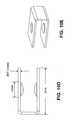
- FIG. 7illustrates one variation of a meniscus suture passer in a delivery configuration, wherein the angled distal arm is extended beyond the opposite arm.
- FIG. 8shows one variation of a tissue penetrator configured as an elongate needle formed at the end of a shape memory push rod.
- FIGS. 9A and 9Bshow one variation of the distal tip region of a tissue penetrator, having a flattened profile and a mating surface for a suture shuttle.
- FIGS. 10A-10Eshow top, side, perspective side and perspective views, respectively of one variation of a suture shuttle configured to mate with a tissue penetrator such as the tissue penetrator show in FIGS. 8 and 9 .
- FIGS. 11A and 11Billustrate attachment of a suture shuttle such as the suture shuttle variation shown in FIGS. 10A-10E to a tissue penetrator such.
- FIGS. 11C and 11Dillustrate attachment of a suture shuttle such as the shuttle shown in FIGS. 10A-10E to a tissue penetrator such as the variation shown in FIGS. 8 and 9 having a recessed region for receiving the suture shuttle flush against the tissue penetrator.
- FIG. 11Eillustrates attachment of a suture shuttle such as the shuttle shown in FIGS. 10A-10E to a tissue penetrator having a recessed region for receiving the suture shuttle flush against the tissue penetrator forming a stripping surface on the side to aid in removal of the shuttle from the tissue penetrator.
- FIG. 11Fillustrate attachment of a suture shuttle such as the shuttle shown in FIGS. 10A-10E to a tissue penetrator having a recessed region for receiving the suture shuttle flush against the tissue penetrator as well as a stripping surface formed by a channel in the tissue penetrator to aid in removal of the shuttle from the tissue penetrator.
- FIGS. 11G and 11Hillustrate attachment of a suture shuttle such as the shuttle shown in FIGS. 10A-10E to another variation of a tissue penetrator having a recessed region for receiving the suture shuttle flush against the tissue penetrator as well as a stripping surface to aid in removal of the shuttle from the tissue penetrator.
- FIGS. 12A-12Cshow additional variations of rectangular suture shuttles.
- FIGS. 13A-13Cshow side, perspective and top views, respectively, of another variation of a suture shuttle.
- FIGS. 13D-13Fshow side, perspective and top views, respectively, or another variation of a suture shuttle.
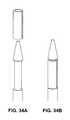
- FIGS. 14A and 14Bshows perspective and side views, respectively of another variation of a suture shuttle.
- FIGS. 15A and 15Billustrate attachment of the suture shuttle variation shown in FIGS. 14A and 14B to a variation of the tissue penetrator similar to that shown in FIG. 11F .
- FIGS. 16A-16Cillustrate attachment of the suture shuttle variation shown in FIGS. 14A and 14B to another variation of the tissue penetrator similar having a recessed region to retain the suture shuttle.
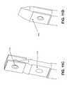
- FIGS. 17A and 17Billustrate operation of the distal end of one variation of a suture passer device during a first stitch ( FIG. 17A ) and a second stitch ( FIG. 17B ).
- FIG. 18shows an enlarged view of the upper arm of the device shown in FIGS. 17A and 17B , during the formation of a first stitch, in which the tissue penetrator is engaging with a suture shuttle releasably held in the upper arm.
- FIG. 19shows an enlarged view of the upper arm of the device shown in FIGS. 17A and 17B during the formation of the second stitch ( FIG. 17B ), in which the tissue penetrator is disengaging the shuttle so that it can be held in the receiving dock in the upper arm.
- FIGS. 20A and 20Bshow side perspective and side views, respectively, of another variation of a dock region configured to accommodate a pull wire.
- FIGS. 21A and 21Bshow side perspective and side views, respectively, of another variation of a dock region configured to accommodate a pull wire including a rim region forming a clip to help releasably retain a shuttle and pull wire.
- FIG. 22is another variation of a suture device arm having a dock (e.g., release dock) for holding a pre-loaded shuttle and pull wire.
- the armincludes a hole or passage through which the pull wire may be drawn when the shuttle (with attached pull wire) is withdrawn across the space between the two arms of the device by the tissue penetrator.
- FIG. 23shows another variation of a dock (e.g., a release dock) for holding a pre-loaded suture shuttle (and/or pull wire).
- a docke.g., a release dock
- the release dockis covered by a frangible covering (e.g., bioabsorbable plastic film) through which the tissue penetrator may extend.
- FIGS. 24A and 24Bshow another variation of a dock such as a release dock and/or holding dock for securing a suturing element.
- a docksuch as a release dock and/or holding dock for securing a suturing element.
- an elastomeric materialFIG. 24B
- a suturing elemente.g., shuttle
- FIGS. 25A-25Cillustrate another variation of a dock for releasably securing a suture shuttle within an arm of the suture passer.
- the dockcomprises a spring-loaded latch.
- FIGS. 26A-26Cillustrate another variation of a dock for releasably securing a shuttle within an arm of a suture passer.
- the dockincludes a spring-loaded latch and pawl.
- FIG. 27is another variation of a suture shuttle including a pull wire
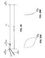
- FIG. 28illustrates an enlarged view of one variation of a pull wire.
- FIGS. 29A and 29Billustrate other variation of a suture and pull wire.
- FIGS. 30A and 30Billustrate one variation of a suture device including arms adapted for use with a pull wire.
- these variationsinclude cut-out regions allowing passage of the pull wire as it is passed between the arms during use.
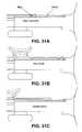
- FIGS. 31A-31Cillustrate indexing features of one variation of a device which allow distal/proximal extension and retraction of an arm of the suture passer to predetermined functional positions for insertion/placement of the device ( FIG. 31A ), positioning around the meniscus and passing the first stitch ( FIG. 31B ), and adjusting the positions on the meniscus and passing the second stitch ( FIG. 31C ).
- the indexing featuresare detents on the body or one arm of the device that interface with tangs on the other arm of the device.
- FIGS. 32A-32Billustrate operation of another variation of tissue penetrator and shuttle, in which the shuttle is hypotube having retaining features (e.g., tabs) that may be secured/released from the tissue penetrator having a matching rounded cross-sectional profile.
- the shuttleis hypotube having retaining features (e.g., tabs) that may be secured/released from the tissue penetrator having a matching rounded cross-sectional profile.
- FIGS. 33A-33Cillustrate another variation of tissue penetrator and shuttle, similar to that shown in FIGS. 32A-32B .
- FIGS. 34A-34Billustrate another variation of tissue penetrator and shuttle, similar to that shown in FIGS. 32A-32B but with a split or gap in the hypotubular shuttle.
- FIGS. 35A-35Gillustrate another variation of a tissue penetrator and shuttle, in which the needle and shuttle are keyed to engage/disengage as the tissue penetrator is extended and retracted between the first and second arms of the suture passer.
- FIG. 36A-36Cillustrate one method of placing two lead wires to pull a suture loop through the meniscus.
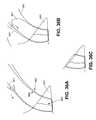
- FIG. 37Ashows another variation of a vertical loop stitch placed by a suture passer as described herein, and extending from the upper outer surface (superior surface) of the meniscus to the lower outer surface (inferior surface) of the meniscus.
- FIGS. 37B and 37Cillustrate a lateral loop of suture placed by a suture passer as described herein, showing a view of the superior surface (femur facing side) of the meniscus in FIG. 37B and the inferior surface (tibial facing side) of the meniscus in FIG. 37C .
- FIGS. 38A and 38Billustrate the use of a barbed suture material with any of the devices described herein in order to suture a meniscus.
- FIGS. 39A-39Dshow a variation of a meniscus suture passer having articulating shafts.
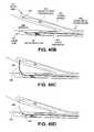
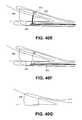
- FIG. 40Ashows one variation of a meniscus suture passer.
- FIGS. 40B-40Gillustrate operation of the suture passer of FIG. 40A .
- FIG. 41Ashows an enlarged view of the lower arm of the suture passer of FIGS. 40A-40G .
- FIG. 41BShows another variation of a meniscus suture passer.
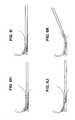
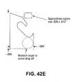
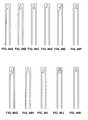
- FIGS. 42A-42Eillustrate variations of tissue penetrating elements which may be used with some of the suture passers described herein.
- FIGS. 43A-43Dillustrate additional variations of tissue penetrating elements which may be used with some of the suture passers described herein.
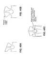
- FIGS. 44A-44Cillustrate variations of tissue penetrating elements which may be used with some of the suture passers described herein.
- FIGS. 44D-44Fillustrate one variation of a dock for receiving a suturing element from a tissue penetrator.
- FIGS. 45A-45Cillustrate variations of tissue penetrating elements which may be used with some of the suture passers described herein.
- FIGS. 46A-46Killustrate variations of tissue penetrating elements which may be used with some of the suture passers described herein.
- FIGS. 47 A 1 and 47 A 2show one variation of a tissue penetrator configured as a grasper.
- FIGS. 47B - 47 D 3illustrate additional tissue penetrators configured as graspers.
- FIG. 48Ashows one variation of a suture passer as described herein.
- FIGS. 48B-48Hillustrate operation of the suture passer shown in FIG. 48A .
- FIG. 48Ishows an enlarged top view of the lower arm of the suture passer of FIG. 48A .
- FIG. 49shows the distal end region of another variation of a suture passer in partial cross-section.
- FIGS. 50A-50Lillustrate operation of the suture passer of FIG. 49 .
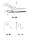
- FIG. 51shows the distal end region (in partial cross-section) of another variation of a suture passer having two parallel tissue penetrators.
- FIGS. 52A and 52Bshow partial views of tissue penetrators for use with suture passers including the variation shown in FIG. 51 .
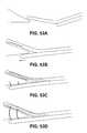
- FIGS. 53A-53Gillustrate operation of the meniscus suture passer of FIG. 51 .
- FIGS. 54A-54Cshow partial views of another variation of a meniscus suture passer configured so that two tissue penetrators hand off a suturing element between them when used to suture a meniscus.
- FIGS. 54D and 54Eillustrate side perspective views of the tissue penetrators used with the suture passer of FIGS. 54A-54C .
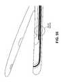
- FIG. 55shows another variation of a suture passer having two tissue penetrators and configured so that the first tissue penetrator hands off a suturing element to a second tissue penetrator during operation.
- FIGS. 56A-56Cillustrate operation of the tissue penetrators for the suture passer shown in FIG. 55 .
- FIGS. 56D and 56Eillustrate both of the tissue penetrators used with the suture passer shown in FIG. 55 .
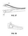
- FIG. 57shows another variation of a meniscus suture passer.
- FIG. 58shows another variation of a meniscus suture passer.
- FIGS. 59A-59Fillustrates operation of the meniscus suture passer shown in FIG. 57 .
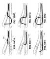
- FIGS. 59 G 1 and 59 G 2illustrate another variation of a meniscus suture passer configured to pass a suture twice through a meniscus.
- FIGS. 59 H 1 and 59 H 2illustrate another variation of a meniscus suture passer configured to pass a suture twice through a meniscus.
- FIGS. 59 i 1 and 59 i 2illustrate another variation of a meniscus suture passer configured to pass a suture twice through a meniscus.
- FIG. 59Jillustrates another variation of a meniscus suture passer similar to those shown in FIGS. 59A-59 i 2 , configured to have an adjustable suture loop size.
- FIGS. 60A and 60Bshow perspective views of portions of a suture passer.
- FIG. 60Cshows a perspective view of another variation of a suture passer.
- FIGS. 61A-61Dshow another variation of a tissue penetrator for a suture passer configured for use with a suture shuttle.
- Described hereinare suture passers for meniscus repair.
- these devicesmay be referred to herein as meniscus repair suture passers, meniscus repair devices, or simply suture passers.
- the devices described hereinmay be configured to repair a meniscus (knee joint meniscus), and have a distal end region that has two arms, at least one of which is extendable and retractable distally/proximally along the longitudinal axis of the device (e.g., “longitudinally).
- the devicehas a deployed configuration with a distal-facing opening configured to fit around the tapering outer surfaces (e.g., the superior and inferior surfaces) of a meniscus.
- the devicealso has an insertion configuration in which one arm (e.g., the bent or angled arm) extends distally beyond the other arm of the device.
- one arme.g., the bent or angled arm
- One or more additional operational configurationsmay be formed intermediate to these two positions, and the device may be switched between these configurations by retracting or extending one or both arms.
- the deployed configuration having a distal-facing openingis typically configured to fit around the inner portion of a meniscus.
- the devicemay form a V-shaped opening which can fit around a meniscus from a lateral (central) approach.
- the distal end of the deviceis divided up into two arms (one of which may be an extension of the elongate body of the device).
- One of the armsis bent, curved, or bendable relative to the other arm and relative to the long axis of the body of the device.
- At least one of the armsis movable distally/proximally relative to the other arm, which may be used to form the angled opening at the distal end region (e.g., the distal-most 3 or less cm) of the device.
- a first armis bent, curved, or bendable at an angle away from the long axis of the device, and the second arm is straight (e.g., parallel or in-line with the long axis of the device).
- the bent or straight arm, or bothis movable distally and proximally (in the direction of the long axis of the device) relative to the other arm. Retracting one of the arms proximally relative to the other arm will form an acute angled opening at the distal end of the device that can be positioned around the meniscus, and a suturing element can be passed between the arms through the meniscus to repair the meniscus.
- the devices described hereinare further configured to pass a suturing element between the two arms and thereby pass the suture through the meniscus.
- the devicesare configured to pass a suturing element at least from one arm to the other and back to the first arm.
- the suture passermay be adapted to pass multiple times between the two arms, or an unlimited number of times.
- the suture passeris configured to pass just twice (e.g., from the first arm to the second arm, and back to the first arm).
- these devicesinclude a tissue penetrating element that is capable of extending between the two arms when the device is in the deployed and intermediate configurations to pass a suturing element through tissue.
- the tissue penetratormay releasably mate with a suturing element (e.g., suture shuttle, suture, and/or wire lead), and may pass the suturing element from a first arm to a second arm, and back to the first arm.
- the arm opposite to the tissue penetrating elementmay have one or more seat/docks for releasably or permanently holding the suturing element.
- the suturing elementis a staple.
- a staplemay act as both the tissue penetrating element (or elements) and the tissue fixation element.
- a staplemay include two tissue penetrating legs and a join region. The tissue penetrating legs of the staple may extend from a first arm through the meniscus where they contact a deflector or, alternatively, an anchor, on the second arm positioned on the opposite side of the meniscus. The tissue penetrating legs may then be secured (by deflection or otherwise anchoring) on the opposite side of the meniscus.
- a staplemay be secured across (e.g., may span) a tear in the meniscus.
- the meniscus repair suture passer devices described hereinmay pass a suture two or more times through the meniscus so that the suture passes from the upper to the lower outer surfaces of the meniscus.
- the angle and/or position of the devicemay be adjusted as necessary before and during the procedure, including between passing the suture through various portions of the meniscus.
- the meniscus repair suture passers describe hereinare adapted for percutaneous use.
- a system including a suture passer as described hereinmay include a first arm, a second arm, a suture-passing tissue penetrating element (e.g., needle), a suturing element to be passed between the two arms, and one or more docks for retaining and/or releasing the suturing elements.
- tissue penetrating elementis a pre-bent wire, ribbon or needle element that is configured to extend from the first or second arm (from which it may be extended and retracted), through tissue (or air), and approach the second or first arm, where it may engage or disengage (alternately or cyclically) a suture shuttle held in a shuttle dock.
- the first arm of the suture passermay be configured for distal/proximal movement, e.g., forward and backwards axially along the long axis of the device.
- the suture passermay be configured to include two or more stops corresponding to different operational configurations.
- the devicemay include a first stop in which one arm is fully retracted axially, forming the distal opening for the meniscus, and a second stop (extended stop) when one arm is fully extended distally forming a device having bent distal end (formed by the extended arm).
- the suture passerincludes a third or more (e.g., intermediate) stop(s) in which an arm is partially extended distally.
- FIG. 7illustrates one variation of a meniscus suture passer 700 , as described herein.
- the suture passerincludes an elongate main body 703 extending the length of the device.
- the proximal end of the device 700includes a handle 701 .
- the distal end of the main body 703 of the devicemay be referred to as a first arm forming the distal end of the device.
- a slider 705is movably coupled to the main body.
- the distal end of the slider 705forms the second (e.g., “upper”) arm. Sliding the slider 705 proximally relative to the first arm (and main body 703 ) will result in the formation of an angled opening.
- the openingis roughly V-shaped, in which one side is substantially flat while the other side is angled relative to the flat side.
- the distal end of the slideris rounded or blunted to prevent damage to the meniscus when operating the device.
- the distal end of the slider(angled or second arm) may be enlarged relative to the more proximal region of the slider.
- the slidermay also include a slider control (e.g., finger control 711 ) which may be manipulated manually or automatically to move the slider distally or proximally.
- a similar control on the opposite side(e.g., on the main body) may also be included to slide the first arm (the main body) relative to the slider when it is desirable to hold the slider in a fixed position relative to the patient, for example.
- one or more arms of the suture passermay be bent or curved.
- the second (slider) arm of the deviceis bent or angled “upwards” away from the first arm, or from the long axis of the device, including the first arm, so that the ends region of the second arm (the upper arm) relative to the long axis is bent at approximately the angle formed by the superior surface of a meniscus relative to the inferior surface of the meniscus.
- the anglemay be fixed (e.g., at an acute angle of approximately 10°, 15°, 20°, 25°, 30°, 35°, 40°, 45°, 60°, etc. including any angle between 1° and 90°); for example, the angle may be between 20 degrees and 50 degrees.
- the angle between the first and second armsis variable.
- the angleis adjustable (e.g., either or both arms may be bent or adjusted to adjust the angle there between).
- the angle of the bend in the upper (second) armmay be approximately the average angle between the superior and inferior faces of the meniscus; for example, the angle may be approximately 35 degrees ⁇ 2 degrees, ⁇ 5 degrees, ⁇ 7 degrees, ⁇ 10 degrees, ⁇ 15 degrees, etc.
- the bendforms an acute angle with the lower (second) arm when the second arm is extended distally.
- the distal end region of the second armmay be bendable from a straight or pre-bent configuration into the final bend configuration.
- a tissue penetrator(not shown) is housed within the first arm 713 , which in this example is integral with the main body 703 .
- the first armextends distally, in-line with the proximal-distal axis of the elongate main body; in some variations the first arm is separate from the main body, but extends in parallel with the distal/proximal axis of the main elongate body of the device.
- a second, bent arm formed by the slider 705may include one or more shuttle docks.
- the second armmay also be referred to as the slider, since it is slideably coupled with the elongate body (e.g., main body) and/or the first arm of the device.
- the distal end of the second armextends at an angle from the main body.
- the angleis not constant over the entire length, as the distal tip of the second arm is rounded (having a region almost in parallel with the long axis of the elongate body and first arm).
- an acute-angled, distal-facing 719 openingis formed between the first arm and the second arm which may be positioned around the apical region of a meniscus, e.g., the tapered region opposite from the capsular region.
- FIGS. 17A and 17Bdescribed in greater detail below, show the acute-angled opening formed by the first and second arms.
- the second, upper arminclude one or more seats or docks (e.g., shuttle dock) for holding a suturing element within the second arm.
- the device of FIG. 7is configured to have two docks.
- One of these docksmay be configured as release dock which may hold the suturing element (e.g., suture, suture shuttle and/or lead wire) within the dock and release the suturing element from the dock to engage the tissue penetrator;
- the second dockmay be identical to the first dock, or it may be configured as a holding dock that is configured to receive the suturing element from the tissue penetrator but not release it back to the tissue penetrator.
- the first dock and the second dockmay be separated from each other along the length of the second arm.
- a release dockis located near the distal tip of the second arm and a holding dock is located proximal to the release dock. In some variations these positions are reversed.
- the second armincludes more than two docks.
- the release dockmay be pre-loaded with a suturing element.
- a shuttle dockmay be configured to releasably engage a suture shuttle (or other suturing element).
- the suture shuttlemay be passed between a shuttle dock and the tissue penetrating element that may extend between the first and second arms.
- a tissue penetratormay extend from within a first arm, though the meniscus tissue, and engage a suture shuttle held in a dock in the second arm; the tissue penetrator with attached shuttle may then retract back through the tissue to the first arm. If a pull wire and/or suture is attached to the shuttle, the distal end of the pull wire and/or suture will be pulled back from the second arm to the first arm.
- the first armmay be retracted proximally relative to the second arm, or the device may be otherwise repositioned on the meniscus (without requiring that the device be removed from the meniscus).
- the tissue penetratormay then be passed back through the tissue to engage either another shuttle dock, or the same (first) shuttle dock, and release the suture shuttle within this dock; the tissue penetrator may again be withdrawn, leaving the suture and/or lead wire stitched through the meniscus from a first (e.g., superior) surface of the meniscus to an opposite (e.g., inferior) surface of the meniscus and back to the first surface of the meniscus. Additional stitches may be made, or the device may be withdrawn from the knee and the suture pulled taut and secured in position.
- Suture shuttle and tissue penetrating elementmay be configured as described in the descriptions previously incorporated by reference (e.g., U.S. Ser. No. 11/773,388 and U.S. Ser. No. 12/291,159).
- the shuttlemay be a clip (e.g., a triangular-shaped clip) to which a suture is secured; the clip may be configured to snap on an off of the tissue penetrating element (e.g., a curved needle having a triangular cross-section).
- the suture shuttle with a suture attachedis pre-loaded into a shuttle dock on the first arm of the device.
- FIGS. 10A-16Cillustrated in more detail below, illustrate variations of suture shuttles and tissue penetrators which may be used.
- tissue penetrator or penetrating elementis held within and extended from and retractable into one arm of the suture passer. Once it exits the arm of the suture passer, the tissue penetrator extends across the gap between the two arms, through any intervening meniscus tissue, where it can transfer a suturing element between its distal tip region and a dock or seat on the opposite arm.
- the suture passerfollows a predetermined pathway between the two arms of the device, so that it reliably encounters the dock and can exchange the suturing element (e.g., suture shuttle).
- the distal end region of the tissue penetratormay be adapted to releasably engage the suturing element and also to allow penetration though the tissue.
- tissue penetratoris a curved member that retracts or extends from one of the arms.
- a tissue penetrating membermay be a curved or curvable element that retracts completely into a housing in the distal end region of the first arm, and extends outwards in a curved pathway.
- the tissue penetratormay be configured to extend from the distal end region of the second arm, and to retract fully into the body of the second arm; in some variations a portion of the tissue penetrating member may extend from the first arm even when fully retracted into the first arm.
- the second arm or other portions of the suture passermay be configured to include a track or pathway for the tissue penetrating member so that the tissue penetrating member does not prevent the first arm from extending or retracting axially relative to the body of the device.
- the tissue penetratoris pre-bent or pre-curved into a curved shape configured to allow the tissue penetrator to pass in a curved or arced pathway from within a first arm and across the gap between the first and second arms, and engage a seat or dock on the second arm.
- the tissue penetratormay be formed of any appropriate material, including shape-memory materials.
- the tissue penetratormay be formed of a shape memory polymer or alloy.
- the tissue penetratorcomprises a nickel titanium material (e.g., Nitinol).
- the tissue penetratoris typically pushed and/or pulled to extend and retract it from the first arm.
- the proximal end of the tissue penetratormay be connected to a push/pull rod.
- FIG. 8illustrates one variation of a pre-formed tissue penetrator formed as part of a nickel titanium push rod or wire.
- the tissue penetratorwhich may also be referred to as a needle, if formed at, or otherwise joined to, the distal end of the rod or wire 809 .
- the distal end in this examplehas been flattened (e.g., by grinding) and pretreated to form the needle tip with a curve 805 , as shown.
- the distal endhas therefore been ground flat 803 , and is continuous with an elongate rod length 809 .
- the rodhas been modified to include a retaining structure, e.g., ring, for holding the device within the suture passer while allowing it to be extended and retracted for operation.
- the proximal end in this examplealso includes a threaded region to connect to a plunger and/or handle member that allows the rod to be advanced and withdrawn within the elongate body of the suture passer (and the first arm) to extend and retract the tissue penetrator.
- all or a portion of this tissue penetrator assemblyis keyed to prevent rotation of the needle.
- the bodymay include a groove or a protrusion to mate with a channel or other element within the suture passer and prevent rotation.
- the variation of the device described in FIGS. 7 and 8utilize a one piece pre-formed Nitinol needle that has been heat set into the desired shape.
- the entire length of the needlemay be made from a flat wire; alternatively, the entire length may be made from a round wire, as shown in FIG. 8 (which may be partially or complexly ground or otherwise shaped to include the necessary flat regions.
- the needle (tissue penetrator) assemblyis formed of a combination of a round wire for the proximal shaft with a distal end ground/cut flat. This configuration may allow sufficient stiffness and axial push to drive the penetrator through tissue, but enable sufficient flexibility at the distal tip so it can be shape set.
- the distal end region of the tissue penetratoris configured to receive a suturing element such a suture shuttle.
- the region of the tissue penetrator just proximal to the most distal tip regionmay be configured to retain a suture shuttle or other suturing element.
- the most distal region(the actual distal tip) is typically tapered and/or sharpened to allow the device to penetrate though the tissue.
- the distal tip regionis shaped to receive, retain and/or release a suturing element.
- FIGS. 9A and 9Billustrate one variation of a distal tip of a device that is shaped to penetrate the meniscus tissue while retaining (and later releasing) a suture shuttle.
- the distal tip regionis configured to receive a shuttle by including a recessed region 901 that allows the shuttle to be held by the needle with a low profile.
- the distal tip regionalso includes a hole or opening 903 to mate with dimple on the suture shuttle; in some variations other mating elements (e.g., buttons, tabs, slots, etc. may also be included to mate the tissue penetrator with the suture shuttle.
- the tissue penetratoralso includes a stop 905 against which the shuttle may be held in position. This recessed region is configured to match the approximate size of the inner diameter of the shuttle such that the outer diameter of the shuttle matches the outer diameter of the tissue penetrator, forming a flush connection between the two components.
- tissue penetrator variation shown in FIGS. 9A and 9Bis a flattened (ribbon-like) tissue penetrator, having a roughly rectangular cross-section. This variation may be referred to as a rectangular needle.
- FIGS. 10A-10Eillustrate one variation of a suture shuttle that may be used.
- a suture shuttlemay be used to connect the tissue penetrator with a suture or with a lead wire that may be passed through the tissue to form a suturing pattern.
- the suture shuttles illustrated hereinare typically clip-on or snap-on (e.g., snap-fit) elements that secure over and/or around the distal end region of the tissue penetrator and with a dock or seat on an arm of the suture passer.
- Other variationsmay include internal structures that are held within the tissue penetrator, shuttles that are held by non-friction fit methods (e.g., magnetically secured, chemically secured, etc.).
- the suture shuttleis configured to resiliently fit over the tissue penetrator distal tip and reside on a region proximal to the distal tip.
- the suture shuttleincludes a flex region or point allowing it to flex “open” to fit over the tissue penetrator.
- the suture shuttleis partially or completely open on at least one side, and is formed of a resilient material, such as a metal alloy. Any appropriate biocompatible material may be used, including stainless steel, plastic, alloys, shape memory materials (e.g., Nitinol), or the like.
- the suture shuttlecomprises stainless steel (17-7PH or MP35N).
- the shuttle illustrated in FIGS. 10A-10Emay also be referred to as spring form shapes that snap onto the tip of the needle.
- the dimensions shown in any of the figures hereinare intended for exemplary dimensions only, and may be adjusted without deviating from the principles of the invention. Any of these dimensions may be adjusted by a percentage of their indicated value; for example, any of the dimensions may be adjusted by ⁇ 2%, ⁇ 5%, ⁇ 10%, ⁇ 20%, ⁇ 30%, ⁇ 50%, ⁇ 100%, ⁇ 150%, ⁇ 200%, etc.
- any of the shuttle variations described hereinmay also include one or more locking or retention features.
- the shuttlein FIGS. 10A-10E , the shuttle includes a dimple 1005 or protrusion that is configured to mate with a mating feature (e.g., hole or recess) in the tissue penetrator to retain the shuttle on the tissue penetrator.
- a mating featuree.g., hole or recess
- FIGS. 11A to 11Bshow the attachment of a suture shuttle such as the one in FIGS. 10A-10E to the distal end region of a tissue penetrator.
- the distal tip of the tissue penetratoris narrower and smaller (e.g., tapered) 1101 than the opening into the shuttle and the shuttle snaps over the distal tip region so that the protrusion on the shuttle mates with the depression or hole on the tissue penetrator (this arrangement may be reversed so that the protrusion is on the tissue penetrator, for example).
- the suture shuttle in this exampleis not held in a recess flush against the outer surface of the tissue penetrator; this configuration may be useful when stripping the shuttle off of the tissue penetrator to transfer it into a dock after passing through the tissue.
- the back edge of the shuttle 1105 extending above the tissue penetratormay serve as a contact to apply force to remove the shuttle from the tissue penetrator.
- FIGS. 11C and 11Dillustrate a variation of a tissue penetrator in which the shuttle is held flush with the rest of the needle within a pocket formed (e.g., ground) into the needle.
- the dimple or protrusion on the shuttlemay help secure and position the shuttle on the tissue penetrator.
- FIGS. 11E and 11Fshow variations of tissue penetrators which also include a recessed region for holding the shuttle flush against the tissue penetrator, however these versions also include leverage points located proximally on the distal end region (proximal to the seating region) for helping remove the shuttle from the tissue penetrator.
- the needleis narrower in width than the shuttle, so that one side of the shuttle extends slightly from the tissue penetrator 1137 when the suture shuttle is held on the needle; the dimple/protrusion may help maintain this position.
- This lip regionmay provide a surface that can be used to remove the shuttle from the needle (e.g., to strip it off of the needle) when transferring the shuttle to a dock.
- FIG. 11Ethe needle is narrower in width than the shuttle, so that one side of the shuttle extends slightly from the tissue penetrator 1137 when the suture shuttle is held on the needle; the dimple/protrusion may help maintain this position.
- This lip regionmay provide a surface that can be used to remove
- the needleincludes a groove or channel 1135 in the inner radius of the need exposing the proximal-facing edge of the shuttle, even though the shuttle resides within a pocket 1131 in the distal end region of the device 1131 .
- FIGS. 11G and 11Hillustrate a similar variation of the needle. In this variation, a portion of the proximal edge of the recess on the tissue penetrator has been removed 1143 , preventing it from interfering with the corners of the shuttle as it is inserted onto the needle or removed from the needle.
- FIG. 11Galso illustrates the stop features 1147 formed at the proximal end of the recess which may help position the shuttle on the needle. In this variation the protrusion may not be necessary given the recess formed on the needle, as well as the snap feature (proximal recess edge 1145 ) which may also help to secure the shuttle on the needle.
- FIGS. 12A-12COther variations of shuttles are shown in FIGS. 12A-12C .
- the shuttleis roughly rectangular (“box” shaped) having at least one partially open side. This open side may help the shuttle to flex open/closed so that it can reliably secure over the distal end region of the suture passer.
- the dimplehas been replaced with a tab or protrusion 1205 .
- the protrusionhas been replaced with a tab 1205 ′.
- this tabmay be frangible; for example, the tab may be stripped off or deformed when removing the shuttle from the tissue penetrator after transferring it back and forth through the tissue.
- FIGS. 13A-13FOther exemplary shuttles are shown in FIGS. 13A-13F .
- the shuttlesmay be formed of any appropriate biocompatible material, including shape memory materials such as nickel titanium, stainless steel, etc.
- FIGS. 14A-14Bshow another variation of shuttle
- FIGS. 15A and 15Billustrate the coupling of the shuttle with the distal end of a tissue penetrator.
- FIGS. 16A to 16Calso illustrate coupling of a shuttle with the distal end of a tissue penetrator.
- any of the tissue penetrator configurations described hereinmay be used with any of the shuttle configurations described herein, although some combinations may be more optimally matched for coupling and/or uncoupling.
- suture passers described hereinare configured to form a stitch extending from a first side of a tissue to the opposite side of the tissue and back to the first side again; in some variations the devices are limited to passing twice and thereafter must be re-loaded to pass the suture again.
- Such variationsmay be referred to double pass suture passers, because they are configured to pass a suturing element (e.g., suture shuttle, suture, and/or pull wire for pulling a suture) back and then forth through the tissue.
- a suturing elemente.g., suture shuttle, suture, and/or pull wire for pulling a suture
- FIGS. 17A and 17Billustrate a portion of suture passing configured to pass two stitches through a meniscus.
- the upper armwhich extends at an acute angle from the elongate body of the device, includes two dock regions.
- the distal most dockis a retaining dock (release dock) that is configured to hold a suturing element (e.g., shuttle) until the tissue penetrator extending from the lower arm engages the suturing element and releases it from the release dock.
- a suturing elemente.g., shuttle
- FIG. 17Athe upper and lower arm are both extended distally forming an acute-angled opening which can be placed over or around the tapered side of a meniscus. This configuration may be referred to as the first deployed position, and the first stitch may be pulled from this configuration.
- the tissue penetrator 1704is shown extending in a curved path from the first (lower) arm to the second (upper) arm to engage the distal most dock 1707 . Retracting the tissue penetrator 1704 back into the first arm and thereby drawing the suture shuttle (and any associated suture and/or pull wire) through the tissue from the superior side of the meniscus to the inferior side of the meniscus forms the first pass or stitch through the tissue. If desired, the device may then be repositioned (e.g., moved longitudinally or circumferentially along the meniscus if a longitudinal/circumferential stitch is to be performed), or it may be left in place to form a lateral loop or stitch.
- the suture passer devicemay include manual or automatic indexing to adjust the relative positions of the first and second arms whereby the tissue penetrator extending from the first arm is aligned with the first and second docks on the opposite arm.
- the first and second armstill form an acute-angled and distal facing opening which may surround the meniscus, however the lower arm is located more proximally than in FIG. 17A .
- Both the docks in FIGS. 17A and 17Bmay include a retention mechanism (e.g., retaining pin, etc.) 1707 for holding the suture shuttle in position.
- the shuttleis preloaded in the distal most dock, and can be engaged by the tissue penetrator when the device is in the 1 st stitch position.
- a retaining clip inside the tip of the sliderholds the shuttle in place.
- the pre-formed needlepicks up the shuttle from the first dock while in the 1 st stitch position, and pulls it back into the main body tip.
- the slidercan then be retracted by the spring loaded plunger (see FIG. 7 , for an example), allowing the slider (upper arm) to be retracted to the 2 nd position from which the needle can drop off the shuttle into the second dock when the device is in the second stitch position.
- there is a stripping mechanismsuch as a clip in the second dock that strips the shuttle off of the needle as it is retracted back into the main body.
- FIG. 18shows an enlarged view of a first or release dock.
- a machined block 1809holds a clip 1805 in place.
- a suture shuttle 1811is shown held within the dock, while a tissue penetrator 1813 is shown engaging the shuttle to remove it from the dock.
- the block 1809provides a stop features that acts as a hard stop for shuttle, preventing it from overshooting.
- a sheet metal clip 1805squeezes the shuttle to hold it in place, but doesn't have any positive retention features; in some variations (e.g., see FIGS. 25A-26C ) positive and releasable retention mechanisms are included and used to retain the shuttle.
- FIG. 19is an enlarged view of the second seat or dock within the upper arm.
- This dockis configured as a holding dock because it receives the shuttle from the tissue penetrator but does not readily release the suture shuttle back on the tissue penetrator.
- the dock in this examplealso includes a machined block 1903 to hold the elements of the dock in position.
- a sheet metal clip surrounding the dockallows for needle insertion, but is also configured to strip-off the shuttle from the tissue penetrator upon needle retraction.
- FIGS. 20A and 20Aillustrate other variations of configurations for docks which may be used.
- the dockincludes an internal clip 2001 into which the shuttle is held.
- the dockalso include a machined block 2002 that acts as a stop.
- a bump on one side of clipholds the shuttle in a known location within the dock, and may “hold” the shuttle within the dock less securely than when the shuttle is engaged by the needle, which may have two such bumps for mating with the shuttle more securely, allowing it to be withdrawn.
- the asymmetric positioning of the shuttle 2005 within the dockmay also allow room for an attached pull wire 2003 extending from the side of the suture shuttle.
- FIGS. 21A and 21Bshow another variation of a shuttle dock.
- the shuttle dockincludes a ledge on the clip that provides a stronger hold than the variation shown in FIGS. 20A and 20 b.
- the suturing elementincludes a pull wire or zip wire that is configured to be drawn through the tissue prior to pulling a suture through the tissue.
- the pull wiremay be managed by one or more structures on the device.
- the deviceincludes a channel or passage 2201 on the upper arm for the pull wire 2203 .
- pulling on lead wirewill not dislodge shuttle.
- this variationis generally very secure when inserting the preloaded device into knee. The surgeon may even yank on lead wire to ensure shuttle is in the proper location for passing.
- FIGS. 23 and 24A-24 billustrate alternate variations of shuttle docks for hold a shuttle and releasing it onto a tissue penetrator.
- the shuttle dockis a retaining dock which is sealed off by a frangible covering (typically made of a biocompatible and/or bioabsorbable material).
- the tissue penetratormay extend through the covering to engage with the shuttle.
- the shuttletypically cannot fall out of the dock.
- the devicemay be configured as single-use, since the shuttle may not be reloadable, making it difficult to reuse the device.
- the covering filmcan be made of bioabsorbable material so that any left-over pieces in the knee don't cause issues.
- the thin plastic film shown covering the shuttle within the dockis bonded to lead-in on pocket; a needle may be used to pierce the covering film to retrieve shuttle.
- the dockincludes an elastomeric body (e.g., rubber, silicone, etc.) 2403 into which the shuttle is held.
- elastomeric bodye.g., rubber, silicone, etc.
- the elastomeric bodyallows the dock to flex to receive the shuttle (and tissue penetrator), while retaining the shuttle.
- the dockalso includes a lead-in region 2407 to guide the needle into the dock and a stop feature 2405 to stop the needle from extending beyond the region where the shuttle may be docked and undocked.
- FIG. 24Bshows an enlarged perspective view of the elastomeric body 2403 surrounding the dock.
- the bodyincludes a channel 2409 for management of a lead wire.
- FIGS. 25A to 25Cillustrate another variation of a release dock.
- the dockincludes a spring loaded latch that is triggered by contact with the tip of the tissue penetrator (needle) to release the shuttle onto the tissue penetrator.
- the spring loaded latchholds the shuttle in position, as shown.
- FIG. 25Ba tissue penetrator inserted into the dock contacts the latch and forces it up, releasing the latch from holding the shuttle, so that (in FIG. 25C ) the tissue penetrator can be withdrawn, pulling the shuttle with it.
- FIGS. 26A-26Cillustrates the operation of a tension spring loaded latch mechanism including a pawl.
- the latchholds the shuttle within the dock, while the tension spring loads the latch against the pawl.
- the tissue penetrator(needle) may insert into the dock and push the pawl out of the way, as shown in FIG. 26B , allowing the latch to rotate.
- the tissue penetratormay then capture the shuttle and be withdrawn from the dock, as shown in FIG. 26C .
- the latch and pawlare held out of the way by the spring, so that they don't interfere with the removal of the needle and shuttle.
- a pull wiremay be used to suture the tissue.
- the pull wiremay also be referred to as a zip wire, a pull loop, a leash, a lead, a tether, or the like.
- the pull wireis typically a thin, flexible wire-like element that may be drawn through the tissue by the suture passer in a suture pattern.
- the distal end of a pull wiremay be pulled through the tissue before the suture is pulled through the tissue, and in some variations, even before the suture is attached to the pull wire.
- one or more suturesmay be coupled to the proximal end of the pull wire and the pull wire may be drawn through the tissue to pull the suture into place; the pull wire may be subsequently removed from the tissue.
- the pull wire usedmay be a small diameter wire/cable.
- the smaller diameter wirewill take much less force that a larger diameter suture to be stitched and may exert minimal forces on the shuttle.
- the pull wireis made from stainless steel cable (e.g., 19 strands wound together as 1). This configuration may allow a great deal of flexibility and may also allow the pull wire to be welded to a stainless steel shuttle. In some variations the pull wire is made from a single wire or several other cable configurations. It can also be made of any other appropriate material, such as nickel titanium (e.g., Nitinol), elgiloy, polymeric materials, etc.
- FIG. 27illustrates one variation of the distal end of a pull wire 2702 that has been attached to a suture shuttle, as described above.
- the pull wire 2702has been welded to a shuttle 2703 .
- FIG. 28Another example of a pull wire is shown in FIG. 28 , including exemplary dimensions.
- the pull wire 2801is coupled to a shuttle 2803 at its distal end and extends for some length (e.g., approximately 10 inches, though shorter or longer wires may also be used).
- the proximal end of the pull wireforms a loop 2805 through which a suture 2807 may be threaded either before or after the shuttle and pull wire have been passed through the tissue.
- the proximal end of the pull wire in this exampleis looped onto itself and held by heat shrink tubing 2811 ; any appropriate method of forming a loop or suture attachment site (including non-loop attachment sites, such as clips, clamps, adhesives, splicing, etc.) may be used.
- the pull wirecan also be coated (i.e., with PTFE) to prevent tissue damage as it is pulled through tissue.
- FIGS. 29A and 29Billustrate another variation of pull wires as described herein.
- the pull wireforms a loop; in this example, the loop may be biased to open as shown, making it easy to load a suture on the pull wire after or before it has been passed through the tissue. This may be particularly beneficial when loading the pull wire with the suture from within the tissue (e.g., within the knee), for example, arthroscopically.
- the pull wireincludes a smaller loop region. In both of these examples, the pull wire is shown attached to a suture shuttle.
- FIG. 30Ashows another variation of an upper arm of a suture passer including a pair of docks for receiving a suturing element which may include a pull wire.
- the upper armincludes a cut-out channel 3003 in the lateral side of the arm to allow a pull wire to extend from the upper arm.
- FIG. 30Bshows an enlarged view of a portion of the lower arm including a tissue penetrator 3004 retracted into the lower arm 3006 .
- the tissue penetratorincludes a suture shuttle coupled to a pull wire 3012 , and the pull wire extends from a channel 3008 in the lower arm.
- the shaft of the suture passermay be articulating which may allow the device to reach different regions of the meniscus.
- the articulating shaftmay be configured to bend or flex (articulate) at a predetermined position along the length of the device, to a predetermined degree/angle or range of angles (e.g., between 1 and 90 degrees, between 5 and 45 degrees, between 10 and 30 degrees, 45 degrees, 30 degrees, etc.), and in a predetermined direction or directions (e.g., “up/down,” radially in the direction of the upper arm; side to side, etc.).
- the elongate shaft shown in FIG. 7Amay include on or more bendable, jointed or the like.
- the elongate shaftis relatively stiff until actuated to bend; this may allow the device to be positioned more precisely, even while the distal end of the device (which may form a distal-facing opening) is positioned around the meniscus.
- FIGS. 39A-39B and FIGS. 39C-39Dillustrate two variations of meniscus suture passers having articulating elongate shafts.
- FIG. 39Ashows a side view of a meniscus suture passer including a distal region including the first and second arms 3901 wherein the upper arm is a slider that may slide proximally and distally.
- This variationincludes a hinged or articulating joint region 3905 which may be bent by the user (e.g., by activating a control on the handle region, not shown) to bend the device up/down (e.g., where up is in the direction of the slidable upper arm, and down is in the direction of the straight lower arm). This is illustrated in FIG. 39B .
- FIG. 39Cshows another variation of a suture passer having a hinged or articulating joint region 3907 .
- FIG. 39shows a bottom view of the device. In this variation the device may be articulated left or right (e.g., side-to-side), as shown in FIG. 39D .
- the location of the joint or articulating regionmay be more proximal or more distal.
- the articulating regionis lockable in either the straight (unbent) or the articulated (bent) configuration.
- the distal end region(just proximal to the region forming the distal-facing opening) is configured to articulate.
- the shaft and/or the arms, including any slider region or arm,may be configured to articulate.
- the upper arm or slidermay be configured to articulate with a hinge region, while the lower arm (extending from or continuous with the elongate body shaft) may be made bendable (e.g., may be formed of a bendable material, such as Nitinol, etc.) to follow a bend at a fixed position relative to the upper arm.
- the devicemay be configured to bend either before, during, or after the distal-facing opening has been formed between the upper and lower arms by extending (or retracting) one or both arms, as described above, and illustrated in FIG. 17A .
- the devicemay be configured to bend in the sideways direction (e.g., FIG. 39D ) or articulate only when the distal-facing opening is formed between the upper and lower arms 3901 .
- bending or articulation of the devicemay allow it to enter the inner region of the knee joint (the region between the two menisci) from an anterior approach, and be articulated or bent at an angle to treat even regions of the lateral or medial meniscus that are located towards the anterior of the knee.
- the devicemay be manipulated within the knee joint to suture a meniscus without penetrating the capsule or more capsular end of the meniscus, thereby avoiding the more highly vascular region, preventing further injury.
- the meniscus treatment devices described hereinmay be used with imaging (e.g., arthroscopic imaging).
- the devices described hereinmay be adapted to include on-board imaging or one or more channels for imaging.
- the suture passer illustrated in FIG. 7may include an imaging sensor at or near the distal end for imaging the tissue as the device is positioned and/or operated.
- the deviceincludes an imaging modality (e.g., fiber optic, optical bundle, CMOS, CCD, etc.) sensor located to visualize in the distal-facing direction.
- the imagingmay include a sensor (or channel for a sensor that is positioned on the upper or lower arm to face distally. In some variations the sensor is located just proximal to the bend in the upper arm. Imaging information may be fed back through the body of the device, or transmitted from the tip wirelessly, and be presented to the physician, stored, or otherwise processed.
- Operation of a meniscus suture passertypically includes moving the upper arm and/or lower arm relative to each other in order to coordinate passing a suturing element between the upper and lower arms by engaging a tissue penetrator and two or more seats or docks.
- the tissue passerBefore passing a suturing element between the upper and lower jaws, the tissue passer be set into a delivery configuration for insertion into the knee and around the meniscus.
- one arme.g., the bent or angled arm, referred to as the slider in FIG. 7
- the slider in FIG. 7may be extended fully distally (or the lower arm retracted proximally) so that the lower arm is proximal to upper arm, as shown in FIG. 7 .
- This configurationhas a narrow (though slightly bent) diameter, and may make insertion of the device into the knee region easier.
- the upper and/or lower armmay be positioned so that the tissue penetrator crossing between the two arms will engage and transfer the suturing element.
- the tissue penetratortypically moves along a predetermined pathway between the upper and lower jaws, and moving either (or both) the upper and lower jaw may determine which of the two or more docks engages with the suture passer.
- the first and second armsshould be in a first stitch configuration, wherein the upper, bent, arm and the lower, straight, arm are both extended distally so that the tissue penetrator can cross through the gap between the arms, including any meniscus tissue between the arms, and engage with a suturing element in the first dock.
- indexing tabs, marks, detents, locks, stops, or the likewhich indicate the correct relative positions of the upper and lower arms in order for the tissue penetrator to mate with the appropriate dock and engage with the suturing element (e.g., shuttle, pull wire, and/or suture).
- suturing elemente.g., shuttle, pull wire, and/or suture
- the relative positioning of the first arm and the second arm to form the first and second stitches through the tissuemay need to be somewhat precise.
- positive indexing featuresmay be built into the suture passer to accurately locate the slider position (upper arm) relative to the needle/shuttle (the lower arm).
- the lower armwhen passing the second stitch from the inferior side of the meniscus to the superior side of the meniscus, the lower arm may be slightly retracted proximally, relative to the upper (bent) arm, allowing the tissue penetrator to extend towards the second dock into which the shuttle may be released.
- FIGS. 31A to 31Cillustrate one example of a suture passer adapted to include stops or detents indicating the different relative slider configurations.
- the upper arm (slider)includes one or more tangs that mate with a detent on the lower arm and/or elongate body of the device. As the tang engages the detent, it holds the upper and lower arms in this configuration, which may also be marked or otherwise indicated on the device.
- the upper arm (slider)is fully extended distally, so the device is in the delivery configuration (e.g., see FIG. 7 ).
- FIG. 31Athe upper arm (slider) is fully extended distally, so the device is in the delivery configuration (e.g., see FIG. 7 ).
- FIG. 7the delivery configuration
- FIG. 31Bshows the device in the “first stitch” configuration, with the slider fully retracted proximally so that a tissue penetrator from the lower arm can extend to engage a shuttle and/or lead wire in the upper arm (e.g., see FIG. 17A ).
- FIG. 31Cshows the “second stitch” configuration, in which the upper arm is in an intermediate configuration (e.g., see FIG. 17B ).
- the devicesinclude markings on the slider (upper arm) and main body to indicate the functional position of the two arms.
- the suturing devices described abovemay also be configured to automatically shift between these different configurations.
- the suturing devicemay include a handle with a control that is operated by a single button, knob, switch, or the like that automatically converts the configuration from the delivery configuration, into the first stitch configuration (and/or passes the suturing element once in the configuration), the second stitch configuration, and a removal configuration.
- the handle shownincludes a grip region 701 and a plunger 709 .
- the plungermay be functionally connected the tissue penetrator (e.g., including the rod as indicated in FIG. 8 ).
- the plungermay include a return (e.g., a mechanical return such as a spring, etc.) for returning the implant back to a start position so that the tissue penetrator is retracted back into the first arm.
- the implantmay alternatively or additionally include an actuator (e.g., mechanical actuator, spring, etc.) for aiding in extending the tissue penetrator from the device and across the tissue.
- the handlemay be ergonomically designed.
- other handle configurationscan be employed to position the slider/main body and advance the needle.
- FIGS. 32A to 35Gillustrate additional tissue penetrator and corresponding shuttle configurations that may be used in suture passer devices including the meniscus suture passers described herein.
- the tissue penetrator 3204is configured as beveled cylindrical needle shape having a neck region 3206 proximal to the distal top of the needle.
- the suture shuttle 3202is a tubular shape including two or more tabs 3206 which can pull over the needle and snap into the neck region 3206 .
- the shuttleincludes cut-out regions 3305 , slots, slits or cuts which may enhance flexibility of the shuttle. This is also illustrated in FIGS. 34A-34B .
- Other examples of shuttlesmay have similar spring forms in various shapes and sizes, including rectangular and tubular shapes. Any of these examples may also include an attachment site for a suture and/or a pull wire or the like.
- FIGS. 35A-35Gillustrates another variation of a tissue penetrator 3507 and shuttle 3503 in which the two elements are keyed to retain and release the suture shuttle.
- FIG. 35A-35Gdescribes a shuttle and tissue penetrator combination that can pick up and drop off for multiple pass stitches without requiring force to be applied to retain or remove the shuttle from the tissue penetrator.
- the shuttle 3503starts out in upper arm (e.g., in a release dock in the upper arm).
- the needle 3507can extend from the lower jaw across to the upper jaw and the tabs on the shuttle align with profile path on the needle, as shown in FIG. 35B .
- FIG. 35Athe shuttle 3503 starts out in upper arm (e.g., in a release dock in the upper arm).
- the needle 3507can extend from the lower jaw across to the upper jaw and the tabs on the shuttle align with profile path on the needle, as shown in FIG. 35B .
- the needlefinishes its stroke upwards, and the shuttle is forced by the profile path formed in the needle body to rotate.
- the needleis then retracted back down to the first arm, and drag forces push shuttle towards end of needle, as shown in FIG. 35D .
- the profile path in which the tabs of the shuttle resideallow the shuttle to be retained in the tissue penetrator.
- the needlethen goes back through tissue, forcing shuttle down the needle path as shown.
- the shuttlefollows the path off the needle, as shown in FIG. 35F , until the needle fully retracts and the shuttle is retained by upper jaw, as shown in FIG. 35G .
- the devices described hereinallow methods of suturing the tissue by passing from one side of the meniscus to the opposite side of the meniscus and back to the starting side from the “inside” of the knee by minimally invasively (e.g., arthroscopically) placing the suture passer around the meniscus.
- minimally invasivelye.g., arthroscopically
- Such back-and-forth suturingmay be performed without removing the suture passer from the tissue, including without removing the suture passer from off of the meniscus.
- a suturemay be passed from the upper outer surface (e.g., the concave, femur-facing superior side) of the meniscus, though the body of the meniscus to the lower outer surface (e.g., the flat, tibial-facing inferior surface) of the meniscus, and then back through the body of the meniscus from the bottom to the top.
- the upper outer surfacee.g., the concave, femur-facing superior side
- the body of the meniscuse.g., the flat, tibial-facing inferior surface
- the terminology used to describe the anatomy of the meniscusis illustrated.
- the meniscusis thicker peripherally and tapers centrally; the thicker, outer vascular capsular region 202 (which faces outward from the knee) is referred to herein as the capsular region of the meniscus; this zone may extend from the outer region inward to between 10% to 40% of the cross-section of the meniscus.
- This regionmay also be referred to as the vascular zone of the meniscus.
- the region lateral to the meniscusmay be referred to as the meniscocapsular region 211 .
- the tapered and more medial region 204may be referred to as the apex of the meniscus (the inner region of the meniscus).
- the upper (superior) outer surface of the meniscusis typically concave and faces the femur, and therefore may be referred to as the femur-facing upper outer surface of the meniscus 206 .
- Opposite the upper outer surface 206is the generally flat lower (inferior) outer surface which faces the tibia, and may therefore be referred to as the tibial-facing lower outer surface of the meniscus 208 .
- the suture passers described hereinmay be positioned minimally invasively within the knee so that that suture passer approaches the meniscus from the tapered side of the meniscus 210 , opposite the vascular capsule of the meniscus.
- many of the methods described hereinmay be referred to as “inside” repairs, because they are performed minimally invasively from within the knee, approaching from the tapered (avascular) side 204 of the meniscus.
- a camera and/or a suture passer devicemay be inserted into the knee through an incision made in the front (anterior) region of the knee, avoiding the medial, lateral and posterior aspects of the meniscus.
- the devices and methods described hereinallow a suturing element to be passed around and/or through the meniscus from within the knee to repair the meniscus without penetrating substantially into the meniscocapsular tissue (e.g., lateral to the meniscus), avoiding the neurovascular tissue feeding the meniscus.
- the tissue penetrator of the suturing devicepasses through only a circumscribed portion of the meniscocapsular tissue (e.g., a region extending less than 5 mm out of the meniscus, less than 2 mm out of the meniscus, less than 1 mm, etc.).
- the pathway through the meniscusmay be arcuate because the tissue penetrator may be curved or arced.
- the tissue penetratormay extend from the superior to the inferior sides of the meniscus in an arcuate pathway which extends superficially through the meniscocapsular tissue.
- FIGS. 6A-6Mshow one variation of a suture passer used to repair a torn meniscus. These figures illustrate the operation of the device to repair a peripheral vertical tear in a meniscus.
- FIG. 6Ashows a sagittal cross-section through a patient's knee.
- a portion of the meniscusis shown.
- the vertical tear 101(shown as a line) in the peripheral region of the meniscus 100 is illustrated.
- the femuris shown above the tibia, with the torn edge of the meniscus between the two.
- One representation of a continuous suture passer 103(similar to those described above) is shown to the right of the cross-section through the knee.
- the suture passermay be inserted into the joint via a minimally invasive (e.g., arthroscopic) procedure, an open surgical procedure, or a semi-open surgical procedure.
- a minimally invasivee.g., arthroscopic
- the torn meniscusmay be accessed and visualized arthroscopically; the suture passer may be inserted through a separate incision or through the same incision; in some variations the suture passer is inserted through a cannula.
- the suture passeris inserted in a collapsed or retracted configuration, in which the first arm 105 is retracted proximally (e.g., towards a handle or control at the proximal end).
- the second arm 102extends from the distal end (and may be fixed in this extended position, or it may be adjustable or extendable).
- the second arm 102 shown in this configurationis curved (‘upwards’) so that it can be inserted around the torn meniscus, as shown in FIGS. 6B-6C .
- the entire suture passeris sized for use in this space.
- the suture passermay have a diameter in the un-extended/delivery configuration that is less than a typical (or size-appropriate) space between the femur and tibia, i.e., less than about 10 mm, less than about 9 mm, less than about 8 mm, less than about 7 mm, less than about 6 mm, etc.
- This diametermay include the diameter of the first arm, which may have an individual diameter of less than about 5 mm, less than about 4 mm, less than about 3 mm, less than about 2 mm, etc.
- the distal end of the suture passerformed by the distal end region of the second arm, may thus be extended into the tissue and above the torn meniscus, as illustrated in FIGS. 6A-6C .
- the first (lower) arm 105may be extended from the device, as illustrated in FIG. 6D .
- the first armis extended from the proximal region of the device, so that it may extend under the meniscus, opposite from the second arm.
- the first armmay be straight (as shown in FIGS. 6A-6K ), or it may be curved or bendable.
- the first, lower, armis extendable axially from the body of the device.
- the lower armextends forward by sliding underneath the inferior surface of the meniscus and towards the capsule of the underside of the meniscus.
- the lower armmay be extended to the most distal “stop.”
- the distal stopmay be indicated by a resistance (e.g. a physical stop), and may be locking.
- the second armmay click into position when held in a stop on the suture passer.
- a handle or control on the devicemay be used to disengage and withdraw the device.
- FIG. 6Eillustrates the initial step of extending the tissue penetrating element (needle) 111 from within the first arm and across the space separating the first and second arms.
- the tissue penetrating elementis a curved needle that is pushed from the distal end region of the device as illustrated to pass through the meniscus as shown.
- the tissue penetratormay be configured to bend upon exiting the device, and may be pre-bent.
- the tissue penetrating memberforms a pathway through the tissue; the suturing element (e.g., a shuttle, pull wire and/or suture) may be held within the second arm.
- the suturing elemente.g., a shuttle, pull wire and/or suture
- the needlepenetrates through the meniscus (and in some variations, the peripheral meniscocapsular tissue) and mates with a complementary region of the second arm, such as a first distal seat (i.e., shuttle seat or suturing element seat).
- the suturing elementis initially pre-loaded into the distal seat.
- the suturing elemente.g., shuttle
- the suturing element and any attached structuree.g., pull wire, suture, etc.
- the sutureis thereby drawn across and through the meniscus.
- the deviceis configured so that the tissue penetrating element (e.g., needle, etc.) may be extended only when the lower arm is extended to a position from which the tissue penetrating element may mate with the receiving site (e.g., seat) on the opposite arm.
- the tissue penetrating elemente.g., needle, etc.
- the first (lower) arm 105can then be retracted slightly.
- the armsmay be referred to as forming a “jaw” and thus the second arm may be referred to as the upper or second jaw and the first arm may be referred to as the first or lower jaw.
- the first armis retracted into a stop position that is located proximal to the distal end.
- This second stopmay be referred to as the intermediate or second stop position (the distal end position is the first or distal stop, and the fully retracted position may be referred to as the proximal stop position).
- the devicemay hold or releasably “lock” the first arm in this position so that the tissue penetrating member (to which the suturing element is now attached) may be extended back through the meniscus, in a region located more peripheral to the tear, as illustrated in FIGS. 6G and 6H . Meanwhile, the upper (second) arm is left securely in place.
- the second armmay also be slightly withdrawn proximally, or the entire device may be moved laterally or proximally to position an additional stitch at a different position.
- the lower arme.g., the arm including the tissue penetrating element
- the upper armmay be extended/retracted relative to the rest of the device.
- the tissue penetrating member with attached suturing element(e.g., shuttle and suture) is again extended, this time penetrating on the opposite side of the tear from the previous stitch, so that the tear may be stitched closed.
- the tissue penetratoris passed until it engages (distally) with a second seat region of the second arm; when this occurs the suturing element (e.g., shuttle) is held securely in the seat and is uncoupled (e.g., unclipped, or removed) from the tissue penetrating element, so that the tissue penetrating element can be withdrawn to leave the suturing element behind in the seat on the second arm, as illustrated in FIG. 6I .
- the suture passermay be moved slightly (e.g., laterally out of the plane of the cross-section shown) to again pass the suturing element by repeating some of the steps above, e.g., from FIG. 6E forwards, or it may be removed.
- FIG. 6Jthe first arm, and thus the device, is withdrawn axially (proximally), so that the device may be removed, as shown in FIG. 6K .
- Removing the deviceleaves the suture and/or lead wire passed through the meniscus, as illustrated in FIG. 6L .
- the suturemaybe drawn through the tissue, leaving behind a loop of suture passing through the tissue.
- a knotmay then be tied or the suture may otherwise be secured, as illustrated in FIG. 6M .
- a pre-tied knotmay be pre-packaged to slide into place as the device is withdrawn.
- the suture passers described hereinmay be configured to move a suturing element through the meniscus.
- the suture passers described aboveare configured use a shuttle which connects to the tissue penetrator extendable and retractable from one of the arms of the suturing device.
- a suturemay be connected to a suture shuttle, either directly or via an extender, such as a lead wire or other structure extending from the shuttle body.
- a lead wiremay be connected (or connectable) to a suture.
- the shuttleis configured as a lead wire.
- a separate shuttle that connects to a tissue penetratoris not used, but the lead wire is directly grasped/released from the tissue penetrator.
- the tissue penetratordirectly grasps/releases a suture which may also be releasably retained in the seat on the opposite arm from the tissue penetrator.
- the suture passermay be configured to pull a suture (either attached to a shuttle or without a shuttle) through the tissue using the tissue penetrator.
- any of the suture passers described hereinmay be configured to pull a suturing element through the tissue.
- a suturing elementmay be a suture, a suture shuttle, a lead wire, or any combination of these.
- the suture passerincludes a tissue penetrator that operates with a suture shuttle from which a lead wire extends.
- the lead wiremay be passed through the tissue and can be connected or coupled to a suture which can thereafter (or concurrently) be pulled through the tissue behind the lead wire.
- a sutureis pulled through the meniscus as the suture passer extends the tissue penetrator through the tissue.
- the suturemay be directly grasped by the suture passer (e.g., the tissue penetrator of the suture passer) or it may be coupled to a suture shuttle and/or lead wire, which is pulled and pushed through the tissue as described above.
- the suture shuttlemay be configured to pull a lead wire thought the tissue.
- a lead wiremay also be referred to as a pull wire, a pull loop, a leash, a lead, a tether, or the like.
- the lead wiremay be connected to a suture shuttle, or it may be held and/or released directly by the suture passer.
- a lead wiremay be configured to connect to a suture.
- the suturemay be coupled to the lead wire before, during or after the lead wire has been passed through the tissue by the suture passer. Once the lead wire has been passed in a suturing pattern through the tissue, the lead wire may be pulled to draw a suture through the tissue.
- the suturemay be tightened and/or knotted, anchored, or otherwise secured in position, and/or to secure tissue or implant material in position within the body.
- the lead wireis pulled using the suture passer, which may be adapted for this purpose.
- the lead wireis gasped by a separate manipulator or by the surgeon's hand.
- a suture shuttle or lead wiremay connect to and may be used to pull more than one suture though the tissue. This may allow the suture passer to create a suture pattern without the added resistance of the suture.
- a lead wiremay be thinner, more flexible and lighter than a suture. Once the lead wire is positioned, the suture may be pulled through the tissue in the pattern followed by the lead wire by pulling on the lead wire (and/or the suture shuttle in variations attached to the suture shuttle).
- lead wiresmay also allow more than one loop of suture to be formed through the tissue with the suture passer making only a small number of passes through the tissue.
- a suture passermay be configured to pass multiple sutures or multiple lead wires through the tissue at the same time.
- Multiple lead wiresmay be positioned using the suture passer, as illustrated in FIGS. 36A-36C . Multiple lead wires may be particularly useful for forming multiple loops through tissue, as illustrated in FIGS. 36A-36C .
- two lead wiresmay be passed through the meniscus from the upper surface of the meniscus to the lower surface of the meniscus and then back through to the upper surface of the meniscus, as shown in FIG. 36A .
- each of two lead wires(although more than two lead wires could be used) is coupled to a suture shuttle (not shown).
- the suture passerhas passed the two lead wires 3603 from the upper surface of the meniscus 3601 , shown in cross-section, to the lower surface, and back up through the meniscus near the capsular region to the upper surface, surrounding the tear 3609 in the meniscus. This procedure may be used to form a vertical loop though the meniscus.
- a suture 3611is connected to one of the lead wires 3605 at the proximal end of the lead wire.
- the suture 3611may be drawn through the tissue to follow the path formed by the first lead wire 3605 by pulling on the lead wire 3605 to which the suture is attached.
- FIG. 36Bthe suture 3611 has been pulled around the meniscus from the upper outer surface to the lower outer surface and back through to the upper outer surface, following the path of the first lead wire 3605 .
- the distal end of the sutureis then passed through the remaining lead wire 3603 , and the suture 3611 again passes through the tissue along the path of the lead wires, as shown in FIG. 36C .
- more than one loopmay be formed through the tissue; in FIG.
- a suture passermay pass both a suture and a lead wire (or multiple lead wires) to achieve the same result illustrated above.
- the devices described hereinare particularly well suited for suturing between the upper outer surface of a meniscus and the lower outer surface of the meniscus.
- Vertical loops, extending radially across at least a portion of the upper outer surface and lower outer surface, as well as longitudinal loops extending longitudinally across at least a portion of the upper outer surface and lower outer surface,are of particular interest.
- FIG. 5Dillustrating a full vertical loop
- FIGS. 5A-5CPrior art devices
- a vertical suture stitch loopmay be passed vertically around a longitudinal tear by passing from the lower, tibial-facing outer surface, though the meniscus body (e.g., one side of the longitudinal tear), along the concave, femur-facing upper outer surface of the meniscus and back through the meniscus in a region inward and parallel to the capsule region of the meniscus, e.g., within the capsule region or even outside of the capsule.
- An example of this stitchis shown in FIG. 5D , and FIG. 37A .
- FIG. 5D and FIG. 37Aa vertical loop is shown made through a region of the meniscus having a longitudinal tear.
- the resulting suturemay be compared with other types of suture fixations (“stitches”) made by other devices, as discussed in the background section above, relative to FIGS. 5A-5C .
- the meniscus suture devices described hereinmay pass a suture through the meniscus near the boundary (or just past the boundary) of the capsule region (to the right of the figure in FIG. 5D and the left of FIG. 37A ). Because the device may pass the suture through the meniscus in parallel to the outer capsular region of the meniscus (as illustrated in FIGS.
- the suturemay be passed without risk of plunging deep into and beyond the capsule region. This design may prevent injury to nearby nerves and vascular tissues (e.g., blood vessels).
- the sutureis also passed around the outer upper and lower surfaces regions of the capsule, as illustrated, which may provide optimal support and stiffness for the suture.
- the tear in the meniscus 3711is a horizontal tear 3701 that has been sutured by a closed suture loop 3703 .
- the suturing element(and eventually the suture) is passed from a first outer surface of the meniscus, through to the opposite outer surface of the meniscus, and the suture then extends radially to a second position (inward or outward) to pass back through the meniscus from the second outer surface to return to the first outer surface.
- the suture elementis passed from the upper outer surface to the lower outer surface, radially across the lower outer surface and back up to the upper outer surface where it is knotted.
- the suturing elementmay alternatively be passed from the lower outer surface, though the meniscus to the upper outer surface, radially across the upper outer surface and back down to the lower outer surface.
- the upper arm of the suture passer positioned opposite the superior surface of the meniscusholds the suturing element which is initially grasped by the tissue penetrator extending from the lower arm of the suture passer after extending through the meniscus, and first pulled down to the lower surface, forming a pattern such as that shown in FIG. 5D .
- the upper (curved) arm of the suture passermay receive a suturing element preloaded on the tissue penetrator extending from the second arm, forming the pattern such as that shown in FIG. 37A .
- FIGS. 5D and 37Aillustrate full loops of suture
- a loopdoes not have to connect at the ends, although both ends of the loop are on the same (e.g., superior) outer surface of the meniscus.
- the ends of the loopare separately anchored, typically on the same outer surface of the meniscus.
- a loopmay refer to a closed loop (as shown in FIGS. 5D and 37A ) or an open loop.
- Lateral loopsmay also be formed. Lateral loops typically extend laterally along the meniscus, and may also be referred to as circumferential loops.
- the methods and devices described hereindescribe lateral loops that extend between the upper outer (superior) surface of the meniscus and the lower outer (inferior) surface of the meniscus. This is in contrast with other device and methods that form horizontal suture patterns, which do not extend between the upper and lower outer surfaces, even while extending somewhat laterally or circumferentially.
- FIGS. 37B and 37Cillustrate a top and bottom view (showing the superior and inferior surfaces), respectively, of a meniscus which has a radial tear 3705 that has been repaired with a lateral loop 3703 .
- the lateral loopis a closed loop that has been tied on the upper surface.
- multiple loopsmay be made, spanning the radial tear.
- the sutureextends longitudinally (e.g., circumferentially) along the upper and lower outer surfaces.
- the sutures passed by the devices described hereinmay be secured in the tissue by any appropriate securement device or methods, including (but not limited to) anchors, knots, stays, adhesives, clasps, or the like.
- a suture passed as described hereinmay be affixed to be secured within the tissue as appropriate.
- FIG. 5Dthe vertical loop of suture is anchored at the superior (femur) surface
- FIG. 37Athe suture is knotted in on the inferior (tibial surface) of the meniscus.
- a knotmay be formed using any appropriate knotting method, device, or mechanism, including known suture knot pushers.
- suture anchors, ties or staysmay be used.
- knotless anchors, ties or staysmay be used.
- FIGS. 38A and 38Billustrate one variation of a securement method comprising a barbed suture material (which may be referred to as knotless suture material).
- the suture materialincludes barbs that are directionally oriented to prevent movement of all or a portion of the length of the suture in one direction; pulling the opposite direction does not engage the barbs.
- the suture materialmay be pulled into the tissue in the permissive direction, but are prevented from withdrawing from the tissue by the barbs in the suture material.
- the barbed suture materialis positioned in meniscus using a suture passer as described herein.
- the suturemay be connected to a suture shuttle and/or to a lead wire that is passed by the suture passer.
- the proximal end of the suture materialincludes a loop (or the suture material is doubled-back on itself at a point where the orientation of the barbs reverses), though which the distal end of the suture material may be passed, as shown in FIG. 38A .
- FIG. 38AAs shown in FIG.
- suture passers for meniscus repairAs mentioned above, described herein are suture passers for meniscus repair. In general, these devices may be referred to herein as meniscus repair suture passers, meniscus repair devices, or simply suture passers.
- the suture passersinclude two elongate arms which may be part of and/or connected to an elongate body. See, e.g. FIG. 40A .
- the distal end of the devicemay include a first arm 601 and a second arm 603 .
- One or both of these armsmay be slideably disposed so that they may slide proximally and distally 605 .
- One of the arms 601may be bent or angled (or bendable) to a fixed (or adjustable) degree near the distal end.
- This bendmay correspond to the angle of the tibial surface of the meniscus; similarly the opposite arm 603 may be straight.
- the bent armmay be bent so that the distal end region is bent relative to the proximal elongate portion of the rest of the arm (or the rest of the device), and therefore relative to the opposite arm.
- the armsmay be slid relative to each other (e.g., by extending the second arm 603 in FIG. 40A ) to form an acute opening (which corresponds to the outer surface of the meniscus.
- the deviceWhen the straight arm 603 is retracted proximally relative to the bent arm 601 , the device may be deployed even within the relatively narrow confines of the meniscus; once the bent arm is deployed adjacent to the tibial surface (or as it is deployed), the straight lower arm may be extended.
- any of the variations of the devices described hereinmay be configured to include this configuration, which may make the device easier and more accurately positionable.
- the bent arm 601is curved at the distal end, rather than forming an abrupt angle.
- the armsmay be fixed relative to each other, rather than sliding proximally and distally.
- the upper and lower armsmay open and close, scissor-like.
- a suturing elementmay include a suture, a suture shuttle connected to the suture, a pullwire or loop through which a suture may be placed for pulling, or the like.
- Suturing elements as used hereinmay include any suturing element (including a suture), alone or in combination, that is passed through the meniscus tissue to directly or indirectly pass a suture.
- the suture elementmay be any appropriate suture.
- the suture elementmay be a plurality (e.g., a bundle) of sutures.
- the suturing elementis a suture shuttle to which a suture may be attached; in some variations the suture element may include both the suture and the suture shuttle.
- the suture elementis a suture puller, such as a loop or pullwire to which a suture may be connected; a suture puller may be passed through the tissue with the suture passer devices described herein, and the suture may be pulled through (suturing the tissue) either after or while the suture is being pulled into position.
- Any appropriate suturemay be used, including, but not limited to natural and artificial materials (including fabrics, metals, polymers, and the like); sutures may be woven, braided, spun, barbed, chained, etc.
- Suturesmay be absorbable or non-absorbable. Sutures are typically biocompatible. Coated sutures (e.g., including a therapeutic substance, adhesive, or the like) are also contemplated. Any appropriate size may be used.
- tissue penetratorsor tissue penetrating elements configured to penetrate tissue for placement of a suture element and therefore a suture.
- the tissue penetratoris an elongate structure configured to extend and retract into one or both arms of the suture passer.
- a tissue penetratormay be configured as a needle (including compound needles, telescoping needles, or the like).
- the tissue penetratormay be curved or straight and may be bendable.
- tissue penetrators formed of a shape memory alloymay be used.
- Tissue penetratorsmay have a sharp or tissue-penetrating distal tip or tip region.
- the tissue penetratormay be configured to include a suture element securing region.
- a tissue penetratormay include a docking region for a suture shuttle.
- the tissue penetratorincludes a hook or latch region for holding a suturing element (such as a suture).
- the tissue penetratorincludes two or more suture holding regions; examples of such regions include cut-out regions into the body at or near the distal end of the tissue penetrator for holding the suture element.
- a tissue penetratormay be formed of any appropriate material, including, but not limited to metals (including shape memory alloys such as Nitinol and others), ceramics, or the like.
- a tissue penetratormay be configured as a column, tube, cylinder, ribbon, wire, or the like including combinations of these, and may be hollow or solid (or may include hollow and/or solid regions).
- the tissue penetratormay be configured to be an assembly of different components (which may be individual tissue penetrators) which may be collected together; for example, a tissue penetrator assembly may include two tissue penetrators that are slidably disposed relative to each other.
- any of the devices described hereinmay include a proximal handle 612 (or handles), as well as one or more controls for controlling the various action of the device, including extending, retracting, opening, locking or otherwise moving one or more arms, extending and retracing the tissue penetrator or tissue penetrators, and in some variations grasping or releasing the suturing element.
- the proximal handle shown in many of the examplesincludes a slider 615 control that may extend/retract the tissue penetrator; in some variation, this slider may be a knob, button, trigger, or any other appropriate control.
- the controlmay be configured to automatically actuate the tissue penetrator, or to assist the user in moving the tissue penetrator through the tissue.
- the controlmay be spring loaded or may include a motor or other mechanical assist.
- the handle regionmay also include indicators, markings, or the like to provide visual or tactile feedback to the operator on the status (e.g., position, orientation, etc.) of the device or components of the device.
- the handlemay include depth markings, or other indicators showing the deployment status of one or both jaws and/or the tissue penetrator.
- the handlemay also include one or more locks, stops, or stays to hold or maintain one or more of the device components in a desired (or arbitrary) position.
- the devicemay include a lock to releasably secure the arms relative to each other, or the second arm 603 , relative to the elongate body of the device.
- the handle lockmay include a button, detent, tab, latch, or control that can be engaged/disengaged from the proximal handle.
- the handlemay include indicators indicating the relative position of the arms, including how extended/retracted the low arm is relative to the bent upper arm. In variations having an adjustable bend, the handle may include an indicator indicating the bend in the upper arm.
- the exemplary handle 612 shown in FIG. 40Aincludes a grip region 613 that may be grasped or hand held. Additional sliders 614 may also be included; in this example the slider may be finger actuated, and may be used to move the lower arm 603 proximally or distally. A button may be used to engage/disengage a lock that allows or prevents the proximal or distal movement; the button may be on the slider, or elsewhere.
- the devicemay also be adapted for use with other percutaneous or minimally invasive devices or systems.
- the devicemay include one or more mounts, fasteners, or attachment sites for interaction with a cannula or stereotactic positioning device.
- the devicemay be adapted for use with visualization equipment.
- some variations of the meniscus suture passerinclude a channel, passage, and/or port for use with a camera, guidewire, or the like.
- the devices described hereinmay be sized to work with one or more patient sizes.
- the devices described hereinmay be configured in multiple sizes (e.g., small, medium, large, etc.) for use with different patient sizes.
- the devices described hereinmay be configured as single-use (including pre-loaded configurations) or for multiple uses (reusable). These devices are typically sterilizeable, and compatible with surgical use.
- any of the meniscus suture passers described hereinmay be pre-loaded with one or more suturing elements (including suture).
- the devicesmay include a pre-tied knot to assist in suturing.
- the devicemay be configured to help control the suture and the interaction between the suture and the device, preventing tangling or confusion with the suture or suturing element.
- the devices described hereinmay have one or more external or internal suture channels, passages, attachment sites, or the like, for holding/retaining a suturing element (such as suture).
- the suturemay be held within (or against) the suture passer so that the suture is held ready for engagement with the tissue penetrator.
- the suturemay be held in position relative to the suture passer by frangible attachments (e.g., wax or other removable attachments) that may be released by the application of sufficient force (including very gentle, low force) from a user.
- the suturing devices described hereintypically include one or more suturing element docks or capture elements on one or both of the arms of the device.
- a suturing element dockis configured to hold and/or receive and hold a suturing element.
- the suturing element dockmay receive a suturing element from the tissue penetrator after passing it though the meniscus.
- the suturing element dockmaybe configured to hold the suturing element (e.g., suture) until it can be retrieved by the tissue penetrator.
- Different types of suturing element docksmay be used.
- a first suturing element dockmay be configured to hold the suturing element in position on an arm of the device until the tissue penetrator can engage the suturing element within the dock and withdraw it from the dock;
- a second suturing element dockmay be configured to receive the suturing element from the tissue penetrator, stripping the suturing element from the tissue penetrator so that the suturing element remains in the dock while the tissue penetrator is retracted back into the opposite arm.
- Suturing element docksmay be configured so that a suturing element is actively, passively and/or both actively and passively retained in the dock.
- the suturing elementmay be held in the dock by a retaining pin or clamp, or by a membrane.
- a retainer(e.g., retaining pin or other surface) may be spring-loaded, pneumatically loaded, or the like, to hold the suturing element within the dock.
- the dockincludes a retaining membrane or valve that allows the suturing element to readily enter the dock, but prevents it from easily leaving the dock as the tissue penetrator is withdrawn.
- a suturing element dockmay include an engagement member to engage with a tissue penetrator and help couple or uncouple a suturing element from the tissue penetrator.
- a dockmay include a channel or post that guides or retains the suturing element so that it can be left behind in the dock when the tissue penetrator is withdrawn.
- suture passers described hereinhave a single tissue penetrator (e.g., needle) that is configured to extend from and retract into a first arm of the device, but to cross at two (or more) distinct positions along the axial length of the suture passer.
- the suture passercan pass a suturing element (and thus a suture) from a first position along the length of the suture passer, through the meniscus, then along an outer surface of the meniscus proximally or distally (relative to the length of the suture passer) and back through the meniscus from a second position along the length of the suture passer, where the second position is located proximally or distally from the first position.
- This suture passingmay be performed without removing the suture passer from the tissue.
- such devicesmay place radial as well as longitudinal loop stitches.
- FIGS. 40A-40G and 41A-41Billustrate one variation of a meniscus suturing device having a single tissue penetrating element that is configured to extend from one arm, and through the meniscus in two distinct longitudinally-spaced locations in order to pass a suturing element from one side of the meniscus, to the opposite side of the meniscus and back to the first side of meniscus, e.g., from the femoral surface of the meniscus to the tibial surface of the meniscus, and back to the femoral surface of the meniscus to form a suture loop completely around the meniscus.
- the variation shown in FIG. 40A-41Bbegins and ends the suturing on the femoral surface of the meniscus
- the devicemay be configured to begin and end the suturing on the opposite (tibial) surface.
- a deflector, switch, interposer, toggle, shoulder, fulcrum, or the likewhich is configured to be interposed into the path of the tissue penetrator and redirect it from a first pathway through the meniscus to a second pathway through the meniscus.
- FIGS. 40B to 40Gillustrate one variation of a meniscus suture passer in which the suture passer includes a switch configured as a ramp, deflector or interposer 601 that will alter the direction of the tissue penetrator 603 so that it extends from the lower arm 621 in a second path to extend between the arms of the device.
- the suture passer 600is positioned around the apex of the meniscus 609 so that the upper arm 623 extends along the femoral surface of the meniscus and the lower arm 621 extends along the tibial surface of the meniscus.
- the tissue penetrator 603 in this examplemaybe an elongate ribbon-shaped tissue penetrator having a tissue-penetrating distal end (e.g., a sharp distal end) with an attachment site for a suturing element at or near the distal end. Examples of such tissue penetrator are described below in more detail with reference to FIGS. 42A-46K .
- the upper arm 623 of the suture passer 600 in FIG. 40Bincludes two suturing element docks 612 , 613 .
- the deviceis pre-loaded with a suturing element (suture 607 ); hereafter this suturing element will be referred to as simply a “suture”, although it should be understood that other suturing elements may be used.
- suture 607this suturing element will be referred to as simply a “suture”, although it should be understood that other suturing elements may be used.
- FIGS. 40A-40Fthe suture is shown pre-loaded within the upper arm 623 , however the suture could be held by the device, and preloaded into the device, while extending external to the arms of the suture passer.
- tissue penetrator 603is extended distally to cross through the meniscus and engage the suturing element dock 612 on the opposite arm.
- the tissue penetratormay be extended from the device by pushing or otherwise driving the tissue penetrator from the proximal end of the device; in some variations a plunger, motor, driver or the like on the handle drives the tissue penetrator distally. Distal motion of the tissue penetrator extends the tissue penetrator towards the distal end of the lower arm 621 , where it can be guided out of the lower arm 621 at an angle relative to the long axis of the lower arm and into the meniscus towards the opposite arm.
- the tissue penetratoris made of a shape-memory material and/or is shape set or otherwise pre-curved to bend upwards, towards the opposite arm.
- the distal end of the tissue penetratoris deflected by a ramp or guide region on the distal end that bends the tissue penetrator and directs it towards the opposite arm.
- the path from the lower arm to the upper armis stereotyped and may be controlled, thus the tissue penetrator passes through the meniscus in a predetermined pathway so that the distal end of the tissue penetrator meets with the first dock (suturing element dock 612 ). This is illustrated in FIG. 6C .
- the distal end region of the tissue penetratormay engage the suture (e.g., by hooking, clamping, or otherwise connecting with it) so that when the tissue penetrator is withdrawn, as illustrated in FIG. 6D , the suture is also withdrawn back through the meniscus in the first pathway formed by the tissue penetrator.
- the suturee.g., by hooking, clamping, or otherwise connecting with it
- the tissue penetratormay be moved to extend from and retract into the lower arm 621 along a channel or path (not visible in FIGS. 40B-40G ).
- the channel or pathmay include a track or channel along either side of the lower arm in which the tissue penetrator may slide. This track may be lubricated.
- the channel, path or trackguides the motion of the tissue penetrator and may allow the tissue penetrator to move in a predictable and controlled manner in, out and within the lower arm.
- the tissue penetratorAfter retracting the tissue penetrator into the lower arm, as shown in FIG. 6D , the tissue penetrator (with attached suture) may be withdrawn proximally within the lower arm of the suture passer; when the distal tip region of the tissue penetrator is pulled proximally past the switch/deflector element 601 , the switch or deflector may be extended upward, forming a ramping surface so that if the tissue penetrator is extended distally it will be deflected up and out of the lower arm and though the meniscus, to engage with the proximally located second suturing element dock 613 , as shown in FIG. 6E . The attached suture will be pulled along with the tip region of the tissue penetrator.
- the switch/deflectoris configured to be spring loaded, so that when the distal end of the tissue penetrator is withdrawn proximally with the suture, the switch is permitted to rotate or otherwise move upwards forming the ramp against which the tissue penetrator may now be deflected.
- FIG. 41Ashows this configuration in greater detail, in which the switch/deflector 701 is configured to rotate forwards and/or upwards and deflect the distal end of the tissue penetrator through the meniscus from a second point along a second predetermined path to engage the dock.
- the switch elementis spring-loaded and extends upwards upon withdrawal of the tissue penetrator.
- the switchmay be controlled by some other switching member, including a tendon or other structures, some variations of which may be actuated from the proximal end of the device.
- the sutureis retained by the second dock and the tissue penetrator can be withdrawn back across the meniscus and into the lower jaw, as shown in FIG. 6F .
- the sutureis therefore passed completely through the meniscus twice.
- the lower armcan be retracted proximally (in some variations) and the upper arm and rest of the suture passer withdrawn, leaving behind the suture as shown in FIG. 40G .
- the suturemay then be tied.
- the devicee.g., the upper arm
- FIGS. 42A-46Killustrate some variations of tissue penetrators configured as flattened ribbons or bands. The distal ends of these elements are adapted to releasably hold a suturing element (e.g., suture), and may also be adapted for penetrating tissue and engaging a suturing element dock.
- a suturing elemente.g., suture
- FIGS. 42A-8Dillustrate variations of a ribbon-shaped tissue penetrator that may be formed of a shape memory alloy (e.g., Nitinol) and configured to hook or otherwise grasp a suture so that the suture may be pulled through the tissue by the tissue penetrator.
- shape memory alloye.g., Nitinol
- any dimensions mentioned in any of the figures hereinare intended for illustration only, and may be modified.
- the tissue penetratorincludes an angled hook region into which a suture may be slide and pulled when the distal end region of the tissue penetrator is passed into a dock.
- FIG. 42Bshows another variation of a tissue penetrator in which the distal tip region has been adapted with a second bevel region that may help both in penetrating the tissue and also in guiding the suturing element (e.g., suture) into the slot where it can be held.
- FIG. 42Ca variation in which the distal tip region is slightly smaller is illustrated; this variation may create room for the suturing element to more easily drop into the hook region where it can be held, as shown in FIG. 42D .
- FIG. 42Dshows another variation of a tissue penetrator in which the distal tip region has been adapted with a second bevel region that may help both in penetrating the tissue and also in guiding the suturing element (e.g., suture) into the slot where it can be held.
- FIG. 42C
- FIG. 42Eshows another variation of a tissue penetrator in which the capture or retaining region for holding the suturing element is recessed within the body of the tissue penetrator and includes both an upper and lower lip region to aid in retaining the suture as the tissue penetrator is driven between the lower to the upper arms.
- tissue penetrators described hereinmay be configured as flat (“ribbon”) needles.
- additional structuresmay be used to guide, insert and remove the suturing element from the tissue penetrator.
- the dashed linesindicate where a mandrel or other element within a dock may be used to help drop off a suture from the needle into the dock; in some variations a second mandrel or guide member (not shown in FIG. 42E ) may be used to push the suture from the left side of the capture region to the right side so that the suture may be pushed left within the dock when the tissue penetrator is removed.
- FIGS. 43A-43Dshow another variation of a tissue penetrator in which the suture capture region 901 is centrally positioned and accessed from the tip of the needle.
- the channel 903 in the relaxed statehas a narrower diameter than the suture; this channel may be enlarged (e.g., by a mandrel or by the suture itself) in order to pick up or drop off the suture.
- FIGS. 43B-43Dshow variations of this type of tissue penetrator having different adaptations to aid in inserting and/or withdrawing the suture from within the capture region 901 .
- FIGS. 44A-44Cillustrate another variation of a tissue penetrator similar to the variation shown in FIGS. 42A-42D , including the use of a mandrel or additional guide structure to help insert, remove, and retain the suture within the tissue penetrator.
- the operation of one variation of a suture element dock(which may be referred to as a suture dock) is illustrated in FIGS. 44D-44F .
- the suture dockincludes a suture element retainer 1005 (which may also be referred to for convenience as a suture retainer) configured to remove or aid in removal of the suture element from the tissue penetrator and/or to retain the suture within the dock after the tissue penetrator is withdrawn from the dock.
- the suture retaineris a mandrel or shaft 1005 that extends within the arm having the suture dock.
- a tissue penetrator 1007enters the dock with a suturing element 1009 (e.g., suture, lead wire, shuttle, etc.) and the retainer is initially retracted proximally (though it may be configured to retract distally in some variations).
- a suturing element 1009e.g., suture, lead wire, shuttle, etc.
- the retainermay then be driven against or partially through the tissue penetrator to engage the suturing element and de-couple it from the tissue penetrator (arrow in FIG. 44E ).
- the tissue penetratormay then be withdrawn, as shown in FIG. 44F , and the suturing element 1009 is left behind in the dock.
- the retaineris driven against the suturing element and further distally (arrow) after the tissue penetrator is removed, which may help retain the loop of suturing element within the dock even after removal of the tissue penetrator.
- the devicemay be configured so that the suturing element may be pulled out of the dock (and out of engagement with the retainer) when sufficient force is applied on the suturing element (e.g., pulling it); alternatively, the device may be configured to retain the suturing element within the dock until the retaining element is released.
- the dock and/or retainerare configured so that the tissue penetrator displaces the retainer, which may be extended across or partially across the dock.
- the retainermay be biased to extend across the dock, and the tissue penetrator may push against the bias force as it is driven into the dock.
- the retainermay therefore push against the side(s) of the tissue penetrator while the tissue penetrator is within the dock, and the retainer may thereby retain the suturing element in the dock when the tissue penetrator is withdrawn from the dock.
- Two or more retainersmay be included in a single dock.
- a biased (e.g., spring loaded) retainermay push against each side of a tissue penetrator and thereby uncouple the suture from the tissue penetrator as the tissue penetrator is withdrawn back out of the dock.
- the mandrelis controlled from the proximal end of the device either manually or automatically, while in some variations it extends only within a region of the upper arm.
- a spring or other bias membermay be include (not shown) to drive the mandrel against the side of the tissue penetrator when the tissue penetrator is within the dock.
- FIGS. 45A-45Cillustrate another variation of a tissue penetrator in which, rather than being held within a central retaining region, the suturing element is at least partially wrapped around the tissue penetrator, as shown in FIG. 45C .
- a central opening through the tissue penetratormay be configured to help remove or attach the suture to the tissue penetrator.
- FIGS. 46A-46Killustrate a variety of tissue penetrators configured as ribbon-type needles having suture retaining regions at or near their distal ends.
- the tissue penetratormay be configured to include a grasper or grasper-type region for engaging the suturing element.
- FIGS. 47 A 1 and 47 A 2show one variation of a tissue penetrator including a grasper at the distal end. This grasper may be actuated actively by pulling or pushing on a tendon member 1301 .
- Other variations, including the variation shown in FIG. 47Bmay include a lock or collar mechanism 1303 that holds pre-biased jaws open or closed; moving the collar or lock allows the jaws to open or close.
- the grasperis configured to include a projecting member 1305 that helps retain the suture between the jaws when they are closed.
- FIG. 47 D 1shows a partial side view of the distal end of a meniscus suture passer
- FIG. 47 D 2shows a slightly enlarged view of the dock region with tissue penetrator having a grasper-type distal end engaged with the dock.
- the dockincludes a biasing member (e.g., mandrel or biasing surface) against which the grasper may be driven to open the jaws of the grasper and allow the suture to be released into the dock.
- the distal end of the tissue penetratoris a grasper such as the variation shown in FIG. 47B , however the jaws of the grasper 1322 in this variation are biased closed until they can be opened against a biasing member such as the one shown in the dock 1325 .
- FIG. 47 D 3shows a perspective, partial cut-away view of another variation of a dock of a suture passer device showing a retainer within the dock and the tissue penetrator with attached suturing element.
- the clip-like retainer elementis partially displaced by the tissue penetrator as it enters the dock and the suturing element is held by the retainer while the tissue penetrator is withdrawn.
- any of the devices described hereinmay include a tissue penetrator as illustrated above in FIGS. 42A-47D .
- Other tissue penetratorsmay include cannulated, and/or cylindrical members (rather than ribbon-shaped members) or members having variable diameter shapes/thicknesses along their length.
- FIGS. 48A-48IAnother variation of a meniscus suture passer device having a single tissue penetrator configured to have two distinct tissue-crossing regions is illustrated in FIGS. 48A-48I .
- the tissue penetrator and lower armare configured so that the switching element is not necessary, because the tissue penetrator is deformed during operation or pre-biased before use to assume a curved configuration so that it crosses the space between the upper and lower jaws in a predetermined manner when the distal ends of the device are in the deployed configuration around the meniscus.
- FIG. 48Ashows a perspective view of a suture passer similar to the device shown in FIG. 40A .
- FIGS. 48B-48Hillustrate an enlarged view of the distal end region of the device during operation.
- the deviceis shown in the un-deployed, delivery configuration, in which the lower arm 1403 is retracted.
- the lower armis configured to move longitudinally proximally and distally so that the device can be positioned around the meniscus.
- one of the armsmay be configured to extend and retract, and may be lockable in a predetermined position so that the tissue penetrator travels between the two arms in a predictable manner, and engages with one or more docks on the opposite arm.
- the tissue penetrator 1405is initially positioned within the lower arm 1403 .
- the tissue penetratorIn variations in which the tissue penetrator is pre-biased (bent) and would otherwise extend upwards from the lower arm, it may be held initially between the distal exit 1407 and the proximal exit 1409 out of the lower arm.
- the tissue penetratorIn variations in which the tissue penetrator is not (or not fully) pre-biased in this manner, the tissue penetrator may be positioned anywhere within the lower jaw; movement out of the distal exit 1407 will deform the tissue penetrator so that it assumes the bent shape, as described in more detail below.
- the tissue penetrator 1405may be extended through the meniscus, as shown in FIG. 48D .
- the tissue penetratoris driven distally, so that it extends through the meniscus and engages with the suturing element (e.g., a suture) within the distal dock 1413 on the upper arm 1411 .
- the suturing elemente.g., a suture
- the act of driving the tissue penetrator out of the distal exit on the lower armmay result in bending (e.g., shaping) the tissue penetrator so that it extends across the tissue in a predictable manner; this shape may be retained even after retracting the tissue penetrator into the lower arm.
- the bend radius seen by the tissue penetrator in the distal exit of the lower armmay be chosen so that the strain applied to the tissue penetrator is sufficient to deform it, including when the tissue penetrator is formed of a shape memory alloy.
- FIG. 48Ethe tissue penetrator 1405 is shown retracted back into the lower arm 1403 ; the attached suturing element 1415 is drawn back with the tissue penetrator, and can pass through an open channel in the lower arm (visible in FIG. 48I ).
- the distal tip of the tissue penetratorwill extend towards the proximal exit in the lower arm 1409 .
- This distal tip of the tissue penetratormay be restrained by the lower arm until it passes the opening forming the proximal exit 1409 . In some variations, entering this opening may be felt by the user, or the device may include an indicator that tells when the tissue penetrator is again ready to be sent through the meniscus.
- the tissue penetratoris advanced distally to send it out of the lower arm and through the meniscus in a predetermined pathway so that it can transfer the suture 1415 to a suturing element dock 1421 on the opposite arm, as shown in FIG. 48C .
- the suturecan be retained in the dock (actively or passively) and the tissue penetrator retracted back into the lower arm.
- the meniscus suture passercan be retracted, in some variations by retracting the lower arm proximally and then withdrawing the upper arm away from the meniscus, as shown in FIG. 48H the suturing element (in this example, a suture 1415 can be left behind.
- a pre-tied knotmay be included at one end of the suture.
- the suture(including pre-tied knot) may be held within or against the upper arm of the suture passer, and the meniscus suture passer may be adapted to help push and secure the knot (not shown).
- FIG. 48Ishows an enlarged top view of the distal region of the lower arm 1403 , showing the distal 1407 and proximal 1409 exits for the tissue penetrator, as well as a connecting suture channel between the two.
- the distal end region of a tissue penetrator 1405is partially visible through the suture channel and proximal exit, showing the hooked region for retaining the suturing element 1423 .
- FIGS. 49 and 50A-50Lillustrate another variation of a meniscus suture passer having a single tissue penetrator that is configured to extend from the lower jaw in a distinct proximal and distal pathway to form a radial loop stitch around the meniscus.
- This exampleis similar to the previously described variations, and is shown adapted for passing a suture directly, without the use of an additional suture puller or suture shuttle.
- FIG. 49shows a partial longitudinal section through the distal end of the meniscus suture passer.
- the deviceincludes a longitudinally movable 1504 lower arm (or jaw) 1503 which contains a tissue penetrator 1505 .
- the opposite (“upper”) arm 1507includes a distal suture dock 1509 and a proximal suture dock 1511 .
- the distal suture dockis pre-loaded with a suture (not visible in FIG. 49 ).
- FIGS. 50A-50LOperation of the exemplary meniscus suture passer is illustrated in FIGS. 50A-50L , including the somewhat generic positioning and withdrawal steps.
- the suture passer 1600is shown in a delivery configuration in which the lower arm is retracted so that the device does not have any “branches” which might may it difficult to insert into a minimal opening into the region around the meniscus 1603 .
- the distal end of the device(the distal end of the upper arm) is then positioned near the meniscus from an apical (inside-out) approach, and this upper arm is slid over the femoral surface of the meniscus, as shown in FIG. 50B .
- the lower armcan then be extended distally, forming an acutely angled opening at the distal end of the suture passer device, and partially surrounding the meniscus from around the apical end on both the femoral and tibial surfaces of the meniscus, as shown in FIG. 50C .
- the suture passer 1600 configuration shown in FIG. 50Cmay be referred to for simplicity as the first deployed configuration.
- the tissue penetratormay be extended through the meniscus transversely to the longitudinal axis of the suture passer (and between the two arms) to engage a suture within the distal suture dock 1509 , as shown in FIG. 50D .
- the tissue penetratormay be pulled back down into the lower arm, withdrawing the suture though the meniscus along the first path, as shown in FIGS. 50E and 50F .
- the lower armmay then be retracted proximally until it reaches a predetermined set position as shown in FIG.
- the tissue penetrator 1505can again be extended distally to pass through the meniscus and between the upper and lower arms, pulling the suture, as shown in FIG. 50H .
- the proximal path through the meniscusis distinct from the distal path; the suture is released from the tissue penetrator, and may be tentatively held by the proximal dock in the upper jaw until the suture passer is withdrawn, as shown in FIGS. 50K and 50L .
- the suture passermay be withdrawn by retracting the lower arm to return to the delivery configuration, as shown in FIG. 50K .
- tissue penetratorsmay be used to simultaneously or sequentially pass (push/pull, etc.) suturing elements through the meniscus.
- the overall configuration of the suture passermay be similar to those described above, including the movable lower/upper arms, the elongate body, and the like.
- the same tissue penetratorsmay be used, as illustrated in the exemplary tissue penetrators shown in FIGS. 52A and 52B , which may be used with the device shown in FIG. 51 .
- FIG. 51shows a partial longitudinal section through one variation of a suture passer 1700 having two parallel tissue penetrators 1701 , 1703 that may be used to pass a single suture 1705 (e.g., by pulling on opposite ends of the suture) to pass a complete loop (e.g., radial loop) around the meniscus.
- a complete loope.g., radial loop
- FIG. 53Athe meniscus suture passer of FIG. 51 is shown approaching a meniscus in a delivery configuration in which the lower arm is retracted proximally.
- the lower armis extended to a fully deployed configuration in which the acute opening formed at the distal end of the suture passer partially surrounds the meniscus.
- FIG. 53Cboth of two tissue penetrators are shown simultaneously extending through the meniscus; in some variations the tissue penetrators may be extended sequentially, rather than simultaneously. If the tissue penetrators are simultaneously extended, the device may be adapted to accommodate the slightly shorter pathway experienced by the more proximal tissue penetrator.
- Both tissue penetratorsmay engage a suture held in a dock region (shown as a single large dock region in FIGS. 51 and 53A-53G , although two discrete dock regions may be used and in some variations connected by a suture channel.
- the suturesmay be hooked onto the tissue penetrators. Thereafter, the suture passer may be withdrawn by retracting the lower arm, then removing the device from around the meniscus, leaving the free ends of the suture on the tibial side of the meniscus, as shown in FIGS. 53F and 53G . The suture may then be knotted and/or tied off.
- the suture endsare terminated on the tibial (as opposed to femoral) side of the meniscus.
- any of the variations described hereinmay be adapted so that the ends of the suture may be terminated (and therefore knotted, etc.) on either the femoral or tibial side; for example, although the tissue penetrator is shown (for convenience) contained and extending from the lower arm, this may be reversed so that the tissue penetrator is contained and extends from the upper arm.
- FIGS. 54A-54Cillustrates another variation of a suture passer device having a pair of tissue penetrators that extend across the meniscus; in this variation the suturing element is passed from one tissue penetrator to the other, and thus a “hand off” is made between the two.
- a first tissue penetrator and a second tissue penetratorare located in the lower arm.
- the first tissue penetratormay be pre-loaded with a suture.
- FIG. 54Bthe first tissue penetrator with the pre-loaded suture is advanced through the meniscus into the upper arm; in FIG.
- the second tissue penetratoris advanced distally to extend through the meniscus into the upper arm, where it is deflected so that engages the distal end region of the first tissue penetrator while within the upper arm and the suturing element is transferred from the first tissue penetrator to the second tissue penetrator.
- the second tissue penetratoris then withdrawn proximally and back through the meniscus, pulling the suture with it.
- FIGS. 54D and 54Eshow the first tissue penetrator and the second tissue penetrator, respectively.
- the first tissue penetratorincludes a distal end region around and outer edge of which a suturing element (shown as a suture in FIG. 54D ) may be wrapped; the distal end includes an opening or channel into which the second tissue penetrator may engage to receive the suturing element.
- the hook region formed by the distal end of the second tissue penetratortherefore receives the suturing element.
- FIGS. 55 and 56A -Eillustrate another variation of a meniscus suturing device having a pair of tissue penetrators that are configured to exchange a suture as the meniscus is sutured through two or more regions.
- the lower jawincludes a pair of tissue penetrators which are illustrated in greater detail in FIGS. 56D and 56E , and shown in operation in FIGS. 56A-56C .
- the first and second tissue penetratorsare arranged so that they may be slid relative to each other and thereby exchange a suturing element between the two.
- the first tissue penetrator(e.g., such as the one shown in FIG.
- FIG. 56Dis configured (as described above) to extend from a distal exit on the lower arm and extend through a meniscus to engage a suture element on the upper arm and pull it back through to the lower jaw.
- the first tissue penetratorAs the first tissue penetrator is retracted within the lower arm proximally it may engage the second tissue penetrator (such as the one shown in FIG. 56E ).
- the second tissue penetratorsuch as the one shown in FIG. 56E .
- FIG. 56Athe lower (first) tissue penetrator is pulled proximally; as it nears the second tissue penetrator within the relay region shown in FIG. 55 , the suture 2201 is driven laterally (up in FIG. 56A ), so that it can align with the opening of the second tissue penetrator, as shown in FIG. 56B .
- a deflector, mandrel, or the like 2203may be used to guide the suture loop 2201 from the first tissue penetrator into the second tissue penetrate. This second tissue penetrator may then be driven distally to extend through the tissue and engage with a suturing element dock on the opposite arm.
- the suturing devices described hereinmay be configured as a double passing, single exchange device.
- Such devicesmay include a tissue penetrator that is preloaded with a suturing element and is configured to extend from a first arm of the suture passer device, though the tissue, bend around (e.g., through 180 degrees of turn) and return to the same arm of the suture passer, but at a laterally displaced position, where the suturing element is dropped off, so that the tissue penetrator can then be retracted back through the meniscus leaving the passed suture behind.
- FIG. 57One variation of this device is shown in FIG. 57 .
- the upper and lower armsmay be configured as described above, with the tissue penetrator 2305 (e.g., made of a shape memory alloy) is held within the upper arm.
- the lower armincludes a channel 2309 to receive the tissue penetrator and steer it to a laterally-displaced position where it again crosses the meniscus to engage a dock back on the upper arm.
- the lower arm in this variationmay protect the surrounding tissue by guiding the tissue penetrator and preventing it from damaging adjacent tissues.
- FIGS. 59A-59Fillustrate operation of this variation. In FIG.
- the tissue penetratorcan be driven distally and pushed through the meniscus.
- FIG. 59Bthe tissue penetrator (with attached suture) is shown being deflected by a deflection region on the lower arm so that it is guided through the lower arm and then out of the lower arm to extend back through to the upper arm where the distal end of the tissue penetrator with the attached suture can engage a suture dock on the upper arm, as shown in FIG. 59C .
- FIG. 59Dafter leaving the suture in the suture dock, the tissue penetrator can be withdrawn back through the tissue into the upper arm. The device may then be retracted from the tissue (e.g., by retracting the lower arm proximally and then removing the device, as shown in FIGS. 59E and F).
- FIGS. 59 G 1 and 59 G 2Other variations similar in operation to those shown in FIG. 59A-59F are illustrated in FIGS. 59 G 1 and 59 G 2 , FIGS. 59 H 1 and 59 H 2 , and FIGS. 59 i 1 and 59 i 2 .
- the path taken by the suture passer 2305 (and thus an attached suturing element) through the meniscusis guided by the suture passer.
- FIGS. 59 G 1 and 59 G 2The path taken by the suture passer 2305 (and thus an attached suturing element) through the meniscus is guided by the suture passer.
- the suturing elementpasses from the top (femoral) surface of the meniscus and loops down to the tibial surface and back up to the femoral surface; in other variations the suturing element passes from the bottom (tibial) surface up to the femoral surface and back down to the tibial surface.
- a suture loopmay be tied off on either the tibial or femoral side.
- the suture passeris configured so that the tissue penetrator penetrates the thicker distal region of the meniscus first; in FIGS.
- the suture passeris configured so that the tissue penetrator penetrates the thinner (e.g., more apical) region of the meniscus first.
- the suturing elementis either pushed or driven through the meniscus by the tissue penetrator because the suturing element is pre-loaded onto the tissue penetrator; alternatively the variations could be configured so that the suturing element is pulled through the meniscus as the tissue penetrator is withdrawn back through the meniscus.
- the tissue penetratoris a single tissue penetrator. As mentioned, it may be pre-bent or biased to extend around after leaving the first arm of the suture passer. Thus, in some variations a second arm of the suture passer may not be necessary; however the second arm may be particularly useful for deflecting the tissue penetrator as illustrated above.
- FIG. 58illustrates another variation of a suture passer, in which the tissue penetrator is a compound tissue penetrator, having a telescoping member that may extend to increase the turn radius and/or length of the tissue penetrator.
- the devicemay be configured to allow a user (e.g., surgeon) to determine how big of a stitch to create with the device.
- the devicemay include a control (or controls) configured to adjust the axial location of the curves guiding the needle.
- the lower arm of the meniscus suture passerincludes a channel 2509 that guides the tissue penetrator laterally before it exits the lower arm to again cross the meniscus.
- the channel shape or sizee.g., lateral extent
- the upper armmay include multiple, laterally displaced docks to receive the tissue penetrator and/or suture element, or one or more docks configured to receive the tissue penetrator/suture element from a variety of lateral positions.
- FIG. 59Jillustrates one variation in which separation between the first and second stitch through the meniscus is adjustable, and thus the size of the loop through the meniscus 2540 is adjustable.
- the lower armincludes a tissue penetrator that is guided at the distal end within the lower arm by a slider 2529 attached to a guide block 2531 .
- the slider 2529may be moved proximally and distally within a window 2527 to select the width of the stitch/loop.
- the slideable block 2531includes a bending channel region to redirect and guide the tissue penetrator from the lower arm to the upper arm and through the meniscus 2540 .
- the upper armincludes either a lead-in region 2533 to accommodate tissue penetrators approaching from a range of directions, depending upon the slider position of the lower arm.
- the slider 2529includes a shaft or other control for controlling the position of the block 2531 within the window 2527 of lateral positions for the exit of the tissue penetrator 2525 .
- any of the suture passers described hereinmay be configured to protect the non-target tissues around the meniscus, and particularly the chondral surfaces in the joint, as well as the capsule region.
- the tissue penetratorsare configure so that they are contained within the boundaries of upper and lower arms; in general, the tissue penetrator(s) follow a predetermined pathway between upper and lower arms and do not extend vertically (e.g., beyond the upper or lower arms).
- the tissue penetrating distal tip of the tissue penetratoris generally secured within (e.g., entirely within) the upper and/or lower arms, except when being extended between the arms. This control of the tissue penetrator(s) may enhance the ease of use and safety of the device.
- the meniscus suturing devices described hereinmay be configured to pass two or more tissue penetrating elements that are connected by a suturing element and thereby “staple” the tissue.
- tissue penetrating elements connected by a sutureare driven through the meniscus from one side to the opposite side.
- the tissue penetrating elementsmay be left behind, while connected by the suture.
- FIGS. 60A-61DSome of these features are illustrated in FIGS. 60A-61D .
- FIGS. 60A-60Cillustrate profiles of the upper and lower arms in some variations of the suture passers described herein.
- FIG. 60Ashows a variation in which the elongate body of the suture passer is tubular (e.g., has a round or oval cross-section), so that the upper arm and lower arm are slideably disposed, and each is approximately semi-circular. In some variations it may be beneficial to reduce the height or thickness of the upper and/or lower arms.
- One variation, shown in FIG. 60Cis configured so that the upper arm and lower arm are rectangular and somewhat nested. In this example the upper arm partially surrounds the lower arm while still allowing sliding. The overall height of the device and particularly the individual upper and lower arms has thus been reduced.
- FIGS. 61A-61Dillustrate a variation in which the tissue penetrator includes a clip or snap region onto which a suture shuttle (e.g., ring-type shuttle) can attach.
- a suture shuttlee.g., ring-type shuttle
- FIG. 61Athe distal end of the tissue penetrator is shown with an attached shuttle within a dock.
- the distal end of the tissue penetrator, including the shuttle engagement region,is shown in FIG. 61B .
- FIGS. 61C and 61Dillustrate different variations of tissue penetrators.
Landscapes
- Health & Medical Sciences (AREA)
- Life Sciences & Earth Sciences (AREA)
- Surgery (AREA)
- Heart & Thoracic Surgery (AREA)
- Engineering & Computer Science (AREA)
- Biomedical Technology (AREA)
- Nuclear Medicine, Radiotherapy & Molecular Imaging (AREA)
- Medical Informatics (AREA)
- Molecular Biology (AREA)
- Animal Behavior & Ethology (AREA)
- General Health & Medical Sciences (AREA)
- Public Health (AREA)
- Veterinary Medicine (AREA)
- Surgical Instruments (AREA)
- Materials For Medical Uses (AREA)
Abstract
Description
Claims (22)
Priority Applications (15)
| Application Number | Priority Date | Filing Date | Title |
|---|---|---|---|
| US13/247,892US9861354B2 (en) | 2011-05-06 | 2011-09-28 | Meniscus repair |
| BR112013025760ABR112013025760A2 (en) | 2011-05-06 | 2012-05-04 | meniscus repair |
| JP2014509490AJP6101961B2 (en) | 2011-05-06 | 2012-05-04 | Meniscus restoration |
| CN201280021811.9ACN103619266B (en) | 2011-05-06 | 2012-05-04 | Meniscus repair |
| PCT/US2012/036584WO2012154581A1 (en) | 2011-05-06 | 2012-05-04 | Meniscus repair |
| AU2012253852AAU2012253852B2 (en) | 2011-05-06 | 2012-05-04 | Meniscus repair |
| EP12781833.4AEP2704641B1 (en) | 2011-05-06 | 2012-05-04 | Meniscus repair |
| KR1020137032541AKR101947349B1 (en) | 2011-05-06 | 2012-05-04 | Meniscus repair |
| US13/758,994US9314234B2 (en) | 2007-07-03 | 2013-02-04 | Pre-tied surgical knots for use with suture passers |
| US13/759,000US8911456B2 (en) | 2007-07-03 | 2013-02-04 | Methods and devices for preventing tissue bridging while suturing |
| US13/844,252US9211119B2 (en) | 2007-07-03 | 2013-03-15 | Suture passers and methods of passing suture |
| US14/697,494US10524778B2 (en) | 2011-09-28 | 2015-04-27 | Suture passers adapted for use in constrained regions |
| US15/132,211US10441273B2 (en) | 2007-07-03 | 2016-04-18 | Pre-tied surgical knots for use with suture passers |
| US15/866,343US10758222B2 (en) | 2011-05-06 | 2018-01-09 | Meniscus repair |
| US16/943,256US11013510B2 (en) | 2011-05-06 | 2020-07-30 | Meniscus repair |
Applications Claiming Priority (3)
| Application Number | Priority Date | Filing Date | Title |
|---|---|---|---|
| US201161483200P | 2011-05-06 | 2011-05-06 | |
| US201161511922P | 2011-07-26 | 2011-07-26 | |
| US13/247,892US9861354B2 (en) | 2011-05-06 | 2011-09-28 | Meniscus repair |
Related Child Applications (1)
| Application Number | Title | Priority Date | Filing Date |
|---|---|---|---|
| US15/866,343ContinuationUS10758222B2 (en) | 2011-05-06 | 2018-01-09 | Meniscus repair |
Publications (2)
| Publication Number | Publication Date |
|---|---|
| US20120283750A1 US20120283750A1 (en) | 2012-11-08 |
| US9861354B2true US9861354B2 (en) | 2018-01-09 |
Family
ID=47090753
Family Applications (4)
| Application Number | Title | Priority Date | Filing Date |
|---|---|---|---|
| US13/247,892Active2032-01-24US9861354B2 (en) | 2007-07-03 | 2011-09-28 | Meniscus repair |
| US13/323,391ActiveUS9700299B2 (en) | 2007-07-03 | 2011-12-12 | Suture passer devices and methods |
| US15/866,343Active2032-06-19US10758222B2 (en) | 2011-05-06 | 2018-01-09 | Meniscus repair |
| US16/943,256ActiveUS11013510B2 (en) | 2011-05-06 | 2020-07-30 | Meniscus repair |
Family Applications After (3)
| Application Number | Title | Priority Date | Filing Date |
|---|---|---|---|
| US13/323,391ActiveUS9700299B2 (en) | 2007-07-03 | 2011-12-12 | Suture passer devices and methods |
| US15/866,343Active2032-06-19US10758222B2 (en) | 2011-05-06 | 2018-01-09 | Meniscus repair |
| US16/943,256ActiveUS11013510B2 (en) | 2011-05-06 | 2020-07-30 | Meniscus repair |
Country Status (8)
| Country | Link |
|---|---|
| US (4) | US9861354B2 (en) |
| EP (1) | EP2704641B1 (en) |
| JP (1) | JP6101961B2 (en) |
| KR (1) | KR101947349B1 (en) |
| CN (1) | CN103619266B (en) |
| AU (1) | AU2012253852B2 (en) |
| BR (1) | BR112013025760A2 (en) |
| WO (1) | WO2012154581A1 (en) |
Cited By (141)
| Publication number | Priority date | Publication date | Assignee | Title |
|---|---|---|---|---|
| US10561410B2 (en) | 2011-01-10 | 2020-02-18 | Ceterix Orthopaedics, Inc. | Transosteal anchoring methods for tissue repair |
| US10595887B2 (en) | 2017-12-28 | 2020-03-24 | Ethicon Llc | Systems for adjusting end effector parameters based on perioperative information |
| US10695081B2 (en) | 2017-12-28 | 2020-06-30 | Ethicon Llc | Controlling a surgical instrument according to sensed closure parameters |
| US10736616B2 (en) | 2017-10-30 | 2020-08-11 | Ethicon Llc | Surgical instrument with remote release |
| US10755813B2 (en) | 2017-12-28 | 2020-08-25 | Ethicon Llc | Communication of smoke evacuation system parameters to hub or cloud in smoke evacuation module for interactive surgical platform |
| US10758222B2 (en) | 2011-05-06 | 2020-09-01 | Ceterix Orthopaedics, Inc. | Meniscus repair |
| US10758310B2 (en) | 2017-12-28 | 2020-09-01 | Ethicon Llc | Wireless pairing of a surgical device with another device within a sterile surgical field based on the usage and situational awareness of devices |
| US10772651B2 (en) | 2017-10-30 | 2020-09-15 | Ethicon Llc | Surgical instruments comprising a system for articulation and rotation compensation |
| US10806442B2 (en) | 2015-07-21 | 2020-10-20 | Ceterix Orthopaedics, Inc. | Automatically reloading suture passer devices that prevent entanglement |
| US10820899B2 (en) | 2013-09-23 | 2020-11-03 | Ceterix Orthopaedics, Inc. | Arthroscopic knot pusher and suture cutter |
| US10849697B2 (en) | 2017-12-28 | 2020-12-01 | Ethicon Llc | Cloud interface for coupled surgical devices |
| US10892899B2 (en) | 2017-12-28 | 2021-01-12 | Ethicon Llc | Self describing data packets generated at an issuing instrument |
| US10892995B2 (en) | 2017-12-28 | 2021-01-12 | Ethicon Llc | Surgical network determination of prioritization of communication, interaction, or processing based on system or device needs |
| US10898622B2 (en) | 2017-12-28 | 2021-01-26 | Ethicon Llc | Surgical evacuation system with a communication circuit for communication between a filter and a smoke evacuation device |
| US10932872B2 (en) | 2017-12-28 | 2021-03-02 | Ethicon Llc | Cloud-based medical analytics for linking of local usage trends with the resource acquisition behaviors of larger data set |
| US10932804B2 (en) | 2017-10-30 | 2021-03-02 | Ethicon Llc | Surgical instrument with sensor and/or control systems |
| US10943454B2 (en) | 2017-12-28 | 2021-03-09 | Ethicon Llc | Detection and escalation of security responses of surgical instruments to increasing severity threats |
| US10944728B2 (en) | 2017-12-28 | 2021-03-09 | Ethicon Llc | Interactive surgical systems with encrypted communication capabilities |
| US10966791B2 (en) | 2017-12-28 | 2021-04-06 | Ethicon Llc | Cloud-based medical analytics for medical facility segmented individualization of instrument function |
| US10973520B2 (en) | 2018-03-28 | 2021-04-13 | Ethicon Llc | Surgical staple cartridge with firing member driven camming assembly that has an onboard tissue cutting feature |
| US10987095B2 (en) | 2011-01-10 | 2021-04-27 | Ceterix Orthopaedics, Inc. | Suture methods for forming locking loops stitches |
| US10987178B2 (en) | 2017-12-28 | 2021-04-27 | Ethicon Llc | Surgical hub control arrangements |
| US11013563B2 (en) | 2017-12-28 | 2021-05-25 | Ethicon Llc | Drive arrangements for robot-assisted surgical platforms |
| US11026751B2 (en) | 2017-12-28 | 2021-06-08 | Cilag Gmbh International | Display of alignment of staple cartridge to prior linear staple line |
| US11026687B2 (en) | 2017-10-30 | 2021-06-08 | Cilag Gmbh International | Clip applier comprising clip advancing systems |
| US11056244B2 (en) | 2017-12-28 | 2021-07-06 | Cilag Gmbh International | Automated data scaling, alignment, and organizing based on predefined parameters within surgical networks |
| US11051876B2 (en) | 2017-12-28 | 2021-07-06 | Cilag Gmbh International | Surgical evacuation flow paths |
| US11058498B2 (en) | 2017-12-28 | 2021-07-13 | Cilag Gmbh International | Cooperative surgical actions for robot-assisted surgical platforms |
| US11069012B2 (en) | 2017-12-28 | 2021-07-20 | Cilag Gmbh International | Interactive surgical systems with condition handling of devices and data capabilities |
| US11076921B2 (en) | 2017-12-28 | 2021-08-03 | Cilag Gmbh International | Adaptive control program updates for surgical hubs |
| US11090047B2 (en) | 2018-03-28 | 2021-08-17 | Cilag Gmbh International | Surgical instrument comprising an adaptive control system |
| US11096693B2 (en) | 2017-12-28 | 2021-08-24 | Cilag Gmbh International | Adjustment of staple height of at least one row of staples based on the sensed tissue thickness or force in closing |
| US11100631B2 (en) | 2017-12-28 | 2021-08-24 | Cilag Gmbh International | Use of laser light and red-green-blue coloration to determine properties of back scattered light |
| US11096688B2 (en) | 2018-03-28 | 2021-08-24 | Cilag Gmbh International | Rotary driven firing members with different anvil and channel engagement features |
| US11109866B2 (en) | 2017-12-28 | 2021-09-07 | Cilag Gmbh International | Method for circular stapler control algorithm adjustment based on situational awareness |
| US11114195B2 (en) | 2017-12-28 | 2021-09-07 | Cilag Gmbh International | Surgical instrument with a tissue marking assembly |
| US11129611B2 (en) | 2018-03-28 | 2021-09-28 | Cilag Gmbh International | Surgical staplers with arrangements for maintaining a firing member thereof in a locked configuration unless a compatible cartridge has been installed therein |
| US11129634B2 (en) | 2017-10-30 | 2021-09-28 | Cilag Gmbh International | Surgical instrument with rotary drive selectively actuating multiple end effector functions |
| US11132462B2 (en) | 2017-12-28 | 2021-09-28 | Cilag Gmbh International | Data stripping method to interrogate patient records and create anonymized record |
| US11147607B2 (en) | 2017-12-28 | 2021-10-19 | Cilag Gmbh International | Bipolar combination device that automatically adjusts pressure based on energy modality |
| US11160605B2 (en) | 2017-12-28 | 2021-11-02 | Cilag Gmbh International | Surgical evacuation sensing and motor control |
| US11166772B2 (en) | 2017-12-28 | 2021-11-09 | Cilag Gmbh International | Surgical hub coordination of control and communication of operating room devices |
| US11179175B2 (en) | 2017-12-28 | 2021-11-23 | Cilag Gmbh International | Controlling an ultrasonic surgical instrument according to tissue location |
| US11179208B2 (en) | 2017-12-28 | 2021-11-23 | Cilag Gmbh International | Cloud-based medical analytics for security and authentication trends and reactive measures |
| US11202570B2 (en) | 2017-12-28 | 2021-12-21 | Cilag Gmbh International | Communication hub and storage device for storing parameters and status of a surgical device to be shared with cloud based analytics systems |
| US11207067B2 (en) | 2018-03-28 | 2021-12-28 | Cilag Gmbh International | Surgical stapling device with separate rotary driven closure and firing systems and firing member that engages both jaws while firing |
| US11219453B2 (en) | 2018-03-28 | 2022-01-11 | Cilag Gmbh International | Surgical stapling devices with cartridge compatible closure and firing lockout arrangements |
| US11229436B2 (en) | 2017-10-30 | 2022-01-25 | Cilag Gmbh International | Surgical system comprising a surgical tool and a surgical hub |
| US11234756B2 (en) | 2017-12-28 | 2022-02-01 | Cilag Gmbh International | Powered surgical tool with predefined adjustable control algorithm for controlling end effector parameter |
| US11257589B2 (en) | 2017-12-28 | 2022-02-22 | Cilag Gmbh International | Real-time analysis of comprehensive cost of all instrumentation used in surgery utilizing data fluidity to track instruments through stocking and in-house processes |
| US11253315B2 (en) | 2017-12-28 | 2022-02-22 | Cilag Gmbh International | Increasing radio frequency to create pad-less monopolar loop |
| US11259806B2 (en) | 2018-03-28 | 2022-03-01 | Cilag Gmbh International | Surgical stapling devices with features for blocking advancement of a camming assembly of an incompatible cartridge installed therein |
| US11259830B2 (en) | 2018-03-08 | 2022-03-01 | Cilag Gmbh International | Methods for controlling temperature in ultrasonic device |
| US11259807B2 (en) | 2019-02-19 | 2022-03-01 | Cilag Gmbh International | Staple cartridges with cam surfaces configured to engage primary and secondary portions of a lockout of a surgical stapling device |
| US11266468B2 (en) | 2017-12-28 | 2022-03-08 | Cilag Gmbh International | Cooperative utilization of data derived from secondary sources by intelligent surgical hubs |
| US11273001B2 (en) | 2017-12-28 | 2022-03-15 | Cilag Gmbh International | Surgical hub and modular device response adjustment based on situational awareness |
| US11278280B2 (en) | 2018-03-28 | 2022-03-22 | Cilag Gmbh International | Surgical instrument comprising a jaw closure lockout |
| US11278281B2 (en) | 2017-12-28 | 2022-03-22 | Cilag Gmbh International | Interactive surgical system |
| US11284936B2 (en) | 2017-12-28 | 2022-03-29 | Cilag Gmbh International | Surgical instrument having a flexible electrode |
| US11291510B2 (en) | 2017-10-30 | 2022-04-05 | Cilag Gmbh International | Method of hub communication with surgical instrument systems |
| US11291495B2 (en) | 2017-12-28 | 2022-04-05 | Cilag Gmbh International | Interruption of energy due to inadvertent capacitive coupling |
| US11298148B2 (en) | 2018-03-08 | 2022-04-12 | Cilag Gmbh International | Live time tissue classification using electrical parameters |
| US11308075B2 (en) | 2017-12-28 | 2022-04-19 | Cilag Gmbh International | Surgical network, instrument, and cloud responses based on validation of received dataset and authentication of its source and integrity |
| US11304720B2 (en) | 2017-12-28 | 2022-04-19 | Cilag Gmbh International | Activation of energy devices |
| US11304745B2 (en) | 2017-12-28 | 2022-04-19 | Cilag Gmbh International | Surgical evacuation sensing and display |
| US11304699B2 (en) | 2017-12-28 | 2022-04-19 | Cilag Gmbh International | Method for adaptive control schemes for surgical network control and interaction |
| US11304763B2 (en) | 2017-12-28 | 2022-04-19 | Cilag Gmbh International | Image capturing of the areas outside the abdomen to improve placement and control of a surgical device in use |
| US11311306B2 (en) | 2017-12-28 | 2022-04-26 | Cilag Gmbh International | Surgical systems for detecting end effector tissue distribution irregularities |
| US11311342B2 (en) | 2017-10-30 | 2022-04-26 | Cilag Gmbh International | Method for communicating with surgical instrument systems |
| US11317937B2 (en) | 2018-03-08 | 2022-05-03 | Cilag Gmbh International | Determining the state of an ultrasonic end effector |
| USD950728S1 (en) | 2019-06-25 | 2022-05-03 | Cilag Gmbh International | Surgical staple cartridge |
| US11317919B2 (en) | 2017-10-30 | 2022-05-03 | Cilag Gmbh International | Clip applier comprising a clip crimping system |
| US11317915B2 (en) | 2019-02-19 | 2022-05-03 | Cilag Gmbh International | Universal cartridge based key feature that unlocks multiple lockout arrangements in different surgical staplers |
| US11324557B2 (en) | 2017-12-28 | 2022-05-10 | Cilag Gmbh International | Surgical instrument with a sensing array |
| USD952144S1 (en) | 2019-06-25 | 2022-05-17 | Cilag Gmbh International | Surgical staple cartridge retainer with firing system authentication key |
| US11337746B2 (en) | 2018-03-08 | 2022-05-24 | Cilag Gmbh International | Smart blade and power pulsing |
| US11357503B2 (en) | 2019-02-19 | 2022-06-14 | Cilag Gmbh International | Staple cartridge retainers with frangible retention features and methods of using same |
| US11364075B2 (en) | 2017-12-28 | 2022-06-21 | Cilag Gmbh International | Radio frequency energy device for delivering combined electrical signals |
| US11369377B2 (en) | 2019-02-19 | 2022-06-28 | Cilag Gmbh International | Surgical stapling assembly with cartridge based retainer configured to unlock a firing lockout |
| US11376002B2 (en) | 2017-12-28 | 2022-07-05 | Cilag Gmbh International | Surgical instrument cartridge sensor assemblies |
| US11389164B2 (en) | 2017-12-28 | 2022-07-19 | Cilag Gmbh International | Method of using reinforced flexible circuits with multiple sensors to optimize performance of radio frequency devices |
| US11410259B2 (en) | 2017-12-28 | 2022-08-09 | Cilag Gmbh International | Adaptive control program updates for surgical devices |
| US11424027B2 (en) | 2017-12-28 | 2022-08-23 | Cilag Gmbh International | Method for operating surgical instrument systems |
| US11419667B2 (en) | 2017-12-28 | 2022-08-23 | Cilag Gmbh International | Ultrasonic energy device which varies pressure applied by clamp arm to provide threshold control pressure at a cut progression location |
| US11419630B2 (en) | 2017-12-28 | 2022-08-23 | Cilag Gmbh International | Surgical system distributed processing |
| US11423007B2 (en) | 2017-12-28 | 2022-08-23 | Cilag Gmbh International | Adjustment of device control programs based on stratified contextual data in addition to the data |
| US11432885B2 (en) | 2017-12-28 | 2022-09-06 | Cilag Gmbh International | Sensing arrangements for robot-assisted surgical platforms |
| US11446052B2 (en) | 2017-12-28 | 2022-09-20 | Cilag Gmbh International | Variation of radio frequency and ultrasonic power level in cooperation with varying clamp arm pressure to achieve predefined heat flux or power applied to tissue |
| USD964564S1 (en) | 2019-06-25 | 2022-09-20 | Cilag Gmbh International | Surgical staple cartridge retainer with a closure system authentication key |
| US11464511B2 (en) | 2019-02-19 | 2022-10-11 | Cilag Gmbh International | Surgical staple cartridges with movable authentication key arrangements |
| US11464559B2 (en) | 2017-12-28 | 2022-10-11 | Cilag Gmbh International | Estimating state of ultrasonic end effector and control system therefor |
| US11464535B2 (en) | 2017-12-28 | 2022-10-11 | Cilag Gmbh International | Detection of end effector emersion in liquid |
| US11471156B2 (en) | 2018-03-28 | 2022-10-18 | Cilag Gmbh International | Surgical stapling devices with improved rotary driven closure systems |
| US11504192B2 (en) | 2014-10-30 | 2022-11-22 | Cilag Gmbh International | Method of hub communication with surgical instrument systems |
| US11510741B2 (en) | 2017-10-30 | 2022-11-29 | Cilag Gmbh International | Method for producing a surgical instrument comprising a smart electrical system |
| US11529187B2 (en) | 2017-12-28 | 2022-12-20 | Cilag Gmbh International | Surgical evacuation sensor arrangements |
| US11540855B2 (en) | 2017-12-28 | 2023-01-03 | Cilag Gmbh International | Controlling activation of an ultrasonic surgical instrument according to the presence of tissue |
| US11559308B2 (en) | 2017-12-28 | 2023-01-24 | Cilag Gmbh International | Method for smart energy device infrastructure |
| US11559307B2 (en) | 2017-12-28 | 2023-01-24 | Cilag Gmbh International | Method of robotic hub communication, detection, and control |
| US11564756B2 (en) | 2017-10-30 | 2023-01-31 | Cilag Gmbh International | Method of hub communication with surgical instrument systems |
| US11571234B2 (en) | 2017-12-28 | 2023-02-07 | Cilag Gmbh International | Temperature control of ultrasonic end effector and control system therefor |
| US11576677B2 (en) | 2017-12-28 | 2023-02-14 | Cilag Gmbh International | Method of hub communication, processing, display, and cloud analytics |
| US11589932B2 (en) | 2017-12-28 | 2023-02-28 | Cilag Gmbh International | Usage and technique analysis of surgeon / staff performance against a baseline to optimize device utilization and performance for both current and future procedures |
| US11589888B2 (en) | 2017-12-28 | 2023-02-28 | Cilag Gmbh International | Method for controlling smart energy devices |
| US11596291B2 (en) | 2017-12-28 | 2023-03-07 | Cilag Gmbh International | Method of compressing tissue within a stapling device and simultaneously displaying of the location of the tissue within the jaws |
| US11602393B2 (en) | 2017-12-28 | 2023-03-14 | Cilag Gmbh International | Surgical evacuation sensing and generator control |
| US11612444B2 (en) | 2017-12-28 | 2023-03-28 | Cilag Gmbh International | Adjustment of a surgical device function based on situational awareness |
| US11659023B2 (en) | 2017-12-28 | 2023-05-23 | Cilag Gmbh International | Method of hub communication |
| US11666331B2 (en) | 2017-12-28 | 2023-06-06 | Cilag Gmbh International | Systems for detecting proximity of surgical end effector to cancerous tissue |
| US11744575B2 (en) | 2009-11-09 | 2023-09-05 | Ceterix Orthopaedics, Inc. | Suture passer devices and methods |
| US11744604B2 (en) | 2017-12-28 | 2023-09-05 | Cilag Gmbh International | Surgical instrument with a hardware-only control circuit |
| US11771487B2 (en) | 2017-12-28 | 2023-10-03 | Cilag Gmbh International | Mechanisms for controlling different electromechanical systems of an electrosurgical instrument |
| US11786251B2 (en) | 2017-12-28 | 2023-10-17 | Cilag Gmbh International | Method for adaptive control schemes for surgical network control and interaction |
| US11786245B2 (en) | 2017-12-28 | 2023-10-17 | Cilag Gmbh International | Surgical systems with prioritized data transmission capabilities |
| US11801098B2 (en) | 2017-10-30 | 2023-10-31 | Cilag Gmbh International | Method of hub communication with surgical instrument systems |
| US11818052B2 (en) | 2017-12-28 | 2023-11-14 | Cilag Gmbh International | Surgical network determination of prioritization of communication, interaction, or processing based on system or device needs |
| US11832840B2 (en) | 2017-12-28 | 2023-12-05 | Cilag Gmbh International | Surgical instrument having a flexible circuit |
| US11832899B2 (en) | 2017-12-28 | 2023-12-05 | Cilag Gmbh International | Surgical systems with autonomously adjustable control programs |
| US11857152B2 (en) | 2017-12-28 | 2024-01-02 | Cilag Gmbh International | Surgical hub spatial awareness to determine devices in operating theater |
| US11864728B2 (en) | 2017-12-28 | 2024-01-09 | Cilag Gmbh International | Characterization of tissue irregularities through the use of mono-chromatic light refractivity |
| US11871901B2 (en) | 2012-05-20 | 2024-01-16 | Cilag Gmbh International | Method for situational awareness for surgical network or surgical network connected device capable of adjusting function based on a sensed situation or usage |
| US11896322B2 (en) | 2017-12-28 | 2024-02-13 | Cilag Gmbh International | Sensing the patient position and contact utilizing the mono-polar return pad electrode to provide situational awareness to the hub |
| US11896443B2 (en) | 2017-12-28 | 2024-02-13 | Cilag Gmbh International | Control of a surgical system through a surgical barrier |
| US11903601B2 (en) | 2017-12-28 | 2024-02-20 | Cilag Gmbh International | Surgical instrument comprising a plurality of drive systems |
| US11911045B2 (en) | 2017-10-30 | 2024-02-27 | Cllag GmbH International | Method for operating a powered articulating multi-clip applier |
| US11937769B2 (en) | 2017-12-28 | 2024-03-26 | Cilag Gmbh International | Method of hub communication, processing, storage and display |
| US11969216B2 (en) | 2017-12-28 | 2024-04-30 | Cilag Gmbh International | Surgical network recommendations from real time analysis of procedure variables against a baseline highlighting differences from the optimal solution |
| US11998193B2 (en) | 2017-12-28 | 2024-06-04 | Cilag Gmbh International | Method for usage of the shroud as an aspect of sensing or controlling a powered surgical device, and a control algorithm to adjust its default operation |
| US12029506B2 (en) | 2017-12-28 | 2024-07-09 | Cilag Gmbh International | Method of cloud based data analytics for use with the hub |
| US12035890B2 (en) | 2017-12-28 | 2024-07-16 | Cilag Gmbh International | Method of sensing particulate from smoke evacuated from a patient, adjusting the pump speed based on the sensed information, and communicating the functional parameters of the system to the hub |
| US12062442B2 (en) | 2017-12-28 | 2024-08-13 | Cilag Gmbh International | Method for operating surgical instrument systems |
| US12127729B2 (en) | 2017-12-28 | 2024-10-29 | Cilag Gmbh International | Method for smoke evacuation for surgical hub |
| US12133773B2 (en) | 2017-12-28 | 2024-11-05 | Cilag Gmbh International | Surgical hub and modular device response adjustment based on situational awareness |
| US12226151B2 (en) | 2017-12-28 | 2025-02-18 | Cilag Gmbh International | Capacitive coupled return path pad with separable array elements |
| EP4552587A1 (en) | 2023-11-08 | 2025-05-14 | Smith & Nephew Asia Pacific Pte. Limited | All-suture knotless repair construct |
| US12303159B2 (en) | 2018-03-08 | 2025-05-20 | Cilag Gmbh International | Methods for estimating and controlling state of ultrasonic end effector |
| US12318152B2 (en) | 2017-12-28 | 2025-06-03 | Cilag Gmbh International | Computer implemented interactive surgical systems |
| US12343007B2 (en) | 2018-08-31 | 2025-07-01 | Arthrex, Inc. | Knotless tissue repair |
| US12376855B2 (en) | 2017-12-28 | 2025-08-05 | Cilag Gmbh International | Safety systems for smart powered surgical stapling |
| US12396806B2 (en) | 2017-12-28 | 2025-08-26 | Cilag Gmbh International | Adjustment of a surgical device function based on situational awareness |
| US12433508B2 (en) | 2017-12-28 | 2025-10-07 | Cilag Gmbh International | Surgical system having a surgical instrument controlled based on comparison of sensor and database data |
Families Citing this family (45)
| Publication number | Priority date | Publication date | Assignee | Title |
|---|---|---|---|---|
| US8465505B2 (en) | 2011-05-06 | 2013-06-18 | Ceterix Orthopaedics, Inc. | Suture passer devices and methods |
| US8911456B2 (en) | 2007-07-03 | 2014-12-16 | Ceterix Orthopaedics, Inc. | Methods and devices for preventing tissue bridging while suturing |
| US9314234B2 (en) | 2007-07-03 | 2016-04-19 | Ceterix Orthopaedics, Inc. | Pre-tied surgical knots for use with suture passers |
| US10441273B2 (en) | 2007-07-03 | 2019-10-15 | Ceterix Orthopaedics, Inc. | Pre-tied surgical knots for use with suture passers |
| US9211119B2 (en) | 2007-07-03 | 2015-12-15 | Ceterix Orthopaedics, Inc. | Suture passers and methods of passing suture |
| US8500809B2 (en) | 2011-01-10 | 2013-08-06 | Ceterix Orthopaedics, Inc. | Implant and method for repair of the anterior cruciate ligament |
| JP5719374B2 (en) | 2009-11-09 | 2015-05-20 | セテリックス オーソピーディクス インコーポレイテッド | Device, system, and method for repairing a meniscus |
| US9011454B2 (en) | 2009-11-09 | 2015-04-21 | Ceterix Orthopaedics, Inc. | Suture passer with radiused upper jaw |
| US8882834B2 (en) | 2011-07-08 | 2014-11-11 | Smith & Nephew, Inc. | Soft tissue repair |
| US9357997B2 (en) | 2011-07-08 | 2016-06-07 | Smith & Nephew, Inc. | Suture passer and method |
| US9662105B2 (en) | 2011-07-08 | 2017-05-30 | Smith & Nephew, Inc. | Suture passer and method |
| US9492162B2 (en) | 2013-12-16 | 2016-11-15 | Ceterix Orthopaedics, Inc. | Automatically reloading suture passer devices and methods |
| US10524778B2 (en) | 2011-09-28 | 2020-01-07 | Ceterix Orthopaedics | Suture passers adapted for use in constrained regions |
| US9192375B2 (en) | 2012-02-29 | 2015-11-24 | Marker Medical, Llc | Surgical apparatus and method |
| US10016193B2 (en)* | 2013-11-18 | 2018-07-10 | Edwards Lifesciences Ag | Multiple-firing crimp device and methods for using and manufacturing same |
| EP2877239B1 (en) | 2012-07-26 | 2023-06-21 | Nyxoah SA | Electrical contacts on a medical device patch |
| US9398905B2 (en) | 2012-12-13 | 2016-07-26 | Ethicon Endo-Surgery, Llc | Circular needle applier with offset needle and carrier tracks |
| US9125645B1 (en) | 2013-03-11 | 2015-09-08 | Ethicon Endo-Surgery, Inc. | Reciprocating needle drive without cables |
| US20150351749A1 (en) | 2014-06-06 | 2015-12-10 | Ethicon Endo-Surgery, Inc. | Needle Cartridge with Moveable Cover |
| US9375212B2 (en) | 2014-06-06 | 2016-06-28 | Ethicon Endo-Surgery, Llc | Circular needle applier with cleats |
| USD771811S1 (en) | 2013-03-15 | 2016-11-15 | Ethicon Endo-Surgery, Llc | Suture tray |
| US20140358029A1 (en)* | 2013-05-28 | 2014-12-04 | Transmed7, Llc | Soft tissue coring devices and methods |
| CA2914577C (en) | 2013-07-15 | 2018-04-10 | Cook Medical Technologies Llc | Suture passer and method of operating same |
| US9993240B2 (en) | 2014-02-12 | 2018-06-12 | Roy H. Trawick | Meniscal repair device |
| CN204951031U (en) | 2014-04-08 | 2016-01-13 | 赛特里克斯整形公司 | Ware device is worn to draw by suture |
| USD745146S1 (en) | 2014-06-06 | 2015-12-08 | Ethicon Endo-Surgery, Inc. | Surgical suturing device |
| US10004490B2 (en) | 2014-06-06 | 2018-06-26 | Ethicon Llc | Force limited needle driver |
| US10022120B2 (en) | 2015-05-26 | 2018-07-17 | Ethicon Llc | Surgical needle with recessed features |
| US10085756B2 (en)* | 2015-07-24 | 2018-10-02 | Covidien Lp | Anvil assembly and anvil assembly delivery system |
| US10405853B2 (en) | 2015-10-02 | 2019-09-10 | Ceterix Orthpaedics, Inc. | Knot tying accessory |
| US10251639B1 (en) | 2015-11-20 | 2019-04-09 | Ronald Yamada | Meniscus repair system |
| USD800306S1 (en) | 2015-12-10 | 2017-10-17 | Ethicon Llc | Surgical suturing device |
| KR102042646B1 (en) | 2016-10-06 | 2019-11-08 | 아주대학교산학협력단 | Device for supporting hoop stress of meniscus |
| EP3342355B1 (en)* | 2016-12-29 | 2020-04-22 | Medtentia International Ltd Oy | Medical securing device for securing an object with a securing member |
| US10925597B2 (en) | 2016-12-29 | 2021-02-23 | Medtentia International Ltd Oy | Medical securing device for securing an object with a securing member |
| USD865964S1 (en) | 2017-01-05 | 2019-11-05 | Ethicon Llc | Handle for electrosurgical instrument |
| US11452521B2 (en)* | 2017-03-29 | 2022-09-27 | Smith & Nephew, Inc. | Angled suture passer and method of use thereof |
| CA3129895A1 (en) | 2017-06-30 | 2019-01-03 | Wright Medical Technology, Inc. | Soft tissue repair instruments and techniques |
| WO2019089305A1 (en)* | 2017-10-30 | 2019-05-09 | Ethicon Llc | Surgical suturing instrument configured to manipulate tissue using mechanical and electrical power |
| EP3476302B1 (en)* | 2017-10-30 | 2025-03-19 | Ethicon LLC | Surgical suturing instrument comprising a non-circular needle |
| EP3784146B1 (en)* | 2018-04-27 | 2024-01-10 | Ceterix Orthopaedics, Inc. | Suture passer devices |
| WO2019231757A1 (en)* | 2018-05-29 | 2019-12-05 | Suture Ease, Inc. | Biological tissue access and closure apparatus, systems and methods |
| USD895112S1 (en) | 2018-11-15 | 2020-09-01 | Ethicon Llc | Laparoscopic bipolar electrosurgical device |
| EP4472524A4 (en) | 2022-01-31 | 2025-10-01 | William H Simon | SURGICAL DEVICES AND METHODS FOR ACHILLES TENDON REPAIR |
| US20240215973A1 (en)* | 2022-12-29 | 2024-07-04 | Arthrex, Inc. | Suture Passer and Methods of Tissue Repair |
Citations (315)
| Publication number | Priority date | Publication date | Assignee | Title |
|---|---|---|---|---|
| US1037864A (en) | 1911-04-20 | 1912-09-10 | John C Carlson | Surgical-needle holder. |
| US1815725A (en) | 1930-02-03 | 1931-07-21 | George P Pilling & Son Company | Suture forceps |
| US2738790A (en) | 1954-08-12 | 1956-03-20 | George P Pilling & Son Company | Suturing instrument |
| US2748773A (en) | 1954-06-24 | 1956-06-05 | Jr Edward Vacheresse | Ligating hemostat |
| US3470875A (en) | 1966-10-06 | 1969-10-07 | Alfred A Johnson | Surgical clamping and suturing instrument |
| US3580256A (en) | 1969-06-30 | 1971-05-25 | Jack E Wilkinson | Pre-tied suture and method of suturing |
| SU376089A1 (en) | 1970-09-09 | 1973-04-05 | ||
| US3842840A (en) | 1973-05-07 | 1974-10-22 | E Schweizer | Suture applicator |
| US3901244A (en) | 1973-05-07 | 1975-08-26 | Edward E Schweizer | Suture cartridge |
| US4021896A (en) | 1975-09-11 | 1977-05-10 | Societe Alsacienne De Constructions Mecaniques De Mulhouse | Devices for tying a layer of threads or slivers |
| US4109658A (en) | 1977-02-04 | 1978-08-29 | Hughes Joe L | Needle holding device with pick-up means |
| US4164225A (en) | 1977-12-28 | 1979-08-14 | Johnson & Lorenz, Inc. | Surgical suturing instrument |
| US4236470A (en) | 1979-01-17 | 1980-12-02 | Stenson Thomas K | Portable stitching device |
| US4345601A (en) | 1980-04-07 | 1982-08-24 | Mamoru Fukuda | Continuous suturing device |
| US4440171A (en) | 1981-04-13 | 1984-04-03 | Janome Sewing Machine Co., Ltd. | Suturing instrument and a method of holding a shuttle |
| US4484580A (en) | 1981-03-20 | 1984-11-27 | Janome Sewing Machine Co., Ltd. | Suturing instrument for surgical operation |
| US4553543A (en) | 1984-03-05 | 1985-11-19 | Amarasinghe Disamodha C | Suturing assembly and method |
| US4605002A (en) | 1983-03-11 | 1986-08-12 | Carlo Rebuffat | Purse-string instrument |
| US4621640A (en) | 1984-01-09 | 1986-11-11 | Mulhollan James S | Mechanical needle carrier and method for its use |
| US4706666A (en) | 1987-03-03 | 1987-11-17 | Sheets John H | Positioning implement for intraocular lens |
| US4836205A (en) | 1988-03-21 | 1989-06-06 | Barrett Gene R | Grasper-stitcher device for arthroscopic anterior cruciate ligament repair |
| US4923461A (en) | 1987-11-05 | 1990-05-08 | Concept, Inc. | Method of arthroscopic suturing of tissue |
| US4957498A (en)* | 1987-11-05 | 1990-09-18 | Concept, Inc. | Suturing instrument |
| US4981149A (en) | 1989-05-16 | 1991-01-01 | Inbae Yoon | Method for suturing with a bioabsorbable needle |
| US5002561A (en) | 1989-08-17 | 1991-03-26 | Fisher Frank E | Protective hand forceps |
| JPH0332847U (en) | 1989-07-31 | 1991-03-29 | ||
| US5011491A (en) | 1989-02-27 | 1991-04-30 | Boenko Sergei K | Surgical forceps |
| US5037433A (en) | 1990-05-17 | 1991-08-06 | Wilk Peter J | Endoscopic suturing device and related method and suture |
| US5059201A (en) | 1989-11-03 | 1991-10-22 | Asnis Stanley E | Suture threading, stitching and wrapping device for use in open and closed surgical procedures |
| SU1725847A1 (en) | 1990-04-05 | 1992-04-15 | Московский медицинский стоматологический институт им.Н.А.Семашко | Device for sewing tissues with a ligature |
| WO1992005828A1 (en) | 1990-10-09 | 1992-04-16 | Raychem Corporation | Device or apparatus for manipulating matter |
| US5112344A (en) | 1988-10-04 | 1992-05-12 | Petros Peter E | Surgical instrument and method of utilization of such |
| US5129912A (en) | 1991-01-07 | 1992-07-14 | Laparomed Corporation | Device and method for applying suture |
| US5139520A (en) | 1990-01-31 | 1992-08-18 | American Cyanamid Company | Method for acl reconstruction |
| US5156608A (en) | 1990-07-30 | 1992-10-20 | Hans Troidl | Clip applicator for ligature clips |
| US5193473A (en) | 1990-10-29 | 1993-03-16 | Juki Corporation | Needle receiving and transferring apparatus for sewing machine |
| US5211650A (en) | 1991-01-07 | 1993-05-18 | Laparomed Corporation | Dual function suturing device and method |
| US5219358A (en) | 1991-08-29 | 1993-06-15 | Ethicon, Inc. | Shape memory effect surgical needles |
| US5222962A (en) | 1992-04-23 | 1993-06-29 | Burkhart Stephen S | Endoscopic surgical instrument for releasably grasping a curved needle |
| US5250055A (en) | 1992-06-08 | 1993-10-05 | Orthopedic Systems Inc. | Method and apparatus for tying suture to bone |
| US5250053A (en) | 1992-05-29 | 1993-10-05 | Linvatec Corporation | Suture shuttle device |
| US5254126A (en) | 1992-06-24 | 1993-10-19 | Ethicon, Inc. | Endoscopic suture punch |
| US5281237A (en) | 1992-09-25 | 1994-01-25 | Gimpelson Richard J | Surgical stitching device and method of use |
| US5312422A (en) | 1992-07-16 | 1994-05-17 | Linvatec Corporation | Endoscopic suturing needle |
| US5330488A (en) | 1993-03-23 | 1994-07-19 | Goldrath Milton H | Verres needle suturing kit |
| US5336229A (en) | 1993-02-09 | 1994-08-09 | Laparomed Corporation | Dual ligating and dividing apparatus |
| US5342389A (en) | 1992-04-28 | 1994-08-30 | Habley Medical Technology Corporation | Tissue manipulator |
| US5364410A (en) | 1993-05-28 | 1994-11-15 | Ethicon, Inc. | Percutaneous suture externalizer |
| US5368601A (en) | 1992-04-30 | 1994-11-29 | Lasersurge, Inc. | Trocar wound closure device |
| US5389103A (en) | 1991-07-23 | 1995-02-14 | Kernforschungszentrum Karlsruhe Gmbh | Surgical stitching apparatus |
| US5391174A (en) | 1991-11-29 | 1995-02-21 | Weston; Peter V. | Endoscopic needle holders |
| US5397325A (en) | 1993-11-09 | 1995-03-14 | Badiaco, Inc. | Laparoscopic suturing device |
| US5403328A (en) | 1992-04-22 | 1995-04-04 | United States Surgical Corporation | Surgical apparatus and method for suturing body tissue |
| US5405532A (en) | 1988-05-05 | 1995-04-11 | Sandoz Ltd. | Process for the purification of industrial waste-waters |
| EP0647431A2 (en) | 1993-10-08 | 1995-04-12 | United States Surgical Corporation | Surgical suturing apparatus with loading mechanism |
| WO1995013021A1 (en) | 1993-11-08 | 1995-05-18 | Perclose, Inc. | Device and method for suturing puncture sites |
| US5431666A (en) | 1994-02-24 | 1995-07-11 | Lasersurge, Inc. | Surgical suture instrument |
| US5437681A (en) | 1994-01-13 | 1995-08-01 | Suturtek Inc. | Suturing instrument with thread management |
| US5454834A (en) | 1992-03-12 | 1995-10-03 | Richard Wolf Gmbh | Surgical suture material |
| US5454823A (en) | 1991-09-30 | 1995-10-03 | Richardson; Philip | Suturing apparatus |
| US5468251A (en) | 1993-10-12 | 1995-11-21 | Advanced Surgical, Inc. | Surgical suturing device |
| US5474057A (en) | 1993-02-22 | 1995-12-12 | Valleylab Inc. | Laparoscopic dissection tension retractor device and method |
| US5478345A (en) | 1994-08-19 | 1995-12-26 | United States Surgical Corporation | Mechanism for endoscopic suturing device |
| US5478344A (en) | 1993-10-08 | 1995-12-26 | United States Surgical Corporation | Surgical suturing apparatus with loading mechanism |
| US5480406A (en) | 1994-10-07 | 1996-01-02 | United States Surgical Corporation | Method of employing surgical suturing apparatus to tie knots |
| US5496335A (en) | 1993-08-25 | 1996-03-05 | Inlet Medical, Inc. | Insertable suture passing grasping probe and methodology for using same |
| US5499991A (en) | 1994-12-19 | 1996-03-19 | Linvatec Corporation | Endoscopic needle with suture retriever |
| US5520702A (en) | 1994-02-24 | 1996-05-28 | United States Surgical Corporation | Method and apparatus for applying a cinch member to the ends of a suture |
| US5522820A (en) | 1993-01-15 | 1996-06-04 | Arthrotech | Method and apparatus for suturing tissue |
| US5540705A (en) | 1995-05-19 | 1996-07-30 | Suturtek, Inc. | Suturing instrument with thread management |
| US5540704A (en) | 1992-09-04 | 1996-07-30 | Laurus Medical Corporation | Endoscopic suture system |
| US5562686A (en) | 1995-04-19 | 1996-10-08 | United States Surgical Corporation | Apparaus and method for suturing body tissue |
| US5569301A (en) | 1993-10-08 | 1996-10-29 | United States Surgical Corporation | Surgical incision members for endoscopic suturing apparatus |
| US5571119A (en) | 1993-10-25 | 1996-11-05 | Children's Medical Center Corporation | Retractable suture needle with self-contained driver |
| US5571090A (en) | 1994-10-07 | 1996-11-05 | United States Surgical Corporation | Vascular suturing apparatus |
| US5575800A (en) | 1992-09-04 | 1996-11-19 | Laurus Medical Corporation | Endoscopic suture system |
| US5578044A (en) | 1992-09-04 | 1996-11-26 | Laurus Medical Corporation | Endoscopic suture system |
| JP3032847U (en) | 1996-06-25 | 1997-01-17 | 株式会社八光電機製作所 | Endoscopic needle control forceps |
| US5607435A (en) | 1994-05-23 | 1997-03-04 | Memory Medical Systems, Inc. | Instrument for endoscopic-type procedures |
| US5616131A (en) | 1992-09-23 | 1997-04-01 | Lasersurge, Inc. | Apparatus and method for anchoring surgical instrumentation |
| US5618290A (en) | 1993-10-19 | 1997-04-08 | W.L. Gore & Associates, Inc. | Endoscopic suture passer and method |
| US5632751A (en) | 1995-07-28 | 1997-05-27 | Piraka; Hadi A. | Surgical suturing device |
| US5632748A (en) | 1993-06-14 | 1997-05-27 | Linvatec Corporation | Endosteal anchoring device for urging a ligament against a bone surface |
| US5643289A (en) | 1994-02-24 | 1997-07-01 | Lasersurge, Inc. | Surgical crimping device and method of use |
| US5645552A (en) | 1995-01-11 | 1997-07-08 | United States Surgical Corporation | Surgical apparatus for suturing body tissue |
| US5653716A (en) | 1994-12-29 | 1997-08-05 | Acufex Microsurgical, Inc. | Suture manipulating instrument with grasping members |
| US5674230A (en) | 1993-10-08 | 1997-10-07 | United States Surgical Corporation | Surgical suturing apparatus with locking mechanisms |
| US5681331A (en) | 1993-06-02 | 1997-10-28 | De La Torre; Roger A. | Surgical instrument for tying a knot in a length of suture at a remote location |
| US5690652A (en) | 1994-07-07 | 1997-11-25 | Forschungezentrum Karlsruhe Gmbh | Surgical suturing device |
| US5709708A (en) | 1997-01-31 | 1998-01-20 | Thal; Raymond | Captured-loop knotless suture anchor assembly |
| US5713910A (en) | 1992-09-04 | 1998-02-03 | Laurus Medical Corporation | Needle guidance system for endoscopic suture device |
| US5728113A (en) | 1994-10-07 | 1998-03-17 | United States Surgical Corporation | Endoscopic vascular suturing apparatus |
| US5730747A (en) | 1995-06-07 | 1998-03-24 | Smith & Nephew, Inc. | Suture passing forceps |
| WO1998011825A1 (en) | 1994-01-18 | 1998-03-26 | Coral Medical, Inc. | Knot tying method and apparatus |
| US5741278A (en) | 1994-08-17 | 1998-04-21 | Tahoe Surgical Instruments | Endoscopic suture placement tool |
| US5749879A (en) | 1989-08-16 | 1998-05-12 | Medtronic, Inc. | Device or apparatus for manipulating matter |
| US5755728A (en) | 1996-03-07 | 1998-05-26 | Maki; Neil J. | Suture apparatus with loop end portions |
| US5759188A (en) | 1996-11-27 | 1998-06-02 | Yoon; Inbae | Suturing instrument with rotatably mounted needle driver and catcher |
| US5766183A (en) | 1996-10-21 | 1998-06-16 | Lasersurge, Inc. | Vascular hole closure |
| WO1998031288A1 (en) | 1997-01-21 | 1998-07-23 | Regen Biologics, Inc. | Device and method for driving a needle and meniscal repair |
| US5792153A (en) | 1994-03-23 | 1998-08-11 | University College London | Sewing device |
| US5800445A (en) | 1995-10-20 | 1998-09-01 | United States Surgical Corporation | Tissue tagging device |
| US5814054A (en) | 1996-09-23 | 1998-09-29 | Symbiosis Corporation | Automatic needle-passer suturing instrument |
| US5814069A (en) | 1997-04-08 | 1998-09-29 | Ethicon Endo-Surgery, Inc. | Load assist device for a suture cartridge |
| US5824009A (en) | 1995-12-06 | 1998-10-20 | Kabushiki Kaisha Matsutani Seisakusho | Guide instrument for a medical needle with thread |
| US5827300A (en) | 1994-02-25 | 1998-10-27 | Fleega; Basim A. | Set of medical instruments for placing and shifting knots during surgery |
| US5843100A (en) | 1996-12-20 | 1998-12-01 | Garfield Development Corporation | Suture needle grasping and manipulating device |
| US5843126A (en) | 1997-08-15 | 1998-12-01 | Jameel; Irfan M. | Multiple surgical suture application |
| US5865836A (en) | 1996-09-20 | 1999-02-02 | United States Surgical Corporation | Needle-suture combination |
| US5876411A (en) | 1997-03-11 | 1999-03-02 | X-Site L.L.C. | Device and method for locating and sealing a blood vessel |
| US5876412A (en) | 1997-06-06 | 1999-03-02 | Piraka; Hadi A. | Surgical suturing device |
| US5895395A (en)* | 1997-07-17 | 1999-04-20 | Yeung; Teresa T. | Partial to full thickness suture device & method for endoscopic surgeries |
| US5895393A (en) | 1997-09-23 | 1999-04-20 | Pagedas; Anthony C. | Suture lock holder |
| US5897563A (en) | 1997-10-08 | 1999-04-27 | Ethicon Endo-Surgery, Inc. | Method for using a needle holder to assist in suturing |
| US5899920A (en) | 1997-02-11 | 1999-05-04 | Wright Medical Technology, Inc. | Suture anchor assembly and kit |
| US5899911A (en) | 1993-08-25 | 1999-05-04 | Inlet Medical, Inc. | Method of using needle-point suture passer to retract and reinforce ligaments |
| US5906630A (en) | 1998-06-30 | 1999-05-25 | Boston Scientific Limited | Eccentric surgical forceps |
| US5908428A (en) | 1997-05-27 | 1999-06-01 | United States Surgical Corporation | Stitching devices for heart valve replacement surgery |
| WO1999034744A1 (en) | 1998-01-09 | 1999-07-15 | Ethicon, Inc. | Suture buttress |
| US5935138A (en) | 1997-09-24 | 1999-08-10 | Ethicon, Inc. | Spiral needle for endoscopic surgery |
| US5938668A (en)* | 1994-10-07 | 1999-08-17 | United States Surgical | Surgical suturing apparatus |
| WO1999042036A1 (en) | 1998-02-20 | 1999-08-26 | General Surgical Innovations, Inc. | Bendable, reusable medical instruments with improved fatigue life |
| US5944739A (en) | 1998-03-12 | 1999-08-31 | Surgical Dynamics, Inc. | Suture anchor installation system |
| US5947982A (en) | 1997-04-02 | 1999-09-07 | Smith & Nephew, Inc. | Suture-passing forceps |
| WO1999047050A2 (en) | 1998-03-20 | 1999-09-23 | Scimed Life Systems, Inc. | Endoscopic suture systems |
| US5980538A (en) | 1997-09-09 | 1999-11-09 | Werner Fuchs | Surgical suturing instrument |
| US5993466A (en) | 1997-06-17 | 1999-11-30 | Yoon; Inbae | Suturing instrument with multiple rotatably mounted spreadable needle holders |
| US5997554A (en) | 1995-06-14 | 1999-12-07 | Medworks Corporation | Surgical template and surgical method employing same |
| US6042601A (en) | 1998-03-18 | 2000-03-28 | United States Surgical Corporation | Apparatus for vascular hole closure |
| US6048351A (en) | 1992-09-04 | 2000-04-11 | Scimed Life Systems, Inc. | Transvaginal suturing system |
| US6051006A (en) | 1999-04-12 | 2000-04-18 | Smith & Nephew, Inc. | Suture-passing forceps |
| US6053933A (en) | 1996-08-10 | 2000-04-25 | Deutsches Zentrum Fur Luft- Und Raumfahrt E.V. | Gripping unit for application in minimally invasive surgery |
| US6056771A (en) | 1995-06-02 | 2000-05-02 | United States Surgical Corporation | Radiused tip surgical needles and surgical incision members |
| US6071289A (en) | 1999-03-15 | 2000-06-06 | Ethicon Endo-Surgery, Inc. | Surgical device for suturing tissue |
| US6077276A (en) | 1997-10-29 | 2000-06-20 | X-Site L.L.C. | Device and method for suturing blood vessels and the like |
| US6099550A (en) | 1989-12-05 | 2000-08-08 | Yoon; Inbae | Surgical instrument having jaws and an operating channel and method for use thereof |
| US6099568A (en) | 1998-03-03 | 2000-08-08 | Linvatec Corporation | ACL graft fixation device and method |
| US6113610A (en) | 1995-06-07 | 2000-09-05 | Medtronic, Inc. | Device and method for suturing wound |
| US6126666A (en) | 1997-04-14 | 2000-10-03 | Forschungszcutrum Karlsruhe Gmbh | Device for inserting a surgical suture needle into an endoscopic suture apparatus |
| US6129741A (en) | 1995-06-10 | 2000-10-10 | Forschungszentrum Karlsruhe Gmbh | Surgical suturing needle |
| US6159224A (en)* | 1996-11-27 | 2000-12-12 | Yoon; Inbae | Multiple needle suturing instrument and method |
| US6190396B1 (en) | 1999-09-14 | 2001-02-20 | Perclose, Inc. | Device and method for deploying and organizing sutures for anastomotic and other attachments |
| US6217592B1 (en) | 1998-10-06 | 2001-04-17 | Vincent Freda | Laproscopic instrument for suturing tissue |
| US6221085B1 (en) | 1999-01-18 | 2001-04-24 | Zarija Djurovic | Djurovic suturing device |
| US6231606B1 (en) | 1996-02-16 | 2001-05-15 | Smith & Nephew, Inc. | Graft anchor |
| US6238414B1 (en) | 2000-01-20 | 2001-05-29 | Jerry R. Griffiths | Laparoscopic instrument with parallel actuated jaws |
| US6264694B1 (en) | 1999-02-11 | 2001-07-24 | Linvatec Corporation | Soft tissue graft fixation device and method |
| WO2001056478A1 (en) | 2000-02-04 | 2001-08-09 | Soprane S.A. | Hyper-elastic needle |
| US6277132B1 (en) | 1997-10-24 | 2001-08-21 | Forschungszentrum Karlsruhe, Gmbh | Needle inserter with a needle protection device |
| US20010041938A1 (en) | 1999-12-15 | 2001-11-15 | Dietmar Hein | Graft suspension device |
| US6322570B1 (en) | 1998-02-04 | 2001-11-27 | Mani, Inc. | Needle holder for guiding needle with suture |
| US6325808B1 (en) | 1998-12-08 | 2001-12-04 | Advanced Realtime Control Systems, Inc. | Robotic system, docking station, and surgical tool for collaborative control in minimally invasive surgery |
| US6332889B1 (en) | 1998-08-27 | 2001-12-25 | Onux Medical, Inc. | Surgical suturing instrument and method of use |
| WO2002007607A1 (en) | 2000-07-25 | 2002-01-31 | Kevin Jon Lawson | Surgical tool and method for passing pilot-line sutures through spinal vertebrae |
| US6355050B1 (en) | 1992-12-10 | 2002-03-12 | Abbott Laboratories | Device and method for suturing tissue |
| US6443963B1 (en) | 2000-07-26 | 2002-09-03 | Orthopaedic Biosystems, Ltd. | Apparatus and method for repairing or reattaching soft tissue |
| US6511487B1 (en) | 2000-11-28 | 2003-01-28 | T. A. G. Medical Products Ltd. | Suturing instrument and method |
| US20030023250A1 (en) | 2001-05-30 | 2003-01-30 | Watschke Brian P. | Surgical suture passers and methods |
| US6533795B1 (en) | 2000-04-11 | 2003-03-18 | Opus Medical, Inc | Dual function suturing apparatus and method |
| US6533796B1 (en) | 2000-10-11 | 2003-03-18 | Lsi Solutions, Inc. | Loader for surgical suturing instrument |
| US20030065337A1 (en) | 2001-10-01 | 2003-04-03 | Brad Topper | Suturing apparatus and method |
| US20030065336A1 (en) | 2001-09-28 | 2003-04-03 | Xiao Jia Hua | Needle array suturing/sewing anastomosis device and method for anastomosis |
| US6551330B1 (en) | 2000-09-21 | 2003-04-22 | Opus Medical, Inc. | Linear suturing apparatus and methods |
| US20030078599A1 (en) | 2001-10-23 | 2003-04-24 | O'quinn Philip S. | Endoscopic capsular suture plication instrument and method |
| US6585744B1 (en) | 1998-08-19 | 2003-07-01 | Griffith Textile Machines, Ltd. | Surgical sewing device |
| US6605096B1 (en) | 2001-07-20 | 2003-08-12 | Opus Medical Inc, | Percutaneous suturing apparatus and method |
| WO2003077771A1 (en) | 2002-03-15 | 2003-09-25 | Angus Everett Strover | Suturing apparatus and method |
| US6626929B1 (en) | 1999-04-15 | 2003-09-30 | Classic Wire Cut | Surgical instrument with locking ratchet apparatus and method |
| US6626917B1 (en) | 1999-10-26 | 2003-09-30 | H. Randall Craig | Helical suture instrument |
| US6638283B2 (en) | 2001-01-26 | 2003-10-28 | Raymond Thal | Surgical suture passer |
| US6638286B1 (en) | 2000-11-16 | 2003-10-28 | Vascular Control Systems, Inc. | Doppler directed suture ligation device and method |
| US20030204194A1 (en) | 2002-04-26 | 2003-10-30 | Bittar Edward S. | Meniscus and soft tissue repair device and method of use |
| US6641592B1 (en) | 1999-11-19 | 2003-11-04 | Lsi Solutions, Inc. | System for wound closure |
| US20030216755A1 (en) | 2001-10-22 | 2003-11-20 | Oleg Shikhman | Wound suturing device |
| US20030233106A1 (en) | 2002-05-15 | 2003-12-18 | Dreyfuss Peter J. | Suture passing instrument |
| US6719764B1 (en) | 2001-08-24 | 2004-04-13 | Scimed Life Systems, Inc. | Forward deploying suturing device and methods of use |
| US6719765B2 (en) | 2001-12-03 | 2004-04-13 | Bonutti 2003 Trust-A | Magnetic suturing system and method |
| US6723107B1 (en) | 1999-04-19 | 2004-04-20 | Orthopaedic Biosystems Ltd. | Method and apparatus for suturing |
| US20040117014A1 (en) | 2002-11-21 | 2004-06-17 | Julian Bryant | Prosthetic implant assembly |
| US6770084B1 (en) | 2002-06-26 | 2004-08-03 | Opus Medical, Inc. | Suture capture device |
| US20040249392A1 (en) | 2003-06-06 | 2004-12-09 | Olympus Corporation | Anastomosing instrument |
| US20040249394A1 (en) | 2001-08-06 | 2004-12-09 | Arthrex, Inc. | Compact suture punch with malleable needle |
| US6833005B1 (en) | 2001-02-02 | 2004-12-21 | John P. Mantas | Ligament graft system and method |
| US20040267304A1 (en) | 2003-06-30 | 2004-12-30 | Zannis Anthony D. | Instrument for delivery of implant |
| US20050033365A1 (en) | 2003-07-10 | 2005-02-10 | Olivier Courage | Cannulated instrument with curved shaft for passing suture through tissue |
| US20050033319A1 (en) | 2003-05-16 | 2005-02-10 | Gambale Richard A. | Single intubation, multi-stitch endoscopic suturing system |
| US20050080434A1 (en) | 2003-10-08 | 2005-04-14 | Cedars-Sinai Medical Center | Laparoscopic retractable dissector and suture and needle passer |
| US20050090840A1 (en) | 2001-12-04 | 2005-04-28 | The Children's Medical Center Corporation | Tissue repair |
| US20050090837A1 (en) | 2003-03-25 | 2005-04-28 | Sixto Robert Jr. | Endoscopic surgical instrument having a force limiting actuator |
| WO2005037112A1 (en) | 2003-09-10 | 2005-04-28 | Linvatec Corporation | Knotless suture anchor new |
| US6896686B2 (en) | 2001-03-23 | 2005-05-24 | Arthrex, Inc. | Arthroscopic suture passing instrument |
| US20050154403A1 (en) | 2004-01-14 | 2005-07-14 | Lsi Solutions, Inc. | Running stitch suturing device |
| US6921408B2 (en) | 2002-03-12 | 2005-07-26 | Lsi Solutions, Inc. | Apparatus for sewing tissue and method of use |
| US6923806B2 (en) | 2000-04-27 | 2005-08-02 | Atricure Inc. | Transmural ablation device with spring loaded jaws |
| US6923819B2 (en) | 2001-06-14 | 2005-08-02 | Suturtek Incorporated | Apparatus and method for surgical suturing with thread management |
| US6936054B2 (en) | 2002-07-22 | 2005-08-30 | Boston Scientific Scimed, Inc. | Placing sutures |
| US20050228406A1 (en) | 2002-07-03 | 2005-10-13 | Bose Ganendra C | Formation of knots |
| US6972027B2 (en) | 2002-06-26 | 2005-12-06 | Stryker Endoscopy | Soft tissue repair system |
| US20050288690A1 (en) | 2004-06-16 | 2005-12-29 | Bourque Bernard J | Suture passing |
| WO2006001040A1 (en) | 2004-06-28 | 2006-01-05 | Elenor S.R.L. | Surgical forceps for forming purse string sutures |
| US6984237B2 (en) | 2002-05-22 | 2006-01-10 | Orthopaedic Biosystems Ltd., Inc. | Suture passing surgical instrument |
| US20060020272A1 (en) | 2004-06-24 | 2006-01-26 | Gildenberg Philip L | Semi-robotic suturing device |
| US6991635B2 (en) | 2001-10-01 | 2006-01-31 | Nipro Corporation | Intracardiac suture device |
| US6997932B2 (en) | 2001-05-21 | 2006-02-14 | Boston Scientific Scimed, Inc. | Suture passer |
| US6997931B2 (en) | 2001-02-02 | 2006-02-14 | Lsi Solutions, Inc. | System for endoscopic suturing |
| US7004951B2 (en) | 2001-10-04 | 2006-02-28 | Gibbens Group Llc | Cycling suturing and knot-tying device |
| US20060047289A1 (en) | 2004-08-27 | 2006-03-02 | Roberto Fogel | Endoscopic tissue apposition device and method of use |
| US7029480B2 (en) | 2001-01-24 | 2006-04-18 | Abott Laboratories | Device and method for suturing of internal puncture sites |
| US7029481B1 (en) | 2000-11-06 | 2006-04-18 | Abbott Laboratories | Systems, devices and methods for suturing patient tissue |
| US20060084974A1 (en) | 2004-10-20 | 2006-04-20 | Salvatore Privitera | Surgical clamp |
| US7041111B2 (en) | 2002-08-02 | 2006-05-09 | Boston Scientific Scimed, Inc. | Placing sutures |
| US20060106423A1 (en) | 2004-09-28 | 2006-05-18 | Thomas Weisel | Suture anchor |
| US7063710B2 (en) | 2002-04-15 | 2006-06-20 | Nipro Corporation | Intracardiac suture device |
| US7087060B2 (en) | 2001-07-20 | 2006-08-08 | Trustees Of The University Of Pennsylvania | Methods for obtaining hemostasis of percutaneous wounds |
| US7112208B2 (en) | 2001-08-06 | 2006-09-26 | Morris John K | Compact suture punch with malleable needle |
| US7118583B2 (en) | 2001-10-23 | 2006-10-10 | Arthrex, Inc. | Meniscal suturing instrument and method |
| US7131978B2 (en) | 2001-12-11 | 2006-11-07 | Dvl Acquisition Sub, Inc. | Surgical suturing instrument and method of use |
| US20060282098A1 (en) | 2005-06-13 | 2006-12-14 | Shelton Frederick E Iv | Surgical suturing apparatus with detachable handle |
| US7166116B2 (en) | 2003-06-23 | 2007-01-23 | Ethicon, Inc. | Tissue grasper/suture passer instrument |
| US20070032799A1 (en) | 2005-08-08 | 2007-02-08 | Pantages Anthony J | Vascular suturing device |
| US7175636B2 (en) | 2001-08-31 | 2007-02-13 | Tetsuya Yamamoto | Endoscopic suturing instrument |
| US20070038230A1 (en) | 2005-08-11 | 2007-02-15 | Arthrotek, Inc. | Steerable suture passing device |
| US7232448B2 (en) | 2004-06-17 | 2007-06-19 | Ethicon, Inc. - Usa | Minimally invasive stitching device |
| US7235086B2 (en) | 2001-02-02 | 2007-06-26 | Lsi Solutions, Inc. | Crimping instrument with motion limiting feature |
| US20070156150A1 (en) | 2006-01-04 | 2007-07-05 | Fanton Gary S | Ring cinch assembly to attach bone to tissue |
| US20070219571A1 (en) | 2005-10-03 | 2007-09-20 | Balbierz Daniel J | Endoscopic plication devices and methods |
| US20070250118A1 (en)* | 2006-04-20 | 2007-10-25 | Masini Michael A | Compression tissue repair apparatus and methods |
| US20070260260A1 (en) | 2006-03-29 | 2007-11-08 | Hahn Michael R | Sizing instrument for a bodily joint such as an intervertebral disc space |
| US20070260278A1 (en) | 2006-05-03 | 2007-11-08 | Raptor Ridge, Llc | Systems and methods of tissue closure |
| US7311715B2 (en) | 2001-11-27 | 2007-12-25 | Karl Storz Gmbh & Co. Kg | Suturing set for medical use |
| US20080027468A1 (en) | 2006-07-27 | 2008-01-31 | Axya Medical Inc. | Suture needle, suture needle/suture assembly and suture passer device |
| US7344545B2 (en) | 2002-01-30 | 2008-03-18 | Olympus Corporation | Endoscopic suturing system |
| US20080086147A1 (en) | 2006-10-05 | 2008-04-10 | Knapp Thomas P | Shape memory filament for suture management |
| US20080091219A1 (en)* | 2006-05-22 | 2008-04-17 | Peter Marshall | Method and apparatus for meniscal repair |
| US20080097482A1 (en) | 2006-10-24 | 2008-04-24 | Gregory Bain | Suture device having selective needle actuation and related method |
| US20080097489A1 (en) | 1999-04-09 | 2008-04-24 | Evalve, Inc. | Fixation devices, systems and methods for engaging tissue |
| US20080140091A1 (en)* | 2006-12-12 | 2008-06-12 | Dedeyne Patrick G | Minimally invasive suture-based repair of soft tissue |
| US7390328B2 (en) | 2003-12-19 | 2008-06-24 | Abbott Laboratories | Device and method for suturing of internal puncture sites |
| US20080228204A1 (en) | 2007-03-15 | 2008-09-18 | Rhaphis Medical, Inc. | Limited Access Suturing Devices, System, and Methods |
| US20080234725A1 (en) | 2007-03-20 | 2008-09-25 | Symmetry Medical Tnco | End effector mechanism for a surgical instrument |
| US7442198B2 (en) | 2002-06-12 | 2008-10-28 | Boston Scientific Scimed, Inc. | Suturing instrument with multi-load cartridge |
| US20080269783A1 (en) | 2007-04-27 | 2008-10-30 | Griffith David B | Curved needle suturing tool |
| US20080275553A1 (en) | 2006-11-09 | 2008-11-06 | Wolf Alan W | External bullet anchor apparatus and method for use in surgical repair of ligament or tendon |
| US20080294256A1 (en) | 2004-05-13 | 2008-11-27 | Hagan Cary P | Methods and Materials for Connective Tissue Repair |
| US20090012538A1 (en)* | 2007-07-03 | 2009-01-08 | Justin Saliman | Methods and devices for continuous suture passing |
| US20090018554A1 (en) | 2007-07-12 | 2009-01-15 | Marc Thorne | Suture passing and retrieval device |
| US7481817B2 (en) | 2003-02-13 | 2009-01-27 | Lsi Soultions, Inc. | Instrument for surgically cutting tissue and method of use |
| US7491212B2 (en) | 2003-02-19 | 2009-02-17 | Smith & Nephew, Inc. | Transmitting an actuating force along a curved instrument |
| US20090062819A1 (en) | 2007-08-27 | 2009-03-05 | Burkhart Stephen S | In-line suture passer and method of passing suture |
| US20090062816A1 (en) | 2007-08-27 | 2009-03-05 | Arthrex, Inc. | Suturing instrument with dual needles and method of passing suture |
| US20090105751A1 (en) | 2007-10-18 | 2009-04-23 | John Zentgraf | Minimally invasive repair of a valve leaflet in a beating heart |
| US20090112232A1 (en) | 2007-10-31 | 2009-04-30 | Lawrence Crainich | Method for Deploying A Device For Gastric Volume Reduction |
| US20090131956A1 (en) | 2007-11-08 | 2009-05-21 | Jonathan Dewey | Method and apparatus for passing suture through the labrum of a hip joint in order to secure the labrum to the acetabulum |
| JP2009138029A (en) | 2007-12-03 | 2009-06-25 | Daicel Novafoam Ltd | Olefin-based resin composition |
| CN201263696Y (en) | 2008-10-17 | 2009-07-01 | 尚希福 | Meniscus suture needle below arthroscope |
| US20090209998A1 (en) | 2006-03-17 | 2009-08-20 | Heinrich Widmann | Surgical Instrument |
| US20090216268A1 (en) | 2008-02-21 | 2009-08-27 | Panter Gideon G | Suture and suturing technique for facilitating knotting |
| US20090228041A1 (en)* | 2008-03-04 | 2009-09-10 | Cayenne Medical, Inc. | Arthroscopic meniscal repair systems and methods |
| US7588583B2 (en) | 2005-09-14 | 2009-09-15 | Rhaphis Medical, Inc. | Suturing device, system and method |
| US7594922B1 (en)* | 2005-04-07 | 2009-09-29 | Medicine Lodge, Inc | System and method for meniscal repair through a meniscal capsular tunnel |
| US20090259233A1 (en) | 2008-04-11 | 2009-10-15 | Michael Bogart | Deployment System For Surgical Suture |
| US20090281619A1 (en) | 2008-05-09 | 2009-11-12 | Edwards Lifesciences Corporation | Low Profile Delivery System for Transcatheter Heart Valve |
| US20090306776A1 (en) | 2006-01-25 | 2009-12-10 | Children's Medical Center Corporation | Methods and procedures for ligament repair |
| US20090306684A1 (en) | 2006-03-21 | 2009-12-10 | Biomet Sports Medicine, Llc | Method and Apparatus for Passing a Suture |
| US7632284B2 (en) | 2004-07-06 | 2009-12-15 | Tyco Healthcare Group Lp | Instrument kit and method for performing meniscal repair |
| US20100057109A1 (en) | 2008-08-28 | 2010-03-04 | Claude Clerc | Endoscopic suturing device |
| US7674276B2 (en) | 2006-10-06 | 2010-03-09 | Biomet Sports Medicine, Llc | Rotational securing of a suture |
| WO2010036227A1 (en) | 2008-09-29 | 2010-04-01 | C R . Bard, Inc . | Endoscopic suturing device |
| US20100106169A1 (en) | 2008-10-21 | 2010-04-29 | Cayenne Medical, Inc. | Meniscal repair systems and methods |
| US20100114137A1 (en) | 1993-04-30 | 2010-05-06 | Tyco Healthcare Group Lp | Surgical instrument having an articulated jaw structure and a detachable knife |
| WO2010050910A1 (en) | 2008-10-28 | 2010-05-06 | C.R. Bard, Inc. | Endoscopic suturing device with suture management |
| US20100121352A1 (en) | 2008-11-07 | 2010-05-13 | Murray R Pepper | Suturing instrument and method for passing multiple sutures |
| US20100130990A1 (en) | 2007-07-03 | 2010-05-27 | Saliman Justin D | Methods of suturing and repairing tissue using a continuous suture passer device |
| US7731727B2 (en) | 2006-04-26 | 2010-06-08 | Lsi Solutions, Inc. | Medical instrument to place a pursestring suture, open a hole and pass a guidewire |
| US20100145364A1 (en) | 2004-05-21 | 2010-06-10 | Neatstitch Ltd. | Suture Device |
| US7736372B2 (en) | 2003-11-13 | 2010-06-15 | Usgi Medical, Inc. | Apparatus and methods for endoscopic suturing |
| US7749236B2 (en) | 2005-04-06 | 2010-07-06 | Karl Storz Gmbh & Co. Kg | Device for guiding surgical sewing material to a needle |
| US20100185232A1 (en) | 2004-10-20 | 2010-07-22 | Hughett Sr James David | Surgical clamp |
| US20100198235A1 (en) | 2008-09-29 | 2010-08-05 | Javin Cedric Pierce | Surgical suture passer and method for passing suture |
| US20100228271A1 (en)* | 2006-05-22 | 2010-09-09 | Peter Marshall | Meniscal repair device |
| US20100241142A1 (en) | 2009-03-23 | 2010-09-23 | Linvatec Corporation | Suture passing apparatus and method |
| US20100249809A1 (en) | 2009-03-11 | 2010-09-30 | Synthes Usa, Llc | Threadable knot soft tissue defect repair system |
| US20100249806A1 (en) | 2007-05-30 | 2010-09-30 | T.A.G. Medical Products A Limited Partnership | Piercing implement particularly useful as a medical implement for piercing body tissue, and method of using such implement for applying a suture to the body tissue |
| US20100256656A1 (en) | 2009-04-04 | 2010-10-07 | Park Sangdo | Suture Passing Device with Controllable Suture Retrieval Mechanism |
| US20100280530A1 (en) | 2009-05-01 | 2010-11-04 | Wilson-Cook Medical Inc. | Medical systems, devices and methods for suturing perforations |
| US7842050B2 (en)* | 2001-02-26 | 2010-11-30 | Diduch David R | Suture passing devices |
| US20100305583A1 (en)* | 2009-05-01 | 2010-12-02 | Cayenne Medical, Inc. | Meniscal repair systems and methods |
| US20100305581A1 (en) | 2009-05-28 | 2010-12-02 | Rickey Hart | Suture Passing Instrument |
| WO2010141695A1 (en) | 2009-06-03 | 2010-12-09 | Herron Daniel M | Interrupted tissue apposition devices, interrupted suture elements, and methods of use |
| US20100331863A2 (en) | 2007-11-05 | 2010-12-30 | Revolutionary Surgical Device, Llc | Suture passing instrument and method |
| US7879046B2 (en) | 2001-10-01 | 2011-02-01 | Depuy Mitek, Inc. | Suturing apparatus and method |
| CN101961256A (en) | 2009-07-24 | 2011-02-02 | 德普伊米特克公司 | Devices and methods for repairing tissue |
| US20110028998A1 (en) | 2009-01-26 | 2011-02-03 | Synthes Usa, Llc | Bi-directional suture passer |
| US7883519B2 (en) | 2004-07-06 | 2011-02-08 | Ran Oren | Suture manipulating instrument particularly useful with endoscopes |
| US20110060350A1 (en) | 2009-09-04 | 2011-03-10 | Cost Containment, Inc. | Suture passer device and suture needle |
| US7938839B2 (en) | 2003-06-13 | 2011-05-10 | Symmetry Medical New Bedford, Inc | Interlocking trigger assembly for a suturing device |
| US20110112555A1 (en)* | 2009-04-28 | 2011-05-12 | Tom Overes | Bi-directional suture passer |
| US20110112556A1 (en) | 2009-11-09 | 2011-05-12 | Saliman Justin D | Devices, systems and methods for meniscus repair |
| US20110118760A1 (en) | 2009-11-16 | 2011-05-19 | David Gregoire | Suture passer |
| US7951159B2 (en) | 2007-04-04 | 2011-05-31 | Ethicon Endo-Surgery, Inc. | Method for plicating and fastening gastric tissue |
| US7951157B2 (en) | 2000-05-19 | 2011-05-31 | C.R. Bard, Inc. | Tissue capturing and suturing device and method |
| US20110130773A1 (en) | 2007-07-03 | 2011-06-02 | Saliman Justin D | Methods for continuous suture passing |
| US7972344B2 (en) | 2007-02-13 | 2011-07-05 | Arthrex, Inc. | Suture passing instrument and method of passing suture |
| US20110190815A1 (en) | 2008-09-08 | 2011-08-04 | Saliman Justin D | Knotless suture anchors |
| US20110218557A1 (en) | 2007-07-03 | 2011-09-08 | Saliman Justin D | Methods of meniscus repair |
| US20110251626A1 (en) | 2010-01-20 | 2011-10-13 | Howmedica Osteonics Corp. | Suture passer assembly |
| US20110270280A1 (en) | 2007-07-03 | 2011-11-03 | Saliman Justin D | Suturing and repairing tissue using in vivo suture loading |
| US20110270306A1 (en) | 2004-11-05 | 2011-11-03 | Biomet Sports Medicine, Llc | Method and Apparatus for Coupling Soft Tissue to Bone |
| US20120101524A1 (en) | 2010-10-26 | 2012-04-26 | Bennett William F | Surgical Suture System |
| US20120303046A1 (en) | 2011-05-24 | 2012-11-29 | Biomet Sports Medicine, Llc | Method and Apparatus for Passing a Suture |
| US8394112B2 (en) | 2008-10-22 | 2013-03-12 | Cayenne Medical, Inc. | Arthroscopic suture passing devices and methods |
| US8398673B2 (en) | 2008-02-15 | 2013-03-19 | Surgical Innovations V.O.F. | Surgical instrument for grasping and cutting tissue |
| US20130072948A1 (en) | 2011-09-19 | 2013-03-21 | Cost Containment, Inc. | Suture passer device and suture needle |
| US20150034694A1 (en) | 2007-08-31 | 2015-02-05 | Covidien Lp | Surgical instrument |
| EP2081481B1 (en) | 2006-10-05 | 2015-03-11 | Covidien LP | Flexible endoscopic stitching devices |
Family Cites Families (60)
| Publication number | Priority date | Publication date | Assignee | Title |
|---|---|---|---|---|
| US3807407A (en) | 1971-06-07 | 1974-04-30 | E Schweizer | Suture applicator |
| SU728848A1 (en) | 1977-05-24 | 1980-04-25 | Всесоюзный научно-исследовательский и испытательный институт медицинской техники | Surgical suturing arrangement |
| US5059206A (en) | 1989-04-12 | 1991-10-22 | Winters Thomas F | Method and apparatus for repairing a tear in a knee meniscus |
| US5797958A (en) | 1989-12-05 | 1998-08-25 | Yoon; Inbae | Endoscopic grasping instrument with scissors |
| US5405352A (en) | 1991-04-09 | 1995-04-11 | Weston; Peter V. | Suture knot, method for its formation and use, and knot forming apparatus |
| US5383877A (en) | 1991-05-01 | 1995-01-24 | Clarke; Henry C. | Instruments and method for suturing and ligation |
| US5320633A (en) | 1992-12-10 | 1994-06-14 | William C. Allen | Method and system for repairing a tear in the meniscus |
| US5431669A (en) | 1993-07-16 | 1995-07-11 | Origin Medsystems, Inc. | Surgical clip applier with distal hook |
| US5601576A (en) | 1994-08-10 | 1997-02-11 | Heartport Inc. | Surgical knot pusher and method of use |
| US5507756A (en) | 1994-10-21 | 1996-04-16 | Hasson; Harrith M. | Apparatus for cinching a knot on a surgical suture |
| US5665096A (en) | 1995-03-07 | 1997-09-09 | Yoon; Inbae | Needle driving apparatus and methods of suturing tissue |
| US5928252A (en)* | 1997-01-21 | 1999-07-27 | Regen Biologics, Inc. | Device and method for driving a needle and meniscal repair |
| US5871490A (en) | 1997-04-08 | 1999-02-16 | Ethicon Endo-Surgery, Inc. | Suture cartridge assembly for a surgical knot |
| US5910148A (en) | 1997-08-06 | 1999-06-08 | Mitek Surgical Products, Inc. | Suture retrograder |
| US6039753A (en) | 1998-07-16 | 2000-03-21 | Meislin; Robert | Single unit surgical fastener and method |
| US6152934A (en) | 1999-06-14 | 2000-11-28 | Ethicon Endo-Surgery, Inc. | Surgical knot tying instrument |
| US6368343B1 (en) | 2000-03-13 | 2002-04-09 | Peter M. Bonutti | Method of using ultrasonic vibration to secure body tissue |
| US7153312B1 (en) | 1999-12-02 | 2006-12-26 | Smith & Nephew Inc. | Closure device and method for tissue repair |
| DE60143603D1 (en) | 2000-02-07 | 2011-01-20 | Omeros Corp | SYSTEM FOR RECONSTRUCTING SOFT TISSUE |
| US20050027307A1 (en) | 2001-07-16 | 2005-02-03 | Schwartz Herbert Eugene | Unitary surgical device and method |
| US7918867B2 (en) | 2001-12-07 | 2011-04-05 | Abbott Laboratories | Suture trimmer |
| JP4391762B2 (en) | 2003-05-08 | 2009-12-24 | オリンパス株式会社 | Surgical instrument |
| US7320693B2 (en) | 2003-08-21 | 2008-01-22 | Pollak Stanley B | Methods and instruments for closing laparoscopic trocar puncture wounds |
| US7481826B2 (en) | 2003-09-30 | 2009-01-27 | Ethicon, Inc. | Fluid emitting suture needle |
| US7879055B1 (en) | 2004-06-23 | 2011-02-01 | Biomet Sports Medicine, Llc | Method and apparatus for sizing a material |
| GB0422714D0 (en) | 2004-10-13 | 2004-11-17 | Griffith John D | Laparoscopic sewing device |
| US7749250B2 (en) | 2006-02-03 | 2010-07-06 | Biomet Sports Medicine, Llc | Soft tissue repair assembly and associated method |
| US7722630B1 (en) | 2004-11-09 | 2010-05-25 | Biomet Sports Medicine, Llc | Method and apparatus for passing a suture through tissue |
| JP5030797B2 (en) | 2005-02-07 | 2012-09-19 | アイビー スポーツ メディシン、エルエルシー | System and method for fully internal suture fixation of implant placement and soft tissue repair |
| DE202005004773U1 (en) | 2005-03-24 | 2005-06-02 | Sutter Medizintechnik Gmbh | Coagulation forceps with a tubular shaft |
| US20070156174A1 (en) | 2006-01-03 | 2007-07-05 | Arthrotek, Inc. | Method and apparatus for repairing a meniscus |
| US8734443B2 (en) | 2006-01-24 | 2014-05-27 | Covidien Lp | Vessel sealer and divider for large tissue structures |
| DE102006010682A1 (en) | 2006-03-08 | 2007-09-13 | Karl Storz Gmbh & Co. Kg | Medical knot pusher |
| WO2008030893A2 (en) | 2006-09-05 | 2008-03-13 | Cayenne Medical, Inc. | Arthroscopic soft tissue plication systems and methods |
| US7871440B2 (en) | 2006-12-11 | 2011-01-18 | Depuy Products, Inc. | Unitary surgical device and method |
| US8911456B2 (en) | 2007-07-03 | 2014-12-16 | Ceterix Orthopaedics, Inc. | Methods and devices for preventing tissue bridging while suturing |
| US9861354B2 (en) | 2011-05-06 | 2018-01-09 | Ceterix Orthopaedics, Inc. | Meniscus repair |
| US9314234B2 (en) | 2007-07-03 | 2016-04-19 | Ceterix Orthopaedics, Inc. | Pre-tied surgical knots for use with suture passers |
| US10441273B2 (en) | 2007-07-03 | 2019-10-15 | Ceterix Orthopaedics, Inc. | Pre-tied surgical knots for use with suture passers |
| US8500809B2 (en) | 2011-01-10 | 2013-08-06 | Ceterix Orthopaedics, Inc. | Implant and method for repair of the anterior cruciate ligament |
| US8465505B2 (en) | 2011-05-06 | 2013-06-18 | Ceterix Orthopaedics, Inc. | Suture passer devices and methods |
| US9211119B2 (en) | 2007-07-03 | 2015-12-15 | Ceterix Orthopaedics, Inc. | Suture passers and methods of passing suture |
| ITMC20080080A1 (en) | 2008-05-19 | 2009-11-20 | Vincenzo Magliani | LAMINECTOMY FORCEPS. |
| DE102009010101A1 (en) | 2009-02-24 | 2010-08-26 | Karl Storz Gmbh & Co. Kg | Medical instrument for grasping surgical sutures |
| DK200970073A (en) | 2009-07-22 | 2011-01-23 | Coloplast As | Suturing system and assembly |
| US9848868B2 (en) | 2011-01-10 | 2017-12-26 | Ceterix Orthopaedics, Inc. | Suture methods for forming locking loops stitches |
| US9011454B2 (en) | 2009-11-09 | 2015-04-21 | Ceterix Orthopaedics, Inc. | Suture passer with radiused upper jaw |
| CA2813597C (en) | 2010-09-10 | 2019-09-03 | Pivot Medical, Inc. | Method and apparatus for passing suture through tissue |
| US9913638B2 (en) | 2011-01-10 | 2018-03-13 | Ceterix Orthopaedics, Inc. | Transosteal anchoring methods for tissue repair |
| US8591527B2 (en) | 2011-04-25 | 2013-11-26 | Smith & Nephew, Inc. | Suture passer with suture capturing articulating jaw at distal end for suturing in arthroscopic surgery |
| US20140222034A1 (en) | 2013-02-04 | 2014-08-07 | Justin D. Saliman | Suture passers |
| US9492162B2 (en) | 2013-12-16 | 2016-11-15 | Ceterix Orthopaedics, Inc. | Automatically reloading suture passer devices and methods |
| US10524778B2 (en) | 2011-09-28 | 2020-01-07 | Ceterix Orthopaedics | Suture passers adapted for use in constrained regions |
| US20150073442A1 (en) | 2013-02-04 | 2015-03-12 | Justin D. Saliman | Suture passer and method for hip labrum repair |
| US8992547B2 (en) | 2012-03-21 | 2015-03-31 | Ethicon Endo-Surgery, Inc. | Methods and devices for creating tissue plications |
| US9247935B2 (en) | 2013-09-23 | 2016-02-02 | Ceterix Orthopaedics, Inc. | Arthroscopic knot pusher and suture cutter |
| US20150257756A1 (en) | 2014-03-13 | 2015-09-17 | Lsi Solutions, Inc. | Surgical clamping device and methods thereof |
| CN204951031U (en) | 2014-04-08 | 2016-01-13 | 赛特里克斯整形公司 | Ware device is worn to draw by suture |
| US10226245B2 (en) | 2015-07-21 | 2019-03-12 | Ceterix Orthopaedics, Inc. | Automatically reloading suture passer devices that prevent entanglement |
| US10405853B2 (en) | 2015-10-02 | 2019-09-10 | Ceterix Orthpaedics, Inc. | Knot tying accessory |
- 2011
- 2011-09-28USUS13/247,892patent/US9861354B2/enactiveActive
- 2011-12-12USUS13/323,391patent/US9700299B2/enactiveActive
- 2012
- 2012-05-04KRKR1020137032541Apatent/KR101947349B1/ennot_activeExpired - Fee Related
- 2012-05-04JPJP2014509490Apatent/JP6101961B2/enactiveActive
- 2012-05-04EPEP12781833.4Apatent/EP2704641B1/enactiveActive
- 2012-05-04CNCN201280021811.9Apatent/CN103619266B/ennot_activeExpired - Fee Related
- 2012-05-04AUAU2012253852Apatent/AU2012253852B2/ennot_activeCeased
- 2012-05-04WOPCT/US2012/036584patent/WO2012154581A1/enactiveApplication Filing
- 2012-05-04BRBR112013025760Apatent/BR112013025760A2/ennot_activeApplication Discontinuation
- 2018
- 2018-01-09USUS15/866,343patent/US10758222B2/enactiveActive
- 2020
- 2020-07-30USUS16/943,256patent/US11013510B2/enactiveActive
Patent Citations (342)
| Publication number | Priority date | Publication date | Assignee | Title |
|---|---|---|---|---|
| US1037864A (en) | 1911-04-20 | 1912-09-10 | John C Carlson | Surgical-needle holder. |
| US1815725A (en) | 1930-02-03 | 1931-07-21 | George P Pilling & Son Company | Suture forceps |
| US2748773A (en) | 1954-06-24 | 1956-06-05 | Jr Edward Vacheresse | Ligating hemostat |
| US2738790A (en) | 1954-08-12 | 1956-03-20 | George P Pilling & Son Company | Suturing instrument |
| US3470875A (en) | 1966-10-06 | 1969-10-07 | Alfred A Johnson | Surgical clamping and suturing instrument |
| US3580256A (en) | 1969-06-30 | 1971-05-25 | Jack E Wilkinson | Pre-tied suture and method of suturing |
| SU376089A1 (en) | 1970-09-09 | 1973-04-05 | ||
| US3842840A (en) | 1973-05-07 | 1974-10-22 | E Schweizer | Suture applicator |
| US3901244A (en) | 1973-05-07 | 1975-08-26 | Edward E Schweizer | Suture cartridge |
| US4021896A (en) | 1975-09-11 | 1977-05-10 | Societe Alsacienne De Constructions Mecaniques De Mulhouse | Devices for tying a layer of threads or slivers |
| US4109658A (en) | 1977-02-04 | 1978-08-29 | Hughes Joe L | Needle holding device with pick-up means |
| US4164225A (en) | 1977-12-28 | 1979-08-14 | Johnson & Lorenz, Inc. | Surgical suturing instrument |
| US4236470A (en) | 1979-01-17 | 1980-12-02 | Stenson Thomas K | Portable stitching device |
| US4345601A (en) | 1980-04-07 | 1982-08-24 | Mamoru Fukuda | Continuous suturing device |
| US4484580A (en) | 1981-03-20 | 1984-11-27 | Janome Sewing Machine Co., Ltd. | Suturing instrument for surgical operation |
| US4440171A (en) | 1981-04-13 | 1984-04-03 | Janome Sewing Machine Co., Ltd. | Suturing instrument and a method of holding a shuttle |
| US4605002A (en) | 1983-03-11 | 1986-08-12 | Carlo Rebuffat | Purse-string instrument |
| US4621640A (en) | 1984-01-09 | 1986-11-11 | Mulhollan James S | Mechanical needle carrier and method for its use |
| US4553543A (en) | 1984-03-05 | 1985-11-19 | Amarasinghe Disamodha C | Suturing assembly and method |
| US4706666A (en) | 1987-03-03 | 1987-11-17 | Sheets John H | Positioning implement for intraocular lens |
| US4957498A (en)* | 1987-11-05 | 1990-09-18 | Concept, Inc. | Suturing instrument |
| US4923461A (en) | 1987-11-05 | 1990-05-08 | Concept, Inc. | Method of arthroscopic suturing of tissue |
| US4923461B1 (en) | 1987-11-05 | 1994-10-18 | Linvatec Corp | Method of arthroscopic suturing of tissue |
| US4923461B2 (en) | 1987-11-05 | 1995-06-20 | Linvatec Corp | Method of arthroscopic suturing |
| US4836205A (en) | 1988-03-21 | 1989-06-06 | Barrett Gene R | Grasper-stitcher device for arthroscopic anterior cruciate ligament repair |
| US5405532A (en) | 1988-05-05 | 1995-04-11 | Sandoz Ltd. | Process for the purification of industrial waste-waters |
| US5112344A (en) | 1988-10-04 | 1992-05-12 | Petros Peter E | Surgical instrument and method of utilization of such |
| US5011491A (en) | 1989-02-27 | 1991-04-30 | Boenko Sergei K | Surgical forceps |
| US4981149A (en) | 1989-05-16 | 1991-01-01 | Inbae Yoon | Method for suturing with a bioabsorbable needle |
| JPH0332847U (en) | 1989-07-31 | 1991-03-29 | ||
| US5749879A (en) | 1989-08-16 | 1998-05-12 | Medtronic, Inc. | Device or apparatus for manipulating matter |
| US5002561A (en) | 1989-08-17 | 1991-03-26 | Fisher Frank E | Protective hand forceps |
| US5059201A (en) | 1989-11-03 | 1991-10-22 | Asnis Stanley E | Suture threading, stitching and wrapping device for use in open and closed surgical procedures |
| US6099550A (en) | 1989-12-05 | 2000-08-08 | Yoon; Inbae | Surgical instrument having jaws and an operating channel and method for use thereof |
| US5139520A (en) | 1990-01-31 | 1992-08-18 | American Cyanamid Company | Method for acl reconstruction |
| SU1725847A1 (en) | 1990-04-05 | 1992-04-15 | Московский медицинский стоматологический институт им.Н.А.Семашко | Device for sewing tissues with a ligature |
| US5037433A (en) | 1990-05-17 | 1991-08-06 | Wilk Peter J | Endoscopic suturing device and related method and suture |
| US5156608A (en) | 1990-07-30 | 1992-10-20 | Hans Troidl | Clip applicator for ligature clips |
| WO1992005828A1 (en) | 1990-10-09 | 1992-04-16 | Raychem Corporation | Device or apparatus for manipulating matter |
| US5193473A (en) | 1990-10-29 | 1993-03-16 | Juki Corporation | Needle receiving and transferring apparatus for sewing machine |
| US5129912B2 (en) | 1991-01-07 | 2000-01-11 | Urohealth Systems Inc | Device and method for applying suture |
| US5129912A (en) | 1991-01-07 | 1992-07-14 | Laparomed Corporation | Device and method for applying suture |
| US5129912B1 (en) | 1991-01-07 | 1999-11-09 | Urohealth Systems Inc | Device and method for applying suture |
| US5211650A (en) | 1991-01-07 | 1993-05-18 | Laparomed Corporation | Dual function suturing device and method |
| US5389103A (en) | 1991-07-23 | 1995-02-14 | Kernforschungszentrum Karlsruhe Gmbh | Surgical stitching apparatus |
| US5219358A (en) | 1991-08-29 | 1993-06-15 | Ethicon, Inc. | Shape memory effect surgical needles |
| US5454823A (en) | 1991-09-30 | 1995-10-03 | Richardson; Philip | Suturing apparatus |
| US5391174A (en) | 1991-11-29 | 1995-02-21 | Weston; Peter V. | Endoscopic needle holders |
| US5454834A (en) | 1992-03-12 | 1995-10-03 | Richard Wolf Gmbh | Surgical suture material |
| US5403328A (en) | 1992-04-22 | 1995-04-04 | United States Surgical Corporation | Surgical apparatus and method for suturing body tissue |
| US5222962A (en) | 1992-04-23 | 1993-06-29 | Burkhart Stephen S | Endoscopic surgical instrument for releasably grasping a curved needle |
| US5342389A (en) | 1992-04-28 | 1994-08-30 | Habley Medical Technology Corporation | Tissue manipulator |
| US5368601A (en) | 1992-04-30 | 1994-11-29 | Lasersurge, Inc. | Trocar wound closure device |
| US5507757A (en) | 1992-04-30 | 1996-04-16 | Lasersurge, Inc. | Method of closing puncture wounds |
| US5626588A (en) | 1992-04-30 | 1997-05-06 | Lasersurge, Inc. | Trocar wound closure device |
| US5250053A (en) | 1992-05-29 | 1993-10-05 | Linvatec Corporation | Suture shuttle device |
| US5250055A (en) | 1992-06-08 | 1993-10-05 | Orthopedic Systems Inc. | Method and apparatus for tying suture to bone |
| US5254126A (en) | 1992-06-24 | 1993-10-19 | Ethicon, Inc. | Endoscopic suture punch |
| US5312422A (en) | 1992-07-16 | 1994-05-17 | Linvatec Corporation | Endoscopic suturing needle |
| US5578044A (en) | 1992-09-04 | 1996-11-26 | Laurus Medical Corporation | Endoscopic suture system |
| US5713910A (en) | 1992-09-04 | 1998-02-03 | Laurus Medical Corporation | Needle guidance system for endoscopic suture device |
| US5540704A (en) | 1992-09-04 | 1996-07-30 | Laurus Medical Corporation | Endoscopic suture system |
| US5575800A (en) | 1992-09-04 | 1996-11-19 | Laurus Medical Corporation | Endoscopic suture system |
| US6048351A (en) | 1992-09-04 | 2000-04-11 | Scimed Life Systems, Inc. | Transvaginal suturing system |
| US5616131A (en) | 1992-09-23 | 1997-04-01 | Lasersurge, Inc. | Apparatus and method for anchoring surgical instrumentation |
| US5281237A (en) | 1992-09-25 | 1994-01-25 | Gimpelson Richard J | Surgical stitching device and method of use |
| US6355050B1 (en) | 1992-12-10 | 2002-03-12 | Abbott Laboratories | Device and method for suturing tissue |
| US5522820A (en) | 1993-01-15 | 1996-06-04 | Arthrotech | Method and apparatus for suturing tissue |
| US5336229A (en) | 1993-02-09 | 1994-08-09 | Laparomed Corporation | Dual ligating and dividing apparatus |
| US5474057A (en) | 1993-02-22 | 1995-12-12 | Valleylab Inc. | Laparoscopic dissection tension retractor device and method |
| US5330488A (en) | 1993-03-23 | 1994-07-19 | Goldrath Milton H | Verres needle suturing kit |
| US20100114137A1 (en) | 1993-04-30 | 2010-05-06 | Tyco Healthcare Group Lp | Surgical instrument having an articulated jaw structure and a detachable knife |
| US5364410A (en) | 1993-05-28 | 1994-11-15 | Ethicon, Inc. | Percutaneous suture externalizer |
| US5681331A (en) | 1993-06-02 | 1997-10-28 | De La Torre; Roger A. | Surgical instrument for tying a knot in a length of suture at a remote location |
| US5632748A (en) | 1993-06-14 | 1997-05-27 | Linvatec Corporation | Endosteal anchoring device for urging a ligament against a bone surface |
| US5496335A (en) | 1993-08-25 | 1996-03-05 | Inlet Medical, Inc. | Insertable suture passing grasping probe and methodology for using same |
| US5899911A (en) | 1993-08-25 | 1999-05-04 | Inlet Medical, Inc. | Method of using needle-point suture passer to retract and reinforce ligaments |
| US5674230A (en) | 1993-10-08 | 1997-10-07 | United States Surgical Corporation | Surgical suturing apparatus with locking mechanisms |
| US5674229A (en) | 1993-10-08 | 1997-10-07 | United States Surgical Corporation | Surgical suturing apparatus with loading mechanism |
| US5569301A (en) | 1993-10-08 | 1996-10-29 | United States Surgical Corporation | Surgical incision members for endoscopic suturing apparatus |
| US5478344A (en) | 1993-10-08 | 1995-12-26 | United States Surgical Corporation | Surgical suturing apparatus with loading mechanism |
| US5728107A (en) | 1993-10-08 | 1998-03-17 | United States Surgical Corporation | Surgical suturing apparatus with loading mechanism |
| EP0647431A2 (en) | 1993-10-08 | 1995-04-12 | United States Surgical Corporation | Surgical suturing apparatus with loading mechanism |
| US5468251A (en) | 1993-10-12 | 1995-11-21 | Advanced Surgical, Inc. | Surgical suturing device |
| US5618290A (en) | 1993-10-19 | 1997-04-08 | W.L. Gore & Associates, Inc. | Endoscopic suture passer and method |
| US5571119A (en) | 1993-10-25 | 1996-11-05 | Children's Medical Center Corporation | Retractable suture needle with self-contained driver |
| WO1995013021A1 (en) | 1993-11-08 | 1995-05-18 | Perclose, Inc. | Device and method for suturing puncture sites |
| US5397325A (en) | 1993-11-09 | 1995-03-14 | Badiaco, Inc. | Laparoscopic suturing device |
| US5437681A (en) | 1994-01-13 | 1995-08-01 | Suturtek Inc. | Suturing instrument with thread management |
| WO1998011825A1 (en) | 1994-01-18 | 1998-03-26 | Coral Medical, Inc. | Knot tying method and apparatus |
| US5643289A (en) | 1994-02-24 | 1997-07-01 | Lasersurge, Inc. | Surgical crimping device and method of use |
| US5669917A (en) | 1994-02-24 | 1997-09-23 | Lasersurge, Inc. | Surgical crimping device and method of use |
| US5520702A (en) | 1994-02-24 | 1996-05-28 | United States Surgical Corporation | Method and apparatus for applying a cinch member to the ends of a suture |
| US5431666A (en) | 1994-02-24 | 1995-07-11 | Lasersurge, Inc. | Surgical suture instrument |
| US5827300A (en) | 1994-02-25 | 1998-10-27 | Fleega; Basim A. | Set of medical instruments for placing and shifting knots during surgery |
| US5792153A (en) | 1994-03-23 | 1998-08-11 | University College London | Sewing device |
| US5607435A (en) | 1994-05-23 | 1997-03-04 | Memory Medical Systems, Inc. | Instrument for endoscopic-type procedures |
| US5690652A (en) | 1994-07-07 | 1997-11-25 | Forschungezentrum Karlsruhe Gmbh | Surgical suturing device |
| US5741278A (en) | 1994-08-17 | 1998-04-21 | Tahoe Surgical Instruments | Endoscopic suture placement tool |
| US5478345A (en) | 1994-08-19 | 1995-12-26 | United States Surgical Corporation | Mechanism for endoscopic suturing device |
| US5728113A (en) | 1994-10-07 | 1998-03-17 | United States Surgical Corporation | Endoscopic vascular suturing apparatus |
| US5938668A (en)* | 1994-10-07 | 1999-08-17 | United States Surgical | Surgical suturing apparatus |
| US5480406A (en) | 1994-10-07 | 1996-01-02 | United States Surgical Corporation | Method of employing surgical suturing apparatus to tie knots |
| US5571090A (en) | 1994-10-07 | 1996-11-05 | United States Surgical Corporation | Vascular suturing apparatus |
| US5499991A (en) | 1994-12-19 | 1996-03-19 | Linvatec Corporation | Endoscopic needle with suture retriever |
| US5653716A (en) | 1994-12-29 | 1997-08-05 | Acufex Microsurgical, Inc. | Suture manipulating instrument with grasping members |
| US5645552A (en) | 1995-01-11 | 1997-07-08 | United States Surgical Corporation | Surgical apparatus for suturing body tissue |
| US5562686A (en) | 1995-04-19 | 1996-10-08 | United States Surgical Corporation | Apparaus and method for suturing body tissue |
| US5540705A (en) | 1995-05-19 | 1996-07-30 | Suturtek, Inc. | Suturing instrument with thread management |
| US6056771A (en) | 1995-06-02 | 2000-05-02 | United States Surgical Corporation | Radiused tip surgical needles and surgical incision members |
| US5730747A (en) | 1995-06-07 | 1998-03-24 | Smith & Nephew, Inc. | Suture passing forceps |
| US6113610A (en) | 1995-06-07 | 2000-09-05 | Medtronic, Inc. | Device and method for suturing wound |
| US6129741A (en) | 1995-06-10 | 2000-10-10 | Forschungszentrum Karlsruhe Gmbh | Surgical suturing needle |
| US5997554A (en) | 1995-06-14 | 1999-12-07 | Medworks Corporation | Surgical template and surgical method employing same |
| US5632751A (en) | 1995-07-28 | 1997-05-27 | Piraka; Hadi A. | Surgical suturing device |
| US5800445A (en) | 1995-10-20 | 1998-09-01 | United States Surgical Corporation | Tissue tagging device |
| US5824009A (en) | 1995-12-06 | 1998-10-20 | Kabushiki Kaisha Matsutani Seisakusho | Guide instrument for a medical needle with thread |
| US6231606B1 (en) | 1996-02-16 | 2001-05-15 | Smith & Nephew, Inc. | Graft anchor |
| US5755728A (en) | 1996-03-07 | 1998-05-26 | Maki; Neil J. | Suture apparatus with loop end portions |
| JP3032847U (en) | 1996-06-25 | 1997-01-17 | 株式会社八光電機製作所 | Endoscopic needle control forceps |
| US6053933A (en) | 1996-08-10 | 2000-04-25 | Deutsches Zentrum Fur Luft- Und Raumfahrt E.V. | Gripping unit for application in minimally invasive surgery |
| US5865836A (en) | 1996-09-20 | 1999-02-02 | United States Surgical Corporation | Needle-suture combination |
| US5814054A (en) | 1996-09-23 | 1998-09-29 | Symbiosis Corporation | Automatic needle-passer suturing instrument |
| US5766183A (en) | 1996-10-21 | 1998-06-16 | Lasersurge, Inc. | Vascular hole closure |
| US6368334B1 (en) | 1996-10-21 | 2002-04-09 | Lasersurge, Inc. | Vascular hole closure |
| US6159224A (en)* | 1996-11-27 | 2000-12-12 | Yoon; Inbae | Multiple needle suturing instrument and method |
| US5759188A (en) | 1996-11-27 | 1998-06-02 | Yoon; Inbae | Suturing instrument with rotatably mounted needle driver and catcher |
| US5843100A (en) | 1996-12-20 | 1998-12-01 | Garfield Development Corporation | Suture needle grasping and manipulating device |
| WO1998031288A1 (en) | 1997-01-21 | 1998-07-23 | Regen Biologics, Inc. | Device and method for driving a needle and meniscal repair |
| US5709708A (en) | 1997-01-31 | 1998-01-20 | Thal; Raymond | Captured-loop knotless suture anchor assembly |
| US5899920A (en) | 1997-02-11 | 1999-05-04 | Wright Medical Technology, Inc. | Suture anchor assembly and kit |
| US5876411A (en) | 1997-03-11 | 1999-03-02 | X-Site L.L.C. | Device and method for locating and sealing a blood vessel |
| US5947982A (en) | 1997-04-02 | 1999-09-07 | Smith & Nephew, Inc. | Suture-passing forceps |
| US5814069A (en) | 1997-04-08 | 1998-09-29 | Ethicon Endo-Surgery, Inc. | Load assist device for a suture cartridge |
| US6126666A (en) | 1997-04-14 | 2000-10-03 | Forschungszcutrum Karlsruhe Gmbh | Device for inserting a surgical suture needle into an endoscopic suture apparatus |
| US5908428A (en) | 1997-05-27 | 1999-06-01 | United States Surgical Corporation | Stitching devices for heart valve replacement surgery |
| US5876412A (en) | 1997-06-06 | 1999-03-02 | Piraka; Hadi A. | Surgical suturing device |
| US5993466A (en) | 1997-06-17 | 1999-11-30 | Yoon; Inbae | Suturing instrument with multiple rotatably mounted spreadable needle holders |
| US5895395A (en)* | 1997-07-17 | 1999-04-20 | Yeung; Teresa T. | Partial to full thickness suture device & method for endoscopic surgeries |
| US5843126A (en) | 1997-08-15 | 1998-12-01 | Jameel; Irfan M. | Multiple surgical suture application |
| US5980538A (en) | 1997-09-09 | 1999-11-09 | Werner Fuchs | Surgical suturing instrument |
| US5895393A (en) | 1997-09-23 | 1999-04-20 | Pagedas; Anthony C. | Suture lock holder |
| US5935138A (en) | 1997-09-24 | 1999-08-10 | Ethicon, Inc. | Spiral needle for endoscopic surgery |
| US5897563A (en) | 1997-10-08 | 1999-04-27 | Ethicon Endo-Surgery, Inc. | Method for using a needle holder to assist in suturing |
| US6277132B1 (en) | 1997-10-24 | 2001-08-21 | Forschungszentrum Karlsruhe, Gmbh | Needle inserter with a needle protection device |
| US6077276A (en) | 1997-10-29 | 2000-06-20 | X-Site L.L.C. | Device and method for suturing blood vessels and the like |
| US6139556A (en) | 1997-10-29 | 2000-10-31 | X-Site, L.L.C. | Device and method for suturing blood vessels and the like |
| WO1999034744A1 (en) | 1998-01-09 | 1999-07-15 | Ethicon, Inc. | Suture buttress |
| US6322570B1 (en) | 1998-02-04 | 2001-11-27 | Mani, Inc. | Needle holder for guiding needle with suture |
| WO1999042036A1 (en) | 1998-02-20 | 1999-08-26 | General Surgical Innovations, Inc. | Bendable, reusable medical instruments with improved fatigue life |
| US6099568A (en) | 1998-03-03 | 2000-08-08 | Linvatec Corporation | ACL graft fixation device and method |
| US5944739A (en) | 1998-03-12 | 1999-08-31 | Surgical Dynamics, Inc. | Suture anchor installation system |
| US6042601A (en) | 1998-03-18 | 2000-03-28 | United States Surgical Corporation | Apparatus for vascular hole closure |
| US6454778B2 (en) | 1998-03-20 | 2002-09-24 | Scimed Life Systems, Inc. | Endoscopic suture systems |
| WO1999047050A2 (en) | 1998-03-20 | 1999-09-23 | Scimed Life Systems, Inc. | Endoscopic suture systems |
| US5906630A (en) | 1998-06-30 | 1999-05-25 | Boston Scientific Limited | Eccentric surgical forceps |
| US6585744B1 (en) | 1998-08-19 | 2003-07-01 | Griffith Textile Machines, Ltd. | Surgical sewing device |
| US6332889B1 (en) | 1998-08-27 | 2001-12-25 | Onux Medical, Inc. | Surgical suturing instrument and method of use |
| US6217592B1 (en) | 1998-10-06 | 2001-04-17 | Vincent Freda | Laproscopic instrument for suturing tissue |
| US6325808B1 (en) | 1998-12-08 | 2001-12-04 | Advanced Realtime Control Systems, Inc. | Robotic system, docking station, and surgical tool for collaborative control in minimally invasive surgery |
| US6221085B1 (en) | 1999-01-18 | 2001-04-24 | Zarija Djurovic | Djurovic suturing device |
| US6264694B1 (en) | 1999-02-11 | 2001-07-24 | Linvatec Corporation | Soft tissue graft fixation device and method |
| US6071289A (en) | 1999-03-15 | 2000-06-06 | Ethicon Endo-Surgery, Inc. | Surgical device for suturing tissue |
| US20080097489A1 (en) | 1999-04-09 | 2008-04-24 | Evalve, Inc. | Fixation devices, systems and methods for engaging tissue |
| US6051006A (en) | 1999-04-12 | 2000-04-18 | Smith & Nephew, Inc. | Suture-passing forceps |
| US6626929B1 (en) | 1999-04-15 | 2003-09-30 | Classic Wire Cut | Surgical instrument with locking ratchet apparatus and method |
| US6723107B1 (en) | 1999-04-19 | 2004-04-20 | Orthopaedic Biosystems Ltd. | Method and apparatus for suturing |
| US6190396B1 (en) | 1999-09-14 | 2001-02-20 | Perclose, Inc. | Device and method for deploying and organizing sutures for anastomotic and other attachments |
| US6626917B1 (en) | 1999-10-26 | 2003-09-30 | H. Randall Craig | Helical suture instrument |
| US6641592B1 (en) | 1999-11-19 | 2003-11-04 | Lsi Solutions, Inc. | System for wound closure |
| US20010041938A1 (en) | 1999-12-15 | 2001-11-15 | Dietmar Hein | Graft suspension device |
| US6238414B1 (en) | 2000-01-20 | 2001-05-29 | Jerry R. Griffiths | Laparoscopic instrument with parallel actuated jaws |
| WO2001056478A1 (en) | 2000-02-04 | 2001-08-09 | Soprane S.A. | Hyper-elastic needle |
| US6533795B1 (en) | 2000-04-11 | 2003-03-18 | Opus Medical, Inc | Dual function suturing apparatus and method |
| US6923806B2 (en) | 2000-04-27 | 2005-08-02 | Atricure Inc. | Transmural ablation device with spring loaded jaws |
| US7951157B2 (en) | 2000-05-19 | 2011-05-31 | C.R. Bard, Inc. | Tissue capturing and suturing device and method |
| WO2002007607A1 (en) | 2000-07-25 | 2002-01-31 | Kevin Jon Lawson | Surgical tool and method for passing pilot-line sutures through spinal vertebrae |
| US6443963B1 (en) | 2000-07-26 | 2002-09-03 | Orthopaedic Biosystems, Ltd. | Apparatus and method for repairing or reattaching soft tissue |
| US6551330B1 (en) | 2000-09-21 | 2003-04-22 | Opus Medical, Inc. | Linear suturing apparatus and methods |
| US6533796B1 (en) | 2000-10-11 | 2003-03-18 | Lsi Solutions, Inc. | Loader for surgical suturing instrument |
| US7029481B1 (en) | 2000-11-06 | 2006-04-18 | Abbott Laboratories | Systems, devices and methods for suturing patient tissue |
| US6638286B1 (en) | 2000-11-16 | 2003-10-28 | Vascular Control Systems, Inc. | Doppler directed suture ligation device and method |
| US7608084B2 (en) | 2000-11-28 | 2009-10-27 | Ran Oren | Suturing instrument and method |
| US6511487B1 (en) | 2000-11-28 | 2003-01-28 | T. A. G. Medical Products Ltd. | Suturing instrument and method |
| US7029480B2 (en) | 2001-01-24 | 2006-04-18 | Abott Laboratories | Device and method for suturing of internal puncture sites |
| US6638283B2 (en) | 2001-01-26 | 2003-10-28 | Raymond Thal | Surgical suture passer |
| US7235086B2 (en) | 2001-02-02 | 2007-06-26 | Lsi Solutions, Inc. | Crimping instrument with motion limiting feature |
| US6997931B2 (en) | 2001-02-02 | 2006-02-14 | Lsi Solutions, Inc. | System for endoscopic suturing |
| US6833005B1 (en) | 2001-02-02 | 2004-12-21 | John P. Mantas | Ligament graft system and method |
| US7842050B2 (en)* | 2001-02-26 | 2010-11-30 | Diduch David R | Suture passing devices |
| US6896686B2 (en) | 2001-03-23 | 2005-05-24 | Arthrex, Inc. | Arthroscopic suture passing instrument |
| US6997932B2 (en) | 2001-05-21 | 2006-02-14 | Boston Scientific Scimed, Inc. | Suture passer |
| US20030023250A1 (en) | 2001-05-30 | 2003-01-30 | Watschke Brian P. | Surgical suture passers and methods |
| US6923819B2 (en) | 2001-06-14 | 2005-08-02 | Suturtek Incorporated | Apparatus and method for surgical suturing with thread management |
| US7087060B2 (en) | 2001-07-20 | 2006-08-08 | Trustees Of The University Of Pennsylvania | Methods for obtaining hemostasis of percutaneous wounds |
| US6605096B1 (en) | 2001-07-20 | 2003-08-12 | Opus Medical Inc, | Percutaneous suturing apparatus and method |
| US20040249394A1 (en) | 2001-08-06 | 2004-12-09 | Arthrex, Inc. | Compact suture punch with malleable needle |
| US7112208B2 (en) | 2001-08-06 | 2006-09-26 | Morris John K | Compact suture punch with malleable needle |
| US7922744B2 (en)* | 2001-08-06 | 2011-04-12 | Morris John K | Compact suture punch with malleable needle |
| US6719764B1 (en) | 2001-08-24 | 2004-04-13 | Scimed Life Systems, Inc. | Forward deploying suturing device and methods of use |
| US7175636B2 (en) | 2001-08-31 | 2007-02-13 | Tetsuya Yamamoto | Endoscopic suturing instrument |
| US20030065336A1 (en) | 2001-09-28 | 2003-04-03 | Xiao Jia Hua | Needle array suturing/sewing anastomosis device and method for anastomosis |
| US6991635B2 (en) | 2001-10-01 | 2006-01-31 | Nipro Corporation | Intracardiac suture device |
| US20030065337A1 (en) | 2001-10-01 | 2003-04-03 | Brad Topper | Suturing apparatus and method |
| US7879046B2 (en) | 2001-10-01 | 2011-02-01 | Depuy Mitek, Inc. | Suturing apparatus and method |
| WO2003028532A2 (en) | 2001-10-01 | 2003-04-10 | Surgical Solutions, Llc | Suturing apparatus and method |
| US7004951B2 (en) | 2001-10-04 | 2006-02-28 | Gibbens Group Llc | Cycling suturing and knot-tying device |
| US20030216755A1 (en) | 2001-10-22 | 2003-11-20 | Oleg Shikhman | Wound suturing device |
| US20030078599A1 (en) | 2001-10-23 | 2003-04-24 | O'quinn Philip S. | Endoscopic capsular suture plication instrument and method |
| US7118583B2 (en) | 2001-10-23 | 2006-10-10 | Arthrex, Inc. | Meniscal suturing instrument and method |
| US7311715B2 (en) | 2001-11-27 | 2007-12-25 | Karl Storz Gmbh & Co. Kg | Suturing set for medical use |
| US6719765B2 (en) | 2001-12-03 | 2004-04-13 | Bonutti 2003 Trust-A | Magnetic suturing system and method |
| US20050090840A1 (en) | 2001-12-04 | 2005-04-28 | The Children's Medical Center Corporation | Tissue repair |
| US7131978B2 (en) | 2001-12-11 | 2006-11-07 | Dvl Acquisition Sub, Inc. | Surgical suturing instrument and method of use |
| US7344545B2 (en) | 2002-01-30 | 2008-03-18 | Olympus Corporation | Endoscopic suturing system |
| US6921408B2 (en) | 2002-03-12 | 2005-07-26 | Lsi Solutions, Inc. | Apparatus for sewing tissue and method of use |
| WO2003077771A1 (en) | 2002-03-15 | 2003-09-25 | Angus Everett Strover | Suturing apparatus and method |
| US7063710B2 (en) | 2002-04-15 | 2006-06-20 | Nipro Corporation | Intracardiac suture device |
| US20030204194A1 (en) | 2002-04-26 | 2003-10-30 | Bittar Edward S. | Meniscus and soft tissue repair device and method of use |
| US20030233106A1 (en) | 2002-05-15 | 2003-12-18 | Dreyfuss Peter J. | Suture passing instrument |
| US6984237B2 (en) | 2002-05-22 | 2006-01-10 | Orthopaedic Biosystems Ltd., Inc. | Suture passing surgical instrument |
| US7442198B2 (en) | 2002-06-12 | 2008-10-28 | Boston Scientific Scimed, Inc. | Suturing instrument with multi-load cartridge |
| US6770084B1 (en) | 2002-06-26 | 2004-08-03 | Opus Medical, Inc. | Suture capture device |
| US6972027B2 (en) | 2002-06-26 | 2005-12-06 | Stryker Endoscopy | Soft tissue repair system |
| US20050228406A1 (en) | 2002-07-03 | 2005-10-13 | Bose Ganendra C | Formation of knots |
| US6936054B2 (en) | 2002-07-22 | 2005-08-30 | Boston Scientific Scimed, Inc. | Placing sutures |
| US7041111B2 (en) | 2002-08-02 | 2006-05-09 | Boston Scientific Scimed, Inc. | Placing sutures |
| US20040117014A1 (en) | 2002-11-21 | 2004-06-17 | Julian Bryant | Prosthetic implant assembly |
| US7481817B2 (en) | 2003-02-13 | 2009-01-27 | Lsi Soultions, Inc. | Instrument for surgically cutting tissue and method of use |
| US7491212B2 (en) | 2003-02-19 | 2009-02-17 | Smith & Nephew, Inc. | Transmitting an actuating force along a curved instrument |
| US20050090837A1 (en) | 2003-03-25 | 2005-04-28 | Sixto Robert Jr. | Endoscopic surgical instrument having a force limiting actuator |
| US20050033319A1 (en) | 2003-05-16 | 2005-02-10 | Gambale Richard A. | Single intubation, multi-stitch endoscopic suturing system |
| US20040249392A1 (en) | 2003-06-06 | 2004-12-09 | Olympus Corporation | Anastomosing instrument |
| US7938839B2 (en) | 2003-06-13 | 2011-05-10 | Symmetry Medical New Bedford, Inc | Interlocking trigger assembly for a suturing device |
| US7166116B2 (en) | 2003-06-23 | 2007-01-23 | Ethicon, Inc. | Tissue grasper/suture passer instrument |
| US20040267304A1 (en) | 2003-06-30 | 2004-12-30 | Zannis Anthony D. | Instrument for delivery of implant |
| US20050033365A1 (en) | 2003-07-10 | 2005-02-10 | Olivier Courage | Cannulated instrument with curved shaft for passing suture through tissue |
| WO2005037112A1 (en) | 2003-09-10 | 2005-04-28 | Linvatec Corporation | Knotless suture anchor new |
| US20050080434A1 (en) | 2003-10-08 | 2005-04-14 | Cedars-Sinai Medical Center | Laparoscopic retractable dissector and suture and needle passer |
| US7736372B2 (en) | 2003-11-13 | 2010-06-15 | Usgi Medical, Inc. | Apparatus and methods for endoscopic suturing |
| US7390328B2 (en) | 2003-12-19 | 2008-06-24 | Abbott Laboratories | Device and method for suturing of internal puncture sites |
| US7211093B2 (en) | 2004-01-14 | 2007-05-01 | Lsi Solutions, Inc. | Sew-right running stitch instrument |
| US20050154403A1 (en) | 2004-01-14 | 2005-07-14 | Lsi Solutions, Inc. | Running stitch suturing device |
| US20080294256A1 (en) | 2004-05-13 | 2008-11-27 | Hagan Cary P | Methods and Materials for Connective Tissue Repair |
| US20100145364A1 (en) | 2004-05-21 | 2010-06-10 | Neatstitch Ltd. | Suture Device |
| WO2006007399A1 (en) | 2004-06-16 | 2006-01-19 | Smith & Nephew, Inc. | Suture passing |
| US20050288690A1 (en) | 2004-06-16 | 2005-12-29 | Bourque Bernard J | Suture passing |
| US7232448B2 (en) | 2004-06-17 | 2007-06-19 | Ethicon, Inc. - Usa | Minimally invasive stitching device |
| US20060020272A1 (en) | 2004-06-24 | 2006-01-26 | Gildenberg Philip L | Semi-robotic suturing device |
| WO2006001040A1 (en) | 2004-06-28 | 2006-01-05 | Elenor S.R.L. | Surgical forceps for forming purse string sutures |
| US7632284B2 (en) | 2004-07-06 | 2009-12-15 | Tyco Healthcare Group Lp | Instrument kit and method for performing meniscal repair |
| US7883519B2 (en) | 2004-07-06 | 2011-02-08 | Ran Oren | Suture manipulating instrument particularly useful with endoscopes |
| US20060047289A1 (en) | 2004-08-27 | 2006-03-02 | Roberto Fogel | Endoscopic tissue apposition device and method of use |
| US20060106423A1 (en) | 2004-09-28 | 2006-05-18 | Thomas Weisel | Suture anchor |
| US7951147B2 (en) | 2004-10-20 | 2011-05-31 | Atricure, Inc. | Surgical clamp |
| US20060084974A1 (en) | 2004-10-20 | 2006-04-20 | Salvatore Privitera | Surgical clamp |
| US20100185232A1 (en) | 2004-10-20 | 2010-07-22 | Hughett Sr James David | Surgical clamp |
| US20110270306A1 (en) | 2004-11-05 | 2011-11-03 | Biomet Sports Medicine, Llc | Method and Apparatus for Coupling Soft Tissue to Bone |
| US7749236B2 (en) | 2005-04-06 | 2010-07-06 | Karl Storz Gmbh & Co. Kg | Device for guiding surgical sewing material to a needle |
| US7594922B1 (en)* | 2005-04-07 | 2009-09-29 | Medicine Lodge, Inc | System and method for meniscal repair through a meniscal capsular tunnel |
| US20060282098A1 (en) | 2005-06-13 | 2006-12-14 | Shelton Frederick E Iv | Surgical suturing apparatus with detachable handle |
| US20070032799A1 (en) | 2005-08-08 | 2007-02-08 | Pantages Anthony J | Vascular suturing device |
| US20070038230A1 (en) | 2005-08-11 | 2007-02-15 | Arthrotek, Inc. | Steerable suture passing device |
| US7588583B2 (en) | 2005-09-14 | 2009-09-15 | Rhaphis Medical, Inc. | Suturing device, system and method |
| US20070219571A1 (en) | 2005-10-03 | 2007-09-20 | Balbierz Daniel J | Endoscopic plication devices and methods |
| US20070156150A1 (en) | 2006-01-04 | 2007-07-05 | Fanton Gary S | Ring cinch assembly to attach bone to tissue |
| US20090306776A1 (en) | 2006-01-25 | 2009-12-10 | Children's Medical Center Corporation | Methods and procedures for ligament repair |
| US20090209998A1 (en) | 2006-03-17 | 2009-08-20 | Heinrich Widmann | Surgical Instrument |
| US20090306684A1 (en) | 2006-03-21 | 2009-12-10 | Biomet Sports Medicine, Llc | Method and Apparatus for Passing a Suture |
| US20070260260A1 (en) | 2006-03-29 | 2007-11-08 | Hahn Michael R | Sizing instrument for a bodily joint such as an intervertebral disc space |
| US20070250118A1 (en)* | 2006-04-20 | 2007-10-25 | Masini Michael A | Compression tissue repair apparatus and methods |
| US7731727B2 (en) | 2006-04-26 | 2010-06-08 | Lsi Solutions, Inc. | Medical instrument to place a pursestring suture, open a hole and pass a guidewire |
| US20070260278A1 (en) | 2006-05-03 | 2007-11-08 | Raptor Ridge, Llc | Systems and methods of tissue closure |
| JP2009538190A (en) | 2006-05-22 | 2009-11-05 | スカンジウス バイオメディカル, インコーポレイテッド | Method and apparatus for meniscal repair |
| US20080091219A1 (en)* | 2006-05-22 | 2008-04-17 | Peter Marshall | Method and apparatus for meniscal repair |
| US7918868B2 (en)* | 2006-05-22 | 2011-04-05 | Scandius Biomendical, Inc. | Method and apparatus for meniscal repair |
| US20100121353A1 (en)* | 2006-05-22 | 2010-05-13 | Scandius Biomedical, Inc. | Method and apparatus for meniscal repair |
| US20110046646A1 (en)* | 2006-05-22 | 2011-02-24 | Scandius Biomedical, Inc. | Method and apparatus for meniscal repair |
| US20100228271A1 (en)* | 2006-05-22 | 2010-09-09 | Peter Marshall | Meniscal repair device |
| US20080027468A1 (en) | 2006-07-27 | 2008-01-31 | Axya Medical Inc. | Suture needle, suture needle/suture assembly and suture passer device |
| EP2081481B1 (en) | 2006-10-05 | 2015-03-11 | Covidien LP | Flexible endoscopic stitching devices |
| US20080086147A1 (en) | 2006-10-05 | 2008-04-10 | Knapp Thomas P | Shape memory filament for suture management |
| US7674276B2 (en) | 2006-10-06 | 2010-03-09 | Biomet Sports Medicine, Llc | Rotational securing of a suture |
| US20080097482A1 (en) | 2006-10-24 | 2008-04-24 | Gregory Bain | Suture device having selective needle actuation and related method |
| US20080275553A1 (en) | 2006-11-09 | 2008-11-06 | Wolf Alan W | External bullet anchor apparatus and method for use in surgical repair of ligament or tendon |
| US20080140091A1 (en)* | 2006-12-12 | 2008-06-12 | Dedeyne Patrick G | Minimally invasive suture-based repair of soft tissue |
| US7972344B2 (en) | 2007-02-13 | 2011-07-05 | Arthrex, Inc. | Suture passing instrument and method of passing suture |
| US20080243147A1 (en)* | 2007-03-15 | 2008-10-02 | Rhaphis Medical, Inc. | Replaceable Tip Suturing Devices, System, and Methods for Use with Differing Needles |
| US20080228204A1 (en) | 2007-03-15 | 2008-09-18 | Rhaphis Medical, Inc. | Limited Access Suturing Devices, System, and Methods |
| US20080234725A1 (en) | 2007-03-20 | 2008-09-25 | Symmetry Medical Tnco | End effector mechanism for a surgical instrument |
| US7951159B2 (en) | 2007-04-04 | 2011-05-31 | Ethicon Endo-Surgery, Inc. | Method for plicating and fastening gastric tissue |
| US20080269783A1 (en) | 2007-04-27 | 2008-10-30 | Griffith David B | Curved needle suturing tool |
| US20100249806A1 (en) | 2007-05-30 | 2010-09-30 | T.A.G. Medical Products A Limited Partnership | Piercing implement particularly useful as a medical implement for piercing body tissue, and method of using such implement for applying a suture to the body tissue |
| US20090012538A1 (en)* | 2007-07-03 | 2009-01-08 | Justin Saliman | Methods and devices for continuous suture passing |
| US20110218557A1 (en) | 2007-07-03 | 2011-09-08 | Saliman Justin D | Methods of meniscus repair |
| US20110270280A1 (en) | 2007-07-03 | 2011-11-03 | Saliman Justin D | Suturing and repairing tissue using in vivo suture loading |
| US20100130990A1 (en) | 2007-07-03 | 2010-05-27 | Saliman Justin D | Methods of suturing and repairing tissue using a continuous suture passer device |
| US20110130773A1 (en) | 2007-07-03 | 2011-06-02 | Saliman Justin D | Methods for continuous suture passing |
| US20110087246A1 (en) | 2007-07-03 | 2011-04-14 | Saliman Justin D | Methods and devices for continuous suture passing |
| US20090018554A1 (en) | 2007-07-12 | 2009-01-15 | Marc Thorne | Suture passing and retrieval device |
| US20090062819A1 (en) | 2007-08-27 | 2009-03-05 | Burkhart Stephen S | In-line suture passer and method of passing suture |
| US20090062816A1 (en) | 2007-08-27 | 2009-03-05 | Arthrex, Inc. | Suturing instrument with dual needles and method of passing suture |
| US20150034694A1 (en) | 2007-08-31 | 2015-02-05 | Covidien Lp | Surgical instrument |
| US20090105751A1 (en) | 2007-10-18 | 2009-04-23 | John Zentgraf | Minimally invasive repair of a valve leaflet in a beating heart |
| US20090105729A1 (en) | 2007-10-18 | 2009-04-23 | John Zentgraf | Minimally invasive repair of a valve leaflet in a beating heart |
| US20090112232A1 (en) | 2007-10-31 | 2009-04-30 | Lawrence Crainich | Method for Deploying A Device For Gastric Volume Reduction |
| US20100331863A2 (en) | 2007-11-05 | 2010-12-30 | Revolutionary Surgical Device, Llc | Suture passing instrument and method |
| US20110152892A1 (en) | 2007-11-05 | 2011-06-23 | Saliman Justin D | Suture passing instrument and method |
| US20090131956A1 (en) | 2007-11-08 | 2009-05-21 | Jonathan Dewey | Method and apparatus for passing suture through the labrum of a hip joint in order to secure the labrum to the acetabulum |
| JP2009138029A (en) | 2007-12-03 | 2009-06-25 | Daicel Novafoam Ltd | Olefin-based resin composition |
| US8398673B2 (en) | 2008-02-15 | 2013-03-19 | Surgical Innovations V.O.F. | Surgical instrument for grasping and cutting tissue |
| US20090216268A1 (en) | 2008-02-21 | 2009-08-27 | Panter Gideon G | Suture and suturing technique for facilitating knotting |
| US20090228041A1 (en)* | 2008-03-04 | 2009-09-10 | Cayenne Medical, Inc. | Arthroscopic meniscal repair systems and methods |
| US20090259233A1 (en) | 2008-04-11 | 2009-10-15 | Michael Bogart | Deployment System For Surgical Suture |
| US20090281619A1 (en) | 2008-05-09 | 2009-11-12 | Edwards Lifesciences Corporation | Low Profile Delivery System for Transcatheter Heart Valve |
| US20100057109A1 (en) | 2008-08-28 | 2010-03-04 | Claude Clerc | Endoscopic suturing device |
| US20110190815A1 (en) | 2008-09-08 | 2011-08-04 | Saliman Justin D | Knotless suture anchors |
| US20100198235A1 (en) | 2008-09-29 | 2010-08-05 | Javin Cedric Pierce | Surgical suture passer and method for passing suture |
| WO2010036227A1 (en) | 2008-09-29 | 2010-04-01 | C R . Bard, Inc . | Endoscopic suturing device |
| CN201263696Y (en) | 2008-10-17 | 2009-07-01 | 尚希福 | Meniscus suture needle below arthroscope |
| US8177795B2 (en)* | 2008-10-21 | 2012-05-15 | Cayenne Medical, Inc. | Meniscal repair systems and methods |
| US20100106169A1 (en) | 2008-10-21 | 2010-04-29 | Cayenne Medical, Inc. | Meniscal repair systems and methods |
| US8394112B2 (en) | 2008-10-22 | 2013-03-12 | Cayenne Medical, Inc. | Arthroscopic suture passing devices and methods |
| WO2010050910A1 (en) | 2008-10-28 | 2010-05-06 | C.R. Bard, Inc. | Endoscopic suturing device with suture management |
| US20100121352A1 (en) | 2008-11-07 | 2010-05-13 | Murray R Pepper | Suturing instrument and method for passing multiple sutures |
| US20110028998A1 (en) | 2009-01-26 | 2011-02-03 | Synthes Usa, Llc | Bi-directional suture passer |
| US20100249809A1 (en) | 2009-03-11 | 2010-09-30 | Synthes Usa, Llc | Threadable knot soft tissue defect repair system |
| US20100241142A1 (en) | 2009-03-23 | 2010-09-23 | Linvatec Corporation | Suture passing apparatus and method |
| US20100256656A1 (en) | 2009-04-04 | 2010-10-07 | Park Sangdo | Suture Passing Device with Controllable Suture Retrieval Mechanism |
| US20110112555A1 (en)* | 2009-04-28 | 2011-05-12 | Tom Overes | Bi-directional suture passer |
| US20100280530A1 (en) | 2009-05-01 | 2010-11-04 | Wilson-Cook Medical Inc. | Medical systems, devices and methods for suturing perforations |
| US20100305583A1 (en)* | 2009-05-01 | 2010-12-02 | Cayenne Medical, Inc. | Meniscal repair systems and methods |
| US20100305581A1 (en) | 2009-05-28 | 2010-12-02 | Rickey Hart | Suture Passing Instrument |
| WO2010141695A1 (en) | 2009-06-03 | 2010-12-09 | Herron Daniel M | Interrupted tissue apposition devices, interrupted suture elements, and methods of use |
| CN101961256A (en) | 2009-07-24 | 2011-02-02 | 德普伊米特克公司 | Devices and methods for repairing tissue |
| US20110060350A1 (en) | 2009-09-04 | 2011-03-10 | Cost Containment, Inc. | Suture passer device and suture needle |
| US20110112556A1 (en) | 2009-11-09 | 2011-05-12 | Saliman Justin D | Devices, systems and methods for meniscus repair |
| US20110118760A1 (en) | 2009-11-16 | 2011-05-19 | David Gregoire | Suture passer |
| US20110251626A1 (en) | 2010-01-20 | 2011-10-13 | Howmedica Osteonics Corp. | Suture passer assembly |
| US20120101524A1 (en) | 2010-10-26 | 2012-04-26 | Bennett William F | Surgical Suture System |
| US20120303046A1 (en) | 2011-05-24 | 2012-11-29 | Biomet Sports Medicine, Llc | Method and Apparatus for Passing a Suture |
| US20130072948A1 (en) | 2011-09-19 | 2013-03-21 | Cost Containment, Inc. | Suture passer device and suture needle |
Non-Patent Citations (44)
| Title |
|---|
| Arthrex®, Arthrex, Inc., "The Next Generation in Shoulder Repair Technology," Product Brochure from Arthrex, Inc; Naples, Florida, 2007, 22 pages. |
| ArthroCare® Sportsmedicine, Sunnyvale, CA, SmartStitch® Suture Passing System with the PerfectPasserTM, Product brochure, 4 pages. |
| Asik et al.; Failure strength of repair devices versus meniscus suturing techniques; Knee Surg, Sports Traumatol, Arthrosc; vol. 10; No. 1; pp. 25-29; Jan. 2002. |
| Asik et al.; Strength of different meniscus suturing techniques; Knee Sur, Sports Traumotol, Arthroscopy; vol. 5; No. 2; pp. 80-83; (month unavailable) 1997. |
| Baena et al.; Inside-out medial meniscus suture: an analysis of the risk of injury to the popliteal neurovascular bundle; Arthroscopy; 27(4):516-21; Apr. 2011. |
| BiPass(TM) Suture Punch, Biomet® Sports Medicine, Inc., accessed Feb. 29, 2008 at <http://www.arthrotek.com/prodpage.cfm?c=0A05&p=090706> 2 pages. |
| Boenisch et al.; Pull-out strength and stiffness of meniscal repair using absorbable arrows or Ti-Cron vertical and horizontal loop sutures; Amer. J. of Sports Med.; vol. 27; No. 5 pp. 626-631; Sep.-Oct. 1999. |
| Cayenne Medical; CrossFix® II System (product webpage); 4 pgs.; downloaded Nov. 21, 2011 (www.cayennemedical.com/products/crossfix/). |
| Covidien Surgical; Endo Stitch 10 mm Suturing Device; accessed Dec. 4, 2012 at <http://www.autosuture.com/autosuture/pagebuilder.aspx?topicID=7407&breadcrumbs=0:63659,30691:0,309:0> 2pages. |
| Depuy Mitek, Inc; Raynham, MA, "Versalok Surgical Technique for Rotator Cuff Repair: The next generation in rotator cuff repair," Product brochure, 2007, 18 pages. |
| dictionary.com; Adjacent (definition); 5 pgs.; retrieved from the Internet (http://www.dictionary.com/browse/adjacent) on Apr. 5, 2016. |
| Duerig, T. et al., "An overview of nitinol medical applications" Materials Science and Engineering A273-275, May 1999. |
| Eggli et al.; Long-term results of arthroscopic meniscal repair. An analysis of isolated tears; Am J Sports Med; 23(6):715-20; Nov.-Dec. 1995. |
| Grant et al.; Comparison of inside-out and all-inside techniques for the repair of isolated meniscal tears: a systematic review; Am J Sports Med preview; Jul. 7, 2011; pp. 1-10. |
| Hendricksen et al.; U.S. Appl. No. 13/844,252 entitled "Suture passers and methods of passing suture," filed Mar. 15, 2013. |
| Hirotsuka et al.; U.S. Appl. No. 13/758,994 entitled "Pre-Tied Surgical Knots For Use With Suture Passers," filed Feb. 4, 2013. |
| Klecker et al.; The aberrant anterior tibial artery: magnetic resonance appearance, prevalence, and surgical implications; Am J Sports Med; 36(4):720-7; Apr. 2008. |
| Linvatec Conmed Company, Largo, Florida, Product descriptions B17-19, B21; Tissue Repair Systems, Tissue Repair Accessories, and Master Arthroscopy Shoulder Instrument Set, 4 pages. |
| Lozano et al.; All-inside meniscus repair: a systematic review; Clin Orthop Relat Res; 455:134-41; Feb. 2007. |
| Ma et al; "Biomechanical Evaluation of Arthroscopic Rotator Cuff Stitches," J Bone Joint Surg Am, 2004; 86:1211-1216. |
| McCutcheon et al.; U.S. Appl. No. 13/759,000 entitled "Methods and Devices for Preventing Tissue Bridging While Suturing," filed Feb. 4, 2013. |
| Medsfera; Suturing devices; accessed Dec. 4, 2012 at <http://www.medsfera.ru/shiv.html> 13 pages. |
| Murillo et al.; U.S. Appl. No. 13/462,773 entitled "Suture Passer Devices and Methods," filed May 2, 2012. |
| Murillo et al.; U.S. Appl. No. 13/893,154 entitled "Suture passer devices and methods," filed May 13, 2013. |
| Nho et al; "Biomechanical fixation in Arthroscopic Rotator Cuff Repair," Arthroscopy: J of Arthroscop and Related Surg; vol. 23. No. 1 Jan. 2007: pp. 94-102. |
| Paxton et al.; Meniscal repair versus partial meniscectomy: a systematic review comparing reoperation rates and clinical outcomes; Arthroscopy; 27(9):1275-88; Sep. 2011. |
| Pujol et al.; Meniscal healing after meniscal repair: a CT arthrography assessment; Am J Sports Med; 36(8):1489-95; Aug. 2008. |
| Rimmer et al.; Failure Strength of Different Meniscal Suturing Techniques; Arthroscopy: The Journal of Arthroscopic and Related Surgery; vol. 11; No. 2; pp. 146-150; Apr. 1995. |
| Rockborn et al.; Results of open meniscus repair. Long-term follow-up study with a matched uninjured control group; J Bone Joint Surg Br; 82(4):494-8; May 2000. |
| Saliman et al.; U.S. Appl. No. 13/323,391 entitled "Suture passer devices and methods," filed Dec. 12, 2011. |
| Saliman et al.; U.S. Appl. No. 13/462,728 entitled "Devices, Systems and Methods for Meniscus Repair," filed May 2, 2012. |
| Saliman et al.; U.S. Appl. No. 13/462,760 entitled "Methods of Meniscus Repair," filed May 2, 2012. |
| Saliman et al.; U.S. Appl. No. 13/873,841 entitled "Devices, systems and methods for meniscus repair," filed Apr. 30, 2013. |
| Saliman et al.; U.S. Appl. No. 13/893,209 entitled "Implant and method for repair of the anterior cruciate ligament," filed May 13, 2013. |
| Saliman, J.; U.S. Appl. No. 13/759,006 entitled "Suture Passers," filed Feb. 4, 2013. |
| Saliman, Justin D.; U.S. Appl. No. 13/347,184 entitled "Implant and method for repair of the anterior cruciate ligament," filed Jan. 10, 2012. |
| Schneeberger, et al; "Mechanical Strength of Arthroscopic Rotator Cuff Repair Techniques: An in Vitro Study," J Bone Joint Surg Am., 2002; 84:2152-2160. |
| Small et al.; Avoiding Complications in Meniscal Repair; Techniques in Orthopaedics; 8(2):70-75; Summer Jun.-Aug. 1993. |
| Smith&Nephew; Fast-Fix Meniscal Repair System (product webpage); 4 pgs.; downloaded Nov. 21, 2011 (http://endo.smith-nephew.com/fr/node.asp?NodeId=3562). |
| Stärke et al.; Current Concepts: Meniscal Repair; Arthroscopy: The Journal of Arthroscopic and Related Surgery; vol. 25; Issue 9; pp. 1033-1044; Sep. 2009. |
| Strobel; Manual of Arthroscopic Surgery (1st Edition); Springer Verlag, Hiedelberg © 2002; pp. 127-129; Dec. 15, 2001. |
| Tornier, Inc.; CINCH(TM) Knotless Fixation Implant System; 510K (K080335); 6 pgs.; Feb. 6, 2008. |
| USS SportsMedicine ArthoSewTM Single Use Automated Suturing Device with 8.6 mm ArthroPort Cannula Set, Instructions for Use, <http:www.uss-sportsmed.com/imageServer.aspx?contentID=5020&contenttype=application/pdf> accessed Apr. 25, 2007, 2 pages. |
| USS SportsMedicine ArthroSewTM Suturing Device, <http://www.uss-sportsmed.com/SportsMedicine/pageBuilder.aspx?webPageID=0&topicID=7141&xsl=xsl/productPagePrint.xsl>, product description, accessed Apr. 25, 2007, 3 pages. |
Cited By (254)
| Publication number | Priority date | Publication date | Assignee | Title |
|---|---|---|---|---|
| US11744575B2 (en) | 2009-11-09 | 2023-09-05 | Ceterix Orthopaedics, Inc. | Suture passer devices and methods |
| US10561410B2 (en) | 2011-01-10 | 2020-02-18 | Ceterix Orthopaedics, Inc. | Transosteal anchoring methods for tissue repair |
| US10987095B2 (en) | 2011-01-10 | 2021-04-27 | Ceterix Orthopaedics, Inc. | Suture methods for forming locking loops stitches |
| US10758222B2 (en) | 2011-05-06 | 2020-09-01 | Ceterix Orthopaedics, Inc. | Meniscus repair |
| US11871901B2 (en) | 2012-05-20 | 2024-01-16 | Cilag Gmbh International | Method for situational awareness for surgical network or surgical network connected device capable of adjusting function based on a sensed situation or usage |
| US10820899B2 (en) | 2013-09-23 | 2020-11-03 | Ceterix Orthopaedics, Inc. | Arthroscopic knot pusher and suture cutter |
| US11504192B2 (en) | 2014-10-30 | 2022-11-22 | Cilag Gmbh International | Method of hub communication with surgical instrument systems |
| US10806442B2 (en) | 2015-07-21 | 2020-10-20 | Ceterix Orthopaedics, Inc. | Automatically reloading suture passer devices that prevent entanglement |
| US11911045B2 (en) | 2017-10-30 | 2024-02-27 | Cllag GmbH International | Method for operating a powered articulating multi-clip applier |
| US11026712B2 (en) | 2017-10-30 | 2021-06-08 | Cilag Gmbh International | Surgical instruments comprising a shifting mechanism |
| US10842473B2 (en) | 2017-10-30 | 2020-11-24 | Ethicon Llc | Surgical instrument having dual rotatable members to effect different types of end effector movement |
| US11759224B2 (en) | 2017-10-30 | 2023-09-19 | Cilag Gmbh International | Surgical instrument systems comprising handle arrangements |
| US11793537B2 (en) | 2017-10-30 | 2023-10-24 | Cilag Gmbh International | Surgical instrument comprising an adaptive electrical system |
| US11129636B2 (en) | 2017-10-30 | 2021-09-28 | Cilag Gmbh International | Surgical instruments comprising an articulation drive that provides for high articulation angles |
| US11696778B2 (en) | 2017-10-30 | 2023-07-11 | Cilag Gmbh International | Surgical dissectors configured to apply mechanical and electrical energy |
| US10932806B2 (en) | 2017-10-30 | 2021-03-02 | Ethicon Llc | Reactive algorithm for surgical system |
| US11931018B2 (en) | 2017-10-30 | 2024-03-19 | Cilag Gmbh International | Surgical instrument having dual rotatable members to effect different types of end effector movement |
| US10932804B2 (en) | 2017-10-30 | 2021-03-02 | Ethicon Llc | Surgical instrument with sensor and/or control systems |
| US11648022B2 (en) | 2017-10-30 | 2023-05-16 | Cilag Gmbh International | Surgical instrument systems comprising battery arrangements |
| US11602366B2 (en) | 2017-10-30 | 2023-03-14 | Cilag Gmbh International | Surgical suturing instrument configured to manipulate tissue using mechanical and electrical power |
| US10952708B2 (en) | 2017-10-30 | 2021-03-23 | Ethicon Llc | Surgical instrument with rotary drive selectively actuating multiple end effector functions |
| US10959744B2 (en) | 2017-10-30 | 2021-03-30 | Ethicon Llc | Surgical dissectors and manufacturing techniques |
| US11564703B2 (en) | 2017-10-30 | 2023-01-31 | Cilag Gmbh International | Surgical suturing instrument comprising a capture width which is larger than trocar diameter |
| US11564756B2 (en) | 2017-10-30 | 2023-01-31 | Cilag Gmbh International | Method of hub communication with surgical instrument systems |
| US10980560B2 (en) | 2017-10-30 | 2021-04-20 | Ethicon Llc | Surgical instrument systems comprising feedback mechanisms |
| US11801098B2 (en) | 2017-10-30 | 2023-10-31 | Cilag Gmbh International | Method of hub communication with surgical instrument systems |
| US11510741B2 (en) | 2017-10-30 | 2022-11-29 | Cilag Gmbh International | Method for producing a surgical instrument comprising a smart electrical system |
| US10736616B2 (en) | 2017-10-30 | 2020-08-11 | Ethicon Llc | Surgical instrument with remote release |
| US12035983B2 (en) | 2017-10-30 | 2024-07-16 | Cilag Gmbh International | Method for producing a surgical instrument comprising a smart electrical system |
| US11026687B2 (en) | 2017-10-30 | 2021-06-08 | Cilag Gmbh International | Clip applier comprising clip advancing systems |
| US11026713B2 (en) | 2017-10-30 | 2021-06-08 | Cilag Gmbh International | Surgical clip applier configured to store clips in a stored state |
| US10772651B2 (en) | 2017-10-30 | 2020-09-15 | Ethicon Llc | Surgical instruments comprising a system for articulation and rotation compensation |
| US11045197B2 (en) | 2017-10-30 | 2021-06-29 | Cilag Gmbh International | Clip applier comprising a movable clip magazine |
| US11819231B2 (en) | 2017-10-30 | 2023-11-21 | Cilag Gmbh International | Adaptive control programs for a surgical system comprising more than one type of cartridge |
| US11413042B2 (en) | 2017-10-30 | 2022-08-16 | Cilag Gmbh International | Clip applier comprising a reciprocating clip advancing member |
| US11051836B2 (en) | 2017-10-30 | 2021-07-06 | Cilag Gmbh International | Surgical clip applier comprising an empty clip cartridge lockout |
| US11406390B2 (en) | 2017-10-30 | 2022-08-09 | Cilag Gmbh International | Clip applier comprising interchangeable clip reloads |
| US12059218B2 (en) | 2017-10-30 | 2024-08-13 | Cilag Gmbh International | Method of hub communication with surgical instrument systems |
| US12121255B2 (en) | 2017-10-30 | 2024-10-22 | Cilag Gmbh International | Electrical power output control based on mechanical forces |
| US11071560B2 (en) | 2017-10-30 | 2021-07-27 | Cilag Gmbh International | Surgical clip applier comprising adaptive control in response to a strain gauge circuit |
| US11317919B2 (en) | 2017-10-30 | 2022-05-03 | Cilag Gmbh International | Clip applier comprising a clip crimping system |
| US11311342B2 (en) | 2017-10-30 | 2022-04-26 | Cilag Gmbh International | Method for communicating with surgical instrument systems |
| US11291465B2 (en) | 2017-10-30 | 2022-04-05 | Cilag Gmbh International | Surgical instruments comprising a lockable end effector socket |
| US11291510B2 (en) | 2017-10-30 | 2022-04-05 | Cilag Gmbh International | Method of hub communication with surgical instrument systems |
| US11229436B2 (en) | 2017-10-30 | 2022-01-25 | Cilag Gmbh International | Surgical system comprising a surgical tool and a surgical hub |
| US11103268B2 (en) | 2017-10-30 | 2021-08-31 | Cilag Gmbh International | Surgical clip applier comprising adaptive firing control |
| US11109878B2 (en) | 2017-10-30 | 2021-09-07 | Cilag Gmbh International | Surgical clip applier comprising an automatic clip feeding system |
| US11207090B2 (en) | 2017-10-30 | 2021-12-28 | Cilag Gmbh International | Surgical instruments comprising a biased shifting mechanism |
| US12329467B2 (en) | 2017-10-30 | 2025-06-17 | Cilag Gmbh International | Method of hub communication with surgical instrument systems |
| US11116485B2 (en) | 2017-10-30 | 2021-09-14 | Cilag Gmbh International | Surgical instrument with modular power sources |
| US11123070B2 (en) | 2017-10-30 | 2021-09-21 | Cilag Gmbh International | Clip applier comprising a rotatable clip magazine |
| US11141160B2 (en) | 2017-10-30 | 2021-10-12 | Cilag Gmbh International | Clip applier comprising a motor controller |
| US11129634B2 (en) | 2017-10-30 | 2021-09-28 | Cilag Gmbh International | Surgical instrument with rotary drive selectively actuating multiple end effector functions |
| US11304763B2 (en) | 2017-12-28 | 2022-04-19 | Cilag Gmbh International | Image capturing of the areas outside the abdomen to improve placement and control of a surgical device in use |
| US11432885B2 (en) | 2017-12-28 | 2022-09-06 | Cilag Gmbh International | Sensing arrangements for robot-assisted surgical platforms |
| US12376855B2 (en) | 2017-12-28 | 2025-08-05 | Cilag Gmbh International | Safety systems for smart powered surgical stapling |
| US11147607B2 (en) | 2017-12-28 | 2021-10-19 | Cilag Gmbh International | Bipolar combination device that automatically adjusts pressure based on energy modality |
| US11160605B2 (en) | 2017-12-28 | 2021-11-02 | Cilag Gmbh International | Surgical evacuation sensing and motor control |
| US11114195B2 (en) | 2017-12-28 | 2021-09-07 | Cilag Gmbh International | Surgical instrument with a tissue marking assembly |
| US11166772B2 (en) | 2017-12-28 | 2021-11-09 | Cilag Gmbh International | Surgical hub coordination of control and communication of operating room devices |
| US11179204B2 (en) | 2017-12-28 | 2021-11-23 | Cilag Gmbh International | Wireless pairing of a surgical device with another device within a sterile surgical field based on the usage and situational awareness of devices |
| US11179175B2 (en) | 2017-12-28 | 2021-11-23 | Cilag Gmbh International | Controlling an ultrasonic surgical instrument according to tissue location |
| US11179208B2 (en) | 2017-12-28 | 2021-11-23 | Cilag Gmbh International | Cloud-based medical analytics for security and authentication trends and reactive measures |
| US12318152B2 (en) | 2017-12-28 | 2025-06-03 | Cilag Gmbh International | Computer implemented interactive surgical systems |
| US11202570B2 (en) | 2017-12-28 | 2021-12-21 | Cilag Gmbh International | Communication hub and storage device for storing parameters and status of a surgical device to be shared with cloud based analytics systems |
| US11109866B2 (en) | 2017-12-28 | 2021-09-07 | Cilag Gmbh International | Method for circular stapler control algorithm adjustment based on situational awareness |
| US12310586B2 (en) | 2017-12-28 | 2025-05-27 | Cilag Gmbh International | Method for adaptive control schemes for surgical network control and interaction |
| US12295674B2 (en) | 2017-12-28 | 2025-05-13 | Cilag Gmbh International | Usage and technique analysis of surgeon / staff performance against a baseline to optimize device utilization and performance for both current and future procedures |
| US11213359B2 (en) | 2017-12-28 | 2022-01-04 | Cilag Gmbh International | Controllers for robot-assisted surgical platforms |
| US12256995B2 (en) | 2017-12-28 | 2025-03-25 | Cilag Gmbh International | Surgical network recommendations from real time analysis of procedure variables against a baseline highlighting differences from the optimal solution |
| US12383115B2 (en) | 2017-12-28 | 2025-08-12 | Cilag Gmbh International | Method for smart energy device infrastructure |
| US11234756B2 (en) | 2017-12-28 | 2022-02-01 | Cilag Gmbh International | Powered surgical tool with predefined adjustable control algorithm for controlling end effector parameter |
| US11257589B2 (en) | 2017-12-28 | 2022-02-22 | Cilag Gmbh International | Real-time analysis of comprehensive cost of all instrumentation used in surgery utilizing data fluidity to track instruments through stocking and in-house processes |
| US11253315B2 (en) | 2017-12-28 | 2022-02-22 | Cilag Gmbh International | Increasing radio frequency to create pad-less monopolar loop |
| US12239320B2 (en) | 2017-12-28 | 2025-03-04 | Cilag Gmbh International | Method of using reinforced flexible circuits with multiple sensors to optimize performance of radio frequency devices |
| US12232729B2 (en) | 2017-12-28 | 2025-02-25 | Cilag Gmbh International | Systems for detecting proximity of surgical end effector to cancerous tissue |
| US12226151B2 (en) | 2017-12-28 | 2025-02-18 | Cilag Gmbh International | Capacitive coupled return path pad with separable array elements |
| US11266468B2 (en) | 2017-12-28 | 2022-03-08 | Cilag Gmbh International | Cooperative utilization of data derived from secondary sources by intelligent surgical hubs |
| US12226166B2 (en) | 2017-12-28 | 2025-02-18 | Cilag Gmbh International | Surgical instrument with a sensing array |
| US11273001B2 (en) | 2017-12-28 | 2022-03-15 | Cilag Gmbh International | Surgical hub and modular device response adjustment based on situational awareness |
| US12207817B2 (en) | 2017-12-28 | 2025-01-28 | Cilag Gmbh International | Safety systems for smart powered surgical stapling |
| US11278281B2 (en) | 2017-12-28 | 2022-03-22 | Cilag Gmbh International | Interactive surgical system |
| US11284936B2 (en) | 2017-12-28 | 2022-03-29 | Cilag Gmbh International | Surgical instrument having a flexible electrode |
| US11100631B2 (en) | 2017-12-28 | 2021-08-24 | Cilag Gmbh International | Use of laser light and red-green-blue coloration to determine properties of back scattered light |
| US11291495B2 (en) | 2017-12-28 | 2022-04-05 | Cilag Gmbh International | Interruption of energy due to inadvertent capacitive coupling |
| US12193766B2 (en) | 2017-12-28 | 2025-01-14 | Cilag Gmbh International | Situationally aware surgical system configured for use during a surgical procedure |
| US11096693B2 (en) | 2017-12-28 | 2021-08-24 | Cilag Gmbh International | Adjustment of staple height of at least one row of staples based on the sensed tissue thickness or force in closing |
| US12193636B2 (en) | 2017-12-28 | 2025-01-14 | Cilag Gmbh International | Characterization of tissue irregularities through the use of mono-chromatic light refractivity |
| US12144518B2 (en) | 2017-12-28 | 2024-11-19 | Cilag Gmbh International | Surgical systems for detecting end effector tissue distribution irregularities |
| US12137991B2 (en) | 2017-12-28 | 2024-11-12 | Cilag Gmbh International | Display arrangements for robot-assisted surgical platforms |
| US12133709B2 (en) | 2017-12-28 | 2024-11-05 | Cilag Gmbh International | Communication hub and storage device for storing parameters and status of a surgical device to be shared with cloud based analytics systems |
| US11308075B2 (en) | 2017-12-28 | 2022-04-19 | Cilag Gmbh International | Surgical network, instrument, and cloud responses based on validation of received dataset and authentication of its source and integrity |
| US11304720B2 (en) | 2017-12-28 | 2022-04-19 | Cilag Gmbh International | Activation of energy devices |
| US11304745B2 (en) | 2017-12-28 | 2022-04-19 | Cilag Gmbh International | Surgical evacuation sensing and display |
| US11304699B2 (en) | 2017-12-28 | 2022-04-19 | Cilag Gmbh International | Method for adaptive control schemes for surgical network control and interaction |
| US11890065B2 (en) | 2017-12-28 | 2024-02-06 | Cilag Gmbh International | Surgical system to limit displacement |
| US11311306B2 (en) | 2017-12-28 | 2022-04-26 | Cilag Gmbh International | Surgical systems for detecting end effector tissue distribution irregularities |
| US12396806B2 (en) | 2017-12-28 | 2025-08-26 | Cilag Gmbh International | Adjustment of a surgical device function based on situational awareness |
| US12133660B2 (en) | 2017-12-28 | 2024-11-05 | Cilag Gmbh International | Controlling a temperature of an ultrasonic electromechanical blade according to frequency |
| US12133773B2 (en) | 2017-12-28 | 2024-11-05 | Cilag Gmbh International | Surgical hub and modular device response adjustment based on situational awareness |
| US11076921B2 (en) | 2017-12-28 | 2021-08-03 | Cilag Gmbh International | Adaptive control program updates for surgical hubs |
| US12127729B2 (en) | 2017-12-28 | 2024-10-29 | Cilag Gmbh International | Method for smoke evacuation for surgical hub |
| US11324557B2 (en) | 2017-12-28 | 2022-05-10 | Cilag Gmbh International | Surgical instrument with a sensing array |
| US11069012B2 (en) | 2017-12-28 | 2021-07-20 | Cilag Gmbh International | Interactive surgical systems with condition handling of devices and data capabilities |
| US12096985B2 (en) | 2017-12-28 | 2024-09-24 | Cilag Gmbh International | Surgical network recommendations from real time analysis of procedure variables against a baseline highlighting differences from the optimal solution |
| US12096916B2 (en) | 2017-12-28 | 2024-09-24 | Cilag Gmbh International | Method of sensing particulate from smoke evacuated from a patient, adjusting the pump speed based on the sensed information, and communicating the functional parameters of the system to the hub |
| US12076010B2 (en) | 2017-12-28 | 2024-09-03 | Cilag Gmbh International | Surgical instrument cartridge sensor assemblies |
| US12059124B2 (en) | 2017-12-28 | 2024-08-13 | Cilag Gmbh International | Surgical hub spatial awareness to determine devices in operating theater |
| US12062442B2 (en) | 2017-12-28 | 2024-08-13 | Cilag Gmbh International | Method for operating surgical instrument systems |
| US11364075B2 (en) | 2017-12-28 | 2022-06-21 | Cilag Gmbh International | Radio frequency energy device for delivering combined electrical signals |
| US11058498B2 (en) | 2017-12-28 | 2021-07-13 | Cilag Gmbh International | Cooperative surgical actions for robot-assisted surgical platforms |
| US11376002B2 (en) | 2017-12-28 | 2022-07-05 | Cilag Gmbh International | Surgical instrument cartridge sensor assemblies |
| US11382697B2 (en) | 2017-12-28 | 2022-07-12 | Cilag Gmbh International | Surgical instruments comprising button circuits |
| US12059169B2 (en) | 2017-12-28 | 2024-08-13 | Cilag Gmbh International | Controlling an ultrasonic surgical instrument according to tissue location |
| US11389164B2 (en) | 2017-12-28 | 2022-07-19 | Cilag Gmbh International | Method of using reinforced flexible circuits with multiple sensors to optimize performance of radio frequency devices |
| US12053159B2 (en) | 2017-12-28 | 2024-08-06 | Cilag Gmbh International | Method of sensing particulate from smoke evacuated from a patient, adjusting the pump speed based on the sensed information, and communicating the functional parameters of the system to the hub |
| US11410259B2 (en) | 2017-12-28 | 2022-08-09 | Cilag Gmbh International | Adaptive control program updates for surgical devices |
| US12048496B2 (en) | 2017-12-28 | 2024-07-30 | Cilag Gmbh International | Adaptive control program updates for surgical hubs |
| US11051876B2 (en) | 2017-12-28 | 2021-07-06 | Cilag Gmbh International | Surgical evacuation flow paths |
| US11056244B2 (en) | 2017-12-28 | 2021-07-06 | Cilag Gmbh International | Automated data scaling, alignment, and organizing based on predefined parameters within surgical networks |
| US11424027B2 (en) | 2017-12-28 | 2022-08-23 | Cilag Gmbh International | Method for operating surgical instrument systems |
| US11419667B2 (en) | 2017-12-28 | 2022-08-23 | Cilag Gmbh International | Ultrasonic energy device which varies pressure applied by clamp arm to provide threshold control pressure at a cut progression location |
| US11419630B2 (en) | 2017-12-28 | 2022-08-23 | Cilag Gmbh International | Surgical system distributed processing |
| US11423007B2 (en) | 2017-12-28 | 2022-08-23 | Cilag Gmbh International | Adjustment of device control programs based on stratified contextual data in addition to the data |
| US11132462B2 (en) | 2017-12-28 | 2021-09-28 | Cilag Gmbh International | Data stripping method to interrogate patient records and create anonymized record |
| US11446052B2 (en) | 2017-12-28 | 2022-09-20 | Cilag Gmbh International | Variation of radio frequency and ultrasonic power level in cooperation with varying clamp arm pressure to achieve predefined heat flux or power applied to tissue |
| US12042207B2 (en) | 2017-12-28 | 2024-07-23 | Cilag Gmbh International | Estimating state of ultrasonic end effector and control system therefor |
| US11045591B2 (en) | 2017-12-28 | 2021-06-29 | Cilag Gmbh International | Dual in-series large and small droplet filters |
| US12035890B2 (en) | 2017-12-28 | 2024-07-16 | Cilag Gmbh International | Method of sensing particulate from smoke evacuated from a patient, adjusting the pump speed based on the sensed information, and communicating the functional parameters of the system to the hub |
| US11464559B2 (en) | 2017-12-28 | 2022-10-11 | Cilag Gmbh International | Estimating state of ultrasonic end effector and control system therefor |
| US11464535B2 (en) | 2017-12-28 | 2022-10-11 | Cilag Gmbh International | Detection of end effector emersion in liquid |
| US11026751B2 (en) | 2017-12-28 | 2021-06-08 | Cilag Gmbh International | Display of alignment of staple cartridge to prior linear staple line |
| US12029506B2 (en) | 2017-12-28 | 2024-07-09 | Cilag Gmbh International | Method of cloud based data analytics for use with the hub |
| US11013563B2 (en) | 2017-12-28 | 2021-05-25 | Ethicon Llc | Drive arrangements for robot-assisted surgical platforms |
| US10987178B2 (en) | 2017-12-28 | 2021-04-27 | Ethicon Llc | Surgical hub control arrangements |
| US12009095B2 (en) | 2017-12-28 | 2024-06-11 | Cilag Gmbh International | Real-time analysis of comprehensive cost of all instrumentation used in surgery utilizing data fluidity to track instruments through stocking and in-house processes |
| US11529187B2 (en) | 2017-12-28 | 2022-12-20 | Cilag Gmbh International | Surgical evacuation sensor arrangements |
| US11998193B2 (en) | 2017-12-28 | 2024-06-04 | Cilag Gmbh International | Method for usage of the shroud as an aspect of sensing or controlling a powered surgical device, and a control algorithm to adjust its default operation |
| US11540855B2 (en) | 2017-12-28 | 2023-01-03 | Cilag Gmbh International | Controlling activation of an ultrasonic surgical instrument according to the presence of tissue |
| US11559308B2 (en) | 2017-12-28 | 2023-01-24 | Cilag Gmbh International | Method for smart energy device infrastructure |
| US11559307B2 (en) | 2017-12-28 | 2023-01-24 | Cilag Gmbh International | Method of robotic hub communication, detection, and control |
| US12433508B2 (en) | 2017-12-28 | 2025-10-07 | Cilag Gmbh International | Surgical system having a surgical instrument controlled based on comparison of sensor and database data |
| US10966791B2 (en) | 2017-12-28 | 2021-04-06 | Ethicon Llc | Cloud-based medical analytics for medical facility segmented individualization of instrument function |
| US11571234B2 (en) | 2017-12-28 | 2023-02-07 | Cilag Gmbh International | Temperature control of ultrasonic end effector and control system therefor |
| US11576677B2 (en) | 2017-12-28 | 2023-02-14 | Cilag Gmbh International | Method of hub communication, processing, display, and cloud analytics |
| US11589932B2 (en) | 2017-12-28 | 2023-02-28 | Cilag Gmbh International | Usage and technique analysis of surgeon / staff performance against a baseline to optimize device utilization and performance for both current and future procedures |
| US11589888B2 (en) | 2017-12-28 | 2023-02-28 | Cilag Gmbh International | Method for controlling smart energy devices |
| US11969142B2 (en) | 2017-12-28 | 2024-04-30 | Cilag Gmbh International | Method of compressing tissue within a stapling device and simultaneously displaying the location of the tissue within the jaws |
| US11969216B2 (en) | 2017-12-28 | 2024-04-30 | Cilag Gmbh International | Surgical network recommendations from real time analysis of procedure variables against a baseline highlighting differences from the optimal solution |
| US11596291B2 (en) | 2017-12-28 | 2023-03-07 | Cilag Gmbh International | Method of compressing tissue within a stapling device and simultaneously displaying of the location of the tissue within the jaws |
| US11601371B2 (en) | 2017-12-28 | 2023-03-07 | Cilag Gmbh International | Surgical network determination of prioritization of communication, interaction, or processing based on system or device needs |
| US10944728B2 (en) | 2017-12-28 | 2021-03-09 | Ethicon Llc | Interactive surgical systems with encrypted communication capabilities |
| US11602393B2 (en) | 2017-12-28 | 2023-03-14 | Cilag Gmbh International | Surgical evacuation sensing and generator control |
| US11612408B2 (en) | 2017-12-28 | 2023-03-28 | Cilag Gmbh International | Determining tissue composition via an ultrasonic system |
| US11612444B2 (en) | 2017-12-28 | 2023-03-28 | Cilag Gmbh International | Adjustment of a surgical device function based on situational awareness |
| US11937769B2 (en) | 2017-12-28 | 2024-03-26 | Cilag Gmbh International | Method of hub communication, processing, storage and display |
| US11633237B2 (en) | 2017-12-28 | 2023-04-25 | Cilag Gmbh International | Usage and technique analysis of surgeon / staff performance against a baseline to optimize device utilization and performance for both current and future procedures |
| US10943454B2 (en) | 2017-12-28 | 2021-03-09 | Ethicon Llc | Detection and escalation of security responses of surgical instruments to increasing severity threats |
| US11659023B2 (en) | 2017-12-28 | 2023-05-23 | Cilag Gmbh International | Method of hub communication |
| US11666331B2 (en) | 2017-12-28 | 2023-06-06 | Cilag Gmbh International | Systems for detecting proximity of surgical end effector to cancerous tissue |
| US11672605B2 (en) | 2017-12-28 | 2023-06-13 | Cilag Gmbh International | Sterile field interactive control displays |
| US10932872B2 (en) | 2017-12-28 | 2021-03-02 | Ethicon Llc | Cloud-based medical analytics for linking of local usage trends with the resource acquisition behaviors of larger data set |
| US11678881B2 (en) | 2017-12-28 | 2023-06-20 | Cilag Gmbh International | Spatial awareness of surgical hubs in operating rooms |
| US11931110B2 (en) | 2017-12-28 | 2024-03-19 | Cilag Gmbh International | Surgical instrument comprising a control system that uses input from a strain gage circuit |
| US11696760B2 (en) | 2017-12-28 | 2023-07-11 | Cilag Gmbh International | Safety systems for smart powered surgical stapling |
| US10898622B2 (en) | 2017-12-28 | 2021-01-26 | Ethicon Llc | Surgical evacuation system with a communication circuit for communication between a filter and a smoke evacuation device |
| US11918302B2 (en) | 2017-12-28 | 2024-03-05 | Cilag Gmbh International | Sterile field interactive control displays |
| US10892995B2 (en) | 2017-12-28 | 2021-01-12 | Ethicon Llc | Surgical network determination of prioritization of communication, interaction, or processing based on system or device needs |
| US11701185B2 (en) | 2017-12-28 | 2023-07-18 | Cilag Gmbh International | Wireless pairing of a surgical device with another device within a sterile surgical field based on the usage and situational awareness of devices |
| US11903601B2 (en) | 2017-12-28 | 2024-02-20 | Cilag Gmbh International | Surgical instrument comprising a plurality of drive systems |
| US11712303B2 (en) | 2017-12-28 | 2023-08-01 | Cilag Gmbh International | Surgical instrument comprising a control circuit |
| US11737668B2 (en) | 2017-12-28 | 2023-08-29 | Cilag Gmbh International | Communication hub and storage device for storing parameters and status of a surgical device to be shared with cloud based analytics systems |
| US10892899B2 (en) | 2017-12-28 | 2021-01-12 | Ethicon Llc | Self describing data packets generated at an issuing instrument |
| US11744604B2 (en) | 2017-12-28 | 2023-09-05 | Cilag Gmbh International | Surgical instrument with a hardware-only control circuit |
| US11751958B2 (en) | 2017-12-28 | 2023-09-12 | Cilag Gmbh International | Surgical hub coordination of control and communication of operating room devices |
| US11903587B2 (en) | 2017-12-28 | 2024-02-20 | Cilag Gmbh International | Adjustment to the surgical stapling control based on situational awareness |
| US10849697B2 (en) | 2017-12-28 | 2020-12-01 | Ethicon Llc | Cloud interface for coupled surgical devices |
| US11775682B2 (en) | 2017-12-28 | 2023-10-03 | Cilag Gmbh International | Data stripping method to interrogate patient records and create anonymized record |
| US11771487B2 (en) | 2017-12-28 | 2023-10-03 | Cilag Gmbh International | Mechanisms for controlling different electromechanical systems of an electrosurgical instrument |
| US11779337B2 (en) | 2017-12-28 | 2023-10-10 | Cilag Gmbh International | Method of using reinforced flexible circuits with multiple sensors to optimize performance of radio frequency devices |
| US11786251B2 (en) | 2017-12-28 | 2023-10-17 | Cilag Gmbh International | Method for adaptive control schemes for surgical network control and interaction |
| US11786245B2 (en) | 2017-12-28 | 2023-10-17 | Cilag Gmbh International | Surgical systems with prioritized data transmission capabilities |
| US10758310B2 (en) | 2017-12-28 | 2020-09-01 | Ethicon Llc | Wireless pairing of a surgical device with another device within a sterile surgical field based on the usage and situational awareness of devices |
| US10755813B2 (en) | 2017-12-28 | 2020-08-25 | Ethicon Llc | Communication of smoke evacuation system parameters to hub or cloud in smoke evacuation module for interactive surgical platform |
| US11818052B2 (en) | 2017-12-28 | 2023-11-14 | Cilag Gmbh International | Surgical network determination of prioritization of communication, interaction, or processing based on system or device needs |
| US10695081B2 (en) | 2017-12-28 | 2020-06-30 | Ethicon Llc | Controlling a surgical instrument according to sensed closure parameters |
| US11832840B2 (en) | 2017-12-28 | 2023-12-05 | Cilag Gmbh International | Surgical instrument having a flexible circuit |
| US11832899B2 (en) | 2017-12-28 | 2023-12-05 | Cilag Gmbh International | Surgical systems with autonomously adjustable control programs |
| US11896443B2 (en) | 2017-12-28 | 2024-02-13 | Cilag Gmbh International | Control of a surgical system through a surgical barrier |
| US11896322B2 (en) | 2017-12-28 | 2024-02-13 | Cilag Gmbh International | Sensing the patient position and contact utilizing the mono-polar return pad electrode to provide situational awareness to the hub |
| US11844579B2 (en) | 2017-12-28 | 2023-12-19 | Cilag Gmbh International | Adjustments based on airborne particle properties |
| US11857152B2 (en) | 2017-12-28 | 2024-01-02 | Cilag Gmbh International | Surgical hub spatial awareness to determine devices in operating theater |
| US11864845B2 (en) | 2017-12-28 | 2024-01-09 | Cilag Gmbh International | Sterile field interactive control displays |
| US11864728B2 (en) | 2017-12-28 | 2024-01-09 | Cilag Gmbh International | Characterization of tissue irregularities through the use of mono-chromatic light refractivity |
| US10595887B2 (en) | 2017-12-28 | 2020-03-24 | Ethicon Llc | Systems for adjusting end effector parameters based on perioperative information |
| US11457944B2 (en) | 2018-03-08 | 2022-10-04 | Cilag Gmbh International | Adaptive advanced tissue treatment pad saver mode |
| US11337746B2 (en) | 2018-03-08 | 2022-05-24 | Cilag Gmbh International | Smart blade and power pulsing |
| US11839396B2 (en) | 2018-03-08 | 2023-12-12 | Cilag Gmbh International | Fine dissection mode for tissue classification |
| US12303159B2 (en) | 2018-03-08 | 2025-05-20 | Cilag Gmbh International | Methods for estimating and controlling state of ultrasonic end effector |
| US11707293B2 (en) | 2018-03-08 | 2023-07-25 | Cilag Gmbh International | Ultrasonic sealing algorithm with temperature control |
| US11701139B2 (en) | 2018-03-08 | 2023-07-18 | Cilag Gmbh International | Methods for controlling temperature in ultrasonic device |
| US11701162B2 (en) | 2018-03-08 | 2023-07-18 | Cilag Gmbh International | Smart blade application for reusable and disposable devices |
| US11259830B2 (en) | 2018-03-08 | 2022-03-01 | Cilag Gmbh International | Methods for controlling temperature in ultrasonic device |
| US11298148B2 (en) | 2018-03-08 | 2022-04-12 | Cilag Gmbh International | Live time tissue classification using electrical parameters |
| US11678901B2 (en) | 2018-03-08 | 2023-06-20 | Cilag Gmbh International | Vessel sensing for adaptive advanced hemostasis |
| US11678927B2 (en) | 2018-03-08 | 2023-06-20 | Cilag Gmbh International | Detection of large vessels during parenchymal dissection using a smart blade |
| US11317937B2 (en) | 2018-03-08 | 2022-05-03 | Cilag Gmbh International | Determining the state of an ultrasonic end effector |
| US11617597B2 (en) | 2018-03-08 | 2023-04-04 | Cilag Gmbh International | Application of smart ultrasonic blade technology |
| US12121256B2 (en) | 2018-03-08 | 2024-10-22 | Cilag Gmbh International | Methods for controlling temperature in ultrasonic device |
| US11589915B2 (en) | 2018-03-08 | 2023-02-28 | Cilag Gmbh International | In-the-jaw classifier based on a model |
| US11844545B2 (en) | 2018-03-08 | 2023-12-19 | Cilag Gmbh International | Calcified vessel identification |
| US11986233B2 (en) | 2018-03-08 | 2024-05-21 | Cilag Gmbh International | Adjustment of complex impedance to compensate for lost power in an articulating ultrasonic device |
| US11534196B2 (en) | 2018-03-08 | 2022-12-27 | Cilag Gmbh International | Using spectroscopy to determine device use state in combo instrument |
| US11344326B2 (en) | 2018-03-08 | 2022-05-31 | Cilag Gmbh International | Smart blade technology to control blade instability |
| US11389188B2 (en) | 2018-03-08 | 2022-07-19 | Cilag Gmbh International | Start temperature of blade |
| US11464532B2 (en) | 2018-03-08 | 2022-10-11 | Cilag Gmbh International | Methods for estimating and controlling state of ultrasonic end effector |
| US11399858B2 (en) | 2018-03-08 | 2022-08-02 | Cilag Gmbh International | Application of smart blade technology |
| US11207067B2 (en) | 2018-03-28 | 2021-12-28 | Cilag Gmbh International | Surgical stapling device with separate rotary driven closure and firing systems and firing member that engages both jaws while firing |
| US11197668B2 (en) | 2018-03-28 | 2021-12-14 | Cilag Gmbh International | Surgical stapling assembly comprising a lockout and an exterior access orifice to permit artificial unlocking of the lockout |
| US10973520B2 (en) | 2018-03-28 | 2021-04-13 | Ethicon Llc | Surgical staple cartridge with firing member driven camming assembly that has an onboard tissue cutting feature |
| US11471156B2 (en) | 2018-03-28 | 2022-10-18 | Cilag Gmbh International | Surgical stapling devices with improved rotary driven closure systems |
| US11090047B2 (en) | 2018-03-28 | 2021-08-17 | Cilag Gmbh International | Surgical instrument comprising an adaptive control system |
| US11096688B2 (en) | 2018-03-28 | 2021-08-24 | Cilag Gmbh International | Rotary driven firing members with different anvil and channel engagement features |
| US11129611B2 (en) | 2018-03-28 | 2021-09-28 | Cilag Gmbh International | Surgical staplers with arrangements for maintaining a firing member thereof in a locked configuration unless a compatible cartridge has been installed therein |
| US11986185B2 (en) | 2018-03-28 | 2024-05-21 | Cilag Gmbh International | Methods for controlling a surgical stapler |
| US11406382B2 (en) | 2018-03-28 | 2022-08-09 | Cilag Gmbh International | Staple cartridge comprising a lockout key configured to lift a firing member |
| US11931027B2 (en) | 2018-03-28 | 2024-03-19 | Cilag Gmbh Interntional | Surgical instrument comprising an adaptive control system |
| US11166716B2 (en) | 2018-03-28 | 2021-11-09 | Cilag Gmbh International | Stapling instrument comprising a deactivatable lockout |
| US11589865B2 (en) | 2018-03-28 | 2023-02-28 | Cilag Gmbh International | Methods for controlling a powered surgical stapler that has separate rotary closure and firing systems |
| US11278280B2 (en) | 2018-03-28 | 2022-03-22 | Cilag Gmbh International | Surgical instrument comprising a jaw closure lockout |
| US11213294B2 (en) | 2018-03-28 | 2022-01-04 | Cilag Gmbh International | Surgical instrument comprising co-operating lockout features |
| US11937817B2 (en) | 2018-03-28 | 2024-03-26 | Cilag Gmbh International | Surgical instruments with asymmetric jaw arrangements and separate closure and firing systems |
| US11219453B2 (en) | 2018-03-28 | 2022-01-11 | Cilag Gmbh International | Surgical stapling devices with cartridge compatible closure and firing lockout arrangements |
| US11259806B2 (en) | 2018-03-28 | 2022-03-01 | Cilag Gmbh International | Surgical stapling devices with features for blocking advancement of a camming assembly of an incompatible cartridge installed therein |
| US12343007B2 (en) | 2018-08-31 | 2025-07-01 | Arthrex, Inc. | Knotless tissue repair |
| US11291445B2 (en) | 2019-02-19 | 2022-04-05 | Cilag Gmbh International | Surgical staple cartridges with integral authentication keys |
| US11331100B2 (en) | 2019-02-19 | 2022-05-17 | Cilag Gmbh International | Staple cartridge retainer system with authentication keys |
| US11464511B2 (en) | 2019-02-19 | 2022-10-11 | Cilag Gmbh International | Surgical staple cartridges with movable authentication key arrangements |
| US11272931B2 (en) | 2019-02-19 | 2022-03-15 | Cilag Gmbh International | Dual cam cartridge based feature for unlocking a surgical stapler lockout |
| US11259807B2 (en) | 2019-02-19 | 2022-03-01 | Cilag Gmbh International | Staple cartridges with cam surfaces configured to engage primary and secondary portions of a lockout of a surgical stapling device |
| US11925350B2 (en) | 2019-02-19 | 2024-03-12 | Cilag Gmbh International | Method for providing an authentication lockout in a surgical stapler with a replaceable cartridge |
| US11298130B2 (en) | 2019-02-19 | 2022-04-12 | Cilag Gmbh International | Staple cartridge retainer with frangible authentication key |
| US11298129B2 (en) | 2019-02-19 | 2022-04-12 | Cilag Gmbh International | Method for providing an authentication lockout in a surgical stapler with a replaceable cartridge |
| US11369377B2 (en) | 2019-02-19 | 2022-06-28 | Cilag Gmbh International | Surgical stapling assembly with cartridge based retainer configured to unlock a firing lockout |
| US11357503B2 (en) | 2019-02-19 | 2022-06-14 | Cilag Gmbh International | Staple cartridge retainers with frangible retention features and methods of using same |
| US11751872B2 (en) | 2019-02-19 | 2023-09-12 | Cilag Gmbh International | Insertable deactivator element for surgical stapler lockouts |
| US11317915B2 (en) | 2019-02-19 | 2022-05-03 | Cilag Gmbh International | Universal cartridge based key feature that unlocks multiple lockout arrangements in different surgical staplers |
| US11517309B2 (en) | 2019-02-19 | 2022-12-06 | Cilag Gmbh International | Staple cartridge retainer with retractable authentication key |
| US11291444B2 (en) | 2019-02-19 | 2022-04-05 | Cilag Gmbh International | Surgical stapling assembly with cartridge based retainer configured to unlock a closure lockout |
| US11331101B2 (en) | 2019-02-19 | 2022-05-17 | Cilag Gmbh International | Deactivator element for defeating surgical stapling device lockouts |
| USD952144S1 (en) | 2019-06-25 | 2022-05-17 | Cilag Gmbh International | Surgical staple cartridge retainer with firing system authentication key |
| USD950728S1 (en) | 2019-06-25 | 2022-05-03 | Cilag Gmbh International | Surgical staple cartridge |
| USD964564S1 (en) | 2019-06-25 | 2022-09-20 | Cilag Gmbh International | Surgical staple cartridge retainer with a closure system authentication key |
| EP4552587A1 (en) | 2023-11-08 | 2025-05-14 | Smith & Nephew Asia Pacific Pte. Limited | All-suture knotless repair construct |
Also Published As
| Publication number | Publication date |
|---|---|
| US20120283750A1 (en) | 2012-11-08 |
| EP2704641A1 (en) | 2014-03-12 |
| CN103619266A (en) | 2014-03-05 |
| EP2704641A4 (en) | 2014-10-29 |
| BR112013025760A2 (en) | 2016-12-20 |
| JP2014519871A (en) | 2014-08-21 |
| US20120283753A1 (en) | 2012-11-08 |
| KR101947349B1 (en) | 2019-02-12 |
| AU2012253852B2 (en) | 2016-09-08 |
| CN103619266B (en) | 2017-02-08 |
| US20200375589A1 (en) | 2020-12-03 |
| JP6101961B2 (en) | 2017-03-29 |
| EP2704641B1 (en) | 2016-03-16 |
| US9700299B2 (en) | 2017-07-11 |
| WO2012154581A1 (en) | 2012-11-15 |
| US11013510B2 (en) | 2021-05-25 |
| AU2012253852A1 (en) | 2013-09-05 |
| US20180125479A1 (en) | 2018-05-10 |
| US10758222B2 (en) | 2020-09-01 |
| KR20140029483A (en) | 2014-03-10 |
Similar Documents
| Publication | Publication Date | Title |
|---|---|---|
| US11013510B2 (en) | Meniscus repair | |
| US11766253B2 (en) | Automatically reloading suture passer devices and methods | |
| US8562631B2 (en) | Devices, systems and methods for meniscus repair | |
| US8702731B2 (en) | Suturing and repairing tissue using in vivo suture loading | |
| US10004492B2 (en) | Suture passer with radiused upper jaw | |
| KR102135489B1 (en) | Anastomosis clipping tool with half-loop clip | |
| US20230404569A1 (en) | Suture passer devices and methods | |
| HK1220596A1 (en) | Suture passers adapted for use in constrained regions | |
| WO2014145381A1 (en) | Suture passer devices and methods | |
| CN119947658A (en) | Screw-in knotless suture anchor | |
| US20240032911A1 (en) | Automatically reloading suture passer devices and methods | |
| US20230225726A1 (en) | Surgical suturing device | |
| HK1179495B (en) | Suture passer devices and methods | |
| HK1179495A (en) | Suture passer devices and methods |
Legal Events
| Date | Code | Title | Description |
|---|---|---|---|
| AS | Assignment | Owner name:CETERIX ORTHOPEDICS, INC., CALIFORNIA Free format text:ASSIGNMENT OF ASSIGNORS INTEREST;ASSIGNORS:SALIMAN, JUSTIN D.;CULBERT, BRAD S.;JASSO, ALEXANDER;AND OTHERS;SIGNING DATES FROM 20110927 TO 20110928;REEL/FRAME:027739/0199 | |
| AS | Assignment | Owner name:CETERIX ORTHOPAEDICS, INC., CALIFORNIA Free format text:CHANGE OF NAME;ASSIGNOR:CETERIX ORTHOPEDICS, INC.;REEL/FRAME:030200/0781 Effective date:20121220 | |
| AS | Assignment | Owner name:CETERIX ORTHOPEDICS, INC., CALIFORNIA Free format text:CORRECTIVE ASSIGNMENT TO CORRECT THE INVENTOR'S NAME PREVIOUSLY RECORDED AT REEL: 027739 FRAME: 0199. ASSIGNOR(S) HEREBY CONFIRMS THE ASSIGNMENT;ASSIGNORS:SALIMAN, JUSTIN D.;CULBERT, BRAD S.;JASSO, ALEXANDER;AND OTHERS;SIGNING DATES FROM 20110927 TO 20110928;REEL/FRAME:033532/0500 | |
| AS | Assignment | Owner name:CAPITAL ROYALTY PARTNERS II - PARALLEL FUND "A" L. Free format text:SHORT-FORM PATENT SECURITY AGREEMENT;ASSIGNOR:CETERIX ORTHOPAEDICS, INC.;REEL/FRAME:035508/0581 Effective date:20150427 Owner name:PARALLEL INVESTMENT OPPORTUNITIES PARTNERS II L.P. Free format text:SHORT-FORM PATENT SECURITY AGREEMENT;ASSIGNOR:CETERIX ORTHOPAEDICS, INC.;REEL/FRAME:035508/0581 Effective date:20150427 Owner name:CAPITAL ROYALTY PARTNERS II L.P., TEXAS Free format text:SHORT-FORM PATENT SECURITY AGREEMENT;ASSIGNOR:CETERIX ORTHOPAEDICS, INC.;REEL/FRAME:035508/0581 Effective date:20150427 | |
| STCF | Information on status: patent grant | Free format text:PATENTED CASE | |
| FEPP | Fee payment procedure | Free format text:ENTITY STATUS SET TO UNDISCOUNTED (ORIGINAL EVENT CODE: BIG.); ENTITY STATUS OF PATENT OWNER: LARGE ENTITY | |
| MAFP | Maintenance fee payment | Free format text:PAYMENT OF MAINTENANCE FEE, 4TH YEAR, LARGE ENTITY (ORIGINAL EVENT CODE: M1551); ENTITY STATUS OF PATENT OWNER: LARGE ENTITY Year of fee payment:4 | |
| MAFP | Maintenance fee payment | Free format text:PAYMENT OF MAINTENANCE FEE, 8TH YEAR, LARGE ENTITY (ORIGINAL EVENT CODE: M1552); ENTITY STATUS OF PATENT OWNER: LARGE ENTITY Year of fee payment:8 |