US9861349B2 - Speculum for obstetrical and gynecological exams and related procedures - Google Patents
Speculum for obstetrical and gynecological exams and related proceduresDownload PDFInfo
- Publication number
- US9861349B2 US9861349B2US14/468,210US201414468210AUS9861349B2US 9861349 B2US9861349 B2US 9861349B2US 201414468210 AUS201414468210 AUS 201414468210AUS 9861349 B2US9861349 B2US 9861349B2
- Authority
- US
- United States
- Prior art keywords
- speculum
- wings
- body portion
- central body
- fluid handler
- Prior art date
- Legal status (The legal status is an assumption and is not a legal conclusion. Google has not performed a legal analysis and makes no representation as to the accuracy of the status listed.)
- Active - Reinstated, expires
Links
Images


Classifications
- A—HUMAN NECESSITIES
- A61—MEDICAL OR VETERINARY SCIENCE; HYGIENE
- A61B—DIAGNOSIS; SURGERY; IDENTIFICATION
- A61B1/00—Instruments for performing medical examinations of the interior of cavities or tubes of the body by visual or photographical inspection, e.g. endoscopes; Illuminating arrangements therefor
- A61B1/00064—Constructional details of the endoscope body
- A61B1/00071—Insertion part of the endoscope body
- A61B1/0008—Insertion part of the endoscope body characterised by distal tip features
- A61B1/00082—Balloons
- A—HUMAN NECESSITIES
- A61—MEDICAL OR VETERINARY SCIENCE; HYGIENE
- A61B—DIAGNOSIS; SURGERY; IDENTIFICATION
- A61B17/00—Surgical instruments, devices or methods
- A61B17/02—Surgical instruments, devices or methods for holding wounds open, e.g. retractors; Tractors
- A—HUMAN NECESSITIES
- A61—MEDICAL OR VETERINARY SCIENCE; HYGIENE
- A61B—DIAGNOSIS; SURGERY; IDENTIFICATION
- A61B1/00—Instruments for performing medical examinations of the interior of cavities or tubes of the body by visual or photographical inspection, e.g. endoscopes; Illuminating arrangements therefor
- A61B1/005—Flexible endoscopes
- A61B1/008—Articulations
- A—HUMAN NECESSITIES
- A61—MEDICAL OR VETERINARY SCIENCE; HYGIENE
- A61B—DIAGNOSIS; SURGERY; IDENTIFICATION
- A61B1/00—Instruments for performing medical examinations of the interior of cavities or tubes of the body by visual or photographical inspection, e.g. endoscopes; Illuminating arrangements therefor
- A61B1/303—Instruments for performing medical examinations of the interior of cavities or tubes of the body by visual or photographical inspection, e.g. endoscopes; Illuminating arrangements therefor for the vagina, i.e. vaginoscopes
- A—HUMAN NECESSITIES
- A61—MEDICAL OR VETERINARY SCIENCE; HYGIENE
- A61B—DIAGNOSIS; SURGERY; IDENTIFICATION
- A61B1/00—Instruments for performing medical examinations of the interior of cavities or tubes of the body by visual or photographical inspection, e.g. endoscopes; Illuminating arrangements therefor
- A61B1/32—Devices for opening or enlarging the visual field, e.g. of a tube of the body
- A—HUMAN NECESSITIES
- A61—MEDICAL OR VETERINARY SCIENCE; HYGIENE
- A61B—DIAGNOSIS; SURGERY; IDENTIFICATION
- A61B17/00—Surgical instruments, devices or methods
- A61B17/02—Surgical instruments, devices or methods for holding wounds open, e.g. retractors; Tractors
- A61B17/0206—Surgical instruments, devices or methods for holding wounds open, e.g. retractors; Tractors with antagonistic arms as supports for retractor elements
- A—HUMAN NECESSITIES
- A61—MEDICAL OR VETERINARY SCIENCE; HYGIENE
- A61B—DIAGNOSIS; SURGERY; IDENTIFICATION
- A61B17/00—Surgical instruments, devices or methods
- A61B17/02—Surgical instruments, devices or methods for holding wounds open, e.g. retractors; Tractors
- A61B17/0218—Surgical instruments, devices or methods for holding wounds open, e.g. retractors; Tractors for minimally invasive surgery
- A—HUMAN NECESSITIES
- A61—MEDICAL OR VETERINARY SCIENCE; HYGIENE
- A61B—DIAGNOSIS; SURGERY; IDENTIFICATION
- A61B17/00—Surgical instruments, devices or methods
- A61B17/12—Surgical instruments, devices or methods for ligaturing or otherwise compressing tubular parts of the body, e.g. blood vessels or umbilical cord
- A61B17/12022—Occluding by internal devices, e.g. balloons or releasable wires
- A61B17/12027—Type of occlusion
- A61B17/1204—Type of occlusion temporary occlusion
- A61B17/12045—Type of occlusion temporary occlusion double occlusion, e.g. during anastomosis
- A—HUMAN NECESSITIES
- A61—MEDICAL OR VETERINARY SCIENCE; HYGIENE
- A61B—DIAGNOSIS; SURGERY; IDENTIFICATION
- A61B17/00—Surgical instruments, devices or methods
- A61B17/12—Surgical instruments, devices or methods for ligaturing or otherwise compressing tubular parts of the body, e.g. blood vessels or umbilical cord
- A61B17/12022—Occluding by internal devices, e.g. balloons or releasable wires
- A61B17/12099—Occluding by internal devices, e.g. balloons or releasable wires characterised by the location of the occluder
- A—HUMAN NECESSITIES
- A61—MEDICAL OR VETERINARY SCIENCE; HYGIENE
- A61B—DIAGNOSIS; SURGERY; IDENTIFICATION
- A61B17/00—Surgical instruments, devices or methods
- A61B17/12—Surgical instruments, devices or methods for ligaturing or otherwise compressing tubular parts of the body, e.g. blood vessels or umbilical cord
- A61B17/12022—Occluding by internal devices, e.g. balloons or releasable wires
- A61B17/12131—Occluding by internal devices, e.g. balloons or releasable wires characterised by the type of occluding device
- A61B17/12136—Balloons
- A—HUMAN NECESSITIES
- A61—MEDICAL OR VETERINARY SCIENCE; HYGIENE
- A61B—DIAGNOSIS; SURGERY; IDENTIFICATION
- A61B17/00—Surgical instruments, devices or methods
- A61B17/42—Gynaecological or obstetrical instruments or methods
- A—HUMAN NECESSITIES
- A61—MEDICAL OR VETERINARY SCIENCE; HYGIENE
- A61B—DIAGNOSIS; SURGERY; IDENTIFICATION
- A61B17/00—Surgical instruments, devices or methods
- A61B2017/00367—Details of actuation of instruments, e.g. relations between pushing buttons, or the like, and activation of the tool, working tip, or the like
- A61B2017/00371—Multiple actuation, e.g. pushing of two buttons, or two working tips becoming operational
- A61B2017/0038—Simultaneous actuation of two tools by pushing one button or the like
- A—HUMAN NECESSITIES
- A61—MEDICAL OR VETERINARY SCIENCE; HYGIENE
- A61B—DIAGNOSIS; SURGERY; IDENTIFICATION
- A61B17/00—Surgical instruments, devices or methods
- A61B2017/00367—Details of actuation of instruments, e.g. relations between pushing buttons, or the like, and activation of the tool, working tip, or the like
- A61B2017/00407—Ratchet means
- A—HUMAN NECESSITIES
- A61—MEDICAL OR VETERINARY SCIENCE; HYGIENE
- A61B—DIAGNOSIS; SURGERY; IDENTIFICATION
- A61B17/00—Surgical instruments, devices or methods
- A61B2017/00535—Surgical instruments, devices or methods pneumatically or hydraulically operated
- A61B2017/00557—Surgical instruments, devices or methods pneumatically or hydraulically operated inflatable
- A—HUMAN NECESSITIES
- A61—MEDICAL OR VETERINARY SCIENCE; HYGIENE
- A61B—DIAGNOSIS; SURGERY; IDENTIFICATION
- A61B17/00—Surgical instruments, devices or methods
- A61B17/0057—Implements for plugging an opening in the wall of a hollow or tubular organ, e.g. for sealing a vessel puncture or closing a cardiac septal defect
- A61B2017/00646—Type of implements
- A61B2017/00659—Type of implements located only on one side of the opening
- A—HUMAN NECESSITIES
- A61—MEDICAL OR VETERINARY SCIENCE; HYGIENE
- A61B—DIAGNOSIS; SURGERY; IDENTIFICATION
- A61B17/00—Surgical instruments, devices or methods
- A61B2017/00681—Aspects not otherwise provided for
- A61B2017/00734—Aspects not otherwise provided for battery operated
- A—HUMAN NECESSITIES
- A61—MEDICAL OR VETERINARY SCIENCE; HYGIENE
- A61B—DIAGNOSIS; SURGERY; IDENTIFICATION
- A61B17/00—Surgical instruments, devices or methods
- A61B2017/00831—Material properties
- A61B2017/0084—Material properties low friction
- A61B2017/00849—Material properties low friction with respect to tissue, e.g. hollow organs
- A—HUMAN NECESSITIES
- A61—MEDICAL OR VETERINARY SCIENCE; HYGIENE
- A61B—DIAGNOSIS; SURGERY; IDENTIFICATION
- A61B90/00—Instruments, implements or accessories specially adapted for surgery or diagnosis and not covered by any of the groups A61B1/00 - A61B50/00, e.g. for luxation treatment or for protecting wound edges
- A61B90/30—Devices for illuminating a surgical field, the devices having an interrelation with other surgical devices or with a surgical procedure
- A61B2090/309—Devices for illuminating a surgical field, the devices having an interrelation with other surgical devices or with a surgical procedure using white LEDs
- A—HUMAN NECESSITIES
- A61—MEDICAL OR VETERINARY SCIENCE; HYGIENE
- A61B—DIAGNOSIS; SURGERY; IDENTIFICATION
- A61B90/00—Instruments, implements or accessories specially adapted for surgery or diagnosis and not covered by any of the groups A61B1/00 - A61B50/00, e.g. for luxation treatment or for protecting wound edges
- A61B90/50—Supports for surgical instruments, e.g. articulated arms
- A61B90/57—Accessory clamps
Definitions
- This disclosurerelates generally to medical instruments, particularly structurally-adjustable speculums and retractors for gynecological and obstetrical examinations and procedures.
- Pap smearshave been used regularly for diagnosing cervical cancer. Following an abnormal Pap smear, a patient is typically recommended for colposcopy (i.e., observation of the cervix). Colposcopy is a medical diagnostic procedure to examine an illuminated, magnified view of the cervix and the tissues of the vagina and vulva for signs of disease. While vaginal specula are commonly used during Pap smears and colposcopies, there are several drawbacks to existing speculum designs.
- a speculumis an apparatus used for visualizing internal cavities of an individual for carrying out various diagnostic and therapeutic procedures.
- a vaginal speculumis a medical instrument that allows a healthcare provider to visualize and access the interior aspects of the vagina, as well as the uterine cervix. For that purpose, it is required that the speculum provide a clear path through which the internal organs may be visualized and through which some other equipment may be introduced for diagnostics and for carrying out surgical procedures.
- vaginal speculacomprise two blades assembled together and held by a handle.
- the blades and the handleform a 90-degree angle.
- One bladeis stationary relative to the speculum handle, and the other blade pivots.
- a lever attached to one bladeallows it to open away from the other blade.
- Some designsallow the pivot point to move linearly away from the stationary blade. Nonetheless, the blades are substantially limited to moving apart and back together in relation to one axis.
- the bladesare separated in order to keep the anterior and posterior walls apart. In that position the cervix and the walls of the vagina can be seen, so long as the patient does not have excess loose vaginal tissue, and adequate illumination is provided.
- speculumsare generally made of metal such as stainless steel and are designed to be sterilized between examinations. Disposable speculums are being used more and more frequently, particularly for convenience and decreased risk of transfer of contamination from one patient to another.
- the multiparous patientoften will have a relaxation of the levator ani musculature, which results in a tendency for the vaginal walls to collapse toward the midline during speculum examination.
- These musclesmay be overstretched from the cumulative weight of numerous pregnancies as well as the mechanical stress of multiple vaginal deliveries.
- Metal speculahave the added drawback of conducting electricity, which can be potentially harmful to patients in certain procedures, such as loop electrosurgical excision procedure (LEEP).
- LEEPloop electrosurgical excision procedure
- the current handles on vaginal speculumsare generally oriented at 90 degrees relative to the blades necessitating a specialized gynecologic table with stirrups.
- Certain existing speculaalso require a halogen light source that is costly and requires AC/DC current.
- Some other speculum designshave sought to integrate lighting functions into the device.
- the various complex ways of housing light sources and delivering light to the inserts in many of these illuminated or lit speculahave produced bulky and/or heavy handles and inserts, and/or maintenance issues.
- some illuminated speculahave tended to emit narrow spot beams of light directed to rather small locations. As such an illuminated speculum is moved, as is often necessary, the narrow spot beam of light is concurrently (and often undesirably) moved around the cavity in various directions.
- This disclosurerelates generally to medical instruments, particularly structurally-adjustable speculums and retractors for gynecological and obstetrical examinations and procedures.
- the speculummay have a proximal end and a distal end, and an exterior surface and an interior surface.
- the speculummay comprise a central body portion, at least two wings, a hinge that affixes each wing to the central body portion, and a fluid handler attached to a component of the speculum.
- the fluid handlermay remove fluid from or delivers fluid to tissue in the vicinity of the speculum during use.
- the tissuemay be a vaginal tissue.
- the speculummay be a vaginal speculum.
- the fluid handlermay be a fluid handler that removes fluids from a vagina.
- the fluid handlermay be a fluid handler that delivers fluids to the vagina.
- the fluid handlermay be attached to the central body portion.
- the fluid handlermay be attached to at least one of the at least two wings.
- the speculummay further comprise an illumination source.
- the fluid handlermay be attached to the illumination source.
- the fluid handlermay comprise a conduit.
- the conduitmay comprise a perforated segment.
- the conduitmay also further comprise a non-perforated segment.
- the conduitmay comprise a tube with a perforated distal end.
- the conduitmay also comprise a tube and a perforated plate.
- the speculummay further comprise a docking port, wherein the fluid handler may comprise a temporarily attachable fluid handler, and wherein the docking port may attach the temporarily attachable fluid handler to the speculum.
- the speculummay further comprise a channel, and wherein the fluid handler may comprise a conduit, and wherein the conduit may comprise a non-perforated segment and a perforated segment.
- the central body portionmay form at least a portion of the channel.
- the fluid handlermay also form at least a portion of the channel.
- the speculummay not have more than two wings and may not have more than one central body portion.
- the speculummay comprise a central body portion, at least two wings, at least two hinges that affix the at least two wings to the central body portion, and wherein the distal ends of the central body portion and/or wings flare outward.
- the speculummay further comprise a fluid handler attached to a component of the speculum.
- the speculummay not have more than two wings and may not have more than one central body portion.
- the fluid handlermay remove fluid from or delivers fluid to tissue in the vicinity of the speculum during use.
- a method for a vaginal medical interventionmay comprise inserting the speculum into a vagina and removing fluids from the vagina using the fluid handler.
- the fluid handlermay be movable with respect to the central body portion, and wherein the method may further comprise re-positioning the fluid handler within the vagina after inserting the speculum.
- Themay further comprise repositioning the speculum after inserting the speculum by rotating the speculum within the vagina.
- the methodmay also further comprise repositioning the speculum after inserting the speculum by removing the speculum from the vagina, and then re-inserting speculum within the vagina.
- the methodmay further comprise spreading the at least two wings apart while in the vagina.
- the methodmay further comprise closing the wings after spreading the wings and then removing the speculum from the vagina.
- the methodmay further comprise applying a vacuum to the fluid handler.
- FIG. 1is an isometric bottom view of an exemplary speculum comprising a tube perforated at its distal end.
- FIG. 2is an exploded top view of the exemplary speculum of FIG. 1
- FIG. 3is a cross-sectional side view of the exemplary speculum of FIG. 1 taken along the line 3 - 3 ′ in FIG. 1 .
- FIG. 4is a front view of the exemplary speculum of FIG. 1
- FIG. 5is an isometric bottom view of an exemplary speculum comprising a tube perforated at its distal end.
- FIG. 6is an exploded bottom view of the exemplary speculum of FIG. 5 with the tube detached.
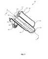
- FIG. 7is an isometric bottom view of an exemplary speculum comprising a perforated plate.
- FIG. 8is an exploded top view of the exemplary speculum of FIG. 7 .
- FIG. 9is a cross-sectional side view of the exemplary speculum of FIG. 7 taken along the line 9 - 9 ′ in FIG. 7 .
- FIG. 10is an isometric bottom view of the exemplary speculum of FIG. 7 .
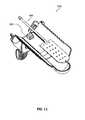
- FIG. 11is an exploded bottom view of the exemplary speculum of FIG. 7 .
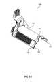
- FIG. 12is a side view of an exemplary speculum with a flared distal end.
- FIG. 13is an isometric view of the exemplary speculum of FIG. 12 .
- FIG. 14is an exploded side view of the exemplary speculum of FIG. 12 .
- FIG. 15is a view of an exemplary speculum with a flared distal end and a fluid handler.
- This disclosurerelates generally to medical surgical instruments, particularly structurally-adjustable speculums and retractors for gynecological and obstetrical examinations and procedures. These medical devices are hereafter called “minimally obstructive speculums” or “speculums.”
- the speculum ( 100 )has a proximal end and a distal end.
- the speculum ( 100 )may comprise a central body portion ( 101 ), at least two wings ( 102 , 103 ), and at least one hinge ( 104 , 105 ) that affixes at least one wing to the central body portion.
- the central body portion ( 101 ), the at least one wing ( 102 , 103 ), and the at least one hinge ( 104 , 105 )may form a canopy.
- the speculum ( 100 )may further comprise a fluid handler ( 900 ). Some examples of the fluid handler ( 900 ) are shown in FIGS. 5, 6, 10 and 11 .
- the fluid handler ( 900 )may handle any type of fluid.
- the fluidmay be gas (e.g. air), liquid (e.g. water), solid particles entrained in gas (e.g. smoke), liquid particles entrained in gas (e.g. mist), solid particles entrained in liquid, and the like.
- An example of the fluidis bodily fluid. Some examples of the bodily fluid may be blood, amniotic fluid, or mixtures thereof. Such bodily fluids may originate from uterus and/or cervix.
- the fluid handler ( 900 )may help to reduce the amount of fluids that may otherwise obscure inspection or interfere with a medical intervention. Examples of medical interventions may be obstetric and/or gynecological procedures.
- the fluid handler ( 900 )may partially or substantially remove the fluid.
- the fluid handler ( 900 )may reduce the amount of bodily fluids flowing within the vagina during medical interventions.
- the fluid handlerpartially or substantially removes smoke that may form during the medical intervention to the vagina.
- the fluid handler ( 900 )may provide fluids during the medical intervention.
- the fluid handlermay provide saline for irrigation of the vagina during the medical intervention.
- the fluid handler ( 900 )may comprise a conduit.
- the conduitmay be a tube.
- the fluid handler ( 900 )may comprise a perforated conduit.
- the fluid handlermay comprise a conduit that may comprise a non-perforated segment and a perforated segment.
- An example of the fluid handlermay comprise a tube ( 411 ) with a perforated distal end ( 412 ), as shown in FIGS. 1-6 .
- the perforated distal end ( 412 )may comprise one or more holes.
- Another example of the fluid handlermay comprise a tube ( 411 ) and a perforated plate ( 413 ), as shown in FIGS. 7-11 .
- the perforated plate ( 413 )may comprise one or more holes.
- the perforated platemay have any shape.
- the perforated platemay be curved, substantially flat, or combinations of such shapes.
- the fluid handler ( 900 )may further comprise a fluid handler port ( 410 ), which may be used to attach, for example a pump, to handle the fluids.
- the pump(not shown in the figures) may be used to remove or provide fluids, for example, to the vagina.
- the pumpmay be a vacuum pump.
- the fluid handler ( 900 )may be permanently attached to the speculum ( 100 ), as shown in FIGS. 1-4, 7-8 and 15 .
- the fluid handler ( 900 )may be temporarily attached to the speculum ( 100 ), as shown in FIGS. 5-6 and 10-11 .
- the fluid handlermay be permanently attached to the central body portion.
- the fluid handlermay be permanently attached to at least one of the wings.
- the speculum ( 100 )may further comprise a docking port to securely attach the fluid handler ( 900 ) to the speculum ( 100 ), as shown in FIG. 5 .
- the docking portmay temporarily hold the fluid handler against the speculum ( 100 ) such that the fluid handler does not obstruct the user from performing inspection or procedures upon the vaginal walls or surrounding anatomic structures.
- Examples of the docking portsmay be clips, fasteners, loops, hooks, adhesive pads, and combinations thereof.
- the fluid handler ( 900 )may be a temporarily attachable fluid handler.
- the tube ( 411 ) of the fluid handler ( 900 )may temporarily be attached or docked onto the speculum ( 100 ) by using a clip ( 505 ), as shown in FIGS. 5, 6, 10 and 11 .
- the fluid handlermay be temporarily attached to the central body portion.
- the fluid handlermay be temporarily attached to at least one of the wings.
- the speculum ( 100 )may further comprise an illumination source ( 1000 ). Examples of the speculum comprising the illumination source ( 1000 ) are shown in FIGS. 2, 8, and 14 .
- the fluid handler ( 900 )may be permanently or temporarily attached to the structure of the illumination source ( 1000 ).
- the fluid handler ( 900 )may be permanently attached to the structure of the illumination source, as shown in FIGS. 1-4, 7-8 and 15 .
- the fluid handler ( 900 )may be temporarily attached to the illumination source, as shown in FIGS. 5-6 and 10-11 , by using the features disclosed above.
- the speculum ( 100 )may comprise an illumination source ( 1000 ) and a fluid handler ( 900 ), wherein the fluid handler ( 900 ) may be permanently or temporarily the structure of the illumination source ( 1000 ).
- the fluid handler comprising a perforated conduitmay be permanently or temporarily attached to the structure of the illumination source.
- the perforated conduit comprising a non-perforated segment and a perforated segmentmay be temporarily or permanently the structure of the illumination source.
- the perforated conduit comprising a tube with a perforated distal endmay be temporarily or permanently attached to the structure of the illumination source.
- the perforated conduit comprising a tube and a perforated platemay be permanently or temporarily attached to the structure of the illumination source.
- the speculum ( 100 )may further comprise a channel.
- this channelmay have any shape and size.
- this channelmay have a concave shape.
- this channelmay be a narrow depression such as trough or gutter.
- the fluid handler ( 900 )may help to reduce amount of fluids that may obscure inspection or interfere with a medical intervention.
- the liquidsmay partially or substantially cover or flood the canopy formed by the central body portion ( 101 ), the at least one wing ( 102 , 103 ), and the at least one hinge ( 104 , 105 ). This may particularly happen when the user rotates the speculum within the vagina to medically intervene to the different vaginal surfaces.
- the channelmay aid easy removal of the liquid from the speculum and the vagina.
- the channelmay be integrated into the central body portion ( 101 ).
- the central body portion facing the liquid handler ( 900 )may have a concave shape, as shown in FIG. 3 .
- the channelmay be integrated into the fluid handler ( 900 ).
- the central body portion ( 101 ), the at least one wing ( 102 or 103 ), and the at least one hinge ( 104 or 105 )may form a canopy.
- the canopymay be formed such that the fluid flow through the exterior surface of the canopy, defined by the exterior surfaces of the body ( 101 ), wings ( 102 , 103 ) and hinges ( 104 , 105 ), is substantially blocked.
- the central body portion ( 101 )may be convex on the exterior of the speculum ( 100 ) and concave on the interior.
- the central body portion ( 101 )may be of a shape, contour, thickness, angle, radius, and size to hold up the vaginal walls during various procedures.
- the wing ( 102 , 103 )has a proximal end and a distal end.
- the wing ( 102 , 103 )also has a top adjacent to the hinge ( 104 , 105 ) and a bottom.
- the wings ( 102 , 103 )may be solid.
- These wings ( 102 , 103 )may also be hollow and shell-like to provide a convex exterior and conversely, a generally concave interior to permit visual as well as manual access thereto.
- the wings ( 102 , 103 )may be of a shape, contour, thickness, angle, radius, and size to hold up the vaginal walls during various procedures.
- the wings ( 102 , 103 )may also comprise protruded and/or thinned portions ( 120 , 121 ) to provide friction and prevent the device ( 100 ) from undesirable movement during use. These thinned portions are thinner than the remaining portions of the wing.
- the protruded and/or thinned portions ( 120 , 121 )may protrude from the wings ( 102 , 103 ) or be etched or carved into the wings.
- the protruded and/or thinned portionsmay be anywhere on the wings.
- the protruded and/or thinned portionsmay be on the edges of the wings.
- the protruded and/or thinned portionsmay comprise various shapes or forms such as grooves, serrations, cross-hatches, bumps, or other morphologies to provide adequate friction with the tissue, while not damaging the tissue or causing discomfort to the patient.
- the top portion of the central body portion ( 101 )may comprise grooves, blunted barbs, or other textures to provide friction and to resist slippage of the speculum ( 100 ) within the vaginal cavity.
- the wingscomprise serrated wing edges. This serrated wing edges may be at the bottom.
- An example of the speculum ( 100 )may comprise a so-called “living hinge”.
- the speculummay be formed as one piece, by using manufacturing techniques such as molding, machining or welding. And the thinned section of the speculum, which is relatively thinner than the central body portion and the wings, forms the living hinge. Thereby, the one-piece speculum can easily flex along the line of the living hinge.
- a hinge of this typemay be capable of many flexures over an extended period of time without the material fatiguing or breaking.
- the width of the living hingeis smaller than the width of the wing ( 102 , 103 ) and/or the central body portion ( 101 ).
- the living hinge ( 104 , 105 ) widthis substantially smaller than the width of the wing ( 102 , 103 ) and/or the central body portion ( 101 ).
- the living hinge ( 104 , 105 )is not the only speculum example that has a canopy wherein the fluid flow through the exterior surface of the canopy is substantially blocked.
- the speculum ( 100 )may be formed by substantially reducing the width of the hinge and/or the width of the gap between the central body portion ( 101 ) and the wing ( 102 , 103 ).
- the wings ( 102 , 103 )are formed to overlap on the exterior surface of the central body portion ( 101 ) or the central body portion ( 101 ) is formed to overlap on the exterior surface of the wings ( 102 , 103 ).
- the speculum ( 100 )may further comprise a substantially impermeable membrane that substantially covers the exterior and/or the interior surface of the canopy, or the exterior and/or the interior surface of the gap between the central body portion ( 101 ) and the wings ( 102 , 103 ).
- the speculum ( 100 )may further comprise at least one central body portion ( 101 ) and/or at least two wings ( 102 , 103 ) that are entirely or partially flexible such that the wings ( 102 , 103 ) may be able to move toward or away from each other by bending of the entire structure.
- the hinges ( 104 , 105 )may comprise the same or different material as the wings ( 102 , 103 ) and the central body portion ( 101 ).
- the hinges ( 104 , 105 )may permit the wings ( 102 , 103 ) to flex or pivot about the central body portion ( 101 ) such that the lower longitudinal wing edges of the speculum may be pivoted open to permit visual and manual access to the interior of a body passage.
- the exemplary speculum ( 100 )may also comprise a ratchet mechanism ( 220 ).
- This ratchet mechanism ( 220 )may serve to provide structural support to the wings ( 102 , 103 ) to counteract the force of the vaginal walls on the wings. This structural support may also prevent the hinges ( 104 , 105 ) from breaking due to the force of the vaginal walls on the wings ( 102 , 103 ).
- the ratchet mechanism ( 220 )may also serve to hold the wings ( 102 , 103 ) in various positions with respect to each other. For example, the user may desire to have the wings ( 102 , 103 ) closer to each other during insertion and removal of the speculum ( 100 ).
- Various wing positionsmay also be desired for different body shapes, sizes, or morphologies.
- the ratchet mechanism ( 220 )may comprise two ratchet arms ( 222 , 223 ). In some examples, the ratchet mechanism ( 220 ) may prevent the wings ( 102 , 103 ) from moving toward each other from the force of the vaginal walls, while in other examples the ratchet mechanism ( 220 ) may lock together to prevent the wings ( 102 , 103 ) from moving away from each other due to the configuration of the hinges ( 104 , 105 ).
- the ratchet arms ( 222 , 223 )may attach to three areas of the speculum ( 100 ): at the base of each wing's lip ( 202 , 203 ) and at the speculum limiter ( 201 ).
- the lips ( 202 , 203 )may comprise fasteners ( 255 , 256 ), which may comprise barbed pins that engage the fastener recesses ( 252 , 253 ) of the ratchet arms ( 222 , 223 ).
- the ratchet arms ( 222 , 223 )may further attach to the body of the speculum ( 100 ) by means of central ratchet hub fastener ( 230 ) protruding from the left speculum arm ( 222 ), as shown in FIG. 3 .
- the ratchet hub fastener ( 230 )may comprise barbed pins.
- the ratchet hub fastener ( 230 )may pass through a hole ( 231 ) shown in FIG. 3 .
- the ratchet hub fastener ( 230 )may also fasten to a limiter recess ( 204 ) on the proximal side of the speculum limiter ( 201 ).
- the limiter recess ( 204 )may be elongated along its vertical axis in order to allow the fastener pin ( 230 ) to slide up and down along the vertical axis of the limiter. This sliding may be necessary as the ratchet arms ( 222 , 223 ) move away from each other, since in this example the fasteners are fixed to the lips ( 202 , 203 ).
- the limiter recess ( 204 )may not be elongated, so that the fastener pin ( 230 ) would not move up or down with respect to the speculum limiter ( 201 ). Rather, the fastener recesses ( 252 , 253 ) of the ratchet arms ( 222 , 223 ) could be elongated so that the fasteners are fixed to the lips ( 202 , 203 ) and could move along the elongated fastener recesses.
- the ratchet arms ( 222 , 223 )may also comprise ratchet grasps ( 262 , 263 ).
- the ratchet grasps ( 262 , 263 )may be useful for spreading the ratchet arms away from, or closer to, each other.
- the ratchet grasps ( 262 , 263 )may also be useful for altering the position of the speculum ( 100 ), inserting the speculum, or removing the speculum.
- the ratchet grasps ( 262 , 263 )may further comprise textures, or other protruded and/or thinned portions, in order to increase friction and facilitate gripping by the user.
- One of the ratchet arms ( 222 , 223 )may comprise a ratchet release trigger that comprises a ratchet release trigger handle ( 243 ) and a ratchet tooth engager ( 242 ).
- the ratchet tooth engager ( 242 )may latch onto the ratchet teeth ( 240 ) of the other ratchet arm.
- the ratchet tooth engager ( 242 )may release from the ratchet teeth ( 240 ) when the user presses the ratchet release trigger handle ( 243 ).
- a carve-out adjacent to the ratchet teethmay serve as a ratchet limiter engaging slot ( 246 ) along which a ratchet limiter stop on the opposing ratchet arm may move as the ratchet arms move relative to each other. This may prevent the distance between the tips of the of the ratchet arms ( 222 , 223 ) from exceeding three inches. In some examples, the distance may be more than three inches, for instance about four inches. In other examples, it may be 2.5 inches or less.
- one of the ratchet arms ( 222 , 223 )may comprise two pegs ( 281 , 282 ) which are able to travel back and forth within mating grooves ( 291 , 292 ) integrated within the central body portion ( 101 ), thereby effectively restricting rotation of the speculum ( 100 ) off axis, swiveling of the central body portion ( 101 ) relative to the ratchet arms, and/or buckling of the hinges ( 104 , 105 ).
- the exemplary speculum ( 100 )may also comprise a distal tip ( 106 ), which is the first part of the speculum inserted into the body.
- the distal tip ( 106 )may be thick and wide enough to hold the upper portion of the vaginal walls during various procedures.
- the distal end of the distal tip ( 106 )may be round and smooth to provide comfort and minimize damage to the tissue during use.
- the distal tip ( 106 )may comprise only slightly concave, straight, or convex portion such that the open distal tip ( 106 ) provides a clear and open view of the cervix. This slightly concave distal tip ( 106 ) may resemble a duck-bill in shape, common to existing vaginal speculum designs.
- the distal tip ( 106 )may also comprise grooves, blunted barbs, or other textures to provide friction and to resist slippage of the speculum ( 100 ) within the vaginal cavity.
- the distal tip ( 106 )may have a slight curvature suitable to positioning in the vaginal fornices. This positioning of the distal tip ( 106 ) in the vaginal formix may help to ensure that a clear, unobstructed view of the cervix is provided.
- the speculum ( 100 )may further comprise a gripping proximal tip ( 228 ) at the proximal end.
- This gripping proximal tipmay extend from the proximal end of the central body portion ( 101 ). This gripping proximal tip may stick out of the vagina while the rest of the speculum is inserted, and thus allow the user to grab the portion to facilitate altering the position of the speculum ( 100 ), inserting the speculum, removing the speculum, or holding the speculum in place.
- This gripping proximal tipmay further comprise textures, or other protruded and/or thinned portions, in order to increase friction and facilitate gripping by the user.
- the speculum ( 100 )comprises a speculum limiter ( 201 ).
- the limiter ( 201 )may be included in the same molded part as the central body portion ( 101 ).
- the limiter ( 201 )may prevent the speculum ( 100 ) from penetrating too far into vagina, and may prevent damage to the cervix, uterus, or other parts of the female patient.
- the limiter ( 201 )may also have a smooth surface free of surface protrusions or holes in order to prevent painful interaction with the clitoris.
- the wings ( 102 , 103 )may also comprise lips ( 202 , 203 ) at their proximal ends.
- the lips ( 202 , 203 ) along with the wings ( 102 , 103 ), the central body portion ( 101 ), and the limiter ( 201 )may prevent blood, tissue, or other materials from entering the area where the suturing takes place.
- the lips ( 202 , 203 )may also help to prevent the speculum ( 100 ) from penetrating too deeply into the vagina.
- the lips ( 202 , 203 )may also increase stability of the speculum ( 100 ), and help to secure its position with respect to the vagina.
- the wings ( 102 , 103 )may flare outward along a portion of their length. In particular, distance between the opposing wings may be greater toward the end that is deeper the body cavity, and may be narrower toward the opening of the vaginal cavity. Consequently, pressure of the vaginal walls upon the length of the speculum's blades may tend to hold the speculum ( 100 ) within the cavity, thereby preventing the speculum ( 100 ) from sliding out of the vagina.
- the speculum ( 100 )may further comprise a serrated edge ( 121 ), as shown in FIGS. 1-15 .
- the serrated edge ( 121 )may prevent undesired movements, such as slippage, of the speculum ( 100 ) when it is placed in the vagina.
- the speculum ( 100 )may further comprise an illumination source ( 1000 ).
- the illumination sourcemay comprise more than one illumination devices.
- one or all device components forming the illumination sourcemay be located within the speculum limiter ( 201 ).
- a fiber optic cable or light-guidemay direct the light to one or more sites where the light is emitted.
- the fiber optic cable or light-guidemay refract the light for focused or diffuse emission.
- one or all device components forming the illumination sourcemay be located within the canopy formed by the speculum ( 100 ).
- the illumination source ( 1000 )may comprise a light-emitting diode wherein the light emitting diode may be located within the speculum canopy.
- the whole illumination sourceis located within the speculum canopy. In such examples, a compact speculum ( 100 ) with no illumination source components dangling beyond the other speculum parts may be obtained.
- the illumination source ( 1000 )may comprise a light, such as battery-powered light-emitting diode (LED), located within a light source housing.
- the light source housingmay be attached to a cap (not shown) that attaches to the speculum limiter ( 201 ).
- the capmay attach to the limiter by means of a fastener, comprising a pin, which connects to either a ratchet arm ( 222 , 223 ) or the speculum limiter ( 201 ).
- the capdoes not have a fastener; rather it may attach by means of an adhesive.
- the light source housingmay swivel.
- the usermay manually operate the light function externally via a mechanical switch, while in another examples, the light function may be turned on and off automatically.
- the usermay control the brightness of the light. In one example, the user may control the brightness of the light by means of a switch, button, or dial.
- the illumination source ( 1000 )may comprise a plurality of light emitting components such as light emitting diodes (LEDs) ( 400 ) capable of producing sufficient visible light to view the area of interest, a power supply such as coin cell batteries ( 295 ) to drive the LED ( 400 ), power management components such as resistors, and reed sensor switch ( 294 ) to activate the LED ( 400 ).
- the LED ( 400 ), resistors, reed switch ( 294 ) and power supply batteries ( 295 )may be assembled on a printed circuit board ( 299 ), also known as a PCB.
- the lightmay be emitted by electroluminescent or chemiluminescent material.
- the illumination sourcemay be automatically turned on and off in conjunction with movement of the ratchet arms ( 222 , 223 ) away from, and towards, each other, respectively.
- the LEDmay be turned on and off via a reed sensor switch ( 294 ).
- the reed sensor switch ( 294 )may be turned on in the presence of a magnetic field generated by a magnet ( 293 ), and may turn off in the absence of the magnetic field generated by the magnet.
- the reed sensor switch ( 294 )may be sensitive to the position of the magnet ( 293 ).
- the magnet ( 293 )may be installed within a magnet seat ( 244 ), which may be located in one of the ratchet arms ( 222 , 223 ).
- the coin cell batteries ( 295 )may be connected using contact wires or directly assembled onto the printed circuit board ( 299 ). Alternatively, the electronic components may be brought in contact to complete the circuit without soldering and connected by compression of the assembly packaging.
- the LED assemblymay be placed onto a plurality of mounting posts ( 297 ) on an LED cover ( 298 ), which may comprise a translucent material, and assembled into mating features (not shown) located on the underside of the central body portion ( 101 ).
- a gasket ( 301 ) made of rubber or other materials,may be placed between the LED cover ( 298 ) and an inner surface of the central body portion ( 101 ) to prevent or minimize the ingress of fluids and dirt into the LED assembly.
- the gasket ( 301 )may prevent chemicals from leaking outside the speculum ( 100 ), thereby protecting the user.
- the gasket ( 301 )may be held in place by mating features in the main body surface, by adhesive, or by other means.
- the LED covers ( 298 ) and LED assemblymay also be mated with the main body via other fastening mechanisms such as screws or epoxy.
- the stemmay travel in a vertical path inside a slot located with the LED cover ( 298 ), thereby making the actuation mechanism hidden from to the user.
- the magnet ( 293 )may be embedded within or attached to one of the ratchet arms ( 222 , 223 ).
- the mechanism of turning the light on and offmay comprise a mechanical push button switch.
- the switchmay be placed behind the ratchet arms at a location where the arms interact with each other. When the ratchet arms are opened outward and pass over each other, the switch may be triggered, thus completing the electrical circuit and turning on the light.
- the mechanical push button switchmay be placed between surfaces of the ratchet arms where the mechanical push switch button may by pressed in the off position when the ratchet arms ( 222 , 223 ) are closed, thus keeping the light function off.
- the ratchet arms ( 222 , 223 )are opened outwardly, this may release the switch, thereby turning the switch to the on position, completing the electrical circuit and turning the light function on.
- the mechanical push button switchmay be accessible to the user to manually turn the light function on or off.
- the switchmay be located on the ratchet arm hub for easy access.
- an optical sensor switchmay be used to activate the light function.
- the switchmay be placed in the main body or ratchet arm and between the surfaces thereby occluding the sensor of the switch from ambient light.
- the ratchet arms222 , 223
- the switchturns the light function on.
- a breakoff plastic featuremay be used to trigger a switch (or an incomplete circuit by a separated wire connection) to turn on the light.
- one of the ratchet arms ( 222 , 223 )may be connected to the switch via a plastic feature or tab.
- this plastic tabcould break, consequently activating the switch (or completing the connection between the separated wire) to turn on the light.
- the device light functioncould stay on until the batteries are drained of their power.
- a variation of this mechanismmay use the plastic tab as a cover over the optical sensor switch. On pulling the ratchet arms outwardly, the plastic tab could break and expose the optical sensor, thereby completing the electrical circuit and turning the light on.
- the devicemay comprise a plurality of LEDs located at various portions of the interior of the device.
- the LEDsmay be located on or integrated within the interior surfaces of the central body portion ( 101 ), the distal tip ( 106 ), and/or the wings ( 102 , 103 ).
- the speculum ( 100 )may comprise only two wings ( 102 , 103 ) and only one central body portion ( 101 ). That is, the speculum may not have more than two wings and may not have more than one central body portion.
- the speculum ( 100 )may be manufactured from a material that may comprise a polymer such as acrylonitrile butadiene styrene (ABS), polyurethane, acetal plastics, or another material known to those skilled in the art that provides both structural rigidity and flexibility.
- This materialmay also comprise flexible plastic material such as polyamide sold under the trade name “Nylon,” polytetrafluoroethylene sold under the trademark “Teflon”.
- a polypropylene plastic or a high density polyethylene plasticmay be used to manufacture the speculum ( 100 ).
- the speculum ( 100 )may be made of a transparent plastic in order to enhance the viewing area. It may also be made of metal. Mixtures or composites of these materials may also be used to manufacture the speculum ( 100 ).
- the hinge ( 104 , 105 )may be manufactured from a material that may comprise a polymer.
- the hingefor example, may be made from a material comprising polyethylene, polypropylene, nylon, acetal plastics or mixtures thereof. In another example, the hinge material may even be manufactured from a material comprising polyethylene, polypropylene or mixtures thereof.
- the speculum ( 100 )may be sterilizable by ethylene oxide, gamma radiation or other process known to those skilled in the art. It may be disposable or reprocessable. Also, the speculum ( 100 ) may be made of different sizes and/or thicknesses to accommodate different ages and sizes of patients. The speculum ( 100 ) may be coated with a material to facilitate inspection and movement. For example, a lubricant can be used to coat the speculum ( 100 ) to facilitate insertion and retrieval.
- a significant portion of the speculum ( 100 )may be formed from a single continuous material. That is, the speculum—is formed from only one component.
- the speculummay be manufactured by molding.
- the central body portion ( 101 ), wings ( 102 , 103 ), and distal tip ( 106 )may be injection molded to form a single component.
- An exemplary material for injection moldingmay be polypropylene.
- the speculum ( 100 )may be sized to fit vaginas of different size ranges. In other examples, the speculum ( 100 ) may be sized to fit larger vaginas. In some examples, the speculum's dimensions and contours may accommodate the excess tissue of overweight and obese patients. These variations may consist of differences in any of a variety of dimensions of the speculum and its features, such as the overall length of the speculum ( 100 ); the length and/or width of the central body portion ( 101 ); and/or the span, length, shape, and/or morphology of the wings ( 102 , 103 ).
- the speculum ( 100 )may be used in various procedures, including episiotomy repair, repair of vaginal lacerations, and visualization during checkups.
- the ratchet mechanismmay be adjusted to hold the wings ( 102 , 103 ) in various positions with respect to each other.
- the usermay desire to have the wings ( 102 , 103 ) closer to each other during insertion and removal of the speculum ( 100 ), while keeping the wings ( 102 , 103 ) farther apart from each other to maximize the viewing and working fields during procedures.
- Various positionsmay also be desired for different body shapes, sizes, or morphologies. The position of the wings may be changed during procedures using the ratchet mechanism.
- the speculum ( 100 )may be used for improved visualization, access, and repair in various procedures, including, but not limited to: obstetrical/gynecological procedures: vaginal inspection; perineal inspection; vaginal wound repair; perineal wound repair; episiotomy repair; female pelvic exam; pap smear; cervical biopsy; vaginal/pelvic reconstruction; urological procedures; colorectal, general, or other surgery; the speculum ( 100 ) may be turned upside-down, for example, for female urologic procedures; access to the cervix (or uterus via cervix); IUD insertion, removal, or adjustment; colposcopy, speculoscopy, and dilatation & curettage (dilatation of cervix and curettage of uterus).
- a vaginal lacerationtypically has its apex nearer the cervix and become wider toward the introitus.
- the usermay begin suturing a vaginal laceration with the speculum ( 100 ) deployed in the vagina in its open position, with the speculum ( 100 )'s wings ( 102 , 103 ) spread apart.
- the sutureis typically started at the apex of a tear deeper in the vagina, nearer the vaginal vault or cervix.
- the usermay adjust the speculum ( 100 ) to a more closed position, with its wings ( 102 , 103 ) closer to each other. This may ease the approximation of tissue from opposing sides of the laceration. Intermittent, slight closing of the speculum ( 100 ) as the suturing is performed may allow the user to achieve the appropriate degree of retraction throughout the run of the suture, until the suturing is complete.
- the speculum ( 100 ) and the system ( 800 )may be used in a variety of medical and surgical procedures including vaginal and perineal wound repair, episiotomy repair, pelvic floor repair and/or reconstruction, and/or cosmetic gynecology procedures.
- the speculum ( 100 )may comprise a plurality of LEDs located at various portions of the interior of the device.
- the LEDsmay be located on or integrated within the interior surfaces of the central body portion ( 101 ), the distal tip ( 106 ), and/or the wings ( 102 , 103 ).
- the speculum ( 100 )may comprise LEDs of different colors, with a switch mechanism that allows the user to switch between different colors of illumination.
- the speculum ( 100 )may comprise one or more colored transparent/translucent material swatches or lenses that the user may move into or out of the path of the light.
- this color switching mechanismmay comprise a spinnable wheel with differently colored segments, a slidable window with differently colored segments, or insertable and removable panels of different colors.
- the speculummay allow the user to control different settings of illumination, which may include white light, green light, different brightnesses of light, and no light.
- the speculummay comprise a magnifying lens.
- the magnifying lensmay be integrated with the body of the device, or may be a separate attachment.
- the reservoirmay be located on, or integrated within, the proximal end of the central body portion ( 101 ) and/or the wings ( 102 , 103 ).
- the magnifying lensmay further comprise a latch for user to apply or remove it from the device, or a sliding mechanism for moving the magnifying lens into or out of view.
- the magnifying lensmay provide the user with a magnified view of the cervix or other anatomic, pathologic, or other structures.
- FIGS. 12-15depict various views of other exemplary specula ( 100 ).
- This speculummay be used as a retractor for the surgical incisions.
- the central body portion ( 101 ) and/or wings ( 103 )may flare inward along a portion of their length. In particular, distance between the opposing wings may be narrowed toward the middle of the wings.
- the proximal and/or distal ends of the central body portion and/or wingsmay flare outward.
- the distal ends of the central body portion and/or wingsmay have protrusions, such as ridges, on their exterior surfaces. In the exemplary speculums shown in FIGS.
- the central body portioncomprises a ridge ( 141 ) at its distal end
- the wingscomprise ridges ( 142 , 143 ) at their distal ends. Consequently, pressure of the retracted tissue layers upon the length of the device's central body portion and/or wings, on the narrower segments between the flares or protrusions at their distal an/or proximal ends, may tend to hold the speculum within the surgical opening, thereby preventing the device from sliding out of the surgical opening.
- the devicewould effectively grasp the incised tissue layers in a manner similarly to a split grommet securely spanning a hole in a membrane.
- the speculummay further comprise a fluid handler as shown in FIG. 15 .
- the exemplary specula shown in FIGS. 12-15may be used for improved visualization, access, and repair in various procedures, including, but not limited to: obstetrical/gynecological, urological procedures, colorectal, general, or other surgery.
- the devicemay be used in: tubal ligation; salpingo oophorectomy; thyroidectomy; video-assisted thoracoscopic surgery; thoracotomy; appendectomy; myomectomy; lap colectomy; colposcopy, speculoscopy, and mini-laparotomy.
- the speculum ( 100 )may comprise a central body portion, at least two wings, at least two hinges that affix the at least two wings to the central body portion, and a fluid handler; wherein the fluid handler is a temporarily attachable fluid handler, and wherein the docking port may be used to attach the temporarily attachable fluid handler to the speculum; wherein the fluid handler comprises a perforated conduit, and wherein the perforated conduit comprises a non-perforated segment and a perforated segment.
- the speculum ( 100 )may comprise a central body portion, at least two wings, at least two hinges that affix the at least two wings to the central body portion, and a fluid handler; wherein the fluid handler is a temporarily attachable fluid handler; and wherein the docking port may be used to attach the temporarily attachable fluid handler to the speculum; wherein the fluid handler comprises a perforated conduit; wherein the perforated conduit comprises a non-perforated segment and a perforated segment; and wherein the speculum further comprises a channel integrated with the central body portion.
Landscapes
- Health & Medical Sciences (AREA)
- Life Sciences & Earth Sciences (AREA)
- Surgery (AREA)
- Veterinary Medicine (AREA)
- Molecular Biology (AREA)
- Nuclear Medicine, Radiotherapy & Molecular Imaging (AREA)
- Public Health (AREA)
- General Health & Medical Sciences (AREA)
- Animal Behavior & Ethology (AREA)
- Engineering & Computer Science (AREA)
- Biomedical Technology (AREA)
- Heart & Thoracic Surgery (AREA)
- Medical Informatics (AREA)
- Reproductive Health (AREA)
- Physics & Mathematics (AREA)
- Biophysics (AREA)
- Radiology & Medical Imaging (AREA)
- Pathology (AREA)
- Optics & Photonics (AREA)
- Vascular Medicine (AREA)
- Gynecology & Obstetrics (AREA)
- Pregnancy & Childbirth (AREA)
- Rehabilitation Therapy (AREA)
- Surgical Instruments (AREA)
Abstract
Description
Claims (21)
Priority Applications (1)
| Application Number | Priority Date | Filing Date | Title |
|---|---|---|---|
| US14/468,210US9861349B2 (en) | 2011-09-29 | 2014-08-25 | Speculum for obstetrical and gynecological exams and related procedures |
Applications Claiming Priority (6)
| Application Number | Priority Date | Filing Date | Title |
|---|---|---|---|
| US13/248,928US9050048B2 (en) | 2010-09-29 | 2011-09-29 | Minimally obstructive retractor |
| US201361871229P | 2013-08-28 | 2013-08-28 | |
| US201361871233P | 2013-08-28 | 2013-08-28 | |
| US201361871222P | 2013-08-28 | 2013-08-28 | |
| US14/468,210US9861349B2 (en) | 2011-09-29 | 2014-08-25 | Speculum for obstetrical and gynecological exams and related procedures |
| PCT/US2014/052573WO2015031282A1 (en) | 2013-08-28 | 2014-08-25 | Minimally obstructive retractor for vaginal repairs |
Related Parent Applications (1)
| Application Number | Title | Priority Date | Filing Date |
|---|---|---|---|
| US13/248,928Continuation-In-PartUS9050048B2 (en) | 2010-09-29 | 2011-09-29 | Minimally obstructive retractor |
Publications (2)
| Publication Number | Publication Date |
|---|---|
| US20140364695A1 US20140364695A1 (en) | 2014-12-11 |
| US9861349B2true US9861349B2 (en) | 2018-01-09 |
Family
ID=58266754
Family Applications (2)
| Application Number | Title | Priority Date | Filing Date |
|---|---|---|---|
| US14/468,210Active - Reinstated2033-04-02US9861349B2 (en) | 2011-09-29 | 2014-08-25 | Speculum for obstetrical and gynecological exams and related procedures |
| US14/468,167Active2032-11-27US9907544B2 (en) | 2011-09-29 | 2014-08-25 | Minimally obstructive retractor for vaginal repairs |
Family Applications After (1)
| Application Number | Title | Priority Date | Filing Date |
|---|---|---|---|
| US14/468,167Active2032-11-27US9907544B2 (en) | 2011-09-29 | 2014-08-25 | Minimally obstructive retractor for vaginal repairs |
Country Status (5)
| Country | Link |
|---|---|
| US (2) | US9861349B2 (en) |
| EP (1) | EP3038543A4 (en) |
| CN (1) | CN105578971A (en) |
| MX (1) | MX2016002536A (en) |
| WO (1) | WO2015031282A1 (en) |
Cited By (20)
| Publication number | Priority date | Publication date | Assignee | Title |
|---|---|---|---|---|
| US9913577B2 (en) | 2010-09-28 | 2018-03-13 | Obp Medical Corporation | Speculum |
| US20190104932A1 (en)* | 2017-10-11 | 2019-04-11 | Csaba Truckai | Endoscope and method of use |
| US10278572B1 (en) | 2017-10-19 | 2019-05-07 | Obp Medical Corporation | Speculum |
| US20190223708A1 (en)* | 2018-01-25 | 2019-07-25 | Maurice Andre Recanati | Vaginal speculum and side wall retractor |
| US10420538B2 (en) | 2015-02-05 | 2019-09-24 | Obp Medical Corporation | Illuminated surgical retractor |
| US10420540B2 (en) | 2015-02-05 | 2019-09-24 | Obp Medical Corporation | Illuminated surgical retractor |
| US10512519B2 (en) | 2018-02-20 | 2019-12-24 | Obp Medical Corporation | Illuminated medical devices |
| US10687793B2 (en) | 2017-07-18 | 2020-06-23 | Obp Medical Corporation | Minimally invasive no touch (MINT) procedure for harvesting the great saphenous vein (GSV) and venous hydrodissector and retractor for use during the MINT procedure |
| US10722621B2 (en) | 2016-07-11 | 2020-07-28 | Obp Medical Corporation | Illuminated suction device |
| US10799229B2 (en) | 2018-02-20 | 2020-10-13 | Obp Medical Corporation | Illuminated medical devices |
| USD904607S1 (en) | 2019-05-07 | 2020-12-08 | Obp Medical Corporation | Nasal retractor |
| US10881387B2 (en) | 2015-06-03 | 2021-01-05 | Obp Medical Corporation | Retractor |
| USD911521S1 (en) | 2019-02-19 | 2021-02-23 | Obp Medical Corporation | Handle for medical devices including surgical retractors |
| US10939899B2 (en) | 2015-06-03 | 2021-03-09 | Obp Medical Corporation | End cap assembly for retractor and other medical devices |
| US10952712B2 (en) | 2015-06-03 | 2021-03-23 | Obp Medical Corporation | Retractor |
| US10959609B1 (en) | 2020-01-31 | 2021-03-30 | Obp Medical Corporation | Illuminated suction device |
| US10966702B1 (en) | 2020-02-25 | 2021-04-06 | Obp Medical Corporation | Illuminated dual-blade retractor |
| US20210315450A1 (en)* | 2020-04-11 | 2021-10-14 | Dan Kort | Vaginal speculum and system |
| US12156640B2 (en) | 2017-10-11 | 2024-12-03 | Meditrina, Inc. | Endoscope and method of use |
| US12318080B2 (en) | 2023-07-21 | 2025-06-03 | Coopersurgical, Inc. | Illuminated surgical retractor capable of hand-held operation and of being mounted to a fixed frame |
Families Citing this family (21)
| Publication number | Priority date | Publication date | Assignee | Title |
|---|---|---|---|---|
| US9861349B2 (en) | 2011-09-29 | 2018-01-09 | Proa Medical, Inc. | Speculum for obstetrical and gynecological exams and related procedures |
| WO2015138317A1 (en) | 2014-03-10 | 2015-09-17 | Stryker Corporation | Limb positioning system |
| CN106714661A (en)* | 2014-08-03 | 2017-05-24 | 南加州大学阿尔弗雷德·E·曼生物医学工程研究所 | Minimally obstructive compact speculum |
| US9951904B2 (en) | 2015-03-24 | 2018-04-24 | Stryker Corporation | Rotatable seat clamps for rail clamp |
| US11259785B2 (en) | 2016-09-16 | 2022-03-01 | Lida Aghdam | Vagina probe with brush |
| AU2018323022A1 (en)* | 2017-08-31 | 2020-04-09 | The Insides Company Limited | Improved medical device |
| US20200275831A1 (en)* | 2017-09-11 | 2020-09-03 | Progressive Innovations, Llc | Lighted specula, related kits, and methods for using the same |
| EP4223210A1 (en) | 2017-11-10 | 2023-08-09 | Hegenbergerspeculum APS | Device |
| CN108158620A (en)* | 2017-11-30 | 2018-06-15 | 许静 | A kind of gynemetrics's hemostasis device |
| WO2019236027A2 (en)* | 2018-02-21 | 2019-12-12 | Orhan Seyfi Aksakal | A retractor system |
| CN108324235A (en)* | 2018-03-01 | 2018-07-27 | 韩晓莉 | A kind of vaginal dilator used on gynecological nursing |
| WO2020033962A1 (en) | 2018-08-10 | 2020-02-13 | Sudabeh Moein | One-time use expandable speculum |
| US11026671B2 (en) | 2019-03-15 | 2021-06-08 | Modern Surgical Solutions, Llc | Retractor for vaginal repair |
| EP3941369A1 (en)* | 2019-03-19 | 2022-01-26 | Atropos Limited | Curette and use thereof |
| GB201906562D0 (en) | 2019-05-09 | 2019-06-26 | Hegenbergerspeculum Aps | Devices |
| CN110693452A (en)* | 2019-11-21 | 2020-01-17 | 南京普派医疗科技有限公司 | Adjustable anus operation platform |
| AU2022325511A1 (en)* | 2021-08-10 | 2024-02-29 | Sure Retractors Ltd | Retractors |
| CN113456008B (en)* | 2021-08-10 | 2025-02-18 | 苏州桑田医疗科技有限公司 | Dilation structure and four-wing vaginal dilator |
| US20230136044A1 (en)* | 2021-10-29 | 2023-05-04 | Infinity Research Inc. | Imaging speculum for otology |
| US20230337896A1 (en)* | 2022-04-25 | 2023-10-26 | The Government Of The United States As Represented By The Secretary Of The Army | Fenestrated suction retractor |
| US20240197310A1 (en)* | 2022-12-14 | 2024-06-20 | Thompson Surgical Instruments, Inc. | Surgical retractor with integrated handle and system |
Citations (158)
| Publication number | Priority date | Publication date | Assignee | Title |
|---|---|---|---|---|
| SU167005A1 (en) | Астафьев, М. Г. Козина , Л. Л. Дорфман | DEVELOPER FOR OPERATION ON BILIARY TRACKS | ||
| US55511A (en) | 1866-06-12 | Improvement in speculums | ||
| US361087A (en) | 1887-04-12 | John p | ||
| US424140A (en) | 1890-03-25 | Anal speculum | ||
| US469351A (en) | 1892-02-23 | Speculum | ||
| US583932A (en) | 1897-06-08 | Eegtal | ||
| US639444A (en) | 1896-01-18 | 1899-12-19 | Actien Ges Fuer Fein Mechanic Vormals Ietter & Scheerer | Speculum. |
| US688935A (en) | 1899-03-13 | 1901-12-17 | Sylvanus B Crane | Apparatus for examining cavities in the human body. |
| US761821A (en) | 1904-01-27 | 1904-06-07 | William H Clark | Rimless trivalve vaginal speculum. |
| US786457A (en) | 1904-04-29 | 1905-04-04 | Frank Mcginnis | Speculum. |
| US810675A (en) | 1905-04-24 | 1906-01-23 | Gustav F Richter | Dilator. |
| US847542A (en) | 1906-06-16 | 1907-03-19 | Frederick Dittmar | Hinge for surgical and other instruments. |
| US977489A (en) | 1909-08-03 | 1910-12-06 | Victor Von Unruh | Speculum. |
| US1014799A (en) | 1910-09-16 | 1912-01-16 | Richard S Arthur | Surgical instrument. |
| US2012597A (en) | 1934-06-15 | 1935-08-27 | William J Cameron | Nasal and aural speculum |
| US2374863A (en) | 1943-05-07 | 1945-05-01 | Guttmann Eugen | Vaginal speculum |
| US3176682A (en) | 1963-03-18 | 1965-04-06 | David J Wexler | Self-retaining vaginal surgical retractor |
| US3736919A (en) | 1971-09-13 | 1973-06-05 | Medspecs Inc | Speculum latching mechanism |
| US3745992A (en) | 1971-08-12 | 1973-07-17 | Medspecs Inc | Speculum |
| US3774596A (en) | 1971-06-29 | 1973-11-27 | G Cook | Compliable cavity speculum |
| US3789829A (en) | 1971-06-01 | 1974-02-05 | H Hasson | Vaginal radium applicator |
| US3796214A (en) | 1972-12-04 | 1974-03-12 | R Davis | Perineal retractor |
| US4130113A (en) | 1976-12-15 | 1978-12-19 | Richards Manufacturing Co., Inc. | Retractor |
| US4156424A (en) | 1978-05-01 | 1979-05-29 | Burgin Kermit H | Locking adjustable speculum |
| US4263898A (en) | 1977-06-22 | 1981-04-28 | Wannag Arne T | Vaginal speculum |
| US4300541A (en) | 1979-02-09 | 1981-11-17 | Kermit Burgin | Speculum lens structure |
| US4447227A (en) | 1982-06-09 | 1984-05-08 | Endoscopy Surgical Systems, Inc. | Multi-purpose medical devices |
| US4754746A (en) | 1986-09-25 | 1988-07-05 | Cox Kenneth L | Self-retaining metatarsal spreader |
| US4807600A (en) | 1986-10-15 | 1989-02-28 | Hayes Allen L | Speculum protector |
| SU1509048A1 (en) | 1988-02-03 | 1989-09-23 | С. А. Попов | Rectal speculum |
| US4971036A (en) | 1987-12-04 | 1990-11-20 | Collins Jason H | Vaginal speculum |
| US5081983A (en) | 1990-02-20 | 1992-01-21 | Villalta Josue J | Medical retractor device |
| US5183032A (en) | 1990-02-20 | 1993-02-02 | Villalta Josue J | Medical retractor device |
| US5209754A (en) | 1992-04-02 | 1993-05-11 | Ahluwalia Prabhat K | Vaginal cervical retractor elevator |
| US5439476A (en) | 1993-02-04 | 1995-08-08 | Trigonon, Inc. | Inflatable laparoscopic retractor |
| US5465709A (en) | 1993-11-10 | 1995-11-14 | Advanced Medical Products Inc. | Illuminated vaginal speculum |
| US5509893A (en) | 1991-06-06 | 1996-04-23 | Meditech International Pty Ltd. | Speculum |
| USRE35312E (en) | 1991-03-25 | 1996-08-06 | Surgical Inventions & Innovations, Inc. | Christoudias endospongestick probe |
| US5613950A (en) | 1988-07-22 | 1997-03-25 | Yoon; Inbae | Multifunctional manipulating instrument for various surgical procedures |
| US5626129A (en) | 1993-04-02 | 1997-05-06 | Josef Klimm | Device for monitoring at least one connection in a medical tubing system |
| US5643285A (en) | 1994-10-18 | 1997-07-01 | Blairden Precision Instruments, Inc. | Vaginal extender for colpotomy surgery |
| US5785648A (en) | 1996-10-09 | 1998-07-28 | David Min, M.D., Inc. | Speculum |
| US5792044A (en) | 1996-03-22 | 1998-08-11 | Danek Medical, Inc. | Devices and methods for percutaneous surgery |
| US5800394A (en) | 1988-07-22 | 1998-09-01 | Yoon; Inbae | Method of creating an operating space endoscopically at an obstructed site |
| US5868668A (en) | 1998-07-15 | 1999-02-09 | Weiss; Sol | Surgical instrument |
| US5894843A (en) | 1996-02-20 | 1999-04-20 | Cardiothoracic Systems, Inc. | Surgical method for stabilizing the beating heart during coronary artery bypass graft surgery |
| US5931777A (en) | 1998-03-11 | 1999-08-03 | Sava; Gerard A. | Tissue retractor and method for use |
| US5944736A (en) | 1996-02-20 | 1999-08-31 | Cardiothoracic Systems, Inc. | Access platform for internal mammary dissection |
| US5984350A (en) | 1997-09-22 | 1999-11-16 | Am-Safe, Inc. | Vehicle safety system |
| DE19828099A1 (en) | 1998-06-24 | 1999-12-30 | Rudolf Gmbh Medizintechnik | Surgical instrument, especially rectuscope or trocar |
| US6024697A (en) | 1999-01-11 | 2000-02-15 | Pisarik; Paul | Multi-bladed speculum for dilating a body cavity |
| US6024696A (en) | 1998-04-24 | 2000-02-15 | Hoftman; Moshe | Side wall support speculum |
| US6048308A (en) | 1999-03-30 | 2000-04-11 | Strong; John E. | Vaginal speculum |
| US6096046A (en) | 1998-06-24 | 2000-08-01 | Weiss; Sol | Surgical instrument |
| US6196969B1 (en) | 1999-05-21 | 2001-03-06 | Lab Engineering & Manufacturing, Inc. | Tissue retractor adapted for the attachment of an auxiliary element |
| US6265984B1 (en) | 1999-08-09 | 2001-07-24 | Carl Joseph Molinaroli | Light emitting diode display device |
| US6280379B1 (en) | 1999-12-02 | 2001-08-28 | Scott Resnick | Speculum |
| US6302842B1 (en) | 2001-01-11 | 2001-10-16 | Innovative Surgical Design Llc | Episiotomy retractor |
| US6312377B1 (en) | 2000-04-06 | 2001-11-06 | Viamedics, Llc | Soft tissue compression shield and method of retracting tissue |
| US6346074B1 (en) | 1993-02-22 | 2002-02-12 | Heartport, Inc. | Devices for less invasive intracardiac interventions |
| US6364832B1 (en) | 1999-12-23 | 2002-04-02 | Tri-State Hospital Supply Corporation | Vaginal lateral walls retractor for use in combination with vaginal specula and method of performing vaginal/cervical examination |
| US6395012B1 (en) | 2000-05-04 | 2002-05-28 | Inbae Yoon | Apparatus and method for delivering and deploying an expandable body member in a uterine cavity |
| US6416467B1 (en) | 2000-09-15 | 2002-07-09 | Mcmillin Matthew | Vaginal speculum and method of using same |
| US6432048B1 (en) | 1998-06-24 | 2002-08-13 | University Of South Florida | Lateral wall retractor vaginal speculum |
| US6450952B1 (en) | 1998-04-23 | 2002-09-17 | Scimed Life Systems, Inc. | Medical body access device |
| US20020156350A1 (en) | 2001-02-27 | 2002-10-24 | German Nieto | Disposable speculum with included light and mechanisms for examination and gynecological surgery |
| US6492963B1 (en) | 1998-12-07 | 2002-12-10 | Illumination Design Works | Electronic display apparatus |
| US6589168B2 (en) | 1996-02-07 | 2003-07-08 | Robert Lee Thompson | Video gynecological examination apparatus |
| US6599292B1 (en) | 1998-01-05 | 2003-07-29 | Tegementa, L.L.C. | Distraction device for vertebral disc procedures and method of distracting |
| US20030171656A1 (en) | 2002-01-22 | 2003-09-11 | Foulkes Richard B. | Ophthalmic sulcus speculum |
| US20030225313A1 (en) | 2002-06-04 | 2003-12-04 | German Borodulin | Vaginal speculum with insertable one-lens colposcope |
| US20040002629A1 (en) | 2002-06-26 | 2004-01-01 | Branch Charles L. | Instruments and methods for minimally invasive tissue retraction and surgery |
| WO2004002322A1 (en) | 2002-06-28 | 2004-01-08 | Noir Epouse Kirsch Frederique | Self-retaining retractor for perineal surgery |
| US6740031B2 (en) | 1998-07-10 | 2004-05-25 | Hier-Spec, Inc. | Speculum |
| US20040116777A1 (en) | 2002-12-13 | 2004-06-17 | Jeffrey Larson | Guided retractor and methods of use |
| WO2004098416A2 (en) | 2003-05-09 | 2004-11-18 | Bernard Ruane | Expandable and pivotally adjustable surgical retractor |
| WO2005016131A2 (en) | 2003-08-14 | 2005-02-24 | Hfsc Company | Multiple-blade retractor |
| US20050113644A1 (en) | 2003-01-06 | 2005-05-26 | Obenchain Theodore G. | Four-blade surgical speculum |
| US20050215862A1 (en) | 2003-11-26 | 2005-09-29 | Jeffrey Larson | Guided retractor and methods of use |
| US20050234304A1 (en) | 2002-06-26 | 2005-10-20 | Sdgi Holdings, Inc. | Instruments and methods for minimally invasive tissue retraction and surgery |
| US20060004261A1 (en) | 2004-06-30 | 2006-01-05 | Ethicon Incorporated | Low profile surgical retractor |
| US20060074278A1 (en) | 2004-09-02 | 2006-04-06 | Dominique Petit | Tissue retractor producing a widened operating channel |
| US7060029B1 (en) | 2004-04-14 | 2006-06-13 | Zoya, Inc. | Speculum with attachable blades for lateral wall retraction |
| US7070561B1 (en)* | 2003-12-26 | 2006-07-04 | Amir Ansari | Adjustable weighted vaginal speculum |
| US20060155170A1 (en) | 2002-12-13 | 2006-07-13 | Synthes Spine Company, Lp | Guided retractor and methods of use |
| WO2006107878A2 (en) | 2005-04-01 | 2006-10-12 | Welch Allyn, Inc. | Illumination assembly for use with vaginal speculum apparatus |
| US20060235279A1 (en) | 2005-03-18 | 2006-10-19 | Hawkes David T | Less invasive access port system and method for using the same |
| US20070027364A1 (en) | 2005-07-28 | 2007-02-01 | Stefan Schwer | Expandable access device |
| WO2007075903A2 (en) | 2005-12-27 | 2007-07-05 | East Carolina University | Endoscopic cardiac retractors with folding components configured for insertion using minimally invasive access ports and related methods |
| US7248038B2 (en) | 2003-11-26 | 2007-07-24 | Hubner Electromaschinen Gmbh | Device for the detection of movements and/or positions of an object |
| US20070208227A1 (en) | 2002-07-11 | 2007-09-06 | Nuvasive, Inc. | Surgical access system and related methods |
| US20070219416A1 (en) | 2006-03-16 | 2007-09-20 | Perez-Cruet Mick J | Minimally invasive surgical access device |
| US20080058604A1 (en) | 2006-08-31 | 2008-03-06 | Bradford Tyler Sorensen | Childbirth labor reduction device |
| US20080091080A1 (en) | 2003-04-22 | 2008-04-17 | Patrick Leahy | Device and Method for Use in Surgery |
| US20080214898A1 (en) | 2006-10-31 | 2008-09-04 | Lanx, Llc | Retractor system |
| US20080245371A1 (en) | 2007-04-06 | 2008-10-09 | William Harwick Gruber | Systems, methods and devices for performing gynecological procedures |
| CN101287404A (en) | 2005-04-01 | 2008-10-15 | 韦尔奇阿林公司 | Illumination assembly for use with vaginal speculum apparatus |
| US20080306345A1 (en) | 2005-09-29 | 2008-12-11 | Forth Photonics Limited | Vaginal Speculum Arrangement |
| US20090062042A1 (en) | 2007-08-27 | 2009-03-05 | Richard Huang | Lighted nock for archery arrow |
| US20090076334A1 (en) | 2007-09-19 | 2009-03-19 | Tien-Sheng Chen | Illuminated Vaginal Speculum and Illumination Device |
| US20090099422A1 (en) | 2004-12-15 | 2009-04-16 | Samuel George | Specula |
| CN101433452A (en) | 2007-03-20 | 2009-05-20 | 上海林静医疗器械有限公司 | Vaginal dilator with illumination device |
| US20090198108A1 (en) | 2008-01-31 | 2009-08-06 | Tien-Sheng Chen | Cervix Examination Device and Cervix Examination Set |
| WO2009099543A2 (en) | 2008-02-06 | 2009-08-13 | The University Of Vermont And State Agriculture College | Device for perineal massage and method of use |
| US7594888B2 (en) | 2004-10-29 | 2009-09-29 | Depuy Spine, Inc. | Expandable ports and methods for minimally invasive surgery |
| US20090259109A1 (en) | 2008-01-18 | 2009-10-15 | Elenor S.R.L. | Sternum retractor device |
| US20090265941A1 (en) | 2008-04-24 | 2009-10-29 | Cook Incorporated | Shaping device |
| US20090318914A1 (en) | 2008-06-18 | 2009-12-24 | Utley David S | System and method for ablational treatment of uterine cervical neoplasia |
| US20090326331A1 (en)* | 2008-06-25 | 2009-12-31 | Howard Steven Rosen | Examination Apparatus |
| US7658712B2 (en) | 1999-12-24 | 2010-02-09 | Comfortpat B.V. | Vaginal speculum |
| US20100069947A1 (en) | 2006-11-27 | 2010-03-18 | Surgical Structure Ltd. | Device especially useful for hernia repair surgeries and methods thereof |
| US20100168523A1 (en) | 2008-12-30 | 2010-07-01 | Ducharme Richard W | Magnetic retraction device |
| US20100191067A1 (en) | 2009-01-23 | 2010-07-29 | Tien-Sheng Chen | Cervix Examination device and cervix examination set |
| US20100210901A1 (en) | 2004-04-21 | 2010-08-19 | Acclarent, Inc. | Devices, Systems and Methods For Diagnosing and Treating Sinusitis and Other Disorders of the Ears, Nose and/or Throat |
| US20100217091A1 (en) | 2009-02-20 | 2010-08-26 | Gynex Corporation | Vaginal speculum providing an unobstructed view |
| US20100234689A1 (en) | 2009-03-13 | 2010-09-16 | Sebastian Wagner | Medical Instrument For Creating An Access For A Minimally Invasive Intervention |
| US20100271010A1 (en) | 2009-04-27 | 2010-10-28 | Visible Assets, Inc | Tool Sensor, System and Method |
| US20100305406A1 (en) | 2009-05-26 | 2010-12-02 | Ori Braun | System, device and method for gynecological use |
| US20110021879A1 (en) | 2009-07-21 | 2011-01-27 | Applied Medical Resources Corporation | Surgical access device comprising internal retractor |
| US7901409B2 (en) | 2006-01-20 | 2011-03-08 | Canaveral Villegas Living Trust | Intramedullar devices and methods to reduce and/or fix damaged bone |
| WO2011047066A2 (en) | 2009-10-13 | 2011-04-21 | Materna Medical, Inc. | Methods and apparatus for preventing vaginal lacerations during childbirth |
| US7988625B2 (en) | 2003-09-18 | 2011-08-02 | Stryker Spine | Surgical retractor with removable scissor arms |
| US20110201894A1 (en) | 2010-02-12 | 2011-08-18 | O'prey Cormac | Expandable thoracic access port |
| US20110224742A1 (en) | 2009-12-04 | 2011-09-15 | Thomas Weisel | Methods and devices for accessing and retracting a capsule of a joint |
| US20120083658A1 (en)* | 2010-09-29 | 2012-04-05 | California | Minimally obstructive retractor |
| US20120108907A1 (en) | 2009-07-07 | 2012-05-03 | Benedito Fitipaldi | Vaginal Speculum Provided With An Automatically Actuated Illumination System |
| US20120232352A1 (en) | 2010-07-14 | 2012-09-13 | Shanghai Linjing Medical Equipment Co., Ltd. | Vaginal dilator having side blades or having upper and lower blades comprising accessorial blades |
| US20130006061A1 (en) | 2011-06-29 | 2013-01-03 | Alexander James A | Systems, implants, tools, and methods for treatments of pelvic conditions |
| US20130023914A1 (en) | 2011-07-18 | 2013-01-24 | Clearear, Inc. | System for accessing body orifice and method |
| US8409087B2 (en) | 2009-04-13 | 2013-04-02 | Lanx, Inc. | Expandable retractor and methods incorporating the same |
| US8409091B2 (en) | 2006-09-25 | 2013-04-02 | Spinal Elements, Inc. | Method of using a surgical tissue retractor |
| US20130103103A1 (en) | 2011-10-24 | 2013-04-25 | Warsaw Orthopedic, Inc | Surgical system methods for spinal access |
| US8449568B2 (en) | 2007-10-05 | 2013-05-28 | Anita Nevyas-Wallace | Expandable shield instrument for use in intraocular surgery |
| US8460187B2 (en) | 2011-09-02 | 2013-06-11 | Jean Bouquet | Vaginal speculum |
| US20130190575A1 (en) | 2011-08-31 | 2013-07-25 | Lanx, Inc. | Lateral Retractor System and Methods of Use |
| US8517935B2 (en) | 2006-01-04 | 2013-08-27 | DePuy Synthes Products, LLC | Surgical retractors and methods of minimally invasive surgery |
| US8523767B2 (en) | 2011-06-16 | 2013-09-03 | Warsaw Orthopedic, Inc. | Add-on retractor element for retractor system |
| US8535320B2 (en) | 2009-11-10 | 2013-09-17 | Nuvasive, Inc. | Method and apparatus for performing spinal surgery |
| US8550994B2 (en) | 2003-02-27 | 2013-10-08 | Nuvasive, Inc. | Surgical access system and related methods |
| US20130274561A1 (en) | 2012-04-12 | 2013-10-17 | Coloplast A/S | Vaginal manipulator including light source |
| US8568306B2 (en) | 2009-04-03 | 2013-10-29 | Mitchell A Hardenbrook | Surgical retractor system |
| US8574155B2 (en) | 2010-02-12 | 2013-11-05 | Covidien Lp | Expandable surgical access port |
| US8591432B2 (en) | 2003-09-25 | 2013-11-26 | Nuvasive, Inc. | Surgical access system and related methods |
| US8636655B1 (en) | 2010-01-19 | 2014-01-28 | Ronald Childs | Tissue retraction system and related methods |
| US8696561B2 (en) | 2010-04-01 | 2014-04-15 | Tamatha Britt Fenster | LEEP safety guard |
| US8734337B2 (en) | 2012-04-12 | 2014-05-27 | Coloplast A/S | Surgical device for internally manipulating an organ |
| US8747308B2 (en) | 2008-08-29 | 2014-06-10 | Rashida Muzzammel | Lateral vaginal retractor |
| US8770200B2 (en) | 2010-04-21 | 2014-07-08 | Minimally Invasive Surgical Technologies, Inc. | Fornix manipulator |
| US8777849B2 (en) | 2010-02-12 | 2014-07-15 | Covidien Lp | Expandable thoracic access port |
| US8795167B2 (en) | 2011-11-15 | 2014-08-05 | Baxano Surgical, Inc. | Spinal therapy lateral approach access instruments |
| US8814789B2 (en) | 2012-04-12 | 2014-08-26 | Coloplast A/S | Vaginal manipulator including expansion plate and door |
| US8827900B1 (en) | 2006-01-11 | 2014-09-09 | Nuvasive, Inc. | Surgical access system and related methods |
| US20140309500A1 (en) | 2013-04-12 | 2014-10-16 | Akron General Partners, Inc. | Self-retaining retractor |
| US20140364698A1 (en) | 2011-09-29 | 2014-12-11 | Alfred E. Mann Institute For Biomedical Engineering At The University Of Southern Californ | Minimally obstructive retractor for vaginal repairs |
| US8951226B2 (en) | 2008-08-20 | 2015-02-10 | Chest Innovations, Inc. | Mediastinoscopy access, sampling, and visualization kit featuring toroidal balloons and exotracheal method of using |
| US9050058B2 (en) | 2012-02-09 | 2015-06-09 | Kabushiki Kaisha Toshiba | X-ray diagnostic system and X-ray diagnostic method |
| US20160045220A1 (en) | 2014-08-15 | 2016-02-18 | Applied Medical Resources Corporation | Natural orifice surgery system |
| US20160270819A1 (en) | 2015-03-17 | 2016-09-22 | Prabhat Kumar Ahluwalia | Uterine manipulator |
Family Cites Families (5)
| Publication number | Priority date | Publication date | Assignee | Title |
|---|---|---|---|---|
| US1971036A (en) | 1933-11-06 | 1934-08-21 | Bird & Son | Floor covering and method |
| CN2836839Y (en)* | 2005-09-27 | 2006-11-15 | 王玉凤 | Observation applicable vagina drug applicator |
| BRPI0806361B8 (en) | 2007-02-09 | 2021-06-22 | B & D Medical Dev Llc | device for controlling genecological and obstetric bleeding in a patient's body cavity, and kit |
| CN201500147U (en)* | 2009-07-23 | 2010-06-09 | 梁召梅 | Novel retractor for laparoscope |
| US9307897B2 (en)* | 2010-09-28 | 2016-04-12 | Obp Corporation | Disposable speculum having lateral stabilizing mechanism |
- 2014
- 2014-08-25USUS14/468,210patent/US9861349B2/enactiveActive - Reinstated
- 2014-08-25CNCN201480047631.7Apatent/CN105578971A/enactivePending
- 2014-08-25EPEP14840847.9Apatent/EP3038543A4/ennot_activeWithdrawn
- 2014-08-25WOPCT/US2014/052573patent/WO2015031282A1/enactiveApplication Filing
- 2014-08-25USUS14/468,167patent/US9907544B2/enactiveActive
- 2014-08-25MXMX2016002536Apatent/MX2016002536A/enunknown
Patent Citations (174)
| Publication number | Priority date | Publication date | Assignee | Title |
|---|---|---|---|---|
| SU167005A1 (en) | Астафьев, М. Г. Козина , Л. Л. Дорфман | DEVELOPER FOR OPERATION ON BILIARY TRACKS | ||
| US55511A (en) | 1866-06-12 | Improvement in speculums | ||
| US361087A (en) | 1887-04-12 | John p | ||
| US424140A (en) | 1890-03-25 | Anal speculum | ||
| US469351A (en) | 1892-02-23 | Speculum | ||
| US583932A (en) | 1897-06-08 | Eegtal | ||
| US639444A (en) | 1896-01-18 | 1899-12-19 | Actien Ges Fuer Fein Mechanic Vormals Ietter & Scheerer | Speculum. |
| US688935A (en) | 1899-03-13 | 1901-12-17 | Sylvanus B Crane | Apparatus for examining cavities in the human body. |
| US761821A (en) | 1904-01-27 | 1904-06-07 | William H Clark | Rimless trivalve vaginal speculum. |
| US786457A (en) | 1904-04-29 | 1905-04-04 | Frank Mcginnis | Speculum. |
| US810675A (en) | 1905-04-24 | 1906-01-23 | Gustav F Richter | Dilator. |
| US847542A (en) | 1906-06-16 | 1907-03-19 | Frederick Dittmar | Hinge for surgical and other instruments. |
| US977489A (en) | 1909-08-03 | 1910-12-06 | Victor Von Unruh | Speculum. |
| US1014799A (en) | 1910-09-16 | 1912-01-16 | Richard S Arthur | Surgical instrument. |
| US2012597A (en) | 1934-06-15 | 1935-08-27 | William J Cameron | Nasal and aural speculum |
| US2374863A (en) | 1943-05-07 | 1945-05-01 | Guttmann Eugen | Vaginal speculum |
| US3176682A (en) | 1963-03-18 | 1965-04-06 | David J Wexler | Self-retaining vaginal surgical retractor |
| US3789829A (en) | 1971-06-01 | 1974-02-05 | H Hasson | Vaginal radium applicator |
| US3774596A (en) | 1971-06-29 | 1973-11-27 | G Cook | Compliable cavity speculum |
| US3745992A (en) | 1971-08-12 | 1973-07-17 | Medspecs Inc | Speculum |
| US3736919A (en) | 1971-09-13 | 1973-06-05 | Medspecs Inc | Speculum latching mechanism |
| US3796214A (en) | 1972-12-04 | 1974-03-12 | R Davis | Perineal retractor |
| US4130113A (en) | 1976-12-15 | 1978-12-19 | Richards Manufacturing Co., Inc. | Retractor |
| US4263898A (en) | 1977-06-22 | 1981-04-28 | Wannag Arne T | Vaginal speculum |
| US4156424A (en) | 1978-05-01 | 1979-05-29 | Burgin Kermit H | Locking adjustable speculum |
| US4300541A (en) | 1979-02-09 | 1981-11-17 | Kermit Burgin | Speculum lens structure |
| US4447227A (en) | 1982-06-09 | 1984-05-08 | Endoscopy Surgical Systems, Inc. | Multi-purpose medical devices |
| US4754746A (en) | 1986-09-25 | 1988-07-05 | Cox Kenneth L | Self-retaining metatarsal spreader |
| US4807600A (en) | 1986-10-15 | 1989-02-28 | Hayes Allen L | Speculum protector |
| US4971036A (en) | 1987-12-04 | 1990-11-20 | Collins Jason H | Vaginal speculum |
| SU1509048A1 (en) | 1988-02-03 | 1989-09-23 | С. А. Попов | Rectal speculum |
| US5800394A (en) | 1988-07-22 | 1998-09-01 | Yoon; Inbae | Method of creating an operating space endoscopically at an obstructed site |
| US5613950A (en) | 1988-07-22 | 1997-03-25 | Yoon; Inbae | Multifunctional manipulating instrument for various surgical procedures |
| US5081983A (en) | 1990-02-20 | 1992-01-21 | Villalta Josue J | Medical retractor device |
| US5183032A (en) | 1990-02-20 | 1993-02-02 | Villalta Josue J | Medical retractor device |
| USRE35312E (en) | 1991-03-25 | 1996-08-06 | Surgical Inventions & Innovations, Inc. | Christoudias endospongestick probe |
| US5509893A (en) | 1991-06-06 | 1996-04-23 | Meditech International Pty Ltd. | Speculum |
| US5209754A (en) | 1992-04-02 | 1993-05-11 | Ahluwalia Prabhat K | Vaginal cervical retractor elevator |
| US5439476A (en) | 1993-02-04 | 1995-08-08 | Trigonon, Inc. | Inflatable laparoscopic retractor |
| US6346074B1 (en) | 1993-02-22 | 2002-02-12 | Heartport, Inc. | Devices for less invasive intracardiac interventions |
| US5626129A (en) | 1993-04-02 | 1997-05-06 | Josef Klimm | Device for monitoring at least one connection in a medical tubing system |
| US5465709A (en) | 1993-11-10 | 1995-11-14 | Advanced Medical Products Inc. | Illuminated vaginal speculum |
| US5643285A (en) | 1994-10-18 | 1997-07-01 | Blairden Precision Instruments, Inc. | Vaginal extender for colpotomy surgery |
| US6589168B2 (en) | 1996-02-07 | 2003-07-08 | Robert Lee Thompson | Video gynecological examination apparatus |
| US5894843A (en) | 1996-02-20 | 1999-04-20 | Cardiothoracic Systems, Inc. | Surgical method for stabilizing the beating heart during coronary artery bypass graft surgery |
| US5944736A (en) | 1996-02-20 | 1999-08-31 | Cardiothoracic Systems, Inc. | Access platform for internal mammary dissection |
| US5792044A (en) | 1996-03-22 | 1998-08-11 | Danek Medical, Inc. | Devices and methods for percutaneous surgery |
| US5785648A (en) | 1996-10-09 | 1998-07-28 | David Min, M.D., Inc. | Speculum |
| US5984350A (en) | 1997-09-22 | 1999-11-16 | Am-Safe, Inc. | Vehicle safety system |
| US6599292B1 (en) | 1998-01-05 | 2003-07-29 | Tegementa, L.L.C. | Distraction device for vertebral disc procedures and method of distracting |
| US5931777A (en) | 1998-03-11 | 1999-08-03 | Sava; Gerard A. | Tissue retractor and method for use |
| US6450952B1 (en) | 1998-04-23 | 2002-09-17 | Scimed Life Systems, Inc. | Medical body access device |
| US6024696A (en) | 1998-04-24 | 2000-02-15 | Hoftman; Moshe | Side wall support speculum |
| DE19828099A1 (en) | 1998-06-24 | 1999-12-30 | Rudolf Gmbh Medizintechnik | Surgical instrument, especially rectuscope or trocar |
| US6096046A (en) | 1998-06-24 | 2000-08-01 | Weiss; Sol | Surgical instrument |
| US6432048B1 (en) | 1998-06-24 | 2002-08-13 | University Of South Florida | Lateral wall retractor vaginal speculum |
| US6740031B2 (en) | 1998-07-10 | 2004-05-25 | Hier-Spec, Inc. | Speculum |
| US5868668A (en) | 1998-07-15 | 1999-02-09 | Weiss; Sol | Surgical instrument |
| US6492963B1 (en) | 1998-12-07 | 2002-12-10 | Illumination Design Works | Electronic display apparatus |
| US6024697A (en) | 1999-01-11 | 2000-02-15 | Pisarik; Paul | Multi-bladed speculum for dilating a body cavity |
| US6048308A (en) | 1999-03-30 | 2000-04-11 | Strong; John E. | Vaginal speculum |
| US6196969B1 (en) | 1999-05-21 | 2001-03-06 | Lab Engineering & Manufacturing, Inc. | Tissue retractor adapted for the attachment of an auxiliary element |
| US6265984B1 (en) | 1999-08-09 | 2001-07-24 | Carl Joseph Molinaroli | Light emitting diode display device |
| US6280379B1 (en) | 1999-12-02 | 2001-08-28 | Scott Resnick | Speculum |
| US6364832B1 (en) | 1999-12-23 | 2002-04-02 | Tri-State Hospital Supply Corporation | Vaginal lateral walls retractor for use in combination with vaginal specula and method of performing vaginal/cervical examination |
| US7658712B2 (en) | 1999-12-24 | 2010-02-09 | Comfortpat B.V. | Vaginal speculum |
| US6312377B1 (en) | 2000-04-06 | 2001-11-06 | Viamedics, Llc | Soft tissue compression shield and method of retracting tissue |
| US6395012B1 (en) | 2000-05-04 | 2002-05-28 | Inbae Yoon | Apparatus and method for delivering and deploying an expandable body member in a uterine cavity |
| US6416467B1 (en) | 2000-09-15 | 2002-07-09 | Mcmillin Matthew | Vaginal speculum and method of using same |
| WO2002054961A1 (en) | 2001-01-11 | 2002-07-18 | Innovative Surgical Design Llc | Episiotomy retractor |
| US6302842B1 (en) | 2001-01-11 | 2001-10-16 | Innovative Surgical Design Llc | Episiotomy retractor |
| US20020156350A1 (en) | 2001-02-27 | 2002-10-24 | German Nieto | Disposable speculum with included light and mechanisms for examination and gynecological surgery |
| US6595917B2 (en) | 2001-02-27 | 2003-07-22 | German Nieto | Disposable speculum with included light and mechanisms for examination and gynecological surgery |
| US20030171656A1 (en) | 2002-01-22 | 2003-09-11 | Foulkes Richard B. | Ophthalmic sulcus speculum |
| US7175594B2 (en) | 2002-01-22 | 2007-02-13 | Foulkes Richard B | Ophthalmic sulcus speculum |
| US20030225313A1 (en) | 2002-06-04 | 2003-12-04 | German Borodulin | Vaginal speculum with insertable one-lens colposcope |
| US20040002629A1 (en) | 2002-06-26 | 2004-01-01 | Branch Charles L. | Instruments and methods for minimally invasive tissue retraction and surgery |
| US20050234304A1 (en) | 2002-06-26 | 2005-10-20 | Sdgi Holdings, Inc. | Instruments and methods for minimally invasive tissue retraction and surgery |
| WO2004002322A1 (en) | 2002-06-28 | 2004-01-08 | Noir Epouse Kirsch Frederique | Self-retaining retractor for perineal surgery |
| US20070208227A1 (en) | 2002-07-11 | 2007-09-06 | Nuvasive, Inc. | Surgical access system and related methods |
| US20040116777A1 (en) | 2002-12-13 | 2004-06-17 | Jeffrey Larson | Guided retractor and methods of use |
| US20060155170A1 (en) | 2002-12-13 | 2006-07-13 | Synthes Spine Company, Lp | Guided retractor and methods of use |
| US20050113644A1 (en) | 2003-01-06 | 2005-05-26 | Obenchain Theodore G. | Four-blade surgical speculum |
| US8550994B2 (en) | 2003-02-27 | 2013-10-08 | Nuvasive, Inc. | Surgical access system and related methods |
| US20080091080A1 (en) | 2003-04-22 | 2008-04-17 | Patrick Leahy | Device and Method for Use in Surgery |
| US7141015B2 (en) | 2003-05-09 | 2006-11-28 | Bernard Joseph Ruane | Expandable and pivotally adjustable surgical retractor |
| WO2004098416A2 (en) | 2003-05-09 | 2004-11-18 | Bernard Ruane | Expandable and pivotally adjustable surgical retractor |
| US20050080320A1 (en)* | 2003-08-14 | 2005-04-14 | Lee Andrew Max | Multiple-blade retractor |
| US7481766B2 (en) | 2003-08-14 | 2009-01-27 | Synthes (U.S.A.) | Multiple-blade retractor |
| CN1863479A (en) | 2003-08-14 | 2006-11-15 | 新特斯有限责任公司 | Multiple-blade retractor |
| WO2005016131A2 (en) | 2003-08-14 | 2005-02-24 | Hfsc Company | Multiple-blade retractor |
| US7988625B2 (en) | 2003-09-18 | 2011-08-02 | Stryker Spine | Surgical retractor with removable scissor arms |
| US8591432B2 (en) | 2003-09-25 | 2013-11-26 | Nuvasive, Inc. | Surgical access system and related methods |
| US7248038B2 (en) | 2003-11-26 | 2007-07-24 | Hubner Electromaschinen Gmbh | Device for the detection of movements and/or positions of an object |
| US7144368B2 (en) | 2003-11-26 | 2006-12-05 | Synthes Spine Company, Lp | Guided retractor and methods of use |
| US20050215862A1 (en) | 2003-11-26 | 2005-09-29 | Jeffrey Larson | Guided retractor and methods of use |
| US7070561B1 (en)* | 2003-12-26 | 2006-07-04 | Amir Ansari | Adjustable weighted vaginal speculum |
| US7060029B1 (en) | 2004-04-14 | 2006-06-13 | Zoya, Inc. | Speculum with attachable blades for lateral wall retraction |
| US20100210901A1 (en) | 2004-04-21 | 2010-08-19 | Acclarent, Inc. | Devices, Systems and Methods For Diagnosing and Treating Sinusitis and Other Disorders of the Ears, Nose and/or Throat |
| US20060004261A1 (en) | 2004-06-30 | 2006-01-05 | Ethicon Incorporated | Low profile surgical retractor |
| US20060074278A1 (en) | 2004-09-02 | 2006-04-06 | Dominique Petit | Tissue retractor producing a widened operating channel |
| US7594888B2 (en) | 2004-10-29 | 2009-09-29 | Depuy Spine, Inc. | Expandable ports and methods for minimally invasive surgery |
| US20090099422A1 (en) | 2004-12-15 | 2009-04-16 | Samuel George | Specula |
| US20060235279A1 (en) | 2005-03-18 | 2006-10-19 | Hawkes David T | Less invasive access port system and method for using the same |
| US20080228038A1 (en) | 2005-04-01 | 2008-09-18 | Welch Allyn, Inc. | Illumination Assembly For Use With Vaginal Speculum Apparatus |
| WO2006107878A2 (en) | 2005-04-01 | 2006-10-12 | Welch Allyn, Inc. | Illumination assembly for use with vaginal speculum apparatus |
| CN101287404A (en) | 2005-04-01 | 2008-10-15 | 韦尔奇阿林公司 | Illumination assembly for use with vaginal speculum apparatus |
| US20080269565A1 (en) | 2005-04-01 | 2008-10-30 | Welch Allyn, Inc. | Vaginal Speculum Apparatus |
| US20070027364A1 (en) | 2005-07-28 | 2007-02-01 | Stefan Schwer | Expandable access device |
| US20080306345A1 (en) | 2005-09-29 | 2008-12-11 | Forth Photonics Limited | Vaginal Speculum Arrangement |
| WO2007075903A2 (en) | 2005-12-27 | 2007-07-05 | East Carolina University | Endoscopic cardiac retractors with folding components configured for insertion using minimally invasive access ports and related methods |
| US8517935B2 (en) | 2006-01-04 | 2013-08-27 | DePuy Synthes Products, LLC | Surgical retractors and methods of minimally invasive surgery |
| US8827900B1 (en) | 2006-01-11 | 2014-09-09 | Nuvasive, Inc. | Surgical access system and related methods |
| US7901409B2 (en) | 2006-01-20 | 2011-03-08 | Canaveral Villegas Living Trust | Intramedullar devices and methods to reduce and/or fix damaged bone |
| US20070219416A1 (en) | 2006-03-16 | 2007-09-20 | Perez-Cruet Mick J | Minimally invasive surgical access device |
| US20080058604A1 (en) | 2006-08-31 | 2008-03-06 | Bradford Tyler Sorensen | Childbirth labor reduction device |
| US8409091B2 (en) | 2006-09-25 | 2013-04-02 | Spinal Elements, Inc. | Method of using a surgical tissue retractor |
| US20080214898A1 (en) | 2006-10-31 | 2008-09-04 | Lanx, Llc | Retractor system |
| US20100069947A1 (en) | 2006-11-27 | 2010-03-18 | Surgical Structure Ltd. | Device especially useful for hernia repair surgeries and methods thereof |
| CN101433452A (en) | 2007-03-20 | 2009-05-20 | 上海林静医疗器械有限公司 | Vaginal dilator with illumination device |
| US20080245371A1 (en) | 2007-04-06 | 2008-10-09 | William Harwick Gruber | Systems, methods and devices for performing gynecological procedures |
| US7837580B2 (en) | 2007-08-27 | 2010-11-23 | Richard Huang | Lighted nock for archery arrow |
| US20090062042A1 (en) | 2007-08-27 | 2009-03-05 | Richard Huang | Lighted nock for archery arrow |
| US20090076334A1 (en) | 2007-09-19 | 2009-03-19 | Tien-Sheng Chen | Illuminated Vaginal Speculum and Illumination Device |
| US8449568B2 (en) | 2007-10-05 | 2013-05-28 | Anita Nevyas-Wallace | Expandable shield instrument for use in intraocular surgery |
| US20090259109A1 (en) | 2008-01-18 | 2009-10-15 | Elenor S.R.L. | Sternum retractor device |
| US20090198108A1 (en) | 2008-01-31 | 2009-08-06 | Tien-Sheng Chen | Cervix Examination Device and Cervix Examination Set |
| WO2009099543A2 (en) | 2008-02-06 | 2009-08-13 | The University Of Vermont And State Agriculture College | Device for perineal massage and method of use |
| US20090265941A1 (en) | 2008-04-24 | 2009-10-29 | Cook Incorporated | Shaping device |
| US20090318914A1 (en) | 2008-06-18 | 2009-12-24 | Utley David S | System and method for ablational treatment of uterine cervical neoplasia |
| US20090326331A1 (en)* | 2008-06-25 | 2009-12-31 | Howard Steven Rosen | Examination Apparatus |
| US8951226B2 (en) | 2008-08-20 | 2015-02-10 | Chest Innovations, Inc. | Mediastinoscopy access, sampling, and visualization kit featuring toroidal balloons and exotracheal method of using |
| US8747308B2 (en) | 2008-08-29 | 2014-06-10 | Rashida Muzzammel | Lateral vaginal retractor |
| US20100168523A1 (en) | 2008-12-30 | 2010-07-01 | Ducharme Richard W | Magnetic retraction device |
| US20100191067A1 (en) | 2009-01-23 | 2010-07-29 | Tien-Sheng Chen | Cervix Examination device and cervix examination set |
| US20100217091A1 (en) | 2009-02-20 | 2010-08-26 | Gynex Corporation | Vaginal speculum providing an unobstructed view |
| US20100234689A1 (en) | 2009-03-13 | 2010-09-16 | Sebastian Wagner | Medical Instrument For Creating An Access For A Minimally Invasive Intervention |
| US8568306B2 (en) | 2009-04-03 | 2013-10-29 | Mitchell A Hardenbrook | Surgical retractor system |
| US8409087B2 (en) | 2009-04-13 | 2013-04-02 | Lanx, Inc. | Expandable retractor and methods incorporating the same |
| US20100271010A1 (en) | 2009-04-27 | 2010-10-28 | Visible Assets, Inc | Tool Sensor, System and Method |
| US20100305406A1 (en) | 2009-05-26 | 2010-12-02 | Ori Braun | System, device and method for gynecological use |
| US20120108907A1 (en) | 2009-07-07 | 2012-05-03 | Benedito Fitipaldi | Vaginal Speculum Provided With An Automatically Actuated Illumination System |
| US20110021879A1 (en) | 2009-07-21 | 2011-01-27 | Applied Medical Resources Corporation | Surgical access device comprising internal retractor |
| US20130053863A1 (en) | 2009-10-13 | 2013-02-28 | Mark Juravic | Methods and apparatus for preventing vaginal lacerations during childbirth |
| WO2011047066A2 (en) | 2009-10-13 | 2011-04-21 | Materna Medical, Inc. | Methods and apparatus for preventing vaginal lacerations during childbirth |
| CN102639182A (en) | 2009-10-13 | 2012-08-15 | 玛特纳医疗公司 | Method and device for preventing vaginal tearing during childbirth |
| US8535320B2 (en) | 2009-11-10 | 2013-09-17 | Nuvasive, Inc. | Method and apparatus for performing spinal surgery |
| US20110224742A1 (en) | 2009-12-04 | 2011-09-15 | Thomas Weisel | Methods and devices for accessing and retracting a capsule of a joint |
| US8636655B1 (en) | 2010-01-19 | 2014-01-28 | Ronald Childs | Tissue retraction system and related methods |
| US8777849B2 (en) | 2010-02-12 | 2014-07-15 | Covidien Lp | Expandable thoracic access port |
| US20110201894A1 (en) | 2010-02-12 | 2011-08-18 | O'prey Cormac | Expandable thoracic access port |
| US8574155B2 (en) | 2010-02-12 | 2013-11-05 | Covidien Lp | Expandable surgical access port |
| US8696561B2 (en) | 2010-04-01 | 2014-04-15 | Tamatha Britt Fenster | LEEP safety guard |
| US8770200B2 (en) | 2010-04-21 | 2014-07-08 | Minimally Invasive Surgical Technologies, Inc. | Fornix manipulator |
| US20120232352A1 (en) | 2010-07-14 | 2012-09-13 | Shanghai Linjing Medical Equipment Co., Ltd. | Vaginal dilator having side blades or having upper and lower blades comprising accessorial blades |
| WO2012047725A1 (en) | 2010-09-29 | 2012-04-12 | Alfred E. Mann Institute For Biomedical Engineering At The University Of Southern California | Minimally obstructive retractor |
| US20120083658A1 (en)* | 2010-09-29 | 2012-04-05 | California | Minimally obstructive retractor |
| US9050048B2 (en)* | 2010-09-29 | 2015-06-09 | Alfred E. Mann Institute For Biomedical Engineering At The University Of Southern California | Minimally obstructive retractor |
| US20130041229A2 (en) | 2010-09-29 | 2013-02-14 | Alfred E. Mann Institute For Biomedical Engineering At The University Of Southern California | Minimally obstructive retractor |
| US8523767B2 (en) | 2011-06-16 | 2013-09-03 | Warsaw Orthopedic, Inc. | Add-on retractor element for retractor system |
| US20130006061A1 (en) | 2011-06-29 | 2013-01-03 | Alexander James A | Systems, implants, tools, and methods for treatments of pelvic conditions |
| US20130023914A1 (en) | 2011-07-18 | 2013-01-24 | Clearear, Inc. | System for accessing body orifice and method |
| US20130190575A1 (en) | 2011-08-31 | 2013-07-25 | Lanx, Inc. | Lateral Retractor System and Methods of Use |
| US8460187B2 (en) | 2011-09-02 | 2013-06-11 | Jean Bouquet | Vaginal speculum |
| US20140364698A1 (en) | 2011-09-29 | 2014-12-11 | Alfred E. Mann Institute For Biomedical Engineering At The University Of Southern Californ | Minimally obstructive retractor for vaginal repairs |
| US20130103103A1 (en) | 2011-10-24 | 2013-04-25 | Warsaw Orthopedic, Inc | Surgical system methods for spinal access |
| US8795167B2 (en) | 2011-11-15 | 2014-08-05 | Baxano Surgical, Inc. | Spinal therapy lateral approach access instruments |
| US9050058B2 (en) | 2012-02-09 | 2015-06-09 | Kabushiki Kaisha Toshiba | X-ray diagnostic system and X-ray diagnostic method |
| US8814789B2 (en) | 2012-04-12 | 2014-08-26 | Coloplast A/S | Vaginal manipulator including expansion plate and door |
| US20130274561A1 (en) | 2012-04-12 | 2013-10-17 | Coloplast A/S | Vaginal manipulator including light source |
| US8734337B2 (en) | 2012-04-12 | 2014-05-27 | Coloplast A/S | Surgical device for internally manipulating an organ |
| US20140309500A1 (en) | 2013-04-12 | 2014-10-16 | Akron General Partners, Inc. | Self-retaining retractor |
| US20160045220A1 (en) | 2014-08-15 | 2016-02-18 | Applied Medical Resources Corporation | Natural orifice surgery system |
| US20160270819A1 (en) | 2015-03-17 | 2016-09-22 | Prabhat Kumar Ahluwalia | Uterine manipulator |
Non-Patent Citations (21)
| Title |
|---|
| Chinese Office Action from Chinese Patent Application No. 201480047470.1, dated Apr. 13, 2017. |
| Communication Pursuant to Article 94(3) EPC, dated Jun. 15, 2015, for European Application 11831346.9, entitled "Minimally Obstructive Retractor," European regional phase of PCT/US2011/054064, PCT counterpart to U.S. Appl. No. 13/248,928, now U.S. Pat. No. 9,050,048 B2. |
| Communication Pursuant to Article 94(3) EPC, dated May 2, 2016, for European Application 11831346.9, entitled "Minimally Obstructive Retractor," European regional phase of PCT/US2011/054064, PCT counterpart to U.S. Appl. No. 13/248,928, now U.S. Pat. No. 9,050,048 B2. |
| Cooper Surgical, Inc. 2009. Guardian Vaginal Retractor, two pages. |
| Extended European Search Report from European Application No. 14839098.2, dated Feb. 28, 2017. |
| Extended European Search Report from European Application No. 14840847.9, dated Feb. 21, 2017. |
| Extended European Search Report, dated Jul. 23, 2014, from the European Patent Office, for European Application No. 11831346.9, entitled "Minimally Obstructive Retractor," European Regional Phase filing based on WO 2012/047725. |
| Frankman et al. 2009. Episiotomy in the United States: has anything changed?, Am J Obstet Gyncol, vol. 200, pp. 573.e1-573.e7. |
| International Search Report and Written Opinion of International Searching Authority for PCT Application No. PCT/US2011/054064, filed Sep. 29, 2011, entitled "Minimally Obstructive Retractor," published Apr. 12, 2012 as WO 2012/047725 A1. |
| International Search Report and Written Opinion of the US International Searching Authority (ISA/US), dated Dec. 18, 2014, for PCT Application No. PCT/US2014/052573, entitled "Minimally Obstructive Retractor for Vaginal Repairs," filed Aug. 25, 2014. |
| International Search Report and Written Opinion of the US International Searching Authority (ISA/US), dated Dec. 30, 2014, for PCT Application No. PCT/US2014/052574, entitled "Speculum for Obstetrical and Gynecological Exams and Related Procedures," filed Aug. 25, 2014. |
| Leeman et al. 2003. Repair of Obstetric Perineal Lacerations, American Family Physician, pp. 1586-1590, vol. 68, No. 8. |
| Office Action dated Feb. 17, 2017, which issued in U.S. Appl. No. 14/468,167. |
| Office Action dated Nov. 10, 2014 for U.S. Appl. No. 13/248,928, filed Sep. 29, 2011, Ricardo Hahn et al., inventors, entitled "Minimally Obstructive Retractor." |
| Office Action, dated Jan. 12, 2015, for Chinese Application No. 201180047230.8, entitled "Minimally Obstructive Retractor," Chinese national phase of PCT/US2011/054064, PCT counterpart to U.S. Appl. No. 13/248,928. |
| Office Action, dated Jul. 28, 2015, for Chinese Application No. 201180047230.8, entitled "Minimally Obstructive Retractor," Chinese national phase of PCT/US2011/054064, PCT counterpart to U.S. Appl. No. 13/248,928, now U.S. Pat. No. 9,050,048 B2. |
| Office Action, dated Jul. 30, 2015, for Mexican Application No. MX/a/2013/003598, entitled "Minimally Obstructive Retractor" (memorandum with translation only) for Mexican national phase of PCT/US2011/054064, PCT counterpart to U.S. Appl. No. 13/248,928, now U.S. Pat. No. 9,050,048 B2. |
| Official Action, dated May 15, 2014, from the Patent Office of the Russian Federation, for counterpart Russian Application No. 2013119383, entitled "Minimally Obstructive Retractor," national phase filing in Russia based on WO 2012/047725 (with translation and redacted cover sheet provided by Russian counsel, showing receipt date). |
| U.S. Appl. No. 14/468,167, filed Aug. 25, 2014, entitled "Minimally Obstructive Retractor for Vaginal Repairs," Afshin Nadershahi et al., inventors. |
| US Patent Office. 2015. Notice of Allowance, dated Feb. 28, 2015, for U.S. Appl. No. 13/248,928, entitled "Minimally Obstructive Retractor." |
| Weber et al. 2002. Episiotomy Use in the United States, 1979-1997, Obstetrics & Gynecology, pp. 1177-1182, vol. 100, No. 6. |
Cited By (43)
| Publication number | Priority date | Publication date | Assignee | Title |
|---|---|---|---|---|
| US10368733B2 (en) | 2010-09-28 | 2019-08-06 | Obp Medical Corporation | Speculum |
| US11744454B2 (en) | 2010-09-28 | 2023-09-05 | Obp Medical Corporation | Speculum |
| US9913577B2 (en) | 2010-09-28 | 2018-03-13 | Obp Medical Corporation | Speculum |
| US11439379B2 (en) | 2015-02-05 | 2022-09-13 | Obp Surgical Corporation | Illuminated surgical retractor |
| US12329370B2 (en) | 2015-02-05 | 2025-06-17 | Coopersurgical, Inc. | Illuminated surgical retractor |
| US11197662B2 (en) | 2015-02-05 | 2021-12-14 | Obp Surgical Corporation | Illuminated surgical retractor |
| US12089829B2 (en) | 2015-02-05 | 2024-09-17 | Obp Surgical Corporation | Illuminated surgical retractor |
| US10420538B2 (en) | 2015-02-05 | 2019-09-24 | Obp Medical Corporation | Illuminated surgical retractor |
| US10420540B2 (en) | 2015-02-05 | 2019-09-24 | Obp Medical Corporation | Illuminated surgical retractor |
| US11622756B2 (en) | 2015-06-03 | 2023-04-11 | Obp Surgical Corporation | End cap assembly for retractor and other medical devices |
| US10939899B2 (en) | 2015-06-03 | 2021-03-09 | Obp Medical Corporation | End cap assembly for retractor and other medical devices |
| US12201287B2 (en)* | 2015-06-03 | 2025-01-21 | Coopersurgical, Inc. | Retractor |
| US20210204926A1 (en)* | 2015-06-03 | 2021-07-08 | Obp Medical Corporation | Retractor |
| US10966699B2 (en) | 2015-06-03 | 2021-04-06 | Obp Medical Corporation | Retractor |
| US10881387B2 (en) | 2015-06-03 | 2021-01-05 | Obp Medical Corporation | Retractor |
| US10952712B2 (en) | 2015-06-03 | 2021-03-23 | Obp Medical Corporation | Retractor |
| US10722621B2 (en) | 2016-07-11 | 2020-07-28 | Obp Medical Corporation | Illuminated suction device |
| US11717374B2 (en) | 2016-07-11 | 2023-08-08 | Obp Surgical Corporation | Illuminated suction device |
| US10687793B2 (en) | 2017-07-18 | 2020-06-23 | Obp Medical Corporation | Minimally invasive no touch (MINT) procedure for harvesting the great saphenous vein (GSV) and venous hydrodissector and retractor for use during the MINT procedure |
| US11540817B2 (en) | 2017-07-18 | 2023-01-03 | Obp Surgical Corporation | Minimally invasive no touch (MINT) procedure for harvesting the great saphenous vein (GSV) and venous hydrodissector and retractor for use during the mint procedure |
| US20190104932A1 (en)* | 2017-10-11 | 2019-04-11 | Csaba Truckai | Endoscope and method of use |
| US12156640B2 (en) | 2017-10-11 | 2024-12-03 | Meditrina, Inc. | Endoscope and method of use |
| US11432717B2 (en)* | 2017-10-11 | 2022-09-06 | Meditrina, Inc. | Endoscope and method of use |
| US10278572B1 (en) | 2017-10-19 | 2019-05-07 | Obp Medical Corporation | Speculum |
| US12383129B2 (en) | 2017-10-19 | 2025-08-12 | Coopersurgical, Inc. | Medical devices with battery removal |
| US11253145B2 (en) | 2017-10-19 | 2022-02-22 | Obp Medical Corporation | Speculum |
| US10441155B2 (en) | 2017-10-19 | 2019-10-15 | Obp Medical Corporation | Medical devices with battery removal |
| US10912455B2 (en) | 2017-10-19 | 2021-02-09 | Obp Medical Corporation | Medical devices with battery removal |
| US10842371B2 (en)* | 2018-01-25 | 2020-11-24 | Maurice Andre Recanati | Vaginal speculum and side wall retractor |
| US20190223708A1 (en)* | 2018-01-25 | 2019-07-25 | Maurice Andre Recanati | Vaginal speculum and side wall retractor |
| US11744568B2 (en) | 2018-02-20 | 2023-09-05 | Obp Surgical Corporation | Illuminated medical devices |
| US10512519B2 (en) | 2018-02-20 | 2019-12-24 | Obp Medical Corporation | Illuminated medical devices |
| US10799229B2 (en) | 2018-02-20 | 2020-10-13 | Obp Medical Corporation | Illuminated medical devices |
| USD911521S1 (en) | 2019-02-19 | 2021-02-23 | Obp Medical Corporation | Handle for medical devices including surgical retractors |
| USD904607S1 (en) | 2019-05-07 | 2020-12-08 | Obp Medical Corporation | Nasal retractor |
| US11617822B2 (en) | 2020-01-31 | 2023-04-04 | Obp Surgical Corporation | Illuminated suction device |
| US10959609B1 (en) | 2020-01-31 | 2021-03-30 | Obp Medical Corporation | Illuminated suction device |
| US12246124B2 (en) | 2020-01-31 | 2025-03-11 | Coopersurgical, Inc. | Illuminated suction device |
| US11622758B2 (en) | 2020-02-25 | 2023-04-11 | Obp Surgical Corporation | Illuminated dual-blade retractor |
| US10966702B1 (en) | 2020-02-25 | 2021-04-06 | Obp Medical Corporation | Illuminated dual-blade retractor |
| US20210315450A1 (en)* | 2020-04-11 | 2021-10-14 | Dan Kort | Vaginal speculum and system |
| US11871910B2 (en)* | 2020-04-11 | 2024-01-16 | Dan Kort | Vaginal speculum and system |
| US12318080B2 (en) | 2023-07-21 | 2025-06-03 | Coopersurgical, Inc. | Illuminated surgical retractor capable of hand-held operation and of being mounted to a fixed frame |
Also Published As
| Publication number | Publication date |
|---|---|
| US9907544B2 (en) | 2018-03-06 |
| EP3038543A4 (en) | 2017-03-22 |
| WO2015031282A1 (en) | 2015-03-05 |
| US20140364695A1 (en) | 2014-12-11 |
| MX2016002536A (en) | 2016-06-17 |
| EP3038543A1 (en) | 2016-07-06 |
| CN105578971A (en) | 2016-05-11 |
| US20140364698A1 (en) | 2014-12-11 |
Similar Documents
| Publication | Publication Date | Title |
|---|---|---|
| US9861349B2 (en) | Speculum for obstetrical and gynecological exams and related procedures | |
| CA2812694C (en) | Minimally obstructive retractor | |
| US9986903B2 (en) | Minimally obstructive compact speculum | |
| US10842371B2 (en) | Vaginal speculum and side wall retractor | |
| JP4833200B2 (en) | Medical instruments | |
| US8603105B2 (en) | Ergonomic, lighted uterine manipulator with cautery | |
| US20070043264A1 (en) | Speculum | |
| US20170325844A1 (en) | Uterine manipulator | |
| US20130317301A1 (en) | Vaginal manipulator including index | |
| WO2015031283A1 (en) | Speculum for obstetrical and gynecological exams and related procedures | |
| CA2966902A1 (en) | Uterine manipulator | |
| CN103252015B (en) | Disposable dilator with lateral stabilization mechanism | |
| HK1187800B (en) | Minimally obstructive retractor |
Legal Events
| Date | Code | Title | Description |
|---|---|---|---|
| AS | Assignment | Owner name:ALFRED E. MANN INSTITUTE FOR BIOMEDICAL ENGINEERIN Free format text:ASSIGNMENT OF ASSIGNORS INTEREST;ASSIGNORS:NADERSHAHI, AFSHIN;DESHPANDE, SUDEEP;JETTI, KRISHNA MOHITH;SIGNING DATES FROM 20140824 TO 20140825;REEL/FRAME:033605/0020 | |
| AS | Assignment | Owner name:PROA MEDICAL, INC., CALIFORNIA Free format text:ASSIGNMENT OF ASSIGNORS INTEREST;ASSIGNOR:ALFRED E. MANN INSTITUTE FOR BIOMEDICAL ENGINEERING AT THE UNIVERSITY OF SOUTHERN CALIFORNIA;REEL/FRAME:042214/0451 Effective date:20160831 | |
| ZAAA | Notice of allowance and fees due | Free format text:ORIGINAL CODE: NOA | |
| ZAAB | Notice of allowance mailed | Free format text:ORIGINAL CODE: MN/=. | |
| STCF | Information on status: patent grant | Free format text:PATENTED CASE | |
| FEPP | Fee payment procedure | Free format text:MAINTENANCE FEE REMINDER MAILED (ORIGINAL EVENT CODE: REM.); ENTITY STATUS OF PATENT OWNER: SMALL ENTITY | |
| LAPS | Lapse for failure to pay maintenance fees | Free format text:PATENT EXPIRED FOR FAILURE TO PAY MAINTENANCE FEES (ORIGINAL EVENT CODE: EXP.); ENTITY STATUS OF PATENT OWNER: SMALL ENTITY | |
| STCH | Information on status: patent discontinuation | Free format text:PATENT EXPIRED DUE TO NONPAYMENT OF MAINTENANCE FEES UNDER 37 CFR 1.362 | |
| FP | Lapsed due to failure to pay maintenance fee | Effective date:20220109 | |
| FEPP | Fee payment procedure | Free format text:PETITION RELATED TO MAINTENANCE FEES FILED (ORIGINAL EVENT CODE: PMFP); ENTITY STATUS OF PATENT OWNER: SMALL ENTITY Free format text:SURCHARGE, PETITION TO ACCEPT PYMT AFTER EXP, UNINTENTIONAL. (ORIGINAL EVENT CODE: M2558); ENTITY STATUS OF PATENT OWNER: SMALL ENTITY | |
| MAFP | Maintenance fee payment | Free format text:PAYMENT OF MAINTENANCE FEE, 4TH YR, SMALL ENTITY (ORIGINAL EVENT CODE: M2551); ENTITY STATUS OF PATENT OWNER: SMALL ENTITY Year of fee payment:4 | |
| PRDP | Patent reinstated due to the acceptance of a late maintenance fee | Effective date:20240315 | |
| FEPP | Fee payment procedure | Free format text:PETITION RELATED TO MAINTENANCE FEES GRANTED (ORIGINAL EVENT CODE: PMFG); ENTITY STATUS OF PATENT OWNER: SMALL ENTITY | |
| STCF | Information on status: patent grant | Free format text:PATENTED CASE | |
| FEPP | Fee payment procedure | Free format text:MAINTENANCE FEE REMINDER MAILED (ORIGINAL EVENT CODE: REM.); ENTITY STATUS OF PATENT OWNER: SMALL ENTITY |