US9859757B1 - Antenna tile arrangements in electronic device enclosures - Google Patents
Antenna tile arrangements in electronic device enclosuresDownload PDFInfo
- Publication number
- US9859757B1 US9859757B1US14/584,800US201414584800AUS9859757B1US 9859757 B1US9859757 B1US 9859757B1US 201414584800 AUS201414584800 AUS 201414584800AUS 9859757 B1US9859757 B1US 9859757B1
- Authority
- US
- United States
- Prior art keywords
- transmitter
- transmit
- receiver
- tiles
- antenna
- Prior art date
- Legal status (The legal status is an assumption and is not a legal conclusion. Google has not performed a legal analysis and makes no representation as to the accuracy of the status listed.)
- Active, expires
Links
Images


Classifications
- H02J17/00—
- H—ELECTRICITY
- H01—ELECTRIC ELEMENTS
- H01Q—ANTENNAS, i.e. RADIO AERIALS
- H01Q3/00—Arrangements for changing or varying the orientation or the shape of the directional pattern of the waves radiated from an antenna or antenna system
- H01Q3/26—Arrangements for changing or varying the orientation or the shape of the directional pattern of the waves radiated from an antenna or antenna system varying the relative phase or relative amplitude of energisation between two or more active radiating elements; varying the distribution of energy across a radiating aperture
- H01Q3/30—Arrangements for changing or varying the orientation or the shape of the directional pattern of the waves radiated from an antenna or antenna system varying the relative phase or relative amplitude of energisation between two or more active radiating elements; varying the distribution of energy across a radiating aperture varying the relative phase between the radiating elements of an array
- H01Q3/34—Arrangements for changing or varying the orientation or the shape of the directional pattern of the waves radiated from an antenna or antenna system varying the relative phase or relative amplitude of energisation between two or more active radiating elements; varying the distribution of energy across a radiating aperture varying the relative phase between the radiating elements of an array by electrical means
- H01Q3/36—Arrangements for changing or varying the orientation or the shape of the directional pattern of the waves radiated from an antenna or antenna system varying the relative phase or relative amplitude of energisation between two or more active radiating elements; varying the distribution of energy across a radiating aperture varying the relative phase between the radiating elements of an array by electrical means with variable phase-shifters
- H02J5/005—
- H—ELECTRICITY
- H02—GENERATION; CONVERSION OR DISTRIBUTION OF ELECTRIC POWER
- H02J—CIRCUIT ARRANGEMENTS OR SYSTEMS FOR SUPPLYING OR DISTRIBUTING ELECTRIC POWER; SYSTEMS FOR STORING ELECTRIC ENERGY
- H02J50/00—Circuit arrangements or systems for wireless supply or distribution of electric power
- H02J50/20—Circuit arrangements or systems for wireless supply or distribution of electric power using microwaves or radio frequency waves
- H02J50/23—Circuit arrangements or systems for wireless supply or distribution of electric power using microwaves or radio frequency waves characterised by the type of transmitting antennas, e.g. directional array antennas or Yagi antennas
- H—ELECTRICITY
- H02—GENERATION; CONVERSION OR DISTRIBUTION OF ELECTRIC POWER
- H02J—CIRCUIT ARRANGEMENTS OR SYSTEMS FOR SUPPLYING OR DISTRIBUTING ELECTRIC POWER; SYSTEMS FOR STORING ELECTRIC ENERGY
- H02J50/00—Circuit arrangements or systems for wireless supply or distribution of electric power
- H02J50/80—Circuit arrangements or systems for wireless supply or distribution of electric power involving the exchange of data, concerning supply or distribution of electric power, between transmitting devices and receiving devices
- H—ELECTRICITY
- H04—ELECTRIC COMMUNICATION TECHNIQUE
- H04B—TRANSMISSION
- H04B5/00—Near-field transmission systems, e.g. inductive or capacitive transmission systems
- H04B5/20—Near-field transmission systems, e.g. inductive or capacitive transmission systems characterised by the transmission technique; characterised by the transmission medium
- H—ELECTRICITY
- H04—ELECTRIC COMMUNICATION TECHNIQUE
- H04N—PICTORIAL COMMUNICATION, e.g. TELEVISION
- H04N21/00—Selective content distribution, e.g. interactive television or video on demand [VOD]
- H04N21/40—Client devices specifically adapted for the reception of or interaction with content, e.g. set-top-box [STB]; Operations thereof
- H04N21/43—Processing of content or additional data, e.g. demultiplexing additional data from a digital video stream; Elementary client operations, e.g. monitoring of home network or synchronising decoder's clock; Client middleware
- H04N21/436—Interfacing a local distribution network, e.g. communicating with another STB or one or more peripheral devices inside the home
- H04N21/4363—Adapting the video stream to a specific local network, e.g. a Bluetooth® network
- H04N21/43637—Adapting the video stream to a specific local network, e.g. a Bluetooth® network involving a wireless protocol, e.g. Bluetooth, RF or wireless LAN [IEEE 802.11]
- H—ELECTRICITY
- H04—ELECTRIC COMMUNICATION TECHNIQUE
- H04R—LOUDSPEAKERS, MICROPHONES, GRAMOPHONE PICK-UPS OR LIKE ACOUSTIC ELECTROMECHANICAL TRANSDUCERS; DEAF-AID SETS; PUBLIC ADDRESS SYSTEMS
- H04R1/00—Details of transducers, loudspeakers or microphones
- H—ELECTRICITY
- H01—ELECTRIC ELEMENTS
- H01Q—ANTENNAS, i.e. RADIO AERIALS
- H01Q1/00—Details of, or arrangements associated with, antennas
- H01Q1/12—Supports; Mounting means
- H01Q1/22—Supports; Mounting means by structural association with other equipment or articles
- H01Q1/24—Supports; Mounting means by structural association with other equipment or articles with receiving set
- H01Q1/241—Supports; Mounting means by structural association with other equipment or articles with receiving set used in mobile communications, e.g. GSM
- H01Q1/242—Supports; Mounting means by structural association with other equipment or articles with receiving set used in mobile communications, e.g. GSM specially adapted for hand-held use
- H01Q1/243—Supports; Mounting means by structural association with other equipment or articles with receiving set used in mobile communications, e.g. GSM specially adapted for hand-held use with built-in antennas
- H—ELECTRICITY
- H01—ELECTRIC ELEMENTS
- H01Q—ANTENNAS, i.e. RADIO AERIALS
- H01Q21/00—Antenna arrays or systems
- H01Q21/06—Arrays of individually energised antenna units similarly polarised and spaced apart
- H01Q21/061—Two dimensional planar arrays
- H—ELECTRICITY
- H01—ELECTRIC ELEMENTS
- H01Q—ANTENNAS, i.e. RADIO AERIALS
- H01Q21/00—Antenna arrays or systems
- H01Q21/29—Combinations of different interacting antenna units for giving a desired directional characteristic
- H01Q21/293—Combinations of different interacting antenna units for giving a desired directional characteristic one unit or more being an array of identical aerial elements
- H—ELECTRICITY
- H01—ELECTRIC ELEMENTS
- H01Q—ANTENNAS, i.e. RADIO AERIALS
- H01Q3/00—Arrangements for changing or varying the orientation or the shape of the directional pattern of the waves radiated from an antenna or antenna system
- H01Q3/26—Arrangements for changing or varying the orientation or the shape of the directional pattern of the waves radiated from an antenna or antenna system varying the relative phase or relative amplitude of energisation between two or more active radiating elements; varying the distribution of energy across a radiating aperture
- H01Q3/28—Arrangements for changing or varying the orientation or the shape of the directional pattern of the waves radiated from an antenna or antenna system varying the relative phase or relative amplitude of energisation between two or more active radiating elements; varying the distribution of energy across a radiating aperture varying the amplitude
- H—ELECTRICITY
- H02—GENERATION; CONVERSION OR DISTRIBUTION OF ELECTRIC POWER
- H02J—CIRCUIT ARRANGEMENTS OR SYSTEMS FOR SUPPLYING OR DISTRIBUTING ELECTRIC POWER; SYSTEMS FOR STORING ELECTRIC ENERGY
- H02J7/00—Circuit arrangements for charging or depolarising batteries or for supplying loads from batteries
- H02J7/00032—Circuit arrangements for charging or depolarising batteries or for supplying loads from batteries characterised by data exchange
- H02J7/00034—Charger exchanging data with an electronic device, i.e. telephone, whose internal battery is under charge
- H—ELECTRICITY
- H04—ELECTRIC COMMUNICATION TECHNIQUE
- H04B—TRANSMISSION
- H04B1/00—Details of transmission systems, not covered by a single one of groups H04B3/00 - H04B13/00; Details of transmission systems not characterised by the medium used for transmission
- H04B1/02—Transmitters
- H04B1/04—Circuits
- H—ELECTRICITY
- H04—ELECTRIC COMMUNICATION TECHNIQUE
- H04B—TRANSMISSION
- H04B1/00—Details of transmission systems, not covered by a single one of groups H04B3/00 - H04B13/00; Details of transmission systems not characterised by the medium used for transmission
- H04B1/06—Receivers
- H—ELECTRICITY
- H04—ELECTRIC COMMUNICATION TECHNIQUE
- H04B—TRANSMISSION
- H04B5/00—Near-field transmission systems, e.g. inductive or capacitive transmission systems
- H04B5/70—Near-field transmission systems, e.g. inductive or capacitive transmission systems specially adapted for specific purposes
- H04B5/79—Near-field transmission systems, e.g. inductive or capacitive transmission systems specially adapted for specific purposes for data transfer in combination with power transfer
- H—ELECTRICITY
- H04—ELECTRIC COMMUNICATION TECHNIQUE
- H04B—TRANSMISSION
- H04B7/00—Radio transmission systems, i.e. using radiation field
- H04B7/02—Diversity systems; Multi-antenna system, i.e. transmission or reception using multiple antennas
- H04B7/04—Diversity systems; Multi-antenna system, i.e. transmission or reception using multiple antennas using two or more spaced independent antennas
- H04B7/06—Diversity systems; Multi-antenna system, i.e. transmission or reception using multiple antennas using two or more spaced independent antennas at the transmitting station
- H04B7/0613—Diversity systems; Multi-antenna system, i.e. transmission or reception using multiple antennas using two or more spaced independent antennas at the transmitting station using simultaneous transmission
- H04B7/0615—Diversity systems; Multi-antenna system, i.e. transmission or reception using multiple antennas using two or more spaced independent antennas at the transmitting station using simultaneous transmission of weighted versions of same signal
- H04B7/0617—Diversity systems; Multi-antenna system, i.e. transmission or reception using multiple antennas using two or more spaced independent antennas at the transmitting station using simultaneous transmission of weighted versions of same signal for beam forming
- H—ELECTRICITY
- H04—ELECTRIC COMMUNICATION TECHNIQUE
- H04N—PICTORIAL COMMUNICATION, e.g. TELEVISION
- H04N5/00—Details of television systems
- H04N5/63—Generation or supply of power specially adapted for television receivers
- H—ELECTRICITY
- H04—ELECTRIC COMMUNICATION TECHNIQUE
- H04R—LOUDSPEAKERS, MICROPHONES, GRAMOPHONE PICK-UPS OR LIKE ACOUSTIC ELECTROMECHANICAL TRANSDUCERS; DEAF-AID SETS; PUBLIC ADDRESS SYSTEMS
- H04R2420/00—Details of connection covered by H04R, not provided for in its groups
- H04R2420/07—Applications of wireless loudspeakers or wireless microphones
Definitions
- the present disclosurerelates generally to wireless power transmission.
- Portable electronic devicessuch as smart phones, tablets, notebooks and other electronic devices have become an everyday need in the way we communicate and interact with others.
- the frequent use of these devicesmay require a significant amount of power, which may easily deplete the batteries attached to these devices. Therefore, a user is frequently needed to plug in the device to a power source, and recharge such device. This may require having to charge electronic equipment at least once a day, or in high-demand electronic devices more than once a day.
- Such an activitymay be tedious and may represent a burden to users. For example, a user may be required to carry chargers in case his electronic equipment is lacking power. In addition, users have to find available power sources to connect to. Lastly, users must plugin to a wall or other power supply to be able to charge his or her electronic device. However, such an activity may render electronic devices inoperable during charging.
- an EM signal powergets reduced by a factor proportional to 1/r 2 over a distance r, in other words, it is attenuated proportional to the square of the distance.
- the received power at a large distance from the EM transmitteris a small fraction of the power transmitted.
- the transmission powerwould have to be boosted.
- the transmitted signalhas an efficient reception at three centimeters from the EM transmitter, receiving the same signal power over a useful distance of three meters would entail boosting the transmitted power by 10,000 times.
- Such power transmissionis wasteful, as most of the energy would be transmitted and not received by the intended devices, it could be hazardous to living tissue, it would most likely interfere with most electronic devices in the immediate vicinity, and it may be dissipated as heat.
- the embodiments described hereininclude a transmitter that transmits a power transmission signal (e.g., radio frequency (RF) signal waves) to create a three-dimensional pocket of energy.
- a power transmission signale.g., radio frequency (RF) signal waves
- At least one receivercan be connected to or integrated into electronic devices and receive power from the pocket of energy.
- the transmittercan locate the at least one receiver in a three-dimensional space using a communication medium (e.g., Bluetooth technology).
- the transmittergenerates a waveform to create a pocket of energy around each of the at least one receiver.
- the transmitteruses an algorithm to direct, focus, and control the waveform in three dimensions.
- the receivercan convert the transmission signals (e.g., RF signals) into electricity for powering an electronic device and/or for charging a battery. Accordingly, the embodiments for wireless power transmission can allow powering and charging a plurality of electrical devices without wires.
- a system for wireless power transmissioncomprises a speaker enclosure and a plurality of tiles positioned along the speaker enclosure. At least one of the tiles comprises an antenna and a radio frequency integrated circuit (RFIC) coupled to the antenna and the RFIC is configured to engage the antenna such that the antenna emits a plurality of wireless power waves defining a pocket of energy.
- RFICradio frequency integrated circuit
- FIG. 1illustrates a system overview, according to an exemplary embodiment.
- FIG. 2illustrates steps of wireless power transmission, according to an exemplary embodiment.
- FIG. 3illustrates an architecture for wireless power transmission, according to an exemplary embodiment.
- FIG. 4illustrates components of a system of wireless power transmission using pocket-forming procedures, according to an exemplary embodiment.
- FIG. 5illustrates steps of powering a plurality of receiver devices, according to an exemplary embodiment.
- FIG. 6Aillustrates waveforms for wireless power transmission with selective range, which may get unified in single waveform.
- FIG. 6Billustrates waveforms for wireless power transmission with selective range, which may get unified in single waveform.
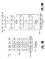
- FIG. 7illustrates wireless power transmission with selective range, where a plurality of pockets of energy may be generated along various radii from transmitter.
- FIG. 8illustrates wireless power transmission with selective range, where a plurality of pockets of energy may be generated along various radii from transmitter.
- FIGS. 9A and 9Billustrate a diagram of an architecture for wirelessly charging client computing platform, according to an exemplary embodiment
- FIG. 10Aillustrates wireless power transmission using multiple pocket-forming, according to an exemplary embodiment.
- FIG. 10Billustrates multiple adaptive pocket-forming, according to an exemplary embodiment.
- FIG. 11illustrates a diagram of a system architecture for wirelessly charging client devices, according to an exemplary embodiment.
- FIG. 12illustrates a method for determining receiver location using antenna element, according to an exemplary embodiment.
- FIG. 13Aillustrates an array subset configuration, according to an exemplary embodiment.
- FIG. 13Billustrates an array subset configuration, according to an exemplary embodiment.
- FIG. 14illustrates a flat transmitter, according to an exemplary embodiment.
- FIG. 15Aillustrates a transmitter, according to an exemplary embodiment.
- FIG. 15Billustrates a box transmitter, according to an exemplary embodiment.
- FIG. 16illustrates a diagram of an architecture for incorporating transmitter into different devices, according to an exemplary embodiment.
- FIG. 17illustrates a transmitter configuration according to an exemplary embodiment.
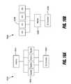
- FIG. 18Aillustrates multiple rectifiers connected in parallel to an antenna element, according to an exemplary embodiment.
- FIG. 18Billustrates multiple antenna elements connected in parallel to a rectifier, according to an exemplary embodiment.
- FIG. 19Aillustrates multiple antenna elements outputs combined and connected to parallel rectifiers, according to an exemplary embodiment.
- FIG. 19Billustrates groups of antenna elements connected to different rectifiers, according to an exemplary embodiment.
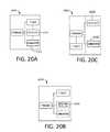
- FIG. 20Aillustrates a device with an embedded receiver, according to an exemplary embodiment.
- FIG. 20Billustrates a battery with an embedded receiver, according to an exemplary embodiment.
- FIG. 20Cillustrates external hardware that may be attached to a device, according to an exemplary embodiment.
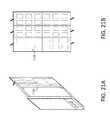
- FIG. 21Aillustrates hardware in the form of case, according to an exemplary embodiment.
- FIG. 21Billustrates hardware in the form of a printed film or flexible printed circuit board, according to an exemplary embodiment.
- FIG. 22illustrates internal hardware according to an exemplary embodiment.
- FIG. 23illustrates an example embodiment of a television (TV) system outputting wireless power.
- FIG. 24illustrates an example embodiment of an internal structure of a TV system.
- FIG. 25illustrates an example embodiment of a tile architecture.
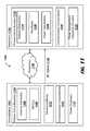
- FIG. 1shows a system 100 for wireless power transmission by forming pockets of energy 104 .
- the system 100may comprise transmitters 101 , receivers 103 , client devices 105 , and pocket detectors 107 .
- Transmitters 101may transmit power transmission signals comprising power transmission waves, which may be captured by receivers 103 .
- the receivers 103may comprise antennas, antenna elements, and other circuitry (detailed later), which may convert the captured waves into a useable source of electrical energy on behalf of client devices 105 associated with the receivers 103 .
- transmitters 101may transmit power transmission signals, made up of power transmission waves, in one or more trajectories by manipulating the phase, gain, and/or other waveform features of the power transmission waves, and/or by selecting different transmit antennas.
- the transmitters 101may manipulate the trajectories of the power transmission signals so that the underlying power transmission waves converge at a location in space, resulting in certain forms of interference.
- constructive interferencemay be a field of energy caused by the convergence of the power transmission waves such that they add together and strengthen the energy concentrated at that location—in contrast to adding together in a way to subtract from each other and diminish the energy concentrated at that location, which is called “destructive interference”.
- the accumulation of sufficient energy at the constructive interferencemay establish a field of energy, or “pocket of energy” 104 , which may be harvested by the antennas of a receiver 103 , provided the antennas are configured to operate on the frequency of the power transmission signals. Accordingly, the power transmission waves establish pockets of energy 104 at the location in space where the receivers 103 may receive, harvest, and convert the power transmission waves into useable electrical energy, which may power or charge associated electrical client devices 105 .
- Detectors 107may be devices comprising a receiver 103 that are capable of producing a notification or alert in response to receiving power transmission signals.
- a user searching for the optimal placement of a receiver 103 to charge the user's client device 105may use a detector 107 that comprises an LED light 108 , which may brighten when the detector 107 captures the power transmission signals from a single beam or a pocket of energy 104 .
- the transmitter 101may transmit or broadcast power transmission signals to a receiver 103 associated with a device 105 .
- the power transmission signalsmay be physical media that is capable of being propagated through space, and that is capable of being converted into a source of electrical energy 103 .
- the transmitter 101may transmit the power transmission signals as a single beam directed at the receivers 103 .
- one or more transmitters 101may transmit a plurality of power transmission signals that are propagated in a multiple directions and may deflect off of physical obstructions (e.g., walls).
- the plurality of power transmission signalsmay converge at a location in a three-dimensional space, forming a pocket of energy 104 .
- Receivers 103 within the boundaries of an energy pocket 104may capture and covert the power transmission signals into a useable source of energy.
- the transmitter 101may control pocket-forming based on phase and/or relative amplitude adjustments of power transmission signals, to form constructive interference patterns.
- wireless charging techniquesshould not be limited to RF wave transmission techniques. Rather, it should be appreciated that possible wireless charging techniques may include any number of alternative or additional techniques for transmitting energy to a receiver converting the transmitted energy to electrical power.
- Non-limiting exemplary transmission techniques for energy that can be converted by a receiving device into electrical powermay include: ultrasound, microwave, resonant and inductive magnetic fields, laser light, infrared, or other forms of electromagnetic energy.
- ultrasoundfor example, one or more transducer elements may be disposed so as to form a transducer array that transmits ultrasound waves toward a receiving device that receives the ultrasound waves and converts them to electrical power.
- the exemplary transmitter 101is shown as a single unit comprising potentially multiple transmitters (transmit array), both for RF transmission of power and for other power transmission methods mentioned in this paragraph, the transmit arrays can comprise multiple transmitters that are physically spread around a room rather than being in a compact regular structure.
- the transmitterincludes an antenna array where the antennas are used for sending the power transmission signal.
- Each antennasends power transmission waves where the transmitter applies a different phase and amplitude to the signal transmitted from different antennas. Similar to the formation of pockets of energy, the transmitter can form a phased array of delayed versions of the signal to be transmitted, then applies different amplitudes to the delayed versions of the signal, and then sends the signals from appropriate antennas. For a sinusoidal waveform, such as an RF signal, ultrasound, microwave, or others, delaying the signal is similar to applying a phase shift to the signal.
- a pocket of energy 104may be formed at locations of constructive interference patterns of power transmission signals transmitted by the transmitter 101 .
- the pockets of energy 104may manifest as a three-dimensional field where energy may be harvested by receivers 103 located within the pocket of energy 104 .
- the pocket of energy 104 produced by transmitters 101 during pocket-formingmay be harvested by a receiver 103 , converted to an electrical charge, and then provided to electronic client device 105 associated with the receiver 103 (e.g., laptop computer, smartphone, rechargeable battery).
- client device 105e.g., laptop computer, smartphone, rechargeable battery.
- adaptive pocket-formingmay adjust transmission of the power transmission signals in order to regulate power levels and/or identify movement of the devices 105 .
- a receiver 103may be used for powering or charging an associated client device 105 , which may be an electrical device coupled to or integrated with the receiver 103 .
- the receiver 103may receive power transmission waves from one or more power transmission signals originating from one or more transmitters 101 .
- the receiver 103may receive the power transmission signals as a single beam produced by the transmitter 101 , or the receiver 103 may harvest power transmission waves from a pocket of energy 104 , which may be a three-dimensional field in space resulting from the convergence of a plurality of power transmission waves produced by one or more transmitters 101 .
- the receiver 103may comprise an array of antennas 112 configured to receive power transmission waves from a power transmission signal and harvest the energy from the power transmission signals of the single beam or pocket of energy 104 .
- the receiver 103may comprise circuitry that then converts the energy of the power transmission signals (e.g., the radio frequency electromagnetic radiation) to electrical energy.
- a rectifier of the receiver 103may translate the electrical energy from AC to DC.
- Other types of conditioningmay be applied, as well.
- a voltage conditioning circuitmay increase or decrease the voltage of the electrical energy as required by the client device 105 .
- An electrical relaymay then convey the electrical energy from the receiver 103 to the client device 105 .
- the receiver 103may comprise a communications component that transmits control signals to the transmitter 101 in order to exchange data in real-time or near real-time.
- the control signalsmay contain status information about the client device 105 , the receiver 103 , or the power transmission signals. Status information may include, for example, present location information of the device 105 , amount of charge received, amount of charged used, and user account information, among other types of information.
- the receiver 103 including the rectifier that it containsmay be integrated into the client device 105 .
- the receiver 103 , wire 111 , and client device 105may be a single unit contained in a single packaging.
- control signalsmay serve as data inputs used by the various antenna elements responsible for controlling production of power transmission signals and/or pocket-forming.
- Control signalsmay be produced by the receiver 103 or the transmitter 101 using an external power supply (not shown) and a local oscillator chip (not shown), which in some cases may include using a piezoelectric material.
- Control signalsmay be RF waves or any other communication medium or protocol capable of communicating data between processors, such as Bluetooth®, RFID, infrared, near-field communication (NFC).
- control signalsmay be used to convey information between the transmitter 101 and the receiver 103 used to adjust the power transmission signals, as well as contain information related to status, efficiency, user data, power consumption, billing, geo-location, and other types of information.
- a detector 107may comprise hardware similar to receivers 103 , which may allow the detector 107 to receive power transmission signals originating from one or more transmitters 101 .
- the detector 107may be used by users to identify the location of pockets of energy 104 , so that users may determine the preferable placement of a receiver 103 .
- the detector 107may comprise an indicator light 108 that indicates when the detector is placed within the pocket of energy 104 . As an example, in FIG.
- detectors 107 a , 107 bare located within the pocket of energy 104 generated by the transmitter 101 , which may trigger the detectors 107 a , 107 b to turn on their respective indicator lights 108 a , 108 b , because the detectors 107 a , 107 b are receiving power transmission signals of the pocket of energy 104 ; whereas, the indicator light 108 c of a third detector 107 c located outside of the pockets of energy 104 , is turned off, because the third detector 107 c is not receiving the power transmission signals from the transmitter 101 . It should be appreciated that the functions of a detector, such as the indicator light, may be integrated into a receiver or into a client device in alternative embodiments as well.
- a client device 105may be any electrical device that requires continuous electrical energy or that requires power from a battery.
- client devices 105may include laptops, mobile phones, smartphones, tablets, music players, toys, batteries, flashlights, lamps, electronic watches, cameras, gaming consoles, appliances, GPS devices, and wearable devices or so-called “wearables” (e.g., fitness bracelets, pedometers, smartwatch), among other types of electrical devices.
- the client device 105 amay be a physical device distinct from the receiver 103 a associated with the client device 105 a .
- the client device 105 amay be connected to the receiver over a wire 111 that conveys converted electrical energy from the receiver 103 a to the client device 105 a .
- other types of datamay be transported over the wire 111 , such as power consumption status, power usage metrics, device identifiers, and other types of data.
- the client device 105 bmay be permanently integrated or detachably coupled to the receiver 103 b , thereby forming a single integrated product or unit.
- the client device 105 bmay be placed into a sleeve that has embedded receivers 103 b and that may detachably couple to the device's 105 b power supply input, which may be typically used to charge the device's 105 b battery.
- the device 105 bmay be decoupled from the receiver, but may remain in the sleeve regardless of whether or not the device 105 b requires an electrical charge or is being used.
- the device 105 bmay comprise an integrated receiver 105 b , which may be permanently integrated into the device 105 b so as to form an indistinct product, device, or unit.
- the device 105 bmay rely almost entirely on the integrated receiver 103 b to produce electrical energy by harvesting pockets of energy 104 .
- the connection between the receiver 103 and the client device 105may be a wire 111 or may be an electrical connection on a circuit board or an integrated circuit, or even a wireless connection, such as inductive or magnetic.
- FIG. 2shows steps of wireless power transmission, according to an exemplary method 200 embodiment.
- a transmitterestablishes a connection or otherwise associates with a receiver (RX). That is, in some embodiments, transmitters and receivers may communicate control data over using a wireless communication protocol capable of transmitting information between two processors of electrical devices (e.g., Bluetooth®, Bluetooth Low Energy (BLE), Wi-Fi, NFC, ZigBee®).
- a wireless communication protocolcapable of transmitting information between two processors of electrical devices (e.g., Bluetooth®, Bluetooth Low Energy (BLE), Wi-Fi, NFC, ZigBee®).
- BLEBluetooth Low Energy
- Wi-FiWireless Fidelity
- NFCwireless Fidelity
- ZigBee®ZigBee®
- the transmittermay scan for receiver's broadcasting advertisement signals or a receiver may transmit an advertisement signal to the transmitter.
- the advertisement signalmay announce the receiver's presence to the transmitter, and may trigger an association between the transmitter and the receiver.
- the advertisement signalmay communicate information that may be used by various devices (e.g., transmitters, client devices, sever computers, other receivers) to execute and manage pocket-forming procedures.
- Information contained within the advertisement signalmay include a device identifier (e.g., MAC address, IP address, UUID), the voltage of electrical energy received, client device power consumption, and other types of data related to power transmission.
- the transmittermay use the advertisement signal transmitted to identify the receiver and, in some cases, locate the receiver in a two-dimensional space or in a three-dimensional space. Once the transmitter identifies the receiver, the transmitter may establish the connection associated in the transmitter with the receiver, allowing the transmitter and receiver to communicate control signals over a second channel.
- the transmittermay use the advertisement signal to determine a set of power transmission signal features for transmitting the power transmission signals, to then establish the pockets of energy.
- features of power transmission signalsmay include phase, gain, amplitude, magnitude, and direction among others.
- the transmittermay use information contained in the receiver's advertisement signal, or in subsequent control signals received from the receiver, to determine how to produce and transmit the power transmission signals so that the receiver may receive the power transmission signals.
- the transmittermay transmit power transmission signals in a way that establishes a pocket of energy, from which the receiver may harvest electrical energy.
- the transmittermay comprise a processor executing software modules capable of automatically identifying the power transmission signal features needed to establish a pocket of energy based on information received from the receiver, such as the voltage of the electrical energy harvested by the receiver from the power transmission signals.
- the functions of the processor and/or the software modulesmay be implemented in an Application Specific Integrated Circuit (ASIC).
- ASICApplication Specific Integrated Circuit
- the advertisement signal or subsequent signal transmitted by the receiver over a second communications channelmay indicate one or more power transmission signals features, which the transmitter may then use to produce and transmit power transmission signals to establish a pocket of energy.
- the transmittermay automatically identify the phase and gain necessary for transmitting the power transmission signals based on the location of the device and the type of device or receiver; and, in some cases, the receiver may inform the transmitter the phase and gain for effectively transmitting the power transmission signals.
- the transmittermay begin transmitting power transmission signals, over a separate channel from the control signals.
- Power transmission signalsmay be transmitted to establish a pocket of energy.
- the transmitter's antenna elementsmay transmit the power transmission signals such that the power transmission signals converge in a two-dimensional or three-dimensional space around the receiver.
- the resulting field around the receiverforms a pocket of energy from which the receiver may harvest electrical energy.
- One antenna elementmay be used to transmit power transmission signals to establish two-dimensional energy transmissions; and in some cases, a second or additional antenna element may be used to transmit power transmission signals in order to establish a three-dimensional pocket of energy.
- a plurality of antenna elementsmay be used to transmit power transmission signals in order to establish the pocket of energy.
- the plurality of antennasmay include all of the antennas in the transmitter; and, in some cases, the plurality of antennas may include a number of the antennas in the transmitter, but fewer than all of the antennas of the transmitter.
- the transmittermay produce and transmit power transmission signals, according to a determined set of power transmission signal features, which may be produced and transmitted using an external power source and a local oscillator chip comprising a piezoelectric material.
- the transmittermay comprise an RFIC that controls production and transmission of the power transmission signals based on information related to power transmission and pocket-forming received from the receiver. This control data may be communicated over a different channel from the power transmission signals, using wireless communications protocols, such as BLE, NFC, or ZigBee®.
- the RFIC of the transmittermay automatically adjust the phase and/or relative magnitudes of the power transmission signals as needed. Pocket-forming is accomplished by the transmitter transmitting the power transmission signals in a manner that forms constructive interference patterns.
- Antenna elements of the transmittermay use concepts of wave interference to determine certain power transmission signals features (e.g., direction of transmission, phase of power transmission signal wave), when transmitting the power transmission signals during pocket-forming.
- the antenna elementsmay also use concepts of constructive interference to generate a pocket of energy, but may also utilize concepts of deconstructive interference to generate a transmission null in a particular physical location.
- the transmittermay provide power to a plurality of receivers using pocket-forming, which may require the transmitter to execute a procedure for multiple pocket-forming.
- a transmitter comprising a plurality of antenna elementsmay accomplish multiple pocket-forming by automatically computing the phase and gain of power transmission signal waves, for each antenna element of the transmitter tasked with transmitting power transmission signals the respective receivers.
- the transmittermay compute the phase and gains independently, because multiple wave paths for each power transmission signal may be generated by the transmitter's antenna elements to transmit the power transmission signals to the respective antenna elements of the receiver.
- Yis 180 degree phase shifted version of X
- the receivermay harvest or otherwise receive electrical energy from power transmission signals of a single beam or a pocket of energy.
- the receivermay comprise a rectifier and AC/DC converter, which may convert the electrical energy from AC current to DC current, and a rectifier of the receiver may then rectify the electrical energy, resulting in useable electrical energy for a client device associated with the receiver, such as a laptop computer, smartphone, battery, toy, or other electrical device.
- the receivermay utilize the pocket of energy produced by the transmitter during pocket-forming to charge or otherwise power the electronic device.
- the receivermay generate control data containing information indicating the effectiveness of the single beam or energy pockets providing the receiver power transmission signals.
- the receivermay then transmit control signals containing the control data, to the transmitter.
- the control signalsmay be transmitted intermittently, depending on whether the transmitter and receiver are communicating synchronously (i.e., the transmitter is expecting to receive control data from the receiver). Additionally, the transmitter may continuously transmit the power transmission signals to the receiver, irrespective of whether the transmitter and receiver are communicating control signals.
- the control datamay contain information related to transmitting power transmission signals and/or establishing effective pockets of energy. Some of the information in the control data may inform the transmitter how to effectively produce and transmit, and in some cases adjust, the features of the power transmission signals.
- Control signalsmay be transmitted and received over a second channel, independent from the power transmission signals, using a wireless protocol capable of transmitting control data related to power transmission signals and/or pocket-forming, such as BLE, NFC, Wi-Fi, or the like.
- control datamay contain information indicating the effectiveness of the power transmission signals of the single beam or establishing the pocket of energy.
- the control datamay be generated by a processor of the receiver monitoring various aspects of receiver and/or the client device associated with the receiver.
- the control datamay be based on various types of information, such as the voltage of electrical energy received from the power transmission signals, the quality of the power transmission signals reception, the quality of the battery charge or quality of the power reception, and location or motion of the receiver, among other types of information useful for adjusting the power transmission signals and/or pocket-forming.
- a receivermay determine the amount of power being received from power transmission signals transmitted from the transmitter and may then indicate that the transmitter should “split” or segment the power transmission signals into less-powerful power transmission signals.
- the less-powerful power transmission signalsmay be bounced off objects or walls nearby the device, thereby reducing the amount of power being transmitted directly from the transmitter to the receiver.
- the transmittermay calibrate the antennas transmitting the power transmission signals, so that the antennas transmit power transmission signals having a more effective set of feature (e.g., direction, phase, gain, amplitude).
- a processor of the transmittermay automatically determine more effective features for producing and transmitting the power transmission signals based on a control signal received from the receiver.
- the control signalmay contain control data, and may be transmitted by the receiver using any number of wireless communication protocols (e.g., BLE, Wi-Fi, ZigBee®).
- the control datamay contain information expressly indicating the more effective features for the power transmission waves; or the transmitter may automatically determine the more effective features based on the waveform features of the control signal (e.g., shape, frequency, amplitude).
- the transmittermay then automatically reconfigure the antennas to transmit recalibrated power transmission signals according to the newly determined more-effective features.
- the processor of the transmittermay adjust gain and/or phase of the power transmission signals, among other features of power transmission feature, to adjust for a change in location of the receiver, after a user moved the receiver outside of the three-dimensional space where the pocket of energy is established.
- FIG. 3illustrates an architecture 300 for wireless power transmission using pocket-forming, according to an exemplary embodiment.
- “Pocket-forming”may refer to generating two or more power transmission waves 342 that converge at a location in three-dimensional space, resulting in constructive interference patterns at that location.
- a transmitter 302may transmit and/or broadcast controlled power transmission waves 342 (e.g., microwaves, radio waves, ultrasound waves) that may converge in three-dimensional space. These power transmission waves 342 may be controlled through phase and/or relative amplitude adjustments to form constructive interference patterns (pocket-forming) in locations where a pocket of energy is intended.
- controlled power transmission waves 342e.g., microwaves, radio waves, ultrasound waves
- the transmittercan use the same principles to create destructive interference in a location thereby creating a transmission null—a location where transmitted power transmission waves cancel each other out substantially and no significant energy can be collected by a receiver.
- the aiming of a power transmission signal at the location of the receiveris the objective; and in other cases it may be desirable to specifically avoid power transmission to a particular location; and in other cases it may be desirable to aim power transmission signal at a location while specifically avoiding transmission to a second location at the same time.
- the transmittertakes the use case into account when calibrating antennas for power transmission.
- Antenna elements 306 of the transmitter 302may operate in single array, pair array, quad array, or any other suitable arrangement that may be designed in accordance with the desired application.
- Pockets of energymay be formed at constructive interference patterns where the power transmission waves 342 accumulate to form a three-dimensional field of energy, around which one or more corresponding transmission null in a particular physical location may be generated by destructive interference patterns.
- Transmission null in a particular physical locationmay refer to areas or regions of space where pockets of energy do not form because of destructive interference patterns of power transmission waves 342 .
- a receiver 320may then utilize power transmission waves 342 emitted by the transmitter 302 to establish a pocket of energy, for charging or powering an electronic device 313 , thus effectively providing wireless power transmission.
- Pockets of energymay refer to areas or regions of space where energy or power may accumulate in the form of constructive interference patterns of power transmission waves 342 .
- adaptive pocket-formingmay be used to regulate power on electronic devices. Adaptive pocket-forming may refer to dynamically adjusting pocket-forming to regulate power on one or more targeted receivers.
- Receiver 320may communicate with transmitter 302 by generating a short signal through antenna elements 324 in order to indicate its position with respect to the transmitter 302 .
- receiver 320may additionally utilize a network interface card (not shown) or similar computer networking component to communicate through a network 340 with other devices or components of the system 300 , such as a cloud computing service that manages several collections of transmitters 302 .
- the receiver 320may comprise circuitry 308 for converting the power transmission signals 342 captured by the antenna elements 324 , into electrical energy that may be provided to and electric device 313 and/or a battery of the device 315 .
- the circuitrymay provide electrical energy to a battery of receiver 335 , which may store energy without the electrical device 313 being communicatively coupled to the receiver 320 .
- Communications components 324may enable receiver 320 to communicate with the transmitter 302 by transmitting control signals 345 over a wireless protocol.
- the wireless protocolcan be a proprietary protocol or use a conventional wireless protocol, such as Bluetooth®, BLE, Wi-Fi, NFC, ZigBee, and the like.
- Communications component 324may then be used to transfer information, such as an identifier for the electronic device 313 , as well as battery level information, geographic location data, or other information that may be of use for transmitter 302 in determining when to send power to receiver 320 , as well as the location to deliver power transmission waves 342 creating pockets of energy.
- adaptive pocket-formingmay be used to regulate power provided to electronic devices 313 .
- the communications components 324 of the receivermay transmit voltage data indicating the amount of power received at the receiver 320 , and/or the amount of voltage provided to an electronic device 313 b or battery 315 .
- transmitter 302identifies and locates receiver 320 , a channel or path for the control signals 345 can be established, through which the transmitter 302 may know the gain and phases of the control signals 345 coming from receiver 320 .
- Antenna elements 306 of the transmitter 302may start to transmit or broadcast controlled power transmission waves 342 (e.g., radio frequency waves, ultrasound waves), which may converge in three-dimensional space by using at least two antenna elements 306 to manipulate the power transmission waves 342 emitted from the respective antenna element 306 .
- These power transmission waves 342may be produced by using an external power source and a local oscillator chip using a suitable piezoelectric material.
- the power transmission waves 342may be controlled by transmitter circuitry 301 , which may include a proprietary chip for adjusting phase and/or relative magnitudes of power transmission waves 342 .
- the phase, gain, amplitude, and other waveform features of the power transmission waves 342may serve as inputs for antenna element 306 to form constructive and destructive interference patterns (pocket-forming).
- a micro-controller 310 or other circuit of the transmitter 302may produce a power transmission signal, which comprises power transmission waves 342 , and that may be may split into multiple outputs by transmitter circuitry 301 , depending on the number of antenna elements 306 connected to the transmitter circuitry 301 .
- the power transmission signalwill be split into four different outputs each output going to an antenna element 306 to be transmitted as power transmission waves 342 originating from the respective antenna elements 306 .
- Pocket-formingmay take advantage of interference to change the directionality of the antenna element 306 where constructive interference generates a pocket of energy and destructive interference generates a transmission null.
- Receiver 320may then utilize pocket of energy produced by pocket-forming for charging or powering an electronic device and therefore effectively providing wireless power transmission.
- Multiple pocket-formingmay be achieved by computing the phase and gain from each antenna 306 of transmitter 302 to each receiver 320 .
- FIG. 4shows components of an exemplary system 400 of wireless power transmission using pocket-forming procedures.
- the system 400may comprise one or more transmitters 402 , one or more receivers 420 , and one or more client devices 446 .
- Transmitters 402may be any device capable of broadcasting wireless power transmission signals, which may be RF waves 442 , for wireless power transmission, as described herein. Transmitters 402 may be responsible for performing tasks related to transmitting power transmission signals, which may include pocket-forming, adaptive pocket-forming, and multiple pocket-forming. In some implementations, transmitters 402 may transmit wireless power transmissions to receivers 420 in the form of RF waves, which may include any radio signal having any frequency or wavelength.
- a transmitter 402may include one or more antenna elements 406 , one or more RFICs 408 , one or more microcontrollers 410 , one or more communication components 412 , a power source 414 , and a housing that may allocate all the requested components for the transmitter 402 .
- the various components of transmitters 402may comprise, and/or may be manufactured using, meta-materials, micro-printing of circuits, nano-materials, and the like.
- the transmitter 402may transmit or otherwise broadcast controlled RF waves 442 that converge at a location in three-dimensional space, thereby forming a pocket of energy 444 .
- These RF wavesmay be controlled through phase and/or relative amplitude adjustments to form constructive or destructive interference patterns (i.e., pocket-forming).
- Pockets of energy 444may be fields formed at constructive interference patterns and may be three-dimensional in shape; whereas transmission null in a particular physical location may be generated at destructive interference patterns.
- Receivers 420may harvest electrical energy from the pockets of energy 444 produced by pocket-forming for charging or powering an electronic client device 446 (e.g., a laptop computer, a cell phone).
- an electronic client device 446e.g., a laptop computer, a cell phone
- the system 400may comprise multiple transmitters 402 and/or multiple receivers 420 , for powering various electronic equipment.
- client devices 446may include: smartphones, tablets, music players, toys and others at the same time.
- adaptive pocket-formingmay be used to regulate power on electronic devices.
- Receivers 420may include a housing where at least one antenna element 424 , one rectifier 426 , one power converter 428 , and a communications component 430 may be included.
- Housing of the receiver 420can be made of any material capable of facilitating signal or wave transmission and/or reception, for example plastic or hard rubber. Housing may be an external hardware that may be added to different electronic equipment, for example in the form of cases, or can be embedded within electronic equipment as well.
- Antenna elements 424 of the receiver 420may comprise any type of antenna capable of transmitting and/or receiving signals in frequency bands used by the transmitter 402 A.
- Antenna elements 424may include vertical or horizontal polarization, right hand or left hand polarization, elliptical polarization, or other polarizations, as well as any number of polarization combinations.
- Using multiple polarizationscan be beneficial in devices where there may not be a preferred orientation during usage or whose orientation may vary continuously through time, for example a smartphone or portable gaming system.
- a preferred polarization for antennaswhich may dictate a ratio for the number of antennas of a given polarization.
- Types of antennas in antenna elements 424 of the receiver 420may include patch antennas, which may have heights from about 1 ⁇ 8 inch to about 6 inches and widths from about 1 ⁇ 8 inch to about 6 inches. Patch antennas may preferably have polarization that depends upon connectivity, i.e., the polarization may vary depending on from which side the patch is fed. In some embodiments, the type of antenna may be any type of antenna, such as patch antennas, capable of dynamically varying the antenna polarization to optimize wireless power transmission.
- Rectifiers 426 of the receiver 420may include diodes, resistors, inductors, and/or capacitors to rectify alternating current (AC) voltage generated by antenna elements 424 to direct current (DC) voltage. Rectifiers 426 may be placed as close as is technically possible to antenna elements A 24 B to minimize losses in electrical energy gathered from power transmission signals. After rectifying AC voltage, the resulting DC voltage may be regulated using power converters 428 . Power converters 428 can be a DC-to-DC converter that may help provide a constant voltage output, regardless of input, to an electronic device, or as in this exemplary system 400 , to a battery. Typical voltage outputs can be from about 5 volts to about 10 volts.
- power convertermay include electronic switched mode DC-DC converters, which can provide high efficiency.
- the receiver 420may comprise a capacitor (not shown) that is situated to receive the electrical energy before power converters 428 .
- the capacitormay ensure sufficient current is provided to an electronic switching device (e.g., switch mode DC-DC converter), so it may operate effectively.
- an electronic switching devicee.g., switch mode DC-DC converter
- a capacitormay be added at the output of receivers 420 to provide the extra energy required.
- lower powercan be provided. For example, 1/80 of the total initial power that may be used while having the phone or laptop still build-up charge.
- a communications component 430 of a receiver 420may communicate with one or more other devices of the system 400 , such as other receivers 420 , client devices, and/or transmitters 402 .
- Different antenna, rectifier or power converter arrangementsare possible for a receiver as will be explained in following embodiments.
- FIG. 5shows steps of powering a plurality of receiver devices, according to an exemplary embodiment.
- a transmitterestablishes a connection or otherwise associates with a receiver (RX). That is, in some embodiments, transmitters and receivers may communicate control data over using a wireless communication protocol capable of transmitting information between two processors of electrical devices (e.g., Bluetooth®, BLE, Wi-Fi, NFC, ZigBee®). For example, in embodiments implement Bluetooth® or Bluetooth® variants, the transmitter may scan for receiver's broadcasting advertisement signals or a receiver may transmit an advertisement signal to the transmitter. The advertisement signal may announce the receiver's presence to the transmitter, and may trigger an association between the transmitter and the receiver.
- a wireless communication protocolcapable of transmitting information between two processors of electrical devices
- the transmittermay scan for receiver's broadcasting advertisement signals or a receiver may transmit an advertisement signal to the transmitter.
- the advertisement signalmay announce the receiver's presence to the transmitter, and may trigger an association between the transmitter and the receiver.
- the advertisement signalmay communicate information that may be used by various devices (e.g., transmitters, client devices, sever computers, other receivers) to execute and manage pocket-forming procedures.
- Information contained within the advertisement signalmay include a device identifier (e.g., MAC address, IP address, UUID), the voltage of electrical energy received, client device power consumption, and other types of data related to power transmission waves.
- the transmittermay use the advertisement signal transmitted to identify the receiver and, in some cases, locate the receiver in a two-dimensional space or in a three-dimensional space. Once the transmitter identifies the receiver, the transmitter may establish the connection associated in the transmitter with the receiver, allowing the transmitter and receiver to communicate control signals over a second channel.
- the Bluetooth processormay begin advertising the receiver according to Bluetooth® standards.
- the transmittermay recognize the advertisement and begin establishing connection for communicating control signals and power transmission signals.
- the advertisement signalmay contain unique identifiers so that the transmitter may distinguish that advertisement and ultimately that receiver from all the other Bluetooth® devices nearby within range.
- the transmittermay automatically form a communication connection with that receiver, which may allow the transmitter and receiver to communicate control signals and power transmission signals.
- the transmittermay then command that receiver to begin transmitting real-time sample data or control data.
- the transmittermay also begin transmitting power transmission signals from antennas of the transmitter's antenna array.
- the receivermay then measure the voltage, among other metrics related to effectiveness of the power transmission signals, based on the electrical energy received by the receiver's antennas.
- the receivermay generate control data containing the measured information, and then transmit control signals containing the control data to the transmitter.
- the receivermay sample the voltage measurements of received electrical energy, for example, at a rate of 100 times per second.
- the receivermay transmit the voltage sample measurement back to the transmitter, 100 times a second, in the form of control signals.
- the transmittermay execute one or more software modules monitoring the metrics, such as voltage measurements, received from the receiver.
- Algorithmsmay vary production and transmission of power transmission signals by the transmitter's antennas, to maximize the effectiveness of the pockets of energy around the receiver.
- the transmittermay adjust the phase at which the transmitter's antenna transmit the power transmission signals, until that power received by the receiver indicates an effectively established pocket energy around the receiver.
- memory of the transmittermay store the configurations to keep the transmitter broadcasting at that highest level.
- algorithms of the transmittermay determine when it is necessary to adjust the power transmission signals and may also vary the configuration of the transmit antennas, in response to determining such adjustments are necessary. For example, the transmitter may determine the power received at a receiver is less than maximal, based on the data received from the receiver. The transmitter may then automatically adjust the phase of the power transmission signals, but may also simultaneously continues to receive and monitor the voltage being reported back from receiver.
- the transmittermay scan and/or automatically detect advertisements from other receivers that may be in range of the transmitter.
- the transmittersmay establish a connection to the second receiver responsive to Bluetooth® advertisements from a second receiver.
- the transmittermay proceed to adjust one or more antennas in the transmitter's antenna array.
- the transmittermay identify a subset of antennas to service the second receiver, thereby parsing the array into subsets of arrays that are associated with a receiver.
- the entire antenna arraymay service a first receiver for a given period of time, and then the entire array may service the second receiver for that period of time.
- Manual or automated processes performed by the transmittermay select a subset of arrays to service the second receiver.
- the transmitter's arraymay be split in half, forming two subsets.
- half of the antennasmay be configured to transmit power transmission signals to the first receiver, and half of the antennas may be configured for the second receiver.
- the transmittermay apply similar techniques discussed above to configure or optimize the subset of antennas for the second receiver. While selecting a subset of an array for transmitting power transmission signals, the transmitter and second receiver may be communicating control data.
- the transmitterhas already received a sufficient amount of sample data to adjust the phases of the waves transmitted by second subset of the transmitter's antenna array, to transmit power transmission waves to the second receiver effectively.
- the transmittermay alternate back to communicating control data with the first receiver, or scanning for additional receivers.
- the transmittermay reconfigure the antennas of the first subset, and then alternate between the first and second receivers at a predetermined interval.
- the transmittermay continue to alternate between receivers and scanning for new receivers, at a predetermined interval. As each new receiver is detected, the transmitter may establish a connection and begin transmitting power transmission signals, accordingly.
- the receivermay be electrically connected to a device like a smart phone.
- the transmitter's processorwould scan for any Bluetooth devices.
- the receivermay begin advertising that it's a Bluetooth device through the Bluetooth chip. Inside the advertisement, there may be unique identifiers so that the transmitter, when it scanned that advertisement, could distinguish that advertisement and ultimately that receiver from all the other Bluetooth devices nearby within range.
- the transmitterdetects that advertisement and notices it is a receiver, then the transmitter may immediately form a communication connection with that receiver and command that receiver to begin sending real time sample data.
- the receiverwould then measure the voltage at its receiving antennas, send that voltage sample measurement back to the transmitter (e.g., 100 times a second).
- the transmittermay start to vary the configuration of the transmit antennas by adjusting the phase. As the transmitter adjusts the phase, the transmitter monitors the voltage being sent back from the receiver. In some implementations, the higher the voltage, the more energy may be in the pocket.
- the antenna phasesmay be altered until the voltage is at the highest level and there is a maximum pocket of energy around the receiver. The transmitter may keep the antennas at the particular phase so the voltage is at the highest level.
- the transmittermay vary each individual antenna, one at a time. For example, if there are 32 antennas in the transmitter, and each antenna has 8 phases, the transmitter may begin with the first antenna and would step the first antenna through all 8 phases. The receiver may then send back the power level for each of the 8 phases of the first antenna. The transmitter may then store the highest phase for the first antenna. The transmitter may repeat this process for the second antenna, and step it through 8 phases. The receiver may again send back the power levels from each phase, and the transmitter may store the highest level. Next the transmitter may repeat the process for the third antenna and continue to repeat the process until all 32 antennas have stepped through the 8 phases. At the end of the process, the transmitter may transmit the maximum voltage in the most efficient manner to the receiver.
- the transmittermay detect a second receiver's advertisement and form a communication connection with the second receiver.
- the transmittermay aim the original 32 antennas towards the second receiver and repeat the phase process for each of the 32 antennas aimed at the second receiver.
- the second receivermay getting as much power as possible from the transmitter.
- the transmittermay communicate with the second receiver for a second, and then alternate back to the first receiver for a predetermined period of time (e.g., a second), and the transmitter may continue to alternate back and forth between the first receiver and the second receiver at the predetermined time intervals.
- the transmittermay detect a second receiver's advertisement and form a communication connection with the second receiver.
- the transmittermay communicate with the first receiver and re-assign half of the exemplary 32 the antennas aimed at the first receiver, dedicating only 16 towards the first receiver.
- the transmittermay then assign the second half of the antennas to the second receiver, dedicating 16 antennas to the second receiver.
- the transmittermay adjust the phases for the second half of the antennas. Once the 16 antennas have gone through each of the 8 phases, the second receiver may be obtaining the maximum voltage in the most efficient manner to the receiver.
- FIG. 6A and FIG. 6Bshow an exemplary system 600 implementing wireless power transmission principles that may be implemented during exemplary pocket-forming processes.
- a transmitter 601comprising a plurality of antennas in an antenna array, may adjust the phase and amplitude, among other possible attributes, of power transmission waves 607 , being transmitted from antennas of the transmitter 601 .
- power transmission waves 607 amay be transmitted from each of the antennas will arrive at different locations and have different phases. These differences are often due to the different distances from each antenna element of the transmitter 601 a to a receiver 605 a or receivers 605 a , located at the respective locations.
- a receiver 605 amay receive multiple power transmission signals, each comprising power transmission waves 607 a , from multiple antenna elements of a transmitter 601 a ; the composite of these power transmission signals may be essentially zero, because in this example, the power transmission waves add together destructively. That is, antenna elements of the transmitter 601 a may transmit the exact same power transmission signal (i.e., comprising power transmission waves 607 a having the same features, such as phase and amplitude), and as such, when the power transmission waves 607 a of the respective power transmission signals arrive at the receiver 605 a , they are offset from each other by 180 degrees. Consequently, the power transmission waves 607 a of these power transmission signals “cancel” one another. Generally, signals offsetting one another in this way may be referred to as “destructive,” and thus result in “destructive interference.”
- signalscomprising power transmission waves 607 b that arrive at the receiver exactly “in phase” with one another, combine to increase the amplitude of the each signal, resulting in a composite that is stronger than each of the constituent signals.
- the phase of the power transmission waves 607 a in the transmit signalsare the same at the location of transmission, and then eventually add up destructively at the location of the receiver 605 a .
- the phase of the power transmission waves 607 b of the transmit signalsare adjusted at the location of transmission, such that they arrive at the receiver 605 b in phase alignment, and consequently they add constructively.
- there will be a resulting pocket of energy located around the receiver 605 b in FIG. 6Band there will be a transmission null located around receiver in FIG. 6A .
- FIG. 7depicts wireless power transmission with selective range 700 , where a transmitter 702 may produce pocket-forming for a plurality of receivers associated with electrical devices 701 .
- Transmitter 702may generate pocket-forming through wireless power transmission with selective range 700 , which may include one or more wireless charging radii 704 and one or more radii of a transmission null at a particular physical location 706 .
- a plurality of electronic devices 701may be charged or powered in wireless charging radii 704 .
- spots of energymay be created, such spots may be employed for enabling restrictions for powering and charging electronic devices 701 .
- the restrictionsmay include operating specific electronics in a specific or limited spot, contained within wireless charging radii 704 .
- safety restrictionsmay be implemented by the use of wireless power transmission with selective range 700 , such safety restrictions may avoid pockets of energy over areas or zones where energy needs to be avoided, such areas may include areas including sensitive equipment to pockets of energy and/or people which do not want pockets of energy over and/or near them.
- the transmitter 702may comprise antenna elements found on a different plane than the receivers associated with electrical devices 701 in the served area.
- the receivers of electrical devices 701may be in a room where a transmitter 702 may be mounted on the ceiling.
- Selective ranges for establishing pockets of energy using power transmission waveswhich may be represented as concentric circles by placing an antenna array of the transmitter 702 on the ceiling or other elevated location, and the transmitter 702 may emit power transmission waves that will generate ‘cones’ of energy pockets.
- the transmitter 701may control the radius of each charging radii 704 , thereby establishing intervals for service area to create pockets of energy that are pointed down to an area at a lower plane, which may adjust the width of the cone through appropriate selection of antenna phase and amplitudes.
- FIG. 8depicts wireless power transmission with selective range 800 , where a transmitter 802 may produce pocket-forming for a plurality of receivers 806 .
- Transmitter 802may generate pocket-forming through wireless power transmission with selective range 800 , which may include one or more wireless charging spots 804 .
- a plurality of electronic devicesmay be charged or powered in wireless charging spots 804 .
- Pockets of energymay be generated over a plurality of receivers 806 regardless the obstacles 804 surrounding them. Pockets of energy may be generated by creating constructive interference, according to the principles described herein, in wireless charging spots 804 .
- Location of pockets of energymay be performed by tacking receivers 806 and by enabling a plurality of communication protocols by a variety of communication systems such as, Bluetooth® technology, infrared communication, Wi-Fi, FM radio, among others.
- FIGS. 9A and 9Billustrate a diagram of architecture 900 A, 900 B for a wirelessly charging client computing platform, according to an exemplary embodiment.
- a usermay be inside a room and may hold on his hands an electronic device (e.g. a smartphone, tablet).
- electronic devicemay be on furniture inside the room.
- the electronic devicemay include a receiver 920 A, 920 B either embedded to the electronic device or as a separate adapter connected to electronic device.
- Receivers 920 A, 920 Bmay include all the components described in FIG. 11 .
- a transmitter 902 A, 902 Bmay be hanging on one of the walls of the room right behind user.
- Transmitters 902 A, 902 Bmay also include all the components described in FIG. 11 .
- RF wavesmay not be easily aimed to the receivers 920 A, 920 B in a linear direction.
- the short signals generated from receivers 920 A, 920 Bmay be omni-directional for the type of antenna element used, these signals may bounce over the walls 944 A, 944 B until they reach transmitters 902 A, 902 B.
- a hot spot 944 A, 944 Bmay be any item in the room which will reflect the RF waves.
- a large metal clock on the wallmay be used to reflect the RF waves to a user's cell phone.
- a micro controller in the transmitteradjusts the transmitted signal from each antenna based on the signal received from the receiver. Adjustment may include forming conjugates of the signal phases received from the receivers and further adjustment of transmit antenna phases taking into account the built-in phase of antenna elements.
- the antenna elementmay be controlled simultaneously to steer energy in a given direction.
- the transmitter 902 A, 902 Bmay scan the room, and look for hot spots 944 A, 944 B. Once calibration is performed, transmitters 902 A, 902 B may focus RF waves in a channel following a path that may be the most efficient paths. Subsequently, RF signals 942 A, 942 B may form a pocket of energy on a first electronic device and another pocket of energy in a second electronic device while avoiding obstacles such as user and furniture.
- the transmitter 902 A, 902 Bmay employ different methods.
- the transmitter 902 A, 902 Bmay detect the phases and magnitudes of the signal coming from the receiver and use those to form the set of transmit phases and magnitudes, for example by calculating conjugates of them and applying them at transmit.
- the transmittermay apply all possible phases of transmit antennas in subsequent transmissions, one at a time, and detect the strength of the pocket of energy formed by each combination by observing information related to the signal from the receiver 920 A, 920 B. Then the transmitter 902 A, 902 B repeats this calibration periodically.
- the transmitter 902 A, 902 Bdoes not have to search through all possible phases, and can search through a set of phases that are more likely to result in strong pockets of energy based on prior calibration values.
- the transmitter 902 A, 902 Bmay use preset values of transmit phases for the antennas to form pockets of energy directed to different locations in the room.
- the transmittermay for example scan the physical space in the room from top to bottom and left to right by using preset phase values for antennas in subsequent transmissions.
- the transmitter 902 A, 902 Bdetects the phase values that result in the strongest pocket of energy around the receiver 920 a , 920 b by observing the signal from the receiver 920 a , 920 b .
- the result of a scanis a heat-map of the service area (e.g., room, store) from which the transmitter 902 A, 902 B may identify the hot spots that indicate the best phase and magnitude values to use for transmit antennas in order to maximize the pocket of energy around the receiver.
- the service areae.g., room, store
- the transmitters 902 A, 902 Bmay use the Bluetooth connection to determine the location of the receivers 920 A, 920 B, and may use different non-overlapping parts of the RF band to channel the RF waves to different receivers 920 A, 920 B.
- the transmitters 902 A, 902 Bmay conduct a scan of the room to determine the location of the receivers 920 A, 920 B and forms pockets of energy that are orthogonal to each other, by virtue of non-overlapping RF transmission bands. Using multiple pockets of energy to direct energy to receivers may inherently be safer than some alternative power transmission methods since no single transmission is very strong, while the aggregate power transmission signal received at the receiver is strong.
- FIG. 10Aillustrates wireless power transmission using multiple pocket-forming 1000 A that may include one transmitter 1002 A and at least two or more receivers 1020 A.
- Receivers 1020 Amay communicate with transmitters 1002 A, which is further described in FIG. 11 .
- transmitter 1002 Aidentifies and locates receivers 1020 A, a channel or path can be established by knowing the gain and phases coming from receivers 1020 A.
- Transmitter 1002 Amay start to transmit controlled RF waves 1042 A which may converge in three-dimensional space by using a minimum of two antenna elements. These RF waves 1042 A may be produced using an external power source and a local oscillator chip using a suitable piezoelectric material.
- RF waves 1042 Amay be controlled by RFIC, which may include a proprietary chip for adjusting phase and/or relative magnitudes of RF signals that may serve as inputs for antenna elements to form constructive and destructive interference patterns (pocket-forming). Pocket-forming may take advantage of interference to change the directionality of the antenna elements where constructive interference generates a pocket of energy 1060 A and deconstructive interference generates a transmission null. Receivers 1020 A may then utilize pocket of energy 1060 A produced by pocket-forming for charging or powering an electronic device, for example, a laptop computer 1062 A and a smartphone 1052 A and thus effectively providing wireless power transmission.
- RFICmay include a proprietary chip for adjusting phase and/or relative magnitudes of RF signals that may serve as inputs for antenna elements to form constructive and destructive interference patterns (pocket-forming). Pocket-forming may take advantage of interference to change the directionality of the antenna elements where constructive interference generates a pocket of energy 1060 A and deconstructive interference generates a transmission null.
- Receivers 1020 Amay then
- Multiple pocket forming 1000 Amay be achieved by computing the phase and gain from each antenna of transmitter 1002 A to each receiver 1020 A. The computation may be calculated independently because multiple paths may be generated by antenna element from transmitter 1002 A to antenna element from receivers 1020 A.
- FIG. 10Bis an exemplary illustration of multiple adaptive pocket-forming 1000 B.
- a usermay be inside a room and may hold on his hands an electronic device, which in this case may be a tablet 1064 B.
- smartphone 1052 Bmay be on furniture inside the room.
- Tablet 1064 B and smartphone 1052 Bmay each include a receiver either embedded to each electronic device or as a separate adapter connected to tablet 1064 B and smartphone 1052 B.
- Receivermay include all the components described in FIG. 11 .
- a transmitter 1002 Bmay be hanging on one of the walls of the room right behind user.
- Transmitter 1002 Bmay also include all the components described in FIG. 11 .
- RF waves 1042 Bmay not be easily aimed to each receiver in a line of sight fashion.
- the short signals generated from receiversmay be omni-directional for the type of antenna elements used, these signals may bounce over the walls until they find transmitter 1002 B.
- a micro-controllerwhich may reside in transmitter 1002 B, may recalibrate the transmitted signals, based on the received signals sent by each receiver, by adjusting gain and phases and forming a convergence of the power transmission waves such that they add together and strengthen the energy concentrated at that location—in contrast to adding together in a way to subtract from each other and diminish the energy concentrated at that location, which is called “destructive interference” and conjugates of the signal phases received from the receivers and further adjustment of transmit antenna phases taking into account the built-in phase of antenna elements.
- transmitter 1002 Bmay focus RF waves following the most efficient paths.
- a pocket of energy 1060 Bmay form on tablet 1064 B and another pocket of energy 1060 B in smartphone 1052 B while taking into account obstacles such as user and furniture.
- the foregoing propertymay be beneficial in that wireless power transmission using multiple pocket-forming 1000 B may inherently be safe as transmission along each pocket of energy is not very strong, and that RF transmissions generally reflect from living tissue and do not penetrate.
- Transmitter 1002 Bmay start to transmit controlled RF waves 1042 B that may converge in three-dimensional space by using a minimum of two antenna elements. These RF waves 1042 B may be produced using an external power source and a local oscillator chip using a suitable piezoelectric material. RF waves 1042 B may be controlled by RFIC that may include a proprietary chip for adjusting phase and/or relative magnitudes of RF signals, which may serve as inputs for antenna elements to form constructive and destructive interference patterns (pocket-forming).
- Pocket-formingmay take advantage of interference to change the directionality of the antenna elements where constructive interference generates a pocket of energy and deconstructive interference generates a null in a particular physical location. Receiver may then utilize pocket of energy produced by pocket-forming for charging or powering an electronic device, for example a laptop computer and a smartphone and thus effectively providing wireless power transmission.
- Multiple pocket-forming 1000 Bmay be achieved by computing the phase and gain from each antenna of transmitter to each receiver. The computation may be calculated independently because multiple paths may be generated by antenna elements from transmitter to antenna elements from receiver.
- An example of the computation for at least two antenna elementsmay include determining the phase of the signal from the receiver and applying the conjugate of the receive parameters to the antenna elements for transmission.
- two or more receiversmay operate at different frequencies to avoid power losses during wireless power transmission. This may be achieved by including an array of multiple embedded antenna elements in transmitter 1002 B.
- a single frequencymay be transmitted by each antenna in the array.
- some of the antennas in the arraymay be used to transmit at a different frequency. For example, 1 ⁇ 2 of the antennas in the array may operate at 2.4 GHz while the other 1 ⁇ 2 may operate at 5.8 GHz.
- 1 ⁇ 3 of the antennas in the arraymay operate at 900 MHz, another 1 ⁇ 3 may operate at 2.4 GHz, and the remaining antennas in the array may operate at 5.8 GHz.
- each array of antenna elementsmay be virtually divided into one or more antenna elements during wireless power transmission, where each set of antenna elements in the array can transmit at a different frequency.
- an antenna element of the transmittermay transmit power transmission signals at 2.4 GHz, but a corresponding antenna element of a receiver may be configured to receive power transmission signals at 5.8 GHz.
- a processor of the transmittermay adjust the antenna element of the transmitter to virtually or logically divide the antenna elements in the array into a plurality patches that may be fed independently. As a result, 1 ⁇ 4 of the array of antenna elements may be able to transmit the 5.8 GHz needed for the receiver, while another set of antenna elements may transmit at 2.4 GHz.
- each antenna elementmay alternate between select frequencies.
- the efficiency of wireless power transmission as well as the amount of power that can be delivered (using pocket-forming)may be a function of the total number of antenna elements 1006 used in a given receivers and transmitters system. For example, for delivering about one watt at about 15 feet, a receiver may include about 80 antenna elements while a transmitter may include about 256 antenna elements. Another identical wireless power transmission system (about 1 watt at about 15 feet) may include a receiver with about 40 antenna elements, and a transmitter with about 512 antenna elements. Reducing in half the number of antenna elements in a receiver may require doubling the number of antenna elements in a transmitter.
- the oppositecan be achieved, e.g., by placing more antenna elements on a receiver than on a transmitter as long as there are at least two antenna elements in a transmitter 1002 B.
- Transmittersmay be responsible for the pocket-forming, adaptive pocket-forming and multiple pocket-forming using the components described below.
- Transmittersmay transmit wireless power transmission signals to receivers in the form of any physical media capable of propagating through space and being converted into useable electrical energy; examples may include RF waves, infrared, acoustics, electromagnetic fields, and ultrasound. It should be appreciated by those skilled in the art that power transmission signals may be most any radio signal, having any frequency or wavelength.
- Transmittersare described within with reference to RF transmissions, only as an example, and not to limit the scope to RF transmission only.
- Transmittersmay be located in number of locations, surfaces, mountings, or embedded structures, such as, desks, tables, floors, walls, and the like.
- transmittersmay be located in a client computing platforms, which may be any computing device comprising processors and software modules capable of executing the processes and tasks described herein.
- client computing platformsmay include a desktop computer, a laptop computer, a handheld computer, a tablet computing platform, a netbook, a smartphone, a gaming console, and/or other computing platforms.
- the client computing platformsmay be a variety of electronic computing devices. In such embodiments, each of the client computing platforms may have distinct operating systems, and/or physical components.
- the client computing platformsmay be executing the same operating system and/or the client computing platforms may be executing different operating systems.
- the client computing platforms and or devicesmay be capable of executing multiple operating systems.
- box transmittersmay contain several arrangements of printed circuit board (PCB) layers, which may be oriented in X, Y, or Z axis, or in any combination of these.
- PCBprinted circuit board
- wireless charging techniquesare not limited to RF wave transmission techniques, but may include alternative or additional techniques for transmitting energy to a receiver converting the transmitted energy to electrical power.
- Non-limiting exemplary transmission techniques for energy that can be converted by a receiving device into electrical powermay include: ultrasound, microwave, resonant and inductive magnetic fields, laser light, infrared, or other forms of electromagnetic energy.
- ultrasoundfor example, one or more transducer elements may be disposed so as to form a transducer array that transmits ultrasound waves toward a receiving device that receives the ultrasound waves and converts them to electrical power.
- resonant or inductive magnetic fieldsmagnetic fields are created in a transmitter coil and converted by a receiver coil into electrical power.
- FIG. 11illustrates a diagram of a system 1100 architecture for wirelessly charging client devices, according to an exemplary embodiment.
- the system 1100may comprise a transmitter 1101 and a receiver 1120 that may each comprise an application-specific integrated circuit (ASIC).
- the transmitter 1101 ASICmay include one or more printed circuit boards (PCB) 1104 , one or more antenna elements 1106 , one or more radio frequency integrated circuits (RFIC) 1108 , one or more microcontrollers (MCs) 1110 , a communication component 1112 , a power source 1114 .
- the transmitter 1101may be encased in a housing, which may allocate all the requested components for transmitter 1101 .
- Components in transmitter 1101may be manufactured using meta-materials, micro-printing of circuits, nano-materials, and/or any other materials. It should be obvious to someone skilled in the art that the entire transmitter or the entire receiver can be implemented on a single circuit board, as well as having one or more of the functional blocks implemented in separate circuit boards.
- the transmitter 1101may include a plurality of PCB 1104 layers, which may include antenna element 1106 and/or RFIC 1108 for providing greater control over pocket-forming and may increase response for targeting receivers.
- the PCB 1104may mechanically support and electrically connect the electronic component described herein using conductive tracks, pads and/or other features etched from copper sheets laminated onto a non-conductive substrate.
- PCBsmay be single sided (one copper layer), double sided (two copper layers), and/or multi-layer. Multiple PCB 1104 layers may increase the range and the amount of power that could be transferred by transmitter 1101 .
- PCB 1104 layersmay be connected to a single MC 1110 and/or to dedicated MCs 1110 .
- RFIC 1108may be connected to antenna element 1106 as depicted in the foregoing embodiments.
- a box transmitterincluding a plurality of PCB 1104 layers inside it may include antenna element 1108 for providing greater control over pocket-forming and may increase the response for targeting receivers.
- range of wireless power transmissionmay be increased by the box transmitter.
- Multiple PCB 1104 layersmay increase the range and the amount of power waves (e.g., RF power waves, ultrasound waves) that could be transferred and/or broadcasted wirelessly by transmitter 1101 due the higher density of antenna element 1106 .
- the PCB 1104 layersmay be connected to a single microcontroller 1110 and/or to dedicated microcontroller 1110 for each antenna element 1106 .
- RFIC 1108may control antenna element 1101 as depicted in the foregoing embodiments.
- box shape of transmitter 1101may increase action ratio of wireless power transmission.
- Antenna element 1106may be directional and/or omni-directional and include flat antenna elements, patch antenna elements, dipole antenna elements, and any other suitable antenna for wireless power transmission. Suitable antenna types may include, for example, patch antennas with heights from about 1 ⁇ 8 inch to about 6 inches and widths from about 1 ⁇ 8 inch to about 6 inches.
- the shape and orientation of antenna element 1106may vary in dependency of the desired features of transmitter 1101 ; orientation may be flat in X, Y, and Z axis, as well as various orientation types and combinations in three dimensional arrangements.
- Antenna element 1106 materialsmay include any suitable material that may allow RF signal transmission with high efficiency, good heat dissipation and the like.
- the amount of antenna elements 1106may vary in relation with the desired range and power transmission capability on transmitter 1101 ; the more antenna elements 1106 , the wider range and higher power transmission capability.
- Antenna element 1106may include suitable antenna types for operating in frequency bands such as 900 MHz, 2.5 GHz or 5.8 GHz as these frequency bands conform to Federal Communications Commission (FCC) regulations part 18 (industrial, scientific, and medical equipment). Antenna element 1106 may operate in independent frequencies, allowing a multichannel operation of pocket-forming.
- FCCFederal Communications Commission
- antenna element 1106may have at least one polarization or a selection of polarizations. Such polarization may include vertical polarization, horizontal polarization, circularly polarized, left hand polarized, right hand polarized, or a combination of polarizations. The selection of polarizations may vary in dependency of transmitter 1101 characteristics. In addition, antenna element 1106 may be located in various surfaces of transmitter 1101 . Antenna element 1106 may operate in single array, pair array, quad array and any other suitable arrangement that may be designed in accordance with the desired application.
- the entire side of the printed circuit board PCB 1104may be closely packed with antenna element 1106 .
- the RFIC 1108may connect to multiple antenna elements 1106 .
- Multiple antenna elements 1106may surround a single RFIC 1108 .
- the RFIC 1108may receive an RF signal from the MC 1110 , and split the RF signal into multiple outputs, each output linked to an antenna element 1106 .
- each RFIC 1108may be connected to four antenna elements 1106 .
- each RFIC 1108may be connected to eight, sixteen, and/or multiple antenna elements 1106 .
- the RFIC 1104may include a plurality of RF circuits that may include digital and/or analog components, such as, amplifiers, capacitors, oscillators, piezoelectric crystals and the like.
- RFIC 1104may control features of antenna element 1106 , such as gain and/or phase for pocket-forming and manage it through direction, power level, and the like.
- the phase and the amplitude of pocket-forming in each antenna element 1106may be regulated by the corresponding RFIC 1108 in order to generate the desired pocket-forming and transmission null steering.
- RFIC 1108may be connected to MC 1110 , which may utilize digital signal processing (DSP), ARM, PIC-Class microprocessor, central processing unit, computer, and the like.
- DSPdigital signal processing
- ARMPIC-Class microprocessor
- central processing unitcomputer, and the like.
- the lower number of RFICs 1108 present in the transmitter 1101may correspond to desired features such as lower control of multiple pocket-forming, lower levels of granularity, and a less expensive embodiment.
- RFIC 1108may be coupled to one or more MCs 1110 , and MC 1110 may be included into an independent base station or into the transmitter 1101 .
- each pocket-forming in each antenna element 1106may be regulated by the corresponding RFIC 1108 in order to generate the desired pocket-forming and transmission null steering.
- RFIC 1108 singled coupled to each antenna element 1106may reduce processing requirement and may increase control over pocket-forming, allowing multiple pocket-forming and a higher granular pocket-forming with less load over MC 1110 , and a higher response of higher number of multiple pocket-forming may be allowed.
- multiple pocket-formingmay charge a higher number of receivers and may allow a better trajectory to such receivers.
- RFIC 1108 and antenna element 1106may operate in any suitable arrangement that may be designed in accordance with the desired application.
- transmitter 1101may include antenna element 1106 and RFIC 1108 in a flat arrangement.
- a subset of 4, 8, 16, and/or any number of antenna elements 1106may be connected to a single RFIC 1108 .
- RFIC 1108may be directly embedded behind each antenna element 1106 ; such integration may reduce losses due the shorter distance between components.
- a row or column of antenna elements 1106may be connected to a single MC 1110 .
- RFIC 1108 connected to each row or columnmay allow a less expensive transmitter 1101 that may produce pocket-forming by changing phase and gain between rows or columns.
- the RFIC 1108may output between 2-8 volts of power for the receiver 1120 to obtain.
- a cascade arrangement of RFICs 1108may be implemented.
- a flat transmitter 1101 using a cascade arrangement of RFICs 1108may provide greater control over pocket-forming and may increase response for targeting receivers 1106 , as well as a higher reliability and accuracy may be achieved because multiple redundancy of RFICs 1108 .
- the MC 1110may comprise a processor running ARM and/or DSP.
- ARMis a family of general purpose microprocessors based on a reduced instruction set computing (RISC).
- RISCreduced instruction set computing
- a DSPis a general purpose signal processing chip may provide a mathematical manipulation of an information signal to modify or improve it in some way, and can be characterized by the representation of discrete time, discrete frequency, and/or other discrete domain signals by a sequence of numbers or symbols and the processing of these signals.
- DSPmay measure, filter, and/or compress continuous real-world analog signals.
- the first stepmay be conversion of the signal from an analog to a digital form, by sampling and then digitizing it using an analog-to-digital converter (ADC), which may convert the analog signal into a stream of discrete digital values.
- ADCanalog-to-digital converter
- the MC 1110may also run Linux and/or any other operating system.
- the MC 1110may also be connected to Wi-Fi in order to provide information
- MC 1110may control a variety of features of RFIC 1108 such as, time emission of pocket-forming, direction of the pocket-forming, bounce angle, power intensity and the like. Furthermore, MC 1110 may control multiple pocket-forming over multiple receivers or over a single receiver. Transmitter 1101 may allow distance discrimination of wireless power transmission. In addition, MC 1110 may manage and control communication protocols and signals by controlling communication component 1112 . MC 1110 may process information received by communication component 1112 that may send and receive signals to and from a receiver in order to track it and concentrate radio frequency signals 1142 (i.e., pockets of energy) on it. Other information may be transmitted from and to receiver 1120 ; such information may include authentication protocols among others through a network 1140 .
- radio frequency signals 1142i.e., pockets of energy
- the MC 1110may communicate with the communication component 1112 through serial peripheral interface (SPI) and/or inter-integrated circuit (I 2 C) protocol.
- SPI communicationmay be used for short distance, single master communication, for example in embedded systems, sensors, and SD cards.
- Devicescommunicate in master/slave mode where the master device initiates the data frame. Multiple slave devices are allowed with individual slave select lines.
- I 2 Cis a multi-master, multi-slave, single-ended, serial computer bus used for attaching low-speed peripherals to computer motherboards and embedded systems
- Communication component 1112may include and combine Bluetooth technology, infrared communication, Wi-Fi, FM radio among others. MC 1110 may determine optimum times and locations for pocket-forming, including the most efficient trajectory to transmit pocket forming in order to reduce losses because obstacles. Such trajectory may include direct pocket-forming, bouncing, and distance discrimination of pocket-forming. In some implementations, the communication component 1112 may communicate with a plurality of devices, which may include receivers 1120 , client devices, or other transmitters 1101 .
- Transmitters 1101may be fed by a power source 1114 that may include AC or DC power supply. Voltage, power, and current intensity provided by power source 1114 may vary in dependency with the required power to be transmitted. Conversion of power to radio signal may be managed by MC 1110 and carried out by RFIC 1108 that may utilize a plurality of methods and components to produce radio signals in a wide variety of frequencies, wavelength, intensities, and other features. As an exemplary use of a variety of methods and components for radio signal generation, oscillators and piezoelectric crystals may be used to create and change radio frequencies in different antenna elements 1106 . In addition, a variety of filters may be used for smoothing signals as well as amplifiers for increasing power to be transmitted.
- Transmitter 1101may emit RF power waves that are pocket-forming with a power capability from few watts to a predetermined number of watts required by a particular chargeable electronic device. Each antenna may manage a certain power capacity. Such power capacity may be related with the application
- an independent base stationmay include MC 1110 and power source 1114 , thus, several transmitters 1101 may be managed by a single base station and a single MC 1110 . Such capability may allow the location of transmitters 1101 in a variety of strategic positions, such as ceiling, decorations, walls, and the like.
- Antenna elements 1106 , RFIC 1108 , MC 1110 , communication component 1112 , and power source 1114may be connected in a plurality of arrangements and combinations, which may depend on the desired characteristics of transmitter 1101 .
- FIG. 12is a method for determining receiver location 1200 using antenna element.
- Method for determining receiver location 1200may be a set of programmed rules or logic managed by MC.
- the processmay begin step 1201 by capturing first signal with a first subset of antennas from the antenna array.
- the processmay follow immediately by switching to a different subset of antenna element and capturing, at a next step 1203 , a second signal with a second subset of antennas.
- a first signalmay be captured with a row of antennas and the second capturing may be done with a column of antennas.
- a row of antennasmay provide a horizontal degree orientation such an azimuth in a spherical coordinate system.
- a column of antennasmay provide a vertical degree orientation such as elevation.
- Antenna elements used for capturing first signal and capturing second signalmay be aligned in straight, vertical, horizontal, or diagonal orientation.
- the first subset and second subset of antennasmay be aligned in a cross like
- the MCmay, in a next step 1205 , determine the appropriate values of phase and gain for the vertical and horizontal antenna elements used to capture the signal. Appropriate values for phase and gain may be determined by the relationship of the position of the receiver to the antenna. The values may be used by MC in order to adjust antenna elements to form pockets of energy that may be used by a receiver in order to charge an electronic device.
- Data pertaining to initial values of all antenna elements in transmittermay be calculated and stored previously for use by MC in order to assist in the calculation of appropriate values for antenna elements.
- the processmay continue by using the stored data to determine appropriate values for all the antennas in the array.
- Stored datamay contain initial test values of phase and gain for all antenna elements in the array at different frequencies. Different sets of data may be stored for different frequencies and MC may select the appropriate data set accordingly.
- MCmay then adjust all antennas through RFIC in order to form pockets of energy at the appropriate locations.
- FIG. 13Aillustrates an example embodiment of an array subset configuration 1300 A that may be used in method for determining receiver location.
- Transmittermay include an array of antennas 1306 A.
- a row of antennas 1368 Amay be used first for capturing a signal sent by a receiver.
- Row of antennas 1368 Amay then transfer the signal to the RFIC, where the signal may be converted from a radio signal to a digital signal and passed on to MC for processing.
- MCmay then determine appropriate adjustments for phase and gain in row of antennas 1368 A in order to form pockets of energy at the appropriate locations based on the receiver locations.
- a second signalmay be captured by a column of antennas 1370 A.
- Column of antennas 1370 Amay then transfer the signal to the RFIC, where the signal may be converted from a radio signal to a digital signal and passed on to MC for processing. MC may then determine appropriate adjustments for phase and gain in column of antennas 1370 A in order to form pockets of energy at the appropriate locations based on the receiver locations. Once the appropriate adjustments have been determined for row of antennas 1368 A and column of antennas 1370 A MC may determine the appropriate values for the rest of antenna elements 1306 A in array of antennas 1368 A by using previously stored data about the antennas and adjusting accordingly with the results from row of antennas 1368 A and column of antennas 1370 A.
- FIG. 13Billustrates another example embodiment of an array subset configuration 1300 B.
- array subset configuration 1300 Bboth initial signals are captured by two diagonal subsets of antennas. The process follows the same path, such that each subset is adjusted accordingly. Based on adjustments made and the previously stored data, the rest of antenna elements 1306 B in array of antennas are adjusted.
- FIG. 14depicts a flat transmitter 1402 in a front view and a several embodiments of rear views.
- Transmitter 1402may include antenna element 1406 and RFIC 1408 in a flat arrangement.
- RFIC 1408may be directly embedded behind each antenna element 1406 ; such integration may reduce losses due the shorter distance between components.
- the phase and the amplitude of the pocket-forming for each antenna element 1406may be regulated by the corresponding RFIC 1408 in order to generate the desired pocket-forming and transmission null steering.
- RFIC 1408 singled coupled to each antenna element 1406may reduce processing requirement and may increase control over pocket-forming, allowing multiple pocket-forming and a higher granular pocket-forming with less load over MC 1410 ; thus, a higher response of higher number of multiple pocket-forming may be allowed.
- multiple pocket-formingmay charge a higher number of receivers and may allow a better trajectory to such receivers.
- RFIC 1408may be coupled to one or more MCs 1410 , and microcontroller 1410 may be included into an independent base station or into the transmitter 1402 .
- a subset of 4 antenna elements 1406may be connected to a single RFIC 1408 .
- the lower number of RFICs 1408 present in the transmitter 1402may correspond to desired features such as: lower control of multiple pocket-forming, lower levels of granularity and a. less expensive embodiment.
- RFIC 1408may be coupled to one or more MCs 1410 , and microcontroller 1410 may be included into an independent base station or into the transmitter 1402 .
- transmitter 1402may include antenna element 1406 and RFIC 1408 in a flat arrangement.
- a row or column of antenna elements 1406may be connected to a single MC 1410 .
- the lower number of RFICs 1408 present in the transmitter 1402may correspond to desired features such as: lower control of multiple pocket-forming, lower levels of granularity and a less expensive embodiment.
- RFIC 1408 connected to each row or columnmay allow a less expensive transmitter 1402 , which may produce pocket-forming by changing phase and gain between rows or columns.
- RFIC 1408may be coupled to one or more MCs 1410 , and microcontroller 1410 may be included into an independent base station or into the transmitter 1402 .
- transmitter 1402may include antenna element 1406 and RFIC 1408 in a flat arrangement.
- a cascade arrangementis depicted in this exemplary embodiment.
- Two antenna elements 1406may be connected to a single RFIC 1408 and this in turn to a single RFIC 1408 , which may be connected to a final RFIC 1408 and this in turn to one or more MCs 1410 .
- Flat transmitter 1402 using a cascade arrangement of RFICs 1408may provide greater control over pocket-forming and may increase response for targeting receivers. Furthermore, a higher reliability and accuracy may be achieved because multiple redundancy of RFICs 1408 .
- RFIC 1408may be coupled to one or more MCs 1410 , and microcontroller 1410 may be included into an independent base station or into the transmitter 1402 .
- FIG. 15Adepicts a transmitter 1502 A, which may include a plurality of PCB layers 1204 A that may include antenna element 1506 A for providing greater control over pocket-forming and may increase response for targeting receivers.
- Multiple PCB layers 1504 Amay increase the range and the amount of power that could be transferred by transmitter 1502 A.
- PCB layers 1504 Amay he connected to a single MC or to dedicated MC.
- RFICmay be connected antenna element 1506 A as depicted in the foregoing embodiments.
- RFICmay be coupled to one or more MCs.
- MCsmay be included into an independent base station or into the transmitter 1502 A.
- FIG. 15Bdepicts a box transmitter 1502 B, which may include a plurality of PCB layers 1504 B inside it, which may include antenna element 1506 B for providing greater control over pocket-forming and may increase response for targeting receivers. Furthermore, range of wireless power transmission may be increased by the box transmitter 1502 B. Multiple PCB layers 1504 B may increase the range and the amount of RF power waves that could be transferred or broadcasted wirelessly by transmitter 1502 B due the higher density of antenna element 1506 B. PCB layers 1504 B may be connected to a single MC or to dedicated MC for each antenna element 1506 B. Similarly, RFIC may control antenna element 1506 B as depicted in the foregoing embodiments.
- box shape of transmitter 800may increase action ratio of wireless power transmission; thus, box transmitter 1502 B may be located on a plurality of surfaces such as, desks, tables, floors, and the like.
- box transmitter 1502 Bmay comprise several arrangements of PCB layers 1504 B, which may be oriented in X, Y, and Z axis, or any combination these.
- the RFICmay, be coupled to one or more MCs.
- MCsmay be included into an independent base station or into the transmitter 1502 B.
- FIG. 16depicts a diagram of architecture 1600 for incorporating transmitter 1602 into different devices.
- the flat transmitter 1602may be applied to the frame of a television 1646 or across the frame of a sound bar 1648 .
- Transmitter 1602may include multiple tiles 1650 with antenna elements and RFICs in a flat arrangement.
- the RFICmay be directly embedded behind each antenna elements; such integration may reduce losses due the shorter distance between components.
- Tiles 1650can be coupled to any surface of any object. Such coupling can be via any manner, such as fastening, mating, interlocking, adhering, soldering or others. Such surface can be smooth or rough. Such surface can be of any shape.
- objectcan be a stationary object, such as a building portion or an appliance, or a movable object, whether self-propelled, such as a vehicle, or via another object, such as handheld.
- Tiles 1650can be used modularly. For example, tiles 1650 can be arranged to form any 2d or 3d shape, whether open or closed, symmetrical or asymmetrical. In some embodiments, tiles 1650 can be arranged in a figure shape, or a device/structure shape, such as a tower.
- Tiles 1650can be configured to couple to each other, such as via interlocking, mating, fastening, adhering, soldering, or others. Tiles 1650 can be configured to operate independently of each other or dependently on each other, whether synchronously or asynchronously. Tiles 1650 can configured to be fed serially or in parallel, whether individually or as a group. Tiles 1650 can be configured to output from at least one side, such as top, lateral, or bottom. Tiles 1650 can be rigid, flexible, or elastic. In some embodiments, at least one other component, whether digital, analog, mechanical, electrical or non-electrical, can be positioned between at least two of tiles 1650 . In some embodiments, at least one of tiles 1650 can be run via a hardware processor coupled to a memory.
- Tiles 1650can be used for heat map technology, as described herein.
- transmitter 1602includes multiple tiles 1650 with antenna elements and RFICs in a flat arrangement, where transmitter 1602 can facilitate heat map creation for a group of tiles 1650 , such as for a particular receiver, such as when tiles 1650 send BLE identifiers for heat map generation.
- the group of tiles 1650is defined via tiles 1650 positioned within a specified distance, such as how many tiles 1650 positioned within a specified distance are sending out signals, scanning an area, and receiving receiver input, such as locational input. Note that such performance can occur simultaneously under different communication protocols as well, such BLE® and ZigBee®.
- at least two groups of tiles 1650perform different tasks.
- a group of tiles 1650comprises two tiles, such as when the two tiles are each eight inches long by two inches wide.
- an entire arraycan run along a perimeter of television 1646 , where the array comprises via a plurality of tiles 1650 arranged in or functioning as a plurality of groups of tiles 1650 as each of such groups might obtain a different heat map, as described herein, which can be subsequently analyzed together to obtain a better grand scale heat map understanding.
- a plurality of heat map setscan exists without being reconciled with each other as each of the heat map sets can comprise different information.
- a first heat mapcan be associated with a first device and a second heat map associate with a second device, different from the first device.
- a television 1646may have a bezel around a television 1646 , comprising multiple tiles 1650 , each tile comprising of a certain number of antenna elements. For example, if there are 20 tiles 1650 around the bezel of the television 1646 , each tile 1650 may have 24 antenna elements and/or any number of antenna elements.
- tiles 1650are positioned or configured to avoid signal interference with television 1646 or wiring coupled to television 1646 . Alternatively or additionally, television 1646 can be shielded against such signal interference. Similar configurations can be applied to sound bar 1648 or any other type of speaker, whether a standalone speaker or a component of a larger system. However, also note that such tiles 1650 can be arranged on any device, whether a standalone device or a component of a larger system, whether electronic or non-electronic.
- the phase and the amplitude of each pocket-forming in each antenna elementmay be regulated by the corresponding RFIC in order to generate the desired pocket-forming and transmission null steering.
- RFIC singled coupled to each antenna elementmay reduce processing requirement and may increase control over pocket-forming, allowing multiple pocket-forming and a higher granular pocket-forming with less load over microcontroller, thus, a higher response of higher number of multiple pocket-forming may be allowed.
- multiple pocket-formingmay charge a higher number of receivers and may allow a better trajectory to such receivers.
- RFICmay be coupled to one or more microcontrollers, and the microcontrollers may be included into an independent base station or into the tiles 1650 in the transmitter 1602 .
- a row or column of antenna elementsmay be connected to a single microcontroller.
- the lower number of RFICs present in the transmitters 1602may correspond to desired features such as: lower control of multiple pocket-forming, lower levels of granularity and a less expensive embodiment.
- RFICs connected to each row or columnmay allow reduce costs by having fewer components because fewer RFICs are required to control each of the transmitters 1602 .
- the RFICsmay produce pocket-forming power transmission waves by changing phase and gain, between rows or columns.
- the transmitter 1602may use a cascade arrangement of tiles 1650 comprising RFICs that may provide greater control over pocket-forming and may increase response for targeting receivers. Furthermore, a higher reliability and accuracy may be achieved from multiple redundancies of RFICs.
- a plurality of PCB layersmay provide greater control over pocket-forming and may increase response for targeting receivers.
- Multiple PCB layersmay increase the range and the amount of power that could be transferred by transmitter 1602 .
- PCB layersmay be connected to a single microcontroller or to dedicated microcontrollers.
- RFICmay be connected to antenna elements.
- a box transmitter 1602may include a plurality of PCB layers inside it, which may include antenna elements for providing greater control over pocket-forming and may increase response for targeting receivers. Furthermore, range of wireless power transmission may be increased by the box transmitter 1602 . Multiple PCB layers may increase the range and the amount of RF power waves that could be transferred or broadcasted wirelessly by transmitter 1602 due the higher density of antenna elements. PCB layers may be connected to a single microcontroller or to dedicated microcontrollers for each antenna element. Similarly, RFIC may control antenna elements. The box shape of transmitter 1602 may increase action ratio of wireless power transmission. Thus, box transmitter 1602 may be located on a plurality of surfaces such as, desks, tables, floors, and the like. In addition, box transmitter may comprise several arrangements of PCB layers, which may be oriented in X, Y, and Z axis, or any combination these.
- sound bar 1648is elongated, such as by being four feet long and two inches high.
- Such shapingprovides a provision of tiles 1650 along a longitudinal axis of sound bar 1648 such that at least some of tiles 1650 are able to send or receive signals, as described herein, in a surrounding manner.
- FIG. 17is an example of a transmitter configuration 1700 that includes a plurality of antenna elements 1706 .
- Antenna element 1706may form an array by arranging rows of antennas 1768 and columns of antennas 1770 .
- Transmitter configurationmay include at least one RFIC 1708 to control features of antenna element 1706 , such as gain and/or phase for pocket-forming and manage it through direction, power level, and the like.
- the array of antenna elements 1706may be connected to a MC 1710 , which may determine optimum times and locations for pocket-forming, including the most efficient trajectory to transmit pocket forming in order to reduce losses because of obstacles. Such trajectory may include direct pocket-forming, bouncing, and distance discrimination of pocket-forming.
- a transmitter devicemay utilize antenna element 1706 to determine the location of a receiver in order to determine how to adjust antenna element 1706 to form pockets of energy in the appropriate location.
- a receivermay send a train signal to transmitter in order to provide information.
- the train signalmay be any conventional know signals that may be detected by antenna element 1706 .
- the signal sent by receivermay contain information such as phase and gain.
- the system 1100may comprise transmitter 1101 and receivers 1120 that may each comprise an application-specific integrated circuit (ASIC).
- the ASIC of the receivers 1120may include a printed circuit board 1122 , an antenna element 1124 , a rectifier 1126 , a power converter 1129 , a communications component 1130 , and/or a power management integrated circuit (PMIC) 1132 .
- Receivers 1120may also comprise a housing that may allocate all the requested components.
- the various components of receivers 1120may comprise, or may be manufactured using, meta-materials, micro-printing of circuits, nano-materials, and the like.
- Antenna elements 1124may include suitable antenna types for operating in frequency bands similar to the bands described for antenna elements 1106 of a transmitter 1101 .
- Antenna element 1124may include vertical or horizontal polarization, right hand or left hand polarization, elliptical polarization, or other suitable polarizations as well as suitable polarization combinations. Using multiple polarizations can be beneficial in devices where there may not be a preferred orientation during usage or whose orientation may vary continuously through time, for example a smartphone or portable gaming system. On the contrary, for devices with well-defined orientations, for example a two-handed video game controller, there might be a preferred polarization for antennas, which may dictate a ratio for the number of antennas of a given polarization.
- Suitable antenna typesmay include patch antennas with heights from about 118 inch to about 6 inches and widths from about 1 ⁇ 8 inch to about 6 inches. Patch antennas may have the advantage that polarization may depend on connectivity, i.e., depending on which side the patch is fed, the polarization may change. This may further prove advantageous as a receiver, such as receiver 1120 , may dynamically modify its antenna polarization to optimize wireless power transmission. Different antenna, rectifier, or power converter arrangements are possible for a receiver, as is described in the embodiments herein.
- a rectifier 1126may convert alternating current (AC), which periodically reverses direction, to direct current (DC), which takes non-negative values. Because of the alternating nature of the input AC sine wave, the process of rectification alone produces a DC current that, though non-negative, consists of pulses of current. The output of the rectifier may be smoothed by an electronic filter to produce a steady current.
- the rectifier 1126may include diodes and/or resistors, inductors and/or capacitors to rectify the alternating current (AC) voltage generated by antenna element 1124 to direct current (DC) voltage.
- the rectifier 1126may be a full-wave rectifier.
- a full-wave rectifiermay convert the whole of the input waveform to one of constant polarity (positive or negative) at its output.
- Full-wave rectificationmay convert both polarities of the input waveform to pulsating DC (direct current), and yield a higher average output voltage.
- Two diodes and a center tapped transformer and/or four diodes in a bridge configuration and any AC sourcemay be utilized for a full-wave rectifier.
- Power converter 1129can be a DC-to-DC converter that may help provide a constant voltage output and/or to help boost the voltage to the receiver 1120 .
- the DC-to-DC convertermay be a maximum power point tracker (MPPT).
- MPPTis an electronic DC-to-DC converter that converts a higher voltage DC output down to the lower voltage needed to charge batteries. Typical voltage outputs can be from about 5 volts to about 10 volts.
- power converter 1129may include electronic switched mode DC-to-DC converters, which can provide high efficiency. In such a case, a capacitor may be included before power converter 1129 to ensure sufficient current is provided for the switching device to operate.
- initial high-currentsthat can exceed the minimum level of power needed to activate the operation of an electronic switched mode DC-to-DC converter, may be required.
- a capacitormay be added at the output of receiver 1120 to provide the extra energy required.
- lower powercan be provided, as required to provide the appropriate amount electric current; for example, 1/80 of the total initial power used while having the phone or laptop still building-up charge.
- multiple rectifiers 1126can be connected in parallel to antenna element 1124 .
- four rectifiers 1126may be connected in parallel to antenna element 1124 .
- several more rectifiers 1126can be used. This arrangement may be advantageous because each rectifier 1126 may only need to handle 1 ⁇ 4 of the total power. If one watt is to be delivered to an electronic device, then each rectifier 1126 may only need to handle a quarter of a watt. The arrangement may greatly diminish cost because using a plurality of low-power rectifiers 1126 can be cheaper than utilizing one high-power rectifier 1126 while handling the same amount of power.
- the total power handled by rectifier 1126can be combined into a power converter 1129 . In other embodiments, there may a power converter 1129 per each rectifier 1126 .
- multiple antenna elements 1124may be connected in parallel to a rectifier 1126 , after which DC voltage may be regulated through a power converter 1129 .
- four antenna elements 1124may be connected in parallel to a single rectifier 1126 .
- This arrangementmay be advantageous because each antenna element 1124 may only handle 1 ⁇ 4 of the total power.
- the arrangementmay enable usage of antenna element 1124 of different polarizations with a single rectifier 1126 because signals may not cancel each other. Because of the foregoing property, the arrangement may be suitable for electronic client devices with an orientation that is not well-defined or otherwise varies over time.
- the arrangementmay be beneficial when using antenna element 1124 of equal polarization and configured for phases that do not differ greatly. In some embodiments, however, there can be a rectifier 1126 per antenna element 1124 and/or multiple rectifiers 1126 per antenna element 1124 .
- antenna elements 1124may be implemented. There may be 16 antenna elements 1124 whose output may be combined at four parallel rectifiers 1126 . In other embodiments, antenna elements 1124 may be subdivided in groups (of four for example) and may connect to independent rectifiers 1126 .
- an arrangement where groups of antenna elements 1124 may be connected to different rectifiers 1126 which may in turn also be connected to different power converters 1129may be implemented.
- four groups of antenna elements 1124(each containing four antenna elements 1124 in parallel) may each connect independently to four rectifiers 1126 .
- the output of each rectifier 1126may connect directly to a power converter 1129 (four in total).
- the output of all four rectifiers 1126can be combined before each power converter 1129 to handle the total power in parallel.
- the combined outputs of each rectifier 1126may connect to a single power converter 1129 . This arrangement may be beneficial in that it allows great proximity between rectifier 1126 and antenna element 1124 . This property may be desirable as it may keep losses at a minimum.
- a communications component 1130may be included in receiver 1120 to communicate with a transmitter or to other electronic equipment.
- receiver 1120can use a built-in communications component of the device (for example, Bluetooth) for communicating to a given transmitter 1120 based on requirements provided by processor such as battery level, user predefined charging profile or others transmitters 1101 may include one or more printed circuit boards (PCB) 1104 , one or more antenna elements 1106 , one or more radio frequency integrated circuits (RFIC) 1108 , one or more microcontrollers (MCs) 1110 , a communication component 1112 , and a power source 1114 .
- PCBprinted circuit boards
- RFICradio frequency integrated circuits
- MCsmicrocontrollers
- the transmitter 1101may be encased in a housing, which may allocate all the requested components for transmitter 1101 .
- Components in transmitter 1101may be manufactured using meta-materials, micro-printing of circuits, nano-materials, and/or any other materials.
- the types of information communicated by the communications components between the receiver and the transmitterinclude but not limited to the present power levels in the batteries, signal strength and power level being received at the receiver, timing information, phase and gain information, user identification, client device privileges, security related signaling, emergency signaling, and authentication exchanges, among other things.
- a power management integrated circuit (PMIC) 1132is an integrated circuit and/or a system block in a system-on-a-chip device for managing power requirements of the host system.
- the PMIC 1132may include battery management, voltage regulation, and charging functions. It may include a DC-to-DC converter to allow dynamic voltage scaling. In some implementations, the PMIC 1132 may provide up to a 95% power conversion efficiency. In some implementations, the PMIC 1132 may integrate with dynamic frequency scaling in a combination.
- the PMIC 1132may be implemented in a battery-operated device such as mobile phones and/or portable media players. In some implementations, the battery may be replaced with an input capacitor and an output capacitor. The PMIC 1132 may be directly connected to the battery and/or capacitors.
- the PMIC 1132may be coiled around the battery.
- the PMIC 1132may comprise a power management chip (PMC) that acts as a battery charger, and is connected to the battery.
- PMCpower management chip
- the PMIC 1132can use pulse-frequency modulation (PFM) and pulse-width modulation (PWM). It can use switching amplifier (Class-D electronic amplifier).
- PFMpulse-frequency modulation
- PWMpulse-width modulation
- Class-D electronic amplifierswitching amplifier
- an output converter, a rectifier, and/or a BLEmay also be included in the PMIC 1132 .
- Housingcan be made of any suitable material that may allow for signal or wave transmission and/or reception, for example plastic or hard rubber. Housing may be an external hardware that may be added to different electronic equipment, for example in the form of cases, or can be embedded within electronic equipment as well.
- the network 1140may comprise any common communication architecture that facilitates communication between transmitter 1101 and the receiver 1120 .
- the network 1140may be the Internet, a private intranet, or some hybrid of the two. It should also be obvious to one skilled in the art that the network components may be implemented in dedicated processing equipment, or alternatively in a cloud processing network.
- FIG. 18Aillustrates an arrangement 1800 A where multiple rectifiers 1826 A can be connected in parallel to an antenna element 1824 A.
- four rectifiers 1826 Amay be connected in parallel to an antenna elements 1824 A.
- several more rectifiers 1826 Amay be used.
- Arrangement 1800 Amay be advantageous because each rectifier 1826 A may only need to handle 1 ⁇ 4 of the total power. If one watt is to be delivered to an electronic device, then each rectifier 1826 F may only need to handle a quarter of a watt.
- Arrangement 1800 Amay greatly diminish cost because using a plurality of low-power rectifiers 1826 A can be cheaper than utilizing one high-power rectifier 1826 A while handling the same amount of power.
- the total power handled by rectifier 1826 Acan be combined into one DC-DC converter 1828 A. In other embodiments, there may a DC-DC converter 1828 A per rectifier 1826 A.
- FIG. 18Billustrates an arrangement 1800 B where multiple antenna elements 1824 B may be connected in parallel to a rectifier 1826 B, after which DC voltage may be regulated through a DC-DC converter 1828 B.
- four antenna elements 1824 Bmay be connected in parallel to a single rectifier 1826 B.
- Arrangement 1800 Bmay be advantageous because each antenna element 1824 B may only handle 1 ⁇ 4 of the total power.
- arrangement 1800 Bmay enable usage of antenna element 1824 B of different polarizations with a single rectifier 1826 B because signals may not cancel each other. Because of the foregoing property, arrangement 1800 B may be suitable for electronic devices with an orientation that is not well-defined or otherwise varies over time.
- arrangement 1800 Bmay be beneficial when using antenna element 1824 B of equal polarization and configured for phases that do not differ greatly. In some embodiments, however, there can be a rectifier 1826 B per antenna element 1824 B or multiple rectifiers 1826 B (as described in FIG. 18A ) per antenna element 1824 B.
- FIG. 19Aillustrates an arrangement 1900 A where multiple antenna elements 1924 A outputs can be combined and connected to parallel rectifier 1926 A whose output may further be combined in one DC converter 1928 A.
- Arrangement 1900 Ashows, by way of exemplification, 16 antenna elements 1924 A whose output may be combined at four parallel rectifiers 1926 A.
- antenna elements 1924 Amay be subdivided in groups (e.g., four groups) and may connect to independent rectifiers as shown in FIG. 19B below.
- FIG. 19Billustrates an arrangement 1900 B where groups of antenna elements 1624 B may be connected to different rectifiers 1926 B, which may in turn also be connected to different DC converters 1928 B.
- arrangement 1900 Bfour groups of antenna elements 1924 B (each containing four antenna elements 1924 B in parallel) may each connect independently to four rectifiers 1926 B.
- the output of each rectifiers 1926 Bmay connect directly to a DC converter 1928 B (four in total).
- the output of all four rectifiers 1926 Bcan be combined, before each DC converter 1928 B, to handle the total power in parallel.
- the combined outputs of each rectifier 1926 Bmay connect to a single DC converter 1928 B.
- Arrangement 1900 Bmay be beneficial in that it allows great proximity between rectifier 1926 B and antenna element 1924 B. This property may be desirable as it may keep losses at a minimum.
- a receivermay be implemented on, connected to or embedded in electronic devices or equipment that may rely on power for performing its intended functions, for example a phone, laptop computer, a television remote, a children's toys or any other such devices.
- a receiver utilizing pocket-formingcan be used to fully charge a device's battery while being “On” or “Off,” or while being used or not.
- battery lifetimecan be greatly enhanced. For example, a device operating on two watts utilizing a receiver that may deliver one watt may increase its battery duration up to about 50%.
- some devices currently running on batteriescan fully be powered using a receiver after which a battery may no longer be required. This last property may be beneficial for devices where replacing batteries can be tedious or hard to accomplish such as in wall-clocks.
- Embodiments belowprovide some examples of how integration of receivers may be carried out on electronic devices.
- FIG. 20Aillustrates an implementation scheme where a device 2000 A that may represent a typical phone, computer or other electronic device may include an embedded receiver 2020 A.
- Device 2000 Amay also include a power source, a communications component 2030 A, and a processor.
- Receiver 2020 Away utilize pocket-forming for providing power to power source from device 2000 A.
- receiver 2020 Acan use built-in communications component 2030 A of device 2000 A (for example, Bluetooth) for communicating to a given transmitter based on requirements provided by processor such as battery level, user predefined charging profile or others.
- built-in communications component 2030 A of device 2000 Afor example, Bluetooth
- FIG. 20Billustrates another implementation scheme where a device 2000 B may include a battery with an embedded receiver 2020 B.
- Batterymay receive power wirelessly through pocket-forming and may charge through its embedded receiver 2020 B.
- Batterymay function as a supply for power source, or may function as back-up supply. This configuration may be advantageous in that battery may not need to be removed for charging. This may particularly be helpful in gaming controllers, or gaming devices where batteries, typically AA or AAA may be continuously replaced.
- FIG. 20Cillustrates an alternate implementation scheme 2000 C where receiver 2020 C and a communications component 2030 C may be included in an external hardware that may be attached to a device.
- Hardwarecan take appropriate forms such as cases that may be placed on phones, computers, remote controllers and others, which may connect thorough suitable interfaces such as Universal Serial Bus (USB).
- USBUniversal Serial Bus
- hardwaremay be printed on flexible films, which may then be pasted or otherwise attached to electronic equipment. This option may be advantageous as it may be produced at low cost and can easily be integrated into various devices.
- a communications component 2030 Cmay be included in hardware that may provide communication to a transmitter or to electronic equipment in general.
- FIG. 21Aillustrates hardware in the form of case including a receiver 2102 A that may connect through flex cables or USB to a smartphone and/or any other electronic device.
- the housing or casecan be a computer case, phone case, and/or camera case among other such options.
- FIG. 21Billustrates hardware in the form of a printed film or flexible printed circuit board (PCB) which may include a plurality of printed receivers 2102 B.
- PCBprinted film
- Printed filmcan be pasted or otherwise attached to electronic devices and can connect trough suitable interfaces such as USB.
- Printed filmmay he advantageous in that sections can be cut from it to meet specific electronic device sizes and/or requirements.
- the efficiency of wireless power transmission as well as the amount of power that can be delivered (using pocket-forming)may be a function of the total number of antenna elements used in a given receiver and transmitter system. For example, for delivering about one watt at about 15 feet, a receiver may include about 80 antenna elements while a transmitter may include about 256 antenna elements.
- Another identical wireless power transmission systemmay include a receiver with about 40 antenna elements, and a transmitter with about 512 antenna elements. Reducing in half the number of antenna elements in a receiver may require doubling the number of antenna elements in a transmitter. In some cases, it may be cost-effective to put a greater number of antenna elements in a transmitter than in a receiver. However, the opposite can be achieved (placing more antenna elements on a receiver than on a transmitter, as long as there are at least two antenna elements in a transmitter.
- FIG. 22illustrates internal hardware, where receiver 2220 may be used for receiving wireless power transmission in an electronic device 2252 (e.g., smartphone).
- the electronic device 2252may include receiver 2220 , which may be embedded around the internal edge of the case 2254 (e.g., smartphone case) of the electronic device 2252 .
- the receiver 2220may be implemented covering the back side of the case 2254 .
- the case 2254may be one or more of: a smartphone cover, a laptop cover, camera cover, GPS cover, a game controller cover and/or tablet cover, among other such options.
- the case 2254may be made out of plastic, rubber and/or any other suitable material.
- Receiver 2220may include an array of antenna elements 2224 strategically distributed on the grid area shown in FIG. 22 .
- the case 2254may include an array of antenna elements 2224 located around the edges and/or along the backside of case 2254 for optimal reception.
- the number, spacing, and type of antenna elements 2224may be calculated according to the design, size, and/or type of electronic device 2252 .
- the spacing and/or meta-materialmay provide additional gain for RF signals.
- the meta-materialsmay be used in creating a multi-layer PCB to implement into the case 2254 .
- the internal hardwaremay be in the form of a printed film 2256 and/or flexible PCB may include different components, such as a plurality of printed antenna elements 2224 (connected with each other in serial, parallel, or combined), rectifier, and power converter elements.
- Printed film 2256may be pasted or otherwise attached to any suitable electronic devices, such as electronic device 2252 and/or tablets.
- Printed film 2256may be connected through any suitable interfaces such as flexible cables 2258 .
- Printed film 2256may exhibit some benefits; one of those benefits may be that sections can be cut from it to meet specific smart mobile device sizes and/or requirements.
- the spacing between antenna elements 2224 for receiver 2220may range from about 2 nm to about 12 nm, being most suitable about 7 nm.
- the optimal amount of antenna elements 2224 that may be used in receiver 2220 for an electronic device 2252 such as a smartphonemay range from about 20 to about 30.
- the amount of antenna elements 2224 within receiver 2220may vary according to electronic device 2252 design and size.
- Antenna element 2224may be made of different conductive materials such as cooper, gold, and silver, among others.
- antenna element 2224may be printed, etched, or laminated onto any suitable non-conductive flexible substrate, such as flexible PCB, among others. The disclosed configuration and orientation of antenna element 2224 may exhibit a better reception, efficiency, and performance of wireless charging.
- a TV system having a wireless power transmission functionis provided. More particularly, TV systems have become a center for entertainment in many households today. Families, friends and people in general gather around a TV system either to watch news, TV shows, play games, listen to music, or just for searching entertainment. At times, a use of other devices, such as laptop computers, gaming systems, mobile phones, or any devices that may require electrical power source, may be near the TV system. Since the use of electrical power sockets may be limited or impractical in some TV system situations, additional cables may be required and this may become tedious or uncomfortable. Thus, a need exists for an electrical power source that addresses these issues near the TV system. Accordingly, a TV system is provided. The TV system transmits wireless power to other devices within a range of the TV system.
- the TV systemincludes a transmitter component which transmits wireless power through pocket-forming, as described herein.
- the transmitter componentis integrated as an individual component within the TV system or on the TV system. Alternatively or additionally, the transmitter component is integrated on existing components of the TV system.
- Receiver devicescan be adapted to any electrical devices that may require electrical input, as described herein.
- FIG. 23illustrates an example embodiment of a television (TV) system outputting wireless power.
- a wireless power transmission 3000 via pocket-formingis described.
- the transmission 3000entails a TV system 3002 transmitting a plurality of controlled wireless power waves 3004 converging in multidimensional space.
- the TV system 3002uses a transmitter, as described herein, such as transmitter 1101 , to output waves 3004 , such as in any direction, such as frontal or lateral or backward or upward or downward.
- the transmittercan be powered via the TV system 3002 or another power source, such as a battery, whether coupled to or not to the TV system 3002 .
- the transmittercan power the TV system 3002 or the transmitter and TV system 3002 are powered independently of each other, such as from two different power sources, such as a battery and mains electricity.
- Waves 3004are controlled through phase and/or relative amplitude adjustments to form constructive and destructive interference patterns, such as pocket-forming. Pockets of energy 3006 are formed at constructive interference patterns of waves 3004 and are 3-dimensional in shape, whereas null-spaces are generated at destructive interference patterns of waves 3004 .
- a receiversuch as receiver 1120 , utilizes pockets of energy 3006 produced by pocket-forming for charging or powering an electronic device, for example a laptop computer 3008 , a mobile phone 3010 , a tablet computer 3012 or any electrical devices at least within reach or a defined range from TV system 3002 , such as about 20 feet in a specific direction, an arc comprising a peak height distance of about 20 feet, or a radius of 20 feet, and thus effectively providing wireless power transmission 3000 .
- adaptive pocket-formingmay be used to regulate power on electronic devices.
- TV system 3002comprises a speaker or a sound bar, whether as described herein, or of another type.
- TV system 3002comprises a remote control unit, which can comprise a receiver, as described herein, configured to receive wireless power from TV system 3002 , as described herein.
- FIG. 24illustrates an example embodiment of an internal structure of a TV system. Some elements of this figure are described above. Thus, same reference characters identify identical and/or like components described above and any repetitive detailed description thereof will hereinafter be omitted or simplified in order to avoid complication.
- An internal structure view 3014depicts TV system 3002 with a transmitter, as described herein.
- TV system 3002includes a plurality of components.
- TV system 3002includes a front transparent screen layer 3016 , a polarized film layer 3018 , and an LED/LCD backlight layer 3020 .
- TV system 3002additionally include transmitter 1101 , as described herein.
- transmitter 1101may be integrated within at least one of layers 3016 , 3018 , 3020 instead of as a separate layer.
- antenna elements 1106are placed on the outside surface of a back portion of TV system 3002 .
- antenna elements 1106can be printed micro-antennas which can be built-in on TV system 3002 display area. Such printed-antennas can be produced with well-known in the art photolithographic or screen printing techniques. Such antennas can be beneficial because they can be printed at tinny scales which render them invisible to the human eye.
- TV systemcan be of any type, such as a liquid crystal display (LCD), a plasma, a cathode ray, or others.
- FIG. 25illustrates an example embodiment of a tile architecture. Some elements of this figure are described above. Thus, same reference characters identify identical and/or like components described above and any repetitive detailed description thereof will hereinafter be omitted or simplified in order to avoid complication.
- a tile 2500comprises an antenna 2502 and an RFIC 2504 coupled to antenna 2502 , as described herein.
- Tile 2500can be structure in any way as transmitter 302 , transmitter 1101 , transmitter 402 , transmitter configuration 1700 or any other transmitter configuration described herein.
- Tile 2500operates are described herein.
- tile 2500is shaped in a rectangular shape, in other embodiments tile 2500 can be shaped differently, whether in an open shape or a closed shape.
- tile 2500can be shaped as a star, a triangle, a polygon, or others.
- process flow diagramsare provided merely as illustrative examples and are not intended to require or imply that the steps of the various embodiments must be performed in the order presented. As will be appreciated by one of skill in the art the steps in the foregoing embodiments may be performed in any order. Words such as “then,” “next,” and the like, are not intended to limit the order of the steps; these words are simply used to guide the reader through the description of the methods.
- process flow diagramsmay describe the operations as a sequential process, many of the operations can be performed in parallel or concurrently. In addition, the order of the operations may be re-arranged.
- a processmay correspond to a method, a function, a procedure, a subroutine, a subprogram, etc. When a process corresponds to a function, its termination may correspond to a return of the function to the calling function or the main function.
- Embodiments implemented in computer softwaremay be implemented in software, firmware, middleware, microcode, hardware description languages, or any combination thereof.
- a code segment or machine-executable instructionsmay represent a procedure, a function, a subprogram, a program, a routine, a subroutine, a module, a software package, a class, or any combination of instructions, data structures, or program statements.
- a code segmentmay be coupled to another code segment or a hardware circuit by passing and/or receiving information, data, arguments, parameters, or memory contents.
- Information, arguments, parameters, data, etc.may be passed, forwarded, or transmitted via any suitable means including memory sharing, message passing, token passing, network transmission, etc.
- the functionsWhen implemented in software, the functions may be stored as one or more instructions or code on a non-transitory computer-readable or processor-readable storage medium.
- the steps of a method or algorithm disclosed hereinmay be embodied in a processor-executable software module that may reside on a computer-readable or processor-readable storage medium.
- a non-transitory computer-readable or processor-readable mediaincludes both computer storage media and tangible storage media that facilitate transfer of a computer program from one place to another.
- a non-transitory processor-readable storage mediamay be any available media that may be accessed by a computer.
- non-transitory processor-readable mediamay comprise RAM, ROM, EEPROM, CD-ROM or other optical disk storage, magnetic disk storage or other magnetic storage devices, or any other tangible storage medium that may be used to store desired program code in the form of instructions or data structures and that may be accessed by a computer or processor.
- Disk and discinclude compact disc (CD), laser disc, optical disc, digital versatile disc (DVD), floppy disk, and Blu-ray disc where disks usually reproduce data magnetically, while discs reproduce data optically with lasers. Combinations of the above should also be included within the scope of computer-readable media.
- the operations of a method or algorithmmay reside as one or any combination or set of codes and/or instructions on a non-transitory processor-readable medium and/or computer-readable medium, which may be incorporated into a computer program product.
Landscapes
- Engineering & Computer Science (AREA)
- Computer Networks & Wireless Communication (AREA)
- Signal Processing (AREA)
- Power Engineering (AREA)
- Multimedia (AREA)
- Physics & Mathematics (AREA)
- Acoustics & Sound (AREA)
- Charge And Discharge Circuits For Batteries Or The Like (AREA)
Abstract
Description
Claims (20)
Priority Applications (6)
| Application Number | Priority Date | Filing Date | Title |
|---|---|---|---|
| US14/584,800US9859757B1 (en) | 2013-07-25 | 2014-12-29 | Antenna tile arrangements in electronic device enclosures |
| US15/725,236US20180048178A1 (en) | 2013-06-25 | 2017-10-04 | System and methods of using electromagnetic waves to wirelessly deliver power to electronic devices |
| US15/961,825US10992187B2 (en) | 2012-07-06 | 2018-04-24 | System and methods of using electromagnetic waves to wirelessly deliver power to electronic devices |
| US16/258,358US10992185B2 (en) | 2012-07-06 | 2019-01-25 | Systems and methods of using electromagnetic waves to wirelessly deliver power to game controllers |
| US17/242,194US11502551B2 (en) | 2012-07-06 | 2021-04-27 | Wirelessly charging multiple wireless-power receivers using different subsets of an antenna array to focus energy at different locations |
| US17/987,818US12166363B2 (en) | 2012-07-06 | 2022-11-15 | System and methods of using electromagnetic waves to wirelessly deliver power to security cameras and adjusting wireless delivery of power to the security cameras as they move |
Applications Claiming Priority (3)
| Application Number | Priority Date | Filing Date | Title |
|---|---|---|---|
| US13/950,492US9831718B2 (en) | 2013-07-25 | 2013-07-25 | TV with integrated wireless power transmitter |
| US201461978031P | 2014-04-10 | 2014-04-10 | |
| US14/584,800US9859757B1 (en) | 2013-07-25 | 2014-12-29 | Antenna tile arrangements in electronic device enclosures |
Related Parent Applications (2)
| Application Number | Title | Priority Date | Filing Date |
|---|---|---|---|
| US13/950,492Continuation-In-PartUS9831718B2 (en) | 2012-07-06 | 2013-07-25 | TV with integrated wireless power transmitter |
| US14/584,743ContinuationUS9871398B1 (en) | 2012-07-06 | 2014-12-29 | Hybrid charging method for wireless power transmission based on pocket-forming |
Related Child Applications (3)
| Application Number | Title | Priority Date | Filing Date |
|---|---|---|---|
| US13/950,492Continuation-In-PartUS9831718B2 (en) | 2012-07-06 | 2013-07-25 | TV with integrated wireless power transmitter |
| US14/585,387Continuation-In-PartUS10224982B1 (en) | 2012-07-06 | 2014-12-30 | Wireless power transmitters for transmitting wireless power and tracking whether wireless power receivers are within authorized locations |
| US15/725,236Continuation-In-PartUS20180048178A1 (en) | 2012-07-06 | 2017-10-04 | System and methods of using electromagnetic waves to wirelessly deliver power to electronic devices |
Publications (1)
| Publication Number | Publication Date |
|---|---|
| US9859757B1true US9859757B1 (en) | 2018-01-02 |
Family
ID=60788990
Family Applications (1)
| Application Number | Title | Priority Date | Filing Date |
|---|---|---|---|
| US14/584,800Active2034-06-25US9859757B1 (en) | 2012-07-06 | 2014-12-29 | Antenna tile arrangements in electronic device enclosures |
Country Status (1)
| Country | Link |
|---|---|
| US (1) | US9859757B1 (en) |
Cited By (26)
| Publication number | Priority date | Publication date | Assignee | Title |
|---|---|---|---|---|
| US10341967B2 (en) | 2017-06-06 | 2019-07-02 | Supply, Inc. | Method and system for wireless power delivery |
| US10424973B1 (en) | 2018-03-08 | 2019-09-24 | Supply, Inc. | Method and system for wireless power delivery |
| US10587155B2 (en) | 2015-04-10 | 2020-03-10 | Ossia Inc. | Techniques for delivering retrodirective wireless power |
| US10700556B2 (en)* | 2015-10-15 | 2020-06-30 | Ossia Inc. | Focusing pulsed signal transmissions in multipath wireless power delivery environments |
| US10778044B2 (en) | 2018-11-30 | 2020-09-15 | Supply, Inc. | Methods and systems for multi-objective optimization and/or wireless power delivery |
| US10798665B2 (en) | 2017-06-06 | 2020-10-06 | Supply, Inc. | Method and system for wireless power delivery |
| US10811908B2 (en) | 2014-09-25 | 2020-10-20 | Supply, Inc. | System and method for wireless power reception |
| US10952163B2 (en) | 2018-11-28 | 2021-03-16 | Supply, Inc. | System and method for wireless power delivery |
| US10965164B2 (en) | 2012-07-06 | 2021-03-30 | Energous Corporation | Systems and methods of wirelessly delivering power to a receiver device |
| US10992185B2 (en) | 2012-07-06 | 2021-04-27 | Energous Corporation | Systems and methods of using electromagnetic waves to wirelessly deliver power to game controllers |
| US11011942B2 (en) | 2017-03-30 | 2021-05-18 | Energous Corporation | Flat antennas having two or more resonant frequencies for use in wireless power transmission systems |
| US11018779B2 (en) | 2019-02-06 | 2021-05-25 | Energous Corporation | Systems and methods of estimating optimal phases to use for individual antennas in an antenna array |
| US11178625B2 (en) | 2017-06-06 | 2021-11-16 | Supply, Inc. | Method and system for wireless power delivery |
| US11271645B2 (en)* | 2019-01-23 | 2022-03-08 | X Development Llc | Beam divergence adjustment of a communication beam based on state disturbance estimations |
| US11342798B2 (en) | 2017-10-30 | 2022-05-24 | Energous Corporation | Systems and methods for managing coexistence of wireless-power signals and data signals operating in a same frequency band |
| US11349348B2 (en) | 2017-12-22 | 2022-05-31 | Ossia Inc. | Transmission path identification based on propagation channel diversity |
| US11462949B2 (en) | 2017-05-16 | 2022-10-04 | Wireless electrical Grid LAN, WiGL Inc | Wireless charging method and system |
| US20220322198A1 (en)* | 2020-11-25 | 2022-10-06 | Cisco Technology, Inc. | Techniques for selecting network protocols |
| US11469518B2 (en)* | 2018-04-27 | 2022-10-11 | Sony Semiconductor Solutions Corporation | Array antenna, solid-state imaging device, and electronic apparatus |
| US11502551B2 (en) | 2012-07-06 | 2022-11-15 | Energous Corporation | Wirelessly charging multiple wireless-power receivers using different subsets of an antenna array to focus energy at different locations |
| US11569691B2 (en) | 2018-09-05 | 2023-01-31 | Kabushiki Kaisha Toshiba | Electronic apparatus and method |
| US11611242B2 (en) | 2021-04-14 | 2023-03-21 | Reach Power, Inc. | System and method for wireless power networking |
| US20240097326A1 (en)* | 2019-11-18 | 2024-03-21 | i5 Technologies, Inc. | Reconfigurable antenna array of individual reconfigurable antennas |
| US12057715B2 (en) | 2012-07-06 | 2024-08-06 | Energous Corporation | Systems and methods of wirelessly delivering power to a wireless-power receiver device in response to a change of orientation of the wireless-power receiver device |
| US12074452B2 (en) | 2017-05-16 | 2024-08-27 | Wireless Electrical Grid Lan, Wigl Inc. | Networked wireless charging system |
| US12074460B2 (en) | 2017-05-16 | 2024-08-27 | Wireless Electrical Grid Lan, Wigl Inc. | Rechargeable wireless power bank and method of using |
Citations (757)
| Publication number | Priority date | Publication date | Assignee | Title |
|---|---|---|---|---|
| US787412A (en) | 1900-05-16 | 1905-04-18 | Nikola Tesla | Art of transmitting electrical energy through the natural mediums. |
| US2006119A (en) | 1932-08-10 | 1935-06-25 | Steinmetser Joseph Nicholas | Apparatus for the separation of dry materials |
| US3434678A (en) | 1965-05-05 | 1969-03-25 | Raytheon Co | Microwave to dc converter |
| US3696384A (en) | 1971-07-08 | 1972-10-03 | Recognition Devices | Ultrasonic tracking and locating system |
| US3754269A (en) | 1972-03-07 | 1973-08-21 | Vorta Systems Inc | Omni-directional antenna mounted in circular radome |
| US4101895A (en) | 1977-02-14 | 1978-07-18 | The United States Of America As Represented By The Secretary Of The Army | Multifrequency antenna system integrated into a radome |
| US4360741A (en) | 1980-10-06 | 1982-11-23 | The Boeing Company | Combined antenna-rectifier arrays for power distribution systems |
| US4944036A (en) | 1970-12-28 | 1990-07-24 | Hyatt Gilbert P | Signature filter system |
| US4995010A (en) | 1989-07-21 | 1991-02-19 | Johnson Fishing, Inc. | Depth finding-trolling system |
| US5200759A (en) | 1991-06-03 | 1993-04-06 | Mcginnis Henry J | Telecommunications tower equipment housing |
| US5211471A (en) | 1990-12-28 | 1993-05-18 | The Brinkmann Corporation | Flashlight with tailcap switch boot |
| US5548292A (en) | 1993-05-07 | 1996-08-20 | Space Systems/Loral | Mobile communication satellite payload |
| US5556749A (en) | 1992-11-12 | 1996-09-17 | Hitachi Chemical Research Center, Inc. | Oligoprobe designstation: a computerized method for designing optimal DNA probes |
| US5568088A (en) | 1994-01-11 | 1996-10-22 | Ericsson Ge Mobile Communications Inc. | Waste energy control and management in power amplifier |
| US5646633A (en) | 1995-04-05 | 1997-07-08 | Mcdonnell Douglas Corporation | Microstrip antenna having a plurality of broken loops |
| US5697063A (en) | 1995-05-30 | 1997-12-09 | Matsushita Electric Industrial Co., Ltd. | Indoor radio communication system |
| US5712642A (en) | 1994-09-27 | 1998-01-27 | Hughes Missile Systems Company | Spatial power combiner using subharmonic beam position control |
| US5936527A (en) | 1998-02-10 | 1999-08-10 | E-Tag Systems, Inc. | Method and apparatus for locating and tracking documents and other objects |
| WO1999052173A2 (en) | 1998-03-16 | 1999-10-14 | Raytheon Company | Phased array antenna calibration system and method |
| US5982139A (en) | 1997-05-09 | 1999-11-09 | Parise; Ronald J. | Remote charging system for a vehicle |
| US6046708A (en) | 1998-02-03 | 2000-04-04 | Telefonaktiebolaget Lm Ericsson | Termination contact for an antenna with a nickel-titanium radiating element |
| EP1028482A2 (en) | 1999-02-11 | 2000-08-16 | Patria Vehicles Oy | Telescopic mast system |
| US6127799A (en) | 1999-05-14 | 2000-10-03 | Gte Internetworking Incorporated | Method and apparatus for wireless powering and recharging |
| US6127942A (en) | 1998-10-27 | 2000-10-03 | The Aerospace Corporation | Ultrasonic power sensory system |
| US6163296A (en) | 1999-07-12 | 2000-12-19 | Lockheed Martin Corp. | Calibration and integrated beam control/conditioning system for phased-array antennas |
| WO2001011716A1 (en) | 1999-08-09 | 2001-02-15 | Franco Toninato | Antenna for mobile radiocommunications equipment |
| EP1081506A1 (en) | 1999-08-10 | 2001-03-07 | Armstrong World Industries, Inc. | Ceiling tile transmitter and receiver system |
| US6289237B1 (en) | 1998-12-22 | 2001-09-11 | University Of Pittsburgh Of The Commonwealth System Of Higher Education | Apparatus for energizing a remote station and related method |
| US6329908B1 (en) | 2000-06-23 | 2001-12-11 | Armstrong World Industries, Inc. | Addressable speaker system |
| US20020001307A1 (en) | 2000-05-20 | 2002-01-03 | Equipe Communications Corporation | VPI/VCI availability index |
| US20020028655A1 (en) | 2000-07-14 | 2002-03-07 | Rosener Douglas K. | Repeater system |
| US20020034958A1 (en) | 2000-06-05 | 2002-03-21 | Gerald Oberschmidt | Indoor wireless system using active reflector |
| US20020054330A1 (en) | 2000-07-11 | 2002-05-09 | Noriyuki Jinbo | Image forming system and image forming apparatus |
| US20020072784A1 (en) | 2000-10-10 | 2002-06-13 | Sheppard Norman F. | Microchip reservoir devices using wireless transmission of power and data |
| US6421235B2 (en) | 1997-04-04 | 2002-07-16 | Richarad J. Ditzik | Portable electronic units including notebook computers, PDAs and battery operated units |
| US20020095980A1 (en) | 2000-09-08 | 2002-07-25 | Breed David S. | Method and apparatus for monitoring tires |
| US20020103447A1 (en) | 2000-09-12 | 2002-08-01 | Koninklijke Philips Electronic N.V. | Data transmission system |
| US6437685B2 (en) | 2000-06-30 | 2002-08-20 | Mitsubishi Denki Kabushiki Kaisha | Cordless power transmission system, power transmission terminal and electrical appliance |
| US20020133592A1 (en) | 1998-01-23 | 2002-09-19 | Sony Corporation | Information processing apparatus and method, information processing system and program providing medium |
| US6456253B1 (en) | 1999-11-02 | 2002-09-24 | RR Elektronische Geräte GmbH & Co. KG | Reflector antenna and method of producing a sub-reflector |
| US6476795B1 (en) | 2000-01-20 | 2002-11-05 | Hewlett-Packard Company | Mouse recharging module |
| US20020172223A1 (en) | 1999-01-08 | 2002-11-21 | Stilp Louis A. | Calibration for wireless location system |
| US6501414B2 (en) | 2001-04-02 | 2002-12-31 | The United States Of America As Represented By The United States National Aeronautics And Space Administration | Method for locating a concealed object |
| US20030058187A1 (en) | 2001-09-24 | 2003-03-27 | Billiet Romain Louis | Ceramic-embedded micro-electromagnetic device and method of fabrication thereof |
| US20030076274A1 (en) | 2001-07-23 | 2003-04-24 | Phelan Harry Richard | Antenna arrays formed of spiral sub-array lattices |
| US6583723B2 (en) | 2001-02-23 | 2003-06-24 | Fujitsu Limited | Human interface system using a plurality of sensors |
| US6597897B2 (en) | 1998-12-14 | 2003-07-22 | Lear Automotive Dearborn, Inc. | Low power radio frequency transmitter with controllable gain |
| US6615074B2 (en) | 1998-12-22 | 2003-09-02 | University Of Pittsburgh Of The Commonwealth System Of Higher Education | Apparatus for energizing a remote station and related method |
| US20030179573A1 (en) | 2002-03-22 | 2003-09-25 | Chun James K. | Watertight, low power L.E.D. flashlight |
| US20030179152A1 (en) | 2002-03-14 | 2003-09-25 | Kyocera Corporation | Herical antenna and communication apparatus |
| US20030192053A1 (en) | 1997-02-19 | 2003-10-09 | Next Level Communications, Inc. | Method and apparatus for transmitting wireless signals over media |
| WO2003091943A1 (en) | 2002-04-24 | 2003-11-06 | Marconi Intellectual Property (Us) Inc | Energy source recharging device and method |
| US6664920B1 (en) | 1993-11-18 | 2003-12-16 | Raytheon Company | Near-range microwave detection for frequency-modulation continuous-wave and stepped frequency radar systems |
| US20040019624A1 (en) | 2002-07-23 | 2004-01-29 | Hitachi, Ltd. | Computing system and control method |
| US20040020100A1 (en) | 2002-08-05 | 2004-02-05 | O'brien Denis Michael | Apparatus for a wireless animal trap detection system |
| US20040036657A1 (en) | 2002-04-24 | 2004-02-26 | Forster Ian J. | Energy source communication employing slot antenna |
| US20040107641A1 (en) | 2002-12-04 | 2004-06-10 | The Ohio State University Ppg Industries Inc. | Sidelobe controlled radio transmission region in metallic panel |
| US20040113543A1 (en) | 2002-11-19 | 2004-06-17 | Daniels John James | Organic light active devices and methods for fabricating the same |
| US20040119675A1 (en) | 2002-12-13 | 2004-06-24 | Sharp Kabushiki Kaisha | Display device |
| US20040130425A1 (en) | 2002-08-12 | 2004-07-08 | Tal Dayan | Enhanced RF wireless adaptive power provisioning system for small devices |
| US20040130442A1 (en) | 1995-06-07 | 2004-07-08 | Breed David S. | Wireless and powerless sensor and interrogator |
| US20040142733A1 (en) | 1997-05-09 | 2004-07-22 | Parise Ronald J. | Remote power recharge for electronic equipment |
| US20040145342A1 (en) | 2003-01-28 | 2004-07-29 | Lyon Geoff M. | Adaptive charger system and method |
| WO2004077550A1 (en) | 2003-02-28 | 2004-09-10 | Innotron Co., Ltd. | Wireless battery charging system using rectenna |
| US6798716B1 (en) | 2003-06-19 | 2004-09-28 | Bc Systems, Inc. | System and method for wireless electrical power transmission |
| US20040196190A1 (en) | 2003-04-02 | 2004-10-07 | Mendolia Gregory S. | Method for fabrication of miniature lightweight antennas |
| US20040207559A1 (en) | 2003-04-15 | 2004-10-21 | Filtronic Lk Oy | Adjustable multi-band antenna |
| US20040218759A1 (en) | 1999-10-20 | 2004-11-04 | Microsoft Corporation | Methods and apparatus for protecting information content |
| US20040259604A1 (en) | 2003-05-20 | 2004-12-23 | Mickle Marlin H. | Recharging method and associated apparatus |
| US20040263124A1 (en) | 2003-06-30 | 2004-12-30 | Sony Electronics Inc. | System and method for reducing external battery capacity requirement for a wireless card |
| US20050007276A1 (en) | 2003-07-10 | 2005-01-13 | Barrick Donald E. | Circular superdirective receive antenna arrays |
| US20050030118A1 (en) | 2001-11-30 | 2005-02-10 | Deging Wang | Broadband access transmission network integrating the functions of electric power network, telecommunication network, tv network and internet |
| US6856291B2 (en) | 2002-08-15 | 2005-02-15 | University Of Pittsburgh- Of The Commonwealth System Of Higher Education | Energy harvesting circuits and associated methods |
| US20050046584A1 (en) | 1992-05-05 | 2005-03-03 | Breed David S. | Asset system control arrangement and method |
| US20050055316A1 (en) | 2003-09-04 | 2005-03-10 | Sun Microsystems, Inc. | Method and apparatus having multiple identifiers for use in making transactions |
| US20050116683A1 (en) | 2002-05-13 | 2005-06-02 | Splashpower Limited | Contact-less power transfer |
| US20050117660A1 (en) | 2002-04-30 | 2005-06-02 | Sandrine Vialle | Wireless transmission using an adaptive transmit antenna array |
| US6911945B2 (en) | 2003-02-27 | 2005-06-28 | Filtronic Lk Oy | Multi-band planar antenna |
| US20050171411A1 (en) | 1999-06-03 | 2005-08-04 | Kenknight Bruce | System and method for transacting an automated patient communications session |
| US20050198673A1 (en) | 2003-11-03 | 2005-09-08 | John Kit | Satellite TV security system |
| US20050227619A1 (en) | 2002-02-21 | 2005-10-13 | Lee Jong H | Broadband wireless repeater for mobile communication system |
| US20050232469A1 (en) | 2004-04-15 | 2005-10-20 | Kenneth Schofield | Imaging system for vehicle |
| US6960968B2 (en) | 2002-06-26 | 2005-11-01 | Koninklijke Philips Electronics N.V. | Planar resonator for wireless power transfer |
| US6967462B1 (en)* | 2003-06-05 | 2005-11-22 | Nasa Glenn Research Center | Charging of devices by microwave power beaming |
| US20050282591A1 (en) | 2004-06-22 | 2005-12-22 | Mari Shaff | Solar-Powered Mobile Telephone |
| US20060013335A1 (en) | 2004-07-19 | 2006-01-19 | Michael Leabman | Multi-connection, non-simultaneous frequency diversity in radio communication systems |
| US20060019712A1 (en) | 2001-11-14 | 2006-01-26 | Seung-Won Choi | Calibration apparatus for smart antenna and method thereof |
| US20060030279A1 (en) | 2004-07-19 | 2006-02-09 | Michael Leabman | Non-simultaneous frequency diversity in radio communication systems |
| US7003350B2 (en) | 2003-11-03 | 2006-02-21 | Kenergy, Inc. | Intravenous cardiac pacing system with wireless power supply |
| US7027311B2 (en) | 2003-10-17 | 2006-04-11 | Firefly Power Technologies, Inc. | Method and apparatus for a wireless power supply |
| US20060094425A1 (en) | 2004-10-28 | 2006-05-04 | Mickle Marlin H | Recharging apparatus |
| US20060092079A1 (en) | 2004-10-01 | 2006-05-04 | De Rochemont L P | Ceramic antenna module and methods of manufacture thereof |
| US20060113955A1 (en) | 2004-11-29 | 2006-06-01 | Patrick Nunally | Remote power charging of electronic devices |
| KR20060061776A (en) | 2006-05-12 | 2006-06-08 | 순천대학교 산학협력단 | Receiver integrated antenna power supply IC chip for power energy wireless transmission using radio waves |
| JP2006157586A (en) | 2004-11-30 | 2006-06-15 | Keakomu:Kk | Portable radio equipment |
| US20060136004A1 (en) | 2004-12-21 | 2006-06-22 | Ebr Systems, Inc. | Leadless tissue stimulation systems and methods |
| US20060160517A1 (en) | 2005-01-19 | 2006-07-20 | Samsung Electronics Co., Ltd. | Apparatus and method for using ambient RF power in a portable terminal |
| US20060183473A1 (en) | 2005-01-28 | 2006-08-17 | Brother Kogyo Kabushiki Kaisha | Cordless apparatus |
| US20060190063A1 (en) | 2004-05-07 | 2006-08-24 | John Kanzius | Enhanced systems and methods for RF-induced hyperthermia |
| US20060192913A1 (en) | 2003-02-03 | 2006-08-31 | Shunsuke Shutou | Phase difference film and production method therefor |
| US20060199620A1 (en) | 2005-02-24 | 2006-09-07 | Firefly Power Technologies, Inc. | Method, apparatus and system for power transmission |
| US20060238365A1 (en) | 2005-04-24 | 2006-10-26 | Elio Vecchione | Short-range wireless power transmission and reception |
| WO2006122783A2 (en) | 2005-05-18 | 2006-11-23 | Electrolux Home Products Corporation N.V. | Food temperature setting using rfid technology |
| US20060266917A1 (en) | 2005-05-23 | 2006-11-30 | Baldis Sisinio F | Wireless Power Transmission System |
| US20060266564A1 (en) | 2005-05-24 | 2006-11-30 | Perlman Stephen G | System and method for powering a vehicle using radio frequency generators |
| US20060278706A1 (en) | 2005-06-10 | 2006-12-14 | Nec Corporation | Radio communication system |
| US20060284593A1 (en) | 2005-06-21 | 2006-12-21 | Nagy Louis L | Wireless battery charging system and method |
| US20060287094A1 (en) | 2005-06-01 | 2006-12-21 | Clay Mahaffey | Methods and systems for betting with pari-mutuel payouts |
| US20070007821A1 (en) | 2005-07-06 | 2007-01-11 | Nazzareno Rossetti | Untethered power supply of electronic devices |
| US20070019693A1 (en) | 2005-03-07 | 2007-01-25 | Graham David S | Wireless power beaming to common electronic devices |
| US20070021140A1 (en) | 2005-07-22 | 2007-01-25 | Keyes Marion A Iv | Wireless power transmission systems and methods |
| JP2007043432A (en) | 2005-08-02 | 2007-02-15 | Mitsubishi Materials Corp | Surface-mounted antenna |
| US7183748B1 (en) | 2000-02-07 | 2007-02-27 | Fujitsu Limited | Electric charger and power supply device for portable terminal |
| US7191013B1 (en) | 2004-11-08 | 2007-03-13 | The United States Of America As Represented By The Administrator Of The National Aeronautics And Space Administration | Hand held device for wireless powering and interrogation of biomems sensors and actuators |
| US20070060185A1 (en) | 2003-09-25 | 2007-03-15 | Gwendal Simon | Method for adjusting a transmitting power in a wireless communications network |
| US7196663B2 (en) | 2002-09-09 | 2007-03-27 | Thomson Licensing | Dielectric resonator type antennas |
| US20070070490A1 (en) | 2005-09-28 | 2007-03-29 | Fujitsu Limited | Optical communication device provided with a reflector and method for forming a reflector in an optical communication device |
| US7205749B2 (en) | 2005-02-28 | 2007-04-17 | Texas Instruments Incorporated | Power line communication using power factor correction circuits |
| US20070093269A1 (en) | 2005-08-03 | 2007-04-26 | Michael Leabman | Beamforming using subset of antenna array |
| KR20070044302A (en) | 2005-10-24 | 2007-04-27 | 삼성전자주식회사 | Apparatus and method for sharing power wirelessly by induction |
| US20070097653A1 (en) | 2005-11-03 | 2007-05-03 | International Business Machines Corporation | Method and apparatus for grounding a heat sink in thermal contact with an electronic component using a grounding spring having multiple-jointed spring fingers |
| US20070106894A1 (en) | 2004-04-15 | 2007-05-10 | Yibo Zhang | Communication device, communication system and authentication method |
| US20070109121A1 (en) | 2005-08-04 | 2007-05-17 | Cohen Marc H | Harvesting ambient radio frequency electromagnetic energy for powering wireless electronic devices, sensors and sensor networks and applications thereof |
| US7222356B1 (en) | 1999-01-14 | 2007-05-22 | Canon Kabushiki Kaisha | Communication apparatus, storage medium, camera and processing method |
| US20070139000A1 (en) | 2005-03-03 | 2007-06-21 | Yosuke Kozuma | System, apparatus and method for supplying electric power, apparatus and method for receiving electric power, storage medium and program |
| US20070149162A1 (en) | 2005-02-24 | 2007-06-28 | Powercast, Llc | Pulse transmission method |
| US20070173196A1 (en) | 2006-01-24 | 2007-07-26 | Daniel Gallic | Built-In Low Power FM/VHF Transmitter for use of transmitting stored or streamed voice, music of video signals to entertainment systems wirelessly |
| US20070173214A1 (en) | 2006-01-05 | 2007-07-26 | University Of Pittsburgh-Of The Commonwealth System Of Higher Education | Wireless autonomous device system |
| US20070178857A1 (en) | 2005-10-24 | 2007-08-02 | Firefly Power Technologies, Inc. | Method and apparatus for high efficiency rectification for various loads |
| US20070178945A1 (en) | 2006-01-18 | 2007-08-02 | Cook Nigel P | Method and system for powering an electronic device via a wireless link |
| US20070182367A1 (en) | 2006-01-31 | 2007-08-09 | Afshin Partovi | Inductive power source and charging system |
| US20070191075A1 (en) | 2006-02-13 | 2007-08-16 | Powercast, Llc | Implementation of an RF power transmitter and network |
| US20070191074A1 (en) | 2005-05-24 | 2007-08-16 | Powercast, Llc | Power transmission network and method |
| US20070197281A1 (en) | 2005-09-13 | 2007-08-23 | Frank Stronach | Methods And Systems For Conducting Pari-Mutuel Wagers |
| KR100755144B1 (en) | 2006-06-02 | 2007-09-04 | 엘지전자 주식회사 | Refrigerator to communicate data wirelessly with sensors for detecting food storage conditions |
| US20070210960A1 (en) | 2006-03-10 | 2007-09-13 | Ahmadreza Rofougaran | Beamforming RF circuit and applications thereof |
| US7274336B2 (en) | 2002-01-25 | 2007-09-25 | The Boeing Company | Aircraft phased array antenna structure including adjacently supported equipment |
| US7274334B2 (en) | 2005-03-24 | 2007-09-25 | Tdk Corporation | Stacked multi-resonator antenna |
| US20070222681A1 (en) | 2006-03-22 | 2007-09-27 | Firefly Power Technologies, Inc. | Method and apparatus for implementation of a wireless power supply |
| US20070273486A1 (en) | 2005-01-13 | 2007-11-29 | Fujitsu Limited | Information access system for accessing information in contactless information storage device, and method therefor |
| US20070298846A1 (en) | 2006-06-14 | 2007-12-27 | Powercast, Llc | Wireless power transmission |
| US20080014897A1 (en) | 2006-01-18 | 2008-01-17 | Cook Nigel P | Method and apparatus for delivering energy to an electrical or electronic device via a wireless link |
| US20080062255A1 (en) | 2006-09-10 | 2008-03-13 | Wave Group Ltd. And O.D.F. Optronics Ltd. | Self contained compact & portable omni-directional monitoring and automatic alarm video device |
| US20080062062A1 (en) | 2004-08-31 | 2008-03-13 | Borau Carmen M B | Slim Multi-Band Antenna Array For Cellular Base Stations |
| US20080067874A1 (en) | 2006-09-14 | 2008-03-20 | Ryan Tseng | Method and apparatus for wireless power transmission |
| US20080074324A1 (en) | 2006-09-21 | 2008-03-27 | Puzella Angelo M | Tile sub-array and related circuits and techniques |
| US7351975B2 (en) | 2005-03-29 | 2008-04-01 | Duke University | Sensor system for identifying and tracking movements of multiple sources |
| US7359730B2 (en) | 2005-04-29 | 2008-04-15 | Telecordia Technologies, Inc. | Method and apparatus for reducing interference associated with wireless communication |
| US20080089277A1 (en) | 2006-10-16 | 2008-04-17 | Assa Abloy Hospitality, Inc. | Centralized wireless network for multi-room large properties |
| US20080113816A1 (en) | 2006-03-02 | 2008-05-15 | Mahaffey Clayton R | Methods and systems for betting with pari-mutuel payouts |
| US20080123383A1 (en) | 2006-11-29 | 2008-05-29 | Semiconductor Energy Laboratory Co., Ltd. | Rectifier circuit, power supply circuit, and semiconductor device |
| US20080122297A1 (en) | 2006-11-24 | 2008-05-29 | Semiconductor Energy Laboratory Co., Ltd. | Wireless Power Supply System and Wireless Power Supply Method |
| US20080129536A1 (en) | 2006-11-03 | 2008-06-05 | Smartsynch, Inc. | Forward throw antenna utility meter |
| US7392068B2 (en) | 2002-03-01 | 2008-06-24 | Mobilewise | Alternative wirefree mobile device power supply method and system with free positioning |
| US20080169910A1 (en) | 2007-01-05 | 2008-07-17 | Powercast Corporation | Implementation of a wireless power transmitter and method |
| JP2008167017A (en) | 2006-12-27 | 2008-07-17 | Renesas Technology Corp | Power amplification and detection circuit, and transmitter and transceiver each using the same, |
| US20080197802A1 (en) | 2007-02-16 | 2008-08-21 | Seiko Epson Corporation | Power transmission control device, power reception control device, non-contact power transmission system, power transmission device, power reception device, and electronic instrument |
| US20080204342A1 (en) | 2005-03-18 | 2008-08-28 | The University Of British Columbia | Reflector Antenna |
| US20080204350A1 (en) | 2007-02-23 | 2008-08-28 | Northrop Grumman Systems Corporation | Modular active phased array |
| US20080211458A1 (en) | 2007-03-01 | 2008-09-04 | Lawther Joel S | Charging display system |
| US20080210762A1 (en) | 2006-08-31 | 2008-09-04 | Semiconductor Energy Laboratory Co., Ltd. | Semiconductor device and power receiving device |
| US20080248846A1 (en) | 2007-04-06 | 2008-10-09 | Magna Entertainment Corporation | Method and system for conducting multi-race lottery or pari-mutuel wagers |
| US20080248758A1 (en) | 2007-04-04 | 2008-10-09 | Infineon Technologies Ag | Data Transmission And Retransmission |
| US20080278378A1 (en) | 2007-05-07 | 2008-11-13 | National Taiwan University | Wideband dielectric resonator antenna |
| US7463201B2 (en) | 2002-02-01 | 2008-12-09 | Interdigital Corporation | Aperiodic array antenna |
| US20080309452A1 (en) | 2007-06-14 | 2008-12-18 | Hatem Zeine | Wireless power transmission system |
| US20090002493A1 (en) | 2005-03-22 | 2009-01-01 | Lawrence Kates | System and method for pest detection |
| US20090019183A1 (en) | 2007-07-10 | 2009-01-15 | Qualcomm Incorporated | Methods and apparatus for data exchange in peer to peer communications |
| US20090036065A1 (en) | 2007-08-01 | 2009-02-05 | Crystalmedia Technology, Inc. | Transmit/receive switch |
| US20090047998A1 (en) | 2007-08-16 | 2009-02-19 | Motorola, Inc. | Method and apparatus for controlling power transmission levels for a mobile station having transmit diversity |
| US20090058361A1 (en) | 2007-06-01 | 2009-03-05 | Michael Sasha John | Systems and Methods for Wireless Power |
| US20090058354A1 (en) | 2007-09-04 | 2009-03-05 | Soren David Harrison | Solar-powered media system and apparatus |
| US20090067208A1 (en) | 2007-09-11 | 2009-03-12 | Donald Corey Martin | Method and apparatus for providing power |
| US20090096412A1 (en) | 2007-10-10 | 2009-04-16 | Chuan-Pan Huang | Inductive charging device |
| US20090096413A1 (en) | 2006-01-31 | 2009-04-16 | Mojo Mobility, Inc. | System and method for inductive charging of portable devices |
| US20090102292A1 (en) | 2007-09-19 | 2009-04-23 | Nigel Power, Llc | Biological Effects of Magnetic Power Transfer |
| US20090102296A1 (en) | 2007-01-05 | 2009-04-23 | Powercast Corporation | Powering cell phones and similar devices using RF energy harvesting |
| US20090108679A1 (en) | 2007-10-30 | 2009-04-30 | Ati Technologies Ulc | Wireless energy transfer |
| US20090128262A1 (en) | 2007-11-15 | 2009-05-21 | Samsung Electronics Co., Ltd. | Apparatus and system for transmitting power wirelessly |
| US20090157911A1 (en) | 2007-12-17 | 2009-06-18 | Takashi Aihara | Recording control apparatus, recording control method, and computer program product |
| US20090200985A1 (en) | 2005-10-21 | 2009-08-13 | Regan Zane | Systems and Methods for Receiving and Managing Power in Wireless Devices |
| US20090207092A1 (en) | 2008-02-15 | 2009-08-20 | Paul Nysen | Compact diversity antenna system |
| US20090206791A1 (en) | 2008-02-20 | 2009-08-20 | Chun-Kil Jung | Non-Contact Power Charging System and Control Method Thereof |
| US20090219903A1 (en) | 2006-05-23 | 2009-09-03 | Alamouti Siavash M | Millimeter-wave reflector antenna system and methods for communicating using millimeter-wave signals |
| US20090218884A1 (en) | 2005-06-28 | 2009-09-03 | Soar Roger J | Contactless Battery Charging Apparel |
| US20090218891A1 (en) | 2008-02-29 | 2009-09-03 | Mccollough Jr Norman D | Method and apparatus for rfid based smart sensors |
| US20090243397A1 (en) | 2008-03-05 | 2009-10-01 | Nigel Power, Llc | Packaging and Details of a Wireless Power device |
| US20090264069A1 (en) | 2008-04-17 | 2009-10-22 | Hiroyuki Yamasuge | Wireless communication apparatus, power supply method, program, and wireless communication system |
| US7614556B2 (en) | 2004-11-05 | 2009-11-10 | Goliath Solutions, Llc | Distributed RFID antenna array utilizing circular polarized helical antennas |
| US20090280866A1 (en) | 2005-11-14 | 2009-11-12 | Neocific, Inc. | Multiple-antenna system for cellular communication and broadcasting |
| US20090281678A1 (en) | 2008-05-12 | 2009-11-12 | Masataka Wakamatsu | Power Transmission Device, Power Transmission Method, Program, Power Receiving Device and Power Transfer System |
| US20090286475A1 (en) | 2008-05-13 | 2009-11-19 | Qualcomm Incorporated | Signaling charging in wireless power environment |
| US20090284325A1 (en) | 2008-04-21 | 2009-11-19 | Spx Corporation | Phased-Array Antenna Filter and Diplexer for a Super Economical Broadcast System |
| US20090284083A1 (en) | 2008-05-14 | 2009-11-19 | Aristeidis Karalis | Wireless energy transfer, including interference enhancement |
| US20090291634A1 (en) | 2006-04-24 | 2009-11-26 | Mikko Saarisalo | System and method for manage and control near field communication for a mobile multifunctional device when the device is uncharged or only partially charged |
| US20090299175A1 (en) | 2008-05-27 | 2009-12-03 | Kyma Medical Technologies | Location tracking of a metallic object in a living body |
| US20090315412A1 (en)* | 2008-06-20 | 2009-12-24 | Mitsubishi Electric Corporation | Wireless power transfer system, power transmitter, and rectenna base station |
| US7639994B2 (en) | 2006-07-29 | 2009-12-29 | Powercast Corporation | RF power transmission network and method |
| US20090322281A1 (en) | 2008-06-25 | 2009-12-31 | Seiko Epson Corporation | Power transmission control device, power transmission device, power receiving control device, power receiving device, electronic apparatus, method for controlling power transmission, and method for controlling power receiving |
| US20100001683A1 (en) | 2008-07-03 | 2010-01-07 | Chi Mei Communication Systems, Inc. | Charging apparatus, portable electronic device using the apparatus, and charging method thereof |
| US20100007569A1 (en) | 2006-12-04 | 2010-01-14 | Dong-Uk Sim | Dipole tag antenna structure mountable on metallic objects using artificial magnetic conductor for wireless identification and wireless identification system using the dipole tag antenna structure |
| US20100007307A1 (en) | 2008-07-09 | 2010-01-14 | Access Business Group International Llc | Wireless charging system |
| US7652577B1 (en) | 2006-02-04 | 2010-01-26 | Checkpoint Systems, Inc. | Systems and methods of beamforming in radio frequency identification applications |
| US20100019686A1 (en) | 2008-02-13 | 2010-01-28 | Gutierrez Jr Enrique | Devices and methods for generating beam patterns with controllable intensity, color, or information content |
| US20100026605A1 (en) | 2008-05-23 | 2010-02-04 | University Of Maryland | F-inverted compact antenna for wireless sensor networks and manufacturing method |
| US20100027379A1 (en) | 2006-10-02 | 2010-02-04 | Gary Saulnier | Ultrasonic Through-Wall Communication (UTWC) System |
| US20100029383A1 (en) | 2008-07-31 | 2010-02-04 | Hon Hai Precision Industry Co., Ltd. | Remote control and television and method for playing a game |
| US20100033021A1 (en)* | 2008-08-05 | 2010-02-11 | Broadcom Corporation | Phased array wireless resonant power delivery system |
| US20100033390A1 (en) | 2006-05-23 | 2010-02-11 | Alamouti Siavash M | Millimeter-wave communication system with directional antenna and one or more millimeter-wave reflectors |
| US20100041453A1 (en) | 2006-10-20 | 2010-02-18 | Grimm Jr Robert Dean | Method for playing casino-style games of chance with pari-mutuel race outcomes |
| US20100044123A1 (en) | 2005-05-24 | 2010-02-25 | Rearden, Llc | System and method for powering vehicle using radio frequency signals and feedback |
| WO2010022181A1 (en) | 2008-08-19 | 2010-02-25 | Qualcomm Incorporated | Wireless power transmission for portable wireless power charging |
| US20100054200A1 (en) | 2008-08-26 | 2010-03-04 | Samsung Electronics Co., Ltd. | Method and apparatus for beamforming in OFDM wireless system |
| US20100060534A1 (en) | 2008-09-09 | 2010-03-11 | Kabushiki Kaisha Toshiba | Antenna device |
| US20100075607A1 (en) | 2008-09-19 | 2010-03-25 | Kenichi Hosoya | Method of controlling wireless communication system and wireless communication system |
| US20100082193A1 (en) | 2004-07-07 | 2010-04-01 | Mark Joseph Chiappetta | Celestial navigation system for an autonomous vehicle |
| WO2010039246A1 (en) | 2008-09-30 | 2010-04-08 | Searete, Llc | Beam power for local receivers |
| US20100087227A1 (en) | 2008-10-02 | 2010-04-08 | Alvarion Ltd. | Wireless base station design |
| US20100090656A1 (en) | 2005-06-08 | 2010-04-15 | Shearer John G | Powering devices using rf energy harvesting |
| US7702771B2 (en) | 1996-07-23 | 2010-04-20 | Server Technology, Inc. | Electrical power distribution device having a current display |
| US20100109443A1 (en) | 2008-07-28 | 2010-05-06 | Qualcomm Incorporated | Wireless power transmission for electronic devices |
| US20100119234A1 (en) | 2008-11-12 | 2010-05-13 | Eiji Suematsu | Millimeter wave transceiving system and reflecting plate |
| US20100123618A1 (en) | 2008-11-19 | 2010-05-20 | Harris Corporation | Closed loop phase control between distant points |
| US20100123624A1 (en) | 2008-11-19 | 2010-05-20 | Harris Corporation | Systems and methods for determining element phase center locations for an array of antenna elements |
| US20100142418A1 (en) | 2008-06-02 | 2010-06-10 | Shinichiro Nishioka | Data communication system, data communication request device, and data communication response device |
| US20100142509A1 (en) | 2008-12-08 | 2010-06-10 | Samsung Electronics Co., Ltd. | Method and system for integrated wireless power and data communication |
| US20100151808A1 (en) | 2008-11-21 | 2010-06-17 | Qualcomm Incorporated | Reduced jamming between receivers and wireless power transmitters |
| US20100164433A1 (en) | 2008-12-30 | 2010-07-01 | Motorola, Inc. | Wireless Battery Charging Systems, Battery Systems and Charging Apparatus |
| US20100174629A1 (en) | 2009-01-06 | 2010-07-08 | Taylor Joshua B | Metered Delivery of Wireless Power |
| US20100171461A1 (en) | 2009-01-06 | 2010-07-08 | Access Business Group International Llc | Wireless charging system with device power compliance |
| US20100176934A1 (en) | 2009-01-14 | 2010-07-15 | Mstar Semiconductor, Inc. | Radio frequency charging system |
| US20100181964A1 (en) | 2009-01-22 | 2010-07-22 | Mark Huggins | Wireless power distribution system and method for power tools |
| US20100181961A1 (en) | 2009-01-22 | 2010-07-22 | Qualcomm Incorporated | Adaptive power control for wireless charging |
| US20100194206A1 (en) | 2009-02-05 | 2010-08-05 | Qualcomm Incorporated | Wireless power for charging devices |
| US20100201189A1 (en) | 2008-05-13 | 2010-08-12 | Qualcomm Incorporated | Wireless power transfer for vehicles |
| US20100201314A1 (en) | 2009-02-12 | 2010-08-12 | Qualcomm Incorporated | Wireless power transfer for low power devices |
| US20100201201A1 (en) | 2009-02-10 | 2010-08-12 | Qualcomm Incorporated | Wireless power transfer in public places |
| US20100207572A1 (en) | 2009-02-13 | 2010-08-19 | Qualcomm Incorporated | Wireless power from renewable energy |
| US20100214177A1 (en) | 2009-02-26 | 2010-08-26 | Harris Corporation, Corporation of the State of Delawre | Wireless communications including an antenna for wireless power transmission and data communication and associated methods |
| US7786419B2 (en) | 2008-09-30 | 2010-08-31 | The Invention Science Fund I, Llc | Beam power with beam redirection |
| US20100225270A1 (en) | 2009-03-08 | 2010-09-09 | Qualcomm Incorporated | Wireless power transfer for chargeable devices |
| US20100227570A1 (en) | 2009-03-09 | 2010-09-09 | Palm, Inc. | Isolation techniques for multiple co-located radio modules |
| US20100237709A1 (en) | 2008-09-27 | 2010-09-23 | Hall Katherine L | Resonator arrays for wireless energy transfer |
| US20100244576A1 (en) | 2009-03-25 | 2010-09-30 | Qualcomm Incorporated | Optimization of wireless power devices |
| US20100256831A1 (en) | 2009-04-03 | 2010-10-07 | Keith Abramo | Wireless power infrastructure |
| US20100259447A1 (en) | 2009-04-10 | 2010-10-14 | Raytheon Company | Wireless power transmission system and method |
| US20100259110A1 (en) | 2008-09-27 | 2010-10-14 | Kurs Andre B | Resonator optimizations for wireless energy transfer |
| US20100264747A1 (en) | 2008-09-27 | 2010-10-21 | Hall Katherine L | Wireless energy transfer converters |
| US20100277121A1 (en) | 2008-09-27 | 2010-11-04 | Hall Katherine L | Wireless energy transfer between a source and a vehicle |
| US20100277003A1 (en) | 2009-03-20 | 2010-11-04 | Qualcomm Incorporated | Adaptive impedance tuning in wireless power transmission |
| US7830312B2 (en) | 2008-03-11 | 2010-11-09 | Intel Corporation | Wireless antenna array system architecture and methods to achieve 3D beam coverage |
| US20100289341A1 (en) | 2009-02-10 | 2010-11-18 | Qualcomm Incorporated | Systems and methods relating to multi-dimensional wireless charging |
| US20100295372A1 (en) | 2008-09-15 | 2010-11-25 | Searete Llc | Methods, devices and systems for transmission between an implanted device and an external device |
| US7844306B2 (en) | 2005-05-24 | 2010-11-30 | Powercast Corporation | Power transmission network |
| US20100309079A1 (en) | 2009-06-09 | 2010-12-09 | Ahmadreza Rofougaran | Method and system for a smart antenna utilizing leaky wave antennas |
| WO2010138994A1 (en) | 2009-06-02 | 2010-12-09 | Commonwealth Scientific Industrial Research Organisation | Power transmission to mobile devices on animals |
| US20100309088A1 (en) | 2009-06-05 | 2010-12-09 | Nokia Corporation | Near Field Communication |
| US20100316163A1 (en) | 2004-04-02 | 2010-12-16 | Antonio Forenza | System and method for DIDO precoding interpolation in multicarrier systems |
| US20100315045A1 (en) | 2007-06-14 | 2010-12-16 | Omnilectric, Inc. | Wireless power transmission system |
| US20100332401A1 (en) | 2009-06-30 | 2010-12-30 | Anand Prahlad | Performing data storage operations with a cloud storage environment, including automatically selecting among multiple cloud storage sites |
| US20100327766A1 (en) | 2006-03-28 | 2010-12-30 | Recker Michael V | Wireless emergency lighting system |
| US20100328044A1 (en) | 2006-10-26 | 2010-12-30 | Koninklijke Philips Electronics N.V. | Inductive power system and method of operation |
| US20110018360A1 (en) | 2009-07-24 | 2011-01-27 | Access Business Group International Llc | Power supply |
| US20110028114A1 (en) | 2008-03-21 | 2011-02-03 | Nxp B.V. | Apparatus comprising a broadcast receiver circuit and provided with an antenna |
| US20110032149A1 (en) | 2009-08-06 | 2011-02-10 | Leabman Michael A | System and Methods for Antenna Optimization for Wireless Broadband Communication |
| US20110031928A1 (en) | 2007-12-21 | 2011-02-10 | Soar Roger J | Soldier system wireless power and data transmission |
| US20110043327A1 (en) | 2009-08-24 | 2011-02-24 | Baarman David W | Physical and virtual identification in a wireless power network |
| US20110043047A1 (en) | 2008-09-27 | 2011-02-24 | Aristeidis Karalis | Wireless energy transfer using field shaping to reduce loss |
| US7898105B2 (en) | 2006-09-01 | 2011-03-01 | Powercast Corporation | RF powered specialty lighting, motion, sound |
| US20110055037A1 (en) | 2009-08-11 | 2011-03-03 | Larry Hayashigawa | Stored energy and charging appliance |
| US7904117B2 (en) | 2005-08-12 | 2011-03-08 | Sibeam | Wireless communication device using adaptive beamforming |
| US20110056215A1 (en) | 2009-09-10 | 2011-03-10 | Qualcomm Incorporated | Wireless power for heating or cooling |
| US20110057607A1 (en) | 2009-09-10 | 2011-03-10 | Qualcomm Incorporated | Variable wireless power transmission |
| US20110078092A1 (en) | 2009-09-25 | 2011-03-31 | Lg Electronics Inc. | Apparatus and method for controlling a battery |
| US20110074349A1 (en) | 2008-05-28 | 2011-03-31 | Georgia Tech Research Corporation | Systems and methods for providing wireless power to a portable unit |
| US20110074342A1 (en) | 2009-09-30 | 2011-03-31 | Nellcor Puritan Bennett Llc | Wireless electricity for electronic devices |
| US20110074620A1 (en) | 2008-07-02 | 2011-03-31 | Adc Automotive Distance Control Systems Gmbh | Radar System With Elevation Measuring Capability |
| US7925308B2 (en) | 2005-11-21 | 2011-04-12 | Powercast Corporation | Radio-frequency (RF) power portal |
| US20110090126A1 (en) | 2009-10-21 | 2011-04-21 | Motorola, Inc. | Active reduction of electric field generated by a transmit antenna via an auxillary antenna structure |
| US20110115605A1 (en) | 2009-11-17 | 2011-05-19 | Strattec Security Corporation | Energy harvesting system |
| US20110115303A1 (en) | 2009-11-19 | 2011-05-19 | Access Business Group International Llc | Multiple use wireless power systems |
| US20110115432A1 (en) | 2009-11-17 | 2011-05-19 | Qualcomm Incorporated | Power management for electronic devices |
| US20110114401A1 (en) | 2009-11-13 | 2011-05-19 | Hiroshi Kanno | Electric power supply system for vehicle |
| US20110121660A1 (en) | 2008-06-02 | 2011-05-26 | Powermat Ltd. | Appliance mounted power outlets |
| US20110122026A1 (en) | 2009-11-24 | 2011-05-26 | Delaquil Matthew P | Scalable and/or reconfigurable beamformer systems |
| US20110127845A1 (en) | 2009-11-30 | 2011-06-02 | Broadcom Corporation | Wireless power circuit board and assembly |
| US20110127952A1 (en) | 2009-11-30 | 2011-06-02 | Broadcom Corporation | Ic controlled wireless power operation and applications thereof |
| US20110133655A1 (en) | 2006-03-28 | 2011-06-09 | Recker Michael V | Autonomous grid shifting lighting device |
| US20110133691A1 (en) | 2007-11-20 | 2011-06-09 | Nokia Corporation | Wireless Galvanic Charging Device,Method of Operation Thereof and Mobile Electric Device to be Charged |
| US20110148578A1 (en) | 2009-12-09 | 2011-06-23 | Oakland University | Automotive direction finding system based on received power levels |
| US20110154429A1 (en) | 2009-12-17 | 2011-06-23 | Winegard Company | Internal television antenna and method for a portable entertainment module |
| US20110151789A1 (en) | 2009-12-23 | 2011-06-23 | Louis Viglione | Wireless power transmission using phased array antennae |
| US20110156494A1 (en) | 2008-08-25 | 2011-06-30 | Governing Dynamics Llc | Wireless Energy Transfer System |
| US20110156640A1 (en) | 2009-12-25 | 2011-06-30 | Mehran Moshfeghi | Method and apparatus for wirelessly transferring power and communicating with one or more slave devices |
| US20110163128A1 (en) | 2007-08-09 | 2011-07-07 | Asahi Breweries, Ltd. | Beverage container and cooling system for the same |
| EP2346136A1 (en) | 2010-01-13 | 2011-07-20 | Universität Duisburg-Essen | Apparatus for generating an alternating magnetic field and apparatus for providing an effective power from an alternating magnetic field |
| US20110175461A1 (en) | 2010-01-07 | 2011-07-21 | Audiovox Corporation | Method and apparatus for harvesting energy |
| US20110175455A1 (en) | 2010-01-15 | 2011-07-21 | Sony Corporation | Wireless power supplying system |
| US20110182245A1 (en) | 2008-03-20 | 2011-07-28 | Nokia Corporation | Data indicator for persistently allocated packets in a communications system |
| US20110184842A1 (en) | 2010-01-28 | 2011-07-28 | Roger D Melen | Energy transfer systems and methods for mobile vehicles |
| US20110181120A1 (en) | 2010-01-27 | 2011-07-28 | Honeywell International Inc. | Wireless energy transfer |
| US20110188207A1 (en) | 2010-01-29 | 2011-08-04 | Lg Electronics Inc. | Mobile terminal |
| US20110194543A1 (en) | 2010-02-11 | 2011-08-11 | Yang Zhao | Routing device and signal transmitting method for wireless local area network |
| US20110195722A1 (en) | 2010-02-09 | 2011-08-11 | Jerold Michael Walter | Method and system for tracking, monitoring and/or charging tracking devices including wireless energy transfer features |
| US20110199046A1 (en) | 2010-02-12 | 2011-08-18 | Fu Da Tong Technology Co., Ltd. | Frequency modulation type wirelss power supply and charger system |
| US20110217923A1 (en) | 2010-03-05 | 2011-09-08 | Tyco Healthcare Group Lp | System and method for transferring power to intrabody instruments |
| US20110215086A1 (en) | 2010-03-02 | 2011-09-08 | Winharbor Technology Co., Ltd. | Wirelessly-chargeable stretch-resistant light-emitting or heat-emitting structure |
| WO2011112022A2 (en) | 2010-03-12 | 2011-09-15 | Samsung Electronics Co., Ltd. | Wireless power charging method and apparatus for electronic device |
| US20110220634A1 (en) | 2010-03-12 | 2011-09-15 | Winharbor Technology Co., Ltd. | Wirelessly-chargeable heating pad |
| US20110222272A1 (en) | 2010-03-09 | 2011-09-15 | Winharbor Technology Co., Ltd. | Removable wirelessly-chargeable light-emitting device |
| US20110244913A1 (en) | 2010-04-02 | 2011-10-06 | Samsung Electronics Co., Ltd. | Method and apparatus for controlling wireless power transmission |
| US20110243050A1 (en) | 2004-10-14 | 2011-10-06 | Alvarion Ltd. | Method and apparatus for power saving in wireless systems |
| US20110243040A1 (en) | 2010-04-06 | 2011-10-06 | Samsung Electronics Co. Ltd. | Apparatus and method for spatial division duplex (sdd) for millimeter wave communication system |
| US20110249678A1 (en) | 2010-04-08 | 2011-10-13 | Hunt Technologies, Llc | Dynamic modulation selection |
| US20110248575A1 (en) | 2010-04-08 | 2011-10-13 | Samsung Electronics Co., Ltd. | Television system with wireless power transmission function, television set, and set-top box |
| US20110248573A1 (en) | 2010-04-07 | 2011-10-13 | Panasonic Corporation | Wireless power transmission system |
| US20110254377A1 (en) | 2010-04-08 | 2011-10-20 | Qualcomm Incorporated | Wireless power transmission in electric vehicles |
| US20110254503A1 (en) | 2010-04-08 | 2011-10-20 | Qualcomm Incorporated | Wireless power antenna alignment adjustment system for vehicles |
| US20110259953A1 (en) | 2010-04-08 | 2011-10-27 | Access Business Group International Llc | Point of sale inductive systems and methods |
| US8055003B2 (en) | 2008-04-01 | 2011-11-08 | Apple Inc. | Acoustic systems for electronic devices |
| US20110273977A1 (en) | 2010-05-04 | 2011-11-10 | Nir Shapira | System and method for channel state related feedback in multi-user multiple-input-multiple-output systems |
| US20110281535A1 (en)* | 2010-05-14 | 2011-11-17 | Qualcomm Incorporated | Controlling field distribution of a wireless power transmitter |
| US20110278941A1 (en) | 2010-05-12 | 2011-11-17 | General Electric Company | Dielectric materials for power transfer system |
| US20110279226A1 (en) | 2010-05-14 | 2011-11-17 | Topco Scientific Co.,Ltd. | Charging system and charging method thereof |
| US20110282415A1 (en) | 2010-05-11 | 2011-11-17 | Searete Llc, A Limited Liability Corporation Of The State Of Delaware | Wearable wireless power transmitter |
| US20110286374A1 (en) | 2010-05-20 | 2011-11-24 | Samsung Electronics Co., Ltd. | Method and system for wireless charging using radio wave |
| US20110285213A1 (en) | 2009-02-04 | 2011-11-24 | Intel Mobile Communications Technology GmbH | Determining device, method for determining of transmitting parameter, energy transmitting device and method for wirelessly transmitting energy |
| US20110291489A1 (en) | 2010-05-31 | 2011-12-01 | Tsai Ming-Chiu | Power transmission method of high-power wireless induction power supply system |
| US8070595B2 (en) | 2009-02-10 | 2011-12-06 | Cfph, Llc | Amusement devices and games including means for processing electronic data where ultimate outcome of the game is dependent on relative odds of a card combination and/or where chance is a factor: the monty hall paradox |
| KR20110132059A (en) | 2010-06-01 | 2011-12-07 | 심현섭 | LED lighting using contactless power supply |
| US20110302078A1 (en) | 2010-06-02 | 2011-12-08 | Bryan Marc Failing | Managing an energy transfer between a vehicle and an energy transfer system |
| US20110304437A1 (en) | 2010-06-09 | 2011-12-15 | Plus Location Systems USA LLC | Antenna and Sensor System for Sharply Defined Active Sensing Zones |
| US20110304216A1 (en) | 2010-06-10 | 2011-12-15 | Access Business Group International Llc | Coil configurations for inductive power transer |
| KR20110135540A (en) | 2010-06-11 | 2011-12-19 | 삼성전자주식회사 | Receiver for wireless power reception and method of receiving wireless power thereof |
| EP2397973A1 (en) | 2010-06-18 | 2011-12-21 | Research In Motion Limited | Shared coil for inductive charging and hearing-aid-compliance requirements in mobile phones |
| US8092301B2 (en) | 2008-07-14 | 2012-01-10 | Cfph, Llc | Information aggregation games |
| US20120013198A1 (en) | 2010-07-15 | 2012-01-19 | Sony Corporation | Power relaying apparatus, power transmission system and method for manufacturing power relaying apparatus |
| US20120013196A1 (en) | 2010-07-16 | 2012-01-19 | Young-Jae Kim | Fuel cell system and power managing method of the same |
| US20120013296A1 (en) | 2010-07-15 | 2012-01-19 | Soudeh Heydari | Method and system for harvesting rf signals and wirelessly charging a device |
| US20120019419A1 (en) | 2009-01-07 | 2012-01-26 | Christophe Prat | Flat Screen With Integrated Antenna |
| KR20120009843A (en) | 2010-07-21 | 2012-02-02 | 엘지전자 주식회사 | Mobile terminal and its application sharing method |
| US20120043887A1 (en) | 2010-08-18 | 2012-02-23 | Steven Mesibov | Wireless power transmission system and associated devices |
| US20120051294A1 (en) | 2007-12-21 | 2012-03-01 | Thomson Licensing | Method of transmission of at least a data packet by several antennas and corresponding reception method |
| US20120051109A1 (en) | 2010-08-27 | 2012-03-01 | Dong Zo Kim | Active rectifier with delay locked loop, wireless power receiving apparatus including active rectifier |
| US20120056486A1 (en) | 2010-09-02 | 2012-03-08 | Advantest Corporation | Wireless power receiving apparatus |
| US20120074891A1 (en) | 2010-09-27 | 2012-03-29 | Noel Wayne Anderson | Robot power source charging station |
| US20120080957A1 (en) | 2008-08-20 | 2012-04-05 | Cooper Emily B | Wireless power transfer apparatus and method thereof |
| US20120086284A1 (en) | 2008-09-27 | 2012-04-12 | Capanella Andrew J | Wireless transmission of solar generated power |
| US8159090B2 (en) | 2006-09-01 | 2012-04-17 | Powercast Corporation | Hybrid power harvesting and method |
| US20120095617A1 (en) | 2011-10-06 | 2012-04-19 | Ford Global Technologies, Llc | Vehicle guidance system |
| US20120098350A1 (en) | 2008-09-27 | 2012-04-26 | Campanella Andrew J | Wireless energy transfer for photovoltaic panels |
| US20120099675A1 (en) | 2009-07-02 | 2012-04-26 | Panasonic Corporation | Transmission circuit and communication device |
| US20120098485A1 (en) | 2010-10-21 | 2012-04-26 | Samsung Electronics Co., Ltd. | Wireless charging method and apparatus |
| US20120104849A1 (en) | 2010-02-17 | 2012-05-03 | Stewart John Robert Jackson | Electrical Supply Apparatus |
| US20120105252A1 (en) | 2010-10-28 | 2012-05-03 | Tongqing Wang | Wireless traffic sensor system |
| US20120103562A1 (en) | 2010-11-02 | 2012-05-03 | Clayton Alexander | Heated or cooled dishwasher safe dishware and drinkware |
| US20120112532A1 (en) | 2008-09-27 | 2012-05-10 | Kesler Morris P | Tunable wireless energy transfer for in-vehicle applications |
| US20120119914A1 (en) | 2009-07-23 | 2012-05-17 | Fujitsu Limited | Power transmission device, wireless power supply system, and wireless power supply device |
| US20120126743A1 (en) | 2011-10-21 | 2012-05-24 | Rivers Jr Cecil | System, charging device, and method of charging a power storage device |
| US20120133214A1 (en) | 2010-11-26 | 2012-05-31 | Electronics And Telecommunications Research Institute | Direct feeding apparatus for impedance matching of wireless power transmission device, and transmitter and receiver using the same |
| US20120132647A1 (en) | 2010-11-30 | 2012-05-31 | Bose Corporation | Induction Cooking |
| US20120150670A1 (en) | 2009-01-06 | 2012-06-14 | Access Business Group International Llc | Wireless power delivery during payment |
| US20120146576A1 (en) | 2010-06-11 | 2012-06-14 | Mojo Mobility, Inc. | System for wireless power transfer that supports interoperability, and multi-pole magnets for use therewith |
| US20120146426A1 (en) | 1999-11-01 | 2012-06-14 | Anthony Sabo | Alignment independent and self-aligning inductive power transfer system |
| US20120146577A1 (en) | 2010-12-10 | 2012-06-14 | Canon Kabushiki Kaisha | Power supply apparatus, battery pack, method, and storage medium |
| US20120147802A1 (en) | 2010-06-18 | 2012-06-14 | Yosuke Ukita | Communication apparatus and communication method |
| US20120157019A1 (en) | 2010-12-16 | 2012-06-21 | Pai-Chi Li | Wireless power transmission system, wireless power transmitting apparatus and wireless power receiving apparatus |
| US20120153894A1 (en) | 2010-12-16 | 2012-06-21 | Qualcomm Incorporated | Wireless energy transfer and continuous radio station signal coexistence |
| US20120161544A1 (en) | 2009-12-25 | 2012-06-28 | Kabushiki Kaisha Toshiba | Wireless power transmission device and power receiving device |
| US20120161531A1 (en) | 2010-12-23 | 2012-06-28 | Sang Joon Kim | Wireless power and data transmission and reception system |
| US20120169278A1 (en) | 2011-01-03 | 2012-07-05 | Samsung Electronics Co., Ltd. | Wireless power transmission apparatus and system for wireless power transmission thereof |
| US20120173418A1 (en) | 2010-12-30 | 2012-07-05 | International Business Machines Corporation | Managing power distribution |
| US20120169276A1 (en) | 2011-01-04 | 2012-07-05 | Primax Electronics Ltd. | Wireless charging transmitter for portable electronic device |
| US20120182427A1 (en) | 2011-06-06 | 2012-07-19 | Aaron Marshall | System and method for providing thermal gender recognition |
| US20120181973A1 (en) | 2003-08-29 | 2012-07-19 | Robert Lyden | Solar array resembling natural foliage including means for wireless transmission of electric power |
| US20120187851A1 (en) | 2009-01-22 | 2012-07-26 | Mark Huggins | Wireless power distribution system and method |
| US20120201173A1 (en) | 2011-02-03 | 2012-08-09 | Mayank Jain | Single channel full duplex wireless communications |
| US20120200399A1 (en) | 2009-09-02 | 2012-08-09 | Kwang Muk Chae | Transmission apparatus for remotely indicating position and reception apparatus |
| US20120206299A1 (en) | 2011-02-10 | 2012-08-16 | International Business Machines Corporation | Millimeter-wave communications using a reflector |
| US20120214536A1 (en) | 2009-08-27 | 2012-08-23 | Lg Electronics Inc. | Cooperative wireless power signal transmission method and device |
| US20120212072A1 (en) | 2011-02-21 | 2012-08-23 | Sony Corporation | Power transmission device, power transmission method, and power transmission system |
| US8264101B2 (en) | 2008-09-30 | 2012-09-11 | The Invention Science Fund I, Llc | Beam power with multiple power zones |
| US8264291B2 (en) | 2009-06-19 | 2012-09-11 | Sony Corporation | Resonator and a method of manufacturing the same, and oscillator and electronic apparatus including the same |
| US20120231856A1 (en) | 2011-03-08 | 2012-09-13 | Jae-Cheol Lee | Mobile terminal, method of controlling wireless charging thereof, and wireless charging system thereof |
| US20120228956A1 (en) | 2011-03-10 | 2012-09-13 | Semiconductor Energy Laboratory Co., Ltd. | Power-receiving device, wireless power-feeding system including power-receiving device, and wireless communication system including power-receiving device |
| US20120235636A1 (en) | 2011-01-18 | 2012-09-20 | Afshin Partovi | Systems and methods for providing positioning freedom, and support of different voltages, protocols, and power levels in a wireless power system |
| US20120242283A1 (en) | 2011-03-25 | 2012-09-27 | Nam Yun Kim | Portable device and wireless power charging system for portable device |
| US20120249051A1 (en) | 2011-03-30 | 2012-10-04 | Samsung Electronics Co., Ltd. | Method and system for wireless charging in a portable terminal |
| US20120248886A1 (en) | 2008-09-27 | 2012-10-04 | Kesler Morris P | Multi-resonator wireless energy transfer to mobile devices |
| US20120248891A1 (en) | 2011-03-31 | 2012-10-04 | Qualcomm Incorporated | Systems and methods for detecting and protecting a wireless power communication device in a wireless power system |
| US8284101B2 (en) | 2008-05-02 | 2012-10-09 | The Queen's University Of Belfast | Retrodirective antenna systems |
| US20120262002A1 (en) | 2011-04-13 | 2012-10-18 | Qualcomm Incorporated | Antenna alignment and vehicle guidance for wireless charging of electric vehicles |
| US20120267900A1 (en) | 2011-04-19 | 2012-10-25 | Huffman James D | Energy harvesting device including mems composite transducer |
| US20120268238A1 (en) | 2011-04-25 | 2012-10-25 | Park Jinmoo | Apparatus and system for providing wireless charging service |
| US20120274154A1 (en) | 2011-04-27 | 2012-11-01 | Research In Motion Limited | Methods and apparatuses for wireless power transfer |
| US20120280650A1 (en) | 2011-05-05 | 2012-11-08 | Samsung Electro-Mechanics Company, Ltd. | Wireless Power Transfer System and Methods |
| US8310201B1 (en) | 2003-05-06 | 2012-11-13 | Cypress Semiconductor Corporation | Battery with electronic compartment |
| US20120293119A1 (en) | 2011-05-17 | 2012-11-22 | Samsung Electronics Co., Ltd. | Wireless charging apparatus and method |
| US20120292993A1 (en) | 2011-05-20 | 2012-11-22 | American Science And Technology Corporation | Energy Scavenging Power Supply |
| US20120293021A1 (en) | 2011-03-22 | 2012-11-22 | Triune Ip Llc | Variable Power Energy Harvesting System |
| US20120299540A1 (en) | 2011-05-27 | 2012-11-29 | uBeam Inc. | Sender communications for wireless power transfer |
| US20120299389A1 (en) | 2011-05-27 | 2012-11-29 | Jaesung Lee | Establishing data communication connection using wireless power transmission |
| US20120306705A1 (en) | 2010-03-31 | 2012-12-06 | Nec Corporation | Radio communication apparatus and current reducing method |
| US20120309308A1 (en) | 2011-06-01 | 2012-12-06 | Samsung Electronics Co., Ltd. | Wireless power transmission system, and method and apparatus for allocating communication channel and transmitting power in wireless power transmission system |
| US20120309295A1 (en) | 2011-05-31 | 2012-12-06 | Yael Maguire | Passively powering a wireless communications device |
| US20120309332A1 (en) | 2011-05-30 | 2012-12-06 | Shen-Yi Liao | RF Processing Circuit and Wireless Communication Device Using the Same |
| US20120313449A1 (en) | 2008-09-27 | 2012-12-13 | Witricity Corporation | Resonator optimizations for wireless energy transfer |
| WO2012177283A1 (en) | 2011-06-21 | 2012-12-27 | Intel Corporation | Apparatus, systems and methods for wireless charging for pc platforms and peripherals |
| US20120326660A1 (en)* | 2011-06-27 | 2012-12-27 | Board Of Regents, The University Of Texas System | Wireless Power Transmission |
| US20130002550A1 (en) | 2008-05-30 | 2013-01-03 | Sony Computer Entertainment America Llc. | Determination of controller three-dimensional location using image analysis and ultrasonic communication |
| US20130024059A1 (en) | 2011-07-21 | 2013-01-24 | Ut-Battelle, Llc | Wireless power transfer electric vehicle supply equipment installation and validation tool |
| US20130026982A1 (en) | 2011-07-29 | 2013-01-31 | Perry Rothenbaum | Wireless battery charging device, method and system |
| US20130026981A1 (en) | 2011-07-28 | 2013-01-31 | Broadcom Corporation | Dual mode wireless power |
| US20130033571A1 (en) | 2011-08-03 | 2013-02-07 | General Electric Company | Method and system for cropping a 3-dimensional medical dataset |
| US20130032589A1 (en) | 2010-04-26 | 2013-02-07 | Korea Institute Of Industrial Technology | Contactlessly chargeable heater |
| US20130038402A1 (en) | 2011-07-21 | 2013-02-14 | Witricity Corporation | Wireless power component selection |
| US20130038124A1 (en) | 2007-03-27 | 2013-02-14 | Ronald M. Newdoll | Pole-mounted power generation systems, structures and processes |
| US20130043738A1 (en) | 2011-08-18 | 2013-02-21 | Samsung Electronics Co., Ltd. | Apparatus and method for sharing energy in wireless device |
| US20130049475A1 (en) | 2011-08-31 | 2013-02-28 | Samsung Electronics Co., Ltd. | Wireless power transmission system using solar cell module |
| US20130049471A1 (en) | 2011-08-24 | 2013-02-28 | Vladislav Oleynik | Multipurpose, universal Converter with battery control and real-time Power Factor Correction. |
| US20130057078A1 (en) | 2011-06-29 | 2013-03-07 | Jaesung Lee | Wireless power transmitter and wireless power transfer method thereof in many-to-one communication |
| US20130057364A1 (en) | 2008-09-27 | 2013-03-07 | Witricity Corporation | Resonator enclosure |
| WO2013031988A1 (en) | 2011-09-02 | 2013-03-07 | 富士通株式会社 | Power relay |
| US20130057210A1 (en) | 2011-09-02 | 2013-03-07 | Tesla Motors, Inc. | Method of Operating a Multiport Vehicle Charging System |
| US20130057205A1 (en) | 2011-09-05 | 2013-03-07 | Ls Cable & System Ltd. | Apparatus for wireless power transmission using multi antenna and method for controlling the same |
| US20130063082A1 (en) | 2011-09-08 | 2013-03-14 | Samsung Electronics Co., Ltd. | Wireless power receiver and control method thereof |
| WO2013035190A1 (en) | 2011-09-09 | 2013-03-14 | 中国電力株式会社 | Non-contact power supply system and non-contact power supply method |
| US20130063143A1 (en) | 2011-09-01 | 2013-03-14 | Siemens Aktiengesellschaft | Local SAR Constrained Parallel Transmission RF Pulse in Magnetic Resonance Imaging |
| KR20130026977A (en) | 2011-09-06 | 2013-03-14 | 삼성전자주식회사 | Communication method and apparatus in wireless charge system |
| US20130069444A1 (en) | 2010-05-28 | 2013-03-21 | Koninklijke Philips Electronics N.V. | Transmitter module for use in a modular power transmitting system |
| US20130078918A1 (en) | 1996-02-20 | 2013-03-28 | Robert J. Crowley | Mobile wifi arrangement |
| WO2013042399A1 (en) | 2011-09-21 | 2013-03-28 | パナソニック 株式会社 | Non-contact power supply system |
| US20130077650A1 (en) | 2010-04-08 | 2013-03-28 | Gerhard Traxler | Thermographic Test Method and Testing Device for Carrying Out the Test Method |
| US8411963B2 (en) | 2008-08-08 | 2013-04-02 | The Nielsen Company (U.S.), Llc | Methods and apparatus to count persons in a monitored environment |
| US20130082651A1 (en) | 2011-09-30 | 2013-04-04 | Samsung Electronics Co., Ltd. | Apparatus and method for wireless charging |
| US20130083774A1 (en) | 2011-09-29 | 2013-04-04 | Samsung Electronics Co., Ltd | Method and apparatus for short handover latency in wireless communication system using beam forming |
| US20130082653A1 (en) | 2011-10-04 | 2013-04-04 | Samsung Electronics Co., Ltd. | Wireless power multi-charging method and power transmitter |
| US20130088192A1 (en) | 2011-10-05 | 2013-04-11 | Research In Motion Limited | Wireless charging and communication with power source devices and power charge devices in a communication system |
| US20130088090A1 (en) | 2011-10-07 | 2013-04-11 | Utah State University Research Foundation | Wireless power transfer magnetic couplers |
| US20130088331A1 (en) | 2011-10-10 | 2013-04-11 | Electronics And Telecommunications Reasearch Institute | Apparatus and method for recognizing location of object in location recognition system |
| US20130088082A1 (en) | 2011-10-11 | 2013-04-11 | Electronics And Telecommunications Research Institute | Wireless power transferring device, wireless power receiving device and wireless power transferring and receiving device |
| WO2013052950A1 (en) | 2011-10-06 | 2013-04-11 | Rolls-Royce Corporation | Wireless battery charging system |
| US20130093388A1 (en) | 2008-05-07 | 2013-04-18 | Mojo Mobility, Inc. | Inductive charging including use of after-market accessories |
| US20130099586A1 (en) | 2011-10-19 | 2013-04-25 | Toshiba Tec Kabushiki Kaisha | Power transmission apparatus, power transmission device, power reception device, and power transmission method |
| US20130099389A1 (en) | 2011-10-19 | 2013-04-25 | Samsung Electronics Co., Ltd. | Multilayered circuit type antenna package |
| US8432071B2 (en) | 2010-08-05 | 2013-04-30 | Taiwan Semiconductor Manufacturing Company, Ltd. | Method and apparatus for energy harvest from ambient sources |
| US20130107023A1 (en) | 2011-10-28 | 2013-05-02 | Mayuko Tanaka | Contact-less Power Transmitter and Contact-less Power Transmission System |
| US20130106197A1 (en) | 2011-11-02 | 2013-05-02 | Lg Innotek Co., Ltd. | Wireless power transmitter and power transmission method thereof |
| US20130119777A1 (en) | 2011-11-03 | 2013-05-16 | Shaw Industries Group | Wireless energy transfer systems |
| US20130120217A1 (en) | 2010-07-28 | 2013-05-16 | Tetsuya Ueda | Microwave resonator configured by composite right/left-handed meta-material and antenna apparatus provided with the microwave resonator |
| US20130132010A1 (en) | 2011-11-21 | 2013-05-23 | Research In Motion Limited | Method and apparatus for battery charge level estimation |
| US8452235B2 (en) | 2009-03-28 | 2013-05-28 | Qualcomm, Incorporated | Tracking receiver devices with wireless power systems, apparatuses, and methods |
| US8451189B1 (en) | 2009-04-15 | 2013-05-28 | Herbert U. Fluhler | Ultra-wide band (UWB) artificial magnetic conductor (AMC) metamaterials for electrically thin antennas and arrays |
| US20130134923A1 (en) | 2011-11-25 | 2013-05-30 | Research In Motion Limited | Apparatus, and associated method, for providing charging energy to recharge a portable power supply |
| US20130137455A1 (en)* | 2011-11-28 | 2013-05-30 | Sony Corporation | Wireless energy transfer system |
| US8457656B2 (en) | 2010-09-27 | 2013-06-04 | Awarepoint Corporation | Wireless tracking system and method utilizing multiple location algorithms |
| US20130141037A1 (en) | 2011-12-05 | 2013-06-06 | Jatupum Jenwatanavet | Apparatus for wireless device charging using radio frequency (rf) energy and device to be wirelessly charged |
| US20130149975A1 (en) | 2011-12-08 | 2013-06-13 | Apple Inc. | System and methods for performing antenna transmit diversity |
| US20130148341A1 (en) | 2010-08-23 | 2013-06-13 | Litonics Limited | Heatsink for lighting device |
| US20130154387A1 (en) | 2011-12-15 | 2013-06-20 | Samsung Electronics Co., Ltd. | Apparatus and method for transmitting wireless power |
| US20130157729A1 (en) | 2011-12-16 | 2013-06-20 | Joseph Akwo Tabe | Energy harvesting computer device in association with a communication device configured with apparatus for boosting signal reception |
| US20130155748A1 (en) | 2010-06-15 | 2013-06-20 | Telefonaktiebolaget L M Ericsson (Publ) | Conversion Circuit |
| US20130169348A1 (en) | 2012-01-04 | 2013-07-04 | Futurewei Technologies, Inc. | SAR Control Using Capacitive Sensor and Transmission Duty Cycle Control in a Wireless Device |
| US20130171939A1 (en) | 2011-12-30 | 2013-07-04 | Robert Bosch Gmbh | Low cost proximity pairing mechanism in wireless personal area networks |
| US20130169061A1 (en) | 2010-09-02 | 2013-07-04 | Vladimir Vitalievich Miroshnichenko | Appliance with a wireless electrical energy transmission device |
| US20130169219A1 (en) | 2011-12-29 | 2013-07-04 | Research In Motion Corporation | Power supply management for portable electronic devices |
| US20130178253A1 (en) | 2002-09-12 | 2013-07-11 | Broadcom Corporation | Using location information to control transmission signal levels of wireless devices |
| WO2013105920A2 (en) | 2011-12-09 | 2013-07-18 | Intel Corporation | Implementing wireless power transfer with 60 ghz mmwave communication |
| US20130181881A1 (en) | 2012-01-13 | 2013-07-18 | Sarantel Limited | Antenna assembly |
| US20130197320A1 (en) | 2012-01-26 | 2013-08-01 | David E. Albert | Ultrasonic digital communication of biological parameters |
| US20130193769A1 (en) | 2012-01-27 | 2013-08-01 | Vinay Mehta | Solar Roof Shingles and Underlayment with Wireless Power Transfer |
| US20130210357A1 (en) | 2012-02-10 | 2013-08-15 | Huawei Device Co., Ltd. | Method, device and system for radio frequency device pairing |
| US20130207477A1 (en) | 2012-02-15 | 2013-08-15 | Snu R&Db Foundation | Method, system and computer-readable recording medium for transferring wireless power by using antennas with high orders of spherical modes |
| US20130221757A1 (en) | 2012-02-29 | 2013-08-29 | Electronics And Telecommunications Research Institute | Wireless power transmission apparatus |
| US20130234658A1 (en) | 2012-03-12 | 2013-09-12 | Renesas Electronics Corporation | Wireless charging circuit, wireless charging system and semiconductor device |
| US20130234536A1 (en) | 2012-03-08 | 2013-09-12 | Sergey Chemishkian | Method and system to control ambient rf energy for wireless devices |
| US20130234530A1 (en) | 2012-03-07 | 2013-09-12 | Hitachi Maxell, Ltd. | Wireless power transfer system and wireless power transfer method |
| US20130241306A1 (en) | 2010-12-10 | 2013-09-19 | Everheart Systems Inc. | Mobile wireless power system |
| US20130241474A1 (en) | 2012-03-15 | 2013-09-19 | Mehran Moshfeghi | Method and system for a battery charging station utilizing multiple types of power transmitters for wireless battery charging |
| US20130241468A1 (en) | 2010-12-27 | 2013-09-19 | Mehran Moshfeghi | Method and system for wireless battery charging utilizing ultrasonic transducer array based beamforming |
| US20130249479A1 (en) | 2011-01-18 | 2013-09-26 | Mojo Mobility, Inc. | Systems and methods for wireless power transfer |
| US20130254578A1 (en) | 2012-03-23 | 2013-09-26 | Hon Hai Precision Industry Co., Ltd. | Computing device and method for managing servers in data center |
| US20130249478A1 (en) | 2012-03-21 | 2013-09-26 | Kabushiki Kaisha Tokai Rika Denki Seisakusho | In-vehicle wireless charging system |
| US8552597B2 (en) | 2006-03-31 | 2013-10-08 | Siemens Corporation | Passive RF energy harvesting scheme for wireless sensor |
| US20130268782A1 (en) | 2012-04-06 | 2013-10-10 | Broadcom Corporation | System and Method for Power Control in a Physical Layer Device |
| US20130264997A1 (en) | 2012-04-09 | 2013-10-10 | Samsung Electronics Co., Ltd. | Wireless charging apparatus and method |
| US8560026B2 (en) | 2010-11-23 | 2013-10-15 | Motorola Mobility Llc | Methods and devices for power-aware data synchronization in wireless devices |
| US20130270923A1 (en) | 2008-04-21 | 2013-10-17 | Qualcomm Incorporated | System and method for efficient wireless power transfer to devices located on and outside a charging base |
| US20130285477A1 (en) | 2010-11-09 | 2013-10-31 | The Regents Of The University Of California | Wireless power mechanisms for lab-on-a-chip devices |
| US20130285606A1 (en) | 2011-01-10 | 2013-10-31 | Powermat Technologies Ltd. | System for transferring power inductively to items within a container |
| US20130288600A1 (en) | 2012-04-25 | 2013-10-31 | Nokia Corporation | Method, apparatus, and computer program product for wireless charging detection |
| US20130293423A1 (en) | 2008-03-31 | 2013-11-07 | Golba Llc | Method and system for determining the location of an electronic device using multi-tone frequeny signals |
| US20130310020A1 (en) | 2010-10-25 | 2013-11-21 | Yamamoto Kazuhiro | Communication device |
| US20130311798A1 (en) | 2012-05-18 | 2013-11-21 | Dell Products, Lp | System and Method for Providing Wireless Power Feedback in a Wireless Power Delivery System |
| US8604746B2 (en) | 2010-05-31 | 2013-12-10 | Samsung Sdi Co., Ltd. | Contactless power charging system and energy storage system including the same |
| US20130328417A1 (en) | 2011-02-17 | 2013-12-12 | Panasonic Corporation | Power transmitting apparatus, power receiving apparatus, and power transmitting method |
| US20130339108A1 (en) | 2012-06-14 | 2013-12-19 | Sap Ag | Managing demand charge tariffs for electric power |
| US20130343251A1 (en) | 2012-06-25 | 2013-12-26 | Huawei Device Co., Ltd. | Method and wi-fi device for setting communications mode |
| US20140001876A1 (en) | 2012-06-29 | 2014-01-02 | Ihi Aerospace Co., Ltd. | Rectenna |
| US20140001875A1 (en) | 2012-06-29 | 2014-01-02 | Broadcom Corporation | Portable device capable of wireless power reception and transmission |
| US20140006017A1 (en) | 2012-06-29 | 2014-01-02 | Qualcomm Incorporated | Systems, methods, apparatus, and computer-readable media for generating obfuscated speech signal |
| US20140001846A1 (en) | 2011-12-28 | 2014-01-02 | Lutron Electronics Co., Inc. | Load Control System Having A Broadcast Controller With A Diverse Wireless Communication System |
| US8626249B2 (en) | 2008-08-12 | 2014-01-07 | T-Mobile Usa, Inc. | Charging station that operates as an intermediary device between mobile devices and other devices |
| US20140008992A1 (en) | 2012-07-06 | 2014-01-09 | DvineWave Inc. | Receivers for wireless power transmission |
| US20140008993A1 (en) | 2012-07-06 | 2014-01-09 | DvineWave Inc. | Methodology for pocket-forming |
| US20140009108A1 (en) | 2012-07-06 | 2014-01-09 | DvineWave Inc. | Transmitters for wireless power transmission |
| US20140011531A1 (en) | 2011-03-22 | 2014-01-09 | Telefonaktiebolaget L M Ericsson (Publ) | Performing Coordinated Multipoint Transmission and Reception (CoMP) in a Wireless Communication Network |
| US20140009110A1 (en) | 2012-07-09 | 2014-01-09 | Samsung Electronics Co., Ltd. | Method and apparatus for providing wireless charging power to a wireless power receiver |
| US8629576B2 (en) | 2008-03-28 | 2014-01-14 | Qualcomm Incorporated | Tuning and gain control in electro-magnetic power systems |
| US20140015336A1 (en) | 2012-07-15 | 2014-01-16 | Access Business Group International Llc | Variable mode wireless power supply systems |
| US20140015344A1 (en)* | 2012-07-10 | 2014-01-16 | Farrokh Mohamadi | Flat panel, stationary or mobile, spatially beam-formed wireless energy delivery system |
| US20140021908A1 (en) | 2012-03-23 | 2014-01-23 | Hevo Inc. | Systems and mobile application for electric wireless charging stations |
| US20140021907A1 (en) | 2011-10-03 | 2014-01-23 | The Board Of Trustees Of The Leland Stanford Junior University | Wireless energy transfer |
| US20140035526A1 (en) | 2012-07-31 | 2014-02-06 | Qualcomm Incorporated | Selective communication based on distance from a plurality of electric vehicle wireless charging stations in a facility |
| US8653966B2 (en) | 2007-05-23 | 2014-02-18 | Ip Holdings, Inc. | System for seamless and secure networking of implantable medical devices, electronic patch devices and wearable devices |
| US20140049422A1 (en) | 2012-08-17 | 2014-02-20 | Qualcomm Incorporated | Wireless power system with capacitive proximity sensing |
| US20140057618A1 (en) | 2011-02-24 | 2014-02-27 | Nokia Siemens Networks Oy | Configuring Power Distribution Within Cooperation Areas of Cellular Communication Networks |
| US20140055098A1 (en) | 2012-08-23 | 2014-02-27 | Samsung Electronics Co., Ltd. | Method and apparatus for wireless charging an electronic device |
| US20140062395A1 (en) | 2012-09-05 | 2014-03-06 | Samsung Electronics Co., Ltd. | Wireless power transmitter for excluding cross-connected wireless power receiver and method for controlling the same |
| US8674551B2 (en) | 2008-06-06 | 2014-03-18 | University Of Florida Research Foundation, Inc. | Method and apparatus for contactless power transfer |
| US20140086125A1 (en) | 2012-09-24 | 2014-03-27 | Broadcom Corporation | Enhanced rate physical layer for bluetooth™ low energy |
| US20140091968A1 (en) | 2009-09-08 | 2014-04-03 | Google Inc. | System and method for adaptive beamforming for specific absorption rate control |
| US20140091756A1 (en) | 2012-10-02 | 2014-04-03 | Witricity Corporation | Wireless power transfer |
| US20140111147A1 (en) | 2007-12-21 | 2014-04-24 | Cynetic Designs Ltd. | Modular pocket with inductive power and data |
| US20140113689A1 (en) | 2012-10-19 | 2014-04-24 | Samsung Electronics Co., Ltd. | Wireless power receiver and method for setting sleep mode in wireless power receiver |
| US8712355B2 (en) | 2011-08-30 | 2014-04-29 | Motorola Mobility Llc | Antenna tuning on an impedance trajectory |
| US8712485B2 (en) | 2010-11-19 | 2014-04-29 | Apple Inc. | Proximity sensor arrangement in a mobile device |
| US20140118140A1 (en) | 2012-10-25 | 2014-05-01 | David Amis | Methods and systems for requesting the aid of security volunteers using a security network |
| US20140117946A1 (en) | 2012-10-31 | 2014-05-01 | GM Global Technology Operations LLC | Method and system for charging a plug-in electric vehicle |
| US8718773B2 (en) | 2007-05-23 | 2014-05-06 | Ebr Systems, Inc. | Optimizing energy transmission in a leadless tissue stimulation system |
| WO2014075103A1 (en) | 2012-11-09 | 2014-05-15 | California Institute Of Technology | Smart rf lensing: efficient, dynamic and mobile wireless power transfer |
| US20140133279A1 (en) | 2012-11-13 | 2014-05-15 | The Board Of Trustees Of The Leland Stanford Junior University | Energy Harvesting |
| US8729737B2 (en) | 2008-09-27 | 2014-05-20 | Witricity Corporation | Wireless energy transfer using repeater resonators |
| US20140142876A1 (en) | 2012-11-16 | 2014-05-22 | Witricity Corporation | Systems And Methods For Wireless Power System With Improved Performance and/or Ease of Use |
| US20140139180A1 (en) | 2012-11-20 | 2014-05-22 | Samsung Electronics Co., Ltd. | Wireless power receiver for increased charging efficiency |
| US20140141838A1 (en) | 2012-11-16 | 2014-05-22 | UNU Electronics Inc. | Mobile device case with interchangeable display |
| US20140139034A1 (en) | 2012-09-07 | 2014-05-22 | Ganapathy Sankar | Multi-mode Multi-coupling Multi-protocol Ubiquitous Wireless Power Transmitter |
| US8736228B1 (en) | 2010-12-20 | 2014-05-27 | Amazon Technologies, Inc. | Charging an electronic device including traversing at least a portion of a path with an apparatus |
| US20140143933A1 (en) | 2012-11-27 | 2014-05-29 | Qualcomm Incorporated | Wireless charging systems and methods |
| US20140145879A1 (en) | 2011-03-15 | 2014-05-29 | Helen K. Pan | Mm-wave phased array antenna with beam tilting radiation pattern |
| US20140152117A1 (en) | 2012-12-03 | 2014-06-05 | WIPQTUS Inc. | Wireless Power System With A Self-regulating Wireless Power Receiver |
| US20140159651A1 (en) | 2012-12-12 | 2014-06-12 | Qualcomm Incorporated | Resolving communcations in a wireless power system with co-located transmitters |
| US20140159662A1 (en) | 2011-07-24 | 2014-06-12 | Makita Corporation | Portable battery pack charging system, method for recharging a battery pack, and adapter therefor |
| US20140159667A1 (en) | 2012-12-10 | 2014-06-12 | Electronics & Telecommunications Research Institute | Energy conversion apparatus |
| US20140177399A1 (en) | 2012-12-24 | 2014-06-26 | Hon Hai Precision Industry Co., Ltd. | Electronic wrist watch having wireless charging function |
| US20140176054A1 (en) | 2012-12-20 | 2014-06-26 | Shahar Porat | Wireless charging optimization |
| US20140184163A1 (en) | 2012-12-28 | 2014-07-03 | Ripan Das | Battery charge management for electronic device |
| US20140184170A1 (en) | 2013-01-02 | 2014-07-03 | Kt Corporation | Management of electric power demand in electric vehicle charging stations |
| US20140184148A1 (en) | 2012-12-28 | 2014-07-03 | Broadcom Corporation | Power Transfer Architecture With Charging History |
| US20140184155A1 (en) | 2012-12-27 | 2014-07-03 | Korea Electronics Technology Institute | Transmitting antenna and transmitter for wireless power charging |
| US8772960B2 (en) | 2011-05-23 | 2014-07-08 | Denso Corporation | Power transmitting and receiving system for vehicle |
| US8770482B2 (en) | 2006-04-26 | 2014-07-08 | Roche Diagnostics Operations, Inc. | Apparatus and method to administer and manage an intelligent base unit for a handheld medical device |
| US20140191568A1 (en) | 2013-01-04 | 2014-07-10 | Mojo Mobility, Inc. | System and method for powering or charging multiple receivers wirelessly with a power transmitter |
| US20140194092A1 (en) | 2011-08-25 | 2014-07-10 | Telefonaktiebolaget L M Ericsson (Publ) | Charging of Battery-Operated Devices Over Wireless Connections |
| US20140206384A1 (en) | 2013-01-24 | 2014-07-24 | Electronics And Telecommunications Research Institute | Wireless power charging apparatus and method of charging the apparatus |
| US20140210281A1 (en) | 2013-01-29 | 2014-07-31 | Canon Kabushiki Kaisha | Power supply system, power transmission device, power receiving device, method for controlling power transmission device, method for controlling power receiving device, and program |
| US20140217967A1 (en) | 2013-02-04 | 2014-08-07 | Ossia, Inc. | Systems and methods for optimally delivering pulsed wireless power |
| US20140232320A1 (en) | 2013-02-18 | 2014-08-21 | Maurice Ento July | Unit |
| US20140241231A1 (en) | 2013-02-22 | 2014-08-28 | Ossia, Inc. | Method and apparatus for focused data communications |
| US20140239733A1 (en) | 2012-01-08 | 2014-08-28 | Powermat Technologies, Ltd. | System and method for providing and controlling inductive power charging |
| US20140245036A1 (en) | 2011-11-18 | 2014-08-28 | Sony Corporation | Electronic apparatus, charging control method, charging system, and data transmission system |
| WO2014132258A1 (en) | 2013-02-28 | 2014-09-04 | Powermat Technologies Ltd. | Systems and methods for managing a distributed wireless power transfer network for electrical devices |
| US20140246416A1 (en) | 2013-03-04 | 2014-09-04 | Black & Decker Inc. | Electrically heated garment |
| US20140247152A1 (en) | 2013-03-04 | 2014-09-04 | Hello Inc. | Telemetry system with tracking receiver devices |
| CN203826555U (en) | 2014-05-15 | 2014-09-10 | 重庆大学 | Dual-band micro strip antenna based on split resonance ring |
| US20140252866A1 (en) | 2011-11-03 | 2014-09-11 | Jim Walsh | Presence and range detection of wireless power receiving devices and method thereof |
| US20140252813A1 (en) | 2013-03-11 | 2014-09-11 | Robert Bosch Gmbh | Contactless Power Transfer System |
| US20140281655A1 (en) | 2013-03-15 | 2014-09-18 | uBeam Inc. | Transducer Clock Signal Distribution |
| US20140265727A1 (en) | 2013-03-15 | 2014-09-18 | uBeam Inc. | Ultrasonic Transducer |
| US20140266025A1 (en) | 2013-03-15 | 2014-09-18 | Daniel B. Jakubowski | Wireless interrogation and wireless charging of electronic devices |
| US20140265725A1 (en) | 2013-03-15 | 2014-09-18 | uBeam Inc. | Ultrasonic Driver |
| US20140273892A1 (en) | 2013-03-14 | 2014-09-18 | Farhad Nourbakhsh | Integrated networking equipment and diversity antenna in light bulb |
| US20140265943A1 (en) | 2013-03-15 | 2014-09-18 | uBeam Inc. | Ultrasonic Transducer Control |
| CN104090265A (en) | 2014-07-04 | 2014-10-08 | 北京智谷睿拓技术服务有限公司 | Positioning method and device |
| US8860364B2 (en) | 2010-04-23 | 2014-10-14 | Qualcomm Incorporated | Wireless power distribution among a plurality of receivers |
| US20140312706A1 (en) | 2008-09-27 | 2014-10-23 | Witricity Corporation | Temperature compensation in a wireless transfer system |
| US20140325218A1 (en) | 2013-04-26 | 2014-10-30 | Toyota Jidosha Kabushiki Kaisha | Wireless Charging System Using Secure Wireless Charging Protocols |
| US20140327390A1 (en) | 2013-05-02 | 2014-11-06 | Electronics And Telecommunications Research Institute | Apparatus and method for wireless charging |
| US20140327320A1 (en) | 2013-05-01 | 2014-11-06 | Witricity Corporation | Wireless energy transfer |
| US8897770B1 (en) | 2014-08-18 | 2014-11-25 | Sunlight Photonics Inc. | Apparatus for distributed airborne wireless communications |
| US20140346860A1 (en) | 2011-09-12 | 2014-11-27 | Valeo Systemes Thermiques | Inductive power transmission device |
| US20140355718A1 (en) | 2011-09-12 | 2014-12-04 | Rwth Aachen | Device for modifying trajectories |
| US20140354063A1 (en) | 2013-05-10 | 2014-12-04 | DvineWave Inc. | Tracking surface for determining optimal charging position |
| US20140357309A1 (en) | 2013-05-10 | 2014-12-04 | DvineWave Inc. | Protocols for wireless power transmission |
| US20140354221A1 (en) | 2013-05-10 | 2014-12-04 | DvineWave Inc. | Antenna arrangement for pocket-forming |
| US20140368161A1 (en) | 2013-06-17 | 2014-12-18 | DvineWave Inc. | Battery life of portable electronic devices |
| US20140368048A1 (en) | 2013-05-10 | 2014-12-18 | DvineWave Inc. | Wireless charging with reflectors |
| US20140375258A1 (en) | 2013-06-19 | 2014-12-25 | Samsung Electronics Co., Ltd. | Wireless charger for electronic device |
| US20140375253A1 (en) | 2013-06-24 | 2014-12-25 | DvineWave Inc. | Methodology for multiple pocket-forming |
| US20140375255A1 (en) | 2013-05-10 | 2014-12-25 | DvineWave Inc. | Wireless power transmission with selective range |
| US20140375261A1 (en) | 2012-02-05 | 2014-12-25 | Humavox Ltd. | Remote charging system |
| US20150003207A1 (en) | 2013-06-27 | 2015-01-01 | Electronics And Telecommunications Research Institute | Wireless power transmission apparatus using ultrasound |
| US20150001949A1 (en) | 2013-07-01 | 2015-01-01 | DvineWave Inc. | Hybrid charging method for wireless power transmission based on pocket-forming |
| US8928544B2 (en) | 2011-02-21 | 2015-01-06 | Her Majesty The Queen In Right Of Canada As Represented By The Minister Of National Defence | Wideband circularly polarized hybrid dielectric resonator antenna |
| US20150011160A1 (en) | 2013-07-08 | 2015-01-08 | Research In Motion Limited | Docking station connectivity monitor/controller |
| US20150008980A1 (en) | 2013-07-05 | 2015-01-08 | Samsung Electronics Co., Ltd. | Apparatus and method for matching harmonics |
| US20150015180A1 (en) | 2013-03-20 | 2015-01-15 | Garold C. Miller | Portable Power Charger with Wireless and Direct Charging Connectivity |
| US20150015195A1 (en) | 2012-07-06 | 2015-01-15 | DvineWave Inc. | Portable wireless charging pad |
| US20150015192A1 (en) | 2013-07-11 | 2015-01-15 | DvineWave Inc. | Wireless tracking pocket-forming |
| US20150015194A1 (en) | 2013-05-10 | 2015-01-15 | DvineWave Inc. | Wireless charging and powering of electronic devices in a vehicle |
| US8937408B2 (en) | 2008-09-27 | 2015-01-20 | Witricity Corporation | Wireless energy transfer for medical applications |
| US20150021990A1 (en) | 2007-02-02 | 2015-01-22 | Inovus Solar, Inc. | Energy-efficient solar-powered outdoor lighting |
| US20150023204A1 (en) | 2013-07-19 | 2015-01-22 | General Electric Company | Systems and methods for combined wireless power charging and network pairing |
| US20150022010A1 (en) | 2013-05-10 | 2015-01-22 | DvineWave Inc. | Wireless charging and powering of electronic sensors in a vehicle |
| US20150022008A1 (en) | 2013-05-10 | 2015-01-22 | DvineWave Inc. | Home base station for multiple room coverage with multiple transmitters |
| US20150022009A1 (en) | 2013-07-19 | 2015-01-22 | DvineWave Inc. | Method for 3 dimensional pocket-forming |
| US20150028694A1 (en) | 2013-07-25 | 2015-01-29 | DvineWave Inc. | Power couplings in transmitters for wireless power transmission |
| US20150028688A1 (en)* | 2012-02-29 | 2015-01-29 | The Chugoku Electric Power Co., Inc. | Wireless power transfer system, power transmission device, power receiving device, and control method of wireless power transfer system |
| US20150029397A1 (en) | 2013-07-25 | 2015-01-29 | DvineWave Inc. | Tv with integrated wireless power transmitter |
| US8946940B2 (en) | 2011-03-23 | 2015-02-03 | Samsung Electronics Co., Ltd. | Wireless power transmission system, and method for controlling wireless power transmission and wireless power reception |
| US20150035715A1 (en) | 2013-08-01 | 2015-02-05 | Samsung Electronics Co., Ltd. | Antenna device and electronic apparatus having the same |
| US20150044977A1 (en) | 2013-08-06 | 2015-02-12 | Motorola Mobility Llc | Method and wireless communication device for using an antenna as a sensor device in guiding selection of optimized tuning networks |
| US20150046526A1 (en) | 2013-08-01 | 2015-02-12 | Google Inc. | Magnetic Induction Network Device |
| US20150041459A1 (en) | 2013-08-06 | 2015-02-12 | DvineWave Inc. | Wireless electrical temperature regulator for food and beverages |
| US20150042264A1 (en) | 2013-08-06 | 2015-02-12 | DvineWave Inc. | Social power sharing for mobile devices based on pocket-forming |
| US20150042265A1 (en) | 2013-05-10 | 2015-02-12 | DvineWave Inc. | Wireless powering of electronic devices |
| US8970070B2 (en) | 2010-07-02 | 2015-03-03 | Panasonic Intellectual Property Management Co., Ltd. | Wireless power transmission system |
| US20150061404A1 (en) | 2010-08-31 | 2015-03-05 | Witricity Corporation | Communication in wireless energy transfer systems |
| US20150077037A1 (en) | 2013-05-10 | 2015-03-19 | DvineWave Inc. | Wireless power transmission utilizing alternate energy sources |
| US20150076927A1 (en) | 2013-05-10 | 2015-03-19 | DvineWave Inc. | Wireless power supply for rescue devices |
| US20150076917A1 (en) | 2013-05-10 | 2015-03-19 | DvineWave Inc. | Wireless power supply for logistic services |
| US20150077036A1 (en) | 2013-05-10 | 2015-03-19 | DvineWave Inc. | Wireless power distribution system for military applications |
| US8989053B1 (en) | 2013-11-29 | 2015-03-24 | Fedex Corporate Services, Inc. | Association management in a wireless node network |
| US20150091520A1 (en) | 2013-09-27 | 2015-04-02 | Siemens Aktiengesellschaft | Electrically powered vehicle and method of charging an electrical energy storage device of an electrically powered vehicle |
| US20150097663A1 (en) | 2013-10-07 | 2015-04-09 | Google Inc. | Smart-home multi-functional hazard detector providing location-specific feature configuration |
| US9006934B2 (en) | 2010-04-09 | 2015-04-14 | Sony Corporation | Power feeding apparatus, power receiving apparatus, wireless power feeding system and method for wireless transfer of power |
| US20150102764A1 (en) | 2013-05-10 | 2015-04-16 | DvineWave Inc. | Wireless charging methods and systems for game controllers, based on pocket-forming |
| US20150102769A1 (en) | 2013-05-10 | 2015-04-16 | DvineWave Inc. | Wireless charging of tools using a toolbox transmitter |
| US20150102681A1 (en) | 2013-05-10 | 2015-04-16 | DvineWave Inc. | Wireless charging and powering of healthcare gadgets and sensors |
| US20150108848A1 (en) | 2013-10-22 | 2015-04-23 | Nxp B.V. | Antenna resonance frequency control driver |
| US20150115878A1 (en) | 2013-10-31 | 2015-04-30 | Samsung Electro-Mechanics Co., Ltd. | Wireless charging device and control method thereof |
| US20150115877A1 (en) | 2013-10-31 | 2015-04-30 | Honda Motor Co., Ltd. | Method and system to mount a portable electronic device to wirelessly charge |
| US20150123483A1 (en) | 2013-05-10 | 2015-05-07 | DvineWave Inc. | Wireless powering of electronic devices with selective delivery range |
| US20150123496A1 (en) | 2013-05-10 | 2015-05-07 | DvineWave Inc. | Wireless powered house |
| US20150128733A1 (en) | 2013-11-12 | 2015-05-14 | Qualcomm Incorporated | Methods, devices and systems for self charging sensors |
| US20150130285A1 (en) | 2013-05-10 | 2015-05-14 | DvineWave Inc. | Portable transmitter for wireless power transmission |
| US20150148664A1 (en) | 2013-11-27 | 2015-05-28 | Clear Guide Medical | Ultrasound system with stereo image guidance or tracking |
| US20150155738A1 (en) | 2013-05-10 | 2015-06-04 | DvineWave Inc. | Wireless power distribution system for law enforcement equipment |
| US20150155737A1 (en)* | 2013-12-02 | 2015-06-04 | Qualcomm Incorporated | Wireless power orthogonal polarization antenna array |
| US20150162751A1 (en) | 2013-05-10 | 2015-06-11 | DvineWave Inc. | Wireless charging of clothing and smart fabrics |
| US20150162779A1 (en) | 2011-12-15 | 2015-06-11 | Samsung Electronics Co., Ltd. | Method and apparatus for transmitting wireless power |
| US9059599B2 (en) | 2012-04-20 | 2015-06-16 | Korea Electronics Technology Institute | Method and system for multi wireless charging |
| US20150171931A1 (en) | 2012-07-31 | 2015-06-18 | Intellectual Discovery Co., Ltd. | Wireless power transmission network and wireless power transmission method |
| US20150171658A1 (en) | 2012-05-29 | 2015-06-18 | Humavox Ltd. | Wireless charging device |
| US20150171656A1 (en) | 2013-05-10 | 2015-06-18 | DvineWave Inc. | Laptop computer as a transmitter for wireless charging |
| US20150177326A1 (en) | 2013-12-20 | 2015-06-25 | Texas Instruments Deutschland Gmbh | Waveform Calibration Using Built In Self Test Mechanism |
| WO2015097809A1 (en) | 2013-12-26 | 2015-07-02 | 三菱電機エンジニアリング株式会社 | Resonant transmitting power-supply device and resonant transmitting power-supply system |
| US20150188352A1 (en) | 2013-12-28 | 2015-07-02 | Gregory A. Peek | Wireless charging device for wearable electronic device |
| US20150199665A1 (en) | 2014-01-10 | 2015-07-16 | Htc Corporation | Method of Payment for Wireless Charging Service |
| US20150207333A1 (en) | 2012-09-11 | 2015-07-23 | Access Business Group International Llc | Wireless power control |
| US20150222126A1 (en) | 2013-05-10 | 2015-08-06 | Energous | External or internal receiver for smart mobile devices |
| US20150244187A1 (en) | 2014-02-26 | 2015-08-27 | Kabushiki Kaisha Toshiba | Electronic device |
| US20150244201A1 (en) | 2014-02-26 | 2015-08-27 | Htc Corporation | Method of Handling Wireless Charging Authentication |
| US20150244341A1 (en) | 2014-02-23 | 2015-08-27 | Apple Inc. | Impedance Matching for Inductive Power Transfer Systems |
| US20150249484A1 (en) | 2012-10-11 | 2015-09-03 | Powermat Technologies, Ltd. | Inductive power transmission system and method for concurrently transmitting digital messages |
| US20150255989A1 (en) | 2014-03-04 | 2015-09-10 | Broadcom Corporation | Resonant Tuning Through Rectifier Time Shifting |
| US20150263534A1 (en) | 2014-03-14 | 2015-09-17 | Research & Business Foundation Sungkyunkwan University | Active rectifier and wireless power receiving apparatus using the same that can reduce reverse current leakage |
| US20150263548A1 (en) | 2014-03-14 | 2015-09-17 | Emily Cooper | Systems and methods for wireless power distribution allocation |
| US9143010B2 (en) | 2010-12-28 | 2015-09-22 | Tdk Corporation | Wireless power transmission system for selectively powering one or more of a plurality of receivers |
| US20150280484A1 (en) | 2014-03-27 | 2015-10-01 | Piezo Energy Technologies, LLC | Electro-Acoustic Device Charging and Power Supply |
| US20150288438A1 (en) | 2012-12-10 | 2015-10-08 | Intel Corporation | Modular antenna array with rf and baseband beamforming |
| WO2015161323A1 (en) | 2014-04-18 | 2015-10-22 | Transsip, Inc. | Metamaterial substrate for circuit design |
| US9178389B2 (en) | 2011-08-29 | 2015-11-03 | Samsung Electro-Mechanics Co., Ltd. | Wireless power transmission system and method of controlling the same |
| US20150318729A1 (en) | 2013-05-10 | 2015-11-05 | Energous Corporation | Wireless sound tracking pocket-forming |
| US20150326142A1 (en) | 2014-05-07 | 2015-11-12 | Energous Corporation | Integrated Rectifier and Boost Converter for Wireless Power Transmission |
| US20150326072A1 (en) | 2014-05-07 | 2015-11-12 | Energous Corporation | Boost-Charger-Boost System for Enhanced Power Delivery |
| US20150326069A1 (en) | 2014-05-07 | 2015-11-12 | Energous Corporation | Enhanced Receiver for Wireless Power Transmission |
| US20150326068A1 (en) | 2014-05-07 | 2015-11-12 | Energous Corporation | Systems and methods for wireless transmission of power |
| US20150326025A1 (en) | 2014-05-07 | 2015-11-12 | Energous Corporation | System and Method for Controlling Communication Between Wireless Power Transmitter Managers |
| US20150326024A1 (en) | 2014-05-07 | 2015-11-12 | Energous Corporation | Systems and Methods for Device and Power Receiver Pairing |
| US20150326070A1 (en) | 2014-05-07 | 2015-11-12 | Energous Corporation | Methods and Systems for Maximum Power Point Transfer in Receivers |
| US20150333528A1 (en) | 2013-06-12 | 2015-11-19 | Energous Corporation | Wireless sound powered house |
| US20150333800A1 (en) | 2011-05-27 | 2015-11-19 | uBeam Inc. | Motion prediction for wireless power transfer |
| US20150333529A1 (en) | 2013-05-10 | 2015-11-19 | Energous Corporation | Transducer sound arrangement for pocket-forming |
| US20150333573A1 (en) | 2013-05-10 | 2015-11-19 | Energous Corporation | Wireless sound power distribution system for law enforcement equipment |
| US20150340759A1 (en) | 2014-05-20 | 2015-11-26 | University Of North Dakota | Conformal antennas for unmanned and piloted vehicles and method of antenna operation |
| US20150340903A1 (en) | 2014-05-23 | 2015-11-26 | Energous Corporation | Systems and Methods for Power Payment Based on Proximity |
| US20150340910A1 (en) | 2014-05-23 | 2015-11-26 | Energous Corporation | Enhanced Transmitter for Wireless Power Transmission |
| US20150341087A1 (en) | 2011-01-20 | 2015-11-26 | Triune Ip, Llc | Multi-use wireless power and data system |
| US20150340909A1 (en) | 2014-05-23 | 2015-11-26 | Energous Corporation | System and Method for a Self-system Analysis in a Wireless Power Transmission Network |
| US20150340911A1 (en) | 2014-05-23 | 2015-11-26 | Energous Corporation | System and Method for Generating a Power Receiver Identifier in a Wireless Power Network |
| US20150349574A1 (en) | 2014-06-03 | 2015-12-03 | Energous | Battery life of portable electronic devices charged by sound |
| US20150358222A1 (en) | 2012-05-01 | 2015-12-10 | Time Warner Cable Enterprises Llc | Power fluctuation detection and analysis |
| US20150365138A1 (en) | 2014-06-11 | 2015-12-17 | Enovate Medical, Llc | Interference Detection for a Wireless Transfer Station |
| US9225196B2 (en) | 2013-05-14 | 2015-12-29 | Richtek Technology Corp. | Rectifying-and-modulating circuit and wireless power receiver incorporating the same |
| US20160005068A1 (en) | 2014-07-02 | 2016-01-07 | Sk Planet Co., Ltd. | Service providing device, terminal, wireless charging system comprising the same, control method thereof and computer readable medium having computer program recorded therefor |
| US20160013677A1 (en) | 2014-07-14 | 2016-01-14 | Energous Corporation | System and Method for Enabling Automatic Charging Schedules in a Wireless Power Network to One or More Devices |
| US20160013678A1 (en) | 2014-07-14 | 2016-01-14 | Energous Corporation | System and Method for Manually Selecting and Deselecting Devices to Charge in a Wireless Power Network |
| US20160013656A1 (en) | 2014-07-14 | 2016-01-14 | Energous Corporation | System and Method for Providing Health Safety in a Wireless Power Transmission System |
| US20160012695A1 (en) | 2014-07-14 | 2016-01-14 | Energous Corporation | Off-Premises Alert System and Method for Wireless Power Receivers in a Wireless Power Network |
| US20160013855A1 (en) | 2013-02-16 | 2016-01-14 | Cable Television Laboratories, Inc. | Multiple-input multiple-output (mimo) communication system |
| US20160020830A1 (en) | 2014-07-21 | 2016-01-21 | Energous Corporation | Systems and Methods for Communication with Remote Management Systems |
| US20160020636A1 (en) | 2014-07-15 | 2016-01-21 | Rf Micro Devices, Inc. | Radio frequency (rf) power harvesting circuit |
| US20160020649A1 (en) | 2013-05-10 | 2016-01-21 | Energous Corporation | System and Method for Smart Registration of Wireless Power Receivers in a Wireless Power Network |
| US9242411B2 (en) | 2009-01-06 | 2016-01-26 | Stratasys Ltd. | Method and apparatus for monitoring electro-magnetic radiation power in solid freeform fabrication systems |
| US9244500B2 (en) | 2011-05-23 | 2016-01-26 | Intel Corporation | System integration supporting completely wireless peripheral applications |
| US20160042206A1 (en)* | 2013-03-14 | 2016-02-11 | Alberto Pesavento | Powering rfid tags using multiple synthesized-beam rfid readers |
| US9270344B2 (en) | 2013-02-01 | 2016-02-23 | Creating Revolutions, LLC | Combination process interaction |
| US20160054440A1 (en) | 2014-08-25 | 2016-02-25 | Younis Technologies, Inc. | Indoor position location using delayed scanned directional reflectors |
| US20160056669A1 (en) | 2014-08-21 | 2016-02-25 | Energous Corporation | Systems and Methods for a Configuration Web Service to Provide Configuration of a Wireless Power Transmitter within a Wireless Power Transmission System |
| US20160056966A1 (en) | 2014-08-21 | 2016-02-25 | Energous Corporation | System and Method to Control a Wireless Power Transmission System by Configuration of Wireless Power Transmission Control Parameters |
| US20160056635A1 (en) | 2014-08-21 | 2016-02-25 | Energous Corporation | Systems and Methods for Tracking the Status and Usage Information of a Wireless Power Transmission System |
| US20160056640A1 (en) | 2014-08-25 | 2016-02-25 | NuVolta Technologies | Zero Voltage Switching Half-Bridge Converters |
| US20160054396A1 (en) | 2014-08-21 | 2016-02-25 | Energous Corporation | Method for Automatically Testing the Operational Status of a Wireless Power Receiver in a Wireless Power Transmission System |
| US20160065005A1 (en) | 2013-04-17 | 2016-03-03 | Intellectual Discovery Co., Ltd. | Wireless power transmission apparatus and method therefor |
| US9282582B1 (en) | 2014-10-31 | 2016-03-08 | Aruba Networks, Inc. | Sleep control for network of bluetooth low energy devices |
| US20160079799A1 (en) | 2014-09-16 | 2016-03-17 | Rf Micro Devices, Inc. | Method for wireless charging power control |
| US9294840B1 (en) | 2010-12-17 | 2016-03-22 | Logitech Europe S. A. | Ease-of-use wireless speakers |
| US9297896B1 (en) | 2011-05-24 | 2016-03-29 | Garmin International, Inc. | Electronically steered weather radar |
| WO2016048512A1 (en) | 2014-09-24 | 2016-03-31 | Intel IP Corporation | Methods and systems for optimizing location-based wireless charging |
| US20160099614A1 (en) | 2014-02-06 | 2016-04-07 | Energous Corporation | External or Internal Receiver for Smart Mobile Devices |
| US20160099610A1 (en) | 2012-07-06 | 2016-04-07 | Energous Corporation | Transmitters for wireless power transmission |
| US20160099612A1 (en) | 2012-07-06 | 2016-04-07 | Energous Corporation | Method for 3 dimensional pocket-forming |
| US20160099611A1 (en) | 2012-07-06 | 2016-04-07 | Energous Corporation | Wireless power transmission with selective range |
| US20160099609A1 (en) | 2012-07-06 | 2016-04-07 | Energous Corporation | Methodology for pocket-forming |
| US20160099757A1 (en) | 2012-07-06 | 2016-04-07 | Energous Corporation | Systems and methods for wireless power transmission |
| US20160099756A1 (en) | 2012-07-06 | 2016-04-07 | Energous Corporation | Systems and methods for wireless power transmission |
| US20160099755A1 (en) | 2012-07-06 | 2016-04-07 | Energous Corporation | Methodology for multiple pocket-forming |
| US20160099758A1 (en) | 2013-05-10 | 2016-04-07 | Energous Corporation | System and Method for Controlling Communication Between Wireless Power Transmitter Managers |
| US20160099613A1 (en) | 2014-07-14 | 2016-04-07 | Energous Corporation | System and method for providing health safety in a wireless power transmission system |
| US20160099601A1 (en) | 2012-07-06 | 2016-04-07 | Energous Corporation | Receivers for Wireless Power Transmission |
| US20160100312A1 (en) | 2013-05-10 | 2016-04-07 | Energous Corporation | System and method for smart registration of wireless power receivers in a wireless power network |
| US20160099602A1 (en) | 2013-06-03 | 2016-04-07 | Energous Corporation | Tracking Surface for Determining Optimal Charging Position |
| US20160100124A1 (en) | 2013-05-10 | 2016-04-07 | Energous Corporation | Tv system with wireless power transmitter |
| US20160126752A1 (en) | 2013-06-17 | 2016-05-05 | Nokia Technologies Oy | Method and apparatus for wireless power transfer |
| US20160126776A1 (en) | 2014-01-29 | 2016-05-05 | Sk Planet Co., Ltd. | Wireless charging equipment, terminal, wireless charging system comprising the same, control method thereof and non-transitory computer readable storage medium having computer program recorded thereon |
| US20160141908A1 (en) | 2014-11-14 | 2016-05-19 | Motorola Solutions, Inc | Method and apparatus for efficiency compliance in wireless charging systems |
| US20160164563A1 (en) | 2014-12-05 | 2016-06-09 | Microsoft Technology Licensing, Llc | Selective specific absorption rate adjustment |
| US9368020B1 (en) | 2013-05-10 | 2016-06-14 | Energous Corporation | Off-premises alert system and method for wireless power receivers in a wireless power network |
| US20160181873A1 (en) | 2013-08-09 | 2016-06-23 | Drayson Wireless Limited | RF Energy Harvester |
| US20160181867A1 (en) | 2014-12-23 | 2016-06-23 | Palo Alto Research Center Incorporated | Rectifying Circuit For Multiband Radio Frequency (RF) Energy Harvesting |
| US20160191121A1 (en) | 2014-12-27 | 2016-06-30 | Energous Corporation | Systems and methods for wireless power transmission |
| US20160204642A1 (en) | 2013-08-13 | 2016-07-14 | Samsung Electronics Co., Ltd. | Wireless charging control method and apparatus in wireless power transmission system |
| US20160204622A1 (en) | 2014-07-14 | 2016-07-14 | Energous Corporation | Systems and methods of providing wireless power using receiver device sensor inputs |
| US9401977B1 (en) | 2013-10-28 | 2016-07-26 | David Curtis Gaw | Remote sensing device, system, and method utilizing smartphone hardware components |
| US20160238365A1 (en) | 2015-01-14 | 2016-08-18 | Barry Douglas Wixey | Crown Molding Protractor |
| US9444283B2 (en) | 2012-02-28 | 2016-09-13 | Samsung Electronics Co., Ltd | Method and apparatus for wirelessly charging multiple wireless power receivers |
| US9450449B1 (en) | 2012-07-06 | 2016-09-20 | Energous Corporation | Antenna arrangement for pocket-forming |
| US9461502B2 (en) | 2013-05-03 | 2016-10-04 | Samsung Electronics Co., Ltd | Control method for wireless charging |
| US20160323000A1 (en) | 2013-12-16 | 2016-11-03 | The Regents Of The University Of California | Wireless wearable big data brain machine interface |
| US20160336804A1 (en) | 2014-01-03 | 2016-11-17 | Wilus Institute Of Standards And Technology Inc. | Wireless power transmission apparatus and wireless power transmission method |
| US20160339258A1 (en) | 2014-05-12 | 2016-11-24 | Micron Devices Llc | Remote rf power system with low profile transmitting antenna |
| WO2016187357A1 (en) | 2015-05-18 | 2016-11-24 | Lasermotive, Inc. | Locating power receivers |
| US20160359367A1 (en) | 2011-09-03 | 2016-12-08 | Ariel Inventions, Llc | Transferring power to a mobile device |
| US9520748B2 (en) | 2013-04-17 | 2016-12-13 | El Wha Llc | Systems and methods for providing wireless power to a power-receiving device, and related power-receiving devices |
| US9520725B2 (en) | 2011-12-27 | 2016-12-13 | The Chugoku Electric Power Co., Inc. | Wireless power transfer system, transmission device, and controlling method of wireless power transfer system |
| US9522270B2 (en) | 2014-07-10 | 2016-12-20 | Micron Devices, LLC | Circuit for an implantable device |
| US9544640B2 (en) | 2010-03-02 | 2017-01-10 | Harman International Industries, Incorporated | Wireless theater system |
| US20170026087A1 (en) | 2015-07-22 | 2017-01-26 | Canon Kabushiki Kaisha | Electronic device capable of performing wireless communication, method of controlling the electronic device, and program |
| US20170025903A1 (en) | 2014-02-20 | 2017-01-26 | Samsung Electronics Co., Ltd. | Wireless power transmitter and method for controlling wireless power transmitter |
| US9559553B2 (en) | 2015-02-16 | 2017-01-31 | Lg Innotek Co., Ltd. | Wireless power transmission apparatus and wireless power transmission method |
| US20170043675A1 (en) | 2015-08-14 | 2017-02-16 | Jaguar Land Rover Limited | System and method for charging portable electronic devices within a vehicle |
| US20170047784A1 (en) | 2015-08-12 | 2017-02-16 | Samsung Electronics Co., Ltd. | Electronic device and method for controlling fan of electronic device |
| US9590444B2 (en) | 2009-11-30 | 2017-03-07 | Broadcom Corporation | Device with integrated wireless power receiver configured to make a charging determination based on a level of battery life and charging efficiency |
| US20170085437A1 (en) | 2015-09-22 | 2017-03-23 | Veniam, Inc. | Systems and methods for monitoring a network of moving things |
| US20170085120A1 (en) | 2015-09-22 | 2017-03-23 | Energous Corporation | Systems and methods for identifying sensitive objects in a wireless charging transmission field |
| US9620996B2 (en) | 2015-04-10 | 2017-04-11 | Ossia Inc. | Wireless charging with multiple power receiving facilities on a wireless device |
- 2014
- 2014-12-29USUS14/584,800patent/US9859757B1/enactiveActive
Patent Citations (849)
| Publication number | Priority date | Publication date | Assignee | Title |
|---|---|---|---|---|
| US787412A (en) | 1900-05-16 | 1905-04-18 | Nikola Tesla | Art of transmitting electrical energy through the natural mediums. |
| US2006119A (en) | 1932-08-10 | 1935-06-25 | Steinmetser Joseph Nicholas | Apparatus for the separation of dry materials |
| US3434678A (en) | 1965-05-05 | 1969-03-25 | Raytheon Co | Microwave to dc converter |
| US4944036A (en) | 1970-12-28 | 1990-07-24 | Hyatt Gilbert P | Signature filter system |
| US3696384A (en) | 1971-07-08 | 1972-10-03 | Recognition Devices | Ultrasonic tracking and locating system |
| US3754269A (en) | 1972-03-07 | 1973-08-21 | Vorta Systems Inc | Omni-directional antenna mounted in circular radome |
| US4101895A (en) | 1977-02-14 | 1978-07-18 | The United States Of America As Represented By The Secretary Of The Army | Multifrequency antenna system integrated into a radome |
| US4360741A (en) | 1980-10-06 | 1982-11-23 | The Boeing Company | Combined antenna-rectifier arrays for power distribution systems |
| US4995010A (en) | 1989-07-21 | 1991-02-19 | Johnson Fishing, Inc. | Depth finding-trolling system |
| US5211471A (en) | 1990-12-28 | 1993-05-18 | The Brinkmann Corporation | Flashlight with tailcap switch boot |
| US5200759A (en) | 1991-06-03 | 1993-04-06 | Mcginnis Henry J | Telecommunications tower equipment housing |
| US20050046584A1 (en) | 1992-05-05 | 2005-03-03 | Breed David S. | Asset system control arrangement and method |
| US5556749A (en) | 1992-11-12 | 1996-09-17 | Hitachi Chemical Research Center, Inc. | Oligoprobe designstation: a computerized method for designing optimal DNA probes |
| US5548292A (en) | 1993-05-07 | 1996-08-20 | Space Systems/Loral | Mobile communication satellite payload |
| US6664920B1 (en) | 1993-11-18 | 2003-12-16 | Raytheon Company | Near-range microwave detection for frequency-modulation continuous-wave and stepped frequency radar systems |
| US5568088A (en) | 1994-01-11 | 1996-10-22 | Ericsson Ge Mobile Communications Inc. | Waste energy control and management in power amplifier |
| US5712642A (en) | 1994-09-27 | 1998-01-27 | Hughes Missile Systems Company | Spatial power combiner using subharmonic beam position control |
| US5646633A (en) | 1995-04-05 | 1997-07-08 | Mcdonnell Douglas Corporation | Microstrip antenna having a plurality of broken loops |
| US5697063A (en) | 1995-05-30 | 1997-12-09 | Matsushita Electric Industrial Co., Ltd. | Indoor radio communication system |
| US6988026B2 (en) | 1995-06-07 | 2006-01-17 | Automotive Technologies International Inc. | Wireless and powerless sensor and interrogator |
| US20040130442A1 (en) | 1995-06-07 | 2004-07-08 | Breed David S. | Wireless and powerless sensor and interrogator |
| US20130078918A1 (en) | 1996-02-20 | 2013-03-28 | Robert J. Crowley | Mobile wifi arrangement |
| US7702771B2 (en) | 1996-07-23 | 2010-04-20 | Server Technology, Inc. | Electrical power distribution device having a current display |
| US20030192053A1 (en) | 1997-02-19 | 2003-10-09 | Next Level Communications, Inc. | Method and apparatus for transmitting wireless signals over media |
| US6421235B2 (en) | 1997-04-04 | 2002-07-16 | Richarad J. Ditzik | Portable electronic units including notebook computers, PDAs and battery operated units |
| US7068991B2 (en) | 1997-05-09 | 2006-06-27 | Parise Ronald J | Remote power recharge for electronic equipment |
| US5982139A (en) | 1997-05-09 | 1999-11-09 | Parise; Ronald J. | Remote charging system for a vehicle |
| US20040142733A1 (en) | 1997-05-09 | 2004-07-22 | Parise Ronald J. | Remote power recharge for electronic equipment |
| US20020133592A1 (en) | 1998-01-23 | 2002-09-19 | Sony Corporation | Information processing apparatus and method, information processing system and program providing medium |
| US6046708A (en) | 1998-02-03 | 2000-04-04 | Telefonaktiebolaget Lm Ericsson | Termination contact for an antenna with a nickel-titanium radiating element |
| US5936527A (en) | 1998-02-10 | 1999-08-10 | E-Tag Systems, Inc. | Method and apparatus for locating and tracking documents and other objects |
| WO1999052173A2 (en) | 1998-03-16 | 1999-10-14 | Raytheon Company | Phased array antenna calibration system and method |
| US6127942A (en) | 1998-10-27 | 2000-10-03 | The Aerospace Corporation | Ultrasonic power sensory system |
| US6597897B2 (en) | 1998-12-14 | 2003-07-22 | Lear Automotive Dearborn, Inc. | Low power radio frequency transmitter with controllable gain |
| US6289237B1 (en) | 1998-12-22 | 2001-09-11 | University Of Pittsburgh Of The Commonwealth System Of Higher Education | Apparatus for energizing a remote station and related method |
| US6615074B2 (en) | 1998-12-22 | 2003-09-02 | University Of Pittsburgh Of The Commonwealth System Of Higher Education | Apparatus for energizing a remote station and related method |
| US20020172223A1 (en) | 1999-01-08 | 2002-11-21 | Stilp Louis A. | Calibration for wireless location system |
| US7222356B1 (en) | 1999-01-14 | 2007-05-22 | Canon Kabushiki Kaisha | Communication apparatus, storage medium, camera and processing method |
| EP1028482A2 (en) | 1999-02-11 | 2000-08-16 | Patria Vehicles Oy | Telescopic mast system |
| US6127799A (en) | 1999-05-14 | 2000-10-03 | Gte Internetworking Incorporated | Method and apparatus for wireless powering and recharging |
| US20050171411A1 (en) | 1999-06-03 | 2005-08-04 | Kenknight Bruce | System and method for transacting an automated patient communications session |
| US6163296A (en) | 1999-07-12 | 2000-12-19 | Lockheed Martin Corp. | Calibration and integrated beam control/conditioning system for phased-array antennas |
| WO2001011716A1 (en) | 1999-08-09 | 2001-02-15 | Franco Toninato | Antenna for mobile radiocommunications equipment |
| EP1081506A1 (en) | 1999-08-10 | 2001-03-07 | Armstrong World Industries, Inc. | Ceiling tile transmitter and receiver system |
| US20040218759A1 (en) | 1999-10-20 | 2004-11-04 | Microsoft Corporation | Methods and apparatus for protecting information content |
| US20120146426A1 (en) | 1999-11-01 | 2012-06-14 | Anthony Sabo | Alignment independent and self-aligning inductive power transfer system |
| US6456253B1 (en) | 1999-11-02 | 2002-09-24 | RR Elektronische Geräte GmbH & Co. KG | Reflector antenna and method of producing a sub-reflector |
| US6476795B1 (en) | 2000-01-20 | 2002-11-05 | Hewlett-Packard Company | Mouse recharging module |
| US7183748B1 (en) | 2000-02-07 | 2007-02-27 | Fujitsu Limited | Electric charger and power supply device for portable terminal |
| US20020001307A1 (en) | 2000-05-20 | 2002-01-03 | Equipe Communications Corporation | VPI/VCI availability index |
| US20020034958A1 (en) | 2000-06-05 | 2002-03-21 | Gerald Oberschmidt | Indoor wireless system using active reflector |
| US6329908B1 (en) | 2000-06-23 | 2001-12-11 | Armstrong World Industries, Inc. | Addressable speaker system |
| US6437685B2 (en) | 2000-06-30 | 2002-08-20 | Mitsubishi Denki Kabushiki Kaisha | Cordless power transmission system, power transmission terminal and electrical appliance |
| US20020054330A1 (en) | 2000-07-11 | 2002-05-09 | Noriyuki Jinbo | Image forming system and image forming apparatus |
| US20020028655A1 (en) | 2000-07-14 | 2002-03-07 | Rosener Douglas K. | Repeater system |
| US20020095980A1 (en) | 2000-09-08 | 2002-07-25 | Breed David S. | Method and apparatus for monitoring tires |
| US20020103447A1 (en) | 2000-09-12 | 2002-08-01 | Koninklijke Philips Electronic N.V. | Data transmission system |
| US20020072784A1 (en) | 2000-10-10 | 2002-06-13 | Sheppard Norman F. | Microchip reservoir devices using wireless transmission of power and data |
| US6583723B2 (en) | 2001-02-23 | 2003-06-24 | Fujitsu Limited | Human interface system using a plurality of sensors |
| US6501414B2 (en) | 2001-04-02 | 2002-12-31 | The United States Of America As Represented By The United States National Aeronautics And Space Administration | Method for locating a concealed object |
| US20030076274A1 (en) | 2001-07-23 | 2003-04-24 | Phelan Harry Richard | Antenna arrays formed of spiral sub-array lattices |
| US20030058187A1 (en) | 2001-09-24 | 2003-03-27 | Billiet Romain Louis | Ceramic-embedded micro-electromagnetic device and method of fabrication thereof |
| US20060019712A1 (en) | 2001-11-14 | 2006-01-26 | Seung-Won Choi | Calibration apparatus for smart antenna and method thereof |
| US20050030118A1 (en) | 2001-11-30 | 2005-02-10 | Deging Wang | Broadband access transmission network integrating the functions of electric power network, telecommunication network, tv network and internet |
| US7274336B2 (en) | 2002-01-25 | 2007-09-25 | The Boeing Company | Aircraft phased array antenna structure including adjacently supported equipment |
| US7463201B2 (en) | 2002-02-01 | 2008-12-09 | Interdigital Corporation | Aperiodic array antenna |
| US20050227619A1 (en) | 2002-02-21 | 2005-10-13 | Lee Jong H | Broadband wireless repeater for mobile communication system |
| US7392068B2 (en) | 2002-03-01 | 2008-06-24 | Mobilewise | Alternative wirefree mobile device power supply method and system with free positioning |
| US20030179152A1 (en) | 2002-03-14 | 2003-09-25 | Kyocera Corporation | Herical antenna and communication apparatus |
| US20030179573A1 (en) | 2002-03-22 | 2003-09-25 | Chun James K. | Watertight, low power L.E.D. flashlight |
| US20040036657A1 (en) | 2002-04-24 | 2004-02-26 | Forster Ian J. | Energy source communication employing slot antenna |
| WO2003091943A1 (en) | 2002-04-24 | 2003-11-06 | Marconi Intellectual Property (Us) Inc | Energy source recharging device and method |
| US20050117660A1 (en) | 2002-04-30 | 2005-06-02 | Sandrine Vialle | Wireless transmission using an adaptive transmit antenna array |
| US20050116683A1 (en) | 2002-05-13 | 2005-06-02 | Splashpower Limited | Contact-less power transfer |
| US6960968B2 (en) | 2002-06-26 | 2005-11-01 | Koninklijke Philips Electronics N.V. | Planar resonator for wireless power transfer |
| US20040019624A1 (en) | 2002-07-23 | 2004-01-29 | Hitachi, Ltd. | Computing system and control method |
| US20040020100A1 (en) | 2002-08-05 | 2004-02-05 | O'brien Denis Michael | Apparatus for a wireless animal trap detection system |
| US20040130425A1 (en) | 2002-08-12 | 2004-07-08 | Tal Dayan | Enhanced RF wireless adaptive power provisioning system for small devices |
| US6856291B2 (en) | 2002-08-15 | 2005-02-15 | University Of Pittsburgh- Of The Commonwealth System Of Higher Education | Energy harvesting circuits and associated methods |
| US7196663B2 (en) | 2002-09-09 | 2007-03-27 | Thomson Licensing | Dielectric resonator type antennas |
| US20130178253A1 (en) | 2002-09-12 | 2013-07-11 | Broadcom Corporation | Using location information to control transmission signal levels of wireless devices |
| US20040113543A1 (en) | 2002-11-19 | 2004-06-17 | Daniels John James | Organic light active devices and methods for fabricating the same |
| US20040107641A1 (en) | 2002-12-04 | 2004-06-10 | The Ohio State University Ppg Industries Inc. | Sidelobe controlled radio transmission region in metallic panel |
| US20040119675A1 (en) | 2002-12-13 | 2004-06-24 | Sharp Kabushiki Kaisha | Display device |
| US20040145342A1 (en) | 2003-01-28 | 2004-07-29 | Lyon Geoff M. | Adaptive charger system and method |
| US20060192913A1 (en) | 2003-02-03 | 2006-08-31 | Shunsuke Shutou | Phase difference film and production method therefor |
| US6911945B2 (en) | 2003-02-27 | 2005-06-28 | Filtronic Lk Oy | Multi-band planar antenna |
| WO2004077550A1 (en) | 2003-02-28 | 2004-09-10 | Innotron Co., Ltd. | Wireless battery charging system using rectenna |
| US20040196190A1 (en) | 2003-04-02 | 2004-10-07 | Mendolia Gregory S. | Method for fabrication of miniature lightweight antennas |
| US20040207559A1 (en) | 2003-04-15 | 2004-10-21 | Filtronic Lk Oy | Adjustable multi-band antenna |
| US8310201B1 (en) | 2003-05-06 | 2012-11-13 | Cypress Semiconductor Corporation | Battery with electronic compartment |
| US20040259604A1 (en) | 2003-05-20 | 2004-12-23 | Mickle Marlin H. | Recharging method and associated apparatus |
| US7403803B2 (en) | 2003-05-20 | 2008-07-22 | University Of Pittsburgh - Of The Commonwealth System Of Higher Education | Recharging method and associated apparatus |
| US6967462B1 (en)* | 2003-06-05 | 2005-11-22 | Nasa Glenn Research Center | Charging of devices by microwave power beaming |
| US6798716B1 (en) | 2003-06-19 | 2004-09-28 | Bc Systems, Inc. | System and method for wireless electrical power transmission |
| US20040263124A1 (en) | 2003-06-30 | 2004-12-30 | Sony Electronics Inc. | System and method for reducing external battery capacity requirement for a wireless card |
| US20050007276A1 (en) | 2003-07-10 | 2005-01-13 | Barrick Donald E. | Circular superdirective receive antenna arrays |
| US20120181973A1 (en) | 2003-08-29 | 2012-07-19 | Robert Lyden | Solar array resembling natural foliage including means for wireless transmission of electric power |
| US20050055316A1 (en) | 2003-09-04 | 2005-03-10 | Sun Microsystems, Inc. | Method and apparatus having multiple identifiers for use in making transactions |
| US20070060185A1 (en) | 2003-09-25 | 2007-03-15 | Gwendal Simon | Method for adjusting a transmitting power in a wireless communications network |
| US7027311B2 (en) | 2003-10-17 | 2006-04-11 | Firefly Power Technologies, Inc. | Method and apparatus for a wireless power supply |
| US7643312B2 (en) | 2003-10-17 | 2010-01-05 | Powercast Corporation | Method and apparatus for a wireless power supply |
| US20050198673A1 (en) | 2003-11-03 | 2005-09-08 | John Kit | Satellite TV security system |
| US7003350B2 (en) | 2003-11-03 | 2006-02-21 | Kenergy, Inc. | Intravenous cardiac pacing system with wireless power supply |
| US20100316163A1 (en) | 2004-04-02 | 2010-12-16 | Antonio Forenza | System and method for DIDO precoding interpolation in multicarrier systems |
| US20050232469A1 (en) | 2004-04-15 | 2005-10-20 | Kenneth Schofield | Imaging system for vehicle |
| US20070106894A1 (en) | 2004-04-15 | 2007-05-10 | Yibo Zhang | Communication device, communication system and authentication method |
| US20060190063A1 (en) | 2004-05-07 | 2006-08-24 | John Kanzius | Enhanced systems and methods for RF-induced hyperthermia |
| US20050282591A1 (en) | 2004-06-22 | 2005-12-22 | Mari Shaff | Solar-Powered Mobile Telephone |
| US20100082193A1 (en) | 2004-07-07 | 2010-04-01 | Mark Joseph Chiappetta | Celestial navigation system for an autonomous vehicle |
| US20060030279A1 (en) | 2004-07-19 | 2006-02-09 | Michael Leabman | Non-simultaneous frequency diversity in radio communication systems |
| US20060013335A1 (en) | 2004-07-19 | 2006-01-19 | Michael Leabman | Multi-connection, non-simultaneous frequency diversity in radio communication systems |
| US20080062062A1 (en) | 2004-08-31 | 2008-03-13 | Borau Carmen M B | Slim Multi-Band Antenna Array For Cellular Base Stations |
| US20060092079A1 (en) | 2004-10-01 | 2006-05-04 | De Rochemont L P | Ceramic antenna module and methods of manufacture thereof |
| US20110243050A1 (en) | 2004-10-14 | 2011-10-06 | Alvarion Ltd. | Method and apparatus for power saving in wireless systems |
| US20060094425A1 (en) | 2004-10-28 | 2006-05-04 | Mickle Marlin H | Recharging apparatus |
| US8228194B2 (en) | 2004-10-28 | 2012-07-24 | University Of Pittsburgh - Of The Commonwealth System Of Higher Education | Recharging apparatus |
| US7614556B2 (en) | 2004-11-05 | 2009-11-10 | Goliath Solutions, Llc | Distributed RFID antenna array utilizing circular polarized helical antennas |
| US7191013B1 (en) | 2004-11-08 | 2007-03-13 | The United States Of America As Represented By The Administrator Of The National Aeronautics And Space Administration | Hand held device for wireless powering and interrogation of biomems sensors and actuators |
| US20060113955A1 (en) | 2004-11-29 | 2006-06-01 | Patrick Nunally | Remote power charging of electronic devices |
| JP2006157586A (en) | 2004-11-30 | 2006-06-15 | Keakomu:Kk | Portable radio equipment |
| US20060136004A1 (en) | 2004-12-21 | 2006-06-22 | Ebr Systems, Inc. | Leadless tissue stimulation systems and methods |
| US20070273486A1 (en) | 2005-01-13 | 2007-11-29 | Fujitsu Limited | Information access system for accessing information in contactless information storage device, and method therefor |
| US20060160517A1 (en) | 2005-01-19 | 2006-07-20 | Samsung Electronics Co., Ltd. | Apparatus and method for using ambient RF power in a portable terminal |
| US20060183473A1 (en) | 2005-01-28 | 2006-08-17 | Brother Kogyo Kabushiki Kaisha | Cordless apparatus |
| US20070149162A1 (en) | 2005-02-24 | 2007-06-28 | Powercast, Llc | Pulse transmission method |
| US20060199620A1 (en) | 2005-02-24 | 2006-09-07 | Firefly Power Technologies, Inc. | Method, apparatus and system for power transmission |
| US7205749B2 (en) | 2005-02-28 | 2007-04-17 | Texas Instruments Incorporated | Power line communication using power factor correction circuits |
| US20070139000A1 (en) | 2005-03-03 | 2007-06-21 | Yosuke Kozuma | System, apparatus and method for supplying electric power, apparatus and method for receiving electric power, storage medium and program |
| US20070019693A1 (en) | 2005-03-07 | 2007-01-25 | Graham David S | Wireless power beaming to common electronic devices |
| US20080204342A1 (en) | 2005-03-18 | 2008-08-28 | The University Of British Columbia | Reflector Antenna |
| US20090002493A1 (en) | 2005-03-22 | 2009-01-01 | Lawrence Kates | System and method for pest detection |
| US7274334B2 (en) | 2005-03-24 | 2007-09-25 | Tdk Corporation | Stacked multi-resonator antenna |
| US7351975B2 (en) | 2005-03-29 | 2008-04-01 | Duke University | Sensor system for identifying and tracking movements of multiple sources |
| US20060238365A1 (en) | 2005-04-24 | 2006-10-26 | Elio Vecchione | Short-range wireless power transmission and reception |
| US7359730B2 (en) | 2005-04-29 | 2008-04-15 | Telecordia Technologies, Inc. | Method and apparatus for reducing interference associated with wireless communication |
| WO2006122783A2 (en) | 2005-05-18 | 2006-11-23 | Electrolux Home Products Corporation N.V. | Food temperature setting using rfid technology |
| US20060266917A1 (en) | 2005-05-23 | 2006-11-30 | Baldis Sisinio F | Wireless Power Transmission System |
| US20100044123A1 (en) | 2005-05-24 | 2010-02-25 | Rearden, Llc | System and method for powering vehicle using radio frequency signals and feedback |
| US20060266564A1 (en) | 2005-05-24 | 2006-11-30 | Perlman Stephen G | System and method for powering a vehicle using radio frequency generators |
| US20070191074A1 (en) | 2005-05-24 | 2007-08-16 | Powercast, Llc | Power transmission network and method |
| US8380255B2 (en) | 2005-05-24 | 2013-02-19 | Powercast Corporation | Power transmission network |
| US7451839B2 (en) | 2005-05-24 | 2008-11-18 | Rearden, Llc | System and method for powering a vehicle using radio frequency generators |
| US7844306B2 (en) | 2005-05-24 | 2010-11-30 | Powercast Corporation | Power transmission network |
| US20060287094A1 (en) | 2005-06-01 | 2006-12-21 | Clay Mahaffey | Methods and systems for betting with pari-mutuel payouts |
| US20100090656A1 (en) | 2005-06-08 | 2010-04-15 | Shearer John G | Powering devices using rf energy harvesting |
| US9021277B2 (en) | 2005-06-08 | 2015-04-28 | Powercast Corporation | Powering devices using RF energy harvesting |
| US8621245B2 (en) | 2005-06-08 | 2013-12-31 | Powercast Corporation | Powering devices using RF energy harvesting |
| US20060278706A1 (en) | 2005-06-10 | 2006-12-14 | Nec Corporation | Radio communication system |
| US20060284593A1 (en) | 2005-06-21 | 2006-12-21 | Nagy Louis L | Wireless battery charging system and method |
| US20090218884A1 (en) | 2005-06-28 | 2009-09-03 | Soar Roger J | Contactless Battery Charging Apparel |
| US20070007821A1 (en) | 2005-07-06 | 2007-01-11 | Nazzareno Rossetti | Untethered power supply of electronic devices |
| US20070021140A1 (en) | 2005-07-22 | 2007-01-25 | Keyes Marion A Iv | Wireless power transmission systems and methods |
| JP2007043432A (en) | 2005-08-02 | 2007-02-15 | Mitsubishi Materials Corp | Surface-mounted antenna |
| US20070093269A1 (en) | 2005-08-03 | 2007-04-26 | Michael Leabman | Beamforming using subset of antenna array |
| US20070109121A1 (en) | 2005-08-04 | 2007-05-17 | Cohen Marc H | Harvesting ambient radio frequency electromagnetic energy for powering wireless electronic devices, sensors and sensor networks and applications thereof |
| US7904117B2 (en) | 2005-08-12 | 2011-03-08 | Sibeam | Wireless communication device using adaptive beamforming |
| US20070197281A1 (en) | 2005-09-13 | 2007-08-23 | Frank Stronach | Methods And Systems For Conducting Pari-Mutuel Wagers |
| US20070070490A1 (en) | 2005-09-28 | 2007-03-29 | Fujitsu Limited | Optical communication device provided with a reflector and method for forming a reflector in an optical communication device |
| US20090200985A1 (en) | 2005-10-21 | 2009-08-13 | Regan Zane | Systems and Methods for Receiving and Managing Power in Wireless Devices |
| KR20070044302A (en) | 2005-10-24 | 2007-04-27 | 삼성전자주식회사 | Apparatus and method for sharing power wirelessly by induction |
| US20070178857A1 (en) | 2005-10-24 | 2007-08-02 | Firefly Power Technologies, Inc. | Method and apparatus for high efficiency rectification for various loads |
| US9000616B2 (en) | 2005-10-24 | 2015-04-07 | Powercast Corporation | Method and apparatus for high efficiency rectification for various loads |
| US20070103110A1 (en) | 2005-10-24 | 2007-05-10 | Samsung Electronics Co., Ltd. | Apparatus and method of wirelessly sharing power by inductive method |
| US7868482B2 (en) | 2005-10-24 | 2011-01-11 | Powercast Corporation | Method and apparatus for high efficiency rectification for various loads |
| US20070097653A1 (en) | 2005-11-03 | 2007-05-03 | International Business Machines Corporation | Method and apparatus for grounding a heat sink in thermal contact with an electronic component using a grounding spring having multiple-jointed spring fingers |
| US20090280866A1 (en) | 2005-11-14 | 2009-11-12 | Neocific, Inc. | Multiple-antenna system for cellular communication and broadcasting |
| US7925308B2 (en) | 2005-11-21 | 2011-04-12 | Powercast Corporation | Radio-frequency (RF) power portal |
| US20070173214A1 (en) | 2006-01-05 | 2007-07-26 | University Of Pittsburgh-Of The Commonwealth System Of Higher Education | Wireless autonomous device system |
| US20080014897A1 (en) | 2006-01-18 | 2008-01-17 | Cook Nigel P | Method and apparatus for delivering energy to an electrical or electronic device via a wireless link |
| US20070178945A1 (en) | 2006-01-18 | 2007-08-02 | Cook Nigel P | Method and system for powering an electronic device via a wireless link |
| US20110050166A1 (en) | 2006-01-18 | 2011-03-03 | Qualcomm Incorporated | Method and system for powering an electronic device via a wireless link |
| US9130602B2 (en) | 2006-01-18 | 2015-09-08 | Qualcomm Incorporated | Method and apparatus for delivering energy to an electrical or electronic device via a wireless link |
| US8447234B2 (en) | 2006-01-18 | 2013-05-21 | Qualcomm Incorporated | Method and system for powering an electronic device via a wireless link |
| US20070173196A1 (en) | 2006-01-24 | 2007-07-26 | Daniel Gallic | Built-In Low Power FM/VHF Transmitter for use of transmitting stored or streamed voice, music of video signals to entertainment systems wirelessly |
| US20090096413A1 (en) | 2006-01-31 | 2009-04-16 | Mojo Mobility, Inc. | System and method for inductive charging of portable devices |
| US20070182367A1 (en) | 2006-01-31 | 2007-08-09 | Afshin Partovi | Inductive power source and charging system |
| US7652577B1 (en) | 2006-02-04 | 2010-01-26 | Checkpoint Systems, Inc. | Systems and methods of beamforming in radio frequency identification applications |
| US20070191075A1 (en) | 2006-02-13 | 2007-08-16 | Powercast, Llc | Implementation of an RF power transmitter and network |
| US20080113816A1 (en) | 2006-03-02 | 2008-05-15 | Mahaffey Clayton R | Methods and systems for betting with pari-mutuel payouts |
| US20070210960A1 (en) | 2006-03-10 | 2007-09-13 | Ahmadreza Rofougaran | Beamforming RF circuit and applications thereof |
| US7812771B2 (en) | 2006-03-22 | 2010-10-12 | Powercast, Llc | Method and apparatus for implementation of a wireless power supply |
| US20070222681A1 (en) | 2006-03-22 | 2007-09-27 | Firefly Power Technologies, Inc. | Method and apparatus for implementation of a wireless power supply |
| US20100327766A1 (en) | 2006-03-28 | 2010-12-30 | Recker Michael V | Wireless emergency lighting system |
| US20110133655A1 (en) | 2006-03-28 | 2011-06-09 | Recker Michael V | Autonomous grid shifting lighting device |
| US8552597B2 (en) | 2006-03-31 | 2013-10-08 | Siemens Corporation | Passive RF energy harvesting scheme for wireless sensor |
| US20090291634A1 (en) | 2006-04-24 | 2009-11-26 | Mikko Saarisalo | System and method for manage and control near field communication for a mobile multifunctional device when the device is uncharged or only partially charged |
| US8770482B2 (en) | 2006-04-26 | 2014-07-08 | Roche Diagnostics Operations, Inc. | Apparatus and method to administer and manage an intelligent base unit for a handheld medical device |
| KR20060061776A (en) | 2006-05-12 | 2006-06-08 | 순천대학교 산학협력단 | Receiver integrated antenna power supply IC chip for power energy wireless transmission using radio waves |
| US20100033390A1 (en) | 2006-05-23 | 2010-02-11 | Alamouti Siavash M | Millimeter-wave communication system with directional antenna and one or more millimeter-wave reflectors |
| US20100156721A1 (en) | 2006-05-23 | 2010-06-24 | Alamouti Siavash M | Millimeter-wave indoor wireless personal area network with ceiling reflector and methods for communicating using millimeter-waves |
| US20090219903A1 (en) | 2006-05-23 | 2009-09-03 | Alamouti Siavash M | Millimeter-wave reflector antenna system and methods for communicating using millimeter-wave signals |
| KR100755144B1 (en) | 2006-06-02 | 2007-09-04 | 엘지전자 주식회사 | Refrigerator to communicate data wirelessly with sensors for detecting food storage conditions |
| US20070298846A1 (en) | 2006-06-14 | 2007-12-27 | Powercast, Llc | Wireless power transmission |
| US7639994B2 (en) | 2006-07-29 | 2009-12-29 | Powercast Corporation | RF power transmission network and method |
| US20080210762A1 (en) | 2006-08-31 | 2008-09-04 | Semiconductor Energy Laboratory Co., Ltd. | Semiconductor device and power receiving device |
| US8432062B2 (en) | 2006-09-01 | 2013-04-30 | Powercast Corporation | RF powered specialty lighting, motion, sound |
| US8159090B2 (en) | 2006-09-01 | 2012-04-17 | Powercast Corporation | Hybrid power harvesting and method |
| US7898105B2 (en) | 2006-09-01 | 2011-03-01 | Powercast Corporation | RF powered specialty lighting, motion, sound |
| US20080062255A1 (en) | 2006-09-10 | 2008-03-13 | Wave Group Ltd. And O.D.F. Optronics Ltd. | Self contained compact & portable omni-directional monitoring and automatic alarm video device |
| US20080067874A1 (en) | 2006-09-14 | 2008-03-20 | Ryan Tseng | Method and apparatus for wireless power transmission |
| US20080074324A1 (en) | 2006-09-21 | 2008-03-27 | Puzella Angelo M | Tile sub-array and related circuits and techniques |
| US20100027379A1 (en) | 2006-10-02 | 2010-02-04 | Gary Saulnier | Ultrasonic Through-Wall Communication (UTWC) System |
| US20080089277A1 (en) | 2006-10-16 | 2008-04-17 | Assa Abloy Hospitality, Inc. | Centralized wireless network for multi-room large properties |
| US20100041453A1 (en) | 2006-10-20 | 2010-02-18 | Grimm Jr Robert Dean | Method for playing casino-style games of chance with pari-mutuel race outcomes |
| US20100328044A1 (en) | 2006-10-26 | 2010-12-30 | Koninklijke Philips Electronics N.V. | Inductive power system and method of operation |
| US20080129536A1 (en) | 2006-11-03 | 2008-06-05 | Smartsynch, Inc. | Forward throw antenna utility meter |
| US8099140B2 (en) | 2006-11-24 | 2012-01-17 | Semiconductor Energy Laboratory Co., Ltd. | Wireless power supply system and wireless power supply method |
| US20080122297A1 (en) | 2006-11-24 | 2008-05-29 | Semiconductor Energy Laboratory Co., Ltd. | Wireless Power Supply System and Wireless Power Supply Method |
| US20080123383A1 (en) | 2006-11-29 | 2008-05-29 | Semiconductor Energy Laboratory Co., Ltd. | Rectifier circuit, power supply circuit, and semiconductor device |
| US20100007569A1 (en) | 2006-12-04 | 2010-01-14 | Dong-Uk Sim | Dipole tag antenna structure mountable on metallic objects using artificial magnetic conductor for wireless identification and wireless identification system using the dipole tag antenna structure |
| JP2008167017A (en) | 2006-12-27 | 2008-07-17 | Renesas Technology Corp | Power amplification and detection circuit, and transmitter and transceiver each using the same, |
| US20090102296A1 (en) | 2007-01-05 | 2009-04-23 | Powercast Corporation | Powering cell phones and similar devices using RF energy harvesting |
| US20080169910A1 (en) | 2007-01-05 | 2008-07-17 | Powercast Corporation | Implementation of a wireless power transmitter and method |
| US20150021990A1 (en) | 2007-02-02 | 2015-01-22 | Inovus Solar, Inc. | Energy-efficient solar-powered outdoor lighting |
| US20080197802A1 (en) | 2007-02-16 | 2008-08-21 | Seiko Epson Corporation | Power transmission control device, power reception control device, non-contact power transmission system, power transmission device, power reception device, and electronic instrument |
| US20080204350A1 (en) | 2007-02-23 | 2008-08-28 | Northrop Grumman Systems Corporation | Modular active phased array |
| US20080211458A1 (en) | 2007-03-01 | 2008-09-04 | Lawther Joel S | Charging display system |
| US20130038124A1 (en) | 2007-03-27 | 2013-02-14 | Ronald M. Newdoll | Pole-mounted power generation systems, structures and processes |
| US20080248758A1 (en) | 2007-04-04 | 2008-10-09 | Infineon Technologies Ag | Data Transmission And Retransmission |
| US20080248846A1 (en) | 2007-04-06 | 2008-10-09 | Magna Entertainment Corporation | Method and system for conducting multi-race lottery or pari-mutuel wagers |
| US20080278378A1 (en) | 2007-05-07 | 2008-11-13 | National Taiwan University | Wideband dielectric resonator antenna |
| US8653966B2 (en) | 2007-05-23 | 2014-02-18 | Ip Holdings, Inc. | System for seamless and secure networking of implantable medical devices, electronic patch devices and wearable devices |
| US8718773B2 (en) | 2007-05-23 | 2014-05-06 | Ebr Systems, Inc. | Optimizing energy transmission in a leadless tissue stimulation system |
| US9318898B2 (en) | 2007-06-01 | 2016-04-19 | Witricity Corporation | Wireless power harvesting and transmission with heterogeneous signals |
| US20090058361A1 (en) | 2007-06-01 | 2009-03-05 | Michael Sasha John | Systems and Methods for Wireless Power |
| US8115448B2 (en) | 2007-06-01 | 2012-02-14 | Michael Sasha John | Systems and methods for wireless power |
| US8558661B2 (en) | 2007-06-14 | 2013-10-15 | Omnilectric, Inc. | Wireless power transmission system |
| WO2008156571A2 (en) | 2007-06-14 | 2008-12-24 | Hatem Zeine | Wireless power transmission system |
| US8410953B2 (en) | 2007-06-14 | 2013-04-02 | Omnilectric, Inc. | Wireless power transmission system |
| US8854176B2 (en) | 2007-06-14 | 2014-10-07 | Ossia, Inc. | Wireless power transmission system |
| US8446248B2 (en) | 2007-06-14 | 2013-05-21 | Omnilectric, Inc. | Wireless power transmission system |
| US20100315045A1 (en) | 2007-06-14 | 2010-12-16 | Omnilectric, Inc. | Wireless power transmission system |
| US8159364B2 (en) | 2007-06-14 | 2012-04-17 | Omnilectric, Inc. | Wireless power transmission system |
| US20080309452A1 (en) | 2007-06-14 | 2008-12-18 | Hatem Zeine | Wireless power transmission system |
| US20140035524A1 (en) | 2007-06-14 | 2014-02-06 | Omnilectric, Inc. | Wireless power transmission system |
| US20130207604A1 (en) | 2007-06-14 | 2013-08-15 | Omnilectric, Inc. | Wireless power transmission system |
| US20120193999A1 (en) | 2007-06-14 | 2012-08-02 | Omnilectric, Inc. | Wireless power transmission system |
| US20090019183A1 (en) | 2007-07-10 | 2009-01-15 | Qualcomm Incorporated | Methods and apparatus for data exchange in peer to peer communications |
| US20090036065A1 (en) | 2007-08-01 | 2009-02-05 | Crystalmedia Technology, Inc. | Transmit/receive switch |
| US20110163128A1 (en) | 2007-08-09 | 2011-07-07 | Asahi Breweries, Ltd. | Beverage container and cooling system for the same |
| US20090047998A1 (en) | 2007-08-16 | 2009-02-19 | Motorola, Inc. | Method and apparatus for controlling power transmission levels for a mobile station having transmit diversity |
| US20090058354A1 (en) | 2007-09-04 | 2009-03-05 | Soren David Harrison | Solar-powered media system and apparatus |
| US20090067208A1 (en) | 2007-09-11 | 2009-03-12 | Donald Corey Martin | Method and apparatus for providing power |
| US8461817B2 (en) | 2007-09-11 | 2013-06-11 | Powercast Corporation | Method and apparatus for providing wireless power to a load device |
| US20090102292A1 (en) | 2007-09-19 | 2009-04-23 | Nigel Power, Llc | Biological Effects of Magnetic Power Transfer |
| US20090096412A1 (en) | 2007-10-10 | 2009-04-16 | Chuan-Pan Huang | Inductive charging device |
| US20090108679A1 (en) | 2007-10-30 | 2009-04-30 | Ati Technologies Ulc | Wireless energy transfer |
| US20090128262A1 (en) | 2007-11-15 | 2009-05-21 | Samsung Electronics Co., Ltd. | Apparatus and system for transmitting power wirelessly |
| US20110133691A1 (en) | 2007-11-20 | 2011-06-09 | Nokia Corporation | Wireless Galvanic Charging Device,Method of Operation Thereof and Mobile Electric Device to be Charged |
| US20090157911A1 (en) | 2007-12-17 | 2009-06-18 | Takashi Aihara | Recording control apparatus, recording control method, and computer program product |
| US20140111147A1 (en) | 2007-12-21 | 2014-04-24 | Cynetic Designs Ltd. | Modular pocket with inductive power and data |
| US20110031928A1 (en) | 2007-12-21 | 2011-02-10 | Soar Roger J | Soldier system wireless power and data transmission |
| US20120051294A1 (en) | 2007-12-21 | 2012-03-01 | Thomson Licensing | Method of transmission of at least a data packet by several antennas and corresponding reception method |
| US20100019686A1 (en) | 2008-02-13 | 2010-01-28 | Gutierrez Jr Enrique | Devices and methods for generating beam patterns with controllable intensity, color, or information content |
| US20090207092A1 (en) | 2008-02-15 | 2009-08-20 | Paul Nysen | Compact diversity antenna system |
| US20090206791A1 (en) | 2008-02-20 | 2009-08-20 | Chun-Kil Jung | Non-Contact Power Charging System and Control Method Thereof |
| US20090218891A1 (en) | 2008-02-29 | 2009-09-03 | Mccollough Jr Norman D | Method and apparatus for rfid based smart sensors |
| US20090243397A1 (en) | 2008-03-05 | 2009-10-01 | Nigel Power, Llc | Packaging and Details of a Wireless Power device |
| US7830312B2 (en) | 2008-03-11 | 2010-11-09 | Intel Corporation | Wireless antenna array system architecture and methods to achieve 3D beam coverage |
| US20110182245A1 (en) | 2008-03-20 | 2011-07-28 | Nokia Corporation | Data indicator for persistently allocated packets in a communications system |
| US20110028114A1 (en) | 2008-03-21 | 2011-02-03 | Nxp B.V. | Apparatus comprising a broadcast receiver circuit and provided with an antenna |
| US8629576B2 (en) | 2008-03-28 | 2014-01-14 | Qualcomm Incorporated | Tuning and gain control in electro-magnetic power systems |
| US20130293423A1 (en) | 2008-03-31 | 2013-11-07 | Golba Llc | Method and system for determining the location of an electronic device using multi-tone frequeny signals |
| US8055003B2 (en) | 2008-04-01 | 2011-11-08 | Apple Inc. | Acoustic systems for electronic devices |
| US20090264069A1 (en) | 2008-04-17 | 2009-10-22 | Hiroyuki Yamasuge | Wireless communication apparatus, power supply method, program, and wireless communication system |
| US8180286B2 (en) | 2008-04-17 | 2012-05-15 | Sony Corporation | Wireless power and communication system |
| US20130270923A1 (en) | 2008-04-21 | 2013-10-17 | Qualcomm Incorporated | System and method for efficient wireless power transfer to devices located on and outside a charging base |
| US20090284325A1 (en) | 2008-04-21 | 2009-11-19 | Spx Corporation | Phased-Array Antenna Filter and Diplexer for a Super Economical Broadcast System |
| US20140139039A1 (en) | 2008-04-21 | 2014-05-22 | Qualcomm Incorporated | Short range efficient wireless power transfer |
| US8284101B2 (en) | 2008-05-02 | 2012-10-09 | The Queen's University Of Belfast | Retrodirective antenna systems |
| US20130093388A1 (en) | 2008-05-07 | 2013-04-18 | Mojo Mobility, Inc. | Inductive charging including use of after-market accessories |
| US20090281678A1 (en) | 2008-05-12 | 2009-11-12 | Masataka Wakamatsu | Power Transmission Device, Power Transmission Method, Program, Power Receiving Device and Power Transfer System |
| US20090286475A1 (en) | 2008-05-13 | 2009-11-19 | Qualcomm Incorporated | Signaling charging in wireless power environment |
| US20090284220A1 (en) | 2008-05-13 | 2009-11-19 | Qualcomm Incorporated | Method and apparatus for adaptive tuning of wireless power transfer |
| US20100201189A1 (en) | 2008-05-13 | 2010-08-12 | Qualcomm Incorporated | Wireless power transfer for vehicles |
| US20090284082A1 (en) | 2008-05-13 | 2009-11-19 | Qualcomm Incorporated | Method and apparatus with negative resistance in wireless power transfers |
| US20090284227A1 (en) | 2008-05-13 | 2009-11-19 | Qualcomm Incorporated | Receive antenna for wireless power transfer |
| US20090284083A1 (en) | 2008-05-14 | 2009-11-19 | Aristeidis Karalis | Wireless energy transfer, including interference enhancement |
| US20100026605A1 (en) | 2008-05-23 | 2010-02-04 | University Of Maryland | F-inverted compact antenna for wireless sensor networks and manufacturing method |
| US20090299175A1 (en) | 2008-05-27 | 2009-12-03 | Kyma Medical Technologies | Location tracking of a metallic object in a living body |
| US20110074349A1 (en) | 2008-05-28 | 2011-03-31 | Georgia Tech Research Corporation | Systems and methods for providing wireless power to a portable unit |
| US20130002550A1 (en) | 2008-05-30 | 2013-01-03 | Sony Computer Entertainment America Llc. | Determination of controller three-dimensional location using image analysis and ultrasonic communication |
| US20110121660A1 (en) | 2008-06-02 | 2011-05-26 | Powermat Ltd. | Appliance mounted power outlets |
| US20100142418A1 (en) | 2008-06-02 | 2010-06-10 | Shinichiro Nishioka | Data communication system, data communication request device, and data communication response device |
| US8674551B2 (en) | 2008-06-06 | 2014-03-18 | University Of Florida Research Foundation, Inc. | Method and apparatus for contactless power transfer |
| US20090315412A1 (en)* | 2008-06-20 | 2009-12-24 | Mitsubishi Electric Corporation | Wireless power transfer system, power transmitter, and rectenna base station |
| US20090322281A1 (en) | 2008-06-25 | 2009-12-31 | Seiko Epson Corporation | Power transmission control device, power transmission device, power receiving control device, power receiving device, electronic apparatus, method for controlling power transmission, and method for controlling power receiving |
| US20110074620A1 (en) | 2008-07-02 | 2011-03-31 | Adc Automotive Distance Control Systems Gmbh | Radar System With Elevation Measuring Capability |
| US20100001683A1 (en) | 2008-07-03 | 2010-01-07 | Chi Mei Communication Systems, Inc. | Charging apparatus, portable electronic device using the apparatus, and charging method thereof |
| US20100007307A1 (en) | 2008-07-09 | 2010-01-14 | Access Business Group International Llc | Wireless charging system |
| US8092301B2 (en) | 2008-07-14 | 2012-01-10 | Cfph, Llc | Information aggregation games |
| US8278784B2 (en) | 2008-07-28 | 2012-10-02 | Qualcomm Incorporated | Wireless power transmission for electronic devices |
| US20100109443A1 (en) | 2008-07-28 | 2010-05-06 | Qualcomm Incorporated | Wireless power transmission for electronic devices |
| US20100029383A1 (en) | 2008-07-31 | 2010-02-04 | Hon Hai Precision Industry Co., Ltd. | Remote control and television and method for playing a game |
| US20100033021A1 (en)* | 2008-08-05 | 2010-02-11 | Broadcom Corporation | Phased array wireless resonant power delivery system |
| US8411963B2 (en) | 2008-08-08 | 2013-04-02 | The Nielsen Company (U.S.), Llc | Methods and apparatus to count persons in a monitored environment |
| US8626249B2 (en) | 2008-08-12 | 2014-01-07 | T-Mobile Usa, Inc. | Charging station that operates as an intermediary device between mobile devices and other devices |
| US20100127660A1 (en) | 2008-08-19 | 2010-05-27 | Qualcomm Incorporated | Wireless power transmission for portable wireless power charging |
| WO2010022181A1 (en) | 2008-08-19 | 2010-02-25 | Qualcomm Incorporated | Wireless power transmission for portable wireless power charging |
| US20120080957A1 (en) | 2008-08-20 | 2012-04-05 | Cooper Emily B | Wireless power transfer apparatus and method thereof |
| US20110156494A1 (en) | 2008-08-25 | 2011-06-30 | Governing Dynamics Llc | Wireless Energy Transfer System |
| US20100054200A1 (en) | 2008-08-26 | 2010-03-04 | Samsung Electronics Co., Ltd. | Method and apparatus for beamforming in OFDM wireless system |
| US20100060534A1 (en) | 2008-09-09 | 2010-03-11 | Kabushiki Kaisha Toshiba | Antenna device |
| US20100295372A1 (en) | 2008-09-15 | 2010-11-25 | Searete Llc | Methods, devices and systems for transmission between an implanted device and an external device |
| US20100075607A1 (en) | 2008-09-19 | 2010-03-25 | Kenichi Hosoya | Method of controlling wireless communication system and wireless communication system |
| US8729737B2 (en) | 2008-09-27 | 2014-05-20 | Witricity Corporation | Wireless energy transfer using repeater resonators |
| US20140159652A1 (en) | 2008-09-27 | 2014-06-12 | Witricity Corporation | Wireless energy transfer converters |
| US20120086284A1 (en) | 2008-09-27 | 2012-04-12 | Capanella Andrew J | Wireless transmission of solar generated power |
| US20130057364A1 (en) | 2008-09-27 | 2013-03-07 | Witricity Corporation | Resonator enclosure |
| US20120112532A1 (en) | 2008-09-27 | 2012-05-10 | Kesler Morris P | Tunable wireless energy transfer for in-vehicle applications |
| US20110043047A1 (en) | 2008-09-27 | 2011-02-24 | Aristeidis Karalis | Wireless energy transfer using field shaping to reduce loss |
| US20120248886A1 (en) | 2008-09-27 | 2012-10-04 | Kesler Morris P | Multi-resonator wireless energy transfer to mobile devices |
| US20100277121A1 (en) | 2008-09-27 | 2010-11-04 | Hall Katherine L | Wireless energy transfer between a source and a vehicle |
| US20120098350A1 (en) | 2008-09-27 | 2012-04-26 | Campanella Andrew J | Wireless energy transfer for photovoltaic panels |
| US8937408B2 (en) | 2008-09-27 | 2015-01-20 | Witricity Corporation | Wireless energy transfer for medical applications |
| US20140312706A1 (en) | 2008-09-27 | 2014-10-23 | Witricity Corporation | Temperature compensation in a wireless transfer system |
| US20100259110A1 (en) | 2008-09-27 | 2010-10-14 | Kurs Andre B | Resonator optimizations for wireless energy transfer |
| US20100264747A1 (en) | 2008-09-27 | 2010-10-21 | Hall Katherine L | Wireless energy transfer converters |
| US20120313449A1 (en) | 2008-09-27 | 2012-12-13 | Witricity Corporation | Resonator optimizations for wireless energy transfer |
| US20100237709A1 (en) | 2008-09-27 | 2010-09-23 | Hall Katherine L | Resonator arrays for wireless energy transfer |
| WO2010039246A1 (en) | 2008-09-30 | 2010-04-08 | Searete, Llc | Beam power for local receivers |
| US8264101B2 (en) | 2008-09-30 | 2012-09-11 | The Invention Science Fund I, Llc | Beam power with multiple power zones |
| US7786419B2 (en) | 2008-09-30 | 2010-08-31 | The Invention Science Fund I, Llc | Beam power with beam redirection |
| US20100087227A1 (en) | 2008-10-02 | 2010-04-08 | Alvarion Ltd. | Wireless base station design |
| US20100119234A1 (en) | 2008-11-12 | 2010-05-13 | Eiji Suematsu | Millimeter wave transceiving system and reflecting plate |
| US20100123624A1 (en) | 2008-11-19 | 2010-05-20 | Harris Corporation | Systems and methods for determining element phase center locations for an array of antenna elements |
| US20100123618A1 (en) | 2008-11-19 | 2010-05-20 | Harris Corporation | Closed loop phase control between distant points |
| US20100151808A1 (en) | 2008-11-21 | 2010-06-17 | Qualcomm Incorporated | Reduced jamming between receivers and wireless power transmitters |
| US20100142509A1 (en) | 2008-12-08 | 2010-06-10 | Samsung Electronics Co., Ltd. | Method and system for integrated wireless power and data communication |
| US20100164433A1 (en) | 2008-12-30 | 2010-07-01 | Motorola, Inc. | Wireless Battery Charging Systems, Battery Systems and Charging Apparatus |
| US9242411B2 (en) | 2009-01-06 | 2016-01-26 | Stratasys Ltd. | Method and apparatus for monitoring electro-magnetic radiation power in solid freeform fabrication systems |
| US20100171461A1 (en) | 2009-01-06 | 2010-07-08 | Access Business Group International Llc | Wireless charging system with device power compliance |
| US20120150670A1 (en) | 2009-01-06 | 2012-06-14 | Access Business Group International Llc | Wireless power delivery during payment |
| US20100174629A1 (en) | 2009-01-06 | 2010-07-08 | Taylor Joshua B | Metered Delivery of Wireless Power |
| US20120019419A1 (en) | 2009-01-07 | 2012-01-26 | Christophe Prat | Flat Screen With Integrated Antenna |
| US20100176934A1 (en) | 2009-01-14 | 2010-07-15 | Mstar Semiconductor, Inc. | Radio frequency charging system |
| US20100181961A1 (en) | 2009-01-22 | 2010-07-22 | Qualcomm Incorporated | Adaptive power control for wireless charging |
| US20130278209A1 (en) | 2009-01-22 | 2013-10-24 | Qualcomm Incorporated | Adaptive power control for wireless charging of devices |
| US20120187851A1 (en) | 2009-01-22 | 2012-07-26 | Mark Huggins | Wireless power distribution system and method |
| US20100181964A1 (en) | 2009-01-22 | 2010-07-22 | Mark Huggins | Wireless power distribution system and method for power tools |
| US8823319B2 (en) | 2009-01-22 | 2014-09-02 | Qualcomm Incorporated | Adaptive power control for wireless charging of devices |
| US20110285213A1 (en) | 2009-02-04 | 2011-11-24 | Intel Mobile Communications Technology GmbH | Determining device, method for determining of transmitting parameter, energy transmitting device and method for wirelessly transmitting energy |
| US20100194206A1 (en) | 2009-02-05 | 2010-08-05 | Qualcomm Incorporated | Wireless power for charging devices |
| US20100289341A1 (en) | 2009-02-10 | 2010-11-18 | Qualcomm Incorporated | Systems and methods relating to multi-dimensional wireless charging |
| US20100201201A1 (en) | 2009-02-10 | 2010-08-12 | Qualcomm Incorporated | Wireless power transfer in public places |
| US8070595B2 (en) | 2009-02-10 | 2011-12-06 | Cfph, Llc | Amusement devices and games including means for processing electronic data where ultimate outcome of the game is dependent on relative odds of a card combination and/or where chance is a factor: the monty hall paradox |
| US20100201314A1 (en) | 2009-02-12 | 2010-08-12 | Qualcomm Incorporated | Wireless power transfer for low power devices |
| US20100207572A1 (en) | 2009-02-13 | 2010-08-19 | Qualcomm Incorporated | Wireless power from renewable energy |
| US8963486B2 (en) | 2009-02-13 | 2015-02-24 | Qualcomm Incorporated | Wireless power from renewable energy |
| US20100214177A1 (en) | 2009-02-26 | 2010-08-26 | Harris Corporation, Corporation of the State of Delawre | Wireless communications including an antenna for wireless power transmission and data communication and associated methods |
| US20100225270A1 (en) | 2009-03-08 | 2010-09-09 | Qualcomm Incorporated | Wireless power transfer for chargeable devices |
| US20100227570A1 (en) | 2009-03-09 | 2010-09-09 | Palm, Inc. | Isolation techniques for multiple co-located radio modules |
| US20100277003A1 (en) | 2009-03-20 | 2010-11-04 | Qualcomm Incorporated | Adaptive impedance tuning in wireless power transmission |
| US20100244576A1 (en) | 2009-03-25 | 2010-09-30 | Qualcomm Incorporated | Optimization of wireless power devices |
| US8452235B2 (en) | 2009-03-28 | 2013-05-28 | Qualcomm, Incorporated | Tracking receiver devices with wireless power systems, apparatuses, and methods |
| US20100256831A1 (en) | 2009-04-03 | 2010-10-07 | Keith Abramo | Wireless power infrastructure |
| US8072380B2 (en) | 2009-04-10 | 2011-12-06 | Raytheon Company | Wireless power transmission system and method |
| US20100259447A1 (en) | 2009-04-10 | 2010-10-14 | Raytheon Company | Wireless power transmission system and method |
| US8451189B1 (en) | 2009-04-15 | 2013-05-28 | Herbert U. Fluhler | Ultra-wide band (UWB) artificial magnetic conductor (AMC) metamaterials for electrically thin antennas and arrays |
| WO2010138994A1 (en) | 2009-06-02 | 2010-12-09 | Commonwealth Scientific Industrial Research Organisation | Power transmission to mobile devices on animals |
| US20100309088A1 (en) | 2009-06-05 | 2010-12-09 | Nokia Corporation | Near Field Communication |
| US20100309079A1 (en) | 2009-06-09 | 2010-12-09 | Ahmadreza Rofougaran | Method and system for a smart antenna utilizing leaky wave antennas |
| US20100308767A1 (en) | 2009-06-09 | 2010-12-09 | Ahmadreza Rofougaran | Method and system for distributed battery charging utilizing leaky wave antennas |
| US8264291B2 (en) | 2009-06-19 | 2012-09-11 | Sony Corporation | Resonator and a method of manufacturing the same, and oscillator and electronic apparatus including the same |
| US20100332401A1 (en) | 2009-06-30 | 2010-12-30 | Anand Prahlad | Performing data storage operations with a cloud storage environment, including automatically selecting among multiple cloud storage sites |
| US20120099675A1 (en) | 2009-07-02 | 2012-04-26 | Panasonic Corporation | Transmission circuit and communication device |
| US20120119914A1 (en) | 2009-07-23 | 2012-05-17 | Fujitsu Limited | Power transmission device, wireless power supply system, and wireless power supply device |
| US20110018360A1 (en) | 2009-07-24 | 2011-01-27 | Access Business Group International Llc | Power supply |
| US8614643B2 (en) | 2009-08-06 | 2013-12-24 | Truepath Holdings Llc | System and methods for antenna optimization for wireless broadband communication |
| US20110032149A1 (en) | 2009-08-06 | 2011-02-10 | Leabman Michael A | System and Methods for Antenna Optimization for Wireless Broadband Communication |
| US20110034191A1 (en) | 2009-08-06 | 2011-02-10 | Leabman Michael A | System and Methods for Wireless Broadband Delivery of Data |
| US20110034190A1 (en) | 2009-08-06 | 2011-02-10 | Leabman Michael A | System and Methods for Simultaneous Wireless Broadband Communication Between Multiple Base Stations |
| US20110032866A1 (en) | 2009-08-06 | 2011-02-10 | Leabman Michael A | System and Methods for Scalable Processing of Received Radio Frequency Beamform Signal |
| US8923189B2 (en) | 2009-08-06 | 2014-12-30 | Truepath Technologies, Llc | System and methods for scalable processing of received radio frequency beamform signal |
| US8467733B2 (en) | 2009-08-06 | 2013-06-18 | Truepath Holdings Llc | System and methods for wireless broadband delivery of data |
| US20110055037A1 (en) | 2009-08-11 | 2011-03-03 | Larry Hayashigawa | Stored energy and charging appliance |
| US20110043163A1 (en) | 2009-08-24 | 2011-02-24 | Access Business Group International Llc | Wireless power distribution and control system |
| US20110043327A1 (en) | 2009-08-24 | 2011-02-24 | Baarman David W | Physical and virtual identification in a wireless power network |
| US20120214536A1 (en) | 2009-08-27 | 2012-08-23 | Lg Electronics Inc. | Cooperative wireless power signal transmission method and device |
| US20120200399A1 (en) | 2009-09-02 | 2012-08-09 | Kwang Muk Chae | Transmission apparatus for remotely indicating position and reception apparatus |
| US20140091968A1 (en) | 2009-09-08 | 2014-04-03 | Google Inc. | System and method for adaptive beamforming for specific absorption rate control |
| US20110057607A1 (en) | 2009-09-10 | 2011-03-10 | Qualcomm Incorporated | Variable wireless power transmission |
| US20110056215A1 (en) | 2009-09-10 | 2011-03-10 | Qualcomm Incorporated | Wireless power for heating or cooling |
| US20110078092A1 (en) | 2009-09-25 | 2011-03-31 | Lg Electronics Inc. | Apparatus and method for controlling a battery |
| US20110074342A1 (en) | 2009-09-30 | 2011-03-31 | Nellcor Puritan Bennett Llc | Wireless electricity for electronic devices |
| US20110090126A1 (en) | 2009-10-21 | 2011-04-21 | Motorola, Inc. | Active reduction of electric field generated by a transmit antenna via an auxillary antenna structure |
| US20110114401A1 (en) | 2009-11-13 | 2011-05-19 | Hiroshi Kanno | Electric power supply system for vehicle |
| US20110115432A1 (en) | 2009-11-17 | 2011-05-19 | Qualcomm Incorporated | Power management for electronic devices |
| US20110115605A1 (en) | 2009-11-17 | 2011-05-19 | Strattec Security Corporation | Energy harvesting system |
| US20110115303A1 (en) | 2009-11-19 | 2011-05-19 | Access Business Group International Llc | Multiple use wireless power systems |
| US20110122026A1 (en) | 2009-11-24 | 2011-05-26 | Delaquil Matthew P | Scalable and/or reconfigurable beamformer systems |
| US9590444B2 (en) | 2009-11-30 | 2017-03-07 | Broadcom Corporation | Device with integrated wireless power receiver configured to make a charging determination based on a level of battery life and charging efficiency |
| US20110127952A1 (en) | 2009-11-30 | 2011-06-02 | Broadcom Corporation | Ic controlled wireless power operation and applications thereof |
| US20110127845A1 (en) | 2009-11-30 | 2011-06-02 | Broadcom Corporation | Wireless power circuit board and assembly |
| US20110148578A1 (en) | 2009-12-09 | 2011-06-23 | Oakland University | Automotive direction finding system based on received power levels |
| US20110154429A1 (en) | 2009-12-17 | 2011-06-23 | Winegard Company | Internal television antenna and method for a portable entertainment module |
| US20110151789A1 (en) | 2009-12-23 | 2011-06-23 | Louis Viglione | Wireless power transmission using phased array antennae |
| US20120161544A1 (en) | 2009-12-25 | 2012-06-28 | Kabushiki Kaisha Toshiba | Wireless power transmission device and power receiving device |
| US8686685B2 (en) | 2009-12-25 | 2014-04-01 | Golba, Llc | Secure apparatus for wirelessly transferring power and communicating with one or more slave devices |
| US20110156640A1 (en) | 2009-12-25 | 2011-06-30 | Mehran Moshfeghi | Method and apparatus for wirelessly transferring power and communicating with one or more slave devices |
| US20110175461A1 (en) | 2010-01-07 | 2011-07-21 | Audiovox Corporation | Method and apparatus for harvesting energy |
| US8362745B2 (en) | 2010-01-07 | 2013-01-29 | Audiovox Corporation | Method and apparatus for harvesting energy |
| EP2346136A1 (en) | 2010-01-13 | 2011-07-20 | Universität Duisburg-Essen | Apparatus for generating an alternating magnetic field and apparatus for providing an effective power from an alternating magnetic field |
| US20110175455A1 (en) | 2010-01-15 | 2011-07-21 | Sony Corporation | Wireless power supplying system |
| US20110181120A1 (en) | 2010-01-27 | 2011-07-28 | Honeywell International Inc. | Wireless energy transfer |
| US20110184842A1 (en) | 2010-01-28 | 2011-07-28 | Roger D Melen | Energy transfer systems and methods for mobile vehicles |
| US20110188207A1 (en) | 2010-01-29 | 2011-08-04 | Lg Electronics Inc. | Mobile terminal |
| US20110195722A1 (en) | 2010-02-09 | 2011-08-11 | Jerold Michael Walter | Method and system for tracking, monitoring and/or charging tracking devices including wireless energy transfer features |
| US20110194543A1 (en) | 2010-02-11 | 2011-08-11 | Yang Zhao | Routing device and signal transmitting method for wireless local area network |
| US20110199046A1 (en) | 2010-02-12 | 2011-08-18 | Fu Da Tong Technology Co., Ltd. | Frequency modulation type wirelss power supply and charger system |
| US20120104849A1 (en) | 2010-02-17 | 2012-05-03 | Stewart John Robert Jackson | Electrical Supply Apparatus |
| US9544640B2 (en) | 2010-03-02 | 2017-01-10 | Harman International Industries, Incorporated | Wireless theater system |
| US20110215086A1 (en) | 2010-03-02 | 2011-09-08 | Winharbor Technology Co., Ltd. | Wirelessly-chargeable stretch-resistant light-emitting or heat-emitting structure |
| US20110217923A1 (en) | 2010-03-05 | 2011-09-08 | Tyco Healthcare Group Lp | System and method for transferring power to intrabody instruments |
| US20110222272A1 (en) | 2010-03-09 | 2011-09-15 | Winharbor Technology Co., Ltd. | Removable wirelessly-chargeable light-emitting device |
| US20110221389A1 (en) | 2010-03-12 | 2011-09-15 | Samsung Electronics Co., Ltd. | Wireless power charging method and apparatus for electronic device |
| US20110220634A1 (en) | 2010-03-12 | 2011-09-15 | Winharbor Technology Co., Ltd. | Wirelessly-chargeable heating pad |
| EP2545635A2 (en) | 2010-03-12 | 2013-01-16 | Samsung Electronics Co., Ltd. | Wireless power charging method and apparatus for electronic device |
| WO2011112022A2 (en) | 2010-03-12 | 2011-09-15 | Samsung Electronics Co., Ltd. | Wireless power charging method and apparatus for electronic device |
| US20120306705A1 (en) | 2010-03-31 | 2012-12-06 | Nec Corporation | Radio communication apparatus and current reducing method |
| US20110244913A1 (en) | 2010-04-02 | 2011-10-06 | Samsung Electronics Co., Ltd. | Method and apparatus for controlling wireless power transmission |
| US20110243040A1 (en) | 2010-04-06 | 2011-10-06 | Samsung Electronics Co. Ltd. | Apparatus and method for spatial division duplex (sdd) for millimeter wave communication system |
| US20110248573A1 (en) | 2010-04-07 | 2011-10-13 | Panasonic Corporation | Wireless power transmission system |
| US20110254503A1 (en) | 2010-04-08 | 2011-10-20 | Qualcomm Incorporated | Wireless power antenna alignment adjustment system for vehicles |
| US20110254377A1 (en) | 2010-04-08 | 2011-10-20 | Qualcomm Incorporated | Wireless power transmission in electric vehicles |
| US20110259953A1 (en) | 2010-04-08 | 2011-10-27 | Access Business Group International Llc | Point of sale inductive systems and methods |
| US20110248575A1 (en) | 2010-04-08 | 2011-10-13 | Samsung Electronics Co., Ltd. | Television system with wireless power transmission function, television set, and set-top box |
| US20130077650A1 (en) | 2010-04-08 | 2013-03-28 | Gerhard Traxler | Thermographic Test Method and Testing Device for Carrying Out the Test Method |
| US20110249678A1 (en) | 2010-04-08 | 2011-10-13 | Hunt Technologies, Llc | Dynamic modulation selection |
| US9006934B2 (en) | 2010-04-09 | 2015-04-14 | Sony Corporation | Power feeding apparatus, power receiving apparatus, wireless power feeding system and method for wireless transfer of power |
| US8860364B2 (en) | 2010-04-23 | 2014-10-14 | Qualcomm Incorporated | Wireless power distribution among a plurality of receivers |
| US20130032589A1 (en) | 2010-04-26 | 2013-02-07 | Korea Institute Of Industrial Technology | Contactlessly chargeable heater |
| US20110273977A1 (en) | 2010-05-04 | 2011-11-10 | Nir Shapira | System and method for channel state related feedback in multi-user multiple-input-multiple-output systems |
| US20110282415A1 (en) | 2010-05-11 | 2011-11-17 | Searete Llc, A Limited Liability Corporation Of The State Of Delaware | Wearable wireless power transmitter |
| US20110278941A1 (en) | 2010-05-12 | 2011-11-17 | General Electric Company | Dielectric materials for power transfer system |
| US20110279226A1 (en) | 2010-05-14 | 2011-11-17 | Topco Scientific Co.,Ltd. | Charging system and charging method thereof |
| US20110281535A1 (en)* | 2010-05-14 | 2011-11-17 | Qualcomm Incorporated | Controlling field distribution of a wireless power transmitter |
| US20110286374A1 (en) | 2010-05-20 | 2011-11-24 | Samsung Electronics Co., Ltd. | Method and system for wireless charging using radio wave |
| US20130069444A1 (en) | 2010-05-28 | 2013-03-21 | Koninklijke Philips Electronics N.V. | Transmitter module for use in a modular power transmitting system |
| US20110291489A1 (en) | 2010-05-31 | 2011-12-01 | Tsai Ming-Chiu | Power transmission method of high-power wireless induction power supply system |
| US8604746B2 (en) | 2010-05-31 | 2013-12-10 | Samsung Sdi Co., Ltd. | Contactless power charging system and energy storage system including the same |
| KR20110132059A (en) | 2010-06-01 | 2011-12-07 | 심현섭 | LED lighting using contactless power supply |
| US20110302078A1 (en) | 2010-06-02 | 2011-12-08 | Bryan Marc Failing | Managing an energy transfer between a vehicle and an energy transfer system |
| US20110304437A1 (en) | 2010-06-09 | 2011-12-15 | Plus Location Systems USA LLC | Antenna and Sensor System for Sharply Defined Active Sensing Zones |
| US20150236520A1 (en) | 2010-06-10 | 2015-08-20 | Access Business Group International Llc | Coil configurations for inductive power transfer |
| US20110304216A1 (en) | 2010-06-10 | 2011-12-15 | Access Business Group International Llc | Coil configurations for inductive power transer |
| US20120146576A1 (en) | 2010-06-11 | 2012-06-14 | Mojo Mobility, Inc. | System for wireless power transfer that supports interoperability, and multi-pole magnets for use therewith |
| KR20110135540A (en) | 2010-06-11 | 2011-12-19 | 삼성전자주식회사 | Receiver for wireless power reception and method of receiving wireless power thereof |
| US20130155748A1 (en) | 2010-06-15 | 2013-06-20 | Telefonaktiebolaget L M Ericsson (Publ) | Conversion Circuit |
| US20120147802A1 (en) | 2010-06-18 | 2012-06-14 | Yosuke Ukita | Communication apparatus and communication method |
| EP2397973A1 (en) | 2010-06-18 | 2011-12-21 | Research In Motion Limited | Shared coil for inductive charging and hearing-aid-compliance requirements in mobile phones |
| US8970070B2 (en) | 2010-07-02 | 2015-03-03 | Panasonic Intellectual Property Management Co., Ltd. | Wireless power transmission system |
| US20120013296A1 (en) | 2010-07-15 | 2012-01-19 | Soudeh Heydari | Method and system for harvesting rf signals and wirelessly charging a device |
| US20120013198A1 (en) | 2010-07-15 | 2012-01-19 | Sony Corporation | Power relaying apparatus, power transmission system and method for manufacturing power relaying apparatus |
| US20120013196A1 (en) | 2010-07-16 | 2012-01-19 | Young-Jae Kim | Fuel cell system and power managing method of the same |
| KR20120009843A (en) | 2010-07-21 | 2012-02-02 | 엘지전자 주식회사 | Mobile terminal and its application sharing method |
| US20130120217A1 (en) | 2010-07-28 | 2013-05-16 | Tetsuya Ueda | Microwave resonator configured by composite right/left-handed meta-material and antenna apparatus provided with the microwave resonator |
| US8432071B2 (en) | 2010-08-05 | 2013-04-30 | Taiwan Semiconductor Manufacturing Company, Ltd. | Method and apparatus for energy harvest from ambient sources |
| US20120043887A1 (en) | 2010-08-18 | 2012-02-23 | Steven Mesibov | Wireless power transmission system and associated devices |
| US20130148341A1 (en) | 2010-08-23 | 2013-06-13 | Litonics Limited | Heatsink for lighting device |
| US20120051109A1 (en) | 2010-08-27 | 2012-03-01 | Dong Zo Kim | Active rectifier with delay locked loop, wireless power receiving apparatus including active rectifier |
| US20150061404A1 (en) | 2010-08-31 | 2015-03-05 | Witricity Corporation | Communication in wireless energy transfer systems |
| US20130169061A1 (en) | 2010-09-02 | 2013-07-04 | Vladimir Vitalievich Miroshnichenko | Appliance with a wireless electrical energy transmission device |
| US20120056486A1 (en) | 2010-09-02 | 2012-03-08 | Advantest Corporation | Wireless power receiving apparatus |
| US20120074891A1 (en) | 2010-09-27 | 2012-03-29 | Noel Wayne Anderson | Robot power source charging station |
| US8457656B2 (en) | 2010-09-27 | 2013-06-04 | Awarepoint Corporation | Wireless tracking system and method utilizing multiple location algorithms |
| US20120098485A1 (en) | 2010-10-21 | 2012-04-26 | Samsung Electronics Co., Ltd. | Wireless charging method and apparatus |
| US9059598B2 (en) | 2010-10-21 | 2015-06-16 | Samsung Electronics Co., Ltd | Wireless charging method and apparatus |
| US20130310020A1 (en) | 2010-10-25 | 2013-11-21 | Yamamoto Kazuhiro | Communication device |
| US20120105252A1 (en) | 2010-10-28 | 2012-05-03 | Tongqing Wang | Wireless traffic sensor system |
| US20130200064A1 (en) | 2010-11-02 | 2013-08-08 | Piatto Technologies, Inc. | Heated or cooled dishwasher safe dishware and drinkware |
| US20120103562A1 (en) | 2010-11-02 | 2012-05-03 | Clayton Alexander | Heated or cooled dishwasher safe dishware and drinkware |
| US20130285477A1 (en) | 2010-11-09 | 2013-10-31 | The Regents Of The University Of California | Wireless power mechanisms for lab-on-a-chip devices |
| US8712485B2 (en) | 2010-11-19 | 2014-04-29 | Apple Inc. | Proximity sensor arrangement in a mobile device |
| US8560026B2 (en) | 2010-11-23 | 2013-10-15 | Motorola Mobility Llc | Methods and devices for power-aware data synchronization in wireless devices |
| US20120133214A1 (en) | 2010-11-26 | 2012-05-31 | Electronics And Telecommunications Research Institute | Direct feeding apparatus for impedance matching of wireless power transmission device, and transmitter and receiver using the same |
| US20120132647A1 (en) | 2010-11-30 | 2012-05-31 | Bose Corporation | Induction Cooking |
| US20120146577A1 (en) | 2010-12-10 | 2012-06-14 | Canon Kabushiki Kaisha | Power supply apparatus, battery pack, method, and storage medium |
| US20130241306A1 (en) | 2010-12-10 | 2013-09-19 | Everheart Systems Inc. | Mobile wireless power system |
| US20120157019A1 (en) | 2010-12-16 | 2012-06-21 | Pai-Chi Li | Wireless power transmission system, wireless power transmitting apparatus and wireless power receiving apparatus |
| US20120153894A1 (en) | 2010-12-16 | 2012-06-21 | Qualcomm Incorporated | Wireless energy transfer and continuous radio station signal coexistence |
| US9294840B1 (en) | 2010-12-17 | 2016-03-22 | Logitech Europe S. A. | Ease-of-use wireless speakers |
| US8736228B1 (en) | 2010-12-20 | 2014-05-27 | Amazon Technologies, Inc. | Charging an electronic device including traversing at least a portion of a path with an apparatus |
| US20120161531A1 (en) | 2010-12-23 | 2012-06-28 | Sang Joon Kim | Wireless power and data transmission and reception system |
| US20130241468A1 (en) | 2010-12-27 | 2013-09-19 | Mehran Moshfeghi | Method and system for wireless battery charging utilizing ultrasonic transducer array based beamforming |
| US9143010B2 (en) | 2010-12-28 | 2015-09-22 | Tdk Corporation | Wireless power transmission system for selectively powering one or more of a plurality of receivers |
| US20120173418A1 (en) | 2010-12-30 | 2012-07-05 | International Business Machines Corporation | Managing power distribution |
| US20120169278A1 (en) | 2011-01-03 | 2012-07-05 | Samsung Electronics Co., Ltd. | Wireless power transmission apparatus and system for wireless power transmission thereof |
| US20120169276A1 (en) | 2011-01-04 | 2012-07-05 | Primax Electronics Ltd. | Wireless charging transmitter for portable electronic device |
| US20130285606A1 (en) | 2011-01-10 | 2013-10-31 | Powermat Technologies Ltd. | System for transferring power inductively to items within a container |
| US20130249479A1 (en) | 2011-01-18 | 2013-09-26 | Mojo Mobility, Inc. | Systems and methods for wireless power transfer |
| US20130119929A1 (en) | 2011-01-18 | 2013-05-16 | Mojo Mobility, Inc. | Multi-dimensional inductive charger and applications thereof |
| US20120235636A1 (en) | 2011-01-18 | 2012-09-20 | Afshin Partovi | Systems and methods for providing positioning freedom, and support of different voltages, protocols, and power levels in a wireless power system |
| US20150341087A1 (en) | 2011-01-20 | 2015-11-26 | Triune Ip, Llc | Multi-use wireless power and data system |
| US20120201173A1 (en) | 2011-02-03 | 2012-08-09 | Mayank Jain | Single channel full duplex wireless communications |
| US20120201153A1 (en) | 2011-02-03 | 2012-08-09 | Dinesh Bharadia | Adaptive techniques for full duplex communications |
| US20120206299A1 (en) | 2011-02-10 | 2012-08-16 | International Business Machines Corporation | Millimeter-wave communications using a reflector |
| US20130328417A1 (en) | 2011-02-17 | 2013-12-12 | Panasonic Corporation | Power transmitting apparatus, power receiving apparatus, and power transmitting method |
| US20120212072A1 (en) | 2011-02-21 | 2012-08-23 | Sony Corporation | Power transmission device, power transmission method, and power transmission system |
| US8928544B2 (en) | 2011-02-21 | 2015-01-06 | Her Majesty The Queen In Right Of Canada As Represented By The Minister Of National Defence | Wideband circularly polarized hybrid dielectric resonator antenna |
| US20140057618A1 (en) | 2011-02-24 | 2014-02-27 | Nokia Siemens Networks Oy | Configuring Power Distribution Within Cooperation Areas of Cellular Communication Networks |
| US20120231856A1 (en) | 2011-03-08 | 2012-09-13 | Jae-Cheol Lee | Mobile terminal, method of controlling wireless charging thereof, and wireless charging system thereof |
| US20120228956A1 (en) | 2011-03-10 | 2012-09-13 | Semiconductor Energy Laboratory Co., Ltd. | Power-receiving device, wireless power-feeding system including power-receiving device, and wireless communication system including power-receiving device |
| US20140225805A1 (en) | 2011-03-15 | 2014-08-14 | Helen K. Pan | Conformal phased array antenna with integrated transceiver |
| US20140145879A1 (en) | 2011-03-15 | 2014-05-29 | Helen K. Pan | Mm-wave phased array antenna with beam tilting radiation pattern |
| US20120293021A1 (en) | 2011-03-22 | 2012-11-22 | Triune Ip Llc | Variable Power Energy Harvesting System |
| US20140011531A1 (en) | 2011-03-22 | 2014-01-09 | Telefonaktiebolaget L M Ericsson (Publ) | Performing Coordinated Multipoint Transmission and Reception (CoMP) in a Wireless Communication Network |
| US8946940B2 (en) | 2011-03-23 | 2015-02-03 | Samsung Electronics Co., Ltd. | Wireless power transmission system, and method for controlling wireless power transmission and wireless power reception |
| KR20120108759A (en) | 2011-03-25 | 2012-10-05 | 삼성전자주식회사 | Portable device and wireless power charging system |
| US20120242283A1 (en) | 2011-03-25 | 2012-09-27 | Nam Yun Kim | Portable device and wireless power charging system for portable device |
| US20120249051A1 (en) | 2011-03-30 | 2012-10-04 | Samsung Electronics Co., Ltd. | Method and system for wireless charging in a portable terminal |
| US20120248891A1 (en) | 2011-03-31 | 2012-10-04 | Qualcomm Incorporated | Systems and methods for detecting and protecting a wireless power communication device in a wireless power system |
| US20120262002A1 (en) | 2011-04-13 | 2012-10-18 | Qualcomm Incorporated | Antenna alignment and vehicle guidance for wireless charging of electric vehicles |
| US20120267900A1 (en) | 2011-04-19 | 2012-10-25 | Huffman James D | Energy harvesting device including mems composite transducer |
| US20120268238A1 (en) | 2011-04-25 | 2012-10-25 | Park Jinmoo | Apparatus and system for providing wireless charging service |
| US20120274154A1 (en) | 2011-04-27 | 2012-11-01 | Research In Motion Limited | Methods and apparatuses for wireless power transfer |
| US20120280650A1 (en) | 2011-05-05 | 2012-11-08 | Samsung Electro-Mechanics Company, Ltd. | Wireless Power Transfer System and Methods |
| US20120293119A1 (en) | 2011-05-17 | 2012-11-22 | Samsung Electronics Co., Ltd. | Wireless charging apparatus and method |
| US20120292993A1 (en) | 2011-05-20 | 2012-11-22 | American Science And Technology Corporation | Energy Scavenging Power Supply |
| US9244500B2 (en) | 2011-05-23 | 2016-01-26 | Intel Corporation | System integration supporting completely wireless peripheral applications |
| US8772960B2 (en) | 2011-05-23 | 2014-07-08 | Denso Corporation | Power transmitting and receiving system for vehicle |
| US9297896B1 (en) | 2011-05-24 | 2016-03-29 | Garmin International, Inc. | Electronically steered weather radar |
| US20120299541A1 (en) | 2011-05-27 | 2012-11-29 | uBeam Inc. | Sender controller for wireless power transfer |
| US20150333800A1 (en) | 2011-05-27 | 2015-11-19 | uBeam Inc. | Motion prediction for wireless power transfer |
| US20120299540A1 (en) | 2011-05-27 | 2012-11-29 | uBeam Inc. | Sender communications for wireless power transfer |
| US20120300593A1 (en) | 2011-05-27 | 2012-11-29 | uBeam Inc. | Receiver transducer for wireless power transfer |
| US20120299542A1 (en) | 2011-05-27 | 2012-11-29 | uBeam Inc. | Receiver controller for wireless power transfer |
| US20120299389A1 (en) | 2011-05-27 | 2012-11-29 | Jaesung Lee | Establishing data communication connection using wireless power transmission |
| US20120300588A1 (en) | 2011-05-27 | 2012-11-29 | uBeam Inc. | Receiver communications for wireless power transfer |
| US9001622B2 (en) | 2011-05-27 | 2015-04-07 | uBeam Inc. | Receiver communications for wireless power transfer |
| US20120300592A1 (en) | 2011-05-27 | 2012-11-29 | uBeam Inc. | Sender transducer for wireless power transfer |
| US20120309332A1 (en) | 2011-05-30 | 2012-12-06 | Shen-Yi Liao | RF Processing Circuit and Wireless Communication Device Using the Same |
| US20120309295A1 (en) | 2011-05-31 | 2012-12-06 | Yael Maguire | Passively powering a wireless communications device |
| US20120309308A1 (en) | 2011-06-01 | 2012-12-06 | Samsung Electronics Co., Ltd. | Wireless power transmission system, and method and apparatus for allocating communication channel and transmitting power in wireless power transmission system |
| US20120182427A1 (en) | 2011-06-06 | 2012-07-19 | Aaron Marshall | System and method for providing thermal gender recognition |
| WO2012177283A1 (en) | 2011-06-21 | 2012-12-27 | Intel Corporation | Apparatus, systems and methods for wireless charging for pc platforms and peripherals |
| US20150002086A1 (en) | 2011-06-21 | 2015-01-01 | Gary N. Matos | Apparatus, systems and methods for wireless charging for pc platforms and peripherals |
| US9030161B2 (en) | 2011-06-27 | 2015-05-12 | Board Of Regents, The University Of Texas System | Wireless power transmission |
| US20120326660A1 (en)* | 2011-06-27 | 2012-12-27 | Board Of Regents, The University Of Texas System | Wireless Power Transmission |
| US20130057078A1 (en) | 2011-06-29 | 2013-03-07 | Jaesung Lee | Wireless power transmitter and wireless power transfer method thereof in many-to-one communication |
| US20130024059A1 (en) | 2011-07-21 | 2013-01-24 | Ut-Battelle, Llc | Wireless power transfer electric vehicle supply equipment installation and validation tool |
| US20130038402A1 (en) | 2011-07-21 | 2013-02-14 | Witricity Corporation | Wireless power component selection |
| US20140159662A1 (en) | 2011-07-24 | 2014-06-12 | Makita Corporation | Portable battery pack charging system, method for recharging a battery pack, and adapter therefor |
| US20130026981A1 (en) | 2011-07-28 | 2013-01-31 | Broadcom Corporation | Dual mode wireless power |
| US20130026982A1 (en) | 2011-07-29 | 2013-01-31 | Perry Rothenbaum | Wireless battery charging device, method and system |
| US20130033571A1 (en) | 2011-08-03 | 2013-02-07 | General Electric Company | Method and system for cropping a 3-dimensional medical dataset |
| US20130043738A1 (en) | 2011-08-18 | 2013-02-21 | Samsung Electronics Co., Ltd. | Apparatus and method for sharing energy in wireless device |
| US20130049471A1 (en) | 2011-08-24 | 2013-02-28 | Vladislav Oleynik | Multipurpose, universal Converter with battery control and real-time Power Factor Correction. |
| US20140194092A1 (en) | 2011-08-25 | 2014-07-10 | Telefonaktiebolaget L M Ericsson (Publ) | Charging of Battery-Operated Devices Over Wireless Connections |
| US9178389B2 (en) | 2011-08-29 | 2015-11-03 | Samsung Electro-Mechanics Co., Ltd. | Wireless power transmission system and method of controlling the same |
| US8712355B2 (en) | 2011-08-30 | 2014-04-29 | Motorola Mobility Llc | Antenna tuning on an impedance trajectory |
| US20130049475A1 (en) | 2011-08-31 | 2013-02-28 | Samsung Electronics Co., Ltd. | Wireless power transmission system using solar cell module |
| US20130063143A1 (en) | 2011-09-01 | 2013-03-14 | Siemens Aktiengesellschaft | Local SAR Constrained Parallel Transmission RF Pulse in Magnetic Resonance Imaging |
| WO2013031988A1 (en) | 2011-09-02 | 2013-03-07 | 富士通株式会社 | Power relay |
| US20130057210A1 (en) | 2011-09-02 | 2013-03-07 | Tesla Motors, Inc. | Method of Operating a Multiport Vehicle Charging System |
| US20160359367A1 (en) | 2011-09-03 | 2016-12-08 | Ariel Inventions, Llc | Transferring power to a mobile device |
| US20130057205A1 (en) | 2011-09-05 | 2013-03-07 | Ls Cable & System Ltd. | Apparatus for wireless power transmission using multi antenna and method for controlling the same |
| KR20130026977A (en) | 2011-09-06 | 2013-03-14 | 삼성전자주식회사 | Communication method and apparatus in wireless charge system |
| US20130063082A1 (en) | 2011-09-08 | 2013-03-14 | Samsung Electronics Co., Ltd. | Wireless power receiver and control method thereof |
| WO2013035190A1 (en) | 2011-09-09 | 2013-03-14 | 中国電力株式会社 | Non-contact power supply system and non-contact power supply method |
| US20140355718A1 (en) | 2011-09-12 | 2014-12-04 | Rwth Aachen | Device for modifying trajectories |
| US20140346860A1 (en) | 2011-09-12 | 2014-11-27 | Valeo Systemes Thermiques | Inductive power transmission device |
| WO2013042399A1 (en) | 2011-09-21 | 2013-03-28 | パナソニック 株式会社 | Non-contact power supply system |
| US20130083774A1 (en) | 2011-09-29 | 2013-04-04 | Samsung Electronics Co., Ltd | Method and apparatus for short handover latency in wireless communication system using beam forming |
| US20130082651A1 (en) | 2011-09-30 | 2013-04-04 | Samsung Electronics Co., Ltd. | Apparatus and method for wireless charging |
| US9142998B2 (en) | 2011-10-03 | 2015-09-22 | The Board Of Trustees Of The Leland Stanford Junior University | Wireless energy transfer |
| US20140021907A1 (en) | 2011-10-03 | 2014-01-23 | The Board Of Trustees Of The Leland Stanford Junior University | Wireless energy transfer |
| US20130082653A1 (en) | 2011-10-04 | 2013-04-04 | Samsung Electronics Co., Ltd. | Wireless power multi-charging method and power transmitter |
| US20130088192A1 (en) | 2011-10-05 | 2013-04-11 | Research In Motion Limited | Wireless charging and communication with power source devices and power charge devices in a communication system |
| WO2013052950A1 (en) | 2011-10-06 | 2013-04-11 | Rolls-Royce Corporation | Wireless battery charging system |
| US20120095617A1 (en) | 2011-10-06 | 2012-04-19 | Ford Global Technologies, Llc | Vehicle guidance system |
| US20130088090A1 (en) | 2011-10-07 | 2013-04-11 | Utah State University Research Foundation | Wireless power transfer magnetic couplers |
| US20130088331A1 (en) | 2011-10-10 | 2013-04-11 | Electronics And Telecommunications Reasearch Institute | Apparatus and method for recognizing location of object in location recognition system |
| US20130088082A1 (en) | 2011-10-11 | 2013-04-11 | Electronics And Telecommunications Research Institute | Wireless power transferring device, wireless power receiving device and wireless power transferring and receiving device |
| US20130099586A1 (en) | 2011-10-19 | 2013-04-25 | Toshiba Tec Kabushiki Kaisha | Power transmission apparatus, power transmission device, power reception device, and power transmission method |
| US20130099389A1 (en) | 2011-10-19 | 2013-04-25 | Samsung Electronics Co., Ltd. | Multilayered circuit type antenna package |
| US20120126743A1 (en) | 2011-10-21 | 2012-05-24 | Rivers Jr Cecil | System, charging device, and method of charging a power storage device |
| US20130107023A1 (en) | 2011-10-28 | 2013-05-02 | Mayuko Tanaka | Contact-less Power Transmitter and Contact-less Power Transmission System |
| US20130106197A1 (en) | 2011-11-02 | 2013-05-02 | Lg Innotek Co., Ltd. | Wireless power transmitter and power transmission method thereof |
| US20140252866A1 (en) | 2011-11-03 | 2014-09-11 | Jim Walsh | Presence and range detection of wireless power receiving devices and method thereof |
| US20130119777A1 (en) | 2011-11-03 | 2013-05-16 | Shaw Industries Group | Wireless energy transfer systems |
| US20140245036A1 (en) | 2011-11-18 | 2014-08-28 | Sony Corporation | Electronic apparatus, charging control method, charging system, and data transmission system |
| US20130132010A1 (en) | 2011-11-21 | 2013-05-23 | Research In Motion Limited | Method and apparatus for battery charge level estimation |
| US20130134923A1 (en) | 2011-11-25 | 2013-05-30 | Research In Motion Limited | Apparatus, and associated method, for providing charging energy to recharge a portable power supply |
| US20130137455A1 (en)* | 2011-11-28 | 2013-05-30 | Sony Corporation | Wireless energy transfer system |
| US20130141037A1 (en) | 2011-12-05 | 2013-06-06 | Jatupum Jenwatanavet | Apparatus for wireless device charging using radio frequency (rf) energy and device to be wirelessly charged |
| US20130149975A1 (en) | 2011-12-08 | 2013-06-13 | Apple Inc. | System and methods for performing antenna transmit diversity |
| US20140292090A1 (en) | 2011-12-09 | 2014-10-02 | Carlos Cordeiro | Implementing wireless power transfer with 60 ghz mmwave communication |
| WO2013105920A2 (en) | 2011-12-09 | 2013-07-18 | Intel Corporation | Implementing wireless power transfer with 60 ghz mmwave communication |
| US20150162779A1 (en) | 2011-12-15 | 2015-06-11 | Samsung Electronics Co., Ltd. | Method and apparatus for transmitting wireless power |
| US20130154387A1 (en) | 2011-12-15 | 2013-06-20 | Samsung Electronics Co., Ltd. | Apparatus and method for transmitting wireless power |
| US20130157729A1 (en) | 2011-12-16 | 2013-06-20 | Joseph Akwo Tabe | Energy harvesting computer device in association with a communication device configured with apparatus for boosting signal reception |
| US9520725B2 (en) | 2011-12-27 | 2016-12-13 | The Chugoku Electric Power Co., Inc. | Wireless power transfer system, transmission device, and controlling method of wireless power transfer system |
| US20140001846A1 (en) | 2011-12-28 | 2014-01-02 | Lutron Electronics Co., Inc. | Load Control System Having A Broadcast Controller With A Diverse Wireless Communication System |
| US20130169219A1 (en) | 2011-12-29 | 2013-07-04 | Research In Motion Corporation | Power supply management for portable electronic devices |
| US20130171939A1 (en) | 2011-12-30 | 2013-07-04 | Robert Bosch Gmbh | Low cost proximity pairing mechanism in wireless personal area networks |
| US20130169348A1 (en) | 2012-01-04 | 2013-07-04 | Futurewei Technologies, Inc. | SAR Control Using Capacitive Sensor and Transmission Duty Cycle Control in a Wireless Device |
| US20140239733A1 (en) | 2012-01-08 | 2014-08-28 | Powermat Technologies, Ltd. | System and method for providing and controlling inductive power charging |
| US20130181881A1 (en) | 2012-01-13 | 2013-07-18 | Sarantel Limited | Antenna assembly |
| US20130197320A1 (en) | 2012-01-26 | 2013-08-01 | David E. Albert | Ultrasonic digital communication of biological parameters |
| US20130193769A1 (en) | 2012-01-27 | 2013-08-01 | Vinay Mehta | Solar Roof Shingles and Underlayment with Wireless Power Transfer |
| US20140375261A1 (en) | 2012-02-05 | 2014-12-25 | Humavox Ltd. | Remote charging system |
| US20130210357A1 (en) | 2012-02-10 | 2013-08-15 | Huawei Device Co., Ltd. | Method, device and system for radio frequency device pairing |
| US20130207477A1 (en) | 2012-02-15 | 2013-08-15 | Snu R&Db Foundation | Method, system and computer-readable recording medium for transferring wireless power by using antennas with high orders of spherical modes |
| US9444283B2 (en) | 2012-02-28 | 2016-09-13 | Samsung Electronics Co., Ltd | Method and apparatus for wirelessly charging multiple wireless power receivers |
| US20150028688A1 (en)* | 2012-02-29 | 2015-01-29 | The Chugoku Electric Power Co., Inc. | Wireless power transfer system, power transmission device, power receiving device, and control method of wireless power transfer system |
| US20130221757A1 (en) | 2012-02-29 | 2013-08-29 | Electronics And Telecommunications Research Institute | Wireless power transmission apparatus |
| US20130234530A1 (en) | 2012-03-07 | 2013-09-12 | Hitachi Maxell, Ltd. | Wireless power transfer system and wireless power transfer method |
| US20130234536A1 (en) | 2012-03-08 | 2013-09-12 | Sergey Chemishkian | Method and system to control ambient rf energy for wireless devices |
| US20130234658A1 (en) | 2012-03-12 | 2013-09-12 | Renesas Electronics Corporation | Wireless charging circuit, wireless charging system and semiconductor device |
| US20130241474A1 (en) | 2012-03-15 | 2013-09-19 | Mehran Moshfeghi | Method and system for a battery charging station utilizing multiple types of power transmitters for wireless battery charging |
| US9077188B2 (en) | 2012-03-15 | 2015-07-07 | Golba Llc | Method and system for a battery charging station utilizing multiple types of power transmitters for wireless battery charging |
| US20130249478A1 (en) | 2012-03-21 | 2013-09-26 | Kabushiki Kaisha Tokai Rika Denki Seisakusho | In-vehicle wireless charging system |
| US20130254578A1 (en) | 2012-03-23 | 2013-09-26 | Hon Hai Precision Industry Co., Ltd. | Computing device and method for managing servers in data center |
| US20140021908A1 (en) | 2012-03-23 | 2014-01-23 | Hevo Inc. | Systems and mobile application for electric wireless charging stations |
| US20130268782A1 (en) | 2012-04-06 | 2013-10-10 | Broadcom Corporation | System and Method for Power Control in a Physical Layer Device |
| US20130264997A1 (en) | 2012-04-09 | 2013-10-10 | Samsung Electronics Co., Ltd. | Wireless charging apparatus and method |
| US9059599B2 (en) | 2012-04-20 | 2015-06-16 | Korea Electronics Technology Institute | Method and system for multi wireless charging |
| US20130288600A1 (en) | 2012-04-25 | 2013-10-31 | Nokia Corporation | Method, apparatus, and computer program product for wireless charging detection |
| US20150358222A1 (en) | 2012-05-01 | 2015-12-10 | Time Warner Cable Enterprises Llc | Power fluctuation detection and analysis |
| US20130311798A1 (en) | 2012-05-18 | 2013-11-21 | Dell Products, Lp | System and Method for Providing Wireless Power Feedback in a Wireless Power Delivery System |
| US20150171658A1 (en) | 2012-05-29 | 2015-06-18 | Humavox Ltd. | Wireless charging device |
| US20130339108A1 (en) | 2012-06-14 | 2013-12-19 | Sap Ag | Managing demand charge tariffs for electric power |
| US20130343251A1 (en) | 2012-06-25 | 2013-12-26 | Huawei Device Co., Ltd. | Method and wi-fi device for setting communications mode |
| US20140006017A1 (en) | 2012-06-29 | 2014-01-02 | Qualcomm Incorporated | Systems, methods, apparatus, and computer-readable media for generating obfuscated speech signal |
| US20140001876A1 (en) | 2012-06-29 | 2014-01-02 | Ihi Aerospace Co., Ltd. | Rectenna |
| US20140001875A1 (en) | 2012-06-29 | 2014-01-02 | Broadcom Corporation | Portable device capable of wireless power reception and transmission |
| US20170005516A9 (en) | 2012-07-06 | 2017-01-05 | Energous Corporation | Method for 3 dimensional pocket-forming |
| US20140008992A1 (en) | 2012-07-06 | 2014-01-09 | DvineWave Inc. | Receivers for wireless power transmission |
| US9143000B2 (en) | 2012-07-06 | 2015-09-22 | Energous Corporation | Portable wireless charging pad |
| US20150015195A1 (en) | 2012-07-06 | 2015-01-15 | DvineWave Inc. | Portable wireless charging pad |
| US20160099610A1 (en) | 2012-07-06 | 2016-04-07 | Energous Corporation | Transmitters for wireless power transmission |
| US20160099612A1 (en) | 2012-07-06 | 2016-04-07 | Energous Corporation | Method for 3 dimensional pocket-forming |
| US20140009108A1 (en) | 2012-07-06 | 2014-01-09 | DvineWave Inc. | Transmitters for wireless power transmission |
| US20160099611A1 (en) | 2012-07-06 | 2016-04-07 | Energous Corporation | Wireless power transmission with selective range |
| US20160099609A1 (en) | 2012-07-06 | 2016-04-07 | Energous Corporation | Methodology for pocket-forming |
| US20160099757A1 (en) | 2012-07-06 | 2016-04-07 | Energous Corporation | Systems and methods for wireless power transmission |
| US20140008993A1 (en) | 2012-07-06 | 2014-01-09 | DvineWave Inc. | Methodology for pocket-forming |
| US20160099756A1 (en) | 2012-07-06 | 2016-04-07 | Energous Corporation | Systems and methods for wireless power transmission |
| US20160099755A1 (en) | 2012-07-06 | 2016-04-07 | Energous Corporation | Methodology for multiple pocket-forming |
| US20160099601A1 (en) | 2012-07-06 | 2016-04-07 | Energous Corporation | Receivers for Wireless Power Transmission |
| US9450449B1 (en) | 2012-07-06 | 2016-09-20 | Energous Corporation | Antenna arrangement for pocket-forming |
| US20140009110A1 (en) | 2012-07-09 | 2014-01-09 | Samsung Electronics Co., Ltd. | Method and apparatus for providing wireless charging power to a wireless power receiver |
| US20140015344A1 (en)* | 2012-07-10 | 2014-01-16 | Farrokh Mohamadi | Flat panel, stationary or mobile, spatially beam-formed wireless energy delivery system |
| US20140015336A1 (en) | 2012-07-15 | 2014-01-16 | Access Business Group International Llc | Variable mode wireless power supply systems |
| US20150171931A1 (en) | 2012-07-31 | 2015-06-18 | Intellectual Discovery Co., Ltd. | Wireless power transmission network and wireless power transmission method |
| US20140035526A1 (en) | 2012-07-31 | 2014-02-06 | Qualcomm Incorporated | Selective communication based on distance from a plurality of electric vehicle wireless charging stations in a facility |
| US20140049422A1 (en) | 2012-08-17 | 2014-02-20 | Qualcomm Incorporated | Wireless power system with capacitive proximity sensing |
| US20140055098A1 (en) | 2012-08-23 | 2014-02-27 | Samsung Electronics Co., Ltd. | Method and apparatus for wireless charging an electronic device |
| US20140062395A1 (en) | 2012-09-05 | 2014-03-06 | Samsung Electronics Co., Ltd. | Wireless power transmitter for excluding cross-connected wireless power receiver and method for controlling the same |
| US20140139034A1 (en) | 2012-09-07 | 2014-05-22 | Ganapathy Sankar | Multi-mode Multi-coupling Multi-protocol Ubiquitous Wireless Power Transmitter |
| US20150207333A1 (en) | 2012-09-11 | 2015-07-23 | Access Business Group International Llc | Wireless power control |
| US20140086125A1 (en) | 2012-09-24 | 2014-03-27 | Broadcom Corporation | Enhanced rate physical layer for bluetooth™ low energy |
| US20140091756A1 (en) | 2012-10-02 | 2014-04-03 | Witricity Corporation | Wireless power transfer |
| US20150249484A1 (en) | 2012-10-11 | 2015-09-03 | Powermat Technologies, Ltd. | Inductive power transmission system and method for concurrently transmitting digital messages |
| US20140113689A1 (en) | 2012-10-19 | 2014-04-24 | Samsung Electronics Co., Ltd. | Wireless power receiver and method for setting sleep mode in wireless power receiver |
| US20140118140A1 (en) | 2012-10-25 | 2014-05-01 | David Amis | Methods and systems for requesting the aid of security volunteers using a security network |
| US20140117946A1 (en) | 2012-10-31 | 2014-05-01 | GM Global Technology Operations LLC | Method and system for charging a plug-in electric vehicle |
| WO2014075103A1 (en) | 2012-11-09 | 2014-05-15 | California Institute Of Technology | Smart rf lensing: efficient, dynamic and mobile wireless power transfer |
| US20140175893A1 (en)* | 2012-11-09 | 2014-06-26 | California Institute Of Technology | Smart rf lensing: efficient, dynamic and mobile wireless power transfer |
| US20140133279A1 (en) | 2012-11-13 | 2014-05-15 | The Board Of Trustees Of The Leland Stanford Junior University | Energy Harvesting |
| US20140142876A1 (en) | 2012-11-16 | 2014-05-22 | Witricity Corporation | Systems And Methods For Wireless Power System With Improved Performance and/or Ease of Use |
| US20140141838A1 (en) | 2012-11-16 | 2014-05-22 | UNU Electronics Inc. | Mobile device case with interchangeable display |
| US20140139180A1 (en) | 2012-11-20 | 2014-05-22 | Samsung Electronics Co., Ltd. | Wireless power receiver for increased charging efficiency |
| US20140143933A1 (en) | 2012-11-27 | 2014-05-29 | Qualcomm Incorporated | Wireless charging systems and methods |
| US20140152117A1 (en) | 2012-12-03 | 2014-06-05 | WIPQTUS Inc. | Wireless Power System With A Self-regulating Wireless Power Receiver |
| US20150288438A1 (en) | 2012-12-10 | 2015-10-08 | Intel Corporation | Modular antenna array with rf and baseband beamforming |
| US20140159667A1 (en) | 2012-12-10 | 2014-06-12 | Electronics & Telecommunications Research Institute | Energy conversion apparatus |
| US20140159651A1 (en) | 2012-12-12 | 2014-06-12 | Qualcomm Incorporated | Resolving communcations in a wireless power system with co-located transmitters |
| US20140176054A1 (en) | 2012-12-20 | 2014-06-26 | Shahar Porat | Wireless charging optimization |
| US20140177399A1 (en) | 2012-12-24 | 2014-06-26 | Hon Hai Precision Industry Co., Ltd. | Electronic wrist watch having wireless charging function |
| US20140184155A1 (en) | 2012-12-27 | 2014-07-03 | Korea Electronics Technology Institute | Transmitting antenna and transmitter for wireless power charging |
| US20140184163A1 (en) | 2012-12-28 | 2014-07-03 | Ripan Das | Battery charge management for electronic device |
| US20140184148A1 (en) | 2012-12-28 | 2014-07-03 | Broadcom Corporation | Power Transfer Architecture With Charging History |
| US20140184170A1 (en) | 2013-01-02 | 2014-07-03 | Kt Corporation | Management of electric power demand in electric vehicle charging stations |
| US20140191568A1 (en) | 2013-01-04 | 2014-07-10 | Mojo Mobility, Inc. | System and method for powering or charging multiple receivers wirelessly with a power transmitter |
| US20140206384A1 (en) | 2013-01-24 | 2014-07-24 | Electronics And Telecommunications Research Institute | Wireless power charging apparatus and method of charging the apparatus |
| US20140210281A1 (en) | 2013-01-29 | 2014-07-31 | Canon Kabushiki Kaisha | Power supply system, power transmission device, power receiving device, method for controlling power transmission device, method for controlling power receiving device, and program |
| US9270344B2 (en) | 2013-02-01 | 2016-02-23 | Creating Revolutions, LLC | Combination process interaction |
| US20140217967A1 (en) | 2013-02-04 | 2014-08-07 | Ossia, Inc. | Systems and methods for optimally delivering pulsed wireless power |
| US20160013855A1 (en) | 2013-02-16 | 2016-01-14 | Cable Television Laboratories, Inc. | Multiple-input multiple-output (mimo) communication system |
| US20140232320A1 (en) | 2013-02-18 | 2014-08-21 | Maurice Ento July | Unit |
| US20140241231A1 (en) | 2013-02-22 | 2014-08-28 | Ossia, Inc. | Method and apparatus for focused data communications |
| WO2014132258A1 (en) | 2013-02-28 | 2014-09-04 | Powermat Technologies Ltd. | Systems and methods for managing a distributed wireless power transfer network for electrical devices |
| US20140246416A1 (en) | 2013-03-04 | 2014-09-04 | Black & Decker Inc. | Electrically heated garment |
| US20140247152A1 (en) | 2013-03-04 | 2014-09-04 | Hello Inc. | Telemetry system with tracking receiver devices |
| US20140252813A1 (en) | 2013-03-11 | 2014-09-11 | Robert Bosch Gmbh | Contactless Power Transfer System |
| US20140273892A1 (en) | 2013-03-14 | 2014-09-18 | Farhad Nourbakhsh | Integrated networking equipment and diversity antenna in light bulb |
| US20160042206A1 (en)* | 2013-03-14 | 2016-02-11 | Alberto Pesavento | Powering rfid tags using multiple synthesized-beam rfid readers |
| US20140281655A1 (en) | 2013-03-15 | 2014-09-18 | uBeam Inc. | Transducer Clock Signal Distribution |
| US20140265727A1 (en) | 2013-03-15 | 2014-09-18 | uBeam Inc. | Ultrasonic Transducer |
| US20140266025A1 (en) | 2013-03-15 | 2014-09-18 | Daniel B. Jakubowski | Wireless interrogation and wireless charging of electronic devices |
| US20140265943A1 (en) | 2013-03-15 | 2014-09-18 | uBeam Inc. | Ultrasonic Transducer Control |
| US20140265725A1 (en) | 2013-03-15 | 2014-09-18 | uBeam Inc. | Ultrasonic Driver |
| US20150015180A1 (en) | 2013-03-20 | 2015-01-15 | Garold C. Miller | Portable Power Charger with Wireless and Direct Charging Connectivity |
| US20160065005A1 (en) | 2013-04-17 | 2016-03-03 | Intellectual Discovery Co., Ltd. | Wireless power transmission apparatus and method therefor |
| US9520748B2 (en) | 2013-04-17 | 2016-12-13 | El Wha Llc | Systems and methods for providing wireless power to a power-receiving device, and related power-receiving devices |
| US20140325218A1 (en) | 2013-04-26 | 2014-10-30 | Toyota Jidosha Kabushiki Kaisha | Wireless Charging System Using Secure Wireless Charging Protocols |
| US20140327320A1 (en) | 2013-05-01 | 2014-11-06 | Witricity Corporation | Wireless energy transfer |
| US20140327390A1 (en) | 2013-05-02 | 2014-11-06 | Electronics And Telecommunications Research Institute | Apparatus and method for wireless charging |
| US9461502B2 (en) | 2013-05-03 | 2016-10-04 | Samsung Electronics Co., Ltd | Control method for wireless charging |
| WO2014182788A2 (en) | 2013-05-10 | 2014-11-13 | Energous Corporation | Methodology for pocket-forming |
| US20150015194A1 (en) | 2013-05-10 | 2015-01-15 | DvineWave Inc. | Wireless charging and powering of electronic devices in a vehicle |
| US20150123483A1 (en) | 2013-05-10 | 2015-05-07 | DvineWave Inc. | Wireless powering of electronic devices with selective delivery range |
| US20150123496A1 (en) | 2013-05-10 | 2015-05-07 | DvineWave Inc. | Wireless powered house |
| US20150333529A1 (en) | 2013-05-10 | 2015-11-19 | Energous Corporation | Transducer sound arrangement for pocket-forming |
| US20140368048A1 (en) | 2013-05-10 | 2014-12-18 | DvineWave Inc. | Wireless charging with reflectors |
| US20150130285A1 (en) | 2013-05-10 | 2015-05-14 | DvineWave Inc. | Portable transmitter for wireless power transmission |
| US9368020B1 (en) | 2013-05-10 | 2016-06-14 | Energous Corporation | Off-premises alert system and method for wireless power receivers in a wireless power network |
| US20150155738A1 (en) | 2013-05-10 | 2015-06-04 | DvineWave Inc. | Wireless power distribution system for law enforcement equipment |
| US20140354221A1 (en) | 2013-05-10 | 2014-12-04 | DvineWave Inc. | Antenna arrangement for pocket-forming |
| US20150162751A1 (en) | 2013-05-10 | 2015-06-11 | DvineWave Inc. | Wireless charging of clothing and smart fabrics |
| US20140357309A1 (en) | 2013-05-10 | 2014-12-04 | DvineWave Inc. | Protocols for wireless power transmission |
| US20150102681A1 (en) | 2013-05-10 | 2015-04-16 | DvineWave Inc. | Wireless charging and powering of healthcare gadgets and sensors |
| US20150102769A1 (en) | 2013-05-10 | 2015-04-16 | DvineWave Inc. | Wireless charging of tools using a toolbox transmitter |
| US20150102764A1 (en) | 2013-05-10 | 2015-04-16 | DvineWave Inc. | Wireless charging methods and systems for game controllers, based on pocket-forming |
| US20160020649A1 (en) | 2013-05-10 | 2016-01-21 | Energous Corporation | System and Method for Smart Registration of Wireless Power Receivers in a Wireless Power Network |
| US20150171656A1 (en) | 2013-05-10 | 2015-06-18 | DvineWave Inc. | Laptop computer as a transmitter for wireless charging |
| US20150326063A1 (en) | 2013-05-10 | 2015-11-12 | Energous Corporation | Portable wireless charging pad |
| US20160100124A1 (en) | 2013-05-10 | 2016-04-07 | Energous Corporation | Tv system with wireless power transmitter |
| US9252628B2 (en) | 2013-05-10 | 2016-02-02 | Energous Corporation | Laptop computer as a transmitter for wireless charging |
| US20160100312A1 (en) | 2013-05-10 | 2016-04-07 | Energous Corporation | System and method for smart registration of wireless power receivers in a wireless power network |
| US20150022008A1 (en) | 2013-05-10 | 2015-01-22 | DvineWave Inc. | Home base station for multiple room coverage with multiple transmitters |
| US20160099758A1 (en) | 2013-05-10 | 2016-04-07 | Energous Corporation | System and Method for Controlling Communication Between Wireless Power Transmitter Managers |
| US20150222126A1 (en) | 2013-05-10 | 2015-08-06 | Energous | External or internal receiver for smart mobile devices |
| US20140376646A1 (en) | 2013-05-10 | 2014-12-25 | DvineWave Inc. | Hybrid wi-fi and power router transmitter |
| US20140375255A1 (en) | 2013-05-10 | 2014-12-25 | DvineWave Inc. | Wireless power transmission with selective range |
| US20150022010A1 (en) | 2013-05-10 | 2015-01-22 | DvineWave Inc. | Wireless charging and powering of electronic sensors in a vehicle |
| US9538382B2 (en) | 2013-05-10 | 2017-01-03 | Energous Corporation | System and method for smart registration of wireless power receivers in a wireless power network |
| US9124125B2 (en) | 2013-05-10 | 2015-09-01 | Energous Corporation | Wireless power transmission with selective range |
| US20150077036A1 (en) | 2013-05-10 | 2015-03-19 | DvineWave Inc. | Wireless power distribution system for military applications |
| US20150076917A1 (en) | 2013-05-10 | 2015-03-19 | DvineWave Inc. | Wireless power supply for logistic services |
| US9130397B2 (en) | 2013-05-10 | 2015-09-08 | Energous Corporation | Wireless charging and powering of electronic devices in a vehicle |
| US9537354B2 (en) | 2013-05-10 | 2017-01-03 | Energous Corporation | System and method for smart registration of wireless power receivers in a wireless power network |
| US9537358B2 (en) | 2013-05-10 | 2017-01-03 | Energous Corporation | Laptop computer as a transmitter for wireless sound charging |
| US20150318729A1 (en) | 2013-05-10 | 2015-11-05 | Energous Corporation | Wireless sound tracking pocket-forming |
| US20150076927A1 (en) | 2013-05-10 | 2015-03-19 | DvineWave Inc. | Wireless power supply for rescue devices |
| US20150077037A1 (en) | 2013-05-10 | 2015-03-19 | DvineWave Inc. | Wireless power transmission utilizing alternate energy sources |
| US20150042265A1 (en) | 2013-05-10 | 2015-02-12 | DvineWave Inc. | Wireless powering of electronic devices |
| US20150270741A1 (en) | 2013-05-10 | 2015-09-24 | Energous Corporation | Wireless charging and powering of electronic devices in a vehicle |
| US20140354063A1 (en) | 2013-05-10 | 2014-12-04 | DvineWave Inc. | Tracking surface for determining optimal charging position |
| US9537357B2 (en) | 2013-05-10 | 2017-01-03 | Energous Corporation | Wireless sound charging methods and systems for game controllers, based on pocket-forming |
| US20150333573A1 (en) | 2013-05-10 | 2015-11-19 | Energous Corporation | Wireless sound power distribution system for law enforcement equipment |
| US9225196B2 (en) | 2013-05-14 | 2015-12-29 | Richtek Technology Corp. | Rectifying-and-modulating circuit and wireless power receiver incorporating the same |
| US20160099602A1 (en) | 2013-06-03 | 2016-04-07 | Energous Corporation | Tracking Surface for Determining Optimal Charging Position |
| WO2014197472A1 (en) | 2013-06-03 | 2014-12-11 | Energous Corporation | Tracking surface for determining optimal charging position |
| US20150333528A1 (en) | 2013-06-12 | 2015-11-19 | Energous Corporation | Wireless sound powered house |
| US20140368161A1 (en) | 2013-06-17 | 2014-12-18 | DvineWave Inc. | Battery life of portable electronic devices |
| US20160126752A1 (en) | 2013-06-17 | 2016-05-05 | Nokia Technologies Oy | Method and apparatus for wireless power transfer |
| US20140375258A1 (en) | 2013-06-19 | 2014-12-25 | Samsung Electronics Co., Ltd. | Wireless charger for electronic device |
| US20140375253A1 (en) | 2013-06-24 | 2014-12-25 | DvineWave Inc. | Methodology for multiple pocket-forming |
| WO2014209587A1 (en) | 2013-06-24 | 2014-12-31 | Energous Corporation | Methodology for multiple pocket-forming |
| US20150003207A1 (en) | 2013-06-27 | 2015-01-01 | Electronics And Telecommunications Research Institute | Wireless power transmission apparatus using ultrasound |
| US20150001949A1 (en) | 2013-07-01 | 2015-01-01 | DvineWave Inc. | Hybrid charging method for wireless power transmission based on pocket-forming |
| US20150008980A1 (en) | 2013-07-05 | 2015-01-08 | Samsung Electronics Co., Ltd. | Apparatus and method for matching harmonics |
| US20150011160A1 (en) | 2013-07-08 | 2015-01-08 | Research In Motion Limited | Docking station connectivity monitor/controller |
| US20150015192A1 (en) | 2013-07-11 | 2015-01-15 | DvineWave Inc. | Wireless tracking pocket-forming |
| US20150022009A1 (en) | 2013-07-19 | 2015-01-22 | DvineWave Inc. | Method for 3 dimensional pocket-forming |
| US20150023204A1 (en) | 2013-07-19 | 2015-01-22 | General Electric Company | Systems and methods for combined wireless power charging and network pairing |
| US20150029397A1 (en) | 2013-07-25 | 2015-01-29 | DvineWave Inc. | Tv with integrated wireless power transmitter |
| US20150028694A1 (en) | 2013-07-25 | 2015-01-29 | DvineWave Inc. | Power couplings in transmitters for wireless power transmission |
| US20150035715A1 (en) | 2013-08-01 | 2015-02-05 | Samsung Electronics Co., Ltd. | Antenna device and electronic apparatus having the same |
| US20150046526A1 (en) | 2013-08-01 | 2015-02-12 | Google Inc. | Magnetic Induction Network Device |
| US20150041459A1 (en) | 2013-08-06 | 2015-02-12 | DvineWave Inc. | Wireless electrical temperature regulator for food and beverages |
| US20150042264A1 (en) | 2013-08-06 | 2015-02-12 | DvineWave Inc. | Social power sharing for mobile devices based on pocket-forming |
| US20150044977A1 (en) | 2013-08-06 | 2015-02-12 | Motorola Mobility Llc | Method and wireless communication device for using an antenna as a sensor device in guiding selection of optimized tuning networks |
| US20160181873A1 (en) | 2013-08-09 | 2016-06-23 | Drayson Wireless Limited | RF Energy Harvester |
| US20160204642A1 (en) | 2013-08-13 | 2016-07-14 | Samsung Electronics Co., Ltd. | Wireless charging control method and apparatus in wireless power transmission system |
| WO2015038773A1 (en) | 2013-09-16 | 2015-03-19 | Energous Corporation | Wireless power supply for logistic services |
| US20150091520A1 (en) | 2013-09-27 | 2015-04-02 | Siemens Aktiengesellschaft | Electrically powered vehicle and method of charging an electrical energy storage device of an electrically powered vehicle |
| US20150097663A1 (en) | 2013-10-07 | 2015-04-09 | Google Inc. | Smart-home multi-functional hazard detector providing location-specific feature configuration |
| US20170092115A1 (en) | 2013-10-07 | 2017-03-30 | Google Inc. | Smart-home multi-functional device with guided installation |
| US20150108848A1 (en) | 2013-10-22 | 2015-04-23 | Nxp B.V. | Antenna resonance frequency control driver |
| US9401977B1 (en) | 2013-10-28 | 2016-07-26 | David Curtis Gaw | Remote sensing device, system, and method utilizing smartphone hardware components |
| US20150115877A1 (en) | 2013-10-31 | 2015-04-30 | Honda Motor Co., Ltd. | Method and system to mount a portable electronic device to wirelessly charge |
| US20150115878A1 (en) | 2013-10-31 | 2015-04-30 | Samsung Electro-Mechanics Co., Ltd. | Wireless charging device and control method thereof |
| US20150128733A1 (en) | 2013-11-12 | 2015-05-14 | Qualcomm Incorporated | Methods, devices and systems for self charging sensors |
| US20150148664A1 (en) | 2013-11-27 | 2015-05-28 | Clear Guide Medical | Ultrasound system with stereo image guidance or tracking |
| US8989053B1 (en) | 2013-11-29 | 2015-03-24 | Fedex Corporate Services, Inc. | Association management in a wireless node network |
| US20150155737A1 (en)* | 2013-12-02 | 2015-06-04 | Qualcomm Incorporated | Wireless power orthogonal polarization antenna array |
| US20160323000A1 (en) | 2013-12-16 | 2016-11-03 | The Regents Of The University Of California | Wireless wearable big data brain machine interface |
| US20150177326A1 (en) | 2013-12-20 | 2015-06-25 | Texas Instruments Deutschland Gmbh | Waveform Calibration Using Built In Self Test Mechanism |
| WO2015097809A1 (en) | 2013-12-26 | 2015-07-02 | 三菱電機エンジニアリング株式会社 | Resonant transmitting power-supply device and resonant transmitting power-supply system |
| US20150188352A1 (en) | 2013-12-28 | 2015-07-02 | Gregory A. Peek | Wireless charging device for wearable electronic device |
| US20160336804A1 (en) | 2014-01-03 | 2016-11-17 | Wilus Institute Of Standards And Technology Inc. | Wireless power transmission apparatus and wireless power transmission method |
| US20150199665A1 (en) | 2014-01-10 | 2015-07-16 | Htc Corporation | Method of Payment for Wireless Charging Service |
| US20160126776A1 (en) | 2014-01-29 | 2016-05-05 | Sk Planet Co., Ltd. | Wireless charging equipment, terminal, wireless charging system comprising the same, control method thereof and non-transitory computer readable storage medium having computer program recorded thereon |
| US20160099614A1 (en) | 2014-02-06 | 2016-04-07 | Energous Corporation | External or Internal Receiver for Smart Mobile Devices |
| US20170025903A1 (en) | 2014-02-20 | 2017-01-26 | Samsung Electronics Co., Ltd. | Wireless power transmitter and method for controlling wireless power transmitter |
| US20150244341A1 (en) | 2014-02-23 | 2015-08-27 | Apple Inc. | Impedance Matching for Inductive Power Transfer Systems |
| US20150244187A1 (en) | 2014-02-26 | 2015-08-27 | Kabushiki Kaisha Toshiba | Electronic device |
| US20150244201A1 (en) | 2014-02-26 | 2015-08-27 | Htc Corporation | Method of Handling Wireless Charging Authentication |
| US20150255989A1 (en) | 2014-03-04 | 2015-09-10 | Broadcom Corporation | Resonant Tuning Through Rectifier Time Shifting |
| US20150263548A1 (en) | 2014-03-14 | 2015-09-17 | Emily Cooper | Systems and methods for wireless power distribution allocation |
| US20150263534A1 (en) | 2014-03-14 | 2015-09-17 | Research & Business Foundation Sungkyunkwan University | Active rectifier and wireless power receiving apparatus using the same that can reduce reverse current leakage |
| US20150280484A1 (en) | 2014-03-27 | 2015-10-01 | Piezo Energy Technologies, LLC | Electro-Acoustic Device Charging and Power Supply |
| WO2015161323A1 (en) | 2014-04-18 | 2015-10-22 | Transsip, Inc. | Metamaterial substrate for circuit design |
| US20150326024A1 (en) | 2014-05-07 | 2015-11-12 | Energous Corporation | Systems and Methods for Device and Power Receiver Pairing |
| US20150326068A1 (en) | 2014-05-07 | 2015-11-12 | Energous Corporation | Systems and methods for wireless transmission of power |
| US20150326069A1 (en) | 2014-05-07 | 2015-11-12 | Energous Corporation | Enhanced Receiver for Wireless Power Transmission |
| US20150326025A1 (en) | 2014-05-07 | 2015-11-12 | Energous Corporation | System and Method for Controlling Communication Between Wireless Power Transmitter Managers |
| US20150326072A1 (en) | 2014-05-07 | 2015-11-12 | Energous Corporation | Boost-Charger-Boost System for Enhanced Power Delivery |
| US20150326070A1 (en) | 2014-05-07 | 2015-11-12 | Energous Corporation | Methods and Systems for Maximum Power Point Transfer in Receivers |
| US20150326142A1 (en) | 2014-05-07 | 2015-11-12 | Energous Corporation | Integrated Rectifier and Boost Converter for Wireless Power Transmission |
| US20160339258A1 (en) | 2014-05-12 | 2016-11-24 | Micron Devices Llc | Remote rf power system with low profile transmitting antenna |
| CN203826555U (en) | 2014-05-15 | 2014-09-10 | 重庆大学 | Dual-band micro strip antenna based on split resonance ring |
| US20150340759A1 (en) | 2014-05-20 | 2015-11-26 | University Of North Dakota | Conformal antennas for unmanned and piloted vehicles and method of antenna operation |
| US20150340910A1 (en) | 2014-05-23 | 2015-11-26 | Energous Corporation | Enhanced Transmitter for Wireless Power Transmission |
| US20150340911A1 (en) | 2014-05-23 | 2015-11-26 | Energous Corporation | System and Method for Generating a Power Receiver Identifier in a Wireless Power Network |
| US20150340909A1 (en) | 2014-05-23 | 2015-11-26 | Energous Corporation | System and Method for a Self-system Analysis in a Wireless Power Transmission Network |
| US20150340903A1 (en) | 2014-05-23 | 2015-11-26 | Energous Corporation | Systems and Methods for Power Payment Based on Proximity |
| US20150349574A1 (en) | 2014-06-03 | 2015-12-03 | Energous | Battery life of portable electronic devices charged by sound |
| US20150365138A1 (en) | 2014-06-11 | 2015-12-17 | Enovate Medical, Llc | Interference Detection for a Wireless Transfer Station |
| US20160005068A1 (en) | 2014-07-02 | 2016-01-07 | Sk Planet Co., Ltd. | Service providing device, terminal, wireless charging system comprising the same, control method thereof and computer readable medium having computer program recorded therefor |
| CN104090265A (en) | 2014-07-04 | 2014-10-08 | 北京智谷睿拓技术服务有限公司 | Positioning method and device |
| US9522270B2 (en) | 2014-07-10 | 2016-12-20 | Micron Devices, LLC | Circuit for an implantable device |
| US20160013677A1 (en) | 2014-07-14 | 2016-01-14 | Energous Corporation | System and Method for Enabling Automatic Charging Schedules in a Wireless Power Network to One or More Devices |
| US20160013678A1 (en) | 2014-07-14 | 2016-01-14 | Energous Corporation | System and Method for Manually Selecting and Deselecting Devices to Charge in a Wireless Power Network |
| US20160013656A1 (en) | 2014-07-14 | 2016-01-14 | Energous Corporation | System and Method for Providing Health Safety in a Wireless Power Transmission System |
| US20160204622A1 (en) | 2014-07-14 | 2016-07-14 | Energous Corporation | Systems and methods of providing wireless power using receiver device sensor inputs |
| US20160012695A1 (en) | 2014-07-14 | 2016-01-14 | Energous Corporation | Off-Premises Alert System and Method for Wireless Power Receivers in a Wireless Power Network |
| US20160099613A1 (en) | 2014-07-14 | 2016-04-07 | Energous Corporation | System and method for providing health safety in a wireless power transmission system |
| US20160020636A1 (en) | 2014-07-15 | 2016-01-21 | Rf Micro Devices, Inc. | Radio frequency (rf) power harvesting circuit |
| US20160020830A1 (en) | 2014-07-21 | 2016-01-21 | Energous Corporation | Systems and Methods for Communication with Remote Management Systems |
| US8897770B1 (en) | 2014-08-18 | 2014-11-25 | Sunlight Photonics Inc. | Apparatus for distributed airborne wireless communications |
| US20160054396A1 (en) | 2014-08-21 | 2016-02-25 | Energous Corporation | Method for Automatically Testing the Operational Status of a Wireless Power Receiver in a Wireless Power Transmission System |
| US20160056669A1 (en) | 2014-08-21 | 2016-02-25 | Energous Corporation | Systems and Methods for a Configuration Web Service to Provide Configuration of a Wireless Power Transmitter within a Wireless Power Transmission System |
| US20160056966A1 (en) | 2014-08-21 | 2016-02-25 | Energous Corporation | System and Method to Control a Wireless Power Transmission System by Configuration of Wireless Power Transmission Control Parameters |
| US20160056635A1 (en) | 2014-08-21 | 2016-02-25 | Energous Corporation | Systems and Methods for Tracking the Status and Usage Information of a Wireless Power Transmission System |
| US20160054440A1 (en) | 2014-08-25 | 2016-02-25 | Younis Technologies, Inc. | Indoor position location using delayed scanned directional reflectors |
| US20160056640A1 (en) | 2014-08-25 | 2016-02-25 | NuVolta Technologies | Zero Voltage Switching Half-Bridge Converters |
| US20160079799A1 (en) | 2014-09-16 | 2016-03-17 | Rf Micro Devices, Inc. | Method for wireless charging power control |
| WO2016048512A1 (en) | 2014-09-24 | 2016-03-31 | Intel IP Corporation | Methods and systems for optimizing location-based wireless charging |
| US9564773B2 (en) | 2014-09-24 | 2017-02-07 | Intel IP Corportation | Methods and systems for optimizing location-based wireless charging |
| US9282582B1 (en) | 2014-10-31 | 2016-03-08 | Aruba Networks, Inc. | Sleep control for network of bluetooth low energy devices |
| US20160141908A1 (en) | 2014-11-14 | 2016-05-19 | Motorola Solutions, Inc | Method and apparatus for efficiency compliance in wireless charging systems |
| US20160164563A1 (en) | 2014-12-05 | 2016-06-09 | Microsoft Technology Licensing, Llc | Selective specific absorption rate adjustment |
| US20160181867A1 (en) | 2014-12-23 | 2016-06-23 | Palo Alto Research Center Incorporated | Rectifying Circuit For Multiband Radio Frequency (RF) Energy Harvesting |
| US20160191121A1 (en) | 2014-12-27 | 2016-06-30 | Energous Corporation | Systems and methods for wireless power transmission |
| US20160238365A1 (en) | 2015-01-14 | 2016-08-18 | Barry Douglas Wixey | Crown Molding Protractor |
| US9559553B2 (en) | 2015-02-16 | 2017-01-31 | Lg Innotek Co., Ltd. | Wireless power transmission apparatus and wireless power transmission method |
| US9620996B2 (en) | 2015-04-10 | 2017-04-11 | Ossia Inc. | Wireless charging with multiple power receiving facilities on a wireless device |
| WO2016187357A1 (en) | 2015-05-18 | 2016-11-24 | Lasermotive, Inc. | Locating power receivers |
| US20170026087A1 (en) | 2015-07-22 | 2017-01-26 | Canon Kabushiki Kaisha | Electronic device capable of performing wireless communication, method of controlling the electronic device, and program |
| US20170047784A1 (en) | 2015-08-12 | 2017-02-16 | Samsung Electronics Co., Ltd. | Electronic device and method for controlling fan of electronic device |
| US20170043675A1 (en) | 2015-08-14 | 2017-02-16 | Jaguar Land Rover Limited | System and method for charging portable electronic devices within a vehicle |
| US20170085437A1 (en) | 2015-09-22 | 2017-03-23 | Veniam, Inc. | Systems and methods for monitoring a network of moving things |
| US20170085120A1 (en) | 2015-09-22 | 2017-03-23 | Energous Corporation | Systems and methods for identifying sensitive objects in a wireless charging transmission field |
Non-Patent Citations (142)
| Title |
|---|
| Adamiuk G et al: "Compact, Dual-Polarized UWB-Antanna, Embedded in a Dielectric" IEEE Transactions on Antenna and Propagation, IEEE Service Center, Piscataway, NJ, US vol. 56, No. 2, ISSN: 0018-926X, abstract; Figure 1, Feb. 1, 2010, 8 pgs. |
| B.D. Van Veen et al., Beamforming: A Versatile Approach to Spatial Filtering, IEEE, ASSP Magazine, Apr. 1988, pp. 4-24. |
| Encrgous Corp., ISRWO , PCT/US2014/044810 dated Oct. 21, 2014, 12 pgs. |
| Energous Corp., IPRP , PCT/US2014/040648, dated Dec. 8, 2015, 8 pgs. |
| Energous Corp., IPRP , PCT/US2014/044810, dated Jan. 5, 2016, 10 pgs. |
| Energous Corp., IPRP , PCT/US2014/045237, dated Jan. 12, 2016, 12 pgs. |
| Energous Corp., IPRP , PCT/US2014/047963, dated Jan. 26, 2016, 10 pgs. |
| Energous Corp., IPRP , PCT/US2014/049673, dated Feb. 9, 2016, 6 pgs. |
| Energous Corp., IPRP , PCT/US2014/054891, dated Mar. 15, 2016, 10 pgs. |
| Energous Corp., IPRP , PCT/US2014/054897, dated Mar. 15, 2016, 8 pgs. |
| Energous Corp., IPRP , PCT/US2014/054953, dated Mar. 22, 2016, 5 pgs. |
| Energous Corp., IPRP , PCT/US2014/062672 dated May 10, 2016, 8 pgs. |
| Energous Corp., IPRP , PCT/US2015/067271, dated Jul. 4, 2017, 5 pgs. |
| Energous Corp., IPRP , PCT/US2015/067294, dated Jul. 4, 2017, 6 pgs. |
| Energous Corp., IPRP , PCT/US2015/067334, dated Jul. 4, 2017, 5 pgs. |
| Energous Corp., IPRP PCT/US2014/037109, dated Apr. 12, 2016, 9 pgs. |
| Energous Corp., IPRP, PCT/US2014/037072, dated Nov. 10, 2015, 6 pgs. |
| Energous Corp., IPRP, PCT/US2014/037170, dated Nov. 10, 2015, 8 pgs. |
| Energous Corp., IPRP, PCT/US2014/040705, dated Dec. 8, 2015, 6 pgs. |
| Energous Corp., IPRP, PCT/US2014/041323, dated Dec. 22, 2015, 8 pgs. |
| Energous Corp., IPRP, PCT/US2014/041342, dated Dec. 15, 2015, 8 pgs. |
| Energous Corp., IPRP, PCT/US2014/041534, dated Dec. 29, 2015, 7 pgs. |
| Energous Corp., IPRP, PCT/US2014/041546, dated Dec. 29, 2015, 9 pgs. |
| Energous Corp., IPRP, PCT/US2014/041558, dated Dec. 29, 2015, 6 pgs. |
| Energous Corp., IPRP, PCT/US2014/045102, dated Jan. 12, 2016, 11 pgs. |
| Energous Corp., IPRP, PCT/US2014/045119, dated Jan. 12, 2016, 9 pgs. |
| Energous Corp., IPRP, PCT/US2014/046941, dated Jan. 19, 2016, 9 pgs. |
| Energous Corp., IPRP, PCT/US2014/046956, dated Jan. 19, 2016, 7 pgs. |
| Energous Corp., IPRP, PCT/US2014/046961, dated Jan. 19, 2016, 8 pgs. |
| Energous Corp., IPRP, PCT/US2014/048002, dated Feb. 12, 2015 8 pgs. |
| Energous Corp., IPRP, PCT/US2014/049666, dated Feb. 9, 2016, 5 pgs. |
| Energous Corp., IPRP, PCT/US2014/049669, dated Feb. 9, 2016, 8 pgs. |
| Energous Corp., IPRP, PCT/US2014/055195, dated Mar. 22, 2016, 9 pgs. |
| Energous Corp., IPRP, PCT/US2014/059317, dated Apr. 12, 2016, 10 pgs. |
| Energous Corp., IPRP, PCT/US2014/059340, dated Apr. 12, 2016, 11 pgs. |
| Energous Corp., IPRP, PCT/US2014/059871, dated Apr. 12, 2016, 9 pgs. |
| Energous Corp., IPRP, PCT/US2014/062661, dated May 3, 2016, 10 pgs. |
| Energous Corp., IPRP, PCT/US2014/062682, dated May 3, 2016, 8 pgs. |
| Energous Corp., IPRP, PCT/US2014/068282, dated Jun. 7, 2016, 10 pgs. |
| Energous Corp., IPRP, PCT/US2014/068568, dated Jun. 14, 2016, 8 pgs. |
| Energous Corp., IPRP, PCT/US2014/068586, dated Jun. 14, 2016, 8 pgs. |
| Energous Corp., IPRP, PCT/US2015/067242, dated Jun. 27, 2017, 7 pgs. |
| Energous Corp., IPRP, PCT/US2015/067243, dated Jun. 27, 2017, 7 pgs. |
| Energous Corp., IPRP, PCT/US2015/067245, dated Jun. 27, 2017, 7 pgs. |
| Energous Corp., IPRP, PCT/US2015/067246, dated Jun. 27, 2017, 9 pgs. |
| Energous Corp., IPRP, PCT/US2015/067249, dated Jun. 27, 2017, 7 pgs. |
| Energous Corp., IPRP, PCT/US2015/067275, dated Jul. 4, 2017, 7 pgs. |
| Energous Corp., IPRP, PCT/US2015/067279, dated Jul. 4, 2017, 7 pgs. |
| Energous Corp., IPRP, PCT/US2015/067282, dated Jul. 4, 2017, 6 pgs. |
| Energous Corp., IPRP, PCT/US2015/067287, dated Jul. 4, 2017, 6 pgs. |
| Energous Corp., IPRP, PCT/US2015/067291, dated Jul. 4, 2017, 4 pgs. |
| Energous Corp., IPRP, PCT/US2015/067325, dated Jul. 4, 2017, 8 pgs. |
| Energous Corp., IPRP, PCT/US2015/67250, dated Mar. 30, 2016, 10 pgs. |
| Energous Corp., ISRWO , PCT/US2014/040648, dated Oct. 10, 2014, 11 pgs. |
| Energous Corp., ISRWO , PCT/US2014/047963, dated Nov. 7, 2014, 13 pgs. |
| Energous Corp., ISRWO , PCT/US2014/049673, dated Nov. 18, 2014, 10 pgs. |
| Energous Corp., ISRWO , PCT/US2014/054891, dated Dec. 18, 2014, 12 pgs. |
| Energous Corp., ISRWO , PCT/US2014/054897, dated Feb. 17, 2015, 10 pgs. |
| Energous Corp., ISRWO , PCT/US2014/054953, dated Dec. 4, 2014, 7 pgs. |
| Energous Corp., ISRWO , PCT/US2014/062672 dated Jan. 26, 2015, 11 pgs. |
| Energous Corp., ISRWO , PCT/US2014/068282, dated Mar. 19, 2015, 13 pgs. |
| Energous Corp., ISRWO , PCT/US2015/067271, dated Mar. 11, 2016, 6 pgs. |
| Energous Corp., ISRWO , PCT/US2015/067294, dated Mar. 29, 2016, 7 pgs. |
| Energous Corp., ISRWO , PCT/US2015/067334, dated Mar. 3, 2016, 6 pgs. |
| Energous Corp., ISRWO PCT/US2014/045237, dated Oct. 13, 2014, 16 pgs. |
| Energous Corp., ISRWO, PCT/US2014/037109, dated Apr. 8, 2016, 12 pgs. |
| Energous Corp., ISRWO, PCT/US2014/040697, dated Oct. 1, 2014, 12 pgs. |
| Energous Corp., ISRWO, PCT/US2014/040705, dated Sep. 23, 2014, 8 pgs. |
| Energous Corp., ISRWO, PCT/US2014/041323, dated Oct. 1, 2014, 10 pgs. |
| Energous Corp., ISRWO, PCT/US2014/041342, dated Jan. 27, 2015, 10 pgs. |
| Energous Corp., ISRWO, PCT/US2014/041546, dated Oct. 16, 2014, 12 pgs. |
| Energous Corp., ISRWO, PCT/US2014/041558, dated Oct. 10, 2014, 8 pgs. |
| Energous Corp., ISRWO, PCT/US2014/045102, dated Oct. 28, 2014, 14 pgs. |
| Energous Corp., ISRWO, PCT/US2014/045119, dated Oct. 13, 2014, 11 pgs. |
| Energous Corp., ISRWO, PCT/US2014/046941, dated Nov. 6, 2014, 11 pgs. |
| Energous Corp., ISRWO, PCT/US2014/046961, dated Nov. 24, 2014, 16 pgs. |
| Energous Corp., ISRWO, PCT/US2014/049666, dated Nov. 10, 2014, 7 pgs. |
| Energous Corp., ISRWO, PCT/US2014/049669, dated Nov. 13, 2014, 10 pgs. |
| Energous Corp., ISRWO, PCT/US2014/055195, dated Dec. 22, 2014, 11 pgs. |
| Energous Corp., ISRWO, PCT/US2014/059317, dated Feb. 24, 2015, 13 pgs. |
| Energous Corp., ISRWO, PCT/US2014/059340, dated Jan. 15, 2015, 13 pgs. |
| Energous Corp., ISRWO, PCT/US2014/059871, dated Jan. 23, 2015, 12 pgs. |
| Energous Corp., ISRWO, PCT/US2014/062661, dated Jan. 27, 2015, 12 pgs. |
| Energous Corp., ISRWO, PCT/US2014/062682, dated Feb. 12, 2015, 10 pgs. |
| Energous Corp., ISRWO, PCT/US2014/068568, dated Mar. 20, 2015, 10 pgs. |
| Energous Corp., ISRWO, PCT/US2014/068586, dated Mar. 20, 2015, 11 pgs. |
| Energous Corp., ISRWO, PCT/US2015/067242, dated Mar. 16, 2016, 9 pgs. |
| Energous Corp., ISRWO, PCT/US2015/067243, dated Mar. 10, 2016, 11 pgs. |
| Energous Corp., ISRWO, PCT/US2015/067245, dated Mar. 17, 2016, 8 pgs. |
| Energous Corp., ISRWO, PCT/US2015/067246, dated May 11, 2016, 18 pgs. |
| Energous Corp., ISRWO, PCT/US2015/067249, dated Mar. 29, 2016, 8 pgs. |
| Energous Corp., ISRWO, PCT/US2015/067275, dated Mar. 3, 2016, 8 pgs. |
| Energous Corp., ISRWO, PCT/US2015/067279, dated Mar. 11, 2015, 13 pgs. |
| Energous Corp., ISRWO, PCT/US2015/067282, dated Jul. 5, 2016, 7 pgs. |
| Energous Corp., ISRWO, PCT/US2015/067287, dated Feb. 2, 2016, 8 pgs. |
| Energous Corp., ISRWO, PCT/US2015/067291, dated Mar. 4, 2016, 10 pgs. |
| Energous Corp., ISRWO, PCT/US2015/067325, dated Mar. 10, 2016, 9 pgs. |
| Energous Corp., ISRWO, PCT/US2015/67250, dated Mar. 30, 2016, 11 pgs. |
| Energous Corp., ISRWO, PCT/US2016/068495, dated Mar. 30, 2017, 9 pgs. |
| Energous Corp., ISRWO, PCT/US2016/068498, dated May 17, 2017, 8 pgs. |
| Energous Corp., ISRWO, PCT/US2016/068504, dated Mar. 30, 2017, 8 pgs. |
| Energous Corp., ISRWO, PCT/US2016/068551, dated Mar. 17, 2017, 8 pgs. |
| Energous Corp., ISRWO, PCT/US2016/068565, dated Mar. 8, 2017, 11 pgs. |
| Energous Corp., ISRWO, PCT/US2016/068987, dated May 8, 2017, 10 pgs. |
| Energous Corp., ISRWO, PCT/US2016/068993, dated Mar. 13, 2017, 12 pgs. |
| Energous Corp., ISRWO, PCT/US2016/069316 , dated Mar. 16, 2017, 15 pgs. |
| Energous Corp., Written Opinion, PCT/US2014/037072, dated Sep. 12, 2014, 5 pgs. |
| Energous Corp., Written Opinion, PCT/US2014/037170 , dated Sep. 15, 2014, 7 pgs. |
| Energous Corp., Written Opinion, PCT/US2014/041534, dated Oct. 13, 2014, 6 pgs. |
| Energous Corp.,IPRP, PCT/US2014/040697, dated Dec. 8, 2015, 9 pgs. |
| European Search Report, EP Patent Application No. 14868901.1, dated Jul. 7, 2017, 5 pgs. |
| European Search Report, EP Patent Application No. 16189300, dated Feb. 28, 2017, 4 pgs. |
| European Search Report, EP Patent Application No. 16189974, dated Mar. 2, 2017, 5 pgs. |
| European Search Report, EP Patent Application No. 16189982.5, dated Jan. 27, 2017, 9 pgs. |
| European Search Report, EP Patent Application No. 16189988.5, dated Mar. 1, 2017, 4 pgs. |
| European Search Report, EP Patent Application No. 16193743, dated Feb. 2, 2017, 5 pgs. |
| European Search Report, EP Patent Application No. 16196205.5, dated Mar. 28, 2017. |
| European Search Report, EP Patent Application No. EP14822971, dated Feb. 1, 2017, 9 pgs. |
| European Search Report, EP Patent Application No. EP16189052.0, dated Jan. 31, 2017, 11 pgs. |
| European Search Report, EP Patent Application No. EP16189319-3, dated Feb. 1, 2017, 9 pgs. |
| European Search Report, EP Patent Application No. EP16189987, dated Feb. 1, 2017, 8 pgs. |
| International Search Report and the Written Opinion of the International Search Authority, or the Declaration, dated Mar. 3, 2016 in International Application No. PCT/US15/067334, 11 pages. |
| International Search Report dated Jan. 27, 2015 corresponding to International Patent Application No. PCT/US2014/037170, 4 pages. |
| International Search Report dated Nov. 12, 2014 corresponding to International Patent Application No. PCT/US2014/046956, 4 pages. |
| International Search Report dated Nov. 13, 2014 corresponding to International Patent Application No. PCT/US2014/048002, 4 pages. |
| International Search Report dated Oct. 13, 2014 corresponding to International Patent Application No. PCT/US2014/041534, 4 pages. |
| International Search Report dated Oct. 16, 2014 corresponding to International Patent Application No. PCT/US2014/041546, 4 pages. |
| International Search Report dated Sep. 12, 2014 corresponding to International Patent Application No. PCT/US2014/037072, 3 pages. |
| J. Han et al. Enhanced Computer Vision with Microsoft Kinect Sensor: A Review, IEEE Transactions on Cybermetics vol. 43, No. 5. pp. 1318-1334. |
| L.H. Hsieh et al. Development of a Retrodirective Wireless Microwave Power Transmission System, IEEE, 2003 pp. 393-396. |
| Leabman, Adaptive Band-partitioning for Interference Cancellation in Communication System, Thesis Massachusetts Institute of Technology, Feb. 1997, pp. 1-70. |
| Mao: BeamStar: An Edge-Based Approach to Routing in Wireless Sensors Networks, IEEE Transactions on Mobile Computing, IEEE Service Center, Los Alamitos, CA US, vol. 6, No. 11, Nov. 1, 2007, 13 pgs. |
| Panda, SIW based Slot Array Antenna and Power Management Circuit for Wireless Energy Harvesting Applications, IEEE APSURSI, Jul. 2012, 2 pgs. |
| Paolo Nenzi et al; "U-Helix: On-chip short conical antenna", 2013 7th European Conference on Antennas and Propagation (EUCAP), ISBN:978-1-4673-2187-7, IEEE, Apr. 8, 2013, 5 pgs. |
| Singh, Wireless Power Transfer Using Metamaterial Bonded Microstrip Antenna for Smart Grid WSN: In Fourth International Conference on Advances in Computing and Communications (ICACC), Aug. 27-29, 2014, Abstract 299. |
| Smolders-Institute of Electrical 1-15 and Electronics Engineers: "Broadband microstrip array antennas" Digest of the Antennas and Propagation Society International Symposium. Seattle, WA Jun. 19-24, 1994. Abstract. |
| Smolders—Institute of Electrical 1-15 and Electronics Engineers: "Broadband microstrip array antennas" Digest of the Antennas and Propagation Society International Symposium. Seattle, WA Jun. 19-24, 1994. Abstract. |
| Supplementary European Search Report, EP Patent Application No. EP14818136-5, dated Jul. 21, 2016, 9 pgs. |
| T. Gill et al. "A System for Change Detection and Human Recognition in Voxel Space using the Microsoft Kinect Sensor," 2011 IEEE Applied Imagery Pattern Recognition Workshop. 8 pgs. |
| Written Opinion of the International Searching Authority dated Nov. 12, 2014 corresponding to International Patent Application No. PCT/US2014/046956, 6 pages. |
| Written Opinion of the International Searching Authority dated Nov. 13, 2014 corresponding to International Patent Application No. PCT/US2014/048002, 7 pages. |
| Zhai, "A Practical wireless charging system based on ultra-wideband retro-reflective beamforming" 2010 IEEE Antennas and Propagation Society International Symposium, Toronto, ON 2010, pp. 1-4. |
Cited By (47)
| Publication number | Priority date | Publication date | Assignee | Title |
|---|---|---|---|---|
| US10965164B2 (en) | 2012-07-06 | 2021-03-30 | Energous Corporation | Systems and methods of wirelessly delivering power to a receiver device |
| US10992185B2 (en) | 2012-07-06 | 2021-04-27 | Energous Corporation | Systems and methods of using electromagnetic waves to wirelessly deliver power to game controllers |
| US11652369B2 (en) | 2012-07-06 | 2023-05-16 | Energous Corporation | Systems and methods of determining a location of a receiver device and wirelessly delivering power to a focus region associated with the receiver device |
| US12057715B2 (en) | 2012-07-06 | 2024-08-06 | Energous Corporation | Systems and methods of wirelessly delivering power to a wireless-power receiver device in response to a change of orientation of the wireless-power receiver device |
| US11502551B2 (en) | 2012-07-06 | 2022-11-15 | Energous Corporation | Wirelessly charging multiple wireless-power receivers using different subsets of an antenna array to focus energy at different locations |
| US12166363B2 (en) | 2012-07-06 | 2024-12-10 | Energous Corporation | System and methods of using electromagnetic waves to wirelessly deliver power to security cameras and adjusting wireless delivery of power to the security cameras as they move |
| US11742700B2 (en) | 2014-09-25 | 2023-08-29 | Reach Power, Inc. | System and method for wireless power reception |
| US12074453B2 (en) | 2014-09-25 | 2024-08-27 | Reach Power, Inc. | System and method for wireless power reception |
| US12261455B2 (en) | 2014-09-25 | 2025-03-25 | Reach Power, Inc. | System and method for wireless power reception |
| US10811908B2 (en) | 2014-09-25 | 2020-10-20 | Supply, Inc. | System and method for wireless power reception |
| US11211826B2 (en) | 2014-09-25 | 2021-12-28 | Supply, Inc. | System and method for wireless power reception |
| US10587155B2 (en) | 2015-04-10 | 2020-03-10 | Ossia Inc. | Techniques for delivering retrodirective wireless power |
| US10700556B2 (en)* | 2015-10-15 | 2020-06-30 | Ossia Inc. | Focusing pulsed signal transmissions in multipath wireless power delivery environments |
| US11146114B2 (en) | 2015-10-15 | 2021-10-12 | Ossia Inc. | Focusing pulsed signal transmissions in multipath wireless power delivery environments |
| US11843268B2 (en) | 2015-10-15 | 2023-12-12 | Ossia Inc. | Systems and methods for wireless signal transmission |
| US11011942B2 (en) | 2017-03-30 | 2021-05-18 | Energous Corporation | Flat antennas having two or more resonant frequencies for use in wireless power transmission systems |
| US11462949B2 (en) | 2017-05-16 | 2022-10-04 | Wireless electrical Grid LAN, WiGL Inc | Wireless charging method and system |
| US12074460B2 (en) | 2017-05-16 | 2024-08-27 | Wireless Electrical Grid Lan, Wigl Inc. | Rechargeable wireless power bank and method of using |
| US12074452B2 (en) | 2017-05-16 | 2024-08-27 | Wireless Electrical Grid Lan, Wigl Inc. | Networked wireless charging system |
| US10798665B2 (en) | 2017-06-06 | 2020-10-06 | Supply, Inc. | Method and system for wireless power delivery |
| US11178625B2 (en) | 2017-06-06 | 2021-11-16 | Supply, Inc. | Method and system for wireless power delivery |
| US11743841B2 (en) | 2017-06-06 | 2023-08-29 | Reach Power, Inc. | Method and system for wireless power delivery |
| US10548099B2 (en) | 2017-06-06 | 2020-01-28 | Supply, Inc. | Method and system for wireless power delivery |
| US10341967B2 (en) | 2017-06-06 | 2019-07-02 | Supply, Inc. | Method and system for wireless power delivery |
| US10952162B2 (en) | 2017-06-06 | 2021-03-16 | Supply, Inc. | Method and system for wireless power delivery |
| US12127137B2 (en) | 2017-06-06 | 2024-10-22 | Reach Power, Inc. | Method and system for wireless power delivery |
| US10827445B2 (en) | 2017-06-06 | 2020-11-03 | Supply, Inc. | Method and system for wireless power delivery |
| US11342798B2 (en) | 2017-10-30 | 2022-05-24 | Energous Corporation | Systems and methods for managing coexistence of wireless-power signals and data signals operating in a same frequency band |
| US11817721B2 (en) | 2017-10-30 | 2023-11-14 | Energous Corporation | Systems and methods for managing coexistence of wireless-power signals and data signals operating in a same frequency band |
| US12374926B2 (en) | 2017-12-22 | 2025-07-29 | Ossia Inc. | Transmission path identification based on propagation channel diversity |
| US11349348B2 (en) | 2017-12-22 | 2022-05-31 | Ossia Inc. | Transmission path identification based on propagation channel diversity |
| US11183886B2 (en) | 2018-03-08 | 2021-11-23 | Supply, Inc. | Method and system for wireless power delivery |
| US10424973B1 (en) | 2018-03-08 | 2019-09-24 | Supply, Inc. | Method and system for wireless power delivery |
| US11469518B2 (en)* | 2018-04-27 | 2022-10-11 | Sony Semiconductor Solutions Corporation | Array antenna, solid-state imaging device, and electronic apparatus |
| US11569691B2 (en) | 2018-09-05 | 2023-01-31 | Kabushiki Kaisha Toshiba | Electronic apparatus and method |
| US10952163B2 (en) | 2018-11-28 | 2021-03-16 | Supply, Inc. | System and method for wireless power delivery |
| US10944299B2 (en) | 2018-11-30 | 2021-03-09 | Supply, Inc. | Methods and systems for multi-objective optimization and/or wireless power delivery |
| US10778044B2 (en) | 2018-11-30 | 2020-09-15 | Supply, Inc. | Methods and systems for multi-objective optimization and/or wireless power delivery |
| US11271645B2 (en)* | 2019-01-23 | 2022-03-08 | X Development Llc | Beam divergence adjustment of a communication beam based on state disturbance estimations |
| US11784726B2 (en) | 2019-02-06 | 2023-10-10 | Energous Corporation | Systems and methods of estimating optimal phases to use for individual antennas in an antenna array |
| US11463179B2 (en) | 2019-02-06 | 2022-10-04 | Energous Corporation | Systems and methods of estimating optimal phases to use for individual antennas in an antenna array |
| US11018779B2 (en) | 2019-02-06 | 2021-05-25 | Energous Corporation | Systems and methods of estimating optimal phases to use for individual antennas in an antenna array |
| US20240097326A1 (en)* | 2019-11-18 | 2024-03-21 | i5 Technologies, Inc. | Reconfigurable antenna array of individual reconfigurable antennas |
| US11838822B2 (en)* | 2020-11-25 | 2023-12-05 | Cisco Technology, Inc. | Techniques for selecting network protocols |
| US20220322198A1 (en)* | 2020-11-25 | 2022-10-06 | Cisco Technology, Inc. | Techniques for selecting network protocols |
| US11955815B2 (en) | 2021-04-14 | 2024-04-09 | Reach Power, Inc. | System and method for wireless power networking |
| US11611242B2 (en) | 2021-04-14 | 2023-03-21 | Reach Power, Inc. | System and method for wireless power networking |
Similar Documents
| Publication | Publication Date | Title |
|---|---|---|
| US9843763B2 (en) | TV system with wireless power transmitter | |
| US9859757B1 (en) | Antenna tile arrangements in electronic device enclosures | |
| US10186913B2 (en) | System and methods for pocket-forming based on constructive and destructive interferences to power one or more wireless power receivers using a wireless power transmitter including a plurality of antennas | |
| US9906065B2 (en) | Systems and methods of transmitting power transmission waves based on signals received at first and second subsets of a transmitter's antenna array | |
| US9859756B2 (en) | Transmittersand methods for adjusting wireless power transmission based on information from receivers | |
| US9941754B2 (en) | Wireless power transmission with selective range | |
| US9973021B2 (en) | Receivers for wireless power transmission | |
| US9893768B2 (en) | Methodology for multiple pocket-forming | |
| US10230266B1 (en) | Wireless power receivers that communicate status data indicating wireless power transmission effectiveness with a transmitter using a built-in communications component of a mobile device, and methods of use thereof | |
| US10211674B1 (en) | Wireless charging using selected reflectors | |
| US9979440B1 (en) | Antenna tile arrangements configured to operate as one functional unit | |
| US10243414B1 (en) | Wearable device with wireless power and payload receiver | |
| US9966765B1 (en) | Multi-mode transmitter | |
| US10263432B1 (en) | Multi-mode transmitter with an antenna array for delivering wireless power and providing Wi-Fi access | |
| EP3238323B1 (en) | Method for 3 dimensional pocket-forming | |
| US10291066B1 (en) | Power transmission control systems and methods | |
| US11722177B2 (en) | Wireless power receivers that are externally attachable to electronic devices | |
| KR102352452B1 (en) | TV system with wireless power transmission | |
| US9935482B1 (en) | Wireless power transmitters that transmit at determined times based on power availability and consumption at a receiving mobile device | |
| WO2016106259A1 (en) | Receivers for wireless power transmission | |
| WO2016106261A1 (en) | Transmitters for wireless power transmission | |
| WO2016106260A1 (en) | Methodology for pocket-forming | |
| WO2016106263A1 (en) | Wireless power transmission with selective road range | |
| WO2016106262A1 (en) | Methodology for multiple pocket-forming |
Legal Events
| Date | Code | Title | Description |
|---|---|---|---|
| AS | Assignment | Owner name:ENERGOUS CORPORATION, CALIFORNIA Free format text:ASSIGNMENT OF ASSIGNORS INTEREST;ASSIGNORS:LEABMAN, MICHAEL A.;BREWER, GREGORY SCOTT;SIGNING DATES FROM 20160701 TO 20160718;REEL/FRAME:039217/0729 | |
| AS | Assignment | Owner name:ENERGOUS CORPORATION, CALIFORNIA Free format text:ASSIGNMENT OF ASSIGNORS INTEREST;ASSIGNOR:BREWER, GREGORY S.;REEL/FRAME:044047/0729 Effective date:20170927 | |
| STCF | Information on status: patent grant | Free format text:PATENTED CASE | |
| FEPP | Fee payment procedure | Free format text:ENTITY STATUS SET TO UNDISCOUNTED (ORIGINAL EVENT CODE: BIG.); ENTITY STATUS OF PATENT OWNER: LARGE ENTITY | |
| FEPP | Fee payment procedure | Free format text:PETITION RELATED TO MAINTENANCE FEES GRANTED (ORIGINAL EVENT CODE: PTGR); ENTITY STATUS OF PATENT OWNER: LARGE ENTITY | |
| MAFP | Maintenance fee payment | Free format text:PAYMENT OF MAINTENANCE FEE, 4TH YEAR, LARGE ENTITY (ORIGINAL EVENT CODE: M1551); ENTITY STATUS OF PATENT OWNER: LARGE ENTITY Year of fee payment:4 | |
| FEPP | Fee payment procedure | Free format text:ENTITY STATUS SET TO SMALL (ORIGINAL EVENT CODE: SMAL); ENTITY STATUS OF PATENT OWNER: SMALL ENTITY | |
| FEPP | Fee payment procedure | Free format text:ENTITY STATUS SET TO UNDISCOUNTED (ORIGINAL EVENT CODE: BIG.); ENTITY STATUS OF PATENT OWNER: LARGE ENTITY | |
| MAFP | Maintenance fee payment | Free format text:PAYMENT OF MAINTENANCE FEE, 8TH YEAR, LARGE ENTITY (ORIGINAL EVENT CODE: M1552); ENTITY STATUS OF PATENT OWNER: LARGE ENTITY Year of fee payment:8 |