US9859284B2 - Semiconductor memory device having enlarged cell contact area and method of fabricating the same - Google Patents
Semiconductor memory device having enlarged cell contact area and method of fabricating the sameDownload PDFInfo
- Publication number
- US9859284B2 US9859284B2US15/002,401US201615002401AUS9859284B2US 9859284 B2US9859284 B2US 9859284B2US 201615002401 AUS201615002401 AUS 201615002401AUS 9859284 B2US9859284 B2US 9859284B2
- Authority
- US
- United States
- Prior art keywords
- memory array
- layer
- buried
- semiconductor substrate
- areas
- Prior art date
- Legal status (The legal status is an assumption and is not a legal conclusion. Google has not performed a legal analysis and makes no representation as to the accuracy of the status listed.)
- Active
Links
Images


Classifications
- H—ELECTRICITY
- H10—SEMICONDUCTOR DEVICES; ELECTRIC SOLID-STATE DEVICES NOT OTHERWISE PROVIDED FOR
- H10B—ELECTRONIC MEMORY DEVICES
- H10B12/00—Dynamic random access memory [DRAM] devices
- H10B12/30—DRAM devices comprising one-transistor - one-capacitor [1T-1C] memory cells
- H10B12/48—Data lines or contacts therefor
- H10B12/485—Bit line contacts
- H—ELECTRICITY
- H10—SEMICONDUCTOR DEVICES; ELECTRIC SOLID-STATE DEVICES NOT OTHERWISE PROVIDED FOR
- H10B—ELECTRONIC MEMORY DEVICES
- H10B12/00—Dynamic random access memory [DRAM] devices
- H10B12/01—Manufacture or treatment
- H10B12/02—Manufacture or treatment for one transistor one-capacitor [1T-1C] memory cells
- H01L27/10888—
- H01L27/10814—
- H01L27/10855—
- H01L27/10885—
- H01L27/10891—
- H—ELECTRICITY
- H10—SEMICONDUCTOR DEVICES; ELECTRIC SOLID-STATE DEVICES NOT OTHERWISE PROVIDED FOR
- H10B—ELECTRONIC MEMORY DEVICES
- H10B12/00—Dynamic random access memory [DRAM] devices
- H10B12/01—Manufacture or treatment
- H10B12/02—Manufacture or treatment for one transistor one-capacitor [1T-1C] memory cells
- H10B12/03—Making the capacitor or connections thereto
- H10B12/033—Making the capacitor or connections thereto the capacitor extending over the transistor
- H10B12/0335—Making a connection between the transistor and the capacitor, e.g. plug
- H—ELECTRICITY
- H10—SEMICONDUCTOR DEVICES; ELECTRIC SOLID-STATE DEVICES NOT OTHERWISE PROVIDED FOR
- H10B—ELECTRONIC MEMORY DEVICES
- H10B12/00—Dynamic random access memory [DRAM] devices
- H10B12/30—DRAM devices comprising one-transistor - one-capacitor [1T-1C] memory cells
- H—ELECTRICITY
- H10—SEMICONDUCTOR DEVICES; ELECTRIC SOLID-STATE DEVICES NOT OTHERWISE PROVIDED FOR
- H10B—ELECTRONIC MEMORY DEVICES
- H10B12/00—Dynamic random access memory [DRAM] devices
- H10B12/30—DRAM devices comprising one-transistor - one-capacitor [1T-1C] memory cells
- H10B12/31—DRAM devices comprising one-transistor - one-capacitor [1T-1C] memory cells having a storage electrode stacked over the transistor
- H10B12/315—DRAM devices comprising one-transistor - one-capacitor [1T-1C] memory cells having a storage electrode stacked over the transistor with the capacitor higher than a bit line
- H—ELECTRICITY
- H10—SEMICONDUCTOR DEVICES; ELECTRIC SOLID-STATE DEVICES NOT OTHERWISE PROVIDED FOR
- H10B—ELECTRONIC MEMORY DEVICES
- H10B12/00—Dynamic random access memory [DRAM] devices
- H10B12/30—DRAM devices comprising one-transistor - one-capacitor [1T-1C] memory cells
- H10B12/48—Data lines or contacts therefor
- H10B12/482—Bit lines
- H—ELECTRICITY
- H10—SEMICONDUCTOR DEVICES; ELECTRIC SOLID-STATE DEVICES NOT OTHERWISE PROVIDED FOR
- H10B—ELECTRONIC MEMORY DEVICES
- H10B12/00—Dynamic random access memory [DRAM] devices
- H10B12/30—DRAM devices comprising one-transistor - one-capacitor [1T-1C] memory cells
- H10B12/48—Data lines or contacts therefor
- H10B12/488—Word lines
- H—ELECTRICITY
- H10—SEMICONDUCTOR DEVICES; ELECTRIC SOLID-STATE DEVICES NOT OTHERWISE PROVIDED FOR
- H10B—ELECTRONIC MEMORY DEVICES
- H10B43/00—EEPROM devices comprising charge-trapping gate insulators
- H10B43/20—EEPROM devices comprising charge-trapping gate insulators characterised by three-dimensional arrangements, e.g. with cells on different height levels
- H10B43/23—EEPROM devices comprising charge-trapping gate insulators characterised by three-dimensional arrangements, e.g. with cells on different height levels with source and drain on different levels, e.g. with sloping channels
- H10B43/27—EEPROM devices comprising charge-trapping gate insulators characterised by three-dimensional arrangements, e.g. with cells on different height levels with source and drain on different levels, e.g. with sloping channels the channels comprising vertical portions, e.g. U-shaped channels
- H—ELECTRICITY
- H10—SEMICONDUCTOR DEVICES; ELECTRIC SOLID-STATE DEVICES NOT OTHERWISE PROVIDED FOR
- H10D—INORGANIC ELECTRIC SEMICONDUCTOR DEVICES
- H10D1/00—Resistors, capacitors or inductors
- H—ELECTRICITY
- H01—ELECTRIC ELEMENTS
- H01L—SEMICONDUCTOR DEVICES NOT COVERED BY CLASS H10
- H01L2924/00—Indexing scheme for arrangements or methods for connecting or disconnecting semiconductor or solid-state bodies as covered by H01L24/00
- H01L2924/10—Details of semiconductor or other solid state devices to be connected
- H01L2924/11—Device type
- H01L2924/14—Integrated circuits
- H01L2924/143—Digital devices
- H01L2924/1434—Memory
- H01L2924/1435—Random access memory [RAM]
- H01L2924/1436—Dynamic random-access memory [DRAM]
Definitions
- This inventionrelates generally to semiconductor memory devices and a method of fabricating the same. More particularly, the present invention relates to a memory device including buried (or damascened) digit lines (BDLs)/buried word lines (BWLs), as well as enlarged cell contact areas, in the cell array, and a method of fabricating the same.
- BDLsburied digit lines
- BWLsburied word lines
- a dynamic random access memory (DRAM) deviceis made up of memory cells.
- Each cell of a DRAM devicecomprises a transistor and a capacitor electrically coupled to a terminal such as the drain (or source) of the transistor.
- a digit lineis electrically coupled to another terminal such as the source (or drain) of the transistor.
- the memory cellsare addressed via a word line and the digit line, one of which addresses a “column” of memory cells while the other addresses a “row” of the memory cells.
- BWLburied word line
- the buried word linesare fabricated in word line trenches that intersect with the active areas (AAs).
- the capacitoris stacked on a major surface of the silicon substrate and the digit line is constructed over the major surface of the silicon substrate and over the capacitor.
- the surface area of the AAbecomes smaller and smaller.
- the decreasing surface area of the AAsresults in insufficient cell contact area (or landing area) for the capacitors and decreased process window when forming a cell contact layer (or landing pad). Additionally, there is a continuing goal to further decrease the cell area. Therefore, it has become a major issue in this technical field to cope with the insufficient cell contact area and narrow process window.
- a method for fabricating a memory arrayis disclosed.
- a semiconductor substrateis provided.
- a plurality of active areas and a trench isolation region isolating the plurality of active areas from one anotherare formed.
- the active areasextend along a first direction.
- Buried word lines extending along a second directionare formed in the semiconductor substrate. Two of the buried word lines intersect with each of the active areas, separating each of the active areas into three portions including a digit line contact area and two cell contact areas.
- the second directionis not perpendicular to the first direction.
- Buried digit lines extending along a third direction in the semiconductor substrateare formed above the buried word lines.
- the third directionis substantially perpendicular to the second direction.
- An upper portion of the trench isolation regionis selectively removed to form an L-shaped recessed area around each of the two cell contact areas.
- the L-shaped recessed areaexposes sidewalls of each of the two cell contact areas.
- An epitaxial silicon growth processis then performed to grow an epitaxial silicon layer from the exposed sidewalls and a top surface of each of the cell contact areas, thereby forming enlarged cell contact areas.
- a memory arrayincludes a semiconductor substrate having thereon a plurality of active areas and a trench isolation region between the active areas.
- the active areasextend along a first direction.
- Buried word linesextend along a second direction in the semiconductor substrate. Two of the buried word lines intersect with each of the active areas, separating each of the active areas into three portions including a digit line contact area and two cell contact areas.
- the second directionis not perpendicular to the first direction.
- Buried digit linesextend along a third direction in the semiconductor substrate above the buried word lines.
- the third directionis substantially perpendicular to the second direction.
- An epitaxial silicon layerextends from exposed sidewalls and a top surface of each of the cell contact areas.
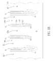
- FIGS. 1A-7Care schematic diagrams illustrating a method for fabricating a memory device with buried digit lines and buried word lines integrated in a memory array of the memory device in accordance with one embodiment of the present invention, wherein:
- FIGS. 1A-7Aare top views of schematic layout diagrams of a memory array of the memory device in different manufacturing stages according to an exemplary embodiment of the invention.
- FIGS. 1B-7B and 1C-7Care schematic, cross-sectional views taken along lines I-I′ and II-II′, respectively, in the layout diagrams depicted in FIGS. 1A-7A .
- wafer and substrateused herein include any structure having an exposed surface onto which a layer is deposited according to the present invention, for example, to form the integrated circuit (IC) structure.
- substrateis understood to include semiconductor wafers.
- substrateis also used to refer to semiconductor structures during processing, and may include other layers that have been fabricated thereupon. Both wafer and substrate include doped and undoped semiconductors, epitaxial semiconductor layers supported by a base semiconductor or insulator, as well as other semiconductor structures well known to one skilled in the art.
- horizontalas used herein is defined as a plane parallel to the conventional major plane or surface of the semiconductor substrate, regardless of its orientation.
- verticalrefers to a direction perpendicular to the horizontal as just defined. Terms, such as “on,” “above,” “below,” “bottom,” “top,” “side” (as in “sidewall”), “higher,” “lower,” “over,” and “under,” are defined with respect to the horizontal plane.
- the present inventionpertains to an improved DRAM device that is comprised of a plurality of memory cells having an effective cell size of 6F 2 (e.g., 3F ⁇ 2F) and an enlarged cell contact area.
- the enlarged cell contact areainvolves the use of inventive self-constrained epitaxial growth technology, which effectively avoids shorting between neighboring cells.
- the width of the featureis also referred to as the CD or minimum feature size (“F”) of the line.
- the CDis typically the smallest geometrical feature, such as the width of an interconnect line, contact, or trench, that is formed during IC manufacturing using a given technology, such as photolithography.
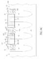
- FIG. 1Ais a top view of the schematic layout of the memory array of the memory device after the formation of columns of buried word lines (BWLs) according to one embodiment of the invention.
- FIGS. 1B and 1Care schematic, cross-sectional views taken along lines I-I′ and II-II′, respectively, in FIG. 1A .
- a semiconductor substrate 10such as a silicon wafer is provided.
- a plurality of active areas 12is formed in the semiconductor substrate 10 .
- Shallow trench isolation (STI) structures 14are provided between the active areas 12 to isolate active areas 12 from one another. The formation of the STI structures 14 is known in the art.
- STI structure described hereinmay include additional features than those known in the art.
- a photoresist pattern(not shown) may be formed on the semiconductor substrate 10 , which defines trench patterns to be etched into the semiconductor substrate 10 .
- a dry etching processis performed to etch the semiconductor substrate 10 to thereby form trenches.
- the trenchesare then filled with insulating materials such as silicon oxide.
- the longitudinal direction of each active area 12extends along a reference AA direction.
- Each active area 12has a longer side that is in parallel with the longitudinal direction of each active area 12 .
- An included angle (acute angle) ⁇ between the reference AA direction and a reference x-axis directionmay range between 15° and 60°, but should not be limited thereto.
- columns of line-shaped buried word lines 16are fabricated in the semiconductor substrate 10 .
- the columns of line-shaped buried word lines 16extend along a reference y-axis, and two buried word lines 16 intersect with each active area 12 , thereby separating each active area into three portions including a digit line contact area 12 a and two cell contact areas (or capacitor landing areas) 12 b .
- the two cell contact areas 12 bare located at two distal ends of each active area 12
- the digit line contact area 12 ais between two line-shaped buried word lines 16 .
- each of the buried word lines 16includes a conductive portion 162 embedded at a lower portion of a word line trench 160 .
- the conductive portion 162may comprise a layer of metal, metal composite or layers of conductive materials.
- the conductive portion 162may comprise titanium nitride (TiN), titanium/titanium nitride (Ti/TiN), tungsten nitride (WN), tungsten/tungsten nitride (W/WN), tantalum nitride (TaN), tantalum/tantalum nitride (Ta/TaN), titanium silicon nitride (TiSiN), tantalum silicon nitride (TaSiN), and tungsten silicon nitride (WSiN), or a combination thereof.
- TiNtitanium nitride
- Ti/TiNtitanium/titanium nitride
- WNtungsten nitride
- W/WNtungsten/tungsten nitride
- TaNtantalum nitride
- Ta/TaNtantalum/tantalum nitride
- TiSiNtitanium silicon nitride
- the conductive portion 162is encapsulated by an insulating layer 164 such as silicon oxide lining an interior surface of the word line trench 160 and a cap layer 166 situated atop the conductive portion 162 .
- the cap layer 166has a top surface that is flush with a top surface 10 a of the semiconductor substrate 10 .
- the cap layer 166may comprise silicon nitride, but is not limited thereto.
- FIG. 2Ais a top view of the schematic layout of the memory array of the memory device after the formation of buried digit line (BDL) trenches according to one embodiment of the invention.
- FIGS. 2B and 2Care schematic, cross-sectional views taken along lines I-I′ and II-II′, respectively, in FIG. 2A .
- rows of BDL trenches 22are formed and are recessed into the top surface 10 a of the semiconductor substrate 10 .
- the rows of BDL trenches 22extend along the reference x-axis and intersect with the active areas 12 at the included angle ⁇ , thereby exposing the digit line contact area 12 a of each active area 12 .
- each of the BDL trenches 22is well controlled such that the conductive portion 162 of each buried word line 16 is not exposed.
- a conformal liner layer 210such as a silicon nitride liner is blanket-deposited into each BDL trench 22 , but does not completely fill up the BDL trench 22 .
- the liner layer 210may be deposited using chemical vapor deposition (CVD) or atomic layer deposition (ALD) methods, but is not limited thereto. In some embodiments, the liner layer 210 may cover the area outside the BDL trenches 22 .
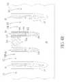
- FIG. 3Ais a top view of the schematic layout of the memory array of the memory device after the formation of digit line contact openings in the photoresist layer according to the embodiment of the invention.
- FIGS. 3B and 3Care schematic, cross-sectional views taken along lines I-I′ and II-II′, respectively, in FIG. 3A .
- a photoresist layer 30is formed over the semiconductor substrate 10 .
- a plurality of openings 302is formed in the photoresist layer 30 to expose portions of the liner layer 210 in respective digit line contact areas 12 a where the line-shaped BDL trenches 22 intersect with each of the active areas 12 .
- the openings 302are aligned with the digit line contact areas 12 a to thereby expose only the portions of the liner layer 210 , which are situated directly above the digit line contact areas 12 a .
- an etching processis performed to etch away the exposed portions of the liner layer 210 through the openings 302 , thereby exposing surfaces of the semiconductor substrate 10 within the digit line contact areas 12 a .
- the remaining photoresist layer 30is removed.
- FIG. 4Ais a top view of the schematic layout of the memory array of the memory device after filling the BDL trenches 22 with metal according to the embodiment of the invention.
- FIGS. 4B and 4Care schematic, cross-sectional views taken along lines I-I′ and II-II′, respectively, in FIG. 4A .
- a metal layer 220comprising, for example, Ti, TiN or W, is deposited into the BDL trenches 22 .
- the metal layer 220is insulated from the active areas 12 by the liner layer 210 except for the surface of the semiconductor substrate 10 within the digit line contact areas 12 a . As can be seen in FIGS. 4B and 4C , the metal layer 220 is electrically connected to the semiconductor substrate 10 within the digit line contact areas 12 a . According to the embodiment, the BDL trenches 22 are completely filled up with the metal layer 220 . By performing suitable processes such as etching or polishing, a top surface of the metal layer 220 is flush with the top surface 10 a of the substrate 10 , the top surface of the cap layer 166 and the top surface of the STI structures 14 .
- FIG. 5Ais a top view of the schematic layout of the memory array of the memory device after forming a cap layer 230 atop the metal layer 220 according to the embodiment of the invention.
- FIGS. 5B and 5Care schematic, cross-sectional views taken along lines I-I′ and II-II′, respectively, in FIG. 5A .
- the top surface of the metal layer 220is recessed to a lower level that is lower than the top surface 10 a of the semiconductor substrate 10 .
- the metal layer 220is capped with a cap layer 230 .
- the cap layer 230may be a silicon nitride cap layer, but is not limited thereto.
- a silicon nitride layer(not shown) may be deposited over the semiconductor substrate 10 in a blanket manner. The silicon nitride layer completely fills up the recess above the metal layer 220 .
- a chemical-mechanical polishing (CMP) processmay be performed to remove excess silicon nitride layer outside the BDL trenches 22 .
- each of the square areas 40is surrounded by the SiN liner layer 210 and SiN cap layer 230 in the BDL trenches 22 in the reference x-axis direction, and the SiN cap layer 166 in the reference y-axis direction.
- the cell contact area 12 b of the active area 12is exposed. It is desirable to provide a larger cell contact area in order to improve the cell contact Rc.
- the SiN surrounded square areas 40constitute self-constrained epitaxial growth regions for following cell contact area enlargement.
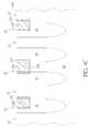
- FIG. 6Ais a top view of the schematic layout of the memory array of the memory device after oxide recess and epitaxial growth in the square areas 40 , according to the embodiment of the invention.
- FIGS. 6B and 6Care schematic, cross-sectional views taken along lines I-I′ and II-II′, respectively, in FIG. 6A .
- an etching (oxide recess) processis performed to selectively etch away an upper portion of the STI structures 14 from each of the square areas 40 .
- the silicon oxide layer of the STI structures 14may be etched by using, for example, diluted HF (DHF) or the like, which is selective to the surrounding silicon nitride cap layers and silicon.
- DHFdiluted HF
- the selective etching of the silicon oxide layer of the STI structures 14may be carried out using other suitable methods, for example, a dry etching process.
- an L-shaped recessed area 420 having a step height his formed within each of the square areas 40 .
- two adjacent sidewalls 122 and 124 of the cell contact area 12 b ( FIG. 5A ) of the active area 12are exposed.
- an epitaxial silicon growth processis performed to grow an epitaxial silicon layer 52 from the exposed cell contact area 12 b ( FIG. 5A ) and the sidewalls 122 and 124 , thereby forming an enlarged cell contact area 12 b ′.
- the epitaxial silicon layer 52may function as a landing pad for a capacitor.
- the epitaxial silicon growthis confined to each square area 40 that is surrounded by the SiN cap layers extending along the reference x-axis direction and the reference y-axis direction. Therefore, shorting between adjacent cells can be avoided. It is understood that prior to the epitaxial silicon growth process, the major surface 10 a of the semiconductor substrate 10 may be subjected to a pre-clean process.
- the L-shaped recessed area 420is not filled up with the epitaxial silicon layer 52 , leaving a gap between the epitaxial silicon layer 52 and the adjacent BDL trenches 22 and the BWL trenches 160 ( FIG. 6B ). However, it is understood that in other embodiments, the L-shaped recessed area 420 may be completely filled up with the epitaxial silicon layer.
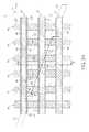
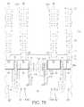
- FIG. 7Ais a top view of the schematic layout of the memory array of the memory device after forming a dielectric stack and capacitors according to the embodiment of the invention.
- FIGS. 7B and 7Care schematic, cross-sectional views taken along lines I-I′ and II-II′, respectively, in FIG. 7A .
- a dielectric stack 70may be deposited over the major surface 10 a of the semiconductor substrate 10 .
- the dielectric stack 70may include, but is not limited to, an etch stop layer 71 , an inter-layer dielectric 72 , an intermediate layer 73 , an inter-layer dielectric 74 , and a cap layer 75 .
- the etch stop layer 71may comprise silicon nitride, but is not limited thereto.
- the inter-layer dielectric 72 and the inter-layer dielectric 74may comprise phosphosilicate glass (PSG), borophosphosilicate glass (BPSG), silicon oxide, or low-k materials, but is not limited thereto.
- the cap layer 75may comprise silicon nitride or silicon oxy-nitride, but is not limited thereto.
- the etch stop layer 71conformally covers the cap layer 166 , the exposed surface of the liner layer 210 within the L-shaped recessed area 420 , the epitaxial silicon layer 52 , and the STI structure 14 .
- capacitor trenches 810are formed in the dielectric stack 70 by using, for example, a dry etching process. A bottom of each capacitor trench 810 exposes a portion of each epitaxial silicon layer 52 . A capacitor 80 is then formed within each capacitor trench 810 .
- the capacitor 80may comprise a bottom electrode, a capacitor dielectric layer, and a top electrode. The detailed structure of the capacitor 80 is not explicitly shown.
Landscapes
- Engineering & Computer Science (AREA)
- Manufacturing & Machinery (AREA)
- Semiconductor Memories (AREA)
- Power Engineering (AREA)
- Physics & Mathematics (AREA)
- Condensed Matter Physics & Semiconductors (AREA)
- General Physics & Mathematics (AREA)
- Computer Hardware Design (AREA)
- Microelectronics & Electronic Packaging (AREA)
- Internal Circuitry In Semiconductor Integrated Circuit Devices (AREA)
Abstract
Description
Claims (10)
Priority Applications (7)
| Application Number | Priority Date | Filing Date | Title |
|---|---|---|---|
| US15/002,401US9859284B2 (en) | 2016-01-21 | 2016-01-21 | Semiconductor memory device having enlarged cell contact area and method of fabricating the same |
| KR1020160022059AKR20170087803A (en) | 2016-01-21 | 2016-02-24 | Semiconductor memory device having enlarged cell contact area and method of fabricating the same |
| TW105108230ATWI621245B (en) | 2016-01-21 | 2016-03-17 | Semiconductor memory device with increased memory cell contact area and manufacturing method thereof |
| CN201610595350.6ACN106992156B (en) | 2016-01-21 | 2016-07-26 | Memory array and its manufacturing method |
| CN201910775074.5ACN110634869B (en) | 2016-01-21 | 2016-07-26 | Memory array and method of manufacturing the same |
| US15/253,894US9859285B2 (en) | 2016-01-21 | 2016-09-01 | Method of fabricating semiconductor memory device having enlarged cell contact area |
| US15/829,420US10847518B2 (en) | 2016-01-21 | 2017-12-01 | Semiconductor devices, memory dies and related methods |
Applications Claiming Priority (1)
| Application Number | Priority Date | Filing Date | Title |
|---|---|---|---|
| US15/002,401US9859284B2 (en) | 2016-01-21 | 2016-01-21 | Semiconductor memory device having enlarged cell contact area and method of fabricating the same |
Related Child Applications (1)
| Application Number | Title | Priority Date | Filing Date |
|---|---|---|---|
| US15/253,894DivisionUS9859285B2 (en) | 2016-01-21 | 2016-09-01 | Method of fabricating semiconductor memory device having enlarged cell contact area |
Publications (2)
| Publication Number | Publication Date |
|---|---|
| US20170213834A1 US20170213834A1 (en) | 2017-07-27 |
| US9859284B2true US9859284B2 (en) | 2018-01-02 |
Family
ID=59359487
Family Applications (3)
| Application Number | Title | Priority Date | Filing Date |
|---|---|---|---|
| US15/002,401ActiveUS9859284B2 (en) | 2016-01-21 | 2016-01-21 | Semiconductor memory device having enlarged cell contact area and method of fabricating the same |
| US15/253,894ActiveUS9859285B2 (en) | 2016-01-21 | 2016-09-01 | Method of fabricating semiconductor memory device having enlarged cell contact area |
| US15/829,420ActiveUS10847518B2 (en) | 2016-01-21 | 2017-12-01 | Semiconductor devices, memory dies and related methods |
Family Applications After (2)
| Application Number | Title | Priority Date | Filing Date |
|---|---|---|---|
| US15/253,894ActiveUS9859285B2 (en) | 2016-01-21 | 2016-09-01 | Method of fabricating semiconductor memory device having enlarged cell contact area |
| US15/829,420ActiveUS10847518B2 (en) | 2016-01-21 | 2017-12-01 | Semiconductor devices, memory dies and related methods |
Country Status (4)
| Country | Link |
|---|---|
| US (3) | US9859284B2 (en) |
| KR (1) | KR20170087803A (en) |
| CN (2) | CN110634869B (en) |
| TW (1) | TWI621245B (en) |
Cited By (6)
| Publication number | Priority date | Publication date | Assignee | Title |
|---|---|---|---|---|
| US11121134B2 (en)* | 2019-09-27 | 2021-09-14 | Samsung Electronics Co., Ltd. | Semiconductor device and method of fabricating the same |
| US11482446B1 (en) | 2020-07-27 | 2022-10-25 | Changxin Memory Technologies, Inc. | Method for manufacturing semiconductor device and semiconductor device |
| US11871555B2 (en) | 2020-05-18 | 2024-01-09 | Changxin Memory Technologies, Inc. | Semiconductor structure and method for forming semiconductor structure |
| US12120868B2 (en) | 2020-11-12 | 2024-10-15 | Changxin Memory Technologies, Inc. | Semiconductor device with buried bit line and preparation method thereof |
| US12185527B2 (en) | 2020-08-05 | 2024-12-31 | Changxin Memory Technologies, Inc. | Semiconductor structure comprising a word line with convex portions and manufacturing method thereof |
| US12213309B2 (en) | 2020-10-15 | 2025-01-28 | Changxin Memory Technologies, Inc. | Semiconductor device and manufacturing method thereof |
Families Citing this family (39)
| Publication number | Priority date | Publication date | Assignee | Title |
|---|---|---|---|---|
| US9859284B2 (en) | 2016-01-21 | 2018-01-02 | Micron Technology, Inc. | Semiconductor memory device having enlarged cell contact area and method of fabricating the same |
| CN107680963A (en)* | 2017-10-09 | 2018-02-09 | 睿力集成电路有限公司 | Dynamic random access memory array and its domain structure, preparation method |
| CN107634103B (en) | 2017-10-24 | 2018-10-16 | 睿力集成电路有限公司 | Memory transistor and forming method thereof, semiconductor devices |
| CN107946232B (en)* | 2017-12-01 | 2023-05-26 | 长鑫存储技术有限公司 | Shallow trench isolation structure array, semiconductor device structure and preparation method |
| CN107994018B (en)* | 2017-12-27 | 2024-03-29 | 长鑫存储技术有限公司 | Semiconductor memory device structure and method for manufacturing the same |
| CN110299324B (en)* | 2018-03-22 | 2024-03-26 | 长鑫存储技术有限公司 | Transistor structure of semiconductor memory and method for manufacturing the same |
| CN110534150B (en)* | 2018-05-25 | 2021-06-11 | 华邦电子股份有限公司 | Memory device and method of manufacturing the same |
| US10535378B1 (en)* | 2018-07-19 | 2020-01-14 | Micron Technology, Inc. | Integrated assemblies which include non-conductive-semiconductor-material and conductive-semiconductor-material, and methods of forming integrated assemblies |
| US10438953B1 (en)* | 2018-07-24 | 2019-10-08 | Micron Technology, Inc. | Integrated circuitry construction, a DRAM construction, and a method used in forming an integrated circuitry construction |
| CN110943045B (en)* | 2018-09-21 | 2024-09-13 | 长鑫存储技术有限公司 | Semiconductor structure and preparation method thereof |
| US11152371B2 (en)* | 2019-08-13 | 2021-10-19 | Micron Technology, Inc. | Apparatus comprising monocrystalline semiconductor materials and monocrystalline metal silicide materials, and related methods, electronic devices, and electronic systems |
| CN112652622B (en)* | 2019-10-09 | 2025-02-25 | 长鑫存储技术有限公司 | Semiconductor memory, semiconductor structure and manufacturing method thereof |
| KR102753885B1 (en)* | 2019-10-24 | 2025-01-15 | 삼성전자주식회사 | Semiconductor memory device and Method of fabricating the same |
| US10998321B1 (en)* | 2019-10-28 | 2021-05-04 | Nanya Technology Corporation | Semiconductor device having a stacked nanowire structure disposed over a buried word line and method of manufacturing the same |
| KR102748982B1 (en)* | 2019-10-30 | 2025-01-02 | 삼성전자주식회사 | Semiconductor devices and methods of manufacturing the same |
| CN113130491B (en)* | 2020-01-15 | 2023-10-17 | 华邦电子股份有限公司 | Memory device and method of manufacturing the same |
| CN211182204U (en)* | 2020-01-21 | 2020-08-04 | 福建省晋华集成电路有限公司 | Memory device |
| CN113284896B (en)* | 2020-02-20 | 2024-06-21 | 华邦电子股份有限公司 | Word line structure, storage element and manufacturing method thereof |
| US11862697B2 (en) | 2020-04-30 | 2024-01-02 | Changxin Memory Technologies, Inc. | Method for manufacturing buried gate and method for manufacturing semiconductor device |
| CN113690185B (en)* | 2020-05-18 | 2023-09-29 | 长鑫存储技术有限公司 | Semiconductor structure and forming method thereof |
| KR102763816B1 (en)* | 2020-07-02 | 2025-02-05 | 삼성전자주식회사 | Semiconductor memory device and method for fabricating the same |
| US11056175B1 (en)* | 2020-07-28 | 2021-07-06 | Winbond Electronics Corp. | Semiconductor device and manufacturing method thereof |
| US11792973B2 (en) | 2020-07-28 | 2023-10-17 | Changxin Memory Technologies, Inc. | Storage device and forming method having a strip-shaped bitline contact structure |
| CN114068547B (en)* | 2020-08-05 | 2025-01-21 | 长鑫存储技术有限公司 | Semiconductor structure and method for manufacturing semiconductor structure |
| US11877440B2 (en) | 2020-10-15 | 2024-01-16 | Changxin Memory Technologies, Inc. | Bit line structure including ohmic contact and forming method thereof |
| US11264391B1 (en)* | 2020-10-15 | 2022-03-01 | Nanya Technology Corporation | Semiconductor structure and manufacturing method thereof |
| EP4287256A4 (en)* | 2021-03-05 | 2024-08-28 | Changxin Memory Technologies, Inc. | SEMICONDUCTOR STRUCTURE AND ITS MANUFACTURING METHOD |
| CN113097149B (en)* | 2021-03-31 | 2022-05-24 | 长鑫存储技术有限公司 | Semiconductor structure and method of making the same |
| TWI779627B (en)* | 2021-05-25 | 2022-10-01 | 南亞科技股份有限公司 | Semiconductor structure and method of fabricating the same |
| KR20220167057A (en)* | 2021-06-11 | 2022-12-20 | 에스케이하이닉스 주식회사 | Semiconductor device and method for manufacturing the same |
| US11991876B2 (en) | 2021-07-07 | 2024-05-21 | Changxin Memory Technologies, Inc. | Method for forming a semiconductor structure having second isolation structures located between adjacent active areas |
| CN113725166B (en)* | 2021-09-02 | 2023-10-27 | 长鑫存储技术有限公司 | Semiconductor structure preparation method and semiconductor structure |
| TWI865124B (en)* | 2021-11-17 | 2024-12-01 | 南亞科技股份有限公司 | Method for preparing memory array with contact enhancement cap |
| US11917813B2 (en) | 2021-11-17 | 2024-02-27 | Nanya Technology Corporation | Memory array with contact enhancement cap and method for preparing the memory array |
| CN114068556B (en)* | 2021-11-19 | 2025-08-15 | 福建省晋华集成电路有限公司 | Semiconductor memory device and method for manufacturing the same |
| US12035519B2 (en)* | 2021-11-19 | 2024-07-09 | Fujian Jinhua Integrated Circuit Co., Ltd. | Semiconductor memory device and method for forming the same |
| US20230262965A1 (en)* | 2022-02-17 | 2023-08-17 | Nanya Technology Corporation | Memory structure and method of forming thereof |
| CN114784005B (en)* | 2022-03-10 | 2025-08-19 | 福建省晋华集成电路有限公司 | Semiconductor memory device with a memory cell having a memory cell with a memory cell having a memory cell |
| CN116193856B (en)* | 2023-04-23 | 2023-10-17 | 长鑫存储技术有限公司 | Semiconductor structure and preparation method thereof |
Citations (11)
| Publication number | Priority date | Publication date | Assignee | Title |
|---|---|---|---|---|
| US5753947A (en) | 1995-01-20 | 1998-05-19 | Micron Technology, Inc. | Very high-density DRAM cell structure and method for fabricating it |
| US20020052077A1 (en) | 2000-10-30 | 2002-05-02 | Chartered Semiconductor Manufacturing Ltd. | Low-leakage dram structures using selective silicon epitaxial growth (seg) on an insulating layer |
| US6734482B1 (en) | 2002-11-15 | 2004-05-11 | Micron Technology, Inc. | Trench buried bit line memory devices |
| US20060043450A1 (en) | 2004-09-02 | 2006-03-02 | Tang Sanh D | Vertical transistors |
| US20110037111A1 (en)* | 2009-08-11 | 2011-02-17 | Hynix Semiconductor Inc. | Semiconductor device and method of fabricating the same |
| US20110156118A1 (en)* | 2009-12-30 | 2011-06-30 | Jung-Woo Park | Semiconductor device with vertical cells and fabrication method thereof |
| US20120217559A1 (en) | 2011-02-28 | 2012-08-30 | Samsung Electronics Co., Ltd. | Semiconductor memory device |
| KR20120119093A (en) | 2011-04-20 | 2012-10-30 | 삼성전자주식회사 | Semiconductor device |
| US20130015551A1 (en)* | 2011-07-14 | 2013-01-17 | Kuo-Chen Wang | Method for fabricating memory device with buried digit lines and buried word lines |
| KR20140052729A (en) | 2012-10-25 | 2014-05-07 | 삼성전자주식회사 | Semiconductor devices having recessed active regions and methods for fabricating the same |
| US20140159194A1 (en) | 2012-12-10 | 2014-06-12 | Samsung Electronics Co., Ltd. | Semiconductor device |
Family Cites Families (6)
| Publication number | Priority date | Publication date | Assignee | Title |
|---|---|---|---|---|
| KR101095817B1 (en)* | 2009-02-10 | 2011-12-21 | 주식회사 하이닉스반도체 | Semiconductor element and manufacturing method thereof |
| US8143121B2 (en)* | 2009-10-01 | 2012-03-27 | Nanya Technology Corp. | DRAM cell with double-gate fin-FET, DRAM cell array and fabrication method thereof |
| CN102184980B (en) | 2011-04-02 | 2013-10-30 | 中国科学院苏州纳米技术与纳米仿生研究所 | Wafer-bonding-based triple-junction solar cell and preparation method thereof |
| US8648414B2 (en)* | 2011-07-01 | 2014-02-11 | Micron Technology, Inc. | Semiconductor structures including bodies of semiconductor material, devices including such structures and related methods |
| US9589964B1 (en)* | 2015-06-24 | 2017-03-07 | Samsung Electronics Co., Ltd. | Methods of fabricating semiconductor devices |
| US9859284B2 (en) | 2016-01-21 | 2018-01-02 | Micron Technology, Inc. | Semiconductor memory device having enlarged cell contact area and method of fabricating the same |
- 2016
- 2016-01-21USUS15/002,401patent/US9859284B2/enactiveActive
- 2016-02-24KRKR1020160022059Apatent/KR20170087803A/ennot_activeCeased
- 2016-03-17TWTW105108230Apatent/TWI621245B/enactive
- 2016-07-26CNCN201910775074.5Apatent/CN110634869B/enactiveActive
- 2016-07-26CNCN201610595350.6Apatent/CN106992156B/enactiveActive
- 2016-09-01USUS15/253,894patent/US9859285B2/enactiveActive
- 2017
- 2017-12-01USUS15/829,420patent/US10847518B2/enactiveActive
Patent Citations (11)
| Publication number | Priority date | Publication date | Assignee | Title |
|---|---|---|---|---|
| US5753947A (en) | 1995-01-20 | 1998-05-19 | Micron Technology, Inc. | Very high-density DRAM cell structure and method for fabricating it |
| US20020052077A1 (en) | 2000-10-30 | 2002-05-02 | Chartered Semiconductor Manufacturing Ltd. | Low-leakage dram structures using selective silicon epitaxial growth (seg) on an insulating layer |
| US6734482B1 (en) | 2002-11-15 | 2004-05-11 | Micron Technology, Inc. | Trench buried bit line memory devices |
| US20060043450A1 (en) | 2004-09-02 | 2006-03-02 | Tang Sanh D | Vertical transistors |
| US20110037111A1 (en)* | 2009-08-11 | 2011-02-17 | Hynix Semiconductor Inc. | Semiconductor device and method of fabricating the same |
| US20110156118A1 (en)* | 2009-12-30 | 2011-06-30 | Jung-Woo Park | Semiconductor device with vertical cells and fabrication method thereof |
| US20120217559A1 (en) | 2011-02-28 | 2012-08-30 | Samsung Electronics Co., Ltd. | Semiconductor memory device |
| KR20120119093A (en) | 2011-04-20 | 2012-10-30 | 삼성전자주식회사 | Semiconductor device |
| US20130015551A1 (en)* | 2011-07-14 | 2013-01-17 | Kuo-Chen Wang | Method for fabricating memory device with buried digit lines and buried word lines |
| KR20140052729A (en) | 2012-10-25 | 2014-05-07 | 삼성전자주식회사 | Semiconductor devices having recessed active regions and methods for fabricating the same |
| US20140159194A1 (en) | 2012-12-10 | 2014-06-12 | Samsung Electronics Co., Ltd. | Semiconductor device |
Non-Patent Citations (4)
| Title |
|---|
| Furumura, "Selective Growth of Polysilicon", J. Electrochem. Soc.: Solid State Science and Technology, Feb. 1986, pp. 379-383. |
| Korean Written Opinion from Korean Application No. 10-2016-0022059, dated Aug. 1, 2017, 7 pages with English translation. |
| Notice of Reasons for Rejection from Korean Application No. 10-2016-0022059, dated Jun. 1, 2017, 14 pages with English translation. |
| Taiwanese Office Action, dated Sep. 8, 2017, and Search Report, dated Sep. 1, 2017 for Taiwanese Application No. 105108230, 10 pages with English translation. |
Cited By (8)
| Publication number | Priority date | Publication date | Assignee | Title |
|---|---|---|---|---|
| US11121134B2 (en)* | 2019-09-27 | 2021-09-14 | Samsung Electronics Co., Ltd. | Semiconductor device and method of fabricating the same |
| US20210408004A1 (en)* | 2019-09-27 | 2021-12-30 | Samsung Electronics Co., Ltd. | Semiconductor device and method of fabricating the same |
| US11594538B2 (en)* | 2019-09-27 | 2023-02-28 | Samsung Electronics Co., Ltd. | Semiconductor device and method of fabricating the same |
| US11871555B2 (en) | 2020-05-18 | 2024-01-09 | Changxin Memory Technologies, Inc. | Semiconductor structure and method for forming semiconductor structure |
| US11482446B1 (en) | 2020-07-27 | 2022-10-25 | Changxin Memory Technologies, Inc. | Method for manufacturing semiconductor device and semiconductor device |
| US12185527B2 (en) | 2020-08-05 | 2024-12-31 | Changxin Memory Technologies, Inc. | Semiconductor structure comprising a word line with convex portions and manufacturing method thereof |
| US12213309B2 (en) | 2020-10-15 | 2025-01-28 | Changxin Memory Technologies, Inc. | Semiconductor device and manufacturing method thereof |
| US12120868B2 (en) | 2020-11-12 | 2024-10-15 | Changxin Memory Technologies, Inc. | Semiconductor device with buried bit line and preparation method thereof |
Also Published As
| Publication number | Publication date |
|---|---|
| CN110634869A (en) | 2019-12-31 |
| TWI621245B (en) | 2018-04-11 |
| US20180083011A1 (en) | 2018-03-22 |
| US9859285B2 (en) | 2018-01-02 |
| US20170213837A1 (en) | 2017-07-27 |
| US10847518B2 (en) | 2020-11-24 |
| KR20170087803A (en) | 2017-07-31 |
| CN106992156A (en) | 2017-07-28 |
| US20170213834A1 (en) | 2017-07-27 |
| CN110634869B (en) | 2023-09-26 |
| CN106992156B (en) | 2019-09-13 |
| TW201727874A (en) | 2017-08-01 |
Similar Documents
| Publication | Publication Date | Title |
|---|---|---|
| US10847518B2 (en) | Semiconductor devices, memory dies and related methods | |
| US10566332B2 (en) | Semiconductor devices | |
| US10475794B1 (en) | Semiconductor device and method for fabricating the same | |
| US10825818B2 (en) | Method of forming semiconductor device | |
| US10573652B2 (en) | Semiconductor device and method for fabricating the same | |
| US8691680B2 (en) | Method for fabricating memory device with buried digit lines and buried word lines | |
| US10770464B2 (en) | Semiconductor device including bit line structure of dynamic random access memory (DRAM) and method for fabricating the same | |
| US9230966B2 (en) | Capacitor and method of manufacturing the same | |
| US20120205779A1 (en) | Semiconductor devices including capacitors and metal contacts, and methods of fabricating the same | |
| US20120217576A1 (en) | Semiconductor device and method for forming the same | |
| US9018733B1 (en) | Capacitor, storage node of the capacitor, and method of forming the same | |
| US8704283B2 (en) | Semiconductor devices | |
| US20230146151A1 (en) | Semiconductor devices | |
| US11665888B2 (en) | Semiconductor device and method for fabricating the same | |
| US20250267854A1 (en) | Semiconductor devices including bit lines | |
| US20250220886A1 (en) | Semiconductor structure and method for forming the same | |
| CN115643756A (en) | Conductive layer in memory array region and method for forming the same |
Legal Events
| Date | Code | Title | Description |
|---|---|---|---|
| AS | Assignment | Owner name:INOTERA MEMORIES, INC., TAIWAN Free format text:ASSIGNMENT OF ASSIGNORS INTEREST;ASSIGNOR:WANG, KUO-CHEN;REEL/FRAME:037539/0991 Effective date:20160119 | |
| AS | Assignment | Owner name:MORGAN STANLEY SENIOR FUNDING, INC., MARYLAND Free format text:SUPPLEMENT NO. 3 TO PATENT SECURITY AGREEMENT;ASSIGNOR:MICRON TECHNOLOGY, INC.;REEL/FRAME:041675/0105 Effective date:20170124 | |
| AS | Assignment | Owner name:MICRON TECHNOLOGY, INC., IDAHO Free format text:ASSIGNMENT OF ASSIGNORS INTEREST;ASSIGNOR:INOTERA MEMORIES, INC.;REEL/FRAME:041820/0815 Effective date:20170222 | |
| STCF | Information on status: patent grant | Free format text:PATENTED CASE | |
| AS | Assignment | Owner name:JPMORGAN CHASE BANK, N.A., AS COLLATERAL AGENT, ILLINOIS Free format text:SECURITY INTEREST;ASSIGNORS:MICRON TECHNOLOGY, INC.;MICRON SEMICONDUCTOR PRODUCTS, INC.;REEL/FRAME:047540/0001 Effective date:20180703 Owner name:JPMORGAN CHASE BANK, N.A., AS COLLATERAL AGENT, IL Free format text:SECURITY INTEREST;ASSIGNORS:MICRON TECHNOLOGY, INC.;MICRON SEMICONDUCTOR PRODUCTS, INC.;REEL/FRAME:047540/0001 Effective date:20180703 | |
| AS | Assignment | Owner name:MICRON TECHNOLOGY, INC., IDAHO Free format text:RELEASE BY SECURED PARTY;ASSIGNOR:MORGAN STANLEY SENIOR FUNDING, INC., AS COLLATERAL AGENT;REEL/FRAME:050695/0825 Effective date:20190731 | |
| AS | Assignment | Owner name:MICRON TECHNOLOGY, INC., IDAHO Free format text:RELEASE BY SECURED PARTY;ASSIGNOR:JPMORGAN CHASE BANK, N.A., AS COLLATERAL AGENT;REEL/FRAME:051028/0001 Effective date:20190731 Owner name:MICRON SEMICONDUCTOR PRODUCTS, INC., IDAHO Free format text:RELEASE BY SECURED PARTY;ASSIGNOR:JPMORGAN CHASE BANK, N.A., AS COLLATERAL AGENT;REEL/FRAME:051028/0001 Effective date:20190731 | |
| MAFP | Maintenance fee payment | Free format text:PAYMENT OF MAINTENANCE FEE, 4TH YEAR, LARGE ENTITY (ORIGINAL EVENT CODE: M1551); ENTITY STATUS OF PATENT OWNER: LARGE ENTITY Year of fee payment:4 | |
| MAFP | Maintenance fee payment | Free format text:PAYMENT OF MAINTENANCE FEE, 8TH YEAR, LARGE ENTITY (ORIGINAL EVENT CODE: M1552); ENTITY STATUS OF PATENT OWNER: LARGE ENTITY Year of fee payment:8 |