US9859060B1 - Capacitor with multiple elements for multiple replacement applications - Google Patents
Capacitor with multiple elements for multiple replacement applicationsDownload PDFInfo
- Publication number
- US9859060B1 US9859060B1US15/426,858US201715426858AUS9859060B1US 9859060 B1US9859060 B1US 9859060B1US 201715426858 AUS201715426858 AUS 201715426858AUS 9859060 B1US9859060 B1US 9859060B1
- Authority
- US
- United States
- Prior art keywords
- capacitor
- cover
- terminal
- terminals
- capacitive elements
- Prior art date
- Legal status (The legal status is an assumption and is not a legal conclusion. Google has not performed a legal analysis and makes no representation as to the accuracy of the status listed.)
- Active
Links
Images


Classifications
- H—ELECTRICITY
- H01—ELECTRIC ELEMENTS
- H01G—CAPACITORS; CAPACITORS, RECTIFIERS, DETECTORS, SWITCHING DEVICES, LIGHT-SENSITIVE OR TEMPERATURE-SENSITIVE DEVICES OF THE ELECTROLYTIC TYPE
- H01G4/00—Fixed capacitors; Processes of their manufacture
- H01G4/38—Multiple capacitors, i.e. structural combinations of fixed capacitors
- H01G4/385—Single unit multiple capacitors, e.g. dual capacitor in one coil
- H—ELECTRICITY
- H01—ELECTRIC ELEMENTS
- H01G—CAPACITORS; CAPACITORS, RECTIFIERS, DETECTORS, SWITCHING DEVICES, LIGHT-SENSITIVE OR TEMPERATURE-SENSITIVE DEVICES OF THE ELECTROLYTIC TYPE
- H01G2/00—Details of capacitors not covered by a single one of groups H01G4/00-H01G11/00
- H01G2/08—Cooling arrangements; Heating arrangements; Ventilating arrangements
- H—ELECTRICITY
- H01—ELECTRIC ELEMENTS
- H01G—CAPACITORS; CAPACITORS, RECTIFIERS, DETECTORS, SWITCHING DEVICES, LIGHT-SENSITIVE OR TEMPERATURE-SENSITIVE DEVICES OF THE ELECTROLYTIC TYPE
- H01G2/00—Details of capacitors not covered by a single one of groups H01G4/00-H01G11/00
- H01G2/10—Housing; Encapsulation
- H01G2/103—Sealings, e.g. for lead-in wires; Covers
- H—ELECTRICITY
- H01—ELECTRIC ELEMENTS
- H01G—CAPACITORS; CAPACITORS, RECTIFIERS, DETECTORS, SWITCHING DEVICES, LIGHT-SENSITIVE OR TEMPERATURE-SENSITIVE DEVICES OF THE ELECTROLYTIC TYPE
- H01G2/00—Details of capacitors not covered by a single one of groups H01G4/00-H01G11/00
- H01G2/10—Housing; Encapsulation
- H01G2/106—Fixing the capacitor in a housing
- H—ELECTRICITY
- H01—ELECTRIC ELEMENTS
- H01G—CAPACITORS; CAPACITORS, RECTIFIERS, DETECTORS, SWITCHING DEVICES, LIGHT-SENSITIVE OR TEMPERATURE-SENSITIVE DEVICES OF THE ELECTROLYTIC TYPE
- H01G4/00—Fixed capacitors; Processes of their manufacture
- H01G4/002—Details
- H01G4/224—Housing; Encapsulation
- H—ELECTRICITY
- H01—ELECTRIC ELEMENTS
- H01G—CAPACITORS; CAPACITORS, RECTIFIERS, DETECTORS, SWITCHING DEVICES, LIGHT-SENSITIVE OR TEMPERATURE-SENSITIVE DEVICES OF THE ELECTROLYTIC TYPE
- H01G4/00—Fixed capacitors; Processes of their manufacture
- H01G4/002—Details
- H01G4/228—Terminals
- H—ELECTRICITY
- H01—ELECTRIC ELEMENTS
- H01G—CAPACITORS; CAPACITORS, RECTIFIERS, DETECTORS, SWITCHING DEVICES, LIGHT-SENSITIVE OR TEMPERATURE-SENSITIVE DEVICES OF THE ELECTROLYTIC TYPE
- H01G4/00—Fixed capacitors; Processes of their manufacture
- H01G4/002—Details
- H01G4/228—Terminals
- H01G4/232—Terminals electrically connecting two or more layers of a stacked or rolled capacitor
- H—ELECTRICITY
- H01—ELECTRIC ELEMENTS
- H01G—CAPACITORS; CAPACITORS, RECTIFIERS, DETECTORS, SWITCHING DEVICES, LIGHT-SENSITIVE OR TEMPERATURE-SENSITIVE DEVICES OF THE ELECTROLYTIC TYPE
- H01G4/00—Fixed capacitors; Processes of their manufacture
- H01G4/32—Wound capacitors
Definitions
- the disclosure hereinrelates to a capacitor with multiple capacitor values selectively connectable to match the capacitance or capacitances of one or more capacitors being replaced.
- capacitorsare used in connection with the motors of air-conditioning systems.
- the systemsoften employ two capacitors, one used in association with a compressor motor and another smaller value capacitor for use in association with a fan motor.
- Air-conditioning systems of different BTU capacitymade by different manufacturers or being a different model all may use capacitors having different values. These capacitors have a finite life and sometimes fail, causing the system to become inoperative.
- a serviceman making a service callusually will not know in advance whether a replacement capacitor is necessary to repair an air-conditioning system, or what value capacitor or capacitors might be needed to make the repair.
- One optionis for the serviceman to carry a large number of capacitors of different values in the service truck, but it is difficult and expensive to maintain such an inventory, especially because there can be a random need for several capacitors of the same value on the same day.
- the other optionis for the serviceman to return to the shop or visit a supplier to pick up a replacement capacitor of the required value. This is inefficient as the travel time to pick up parts greatly extends the overall time necessary to complete a repair. This is extremely detrimental if there is a backlog of inoperative air-conditioning systems on a hot day. This problem presents itself in connection with air-conditioning systems, but is also found in any situation where capacitors are used in association with motors and are replaced on service calls.
- Other typical examplesare refrigeration and heating systems, pumps, and manufacturing systems utilizing compressors.
- a desirable replacement capacitorwould have the electrical and physical characteristics of the failed capacitor, i.e. it should provide the same capacitance value or values at the same or higher voltage rating, be connectable using the same leads and be mountable on the same brackets or other mounting provision. It should also have the same safety protection, as confirmed by independent tests performed by Underwriter Laboratories or others. Efforts have been made to provide such a capacitor in the past, but they have not resulted in a commercially acceptable capacitor adapted for replacing capacitors having a wide range of capacitance values.
- U.S. Pat. No. 3,921,041 and U.S. Pat. No. 4,028,595disclose dual capacitor elements in the form of two concentric wound capacitor sections.
- My U.S. Pat. No. 4,263,638also shows dual capacitors sections formed in a wound capacitive element, and
- my U.S. Pat. No. 4,352,145shows a wound capacitor with dual elements, but suggests that multiple concentric capacitive elements may be provided, as does my U.S. Pat. No. 4,312,027 and U.S. Pat. No. 5,313,360. None of these patents show a capacitor having electrical and physical characteristics necessary to replace any one of the variety of failed capacitors that might be encountered on a service call.
- American Radionic Co., Inc.produced a capacitor having five concentric capacitor sections in a cylindrical wound capacitor element. A common lead was provided from one end of the capacitor sections, and individual wire leads were provided from the other ends of the respective capacitor sections.
- the wound capacitor elementwas encapsulated in a plastic insulating material with the wire leads extending outwardly from the encapsulating material. Blade connectors were mounted at the ends of the wire leads, and sliding rubber boots were provided to expose the terminals for making connections and for shielding the terminals after connections were made.
- Various capacitance valuescould be selected by connecting various ones of the capacitor sections in parallel relationship, in series relationship, or in combinations of parallel and series relationships.
- blade terminalswere mounted on the encapsulating material. These capacitors did not meet the needs of servicemen. The connections were difficult to accomplish and the encapsulated structure did not provide pressure interrupter protection in case of capacitor failure, wherein the capacitors did not meet industry safety standards and did not achieve commercial acceptance or success.
- An object of the disclosureis to provide a capacitor that is connectable with selectable capacitance values.
- An object of the disclosureis to provide a capacitor incorporating multiple capacitance values that may be connected in the field to replace the capacitance value or values of a failed capacitor.
- An object of the disclosureis to provide a capacitor having the objectives set forth above and which operates to disconnect itself from an electrical circuit upon a pressure-event failure.
- An object of the disclosureis to incorporate multiple capacitance values in a single replacement capacitor that is adapted for connecting selected ones of the multiple capacitance values into a circuit.
- An object of the disclosureto provide a capacitor having one or more of the foregoing objectives and which provides for safely making and maintaining connections thereto.
- An object of the disclosureto increase the flexibility of replacing failed capacitors with capacitors incorporating multiple capacitance values by utilizing a range of tolerances in selecting the multiple capacitance values provided.
- An object of the disclosureto provide a capacitor for replacing any one of a plurality of failed capacitors having different capacitance values and to meet or exceed the ratings and safety features of the failed capacitor.
- a replacement capacitorhaving a plurality of selectable capacitance values.
- a capacitive elementhas a plurality of capacitor sections, each having a capacitance value. Each capacitor section has a section terminal and the capacitor sections are connected at a capacitive element common terminal.
- the capacitive elementis received in a case together with an insulating fluid at least partially and preferably substantially surrounding the capacitive element.
- the caseis provided with a pressure interrupter cover assembly, including a cover having a common cover terminal and a plurality of section cover terminals thereon.
- the section terminals of the capacitive elementare respectively connected to the section cover terminals and the common terminal of the capacitive element is connected to the common cover terminal, with the pressure interrupter cover assembly adapted to break one or more connections as required to disconnect the capacitive element from an electrical circuit in the event that the capacitive element has a catastrophic pressure-event failure.
- the replacement capacitoris connected into an electrical circuit to replace a failed capacitor by connections to selected ones of the common cover terminal and section cover terminals, the capacitor sections and connections being selected to provide one or more capacitance values corresponding to the capacitor being replaced.
- Such connectionsmay include connecting capacitor sections in parallel, connecting capacitor sections in series, connecting capacitor sections in combinations of parallel and series, and connecting one or more capacitor sections separately to provide two or more independent capacitance values.
- the capacitive elementis a wound cylindrical capacitive element having a plurality of concentric wound capacitor sections, each having a capacitance value.
- the number of capacitor sectionsis preferably six, but may be four or five, or may be greater than six.
- the capacitor section with the largest capacitance valueis one of the outer three sections of the capacitive element.
- the capacitor sectionsare separated by insulation barriers and a metallic spray is applied to the ends of the capacitor sections. The insulation barriers withstand heat associated with connecting wire conductors to the capacitor sections.
- the capacitive elementis two or more wound cylindrical capacitive elements. There may be one wound cylindrical capacitive element for each capacitor section and capacitance value, and there may be four, five or six such wound cylindrical capacitive elements. Further, at least one of the two or more wound cylindrical capacitive elements may provide two or more capacitor sections. In a specific aspect, there are two wound cylindrical capacitive elements each providing three capacitor sections. The capacitor sections, however provided, are connected at a common terminal.
- the casemay employ one or more geometries, for example, the cross section of the case maybe cylindrical, having a cylindrical side wall, a bottom wall and an open top, to accommodate the one wound cylindrical capacitive element or to accommodate the plurality of wound capacitive elements providing the capacitor sections.
- the cross section of the casemay also be elliptically shaped, for example, a case may be produced with an oval shaped cross-section.
- the pressure interrupter cover assemblyincludes a deformable circular cover having a peripheral edge sealingly secured to the upper end of the case.
- the common cover terminal and section cover terminalsare mounted to the cover at spaced apart locations thereon, and have terminal posts extending downwardly from the cover to a distal end.
- a rigid disconnect plateis supported under the cover and defines openings therethrough accommodating the terminal posts and exposing the distal ends thereof.
- Conductorsconnect the capacitor section terminals and the common element terminal to the distal ends of the respective terminal posts of the section cover terminals and common cover terminal. The conductor connections at the distal ends of the terminal posts are broken upon outward deformation of the cover.
- the conductors connecting the capacitor sections to the distal ends of the section cover terminal postsare insulated wires, with the ends soldered to foil tabs that are welded or soldered to the distal ends of the terminal posts adjacent the disconnect plate.
- the common cover terminalis positioned generally centrally on the cover, and the section cover terminals are positioned at spaced apart locations surrounding the common cover terminal.
- the section cover terminalsinclude at least one blade connector, and preferably two or more blade connectors extending outwardly from the cover for receiving mating connectors for connecting selected ones of the capacitor sections into an electrical circuit.
- the common cover terminalpreferably has four blade connectors.
- the insulatorsinclude cylindrical cups upstanding from the cover, with the cylindrical cup of at least the common cover terminal extending to or above the blades thereof.
- the insulatorsinclude a cover insulation barrier having a barrier cup upstanding from the cover and substantially surrounding a central common cover terminal and further having barrier fins radially extending from the barrier cup and deployed between adjacent section cover terminals.
- the disclosureis carried out by connecting one or more capacitor sections into an electrical circuit, by attaching leads to the cover terminals.
- Thisincludes connecting capacitor sections in parallel, connecting capacitor sections in series, connecting individual capacitor sections, or connecting capacitor sections in combinations of parallel and series, as required to match the capacitance value or values of the failed capacitor being replaced.
- the capacitor sectionscan be connected to replace multiple capacitor values, as required, to substitute the capacitor for the capacitor that has failed.
- the capacitance values of the capacitor sectionsare varied within a tolerance range from a stated value, such that one capacitor section may be utilized effectively to replace one of two values, either individually or in combinations of capacitor sections.
- an apparatusin another aspect of the disclosure, includes a case having an elliptical cross-section capable of receiving a plurality of capacitors, each having a capacitive value. Each capacitor having a first capacitor terminal and a second capacitor terminal.
- the apparatusalso including a cover assembly with a peripheral edge sealingly secured to the case.
- the cover assemblyincludes a common cover terminal having a contact extending upwardly from the cover.
- the cover assemblyalso includes a plurality of capacitor cover terminals, each of the plurality of capacitor cover terminals having at least one contact extending upwardly from the cover.
- the cover assemblyalso includes a first conductor connecting the first capacitor terminal of one capacitor of the plurality of capacitors to one of the plurality of capacitor cover terminals and a second conductor connecting the second capacitor terminal of the capacitor to the common cover terminal.
- the cover assemblyalso includes an arrangement of insulator cups to form an insulation barrier between each pair of adjacent cover terminals. The common cover terminal and each of the plurality of capacitor cover terminals is individually positioned within one of the insulator cups.
- an apparatusin another aspect of the disclosure, includes a case having an elliptical cross-section capable of receiving a plurality of capacitive elements.
- One or more of the capacitive elementsprovide at least one capacitor having a first capacitor terminal and a second capacitor terminal.
- the apparatusalso includes a cover assembly that includes a deformable cover mountable to the case, and, a common cover terminal having a contact extending from the cover.
- the cover assemblyalso includes at least three capacitor cover terminals, each of the at least three capacitor cover terminals having at least one contact extending from the deformable cover.
- the deformable coveris configured to displace at least one of the at least three capacitor cover terminals upon an operative failure of at least one of the plurality of the capacitive elements.
- the cover assemblyalso includes at least four insulation structures.
- the apparatusalso includes a first conductor capable of electrically connecting the first capacitor terminal of a capacitor provided by one of the plurality of capacitive elements to one of the at least three capacitor cover terminals and a second conductor capable of electrically connecting the second capacitor terminal of the capacitor provided by one of the plurality of capacitive elements to the common cover terminal.
- Implementationsmay include one or more of the following features.
- the plurality of capacitive elementsmay be each separately wound.
- the combined capacitance value of one of the plurality of capacitance elementsmay be greater than about 4.0 microfarads.
- Each of the at least four insulation structuresmay be cup shaped.
- Each of the insulation structuresmay be colored.
- At least two of the insulation structuresmay be differently colored.
- At least one capacitormay have a capacitance value in a range of about 1.5 microfarad to about 5.0 microfarad.
- an apparatusin another aspect of the disclosure, includes a case having an elliptical cross-section capable of receiving a plurality of capacitive elements.
- One or more of the capacitive elementsprovide at least one capacitor having a first capacitor terminal and a second capacitor terminal.
- the apparatusalso includes a cover assembly that includes a deformable cover mountable to the case, and, a common cover terminal having a contact extending from the cover.
- the cover assemblyalso includes at least three capacitor cover terminals, each of the at least three capacitor cover terminals having at least one contact extending from the deformable cover.
- the deformable coveris configured to displace at least one of the at least three capacitor cover terminals upon an operative failure.
- the cover assemblyalso includes at least four colored insulation structures.
- the apparatusincludes a first conductor capable of electrically connecting the first capacitor terminal of a capacitor provided by one of the plurality of capacitive elements to one of the at least three capacitor cover terminals and a second conductor capable of electrically connecting the second capacitor terminal of the capacitor provided by one of the plurality of capacitive elements to the common cover terminal.
- Implementationsmay include one or more of the following features.
- the plurality of capacitive elementsmay be each separately wound.
- the combined capacitance value of one of the plurality of capacitance elementsmay be greater than about 4.0 microfarads.
- Each of the at least four colored insulation structuresmay be cup shaped. At least two of the colored insulation structures may be differently colored.
- the at least one capacitorhas a capacitance value in a range of about 1.5 microfarads to about 5.0 microfarads.
- an apparatusin another aspect of the disclosure, includes a case having an elliptical cross-section capable of receiving a plurality of capacitive elements.
- One or more of the capacitive elementsprovide at least one capacitor having a first capacitor terminal and a second capacitor terminal.
- the at least one capacitorhas a capacitance value in a range of about 1.5 microfarads to about 5.0 microfarads.
- the apparatusalso includes a cover assembly that includes a deformable cover mountable to the case, and, a common cover terminal having a contact extending from the cover.
- the cover assemblyincludes at least three capacitor cover terminals. Each of the at least three capacitor cover terminals has at least one contact extending from the deformable cover.
- the deformable coveris configured to displace at least one of the at least three capacitor cover terminals upon an operative failure.
- the cover assemblyincludes at least four insulation structures. One of the four insulation structures is associated with one of the at least three capacitor cover terminals.
- the apparatusalso includes a first conductor capable of electrically connecting the first capacitor terminal of a capacitor provided by one of the plurality of capacitive elements to one of the at least three capacitor cover terminals and a second conductor capable of electrically connecting the second capacitor terminal of the capacitor provided by one of the plurality of capacitive elements to the common cover terminal.
- Implementationsmay include one or more of the following features.
- the plurality of capacitive elementsmay be each separately wound.
- the combined capacitance value of one of the plurality of capacitance elementsmay be greater than about 4.0 microfarads.
- Each of the at least four insulation structuresmay be cup shaped.
- Each of the at least four insulation structuresmay be colored. At least two of the at least four insulation structures may be differently colored.
- FIG. 1is a perspective view of a capacitor according to the invention herein;
- FIG. 2is a top view of the capacitor of FIG. 1 ;
- FIG. 3is a sectional view of the capacitor of FIG. 1 , taken along the lines 3 - 3 of FIG. 2 ;
- FIG. 4is a side elevation view of the capacitive element of the capacitor of FIG. 1 , including wire conductors connected to the capacitor sections thereof;
- FIG. 5is a top view of the capacitive element of the capacitor of FIG. 1 , including wire conductors connected to capacitor sections thereof;
- FIG. 6is an enlarged fragmentary plan view of a distal end of a wire conductor of FIGS. 4 and 5 , connected to a foil tab;
- FIG. 7is an enlarged fragmentary side view of a distal end of a wire conductor of FIGS. 4 and 5 , connected to a foil tab;
- FIG. 8is a sectional view of the capacitor of FIG. 1 taken along the lines 8 - 8 of FIG. 3 , and showing a pressure interrupter cover assembly of the capacitor of FIG. 1 ;
- FIG. 9is an exploded perspective view of the pressure interrupter cover assembly of the capacitor of FIG. 1 ;
- FIG. 10is an enlarged fragmentary view of the pressure interrupter cover assembly of the capacitor of FIG. 1 ;
- FIG. 11is a top view of the capacitor of FIG. 1 , shown with selected capacitor sections connected to a fan motor and a compressor motor;
- FIG. 12is a schematic circuit diagram of the capacitor of FIG. 1 connected as shown in FIG. 11 ;
- FIG. 13is a top view of the capacitor of FIG. 1 with jumper wires connecting selected capacitor sections in parallel, and also shown connected in an electrical circuit to a fan motor and a compressor motor;
- FIG. 14is a schematic circuit diagram of the capacitor of FIG. 1 connected as shown in FIG. 13 ;
- FIG. 15is a top view of the capacitor of FIG. 1 connecting selected capacitor sections in series, and also shown connected in an electrical circuit to a motor;
- FIG. 16is a schematic circuit diagram of the capacitor of FIG. 1 as connected shown in FIG. 15 ;
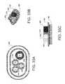
- FIG. 17is a top view of the capacitor of FIG. 1 with a jumper wire connecting selected capacitor sections in series, and also shown connected in an electrical circuit to a compressor motor;
- FIG. 18is a schematic circuit diagram of the capacitor of FIG. 1 connected as shown in FIG. 17 ;
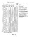
- FIG. 19is a chart showing the single value capacitance values that may be provided by the capacitor of FIG. 1 ;
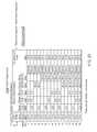
- FIG. 20is a chart showing dual value capacitances that may be provided by the capacitor of FIG. 1 ;
- FIG. 21is another chart showing dual value capacitances that may be provided by the capacitor of FIG. 1 ;
- FIG. 22is another chart showing dual value capacitances that may be provided by the capacitor of FIG. 1 ;
- FIG. 23is another chart showing dual value capacitances that may be provided by the capacitor of FIG. 1 ;
- FIG. 24is a sectional view of the capacitor of FIG. 1 , taken generally along the lines 24 - 24 of FIG. 2 , but showing the capacitor after failure of the capacitive element;
- FIG. 25is a sectional view of a capacitor according to the invention herein;
- FIG. 26is a side elevation view of the capacitive element of the capacitor of FIG. 25 , including conductors connected to the capacitor sections thereof;
- FIG. 27is a folded top and bottom view of the capacitive element of the capacitor of FIG. 26 including conductors connected to capacitor sections thereof;
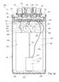
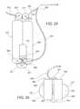
- FIG. 28is a sectional view of a capacitor according to the invention herein;
- FIG. 29is a perspective view of the capacitive element of the capacitor of FIG. 28 , including some of the conductors connected to the capacitor sections thereof;
- FIG. 30is a top view of the capacitive element of the capacitor of FIG. 28 , including conductors connected to capacitor sections thereof.
- FIGS. 31A-Cillustrate perspective views of a capacitor including an elliptically-shaped case
- FIGS. 32A-Cillustrate front and side views of a capacitor including an elliptically-shaped case
- FIGS. 33A-Cillustrate views of a cover assembly for an elliptically-shaped case
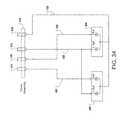
- FIG. 34is a schematic circuit diagram of the capacitor of FIGS. 31A-C .
- FIGS. 35A and 35Billustrate side views of a capacitor including an elliptically-shaped case and mounting brackets.
- a capacitor 10is shown in FIGS. 1-3 , as well as in other Figures to be described below.
- the capacitor 10is adapted to replace any one of a large number of capacitors. Therefore, a serviceman may carry a capacitor 10 on a service call and, upon encountering a failed capacitor, the serviceman can utilize the capacitor 10 to replace the failed capacitor with the capacitor 10 being connected to provide the same capacitance value or values of the failed capacitor.
- the capacitor 10has a capacitive element 12 having a plurality of capacitor sections, each having a capacitance value.
- the capacitive element 12is also shown in FIGS. 4 and 5 .
- the capacitive element 12has six capacitor sections 20 - 25 .
- the capacitive element 12is a wound cylindrical element manufactured by extension of the techniques described in my prior U.S. Pat. No. 3,921,041, my U.S. Pat. No. 4,028,595, my U.S. Pat. No. 4,352,145 and my U.S. Pat. No. 5,313,360, incorporated herein by reference.
- the capacitive element 12has a central spool or mandrel 28 , which has a central opening 29 .
- First and second dielectric films, each having a metalized layer on one side thereof,are wound in cylindrical form on the mandrel 28 with the non-metalized side of one film being in contact with the metalized side of the other. Selected portions of one or both of the metalized layers are removed in order to provide a multiple section capacitive element.
- Element insulation barriersare inserted into the winding to separate the capacitor sections, the element insulation barriers also assuming a cylindrical configuration.
- element insulation barriers 30 - 34are provided to separate the six capacitor sections 20 - 25 , with element insulation barrier 30 separating capacitor sections 20 and 21 , element insulation barrier 31 separating capacitor sections 21 and 22 , element insulation barrier 32 separating capacitor sections 22 and 23 , element insulation barrier 33 separating capacitor sections 23 and 24 , and element insulation barrier 34 separating capacitor sections 24 and 25 .
- the element insulation barriersare insulating polymer sheet material, which in the capacitive element 12 is polypropylene having a thickness of 0.005 inches, wound into the capacitive element 12 . Thickness of 0.0025 to 0.007 may be used. Other materials may also be used.
- the barrierseach have about 23 ⁇ 4-4 wraps of the polypropylene sheet material, wherein the element insulation barriers have a thickness of about 0.013 to 0.020 inches.
- the barriers 30 - 34are thicker than used before in capacitors with fewer capacitor sections. The important characteristic of the barriers 30 - 34 is that they are able to withstand heat from adjacent soldering without losing integrity of electrical insulation, such that adjacent sections can become bridged.
- the metalized filmseach have one unmetalized marginal edge, such that the metalized marginal edge of one film is exposed at one end of the wound capacitive element 12 and the metalized marginal edge of the other film is exposed at the other end of the capacitive element 12 .
- the barriers 30 - 34do not extend from the film, and an element common terminal 36 is established contacting the exposed metalized marginal edges of one metalized film of all the capacitor sections 20 - 25 .
- the element common terminal 36is preferably a zinc spray applied onto the end of the capacitive element 12 .
- the element insulation barriers 30 - 34extend above the wound metalized film.
- An individual capacitor element section terminalis provided for each of the capacitive sections 20 - 25 , also by applying a zinc or other metallic spray onto the end of the capacitive element 12 with the zinc being deployed on each of the capacitor sections 20 - 25 between and adjacent the element insulation barriers 30 - 34 .
- the element section terminalsare identified by numerals 40 - 45 .
- Element section terminal 40 of capacitor section 20extends from the outer-most element insulation barrier 30 to the outer surface of the capacitive element 12
- the element section terminal 45 of capacitor section 25extends from the inner-most element insulation barrier 34 to the central mandrel 28 .
- Element section terminals 41 - 44are respectively deployed on the capacitor sections 21 - 24 .
- Conductors preferably in the form of six insulated wires 50 - 55each have one of their ends respectively soldered to the element section terminals 40 - 45 , as best seen in FIG. 5 .
- the thickness of the polypropylene barriers 30 - 34resists any burn-through as a result of the soldering to connect wires 50 - 55 to the terminals 40 - 45 .
- the insulation of the wires 50 - 55is color coded to facilitate identifying which wire is connected to which capacitor section.
- Wire 50 connected to element section terminal 40 of capacitor section 20has blue insulation
- wire 51 connected to element section terminal 41 of capacitor section 21has yellow insulation
- wire 52 connected to element section terminal 42 of capacitor section 22has red insulation
- wire 53 connected to element section terminal 43 of capacitor section 23has white insulation
- wire 54 connection to element section terminal 44 of capacitor section 24has white insulation
- wire 55 connected to element section terminal 45 of capacitor section 25has green insulation.
- the capacitive element 12is further provided with foil strip conductor 38 , having one end attached to the element common terminal 36 at 37 .
- the foil strip conductor 38is coated with insulation, except for the point of attachment 37 and the distal end 39 thereof.
- the conductor 50 connected to the outer capacitor element section 20 and its terminal 30may also be a foil strip conductor. If desired, foil or wire conductors may be utilized for all connections.
- the capacitor section 20has a value of 25.0 microfarads and the capacitor section 21 has a capacitance of 20.0 microfarads.
- the capacitor section 22has a capacitance of 10.0 microfarads.
- the capacitor section 23has a capacitance of 5.5 microfarads, but is identified as having a capacitance of 5.0 microfarads for purposes further discussed below.
- the capacitor section 24has a capacitance of 4.5 microfarads but is labeled as having a capacitance of 5 microfarads, again for purposes described below.
- the capacitor section 25has a capacitance of 2.8 microfarads.
- the capacitor section 20 with the largest capacitance valuealso has the most metallic film, and is therefore advantageously located as the outer section or at least one of the three outer sections of the capacitive element 12 .
- the capacitor 10also has a case 60 , best seen in FIGS. 1-3 , having a cylindrical side wall 62 , a bottom wall 64 , and an open top 66 of side wall 62 .
- the case 60is formed of aluminum and the cylindrical side wall 62 has an outside diameter of 2.50 inches. This is a very common diameter for capacitors of this type, wherein the capacitor 10 will be readily received in the mounting space and with the mounting hardware provided for the capacitor being replaced. Other diameters may, however, be used, and the case may also be plastic or of other suitable material.
- the capacitive element 12 with the wires 50 - 55 and the foil strip 38are received in the case 60 with the element common terminal 36 adjacent the bottom wall 64 of the case.
- An insulating bottom cup 70is preferably provided for insulating the capacitive element 12 from the bottom wall 64 , the bottom cup 70 having a center post 72 that is received in the center opening 29 of the mandrel 28 , and an up-turned skirt 74 that embraces the lower side wall of the cylindrical capacitive element 12 and spaces it from the side wall 62 of the case 60 .
- An insulating fluid 76is provided within the case 60 , at least partly and preferably substantially surrounding the capacitive element 12 .
- the fluid 76may be the fluid described in my U.S. Pat. No. 6,014,308, incorporated herein by reference, or one of the other insulating fluids used in the trade, such as polybutene.
- the capacitor 10also has a pressure interrupter cover assembly 80 best seen in FIGS. 1-3, 8-10 and 24 .
- the cover assembly 80includes a deformable circular cover 82 having an upstanding cylindrical skirt 84 and a peripheral rim 86 as best seen in FIGS. 9 and 10 .
- the skirt 84fits into the open top 66 cylindrical side wall 62 of case 60
- the peripheral rim 86is crimped to the open top 66 of the case 60 to seal the interior of the capacitor 10 and the fluid 76 contained therein, as shown in FIGS. 1 and 3 .
- the pressure interrupter cover assembly 80includes seven cover terminals mounted on the deformable cover 82 .
- a common cover terminal 88is mounted generally centrally on the cover 82
- section cover terminals 90 - 95are mounted at spaced apart locations surrounding the common cover terminal 88 .
- the section cover terminal 91has three upstanding blades 98 , 100 and 102 mounted on the upper end of a terminal post 104 .
- Terminal post 104has a distal end 105 , opposite the blades 98 , 100 and 102 .
- the cover 82has an opening 106 for accommodating the terminal post 104 , and has a beveled lip 107 surrounding the opening.
- a shaped silicone insulator 108fits snuggly under the cover in the beveled lip 107 and the terminal post 104 passes through the insulator 108 .
- an insulator cup 110also surrounds the post 104 , and the insulator cup 110 sits atop the silicone insulator 108 ; thus, the terminal 91 and its terminal post 104 are well insulated from the cover 82 .
- the other cover section terminals 92 - 95are similarly mounted with an insulator cup and a silicone insulator.
- the common cover terminal 88has four blades 120 , and a terminal post 122 that passes through a silicone insulator 112 .
- the common cover terminal 88mounts cover insulator barrier 114 that includes an elongated cylindrical center barrier cup 116 surrounding and extending above the blades 120 of the common cover terminal 88 , and six barrier fins 118 that extend respectively radially outwardly from the elongated center barrier cup 116 such that they are deployed between adjacent section cover terminals 90 - 95 . This provides additional protection against any arcing or bridging contact between adjacent section cover terminals or with the common cover terminal 88 .
- the common cover terminal 88may be provided with an insulator cup 116 , preferably extending above blades 120 but with no separating barrier fins, although the barrier fins 118 are preferred.
- the terminal post 122extends through an opening in the bottom of the base 117 of the insulating barrier cup 116 , and through the silicone insulator 112 , to a distal end 124 .
- the pressure interrupter cover assembly 80has a fiberboard disc 126 through which the terminal posts 122 , terminal post 104 and the terminal posts of the other section cover terminals extend.
- the disc 126may be also fabricated of other suitable material, such as polymers.
- the terminal posts 104 , 122 , etc.are configured as rivets with rivet flanges 128 for assembly purposes.
- the terminal posts 104 , 122 , etc.are inserted through the disc 126 , insulators 108 , 112 , insulator cups 110 and barrier cup 116 , and the cover terminals 88 , 90 - 95 are spot welded to the ends of the rivets opposite the rivet flanges 128 .
- the rivet flanges 128secure the cover terminals 88 , 90 - 95 in the cover 82 , together with the insulator barrier 114 , insulator cups 110 and silicone insulators 108 , 112 .
- the fiberboard disc 126facilitates this assembly, but may be omitted, if desired.
- the distal ends of the terminal postsare preferably exposed below the rivet flanges 128 .
- the cover assembly 80has a disconnect plate 130 , perhaps best seen in FIGS. 3, 9 and 10 .
- the disconnect plate 130is made of a rigid insulating material, such as a phenolic, is spaced below the cover 82 by a spacer 134 in the form of a skirt.
- the disconnect plate 130is provided with openings accommodating the distal ends of the terminal posts, such as opening 136 accommodating the distal end 105 of terminal post 104 and opening 138 accommodating the distal end 124 of the terminal post 122 .
- the disconnect plate 130may be provided with raised guides, such as linear guides 140 and dimple guides 142 , generally adjacent the openings accommodating the distal ends of terminal posts. These guides are for positioning purposes as discussed below.
- the conductors between the capacitor sections and the terminal postswere generally foil strips, such as the one used for the common element terminal 36 of the capacitive element 12 herein.
- the foil stripswere positioned on a breaker plate over the distal ends of terminal posts, and were welded to the distal ends of the terminal posts.
- the distal end 39 of the foil strip 38is connected to the distal end 124 of terminal post 122 by welding, as in prior capacitors.
- the wires 50 - 55are not well-configured for welding to the distal ends of the terminal posts of the cover section terminals. However, the wires 50 - 55 are desirable in place of foil strips because they are better accommodated in the case 60 and have good insulating properties, resist nicking and are readily available with colored insulations.
- foil tabs 56are welded to each of the distal ends of the terminal posts of the section cover terminals 90 - 95 , and the guides 140 , 142 are helpful in positioning the foil tabs 56 for the welding procedure. The attachment may be accomplished by welding the distal end of a foil strip to the terminal post, and then cutting the foil strip to leave the foil tab 56 .
- the conductor 58 of wire 50is soldered to the tab 56 , by solder 57 .
- the insulation 59 of wire 50has been stripped to expose the conductor 58 .
- the other wires 51 - 55are similarly connected to their respective cover section terminals.
- the foil tabsmay be soldered to the wires and the tabs may then be welded to the terminal posts, if desired, or other conductive attachment may be employed.
- each of the capacitor sections 20 - 25is connected to a corresponding section cover terminal 90 - 95 by a respective one of color coded wires 50 - 55 .
- the insulator cups 110 associated with each of the section cover terminals 90 - 95are also color coded, using the same color scheme as used in the wires 50 - 55 . This facilitates assembly, in that each capacitor section and its wire conductor are readily associated with the correct corresponding section cover terminal, so that the correct capacitor sections can be identified on the cover to make the desired connections for establishing a selected capacitance value.
- the connections of the wires 50 - 55 and the foil 38 to the terminal postsare made prior to placing the capacitive element 12 in the case 60 , adding the insulating fluid 76 , and sealing the cover 82 of cover assembly 80 to the case 60 .
- the case 60may be labeled with the capacitance values of the capacitance sections 20 - 25 adjacent the cover terminals, such as on the side of case 60 near the cover 82 or on the cover 82 .
- the capacitor 10may be used to replace a failed capacitor of any one of over two hundred different capacitance values, including both single and dual applications. Therefore, a serviceman is able to replace virtually any failed capacitor he may encounter as he makes service calls on equipment of various manufacturers, models, ages and the like.
- Air conditioning unitstypically have two capacitors; a capacitor for the compressor motor which may or may not be of relatively high capacitance value and a capacitor of relatively low capacitance value for a fan motor.
- the compressor motor capacitorstypically have capacitances of from 20 to about 60 microfarads.
- the fan motor capacitorstypically have capacitance values from about 2.5 to 12.5 microfarads, and sometimes as high as 15 microfarads, although values at the lower end of the range are most common.
- capacitor 10is connected to replace a compressor motor capacitor and a fan motor capacitor, where the compressor motor capacitor has a value of 25.0 microfarads and the fan motor capacitor has a value of 4.0 microfarads.
- the 25.0 microfarad replacement capacitance for the compressor motoris made by one of the compressor motor leads 160 being connected to one of the blades of the blue section cover terminal 90 of capacitor section 20 , which has a capacitance value of 25.0 microfarads, and the other compressor motor lead 161 being connected to one of the blades 120 of common cover terminal 88 .
- the lead 162 from the fan motoris connected to the white section cover terminal 94 of capacitor section 24
- the second lead 163 from the fan motoris also connected to the common cover terminal 88 .
- the actual capacitance value of the capacitor section 24 that is connected to the section cover terminal 94is 4.5 microfarads
- the instructions and/or labeling for the capacitor 10indicate that the capacitor section 24 as represented at terminal 94 should be used for a 4.0 microfarad replacement.
- Preferred labeling for this purposecan be “5.0 (4.0) microfarads” or similar.
- the 4.5 microfarad capacitance valueis within approximately 10% of the specified 4.0 microfarad value, and that is within acceptable tolerances for proper operation of the fan motor.
- capacitor section 24 and terminal 94may be connected to replace a 5.0 microfarad capacitance value as well, whereby the 4.5 microfarad actual capacitance value of capacitor section 24 gives added flexibility in replacing failed capacitors.
- the 5.5 microfarad capacitor section 23can be used for either 5.0 microfarad or 6.0 microfarad replacement, and the 2.8 microfarad capacitor section 25 can be used for a 3.0 microfarad replacement or for a 2.5 microfarad additive value.
- FIG. 12schematically illustrates the connection of capacitor sections 20 and 24 to the compressor motor and fan motor shown in FIG. 11 .
- FIG. 13illustrates another connection of the capacitor 10 for replacing a 60.0 microfarad compressor motor capacitor and a 7.5 microfarad fan motor capacitor.
- a 60.0 microfarad capacitance value for the compressor motoris achieved by connecting in parallel the section cover terminal 90 (capacitor section 20 at a value of 25.0 microfarads), section cover terminal 91 (capacitor section 21 at a value of 20.0 microfarads), section cover terminal 92 (capacitor section 22 at a value of 10.0 microfarads) and section cover terminal 93 (capacitor section 23 at a nominal value of 5.0 microfarads).
- the foregoing connectionsare made by means of jumpers 164 , 165 and 166 , which may be supplied with the capacitor 10 .
- FIG. 14diagrammatically illustrates the connection of the capacitor 10 shown in FIG. 13 .
- the capacitor sectionscan also be connected in series to utilize capacitor 10 as a single value replacement capacitor.
- Thishas the added advantage of increasing the voltage rating of the capacitor 10 in a series application, i.e. the capacitor 10 can safely operate at higher voltages when its sections are connected in series.
- the operating voltagewill not be increased as it is established by the existing equipment and circuit, and the increased voltage rating derived from a series connection will increase the life of the capacitor 10 because it will be operating well below its maximum rating.
- the capacitor 10is shown with capacitor section 22 (terminal 92 ) having a value of 10.0 microfarads connected in series with capacitor section 25 (terminal 95 ) having a nominal value of 2.5 microfarads to provide a replacement capacitance value of 2.0 microfarads.
- Leads 175 and 176make the connections from the respective section cover terminals 92 and 95 to the motor, and the element common terminal 36 connects the capacitor sections 22 and 25 of capacitive element 12 .
- FIG. 16the connection of capacitor 10 shown in FIG. 15 is illustrated diagrammatically. In both FIGS. 15 and 16 , it will be seen that the common cover terminal 88 is not used in making series connections.
- each of the capacitor sections 20 - 25is rated at 440 volts. However, when two or more capacitor sections 20 - 25 are connected in series, the applied voltage section is divided between the capacitor sections in inverse proportion to their value. Thus, in the series connection of FIGS. 15 and 16 , the nominal 2.5 microfarad section sees about 80% of the applied voltage and the 10.0 microfarad section sees about 20% of the applied voltage. The net effect is that the capacitor 10 provides the 2.0 microfarad replacement value at a higher rating, due to the series connection. In this configuration, the capacitor 10 is lightly stressed and is apt to have an extremely long life.
- the capacitor sections of the capacitor 10are shown connected in a combination of parallel and series connections to provide additional capacitive values at high voltage ratings, in this case 5.0 microfarads.
- the two capacitor sections 23 and 24each having a nominal value of 5.0 microfarads is connected in parallel by jumper 177 between their respective cover section terminals 93 and 94 .
- the leads 178 and 179 from a compressor motorare connected to the section cover terminal 92 of capacitor section 22 having a value of 10.0 microfarads, and the other lead is connected to cover section terminal 94 of capacitor section 24 .
- a capacitance value of 5.0 microfaradsis provided according to the following formula
- the connection of capacitor 10 illustrated in FIG. 17is shown diagrammatically in FIG. 18 .
- FIG. 19is a chart showing single capacitance values that can be provided by the capacitor 10 connected in parallel. The values are derived by connecting individual capacitor sections into a circuit, or by parallel connections of capacitor sections. The chart should be interpreted remembering that the 2.8 microfarad capacitor section can be used as a 2.5 or 3.0 microfarad replacement, and that the two 5.0 microfarad values are actually 4.5 and 5.5 microfarad capacitor sections, also with possibilities for more replacements.
- FIGS. 20-23are charts showing applications of capacitor 10 in replacing both a fan motor capacitor and a compressor motor capacitor. This is an important capability, because many air conditioning systems are equipped with dual value capacitors and when one of the values fails, another dual value capacitor must be substituted into the mounting space bracket.
- the chart of FIG. 20shows dual value capacitances that can be provided by capacitor 10 wherein the nominal 2.5 microfarad capacitor section 25 is used for one of the dual values, usually the fan motor. Fan motors are generally not rigid in their requirements for an exact capacitance value, wherein the capacitor section 25 may also be used for fan motors specifying a 3.0 microfarad capacitor.
- the remaining capacitor sections 20 - 24are available for connection individually or in parallel to the compressor motor, providing capacitance values from 5.0 to 65.0 microfarads in 5.0 microfarad increments.
- the chart of FIG. 21also shows dual value capacitances that can be provided by capacitor 10 .
- one of the dual valuesis 5.0 microfarads that can be provided by either capacitor section 23 having an actual capacitance value of 5.5 microfarads or by capacitor section 24 having an actual capacitance of 4.5 microfarads.
- the capacitor section 24can also be used for a 4.0 microfarad replacement value, and capacitor section 23 could be used for a 6.0 microfarad replacement value.
- the FIG. 21 chartrepresents more dual replacement values than are specifically listed.
- the other capacitor sectionmay be used in various parallel connections to achieve the second of the dual capacitance values.
- the chart of FIG. 22illustrates yet additional dual value capacitances that can be provided by capacitor 10 .
- Capacitor section 25(nominal 2.5 microfarads) is connected in parallel with one of capacitor section 23 (5.5 microfarads) or capacitor section 24 (4.5 microfarads) to provide a 7.5 microfarad capacitance value as one of the dual value capacitances.
- the remaining capacitor sectionsare used individually or in parallel to provide the second of the dual value capacitances.
- FIG. 23 chartillustrates yet additional dual value capacitances that can be provided by capacitor 10 , where capacitor section 22 (10 microfarads) is dedicated to provide one of the dual values. The remaining capacitor sections are used individually or in parallel for the other of the dual values.
- any one or group of capacitor sectionsmay be used for one of a dual value, with a selected one or group of the remaining capacitor sections connected to provide another capacitance value.
- the capacitor 10could provide six individual capacitance values corresponding to the capacitor sections, or three, four or five capacitance values in selected individual and parallel connections. Additional single values can be derived from series connections.
- the six capacitor sections 20 - 25can provide hundreds of replacement values, including single and dual values. It will further be appreciated that if fewer replacement values are required, the capacitor 10 can be made with five or even four capacitor sections, and that if more replacement values were desired, the capacitor 10 could be made with more than six capacitor sections. It is believed that, at least in the intended field of use for replacement of air conditioner capacitors, there should be a minimum of five capacitor sections and preferably six capacitor sections to provide an adequate number of replacement values.
- the pressure interrupter cover assembly 80provides such protection for the capacitor 10 and its capacitive element 12 .
- the capacitor 10is shown after failure. Outgassing has caused the circular cover 82 to deform upwardly into a generally domed shape.
- the terminal posts 104 , 122are also displaced upwardly from the disconnect plate 130 , and the weld connection of the distal end 124 of common cover terminal post 122 to the distal end 39 foil lead 38 from the element common terminal 36 of the capacitive element 12 is broken, and the welds between the foil tabs 56 and the terminal posts 104 of the section cover terminals 90 - 95 are also broken, the separation at section cover terminals 91 and 94 being shown.
- the preferred pressure interrupter cover assemblyincludes the foil lead 38 and foil tabs 56 , frangibly connected to the distal ends of the terminal posts, the frangible connections both known in the art and to be developed may be used.
- the terminal poststhemselves may be frangible.
- the capacitor sections of the capacitor 10are utilized in a series connection, it is necessary that only one of the terminal posts used in the series connection be disconnected from its foil tab at the disconnect plate 130 to remove the capacitive element from an electrical circuit.
- the outgassing conditionwill persist until the pressure interrupter cover assembly 80 deforms sufficiently to cause disconnection from the circuit, and it is believed that an incremental amount of outgassing may occur as required to cause sufficient deformation and breakage of the circuit connection at the terminal post of one of the section cover terminal.
- the common cover terminal 88will be used and the central location of the common cover terminal 88 will cause fast and certain disconnect upon any failure of the capacitive element.
- the common cover terminal 88may be twisted to pre-break the connection of the terminal post 122 with the foil strip 38 , thus eliminating the requirement of any force to break that connection in the event of a failure of the capacitive element 12 .
- the force that would otherwise be required to break the connection of common cover terminal post 122is then applied to the terminal posts of the section cover terminals, whereby the section cover terminals are more readily disconnected. This makes the pressure interrupter cover assembly 80 highly responsive in a series connection configuration.
- the structural aspects of welding foil tabs to the distal ends of the terminal posts corresponding to the various capacitor sections and thereafter soldering the connecting wires onto the foil tabs 56is also believed to make the pressure interrupter cover assembly 80 more responsive to failure of the capacitive element 12 .
- the solder and wiregreatly enhance the rigidity of the foil tabs 56 wherein upon deformation of the cover 82 , the terminal posts break cleanly from the foil tabs 56 instead of pulling the foil tabs partially through the disconnect plate before separating.
- the capacitor 10despite having a common cover terminal and section cover terminals for six capacitor sections, is able to satisfy safety requirements for fluid-filled metalized film capacitors, which is considered a substantial advance in the art.
- FIGS. 26-28Another capacitor 200 according to the invention herein is illustrated in FIGS. 26-28 .
- the capacitor 200has the same or similar external appearance and functionality as capacitor 10 , and is adapted to replace any one of a large number of capacitors with the capacitor 200 connected to provide the same capacitance value or values of a failed capacitor.
- the capacitor 200is characterized by a capacitive element 212 having two wound cylindrical capacitive elements 214 and 216 stacked in axial alignment in case 60 .
- the first wound cylindrical capacitive element 214provides three capacitor sections 20 a , 22 a and 23 a
- the second wound cylindrical element 216provides an additional three capacitive sections 21 a , 24 a and 25 a .
- These capacitor sectionscorrespond in capacitance value to the capacitor sections 20 - 25 of capacitor 10 , i.e. capacitor sections 20 and 20 a have the same capacitance value, capacitor sections 21 and 21 a have the same capacitance value, etc.
- the wound cylindrical capacitive element 214has a central spool or mandrel 228 , which has a central opening 229 .
- First and second dielectric films, each having metalized layer on one side thereof,are wound in cylindrical form on the mandrel 228 with the non-metalized size of one film being in contact with the metalized side of the other. Selected portions of one or both of the metalized layers are removed in order to provide multiple sections in the wound cylindrical capacitive element.
- Element insulation barriers 230 and 231are inserted into the winding to separate the capacitor sections, the element insulation barriers also assuming a cylindrical configuration, with the element insulation barrier 230 separating capacitor sections 20 a and 22 a , and element insulation barrier 231 separating capacitor sections 22 a and 23 a .
- Zinc or other metal sprayis applied between the barriers to form section terminals 40 a , 42 a and 43 a at one end of wound cylindrical capacitive element 214 , and first common element terminal 36 a.
- the second wound cylindrical capacitive element 216is similarly formed, on a mandrel 226 with central opening 227 , providing three capacitor sections 21 a , 24 a and 25 a , with insulation barriers 232 and 233 separating the sections.
- the insulation barriersmay be as described above with respect to capacitive element 12 , i.e. polypropylene barriers sufficient to withstand heat from adjacent soldering without loosing the integrity of electrical insulation.
- the capacitor sections 21 a , 24 a and 25 aare also metal sprayed to form section terminals 41 a , 44 a and 45 a with capacitance values respectively corresponding to sections 41 , 44 and 45 of capacitive element 12 .
- Element common terminal 36 a ′is also formed.
- Element common terminal 36 a of wound cylindrical capacitive element 214connects the sections 20 a , 22 a and 23 a thereof, and an element common terminal 36 a ′ of wound cylindrical capacitive element 216 electrically connects the capacitor sections 21 a , 24 a and 25 a .
- the element common terminals 36 a and 36 a ′are connected by a foil strip 236 , wherein they become the common terminal for all capacitor sections.
- the wound cylindrical capacitive elements 214 and 216are stacked vertically in the case 60 , with the common element terminals 36 a , 36 a ′ adjacent to each other such that any contact between these common element terminals is normal and acceptable because they are connected as the common terminal for all capacitor sections.
- An insulator cup 270is positioned in the bottom of case 60 , to protect element section terminals 21 a , 24 a and 25 a from contact with the case 60 and a post 272 keeps the wound cylindrical elements 214 and 216 aligned and centered in case 60 .
- Conductors 50 a - 55 apreferably in the form of six insulated foil strips or insulated wires, each have one of their respective ends soldered to corresponding element section terminals 20 a - 25 a , and have their other respective ends connected to the corresponding terminal posts of pressure interrupter cover assembly 80 .
- One of the element common terminals 36 a , 36 a ′is connected to the common cover terminal post 122 by conductor 38 a .
- the conductorsare foil strips, all of the conductors may be connected as described above with respect to the foil strip 38 , and if the conductors are insulated wire conductors they may be connected as described above with respect to the insulated wires 50 - 55 .
- the case 60is filled with an insulating fluid 76 .
- the length L of the two wound cylindrical capacitives 214 and 216i.e. the length of the mandrels 226 and 228 on which the metalized dielectric sheet is wound, is selected in part to provide the desired capacitance values.
- the outer capacitor sections having the greater circumferencial dimensioncontain more metalized dielectric film than the capacitor sections more closely adjacent to the mandrels, and therefore provide a larger capacitance value.
- the longer wound cylindrical capacitive element 214provides the 25 microfarad capacitor section 20 a and the 10 microfarad capacitor section 22 a , with the 5.5 microfarad capacitor section 23 a adjacent mandrel 238 .
- the shorter wound cylindrical capacitive element 216provides the 20 microfarad capacitor section 21 a , the 4.5 microfarad capacitor section 24 a and the 2.8 microfarad capacitor section 25 a.
- a capacitive element 212 made up of two wound cylindrical capacitive elements 214 and 216therefore provides the same capacitance values in its various capacitor sections as capacitive element 12 and, when connected to the cover section terminals 90 - 95 , may be connected in the same way as described above with respect to the capacitor 10 and to provide the same replacement capacitance values shown in the charts of FIGS. 19-23 .
- capacitor 300is shown, also having the same or similar exterior appearance as the capacitor 10 and having the same functionality and replacing failed capacitors of varying values.
- the capacitor 300includes case 60 and pressure interrupter cover assembly 80 , and the capacitor 300 is characterized by a capacitive element provided in six separate wound cylindrical capacitive elements 320 - 325 , each wound cylindrical capacitive element providing one capacitor section 20 b - 25 b of the total capacitive element 312 .
- the capacitive elementincludes a first wound cylindrical capacitive element 320 which provides a capacitive section 20 b , preferably having a capacitance value of 25 microfarads.
- the capacitive section 20 bhas a section terminal 40 b which is connected by conductor 50 b to section cover terminal 90 of the cover assembly 80 , and has bottom common terminal 360 .
- Wound cylindrical capacitor element 321provides the capacitor section 21 b having a value of 20 microfarads, having a section terminal 41 b connected to the cover section terminal 91 by a conductor 51 b .
- This sectionalso has a bottom terminal 361 .
- a wound cylindrical capacitive element 322provides the capacitor section 22 b of capacitance value 10 microfarads, with section terminal 42 b connected to the corresponding section cover terminal 92 by conductor 52 c , and has a bottom terminal 362 .
- Wound cylindrical capacitive element 325provides capacitor section 25 b having sectional terminal 45 b connected to the section cover terminal 95 by insulated wire conductor 55 b . It also has a bottom terminal 325 .
- the wound cylindrical capacitive element 325providing only 2.8 microfarads of capacitance value, is quite small compared to the wound cylindrical capacitive elements 320 , 321 and 322 .
- the four wound cylindrical capacitive elements 320 , 321 , 322 and 325are oriented vertically within the case 60 , but provide sufficient head room to accommodate two additional wound cylindrical capacitive elements 323 and 324 , which are placed horizontally under the cover assembly 80 .
- the wound capacitive element 323provides capacitor section 23 b , preferably having a value of 4.5 microfarads
- the wound cylindrical capacitive element 324provides capacitor section 24 b having a value of 5.5 microfarads.
- These capacitor sectionshave, respectively, section terminals 43 b and 44 b connected to cover terminals 93 and 94 by conductors 53 b and 54 b and bottom terminals 323 and 324 .
- All of the bottom terminals 320 - 325are connected together to form common element terminal 36 b , and are connected to the common cover terminal 88 .
- the bottom terminals 320 , 321 , 322 and 325 of the capacitor sections 20 b , 21 b , 22 b and 25 bare connected together by strips soldered or welded thereto, these strips providing both an electrical connection and a mechanical connection holding the assemblies together. Additionally, they may be wrapped with insulating tape.
- An insulated foil strip 38 bconnects the aforesaid bottom terminals to the common cover terminal.
- the bottom terminals 323 and 324 of capacitor sections 23 b and 24 bare also connected together, and are further connected to the common cover terminal by an insulated foil strip 38 b′.
- the wound cylindrical capacitive elements 320 - 325are placed in case 60 with an insulating fluid 76 .
- the capacitor 300may be used in the same way as described above with respect to capacitor 10 , to provide selected replacement values for a large number of different failed capacitors.
- the wound cylindrical capacitive elements 320 - 325occupy less space in the case 60 than the single wound cylindrical capacitive element 12 of capacitor 10 . This is achieved by using thinner dielectric film wherein the capacitance values can be provided in less volume; however, the voltage rating of the wound cylindrical capacitive elements 320 - 325 is correspondingly less because of the thinner dielectric material. Thus, the capacitors made with this technique may have a shorter life, but benefit from a lower cost of manufacture.
- a capacitor 400is presented that includes an elliptical-shaped case 402 (e.g., an oval-shaped case), which is partially shown in the exploded perspective view of FIG. 31A .
- the capacitor 400provides a similar functionality as the capacitor 10 , and is adapted to replace any of the a large number of capacitors with the capacitor 400 being connected to provide a substantially similar (or equivalent) capacitance value or values of one or more failed capacitors.
- the capacitor 400may include one or more of the design aspects, features, materials, etc. employed by the capacitors presented and described with respect to FIGS. 1-30 .
- the capacitor 400includes two wound cylindrical capacitive elements 404 and 406 that are stacked on their respective sides such that the longitudinal axes of the elements are substantially parallel to each other.
- the corresponding portions of each element's sidemay come into contact; although the sides of the elements may be separated by a distance in some arrangements (e.g., through the use a spacing device, a bracket, etc.).
- This positioning of the capacitive elements 404 and 406may depend upon (or even defined in part by) the dimensions of the elliptically-shaped case 402 .
- the geometry of the case 402may constrain the layout of the components.
- one or more dimensions of a similarly elliptically-shaped casemay adjusted (e.g., increased) to allow the capacitive elements to be positioned differently.
- one or both of the capacitive elementsmay be rotated (with respect to their longitudinal axis by 90O) such that each element is vertically oriented (in comparison to the horizontal orientation illustrated in the figure).
- the manner in which the capacitive elements may be stacked amongst themselvesmay also be adjusted. For example, pairs of elements may be stacked end-to-end (a vertical stack) rather than side-by-side as shown in the figure.
- one or more bracketsmay be used to mount the capacitive elements 404 and 406 in place within the case 402 .
- a u-bracketmay be positioned around one or both of the capacitive elements 404 and 406 to affix the capacitive elements 404 and 406 to the case 402 .
- the u-bracketmay have a curved middle portion that has a shape substantially similar to the cylindrical shape of the respective capacitive element 404 or 406 , and two end portions that include clearance holes for allowing fasteners to pass therethrough.
- a first u-bracket 3502is positioned such that a curved middle portion makes contact with the outer curved surface of the upper capacitive element 404 and two end portions make contact with a top surface of the capacitor 400 (e.g., an inside surface of a cover assembly 410 ). Fasteners can be used to hold the first u-bracket 3502 in place such that upwards pressure is applied to the upper capacitive element 404 .
- a second u-bracket 3504is positioned such that the curved middle portion makes contact with the outer curved surface of the lower capacitive element 406 and the two end portions make contact with a bottom surface of the capacitor 400 (e.g., an inside surface of an insulator cup 408 ).
- Fastenerscan be used to hold the second u-bracket 3504 in place such that downwards pressure is applied to the lower capacitive element 406 .
- a single bracket structure including two curved portionscan be used to hold both of the capacitive elements 404 and 406 in place.
- the u-brackets 3502 , 3504are positioned such that the capacitive elements 404 and 406 are fixed to a side surface of the capacitor 400 (e.g., an inside surface of the case 402 ).
- the first u-bracket 3502is positioned such that the end portions make contact with the inside surface of the case 402 , and fasteners can be used to hold the first u-bracket 3502 in place such that sideways pressure is applied to the upper capacitive element 404 .
- the second u-bracket 3504is positioned such that the end portions make contact with the inside surface of the case 402 , and fasteners can be used to hold the second u-bracket 3504 is place such that sideways pressure is applied to the lower capacitive element 406 .
- the u-brackets 3502 , 3504may be made from any material suitable for mounting the capacitive elements 404 , 406 in place within the case 402 .
- the brackets 3502 , 3504include one or more metals such as copper, iron, nickel, titanium, aluminum, or tin, among others.
- the brackets 3502 , 3504may include an alloy that includes a mixture or metals, such as steel, bronze, or brass, among others.
- the brackets 3502 , 3504may include a material that allows the brackets 3502 , 3504 to form-fit around the respective capacitive element 404 , 406 .
- the brackets 3502 , 3504can include a material that adapts to the shape of the corresponding capacitive element 404 , 406 when the bracket 3502 , 3504 is pressed against the capacitive element 404 , 406 .
- the brackets 3502 , 3504can include a foam, polymer, plastic and/or rubber material.
- the brackets 3502 , 3504may be shaped such that the respective capacitive element 404 , 406 tightly fits in the bracket 3502 , 3504 .
- the capacitive elements 404 , 406may “snap” into the corresponding bracket 3502 , 3504 , thereby providing additional mounting strength.
- the brackets 3502 , 3504may include multiple turns that wrap around the corresponding capacitive element 404 , 406 .
- the brackets 3502 , 3504may be in the form of wiring that wraps around the corresponding capacitive element 404 , 406 for a plurality of turns (e.g., 5 turns, 10 turns, 20 turns, 50 turns, etc.).
- the turnsmay provide a spring fit for the capacitive elements 404 , 406 (e.g., the turns may create an inward force around the circumference of the capacitive elements 404 , 406 that help to hold the capacitive elements 404 , 406 in place).
- the turnsmay serve to hold the corresponding capacitive element 404 , 406 in place within the bracket 3502 , 3504 , and the bracket 3502 , 3504 may be fixed to the case 402 such that the capacitive elements 404 , 406 are mounted within the case 402 of the capacitor 400 in a sturdy manner.
- bracketshave been largely described as being u-brackets, other brackets may also be used.
- shape of the bracketmay be such that it allows for the capacitive elements 404 and 406 to have different arrangements than those shown in the figures.
- the bracketmay allow for the capacitive elements 404 and 406 to be arranged at a horizontal offset relative to each other (e.g., in a diagonal arrangement). Such an arrangement may allow for the height of the capacitor 400 to be reduced.
- the capacitor 400provides a functionality that is similar to the capacitor 10 and can be considered as being adaptable to replace any one of a large number of capacitors (with the capacitor 400 ) to provide the same capacitance value or values of a failed capacitor.
- Each of the capacitive elements 404 and 406 of the capacitor 400can be implemented by using one or more production techniques, such as being wound elements like the two wound cylindrical capacitive elements 214 and 216 .
- each of the capacitive elements 404 and 406provide two capacitor sections, however in some arrangements either or both of the capacitive elements may provide more or less capacitive sections.
- Each capacitor sectionhas a capacitance value that may be equivalent or different.
- each of the capacitive elementsmay be used to provide the same pair of capacitance values.
- capacitive element 404may provide a 1.5 microfarads capacitance value and 5.0 microfarads capacitance
- capacitive element 406may similarly provide a 1.5 microfarads capacitance value and 5.0 microfarads capacitance.
- Other capacitance valuesmay be provided either or both of the capacitive elements 404 and 406 (e.g., including values that are greater or less than values mentioned above), thereby providing a range of values.
- the combined capacitance values provided by the capacitive elementsmay range from single digits (e.g., 1 microfarad) to two and three digits (e.g., tens or even hundreds of microfarads).
- each of the capacitive elements 404 and 406has a central spool or mandrel, which has a central opening.
- First and second dielectric films, each having a metalized layer on one side thereof,are wound in cylindrical form on the mandrel with the non-metalized side of one film being in contact with the metalized side of the other. Selected portions of one or both of the metalized layers are removed in order to provide multiple sections in the wound cylindrical capacitive element.
- Element insulation barriers(similar to barriers 230 and 231 shown in FIG. 25 ) may be inserted into the winding to separate the capacitor sections, the element insulation barriers also assuming a cylindrical configuration.
- Zinc or other metal spraymay be applied between the barriers to form section terminals at one end of each of the wound cylindrical capacitive elements 404 and 406 , along with a common element terminal for each capacitive element.
- the insulation barriersmay be produced for a variety of materials such as polypropylene to withstand heat from soldering or other activities without losing the integrity of electrical insulation.
- Capacitor sectionsmay also be metal sprayed to form section terminals.
- capacitive elementsmay be adjusted to occupy more or less space. This may be achieved by using thinner dielectric film wherein the capacitance values can be provided in less volume; however, the voltage rating of the wound cylindrical capacitive elements may be correspondingly less due to the thinner dielectric material. Thus, the capacitors made with this technique may have a shorter life, but benefit from a lower cost of manufacture.
- each capacitive element 404 and 406respectively connects the sections of the corresponding element.
- the element common terminals of the two capacitive elements 404 and 406are connected using one or more conductors (e.g., foil strip(s), wire(s), etc.), wherein they become the common terminal for all capacitor sections.
- an insulator cup 408e.g., similar to the insulator cup 270 shown in FIG. 25 ) is positioned in the bottom of the elliptically-shaped case 402 , to protect the elements such as the lower positioned capacitive element 406 (and potentially other portions of the elements such as section terminals) from contact with the case.
- One or more mechanical mechanismssuch as a bracket, a post, etc. may keep one or both of the wound cylindrical elements 404 and 406 in proper alignment.
- Conductorspreferably in the form of insulated foil strips or insulated wires, each have one of their respective ends soldered to corresponding element section terminals and have their other respective ends connected to the corresponding terminal posts of a cover assembly such as a cover assembly 410 .
- the cover assembly 410can assist in providing the functionality of a pressure interrupter, as described above.
- a common terminal of each elementis connected to a common cover terminal post by one or more conductors.
- the conductorsmay be foil strips, insulated wire conductors, etc., and one or more connection techniques may be employed.
- the case 402may be filled with an insulating fluid (such as insulating fluid 76 ), however in some arrangements, an insulating fluid may not be used.
- Geometry (length, shape, etc.), dimensions (e.g., length, diameter, etc.), etc. of either or both of the two wound cylindrical capacitive elements 404 and 406may be selected in part to provide the desired capacitance values.
- the outer capacitor sectionsgenerally have greater circumferential dimension and contain more metalized dielectric film compared to the capacitor sections more closely adjacent to the mandrels, and therefore provide a larger capacitance value.
- Each capacitive sectionhas a section terminal which is connected by conductor to a corresponding one of the section cover terminals 412 , 414 and 416 of the cover assembly 410 , and has a bottom common terminal.
- Each of the bottom terminals of the capacitive elements 404 , 406are connected together to form a common element terminal, and is connected to the common cover terminal 418 .
- the bottom terminals of the capacitor sectionsmay be connected together by strips soldered, welded, etc., with these strips providing both an electrical connection and a mechanical connection holding the assemblies together. Additionally, they may be wrapped with insulating tape. An insulated foil strip may connect the bottom terminals to the common cover terminal 418 .
- each cover terminal(such as cover terminal 412 ) includes a number of upstanding blades (e.g., two blades) mounted on the upper end of a terminal post.
- the terminal posthas a distal end, opposite the blades.
- the cover assembly 410has an opening for accommodating the terminal post, and the opening may be formed of one or more shapes and include a variety of features such as a beveled lip that surrounds the opening.
- FIGS. 32A-Cperspective views of the capacitor 400 are presented that show both the internal components of the capacitor (e.g., the capacitive elements 404 and 406 ) and portions of the elliptically-shaped case 402 .
- FIG. 32Apresents a front view of the capacitor 400 while FIGS. 32B and 32C present left side and right side views of the capacitor 400 .
- the electrical connections between componentsare also presented.
- a conductor 420is used to connect a portion of capacitive element 404 and a portion of capacitive element 406 to connect capacitors in parallel to provide one capacitance value.
- a connector 422then connects the parallel-connected capacitors to the cover terminal 412 .
- Connectors 424 and 426respectively connect individual capacitor sections of the capacitive elements 404 and 406 to the respective cover terminals 414 and 416 .
- a connector 428connects the respective common terminal of each capacitive element 404 and 406 to the common cover terminal 418 .
- one or more types of techniquesmay be employed for establishing the electrical connections, for example, one or more of the connectors may be electrical wires, metallic film, etc.
- the cover assembly 410may include a disconnect plate 430 that may be produced from a rigid insulating material, such as a phenolic.
- the disconnect plate 430may include openings to accommodate the distal ends of the terminal posts for the cover terminals (e.g., the cover terminals 412 , 414 and 416 , the common cover terminal 418 ).
- the disconnect plate 430may be provided with raised guides, such as linear guides and dimple guides, generally adjacent the openings accommodating the distal ends of terminal posts.
- the cover assembly 410may provide the functionality of a pressure interrupter. For example, if one or more of the capacitive elements 404 , 406 , or a portion of either or both elements were to fail; the elliptically-shaped cover of the cover assembly (or a portion of the cover) may deform upwardly due to outgassing of the failed element or elements. When deformed, the terminal posts are generally displaced upwardly from the disconnect plate 430 , and the connection (e.g., a weld connection) between one or more terminals and the capacitive elements 404 , 406 are broken.
- a pressure interruptere.g., a weld connection
- the cover terminals 412 , 414 and 416are positioned on the cover assembly 410 to form triangular-shaped group.
- the common cover terminal 418is positioned at a location that can be considered slightly separated from the triangular-shaped group of the cover terminals 412 , 414 and 416 .
- Similar to the presented layoutother layouts, patterns, designs etc. may be employed to position the cover terminals and the common cover terminal upon the cover assembly.
- the cover terminals 412 , 414 and 416may be positioned to generally surround the common cover terminal 418 in a manner similarly illustrated in FIG. 1 and FIG. 2 , for example.
- one or more insulator techniques and mechanismsmay be incorporated into the cover assembly 410 .
- the cover assembly 410may include an insulator barrier capable of separating two or more of the cover terminals and/or the common cover terminal.
- the insulator barriermay include an elongated cylindrical center barrier cup capable of surrounding one or more of the terminals (e.g., the common cover terminal 418 , cover terminal 412 , etc.).
- the height of the barrier cup wallmay extend above the height of the surrounded terminal or terminals. Insulation may also be provided by one or more fins that may extend between two or more terminals. For example, similar to the fins presented in FIGS.
- finsmay extend respectively radially outwardly from an elongated center barrier cup such that they are deployed between adjacent terminals (e.g., cover terminals).
- the height of the finsmay extend above the height of the corresponding terminals, however, fins may also be employed that to not fully extend above the height of one or more of the terminals.
- the elliptical shape of the cross section of the capacitor's case and the cover assemblymay both approximately share a common ellipse shape.
- the ellipse shapecan be considered a curve on a plane surrounding two focal points such that a straight line drawn from one of the focal points to any point on the curve and then back to the other focal point has the same length for every point on the curve.
- An ellipse shapecan also be considered as the set of points such that the ratio of the distance of each point on the curve from a given point (called a focus or focal point) to the distance from that same point on the curve to a given line (called the directrix) is a constant, referred to as the eccentricity of the ellipse.
- a circlecan be considered as having an ellipse shape in which both focal points are positioned at the same location.
- the shape of an ellipse(e.g., how ‘elongated’ it is) is represented by its eccentricity which for an ellipse can be represented by any number from 0 (the limiting case of a circle) to arbitrarily close to but less than 1, for example.
- Ellipsescan also be considered a closed type of conic section: a plane curve formed from the intersection of a cone by a plane.
- the capacitive elementsare each produced to include two capacitor sections that correspondingly provide two capacitance values.
- one or both of the capacitive elementsmay be used produced to provide more or less than two capacitive values.
- the capacitive element 404may provide three capacitance values and capacitive element 406 may provide one capacitive value. Rather than providing a total of four capacitive values between the two capacitive elements 404 , 406 , more or less capacitive values may be provided.
- two capacitive elements 404 , 406are employed in this example, more or less capacitive elements may be used to provide capacitive values for a capacitor.
- each of the capacitive elements 404 , 406provide equivalent capacitance values (e.g., 1.5 microfarad and 5.0 microfarad); however in some arrangements the elements may provide only one common value or entirely different capacitance values.
- the capacitance values provided by the capacitive elements 404 and 406may also different in other arrangements. For example, values greater or less than 1.5 microfarads and/or 5.0 microfarads may be provided by the capacitive elements.
- two of the cover terminalsare connected to the capacitive elements (by respective conductors 424 and 426 ) to each provide 5.0 microfarads (by electrically connecting to either cover terminal and the common cover terminal 418 ).
- the third cover terminal 412is connected to both of the 1.5 microfarads capacitance values provided by the capacitive elements 404 , 406 . Connected in parallel, these two capacitance values combine to provide a capacitance value of 3.0 microfarads at the cover terminal 412 .
- the conductor 428also provides a connection to the common cover terminal 418 included in the cover assembly 410 .
- the capacitance valuese.g., 1.5 microfarads and 5.0 microfarads
- capacitance valuesare available from the capacitor 400 .
- additional capacitance valuesmay be provided.
- a capacitance of 3.0 microfaradis provided by the cover terminal 412 (due the two 1.5 microfarad capacitance values connected in parallel).
- cover terminal 414 or 416By connected either cover terminal 414 or 416 to the cover terminal 412 a capacitance value of 6.5 microfarad is provided (from the 1.5 microfarad capacitance value being connected in parallel with one of the 5.0 microfarad capacitance values).
- a capacitance value if 10.0 microfaradmay be provided by connecting cover terminals 414 and 416 to place the two 5.0 microfarad capacitance values in parallel.
- a capacitance value of 13.0 microfaradis provided between the connected terminals (that connect each of the four capacitance values in parallel) and the common cover terminal 418 .
Landscapes
- Engineering & Computer Science (AREA)
- Power Engineering (AREA)
- Microelectronics & Electronic Packaging (AREA)
- Manufacturing & Machinery (AREA)
- Fixed Capacitors And Capacitor Manufacturing Machines (AREA)
Abstract
Description
Therefore,
and the total capacitance of the
microfarads. The capacitance of each of the capacitor sections20-25 is rated at 440 volts. However, when two or more capacitor sections20-25 are connected in series, the applied voltage section is divided between the capacitor sections in inverse proportion to their value. Thus, in the series connection of
where C1is a parallel connection having the value C+C, in this case 5.0+5.0 for a C1of 10.0 microfarads. With that substitution, the total value is
microfarads. The connection of
Claims (19)
Priority Applications (2)
| Application Number | Priority Date | Filing Date | Title |
|---|---|---|---|
| US15/426,858US9859060B1 (en) | 2017-02-07 | 2017-02-07 | Capacitor with multiple elements for multiple replacement applications |
| US15/841,621US10366840B1 (en) | 2017-02-07 | 2017-12-14 | Capacitor with multiple elements for multiple replacement applications |
Applications Claiming Priority (1)
| Application Number | Priority Date | Filing Date | Title |
|---|---|---|---|
| US15/426,858US9859060B1 (en) | 2017-02-07 | 2017-02-07 | Capacitor with multiple elements for multiple replacement applications |
Related Child Applications (1)
| Application Number | Title | Priority Date | Filing Date |
|---|---|---|---|
| US15/841,621ContinuationUS10366840B1 (en) | 2017-02-07 | 2017-12-14 | Capacitor with multiple elements for multiple replacement applications |
Publications (1)
| Publication Number | Publication Date |
|---|---|
| US9859060B1true US9859060B1 (en) | 2018-01-02 |
Family
ID=60788929
Family Applications (2)
| Application Number | Title | Priority Date | Filing Date |
|---|---|---|---|
| US15/426,858ActiveUS9859060B1 (en) | 2017-02-07 | 2017-02-07 | Capacitor with multiple elements for multiple replacement applications |
| US15/841,621ActiveUS10366840B1 (en) | 2017-02-07 | 2017-12-14 | Capacitor with multiple elements for multiple replacement applications |
Family Applications After (1)
| Application Number | Title | Priority Date | Filing Date |
|---|---|---|---|
| US15/841,621ActiveUS10366840B1 (en) | 2017-02-07 | 2017-12-14 | Capacitor with multiple elements for multiple replacement applications |
Country Status (1)
| Country | Link |
|---|---|
| US (2) | US9859060B1 (en) |
Cited By (24)
| Publication number | Priority date | Publication date | Assignee | Title |
|---|---|---|---|---|
| US20170110252A1 (en)* | 2005-04-07 | 2017-04-20 | American Radionic Company, Inc. | Capacitor with multiple elements for multiple replacement applications |
| USD818437S1 (en) | 2005-12-23 | 2018-05-22 | American Radionic Company, Inc. | Capacitor |
| US10056195B2 (en) | 2006-12-29 | 2018-08-21 | American Radionic Company, Inc. | Electrolytic Capacitor |
| US10056194B2 (en) | 2005-04-07 | 2018-08-21 | American Radionic Company, Inc. | Capacitor with multiple elements for multiple replacement applications |
| US10147549B2 (en) | 2013-05-21 | 2018-12-04 | American Radionic Company, Inc. | Power factor correction capacitors |
| US10147550B1 (en) | 2018-04-27 | 2018-12-04 | American Radionic Company, Inc. | Capacitor with multiple elements for multiple replacement applications |
| US10163571B2 (en) | 2009-11-13 | 2018-12-25 | American Radionic Co., Inc. | Hard start kit for multiple replacement applications |
| US10249439B2 (en) | 2005-04-07 | 2019-04-02 | American Radionic Company, Inc. | Capacitor for multiple replacement applications |
| US10366840B1 (en)* | 2017-02-07 | 2019-07-30 | American Radionic Company, Inc. | Capacitor with multiple elements for multiple replacement applications |
| US10497518B1 (en) | 2017-12-13 | 2019-12-03 | American Radionic Company, Inc. | Hard start kit for multiple replacement applications |
| US10586655B1 (en)* | 2018-12-28 | 2020-03-10 | American Radionic Company, Inc. | Capacitor with multiple elements for multiple replacement applications |
| USD906247S1 (en) | 2019-07-11 | 2020-12-29 | American Radionic Company, Inc. | Capacitor |
| US11183337B1 (en)* | 2005-04-07 | 2021-11-23 | Amrad Manufacturing, Llc | Capacitor with multiple elements for multiple replacement applications |
| US11183338B2 (en) | 2005-04-07 | 2021-11-23 | Amrad Manufacturing, Llc | Capacitor with multiple elements for multiple replacement applications |
| US11183336B2 (en) | 2005-04-07 | 2021-11-23 | Amrad Manufacturing, Llc | Capacitor with multiple elements for multiple replacement applications |
| US11195663B2 (en) | 2017-05-12 | 2021-12-07 | Amrad Manufacturing, Llc | Capacitor with multiple elements for multiple replacement applications |
| US11424077B1 (en) | 2017-12-13 | 2022-08-23 | Amrad Manufacturing, Llc | Hard start kit for multiple replacement applications |
| US20220328254A1 (en)* | 2017-05-12 | 2022-10-13 | Amrad Manufacturing, Llc | Capacitor with multiple elements for multiple replacement applications |
| US11575298B2 (en) | 2021-04-30 | 2023-02-07 | Amrad Manufacturing, Llc | Hard start kit for multiple replacement applications |
| US12125645B1 (en) | 2019-06-07 | 2024-10-22 | Amrad Manufacturing, Llc | Capacitor with multiple elements for multiple replacement applications |
| USD1052528S1 (en) | 2019-06-25 | 2024-11-26 | Amrad Manufacturing, Llc | Capacitor |
| USD1054379S1 (en) | 2020-11-24 | 2024-12-17 | Amrad Manufacturing, Llc | Capacitor with relay |
| USD1055860S1 (en) | 2018-12-13 | 2024-12-31 | Amrad Manufacturing, Llc | Magnet for attachment to a capacitor |
| US12437918B2 (en) | 2023-09-22 | 2025-10-07 | Amrad Manufacturing, Llc | Capacitor mount |
Citations (125)
| Publication number | Priority date | Publication date | Assignee | Title |
|---|---|---|---|---|
| US1665499A (en) | 1928-04-10 | System of grouping units | ||
| US1707959A (en) | 1923-10-12 | 1929-04-02 | Dubilier Condenser Corp | Condenser |
| US1943714A (en) | 1930-05-21 | 1934-01-16 | Gen Electric | Combination high and low capacity condenser |
| GB517718A (en) | 1939-06-21 | 1940-02-07 | Sidney George Brown | Improvements in or relating to electric condensers |
| US2202166A (en) | 1937-11-04 | 1940-05-28 | Mallory & Co Inc P R | Condenser mounting |
| US2569925A (en) | 1948-12-30 | 1951-10-02 | Cornell Dubilier Electric | Terminal block for electrolytic capacitors |
| US2896008A (en) | 1953-12-29 | 1959-07-21 | Mc Graw Edison Co | Seal of bushing to casing of electrical apparatus |
| US3015687A (en) | 1959-11-03 | 1962-01-02 | Sprague Electric Co | Electrical component terminal |
| US3302081A (en) | 1965-09-30 | 1967-01-31 | Gen Electric | Capacitor assembly with high resistance shunt |
| US3304473A (en) | 1963-11-12 | 1967-02-14 | Sprague Electric Co | Nonbursting electrical capacitor |
| US3377510A (en) | 1967-11-09 | 1968-04-09 | Gen Electric | Electrical apparatus |
| US3921041A (en) | 1975-02-24 | 1975-11-18 | American Radionic | Dual capacitor |
| US3988650A (en) | 1974-02-08 | 1976-10-26 | Siemens Aktiengesellschaft | Aluminum-electrolytic capacitor having a low impedance and low inductance |
| US4028595A (en) | 1975-12-02 | 1977-06-07 | American Radionic Co., Inc. | Multi-voltage capacitor section |
| FR2343221A1 (en) | 1976-03-01 | 1977-09-30 | Applied Power Inc | DEVICE FOR MEASURING ANGLE RELATIONSHIPS OF VEHICLE WHEELS |
| US4106068A (en) | 1977-01-27 | 1978-08-08 | General Electric Company | Pressure sensitive interrupter |
| US4107758A (en) | 1977-05-16 | 1978-08-15 | Sprague Electric Company | Fused oil filled capacitor |
| US4112424A (en) | 1976-03-12 | 1978-09-05 | Digicourse, Inc. | Alphanumeric display system |
| US4209815A (en) | 1978-04-17 | 1980-06-24 | Jard, Inc. | Capacitor protective circuit |
| US4240126A (en) | 1979-02-16 | 1980-12-16 | Icar Industria Condensatori Applicazioni Elettroelettroniche S.P.A. | Electric capacitor constructed to prevent explosion |
| US4263638A (en) | 1979-06-25 | 1981-04-21 | American Radionic Co., Inc. | Dial wound capacitor and method of making same |
| GB2070861A (en) | 1979-08-03 | 1981-09-09 | Bosch Gmbh Robert | An electrical capacitor |
| US4312027A (en) | 1980-07-21 | 1982-01-19 | American Radionic Co., Inc. | Multiple capacitor winding with electrostatic shielding |
| US4326237A (en) | 1981-01-02 | 1982-04-20 | Sprague Electric Company | Dual AC motor-run capacitors |
| US4352145A (en) | 1980-11-05 | 1982-09-28 | American Radionic Co., Inc. | Multiple element cylindrical metallized film capacitors and method of making the same |
| US4363078A (en) | 1980-04-17 | 1982-12-07 | Sprague Electric Company | Miniature electrolytic capacitor with anchoring terminal |
| US4398782A (en) | 1981-02-26 | 1983-08-16 | Sprague Electric Company | Interrupter for multisection AC capacitors |
| US4408818A (en) | 1981-02-26 | 1983-10-11 | Sprague Electric Company | Capacitor cover-terminal assembly |
| US4447854A (en) | 1982-11-22 | 1984-05-08 | Sprague Electric Company | Oval dual-AC-capacitor package |
| US4486809A (en) | 1981-02-23 | 1984-12-04 | Emhart Industries, Inc. | Anchoring means for a capacitor |
| US4558394A (en) | 1984-04-02 | 1985-12-10 | American Radionic Co., Inc. | Capacitor unit with multiple selectable capacitance values |
| US4586107A (en) | 1984-06-05 | 1986-04-29 | Gen Electric | Dry capacitor circuit interrupter |
| GB2169747A (en) | 1985-01-14 | 1986-07-16 | Ric Limited | Improvements in protective devices for electrical equipment and components, such as capacitors |
| US4631631A (en) | 1985-10-03 | 1986-12-23 | Emhart Industries, Inc. | Capacitor cover and terminal connection |
| US4633367A (en) | 1985-11-27 | 1986-12-30 | North American Philips Corporation | Pressure sensitive fault current interrupter for metallized film capacitors with oil impregnate |
| US4633365A (en) | 1985-03-05 | 1986-12-30 | American Radionic Co., Inc. | Metallized capacitor with protective interrupter device and method of making the same |
| US4633369A (en) | 1985-02-12 | 1986-12-30 | Cooper Industries, Inc. | Power factor correction capacitor |
| US4639828A (en) | 1985-11-27 | 1987-01-27 | North American Philips Corporation | Pressure sensitive fault current interrupter for multiple capacitor device |
| US4698725A (en) | 1986-03-21 | 1987-10-06 | Aerovox Incorporated | Pressure sensitive interrupters for capacitors |
| US4754361A (en) | 1986-01-20 | 1988-06-28 | Ducati Energia, S.P.A. | Resinated capacitive-body capacitor with interspace and explosion-preventing device |
| US4812941A (en) | 1987-08-19 | 1989-03-14 | Magnetec Corporation | Capacitor and method of manufacture |
| US4897760A (en) | 1988-06-29 | 1990-01-30 | Aerovox, Inc. | Capacitor disconnection |
| US5006726A (en) | 1987-03-23 | 1991-04-09 | Murata Manufacturing Co., Ltd. | Pulse generator including coaxial type capacitor |
| US5019934A (en) | 1986-06-04 | 1991-05-28 | Aerovox Incorporated | Capacitor circuit interruption |
| US5138519A (en) | 1991-09-16 | 1992-08-11 | Stockman Robert M | Selectively variable capacitor |
| US5148347A (en) | 1990-05-09 | 1992-09-15 | Aerovox Incorporated | Polymer-encased electrical capacitor with pressure sensitive circuit interrupter |
| US5313360A (en) | 1993-06-28 | 1994-05-17 | American Radionic Co., Inc. | Dual Capacitor |
| US5381301A (en) | 1993-05-11 | 1995-01-10 | Aerovox Incorporated | Leak-tight and rupture proof, ultrasonically-welded, polymer-encased electrical capacitor with pressure sensitive circuit interrupter |
| US5673168A (en) | 1995-12-19 | 1997-09-30 | United Chemi-Con Manufacturing | High ripple current capacitor |
| US5921820A (en) | 1996-09-24 | 1999-07-13 | Bc Components Holdings B.V. | Passive component |
| US5940263A (en) | 1995-03-23 | 1999-08-17 | Jakoubovitch; Albert | Power capacitor bank switching devices |
| US6009348A (en) | 1998-04-03 | 1999-12-28 | Medtronic, Inc. | Implantable medical device having flat electrolytic capacitor with registered electrode layers |
| US6014308A (en) | 1998-10-28 | 2000-01-11 | American Radionic Co., Inc. | Metallized polymer film capacitor having a high viscosity polyurethane oil insulating fluid |
| US6031713A (en) | 1997-06-25 | 2000-02-29 | Matsushita Electric Industrial Co., Ltd. | Aluminum electrolytic capacitor |
| US6084764A (en) | 1998-12-21 | 2000-07-04 | Hamilton Sundstrand Corporation | Capacitor disconnecting assembly |
| US6141205A (en) | 1998-04-03 | 2000-10-31 | Medtronic, Inc. | Implantable medical device having flat electrolytic capacitor with consolidated electrode tabs and corresponding feedthroughs |
| US6147856A (en) | 1999-03-31 | 2000-11-14 | International Business Machine Corporation | Variable capacitor with wobble motor disc selector |
| US6157531A (en) | 1998-04-03 | 2000-12-05 | Medtronic, Inc. | Implantable medical device having flat electrolytic capacitor with liquid electrolyte fill tube |
| US6212058B1 (en) | 1998-04-01 | 2001-04-03 | Vishay Electronic Gmbh | Power capacitor |
| US6222270B1 (en) | 1997-06-24 | 2001-04-24 | Samsung Electronics Co., Ltd. | Integrated circuit bonding pads including closed vias and closed conductive patterns |
| EP1115128A2 (en) | 2000-01-05 | 2001-07-11 | American Radionic Co., Inc. | Fluid-filled capacitor with pressure interrupter means and internal compressible air chamber |
| US6282081B1 (en) | 1999-02-17 | 2001-08-28 | Hitachi Maxell, Ltd. | Electrode for capacitor, method for producing the same and capacitor |
| US6282078B1 (en) | 2000-04-19 | 2001-08-28 | Real Power Cap Company | Capacitor for car stereo with current distributing capability |
| US20010025618A1 (en) | 2000-03-24 | 2001-10-04 | Kelling Gordon L. | Capacitive remote vehicle starter |
| US6310756B1 (en) | 1999-03-02 | 2001-10-30 | Matsushita Electric Industrial Co., Ltd. | Capacitor |
| US6373720B1 (en) | 1998-04-22 | 2002-04-16 | Alcatel | Module with electronic components |
| US6385490B1 (en) | 1999-12-16 | 2002-05-07 | Cardiac Pacemakers, Inc. | Capacitors with recessed rivets allow smaller implantable defibrillators |
| US6404618B1 (en) | 2000-11-06 | 2002-06-11 | Yosemite Investment Co. Inc. | Electrolytic capacitor operable as an A/C capacitor |
| US6490158B1 (en) | 2001-10-04 | 2002-12-03 | Diversitech Corporation | Motor start capacitor assembly |
| US6697249B2 (en) | 2000-11-09 | 2004-02-24 | Foc Frankenburg Oil Company | Supercapacitor and a method of manufacturing such a supercapacitor |
| US6798677B2 (en) | 2000-08-01 | 2004-09-28 | Alstom | Modular power converter |
| US6807048B1 (en) | 2003-05-30 | 2004-10-19 | Medtronic, Inc. | Electrolytic capacitor for use in an implantable medical device |
| US6819545B1 (en) | 2003-03-21 | 2004-11-16 | Parallax Power Components, Llc | High current capacitors |
| US6842328B2 (en) | 2003-05-30 | 2005-01-11 | Joachim Hossick Schott | Capacitor and method for producing a capacitor |
| US6847517B2 (en) | 2002-11-29 | 2005-01-25 | Honda Motor Co., Ltd. | Polarizable electrode for electric double layer capacitor and methods for producing polarizable electrode and capacitor |
| US6888266B2 (en) | 2001-03-08 | 2005-05-03 | Kold Ban International, Ltd. | Vehicle with switched supplemental energy storage system for engine cranking |
| US6922330B2 (en) | 2002-04-18 | 2005-07-26 | Medtronic, Inc. | Implantable medical device having flat electrolytic capacitor fabricated with laser welded anode sheets |
| US6982539B1 (en) | 2004-03-11 | 2006-01-03 | Diversitech Corporation | Motor starting device |
| US6995971B2 (en) | 2003-05-30 | 2006-02-07 | Medtronic, Inc. | Capacitors including interacting separators and surfactants |
| US7031139B1 (en) | 2002-12-05 | 2006-04-18 | Pacesetter, Inc. | Stackable capacitor having opposed contacts for an implantable electronic medical device |
| US7046498B1 (en) | 2004-12-15 | 2006-05-16 | Shou-Hsiung Huang | C-shaped combination capacitor assembly |
| USD522456S1 (en) | 2002-11-29 | 2006-06-06 | Honda Giken Kogyo Kabushiki Kaisha | Capacitor cell |
| US7110240B2 (en) | 2000-03-20 | 2006-09-19 | Medtronic, Inc. | Implantable medical device having flat electrolytic capacitor with differing sized anode and cathode layers |
| US20060227495A1 (en) | 2005-04-07 | 2006-10-12 | Stockman Robert M | Capacitor for multiple replacement applications |
| US20070025051A1 (en) | 2005-04-07 | 2007-02-01 | Stockman Robert M | Capacitor with multiple elements for multiple replacement applications |
| US7251123B2 (en) | 1998-10-02 | 2007-07-31 | Cardiac Pacemakers, Inc. | Smaller electrolytic capacitors for implantable defibrillators |
| US7365959B1 (en) | 2004-08-12 | 2008-04-29 | Charles Barry Ward | Multi value capacitor |
| US20080158780A1 (en) | 2006-12-29 | 2008-07-03 | American Radionic Company, Inc. | Electrolytic Capacitor |
| US7474520B2 (en) | 2005-05-06 | 2009-01-06 | Asahi Glass Company, Limited | Storage device |
| US7492574B2 (en) | 2005-03-14 | 2009-02-17 | Maxwell Technologies, Inc. | Coupling of cell to housing |
| US7511941B1 (en) | 2005-06-08 | 2009-03-31 | Maxwell Technologies, Inc. | Ultrasonic sealed fill hole |
| US7547233B2 (en) | 2003-09-18 | 2009-06-16 | Panasonic Corporation | Capacitor unit |
| US7667954B2 (en) | 2003-05-30 | 2010-02-23 | Medtronic, Inc. | Capacitor |
| US7710713B2 (en) | 2006-09-20 | 2010-05-04 | Greatbatch Ltd. | Flat sealing of anode/separator assembly for use in capacitors |
| US7848079B1 (en) | 2006-01-18 | 2010-12-07 | Musco Corporation | Multi-capacitor assembly |
| US7867290B2 (en) | 2009-01-12 | 2011-01-11 | Medtronic, Inc. | Separator filled with electrolyte |
| US7881043B2 (en) | 2005-12-01 | 2011-02-01 | Panasonic Corporation | Wound electric double-layer capacitor |
| US7911766B2 (en) | 2004-06-11 | 2011-03-22 | Batscap | Supercapacitor cover with integrated center terminal |
| US20110134584A1 (en) | 2009-11-13 | 2011-06-09 | Stockman Richard W | Hard start kit for multiple replacement applications |
| US7987593B1 (en) | 2009-03-02 | 2011-08-02 | Direct Brand Ltd. | Method for generating selective capacitance values |
| US8029290B2 (en) | 2008-03-10 | 2011-10-04 | Regal Beloit Corporation | Methods and apparatus for coupling capacitors |
| US20110317333A1 (en) | 2009-03-03 | 2011-12-29 | Nesscap Co., Ltd. | Electrical energy storage device |
| US8170662B2 (en) | 2006-08-03 | 2012-05-01 | Cardiac Pacemakers, Inc. | Method and apparatus for charging partitioned capacitors |
| US8174817B2 (en) | 2009-06-16 | 2012-05-08 | High Energy Corp. | Sealed and impregnated wound capacitor assemblies |
| US8274778B2 (en) | 2008-01-17 | 2012-09-25 | Toyota Jidosha Kabushiki Kaisha | Capacitor |
| US8310802B2 (en) | 2006-08-28 | 2012-11-13 | Panasonic Corporation | Metallization film capacitor having divided electrode with fuse |
| US8331076B2 (en) | 2010-07-16 | 2012-12-11 | Ut-Battelle, Llc | Clad fiber capacitor and method of making same |
| EP2587503A2 (en) | 2010-06-28 | 2013-05-01 | International Capacitors S. A. | Power capacitor for low voltage, provided with capacitor elements, a capacitor element and a method for producing said capacitor element |
| US8465555B2 (en) | 2004-07-16 | 2013-06-18 | Cardiac Pacemakers, Inc. | Method and apparatus for high voltage aluminum capacitor design |
| US8514547B2 (en) | 2010-11-01 | 2013-08-20 | Avx Corporation | Volumetrically efficient wet electrolytic capacitor |
| US8514548B2 (en) | 2009-07-27 | 2013-08-20 | The Paper Battery Co. | Compliant energy storing structural sheet |
| US8559161B2 (en) | 2009-11-04 | 2013-10-15 | Panasonic Corporation | Metallized film capacitor and case mold type capacitor including same |
| US20140049205A1 (en) | 2012-08-15 | 2014-02-20 | Rbc Manufacturing Corporation | Start capacitor assemblies and methods for operating electric motors |
| US8761875B2 (en) | 2006-08-03 | 2014-06-24 | Cardiac Pacemakers, Inc. | Method and apparatus for selectable energy storage partitioned capacitor |
| US20140201018A1 (en) | 2008-09-29 | 2014-07-17 | Battelle Memorial Institute | Electric power grid control using a market-based resource allocation system |
| US8842411B2 (en) | 2011-02-23 | 2014-09-23 | Pacesetter, Inc. | RF trapezoidal capacitor based EMI feedthru filter assembly |
| US8853318B2 (en) | 2008-06-06 | 2014-10-07 | Allnex Belgium S.A. | Aqueous radiation curable polyurethane compositions |
| US8861184B2 (en) | 2007-08-07 | 2014-10-14 | MAX-PLANCK-Gesellschaft zur Förderung der Wissenschaften e.V. | Method for fabricating a multi-layer capacitor and a multi-layer capacitor |
| US8861178B2 (en) | 2012-05-25 | 2014-10-14 | Kojima Press Industry Co., Ltd. | Film capacitor element, film capacitor, and method of producing the film capacitor element |
| US8871850B2 (en) | 2006-02-01 | 2014-10-28 | Daikin Industries, Ltd. | Highly dielectric film |
| US20140347784A1 (en) | 2013-05-21 | 2014-11-27 | American Radionic Company, Inc. | Power Factor Correction Capacitors |
| US20150022991A1 (en) | 2005-04-07 | 2015-01-22 | American Radionic Company, Inc. | Capacitor with multiple elements for multiple replacement applications |
| USD729164S1 (en) | 2013-09-02 | 2015-05-12 | Foshan City Shunde District Lun Jiao Sheng Ye Electrical Co., Ltd | Capacitor |
| US9105401B2 (en) | 2011-12-02 | 2015-08-11 | Avx Corporation | Wet electrolytic capacitor containing a gelled working electrolyte |
| US9466429B1 (en) | 2014-02-07 | 2016-10-11 | Cornell Dubilier Marketing, Inc. | Configurable multi-capacitor assembly |
Family Cites Families (20)
| Publication number | Priority date | Publication date | Assignee | Title |
|---|---|---|---|---|
| US4420791A (en) | 1981-12-28 | 1983-12-13 | Emhart Industries, Inc. | Dielectric fluid |
| US4459637A (en) | 1983-05-31 | 1984-07-10 | Emhart Industries, Inc. | Dielectric fluid for a capacitor |
| US4609967A (en) | 1985-10-15 | 1986-09-02 | Emhart Industries, Inc. | Dielectric fluid for a capacitor |
| US4621301A (en) | 1985-10-31 | 1986-11-04 | Emhart Industries, Inc. | Dielectric fluid for a capacitor |
| US4642731A (en) | 1986-06-16 | 1987-02-10 | Emhart Industries, Inc. | Dielectric fluid for a capacitor |
| US5817975A (en)* | 1995-09-21 | 1998-10-06 | Magnetek, Inc. | Housing with integral mounting bracket |
| US7780040B2 (en) | 2005-03-14 | 2010-08-24 | Xerox Corporation | Particle dispenser cartridge arranged with dispenser nozzle outer shutter rails |
| US11183338B2 (en) | 2005-04-07 | 2021-11-23 | Amrad Manufacturing, Llc | Capacitor with multiple elements for multiple replacement applications |
| USD818959S1 (en) | 2005-12-23 | 2018-05-29 | American Radionic Company, Inc. | Capacitor |
| US20070279015A1 (en) | 2006-06-05 | 2007-12-06 | Livingston Francis X | Integrated power factor correction capacitance unit |
| WO2009029348A1 (en) | 2007-08-27 | 2009-03-05 | Diversitech Corporation | Multi-value capacitor with safety disconnect mechanism |
| USD621789S1 (en) | 2009-10-27 | 2010-08-17 | Hon Hai Precision Ind. Co., Ltd. | Electrical connector |
| US8432323B2 (en)* | 2010-07-30 | 2013-04-30 | Motorola Solutions, Inc. | Antenna integrated with a portable communication device |
| JP5154676B2 (en) | 2011-06-29 | 2013-02-27 | 双信電機株式会社 | Capacitor |
| KR101973779B1 (en)* | 2012-11-19 | 2019-04-30 | 삼성디스플레이 주식회사 | Method and device of manufacturing flexible display device |
| USD771567S1 (en) | 2014-02-07 | 2016-11-15 | Siemens Aktiengesellschaft | Corona ring |
| US9916934B1 (en) | 2016-04-11 | 2018-03-13 | Cornell Dubilier Electronics, Inc. | Multi-rated capacitor assembly |
| US9911533B2 (en) | 2016-06-28 | 2018-03-06 | Cornell Dubilier Electronics, Inc. | Capacitor with pressure interrupter |
| US9859060B1 (en)* | 2017-02-07 | 2018-01-02 | American Radionic Company, Inc. | Capacitor with multiple elements for multiple replacement applications |
| US10147550B1 (en) | 2018-04-27 | 2018-12-04 | American Radionic Company, Inc. | Capacitor with multiple elements for multiple replacement applications |
- 2017
- 2017-02-07USUS15/426,858patent/US9859060B1/enactiveActive
- 2017-12-14USUS15/841,621patent/US10366840B1/enactiveActive
Patent Citations (170)
| Publication number | Priority date | Publication date | Assignee | Title |
|---|---|---|---|---|
| US1665499A (en) | 1928-04-10 | System of grouping units | ||
| US1707959A (en) | 1923-10-12 | 1929-04-02 | Dubilier Condenser Corp | Condenser |
| US1943714A (en) | 1930-05-21 | 1934-01-16 | Gen Electric | Combination high and low capacity condenser |
| US2202166A (en) | 1937-11-04 | 1940-05-28 | Mallory & Co Inc P R | Condenser mounting |
| GB517718A (en) | 1939-06-21 | 1940-02-07 | Sidney George Brown | Improvements in or relating to electric condensers |
| US2569925A (en) | 1948-12-30 | 1951-10-02 | Cornell Dubilier Electric | Terminal block for electrolytic capacitors |
| US2896008A (en) | 1953-12-29 | 1959-07-21 | Mc Graw Edison Co | Seal of bushing to casing of electrical apparatus |
| US3015687A (en) | 1959-11-03 | 1962-01-02 | Sprague Electric Co | Electrical component terminal |
| US3304473A (en) | 1963-11-12 | 1967-02-14 | Sprague Electric Co | Nonbursting electrical capacitor |
| US3302081A (en) | 1965-09-30 | 1967-01-31 | Gen Electric | Capacitor assembly with high resistance shunt |
| US3377510A (en) | 1967-11-09 | 1968-04-09 | Gen Electric | Electrical apparatus |
| US3988650A (en) | 1974-02-08 | 1976-10-26 | Siemens Aktiengesellschaft | Aluminum-electrolytic capacitor having a low impedance and low inductance |
| US3921041A (en) | 1975-02-24 | 1975-11-18 | American Radionic | Dual capacitor |
| US4028595A (en) | 1975-12-02 | 1977-06-07 | American Radionic Co., Inc. | Multi-voltage capacitor section |
| FR2343221A1 (en) | 1976-03-01 | 1977-09-30 | Applied Power Inc | DEVICE FOR MEASURING ANGLE RELATIONSHIPS OF VEHICLE WHEELS |
| US4095902A (en) | 1976-03-01 | 1978-06-20 | Applied Power Inc. | Automobile wheel alignment device and method |
| US4112424A (en) | 1976-03-12 | 1978-09-05 | Digicourse, Inc. | Alphanumeric display system |
| US4106068A (en) | 1977-01-27 | 1978-08-08 | General Electric Company | Pressure sensitive interrupter |
| US4107758A (en) | 1977-05-16 | 1978-08-15 | Sprague Electric Company | Fused oil filled capacitor |
| US4209815A (en) | 1978-04-17 | 1980-06-24 | Jard, Inc. | Capacitor protective circuit |
| US4240126A (en) | 1979-02-16 | 1980-12-16 | Icar Industria Condensatori Applicazioni Elettroelettroniche S.P.A. | Electric capacitor constructed to prevent explosion |
| US4263638A (en) | 1979-06-25 | 1981-04-21 | American Radionic Co., Inc. | Dial wound capacitor and method of making same |
| GB2070861A (en) | 1979-08-03 | 1981-09-09 | Bosch Gmbh Robert | An electrical capacitor |
| US4363078A (en) | 1980-04-17 | 1982-12-07 | Sprague Electric Company | Miniature electrolytic capacitor with anchoring terminal |
| US4312027A (en) | 1980-07-21 | 1982-01-19 | American Radionic Co., Inc. | Multiple capacitor winding with electrostatic shielding |
| US4352145A (en) | 1980-11-05 | 1982-09-28 | American Radionic Co., Inc. | Multiple element cylindrical metallized film capacitors and method of making the same |
| US4326237A (en) | 1981-01-02 | 1982-04-20 | Sprague Electric Company | Dual AC motor-run capacitors |
| US4486809A (en) | 1981-02-23 | 1984-12-04 | Emhart Industries, Inc. | Anchoring means for a capacitor |
| US4398782A (en) | 1981-02-26 | 1983-08-16 | Sprague Electric Company | Interrupter for multisection AC capacitors |
| US4408818A (en) | 1981-02-26 | 1983-10-11 | Sprague Electric Company | Capacitor cover-terminal assembly |
| US4447854A (en) | 1982-11-22 | 1984-05-08 | Sprague Electric Company | Oval dual-AC-capacitor package |
| US4558394A (en) | 1984-04-02 | 1985-12-10 | American Radionic Co., Inc. | Capacitor unit with multiple selectable capacitance values |
| US4586107A (en) | 1984-06-05 | 1986-04-29 | Gen Electric | Dry capacitor circuit interrupter |
| GB2169747A (en) | 1985-01-14 | 1986-07-16 | Ric Limited | Improvements in protective devices for electrical equipment and components, such as capacitors |
| US4633369A (en) | 1985-02-12 | 1986-12-30 | Cooper Industries, Inc. | Power factor correction capacitor |
| US4633365A (en) | 1985-03-05 | 1986-12-30 | American Radionic Co., Inc. | Metallized capacitor with protective interrupter device and method of making the same |
| US4631631A (en) | 1985-10-03 | 1986-12-23 | Emhart Industries, Inc. | Capacitor cover and terminal connection |
| US4633367A (en) | 1985-11-27 | 1986-12-30 | North American Philips Corporation | Pressure sensitive fault current interrupter for metallized film capacitors with oil impregnate |
| US4639828A (en) | 1985-11-27 | 1987-01-27 | North American Philips Corporation | Pressure sensitive fault current interrupter for multiple capacitor device |
| US4754361A (en) | 1986-01-20 | 1988-06-28 | Ducati Energia, S.P.A. | Resinated capacitive-body capacitor with interspace and explosion-preventing device |
| US4698725A (en) | 1986-03-21 | 1987-10-06 | Aerovox Incorporated | Pressure sensitive interrupters for capacitors |
| US5019934A (en) | 1986-06-04 | 1991-05-28 | Aerovox Incorporated | Capacitor circuit interruption |
| US5006726A (en) | 1987-03-23 | 1991-04-09 | Murata Manufacturing Co., Ltd. | Pulse generator including coaxial type capacitor |
| US4812941A (en) | 1987-08-19 | 1989-03-14 | Magnetec Corporation | Capacitor and method of manufacture |
| US4897760A (en) | 1988-06-29 | 1990-01-30 | Aerovox, Inc. | Capacitor disconnection |
| US5148347A (en) | 1990-05-09 | 1992-09-15 | Aerovox Incorporated | Polymer-encased electrical capacitor with pressure sensitive circuit interrupter |
| US5138519A (en) | 1991-09-16 | 1992-08-11 | Stockman Robert M | Selectively variable capacitor |
| US5381301A (en) | 1993-05-11 | 1995-01-10 | Aerovox Incorporated | Leak-tight and rupture proof, ultrasonically-welded, polymer-encased electrical capacitor with pressure sensitive circuit interrupter |
| US5313360A (en) | 1993-06-28 | 1994-05-17 | American Radionic Co., Inc. | Dual Capacitor |
| US5940263A (en) | 1995-03-23 | 1999-08-17 | Jakoubovitch; Albert | Power capacitor bank switching devices |
| US5673168A (en) | 1995-12-19 | 1997-09-30 | United Chemi-Con Manufacturing | High ripple current capacitor |
| US5921820A (en) | 1996-09-24 | 1999-07-13 | Bc Components Holdings B.V. | Passive component |
| US6222270B1 (en) | 1997-06-24 | 2001-04-24 | Samsung Electronics Co., Ltd. | Integrated circuit bonding pads including closed vias and closed conductive patterns |
| US6031713A (en) | 1997-06-25 | 2000-02-29 | Matsushita Electric Industrial Co., Ltd. | Aluminum electrolytic capacitor |
| US6212058B1 (en) | 1998-04-01 | 2001-04-03 | Vishay Electronic Gmbh | Power capacitor |
| US6157531A (en) | 1998-04-03 | 2000-12-05 | Medtronic, Inc. | Implantable medical device having flat electrolytic capacitor with liquid electrolyte fill tube |
| US6009348A (en) | 1998-04-03 | 1999-12-28 | Medtronic, Inc. | Implantable medical device having flat electrolytic capacitor with registered electrode layers |
| US6141205A (en) | 1998-04-03 | 2000-10-31 | Medtronic, Inc. | Implantable medical device having flat electrolytic capacitor with consolidated electrode tabs and corresponding feedthroughs |
| US6373720B1 (en) | 1998-04-22 | 2002-04-16 | Alcatel | Module with electronic components |
| US7251123B2 (en) | 1998-10-02 | 2007-07-31 | Cardiac Pacemakers, Inc. | Smaller electrolytic capacitors for implantable defibrillators |
| CA2285721A1 (en) | 1998-10-28 | 2000-04-28 | Robert M. Stockman | Metallized polymer film capacitor having a high viscosity polyurethane oil insulating fluid |
| US6014308A (en) | 1998-10-28 | 2000-01-11 | American Radionic Co., Inc. | Metallized polymer film capacitor having a high viscosity polyurethane oil insulating fluid |
| US6084764A (en) | 1998-12-21 | 2000-07-04 | Hamilton Sundstrand Corporation | Capacitor disconnecting assembly |
| US6282081B1 (en) | 1999-02-17 | 2001-08-28 | Hitachi Maxell, Ltd. | Electrode for capacitor, method for producing the same and capacitor |
| US6310756B1 (en) | 1999-03-02 | 2001-10-30 | Matsushita Electric Industrial Co., Ltd. | Capacitor |
| US6147856A (en) | 1999-03-31 | 2000-11-14 | International Business Machine Corporation | Variable capacitor with wobble motor disc selector |
| US6385490B1 (en) | 1999-12-16 | 2002-05-07 | Cardiac Pacemakers, Inc. | Capacitors with recessed rivets allow smaller implantable defibrillators |
| EP1115128A2 (en) | 2000-01-05 | 2001-07-11 | American Radionic Co., Inc. | Fluid-filled capacitor with pressure interrupter means and internal compressible air chamber |
| US6313978B1 (en) | 2000-01-05 | 2001-11-06 | American Radionic Co., Inc. | Fluid-filled capacitor with pressure interrupter means and internal compressible air chamber |
| US7110240B2 (en) | 2000-03-20 | 2006-09-19 | Medtronic, Inc. | Implantable medical device having flat electrolytic capacitor with differing sized anode and cathode layers |
| US20010025618A1 (en) | 2000-03-24 | 2001-10-04 | Kelling Gordon L. | Capacitive remote vehicle starter |
| US6282078B1 (en) | 2000-04-19 | 2001-08-28 | Real Power Cap Company | Capacitor for car stereo with current distributing capability |
| US6798677B2 (en) | 2000-08-01 | 2004-09-28 | Alstom | Modular power converter |
| US6404618B1 (en) | 2000-11-06 | 2002-06-11 | Yosemite Investment Co. Inc. | Electrolytic capacitor operable as an A/C capacitor |
| US6697249B2 (en) | 2000-11-09 | 2004-02-24 | Foc Frankenburg Oil Company | Supercapacitor and a method of manufacturing such a supercapacitor |
| US6888266B2 (en) | 2001-03-08 | 2005-05-03 | Kold Ban International, Ltd. | Vehicle with switched supplemental energy storage system for engine cranking |
| US6490158B1 (en) | 2001-10-04 | 2002-12-03 | Diversitech Corporation | Motor start capacitor assembly |
| US6922330B2 (en) | 2002-04-18 | 2005-07-26 | Medtronic, Inc. | Implantable medical device having flat electrolytic capacitor fabricated with laser welded anode sheets |
| USD522456S1 (en) | 2002-11-29 | 2006-06-06 | Honda Giken Kogyo Kabushiki Kaisha | Capacitor cell |
| US6847517B2 (en) | 2002-11-29 | 2005-01-25 | Honda Motor Co., Ltd. | Polarizable electrode for electric double layer capacitor and methods for producing polarizable electrode and capacitor |
| US7031139B1 (en) | 2002-12-05 | 2006-04-18 | Pacesetter, Inc. | Stackable capacitor having opposed contacts for an implantable electronic medical device |
| US6930874B2 (en) | 2003-03-21 | 2005-08-16 | Parallax Power Components, Llc | High current capacitors |
| US6819545B1 (en) | 2003-03-21 | 2004-11-16 | Parallax Power Components, Llc | High current capacitors |
| US6807048B1 (en) | 2003-05-30 | 2004-10-19 | Medtronic, Inc. | Electrolytic capacitor for use in an implantable medical device |
| US6995971B2 (en) | 2003-05-30 | 2006-02-07 | Medtronic, Inc. | Capacitors including interacting separators and surfactants |
| US6842328B2 (en) | 2003-05-30 | 2005-01-11 | Joachim Hossick Schott | Capacitor and method for producing a capacitor |
| US7667954B2 (en) | 2003-05-30 | 2010-02-23 | Medtronic, Inc. | Capacitor |
| US7547233B2 (en) | 2003-09-18 | 2009-06-16 | Panasonic Corporation | Capacitor unit |
| US6982539B1 (en) | 2004-03-11 | 2006-01-03 | Diversitech Corporation | Motor starting device |
| US7911766B2 (en) | 2004-06-11 | 2011-03-22 | Batscap | Supercapacitor cover with integrated center terminal |
| US8465555B2 (en) | 2004-07-16 | 2013-06-18 | Cardiac Pacemakers, Inc. | Method and apparatus for high voltage aluminum capacitor design |
| US7365959B1 (en) | 2004-08-12 | 2008-04-29 | Charles Barry Ward | Multi value capacitor |
| US7046498B1 (en) | 2004-12-15 | 2006-05-16 | Shou-Hsiung Huang | C-shaped combination capacitor assembly |
| US7492574B2 (en) | 2005-03-14 | 2009-02-17 | Maxwell Technologies, Inc. | Coupling of cell to housing |
| US20150016012A1 (en) | 2005-04-07 | 2015-01-15 | American Radionic Company, Inc. | Capacitor with multiple elements for multiple replacement applications |
| US20110157764A1 (en) | 2005-04-07 | 2011-06-30 | American Radionic Company, Inc. | Capacitor with multiple elements for multiple replacement applications |
| US7474519B2 (en) | 2005-04-07 | 2009-01-06 | American Radionic Company, Inc. | Capacitor for multiple replacement applications |
| US7423861B2 (en) | 2005-04-07 | 2008-09-09 | American Radionic Company, Inc. | Capacitor with multiple elements for multiple replacement applications |
| US20090052109A1 (en) | 2005-04-07 | 2009-02-26 | American Radionic Company, Inc. | Capacitor for Multiple Replacement Applications |
| US20130343029A1 (en) | 2005-04-07 | 2013-12-26 | American Radionic Company, Inc. | Capacitor with multiple elements for multiple replacement applications |
| US20170236646A1 (en) | 2005-04-07 | 2017-08-17 | American Radionic Company, Inc. | Capacitor for multiple replacement applications |
| US20090219665A1 (en) | 2005-04-07 | 2009-09-03 | American Radionic Company, Inc. | Capacitor with multiple elements for multiple replacement applications |
| US20070236860A1 (en) | 2005-04-07 | 2007-10-11 | American Radionic Company, Inc. | Capacitor for multiple replacement applications |
| US20070025051A1 (en) | 2005-04-07 | 2007-02-01 | Stockman Robert M | Capacitor with multiple elements for multiple replacement applications |
| US7835133B2 (en) | 2005-04-07 | 2010-11-16 | American Radionic Company, Inc. | Capacitor for multiple replacement applications |
| US8891224B2 (en) | 2005-04-07 | 2014-11-18 | America Radionic Company, Inc. | Capacitor with multiple elements for multiple replacement applications |
| US20170110252A1 (en) | 2005-04-07 | 2017-04-20 | American Radionic Company, Inc. | Capacitor with multiple elements for multiple replacement applications |
| US20130003252A1 (en) | 2005-04-07 | 2013-01-03 | American Radionic Company, Inc. | Capacitor for multiple replacement applications |
| US20110063775A1 (en) | 2005-04-07 | 2011-03-17 | American Radionic Company, Inc. | Capacitor for multiple replacement applications |
| US7911762B2 (en) | 2005-04-07 | 2011-03-22 | American Radionic Company, Inc. | Capacitor with multiple elements for multiple replacement applications |
| US7203053B2 (en) | 2005-04-07 | 2007-04-10 | American Radionic Company, Inc. | Capacitor for multiple replacement applications |
| US20170032898A1 (en) | 2005-04-07 | 2017-02-02 | American Radionic Company, Inc. | Capacitor with multiple elements for multiple replacement applications |
| US9536670B2 (en) | 2005-04-07 | 2017-01-03 | American Radionic Company, Inc. | Capacitor with multiple elements for multiple replacement applications |
| US8531815B2 (en) | 2005-04-07 | 2013-09-10 | American Radionic Company, Inc. | Capacitor with multiple elements for multiple replacement applications |
| US20160233030A1 (en) | 2005-04-07 | 2016-08-11 | American Radionic Company, Inc. | Capacitor for Multiple Replacement Applications |
| US9412521B2 (en)* | 2005-04-07 | 2016-08-09 | American Radionic Company, Inc. | Capacitor with multiple elements for multiple replacement applications |
| US9378893B2 (en) | 2005-04-07 | 2016-06-28 | American Radionic Company, Inc. | Capacitor with multiple elements for multiple replacement applications |
| US9343238B2 (en) | 2005-04-07 | 2016-05-17 | American Radionic Company, Inc. | Capacitor for multiple replacement applications |
| US20060227495A1 (en) | 2005-04-07 | 2006-10-12 | Stockman Robert M | Capacitor for multiple replacement applications |
| US20150138690A1 (en) | 2005-04-07 | 2015-05-21 | American Radionic Company, Inc. | Capacitor with multiple elements for multiple replacement applications |
| US8270143B2 (en) | 2005-04-07 | 2012-09-18 | American Radionic Company, Inc. | Capacitor for multiple replacement applications |
| US20150022991A1 (en) | 2005-04-07 | 2015-01-22 | American Radionic Company, Inc. | Capacitor with multiple elements for multiple replacement applications |
| US7474520B2 (en) | 2005-05-06 | 2009-01-06 | Asahi Glass Company, Limited | Storage device |
| US7511941B1 (en) | 2005-06-08 | 2009-03-31 | Maxwell Technologies, Inc. | Ultrasonic sealed fill hole |
| US7881043B2 (en) | 2005-12-01 | 2011-02-01 | Panasonic Corporation | Wound electric double-layer capacitor |
| US7848079B1 (en) | 2006-01-18 | 2010-12-07 | Musco Corporation | Multi-capacitor assembly |
| US8871850B2 (en) | 2006-02-01 | 2014-10-28 | Daikin Industries, Ltd. | Highly dielectric film |
| US8170662B2 (en) | 2006-08-03 | 2012-05-01 | Cardiac Pacemakers, Inc. | Method and apparatus for charging partitioned capacitors |
| US8761875B2 (en) | 2006-08-03 | 2014-06-24 | Cardiac Pacemakers, Inc. | Method and apparatus for selectable energy storage partitioned capacitor |
| US8310802B2 (en) | 2006-08-28 | 2012-11-13 | Panasonic Corporation | Metallization film capacitor having divided electrode with fuse |
| US7710713B2 (en) | 2006-09-20 | 2010-05-04 | Greatbatch Ltd. | Flat sealing of anode/separator assembly for use in capacitors |
| US8537522B2 (en) | 2006-12-29 | 2013-09-17 | American Radionic Company, Inc. | Electrolytic capacitor |
| US20080158780A1 (en) | 2006-12-29 | 2008-07-03 | American Radionic Company, Inc. | Electrolytic Capacitor |
| US20130329342A1 (en) | 2006-12-29 | 2013-12-12 | American Radionic Company, Inc. | Electrolytic Capacitor |
| US20170186554A1 (en) | 2006-12-29 | 2017-06-29 | American Radionic Company, Inc. | Electrolytic Capacitor |
| US7952854B2 (en) | 2006-12-29 | 2011-05-31 | American Radionic Company, Inc. | Electrolytic capacitor |
| US9424995B2 (en) | 2006-12-29 | 2016-08-23 | American Radionic Company, Inc. | Electrolytic capacitor |
| US20110228446A1 (en) | 2006-12-29 | 2011-09-22 | American Radionic Company, Inc. | Electrolytic Capacitor |
| US8861184B2 (en) | 2007-08-07 | 2014-10-14 | MAX-PLANCK-Gesellschaft zur Förderung der Wissenschaften e.V. | Method for fabricating a multi-layer capacitor and a multi-layer capacitor |
| US8274778B2 (en) | 2008-01-17 | 2012-09-25 | Toyota Jidosha Kabushiki Kaisha | Capacitor |
| US8029290B2 (en) | 2008-03-10 | 2011-10-04 | Regal Beloit Corporation | Methods and apparatus for coupling capacitors |
| US8853318B2 (en) | 2008-06-06 | 2014-10-07 | Allnex Belgium S.A. | Aqueous radiation curable polyurethane compositions |
| US20140201018A1 (en) | 2008-09-29 | 2014-07-17 | Battelle Memorial Institute | Electric power grid control using a market-based resource allocation system |
| US7867290B2 (en) | 2009-01-12 | 2011-01-11 | Medtronic, Inc. | Separator filled with electrolyte |
| US7987593B1 (en) | 2009-03-02 | 2011-08-02 | Direct Brand Ltd. | Method for generating selective capacitance values |
| US20110317333A1 (en) | 2009-03-03 | 2011-12-29 | Nesscap Co., Ltd. | Electrical energy storage device |
| US8174817B2 (en) | 2009-06-16 | 2012-05-08 | High Energy Corp. | Sealed and impregnated wound capacitor assemblies |
| US8514548B2 (en) | 2009-07-27 | 2013-08-20 | The Paper Battery Co. | Compliant energy storing structural sheet |
| US8559161B2 (en) | 2009-11-04 | 2013-10-15 | Panasonic Corporation | Metallized film capacitor and case mold type capacitor including same |
| US20140285949A1 (en) | 2009-11-13 | 2014-09-25 | American Radionic Company, Inc. | Hard Start Kit for Multiple Replacement Applications |
| US20160203916A1 (en) | 2009-11-13 | 2016-07-14 | American Radionic Company, Inc. | Hard Start Kit for Multiple Replacement Applications |
| US20130214720A1 (en) | 2009-11-13 | 2013-08-22 | American Radionic Company, Inc. | Hard Start Kit for Multiple Replacement Applications |
| US8456795B2 (en) | 2009-11-13 | 2013-06-04 | American Radionic Company, Inc. | Hard start kit for multiple replacement applications |
| US8885318B2 (en) | 2009-11-13 | 2014-11-11 | American Radionic Company, Inc. | Hard start kit for multiple replacement applications |
| US20110134584A1 (en) | 2009-11-13 | 2011-06-09 | Stockman Richard W | Hard start kit for multiple replacement applications |
| US9324501B2 (en) | 2009-11-13 | 2016-04-26 | American Radionic Company, Inc. | Hard start kit for multiple replacement applications |
| EP2587503A2 (en) | 2010-06-28 | 2013-05-01 | International Capacitors S. A. | Power capacitor for low voltage, provided with capacitor elements, a capacitor element and a method for producing said capacitor element |
| US8331076B2 (en) | 2010-07-16 | 2012-12-11 | Ut-Battelle, Llc | Clad fiber capacitor and method of making same |
| US8514547B2 (en) | 2010-11-01 | 2013-08-20 | Avx Corporation | Volumetrically efficient wet electrolytic capacitor |
| US8842411B2 (en) | 2011-02-23 | 2014-09-23 | Pacesetter, Inc. | RF trapezoidal capacitor based EMI feedthru filter assembly |
| US9105401B2 (en) | 2011-12-02 | 2015-08-11 | Avx Corporation | Wet electrolytic capacitor containing a gelled working electrolyte |
| US8861178B2 (en) | 2012-05-25 | 2014-10-14 | Kojima Press Industry Co., Ltd. | Film capacitor element, film capacitor, and method of producing the film capacitor element |
| US20140049205A1 (en) | 2012-08-15 | 2014-02-20 | Rbc Manufacturing Corporation | Start capacitor assemblies and methods for operating electric motors |
| US9496086B2 (en) | 2013-05-21 | 2016-11-15 | American Radionic Company, Inc. | Power factor correction capacitors |
| US9318261B2 (en) | 2013-05-21 | 2016-04-19 | American Radionic Company, Inc. | Power factor correction capacitors |
| US20170011855A1 (en) | 2013-05-21 | 2017-01-12 | American Radionic Company, Inc. | Power Factor Correction Capacitors |
| US20150255218A1 (en) | 2013-05-21 | 2015-09-10 | American Radionic Company, Inc. | Power Factor Correction Capacitors |
| US20140347784A1 (en) | 2013-05-21 | 2014-11-27 | American Radionic Company, Inc. | Power Factor Correction Capacitors |
| USD729164S1 (en) | 2013-09-02 | 2015-05-12 | Foshan City Shunde District Lun Jiao Sheng Ye Electrical Co., Ltd | Capacitor |
| US9466429B1 (en) | 2014-02-07 | 2016-10-11 | Cornell Dubilier Marketing, Inc. | Configurable multi-capacitor assembly |
Non-Patent Citations (62)
| Title |
|---|
| "AC Capacitors," brochure by AmRad Engineering, Inc., undated (4 pages). |
| "American Radionic Co., Inc. Introduces . . . The World's First Multiple Metallized Film Dielectric Capacitor Produced from a Single Winding! The Patented Ultramet™ Capacitor," poster by American Radionic Co., Inc. (undated) (one page). |
| "American Radionic Co., Inc. Introduces a New Circuit Component the Patented Ultramet™ Capacitor," poster by American Radionic Co., Inc., (poster undated, 1980 year date appears below one image), (one page). |
| "American Radionic Co., Inc. Introduces a New Circuit Component, The Patented Ultramet™ Capacitor," poster by American Radionic Co., Inc., which is reprint from Electronic News dated Feb. 11, 1980, (one page). |
| "American Radionic Company's Chronology of Patents, New Products and Technology Transfer Programs—From the Present, to the Past, a Thirty-Five Year Review," online website having URL: http:/www.americanradionic.com/content/blogcategory/13/29/8/16 , accessed May 19, 2014 (undated) (3 pages). |
| "American Radionic Introduces Capacitors Without Compromise", color brochure, 1989, (1 page). |
| "American Radionics—Home of the Turbo200 MultiUse Capacitor," online archive of website captured at http://web.archive.org/web/20050309191805fw—/http://www.americanradionic.com/home , Mar. 9, 2005, (16 pages) (accessed May 29, 2014). |
| "AmRad Engineering: Universal Capacitor," The Air Conditioning|Heating|Refrigeration News, Jan. 29, 2005, Printout of website having URL: http://www.archrnews.com/articles/print/amrad-engineering-universal-capacitor (accessed Jun. 2, 2014) (1 page). |
| "Capacitors—Motor Run, Oil Filled Capacitors, AC Rated. AmRad." Online archive of website captured at http://webarchive.org/web/20041214091042/http://americanradionic.com, Dec. 14, 2004, (13 pages) (accessed May 29, 2014). |
| "Capacitors—Motor Run, Oil Filled Capacitors, AC Rated. AmRad." Online archive of website captured at http:/webarchive.org/web/20011126195819/http://www.americanradionic.com, Nov. 26, 2001, (13 pages) (accessed May 29, 2014). |
| "Capacitors—Motor Run, Oil Filled Capacitors, AC Rated. AmRad." Printout of website having URL: http://amradcapacitors.com/index.htm, Jan. 3, 2003(20 pages). |
| "Industrial Power Factor Correction Capacitors," Cornell Dubilier, Undated (1 page). |
| "Product of the Year Awards," Electronic Products Magazine, Jan. 1981, pp. 39-45. |
| "Super-Sized Show," ASHRae Journal Show Daily, 2005 International Air-Conditioning, Heating, Refrigerating Exposition, Tuesday, Feb. 8, 2005 (24 pages). |
| "The Patented Ultramet™ Capacitor," poster by American Radionic Co., Inc., (undated) (three pages). |
| "The Patented Ultramet™ Capacitor. A product of years of American Radionic research & development," poster by American Radionic Co., Inc. (undated) (one page). |
| Answer and affirmative defenses to Complaint by Cornell-Dubliner Electronics, Inc. (Allaman, Melissa) (Entered: Jan. 9, 2015). |
| Answer and affirmative defenses to Complaint by Packard Inc. (Allaman, Melissa) (Entered: Jan. 9, 2015). |
| Case Management and Scheduling Order: Amended Pleadings and Joinder of Parties due by Apr. 9, 2015. Discovery due by Feb. 16, 2016. Dispositive motions due by Apr. 7, 2016. Pretrial statement due by Aug. 11, 2016. All other motions due by Jul. 28, 2016. Plaintiff disclosure of expert report due by Dec. 10, 2015. Defendant disclosure of expert report due by Jan. 14, 2016. Final Pretrial Conference set for Aug. 18, 2016 at 01:15 PM in Orlando Courtroom 4 a before Judge Roy B. Dalton, Jr., Jury Trial Set for the trial team commencing Sep. 6, 2016 at 09:00 AM in Orlando Courtroom 4 a before Judge Roy B. Dalton Jr., Conduct mediation hearing by Mar. 29, 2016. Lead counsel to coordinate dates. Signed by Judge Roy B. Dalton, Jr. on Feb. 10, 2015. (VMF). (Entered: Feb. 10, 2015). |
| Complaint for Patent Infringement against Cornell-Dubliner Electronics, Inc., Packard Inc. with Jury Demand (Filing fee $400 receipt No. ORL-38930) filed by American Radionic Company, Inc. (Attachments: #1 Civil Cover sheet, #2 Exhibit A)(LMM) Modified on Nov. 19, 2014 (LMM). (Entered: Nov. 19, 2014). |
| Declaration of Noah C. Graubart in Support of Plaintiff's Claim Construction Brief by American Radionic Company, Inc. (Attachments: #1 Exhibit 1, #2 Exhibit 2, #3 Exhibit 3, #4 Exhibit 4, #5 Exhibit 5, #6 Exhibit 6) (Graubart, Noah) (Entered: Jun. 18, 2015). |
| Defendants' First Supplemental Disclosure of Non-Infringement and Invalidity Contentions American Radionic, Inc., v. Packard, Inc., and Cornell-Dubilier Electronics, Inc., No. 6:14-cv-01881-RBD-KRS. |
| Document from Defendants' First Supplemental Disclosure of Non-Infringement and Invalidity Contentions that purported to be Standard for Safety UL 810 Capacitors, Underwriters Laboratories Inc. having multiple dates ranging from 1976 to 1988 (22 pages). |
| First Amended Answer and affirmative defenses to 1 Complaint by Cornell-Dubliner Electronics, Inc. (Allaman, Melissa) (Entered: Feb. 4, 2015). |
| First Amended Answer and affirmative defenses to 1 Complaint by Packard Inc. (Allaman, Melissa) (Entered: Jan. 9, 2015). |
| Grainger, "Round Motor Dual Run Capacitor, 40/5 Microfarad Rating, 370VAC Voltage," Retrieved from the Internet: URL<https://www.grainger.com/product/5CMW3&AL!2966!3!166587674359 !!!g!82128730437!?cm—mmc=PPC:+Google+PLA?campaignid=719691765&s—kwcid=AL!2966!3!166587674359!!!!821 28730437!&ef—id=WRSnxQAAAILWhR1b:20170824174108:s>. Visited Aug. 24, 2017, Capacitor. |
| Hudis, Martin et al., "Motor-Run Capacitors," Motors & Motor Control, undated (reprinted from Appliance Manufacturer, Oct. 1994) (3 pages). |
| Hudis, Martin, "Plastic Case Self-Protected Liquid Filled AC Capacitors for 70° Applications," Presented at CAPTECH '97, Mar. 1997, 7 pages. |
| Hudis, Martin, "Technology Evolution in Metallized Polymeric Film Capacitors over the Past 10 Years," Presented at CARTS Symposium in Nice, France, Oct. 1996, 9 pages. |
| International Search Report and Written Opinion, PCT/US2014/39003, dated Oct. 2, 2014, 12 pages. |
| Joint Pre-Hearing Statement re: Claim Construction by American Radionic Company, Inc., Packard Inc., Cornell-Dubliner Electronics, Inc. (Attachments: #1 Exhibit 1, #2 Exhibit 2) (Graubart, Noah) Modified on Jul. 24, 2015. |
| Macomber, Laird L., et al., "New Solid Polymer Aluminum Capacitors Improve Reliability," Electro Power Electronics, Oct. 1, 2001, 5 pages. |
| Macomber, Laird L., et al., "Solid Polymer Aluminum Capacitor Chips in DC-DC Converter Modules Reduce Cost and Size and Improve High-Frequency Performance,"PCIM Power Electronics 2001 Proceeding for the PowerSystems World Conference, Sep. 2001, 8 pages. |
| Mallory Distributor Products Co., 1967 Precision Electronic Components Catalog, 52 pages. |
| Minute Entry, Proceedings of Claim Construction Hearing held before Judge Roy B. Dalton, Jr. on Aug. 24, 2015. Court Report: Arnie First (VMF) (FMV). (Entered: Aug. 24, 2015). |
| Notice of Filing of Claim Construction Evidence by American Radionic Company, Inc. (Attachments: #1 Exhibit 1, #2 Exhibit 2, #3 Exhibit 3) (Graubart, Noah) Modified on Aug. 25, 2015 (EJS). (Entered: Aug. 25, 2015). |
| Order granting 69 Motion for Consent Judgment and Injunction, Signed by Judge Roy B. Dalton, Jr. on Nov. 5, 2015. (CAC) (Entered Nov. 5, 2015). |
| Parente, Audrey, "Can-sized device the right fit," The Daytona Beach News-Journal, Jan. 3, 2005 (2 pages). |
| Photograph 1 from Defendants' First Supplemental Disclosure of Non-Infringement and Invalidity Contentions, undated (1 page). |
| Photograph 10, undated (1 page). |
| Photograph 11, undated (1 page). |
| Photograph 12, undated (1 page). |
| Photograph 13, undated (1 page). |
| Photograph 14, undated (1 page). |
| Photograph 15, undated (1 page). |
| Photograph 16, undated (1 page). |
| Photograph 17, undated (1 page). |
| Photograph 18, undated (1 page). |
| Photograph 19, undated (1 page). |
| Photograph 2 from Defendants' First Supplemental Disclosure of Non-Infringement and Invalidity Contentions, undated (1 page). |
| Photograph 20, undated (1 page). |
| Photograph 3 from Defendants' First Supplemental Disclosure of Non-Infringement and Invalidity Contentions, undated (1 page). |
| Photograph 4 from Defendants' First Supplemental Disclosure of Non-Infringement and Invalidity Contentions, undated (1 page). |
| Photograph 5 from Defendants' First Supplemental Disclosure of Non-Infringement and Invalidity Contentions, undated (1 page). |
| Photograph 6 from Defendants' First Supplemental Disclosure of Non-Infringement and Invalidity Contentions, undated (1 page). |
| Photograph 7 from Defendants' First Supplemental Disclosure of Non-Infringement and Invalidity Contentions, undated (1 page). |
| Photograph 8, undated (1 page). |
| Photograph 9, undated (1 page). |
| Plaintiff's Brief re 59 Declaration Plaintiff's Claim Construction Brief filed by American Radionic Company, Inc. (Graubart, Noah) (Entered May 18, 2015). |
| Response to Plaintiff's Claim Construction Brief re 60 Brief—Plaintiff filed by Cornell-Dubliner Electronics, Inc., Packard Inc. (Killen, Craig) Modified on Jul. 17, 2015 (EJS). (Entered Jul. 16, 2015). |
| Status report Joint Claim Construction Statement by American Radionic Company, Inc., Packard Inc., and Cornell-Dubliner Electronics, Inc. (Attachments: #1 Exhibit 1, #2 Exhibit 2) (Graubart, Noah) Modified on May 29, 2015 (SWT). (Entered: May 28, 2015). |
| Transcript of Markman Hearing held on Aug. 24, 2015 before Judge Roy B. Dalton, Jr., Court Reporter Arnie R. First, DRD, CRR< ArnieFirst.CourtReporter@gmail.com. Transcript may be viewed at the court public terminal or purchased through the Court Reporter before the deadline for Release of Transcript Restriction. After that date it may be obtained through PACER or purchased through the court Reporter, Redaction Request due Oct. 22, 2015. Redacted Transcript Deadline set for Nov. 2, 2015. Release of Transcript Restriction set for Dec. 30, 2015. (ARF) (Entered: Oct. 1, 2015). |
Cited By (60)
| Publication number | Priority date | Publication date | Assignee | Title |
|---|---|---|---|---|
| US12230452B1 (en) | 2005-04-07 | 2025-02-18 | Amrad Manufacturing, Llc | Capacitor with multiple elements for multiple replacement applications |
| US11183337B1 (en)* | 2005-04-07 | 2021-11-23 | Amrad Manufacturing, Llc | Capacitor with multiple elements for multiple replacement applications |
| US12278059B2 (en) | 2005-04-07 | 2025-04-15 | Amrad Manufacturing, Llc | Capacitor with multiple elements for multiple replacement applications |
| US12272501B2 (en) | 2005-04-07 | 2025-04-08 | Amrad Manufacturing, Llc | Capacitor for multiple replacement applications |
| US12260998B2 (en) | 2005-04-07 | 2025-03-25 | Amrad Manufacturing, Llc | Capacitor with multiple elements for multiple replacement applications |
| US20170110252A1 (en)* | 2005-04-07 | 2017-04-20 | American Radionic Company, Inc. | Capacitor with multiple elements for multiple replacement applications |
| US12224132B1 (en) | 2005-04-07 | 2025-02-11 | Amrad Manufacturing, Llc | Capacitor with multiple elements for multiple replacement applications |
| US11651903B1 (en) | 2005-04-07 | 2023-05-16 | Amrad Manufacturing, Llc | Capacitor for multiple replacement applications |
| US10249439B2 (en) | 2005-04-07 | 2019-04-02 | American Radionic Company, Inc. | Capacitor for multiple replacement applications |
| US10056194B2 (en) | 2005-04-07 | 2018-08-21 | American Radionic Company, Inc. | Capacitor with multiple elements for multiple replacement applications |
| US10475588B2 (en) | 2005-04-07 | 2019-11-12 | American Radionic Company, Inc. | Capacitor with multiple elements for multiple replacement applications |
| US11189426B1 (en)* | 2005-04-07 | 2021-11-30 | Amrad Manufacturing, Llc | Capacitor with multiple elements for multiple replacement applications |
| US10497520B1 (en) | 2005-04-07 | 2019-12-03 | American Radionic Company, Inc. | Capacitor for multiple replacement applications |
| US11183336B2 (en) | 2005-04-07 | 2021-11-23 | Amrad Manufacturing, Llc | Capacitor with multiple elements for multiple replacement applications |
| US11183338B2 (en) | 2005-04-07 | 2021-11-23 | Amrad Manufacturing, Llc | Capacitor with multiple elements for multiple replacement applications |
| US11177074B1 (en) | 2005-04-07 | 2021-11-16 | Amrad Manufacturing, Llc | Capacitor for multiple replacement applications |
| USD818437S1 (en) | 2005-12-23 | 2018-05-22 | American Radionic Company, Inc. | Capacitor |
| USD938912S1 (en) | 2005-12-23 | 2021-12-21 | Amrad Manufacturing, Llc | Capacitor |
| USD818959S1 (en) | 2005-12-23 | 2018-05-29 | American Radionic Company, Inc. | Capacitor |
| USD1045798S1 (en) | 2005-12-23 | 2024-10-08 | Amrad Manufacturing, Llc | Capacitor |
| US12293879B2 (en) | 2006-12-29 | 2025-05-06 | Amrad Manufacturing, Llc | Electrolytic capacitive device |
| US11183341B1 (en) | 2006-12-29 | 2021-11-23 | Amrad Manufacturing, Llc | Electrolytic capacitive device |
| US10056195B2 (en) | 2006-12-29 | 2018-08-21 | American Radionic Company, Inc. | Electrolytic Capacitor |
| US11631550B2 (en) | 2006-12-29 | 2023-04-18 | Amrad Manufacturing, Llc | Electrolytic capacitor with multiple sections |
| US12237115B1 (en) | 2009-11-13 | 2025-02-25 | Amrad Manufacturing Llc | Hard start kit for multiple replacement applications |
| US12224131B1 (en) | 2009-11-13 | 2025-02-11 | Amrad Manufacturing, Llc | Hard start kit for multiple replacement applications |
| US10163571B2 (en) | 2009-11-13 | 2018-12-25 | American Radionic Co., Inc. | Hard start kit for multiple replacement applications |
| US12230451B2 (en) | 2013-05-21 | 2025-02-18 | Amrad Manufacturing, Llc | Power factor correction capacitors |
| US10147549B2 (en) | 2013-05-21 | 2018-12-04 | American Radionic Company, Inc. | Power factor correction capacitors |
| US11183335B2 (en) | 2013-05-21 | 2021-11-23 | Amrad Manufacturing, Llc | Power factor correction capacitors |
| US11189425B1 (en) | 2013-05-21 | 2021-11-30 | Amrad Manufacturing, Llc | Power factor correction capacitors |
| US10366840B1 (en)* | 2017-02-07 | 2019-07-30 | American Radionic Company, Inc. | Capacitor with multiple elements for multiple replacement applications |
| US20220328254A1 (en)* | 2017-05-12 | 2022-10-13 | Amrad Manufacturing, Llc | Capacitor with multiple elements for multiple replacement applications |
| US12260997B2 (en) | 2017-05-12 | 2025-03-25 | Amrad Manufacturing, Llc | Capacitor with multiple elements for multiple replacement applications |
| US20240006126A1 (en)* | 2017-05-12 | 2024-01-04 | Amrad Manufacturing, Llc | Capacitor with multiple elements for multiple replacement applications |
| US12308179B2 (en)* | 2017-05-12 | 2025-05-20 | Amrad Manufacturing, Llc | Capacitor with multiple elements for multiple replacement applications |
| US12272503B2 (en) | 2017-05-12 | 2025-04-08 | Amrad Manufacturing, Llc | Capacitor with multiple elements for multiple replacement applications |
| US20230307188A9 (en)* | 2017-05-12 | 2023-09-28 | Amrad Manufacturing, Llc | Capacitor with multiple elements for multiple replacement applications |
| US11195663B2 (en) | 2017-05-12 | 2021-12-07 | Amrad Manufacturing, Llc | Capacitor with multiple elements for multiple replacement applications |
| US20220344101A1 (en)* | 2017-05-12 | 2022-10-27 | Amrad Manufacturing, Llc | Capacitor with multiple elements for multiple replacement applications |
| US20220336157A1 (en)* | 2017-05-12 | 2022-10-20 | Amrad Manufacturing, Llc | Capacitor with multiple elements for multiple replacement applications |
| US12191087B2 (en)* | 2017-05-12 | 2025-01-07 | Amrad Manufacturing, Llc | Capacitor with multiple elements for multiple replacement applications |
| US12211655B2 (en)* | 2017-05-12 | 2025-01-28 | Amrad Manufacturing, Llc | Capacitor with multiple elements for multiple replacement applications |
| US11424077B1 (en) | 2017-12-13 | 2022-08-23 | Amrad Manufacturing, Llc | Hard start kit for multiple replacement applications |
| US10497518B1 (en) | 2017-12-13 | 2019-12-03 | American Radionic Company, Inc. | Hard start kit for multiple replacement applications |
| US10147550B1 (en) | 2018-04-27 | 2018-12-04 | American Radionic Company, Inc. | Capacitor with multiple elements for multiple replacement applications |
| USD1055860S1 (en) | 2018-12-13 | 2024-12-31 | Amrad Manufacturing, Llc | Magnet for attachment to a capacitor |
| US11183330B2 (en) | 2018-12-28 | 2021-11-23 | Amrad Manufacturing, Llc | Capacitor with multiple elements for multiple replacement applications |
| US12315679B2 (en) | 2018-12-28 | 2025-05-27 | Amrad Manufacturing, Llc | Capacitor with multiple elements for multiple replacement applications |
| US12230447B2 (en) | 2018-12-28 | 2025-02-18 | Amrad Manufacturing, Llc | Capacitor with multiple elements for multiple replacement applications |
| US10586655B1 (en)* | 2018-12-28 | 2020-03-10 | American Radionic Company, Inc. | Capacitor with multiple elements for multiple replacement applications |
| US12125645B1 (en) | 2019-06-07 | 2024-10-22 | Amrad Manufacturing, Llc | Capacitor with multiple elements for multiple replacement applications |
| USD1052528S1 (en) | 2019-06-25 | 2024-11-26 | Amrad Manufacturing, Llc | Capacitor |
| USD1054986S1 (en) | 2019-06-25 | 2024-12-24 | Amrad Manufacturing, Llc | Capacitor |
| USD1059290S1 (en) | 2019-07-11 | 2025-01-28 | Amrad Manufacturing, Llc | Capacitor |
| USD906247S1 (en) | 2019-07-11 | 2020-12-29 | American Radionic Company, Inc. | Capacitor |
| USD1054379S1 (en) | 2020-11-24 | 2024-12-17 | Amrad Manufacturing, Llc | Capacitor with relay |
| US12260991B2 (en) | 2021-04-30 | 2025-03-25 | Amrad Manufacturing, Llc | Hard start kit for multiple replacement applications |
| US11575298B2 (en) | 2021-04-30 | 2023-02-07 | Amrad Manufacturing, Llc | Hard start kit for multiple replacement applications |
| US12437918B2 (en) | 2023-09-22 | 2025-10-07 | Amrad Manufacturing, Llc | Capacitor mount |
Also Published As
| Publication number | Publication date |
|---|---|
| US10366840B1 (en) | 2019-07-30 |
Similar Documents
| Publication | Publication Date | Title |
|---|---|---|
| US12230452B1 (en) | Capacitor with multiple elements for multiple replacement applications | |
| US10366840B1 (en) | Capacitor with multiple elements for multiple replacement applications | |
| US12224132B1 (en) | Capacitor with multiple elements for multiple replacement applications | |
| US12272501B2 (en) | Capacitor for multiple replacement applications | |
| US12260998B2 (en) | Capacitor with multiple elements for multiple replacement applications |
Legal Events
| Date | Code | Title | Description |
|---|---|---|---|
| AS | Assignment | Owner name:AMERICAN RADIONIC COMPANY, INC., FLORIDA Free format text:ASSIGNMENT OF ASSIGNORS INTEREST;ASSIGNORS:STOCKMAN, ROBERT M.;STOCKMAN, RICHARD W.;SIROTIAK, SHAUN BRANDON;SIGNING DATES FROM 20171101 TO 20171128;REEL/FRAME:044236/0821 | |
| STCF | Information on status: patent grant | Free format text:PATENTED CASE | |
| AS | Assignment | Owner name:AMRAD MANUFACTURING, LLC, TEXAS Free format text:ASSIGNMENT OF ASSIGNORS INTEREST;ASSIGNOR:AMERICAN RADIONIC COMPANY, INC.;REEL/FRAME:053488/0675 Effective date:20200730 | |
| AS | Assignment | Owner name:FROST BANK, TEXAS Free format text:SECURITY INTEREST;ASSIGNOR:AMRAD MANUFACTURING, LLC;REEL/FRAME:053599/0324 Effective date:20200730 | |
| MAFP | Maintenance fee payment | Free format text:PAYMENT OF MAINTENANCE FEE, 4TH YR, SMALL ENTITY (ORIGINAL EVENT CODE: M2551); ENTITY STATUS OF PATENT OWNER: SMALL ENTITY Year of fee payment:4 | |
| AS | Assignment | Owner name:AMRAD MANUFACTURING, LLC, TEXAS Free format text:RELEASE BY SECURED PARTY;ASSIGNOR:FROST BANK;REEL/FRAME:069475/0217 Effective date:20241129 Owner name:VLADMIR, LTD., TEXAS Free format text:RELEASE BY SECURED PARTY;ASSIGNOR:FROST BANK;REEL/FRAME:069475/0217 Effective date:20241129 | |
| AS | Assignment | Owner name:HVAC SOUTH, LLC, CALIFORNIA Free format text:CONFIRMATORY ASSIGNMENT;ASSIGNOR:AMRAD MANUFACTURING, LLC;REEL/FRAME:071738/0759 Effective date:20250331 | |
| MAFP | Maintenance fee payment | Free format text:PAYMENT OF MAINTENANCE FEE, 8TH YR, SMALL ENTITY (ORIGINAL EVENT CODE: M2552); ENTITY STATUS OF PATENT OWNER: SMALL ENTITY Year of fee payment:8 |