US9855053B2 - Ligation clip - Google Patents
Ligation clipDownload PDFInfo
- Publication number
- US9855053B2 US9855053B2US14/353,022US201214353022AUS9855053B2US 9855053 B2US9855053 B2US 9855053B2US 201214353022 AUS201214353022 AUS 201214353022AUS 9855053 B2US9855053 B2US 9855053B2
- Authority
- US
- United States
- Prior art keywords
- jaw
- ligation clip
- clip
- teeth
- jaws
- Prior art date
- Legal status (The legal status is an assumption and is not a legal conclusion. Google has not performed a legal analysis and makes no representation as to the accuracy of the status listed.)
- Active, expires
Links
Images


Classifications
- A—HUMAN NECESSITIES
- A61—MEDICAL OR VETERINARY SCIENCE; HYGIENE
- A61B—DIAGNOSIS; SURGERY; IDENTIFICATION
- A61B17/00—Surgical instruments, devices or methods
- A61B17/12—Surgical instruments, devices or methods for ligaturing or otherwise compressing tubular parts of the body, e.g. blood vessels or umbilical cord
- A61B17/122—Clamps or clips, e.g. for the umbilical cord
- A—HUMAN NECESSITIES
- A61—MEDICAL OR VETERINARY SCIENCE; HYGIENE
- A61B—DIAGNOSIS; SURGERY; IDENTIFICATION
- A61B17/00—Surgical instruments, devices or methods
- A61B17/12—Surgical instruments, devices or methods for ligaturing or otherwise compressing tubular parts of the body, e.g. blood vessels or umbilical cord
- A61B17/128—Surgical instruments, devices or methods for ligaturing or otherwise compressing tubular parts of the body, e.g. blood vessels or umbilical cord for applying or removing clamps or clips
- A61B17/1285—Surgical instruments, devices or methods for ligaturing or otherwise compressing tubular parts of the body, e.g. blood vessels or umbilical cord for applying or removing clamps or clips for minimally invasive surgery
Definitions
- a ligation procedurecomprises the placement of a suture about the target vessel or anatomical structure (e.g. artery, vein, duct, Fallopian tube, etc.) and tying off the suture to close the vessel, conduit or structure.
- the effective use of sutures to accomplish this procedurerelies on the skillful execution of complex knots using a needle and thread.
- the space and time needed for this processlimits the efficacy of suture-based ligation techniques, particularly in endoscopic or laparoscopic surgeries.
- the restrictions to freedom of movement incumbent in the use of minimally invasive surgical techniquespresent a significant challenge to the surgeon when ligating target vessels or structures with sutures.
- ligation clipsare commonly applied with a tool specifically designed to hold and securely apply the clip to a target vessel or the like.
- Various types of ligation clipsare commercially available, and can be broadly grouped into symmetric or asymmetric designs fabricated from metallic or polymeric materials.
- the metallic clipsare typically symmetric in shape (e.g. U or V shaped) and fabricated from materials including, but not limited to, stainless steel, titanium, tantalum, and alloys thereof.
- the metallic clipsare placed around the target vessel and permanently (i.e. plastically) deformed to close and restrict flow through the target vessel. While functional, the design and material components of metallic clips limit their use under the state of the art.
- metallic clipscannot be used in patients that may undergo magnetic resonance imaging (MRI) or computed tomography (CT) as the clips can interfere with the signals used in those imaging modalities.
- MRImagnetic resonance imaging
- CTcomputed tomography
- metallic clipsare closed via permanent deformation of the clip itself, an inherent limit is placed on the size vessel a given size of metallic clip can close (i.e. the high magnitude of deformation required to close a metallic clip about a larger diameter vessel may weaken the metal and induce a break or other failure in the structure of the clip) resulting in potentially catastrophic clinical consequences.
- Polymeric ligation clipsprovide an alternative to metallic clips with several important differences.
- One such differenceis the compatibility of polymeric clips with state of the art imaging modalities (e.g. MRI, CT, etc.).
- polymeric ligation clipsare non-magnetic and can be used in patients that will likely undergo MRI in the future.
- a second differenceis in the means of maintaining the clips in closed state about the target vessel.
- Polymeric ligation clipsare not typically plastically deformed about the target vessel; instead, the clips include design features that employ locking or latching mechanisms to hold the clip in a closed state.
- a ligation clip that can pinch or retain the target vessel or tissue or a part thereof, for example into the jaws of the clip prior to the clip reaching the fully closed positionprovides a clip that is easier and more reliable to use.
- a clip that can secure the vessel or tissue in a position close to the hinge or junction of the clip as the jaws closeprovides for increased utilization of the available clip space.
- a clip that can draw or pull the pinched vessel or tissue towards the hinge or junction section when the clip is closing and/or retain it there when the clip is fully closed and lockedprovides a more reliable and useful clip.
- a ligation clipcomprising a robust means of piercing through or penetrating tissue that is attached to the target vessel and may interfere with the closing and/or locking of the ligation clip also improves the use and reliability of ligation clips.
- a ligation clip with an improved means of securing the target vessel or tissue prior to locking the jaws in the closed positionis provided. Further disclosed are designs of ligation clips that have increased contact surface length while maintaining a minimal overall length profile of the clip, thereby enabling the ligation of larger vessels or tissues. Examples are also provided for a means of piercing tissue adjacent to a vessel that is disposed between the locking features of the ligation clip, and present an atraumatic form to the tissues surrounding the target upon closure of the ligation clip.
- the clipincludes first and second jaws movably coupled to each other by a flexible portion positioned at proximal portions of the jaws.
- the flexible portionmay be offset from one or both of the first and second jaws.
- the flexible portioncan be positioned relative to the first and second jaws so that the flexible portion is positioned so as to be asymmetric relative to the first and second jaws.
- the flexible portionis joined to one of the jaws by an angularly-extending element extending between the flexible portion and the respective jaw.
- the angularly-extending elementmay extend at an angle to a longitudinal extent of the jaw, or at an angle to a line that represents an average of the direction in which the jaw extends.
- the ligation clipincludes a jaw having a tooth extending at an angle to a surface on which the tooth is supported.
- first and second teeth on a given jawextend at angles different relative to each other.
- the ligation clipincludes a jaw having a plurality of teeth and wherein the density of a first plurality of teeth on one portion of the jaw is greater than or equal to zero, and a second density of teeth on another portion of the jaw is greater than the first density of teeth.
- a first jawhas teeth distributed according to a first density and the second jaw of the clip includes a density of teeth distributed according to a second density different than the first density.
- the clipincluding ones such as the ligation clip examples described above, has a first jaw having a lateral extension and wherein the lateral extension includes at least one tooth.
- the lateral extensionmay extend at an angle from the first jaw, and in one example, may extend at an approximately right angle to the first jaw.
- the lateral extensionmay include a plurality of teeth, and at least one tooth on the lateral extension may be supported at an angle to the surface of the jaw at which the tooth is mounted.
- the lateral extensionhas a flexibility substantially the same as that for the first jaw, and where a flexible hinge portion is included in the clip, the lateral extension may have a flexibility less than that of the flexible hinge portion.
- a ligation clipin another example, includes a flexible portion having a wall defining an opening into or completely through the flexible portion.
- the openingextends longitudinally of the clip a distance greater than a widthwise direction.
- the flexible portionis configured to have different measures of flexibility at different locations within the flexible portion. For example, in the configuration where the flexible portion includes an opening, the opening can extend over an arc when the clip is in an open configuration, and in a further configuration, an opening forming part of the flexible portion extends over an arc.
- opening forming an arc for part of the flexible portioncan be defined by adjacent walls wherein one wall forming one side of the arc has a thickness different than another wall forming another side of the arc.
- a ligation clip having a flexible portion with an opening in the form of an arc when the clip is in an open configurationcan be formed so that one portion, for example the center, of the arc has a greater flexibility than another portion of the arc.
- a ligation clipin a further example of a ligation clip, has a jaw with a corner portion within the ligation clip.
- the corner portionmay be partially circular, have an eccentric curvature, or a multiple-surface configuration.
- the corner portionincludes a plurality of teeth on the corner portion, and may include at least one tooth on a first area of the corner portion and a second tooth on a second area of the corner portion, directed in a direction.
- at least one tooth on the curved surfaceis oriented in a proximal direction, for example toward a hinge portion of the clip. Where the hinge portion is a flexible hinge portion, the at least one tooth on the curved surface is directed at least partly toward the hinge portion.
- the ligation clipin another example, has first and second jaws coupled to each other by a junction portion.
- the junction portionincludes at least one element extending over a first distance at an angle to the first jaw, and the junction portion includes an opening extending over a second distance less than the first distance.
- the junction portionis offset from the first jaw, and in another configuration, the junction portion may include an arcuate opening.
- the arcuate openingmay define a flexible portion wherein one location in the opening, for example when the clip is in an open and relaxed state, may have a different flexibility than another location in the opening.
- the clipmay include a piercing element at a distal portion of the first jaw and an edge receiver on a distal portion of the second jaw for contacting the piercing element.
- the clipincluding ones such as the clip examples described above, includes first and second jaws wherein the first jaw includes a piercing element and the second jaw includes a receiver and wherein the receiver includes a surface for receiving part of the piercing element.
- the piercing elementincludes a longitudinally extending edge to be received in the edge receiver.
- the edge receiverincludes a channel, for example a straight channel, for receiving a portion of the piercing element. The channel can have a length greater than a length of a piercing element to be received in the channel.
- the piercing elementdoes not extend beyond an end surface of the receiver.
- the receiverincludes a guide surface for guiding part of the piercing element along a distal portion of the second jaw. The guide surface may be continuous with the receiver.
- the forcesare applied to first and second jaws of a clip to bring the first and second jaws closer together and moving a proximal portion of the first jaw along a portion of the second jaw.
- movement of the proximal portion of the first jawmoves adjacent tissue along a surface of the second jaw.
- teeth on the proximal portion of the first jawmay move tissue adjacent the teeth along a portion of the second jaw lacking teeth.
- the teeth on the proximal portion of the first jawmay move the tissue adjacent the teeth proximally along a relatively smooth portion of the second jaw.
- a ligation clipcan be manipulated by applying forces to first and second jaws of the clip and moving the tissue proximally using a proximal portion of the first jaw.
- the first jawmoves the tissue proximally toward a hinge portion of the clip.
- tissueis moved by the first jaw proximally and away from the second jaw in the clip.
- a ligation clipcan be manipulated by applying forces to first and second jaws of the clip, and deflecting a hinge portion distally of the clip when first and second jaws of the clip are moved toward each other.
- the hinge portionis positioned offset from the second jaw, and the hinge portion is deflected when a distal portion of the second jaw contacts a distal portion of the first jaw.
- the distal portionsmay slide relative to each other, which may cause the hinge portion to deflect.
- sliding of the distal portions relative to each othermay first cause the end portion to deflect, followed by engagement of the distal portions with each other.
- FIG. 1is a side view of one example of a surgical ligating clip of the present inventions.
- FIG. 2is an isometric view of the example of FIG. 1 .
- FIG. 3is a magnified side view of hinge section of the example of FIG. 1 .
- FIG. 4is a side view of the surgical ligating clip of FIG. 1 in the closed position.
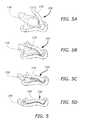
- FIG. 5is a series of images depicting the surgical ligating clip of FIG. 1 being applied securely across a target vessel.
- FIG. 6is a top plan view of a distal portion of a bottom jaw in the clip of the example shown in FIG. 1 .
- FIG. 7is a side elevation of the portion shown in FIG. 6 .
- FIG. 8is a front elevation view of the portion shown in FIG. 7 .
- FIG. 9is a top plan view of a distal portion of a top jaw in the clip of the example shown in FIG. 1 .
- FIG. 10is a side elevation of the portion shown in FIG. 9 .
- FIG. 11is a front elevation view of the portion shown in FIG. 10 .
- FIG. 12is an isometric view of a distal portion of the clip of FIG. 1 shown in a closed configuration.
- FIG. 13is a top plan view of the portion shown in FIG. 12 .
- FIG. 14is a photograph of a side elevation of an example clip in the jaws of an applier with the clip in an open configuration.
- FIG. 15is a photograph of a side elevation of the clip of FIG. 14 in the jaws of an applier with the clip in a partially closed configuration with two parts of the clip jaws in contact.
- FIG. 16is a photograph of a side elevation of the clip of FIG. 14 in the jaws of an applier with the clip further closed and distal portions of the clip jaws in contact.
- FIG. 17is a photograph of a side elevation of the clip of FIG. 14 in the jaws of an applier with the clip almost closed.
- FIG. 18is a photograph of a side elevation of the clip of FIG. 14 in the jaws of an applier with the clip fully closed.
- FIGS. 1 and 2are side and isometric views, respectively, of one example of a surgical ligation clip of the inventions 100 .
- FIG. 3is a close up view of the flexible portion of the clip, identified herein as the hinge section 103 of ligation clip 100 .
- the body of clip 100is comprised of top jaw member 101 and bottom jaw member 102 joined at hinge section 103 .
- jaw members 101 and 102are formed such that they have complementary curved inner or facing surfaces that mate when the clip is in a closed position, but they can also be substantially straight or take other configurations as desired.
- top jaw member 101has an outer surface 104 that is generally convex and an S-shaped inner surface 105 .
- the proximal side of the jaw member 101proximally projects towards the hinge section 103 , forming a heel 121 which may be configured with a radius corner. While heel 121 is shown with a radius corner, other atraumatic configurations may be employed such as, but not limited to, chamfers or the like.
- Bottom jaw member 102has an outer surface 106 that is generally concave and an S-shaped inner surface 107 that approximately matches or conforms to the profile of the inner surface 105 of top jaw member 101 .
- the proximal side of the bottom jaw member 102proximally projects towards the hinge section 103 , and, in the present example, the jaw transition 122 comprises an inner radius or configuration that matches the corner radius or configuration of heel 121 .
- bottom jaw member 102may also project distally and connect to the piercing element 117 and latch 122 .
- the degree of wave or curvature and the length of dorsal or ventral projection(s) of the aforementioned jaw members 101 and 102may be varied along the length of a jaw to further extend or lengthen the clamping surface, thereby allowing the clip 100 to ligate a larger vessel without significantly affecting the overall length of the clip 100 .
- hinge section 103 in the present exampleis flexible over an extended length. While the hinge section can be considered to have a central pivot point, such as CL as described herein, several of the specific examples described herein are configured so that the hinge section is flexible or bends or pivots over a distributed area, for example with an effective or constructive pivot point, and for example flexible between endpoints of a flexible area (as distinct from inflexible elements pivoting about a pivot axis). In one configuration, the distributed flexing or bending is achieved by the provision of a non-circular opening such as the slot 108 described more fully herein. Conversely, if distributed flexing or bending is not desired, flexing or bending about a single axis can be used while adopting other features of the inventions described herein.
- the hinge sectionis offset from the jaw members, for example in a direction of motion of one of the jaw members, for example laterally form the jaw members when the clip is in the closed configuration.
- the hinge section 103can be laterally offset from both of the jaw members, for example at ends of respective lateral extensions of each of the jaw members.
- the hingecan be incorporated at any of a number of selected locations on the lateral extensions of the jaw members, so that the hinge section 103 operates with the jaw members to achieve the desired closing and tissue clasping and tissue moving functions.
- a hinge sectioncan be formed from a plurality of hinge elements (one or more of the hinge elements having the characteristics of the hinge section described herein.
- the plurality of hinge elements together or as an assemblymay be configured to achieve the desired closing and tissue clasping and tissue moving functions.
- the hinge sectionis taken to be bounded on one end by the termination of a slot as described herein at one end of the section and by the termination of a slot at another end of the section, along with the material in between.
- the material in betweenwould be the material between tangent lines 108 C and 108 D of the slot termination points.
- the hinge section boundaryis defined by the terminal ends 108 E and 108 F of the slot, such as the terminal ends of the slot 108 described herein.
- the hinge sectionis bounded by the outer-most termini of the outer slots which contribute to the hinge function.
- the hinge sectionvaries in flexibility across the hinge. For example, when considering different positions across the hinge in a plane of the clip, for example where the jaws of the clip move with respect to each other in the plane of the clip, the flexibility of the hinge at one point may be different than the flexibility of the hinge at another point.
- the hinge sectionis formed with a slot or other extended opening through the material of the clip where proximal portions of the jaws are joined.
- the openingWhen the clip is in a relaxed open state, the opening has a profile or cross-sectional configuration, for example in the plane of the clip. Where the profile of the opening is noncircular, the flexibility of different portions of the hinge segment will be different as a function of location in the hinge segment. For example, a portion of the opening defined by relatively thin walls will be more flexible at that portion than at another portion of the opening defined by thicker walls.
- the hinge section 103is asymmetric relative to the jaws. “Asymmetric” in the context of hinge section 103 being asymmetric relative to the jaws in FIGS. 3A and 3B , is that the hinge section, when positioned relative to the adjacent connection portions between the hinge section and the jaws (in the example of FIGS. 3A-C the dorsally and ventrally extending jaw portions), is asymmetric relative to a curving interface line at the location that the curving interface line intersects the hinge section 103 .
- the curving interface lineis defined by positions equidistant from the jaw surfaces when the jaws are in contact with each other and the curving interface line extends to the hinge section 103 .
- the hinge section 103separates the clip into two jaws and if a vertical (as seen in FIG. 4 ) line 200 divides the clip when in the closed configuration in half longitudinally, then the jaw sections adjacent the hinge section are unequal in mass, and the top jaw section in the example of FIG. 3 (part of top jaw 101 ) is lighter in mass than the bottom jaw section (part of bottom jaw 102 ). Also, as seen in FIG. 4 , more of the opening 108 is on the lower jaw side than on the upper jaw side.
- the hinge section 103connects the proximally-extending sections of the top jaw member 101 and bottom jaw member 102 at respective angularly-extending elements in the form of dorsally- and ventrally-extending jaw elements 101 H and 102 V, respectively, through an elbow 103 A, so that the hinge section 103 is offset from the top jaw member 101 and the bottom jaw member 102 .
- the dorsally- and ventrally-extending jaw elements 101 H and 102 Vextend at an angle to the average direction in which their respective jaws extend.
- the jaw elements 101 H and 102 Vare relatively rigid, compared to the hinge section 103 , and may be formed from the same material as their respective jaw members.
- the hinge section 103comprises a slot 108 that extends through the width of hinge section 103 (and in the present example extends laterally to openings on opposite sides of the hinge section 103 ), an inner hinge surface 109 , and an outer hinge surface 110 .
- Slot 108in one example extends longitudinally, for example between the inner hinge surface 109 , and the outer hinge surface 110 .
- the slot in saggital section(for example, a section parallel to the plane of the drawing of FIG. 1 ) is longer than it is wide, and may be somewhat elliptical or other selected shapes when extended to be straight, though in a resting or relaxed state the slot will take the configuration such as that shown in the drawings, such as FIG. 1 or 14 .
- the slotWhen incorporated as part of the hinge section 103 , the slot will generally have an arcuate configuration, and will be configured to achieve the desired closing motion such as those described herein. Other slot configurations and closing motions are possible as well.
- Slot 108in the present example, is preferably positioned closer to inner surface 109 than to outer surface 110 to provide greater flexibility of the wall adjacent the inner surface 109 when the top jaw member 101 and bottom jaw member 102 are closing together, but it is understood that it can be substantially centered between the inner and outer hinge surfaces, or closer to the outer hinge surface than to the inner hinge surface, depending on the effect and motion desired.
- the thickness 109 A of the wall between the slot 108 and the inner surface 109is less than the thickness 110 A between the slot 108 and the outer surface 110 .
- the adjacent wall along the inner surface 109 of the hinge section 103may comprise a constant wall thickness (i.e., thickness 109 A is substantially constant) or a varying wall thickness (i.e., thickness 109 A varies over the arc length defining the extent of the slot 108 between the dorsally and ventrally extending jaw elements).
- the thinnest section of the wall along the inner surface 109may define the bending point or pivot point CL ( FIGS. 3B & 3C ) of the hinge when jaw members 101 and 102 are closing together, for example the arcuate position of the bending point relative to the slot 108 , and in the present example within the slot 108 .
- the thinnest section of the wall along the inner surface 109is substantially centered along the arcuate extent of the slot 108 .
- the thinnest section of the wall along the inner surface 109is measurably closer to the dorsally extending jaw element, and in other examples, the thinnest section of the wall along the inner surface 109 is measurably closer to the ventrally extending jaw element.
- substantiallyin the context of substantially centered is defined to be providing substantially the same hinge motion for a given clip and applier combination with substantially the same final jaw positions relative to each other, as a clip wherein the thinnest section of the wall along the inner surface 109 is precisely centered in the arcuate extent between the dorsally extending and ventrally extending jaw elements.
- “Not substantially” in the context of not substantially centeredis defined to be not providing substantially the same hinge motion for a given clip and applier combination with substantially the same final jaw positions relative to each other, as a clip wherein the thinnest section of the wall along the inner surface 109 is precisely centered in the arcuate extent between the dorsally extending and ventrally extending jaw elements.
- Having the inner wall thickness 109 A less than that of the outer wallprovides preferential bending or flexing of the inner wall relative to the bending or flexing of the outer wall.
- the preferential bendingprovides a measure of control over how the proximal portions of the jaws come together as the applier (not shown with FIGS. 3-4 , but see the applier with respect to FIGS. 14-18 ) closes the jaws.
- Changing the inner and/or outer wall thicknessescan be achieved by keeping the slot 108 profile constant and moving the slot closer to or further away from the inner surface 109 .
- the inner and/or outer wall thicknessescan be modified by changing the slot 108 profile.
- the radius defining the inner surface 108 Ae.g.
- radius defining the curved surfaceof the slot 108 can be increased or decreased to change the wall thickness 109 A.
- the radius defining the outer surface 108 Bcan be increased or decreased to change the wall thickness 110 A, either separately or in addition to changing the radius defining the inner surface 108 A.
- these radiican be varied as a function of arcuate position to vary the respective thicknesses of the segments they define as a function of arcuate position.
- having the pivot point CL positioned within the opening 108may also help to provide a desired preferential bending. Other bending configurations may be achieved by positioning the pivot point CL within the inner wall or exterior (between the jaws) to the inner wall, or within the outer wall or exterior (outside the jaws) to the outer wall.
- the wall thickness 109 Ais constant over a relatively short arc length compared to the arc length over which the outer wall thickness 110 A is constant, in the present example.
- the wall thickness 109 Aalso can be varied as a function of radial position, or arcuate position along the inner surface 108 A. Varying the wall thickness 109 A will also vary the profile of the inner wall 108 A.
- the wall thickness 110 Acan be varied as a function of radial position, or arcuate position along the outer surface 110 A. Varying the wall thickness 110 A will also vary the profile of the outer wall 108 B.
- the outer wall thickness 110 Ais substantially constant over the arcuate extent of the slot 108 in the example shown in FIGS. 3A-C . Therefore, the thickness 110 A of the wall between the slot 108 and the outer surface 110 is substantially the same between the dorsally extending jaw element 101 H and the ventrally extending jaw element 102 V. In this example specifically, the intermediate, approximately 75% of the wall between the slot 108 and the outer surface 110 has substantially the same thickness, while the thickness at the end portions of the slot 108 increase, for example to allow the endpoints of the slot 108 to have a curvature.
- substantiallyin the context of substantially constant thickness 110 A of the outer wall is a wall thickness of the outer wall that is constant over at least 50% of the outer wall over the extent of the slot or opening 108 .
- the thinnest section of the wall along the outer surface 110may help to define the pivot point CL, and in one example a center point or intermediate point of the thinnest section of the wall on the outer surface 110 may be aligned with the pivot point CL and the thinnest section of the wall on the inner surface 109 .
- the center point or intermediate point of the thinnest section of the wall on the outer surface 110may be un-aligned with the pivot point CL and the thinnest section of the wall on the inner surface 109 .
- the ventral jaw section 102 V of the bottom jaw member 102further comprises a plurality of teeth 111 located on inner surface 109 .
- an axis (not shown) bisecting a respective tooth 111is positioned at an angle to a line normal to the surface to which the tooth is attached (in other words, off perpendicular).
- the axisis angled toward the top jaw member 101 , as opposed to the bottom jaw member. This angle helps to reduce the likelihood that tissue will migrate along the surface to which the tooth is attached toward the bottom jaw member 102 . This angle also helps to reduce the resistance to tissue movement/ingress into the cavity toward the inner surface 109 when the tissue is placed into the clip and/or as the clip is being closed.
- the angle of the axis bisecting the tooth(when viewed from the side such as in FIGS. 1, 3-5 ) can be selected to increase the ability of the tooth to resist tissue movement/egress out of the clip or out of the area in which the tooth is located.
- closing the top jaw 101 and/or the bottom jaw 102initiates the rotation of the top jaw 101 around the imaginary pivot point CL ( FIGS. 3B and 3C ) relative to the bottom jaw 102 .
- CLis the point of intersection of all lines through respective points on the top jaw 101 when the jaw is open ( FIG. 3B ) and when the jaw is closed ( FIG. 3C ).
- the angular position of heel 121 relative to the bottom jawdecreases from angle ⁇ A to ⁇ B relative to the origin ⁇ C , or the line when the clip is in the closed position.
- heel 121is at a position closer to the inner surface 107 of the bottom jaw member 102 while the opening at the distal end of the jaw members 101 and 102 remains wider (see for example FIG. 5B ).
- the closing of heel 121 against or closely adjacent the inner surface 107 (and/or proximally relative to the hinge section 103 )causes the vessel or tissue to be securely engaged against the inner surface 107 or pinched between the adjacent surfaces of the top and bottom jaws, reducing the likelihood of the tissue or vessel slipping out of the clip 100 as the jaws are closed and locked in place (locked together).
- the teeth 114 around the perimeter of the heel 121help to keep the tissue or vessel from slipping out of the clip, or at least distally.
- the teeth 114also help retain the tissue or vessel based on an angular orientation of the bisecting axis directed proximally (positioned at an angle to a line normal to the surface, for example 107 B shown in FIG. 7 , to which the tooth is attached (in other words, off perpendicular in a proximal direction).
- the action of continuing to close the jawscreates further rotation or angular movement of the heel 121 towards the proximal side of the clip 100 , dragging or pulling the tissue or vessel proximally.
- angular position ⁇ Cthe jaw members 101 and 102 are fully closed.
- CLis approximately centered between the inner and outer walls 108 A and 108 B, and is approximately centered along an arc between the ends of the slot 108 (as seen in FIG. 3B ), when the slot 108 is positioned horizontally and vertically (when viewed as shown in FIG. 3B ) as shown.
- the slot 108starts approximately vertically at the vertical (as viewed in FIG. 3B ) leg 102 V extending ventrally from the rest of the bottom jaw 102 .
- the slotextends in an arc along a hinge leg 103 V to a horizontal hinge leg 103 H (as viewed in FIG.
- FIGS. 14-18Another example of a hinge location and configuration is shown in FIGS. 14-18 , discussed more fully below.
- the junction of the horizontal leg 101 H and the adjacent proximal portion of the top jaw 101forms the heel 121 .
- the surface configuration of the inner portion of the heel 121can also affect the rate of closure of the spacing 121 A. (Rate in the context of movement of the heel 121 and decrease in the spacing 121 A is defined below.) If the curvature of the inner surface 109 at the horizontal leg 101 H is more concave than as shown in FIG. 3B , the heel 121 will be protruding into the cavity defined by the inner wall 109 . If more concave, the wall thickness 109 A may be smaller resulting in a higher rate of closure of the spacing 121 A.
- the point of eccentricity and its position along the heel 121may also affect the rate of closure or decrease of the spacing 121 A.
- These aspects of the heel configurationcan be modified as desired to produce the desired effect on tissue in the cavity when the jaws are closing.
- the length of the vertical leg 102 Vcan be increased while keeping the overall slot position the same, thereby increasing the spacing 121 A, if all other parameters remain the same.
- the length of the horizontal leg 101 Hcan be increased while keeping the overall slot position the same to increase the size of the cavity in the hinge area for receiving tissue.
- the legs 101 H and/or 102 Vcan remain constant while moving the position of the slot 108 , such as is illustrated in the configuration of FIGS. 14-18 closer to the top jaw, which may also be considered shortening the horizontal leg 101 H and lengthening the vertical leg 102 V, or closer to the bottom jaw (not shown).
- the spacing 121 Adecreases.
- the rate at which the spacing 121 A decreasesmay be determined at least in part by the position of CL.
- “rate”means the rate of closure or decrease in spacing 121 A relative to the angular rate of closure of the top and bottom jaws. For example, positioning CL higher within the slot 108 (but still centered between the inner and outer walls 108 A and 108 B, respectively) would decrease the rate of closure of the spacing 121 A. This is because CL is positioned more distally and also ventrally from the bottom jaw 102 .
- Positioning CL lower within the slot 108would increase the rate of closure.
- the rate of closurewill also be affected by the thickness 109 A of the wall between the slot 108 and the inner wall surface 109 .
- Other factorsmay also be used to adjust or modify the rate of closure.
- thickness of the tissue that may be inserted between the heel 121 and the surface 107may change the decrease in the spacing 121 A. In one configuration, the distance 121 A is brought to its minimum before the jaws are closed and locked.
- the heel 121is positioned and configured to have a relatively short distance of travel to the bottom jaw 102 , while having a relatively wide initial starting spacing when the top and bottom jaws are open for more easily receiving tissue into the cavity (adjacent the inner surface 109 ). Such a configuration is made more easy with a higher rate of closure.
- Tooth pair 120(which may resemble a fang) may be provided at the distal end of inner surface 105 and may be configured such that it has facing surfaces defining an edge that generally extends and points towards the bottom jaw member 102 .
- the tooth pair 120may be configured to be sharp enough to puncture tissue in conjunction with the piercing element 117 described below.
- a pair of laterally-extending cylindrical bosses 115 located adjacent the distal section 112may be provided on both sides of top jaw member 101 , for example to be complimentary to respective surfaces on an applier used to apply the ligating clip.
- Bottom jaw member 102comprises a distal section 113 that may have a piercing feature and a latching feature configured to mate with the latching feature of the top jaw member 101 .
- Distal section 113comprises a piercing element 117 having a tip 117 A disposed opposite latch 123 .
- the piercing element 117is generally configured such that it extends to a narrow portion or point that is facing or pointed towards the top jaw member 101 .
- the piercing element 117may be configured to be sharp enough to puncture tissue during normal use.
- a pair of laterally-extending cylindrical bosses 116 located adjacent the distal section 113are provided on both sides of bottom jaw member 102 , for example to be complimentary to respective surfaces on an applier used to apply the ligating clip.
- the piercing element 117is narrowed or pointed with a tip sufficient to puncture tissue during normal use.
- the piercing elementmay be a pointed bevel, cone, trapezoid shape or other shape providing the desired tip geometry.
- the geometrymay have two or more faces or sides in which an inclusive angle of opposing faces or sides is 150° or less (for example, as shown in FIGS. 14-18 ), but an angle of 90° or less increases the ease with which tissue can be punctured with the piercing element, while an angle of 60° or less provides an even sharper piercing element.
- any one, two or three of the angles ⁇ 1, ⁇ 2, and ⁇ 3can be configured to have the angles recited.
- the piercing elementmay have a durometer of at least 50 Shore D in order to provide a sufficient hardness to puncture the tissue.
- Other piercing element configurationscan also be used to produce a tip sufficient to puncture tissue during normal use.
- the piercing element 117may be an integral part of the whole clip structure as discussed in these examples such that the ligation clip 100 is only made from a single material.
- itmay be constructed from different materials including but not limited to metals like stainless steel, titanium, nickel titanium, gold, platinum, cobalt, chromium, and the like, or non metal including plastics with increased hardness properties as compared to the material used to make the remaining clip.
- the piercing element 117may be assembled or connected to the distal section of the bottom jaw 102 (not shown) by means of methods commonly known in the art such as adhesive bonding, insert molding, ultrasonic welding, hot melt, and the like. Yet another alternative means to strengthen the structure of the piercing element 117 is by coating or plating the surface (not shown) with a metallic material commonly known in the art such as gold, platinum, chrome, nickel, or the like or with a harder grade of polymeric material using processes also commonly known in the art.
- Inner surfaces 105 and 107may further comprise a plurality of teeth 114 .
- the teeth 114 and 111may be configured with other orientations and shapes that enable effective securement of a vessel or tissue when the clip is closed in the locked position. These alternative configurations may include, but are not limited to, domes, pyramids, bosses and notches, tongue(s) and groove(s), similar features, and/or combinations thereof.
- any one tooth (or more than one tooth)can be configured such that a bisecting axis is oriented at an angle to the surface supporting the tooth (or at an angle to a line running parallel to the surface supporting the tooth).
- all (and therefore a majority) of the teethhave their bisecting axes (for example 114 A in FIG. 7 ) angled in a proximal direction, or in such a direction that reduces the possibility of tissue moving distally or outward of the clip or along a surface of a jaw in a direction that would lead to the tissue moving outward of the clip.
- each toothcan extend the entire width of the jaw, or beyond, or can extend less than the entire width. For example of less than the entire width, a tooth can extend only half way across the width of the jaw. Moreover, every other or every second tooth can extend halfway inward from one side while the remaining teeth on a jaw can extend halfway inward from the other side (alternating). Additionally, on the top jaw, the linear density is higher at a proximal portion of the jaw than at a distal portion of the jaw.
- the teeth configuration (i.e. any feature described herein with respect to a given tooth or combination of teeth) on one jawcan be different than the corresponding teeth configuration on the immediately adjacent portion of the opposite jaw, when the jaws are closed.
- one jawhas a length of surface without any teeth and the other jaw has a similar length of surface facing it that has two or more teeth.
- the bottom jawhas a length of surface 107 A ( FIG. 1 ) where the facing surface on the top jaw has seven teeth.
- the bare surface 107 Ais configured to allow tissue to move along it relatively freely relative to the opposite surfaces on the other jaw. For example, where the heel 121 is closely adjacent the bottom jaw, and the bare surface 107 A, movement of the top jaw and the adjacent teeth on the heel 121 and grab and move tissue into the cavity adjacent the inner surface 109 while the tissue slides along the surface 107 A. As the heel 121 moves into the cavity, other teeth on the top jaw move into position opposite the surface 107 A. This configuration promotes grabbing and pulling the tissue into the cavity.
- the smooth surface 107 Ais bordered on both sides (proximally and distally) by one or more teeth.
- the length of the smooth surface 107 Ais greater than at least twice the smallest spacing between adjacent teeth on the clip. Additionally, when the jaws are facing each other, such as when the clip is closed, at least two teeth from the top jaw are positioned opposite the smooth surface 107 A without an intervening tooth on the bottom jaw. Other configurations are also possible.
- cylindrical bosses 115 and 116are depicted as externally projecting features in these figures, it is also contemplated that low-profile bosses or recesses such as those described in U.S. Pat. Publication US20090088783, incorporated herein by reference in its entirety, may be employed to facilitate placement of clips such as those described herein about a target vessel when used with a complementary applier.
- FIG. 4is a side view of an example of the inventions depicted in FIGS. 1-3 in the closed position.
- piercing element 117is fully embedded within channel 124 of shroud 118 , forming atraumatic surface 125 .
- the tip 117 Ais at or below (as viewed in FIG. 4 ) a tangent line 118 A to the shroud 118 (see FIG. 4 ). In this manner the tip of the piercing element 117 is not exposed to adjacent tissue that may potentially be lacerated, cut, severed, or serrated by the sharp edges and/or points of the piercing element 117 .
- Piercing element 117 embedded within channel 124also serves as a locking feature that prevents or limits latch 131 from sliding or disengaging sideways or laterally during normal operation.
- the remaining external surfaces of ligation clip 100do not have any sufficiently sharp or pointed features that may catch, tear, or lacerate surrounding tissues.
- the distance between the centerline 115 A of the cylindrical boss 115 , and applier jaw imaginary arc-shaped path 128controls the amount of outward deflection 126 .
- the imaginary path 128is the track followed by the cylindrical boss 115 and 116 when they are held in the applier jaws, thus the top jaw member 101 shifts proximally, causing the proximal side of bottom jaw member 102 and the adjacent hinge section 103 A to deflect outward (compare FIGS. 16 and 17 ).
- the applierfurther closes the clip 100 A, the distal side of bottom jaw member 102 deflects outward as depicted by the imaginary line 127 (compare FIGS. 16 and 17 ).
- the deflectionis a result of the piercing element 117 sliding outwards or distally along the groove 119 .
- FIG. 5is a series of schematics ( 5 A- 5 D) depicting the placement and closure of the ligation clip 100 about a target vessel 129
- FIGS. 14-18show the use of a ligation clip in conjunction with an applier for closing the ligation clip.
- target vessel 129further comprises extraneous tissue 130 (e.g. connective tissue, fat, fibrous scar tissue, etc.) that would traditionally hinder or prevent the closure of ligation clips known in the art.
- FIG. 14shows a fully open clip positioned in the jaws of an applier and
- FIG. 5Ashows the ligation clip 100 approximated about the target vessel 129 in a fully-open configuration.
- the heel 121 at a proximal portion of the first jawis spaced apart from the second jaw 102 , but closer to the second jaw than a distal portion of the first jaw, for example that portion including bosses 115 .
- the teeth 114 on the inner surfaces 105 and 107engage and grip the surface of target vessel 129 .
- FIG. 5B and FIG. 15show ligation clip 100 in a semi-closed state.
- the teeth 114 on inner surface 107 of jaw member 102secure the base of the target vessel 129 in place while the pivoting motion of jaw member 101 about hinge section 103 (or 103 A in FIGS.
- FIG. 14-18causes the teeth 114 disposed around the heel 121 on inner surface 105 to engage against and pull the upper surface of target vessel 129 towards the inner surface 109 of hinge section 103 / 103 A.
- the heel 121 and the teeth on the surface thereofmove proximally the tissue along the smooth surface 107 A of the bottom jaw member 102 .
- the piercing element 117begins to engage extraneous tissue 130 .
- FIG. 5C and FIGS. 16-17show the ligation clip 100 in an almost completely closed state.
- FIG. 17shows the distal section 113 of the second jaw 102 flexing outward or distally, as well as a portion of the hinge section 103 flexing proximally.
- FIG. 18shows the ligation clip 100 fully closed, with the heel 121 fully within the cavity and the hinge section 103 A fully flexed (hinge section 103 would be analogous) and the latching mechanism 123 and 131 fully engaged.
- hinge section 103 in this exampleis asymmetric relative to the jaws. As see most clearly in FIG. 18 , when positioned relative to the adjacent connection portions between the hinge section and the jaws and the jaws are closed, the hinge section is asymmetric relative to a curving interface line at the location that the curving interface line intersects the hinge section 103 .
- the curving interface lineis defined as above with respect to FIGS. 3A-3C . In the example shown in FIG. 18 , there is more of the opening 108 on the top jaw side than on the bottom jaw side. Additionally, in the present example, the hinge section 103 separates the clip into two jaws and if a vertical line similar to the vertical line 200 in FIG.
- the ligation clip 100may be made of a metallic or non-metallic biocompatible material including, but not limited to stainless steel, titanium, acetal, polyethylene, nylon, peek, Teflon, polycarbonate, alloys or combination thereof, and the like suitable for a long term or permanent implant. Polymer materials may be non-resorbable (i.e. permanent implant) or resorbable (i.e. degrades over a period of time).
- the ligation clip 100may be made in various sizes to allow ligation of different sizes of vessel or tissue. All design features, clip functionality, and methods of use and operation described within the details of this disclosure remain applicable to the other sizes. These various sizes of ligation clips can respectively be used to ligate a variety of vessel sized, with the largest diameter of about 16 mm.
Landscapes
- Health & Medical Sciences (AREA)
- Surgery (AREA)
- Life Sciences & Earth Sciences (AREA)
- Heart & Thoracic Surgery (AREA)
- Nuclear Medicine, Radiotherapy & Molecular Imaging (AREA)
- Vascular Medicine (AREA)
- Engineering & Computer Science (AREA)
- Biomedical Technology (AREA)
- Reproductive Health (AREA)
- Medical Informatics (AREA)
- Molecular Biology (AREA)
- Animal Behavior & Ethology (AREA)
- General Health & Medical Sciences (AREA)
- Public Health (AREA)
- Veterinary Medicine (AREA)
- Surgical Instruments (AREA)
Abstract
Description
Claims (34)
Priority Applications (1)
| Application Number | Priority Date | Filing Date | Title |
|---|---|---|---|
| US14/353,022US9855053B2 (en) | 2011-10-20 | 2012-10-22 | Ligation clip |
Applications Claiming Priority (3)
| Application Number | Priority Date | Filing Date | Title |
|---|---|---|---|
| US201161549740P | 2011-10-20 | 2011-10-20 | |
| US14/353,022US9855053B2 (en) | 2011-10-20 | 2012-10-22 | Ligation clip |
| PCT/US2012/061384WO2013059826A1 (en) | 2011-10-20 | 2012-10-22 | Ligation clip |
Related Parent Applications (1)
| Application Number | Title | Priority Date | Filing Date |
|---|---|---|---|
| PCT/US2012/061384A-371-Of-InternationalWO2013059826A1 (en) | 2011-10-20 | 2012-10-22 | Ligation clip |
Related Child Applications (1)
| Application Number | Title | Priority Date | Filing Date |
|---|---|---|---|
| US15/845,825ContinuationUS10820909B2 (en) | 2011-10-20 | 2017-12-18 | Ligation clip |
Publications (2)
| Publication Number | Publication Date |
|---|---|
| US20140243862A1 US20140243862A1 (en) | 2014-08-28 |
| US9855053B2true US9855053B2 (en) | 2018-01-02 |
Family
ID=48141476
Family Applications (3)
| Application Number | Title | Priority Date | Filing Date |
|---|---|---|---|
| US14/353,022Active2034-06-21US9855053B2 (en) | 2011-10-20 | 2012-10-22 | Ligation clip |
| US15/845,825Active2033-03-22US10820909B2 (en) | 2011-10-20 | 2017-12-18 | Ligation clip |
| US17/086,923PendingUS20210045745A1 (en) | 2011-10-20 | 2020-11-02 | Ligation clip |
Family Applications After (2)
| Application Number | Title | Priority Date | Filing Date |
|---|---|---|---|
| US15/845,825Active2033-03-22US10820909B2 (en) | 2011-10-20 | 2017-12-18 | Ligation clip |
| US17/086,923PendingUS20210045745A1 (en) | 2011-10-20 | 2020-11-02 | Ligation clip |
Country Status (6)
| Country | Link |
|---|---|
| US (3) | US9855053B2 (en) |
| EP (3) | EP3305217A1 (en) |
| JP (3) | JP6754169B2 (en) |
| AU (2) | AU2012325718B2 (en) |
| CA (1) | CA2852774C (en) |
| WO (1) | WO2013059826A1 (en) |
Cited By (29)
| Publication number | Priority date | Publication date | Assignee | Title |
|---|---|---|---|---|
| USD838847S1 (en)* | 2017-10-20 | 2019-01-22 | Dahong Zhang | Hemostatic clamp |
| US10548609B2 (en) | 2016-08-03 | 2020-02-04 | Teleflex Medical Incorporated | Surgical ligation clip |
| US10820909B2 (en) | 2011-10-20 | 2020-11-03 | Teleflex Life Sciences Pte. Ltd. | Ligation clip |
| USD907200S1 (en) | 2019-08-05 | 2021-01-05 | Covidien Lp | Ligation clip |
| USD907203S1 (en)* | 2019-08-02 | 2021-01-05 | Covidien Lp | Ligation clip |
| USD907204S1 (en)* | 2019-08-02 | 2021-01-05 | Covidien Lp | Ligation clip |
| US10925616B2 (en) | 2017-03-21 | 2021-02-23 | Teleflex Medical Incorporated | Clip applier with replaceable tips |
| US10932788B2 (en) | 2018-04-11 | 2021-03-02 | Covidien Lp | Ligation clip with latching and retention features |
| US10932789B2 (en) | 2018-04-11 | 2021-03-02 | Covidien Lp | Ligation clip with latching and retention features |
| US10945740B2 (en) | 2017-06-22 | 2021-03-16 | Teleflex Medical Incorporated | Surgical clip |
| US11033279B2 (en) | 2018-04-24 | 2021-06-15 | Covidien Lp | Ligation clip with retention features |
| US11160559B2 (en) | 2017-03-21 | 2021-11-02 | Teleflex Medical Incorporated | Clip applier with stabilizing member |
| US11266408B2 (en) | 2017-03-21 | 2022-03-08 | Teleflex Medical Incorporated | Clip applier having stabilizing member |
| US11304703B2 (en) | 2018-05-25 | 2022-04-19 | Covidien Lp | Ligation clip removal device |
| US11304704B2 (en) | 2018-08-22 | 2022-04-19 | Covidien Lp | Surgical clip applier and ligation clips |
| US11317923B2 (en) | 2018-08-13 | 2022-05-03 | Covidien Lp | Ligation clip with improved hinge |
| US11395660B2 (en) | 2019-08-05 | 2022-07-26 | Covidien Lp | Stackable ligation clip |
| US11471165B2 (en) | 2019-05-08 | 2022-10-18 | Covidien Lp | Ligation clip cartridge |
| US11534177B2 (en) | 2017-03-21 | 2022-12-27 | Teleflex Medical Incorporated | Flexible stabilizing member for a clip applier |
| US11607227B2 (en) | 2017-03-21 | 2023-03-21 | Teleflex Medical Incorporated | Surgical clip and clip applier |
| US11648014B2 (en)* | 2017-11-14 | 2023-05-16 | Teleflex Medical Incorporated | Surgical clip |
| US11696764B2 (en) | 2020-01-31 | 2023-07-11 | Covidien Lp | Ligation clip with controlled tissue compression |
| US11707282B2 (en) | 2019-07-02 | 2023-07-25 | Covidien Lp | Multi-piece ligation clip |
| USD993411S1 (en) | 2017-11-03 | 2023-07-25 | Covidien Lp | Ligation clip with controlled tissue compression |
| US11992222B2 (en) | 2019-12-19 | 2024-05-28 | Teleflex Medical Incorporated | Surgical clip |
| US12023041B2 (en) | 2017-03-21 | 2024-07-02 | Teleflex Medical Incorporated | Clip applier |
| US12114866B2 (en) | 2020-03-26 | 2024-10-15 | Covidien Lp | Interoperative clip loading device |
| US12279774B2 (en) | 2018-09-26 | 2025-04-22 | Teleflex Medical Incorporated | Clip applier with stabilizing member |
| US12318094B2 (en) | 2019-09-26 | 2025-06-03 | Teleflex Medical Incorporated | Clip applier |
Families Citing this family (25)
| Publication number | Priority date | Publication date | Assignee | Title |
|---|---|---|---|---|
| NL2010046C2 (en)* | 2012-12-21 | 2014-06-24 | Basiq B V | Surgical cutter. |
| CN103892884B (en)* | 2014-04-17 | 2016-02-24 | 苏州奥芮济医疗科技有限公司 | Metallic blood vessel folder of a kind of orientable degraded and absorbed and preparation method thereof |
| KR102365594B1 (en)* | 2015-03-26 | 2022-02-22 | 주식회사 메타바이오메드 | Surgical Clip |
| US10111656B2 (en)* | 2015-05-11 | 2018-10-30 | Covidien Lp | Tissue fastening system and method |
| US10327762B2 (en) | 2015-07-17 | 2019-06-25 | Suturegard Medical, Inc. | Suture locks |
| US10463360B2 (en) | 2015-07-17 | 2019-11-05 | Suturegard Medical, Inc. | Suture locks |
| WO2017017587A2 (en) | 2015-07-24 | 2017-02-02 | Cliptip Medical Ltd | Thickness-adjustable hemostatic clips, clip appliers, and applications thereof |
| JP2018537168A (en)* | 2015-11-20 | 2018-12-20 | クリップティップ メディカル リミテッド | Surgical clip and its placement control |
| US10265079B2 (en)* | 2016-04-28 | 2019-04-23 | Grena Usa Llc | Polymeric ligating clip |
| US10258345B2 (en)* | 2016-05-25 | 2019-04-16 | Geoff Brown | Surgical ligation clip |
| US10201353B2 (en) | 2017-02-03 | 2019-02-12 | Pavel Menn | Ligation clip |
| USD808522S1 (en) | 2017-07-11 | 2018-01-23 | Vesolock Medical, Llc | Latching ends of a polymer ligating clip |
| WO2019089440A1 (en) | 2017-10-30 | 2019-05-09 | Teleflex Medical Incorporated | Latching wire clip |
| US20190223874A1 (en)* | 2018-01-24 | 2019-07-25 | Covidien Lp | Ligation clip with tissue retention features |
| USD845588S1 (en)* | 2018-06-22 | 2019-04-16 | Near the Heart, LLC | Underwire retainer |
| MX2018008202A (en)* | 2018-06-29 | 2019-12-30 | Viretec Gestion Y Desarrollo S A De C V | Device for blood vessel occlusion and haemorrhage control and method for placement and removal thereof. |
| KR102092347B1 (en)* | 2018-07-16 | 2020-03-23 | 주식회사 엔도비전 | Banana clip for removing hemorrhoids and Surgical tool set including the same |
| KR102852635B1 (en)* | 2018-11-16 | 2025-08-29 | 텔리플렉스 메디컬 인코포레이티드 | Surgical clip |
| CN113613567A (en)* | 2019-03-18 | 2021-11-05 | 国立大学法人熊本大学 | Fixing clamp for residual end of organ excision part |
| US20210030420A1 (en)* | 2019-08-02 | 2021-02-04 | Covidien Lp | Ligation clip with improved latch mechanism |
| US11246600B1 (en)* | 2020-08-13 | 2022-02-15 | Geoff Brown | Surgical ligation clip with advanced incising means and bifurcated guide track |
| CN112155636A (en)* | 2020-10-13 | 2021-01-01 | 常州安康医疗器械有限公司 | Full-degradable metal-based vascular tissue closing clamp for endoscope |
| AU2022270758A1 (en)* | 2021-05-07 | 2023-11-23 | Teleflex Medical Incorporated | Device and method for unlatching a surgical clip |
| KR102705086B1 (en)* | 2022-01-26 | 2024-09-11 | 주식회사 티플랜트 | Medical ligation clips |
| GB2628643A (en)* | 2023-03-31 | 2024-10-02 | Newtec Vascular Products Ltd | Improvements in or relating to surgical clips |
Citations (84)
| Publication number | Priority date | Publication date | Assignee | Title |
|---|---|---|---|---|
| US3825012A (en)* | 1973-04-13 | 1974-07-23 | H Nicoll | Reusable umbilical cord clamp for veterinary use |
| US3867944A (en)* | 1972-10-27 | 1975-02-25 | Wood Ernest C | Hemostatic clip and applicator therefor |
| JPS56151034A (en) | 1980-02-25 | 1981-11-21 | Ethicon Inc | Plastic double latch clamp clip |
| US4345600A (en)* | 1980-08-04 | 1982-08-24 | Senco Products, Inc. | Purse-stringer |
| US4418694A (en)* | 1979-06-18 | 1983-12-06 | Ethicon, Inc. | Non-metallic, bio-compatible hemostatic clips |
| US4450840A (en)* | 1982-02-26 | 1984-05-29 | Ethicon, Inc. | Ligating clip with flanged base having a recessed engaging face |
| US4476865A (en)* | 1982-02-12 | 1984-10-16 | Ethicon, Inc. | Non-metallic, bio-compatible hemostatic clips |
| US4487205A (en)* | 1982-04-26 | 1984-12-11 | Ethicon, Inc. | Non-metallic, bio-compatible hemostatic clips |
| US4519392A (en)* | 1982-10-12 | 1985-05-28 | Lingua Robert W | Hemostasing muscle clips for needleless surgery |
| US4527562A (en)* | 1979-06-18 | 1985-07-09 | Ethicon, Inc. | Non-metallic, bio-compatible hemostatic clips |
| US4550729A (en)* | 1981-08-27 | 1985-11-05 | Ethicon, Inc. | Non-metallic, bio-compatible hemostatic clips with interlocking latch means |
| US4579118A (en)* | 1983-06-01 | 1986-04-01 | Ethicon, Inc. | Hemostatic clip with penetration means |
| US4589626A (en)* | 1985-03-13 | 1986-05-20 | Bioresearch Inc. | Hose clamp |
| EP0201344A2 (en) | 1985-05-10 | 1986-11-12 | Ethicon, Inc. | Ligating clip and clip applier |
| US4638804A (en)* | 1980-02-25 | 1987-01-27 | Ethicon, Inc. | Double-latched non-metallic, bio-compatible hemostatic clip |
| US4712549A (en) | 1985-07-01 | 1987-12-15 | Edward Weck & Co. | Automatic hemostatic clip applier |
| US4716886A (en)* | 1986-05-01 | 1988-01-05 | Norman Schulman | Umbilical cord clamp and cutters |
| US4726372A (en) | 1986-09-19 | 1988-02-23 | Metatech Corporation | Hemostatic clip |
| US4822348A (en) | 1987-05-13 | 1989-04-18 | Donn Casey | Surgical clips |
| EP0314064A2 (en) | 1987-10-26 | 1989-05-03 | Pilling Weck Incorporated | Plastic ligating clips |
| US4936447A (en) | 1989-09-26 | 1990-06-26 | Horizon Surgical Inc. | Hemostatic clip holder |
| US4961499A (en) | 1990-01-04 | 1990-10-09 | Pilling Co. | Hemostatic clip cartridge |
| US4972949A (en) | 1989-09-26 | 1990-11-27 | Horizon Surgical, Inc. | Hemostatic clip holder for small clips |
| US5026382A (en) | 1990-08-27 | 1991-06-25 | Horizon Surgical, Inc. | Hemostatic clip |
| JPH03178648A (en) | 1989-10-17 | 1991-08-02 | Edward Weck Inc | Penetration type plastic clip for clipper |
| US5047038A (en) | 1985-07-01 | 1991-09-10 | Edward Weck Incorporated | Automatic hemostatic clip applier |
| US5046611A (en) | 1990-10-22 | 1991-09-10 | Edward Weck Incorporated | Hemostatic clip cartridge |
| US5100416A (en) | 1989-10-17 | 1992-03-31 | Edward Weck Incorporated | Ligating clip applying instrument |
| US5104395A (en) | 1989-07-03 | 1992-04-14 | Edward Weck Incorporated | Automatic hemostatic clip applicator |
| US5112343A (en) | 1991-04-05 | 1992-05-12 | Edward Weck Incorporated | Endoscopic clip appliers |
| US5127915A (en)* | 1984-10-29 | 1992-07-07 | Mattson Philip D | Surgical instrument for severing and clamping an umbilical cord |
| US5160339A (en)* | 1991-06-18 | 1992-11-03 | Ethicon, Inc. | Endoscopic suture clip |
| US5201416A (en) | 1990-10-22 | 1993-04-13 | Edward Weck Incorporated | Hemostatic clip cartridge |
| US5234449A (en)* | 1992-07-16 | 1993-08-10 | Ethicon, Inc. | Suture clip with reduced hinge mass |
| US5279416A (en) | 1992-06-05 | 1994-01-18 | Edward Weck Incorporated | Ligating device cartridge with separable retainer |
| US5330442A (en)* | 1992-10-09 | 1994-07-19 | United States Surgical Corporation | Suture retaining clip |
| US5330487A (en) | 1992-12-17 | 1994-07-19 | Tfi Acquistion Corp. | Drive mechanism for surgical instruments |
| US5366458A (en)* | 1990-12-13 | 1994-11-22 | United States Surgical Corporation | Latchless surgical clip |
| US5575802A (en)* | 1994-01-15 | 1996-11-19 | Femcare (Cyprus) Limited | Medical clip |
| US5667516A (en)* | 1995-05-01 | 1997-09-16 | Allen; Sean A. | Mechanism for cutting an umbilical cord |
| US5713912A (en)* | 1995-08-30 | 1998-02-03 | Stress Management, Inc. | Ligating clip having ramp-shaped vessel clamping members and tool for applying same |
| US5722982A (en)* | 1996-09-26 | 1998-03-03 | University Technology Corporation | Strabismus surgery apparatus and method |
| US5810853A (en)* | 1996-01-16 | 1998-09-22 | Yoon; Inbae | Knotting element for use in suturing anatomical tissue and methods therefor |
| US5846255A (en)* | 1996-01-31 | 1998-12-08 | Casey Medical Products Limited | Surgical clip |
| US5908430A (en) | 1995-06-07 | 1999-06-01 | Appleby; Timothy | Easy loading hemostatic clip and cartridge |
| US5921991A (en)* | 1997-10-23 | 1999-07-13 | Biomax Technologies Inc. | Multi-colored umbilical cord clamp |
| US5925052A (en)* | 1996-06-26 | 1999-07-20 | Simmons; Paul L. | Umbilical surgical scissors |
| US6391035B1 (en) | 2000-03-24 | 2002-05-21 | Timothy Appleby | Hemostatic clip removal instrument |
| US20020068946A1 (en)* | 2000-12-06 | 2002-06-06 | Kortenbach Juergen A. | Apparatus for the endoluminal treatment of gastroesophageal reflux disease (GERD) |
| US6419682B1 (en)* | 2000-03-24 | 2002-07-16 | Timothy Appleby | Hemostatic clip cartridge |
| US20020111640A1 (en)* | 2001-02-13 | 2002-08-15 | Krause William R. | Urological device for the incontinent male |
| US6537289B1 (en) | 1999-11-29 | 2003-03-25 | General Surgical Innovations, Inc. | Blood vessel clip applicator |
| US20040059359A1 (en)* | 2002-09-20 | 2004-03-25 | Wilson Donald F. | Ligating clip with integral penetrating hook |
| US6824547B2 (en) | 2001-07-13 | 2004-11-30 | Pilling Weck Incorporated | Endoscopic clip applier and method |
| US6880699B2 (en) | 2002-08-27 | 2005-04-19 | Pilling Weck Incorporated | Cartridge for holding asymmetric surgical clips |
| US20050165423A1 (en)* | 2004-01-23 | 2005-07-28 | Pilling Weck Incorporated | Ligating clip with integral tissue-securing mechanism |
| US20050165421A1 (en)* | 2004-01-22 | 2005-07-28 | Pilling Weck Incorporated | Ligating clip with integral interlocking latch mechanism |
| US20050165422A1 (en)* | 2004-01-22 | 2005-07-28 | Pilling Weck Incorporated | Ligating clip with integral cutting guide |
| US7001412B2 (en) | 2004-01-28 | 2006-02-21 | Pilling Weck Incorporated | Surgical clip with integral suture-securing mechanism |
| US7052504B2 (en) | 2002-11-19 | 2006-05-30 | Teleflex Incorporated | Automated-feed surgical clip applier and related methods |
| WO2006102578A1 (en) | 2005-03-24 | 2006-09-28 | Pilling Weck Incorporated | Reduced closure force ligating clip |
| US20060217749A1 (en)* | 2005-03-24 | 2006-09-28 | Pilling Weck Incorporated | Reduced closure force ligating clip |
| US7131977B2 (en) | 2002-08-27 | 2006-11-07 | Pilling Weck Incorporated | Apparatus and method for removing a clip |
| US20070083218A1 (en)* | 2005-10-12 | 2007-04-12 | A Morris Steven | Coated ligating clip |
| US7211091B2 (en) | 2002-08-27 | 2007-05-01 | Pilling Weck Incorporated | Fingertip-actuated surgical clip applier and related methods |
| US7211092B2 (en) | 2002-11-19 | 2007-05-01 | Pilling Weck Incorporated | Automated-feed surgical clip applier and related methods |
| US20070118161A1 (en)* | 2005-11-22 | 2007-05-24 | Kennedy Daniel L | Non-snag polymer ligating clip |
| US20070149989A1 (en)* | 2005-12-22 | 2007-06-28 | Santilli Albert N | Vascular and Intestinal Occlusion |
| US7402164B2 (en)* | 2001-06-05 | 2008-07-22 | Watson Jr Richard L | Umbilical cord clamp and cutter |
| US20080312670A1 (en)* | 2006-01-11 | 2008-12-18 | Aesculap Ag | Surgical ligature clip |
| EP2074954A1 (en) | 2007-12-31 | 2009-07-01 | Teleflex Medical Incorporated | Ligation clip with flexible clamping feature |
| US7585304B2 (en) | 2004-02-02 | 2009-09-08 | Teleflex Medical Incorporated | Endoscopic clip applying apparatus with improved aperture for clip release and related method |
| US20090240266A1 (en)* | 2008-03-21 | 2009-09-24 | Dennis William G | Vessel Occlusion Clip and Application Thereof |
| US20100114131A1 (en)* | 2008-11-05 | 2010-05-06 | Adam Rotunda | Skin tag removal system |
| US20100211080A1 (en)* | 2009-02-13 | 2010-08-19 | Dean Trivisani | Umbiliguard |
| US20100274268A1 (en)* | 2009-04-24 | 2010-10-28 | Singh Errol O | Squeeze-to-set medical clamp |
| US20110022079A1 (en) | 2009-01-08 | 2011-01-27 | Coherex Medical, Inc. | Medical device for modification of left atrial appendage and related systems and methods |
| US20110295291A1 (en)* | 2010-05-28 | 2011-12-01 | Dean Trivisani | Novel Vascular Clamp |
| US20120083803A1 (en)* | 2010-10-02 | 2012-04-05 | Patel Manoj B | Asymmetrical surgical clip with penetrating lock, non-slip clamping surface, severable hinge, hinge boss and pivoting applicator tip |
| WO2012075532A1 (en) | 2010-12-07 | 2012-06-14 | Globetek 2000 Pty Ltd | Surgical clip and clip manipulation device therefor |
| US8262639B2 (en)* | 2002-01-31 | 2012-09-11 | Fenwal, Inc. | Irreversible flow control clamp |
| US20130006271A1 (en)* | 2011-03-29 | 2013-01-03 | Ocunetics, Inc. | Fasteners, Deployment Systems, and Methods for Ophthalmic Tissue Closure and Fixation of Ophthalmic Prostheses and Other Uses |
| US9084596B2 (en)* | 2012-02-27 | 2015-07-21 | Cook Medical Technologies Llc | Suture clamp and gastrointestinal suture anchor set device using same |
| US9220507B1 (en)* | 2012-10-14 | 2015-12-29 | Manoj B. Patel | Tissue spreading vascular clips with locking mechanism and non-slip clamping surfaces |
Family Cites Families (7)
| Publication number | Priority date | Publication date | Assignee | Title |
|---|---|---|---|---|
| US4212303A (en)* | 1978-07-17 | 1980-07-15 | Hollister Incorporated | Umbilical cord clamp |
| JP2604833B2 (en)* | 1987-10-26 | 1997-04-30 | ピリング・ウェック・インコーポレイテッド | Plastic ligating clip |
| US6131576A (en)* | 1998-03-23 | 2000-10-17 | Davis; Paul K. | Male incontinence clamp, kit and method of use |
| JP2002345828A (en)* | 2001-05-23 | 2002-12-03 | Asahi Optical Co Ltd | Endoscope clip device |
| US7338503B2 (en)* | 2002-08-08 | 2008-03-04 | Interrad Medical, Inc. | Non-invasive surgical ligation clip system and method of using |
| GB2465560A (en)* | 2008-11-19 | 2010-05-26 | Frank Vinzenz Benedikt | Absorbable veterinary sterilisation clamp |
| EP3305217A1 (en)* | 2011-10-20 | 2018-04-11 | Teleflex Life Sciences Unlimited Company | Ligation clip |
- 2012
- 2012-10-22EPEP17199790.1Apatent/EP3305217A1/enactivePending
- 2012-10-22WOPCT/US2012/061384patent/WO2013059826A1/enactiveApplication Filing
- 2012-10-22JPJP2014537368Apatent/JP6754169B2/enactiveActive
- 2012-10-22EPEP17199789.3Apatent/EP3305216A1/ennot_activeCeased
- 2012-10-22AUAU2012325718Apatent/AU2012325718B2/enactiveActive
- 2012-10-22EPEP12842249.0Apatent/EP2768399B1/enactiveActive
- 2012-10-22USUS14/353,022patent/US9855053B2/enactiveActive
- 2012-10-22CACA2852774Apatent/CA2852774C/enactiveActive
- 2017
- 2017-11-06AUAU2017258814Apatent/AU2017258814B2/enactiveActive
- 2017-12-18USUS15/845,825patent/US10820909B2/enactiveActive
- 2018
- 2018-01-04JPJP2018000120Apatent/JP6688325B2/enactiveActive
- 2020
- 2020-03-31JPJP2020062735Apatent/JP2020121139A/enactivePending
- 2020-11-02USUS17/086,923patent/US20210045745A1/enactivePending
Patent Citations (96)
| Publication number | Priority date | Publication date | Assignee | Title |
|---|---|---|---|---|
| US3867944A (en)* | 1972-10-27 | 1975-02-25 | Wood Ernest C | Hemostatic clip and applicator therefor |
| US3825012A (en)* | 1973-04-13 | 1974-07-23 | H Nicoll | Reusable umbilical cord clamp for veterinary use |
| US4527562A (en)* | 1979-06-18 | 1985-07-09 | Ethicon, Inc. | Non-metallic, bio-compatible hemostatic clips |
| US4418694A (en)* | 1979-06-18 | 1983-12-06 | Ethicon, Inc. | Non-metallic, bio-compatible hemostatic clips |
| JPS56151034A (en) | 1980-02-25 | 1981-11-21 | Ethicon Inc | Plastic double latch clamp clip |
| US4638804A (en)* | 1980-02-25 | 1987-01-27 | Ethicon, Inc. | Double-latched non-metallic, bio-compatible hemostatic clip |
| US4345600A (en)* | 1980-08-04 | 1982-08-24 | Senco Products, Inc. | Purse-stringer |
| US4550729A (en)* | 1981-08-27 | 1985-11-05 | Ethicon, Inc. | Non-metallic, bio-compatible hemostatic clips with interlocking latch means |
| US4476865A (en)* | 1982-02-12 | 1984-10-16 | Ethicon, Inc. | Non-metallic, bio-compatible hemostatic clips |
| US4450840A (en)* | 1982-02-26 | 1984-05-29 | Ethicon, Inc. | Ligating clip with flanged base having a recessed engaging face |
| US4487205A (en)* | 1982-04-26 | 1984-12-11 | Ethicon, Inc. | Non-metallic, bio-compatible hemostatic clips |
| US4519392A (en)* | 1982-10-12 | 1985-05-28 | Lingua Robert W | Hemostasing muscle clips for needleless surgery |
| US4579118A (en)* | 1983-06-01 | 1986-04-01 | Ethicon, Inc. | Hemostatic clip with penetration means |
| US5127915A (en)* | 1984-10-29 | 1992-07-07 | Mattson Philip D | Surgical instrument for severing and clamping an umbilical cord |
| US4589626A (en)* | 1985-03-13 | 1986-05-20 | Bioresearch Inc. | Hose clamp |
| EP0201344A2 (en) | 1985-05-10 | 1986-11-12 | Ethicon, Inc. | Ligating clip and clip applier |
| JPS61259652A (en) | 1985-05-10 | 1986-11-17 | エチコン・インコ−ポレ−テツド | Bonding clip and clip adapting instrument |
| US4712549A (en) | 1985-07-01 | 1987-12-15 | Edward Weck & Co. | Automatic hemostatic clip applier |
| US5047038A (en) | 1985-07-01 | 1991-09-10 | Edward Weck Incorporated | Automatic hemostatic clip applier |
| US4716886A (en)* | 1986-05-01 | 1988-01-05 | Norman Schulman | Umbilical cord clamp and cutters |
| US4726372A (en) | 1986-09-19 | 1988-02-23 | Metatech Corporation | Hemostatic clip |
| US4822348A (en) | 1987-05-13 | 1989-04-18 | Donn Casey | Surgical clips |
| EP0314064A2 (en) | 1987-10-26 | 1989-05-03 | Pilling Weck Incorporated | Plastic ligating clips |
| US4834096A (en)* | 1987-10-26 | 1989-05-30 | Edward Weck Incorporated | Plastic ligating clips |
| US5062846A (en)* | 1989-03-28 | 1991-11-05 | Edward Weck Incorporated | Penetrating plastic ligating clip |
| US5104395A (en) | 1989-07-03 | 1992-04-14 | Edward Weck Incorporated | Automatic hemostatic clip applicator |
| US4936447A (en) | 1989-09-26 | 1990-06-26 | Horizon Surgical Inc. | Hemostatic clip holder |
| US4972949A (en) | 1989-09-26 | 1990-11-27 | Horizon Surgical, Inc. | Hemostatic clip holder for small clips |
| US5100416A (en) | 1989-10-17 | 1992-03-31 | Edward Weck Incorporated | Ligating clip applying instrument |
| JPH03178648A (en) | 1989-10-17 | 1991-08-02 | Edward Weck Inc | Penetration type plastic clip for clipper |
| US4961499A (en) | 1990-01-04 | 1990-10-09 | Pilling Co. | Hemostatic clip cartridge |
| US5026382A (en) | 1990-08-27 | 1991-06-25 | Horizon Surgical, Inc. | Hemostatic clip |
| US5046611A (en) | 1990-10-22 | 1991-09-10 | Edward Weck Incorporated | Hemostatic clip cartridge |
| US5201416A (en) | 1990-10-22 | 1993-04-13 | Edward Weck Incorporated | Hemostatic clip cartridge |
| US5366458A (en)* | 1990-12-13 | 1994-11-22 | United States Surgical Corporation | Latchless surgical clip |
| US5112343A (en) | 1991-04-05 | 1992-05-12 | Edward Weck Incorporated | Endoscopic clip appliers |
| US5160339A (en)* | 1991-06-18 | 1992-11-03 | Ethicon, Inc. | Endoscopic suture clip |
| US5279416A (en) | 1992-06-05 | 1994-01-18 | Edward Weck Incorporated | Ligating device cartridge with separable retainer |
| US5234449A (en)* | 1992-07-16 | 1993-08-10 | Ethicon, Inc. | Suture clip with reduced hinge mass |
| US5330442A (en)* | 1992-10-09 | 1994-07-19 | United States Surgical Corporation | Suture retaining clip |
| US5330487A (en) | 1992-12-17 | 1994-07-19 | Tfi Acquistion Corp. | Drive mechanism for surgical instruments |
| US5575802A (en)* | 1994-01-15 | 1996-11-19 | Femcare (Cyprus) Limited | Medical clip |
| US5667516A (en)* | 1995-05-01 | 1997-09-16 | Allen; Sean A. | Mechanism for cutting an umbilical cord |
| US5908430A (en) | 1995-06-07 | 1999-06-01 | Appleby; Timothy | Easy loading hemostatic clip and cartridge |
| US5713912A (en)* | 1995-08-30 | 1998-02-03 | Stress Management, Inc. | Ligating clip having ramp-shaped vessel clamping members and tool for applying same |
| US5810853A (en)* | 1996-01-16 | 1998-09-22 | Yoon; Inbae | Knotting element for use in suturing anatomical tissue and methods therefor |
| US5846255A (en)* | 1996-01-31 | 1998-12-08 | Casey Medical Products Limited | Surgical clip |
| US5925052A (en)* | 1996-06-26 | 1999-07-20 | Simmons; Paul L. | Umbilical surgical scissors |
| US5722982A (en)* | 1996-09-26 | 1998-03-03 | University Technology Corporation | Strabismus surgery apparatus and method |
| US5921991A (en)* | 1997-10-23 | 1999-07-13 | Biomax Technologies Inc. | Multi-colored umbilical cord clamp |
| US6537289B1 (en) | 1999-11-29 | 2003-03-25 | General Surgical Innovations, Inc. | Blood vessel clip applicator |
| EP1233705B1 (en) | 1999-11-29 | 2008-01-23 | General Surgical Innovations, Inc. | Blood vessel clip and applicator background of the invention |
| US8137368B2 (en) | 1999-11-29 | 2012-03-20 | Tyco Healthcare Group Lp | Method for blood vessel clip application |
| US6419682B1 (en)* | 2000-03-24 | 2002-07-16 | Timothy Appleby | Hemostatic clip cartridge |
| US6391035B1 (en) | 2000-03-24 | 2002-05-21 | Timothy Appleby | Hemostatic clip removal instrument |
| US20020068946A1 (en)* | 2000-12-06 | 2002-06-06 | Kortenbach Juergen A. | Apparatus for the endoluminal treatment of gastroesophageal reflux disease (GERD) |
| US20020111640A1 (en)* | 2001-02-13 | 2002-08-15 | Krause William R. | Urological device for the incontinent male |
| US7402164B2 (en)* | 2001-06-05 | 2008-07-22 | Watson Jr Richard L | Umbilical cord clamp and cutter |
| US6824547B2 (en) | 2001-07-13 | 2004-11-30 | Pilling Weck Incorporated | Endoscopic clip applier and method |
| US8262639B2 (en)* | 2002-01-31 | 2012-09-11 | Fenwal, Inc. | Irreversible flow control clamp |
| US7131977B2 (en) | 2002-08-27 | 2006-11-07 | Pilling Weck Incorporated | Apparatus and method for removing a clip |
| US6880699B2 (en) | 2002-08-27 | 2005-04-19 | Pilling Weck Incorporated | Cartridge for holding asymmetric surgical clips |
| US7211091B2 (en) | 2002-08-27 | 2007-05-01 | Pilling Weck Incorporated | Fingertip-actuated surgical clip applier and related methods |
| US6863675B2 (en) | 2002-09-20 | 2005-03-08 | Pilling Weck Incorporated | Ligating clip with integral penetrating hook |
| US20040059359A1 (en)* | 2002-09-20 | 2004-03-25 | Wilson Donald F. | Ligating clip with integral penetrating hook |
| US7052504B2 (en) | 2002-11-19 | 2006-05-30 | Teleflex Incorporated | Automated-feed surgical clip applier and related methods |
| US7211092B2 (en) | 2002-11-19 | 2007-05-01 | Pilling Weck Incorporated | Automated-feed surgical clip applier and related methods |
| US7316696B2 (en) | 2004-01-22 | 2008-01-08 | Teleflex Medical Incorporated | Ligating clip with integral interlocking latch mechanism |
| US7326223B2 (en) | 2004-01-22 | 2008-02-05 | Teleflex Medical Incorporated | Ligating clip with integral cutting guide |
| US20050165422A1 (en)* | 2004-01-22 | 2005-07-28 | Pilling Weck Incorporated | Ligating clip with integral cutting guide |
| US20050165421A1 (en)* | 2004-01-22 | 2005-07-28 | Pilling Weck Incorporated | Ligating clip with integral interlocking latch mechanism |
| US20050165423A1 (en)* | 2004-01-23 | 2005-07-28 | Pilling Weck Incorporated | Ligating clip with integral tissue-securing mechanism |
| US7001412B2 (en) | 2004-01-28 | 2006-02-21 | Pilling Weck Incorporated | Surgical clip with integral suture-securing mechanism |
| US7585304B2 (en) | 2004-02-02 | 2009-09-08 | Teleflex Medical Incorporated | Endoscopic clip applying apparatus with improved aperture for clip release and related method |
| WO2006102578A1 (en) | 2005-03-24 | 2006-09-28 | Pilling Weck Incorporated | Reduced closure force ligating clip |
| US20060217749A1 (en)* | 2005-03-24 | 2006-09-28 | Pilling Weck Incorporated | Reduced closure force ligating clip |
| US20070083218A1 (en)* | 2005-10-12 | 2007-04-12 | A Morris Steven | Coated ligating clip |
| US20090088783A1 (en) | 2005-11-22 | 2009-04-02 | Kennedy Daniel L | Non-snag polymer ligating clip |
| US20070118161A1 (en)* | 2005-11-22 | 2007-05-24 | Kennedy Daniel L | Non-snag polymer ligating clip |
| US20070149989A1 (en)* | 2005-12-22 | 2007-06-28 | Santilli Albert N | Vascular and Intestinal Occlusion |
| US20080312670A1 (en)* | 2006-01-11 | 2008-12-18 | Aesculap Ag | Surgical ligature clip |
| EP2074954A1 (en) | 2007-12-31 | 2009-07-01 | Teleflex Medical Incorporated | Ligation clip with flexible clamping feature |
| US20090171380A1 (en) | 2007-12-31 | 2009-07-02 | Whiting Paul E | Ligation clip with flexible clamping feature |
| US9445820B2 (en) | 2007-12-31 | 2016-09-20 | Teleflex Medical Incorporated | Ligation clip with flexible clamping feature |
| US20090240266A1 (en)* | 2008-03-21 | 2009-09-24 | Dennis William G | Vessel Occlusion Clip and Application Thereof |
| US20100114131A1 (en)* | 2008-11-05 | 2010-05-06 | Adam Rotunda | Skin tag removal system |
| US20110022079A1 (en) | 2009-01-08 | 2011-01-27 | Coherex Medical, Inc. | Medical device for modification of left atrial appendage and related systems and methods |
| US20100211080A1 (en)* | 2009-02-13 | 2010-08-19 | Dean Trivisani | Umbiliguard |
| US20100274268A1 (en)* | 2009-04-24 | 2010-10-28 | Singh Errol O | Squeeze-to-set medical clamp |
| US20110295291A1 (en)* | 2010-05-28 | 2011-12-01 | Dean Trivisani | Novel Vascular Clamp |
| US20120083803A1 (en)* | 2010-10-02 | 2012-04-05 | Patel Manoj B | Asymmetrical surgical clip with penetrating lock, non-slip clamping surface, severable hinge, hinge boss and pivoting applicator tip |
| WO2012075532A1 (en) | 2010-12-07 | 2012-06-14 | Globetek 2000 Pty Ltd | Surgical clip and clip manipulation device therefor |
| US20140058411A1 (en)* | 2010-12-07 | 2014-02-27 | Mikhail Soutorine | Surgical Clip and Clip Manipulation Device Therefor |
| US20130006271A1 (en)* | 2011-03-29 | 2013-01-03 | Ocunetics, Inc. | Fasteners, Deployment Systems, and Methods for Ophthalmic Tissue Closure and Fixation of Ophthalmic Prostheses and Other Uses |
| US9084596B2 (en)* | 2012-02-27 | 2015-07-21 | Cook Medical Technologies Llc | Suture clamp and gastrointestinal suture anchor set device using same |
| US9220507B1 (en)* | 2012-10-14 | 2015-12-29 | Manoj B. Patel | Tissue spreading vascular clips with locking mechanism and non-slip clamping surfaces |
Non-Patent Citations (3)
| Title |
|---|
| Ebbinghaus, M., European Search Report, EP 12842249, Mar. 9, 2015, 7 pages, EPO. |
| English translation of Notice of Reasons for Rejection issued in Japanese Patent Application No. 2014-537368, dated Sep. 15, 2016. |
| Jung, Soo Hwan, International Search Report, PCT/US2012/061384, dated Mar. 29, 2013, 5 pages, KIPO. |
Cited By (37)
| Publication number | Priority date | Publication date | Assignee | Title |
|---|---|---|---|---|
| US10820909B2 (en) | 2011-10-20 | 2020-11-03 | Teleflex Life Sciences Pte. Ltd. | Ligation clip |
| US10548609B2 (en) | 2016-08-03 | 2020-02-04 | Teleflex Medical Incorporated | Surgical ligation clip |
| US11576680B2 (en) | 2016-08-03 | 2023-02-14 | Teleflex Medical Incorporated | Surgical ligation clip |
| US11266408B2 (en) | 2017-03-21 | 2022-03-08 | Teleflex Medical Incorporated | Clip applier having stabilizing member |
| US12433603B2 (en) | 2017-03-21 | 2025-10-07 | Teleflex Medical Incorporated | Flexible stabilizing member for a clip applier |
| US12102334B2 (en) | 2017-03-21 | 2024-10-01 | Teleflex Medical Incorporated | Clip applier with stabilizing member |
| US12064115B2 (en) | 2017-03-21 | 2024-08-20 | Teleflex Medical Incorporated | Clip applier having stabilizing member |
| US10925616B2 (en) | 2017-03-21 | 2021-02-23 | Teleflex Medical Incorporated | Clip applier with replaceable tips |
| US12023041B2 (en) | 2017-03-21 | 2024-07-02 | Teleflex Medical Incorporated | Clip applier |
| US11607227B2 (en) | 2017-03-21 | 2023-03-21 | Teleflex Medical Incorporated | Surgical clip and clip applier |
| US11534177B2 (en) | 2017-03-21 | 2022-12-27 | Teleflex Medical Incorporated | Flexible stabilizing member for a clip applier |
| US11160559B2 (en) | 2017-03-21 | 2021-11-02 | Teleflex Medical Incorporated | Clip applier with stabilizing member |
| US10945740B2 (en) | 2017-06-22 | 2021-03-16 | Teleflex Medical Incorporated | Surgical clip |
| US11911043B2 (en) | 2017-06-22 | 2024-02-27 | Teleflex Medical Incorporated | Surgical clip |
| USD838847S1 (en)* | 2017-10-20 | 2019-01-22 | Dahong Zhang | Hemostatic clamp |
| USD993411S1 (en) | 2017-11-03 | 2023-07-25 | Covidien Lp | Ligation clip with controlled tissue compression |
| US12426889B2 (en) | 2017-11-14 | 2025-09-30 | Teleflex Medical Incorporated | Surgical clip |
| US11998215B2 (en) | 2017-11-14 | 2024-06-04 | Teleflex Medical Incorporated | Surgical clip |
| US11648014B2 (en)* | 2017-11-14 | 2023-05-16 | Teleflex Medical Incorporated | Surgical clip |
| US10932788B2 (en) | 2018-04-11 | 2021-03-02 | Covidien Lp | Ligation clip with latching and retention features |
| US10932789B2 (en) | 2018-04-11 | 2021-03-02 | Covidien Lp | Ligation clip with latching and retention features |
| US11033279B2 (en) | 2018-04-24 | 2021-06-15 | Covidien Lp | Ligation clip with retention features |
| US11304703B2 (en) | 2018-05-25 | 2022-04-19 | Covidien Lp | Ligation clip removal device |
| US11317923B2 (en) | 2018-08-13 | 2022-05-03 | Covidien Lp | Ligation clip with improved hinge |
| US11304704B2 (en) | 2018-08-22 | 2022-04-19 | Covidien Lp | Surgical clip applier and ligation clips |
| US12279774B2 (en) | 2018-09-26 | 2025-04-22 | Teleflex Medical Incorporated | Clip applier with stabilizing member |
| US11471165B2 (en) | 2019-05-08 | 2022-10-18 | Covidien Lp | Ligation clip cartridge |
| US11707282B2 (en) | 2019-07-02 | 2023-07-25 | Covidien Lp | Multi-piece ligation clip |
| US12285176B2 (en) | 2019-07-02 | 2025-04-29 | Covidien Lp | Multi-piece ligation clip |
| USD907203S1 (en)* | 2019-08-02 | 2021-01-05 | Covidien Lp | Ligation clip |
| USD907204S1 (en)* | 2019-08-02 | 2021-01-05 | Covidien Lp | Ligation clip |
| US11395660B2 (en) | 2019-08-05 | 2022-07-26 | Covidien Lp | Stackable ligation clip |
| USD907200S1 (en) | 2019-08-05 | 2021-01-05 | Covidien Lp | Ligation clip |
| US12318094B2 (en) | 2019-09-26 | 2025-06-03 | Teleflex Medical Incorporated | Clip applier |
| US11992222B2 (en) | 2019-12-19 | 2024-05-28 | Teleflex Medical Incorporated | Surgical clip |
| US11696764B2 (en) | 2020-01-31 | 2023-07-11 | Covidien Lp | Ligation clip with controlled tissue compression |
| US12114866B2 (en) | 2020-03-26 | 2024-10-15 | Covidien Lp | Interoperative clip loading device |
Also Published As
| Publication number | Publication date |
|---|---|
| EP2768399A1 (en) | 2014-08-27 |
| US20180168659A1 (en) | 2018-06-21 |
| US10820909B2 (en) | 2020-11-03 |
| US20140243862A1 (en) | 2014-08-28 |
| AU2012325718A1 (en) | 2014-05-01 |
| JP2014534014A (en) | 2014-12-18 |
| AU2017258814B2 (en) | 2019-05-02 |
| WO2013059826A1 (en) | 2013-04-25 |
| JP6688325B2 (en) | 2020-04-28 |
| EP2768399A4 (en) | 2015-04-08 |
| CA2852774A1 (en) | 2013-04-25 |
| CA2852774C (en) | 2018-12-11 |
| JP2020121139A (en) | 2020-08-13 |
| JP6754169B2 (en) | 2020-09-09 |
| EP2768399B1 (en) | 2017-12-06 |
| EP3305217A1 (en) | 2018-04-11 |
| AU2012325718B2 (en) | 2017-08-10 |
| AU2017258814A1 (en) | 2017-11-23 |
| EP3305216A1 (en) | 2018-04-11 |
| US20210045745A1 (en) | 2021-02-18 |
| JP2018047367A (en) | 2018-03-29 |
Similar Documents
| Publication | Publication Date | Title |
|---|---|---|
| US10820909B2 (en) | Ligation clip | |
| US12004751B2 (en) | Anti-migration surgical ligation clip | |
| US11911043B2 (en) | Surgical clip | |
| EP3517056B1 (en) | Ligation clip with tissue rentention features | |
| US10136898B2 (en) | Narrow profile surgical ligation clip | |
| EP3610804A1 (en) | Ligation clip with improved hinge | |
| US7326223B2 (en) | Ligating clip with integral cutting guide | |
| JP7303877B2 (en) | surgical clip | |
| US20110224700A1 (en) | Narrow Profile Surgical Ligation Clip | |
| AU2006318498A1 (en) | Non-snag polymer ligating clip | |
| WO2019089440A1 (en) | Latching wire clip | |
| JP2008543354A (en) | Ligation clip with reduced closing force | |
| JP2023500185A (en) | clip applier | |
| CN111801057A (en) | Ligating clip with retaining member | |
| US12419647B2 (en) | Ligation clip including flexible insert assembly |
Legal Events
| Date | Code | Title | Description |
|---|---|---|---|
| AS | Assignment | Owner name:ATSINA SURGICAL, LLC, CALIFORNIA Free format text:ASSIGNMENT OF ASSIGNORS INTEREST;ASSIGNORS:BAGAOISAN, CELSO;PAI, SURESH;DREHER, JAMES;AND OTHERS;SIGNING DATES FROM 20121119 TO 20121129;REEL/FRAME:034912/0130 | |
| AS | Assignment | Owner name:TELEFLEX MEDICAL INCORPORATED, PENNSYLVANIA Free format text:ASSIGNMENT OF ASSIGNORS INTEREST;ASSIGNOR:ATSINA SURGICAL, LLC;REEL/FRAME:036498/0846 Effective date:20150825 Owner name:TELEFLEX MEDICAL INCORPORATED, PENNSYLVANIA Free format text:ASSIGNMENT OF ASSIGNORS INTEREST;ASSIGNOR:ATSINA SURGICAL, LLC;REEL/FRAME:036498/0869 Effective date:20150825 | |
| AS | Assignment | Owner name:TELEFLEX LIFE SCIENCES UNLIMITED COMPANY, IRELAND Free format text:ASSIGNMENT OF ASSIGNORS INTEREST;ASSIGNOR:TELEFLEX MEDICAL INCORPORATED;REEL/FRAME:039346/0608 Effective date:20160622 | |
| AS | Assignment | Owner name:TELEFLEX LIFE SCIENCES UNLIMITED COMPANY, IRELAND Free format text:ASSIGNMENT OF ASSIGNORS INTEREST;ASSIGNOR:TELEFLEX MEDICAL INCORPORATED;REEL/FRAME:039396/0062 Effective date:20160622 | |
| FEPP | Fee payment procedure | Free format text:ENTITY STATUS SET TO UNDISCOUNTED (ORIGINAL EVENT CODE: BIG.) | |
| STCF | Information on status: patent grant | Free format text:PATENTED CASE | |
| AS | Assignment | Owner name:TELEFLEX LIFE SCIENCES PTE. LTD., SINGAPORE Free format text:ASSIGNMENT OF ASSIGNORS INTEREST;ASSIGNOR:TELEFLEX LIFE SCIENCES UNLIMITED COMPANY;REEL/FRAME:052507/0805 Effective date:20191202 | |
| MAFP | Maintenance fee payment | Free format text:PAYMENT OF MAINTENANCE FEE, 4TH YEAR, LARGE ENTITY (ORIGINAL EVENT CODE: M1551); ENTITY STATUS OF PATENT OWNER: LARGE ENTITY Year of fee payment:4 | |
| AS | Assignment | Owner name:TELEFLEX LIFE SCIENCES LLC, DELAWARE Free format text:ASSIGNMENT OF ASSIGNORS INTEREST;ASSIGNOR:TELEFLEX LIFE SCIENCES PTE. LTD.;REEL/FRAME:066616/0118 Effective date:20231211 | |
| MAFP | Maintenance fee payment | Free format text:PAYMENT OF MAINTENANCE FEE, 8TH YEAR, LARGE ENTITY (ORIGINAL EVENT CODE: M1552); ENTITY STATUS OF PATENT OWNER: LARGE ENTITY Year of fee payment:8 |