US9855044B2 - Apparatus and method for delivering surgical tissue connectors into an abdominal cavity and removing the surgical tissue connectors from the abdominal cavity - Google Patents
Apparatus and method for delivering surgical tissue connectors into an abdominal cavity and removing the surgical tissue connectors from the abdominal cavityDownload PDFInfo
- Publication number
- US9855044B2 US9855044B2US14/411,243US201314411243AUS9855044B2US 9855044 B2US9855044 B2US 9855044B2US 201314411243 AUS201314411243 AUS 201314411243AUS 9855044 B2US9855044 B2US 9855044B2
- Authority
- US
- United States
- Prior art keywords
- base
- cord
- end surface
- hook
- tissue connector
- Prior art date
- Legal status (The legal status is an assumption and is not a legal conclusion. Google has not performed a legal analysis and makes no representation as to the accuracy of the status listed.)
- Active, expires
Links
Images


Classifications
- A—HUMAN NECESSITIES
- A61—MEDICAL OR VETERINARY SCIENCE; HYGIENE
- A61B—DIAGNOSIS; SURGERY; IDENTIFICATION
- A61B17/00—Surgical instruments, devices or methods
- A61B17/10—Surgical instruments, devices or methods for applying or removing wound clamps, e.g. containing only one clamp or staple; Wound clamp magazines
- A61B17/105—Wound clamp magazines
- A—HUMAN NECESSITIES
- A61—MEDICAL OR VETERINARY SCIENCE; HYGIENE
- A61B—DIAGNOSIS; SURGERY; IDENTIFICATION
- A61B17/00—Surgical instruments, devices or methods
- A61B17/00234—Surgical instruments, devices or methods for minimally invasive surgery
- A—HUMAN NECESSITIES
- A61—MEDICAL OR VETERINARY SCIENCE; HYGIENE
- A61B—DIAGNOSIS; SURGERY; IDENTIFICATION
- A61B17/00—Surgical instruments, devices or methods
- A61B17/02—Surgical instruments, devices or methods for holding wounds open, e.g. retractors; Tractors
- A61B17/0218—Surgical instruments, devices or methods for holding wounds open, e.g. retractors; Tractors for minimally invasive surgery
- A—HUMAN NECESSITIES
- A61—MEDICAL OR VETERINARY SCIENCE; HYGIENE
- A61B—DIAGNOSIS; SURGERY; IDENTIFICATION
- A61B17/00—Surgical instruments, devices or methods
- A61B17/04—Surgical instruments, devices or methods for suturing wounds; Holders or packages for needles or suture materials
- A61B17/0401—Suture anchors, buttons or pledgets, i.e. means for attaching sutures to bone, cartilage or soft tissue; Instruments for applying or removing suture anchors
- A—HUMAN NECESSITIES
- A61—MEDICAL OR VETERINARY SCIENCE; HYGIENE
- A61B—DIAGNOSIS; SURGERY; IDENTIFICATION
- A61B17/00—Surgical instruments, devices or methods
- A61B17/04—Surgical instruments, devices or methods for suturing wounds; Holders or packages for needles or suture materials
- A61B17/0469—Suturing instruments for use in minimally invasive surgery, e.g. endoscopic surgery
- A—HUMAN NECESSITIES
- A61—MEDICAL OR VETERINARY SCIENCE; HYGIENE
- A61B—DIAGNOSIS; SURGERY; IDENTIFICATION
- A61B17/00—Surgical instruments, devices or methods
- A61B17/08—Wound clamps or clips, i.e. not or only partly penetrating the tissue ; Devices for bringing together the edges of a wound
- A—HUMAN NECESSITIES
- A61—MEDICAL OR VETERINARY SCIENCE; HYGIENE
- A61B—DIAGNOSIS; SURGERY; IDENTIFICATION
- A61B17/00—Surgical instruments, devices or methods
- A61B17/10—Surgical instruments, devices or methods for applying or removing wound clamps, e.g. containing only one clamp or staple; Wound clamp magazines
- A—HUMAN NECESSITIES
- A61—MEDICAL OR VETERINARY SCIENCE; HYGIENE
- A61B—DIAGNOSIS; SURGERY; IDENTIFICATION
- A61B17/00—Surgical instruments, devices or methods
- A61B17/00234—Surgical instruments, devices or methods for minimally invasive surgery
- A61B2017/00362—Packages or dispensers for MIS instruments
- A—HUMAN NECESSITIES
- A61—MEDICAL OR VETERINARY SCIENCE; HYGIENE
- A61B—DIAGNOSIS; SURGERY; IDENTIFICATION
- A61B17/00—Surgical instruments, devices or methods
- A61B17/04—Surgical instruments, devices or methods for suturing wounds; Holders or packages for needles or suture materials
- A61B17/0401—Suture anchors, buttons or pledgets, i.e. means for attaching sutures to bone, cartilage or soft tissue; Instruments for applying or removing suture anchors
- A61B2017/0409—Instruments for applying suture anchors
- A—HUMAN NECESSITIES
- A61—MEDICAL OR VETERINARY SCIENCE; HYGIENE
- A61B—DIAGNOSIS; SURGERY; IDENTIFICATION
- A61B17/00—Surgical instruments, devices or methods
- A61B17/04—Surgical instruments, devices or methods for suturing wounds; Holders or packages for needles or suture materials
- A61B17/0401—Suture anchors, buttons or pledgets, i.e. means for attaching sutures to bone, cartilage or soft tissue; Instruments for applying or removing suture anchors
- A61B2017/0411—Instruments for removing suture anchors
- A—HUMAN NECESSITIES
- A61—MEDICAL OR VETERINARY SCIENCE; HYGIENE
- A61B—DIAGNOSIS; SURGERY; IDENTIFICATION
- A61B17/00—Surgical instruments, devices or methods
- A61B17/04—Surgical instruments, devices or methods for suturing wounds; Holders or packages for needles or suture materials
- A61B17/0401—Suture anchors, buttons or pledgets, i.e. means for attaching sutures to bone, cartilage or soft tissue; Instruments for applying or removing suture anchors
- A61B2017/0414—Suture anchors, buttons or pledgets, i.e. means for attaching sutures to bone, cartilage or soft tissue; Instruments for applying or removing suture anchors having a suture-receiving opening, e.g. lateral opening
- A—HUMAN NECESSITIES
- A61—MEDICAL OR VETERINARY SCIENCE; HYGIENE
- A61B—DIAGNOSIS; SURGERY; IDENTIFICATION
- A61B17/00—Surgical instruments, devices or methods
- A61B17/04—Surgical instruments, devices or methods for suturing wounds; Holders or packages for needles or suture materials
- A61B17/0401—Suture anchors, buttons or pledgets, i.e. means for attaching sutures to bone, cartilage or soft tissue; Instruments for applying or removing suture anchors
- A61B2017/0446—Means for attaching and blocking the suture in the suture anchor
- A—HUMAN NECESSITIES
- A61—MEDICAL OR VETERINARY SCIENCE; HYGIENE
- A61B—DIAGNOSIS; SURGERY; IDENTIFICATION
- A61B17/00—Surgical instruments, devices or methods
- A61B17/04—Surgical instruments, devices or methods for suturing wounds; Holders or packages for needles or suture materials
- A61B17/0401—Suture anchors, buttons or pledgets, i.e. means for attaching sutures to bone, cartilage or soft tissue; Instruments for applying or removing suture anchors
- A61B2017/0464—Suture anchors, buttons or pledgets, i.e. means for attaching sutures to bone, cartilage or soft tissue; Instruments for applying or removing suture anchors for soft tissue
- A—HUMAN NECESSITIES
- A61—MEDICAL OR VETERINARY SCIENCE; HYGIENE
- A61B—DIAGNOSIS; SURGERY; IDENTIFICATION
- A61B17/00—Surgical instruments, devices or methods
- A61B17/04—Surgical instruments, devices or methods for suturing wounds; Holders or packages for needles or suture materials
- A61B17/0469—Suturing instruments for use in minimally invasive surgery, e.g. endoscopic surgery
- A61B2017/048—Suturing instruments for use in minimally invasive surgery, e.g. endoscopic surgery for reducing heart wall tension, e.g. sutures with a pad on each extremity
- A—HUMAN NECESSITIES
- A61—MEDICAL OR VETERINARY SCIENCE; HYGIENE
- A61B—DIAGNOSIS; SURGERY; IDENTIFICATION
- A61B17/00—Surgical instruments, devices or methods
- A61B17/04—Surgical instruments, devices or methods for suturing wounds; Holders or packages for needles or suture materials
- A61B2017/0496—Surgical instruments, devices or methods for suturing wounds; Holders or packages for needles or suture materials for tensioning sutures
Definitions
- the present inventionis directed to an apparatus and its method of use in delivering surgical tissue connectors into an area of the body and removing the surgical tissue connectors from the body area. More specifically, the present invention is directed to a surgical tissue connector apparatus having at least two tissue connectors connected by a length of cord and a delivery and removal tube. At least one of the tissue connectors has a base with a tapered, beveled or chamfered surface projecting from one end of the base. A hook or other type of tissue connector projects from the opposite side of the base. The hook is positioned on the base where a peripheral side surface of the base shields the hook from unintentionally snagging objects. The base peripheral surface is also dimensioned to slide easily through an interior bore of the tube.
- the base and the projecting hookto be easily delivered through the tube into an area of the body.
- the chamfered or tapered surface on the baseis positioned to engage with the distal end opening of the tube and direct the base into the center of the tube as the surgical tissue connector is retracted into the tube from the body area in removing the apparatus from the abdominal cavity.
- the present inventionovercomes the above described disadvantages associated with tissue connectors used in laparoscopic and other surgery procedures by providing an apparatus that facilitates the delivery of a surgical tissue connector through a tubular delivery device and into the body, and the subsequent removal of the surgical tissue connector through the tubular device from the body.
- the basic construction of the apparatus of the inventionincludes at least two surgical tissue connectors.
- Each tissue connectorhas a base.
- the basehas a side surface that extends around the base, and a distal end surface and proximal end surface at the opposite ends of the side surface.
- the base side surfaceis a cylindrical surface having a center axis that defines mutually perpendicular axial and radial directions relative to the base.
- a hookis secured stationary to and projects axially from the base distal end surface.
- the hookhas a shank portion that extends axially from the base distal end surface.
- the shank portionis substantially parallel with the base center axis but spaced radially from the center axis.
- the hookalso has a bent portion that extends from the shank portion across the base distal end surface and through the center axis to a distal end tip of the hook.
- the end tip and the shankare radially spaced on opposite sides of the base center axis and the end tip does not project radially beyond the base side surface.
- the base side surfaceshields the end tip of the hook from snagging or catching with other objects.
- the base proximal end surface of at least one of the connectorshas a chamfered or tapered configuration that tapers as the proximal end surface extends axially away from the base side surface.
- the base proximal end surfacehas a conical configuration. The conical configuration of the base proximal end surface extends axially from the base side surface to an apex that is centered on the base distal end surface.
- the apparatusalso includes a length of cord that extends between the proximal end surfaces of the tissue connectors.
- the length of the cord extending between the tissue connectorsis flexible and can be adjusted.
- the apparatusalso includes a tissue connector delivery and removal tube.
- the tubehas a straight length with opposite proximal and distal ends, and a cylindrical interior bore that extends through the length of the tube.
- the interior borehas an interior diameter dimension that is slightly larger than an exterior diameter dimension of the base cylindrical side surface. This enables the tissue connectors to easily slide through the interior bore of the tube then delivering the tissue connectors through the tube, or removing the tissue connector through the tube.
- the tapered configuration of the base proximal end surface of at least one of the tissue connectorsenables that tissue connector to be easily pulled into the tube at the tube distal end.
- Removing the apparatus by pulling the other tissue connector through the tube distal end and then pulling the cord and the tapered tissue connector into the tubecauses the tapered configuration of the base proximal end surface to first enter the end of the tube, whereby the tapered configuration centers the base cylindrical side surface relative to the tube interior bore as the tapered proximal end surface is pulled into the tube interior bore.
- the hook projecting from the base distal end surfaceis prevented from snagging or catching the distal end of the tube as the tissue connector is pulled into and through the tube.
- the apparatusalso includes a rod having a straight length that is dimensioned to be inserted into the tube proximal end to push the tissue connectors and their connecting cord through the tube interior bore to deliver the tissue connectors and the connecting cord from the tube distal end.
- the apparatuscan be easily removed from the body by inserting the tube through a cannula or an incision to position the tube distal end adjacent the connectors and the cord, and then inserting a surgical grasper through the tube and grasping the tissue connector without the tapered end surface.
- the tissue connectoris grasped at its hook. Retracting the grasper back through the tube will move the grasped connector into the tube and then pull the cord into the tube interior bore. As the cord is pulled through the tube bore it pulls the tapered proximal end surfaces of the other tissue connectors into the bore.
- the tapered proximal end surface of the connectorwill center the connector and the cylindrical side surface of the connector relative to the interior bore as the connector enters the tube distal end and passes through the interior bore.
- the cylindrical side surface of the connectorprevents the hook extending from the distal end surface of the connector from snagging or catching against the tube distal end as the connector enters into and passes through the tube interior bore.
- the apparatus of the invention and its method of usefacilitate the delivery of surgical tissue connectors to a surgery site and facilitate the removal of the surgical tissue connectors from the surgery site.
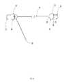
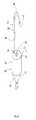
- FIGS. 1 a and 1 bshow an embodiment of the apparatus comprising a pair of tissue connectors connected by a cord where one of the tissue connectors employs a releasable one-way cord lock that enables adjusting the length of the portion of the cord extending between the pair of tissue connectors.
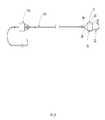
- FIGS. 2 a and 2 bshow further embodiments of the apparatus similar to that of FIGS. 1 a and 1 b.
- FIG. 3is a perspective view of one of the tissue connectors.
- FIG. 4is a plan view of the tissue connector of FIG. 3 .
- FIGS. 5 a and 5 billustrate the assembly of the tissue connector of FIG. 3 .
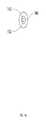
- FIG. 6is a perspective view of a further embodiment of a tissue connector.
- FIG. 7is a plan view of the tissue connector of FIG. 6 .
- FIGS. 8 a and 8 billustrate the assembly of the tissue connector of FIG. 6 .
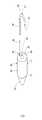
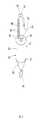
- FIG. 9is a perspective view of a further embodiment of a tissue connector.
- FIG. 10is a side view of the tissue connector of FIG. 9 .
- FIG. 11is cross-section view of the tissue connector of FIG. 9 .
- FIG. 12is a perspective view of the disassembled component parts of the tissue connector of FIG. 9 .
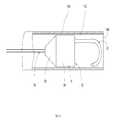
- FIG. 13is a cross-section view of the delivery and removal tube of the apparatus.
- FIG. 14is an end view of the proximal end of the delivery and removal tube.
- FIG. 15is a side view of the delivery rod of the apparatus.
- FIG. 16is a partial sectioned view of the apparatus illustrating the method of removing a tissue connector of the apparatus from an abdominal cavity using the delivery and removal tube of the apparatus.
- FIG. 17is a partial sectioned view of the apparatus further illustrating the method of removing a tissue connector of the apparatus from an abdominal cavity using the delivery and removal tube of the apparatus.
- FIGS. 1A and 1Bshow an embodiment of the tissue connector apparatus of the invention that is constructed to facilitate the delivery of the tissue connectors through a cannula or other type of tubular delivery device to a surgical site of a body for use in a laparoscopic surgery or other type of surgical procedure, and facilitate the removal of the tissue connectors of the apparatus following completion of the procedure.
- the component parts of the apparatusare dimensioned to be inserted through an incision or through a cannula, trocar, endoscope or other type of tubular delivery device extending into the body to position the apparatus at a surgery site. All of the component parts of the apparatus to be described are constructed of biocompatible materials.
- the first embodiment of the apparatusis shown in FIGS. 1 a and 1 b .
- the embodiment shownis basically comprised of a first tissue connector 12 , a second tissue connector 14 and a length of cord 16 extending between and connecting the two tissue connectors.
- the cordcould be a suture, IV tubing or other equivalent types of cord and could be one piece or several pieces connected together.
- the first tissue connector 12is comprised of a base 18 and a hook 22 .
- the base 18for the most part is a solid single piece of material having a side exterior surface that extends completely around the base.
- the side surface 24is cylindrical.
- the cylindrical surface 24has a center axis 26 that defines mutually perpendicular axial and radial directions relative to the base.
- the basealso has a proximal end surface 28 at one axial end of the base and a distal end surface 30 at an opposite axial end of the base.
- the proximal end surface 28is chamfered or tapers as it extends axially away from the base side surface 24 .
- the proximal end surface 28has a conical configuration with a circular peripheral edge 32 defined by the intersection of the proximal end surface with the cylindrical base side surface 24 .
- the proximal end surface 28tapers as it extends axially from the base side surface 24 to an apex end 34 of the proximal end surface.
- the base distal end surface 30is substantially flat.
- the distal end surface 30has a circular peripheral edge 36 defined by the intersection of the distal end surface with the cylindrical base side surface 24 .
- a hook hole 38is formed in the base distal end surface 30 .
- the hook hole 38is spaced radially inwardly from the distal end surface peripheral edge 36 and radially from the center axis 26 .
- the hook holeextends axially into the base a short distance from the distal end surface 30 and does not extend entirely through the base.
- a center hole 42is also formed in the base at the center of the base distal end surface 30 .
- the center hole 42extends axially through the base and emerges at the apex 34 of the base proximal end surface 28 .
- the center hole 42has a slightly larger interior diameter dimension adjacent the base distal end surface 30 than the interior diameter dimension of the hole 42 adjacent the apex 34 of the base proximal end surface 28 .
- the hook 22has a straight shank portion 44 extending from a proximal end 46 of the hook.
- the hook shank portion adjacent the hook proximal end 46is dimensioned with a cylindrical exterior surface that fits tightly into the hook hole 38 in the base distal end surface 30 .
- the hook shank portion 34is secured stationary to the base by laser welding or other equivalent means.
- the hook 22is secured to the base distal end surface 32 with the hook shank portion 34 extending axially from the distal end surface 32 substantially parallel with the center axis 26 , but radially spaced from the center axis.
- the hook shank portion 44 extending from the distal end surface 30has a square or other similar cross-section configuration to facilitate grasping the hook with a surgical grasper and preventing the hook shank from rotating in the grasper.
- the shank portion 44extends axially from the base distal end surface 30 to a bent portion 48 of the hook that extends radially across the distal end surface 30 , through the base center axis 26 and to a distal end tip 52 of the hook.
- the distal end tip 52 and shank portion 44 of the hookare each radially spaced on opposite sides of the base center axis.
- the shank portion 44 and end tip 52are both spaced a radial distance dimension on opposite sides of the center axis 26 that is smaller than the base radius dimension, whereby the hook bent portion and tip do not project radially beyond the cylindrical side surface of the base.
- the hook 22is shown as the part of the tissue connector 12 that is removably attachable to body tissue, other equivalent devices that do not project radially beyond the side surface of the base could be used.
- the cord 16has a flexible length with opposite first 54 and second 56 ends.
- the cord first end 54passes through the center hole 42 of the first tissue connector 12 from the proximal end surface 28 to the distal end surface 30 .
- a knot 58is tied in the cord first end 54 .
- a medical grade glue, for example cyanoacrylateis applied to the knot.
- the cordis pulled from the base proximal end surface 28 to pull the knot 58 into the center hole 42 in the base distal end surface 30 .
- the knot 56is too large to pass though the smaller portion of the center hole 42 that emerges from the apex 34 of the proximal end surface 28 .
- the cord first end 54is secured to the first tissue connector 12 with the cord extending from the base proximal end surface 28 of the tissue connector.
- FIGS. 6, 7, 8 a and 8 bshow an alternate embodiment of the first tissue connector where a post 62 of an eyelet ring 64 is inserted through the base center hole 42 from the base proximal end surface 28 .
- the post 62is secured to the base by laser welding the end of the post 62 in the center hole at the base distal end surface 32 .
- the eyelet ring 64could be secured to the base by other equivalent means.
- the first end 54 of the cord 16is then secured to the eyelet 64 by a knot being tied in the cord around the eyelet ring 64 and the knot being secured by a medical grade glue.
- FIGS. 9, 10, 11 and 12Details of the construction of the second tissue connector 14 are shown in FIGS. 9, 10, 11 and 12 .
- the second tissue connector 14is also basically comprised of a base 68 and a hook 72 projecting from the base.
- the base 68has a side surface 74 that extends completely around the base.
- the in embodiment shown in the drawing figures the side surface 74is cylindrical and has a center axis 76 that defines mutually perpendicular axial and radial directions relative to the base 68 .
- the base 68also has a proximal end surface 78 at one axial end of the base and a distal end surface 80 at the opposite axial end of the base.
- the base proximal end surface 78is chamfered or tapers as it extends axially away from the cylindrical side surface 74 .
- the base proximal end surface 78has a conical configuration with a circular peripheral edge 82 defined by the intersection of the proximal end surface 78 with the cylindrical base side surface 74 .
- the proximal end surface 78tapers as it extends from the cylindrical side surface 74 to an apex 84 on the proximal end surface.
- a hole 86passes through the center of the apex 84 of the proximal end surface 78 to an interior bore of the base that is described later.
- the base distal end surface 80is substantially flat.
- the distal end surface 80has a circular peripheral edge 88 defined by the intersection of the distal end surface 80 and the cylindrical base side surface 74 .
- a hook hole 92is formed in the base distal end surface 80 .
- the hook hole 92is spaced radially inwardly from the distal end surface peripheral edge 88 and radially from the center axis 76 .
- the hook hole 92extends axially into the base a short distance from the distal end surface 80 and does not extend entirely through the base.
- the hook 72 of the second tissue connector 14has substantially the same construction as the hook 22 of the first tissue connector 12 .
- the hook 72has a straight shank portion 94 extending from a proximal end 96 of the hook. Adjacent the proximal end 96 the hook shank portion has a cylindrical configuration dimensioned to fit tightly into the hook hole 88 on the distal end surface 80 .
- the hook shank portion 94is secured to the base distal end surface 80 by laser welding or other equivalent means.
- the hook shank portion 94extends axially from the base distal end surface 80 substantially parallel with the base center axis 76 but spaced radially from the center axis.
- the shank portion 94 extending from the distal end surface 80has a square or other similar cross-section configuration that facilitates grasping the shank portion with surgical graspers and preventing rotation of the shank portion in the graspers.
- the hook shank portion 94extends axially from the base to a bent portion 98 of the hook that extends radially over the base distal end surface 80 and through the base center axis 76 .
- the hook bent portion 98extends from the shank portion 94 to a distal end tip 100 of the hook.
- the hook distal end tip 100 and shank portion 94are both spaced a radial distance dimension on opposite sides of the center axis 76 that is smaller than the base radius dimension, whereby the hook bent portion and the distal end tip 100 do not project radially beyond the cylindrical side surface 74 of the base.
- the hook 72is shown as the part of the tissue connector that is removably attachable to body tissue, other equivalent devices that do not project radially beyond the side surface of the base could be used.
- both tissue connectors 12 , 14are described as having chamfered or tapered surfaces 28 , 78 , it is not necessary that both have tapered surfaces for the intended functioning of the apparatus.
- the second tissue connector 14is constructed with a releasable one-way cord lock that enables the length of the portion of the cord 16 extending between the two tissue connectors 12 , 14 to be adjusted.
- the second tissue connector base 68has a tubular configuration with a cylindrical housing wall having the base cylindrical side surface 74 on its exterior, and a hollow interior bore 102 extending through the length of the housing wall interior.
- a disk shaped cap 104is secured to a distal end of the base housing wall by laser welding or other equivalent means.
- the disk-shaped cap 104defines the distal and surface 80 of the base.
- a rod or pin 106is secured to the base 68 in the base interior bore 102 .
- the rod 106extends radially across the base interior bore 102 adjacent the proximal end surface 78 of the base. Opposite ends of the rod 106 are secured to the interior surface of the base cylindrical housing.
- the cord 6is secured to the second tissue connector 14 inside the base interior bore 102 .
- the second end 56 of the cord 16extends through the center hole 86 in the apex of the base proximal end surface 78 and into the hollow interior bore 102 of the base.
- An intermediate portion of the cord 112is wrapped around the rod 106 in the base interior, thereby attaching the cord 16 to the second tissue connector 14 .
- the intermediate portion of the cord 112is wrapped around the rod 106 by being tied in a knot around the rod.
- the preferred knot 112is a Blunter hitch knot.
- a first portion 114 of the cord lengthextends from the intermediate portion 112 though the base center hole 86 .
- the cord first portion 114extends from the proximal end surface 78 of the base to the cord first end 54 attached to the first tissue connector 12 .
- a second portion of the cord length 116extends from the cord intermediate portion 112 through a side hole 118 in the base cylindrical side surface 74 and the proximal end surface 78 .
- the side hole 118is provided to separate the cord first portion 114 and the cord second portion 116 to prevent tangling.
- the side hole 118also allows for a greater angle that the cord second portion 116 can be pulled from the connector.
- the second portion of the cord 116extends from second tissue connector 14 to a second, free end 122 of a cord.
- the releasable one-way cord lockis comprised of a pair slots 124 that are formed in radially opposite sides of the cylindrical side wall of the base 68 . As seen in the drawing figures, the slots 124 extend axially along a portion of the cylindrical wall of the base 68 and are positioned radially to one side of the base center axis 76 .
- a lock pin 126is positioned in the slots 124 and extends from one slot 124 across the interior bore of the base 68 to the other slot. The lock pin 126 slides axially along the slots 124 .
- An actuator 128is mounted on the base cylindrical side surface 74 and is connected to the lock pin 126 inside the base.
- the actuator 128is formed as cylindrical sleeve that surrounds the base cylindrical side surface 74 .
- the actuator 128is mounted on the cylindrical side surface 74 of the base 68 for axially reciprocating movements between first and second positions of the actuator 128 relative to the base 68 .
- the opposite ends of the lock pin 126project beyond the slots 124 in the base cylindrical side surface 74 and are secured in opposite sides of the actuator 128 . Moving the actuator 128 to its first position shown in FIG. 11 causes the lock pin 126 to engage against the cord intermediate portion 112 that is wrapped around the rod 106 .
- FIG. 11Moving the actuator 128 to its first position shown in FIG. 11 causes the lock pin 126 to engage against the cord intermediate portion 112 that is wrapped around the rod 106 .
- the pin 126prevents the knot 112 from rotating counterclockwise around the rod 106 when the knot 112 is in a 3 o'clock position, or to the right of the rod as shown in FIG. 11 and the cord first portion 114 is pulled.
- the engagement of the lock pin 126 against the cord intermediate portion or knot 112locks the cord and prevents the first portion of the cord length 114 from being pulled from the proximal end surface 78 of the second tissue connector 14 .
- the cord second portion 116can be pulled from the second tissue connector 14 to shorten the length of the cord first portion 114 , but the cord first portion 114 cannot be pulled from the connector.
- a biasing device 132urges the lock pin 126 to its first position shown in FIG. 11 .
- the biasing device 132is coiled spring. Other equivalent types of biasing devices could be employed.
- the slot 124 and the pin 126are off center relative to the base cylindrical side surface 74 to facilitate the knot 112 pushing the pin 126 upward against the bias of the spring 132 when the cord second portion 116 is pulled and the knot 112 moves clockwise from the 6 o'clock position to the 3 o'clock position relative to the rod 106 .
- Tissue connectors having one way cord lockssuch as that described above are disclosed in the currently pending international patent application No. PCT/US2011/01494 which is assigned to the assignee of this invention and is incorporated herein by reference.
- FIG. 2 ashows a further embodiment of the apparatus of the invention comprising the first tissue connector 12 and the second tissue connector 14 connected by the length of cord 16 .
- the first end of the length of cord 16is connected to the first tissue connector 12 having the eyelet ring 64 that was described earlier.
- a second length of cord 134connects a third tissue connector 136 to the first tissue connector 12 .
- the construction of the third tissue connector 136is substantially the same as that of the second tissue connector 14 described earlier.
- at least two of the three tissue connectorswould require tapered proximal end surfaces in order for the apparatus to function as intending in removing the apparatus from a surgical site as described be low.
- FIG. 2Bshows a still further embodiment of the apparatus where the tissue connector hook 72 or other equivalent device is not directly connected to the base 68 of the second tissue connector 14 , but is connected by a further length of suture 138 .
- the apparatus of the inventionalso comprises a tissue connector deliver and removal tube 142 shown in FIGS. 13 and 14 , and a delivery rod 144 shown in FIG. 15 .
- the tube 142has a straight length with opposite proximal 146 and distal 148 ends.
- An interior bore having a smooth cylindrical interior surface 152extends through the length of the tube.
- the cylindrical interior surface 152has an interior diameter dimension that is just slightly larger than the exterior diameter dimension of the first tissue connector base cylindrical side surface 24 and the second tissue connector base cylindrical side surface 74 . This enables the tissue connectors 12 , 14 to easily slide through the interior bore of the tube when delivering the tissue connectors through the tube, or removing the tissue connectors through the tube.
- the delivery rod 144has a straight length that is dimensioned to be inserted into the tube proximal end 146 to push the tissue connectors 12 , 14 and the connecting cord 16 through the tube interior bore to deliver the tissue connectors and the connecting cord from the tube distal end 142 and to a surgical site in a body.
- the tapered configuration of the base proximal end surface 28 of the first tissue connector 12 and the tapered configuration of the base proximal end surface 78 of the second tissue connector 14enables the tissue connectors to be easily pulled into the interior bore of the tube 42 at the tube distal end 148 .
- the tube distal end 142is positioned in the area by inserting the distal end through a cannula or through an incision to position the tube distal end 148 at the surgical site.
- An instrumentfor example a surgical grasper is then inserted through the tube 142 until it emerges from the tube distal end 148 .
- the surgical grasperthen grasps the second tissue connector 14 at the hook 72 .
- the surgical grasperis then removed through the tube 142 moving the second connector 14 hook first into the tube distal end and pulling the cord into the tube distal end 142 .
- the cord 16is then continued to be pulled through the tube until the tapered configuration of the base proximal end surface 28 of the first tissue connector 12 is pulled into the tube distal end 148 .
- the tapered configuration of the proximal end surface 28centers the base cylindrical side surface 24 of the first tissue connector 12 relative the tube interior bore as the tapered proximal end surface is pulled into the tube interior bore.
- the hook 22 projecting from the base distal end surface 30is prevented from snagging or catching the distal end 148 of the tube 142 as the first tissue connector is pulled into an through the tube.
- the apparatus of the invention and its method of usefacilitate the delivery of surgical tissue connectors to a laparoscopic surgical site and facilitate the removal of the surgical connectors from the surgical site.
Landscapes
- Health & Medical Sciences (AREA)
- Life Sciences & Earth Sciences (AREA)
- Surgery (AREA)
- Heart & Thoracic Surgery (AREA)
- Engineering & Computer Science (AREA)
- Biomedical Technology (AREA)
- Nuclear Medicine, Radiotherapy & Molecular Imaging (AREA)
- Medical Informatics (AREA)
- Molecular Biology (AREA)
- Animal Behavior & Ethology (AREA)
- General Health & Medical Sciences (AREA)
- Public Health (AREA)
- Veterinary Medicine (AREA)
- Rheumatology (AREA)
- Surgical Instruments (AREA)
Abstract
Description
Claims (15)
Priority Applications (1)
| Application Number | Priority Date | Filing Date | Title |
|---|---|---|---|
| US14/411,243US9855044B2 (en) | 2012-06-29 | 2013-06-26 | Apparatus and method for delivering surgical tissue connectors into an abdominal cavity and removing the surgical tissue connectors from the abdominal cavity |
Applications Claiming Priority (3)
| Application Number | Priority Date | Filing Date | Title |
|---|---|---|---|
| US201261666380P | 2012-06-29 | 2012-06-29 | |
| US14/411,243US9855044B2 (en) | 2012-06-29 | 2013-06-26 | Apparatus and method for delivering surgical tissue connectors into an abdominal cavity and removing the surgical tissue connectors from the abdominal cavity |
| PCT/US2013/047862WO2014004654A1 (en) | 2012-06-29 | 2013-06-26 | Apparatus and method for delivering surgical tissue connectors into an abdominal cavity and removing the surgical tissue connectors from the abdominal cavity |
Related Parent Applications (1)
| Application Number | Title | Priority Date | Filing Date |
|---|---|---|---|
| PCT/US2013/047862A-371-Of-InternationalWO2014004654A1 (en) | 2012-06-29 | 2013-06-26 | Apparatus and method for delivering surgical tissue connectors into an abdominal cavity and removing the surgical tissue connectors from the abdominal cavity |
Related Child Applications (1)
| Application Number | Title | Priority Date | Filing Date |
|---|---|---|---|
| US15/860,416ContinuationUS10743878B2 (en) | 2012-06-29 | 2018-01-02 | Apparatus and method for delivering surgical tissue connectors into an abdominal cavity and removing the surgical tissue connectors from the abdominal cavity |
Publications (2)
| Publication Number | Publication Date |
|---|---|
| US20150201934A1 US20150201934A1 (en) | 2015-07-23 |
| US9855044B2true US9855044B2 (en) | 2018-01-02 |
Family
ID=49783830
Family Applications (3)
| Application Number | Title | Priority Date | Filing Date |
|---|---|---|---|
| US14/411,243Active2035-01-07US9855044B2 (en) | 2012-06-29 | 2013-06-26 | Apparatus and method for delivering surgical tissue connectors into an abdominal cavity and removing the surgical tissue connectors from the abdominal cavity |
| US15/860,416Expired - Fee RelatedUS10743878B2 (en) | 2012-06-29 | 2018-01-02 | Apparatus and method for delivering surgical tissue connectors into an abdominal cavity and removing the surgical tissue connectors from the abdominal cavity |
| US16/996,447Active2034-12-06US11786249B2 (en) | 2012-06-29 | 2020-08-18 | Apparatus and method for delivering surgical tissue connectors into an abdominal cavity and removing the surgical tissue connectors from the abdominal cavity |
Family Applications After (2)
| Application Number | Title | Priority Date | Filing Date |
|---|---|---|---|
| US15/860,416Expired - Fee RelatedUS10743878B2 (en) | 2012-06-29 | 2018-01-02 | Apparatus and method for delivering surgical tissue connectors into an abdominal cavity and removing the surgical tissue connectors from the abdominal cavity |
| US16/996,447Active2034-12-06US11786249B2 (en) | 2012-06-29 | 2020-08-18 | Apparatus and method for delivering surgical tissue connectors into an abdominal cavity and removing the surgical tissue connectors from the abdominal cavity |
Country Status (8)
| Country | Link |
|---|---|
| US (3) | US9855044B2 (en) |
| EP (1) | EP2866679B1 (en) |
| JP (3) | JP6148337B2 (en) |
| CN (1) | CN104540456B (en) |
| AU (2) | AU2013280369B2 (en) |
| CA (1) | CA2877865C (en) |
| IN (1) | IN2015DN00690A (en) |
| WO (1) | WO2014004654A1 (en) |
Cited By (1)
| Publication number | Priority date | Publication date | Assignee | Title |
|---|---|---|---|---|
| US20210178120A1 (en)* | 2018-05-01 | 2021-06-17 | Boston Scientific Scimed, Inc. | Tissue retraction device and delivery system |
Families Citing this family (5)
| Publication number | Priority date | Publication date | Assignee | Title |
|---|---|---|---|---|
| AU2013280369B2 (en)* | 2012-06-29 | 2017-03-09 | FreeHold Surgical, LLC | Apparatus and method for delivering surgical tissue connectors into an abdominal cavity and removing the surgical tissue connectors from the abdominal cavity |
| JP6682763B2 (en)* | 2015-02-03 | 2020-04-15 | 日本ゼオン株式会社 | Endoscope treatment tool |
| CN105962978A (en)* | 2016-04-19 | 2016-09-28 | 常州优复瑞医疗器械有限公司 | Human body surgery intracavity exposure support device |
| EP3451938B1 (en)* | 2016-05-03 | 2022-02-23 | Livac IP Co Pty Ltd | Hook and fenestration retractor |
| EP3968866A1 (en)* | 2019-05-16 | 2022-03-23 | Boston Scientific Scimed, Inc. | Tissue traction bands and methods for tissue traction |
Citations (34)
| Publication number | Priority date | Publication date | Assignee | Title |
|---|---|---|---|---|
| US302509A (en) | 1884-07-22 | Max matjthnee | ||
| US3695271A (en) | 1970-06-03 | 1972-10-03 | Technalytics Inc | Retention suture bridge |
| US5193955A (en) | 1991-12-06 | 1993-03-16 | Chou An Chuan | Binding device for cargos |
| US5362294A (en) | 1992-09-25 | 1994-11-08 | Seitzinger Michael R | Sling for positioning internal organ during laparoscopic surgery and method of use |
| US5383904A (en) | 1992-10-13 | 1995-01-24 | United States Surgical Corporation | Stiffened surgical device |
| US5415666A (en) | 1992-03-23 | 1995-05-16 | Advanced Surgical, Inc. | Tethered clamp retractor |
| US5582577A (en) | 1995-02-13 | 1996-12-10 | Vance Products Incorporated | Surgical retractor including central elastic member |
| WO1998007374A1 (en) | 1996-08-21 | 1998-02-26 | Hayhurst John O | Suturing system |
| US6042534A (en) | 1997-02-13 | 2000-03-28 | Scimed Life Systems, Inc. | Stabilization sling for use in minimally invasive pelvic surgery |
| US20010041916A1 (en) | 2000-05-03 | 2001-11-15 | Bonutti Peter M. | Method of securing body tissue |
| WO2002030293A1 (en) | 2000-10-12 | 2002-04-18 | Gyne Ideas Limited | Apparatus and method for treating female urinary incontinence |
| WO2003096907A1 (en) | 2002-05-17 | 2003-11-27 | Tyco Healthcare Group, Lp | Endoscopic organ retraction system and method of using the same |
| US20040225305A1 (en) | 1999-06-25 | 2004-11-11 | Usgi Medical | Apparatus and methods for forming and securing gastrointestinal tissue folds |
| US20050043580A1 (en) | 2003-08-22 | 2005-02-24 | American Medical Systems | Surgical article and methods for treating female urinary incontinence |
| EP1568326A1 (en) | 2004-02-24 | 2005-08-31 | DePuy Mitek, Inc. | Methods and devices for repairing tissue |
| US20050216040A1 (en) | 2004-03-23 | 2005-09-29 | Michael Gertner | Devices and methods to treat a patient |
| US20050250980A1 (en) | 2004-05-07 | 2005-11-10 | Usgi Medical Corp. | Methods for performing gastroplasty |
| US20060106423A1 (en) | 2004-09-28 | 2006-05-18 | Thomas Weisel | Suture anchor |
| US20070250116A1 (en) | 2006-04-25 | 2007-10-25 | Board Of Regents, The University Of Texas System | Tissue Approximator and Retractor Assistive Device |
| WO2007149593A2 (en) | 2006-06-22 | 2007-12-27 | Ams Research Corporation | Adjustable tension incontinence sling assemblies |
| US20080021485A1 (en) | 2005-05-20 | 2008-01-24 | Neotract, Inc. | Apparatus and method for manipulating or retracting tissue and anatomical structure |
| JP2008142516A (en) | 2006-11-13 | 2008-06-26 | Nobuyuki Sakurazawa | Mucosa pulling tool |
| US20090018552A1 (en) | 2002-12-11 | 2009-01-15 | Usgi Medical, Inc. | Apparatus and methods for forming and securing gastrointestinal tissue folds |
| WO2009064866A1 (en) | 2007-11-13 | 2009-05-22 | C. R. Bard, Inc. | Adjustable tissue support member |
| WO2009140298A2 (en) | 2008-05-12 | 2009-11-19 | Wright John T M | Device and method for the surgical treatment of ischemic mitral regurgitation |
| US20100081864A1 (en) | 2008-09-30 | 2010-04-01 | Ethicon Endo-Surgery, Inc. | Methods and devices for performing gastrectomies and gastroplasties |
| WO2010099327A1 (en) | 2009-02-25 | 2010-09-02 | Scott J Stephen | Apparatus and method for intra-abdominally moving a first internal organ to a position away from a second internal organ and then holding the first internal organ in the position without manual input |
| US20100256678A1 (en) | 2009-04-03 | 2010-10-07 | Wilson-Cook Medical Inc. | Tissue anchors and medical devices for rapid deployment of tissue anchors |
| US20100292540A1 (en) | 2009-05-12 | 2010-11-18 | Hess Christopher J | Surgical retractor and method |
| US20100292732A1 (en) | 2009-05-12 | 2010-11-18 | Foundry Newco Xi, Inc. | Suture anchors with one-way cinching mechanisms |
| US20110112357A1 (en) | 2006-06-16 | 2011-05-12 | Ams Research Corporation | Surgical implants, tools, and methods for treating pelvic conditions |
| US20110172682A1 (en) | 2010-01-11 | 2011-07-14 | Anulex Technologies , Inc. | Intervertebral disc annulus repair system and bone anchor delivery tool |
| US20120078298A1 (en) | 2005-02-07 | 2012-03-29 | Sklar Joseph H | Knotless suture anchor for securing soft tissue to bone |
| WO2013028145A1 (en) | 2011-08-25 | 2013-02-28 | Scott Stephen J | Apparatus and method for intra-abdominally moving a first internal organ to a position away from a second internal organ and then holding the first internal organ in the position without manual input |
Family Cites Families (6)
| Publication number | Priority date | Publication date | Assignee | Title |
|---|---|---|---|---|
| US5507754A (en)* | 1993-08-20 | 1996-04-16 | United States Surgical Corporation | Apparatus and method for applying and adjusting an anchoring device |
| US7862584B2 (en)* | 2003-05-07 | 2011-01-04 | Anpa Medical, Inc. | Suture lock |
| US20050251208A1 (en)* | 2004-05-07 | 2005-11-10 | Usgi Medical Inc. | Linear anchors for anchoring to tissue |
| EP2032044A2 (en)* | 2006-05-25 | 2009-03-11 | Mitralign, Inc. | Lockers for surgical tensioning members and methods of using the same to secure surgical tensioning members |
| JP4696087B2 (en)* | 2006-09-12 | 2011-06-08 | 信行 櫻澤 | Organ traction tool |
| AU2013280369B2 (en)* | 2012-06-29 | 2017-03-09 | FreeHold Surgical, LLC | Apparatus and method for delivering surgical tissue connectors into an abdominal cavity and removing the surgical tissue connectors from the abdominal cavity |
- 2013
- 2013-06-26AUAU2013280369Apatent/AU2013280369B2/ennot_activeCeased
- 2013-06-26EPEP13809773.8Apatent/EP2866679B1/ennot_activeNot-in-force
- 2013-06-26CNCN201380042514.7Apatent/CN104540456B/ennot_activeExpired - Fee Related
- 2013-06-26JPJP2015520432Apatent/JP6148337B2/ennot_activeExpired - Fee Related
- 2013-06-26CACA2877865Apatent/CA2877865C/enactiveActive
- 2013-06-26WOPCT/US2013/047862patent/WO2014004654A1/enactiveApplication Filing
- 2013-06-26USUS14/411,243patent/US9855044B2/enactiveActive
- 2013-06-26ININ690DEN2015patent/IN2015DN00690A/enunknown
- 2017
- 2017-05-22JPJP2017101069Apatent/JP6328302B2/ennot_activeExpired - Fee Related
- 2017-05-24AUAU2017203467Apatent/AU2017203467B2/ennot_activeCeased
- 2018
- 2018-01-02USUS15/860,416patent/US10743878B2/ennot_activeExpired - Fee Related
- 2018-04-18JPJP2018080213Apatent/JP6553243B2/ennot_activeExpired - Fee Related
- 2020
- 2020-08-18USUS16/996,447patent/US11786249B2/enactiveActive
Patent Citations (40)
| Publication number | Priority date | Publication date | Assignee | Title |
|---|---|---|---|---|
| US302509A (en) | 1884-07-22 | Max matjthnee | ||
| US3695271A (en) | 1970-06-03 | 1972-10-03 | Technalytics Inc | Retention suture bridge |
| US5193955A (en) | 1991-12-06 | 1993-03-16 | Chou An Chuan | Binding device for cargos |
| US5415666A (en) | 1992-03-23 | 1995-05-16 | Advanced Surgical, Inc. | Tethered clamp retractor |
| US5362294A (en) | 1992-09-25 | 1994-11-08 | Seitzinger Michael R | Sling for positioning internal organ during laparoscopic surgery and method of use |
| US5383904A (en) | 1992-10-13 | 1995-01-24 | United States Surgical Corporation | Stiffened surgical device |
| US5582577A (en) | 1995-02-13 | 1996-12-10 | Vance Products Incorporated | Surgical retractor including central elastic member |
| WO1998007374A1 (en) | 1996-08-21 | 1998-02-26 | Hayhurst John O | Suturing system |
| US6042534A (en) | 1997-02-13 | 2000-03-28 | Scimed Life Systems, Inc. | Stabilization sling for use in minimally invasive pelvic surgery |
| US20040225305A1 (en) | 1999-06-25 | 2004-11-11 | Usgi Medical | Apparatus and methods for forming and securing gastrointestinal tissue folds |
| US20010041916A1 (en) | 2000-05-03 | 2001-11-15 | Bonutti Peter M. | Method of securing body tissue |
| WO2002030293A1 (en) | 2000-10-12 | 2002-04-18 | Gyne Ideas Limited | Apparatus and method for treating female urinary incontinence |
| US20050203344A1 (en) | 2002-03-02 | 2005-09-15 | Tyco Healthcare Group Lp | Endoscopic organ retraction system and method of using the same |
| WO2003096907A1 (en) | 2002-05-17 | 2003-11-27 | Tyco Healthcare Group, Lp | Endoscopic organ retraction system and method of using the same |
| US20090018552A1 (en) | 2002-12-11 | 2009-01-15 | Usgi Medical, Inc. | Apparatus and methods for forming and securing gastrointestinal tissue folds |
| US20050043580A1 (en) | 2003-08-22 | 2005-02-24 | American Medical Systems | Surgical article and methods for treating female urinary incontinence |
| EP1568326A1 (en) | 2004-02-24 | 2005-08-31 | DePuy Mitek, Inc. | Methods and devices for repairing tissue |
| US20050216040A1 (en) | 2004-03-23 | 2005-09-29 | Michael Gertner | Devices and methods to treat a patient |
| US20050250980A1 (en) | 2004-05-07 | 2005-11-10 | Usgi Medical Corp. | Methods for performing gastroplasty |
| US20060106423A1 (en) | 2004-09-28 | 2006-05-18 | Thomas Weisel | Suture anchor |
| US20120078298A1 (en) | 2005-02-07 | 2012-03-29 | Sklar Joseph H | Knotless suture anchor for securing soft tissue to bone |
| US20080021485A1 (en) | 2005-05-20 | 2008-01-24 | Neotract, Inc. | Apparatus and method for manipulating or retracting tissue and anatomical structure |
| US20070250116A1 (en) | 2006-04-25 | 2007-10-25 | Board Of Regents, The University Of Texas System | Tissue Approximator and Retractor Assistive Device |
| US20110112357A1 (en) | 2006-06-16 | 2011-05-12 | Ams Research Corporation | Surgical implants, tools, and methods for treating pelvic conditions |
| WO2007149593A2 (en) | 2006-06-22 | 2007-12-27 | Ams Research Corporation | Adjustable tension incontinence sling assemblies |
| US20100261950A1 (en) | 2006-06-22 | 2010-10-14 | Ams Research Corporation | Adjustable Tension Incontinence Sling Assemblies |
| JP2008142516A (en) | 2006-11-13 | 2008-06-26 | Nobuyuki Sakurazawa | Mucosa pulling tool |
| US20090137862A1 (en) | 2007-11-13 | 2009-05-28 | C. R. Bard, Inc. | Adjustable tissue support member |
| WO2009064866A1 (en) | 2007-11-13 | 2009-05-22 | C. R. Bard, Inc. | Adjustable tissue support member |
| WO2009140298A2 (en) | 2008-05-12 | 2009-11-19 | Wright John T M | Device and method for the surgical treatment of ischemic mitral regurgitation |
| US20100081864A1 (en) | 2008-09-30 | 2010-04-01 | Ethicon Endo-Surgery, Inc. | Methods and devices for performing gastrectomies and gastroplasties |
| US20120116153A1 (en) | 2009-02-25 | 2012-05-10 | Mis Solutions, Inc. | Apparatus and method for intra-abdominally moving a first internal organ to a position away from a second internal organ and then holding the first internal organ in the position without manual input |
| WO2010099327A1 (en) | 2009-02-25 | 2010-09-02 | Scott J Stephen | Apparatus and method for intra-abdominally moving a first internal organ to a position away from a second internal organ and then holding the first internal organ in the position without manual input |
| US8888679B2 (en) | 2009-02-25 | 2014-11-18 | Freehold Surgical, Inc. | Apparatus and method for intra-abdominally moving a first internal organ to a position away from a second internal organ and the holding the first internal organ in the position without manual input |
| US8251889B2 (en) | 2009-02-25 | 2012-08-28 | Mis Solutions, Inc. | Apparatus and method for intra-abdominally moving a first internal organ to a position away from a second internal organ and then holding the first internal organ in the position without manual input |
| US20100256678A1 (en) | 2009-04-03 | 2010-10-07 | Wilson-Cook Medical Inc. | Tissue anchors and medical devices for rapid deployment of tissue anchors |
| US20100292540A1 (en) | 2009-05-12 | 2010-11-18 | Hess Christopher J | Surgical retractor and method |
| US20100292732A1 (en) | 2009-05-12 | 2010-11-18 | Foundry Newco Xi, Inc. | Suture anchors with one-way cinching mechanisms |
| US20110172682A1 (en) | 2010-01-11 | 2011-07-14 | Anulex Technologies , Inc. | Intervertebral disc annulus repair system and bone anchor delivery tool |
| WO2013028145A1 (en) | 2011-08-25 | 2013-02-28 | Scott Stephen J | Apparatus and method for intra-abdominally moving a first internal organ to a position away from a second internal organ and then holding the first internal organ in the position without manual input |
Non-Patent Citations (3)
| Title |
|---|
| European Search Report and European Search Opinion dated Apr. 14, 2015 from European Application 11871286.6. |
| European Search Report dated Apr. 26, 2016 from European Application 13809773.8. |
| Sakaguchi, et. al., New technique for the retraction of the liver in laparoscopic gastrectomy, 22 Surgical Endoscopy 2532 (2008). |
Cited By (2)
| Publication number | Priority date | Publication date | Assignee | Title |
|---|---|---|---|---|
| US20210178120A1 (en)* | 2018-05-01 | 2021-06-17 | Boston Scientific Scimed, Inc. | Tissue retraction device and delivery system |
| US12208219B2 (en)* | 2018-05-01 | 2025-01-28 | Boston Scientific Scimed, Inc. | Tissue retraction device and delivery system |
Also Published As
| Publication number | Publication date |
|---|---|
| EP2866679A1 (en) | 2015-05-06 |
| CN104540456A (en) | 2015-04-22 |
| AU2017203467B2 (en) | 2019-12-05 |
| EP2866679A4 (en) | 2016-05-25 |
| US20180116666A1 (en) | 2018-05-03 |
| CA2877865C (en) | 2020-09-01 |
| US20200375599A1 (en) | 2020-12-03 |
| JP6553243B2 (en) | 2019-07-31 |
| JP2015522343A (en) | 2015-08-06 |
| US11786249B2 (en) | 2023-10-17 |
| JP6148337B2 (en) | 2017-06-14 |
| IN2015DN00690A (en) | 2015-06-26 |
| EP2866679B1 (en) | 2018-11-07 |
| JP2018134460A (en) | 2018-08-30 |
| US20150201934A1 (en) | 2015-07-23 |
| CN104540456B (en) | 2019-01-08 |
| CA2877865A1 (en) | 2014-01-03 |
| US10743878B2 (en) | 2020-08-18 |
| WO2014004654A1 (en) | 2014-01-03 |
| AU2013280369B2 (en) | 2017-03-09 |
| JP2017176854A (en) | 2017-10-05 |
| JP6328302B2 (en) | 2018-05-23 |
| AU2017203467A1 (en) | 2017-06-08 |
| AU2013280369A1 (en) | 2015-02-19 |
Similar Documents
| Publication | Publication Date | Title |
|---|---|---|
| US11786249B2 (en) | Apparatus and method for delivering surgical tissue connectors into an abdominal cavity and removing the surgical tissue connectors from the abdominal cavity | |
| AU2017254810B2 (en) | Endoscopic Suturing System | |
| EP3493750B1 (en) | Systems, devices, and related methods for retracting tissue | |
| US11083364B2 (en) | Endoscopic tissue grasping systems and methods | |
| US8287556B2 (en) | Endoscopic suturing system | |
| EP3150130B1 (en) | Apparatus for guiding a suture thread | |
| JP2014519880A5 (en) | ||
| US20170086818A1 (en) | Endoscopic Suture Cinch | |
| JPH08501470A (en) | Automatic retractable safety insertion tool | |
| US20130289585A1 (en) | Tissue fixation device | |
| HK1222306A1 (en) | Surgical needle having a detachable tip body and a thread running inside | |
| US10603024B2 (en) | Devices, systems, and methods for moving tissue within a body | |
| US12108939B2 (en) | Endoscopic tissue grasping systems and methods | |
| CN110652327B (en) | Fastening method for anvil assembly delivery system |
Legal Events
| Date | Code | Title | Description |
|---|---|---|---|
| AS | Assignment | Owner name:FREEHOLD SURGICAL, INC., PENNSYLVANIA Free format text:ASSIGNMENT OF ASSIGNORS INTEREST;ASSIGNORS:SMITH, JEFFREY;SHERMAN, DARREN R.;REEL/FRAME:034793/0840 Effective date:20141223 | |
| STCF | Information on status: patent grant | Free format text:PATENTED CASE | |
| AS | Assignment | Owner name:FREEHOLD SURGICAL, LLC, PENNSYLVANIA Free format text:ENTITY CONVERSION;ASSIGNOR:FREEHOLD SURGICAL, INC.;REEL/FRAME:051913/0791 Effective date:20191219 | |
| MAFP | Maintenance fee payment | Free format text:PAYMENT OF MAINTENANCE FEE, 4TH YR, SMALL ENTITY (ORIGINAL EVENT CODE: M2551); ENTITY STATUS OF PATENT OWNER: SMALL ENTITY Year of fee payment:4 | |
| AS | Assignment | Owner name:AVENUE VENTURE OPPORTUNITIES FUND, L.P., AS AGENT, NEW YORK Free format text:SECURITY AGREEMENT;ASSIGNORS:ORCHESTRA BIOMED, INC.;CALIBER THERAPEUTICS, LLC;BACKBEAT MEDICAL, LLC;AND OTHERS;REEL/FRAME:060286/0021 Effective date:20220603 | |
| AS | Assignment | Owner name:ACCELERATED TECHNOLOGIES, INC., PENNSYLVANIA Free format text:RELEASE OF IP SECURITY INTEREST;ASSIGNOR:AVENUE VENTURE OPPORTUNITIES FUND, L.P.;REEL/FRAME:065192/0001 Effective date:20231006 Owner name:FREEHOLD SURGICAL, LLC, PENNSYLVANIA Free format text:RELEASE OF IP SECURITY INTEREST;ASSIGNOR:AVENUE VENTURE OPPORTUNITIES FUND, L.P.;REEL/FRAME:065192/0001 Effective date:20231006 Owner name:BACKBEAT MEDICAL, LLC, PENNSYLVANIA Free format text:RELEASE OF IP SECURITY INTEREST;ASSIGNOR:AVENUE VENTURE OPPORTUNITIES FUND, L.P.;REEL/FRAME:065192/0001 Effective date:20231006 Owner name:CALIBER THERAPEUTICS, LLC, PENNSYLVANIA Free format text:RELEASE OF IP SECURITY INTEREST;ASSIGNOR:AVENUE VENTURE OPPORTUNITIES FUND, L.P.;REEL/FRAME:065192/0001 Effective date:20231006 Owner name:ORCHESTRA BIOMED, INC., PENNSYLVANIA Free format text:RELEASE OF IP SECURITY INTEREST;ASSIGNOR:AVENUE VENTURE OPPORTUNITIES FUND, L.P.;REEL/FRAME:065192/0001 Effective date:20231006 | |
| AS | Assignment | Owner name:HERCULES CAPITAL, INC., CALIFORNIA Free format text:SECURITY INTEREST;ASSIGNORS:ORCHESTRA BIOMED HOLDINGS, INC.;ORCHESTRA BIOMED, INC.;CALIBER THERAPEUTICS, LLC;AND OTHERS;REEL/FRAME:069312/0758 Effective date:20241106 | |
| MAFP | Maintenance fee payment | Free format text:PAYMENT OF MAINTENANCE FEE, 8TH YR, SMALL ENTITY (ORIGINAL EVENT CODE: M2552); ENTITY STATUS OF PATENT OWNER: SMALL ENTITY Year of fee payment:8 |