US9851525B2 - Facilitating installation of fiber optic networks - Google Patents
Facilitating installation of fiber optic networksDownload PDFInfo
- Publication number
- US9851525B2 US9851525B2US14/876,140US201514876140AUS9851525B2US 9851525 B2US9851525 B2US 9851525B2US 201514876140 AUS201514876140 AUS 201514876140AUS 9851525 B2US9851525 B2US 9851525B2
- Authority
- US
- United States
- Prior art keywords
- optical
- lines
- system architecture
- output
- optical system
- Prior art date
- Legal status (The legal status is an assumption and is not a legal conclusion. Google has not performed a legal analysis and makes no representation as to the accuracy of the status listed.)
- Active
Links
Images

Classifications
- G—PHYSICS
- G02—OPTICS
- G02B—OPTICAL ELEMENTS, SYSTEMS OR APPARATUS
- G02B6/00—Light guides; Structural details of arrangements comprising light guides and other optical elements, e.g. couplings
- G02B6/44—Mechanical structures for providing tensile strength and external protection for fibres, e.g. optical transmission cables
- G02B6/4439—Auxiliary devices
- G02B6/4471—Terminating devices ; Cable clamps
- G—PHYSICS
- G02—OPTICS
- G02B—OPTICAL ELEMENTS, SYSTEMS OR APPARATUS
- G02B6/00—Light guides; Structural details of arrangements comprising light guides and other optical elements, e.g. couplings
- G02B6/46—Processes or apparatus adapted for installing or repairing optical fibres or optical cables
- G02B6/56—Processes for repairing optical cables
- G02B6/562—Processes for repairing optical cables locatable, e.g. using magnetic means
Definitions
- Passive optical networksare becoming prevalent in part because service providers want to deliver high bandwidth communication capabilities to customers. Passive optical networks are a desirable choice for delivering high-speed communication data because they may not employ active electronic devices, such as amplifiers and repeaters, between a central office and a subscriber termination. The absence of active electronic devices may decrease network complexity and/or cost and may increase network reliability.
- an optical networkincludes an optical cable arrangement including a plurality of optical fibers that define first optical lines that are indexed in a first indexing direction along the optical cable arrangement; an indexing terminal disposed at an intermediate location along the optical cable arrangement; and a splitter terminal disposed external of the indexing terminal. At least one of the first optical lines drops off at the indexing terminal.
- An output cabledefines a drop line that optically couples the first optical line that dropped off at the indexing terminal to an input of an optical splitter at the splitter terminal.
- the indexing terminalincludes a first port, a second port, and a third port.
- the first optical lines of the optical cable arrangementare indexed at the second port.
- the first optical line that drops offis routed to the third port.
- the splitter terminaldefines a network output port and a subscriber output port. The optical splitter has first outputs directed to the network output port and an additional output directed to the subscriber output port.
- the optical fibers of the optical cable arrangementalso define second optical lines that are indexed in a second indexing direction along the optical cable arrangement.
- the second indexing directionis different from the first indexing direction.
- At least one of the second optical linesdrops off at the indexing terminal.
- the output cabledefines a second drop line that optically couples the second optical line that dropped off at the indexing terminal to the input of the optical splitter at the splitter terminal.
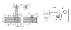
- FIG. 1is a schematic diagram of an example network including bi-directional indexing terminals and separate splitter terminals;
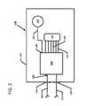
- FIG. 2is a schematic block diagram of a splitter terminal disposed external of the indexing terminals shown in FIG. 1 .
- FIG. 1illustrates a fiber optic network 100 including an optical cable arrangement 102 having optical fibers 103 that define first optical lines A 1 -An.
- the cable arrangement 102includes between two and forty-eight optical fibers 103 .
- the cable arrangement 102includes between eight and sixteen optical fibers 103 .
- the cable arrangement 102includes between sixteen and thirty-two optical fibers 103 .
- the cable arrangement 102includes between twelve and twenty-four optical fibers 103 .
- the cable arrangement 102includes twenty-four optical fibers 103 .
- cables arrangements 102 with even larger fiber countsare contemplated.
- One or more indexing terminals 110are disposed along the optical cable arrangement 102 .
- multiple indexing terminals 110are daisy chained together using the cable arrangement 102 .
- each indexing terminal 110is disposed at an intermediate location along the cable arrangement 102 .
- the first optical lines A 1 -Anpass through the indexing terminals 110 .
- the first optical lines A 1 -An of the optical cable arrangement 102are indexed at the indexing terminal 110 so that at least one of the first optical lines A 1 -An drops off at the indexing terminal 110 .
- the cable arrangement 102includes one or more multi-fiber cables. Opposite ends of the multi-fiber cables are terminated at optical connectors. In certain implementations, one or both multi-fiber cables can be configured to be ruggedly connected to indexing terminals 110 .
- a connectionis “ruggedized” when the optical connector and optical adapter are configured to environmentally seal together and are configured to robustly connect together.
- a “robust connection”refers to a connection of an optical connector to an optical adapter such that the optical connector can withstand an axial load of at least 100 pounds without pulling out of the optical adapter.
- a robust connection structureincludes twist-to-lock connections.
- a twist-to-lock connectionincludes a bayonet connection.
- a twist-to-lock connectionincludes a threaded connection.
- the cable arrangement 102includes multiple multi-fiber cables 104 terminated at a first end by a first optical connector 105 and terminated at a second end by a second optical connector 115 .
- the first optical connector 105is a ruggedized optical connector.
- the optical fibers 103are disposed at the first optical connector 105 in sequential positions.
- the optical fibers 103are also disposed at the second optical connector 115 in sequential positions.
- the optical fibers 103are loose within the cables 104 .
- the optical fibers 103are arranged in fiber ribbons.
- the first optical lines A 1 -Anare indexed in a first indexing direction F along the optical cable arrangement 102 .
- one or more of the first optical lines A 1 -Anprogressively drops off at various indexing locations (e.g., indexing terminals 110 ) along the cable arrangement 102 .
- the optical fibers 103 of each fiber ribbon R 1 , R 2are disposed at the first optical connector 105 in sequential positions P F1 -P FN , P S1 -P SN , respectively.
- the first optical lines A 1 -Anare indexed in the first direction F by dropping off at least the first optical line A 1 at the first sequential position P F1 of the first optical connector 105 .
- a first optical line A 2 extending from a second sequential position P F2 at the first optical connector 105also drops off at the indexing terminal 110 .
- the remaining first optical linesextend from the first optical connector 105 to the first available position in sequence at the second connector 115 beginning with the first optical line A 3 extending from a third sequential position P F3 at the first optical connector 105 to a first sequential position P S1 at the second optical connector 115 .
- the sequential positions at the connectors 105 , 115are disposed in one or more rows R 1 , R 2 .
- the first optical connector 105can include a first row R 1 of sequential positions P F1 -P FX and a second row R 1 of sequential positions P FA -P FN .
- each row R 1 , R 2 of positionsis separately indexed. Indexing the ribbons R 1 , R 2 separately avoids the need to cross-index the optical fibers between the ribbons R 1 , R 2 .
- first optical lines extending from the first sequential position P F1 , P FA of each row R 1 , R 2can drop off at the indexing terminal 110 while a first optical lines extending from subsequent sequential positions (e.g., the third sequential positions) can be routed to the first available position in sequence at a corresponding row on the second optical connector 115 . If an optical fiber 103 extends from one of the positions in a first row R 1 at the first optical connector 105 , then the optical fiber 103 will extend to one of the positions in the first row at the second optical connector 115 and will not extend to a different row at the second connector 115 .
- the first optical linescan be dropped off in any desired configuration.
- the first optical linescould be indexed non-sequentially or sequentially starting with the last sequential position.
- a greater or lesser number of first optical linescan drop off at the indexing terminal 110 .
- the example indexing terminals 110 shown in FIG. 1includes a closure 111 defining a first cable port 112 , a second cable port 114 , and a third cable port 116 .
- the first optical lines A 1 -An of the optical cable arrangement 102pass through the first cable port 112 and are indexed at the second cable port 114 .
- a first optical line that drops off at the indexing terminal 110is routed to the third cable port (i.e., drop port) 116 .
- the third cable porti.e., drop port
- multiple first optical linesdrop off at the indexing terminal 110 .
- the first optical lines that drop offare routed to the third cable port 116 .
- the first optical lines that drop offare routed to multiple drop ports including the third cable port 116 .
- each indexing terminal 110is associated with one of the multi-fiber cables 104 of the cable arrangement 102 .
- the cable 104is pre-cabled within the indexing terminal 110 at a factory prior to installation in the field.
- the first optical connector 105 of the cable 104is disposed external of the indexing terminal 110 and the second optical connector 115 of the cable 104 is disposed internal of the indexing terminal 110 .
- the cable 104can extend into the closure 111 through a sealed pass-through port 112 and the second connector 115 can be received at the second cable port 114 .
- the second connector 115can be received at a ruggedized external port of a ruggedized optical adapter.
- the internal port of the optical adapteris non-ruggedized.
- an optical adapteris “ruggedized” when at least one port of the optical adapter is configured to provide a ruggedized connection to an optical connector received at the port. If a ruggedized optical adapter is carried by a closure, then the ruggedized optical adapter will be environmentally sealed (e.g., using a gasket) to the closure.
- a ruggedized portcan include a seal (e.g., a gasket) disposed therein to press against an optical connector received in the port.
- the ruggedized portcan include a wall or other structure against which a seal on a connector may press when the connector is received at the port.
- non-ruggedized portsinclude ports configured to receive standard single fiber connectors (e.g., SC plugs, SC adapters, LC plugs, LC adapters, ST plugs, ST adapters, etc.) or standard multi-fiber connectors (e.g., MPO plugs and/or MPO adapters).
- SC plugsSC plugs
- SC adaptersLC plugs
- LC adaptersLC adapters
- ST plugsST adapters
- etc.standard multi-fiber connectors
- MPO plugs and/or MPO adaptersstandard multi-fiber connectors
- the cable 104extends out of the closure 111 a sufficient distance so that the first optical connector 105 can be received at the second cable port 114 (e.g., at a ruggedized external port of an optical adapter) of another indexing terminal 110 or other equipment.
- optical adapterscan be disposed at both the first and second cable ports 112 , 114 of each indexing terminal 110 .
- Internal cabling within each indexing terminal 110connects the first, second, and third cable ports 112 , 114 , 116 of the indexing terminal 110 .
- non-indexed multi-fiber cablescan be routed to the first and second cable ports 112 , 114 .
- the network 100has a bidirectional indexing architecture.
- the optical fibers 103 of the optical cable arrangement 102also can define second optical lines B 1 -Bn that are indexed in a second indexing direction S along the optical cable arrangement 102 .
- the second indexing direction Sis different from the first indexing direction F.
- the directions F and Sare opposites.
- At least one of the second optical lines B 1 -Bndrops off at each indexing terminal 110 .
- the first optical lines A 1 -A 12 and the second optical lines B 1 -B 12extend to a common location, such as a central office.
- each end of the optical cable arrangement 102can be received at a central office (e.g., the same central office or a different central office).
- a central officee.g., the same central office or a different central office.
- the optical fiber lines A 1 -A 12 and the optical fiber lines B 1 -B 12cooperate to form a fiber loop.
- the first and second fiberscan be routed to different locations.
- the second optical lines B 1 -Bnare indexed in the second direction S by dropping off at least the second optical line at the last sequential position P SN of the second optical connector 115 .
- a second optical line extending from a penultimate sequential position at the second optical connector 115also drops off at the indexing terminal 110 .
- a second optical line extending from an antepenultimate sequential position at the second optical connector 115extends to the last sequential position P FN at the first optical connector 105 .
- the second optical linescould be indexed non-sequentially or sequentially starting with the first sequential position.
- a greater or lesser number of second optical linescan drop off at the indexing terminal 110 .
- first optical lines extending from the first two sequential positions P F1 , P F2 of a first ribbon R 1 at the first optical connector 105 , first optical lines extending from the first two sequential positions of a second ribbon R 2 at the first optical connector 105 , second optical lines extending from the last two sequential positions of the first ribbon R 1 at the second optical connector 115 , and second optical lines extending from the last two sequential positions of a second ribbon R 2are dropped off at the indexing terminal 110 .
- other routing configurationsare possible.
- the indexing terminal 110is cabled so that the first and second optical lines that drop off at the indexing terminal 110 are routed to a common drop port (e.g., the third cable port 116 ).
- the first and second optical lines that drop offcan be routed to multiple drop ports 116 .
- the first optical lines that drop offcan be routed to one drop port and the second optical lines that drop off can be routed to another drop port.
- each drop port 116can receive one of the first optical lines that drops off and one of the second optical lines that drops off.
- a splitter terminal 130is disposed external of the indexing terminals 110 .
- each indexing terminal 110has a corresponding splitter terminal 130 .
- each indexing terminal 110may be associated with multiple splitter terminals 130 .
- the splitter terminal 130includes an enclosure 131 that houses an optical splitter 180 (see FIG. 2 ).
- the enclosure 131can house multiple optical splitters.
- the optical splitter 180is configured to split (e.g., power split) any optical signal received at the splitter input 181 into multiple (e.g., two, three, four, eight, sixteen, thirty-two, sixty-four, etc.) optical signals that are each output onto a separate optical fiber 185 .
- An output cable 120includes an optical fiber 123 that optically couples one of the first optical lines (e.g., first optical line A S ) that dropped off at the indexing terminal 110 to an input 181 of the optical splitter 180 at the splitter terminal 130 .
- the output cable 120also includes an optical fiber 123 that optically couples one of the second optical lines (e.g., second optical line B 1 ) that dropped off at the indexing terminal 110 to a second input 181 of the optical splitter 180 at the splitter terminal 130 .
- the optical splitter 180receives optical signals carried over the first optical line A 1 and optical signals carried over the second optical line B 1 .
- First outputs 185 of the optical splitter 180are routed to a network output port 134 of the splitter terminal 130 .
- the first outputs 185include optical signals split from the first optical line received at the splitter input 181 .
- the first outputs 185include optical signals split from the second optical line received at the splitter input 181 .
- the first outputs 185include optical signals split from the first optical lines and optical signals split from the second optical lines.
- An additional output 187 of the optical splitter 180is routed to a subscriber output port 136 of the splitter terminal 130 .
- the additional output 187includes optical signals split from the first optical line received at the splitter input 181 .
- the additional output 187includes optical signals split from the second optical line received at the splitter input 181 . In certain examples, the additional output 187 includes optical signals split from the first optical lines and optical signals split from the second optical lines. In other implementations, however, the splitter terminal 130 may include only one or more network output ports 134 (i.e., multi-fiber output ports). In still other implementations, the splitter terminal 130 may include only one or more subscriber output ports 136 (i.e., single-fiber output ports).
- the subscriber output port 136 of the splitter enclosure 131is one of multiple subscriber output ports 136 that each receive optical signals output by the optical splitter.
- the splitter enclosure 131defines about two to about sixteen subscriber output ports 136 .
- the splitter enclosure 131defines about four to about twelve subscriber output ports 136 .
- the splitter enclosure 131defines about six subscriber output ports 136 .
- the splitter enclosure 131defines about eight subscriber output ports 136 .
- the splitter enclosure 131can define a greater or lesser number of subscriber output ports 136 .
- each subscriber output port 136receives one split line from the optical splitter. Accordingly, a single-fiber cable can be plugged into each subscriber output port 136 at the splitter terminal 130 to receive the optical signals carried over the split line.
- the network output port 134 of the splitter enclosure 131is one of multiple network output ports 134 that each receive optical signals output by the optical splitter.
- the splitter enclosure 131defines two network output ports 134 .
- the splitter enclosure 131can define a greater or lesser number of network output ports 134 .
- each network output port 134receives multiple split lines from the optical splitter. Accordingly, a multi-fiber cable can be plugged into each network output port 134 at the splitter terminal 130 to receive the optical signals carried over the split lines.
- the splitter enclosure 131also defines an input port 132 . Signals received at the input port 132 are directed to the input of the optical splitter.
- the input port 132includes a sealed pass-through at which a portion of the output cable 120 can enter the splitter enclosure 131 .
- the input port 132includes a ruggedized optical adapter having a ruggedized external port. In such an example, a ruggedized optical connector of the output cable 120 can be received at the ruggedized external port so that optical signals carried over the output cable 120 are directed to the splitter input.
- the splitter enclosure 131includes multiple input ports 132 .
- the output cable 120extends from a first end 121 to a second end 122 .
- the first end 121is coupled (e.g., robustly connected) to the third cable port 116 of the first indexing terminal 110 .
- the first end 121is terminated by an optical connector (e.g., a ruggedized multi-fiber connector) configured to be received at the third cable port 116 .
- the first end 121can be aligned with a multi-fiber optic connector (e.g., a non-ruggedized connector) 117 that holds the dropped optical lines and that is received at an interior of the third cable port 116 .
- the first end 121is disposed within the closure 111 and coupled (e.g., spliced) to the first and second optical lines that dropped off at the indexing terminal 110 .
- At least part of the second end 122 of the output cable 120is optically coupled to the input of the optical splitter.
- the at least part of the second end 122is disposed within the splitter enclosure 131 so that a portion of the output cable 120 passes through the input port 132 of the splitter enclosure 131 .
- the at least part of the second end 122is terminated by an optical connector 125 (e.g., a ruggedized optical connector) that is received at an input port 132 of the splitter terminal 132 .
- the output cable 120includes multiple optical fibers 123 that each optically coupled to one of the first and second optical lines that drop off at the indexing terminal 110 .
- each optical fiber 123is optically coupled to one of the dropped lines.
- the optical fibers 123 of the output cable 120are separately terminated by ruggedized optical connectors 125 (e.g., DLX connectors) at the second end 122 of the output cable 120 . In such implementations, less than all of the optical fibers 123 are routed to the splitter terminal 130 .
- the optical fiber 123 carrying the dropped first optical line A S and the optical fiber 123 carrying the dropped second optical line B 1are routed to the splitter input ports 132 .
- the output cable 120includes a flexible service terminal (FST) 128 between the first and second ends 121 , 122 .
- FSTflexible service terminal
- the portion of the output cable 120 extending between the first end 121 and the FST 128includes multiple fibers enclosed within a jacket; the portion of the output cable 120 extending between the FST 128 and the second end 122 includes jacketed cable segments 124 each having one of the optical fibers 123 .
- the FST 128includes a flexible closure at the transition point between the first portion of the output cable 120 and the second portion of the output cable 120 .
- each of the ruggedized optical connectors 125 terminating the dropped linesincludes a single-fiber ruggedized optical connector (e.g., a DLX connector).
- the network architectureis depicted schematically in FIG. 1 and that additional multi-fiber optical connectors (e.g., ruggedized connectors) can be added into the architecture. Additionally, single fiber optical ports, such as ruggedized fiber optic adapters, can be provided at the drop ports of the indexing terminals. Moreover, various indexing terminals can be strung serially together in a daisy chain to form the architecture.
- the multi-fiber optical connectorsare 12-fiber optical connectors. In other examples, the multi-fiber optical connectors can include at least 4, 6, 8, 12, 24 or more optical fibers.
- the cable arrangement 102is deployed by installing the indexing terminals 110 at desired locations in the field.
- the indexing terminals 110are pre-cabled at the factory before being deployed. Accordingly, the indexing terminals utilize plug-and-play connections in the field.
- each indexing terminal 110is associated with a multi-fiber cable 104 .
- the optical connector 105 of the associated cable 104is routed to an adjacent indexing terminal 110 or other network equipment.
- the first optical connector 105is robustly fastened at a ruggedized external port of an optical adapter disposed at the second cable port 114 of the adjacent indexing terminal 110 .
- the optical adapteraligns the optical fibers of the connector 105 to the optical fibers of the connector 115 received at the internal port of the adjacent terminal.
- the first optical connector 105 of a subsequent indexing terminal 110can be robustly fastened at a ruggedized external port of the optical adapter disposed at the second cable port 114 of the indexing terminal 110 .
- a ruggedized optical adapter having a ruggedized external portis also disposed at the first cable port 112 .
- non-indexed multi-fiber cablescan be routed between the first cable port 112 of an indexing terminal and the second cable port 114 of a previous indexing terminal in the network.
- one or more of the dropped optical linescan be routed to the splitter terminal 130 using a plug-and-play connection.
- a multi-fiber connector terminating the first end 121 of an output cable 120can be received at the third cable port 116 of the indexing terminal 110 .
- a ruggedized multi-fiber connectorcan be robustly fastened to a ruggedized external port of an optical adapter disposed at the third cable port 116 .
- the optical adapteraligns the optical fibers of the output cable 120 to the dropped optical fibers received at the interior port. Accordingly, optical signals carried over the dropped optical lines are carried over the optical fibers 123 of the output cable 120 .
- One or more ends 122 of the output cable 120can be routed to one or more splitter terminals 130 as described above.
- fewer than all of the optical fibers 123 of the output cable 120are routed to the splitter terminal 130 .
- one or more of the optical fibers 123can be used in point-to-point (PTP) connections between a subscriber and a central office.
- PTPpoint-to-point
- a PTP connectionprovides unsplit signals between the central office and a subscriber. Unsplit signals provide higher bandwidth to the subscriber. Accordingly, PTP connections are useful for connecting to a Distributed Antenna System (DAS), a WIFI network, a camera (e.g., security camera, traffic camera, etc.), a traffic light, or any other subscriber.
- DASDistributed Antenna System
- WIFIWireless Fidelity
- camerae.g., security camera, traffic camera, etc.
Landscapes
- Physics & Mathematics (AREA)
- General Physics & Mathematics (AREA)
- Optics & Photonics (AREA)
- Light Guides In General And Applications Therefor (AREA)
Abstract
Description
Claims (20)
Priority Applications (7)
| Application Number | Priority Date | Filing Date | Title |
|---|---|---|---|
| US14/876,140US9851525B2 (en) | 2014-10-06 | 2015-10-06 | Facilitating installation of fiber optic networks |
| US15/840,662US20180164527A1 (en) | 2014-10-06 | 2017-12-13 | Facilitating installation of fiber optic networks |
| US16/259,594US10598887B2 (en) | 2014-10-06 | 2019-01-28 | Facilitating installation of fiber optic networks |
| US16/822,337US11156793B2 (en) | 2014-10-06 | 2020-03-18 | Facilitating installation of fiber optic networks |
| US17/509,994US20220113485A1 (en) | 2014-10-06 | 2021-10-25 | Facilitating installation of fiber optic networks |
| US18/295,495US20230244053A1 (en) | 2014-10-06 | 2023-04-04 | Facilitating installation of fiber optic networks |
| US18/440,522US20240264403A1 (en) | 2014-10-06 | 2024-02-13 | Facilitating installation of fiber optic networks |
Applications Claiming Priority (2)
| Application Number | Priority Date | Filing Date | Title |
|---|---|---|---|
| US201462060289P | 2014-10-06 | 2014-10-06 | |
| US14/876,140US9851525B2 (en) | 2014-10-06 | 2015-10-06 | Facilitating installation of fiber optic networks |
Related Parent Applications (1)
| Application Number | Title | Priority Date | Filing Date |
|---|---|---|---|
| US62060289Continuation | 2014-10-06 |
Related Child Applications (1)
| Application Number | Title | Priority Date | Filing Date |
|---|---|---|---|
| US15/840,662ContinuationUS20180164527A1 (en) | 2014-10-06 | 2017-12-13 | Facilitating installation of fiber optic networks |
Publications (2)
| Publication Number | Publication Date |
|---|---|
| US20160097909A1 US20160097909A1 (en) | 2016-04-07 |
| US9851525B2true US9851525B2 (en) | 2017-12-26 |
Family
ID=55632727
Family Applications (7)
| Application Number | Title | Priority Date | Filing Date |
|---|---|---|---|
| US14/876,140ActiveUS9851525B2 (en) | 2014-10-06 | 2015-10-06 | Facilitating installation of fiber optic networks |
| US15/840,662AbandonedUS20180164527A1 (en) | 2014-10-06 | 2017-12-13 | Facilitating installation of fiber optic networks |
| US16/259,594ActiveUS10598887B2 (en) | 2014-10-06 | 2019-01-28 | Facilitating installation of fiber optic networks |
| US16/822,337ActiveUS11156793B2 (en) | 2014-10-06 | 2020-03-18 | Facilitating installation of fiber optic networks |
| US17/509,994AbandonedUS20220113485A1 (en) | 2014-10-06 | 2021-10-25 | Facilitating installation of fiber optic networks |
| US18/295,495AbandonedUS20230244053A1 (en) | 2014-10-06 | 2023-04-04 | Facilitating installation of fiber optic networks |
| US18/440,522PendingUS20240264403A1 (en) | 2014-10-06 | 2024-02-13 | Facilitating installation of fiber optic networks |
Family Applications After (6)
| Application Number | Title | Priority Date | Filing Date |
|---|---|---|---|
| US15/840,662AbandonedUS20180164527A1 (en) | 2014-10-06 | 2017-12-13 | Facilitating installation of fiber optic networks |
| US16/259,594ActiveUS10598887B2 (en) | 2014-10-06 | 2019-01-28 | Facilitating installation of fiber optic networks |
| US16/822,337ActiveUS11156793B2 (en) | 2014-10-06 | 2020-03-18 | Facilitating installation of fiber optic networks |
| US17/509,994AbandonedUS20220113485A1 (en) | 2014-10-06 | 2021-10-25 | Facilitating installation of fiber optic networks |
| US18/295,495AbandonedUS20230244053A1 (en) | 2014-10-06 | 2023-04-04 | Facilitating installation of fiber optic networks |
| US18/440,522PendingUS20240264403A1 (en) | 2014-10-06 | 2024-02-13 | Facilitating installation of fiber optic networks |
Country Status (4)
| Country | Link |
|---|---|
| US (7) | US9851525B2 (en) |
| EP (1) | EP3205034A4 (en) |
| MX (1) | MX2017004130A (en) |
| WO (1) | WO2016057411A1 (en) |
Cited By (5)
| Publication number | Priority date | Publication date | Assignee | Title |
|---|---|---|---|---|
| US10598887B2 (en)* | 2014-10-06 | 2020-03-24 | Commscope Technologies Llc | Facilitating installation of fiber optic networks |
| US10690875B2 (en) | 2016-09-06 | 2020-06-23 | CommScope Connectivity Belgium BVBA | Indexing architecture including an optical fiber cable fan-out arrangement |
| US10790899B2 (en)* | 2017-01-12 | 2020-09-29 | Commscope Technologies Llc | Optical tapping in an indexing architecture |
| US11327254B2 (en)* | 2014-12-19 | 2022-05-10 | Commscope Technologies Llc | Indexing terminal with splitter |
| US11579392B2 (en) | 2018-08-29 | 2023-02-14 | Commscope Technologies Llc | Indexing cable arrangement and enclosure for use therewith |
Families Citing this family (14)
| Publication number | Priority date | Publication date | Assignee | Title |
|---|---|---|---|---|
| US10317640B2 (en) | 2015-02-24 | 2019-06-11 | Commscope Technologies Llc | Indexing terminal arrangement |
| US10151897B2 (en) | 2016-01-26 | 2018-12-11 | Commscope Technologies Llc | Fiber indexing systems |
| GB2547681A (en)* | 2016-02-25 | 2017-08-30 | British Telecomm | Apparatus |
| MX2019001845A (en) | 2016-08-15 | 2019-05-09 | Commscope Technologies Llc | Indexing architecture including a fan-out arrangement. |
| US10678002B2 (en) | 2016-08-16 | 2020-06-09 | Commscope Technologies Llc | Loop back connector to utilize reverse drops in an indexing system; and methods |
| US10606006B2 (en) | 2016-09-20 | 2020-03-31 | Clearfield, Inc. | Optical fiber distribution systems and components |
| US10859781B2 (en) | 2016-09-20 | 2020-12-08 | Clearfield, Inc. | Optical fiber distribution systems and components |
| WO2018085397A1 (en) | 2016-11-02 | 2018-05-11 | Commscope Technologies Llc | Fiber optic network architecture with parallel indexed and non-indexed fiber paths |
| US9989705B2 (en) | 2016-11-04 | 2018-06-05 | Corning Optical Communications LLC | Fiber optic distribution network employing fiber optic distribution assemblies of the same type, and related devices, components, and methods |
| US10317639B2 (en) | 2016-11-11 | 2019-06-11 | CommScope Connectivity Belgium BVBA | Fiber optic network architecture |
| WO2022236024A1 (en)* | 2021-05-06 | 2022-11-10 | Commscope Technologies Llc | Integrating indexing & point-to-point services |
| JP2022183873A (en)* | 2021-05-31 | 2022-12-13 | 住友電気工業株式会社 | fiber optic ribbon |
| CN114545577B (en)* | 2022-02-18 | 2023-09-15 | 烽火通信科技股份有限公司 | Modularized optical cable assembly and networking topological structure |
| WO2024011242A1 (en)* | 2022-07-07 | 2024-01-11 | Commscope Technologies Llc | Indexing architecture with enhanced signal path routing flexibility |
Citations (61)
| Publication number | Priority date | Publication date | Assignee | Title |
|---|---|---|---|---|
| US4630886A (en) | 1984-04-16 | 1986-12-23 | At&T Bell Laboratories | Lightguide distributing unit |
| US5204921A (en) | 1991-01-08 | 1993-04-20 | Nippon Telegraph And Telephone Corporation | Automated optical main distributing frame system |
| US5321541A (en)* | 1991-12-12 | 1994-06-14 | At&T Bell Laboratories | Passive optical communication network with broadband upgrade |
| US5539564A (en) | 1993-09-22 | 1996-07-23 | Nippon Telegraph And Telephone Corporation | Point-to-multipoint optical transmission system |
| JPH1032545A (en) | 1996-07-18 | 1998-02-03 | Matsushita Electric Ind Co Ltd | Optical connection method in optical communication system |
| US6256443B1 (en) | 1998-07-24 | 2001-07-03 | Nippon Telegraph And Telephone Corporation | Optical fiber distribution module for holding an optical fiber cord and fiber distribution system using optical fiber cords |
| US6351582B1 (en) | 1999-04-21 | 2002-02-26 | Nortel Networks Limited | Passive optical network arrangement |
| US20030103750A1 (en) | 2001-11-30 | 2003-06-05 | Laporte Richard B. | Distribution terminal for network access point |
| US20050105873A1 (en) | 2003-11-17 | 2005-05-19 | Fiber Optic Network Solutions Corporation | Systems and methods for managing optical fibers and components within an enclosure in an optical communications networks |
| WO2005117300A1 (en) | 2004-05-25 | 2005-12-08 | Agency For Science, Technology And Research | Method and system for data transfer |
| US20060008231A1 (en) | 2003-11-17 | 2006-01-12 | Fiber Optic Network Solutions Corporation | Hinged parking in fiber distribution hubs |
| US20060233506A1 (en) | 2005-04-19 | 2006-10-19 | Michael Noonan | Fiber breakout with integral connector |
| US20060269208A1 (en) | 2005-05-31 | 2006-11-30 | Barry Allen | Optical network architecture, terminals for use in such networks and methods for using the same |
| EP1746858A1 (en) | 2005-07-20 | 2007-01-24 | Siemens Aktiengesellschaft | Three way coupler for a passive optical network |
| US20070031100A1 (en) | 2005-08-04 | 2007-02-08 | Garcia Cesar G | Optical fiber distribution cabinet |
| US7198409B2 (en) | 2003-06-30 | 2007-04-03 | Adc Telecommunications, Inc. | Fiber optic connector holder and method |
| US7218827B2 (en) | 2004-06-18 | 2007-05-15 | Adc Telecommunications, Inc. | Multi-position fiber optic connector holder and method |
| US7233731B2 (en) | 2003-07-02 | 2007-06-19 | Adc Telecommunications, Inc. | Telecommunications connection cabinet |
| US20070195693A1 (en) | 2004-04-14 | 2007-08-23 | Congqi Li | Method and device for implementing och-spring in wavelength division multiplexing systems |
| US20070274720A1 (en) | 2006-05-25 | 2007-11-29 | Menasco Heyward E Jr | Optical Network Unit Activation |
| US20080025725A1 (en) | 2003-01-03 | 2008-01-31 | Tellabs Bedford, Inc. | Fiber to the Home Broadband Home Unit |
| WO2008079329A2 (en) | 2006-12-21 | 2008-07-03 | Corning Cable Systems Llc | Preconnectorized fiber optic local convergence points |
| US7418181B2 (en) | 2006-02-13 | 2008-08-26 | Adc Telecommunications, Inc. | Fiber optic splitter module |
| FR2914753A1 (en) | 2007-04-03 | 2008-10-10 | Schneider Electric Ind Sas | Optical fiber distribution box for local computing communication infrastructure, has male and female connectors with connection zones connected to continuous optical guides, respectively, where one zone is connected to distributed guides |
| US20080285916A1 (en)* | 2005-11-15 | 2008-11-20 | Zolo Technologies, Inc. | All-Fiber Architecture for an Embedded Flight Sensor for Aeropropulsion Applications |
| US20080317468A1 (en)* | 2007-06-19 | 2008-12-25 | Villarruel Fernando X | Amplified Wavelength Broadband Video Distribution Architectures Using An External Waveguide |
| US20090041457A1 (en) | 2005-10-11 | 2009-02-12 | Intellambda Systems, Inc. | Modular WSS-based communications system with colorless add/drop interfaces |
| JP2009038650A (en) | 2007-08-02 | 2009-02-19 | Osaka Prefecture Univ | OADM (Optical Add Drop Multiplexer) module and OADM unit to which it is mounted |
| JP2009086464A (en) | 2007-10-01 | 2009-04-23 | Nippon Tsushin Denzai Kk | Optical cable connection closure |
| US7546018B2 (en) | 2007-01-13 | 2009-06-09 | Ofs Fitel, Llc | Fiber optic cabling for multi-dwelling unit (MDU) and commercial building deployments |
| KR20090114191A (en) | 2008-04-29 | 2009-11-03 | 주식회사 다산네트웍스 | Apparatus and method for handling subscriber communication failure in passive optical network operated by L3 / L2 network |
| US20090294016A1 (en) | 2008-05-27 | 2009-12-03 | Derek Sayres | Flexible extruded cable molding system, methods, and tools |
| US20090317047A1 (en) | 2008-06-19 | 2009-12-24 | Adc Telecommunications, Inc. | Methods and systems for distributing fiber optic telecommunications services to local area |
| US7668425B1 (en) | 2008-11-07 | 2010-02-23 | Corning Cable Systems Llc | Bi-directional cable assembly with bend-improved fiber tether |
| US20100092133A1 (en) | 2008-10-14 | 2010-04-15 | Conner Mark E | Optical Connection Terminal Having Port Mapping Scheme |
| US20100098407A1 (en) | 2008-10-21 | 2010-04-22 | Teknovus, Inc. | Method and system for protection switching in ethernet passive optical networks |
| US20100142888A1 (en) | 2008-12-10 | 2010-06-10 | Verizon Corporate Resources Group Llc | Compact fiber distribution hub |
| WO2010093794A1 (en) | 2009-02-11 | 2010-08-19 | Corning Cable Systems Llc | Reconfigurable multi-zoned fiber optic network architecture having fiber optic devices |
| US20100226654A1 (en) | 2009-03-05 | 2010-09-09 | Adc Telecommunications, Inc. | Methods, Systems and Devices for Integrating Wireless Technology into a Fiber Optic Network |
| US20100303408A1 (en)* | 2009-05-27 | 2010-12-02 | Conner Mark E | Port Mapping for Series Connected Fiber Optic Terminals |
| US20100329624A1 (en) | 2008-02-27 | 2010-12-30 | Junsheng Zhou | High density fiber distribution hub |
| US20110026894A1 (en) | 2009-07-01 | 2011-02-03 | Paula Rudenick | Wall-mounted fiber distribution hub |
| US20110058785A1 (en) | 2009-09-04 | 2011-03-10 | Adc Telecommunications, Inc. | Pedestal terminal with swing frame |
| US20110091170A1 (en) | 2009-10-21 | 2011-04-21 | Adc Telecommunications, Inc. | Fiber distribution hub and cable for use therewith |
| US20110097052A1 (en) | 2009-10-21 | 2011-04-28 | Solheid James J | Fiber Access Terminal Mounted at a Mid-Span Access Location of a Telecommunications Cable |
| US20110129226A1 (en) | 2008-07-21 | 2011-06-02 | Tyco Electronics Raychem Bvba | Optical fibre networks |
| US20110135307A1 (en)* | 2009-12-04 | 2011-06-09 | Conner Mark E | Fiber Optic Terminals, Systems, and Methods for Network Service Management |
| US20110158598A1 (en) | 2009-11-25 | 2011-06-30 | Adc Telecommunications, Inc. | Methods, Systems and Devices for Providing Fiber-to-the-Desktop |
| US20110222831A1 (en) | 2008-10-09 | 2011-09-15 | Songhua Cao | Fiber optic terminal having adapter panel supporting both input and output fibers from an optical splitter |
| WO2011130472A2 (en) | 2010-04-14 | 2011-10-20 | Corning Cable Systems Llc | Port mapping in fiber optic network devices |
| US20110274403A1 (en) | 2010-05-07 | 2011-11-10 | Adc Telecommunications, Inc. | Fiber distribution hub with pass-through interfaces |
| US20110293277A1 (en) | 2009-02-11 | 2011-12-01 | Daniel Aurel Bradea | Reconfigurable multi-zoned fiber optic network architecture having fiber optic devices |
| US20120027355A1 (en) | 2010-08-02 | 2012-02-02 | Adc Telecommunications, Inc. | Architecture for a Fiber Optic Network |
| US20120321309A1 (en) | 2011-06-20 | 2012-12-20 | Barry Richard A | Optical architecture and channel plan employing multi-fiber configurations for data center network switching |
| US20120328294A1 (en) | 2011-06-23 | 2012-12-27 | Verizon Patent And Licensing Inc. | High speed passive optical network architecture |
| US20130163984A1 (en) | 2011-12-22 | 2013-06-27 | Tyco Electronics Corporation | Fiber Optic Wall Plate with Redundancy System |
| US20130216187A1 (en) | 2011-08-17 | 2013-08-22 | Douglas Ferris Dowling | Distributed passive optical networks |
| US20140105539A1 (en)* | 2010-04-14 | 2014-04-17 | Mark Edward Conner | Port mapping in fiber optic network devices |
| US20140226939A1 (en)* | 2011-09-22 | 2014-08-14 | OFS Fitel ,LLC | Optical fiber distribution cables |
| US20140254986A1 (en) | 2012-03-30 | 2014-09-11 | Adc Telecommunications, Inc. | Passive distribution system using fiber indexing |
| US20150378112A1 (en)* | 2014-06-27 | 2015-12-31 | Adc Telecommunications, Inc. | Indexing terminals for supporting a bidirectional indexing architecture |
Family Cites Families (5)
| Publication number | Priority date | Publication date | Assignee | Title |
|---|---|---|---|---|
| US6694083B2 (en)* | 2001-11-14 | 2004-02-17 | Harris Corporation | Device including a fiber optic cable harness and associated methods |
| ES2456044T3 (en)* | 2007-04-03 | 2014-04-21 | Schneider Electric Industries Sas | Bypass device for a fiber optic transmission line |
| US7756371B1 (en)* | 2009-01-30 | 2010-07-13 | Corning Cable Systems Llc | Optical fiber interconnection devices and systems using same |
| US20120189259A1 (en)* | 2010-12-15 | 2012-07-26 | Leviton Manufacturing Co., Inc. | Pre-terminated fiber devices, systems, and methods |
| MX2017004130A (en)* | 2014-10-06 | 2017-10-31 | Adc Telecommunications Inc | Facilitating installation of fiber optic networks. |
- 2015
- 2015-10-05MXMX2017004130Apatent/MX2017004130A/enunknown
- 2015-10-05EPEP15849281.9Apatent/EP3205034A4/ennot_activeWithdrawn
- 2015-10-05WOPCT/US2015/054038patent/WO2016057411A1/enactiveApplication Filing
- 2015-10-06USUS14/876,140patent/US9851525B2/enactiveActive
- 2017
- 2017-12-13USUS15/840,662patent/US20180164527A1/ennot_activeAbandoned
- 2019
- 2019-01-28USUS16/259,594patent/US10598887B2/enactiveActive
- 2020
- 2020-03-18USUS16/822,337patent/US11156793B2/enactiveActive
- 2021
- 2021-10-25USUS17/509,994patent/US20220113485A1/ennot_activeAbandoned
- 2023
- 2023-04-04USUS18/295,495patent/US20230244053A1/ennot_activeAbandoned
- 2024
- 2024-02-13USUS18/440,522patent/US20240264403A1/enactivePending
Patent Citations (101)
| Publication number | Priority date | Publication date | Assignee | Title |
|---|---|---|---|---|
| US4630886A (en) | 1984-04-16 | 1986-12-23 | At&T Bell Laboratories | Lightguide distributing unit |
| US5204921A (en) | 1991-01-08 | 1993-04-20 | Nippon Telegraph And Telephone Corporation | Automated optical main distributing frame system |
| US5321541A (en)* | 1991-12-12 | 1994-06-14 | At&T Bell Laboratories | Passive optical communication network with broadband upgrade |
| US5539564A (en) | 1993-09-22 | 1996-07-23 | Nippon Telegraph And Telephone Corporation | Point-to-multipoint optical transmission system |
| JPH1032545A (en) | 1996-07-18 | 1998-02-03 | Matsushita Electric Ind Co Ltd | Optical connection method in optical communication system |
| US6256443B1 (en) | 1998-07-24 | 2001-07-03 | Nippon Telegraph And Telephone Corporation | Optical fiber distribution module for holding an optical fiber cord and fiber distribution system using optical fiber cords |
| US6351582B1 (en) | 1999-04-21 | 2002-02-26 | Nortel Networks Limited | Passive optical network arrangement |
| US20030103750A1 (en) | 2001-11-30 | 2003-06-05 | Laporte Richard B. | Distribution terminal for network access point |
| US20080025725A1 (en) | 2003-01-03 | 2008-01-31 | Tellabs Bedford, Inc. | Fiber to the Home Broadband Home Unit |
| US8210756B2 (en) | 2003-06-30 | 2012-07-03 | Adc Telecommunications, Inc. | Fiber optic connector holder and method |
| US20130064510A1 (en) | 2003-06-30 | 2013-03-14 | Adc Telecommunications, Inc. | Fiber optic connector holder and method |
| US7980768B2 (en) | 2003-06-30 | 2011-07-19 | Adc Telecommunications, Inc. | Fiber optic connector holder and method |
| US7841775B2 (en) | 2003-06-30 | 2010-11-30 | Adc Telecommunications, Inc. | Connector storage system |
| US7407330B2 (en) | 2003-06-30 | 2008-08-05 | Adc Telecommunications, Inc. | Fiber optic connector holder and method |
| US7198409B2 (en) | 2003-06-30 | 2007-04-03 | Adc Telecommunications, Inc. | Fiber optic connector holder and method |
| US7995894B2 (en) | 2003-07-02 | 2011-08-09 | Adc Telecommunications, Inc. | Telecommunications connection cabinet |
| US7844159B2 (en) | 2003-07-02 | 2010-11-30 | Adc Telecommunications, Inc. | Telecommunications connection cabinet |
| US7457503B2 (en) | 2003-07-02 | 2008-11-25 | Adc Telecommunications, Inc. | Telecommunications connection cabinet |
| US8401357B2 (en) | 2003-07-02 | 2013-03-19 | Adc Telecommunications, Inc. | Telecommunications connection cabinet |
| US7233731B2 (en) | 2003-07-02 | 2007-06-19 | Adc Telecommunications, Inc. | Telecommunications connection cabinet |
| US7400816B2 (en) | 2003-11-17 | 2008-07-15 | Fiber Optics Network Solutions Corp. | Telecommunications apparatus for distributing optical communications signals |
| US20060008231A1 (en) | 2003-11-17 | 2006-01-12 | Fiber Optic Network Solutions Corporation | Hinged parking in fiber distribution hubs |
| US20050105873A1 (en) | 2003-11-17 | 2005-05-19 | Fiber Optic Network Solutions Corporation | Systems and methods for managing optical fibers and components within an enclosure in an optical communications networks |
| US7809235B2 (en) | 2003-11-17 | 2010-10-05 | Adc Telecommunications, Inc. | Fiber distribution device |
| US7369741B2 (en) | 2003-11-17 | 2008-05-06 | Fiber Optics Network Solutions Corp. | Storage adapter with dust cap posts |
| US7844161B2 (en) | 2003-11-17 | 2010-11-30 | Adc Telecommunications, Inc. | Parking in fiber distribution hubs |
| US7873255B2 (en) | 2003-11-17 | 2011-01-18 | Adc Telecommunications, Inc. | Fiber distribution hubs |
| US7200317B2 (en) | 2003-11-17 | 2007-04-03 | Fiber Optic Network Solutions Corporation | Systems and methods for optical fiber distribution and management |
| US8374476B2 (en) | 2003-11-17 | 2013-02-12 | Adc Telecommunications, Inc. | Fiber distribution device |
| US7471869B2 (en) | 2003-11-17 | 2008-12-30 | Fiber Optics Network Solutions Corp. | Equipment layout for fiber distribution hubs |
| US8285103B2 (en) | 2003-11-17 | 2012-10-09 | Adc Telecommunications, Inc. | Fiber distribution hubs with swing frame chassis |
| US6983095B2 (en) | 2003-11-17 | 2006-01-03 | Fiber Optic Network Solutions Corporation | Systems and methods for managing optical fibers and components within an enclosure in an optical communications network |
| US7809232B2 (en) | 2003-11-17 | 2010-10-05 | Adc Telecommunications, Inc. | Fiber distribution hub |
| US20070195693A1 (en) | 2004-04-14 | 2007-08-23 | Congqi Li | Method and device for implementing och-spring in wavelength division multiplexing systems |
| WO2005117300A1 (en) | 2004-05-25 | 2005-12-08 | Agency For Science, Technology And Research | Method and system for data transfer |
| US8184940B2 (en) | 2004-06-18 | 2012-05-22 | Adc Telecommunications, Inc. | Telecommunications cabinet with connector storage |
| US20130028566A1 (en) | 2004-06-18 | 2013-01-31 | Adc Telecommunications, Inc. | Telecommunications cabinet with connector storage |
| US7218827B2 (en) | 2004-06-18 | 2007-05-15 | Adc Telecommunications, Inc. | Multi-position fiber optic connector holder and method |
| US7515805B2 (en) | 2004-06-18 | 2009-04-07 | Adc Telecommunications, Inc. | Fiber optic splitter |
| US7519259B2 (en) | 2004-06-18 | 2009-04-14 | Adc Telecommunications, Inc. | Increasing capacity of a telecommunications cabinet |
| US7277620B2 (en) | 2004-06-18 | 2007-10-02 | Adc Telecommunications, Inc. | Fiber optic splitter |
| US7826706B2 (en) | 2004-06-18 | 2010-11-02 | Adc Telecommunications, Inc. | Telecommunications connection cabinet |
| US7809234B2 (en) | 2004-06-18 | 2010-10-05 | Adc Telecommunications, Inc. | Telecommunications cabinet with connector storage |
| US7809233B2 (en) | 2004-06-18 | 2010-10-05 | Adc Telecommunications, Inc. | Telecommunications cabinet with connector storage |
| US20060233506A1 (en) | 2005-04-19 | 2006-10-19 | Michael Noonan | Fiber breakout with integral connector |
| US20060269208A1 (en) | 2005-05-31 | 2006-11-30 | Barry Allen | Optical network architecture, terminals for use in such networks and methods for using the same |
| US7444056B2 (en) | 2005-05-31 | 2008-10-28 | Tyco Electronics Corporation | Optical network architecture and terminals for use in such networks |
| EP1746858A1 (en) | 2005-07-20 | 2007-01-24 | Siemens Aktiengesellschaft | Three way coupler for a passive optical network |
| US20070031100A1 (en) | 2005-08-04 | 2007-02-08 | Garcia Cesar G | Optical fiber distribution cabinet |
| US20090041457A1 (en) | 2005-10-11 | 2009-02-12 | Intellambda Systems, Inc. | Modular WSS-based communications system with colorless add/drop interfaces |
| US20080285916A1 (en)* | 2005-11-15 | 2008-11-20 | Zolo Technologies, Inc. | All-Fiber Architecture for an Embedded Flight Sensor for Aeropropulsion Applications |
| US8346045B2 (en) | 2006-02-13 | 2013-01-01 | Adc Telecommunications, Inc. | Fiber optic splitter module |
| US7606459B2 (en) | 2006-02-13 | 2009-10-20 | Adc Telecommunications, Inc. | Fiber optic splitter module |
| US7418181B2 (en) | 2006-02-13 | 2008-08-26 | Adc Telecommunications, Inc. | Fiber optic splitter module |
| US7853112B2 (en) | 2006-02-13 | 2010-12-14 | Adc Telecommunications, Inc. | Fiber optic splitter module |
| US20130114937A1 (en) | 2006-02-13 | 2013-05-09 | Adc Telecommunications, Inc. | Fiber optic splitter module |
| US20070274720A1 (en) | 2006-05-25 | 2007-11-29 | Menasco Heyward E Jr | Optical Network Unit Activation |
| WO2008079329A2 (en) | 2006-12-21 | 2008-07-03 | Corning Cable Systems Llc | Preconnectorized fiber optic local convergence points |
| US7546018B2 (en) | 2007-01-13 | 2009-06-09 | Ofs Fitel, Llc | Fiber optic cabling for multi-dwelling unit (MDU) and commercial building deployments |
| FR2914753A1 (en) | 2007-04-03 | 2008-10-10 | Schneider Electric Ind Sas | Optical fiber distribution box for local computing communication infrastructure, has male and female connectors with connection zones connected to continuous optical guides, respectively, where one zone is connected to distributed guides |
| US20080317468A1 (en)* | 2007-06-19 | 2008-12-25 | Villarruel Fernando X | Amplified Wavelength Broadband Video Distribution Architectures Using An External Waveguide |
| JP2009038650A (en) | 2007-08-02 | 2009-02-19 | Osaka Prefecture Univ | OADM (Optical Add Drop Multiplexer) module and OADM unit to which it is mounted |
| JP2009086464A (en) | 2007-10-01 | 2009-04-23 | Nippon Tsushin Denzai Kk | Optical cable connection closure |
| US20100329624A1 (en) | 2008-02-27 | 2010-12-30 | Junsheng Zhou | High density fiber distribution hub |
| KR20090114191A (en) | 2008-04-29 | 2009-11-03 | 주식회사 다산네트웍스 | Apparatus and method for handling subscriber communication failure in passive optical network operated by L3 / L2 network |
| US20090294016A1 (en) | 2008-05-27 | 2009-12-03 | Derek Sayres | Flexible extruded cable molding system, methods, and tools |
| US20090317047A1 (en) | 2008-06-19 | 2009-12-24 | Adc Telecommunications, Inc. | Methods and systems for distributing fiber optic telecommunications services to local area |
| EP2313998B1 (en) | 2008-07-21 | 2012-09-05 | Tyco Electronics Raychem BVBA | Optical fibre networks |
| US20110129226A1 (en) | 2008-07-21 | 2011-06-02 | Tyco Electronics Raychem Bvba | Optical fibre networks |
| US20110222831A1 (en) | 2008-10-09 | 2011-09-15 | Songhua Cao | Fiber optic terminal having adapter panel supporting both input and output fibers from an optical splitter |
| US20100092133A1 (en) | 2008-10-14 | 2010-04-15 | Conner Mark E | Optical Connection Terminal Having Port Mapping Scheme |
| US20100092129A1 (en) | 2008-10-14 | 2010-04-15 | Conner Mark E | Fiber Optic Network Architecture Having Optical Connection Terminals in Series Arrangement |
| US20100092169A1 (en) | 2008-10-14 | 2010-04-15 | Conner Mark E | Multi-Level Distributed Fiber Optic Architectures |
| US20100092171A1 (en)* | 2008-10-14 | 2010-04-15 | Conner Mark E | Methods of Port Mapping in Fiber Optic Network Devices |
| US20100092146A1 (en) | 2008-10-14 | 2010-04-15 | Conner Mark E | Optical Fiber Management Shelf for Optical Connection Terminals |
| US8249450B2 (en) | 2008-10-14 | 2012-08-21 | Corning Cable Systems Llc | Methods of port mapping in fiber optic network devices |
| US20100098407A1 (en) | 2008-10-21 | 2010-04-22 | Teknovus, Inc. | Method and system for protection switching in ethernet passive optical networks |
| US7668425B1 (en) | 2008-11-07 | 2010-02-23 | Corning Cable Systems Llc | Bi-directional cable assembly with bend-improved fiber tether |
| US20100142888A1 (en) | 2008-12-10 | 2010-06-10 | Verizon Corporate Resources Group Llc | Compact fiber distribution hub |
| US20110293277A1 (en) | 2009-02-11 | 2011-12-01 | Daniel Aurel Bradea | Reconfigurable multi-zoned fiber optic network architecture having fiber optic devices |
| WO2010093794A1 (en) | 2009-02-11 | 2010-08-19 | Corning Cable Systems Llc | Reconfigurable multi-zoned fiber optic network architecture having fiber optic devices |
| US20100226654A1 (en) | 2009-03-05 | 2010-09-09 | Adc Telecommunications, Inc. | Methods, Systems and Devices for Integrating Wireless Technology into a Fiber Optic Network |
| US20140199079A1 (en) | 2009-03-05 | 2014-07-17 | Adc Telecommunications, Inc. | Methods, systems and devices for integrating wireless technology into a fiber optic network |
| US20100303408A1 (en)* | 2009-05-27 | 2010-12-02 | Conner Mark E | Port Mapping for Series Connected Fiber Optic Terminals |
| US20110026894A1 (en) | 2009-07-01 | 2011-02-03 | Paula Rudenick | Wall-mounted fiber distribution hub |
| US20110058785A1 (en) | 2009-09-04 | 2011-03-10 | Adc Telecommunications, Inc. | Pedestal terminal with swing frame |
| US20110097052A1 (en) | 2009-10-21 | 2011-04-28 | Solheid James J | Fiber Access Terminal Mounted at a Mid-Span Access Location of a Telecommunications Cable |
| US20110091170A1 (en) | 2009-10-21 | 2011-04-21 | Adc Telecommunications, Inc. | Fiber distribution hub and cable for use therewith |
| US20110158598A1 (en) | 2009-11-25 | 2011-06-30 | Adc Telecommunications, Inc. | Methods, Systems and Devices for Providing Fiber-to-the-Desktop |
| US20110135307A1 (en)* | 2009-12-04 | 2011-06-09 | Conner Mark E | Fiber Optic Terminals, Systems, and Methods for Network Service Management |
| WO2011130472A2 (en) | 2010-04-14 | 2011-10-20 | Corning Cable Systems Llc | Port mapping in fiber optic network devices |
| US20140105539A1 (en)* | 2010-04-14 | 2014-04-17 | Mark Edward Conner | Port mapping in fiber optic network devices |
| US20110274403A1 (en) | 2010-05-07 | 2011-11-10 | Adc Telecommunications, Inc. | Fiber distribution hub with pass-through interfaces |
| US20120027355A1 (en) | 2010-08-02 | 2012-02-02 | Adc Telecommunications, Inc. | Architecture for a Fiber Optic Network |
| US20120321309A1 (en) | 2011-06-20 | 2012-12-20 | Barry Richard A | Optical architecture and channel plan employing multi-fiber configurations for data center network switching |
| US20120328294A1 (en) | 2011-06-23 | 2012-12-27 | Verizon Patent And Licensing Inc. | High speed passive optical network architecture |
| US20130216187A1 (en) | 2011-08-17 | 2013-08-22 | Douglas Ferris Dowling | Distributed passive optical networks |
| US20140226939A1 (en)* | 2011-09-22 | 2014-08-14 | OFS Fitel ,LLC | Optical fiber distribution cables |
| US20130163984A1 (en) | 2011-12-22 | 2013-06-27 | Tyco Electronics Corporation | Fiber Optic Wall Plate with Redundancy System |
| US20140254986A1 (en) | 2012-03-30 | 2014-09-11 | Adc Telecommunications, Inc. | Passive distribution system using fiber indexing |
| US20150378112A1 (en)* | 2014-06-27 | 2015-12-31 | Adc Telecommunications, Inc. | Indexing terminals for supporting a bidirectional indexing architecture |
Non-Patent Citations (6)
| Title |
|---|
| European Search Report for Application No. 12860025.1 dated Jun. 26, 2015. |
| European Search Report for Application No. 13767640.9 dated Oct. 21, 2015. |
| International Search Report and Written Opinion for Application No. PCT/US2015/054038 dated Jan. 21, 2016. |
| International Search Report and Written Opinion for PCT/US2012/070299 dated Apr. 23, 2013. |
| International Search Report and Written Opinion for PCT/US2014/039377 dated Oct. 22, 2014. |
| International Search Report for International Application No. PCT/US2013/034618 dated Jul. 16, 2013 (3 pages). |
Cited By (12)
| Publication number | Priority date | Publication date | Assignee | Title |
|---|---|---|---|---|
| US10598887B2 (en)* | 2014-10-06 | 2020-03-24 | Commscope Technologies Llc | Facilitating installation of fiber optic networks |
| US11156793B2 (en) | 2014-10-06 | 2021-10-26 | Commscope Technologies Llc | Facilitating installation of fiber optic networks |
| US20220113485A1 (en)* | 2014-10-06 | 2022-04-14 | Commscope Technologies Llc | Facilitating installation of fiber optic networks |
| US20240264403A1 (en)* | 2014-10-06 | 2024-08-08 | Commscope Technologies Llc | Facilitating installation of fiber optic networks |
| US11327254B2 (en)* | 2014-12-19 | 2022-05-10 | Commscope Technologies Llc | Indexing terminal with splitter |
| US10690875B2 (en) | 2016-09-06 | 2020-06-23 | CommScope Connectivity Belgium BVBA | Indexing architecture including an optical fiber cable fan-out arrangement |
| US11199675B2 (en)* | 2016-09-06 | 2021-12-14 | CommScope Connectivity Belgium BVBA | Indexing architecture including an optical fiber cable fan-out arrangement |
| US20220171148A1 (en)* | 2016-09-06 | 2022-06-02 | CommScope Connectivity Belgium BVBA | Indexing architecture including an optical fiber cable fan-out arrangement |
| US11880081B2 (en)* | 2016-09-06 | 2024-01-23 | CommScope Connectivity Belgium BVBA | Indexing architecture including an optical fiber cable fan-out arrangement |
| US10790899B2 (en)* | 2017-01-12 | 2020-09-29 | Commscope Technologies Llc | Optical tapping in an indexing architecture |
| US12438609B2 (en) | 2017-01-12 | 2025-10-07 | Commscope Technologies Llc | Optical tapping in an indexing architecture |
| US11579392B2 (en) | 2018-08-29 | 2023-02-14 | Commscope Technologies Llc | Indexing cable arrangement and enclosure for use therewith |
Also Published As
| Publication number | Publication date |
|---|---|
| EP3205034A4 (en) | 2018-06-27 |
| MX2017004130A (en) | 2017-10-31 |
| US20190154941A1 (en) | 2019-05-23 |
| US10598887B2 (en) | 2020-03-24 |
| US20220113485A1 (en) | 2022-04-14 |
| WO2016057411A1 (en) | 2016-04-14 |
| US20200285015A1 (en) | 2020-09-10 |
| US11156793B2 (en) | 2021-10-26 |
| US20160097909A1 (en) | 2016-04-07 |
| WO2016057411A9 (en) | 2016-05-12 |
| US20240264403A1 (en) | 2024-08-08 |
| US20230244053A1 (en) | 2023-08-03 |
| EP3205034A1 (en) | 2017-08-16 |
| US20180164527A1 (en) | 2018-06-14 |
Similar Documents
| Publication | Publication Date | Title |
|---|---|---|
| US20230244053A1 (en) | Facilitating installation of fiber optic networks | |
| US11221450B2 (en) | Passive distribution system using fiber indexing | |
| US10830965B2 (en) | Architecture for a fiber optic network | |
| US11921340B2 (en) | Indexing terminal arrangement | |
| AU2018206788B2 (en) | Passive distribution system using fiber indexing | |
| US12438609B2 (en) | Optical tapping in an indexing architecture | |
| US11728891B2 (en) | Fiber optic network architecture with parallel indexed and non-indexed fiber paths | |
| US10678002B2 (en) | Loop back connector to utilize reverse drops in an indexing system; and methods |
Legal Events
| Date | Code | Title | Description |
|---|---|---|---|
| AS | Assignment | Owner name:ADC TELECOMMUNICATIONS, INC., PENNSYLVANIA Free format text:ASSIGNMENT OF ASSIGNORS INTEREST;ASSIGNORS:LOEFFELHOLZ, TODD;BADAR, TIMOTHY G.;SIGNING DATES FROM 20150319 TO 20150320;REEL/FRAME:039947/0725 Owner name:TYCO ELECTRONICS SERVICES GMBH, SWITZERLAND Free format text:ASSIGNMENT OF ASSIGNORS INTEREST;ASSIGNOR:ADC TELECOMMUNICATIONS, INC.;REEL/FRAME:039947/0866 Effective date:20150825 Owner name:COMMSCOPE TECHNOLOGIES LLC, NORTH CAROLINA Free format text:ASSIGNMENT OF ASSIGNORS INTEREST;ASSIGNOR:COMMSCOPE EMEA LIMITED;REEL/FRAME:040237/0001 Effective date:20150828 Owner name:COMMSCOPE EMEA LIMITED, IRELAND Free format text:ASSIGNMENT OF ASSIGNORS INTEREST;ASSIGNOR:TYCO ELECTRONICS SERVICES GMBH;REEL/FRAME:040236/0004 Effective date:20150828 | |
| STCF | Information on status: patent grant | Free format text:PATENTED CASE | |
| AS | Assignment | Owner name:JPMORGAN CHASE BANK, N.A., NEW YORK Free format text:TERM LOAN SECURITY AGREEMENT;ASSIGNORS:COMMSCOPE, INC. OF NORTH CAROLINA;COMMSCOPE TECHNOLOGIES LLC;ARRIS ENTERPRISES LLC;AND OTHERS;REEL/FRAME:049905/0504 Effective date:20190404 Owner name:JPMORGAN CHASE BANK, N.A., NEW YORK Free format text:ABL SECURITY AGREEMENT;ASSIGNORS:COMMSCOPE, INC. OF NORTH CAROLINA;COMMSCOPE TECHNOLOGIES LLC;ARRIS ENTERPRISES LLC;AND OTHERS;REEL/FRAME:049892/0396 Effective date:20190404 Owner name:WILMINGTON TRUST, NATIONAL ASSOCIATION, AS COLLATE Free format text:PATENT SECURITY AGREEMENT;ASSIGNOR:COMMSCOPE TECHNOLOGIES LLC;REEL/FRAME:049892/0051 Effective date:20190404 Owner name:WILMINGTON TRUST, NATIONAL ASSOCIATION, AS COLLATERAL AGENT, CONNECTICUT Free format text:PATENT SECURITY AGREEMENT;ASSIGNOR:COMMSCOPE TECHNOLOGIES LLC;REEL/FRAME:049892/0051 Effective date:20190404 | |
| MAFP | Maintenance fee payment | Free format text:PAYMENT OF MAINTENANCE FEE, 4TH YEAR, LARGE ENTITY (ORIGINAL EVENT CODE: M1551); ENTITY STATUS OF PATENT OWNER: LARGE ENTITY Year of fee payment:4 | |
| AS | Assignment | Owner name:WILMINGTON TRUST, DELAWARE Free format text:SECURITY INTEREST;ASSIGNORS:ARRIS SOLUTIONS, INC.;ARRIS ENTERPRISES LLC;COMMSCOPE TECHNOLOGIES LLC;AND OTHERS;REEL/FRAME:060752/0001 Effective date:20211115 | |
| AS | Assignment | Owner name:APOLLO ADMINISTRATIVE AGENCY LLC, NEW YORK Free format text:SECURITY INTEREST;ASSIGNORS:ARRIS ENTERPRISES LLC;COMMSCOPE TECHNOLOGIES LLC;COMMSCOPE INC., OF NORTH CAROLINA;AND OTHERS;REEL/FRAME:069889/0114 Effective date:20241217 | |
| AS | Assignment | Owner name:RUCKUS WIRELESS, LLC (F/K/A RUCKUS WIRELESS, INC.), NORTH CAROLINA Free format text:RELEASE OF SECURITY INTEREST AT REEL/FRAME 049905/0504;ASSIGNOR:JPMORGAN CHASE BANK, N.A., AS COLLATERAL AGENT;REEL/FRAME:071477/0255 Effective date:20241217 Owner name:COMMSCOPE TECHNOLOGIES LLC, NORTH CAROLINA Free format text:RELEASE OF SECURITY INTEREST AT REEL/FRAME 049905/0504;ASSIGNOR:JPMORGAN CHASE BANK, N.A., AS COLLATERAL AGENT;REEL/FRAME:071477/0255 Effective date:20241217 Owner name:COMMSCOPE, INC. OF NORTH CAROLINA, NORTH CAROLINA Free format text:RELEASE OF SECURITY INTEREST AT REEL/FRAME 049905/0504;ASSIGNOR:JPMORGAN CHASE BANK, N.A., AS COLLATERAL AGENT;REEL/FRAME:071477/0255 Effective date:20241217 Owner name:ARRIS SOLUTIONS, INC., NORTH CAROLINA Free format text:RELEASE OF SECURITY INTEREST AT REEL/FRAME 049905/0504;ASSIGNOR:JPMORGAN CHASE BANK, N.A., AS COLLATERAL AGENT;REEL/FRAME:071477/0255 Effective date:20241217 Owner name:ARRIS TECHNOLOGY, INC., NORTH CAROLINA Free format text:RELEASE OF SECURITY INTEREST AT REEL/FRAME 049905/0504;ASSIGNOR:JPMORGAN CHASE BANK, N.A., AS COLLATERAL AGENT;REEL/FRAME:071477/0255 Effective date:20241217 Owner name:ARRIS ENTERPRISES LLC (F/K/A ARRIS ENTERPRISES, INC.), NORTH CAROLINA Free format text:RELEASE OF SECURITY INTEREST AT REEL/FRAME 049905/0504;ASSIGNOR:JPMORGAN CHASE BANK, N.A., AS COLLATERAL AGENT;REEL/FRAME:071477/0255 Effective date:20241217 | |
| MAFP | Maintenance fee payment | Free format text:PAYMENT OF MAINTENANCE FEE, 8TH YEAR, LARGE ENTITY (ORIGINAL EVENT CODE: M1552); ENTITY STATUS OF PATENT OWNER: LARGE ENTITY Year of fee payment:8 |