US9850028B2 - Stackable container having overhanging cap - Google Patents
Stackable container having overhanging capDownload PDFInfo
- Publication number
- US9850028B2 US9850028B2US15/587,347US201715587347AUS9850028B2US 9850028 B2US9850028 B2US 9850028B2US 201715587347 AUS201715587347 AUS 201715587347AUS 9850028 B2US9850028 B2US 9850028B2
- Authority
- US
- United States
- Prior art keywords
- cap
- threaded
- stackable container
- engagement
- stop
- Prior art date
- Legal status (The legal status is an assumption and is not a legal conclusion. Google has not performed a legal analysis and makes no representation as to the accuracy of the status listed.)
- Active
Links
Images


Classifications
- A—HUMAN NECESSITIES
- A45—HAND OR TRAVELLING ARTICLES
- A45D—HAIRDRESSING OR SHAVING EQUIPMENT; EQUIPMENT FOR COSMETICS OR COSMETIC TREATMENTS, e.g. FOR MANICURING OR PEDICURING
- A45D40/00—Casings or accessories specially adapted for storing or handling solid or pasty toiletry or cosmetic substances, e.g. shaving soaps or lipsticks
- B—PERFORMING OPERATIONS; TRANSPORTING
- B65—CONVEYING; PACKING; STORING; HANDLING THIN OR FILAMENTARY MATERIAL
- B65D—CONTAINERS FOR STORAGE OR TRANSPORT OF ARTICLES OR MATERIALS, e.g. BAGS, BARRELS, BOTTLES, BOXES, CANS, CARTONS, CRATES, DRUMS, JARS, TANKS, HOPPERS, FORWARDING CONTAINERS; ACCESSORIES, CLOSURES, OR FITTINGS THEREFOR; PACKAGING ELEMENTS; PACKAGES
- B65D21/00—Nestable, stackable or joinable containers; Containers of variable capacity
- B65D21/02—Containers specially shaped, or provided with fittings or attachments, to facilitate nesting, stacking, or joining together
- B65D21/0209—Containers specially shaped, or provided with fittings or attachments, to facilitate nesting, stacking, or joining together stackable or joined together one-upon-the-other in the upright or upside-down position
- B65D21/0217—Containers with a closure presenting stacking elements
- B65D21/022—Containers with a closure presenting stacking elements the bottom presenting projecting peripheral elements receiving or surrounding the closure or peripheral elements projecting therefrom
- A—HUMAN NECESSITIES
- A45—HAND OR TRAVELLING ARTICLES
- A45D—HAIRDRESSING OR SHAVING EQUIPMENT; EQUIPMENT FOR COSMETICS OR COSMETIC TREATMENTS, e.g. FOR MANICURING OR PEDICURING
- A45D40/00—Casings or accessories specially adapted for storing or handling solid or pasty toiletry or cosmetic substances, e.g. shaving soaps or lipsticks
- A45D40/20—Pencil-like cosmetics; Simple holders for handling stick-shaped cosmetics or shaving soap while in use
- B—PERFORMING OPERATIONS; TRANSPORTING
- B65—CONVEYING; PACKING; STORING; HANDLING THIN OR FILAMENTARY MATERIAL
- B65D—CONTAINERS FOR STORAGE OR TRANSPORT OF ARTICLES OR MATERIALS, e.g. BAGS, BARRELS, BOTTLES, BOXES, CANS, CARTONS, CRATES, DRUMS, JARS, TANKS, HOPPERS, FORWARDING CONTAINERS; ACCESSORIES, CLOSURES, OR FITTINGS THEREFOR; PACKAGING ELEMENTS; PACKAGES
- B65D1/00—Rigid or semi-rigid containers having bodies formed in one piece, e.g. by casting metallic material, by moulding plastics, by blowing vitreous material, by throwing ceramic material, by moulding pulped fibrous material or by deep-drawing operations performed on sheet material
- B65D1/02—Bottles or similar containers with necks or like restricted apertures, designed for pouring contents
- B65D1/0223—Bottles or similar containers with necks or like restricted apertures, designed for pouring contents characterised by shape
- B65D1/023—Neck construction
- B65D1/0246—Closure retaining means, e.g. beads, screw-threads
- B—PERFORMING OPERATIONS; TRANSPORTING
- B65—CONVEYING; PACKING; STORING; HANDLING THIN OR FILAMENTARY MATERIAL
- B65D—CONTAINERS FOR STORAGE OR TRANSPORT OF ARTICLES OR MATERIALS, e.g. BAGS, BARRELS, BOTTLES, BOXES, CANS, CARTONS, CRATES, DRUMS, JARS, TANKS, HOPPERS, FORWARDING CONTAINERS; ACCESSORIES, CLOSURES, OR FITTINGS THEREFOR; PACKAGING ELEMENTS; PACKAGES
- B65D21/00—Nestable, stackable or joinable containers; Containers of variable capacity
- B65D21/02—Containers specially shaped, or provided with fittings or attachments, to facilitate nesting, stacking, or joining together
- B65D21/0209—Containers specially shaped, or provided with fittings or attachments, to facilitate nesting, stacking, or joining together stackable or joined together one-upon-the-other in the upright or upside-down position
- B65D21/0217—Containers with a closure presenting stacking elements
- B65D21/0219—Containers with a closure presenting stacking elements the closure presenting projecting peripheral elements receiving or surrounding the bottom or peripheral elements projecting from the bottom of a superimposed container
- B—PERFORMING OPERATIONS; TRANSPORTING
- B65—CONVEYING; PACKING; STORING; HANDLING THIN OR FILAMENTARY MATERIAL
- B65D—CONTAINERS FOR STORAGE OR TRANSPORT OF ARTICLES OR MATERIALS, e.g. BAGS, BARRELS, BOTTLES, BOXES, CANS, CARTONS, CRATES, DRUMS, JARS, TANKS, HOPPERS, FORWARDING CONTAINERS; ACCESSORIES, CLOSURES, OR FITTINGS THEREFOR; PACKAGING ELEMENTS; PACKAGES
- B65D21/00—Nestable, stackable or joinable containers; Containers of variable capacity
- B65D21/02—Containers specially shaped, or provided with fittings or attachments, to facilitate nesting, stacking, or joining together
- B65D21/0209—Containers specially shaped, or provided with fittings or attachments, to facilitate nesting, stacking, or joining together stackable or joined together one-upon-the-other in the upright or upside-down position
- B65D21/0217—Containers with a closure presenting stacking elements
- B65D21/0222—Containers with a closure presenting stacking elements the closure and the bottom presenting co-operating peripheral ribs and grooves
- B—PERFORMING OPERATIONS; TRANSPORTING
- B65—CONVEYING; PACKING; STORING; HANDLING THIN OR FILAMENTARY MATERIAL
- B65D—CONTAINERS FOR STORAGE OR TRANSPORT OF ARTICLES OR MATERIALS, e.g. BAGS, BARRELS, BOTTLES, BOXES, CANS, CARTONS, CRATES, DRUMS, JARS, TANKS, HOPPERS, FORWARDING CONTAINERS; ACCESSORIES, CLOSURES, OR FITTINGS THEREFOR; PACKAGING ELEMENTS; PACKAGES
- B65D23/00—Details of bottles or jars not otherwise provided for
- B65D23/10—Handles
- B—PERFORMING OPERATIONS; TRANSPORTING
- B65—CONVEYING; PACKING; STORING; HANDLING THIN OR FILAMENTARY MATERIAL
- B65D—CONTAINERS FOR STORAGE OR TRANSPORT OF ARTICLES OR MATERIALS, e.g. BAGS, BARRELS, BOTTLES, BOXES, CANS, CARTONS, CRATES, DRUMS, JARS, TANKS, HOPPERS, FORWARDING CONTAINERS; ACCESSORIES, CLOSURES, OR FITTINGS THEREFOR; PACKAGING ELEMENTS; PACKAGES
- B65D41/00—Caps, e.g. crown caps or crown seals, i.e. members having parts arranged for engagement with the external periphery of a neck or wall defining a pouring opening or discharge aperture; Protective cap-like covers for closure members, e.g. decorative covers of metal foil or paper
- B65D41/02—Caps or cap-like covers without lines of weakness, tearing strips, tags, or like opening or removal devices
- B65D41/04—Threaded or like caps or cap-like covers secured by rotation
- B65D41/0471—Threaded or like caps or cap-like covers secured by rotation with means for positioning the cap on the container, or for limiting the movement of the cap, or for preventing accidental loosening of the cap
- B—PERFORMING OPERATIONS; TRANSPORTING
- B65—CONVEYING; PACKING; STORING; HANDLING THIN OR FILAMENTARY MATERIAL
- B65D—CONTAINERS FOR STORAGE OR TRANSPORT OF ARTICLES OR MATERIALS, e.g. BAGS, BARRELS, BOTTLES, BOXES, CANS, CARTONS, CRATES, DRUMS, JARS, TANKS, HOPPERS, FORWARDING CONTAINERS; ACCESSORIES, CLOSURES, OR FITTINGS THEREFOR; PACKAGING ELEMENTS; PACKAGES
- B65D41/00—Caps, e.g. crown caps or crown seals, i.e. members having parts arranged for engagement with the external periphery of a neck or wall defining a pouring opening or discharge aperture; Protective cap-like covers for closure members, e.g. decorative covers of metal foil or paper
- B65D41/02—Caps or cap-like covers without lines of weakness, tearing strips, tags, or like opening or removal devices
- B65D41/04—Threaded or like caps or cap-like covers secured by rotation
- B65D41/0485—Threaded or like caps or cap-like covers secured by rotation with means specially adapted for facilitating the operation of opening or closing
- A—HUMAN NECESSITIES
- A45—HAND OR TRAVELLING ARTICLES
- A45D—HAIRDRESSING OR SHAVING EQUIPMENT; EQUIPMENT FOR COSMETICS OR COSMETIC TREATMENTS, e.g. FOR MANICURING OR PEDICURING
- A45D40/00—Casings or accessories specially adapted for storing or handling solid or pasty toiletry or cosmetic substances, e.g. shaving soaps or lipsticks
- A45D2040/0012—Casings or accessories specially adapted for storing or handling solid or pasty toiletry or cosmetic substances, e.g. shaving soaps or lipsticks with special decorative arrangements or form
- A—HUMAN NECESSITIES
- A45—HAND OR TRAVELLING ARTICLES
- A45D—HAIRDRESSING OR SHAVING EQUIPMENT; EQUIPMENT FOR COSMETICS OR COSMETIC TREATMENTS, e.g. FOR MANICURING OR PEDICURING
- A45D40/00—Casings or accessories specially adapted for storing or handling solid or pasty toiletry or cosmetic substances, e.g. shaving soaps or lipsticks
- A45D2040/0025—Details of lipstick or like casings
Definitions
- the present inventionrelates to storage containers, and more particularly to those that are stackable.
- Such containerstypically have a body forming a storage cavity and a detachable lid that either snaps on or is threaded onto the body.
- the lidis formed for releasably receiving a bottom portion of the body so that any number of the containers can be stacked with their lids attached.
- One problem with such containers having snap-on lids, whether stackable or not,is that the lid is either difficult to remove for access to the storage cavity or else it becomes detached too easily.
- threaded lidsare often extremely difficult to remove, particularly in case the threads become contaminated.
- Another problemis that proper threaded engagement is often difficult to obtain, resulting in cross-threading, which can permanently damage the threads.
- One class of containers, for consumable products such as lip balm or lipstick,has the product projecting from the body into the lid. These are typically relatively small and not generally stackable, the lids or caps thereof closely fitting the product and being a push-fit onto the body. A disadvantage of this configuration is that the outside of the body is easily contaminated by the product after only a few applications.
- Lipstick and/or lip balmis carried and/or stored in plural varieties, such as color and/or flavor. Accordingly, it would be desirable to have means for releasably joining plural counterparts of even very small containers.
- containers having stackable configurationsare generally less suitable for providing robust decorations, especially when it is desired to be able to turn such decorations relative to the base.
- the containerincludes a body forming a storage cavity and including a base portion, a barrel portion, and a threaded neck portion that extends from a shoulder surface of the barrel portion; a cap formed for threaded engagement with the neck portion and having a vaulted interior forming a cap clearance surface, and a top portion formed with a frustrum-shaped depression for registered engagement with the base portion of a counterpart of the body; and a stop structure for preventing rotation of the cap relative to the body beyond a predetermined threaded engagement.
- threadedmeans having a helical or spiral ridge
- threaded engagementmeans coaxial advancement produced by continued rotation of the cap relative to the body.
- the base portionforms a generally frustrum-shaped surface for facilitating rotation of the body relative to the cap, the base portion having a floor wall and side walls that extend upwardly and outwardly from the floor wall, joining the barrel portion.
- a body projectionextends outwardly from each of the side walls generally in horizontal alignment with the floor wall.
- the capalso includes oppositely disposed handle projections for facilitating manipulation of the cap, a skirt portion that extends substantially below the neck portion of the body when the cap is threaded onto the body for facilitating alignment of the body with the cap. More particularly, the skirt portion extends downwardly a distance greater than the length of the neck portion, closely clearing the body for guiding the body toward the threaded engagement. Also, a pair of inwardly extending cap projections near opposite sides of the depression provide snap engagement with a selected corresponding pair of body projections of a counterpart of the base being stacked on the cap.
- the stop structureincludes at least one body stop boss that is formed on the body for preventing excessive threaded tightening of the cap onto the body by abutting engagement with a cap stop boss of the cap as the threaded neck portion of the body reaches fully threaded engagement with a complementary threaded portion of the cap.
- the abutting engagementprevents a barrel shoulder of the body from contacting the cap stop boss.
- the body stop bosshas detentable engagement with a detent projection of the cap.
- there are oppositely disposed first and second stop structuresfor balanced and more robust stop action within a given axial space allotment.
- the basecan have four of the side walls.
- a circular body clearance surface diameter at a lower extremity of the skirt portionhas a radial clearance from the body of not more than 2.5 percent of a body outside diameter of the barrel portion of the body when the cap is in threaded engagement with the body. More preferably, the radial clearance is between 1 percent and 2 percent of the body outside diameter.
- the cappreferably includes a plurality of foot projections that downwardly extend from the skirt portion for supporting the cap with enhanced stability when the cap is detached from the body.
- a main portion of the capis formed as an ellipsoidal shape having a length, width, and height, the length being at least 15 percent greater than the width.
- the widthis at least 50 percent greater than an outside diameter of the body.
- a consumable product such as a cosmeticcan be attached within the body and extending outside of the neck portion of the body and into the cap when the cap is threaded onto the body.
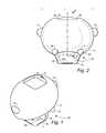
- FIG. 1is an elevational perspective view of a stackable container according to the present invention
- FIG. 2is a side elevational view of the container of FIG. 1 ;
- FIG. 3is an end elevational view of the container of FIG. 1 ;
- FIG. 4is a sectional elevational view of a cap portion of the container of FIG. 1 on line 4 - 4 in FIG. 2 ;
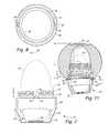
- FIG. 5is an elevational perspective view of a body portion of the container of FIG. 1 ;
- FIG. 6is a front elevational view of the body portion of FIG. 5 ;
- FIG. 7is a rear elevational view of the body portion of FIG. 5 ;
- FIG. 8is a top plan view of the body portion of FIG. 5 ;
- FIG. 9is a bottom view of the body portion of FIG. 5 ;
- FIG. 10is a detail view showing a stop and detent structure of the container of FIG. 1 ;
- FIG. 11is a fragmentary sectional detail view showing the body being positioned for threaded engagement with the cap;
- FIG. 12is a sectional elevational view showing the stackable container of FIG. 1 with the cap spaced from and in coaxial alignment with the body;
- FIG. 13is an elevational perspective view showing a stack of the containers of FIG. 1 .
- an exemplary container 10includes a body 12 and a threadingly connectible cap 14 , the cap being generally of enlarged ellipsoidal shape of length L, width W, and height H.
- An oppositely disposed pair of enlargements or handles 16project from the main ellipsoidal shape of the cap, the length L being exclusive of the handles.
- a plurality (in this case four) of feet 18project downwardly from an apron portion or skirt 20 of the cap 14 that extends downwardly a distance A about the body 12 as further described below.
- a depression 22is formed at the top of the cap 14 for receiving the bottom portion of a counterpart of the body 12 .
- Opposite upper extremities of the depression 22have inwardly oriented cap projections 24 for releasably holding the counterpart body as further described below.
- the body 12is formed including a threaded neck portion 26 having an integrally formed neck thread 27 , a cylindrical barrel portion 28 , and a base portion 30 that includes a floor wall 32 and outwardly and upwardly extending side walls 34 .
- the neck portion 26extends axially above the barrel portion by a neck length B as shown in FIG. 7 .
- the base portion 30is configured for registered engagement with the depression 22 that is formed in the cap 14 as described above, at least one pair of base projections 36 extending oppositely outwardly from the floor wall 32 , i.e, proximate bottom extremities of respective side walls 34 for snap engagement with the cap projections 24 that extend into the depression 22 as described above.
- the side walls 34can be considered to be overlapping outer extremities of the floor wall 32 , the base projections in the exemplary configuration being generally horizontally aligned with the floor wall.
- the floor wall 32is generally square, there being four of the side walls 34 , each of the side walls having a counterpart of the base projection 36 .
- the body 12can selectively have snap engagement with the cap in any of four orthogonal orientations.
- other preferably regular polygonal shapes of the base portionare possible with suitably configured forms of the cap depression 22 .
- configurations having an odd number of polygonal sides of the base portion 30are possible, preferably also incorporating an odd plurality of the cap projections 24 .
- the body 12is hollow, having an interior body cavity 38 for receiving at least a portion of an object 40 or objects to be stored.
- the object 40can project above the body 12 as shown in FIGS. 5 and 6 , the cap 14 having a vaulted interior object clearance surface 42 for clearing the object 40 .
- the objectcan be a consumable product such as lipstick or lip balm, in which case the product would typically completely fill the body cavity 38 , being preferably bonded thereto, useable portions of the product extending above the body as shown and described above.
- the container 10is preferably provided with a stop structure 43 that includes at least one body stop boss 44 that is formed on the body 12 for preventing excessive threaded tightening of the cap 14 onto the body 12 by abutting engagement with a cap stop boss 46 of the cap 14 as the threaded neck portion 26 of the body reaches fully threaded engagement with a complementary threaded portion 47 of the cap 14 .
- the boss 44have detentable engagement with a detent projection 48 of the cap 14 as described herein.
- the body stop boss 44is formed having a generally radially and axially extending body stop surface 50 that comes into abutting contact with a cap stop surface 52 of the cap stop boss 46 as best shown in FIG.
- the detent projection 48has an inclined first detent ramp surface 54 that is slidingly engaged by the boss 44 , the parts being momentarily slightly pried apart vertically as the boss approaches the full detented engagement. Also, a contact inclined boss ramp surface 56 is formed on the boss 44 opposite the body stop surface 50 for snap engagement with an inclined second detent ramp surface 58 of the detent projection 48 of the cap 14 .
- the inside of the skirt portion 20 of the cap 14forms a body clearance surface 60 for guiding the body 12 into alignment with the cap.
- the bodyis shown tilted out of alignment as the barrel portion 28 makes contact with bottom extremities of the skirt portion 20 as indicated at respective contact points 61 and 62 . As the body is moved upwardly into the cap, concentric alignment is achieved prior to the threaded engagement according to the present invention.
- FIG. 12shows the body 12 in concentric relation with the cap 14 , the clearance surface 60 of the cap 14 having a body clearance diameter C, and the barrel portion 28 of the body 12 having a body outside diameter D, with a resultant nominal radial clearance E between the barrel portion 28 and the skirt portion 20 , the skirt portion extending at least an axial skirt projection distance F below the cap stop boss 46 .
- the barrel portion 28need not be strictly circular, the body outside diameter being that which no part of the body 12 that will enter the skirt portion 20 projects beyond, the body being formed congruent with the body clearance diameter C sufficiently for the guiding into alignment described above in connection with FIG. 11 .
- the body outside diameter Dis approximately 1.12 inch (27.5 mm)
- the body clearance diameter Cis approximately 1.16 inch (29.5 mm)
- the radial clearance Ebeing nominally 0.02 inch (0.5 mm) and corresponding to 1.72 percent of the body outside diameter D. It is preferred that at this scale the radial clearance E be not less than 0.01 inch (0.25 mm), which corresponds to not less than 0.86 percent of the body clearance diameter C. More generally, it is preferred that the radial clearance E be not more than 2 percent of the body outside diameter D, more preferably, not more than 1 percent. Neither the body clearance surface 60 nor the outside of the body 12 such as at the contact points 61 and 62 need be strictly circular to achieve the above-described guiding into the threaded engagement, although such is preferred.
- the length L of the cap 14is approximately 2.2 inch (56 mm)
- the cap width Wis approximately 1.85 inch (47 mm)
- the height His approximately 1.7 inch (43 mm).
- the lengthis 2.2/1.85 ⁇ 100 or approximately 19 percent greater than the width. It is preferred that the length L be at least 15 percent greater than the width W for facilitating manipulation of the cap 14 , and for enhanced visual impact when plural containers 10 are stacked in various orientations.
- the length Lis 2.2/1.12 ⁇ 100 or approximately 100 percent greater than the body outside diameter D, it being preferred that the length L be at least 90 percent greater than the body outside diameter D.
- the width Wis 1.85/1.12 ⁇ 100 or approximately 154 percent greater than the body outside diameter D, it being preferred that the width W be at least 50 percent greater than the diameter D.
- FIG. 13shows a container stack 64 including four of the containers, the containers being individually designated 10 A, 10 B, 10 C, and 10 D, the container 10 C being rotated 90 degrees relative to the containers 10 A, 10 B, and 10 D. It will be understood that in addition to the various orientations permitted of individual ones of the containers 10 of the container stack 64 when each of the caps 14 are detented in the fully threaded condition on respective ones of the bodies 12 , any number of the caps 14 can be rotated out of respective detented conditions relative to a corresponding body 12 while maintaining an effective degree of threaded engagement.
- any desired relative angular orientation of particular ones of the caps 14 of the container stack 64is permitted without moving any of the caps 14 relative to its body 12 as much as 90 degrees.
- a body 12have a discernable orientation such as by having unique artwork on a particular side wall 34
- its cap 14can be rotated to any desired relative orientation in threaded engagement, provided the detented threaded engagement is greater than one revolution. In the exemplary configuration shown in the drawings, the detented engagement is in excess of one revolution.
- the cap 14can have a decorative shape simulating an animal face and/or body character, the handle portions 16 simulating ears and/or a nose and a tail, and the feet 18 simulating legs. Therefore, the spirit and scope of the appended claims should not necessarily be limited to the description of the preferred versions contained herein.
Landscapes
- Engineering & Computer Science (AREA)
- Mechanical Engineering (AREA)
- Ceramic Engineering (AREA)
- Closures For Containers (AREA)
Abstract
Description
Claims (10)
Priority Applications (1)
| Application Number | Priority Date | Filing Date | Title |
|---|---|---|---|
| US15/587,347US9850028B2 (en) | 2016-05-09 | 2017-05-04 | Stackable container having overhanging cap |
Applications Claiming Priority (3)
| Application Number | Priority Date | Filing Date | Title |
|---|---|---|---|
| US15/150,153US9981773B2 (en) | 2016-05-09 | 2016-05-09 | Stackable container having overhanging cap |
| US201615151124A | 2016-05-10 | 2016-05-10 | |
| US15/587,347US9850028B2 (en) | 2016-05-09 | 2017-05-04 | Stackable container having overhanging cap |
Related Parent Applications (1)
| Application Number | Title | Priority Date | Filing Date |
|---|---|---|---|
| US201615151124AContinuation | 2016-05-09 | 2016-05-10 |
Publications (2)
| Publication Number | Publication Date |
|---|---|
| US20170320624A1 US20170320624A1 (en) | 2017-11-09 |
| US9850028B2true US9850028B2 (en) | 2017-12-26 |
Family
ID=60242435
Family Applications (3)
| Application Number | Title | Priority Date | Filing Date |
|---|---|---|---|
| US15/150,153Active2036-08-19US9981773B2 (en) | 2016-05-09 | 2016-05-09 | Stackable container having overhanging cap |
| US15/587,347ActiveUS9850028B2 (en) | 2016-05-09 | 2017-05-04 | Stackable container having overhanging cap |
| US15/982,927Active2036-07-06US10647472B2 (en) | 2016-05-09 | 2018-05-17 | Stackable container having overhanging cap |
Family Applications Before (1)
| Application Number | Title | Priority Date | Filing Date |
|---|---|---|---|
| US15/150,153Active2036-08-19US9981773B2 (en) | 2016-05-09 | 2016-05-09 | Stackable container having overhanging cap |
Family Applications After (1)
| Application Number | Title | Priority Date | Filing Date |
|---|---|---|---|
| US15/982,927Active2036-07-06US10647472B2 (en) | 2016-05-09 | 2018-05-17 | Stackable container having overhanging cap |
Country Status (5)
| Country | Link |
|---|---|
| US (3) | US9981773B2 (en) |
| EP (1) | EP3455141B1 (en) |
| CN (1) | CN108602589A (en) |
| ES (1) | ES2776398T3 (en) |
| WO (1) | WO2017196677A1 (en) |
Cited By (2)
| Publication number | Priority date | Publication date | Assignee | Title |
|---|---|---|---|---|
| US10647472B2 (en) | 2016-05-09 | 2020-05-12 | Markwins Beauty Products, Inc. | Stackable container having overhanging cap |
| USD1087773S1 (en) | 2023-07-31 | 2025-08-12 | Airlite Plastics Co. | Container |
Families Citing this family (5)
| Publication number | Priority date | Publication date | Assignee | Title |
|---|---|---|---|---|
| USD868380S1 (en)* | 2016-09-14 | 2019-11-26 | Eos Products, Llc | Lip product container |
| USD968711S1 (en) | 2016-09-14 | 2022-11-01 | Eos Products, Llc | Lip product container |
| USD841252S1 (en) | 2016-09-14 | 2019-02-19 | Eos Products, Llc | Lip product container |
| ES2960315T3 (en)* | 2018-11-13 | 2024-03-04 | Oreal | Packaging device, in particular for cosmetic products and/or cosmetic accessories |
| IT201900007782A1 (en)* | 2019-05-31 | 2020-12-01 | Montefarmaco Otc S P A | DISPENSER CAP OF A SUBSTANCE IN A CONTAINER AND BOTTLE FITTED WITH THIS DISPENSER CAP |
Citations (33)
| Publication number | Priority date | Publication date | Assignee | Title |
|---|---|---|---|---|
| US2288349A (en)* | 1938-12-01 | 1942-06-30 | Anchor Cap & Closure Corp | Method of making closure caps |
| US3140007A (en) | 1962-09-07 | 1964-07-07 | Antaeus Lineal 1948 | Specimen container |
| US3369687A (en)* | 1966-05-02 | 1968-02-20 | Lewals Inc | Plastic container |
| US3819081A (en)* | 1971-03-12 | 1974-06-25 | Harre & Co A | Mailer for biological samples |
| US4230232A (en)* | 1978-03-18 | 1980-10-28 | Beecham Group Limited | Bottle with closure cap |
| US4483450A (en) | 1983-11-14 | 1984-11-20 | Gil Sanchez | Container and removable lid therefor |
| USD333976S (en) | 1990-07-19 | 1993-03-16 | Ferrero Ardennes S.A. | Container for confectionery products |
| USD374396S (en) | 1995-05-05 | 1996-10-08 | Albino Petrucci | Bottle |
| USD374395S (en) | 1993-12-22 | 1996-10-08 | Albino Petrucci | Bottle |
| USD374617S (en) | 1993-12-22 | 1996-10-15 | Albino Petrucci | Bottle |
| USD377757S (en) | 1995-03-30 | 1997-02-04 | Chesebrough-Pond's Usa Co., Division Of Conopco, Inc. | Stackable jar set |
| USD406053S (en) | 1997-09-18 | 1999-02-23 | Hee Tak Lau | Jewelry box |
| US20010022304A1 (en) | 1999-09-16 | 2001-09-20 | Howard Roche | Container |
| USD503018S1 (en) | 2003-11-25 | 2005-03-15 | Hawthorn Enterprise Co., Ltd. | Cosmetic container |
| USD503246S1 (en) | 2003-12-10 | 2005-03-22 | Hoyden Enterprise Co., Ltd. | Cosmetic container |
| USD517446S1 (en) | 2004-12-16 | 2006-03-21 | 3M Innovative Properties Company | Decorative article |
| USD517418S1 (en) | 2001-07-19 | 2006-03-21 | Henkel Kommanditgesellschaft Auf Aktien | Package |
| US20060072957A1 (en) | 2004-10-05 | 2006-04-06 | Min-Shih Wu | Structure of a cosmetics container |
| USD520409S1 (en) | 2004-12-16 | 2006-05-09 | 3M Innovative Properties Company | Decorative article |
| WO2006061612A1 (en) | 2004-12-11 | 2006-06-15 | Reckitt Benckiser N.V. | A stackable container |
| USD534457S1 (en) | 2005-10-25 | 2007-01-02 | 3M Innovative Properties Company | Decorative article |
| USD544399S1 (en) | 2005-10-25 | 2007-06-12 | 3M Innovative Properties Company | Decorative article |
| USD546061S1 (en) | 2005-07-14 | 2007-07-10 | Vpet International Group Co., Ltd. | Container |
| US20070237565A1 (en) | 2006-04-05 | 2007-10-11 | Coleman Thomas J | Replica cosmetic applicator |
| USD554432S1 (en) | 2006-07-12 | 2007-11-06 | Donna Roth | Bottle |
| US7726483B2 (en) | 2005-02-23 | 2010-06-01 | The Glad Products Company | Stacked containers |
| USD626425S1 (en) | 2009-12-11 | 2010-11-02 | Lam Samy Hak-Tang | Candy spray |
| US20140069884A1 (en)* | 2012-09-07 | 2014-03-13 | Owens-Brockway Glass Container Inc. | Container Having Primary and Secondary Support Surfaces |
| GB2506855A (en) | 2012-10-09 | 2014-04-16 | Chia-Meng Sung | Spherical cosmetics container |
| USD705075S1 (en) | 2013-01-29 | 2014-05-20 | Target Brands, Inc. | Package |
| USD726975S1 (en) | 2013-10-01 | 2015-04-14 | Societe Des Produits Nestle S.A. | Animal treat dispenser |
| USD733967S1 (en) | 2013-11-25 | 2015-07-07 | Oralabs, Inc. | Lip balm container |
| US9145231B2 (en) | 2006-02-09 | 2015-09-29 | Rubbermaid Incorporated | Storage container and container system |
Family Cites Families (15)
| Publication number | Priority date | Publication date | Assignee | Title |
|---|---|---|---|---|
| US1764452A (en)* | 1927-08-24 | 1930-06-17 | A J & K Company Inc | Container for lip sticks and the like |
| GB2017061B (en)* | 1978-03-18 | 1982-09-15 | Beecham Group Ltd | Screw capped bottle |
| FR2693883B1 (en)* | 1992-07-23 | 1994-09-09 | Cebal | Ball holder, this ball holder with a cover and its use. |
| US7819264B2 (en)* | 2003-12-03 | 2010-10-26 | Rexam Closure Systems Inc. | Child-resistant closure, container and package |
| US20060278601A1 (en)* | 2005-06-10 | 2006-12-14 | Owens-Illinois Closure Inc. | Plastic closure, closure and container package, and method of manufacture |
| WO2007092954A2 (en)* | 2006-02-09 | 2007-08-16 | Rubbermaid Incorporated | Storage container and container system |
| GB0803882D0 (en)* | 2008-03-03 | 2008-04-09 | Unilever Plc | Stackable cosmetic jar |
| US8967416B2 (en)* | 2009-01-09 | 2015-03-03 | Rubbermaid Incorporated | Food storage container and container system |
| US20150166219A1 (en)* | 2010-01-29 | 2015-06-18 | Integrity Products, Inc. | Perforable container cap |
| AT11968U1 (en)* | 2010-03-05 | 2011-08-15 | Dm Drogerie Markt Gmbh | COSMETICS CONTAINER SYSTEM |
| CN103653686B (en)* | 2012-09-07 | 2016-06-22 | 宋佳孟 | Quick pouring package container used for cosmetic |
| US20140263317A1 (en)* | 2013-03-15 | 2014-09-18 | Erich LINDER | Bottle Cap Replacement |
| CN203676394U (en)* | 2014-01-06 | 2014-07-02 | 珠海神采生物科技有限公司 | Visual lipstick box |
| CN204467304U (en)* | 2015-03-02 | 2015-07-15 | 曼秀雷敦(中国)药业有限公司 | A lipstick container for a spherical lipstick |
| US9981773B2 (en) | 2016-05-09 | 2018-05-29 | Markwins Beauty Products, Inc. | Stackable container having overhanging cap |
- 2016
- 2016-05-09USUS15/150,153patent/US9981773B2/enactiveActive
- 2017
- 2017-05-04USUS15/587,347patent/US9850028B2/enactiveActive
- 2017-05-05CNCN201780008296.3Apatent/CN108602589A/enactivePending
- 2017-05-05EPEP17724301.1Apatent/EP3455141B1/enactiveActive
- 2017-05-05ESES17724301Tpatent/ES2776398T3/enactiveActive
- 2017-05-05WOPCT/US2017/031416patent/WO2017196677A1/ennot_activeCeased
- 2018
- 2018-05-17USUS15/982,927patent/US10647472B2/enactiveActive
Patent Citations (36)
| Publication number | Priority date | Publication date | Assignee | Title |
|---|---|---|---|---|
| US2288349A (en)* | 1938-12-01 | 1942-06-30 | Anchor Cap & Closure Corp | Method of making closure caps |
| US3140007A (en) | 1962-09-07 | 1964-07-07 | Antaeus Lineal 1948 | Specimen container |
| US3369687A (en)* | 1966-05-02 | 1968-02-20 | Lewals Inc | Plastic container |
| US3819081A (en)* | 1971-03-12 | 1974-06-25 | Harre & Co A | Mailer for biological samples |
| US4230232A (en)* | 1978-03-18 | 1980-10-28 | Beecham Group Limited | Bottle with closure cap |
| US4483450A (en) | 1983-11-14 | 1984-11-20 | Gil Sanchez | Container and removable lid therefor |
| USD333976S (en) | 1990-07-19 | 1993-03-16 | Ferrero Ardennes S.A. | Container for confectionery products |
| USD334139S (en) | 1990-07-19 | 1993-03-23 | Ferrero Ardennes S.A. | Jar for confectionery products |
| USD342018S (en) | 1990-07-19 | 1993-12-07 | Ferrero Ardennes S.A. | Container for confectionery products |
| USD342019S (en) | 1990-07-19 | 1993-12-07 | Ferrero Ardennes S.A. | Container for confectionery products |
| USD374395S (en) | 1993-12-22 | 1996-10-08 | Albino Petrucci | Bottle |
| USD374617S (en) | 1993-12-22 | 1996-10-15 | Albino Petrucci | Bottle |
| USD377757S (en) | 1995-03-30 | 1997-02-04 | Chesebrough-Pond's Usa Co., Division Of Conopco, Inc. | Stackable jar set |
| USD374396S (en) | 1995-05-05 | 1996-10-08 | Albino Petrucci | Bottle |
| USD406053S (en) | 1997-09-18 | 1999-02-23 | Hee Tak Lau | Jewelry box |
| US20010022304A1 (en) | 1999-09-16 | 2001-09-20 | Howard Roche | Container |
| USD517418S1 (en) | 2001-07-19 | 2006-03-21 | Henkel Kommanditgesellschaft Auf Aktien | Package |
| USD503018S1 (en) | 2003-11-25 | 2005-03-15 | Hawthorn Enterprise Co., Ltd. | Cosmetic container |
| USD503246S1 (en) | 2003-12-10 | 2005-03-22 | Hoyden Enterprise Co., Ltd. | Cosmetic container |
| US20060072957A1 (en) | 2004-10-05 | 2006-04-06 | Min-Shih Wu | Structure of a cosmetics container |
| WO2006061612A1 (en) | 2004-12-11 | 2006-06-15 | Reckitt Benckiser N.V. | A stackable container |
| USD517446S1 (en) | 2004-12-16 | 2006-03-21 | 3M Innovative Properties Company | Decorative article |
| USD520409S1 (en) | 2004-12-16 | 2006-05-09 | 3M Innovative Properties Company | Decorative article |
| US7726483B2 (en) | 2005-02-23 | 2010-06-01 | The Glad Products Company | Stacked containers |
| USD546061S1 (en) | 2005-07-14 | 2007-07-10 | Vpet International Group Co., Ltd. | Container |
| USD544399S1 (en) | 2005-10-25 | 2007-06-12 | 3M Innovative Properties Company | Decorative article |
| USD534457S1 (en) | 2005-10-25 | 2007-01-02 | 3M Innovative Properties Company | Decorative article |
| US9145231B2 (en) | 2006-02-09 | 2015-09-29 | Rubbermaid Incorporated | Storage container and container system |
| US20070237565A1 (en) | 2006-04-05 | 2007-10-11 | Coleman Thomas J | Replica cosmetic applicator |
| USD554432S1 (en) | 2006-07-12 | 2007-11-06 | Donna Roth | Bottle |
| USD626425S1 (en) | 2009-12-11 | 2010-11-02 | Lam Samy Hak-Tang | Candy spray |
| US20140069884A1 (en)* | 2012-09-07 | 2014-03-13 | Owens-Brockway Glass Container Inc. | Container Having Primary and Secondary Support Surfaces |
| GB2506855A (en) | 2012-10-09 | 2014-04-16 | Chia-Meng Sung | Spherical cosmetics container |
| USD705075S1 (en) | 2013-01-29 | 2014-05-20 | Target Brands, Inc. | Package |
| USD726975S1 (en) | 2013-10-01 | 2015-04-14 | Societe Des Produits Nestle S.A. | Animal treat dispenser |
| USD733967S1 (en) | 2013-11-25 | 2015-07-07 | Oralabs, Inc. | Lip balm container |
Non-Patent Citations (3)
| Title |
|---|
| Disney-Pixar Inside Out Lip Balm Set, webpage, http://www.disneystore.com/small-toys-more-toys-disneybullpixar-inside-out-lip-balm-set/mp/1375027/1014307/; 3 pages. |
| Forever 21 Cat Lip Balm, webpage, http://www.polyvore.com/forever—21—cat—lip—balm/thing?context—id=4130274&context—type=lookbook&id=120759042, 1 page. |
| Homemade Natural Lip Gloss, webpage, http://ourbestbites.com/2013/01/homemade-natural-lip-gloss/; 19 pages. |
Cited By (2)
| Publication number | Priority date | Publication date | Assignee | Title |
|---|---|---|---|---|
| US10647472B2 (en) | 2016-05-09 | 2020-05-12 | Markwins Beauty Products, Inc. | Stackable container having overhanging cap |
| USD1087773S1 (en) | 2023-07-31 | 2025-08-12 | Airlite Plastics Co. | Container |
Also Published As
| Publication number | Publication date |
|---|---|
| US10647472B2 (en) | 2020-05-12 |
| US9981773B2 (en) | 2018-05-29 |
| US20170320622A1 (en) | 2017-11-09 |
| WO2017196677A1 (en) | 2017-11-16 |
| EP3455141A1 (en) | 2019-03-20 |
| CN108602589A (en) | 2018-09-28 |
| US20180265250A1 (en) | 2018-09-20 |
| US20170320624A1 (en) | 2017-11-09 |
| EP3455141B1 (en) | 2019-12-18 |
| ES2776398T3 (en) | 2020-07-30 |
Similar Documents
| Publication | Publication Date | Title |
|---|---|---|
| US10647472B2 (en) | Stackable container having overhanging cap | |
| US9278781B1 (en) | Stackable interlocking vessel | |
| CA2535913C (en) | Molded plastic container | |
| US12258170B2 (en) | Low depth dairy crate | |
| US20130105432A1 (en) | Container with Pour Spout | |
| US20150203238A1 (en) | Plastic container with fluted inner wall | |
| US20040245142A1 (en) | Multi-level stacking container | |
| US7726500B2 (en) | Plastic container with separately formed handle | |
| US20160007737A1 (en) | Bakery tray assembly | |
| US20170247142A1 (en) | Stackable container with spout | |
| MX2013014432A (en) | Nestable can tray. | |
| US9586736B2 (en) | Child resistant package | |
| US11420792B2 (en) | Handle, and container with handle | |
| US20060191938A1 (en) | Trash can with twist-lock lid | |
| US10669066B2 (en) | Nestable one quart half gallon and one gallon size paint cans for opening and closing them without the need of any tools | |
| US10633154B2 (en) | Combination cap and work support system | |
| CA158968S (en) | Closure | |
| US11505374B2 (en) | Child resistant maze container system with combination entry-exit groove | |
| US10723517B2 (en) | Stackable molded cap | |
| JP2018191980A (en) | Legged plate, rack configured by stacking the same in multiple layers and transportation cart | |
| USD804182S1 (en) | Stackable container | |
| EP2560891A1 (en) | A package | |
| CA2816035A1 (en) | Bin having handle on bottom wall | |
| US20150083716A1 (en) | Holding device | |
| GB2448111A (en) | Stacking lid |
Legal Events
| Date | Code | Title | Description |
|---|---|---|---|
| STCF | Information on status: patent grant | Free format text:PATENTED CASE | |
| AS | Assignment | Owner name:JPMORGAN CHASE BANK, N.A., ILLINOIS Free format text:SECURITY INTEREST;ASSIGNORS:MARKWINS BEAUTY PRODUCTS, INC.;PHYSICIANS FORMULA COSMETICS, INC.;MARKWINS BEAUTY BRANDS, INC.;REEL/FRAME:048737/0468 Effective date:20190328 | |
| MAFP | Maintenance fee payment | Free format text:PAYMENT OF MAINTENANCE FEE, 4TH YEAR, LARGE ENTITY (ORIGINAL EVENT CODE: M1551); ENTITY STATUS OF PATENT OWNER: LARGE ENTITY Year of fee payment:4 | |
| AS | Assignment | Owner name:PHYSICIANS FORMULA COSMETICS, INC., CALIFORNIA Free format text:RELEASE BY SECURED PARTY;ASSIGNOR:JPMORGAN CHASE BANK, N.A., AS ADMINISTRATIVE AGENT;REEL/FRAME:065053/0790 Effective date:20230926 Owner name:MARKWINS BEAUTY PRODUCTS, INC., CALIFORNIA Free format text:RELEASE BY SECURED PARTY;ASSIGNOR:JPMORGAN CHASE BANK, N.A., AS ADMINISTRATIVE AGENT;REEL/FRAME:065053/0790 Effective date:20230926 Owner name:MARKWINS BEAUTY BRANDS, INC., CALIFORNIA Free format text:RELEASE BY SECURED PARTY;ASSIGNOR:JPMORGAN CHASE BANK, N.A., AS ADMINISTRATIVE AGENT;REEL/FRAME:065053/0790 Effective date:20230926 | |
| AS | Assignment | Owner name:CITIBANK, N.A., AS ADMINISTRATIVE AGENT, TEXAS Free format text:SECURITY INTEREST;ASSIGNORS:MARKWINS BEAUTY BRANDS, INC.;MARKWINS BEAUTY PRODUCTS, INC.;REEL/FRAME:065090/0423 Effective date:20230926 | |
| FEPP | Fee payment procedure | Free format text:7.5 YR SURCHARGE - LATE PMT W/IN 6 MO, LARGE ENTITY (ORIGINAL EVENT CODE: M1555); ENTITY STATUS OF PATENT OWNER: LARGE ENTITY | |
| MAFP | Maintenance fee payment | Free format text:PAYMENT OF MAINTENANCE FEE, 8TH YEAR, LARGE ENTITY (ORIGINAL EVENT CODE: M1552); ENTITY STATUS OF PATENT OWNER: LARGE ENTITY Year of fee payment:8 |