US9849326B2 - Magnetic weight selector - Google Patents
Magnetic weight selectorDownload PDFInfo
- Publication number
- US9849326B2 US9849326B2US14/642,282US201514642282AUS9849326B2US 9849326 B2US9849326 B2US 9849326B2US 201514642282 AUS201514642282 AUS 201514642282AUS 9849326 B2US9849326 B2US 9849326B2
- Authority
- US
- United States
- Prior art keywords
- locking member
- plate
- weight
- exercise machine
- weight plate
- Prior art date
- Legal status (The legal status is an assumption and is not a legal conclusion. Google has not performed a legal analysis and makes no representation as to the accuracy of the status listed.)
- Active
Links
Images


Classifications
- A—HUMAN NECESSITIES
- A63—SPORTS; GAMES; AMUSEMENTS
- A63B—APPARATUS FOR PHYSICAL TRAINING, GYMNASTICS, SWIMMING, CLIMBING, OR FENCING; BALL GAMES; TRAINING EQUIPMENT
- A63B21/00—Exercising apparatus for developing or strengthening the muscles or joints of the body by working against a counterforce, with or without measuring devices
- A63B21/06—User-manipulated weights
- A63B21/062—User-manipulated weights including guide for vertical or non-vertical weights or array of weights to move against gravity forces
- A63B21/0626—User-manipulated weights including guide for vertical or non-vertical weights or array of weights to move against gravity forces with substantially vertical guiding means
- A63B21/0628—User-manipulated weights including guide for vertical or non-vertical weights or array of weights to move against gravity forces with substantially vertical guiding means for vertical array of weights
- A63B21/063—Weight selecting means
- A—HUMAN NECESSITIES
- A63—SPORTS; GAMES; AMUSEMENTS
- A63B—APPARATUS FOR PHYSICAL TRAINING, GYMNASTICS, SWIMMING, CLIMBING, OR FENCING; BALL GAMES; TRAINING EQUIPMENT
- A63B24/00—Electric or electronic controls for exercising apparatus of preceding groups; Controlling or monitoring of exercises, sportive games, training or athletic performances
- A63B24/0087—Electric or electronic controls for exercising apparatus of groups A63B21/00 - A63B23/00, e.g. controlling load
- A—HUMAN NECESSITIES
- A63—SPORTS; GAMES; AMUSEMENTS
- A63B—APPARATUS FOR PHYSICAL TRAINING, GYMNASTICS, SWIMMING, CLIMBING, OR FENCING; BALL GAMES; TRAINING EQUIPMENT
- A63B2209/00—Characteristics of used materials
- A63B2209/08—Characteristics of used materials magnetic
Definitions
- Aerobic exercisegenerally refers to activities that substantially increase the heart rate and respiration of the exerciser for an extended period of time. This type of exercise is generally directed to enhancing cardiovascular performance. Such exercise usually includes low or moderate resistance to the movement of the individual.
- aerobic exerciseincludes activities such as walking, running, jogging, swimming or bicycling for extended distances and extended periods of time.
- Anaerobic exercisegenerally refers to exercise that strengthens skeletal muscles and usually involves the flexing or contraction of targeted muscles through significant exertion during a relatively short period of time and/or through a relatively small number of repetitions.
- anaerobic exerciseincludes activities such as weight training, push-ups, sit-ups, pull-ups, or a series of short sprints.
- a muscle groupis contracted against resistance.
- the contraction of some muscle groupsproduces a pushing motion, while the contraction of other muscle groups produces a pulling motion.
- a cable machineis a popular piece of exercise equipment for building those muscle groups that produce pulling motions.
- a cable machineoften includes a cable with a handle connected to a first end and a resistance mechanism connected to a second end.
- the resistance mechanismis an selectable set of weights.
- a midsection of the cableis supported with at least one pulley.
- a userpulls on the handle with a force sufficient to overcome the force of the resistance mechanism.
- the pulley or pulleysdirect the movement of the cable and carry a portion of the resistance mechanism's load.
- an exercise machinehas an automatic and programmable resistance selection apparatus with vertically aligned weights that are selectable by rotatably engaging a lift pin to select each weight stack.
- the exercise machinefurther includes a control module from which the number of weights to be lifted can be ordered by the user. Alternatively, the number of weights being lifted may be programmed from a remote location.
- Other types of cable exercise machinesare described in U.S. Pat. No. 7,473,211 issued to Byung-don Lee and U.S. Pat. No. 6,117,049 issued to John C. Lowe.
- a weight plate for use in a weight stack of an exercise machineincludes a locking member moveably attached to the weight plate.
- the locking memberhas a interlocked position and a unlocked position.
- the weight platefurther includes an interlocking magnet attached to the weight plate to retain the locking member in the interlocked position and an unlocking magnet attached to the weight plate to retain the locking member in the unlocked position.
- the weight platemay further include a cavity defined by the at least one plate, wherein the locking member is at least partially disposed within the cavity.
- the interlocking magnetis positioned proximate the first wall
- the unlocking magnetis positioned proximate the second wall.
- the cavitymay be lined with a non-magnetic material.
- the interlocking magnet and the unlocking magnetmay abut a non-magnetic material.
- the interlocking magnet and the unlocking magnetmay be encased in a non-magnetic material.
- the locking memberis connected to the weight plate via a pivot shaft.
- a lift openingmay be formed in the weight plate
- the interlocking magnetis positioned on the at least one plate on a first side of the lift opening.
- the pivot shaftis positioned on the at least one plate on a second side of the lift opening.
- the weight platemay include further a plurality of guide openings formed in the weight plate.
- an exercise machinein another preferred embodiment, includes a frame and a weight assembly with multiple plates moveably disposed along a vertical length of the frame.
- the exercise machinealso includes a lifting member selectively engaged with the weight assembly, and the multiple plates each include at least one lift opening to receive the lifting member.
- the lifting memberis oriented transverse to a plate length and to travel in a transverse direction with respect to the plate length.
- the exercise machineincludes a locking member associated with at least one plate of the multiple plates, and a selector having a interlocked position and a unlocked position. When the selector is in the interlocked position, the locking member is interlocked with the lifting member. When the selector is in the unlocked position, the locking member is disengaged from the lifting member.
- the locking memberis connected to the at least one plate with a pivot shaft.
- the locking memberhas an interlocking region that resides in a notch formed in the lifting member.
- the selectorcomprises a linear actuator to cause the locking member to change positions.
- the selectorfurther comprises a catching surface to catch an exposed end of the locking member such that the locking member pivots into a different position when the linear actuator is actuated.
- the catching surfaceis shaped to free the exposed end of the locking member to move with respect to the catching surface along the length of the frame.
- the catching surfaceis incorporated on an actuator lever that is pivotally movable when the linear actuator is actuated.
- the exercise machineincludes a control module that includes a weight selecting input mechanism in communication with a processor that causes the selector to position the locking member.
- multiple selectorsmovable to position multiple locking members connected to multiple plates.
- the exercise machineincludes a magnet positioned to retain the locking member in the interlocked position.
- the exercise machineincludes a magnet positioned to retain the locking member in the unlocked position.
- the frameincludes guide posts that are partially disposed within guide openings that are positioned on opposing sides of the multiple plates, the guide posts being oriented to guide the multiple plates as the multiple plates move along the length of the frame.
- an exercise machineincludes a frame.
- the exercise machineincludes a weight assembly comprising multiple plates moveably disposed along a vertical length of the frame with a lifting member.
- the multiple platescomprising lift openings that receive the lifting member.
- the lifting memberbeing oriented transverse to a plate length and to travel in a transverse direction with respect to the plate length.
- At least one of the multiple platesincludes a locking member associated with at least one plate.
- the exercise machineincludes a selector that has an ability to cause the locking member to change from an interlocked position where the locking member is interlocked with the lifting member and an unlocked position where the locking member is disengaged from the lifting member.
- the locking memberis connected to the at least one plate with a pivot shaft.
- the locking memberhas an interlocking region that resides in a notch formed in the lifting member.
- the selectorcomprises a linear actuator causes the locking member to change positions.
- the selectorfurther comprises a catching surface that catches an exposed end of the locking member such that the locking member pivots into a different position when the linear actuator is actuated.
- the catching surfaceis shaped to free the exposed end of the locking member to move with respect to the catching surface along the length of the frame.
- the exercise machineincludes a control module that includes a weight selecting input mechanism in communication with a processor that causes the selector to position the locking member.
- multiple selectorsmovable to position multiple locking members connected to multiple subsets of the multiple plates.
- the exercise machineincludes a magnet positioned to retain the locking member in the interlocked position.
- an exercise machinewith a frame.
- the exercise machinehaving a weight assembly comprising multiple plates moveably disposed along a vertical length of the frame with a lifting member.
- the multiple platescomprising lift openings that receive the lifting member.
- the lifting memberbeing oriented transverse to a plate length and to travel in a transverse direction with respect to the plate length.
- the frameincludes guide posts that are partially disposed within guide openings that are positioned on opposing sides of the multiple plates, the guide posts being oriented to guide the multiple plates as they move along the length of the frame.
- the exercise machineincludes a selector that has an ability to cause the locking member to change from an interlocked position where the locking member is interlocked with the lifting member and an unlocked position where the locking member is disengaged from the lifting member.
- the exercise machineincludes a unlocking magnet is positioned to retain the locking member in the unlocked position.
- the locking memberhas an interlocking region that resides in a notch formed in the lifting member.
- the selectorcomprises a linear actuator causes the locking member to change positions.
- the selectorfurther comprises a catching surface catches an exposed end of the locking member such that the locking member pivots into a different position in response to movement of the linear actuator.
- the catching surfaceis incorporated on an actuator lever that is pivotally movable in response to movement of the linear actuator.
- an exercise machineincludes a frame.
- the multiple plateseach include at least one lift opening positioned to receive the lifting member.
- the exercise machineincludes a locking member associated with at least one plate of the multiple plates.
- the exercise machineincludes a interlocking magnet is positioned to retain the locking member in a interlocked position.
- the locking memberis connected to the at least one plate with a pivot shaft.
- the frameincludes guide posts that are partially disposed within guide openings that are positioned on opposing sides of the multiple plates, the guide posts being oriented to guide the multiple plates as the multiple plates move along the vertical length of the frame.
- the interlocking magnet and unlocking magnetare incorporated into the at least one plate of the multiple plates.
- the locking memberis partially disposed within a cavity formed in the plate.
- the cavitycomprises an entrance through which the exposed end of the locking member protrudes.
- the cavitycomprises an opening formed in the underside of the plate.
- the cavitycomprises a first wall located to position the locking member in the interlocked position.
- the interlocking magnetis positioned adjacent the first wall and the cavity.
- the cavitycomprises a second wall located to position the locking member in the unlocked position.
- the unlocking magnetis positioned adjacent the second wall and the cavity.
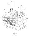
- FIG. 2illustrates a perspective view of an example of a weight assembly in accordance with the present disclosure.
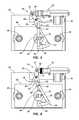
- FIG. 3illustrates a top view of the weight assembly of FIG. 2 with a locking member interlocked with a lifting member.
- FIG. 4illustrates a top view of the weight assembly of FIG. 2 with a locking member disengaged with a lifting member.
- FIG. 5Aillustrates a perspective view of an underside of the weight plate of FIG. 2 .
- FIG. 5Billustrates a perspective view of an underside of the weight plate of FIG. 2 .
- FIG. 6Aillustrates a front view of the lifting member of FIG. 2 .
- FIG. 6Billustrates a front view of an alternative example of a lifting member in accordance with the present disclosure.
- FIG. 7illustrates a top view of an alternative example of a weight assembly in accordance with the present disclosure.
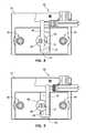
- FIG. 8illustrates a top view of an alternative example of a weight assembly with a locking member interlocked with a lifting member in accordance with the present disclosure.
- FIG. 9illustrates a top view of the weight assembly of FIG. 8 with the locking member disengaged from the lifting member.
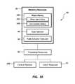
- FIG. 10illustrates block diagram of an example of a selecting system in accordance with the present disclosure.
- FIG. 11illustrates a diagram of an example of a selecting system in accordance with the present disclosure.
- FIG. 12illustrates a diagram of an example of a selecting system in accordance with the present disclosure.
- FIG. 13illustrates a diagram of an example of a selecting system in accordance with the present disclosure.
- weight assembliesinvolve a removable pin that a user inserts through an opening in a weight plate. As the user inserts the removable pin through the opening, a distal end of the pin is inserted into a lifting member that has another opening aligned with the opening formed in the weight plate. As a result, the removable pin interlocks the selected weight plate with the lifting member.
- the lifting memberis connected to an end of a pull cable, and a mid-portion of the pull cable is supported on a frame of the machine, often with a pulley.
- the pulley or other routing mechanism of the pull exercise machinedirects the forces exerted by the user to raise the lifting member in an upward direction.
- the interlocked weight plate plus any weight plates supported by the interlocked weight platemoves with the lifting member.
- the weight of the weight plate and any other weight plates supported by the interlocked weight plateprovide resistance to the user's pull.
- the principles described in the present disclosurespare the user from having to manually insert the pin. Further, when the user desires to switch the weight, the principles described herein spare the user from having to remove the removable pin manually and reinsert it.
- the present disclosuredescribes an automated weight plate selector that can automatically interlock a locking member with a lifting member of the pull exercise machine without the user having to make manual adjustments.
- the locking membermay be integrated directly into the weight plate.
- the locking memberis pivotally attached to the weight plate with a pivot shaft. As the locking member rotates about the pivot shaft, a region of the locking member is rotated into or away from the lifting member. In such examples, a notch is formed in the lifting member and the locking member can be moved into and away from the notch. When a region of the locking member resides within the notch, the locking member interlocks the weight plate with the lifting member. As a result, when the lifting member moves in response to a pull from a user, the weight plate and any weight plates supported by the interlocked weight plate move with the lifting member.
- a selectorcan control when the locking member is pivoted into the notch.
- the selectorincludes a linear actuator that is connected to an actuator lever. As the linear actuator moves a push/pull rod forward and backward with respect to the linear actuator, the rod causes the actuator lever to pivot into a different position.
- the actuator leveris shaped to form a catching surface that catches an exposed end of the locking member such that the locking member pivots into a different position in response to movement of the linear actuator.
- alignedgenerally means parallel, substantially parallel, or forming an angle of less than 35 degrees.
- transversegenerally means perpendicular, substantially perpendicular, or forming an angle between 55 and 125 degrees.
- FIG. 1depicts a cable exercise machine 10 with a frame 12 that supports a cable 14 .
- a weight assembly 16is attached to a lifting end 18 of the cable 14 and a handle 26 is connected to a pull end 22 of the cable 14 .
- the cable 14is supported with at least one pulley 24 that causes the pull forces exerted by the user on the pull end 22 of the cable 14 to raise the lifting end 18 of the cable 14 .
- the pull end 22 of the cable 14may be equipped with a replaceable handle 26 .
- the usercan switch between different types of handles with different grips, widths, and/or angles to target the muscle groups desired to be worked by the user.
- a cable connector located at the pull end 22may include a loop to which the replaceable handle 26 can be secured.
- a stopperis attached to the pull end 22 of the cable 14 .
- the stoppercan include a large enough cross sectional thickness to stop the pull end 22 from being pulled into a pulley 24 or another feature of the cable exercise machine 10 that directs the movement of the cable 14 .
- the weight assembly 16may include multiple weight plates 32 that are arranged to be lifted with the lifting end 18 of the cable 14 when interlocked with a lifting member 34 connected to the lifting end 18 .
- One or more selectors 36may be incorporated into the cable exercise machine 10 to cause a plate to interlock with the lifting member 34 .
- a selector 36is associated with each plate in the weight assembly 16 .
- a selector 36is associated with a single weight plate or a subset of the weight plates 32 .
- FIGS. 2-6Aillustrates different views of an example of the weight assembly 16 in accordance with the present disclosure.
- FIG. 3illustrates a top view of the weight assembly 16 with a locking member 38 interlocked with a lifting member 34 .
- FIG. 4illustrates a top view of the weight assembly 16 with the locking member 38 disengaged from the lifting member 34 .
- FIGS. 5A and 5Billustrate perspective views of the underside of the weight plates 32 .
- FIG. 6Aillustrates a front view the lifting member 34 in accordance with the present disclosure.
- a first guide post 40 and a second guide post 42direct the movement of the multiple weight plates 32 in a vertical direction.
- the guide posts 40 , 42may be rigidly attached to a base of the cable exercise machine 10 and a top of the machine's frame 12 .
- the first guide post 40is shaped to be inserted into a first guide opening 44 formed in the weight plates 32
- the second guide post 42is shaped to be inserted into a second guide opening 46 also formed in the weight plates 32 .
- a lift opening 48is also formed in the weight plates 32 that is positioned and sized to receive the lifting member 34 . In the illustrated example, the lift openings 48 are formed in the center of the weight plates 32 .
- the illustrated examplehas been described with reference to specific locations for the guide openings 44 , 46 and the lift openings 48 , these openings may be formed in any appropriate location of the weight plates 32 .
- at least one of the guide openings 44 , 46 and lift opening 48are grooves formed an edge of the weight plates 32 .
- the lifting member 34includes multiple notches 50 that are sized to receive an interlocking region 52 of the locking member 38 .
- the locking members 38are attached to the weight plates 32 with a pivot shaft 54 .
- the locking members 38may rotate about the pivot shaft 54 within a range.
- the locking member 38is in an interlocked position 56 with the interlocking region 52 being disposed within notch 50 formed in the lifting member 34 .
- an interlocking magnet 58may be incorporated into the weight plates 32 to apply a magnetic force to the locking member 38 to aid in retaining the locking member 38 in the interlocked position 56 .
- the locking member 38is in an unlocked position 60 .
- the interlocking region 52is outside of the notch 50 .
- An unlocking magnet 62may also be incorporated into the weight plate 32 and positioned to apply a magnetic force to retain the locking member 38 in the unlocked position 60 .
- the locking member 38When the locking member 38 is in the interlocked position 56 , the locking member 38 is interlocked with the lifting member 34 and causes the weight plate 32 to move with the lifting member 34 in response to a pull force exerted by a user along the cable 14 .
- the locking member 38when the locking member 38 is in the unlocked position 60 , the locking member 38 is disengaged from the lifting member 34 . Consequently, as the lifting member 34 moves in response to a pull force exerted by the user, the weight plate 32 may not move with the lifting member 34 . In some examples, the weight plate 32 may still move with the lifting member 34 even when the locking member 38 is in the unlocked position 60 .
- Such examplesmay include when the weight plate 32 is interlocked or supported by another weight plate. For instance, when a subjacent weight plate located underneath the unlocked weight plate is interlocked with the lifting member 34 , the unlocked weight plate may move with the interlocked, subjacent weight plate.
- the locking member 38may be caused to pivot about the pivot shaft 54 at an exposed end 64 that protrudes beyond an edge 66 of the weight plate 32 .
- the exposed end 64may be pushed by an actuator lever 68 that is moved by a linear actuator 70 .
- the actuator lever 68may be connected to the linear actuator 70 at an actuator end 72 and may rotate about a fulcrum 74 attached to a selector plate 76 that supports at least some of the components of the selector 36 .
- the rotation about the fulcrum 74causes a contact end 78 of the actuator lever 68 to catch the exposed end 64 of the locking member 38 with a catching surface 80 formed on the contact end 78 .
- the catching surface 80may be shaped to push the locking member 38 into the unlocked position 60 when the linear actuator 70 extends a push/pull rod 82 . Further, the catching surface 80 may also be shaped to push the locking member 38 into the interlocked position 56 when the linear actuator 70 retracts the push/pull rod 82 .
- linear actuator 70Any appropriate type of linear actuator 70 may be used to cause the locking member 38 to interlock or move away from the lifting member 34 .
- an electro-mechanical actuatorsuch as a screw type actuator, wheel and axle type actuator, a cam type actuator, or another type of electro-mechanical actuator may be used in accordance with the principles described in the present disclosure.
- hydraulic type actuators, pneumatic type actuators, piezoelectric type actuators, magnetostrictive type actuators, solenoids, other type actuators, or combinations thereofmay be used in accordance with the principles described herein.
- another type of actuatorother than a linear type actuator, may be used to cause the locking member 38 to move from the interlocked position 56 to the unlocked position 60 and vice versa.
- the locking member 38may be partially disposed within a cavity 61 formed in the weight plate 32 .
- the cavity 61may be fully enclosed with the exception of an entrance 63 where the exposed end 64 protrudes out of the weight plate 32 .
- the cavity 61is open on the underside of the weight plate 32 as illustrated in FIGS. 5A and 5B .
- the cavity 61may include walls that limit the locking member's range of pivot motion.
- the walls of the cavity 61may provide a location to secure the interlocking magnet 58 and the unlocking magnet 62 .
- the magnets 58 , 62may be located above or below the locking member 38 as well when the locking member 38 is in either of the positions.
- the locking member 38is attached below the weight plate 32 or another location outside of a cavity 61 of the weight plate 32 .
- the lifting member 34includes multiple notches 50 formed in a notch side 84 of the lifting member 34 .
- the notch depth 86is sufficiently deep to retain the locking member 38 when it is in the interlocked position 56 .
- the lifting member 34may be shaped to cause the load of the interlocked weight plate and other weight plates that are supported by the interlocked weight plate to spread to a support side 88 of the lifting member 34 .
- the support side 88has a sufficient thickness to support the defected loads. In some examples, all of the load from the interlocked plate and the plates situated above the interlocked plate are transferred into the lifting member 34 at a single notch.
- multiple locking members 38are interlocked with the lifting member 34 at the same time.
- the load of the raised weight platesare distributed over multiple notches 50 .
- the selectors 36may cause each of the locking members 38 associated with the top four plates in the weight assembly 16 to interlock with the lifting member 34 .
- the top four weight platesare raised, a load associated with each ten pound plate is distributed across the four notches associated with each of the interlocked weight plates.
- the selectors 36may respond to the command to interlock forty pounds by interlocking a single locking member associated with the fourth plate from the top of the weight stack. In such an example, the entire load is transferred to the lifting member 34 at the notch 50 associated with just the interlocked plate. In yet other examples, the selectors 36 may respond to the command to interlock forty pounds by interlocking just two of the locking members 38 associated with just two of the top four weight plates.
- each selector 36can be dedicated to interlocking and unlocking a single weight plate with the locking member 38 .
- the selectors 36may be rigidly fixed in place such that the selectors 36 remain in a stationary position with respect to the machine's frame 12 as the interlocked weight plate moves with the lifting member 34 .
- the selectors 36may remain stationary with respect to the frame 12 as the interlocked weight plates move, but the selectors 36 have an ability to move vertically so that they can position the locking members 38 of more than one weight plate.
- the catching surfaces 80are shaped to free the exposed end 64 of the locking member 38 to move with respect to the catching surface 80 along the length of the frame 12 .
- Such a catching surface 80may be free of overhangs, ledges, or other types of protrusions that can catch the exposed ends 64 of the locking member 38 as the weight plates 32 travel with the lifting member 34 .
- the catching surface 80may form a depression 81 shaped by a first prong 83 and a second prong 85 .
- the first prong 83may push the exposed end 64 of the locking member 38 such that the locking member 38 transitions into the unlocked position 60 as the linear actuator 70 extends the push/pull rod 82 .
- the second prong 85may push the exposed end 64 of the locking member 38 such that the locking member 38 transitions into the interlocked position 56 as the linear actuator 70 retracts the push/pull rod 82 .
- Both the first and second prongs 83 , 85may catch the exposed end 64 of the locking member 38 as the linear actuator 70 moves the actuator lever 68 in a direction that is transverse the lifting member's lifting direction.
- the exposed end 64may reside in the depression 81 when the weight plate 32 is in a resting position regardless of whether the locking member 38 is in the interlocked position 56 or the unlocked position 60 .
- the depression 81is free of prongs, overhangs, protrusions, or other types of features that can catch the exposed end 64 as the weight plates 32 move with the lifting member 34 .
- FIG. 6Billustrates a front view of an example of a lifting member 34 in accordance with the present disclosure.
- the lifting member 34includes notches 50 on first side 108 and a second side 110 of the lifting member 34 . Having the notches 50 on more than one side of the lifting member 34 distributes the loads from the interlocked plates to an additional side.
- the notches 50may be formed in the lifting member 34 in more than two sides.
- the selectors 36may be arranged such that some selectors 36 are on different sides of the cable exercise machine 10 .
- a single direction of the push/pull rod 82causes some of the locking members 38 to move into the interlocked position 56 where the same direction causes other locking members to move into the unlocked position 60 .
- the extension of the push/pull rod 82may cause locking members, which are configured to interlock with notches 50 on the first side 108 of the lifting member 34 , to move into the interlocked position 56 . But, for those locking members 38 that are configured to interlock with notches on the second side 110 of the lifting member 34 , the extension of the push/pull rod 82 may cause the locking members 38 to move into the unlocked position 60 .
- the lifting member 34is constructed to interlock with the locking members 38 through a different arrangement than through a notch.
- protrusions, ledges, hooks, or other featurescan be integrated into or attached to the lifting member 34 to provide a mechanism for the locking members 38 to interlock with the lifting member 34 .
- FIG. 7illustrates a top view of an example of a weight assembly 16 in accordance with the present disclosure.
- the push/pull rod 82 of the linear actuator 70directly contacts the locking member 38 .
- the head 112 of the push/pull rod 82may push the locking member 38 into a different position as the push/pull rod 82 extends.
- the head 112includes a magnetically conductive material that is capable pulling the locking member 38 back into its original position as the push/pull rod 82 retracts.
- the interlocking magnet 58 and the unlocking magnet 62may be positioned between the lift opening 48 and the linear actuator 70 .
- the interlocking and unlocking magnets 58 , 62may be positioned in any appropriate location of the weight plates 32 as long as the appropriate magnet may be proximate the locking member 38 when the locking member 38 is in the corresponding position.
- FIGS. 8 and 9illustrates a top view of an alternative example of a weight assembly 16 in accordance with the present disclosure.
- the locking member 38is rigidly attached to the linear actuator 70 , and the locking member 38 does not pivot about a pivot shaft. Rather, the extension of the push/pull rod 82 translates the locking member 38 into a notch 50 of the lifting member 34 . Likewise, a retraction of the push/pull rod 82 translates the locking member 38 out of the notch 50 thereby disengaging the locking member 38 from the lifting member 34 .
- FIG. 10illustrates block diagram of an example of a selecting system 90 in accordance with the present disclosure.
- the selecting system 90may include a combination of hardware and program instructions for executing the functions of the selecting system 90 .
- the selecting system 90includes processing resources 92 that are in communication with memory resources 94 .
- Processing resources 92include at least one processor and other resources used to process programmed instructions.
- the memory resources 94represent generally any memory capable of storing data such as programmed instructions or data structures used by the selecting system 90 .
- the programmed instructions shown stored in the memory resources 94include a plate selector 96 and a plate actuator executor 98 .
- the data structures shown stored in the memory resources 94include a plate library 100 that includes a record of plate identifiers 102 and a connection status 104 for each plate.
- the memory resources 94include a computer readable storage medium that contains computer readable program code to cause tasks to be executed by the processing resources 92 .
- the computer readable storage mediummay be a tangible and/or non-transitory storage medium.
- the computer readable storage mediummay be any appropriate storage medium that is not a transmission storage medium.
- a non-exhaustive list of computer readable storage medium typesincludes non-volatile memory, volatile memory, random access memory, write only memory, flash memory, electrically erasable program read only memory, magnetic based memory, other types of memory, or combinations thereof.
- the plate library 100may include a record of plate identifiers 102 for each of the plates in the weight assembly 16 . Such identifiers may be an alphanumeric symbol, a binary sequence, another type of symbol, or combinations thereof. For each of the identified weight plates, the plate library 100 may maintain an active record the connection status 104 of each of the weight plates 32 .
- the plate selector 96represents programmed instructions that, when executed, cause the processing resources 92 to select the weight plates 32 to be interlocked with the lifting member 34 . For example, in response to receiving a command from the user through a control module 106 the plate selector 96 consults the plate library 100 to determine which of the weight plates 32 is already interlocked with the lifting member 34 . If the command is to interlock forty pounds to the lifting assembly and each weight plate 32 is approximately ten pounds, the plate selector 96 can determine if forty pounds is already interlocked to the lifting member 34 by consulting the plate library 100 .
- plate selector 96may determine that the selectors 36 associated with the third and fourth plate from the top of the weight assembly 16 should be executed to extend the push/pull rods 82 .
- the control module 106may be integrated directly into the cable exercise machine 10 . However, in other examples, the control module 106 is incorporated into a device at a remote location. Such a device may include a phone, a laptop, a desktop, an electronic tablet, a computer, another type of remote location, or combinations thereof.
- the plate actuator executor 98represents programmed instructions that, when executed, cause the processing resources 92 to actuate the linear actuators 70 associated with the selected weight plates.
- the actuatoris an electro-mechanical actuator
- an electrical signalmay be sent to the linear actuators 70 to extend the appropriate locking members to interlock with the third and fourth plate.
- the plate library 100may indicate that the first six plates of the weight assembly 16 are currently interlocked with the lifting member 34 .
- the plate selector 96may determine that the selectors 36 associated with the fifth and sixth plate from the top of the weight assembly 16 should be executed to retract the push/pull rods 82 .
- the plate actuator executor 98may send the appropriate signal to the linear actuators 70 to retract the push/pull rods 82 to disengage the locking members 38 from the fifth and sixth weight plates.
- the memory resources 94may be part of an installation package.
- the programmed instructions of the memory resources 94may be downloaded from the installation package's source, such as a portable medium, a server, a remote network location, another location, or combinations thereof.
- Portable memory mediathat are compatible with the principles described herein include DVDs, CDs, flash memory, portable disks, magnetic disks, optical disks, other forms of portable memory, or combinations thereof.
- the program instructionsare already installed.
- the memory resources 94can include integrated memory such as a hard drive, a solid state hard drive, or the like.
- the processing resources 92 and the memory resources 94are located within the cable exercise machine 10 .
- the memory resources 94may be part of the machine's main memory, caches, registers, non-volatile memory, or elsewhere in the machine's memory hierarchy.
- the memory resources 94may be in communication with the processing resources 92 over a network.
- the data structures, such as the libraries,may be accessed from a remote location over a network connection while the programmed instructions are located locally.
- the selecting system 90may be implemented on the cable exercise machine; a user device; a mobile device; a phone; an electronic tablet; a wearable computing device; a head mounted device; a server; a collection of servers; a networked device; a user interface incorporated into a car, truck, plane, boat, bus, another type of automobile; a watch; or combinations thereof.
- Such an implementationmay occur through input mechanisms, such as push buttons, touch screen buttons, voice commands, dials, levers, other types of input mechanisms, or combinations thereof.
- the control module 106may be integrated into the cable exercise machine 10 .
- the control module 106may include a display screen that indicates the current conditions of the cable exercise machine 10 .
- the control module 106may indicate the current amount of weight that is interlocked with the lifting member 34 .
- the control module 106may indicate an amount of force exerted by the user during the latest pull, a number of calories burned by the user, a physiological parameter such as a heart rate, a breathing rate, an oxygen consumption rate, another of parameter, or combinations thereof.
- the control module 106may include an input mechanism that allows the user to send commands for the amount of weight to interlock with the lifting member 34 .
- Such an input mechanismmay include a touch screen button, a push button, a microphone, another type of input mechanism, or combinations thereof.
- FIGS. 12 and 13illustrate an example of a selecting system in accordance with the present disclosure.
- no automated selectoris involved with moving the locking member 38 .
- the exposed end 64 of the locking member 38may be moved manually by the user.
- the usermay move the exposed end 38 of the locking member 38 to a interlocked position as illustrated in FIG. 12 where the locking member 38 is interlocked with the lifting member 34 .
- the usermay also move the exposed end 64 of the locking member 38 to a unlocked position as illustrated in FIG. 13 where the locking member is not interlocked with the lifting member 34 .
- the locking membermay be a pin, a rod, a bar, a cylinder, a loop, a screw, a fork, a bi-stable mechanism, another type of locking member, or combinations thereof.
- the above exampleshave been described with specific reference to weight plates that incorporate magnets to aid in retaining the locking members in their appropriate positions, in some examples, no magnets are incorporated into weight plates.
- the examples abovehas been described with specific reference to the selectors remaining stationary with the respect to the cable exercise machine's frame as the weight plates move with the lifting member, in some examples, at least one of the selectors may move with at least one of the weight plates as the weight plate is lifted by the lifting member.
- the principles hereinmay be incorporated into any appropriate type of cable exercise machine, including, but not limited to, cable exercise machines that allow a user to do exercises that work latissimus dorsi muscles, pectoral muscles, bicep muscles, tricep muscles, deltoid muscles, trapezius muscles, other muscles, and combinations thereof.
- the invention disclosed hereinmay provide a user with a cable exercise machine where the user does not have to manually retrieve, manually rotate, or manually insert a removable pin to change the amount of weight loaded to the lifting member.
- a removable pinwhich is a small component of the exercise machine that is prone to getting lost.
- the linear actuatorsthat are described in some of the above mentioned examples, provide a simple low power mechanism for interlocking and unlocking the locking member with the lifting member.
- the actuator leverprovides a simple mechanism to follow the movement of the push/pull rod of the linear actuator.
- the combined simplicity of the linear actuator and the actuator leverprovide a robust switching mechanism that can have a long useful operating life.
- the shape of the contact end of the actuator lever of some of the examples described aboveprovides a mechanism that is reliable for switching the position of the locking member while at the same time preventing the actuator lever from getting caught on the exposed ends of the locking members as the weight plates move with the lifting member.
- each locking member of each weight plate to be liftedis interlocked with the lifting member, the load on the lifting member is distributed throughout the lifting member.
- the lifting membercan experience an increased operating life or be constructed of a material that takes advantage of the load distribution.
- the notch incorporated into the side of the lifting memberallows for a locking member that is pivotally attached to the weight plate to interlock with the lifting member from the side. Such an approach reduces the amount of travel that the push/pull rod has to take to satisfactorily interlock the locking member with the lifting member allowing the linear actuator to have a smaller stroke and thereby lower the energy consumption of the linear actuator.
- the exercise machinemay include a frame and a weight assembly.
- the weight assemblymay include multiple plates that are moveably disposed along a vertical length of the frame.
- a lifting membermay be used to lift and lower the plates along the frame's length.
- the platesmay include lift openings that receive and guide the lifting member.
- the lifting membermay be oriented transverse to a plate length and may travel in a transverse direction with respect to the plate length.
- the lift openingsmay be formed in the center of the stack of weights.
- Each of the lifting openingsmay be aligned with the other to define a collective opening that spans the length of the weight assembly.
- the lifting membermay move freely within the collective opening when unhook from locking members associated with the weight plates.
- a locking membermay be associated with at least one plate of the multiple plates.
- each weight platehas its own locking member.
- a selectormay be associated with one or more locking members and may have the ability to cause the locking member to change from an interlocked position to an unlocked position. When in the unlocked position, the locking member is interlocked with the lifting member. When in the unlocked position, the locking member is disengaged from the lifting member.
- the locking membermay be incorporated within the plates.
- the locking membermay be disposed within a cavity formed in the plates and may be secured to the plates with a pivot rod. A free end of the locking member may be in contact with the selector on the outside of the weight plates. As the free end is push, the rest of the locking member may move by pivoting about the pivot rod.
- a locking endopposite the free end along the longest dimension of the locking member, may move into and out of the collective opening where the lifting member travels.
- the locking endmay interlock with the lifting the member if a portion of the lifting member is at the appropriate vertical height.
- the locking membersecures the weight plate to the lifting member.
- the weight platemay move with the lifting member. Further, in those situations where the other weight plates are superjacent to the interlocked weight plate and rest on the weight plate, all of the superjacent weight plates may travel with the lifting member.
- the locking membermay be held in place when the selector is not being actuated to move the locking member.
- a interlocking magnetmay be incorporated into the weight plate and positioned proximate the location where the locking member may be when the locking member is in the interlocking position. The magnetic field of the magnet may impose a force that maintains the locking member in the interlocked position.
- a unlocking magnetmay be positioned in the cavity of the weight plate so as to be proximate the locking member when the locking member is in the unlocked positioned. In such an example, the unlocking magnet may be used to prevent the locking member from unintentionally interlocking with the lifting member.
- the locking membermay include a permanent magnet for increasing the magnetic attraction between the locking member and the interlocking and unlocking magnets.
- the magnet of the locking membermay be oriented in one polar direction and the interlocking and unlocking magnets oriented in an opposite polar direction so that the opposite poles attract each other.
- the locking membermay be partially disposed within a cavity formed in the weight plate.
- the cavitymay be fully enclosed with the exception of an entrance where the exposed end protrudes out of the weight plate.
- the cavityis open on the underside of the weight plate.
- the cavitymay include walls that limit the locking member's range of pivot motion. The walls of the cavity may provide a location to secure the interlocking magnet and the unlocking magnet.
- the magnetsmay be located above or below the locking member as well when the locking member is in either of the positions.
- the locking memberis attached below the weight plate or another location outside of a cavity of the weight plate.
- the term “positioned proximate”broadly encompasses all of these examples of positions of the magnets relative to the walls of the cavity.
- the cavitymay be lined with a non-magnetic material such as a polymer or stainless steel. Such a lining may provide a low friction surface or protection from the environment.
- a non-magnetic materialsuch as a polymer or stainless steel.
- the interlocking magnet and the unlocking magnetmay abut a non-magnetic material.
- the interlocking magnet and the unlocking magnetmay be encased in a non-magnetic material.
- the exercise machineincludes a frame and weight assembly with multiple plates moveably disposed along a vertical length of the frame.
- the exercise machinefurther includes a lifting member selectively engaged with the weight assembly.
- the multiple plateseach include at least one lift opening that receives the lifting member.
- the lifting membermay be oriented transverse to a plate length and may travel in a transverse direction with respect to the plate length.
- the exercise machinefurther includes a locking member associated with at least one plate of the multiple plates, a interlocking magnet may retain the locking member in a interlocked position; and a unlocking magnet may retain the locking member in a unlocked position. When the locking member is in the interlocked position, the locking member is interlocked with the lifting member. When the locking member is in the unlocked position, the locking member is disengaged from the lifting member.
- the locking membermay be connected to the at least one plate with a pivot shaft.
- the interlocking magnetmay be positioned on an opposite side of the lift opening from the pivot shaft.
- the locking membermay have an interlocking region that resides in a notch formed in the lifting member.
- the framemay include guide posts that are partially disposed within guide openings that are positioned on opposing sides of the multiple plates, the guide posts being oriented to guide the multiple plates as the multiple plates move along the vertical length of the frame.
- the interlocking magnet and unlocking magnetmay be incorporated into the at least one plate of the multiple weight plates.
- the locking membermay be partially disposed within a cavity formed in the weight plate.
- the cavitymay include an entrance through which the exposed end of the locking member protrudes, an opening formed in the underside of the weight plate, a first wall located to position the locking member in the interlocked position, and a second wall located to position the locking member in the unlocked position.
- the interlocking magnetmay be positioned adjacent the first wall and the cavity and the unlocking magnet is positioned adjacent the second wall and the cavity.
- any appropriate type of actuatormay be used in the selector to cause the selector to move the free end of the locking member.
- a linear actuatormay be incorporated into the selector to make contact and move the free end of the locking member.
- the free end of the locking member and at least part of the moving member of the actuatorare connected.
- the actuatorretracts, the free end of the locking member is repositioned in accordance with the position of the actuator.
- the actuatormay be in communication with a controller that is located locally on the weight machine or is located elsewhere. The controller may send commands to cause at least one of the selectors to actuate and thereby interlocked the locking member with the lifting member. Such commands may be sent wirelessly, through a network, or through a hard wire connection.
- a single selectoris capable of moving with respect to the weight plates.
- the selectormay service multiple plates. Such a selector may move within a range of weight plates or all of the weight plates to cause the locking member to interlock the desire weight plate with the lifting member. In such an example, there are fewer selectors than weight plates.
- each of the weight plateshas its own selector.
- the selector associated with the weight plate of the desired overall weightcan be actuated to load the desire weight to the lifting member.
- just a single weight plateis interlocked with the lifting member.
- all of the weightis loaded to the locking member.
- multiple selectorsmay be actuated to interlock more than one weight plate to the lifting member.
- the loadcan be distributed to multiple locking members. By distributing the load, the locking members may have an increased life.
Landscapes
- Health & Medical Sciences (AREA)
- General Health & Medical Sciences (AREA)
- Physical Education & Sports Medicine (AREA)
- Life Sciences & Earth Sciences (AREA)
- Biophysics (AREA)
- Orthopedic Medicine & Surgery (AREA)
- Rehabilitation Tools (AREA)
- Invalid Beds And Related Equipment (AREA)
Abstract
Description
Claims (20)
Priority Applications (1)
| Application Number | Priority Date | Filing Date | Title |
|---|---|---|---|
| US14/642,282US9849326B2 (en) | 2014-03-10 | 2015-03-09 | Magnetic weight selector |
Applications Claiming Priority (2)
| Application Number | Priority Date | Filing Date | Title |
|---|---|---|---|
| US201461950587P | 2014-03-10 | 2014-03-10 | |
| US14/642,282US9849326B2 (en) | 2014-03-10 | 2015-03-09 | Magnetic weight selector |
Publications (2)
| Publication Number | Publication Date |
|---|---|
| US20150251042A1 US20150251042A1 (en) | 2015-09-10 |
| US9849326B2true US9849326B2 (en) | 2017-12-26 |
Family
ID=54016355
Family Applications (2)
| Application Number | Title | Priority Date | Filing Date |
|---|---|---|---|
| US14/642,282ActiveUS9849326B2 (en) | 2014-03-10 | 2015-03-09 | Magnetic weight selector |
| US14/642,206ActiveUS9498668B2 (en) | 2014-03-10 | 2015-03-09 | Automated weight selector |
Family Applications After (1)
| Application Number | Title | Priority Date | Filing Date |
|---|---|---|---|
| US14/642,206ActiveUS9498668B2 (en) | 2014-03-10 | 2015-03-09 | Automated weight selector |
Country Status (4)
| Country | Link |
|---|---|
| US (2) | US9849326B2 (en) |
| EP (2) | EP3116607B1 (en) |
| CN (2) | CN106102842B (en) |
| WO (2) | WO2015138351A1 (en) |
Cited By (38)
| Publication number | Priority date | Publication date | Assignee | Title |
|---|---|---|---|---|
| US10449416B2 (en) | 2015-08-26 | 2019-10-22 | Icon Health & Fitness, Inc. | Strength exercise mechanisms |
| US10561894B2 (en) | 2016-03-18 | 2020-02-18 | Icon Health & Fitness, Inc. | Treadmill with removable supports |
| US10709925B2 (en) | 2013-03-14 | 2020-07-14 | Icon Health & Fitness, Inc. | Strength training apparatus |
| US10758767B2 (en) | 2013-12-26 | 2020-09-01 | Icon Health & Fitness, Inc. | Resistance mechanism in a cable exercise machine |
| US10786706B2 (en) | 2018-07-13 | 2020-09-29 | Icon Health & Fitness, Inc. | Cycling shoe power sensors |
| US10864407B2 (en) | 2016-03-18 | 2020-12-15 | Icon Health & Fitness, Inc. | Coordinated weight selection |
| US10918905B2 (en) | 2016-10-12 | 2021-02-16 | Icon Health & Fitness, Inc. | Systems and methods for reducing runaway resistance on an exercise device |
| US10933272B2 (en) | 2018-06-22 | 2021-03-02 | Glenn Polinsky | Auto-adjustable weight device, system, and method |
| US10940360B2 (en) | 2015-08-26 | 2021-03-09 | Icon Health & Fitness, Inc. | Strength exercise mechanisms |
| US10953305B2 (en) | 2015-08-26 | 2021-03-23 | Icon Health & Fitness, Inc. | Strength exercise mechanisms |
| US10994173B2 (en) | 2016-05-13 | 2021-05-04 | Icon Health & Fitness, Inc. | Weight platform treadmill |
| US11000730B2 (en) | 2018-03-16 | 2021-05-11 | Icon Health & Fitness, Inc. | Elliptical exercise machine |
| US11033777B1 (en) | 2019-02-12 | 2021-06-15 | Icon Health & Fitness, Inc. | Stationary exercise machine |
| US11058914B2 (en) | 2016-07-01 | 2021-07-13 | Icon Health & Fitness, Inc. | Cooling methods for exercise equipment |
| US11058913B2 (en) | 2017-12-22 | 2021-07-13 | Icon Health & Fitness, Inc. | Inclinable exercise machine |
| US11187285B2 (en) | 2017-12-09 | 2021-11-30 | Icon Health & Fitness, Inc. | Systems and methods for selectively rotationally fixing a pedaled drivetrain |
| US11298577B2 (en) | 2019-02-11 | 2022-04-12 | Ifit Inc. | Cable and power rack exercise machine |
| US11326673B2 (en) | 2018-06-11 | 2022-05-10 | Ifit Inc. | Increased durability linear actuator |
| US11451108B2 (en) | 2017-08-16 | 2022-09-20 | Ifit Inc. | Systems and methods for axial impact resistance in electric motors |
| US11534651B2 (en) | 2019-08-15 | 2022-12-27 | Ifit Inc. | Adjustable dumbbell system |
| US11534654B2 (en) | 2019-01-25 | 2022-12-27 | Ifit Inc. | Systems and methods for an interactive pedaled exercise device |
| US11673036B2 (en) | 2019-11-12 | 2023-06-13 | Ifit Inc. | Exercise storage system |
| US11700905B2 (en) | 2014-03-10 | 2023-07-18 | Ifit Inc. | Pressure sensor to quantify work |
| US11794070B2 (en) | 2019-05-23 | 2023-10-24 | Ifit Inc. | Systems and methods for cooling an exercise device |
| US11850497B2 (en) | 2019-10-11 | 2023-12-26 | Ifit Inc. | Modular exercise device |
| US11878199B2 (en) | 2021-02-16 | 2024-01-23 | Ifit Inc. | Safety mechanism for an adjustable dumbbell |
| US11931621B2 (en) | 2020-03-18 | 2024-03-19 | Ifit Inc. | Systems and methods for treadmill drift avoidance |
| US11951377B2 (en) | 2020-03-24 | 2024-04-09 | Ifit Inc. | Leaderboard with irregularity flags in an exercise machine system |
| US12029961B2 (en) | 2020-03-24 | 2024-07-09 | Ifit Inc. | Flagging irregularities in user performance in an exercise machine system |
| US12029935B2 (en) | 2021-08-19 | 2024-07-09 | Ifit Inc. | Adjustment mechanism for an adjustable kettlebell |
| US12176009B2 (en) | 2021-12-30 | 2024-12-24 | Ifit Inc. | Systems and methods for synchronizing workout equipment with video files |
| US12219201B2 (en) | 2021-08-05 | 2025-02-04 | Ifit Inc. | Synchronizing video workout programs across multiple devices |
| US12263371B2 (en) | 2021-04-27 | 2025-04-01 | Ifit Inc. | Devices, systems, and methods for rotating a tread belt in two directions |
| US12280294B2 (en) | 2021-10-15 | 2025-04-22 | Ifit Inc. | Magnetic clutch for a pedaled drivetrain |
| US12350547B2 (en) | 2022-02-28 | 2025-07-08 | Ifit Inc. | Devices, systems, and methods for moving a movable step through a transition zone |
| US12350573B2 (en) | 2021-04-27 | 2025-07-08 | Ifit Inc. | Systems and methods for cross-training on exercise devices |
| US12409375B2 (en) | 2022-03-18 | 2025-09-09 | Ifit Inc. | Systems and methods for haptic simulation in incline exercise devices |
| US12433815B2 (en) | 2020-10-02 | 2025-10-07 | Ifit Inc. | Massage roller with pressure sensors |
Families Citing this family (18)
| Publication number | Priority date | Publication date | Assignee | Title |
|---|---|---|---|---|
| US9345948B2 (en) | 2012-10-19 | 2016-05-24 | Todd Martin | System for providing a coach with live training data of an athlete as the athlete is training |
| WO2015191445A1 (en) | 2014-06-09 | 2015-12-17 | Icon Health & Fitness, Inc. | Cable system incorporated into a treadmill |
| US9339681B1 (en)* | 2014-12-02 | 2016-05-17 | Core Health & Fitness, Llc | Weight plate with center post locking cartridge and locking fork |
| US10441840B2 (en) | 2016-03-18 | 2019-10-15 | Icon Health & Fitness, Inc. | Collapsible strength exercise machine |
| US9731158B1 (en)* | 2016-04-28 | 2017-08-15 | Chiu-Hsiang Lo | Weight training assembly |
| US10661114B2 (en) | 2016-11-01 | 2020-05-26 | Icon Health & Fitness, Inc. | Body weight lift mechanism on treadmill |
| US10843028B2 (en)* | 2018-06-22 | 2020-11-24 | Mark Nalley | Electronically actuated dumbbell weight training device having selectively connected weight plates |
| CN108905054B (en)* | 2018-06-29 | 2020-11-03 | 安徽纽仑泰家居科技有限公司 | Indoor fitness equipment for university sports education |
| CN109011337B (en)* | 2018-06-29 | 2021-01-15 | 昆山恒巨电子有限公司 | Body-building apparatus |
| ES2760823B2 (en)* | 2018-11-14 | 2021-02-02 | Ubeda Juan Pedro Alonso | WEIGHT SELECTION SYSTEM TO PERFORM EXERCISES ON A GYM AND GYM MACHINE |
| CN109925654B (en)* | 2019-04-11 | 2021-11-12 | 郑州大学体育学院 | Training device capable of intelligently adding codes and used for exercising arm muscles |
| US11857825B2 (en)* | 2019-04-25 | 2024-01-02 | Pmg Co., Ltd. | Auxiliary weight training device and method for using same |
| USD933760S1 (en)* | 2020-09-24 | 2021-10-19 | Rocdan Limited | Fitness equipment |
| TWI758909B (en)* | 2020-10-16 | 2022-03-21 | 力伽實業股份有限公司 | Fitness equipment having automatic weight selector |
| CN112451926B (en)* | 2020-11-26 | 2021-11-09 | 邵阳学院 | Bounce training system for physical training |
| CN112957661A (en)* | 2021-03-02 | 2021-06-15 | 裕克施乐塑料制品(太仓)有限公司 | Automatic weight increasing and decreasing execution device and intelligent fitness equipment |
| CN113457109A (en)* | 2021-07-10 | 2021-10-01 | 姜彦竹 | Cloud computing monitoring device for body building of disabled people |
| US12070643B1 (en)* | 2023-08-09 | 2024-08-27 | Stack Bands, LLC | Supplemental resistance device for selectorized weight training machines |
Citations (39)
| Publication number | Priority date | Publication date | Assignee | Title |
|---|---|---|---|---|
| US5123885A (en) | 1990-09-10 | 1992-06-23 | Selex Sport/Health Industries, Inc. | Freeweight locking mechanism |
| US5306221A (en)* | 1992-12-15 | 1994-04-26 | Abe Itaru | Weight adjusting device for muscle training machine |
| US5350344A (en)* | 1993-01-06 | 1994-09-27 | Kissel Robert M | Exercise machine |
| US5556362A (en)* | 1995-03-20 | 1996-09-17 | Whipps; Allen M. | Automatic weight stack pin selector |
| US6015367A (en)* | 1996-12-20 | 2000-01-18 | Newform S.P.A. | Device for automatically selecting and hooking weights of physical exercising apparatuses |
| US6117049A (en) | 1999-10-13 | 2000-09-12 | Lowe; John C. | Exercise equipment weight selector |
| US6224519B1 (en) | 1998-03-27 | 2001-05-01 | Matthew Doolittle | Weight lifting machine with electromagnetic couplers |
| US20020025888A1 (en) | 2000-06-23 | 2002-02-28 | Germanton Kyle M. | Programmable exercise machine |
| US20030060344A1 (en)* | 2001-08-31 | 2003-03-27 | Varner David | Magnetically anchored, quick release pin |
| US6632161B1 (en)* | 2000-02-03 | 2003-10-14 | Daniel Nir | Apparatus and a method for loading weights |
| CN1541731A (en) | 2003-11-05 | 2004-11-03 | 张A诚 | Body-building equipment of remotely controlled weight-matching and methods of use |
| CN1617756A (en) | 2002-01-28 | 2005-05-18 | 李炳敦 | Weight adjustment device and method for weight training equipment |
| CN2722969Y (en) | 2004-09-02 | 2005-09-07 | 山东英吉多运动器材有限公司 | Body building training device |
| US6997856B1 (en)* | 2002-05-23 | 2006-02-14 | Krull Mark A | Adjustable weight exercise methods and apparatus |
| US7011609B1 (en)* | 2005-02-07 | 2006-03-14 | Hai Pin Kuo | Counterweight exercise machine |
| US20060217245A1 (en) | 2005-03-17 | 2006-09-28 | Nautilus, Inc. | Weight selection apparatus for a weight stack |
| US20070004569A1 (en) | 2005-06-30 | 2007-01-04 | Guofang Cao | Weight plates stacking system for fitness training equipment |
| US7179208B1 (en) | 2004-06-16 | 2007-02-20 | Mark Nalley | Weight plate with externally actuated internal locking device |
| US20070072748A1 (en)* | 2003-12-15 | 2007-03-29 | Lee Byung D | Weight-training machine having independent power generating function and stack for the machine |
| US20080015094A1 (en) | 2006-07-11 | 2008-01-17 | Technogym S.P.A. | Exercise machine |
| US20080161170A1 (en)* | 2006-12-20 | 2008-07-03 | Lumpee Properties, Ltd. | Magnetically guided exercise devices and systems |
| US20080188362A1 (en) | 2006-12-19 | 2008-08-07 | James Chen | Weightlifting device |
| WO2008119067A1 (en) | 2007-03-28 | 2008-10-02 | Icon Health & Fitness, Inc. | Exercise apparatus, resistance selector for exercise apparatus and related methods |
| US20090048079A1 (en) | 2007-08-15 | 2009-02-19 | Mark Nalley | Dumbbell weight training device having detachable weight plates |
| US7507189B2 (en) | 2004-12-14 | 2009-03-24 | Nautilus, Inc. | Exercise weight stack apparatus |
| US20090163334A1 (en) | 2007-12-20 | 2009-06-25 | Precor Incorporated | Incremental weight and selector |
| US20090227432A1 (en)* | 2008-03-05 | 2009-09-10 | Icon Health & Fitness, Inc. | Exercise apparatus, resistance selector for exercise apparatus and related methods |
| US7608021B1 (en)* | 2006-02-08 | 2009-10-27 | Mark Nalley | Weight plate with externally actuated internal locking device |
| US7815554B2 (en)* | 2007-12-20 | 2010-10-19 | Precor Incorporated | Weight stack selector |
| US20100285933A1 (en) | 2009-05-05 | 2010-11-11 | Mark Nalley | Weight plate lifting exercise apparatus |
| CN201643528U (en) | 2010-02-08 | 2010-11-24 | 山东汇康运动器材有限公司 | Automatic counter weight mechanism of power type fitness equipment |
| US20110028282A1 (en)* | 2009-07-30 | 2011-02-03 | Dean Sbragia | Range of motion control device |
| US7946968B2 (en) | 2009-03-09 | 2011-05-24 | Mats Thulin Ab | Exercise apparatus and a weight selection system |
| US8047970B2 (en) | 2008-07-09 | 2011-11-01 | Mark Nalley | Weight plate with detachable locking cartridge |
| US20120004080A1 (en) | 2010-03-31 | 2012-01-05 | Nautilus, Inc. | Lockout mechanism for a weight stack exercise machine |
| US20120004075A1 (en)* | 2003-10-17 | 2012-01-05 | Exertron, Llc | Variable resistance system |
| CN203183566U (en) | 2013-03-20 | 2013-09-11 | 山东英吉多健康产业有限公司 | Selecting iron weight sensing mechanism and health and fitness facility |
| US8708870B2 (en)* | 2011-05-03 | 2014-04-29 | Mark Nalley | Weight plate with center post locking cartridge |
| US8777820B2 (en)* | 2012-03-06 | 2014-07-15 | Chiu-Hsiang Lo | Adjustable weight asssembly for weight training machine |
Family Cites Families (25)
| Publication number | Priority date | Publication date | Assignee | Title |
|---|---|---|---|---|
| US4542899A (en)* | 1984-01-26 | 1985-09-24 | Hendricks Byron J | Exercise device |
| US4546971A (en)* | 1984-09-05 | 1985-10-15 | Paul Raasoch | Exercise device |
| US4627615A (en)* | 1984-11-13 | 1986-12-09 | Nurkowski Paul S | Progressive weight resistance weightlifting mechanism |
| US4610449A (en)* | 1985-08-26 | 1986-09-09 | Diercks Jr George F | Automatic weight selector |
| DE3539796C2 (en)* | 1985-11-09 | 1994-05-05 | Josef Schnell | Training device |
| US4880227A (en)* | 1988-12-12 | 1989-11-14 | Sowell Wendell L | Variable exerciser |
| US4878662A (en)* | 1989-01-24 | 1989-11-07 | Chern Lu Meng | Exercise machine weight guide |
| US5342271A (en)* | 1993-12-13 | 1994-08-30 | Long Terry L | Sound abating stack plate systems |
| US6629910B1 (en)* | 1996-07-19 | 2003-10-07 | Mark A. Krull | Adjustable weight exercise apparatus |
| US6402666B2 (en)* | 1999-04-13 | 2002-06-11 | Mark A. Krull | Adjustable weight exercise methods and apparatus |
| US6193635B1 (en)* | 1999-06-22 | 2001-02-27 | Hoist Fitness Systems | Weight stack apparatus for exercise machine |
| IT1321010B1 (en)* | 2000-02-11 | 2003-12-18 | Technogym Srl | GYMNASTIC MACHINE |
| US6551223B2 (en)* | 2001-06-18 | 2003-04-22 | Tian-Jyue Cheng | Weight stacking plate structure for a weight training device |
| US7335139B2 (en)* | 2001-11-13 | 2008-02-26 | Cybex International, Inc. | Incremental weight system |
| US7413532B1 (en)* | 2004-04-23 | 2008-08-19 | Brunswick Corporation | Exercise apparatus with incremental weight stack |
| US7771319B1 (en)* | 2004-05-10 | 2010-08-10 | Michael G. Lannon | Exercising apparatus |
| US7537550B1 (en)* | 2004-12-14 | 2009-05-26 | Krull Mark A | Exercise weight stack methods and apparatus |
| CA2676722C (en)* | 2007-02-09 | 2014-04-15 | Mark Nalley | Weight plate with externally actuated internal locking device |
| US7722509B2 (en)* | 2007-06-04 | 2010-05-25 | James Ryan Eder | Handicapped accessible exercise machine |
| US7614981B2 (en)* | 2007-06-11 | 2009-11-10 | Guofang Cao | Weight selection system for fitness training equipment |
| US7871357B2 (en)* | 2007-12-20 | 2011-01-18 | Precor Incorporated | Weight stack selector |
| DE102012016152A1 (en)* | 2012-08-14 | 2014-05-15 | Wellergy Raubling GmbH | Strength-training device for e.g. building up strength of person, has switching device electrically directedly displaceable by actuator between fixing position fixing disks at beam, and non-engaging position releasing disks relative to beam |
| US9144703B2 (en)* | 2012-10-05 | 2015-09-29 | Icon Health & Fitness, Inc. | Weight selector assemblies, exercise machines including such weight selector assemblies, and related methods |
| US9192800B1 (en)* | 2012-12-18 | 2015-11-24 | Brunswick Corporation | Exercise equipment having a weight stack, connectors for exercise equipment having a weight stack and methods of assembling exercise equipment having a weight stack |
| GB2525556A (en)* | 2013-01-28 | 2015-10-28 | Includefitness Inc | Handle with retractable plunger |
- 2015
- 2015-03-09WOPCT/US2015/019522patent/WO2015138351A1/enactiveApplication Filing
- 2015-03-09USUS14/642,282patent/US9849326B2/enactiveActive
- 2015-03-09CNCN201580013291.0Apatent/CN106102842B/enactiveActive
- 2015-03-09WOPCT/US2015/019515patent/WO2015138349A1/enactiveApplication Filing
- 2015-03-09EPEP15761317.5Apatent/EP3116607B1/enactiveActive
- 2015-03-09USUS14/642,206patent/US9498668B2/enactiveActive
- 2015-03-09EPEP15761062.7Apatent/EP3116606B1/enactiveActive
- 2015-03-09CNCN201580013287.4Apatent/CN106102841B/enactiveActive
Patent Citations (41)
| Publication number | Priority date | Publication date | Assignee | Title |
|---|---|---|---|---|
| US5123885A (en) | 1990-09-10 | 1992-06-23 | Selex Sport/Health Industries, Inc. | Freeweight locking mechanism |
| US5306221A (en)* | 1992-12-15 | 1994-04-26 | Abe Itaru | Weight adjusting device for muscle training machine |
| US5350344A (en)* | 1993-01-06 | 1994-09-27 | Kissel Robert M | Exercise machine |
| US5556362A (en)* | 1995-03-20 | 1996-09-17 | Whipps; Allen M. | Automatic weight stack pin selector |
| US6015367A (en)* | 1996-12-20 | 2000-01-18 | Newform S.P.A. | Device for automatically selecting and hooking weights of physical exercising apparatuses |
| US6224519B1 (en) | 1998-03-27 | 2001-05-01 | Matthew Doolittle | Weight lifting machine with electromagnetic couplers |
| US6117049A (en) | 1999-10-13 | 2000-09-12 | Lowe; John C. | Exercise equipment weight selector |
| US6632161B1 (en)* | 2000-02-03 | 2003-10-14 | Daniel Nir | Apparatus and a method for loading weights |
| US20020025888A1 (en) | 2000-06-23 | 2002-02-28 | Germanton Kyle M. | Programmable exercise machine |
| US20030060344A1 (en)* | 2001-08-31 | 2003-03-27 | Varner David | Magnetically anchored, quick release pin |
| CN1617756A (en) | 2002-01-28 | 2005-05-18 | 李炳敦 | Weight adjustment device and method for weight training equipment |
| US7473211B2 (en)* | 2002-01-28 | 2009-01-06 | Lee Byung-Don | Device for controlling weight of a weight training machine and its method |
| US6997856B1 (en)* | 2002-05-23 | 2006-02-14 | Krull Mark A | Adjustable weight exercise methods and apparatus |
| US20120004075A1 (en)* | 2003-10-17 | 2012-01-05 | Exertron, Llc | Variable resistance system |
| CN1541731A (en) | 2003-11-05 | 2004-11-03 | 张A诚 | Body-building equipment of remotely controlled weight-matching and methods of use |
| US20070072748A1 (en)* | 2003-12-15 | 2007-03-29 | Lee Byung D | Weight-training machine having independent power generating function and stack for the machine |
| US7179208B1 (en) | 2004-06-16 | 2007-02-20 | Mark Nalley | Weight plate with externally actuated internal locking device |
| CN2722969Y (en) | 2004-09-02 | 2005-09-07 | 山东英吉多运动器材有限公司 | Body building training device |
| US7540832B2 (en)* | 2004-12-14 | 2009-06-02 | Nautilus, Inc. | Exercise weight stack methods and apparatus |
| US7507189B2 (en) | 2004-12-14 | 2009-03-24 | Nautilus, Inc. | Exercise weight stack apparatus |
| US7011609B1 (en)* | 2005-02-07 | 2006-03-14 | Hai Pin Kuo | Counterweight exercise machine |
| US20060217245A1 (en) | 2005-03-17 | 2006-09-28 | Nautilus, Inc. | Weight selection apparatus for a weight stack |
| US20070004569A1 (en) | 2005-06-30 | 2007-01-04 | Guofang Cao | Weight plates stacking system for fitness training equipment |
| US7608021B1 (en)* | 2006-02-08 | 2009-10-27 | Mark Nalley | Weight plate with externally actuated internal locking device |
| US20080015094A1 (en) | 2006-07-11 | 2008-01-17 | Technogym S.P.A. | Exercise machine |
| US20080188362A1 (en) | 2006-12-19 | 2008-08-07 | James Chen | Weightlifting device |
| US20080161170A1 (en)* | 2006-12-20 | 2008-07-03 | Lumpee Properties, Ltd. | Magnetically guided exercise devices and systems |
| WO2008119067A1 (en) | 2007-03-28 | 2008-10-02 | Icon Health & Fitness, Inc. | Exercise apparatus, resistance selector for exercise apparatus and related methods |
| US20090048079A1 (en) | 2007-08-15 | 2009-02-19 | Mark Nalley | Dumbbell weight training device having detachable weight plates |
| US7815554B2 (en)* | 2007-12-20 | 2010-10-19 | Precor Incorporated | Weight stack selector |
| US20090163334A1 (en) | 2007-12-20 | 2009-06-25 | Precor Incorporated | Incremental weight and selector |
| US20090227432A1 (en)* | 2008-03-05 | 2009-09-10 | Icon Health & Fitness, Inc. | Exercise apparatus, resistance selector for exercise apparatus and related methods |
| US8047970B2 (en) | 2008-07-09 | 2011-11-01 | Mark Nalley | Weight plate with detachable locking cartridge |
| US7946968B2 (en) | 2009-03-09 | 2011-05-24 | Mats Thulin Ab | Exercise apparatus and a weight selection system |
| US20100285933A1 (en) | 2009-05-05 | 2010-11-11 | Mark Nalley | Weight plate lifting exercise apparatus |
| US20110028282A1 (en)* | 2009-07-30 | 2011-02-03 | Dean Sbragia | Range of motion control device |
| CN201643528U (en) | 2010-02-08 | 2010-11-24 | 山东汇康运动器材有限公司 | Automatic counter weight mechanism of power type fitness equipment |
| US20120004080A1 (en) | 2010-03-31 | 2012-01-05 | Nautilus, Inc. | Lockout mechanism for a weight stack exercise machine |
| US8708870B2 (en)* | 2011-05-03 | 2014-04-29 | Mark Nalley | Weight plate with center post locking cartridge |
| US8777820B2 (en)* | 2012-03-06 | 2014-07-15 | Chiu-Hsiang Lo | Adjustable weight asssembly for weight training machine |
| CN203183566U (en) | 2013-03-20 | 2013-09-11 | 山东英吉多健康产业有限公司 | Selecting iron weight sensing mechanism and health and fitness facility |
Non-Patent Citations (7)
| Title |
|---|
| Chinese Search Report issued in Application No. 2015800132874 dated Jun. 23, 2017. |
| International Search Report issued for PCT/US2015/019515 dated May 19, 2015. |
| International Search Report issued for PCT/US2015/019522 dated May 19, 2015. |
| Machine translated English Abstract of CN1541731A. Nov. 3, 2004. |
| Machine translated English Abstract of CN201643528U. Nov. 24, 2010. |
| Machine translated English Abstract of CN203183566U. Sep. 11, 2013. |
| Machine translated English Abstract of CN2722969Y. Sep. 7, 2005. |
Cited By (61)
| Publication number | Priority date | Publication date | Assignee | Title |
|---|---|---|---|---|
| US10709925B2 (en) | 2013-03-14 | 2020-07-14 | Icon Health & Fitness, Inc. | Strength training apparatus |
| US11878206B2 (en) | 2013-03-14 | 2024-01-23 | Ifit Inc. | Strength training apparatus |
| US11338169B2 (en) | 2013-03-14 | 2022-05-24 | IFIT, Inc. | Strength training apparatus |
| US10953268B1 (en) | 2013-03-14 | 2021-03-23 | Icon Health & Fitness, Inc. | Strength training apparatus |
| US10758767B2 (en) | 2013-12-26 | 2020-09-01 | Icon Health & Fitness, Inc. | Resistance mechanism in a cable exercise machine |
| US10967214B1 (en) | 2013-12-26 | 2021-04-06 | Icon Health & Fitness, Inc. | Cable exercise machine |
| US11700905B2 (en) | 2014-03-10 | 2023-07-18 | Ifit Inc. | Pressure sensor to quantify work |
| US10953305B2 (en) | 2015-08-26 | 2021-03-23 | Icon Health & Fitness, Inc. | Strength exercise mechanisms |
| US10449416B2 (en) | 2015-08-26 | 2019-10-22 | Icon Health & Fitness, Inc. | Strength exercise mechanisms |
| US10940360B2 (en) | 2015-08-26 | 2021-03-09 | Icon Health & Fitness, Inc. | Strength exercise mechanisms |
| US12029944B2 (en) | 2016-03-18 | 2024-07-09 | Ifit Inc. | Stationary exercise machine configured to execute a programmed workout with aerobic portions and lifting portions |
| US12029943B2 (en) | 2016-03-18 | 2024-07-09 | Ifit Inc. | Stationary exercise machine configured to execute a programmed workout with aerobic portions and lifting portions |
| US10561894B2 (en) | 2016-03-18 | 2020-02-18 | Icon Health & Fitness, Inc. | Treadmill with removable supports |
| US11013960B2 (en) | 2016-03-18 | 2021-05-25 | Icon Health & Fitness, Inc. | Exercise system including a stationary bicycle and a free weight cradle |
| US11794075B2 (en) | 2016-03-18 | 2023-10-24 | Ifit Inc. | Stationary exercise machine configured to execute a programmed workout with aerobic portions and lifting portions |
| US11565148B2 (en) | 2016-03-18 | 2023-01-31 | Ifit Inc. | Treadmill with a scale mechanism in a motor cover |
| US10864407B2 (en) | 2016-03-18 | 2020-12-15 | Icon Health & Fitness, Inc. | Coordinated weight selection |
| US12023549B2 (en) | 2016-03-18 | 2024-07-02 | Ifit Inc. | Stationary exercise machine configured to execute a programmed workout with aerobic portions and lifting portions |
| US10994173B2 (en) | 2016-05-13 | 2021-05-04 | Icon Health & Fitness, Inc. | Weight platform treadmill |
| US11779812B2 (en) | 2016-05-13 | 2023-10-10 | Ifit Inc. | Treadmill configured to automatically determine user exercise movement |
| US11058914B2 (en) | 2016-07-01 | 2021-07-13 | Icon Health & Fitness, Inc. | Cooling methods for exercise equipment |
| US10918905B2 (en) | 2016-10-12 | 2021-02-16 | Icon Health & Fitness, Inc. | Systems and methods for reducing runaway resistance on an exercise device |
| US11451108B2 (en) | 2017-08-16 | 2022-09-20 | Ifit Inc. | Systems and methods for axial impact resistance in electric motors |
| US11680611B2 (en) | 2017-12-09 | 2023-06-20 | Ifit Inc. | Systems and methods for selectively rotationally fixing a pedaled drivetrain |
| US11187285B2 (en) | 2017-12-09 | 2021-11-30 | Icon Health & Fitness, Inc. | Systems and methods for selectively rotationally fixing a pedaled drivetrain |
| US11708874B2 (en) | 2017-12-09 | 2023-07-25 | Ifit Inc. | Systems and methods for selectively rotationally fixing a pedaled drivetrain |
| US12270441B2 (en) | 2017-12-09 | 2025-04-08 | Ifit Inc. | Systems and methods for selectively rotationally fixing a pedaled drivetrain |
| US11058913B2 (en) | 2017-12-22 | 2021-07-13 | Icon Health & Fitness, Inc. | Inclinable exercise machine |
| US11000730B2 (en) | 2018-03-16 | 2021-05-11 | Icon Health & Fitness, Inc. | Elliptical exercise machine |
| US11596830B2 (en) | 2018-03-16 | 2023-03-07 | Ifit Inc. | Elliptical exercise machine |
| US11326673B2 (en) | 2018-06-11 | 2022-05-10 | Ifit Inc. | Increased durability linear actuator |
| US10933272B2 (en) | 2018-06-22 | 2021-03-02 | Glenn Polinsky | Auto-adjustable weight device, system, and method |
| US10786706B2 (en) | 2018-07-13 | 2020-09-29 | Icon Health & Fitness, Inc. | Cycling shoe power sensors |
| US12005315B2 (en) | 2018-07-13 | 2024-06-11 | Ifit Inc. | Cycling shoe power sensors |
| US11534654B2 (en) | 2019-01-25 | 2022-12-27 | Ifit Inc. | Systems and methods for an interactive pedaled exercise device |
| US11642564B2 (en) | 2019-02-11 | 2023-05-09 | Ifit Inc. | Exercise machine |
| US11452903B2 (en) | 2019-02-11 | 2022-09-27 | Ifit Inc. | Exercise machine |
| US11298577B2 (en) | 2019-02-11 | 2022-04-12 | Ifit Inc. | Cable and power rack exercise machine |
| US11033777B1 (en) | 2019-02-12 | 2021-06-15 | Icon Health & Fitness, Inc. | Stationary exercise machine |
| US11058918B1 (en) | 2019-02-12 | 2021-07-13 | Icon Health & Fitness, Inc. | Producing a workout video to control a stationary exercise machine |
| US11426633B2 (en) | 2019-02-12 | 2022-08-30 | Ifit Inc. | Controlling an exercise machine using a video workout program |
| US11951358B2 (en) | 2019-02-12 | 2024-04-09 | Ifit Inc. | Encoding exercise machine control commands in subtitle streams |
| US11794070B2 (en) | 2019-05-23 | 2023-10-24 | Ifit Inc. | Systems and methods for cooling an exercise device |
| US11534651B2 (en) | 2019-08-15 | 2022-12-27 | Ifit Inc. | Adjustable dumbbell system |
| US11850497B2 (en) | 2019-10-11 | 2023-12-26 | Ifit Inc. | Modular exercise device |
| US12296247B2 (en) | 2019-10-11 | 2025-05-13 | Ifit Inc. | Modular exercise device |
| US11673036B2 (en) | 2019-11-12 | 2023-06-13 | Ifit Inc. | Exercise storage system |
| US11931621B2 (en) | 2020-03-18 | 2024-03-19 | Ifit Inc. | Systems and methods for treadmill drift avoidance |
| US12029961B2 (en) | 2020-03-24 | 2024-07-09 | Ifit Inc. | Flagging irregularities in user performance in an exercise machine system |
| US11951377B2 (en) | 2020-03-24 | 2024-04-09 | Ifit Inc. | Leaderboard with irregularity flags in an exercise machine system |
| US12433815B2 (en) | 2020-10-02 | 2025-10-07 | Ifit Inc. | Massage roller with pressure sensors |
| US11878199B2 (en) | 2021-02-16 | 2024-01-23 | Ifit Inc. | Safety mechanism for an adjustable dumbbell |
| US12239872B2 (en) | 2021-02-16 | 2025-03-04 | Ifit Inc. | Safety mechanism for an adjustable dumbbell |
| US12263371B2 (en) | 2021-04-27 | 2025-04-01 | Ifit Inc. | Devices, systems, and methods for rotating a tread belt in two directions |
| US12350573B2 (en) | 2021-04-27 | 2025-07-08 | Ifit Inc. | Systems and methods for cross-training on exercise devices |
| US12219201B2 (en) | 2021-08-05 | 2025-02-04 | Ifit Inc. | Synchronizing video workout programs across multiple devices |
| US12029935B2 (en) | 2021-08-19 | 2024-07-09 | Ifit Inc. | Adjustment mechanism for an adjustable kettlebell |
| US12280294B2 (en) | 2021-10-15 | 2025-04-22 | Ifit Inc. | Magnetic clutch for a pedaled drivetrain |
| US12176009B2 (en) | 2021-12-30 | 2024-12-24 | Ifit Inc. | Systems and methods for synchronizing workout equipment with video files |
| US12350547B2 (en) | 2022-02-28 | 2025-07-08 | Ifit Inc. | Devices, systems, and methods for moving a movable step through a transition zone |
| US12409375B2 (en) | 2022-03-18 | 2025-09-09 | Ifit Inc. | Systems and methods for haptic simulation in incline exercise devices |
Also Published As
| Publication number | Publication date |
|---|---|
| CN106102841A (en) | 2016-11-09 |
| CN106102841B (en) | 2018-01-12 |
| WO2015138349A1 (en) | 2015-09-17 |
| US20150251042A1 (en) | 2015-09-10 |
| CN106102842A (en) | 2016-11-09 |
| EP3116607A1 (en) | 2017-01-18 |
| EP3116606A1 (en) | 2017-01-18 |
| EP3116606B1 (en) | 2018-12-26 |
| CN106102842B (en) | 2018-04-20 |
| WO2015138351A1 (en) | 2015-09-17 |
| EP3116607B1 (en) | 2019-07-24 |
| US20150251041A1 (en) | 2015-09-10 |
| EP3116607A4 (en) | 2018-01-10 |
| EP3116606A4 (en) | 2017-12-20 |
| US9498668B2 (en) | 2016-11-22 |
Similar Documents
| Publication | Publication Date | Title |
|---|---|---|
| US9849326B2 (en) | Magnetic weight selector | |
| US11707646B2 (en) | Strength training and exercise platform | |
| US10967214B1 (en) | Cable exercise machine | |
| US11040231B2 (en) | Systems for dynamic resistance training | |
| US20150182779A1 (en) | Cable Attachment Release Mechanism | |
| JP5432515B2 (en) | Weight stack selector | |
| EP1878472B1 (en) | Exercise machine | |
| WO2020106673A1 (en) | Weight ratio arrangement for a weight machine | |
| US20090163334A1 (en) | Incremental weight and selector | |
| CN103768760B (en) | A kind of health and fitness facilities | |
| US20250177803A1 (en) | Systems and methods for an electronic wall mounted exercise machine | |
| US20180104525A1 (en) | Weight Selecting Mechanism for Exercise Equipment | |
| CN100423800C (en) | Combined free and stack-weight fitness apparatus | |
| US20240342544A1 (en) | Systems and methods for an electronic wall mounted exercise machine | |
| KR102140501B1 (en) | User-customized system for managing exercise | |
| DE102014102945A1 (en) | Adjustable dumbbell system | |
| TW202216251A (en) | Fitness equipment having automatic weight selector | |
| DE1747762U (en) | MINIATURE MOVEMENT GAME WITH MAGNETIC FIGURES. |
Legal Events
| Date | Code | Title | Description |
|---|---|---|---|
| AS | Assignment | Owner name:ICON HEALTH & FITNESS, INC., UTAH Free format text:ASSIGNMENT OF ASSIGNORS INTEREST;ASSIGNOR:SMITH, KENT M.;REEL/FRAME:035182/0937 Effective date:20150311 | |
| AS | Assignment | Owner name:BANK OF AMERICA, N.A., AS ADMINISTRATIVE AGENT, MA Free format text:SECURITY AGREEMENT;ASSIGNORS:ICON HEALTH & FITNESS, INC.;ICON IP, INC.;REEL/FRAME:036104/0833 Effective date:20150710 | |
| AS | Assignment | Owner name:ICON INTERNATIONAL HOLDINGS, INC., UTAH Free format text:RELEASE OF SECURITY INTEREST IN PATENTS;ASSIGNOR:BANK OF AMERICA, N.A., ACTING IN ITS CAPACITY AS AGENT FOR THE LENDERS;REEL/FRAME:039584/0575 Effective date:20160803 Owner name:HF HOLDINGS, INC., UTAH Free format text:RELEASE OF SECURITY INTEREST IN PATENTS;ASSIGNOR:BANK OF AMERICA, N.A., ACTING IN ITS CAPACITY AS AGENT FOR THE LENDERS;REEL/FRAME:039584/0575 Effective date:20160803 Owner name:ICON DU CANADA INC., CANADA Free format text:RELEASE OF SECURITY INTEREST IN PATENTS;ASSIGNOR:BANK OF AMERICA, N.A., ACTING IN ITS CAPACITY AS AGENT FOR THE LENDERS;REEL/FRAME:039584/0575 Effective date:20160803 Owner name:UNIVERSAL TECHNICAL SERVICES, UTAH Free format text:RELEASE OF SECURITY INTEREST IN PATENTS;ASSIGNOR:BANK OF AMERICA, N.A., ACTING IN ITS CAPACITY AS AGENT FOR THE LENDERS;REEL/FRAME:039584/0575 Effective date:20160803 Owner name:ICON HEALTH & FITNESS, INC, UTAH Free format text:RELEASE OF SECURITY INTEREST IN PATENTS;ASSIGNOR:BANK OF AMERICA, N.A., ACTING IN ITS CAPACITY AS AGENT FOR THE LENDERS;REEL/FRAME:039584/0575 Effective date:20160803 Owner name:ICON - ALTRA LLC, UTAH Free format text:RELEASE OF SECURITY INTEREST IN PATENTS;ASSIGNOR:BANK OF AMERICA, N.A., ACTING IN ITS CAPACITY AS AGENT FOR THE LENDERS;REEL/FRAME:039584/0575 Effective date:20160803 Owner name:FREE MOTION FITNESS, INC., UTAH Free format text:RELEASE OF SECURITY INTEREST IN PATENTS;ASSIGNOR:BANK OF AMERICA, N.A., ACTING IN ITS CAPACITY AS AGENT FOR THE LENDERS;REEL/FRAME:039584/0575 Effective date:20160803 Owner name:ICON IP, INC., UTAH Free format text:RELEASE OF SECURITY INTEREST IN PATENTS;ASSIGNOR:BANK OF AMERICA, N.A., ACTING IN ITS CAPACITY AS AGENT FOR THE LENDERS;REEL/FRAME:039584/0575 Effective date:20160803 | |
| AS | Assignment | Owner name:JPMORGAN CHASE BANK, N.A., AS ADMINISTRATIVE AGENT Free format text:PATENT SECURITY AGREEMENT;ASSIGNORS:ICON HEALTH FITNESS, INC.;HF HOLDINGS, INC.;UNIVERSAL TECHNICAL SERVICES;AND OTHERS;REEL/FRAME:039669/0311 Effective date:20160803 Owner name:JPMORGAN CHASE BANK, N.A., AS ADMINISTRATIVE AGENT Free format text:PATENT SECURITY AGREEMENT;ASSIGNORS:ICON HEALTH & FITNESS, INC.;HF HOLDINGS, INC.;UNIVERSAL TECHNICAL SERVICES;AND OTHERS;REEL/FRAME:039669/0311 Effective date:20160803 | |
| STCF | Information on status: patent grant | Free format text:PATENTED CASE | |
| AS | Assignment | Owner name:ICON HEALTH & FITNESS, INC., UTAH Free format text:TERMINATION AND RELEASE OF SECURITY INTEREST IN PATENT RIGHTS;ASSIGNOR:JPMORGAN CHASE BANK, N.A., AS ADMINISTRATIVE AGENT;REEL/FRAME:052671/0737 Effective date:20200427 Owner name:ICON IP, INC., UTAH Free format text:TERMINATION AND RELEASE OF SECURITY INTEREST IN PATENT RIGHTS;ASSIGNOR:JPMORGAN CHASE BANK, N.A., AS ADMINISTRATIVE AGENT;REEL/FRAME:052671/0737 Effective date:20200427 Owner name:JPMORGAN CHASE BANK, N.A., AS ADMINISTRATIVE AGENT, ILLINOIS Free format text:PATENT SECURITY AGREEMENT;ASSIGNOR:ICON HEALTH & FITNESS, INC.;REEL/FRAME:053548/0453 Effective date:20200427 | |
| AS | Assignment | Owner name:BANK OF AMERICA, N.A., AS ADMINISTRATIVE AGENT, CALIFORNIA Free format text:SECURITY INTEREST;ASSIGNOR:ICON HEALTH & FITNESS, INC.;REEL/FRAME:056238/0818 Effective date:20210512 | |
| MAFP | Maintenance fee payment | Free format text:PAYMENT OF MAINTENANCE FEE, 4TH YEAR, LARGE ENTITY (ORIGINAL EVENT CODE: M1551); ENTITY STATUS OF PATENT OWNER: LARGE ENTITY Year of fee payment:4 | |
| AS | Assignment | Owner name:ICON HEALTH & FITNESS, INC., UTAH Free format text:TERMINATION AND RELEASE OF SECURITY INTEREST IN PATENTS;ASSIGNOR:JPMORGAN CHASE BANK, N.A., AS ADMINISTRATIVE AGENT;REEL/FRAME:056654/0951 Effective date:20210512 | |
| AS | Assignment | Owner name:IFIT INC, UTAH Free format text:CHANGE OF NAME;ASSIGNOR:ICON HEALTH & FITNESS, INC.;REEL/FRAME:058742/0476 Effective date:20210809 | |
| AS | Assignment | Owner name:IFIT INC., UTAH Free format text:TO CORRECT AN ERROR IN A COVER SHEET PREVIOUSLY RECORDED AT REEL/FRAME 058742/0476 - CORRECT ASSIGNEE NAME IFIT INC TO IFIT INC;ASSIGNOR:ICON HEALTH & FITNESS, INC.;REEL/FRAME:058957/0531 Effective date:20210809 | |
| AS | Assignment | Owner name:PLC AGENT LLC, MASSACHUSETTS Free format text:SECURITY INTEREST;ASSIGNOR:IFIT INC.;REEL/FRAME:059249/0466 Effective date:20220224 | |
| AS | Assignment | Owner name:ICON PREFERRED HOLDINGS, L.P., UTAH Free format text:INTELLECTUAL PROPERTY SECURITY AGREEMENT;ASSIGNOR:IFIT INC.;REEL/FRAME:059633/0313 Effective date:20220224 | |
| AS | Assignment | Owner name:ICON PREFERRED HOLDINGS, L.P., NEW YORK Free format text:CORRECTIVE ASSIGNMENT TO CORRECT THE THE ASSIGNEE'S ADDRESS PREVIOUSLY RECORDED AT REEL: 059633 FRAME: 0313. ASSIGNOR(S) HEREBY CONFIRMS THE ASSIGNMENT;ASSIGNOR:IFIT INC.;REEL/FRAME:060512/0315 Effective date:20220224 | |
| AS | Assignment | Owner name:LC9 CONNECTED HOLDINGS, LP, CONNECTICUT Free format text:SECURITY INTEREST;ASSIGNORS:IFIT INC.;ICON IP, INC.;REEL/FRAME:059857/0830 Effective date:20220224 | |
| AS | Assignment | Owner name:LC9 CONNECTED HOLDINGS, LP, CONNECTICUT Free format text:SECURITY INTEREST;ASSIGNORS:IFIT INC.;ICON IP, INC.;REEL/FRAME:066094/0529 Effective date:20231214 | |
| AS | Assignment | Owner name:CERBERUS BUSINESS FINANCE AGENCY, LLC, NEW YORK Free format text:SECURITY INTEREST;ASSIGNOR:IFIT, INC.;REEL/FRAME:071278/0707 Effective date:20250512 | |
| AS | Assignment | Owner name:ICON IP INC., UTAH Free format text:RELEASE BY SECURED PARTY;ASSIGNOR:ICON PREFERRED HOLDINGS, L.P.;REEL/FRAME:071336/0725 Effective date:20250512 Owner name:IFIT INC., UTAH Free format text:RELEASE BY SECURED PARTY;ASSIGNOR:ICON PREFERRED HOLDINGS, L.P.;REEL/FRAME:071336/0725 Effective date:20250512 | |
| AS | Assignment | Owner name:ICON IP, INC., UTAH Free format text:RELEASE BY SECURED PARTY;ASSIGNOR:BANK OF AMERICA, N.A.;REEL/FRAME:071351/0624 Effective date:20250512 Owner name:IFIT, INC. (F/K/A ICON HEALTH & FITNESS, INC.), UTAH Free format text:RELEASE BY SECURED PARTY;ASSIGNOR:BANK OF AMERICA, N.A.;REEL/FRAME:071351/0624 Effective date:20250512 Owner name:ICON IP, INC., UTAH Free format text:RELEASE BY SECURED PARTY;ASSIGNOR:PLC AGENT LLC;REEL/FRAME:071358/0584 Effective date:20250512 Owner name:IFIT INC., UTAH Free format text:RELEASE BY SECURED PARTY;ASSIGNOR:PLC AGENT LLC;REEL/FRAME:071358/0584 Effective date:20250512 | |
| AS | Assignment | Owner name:ICON IP INC., UTAH Free format text:RELEASE BY SECURED PARTY;ASSIGNOR:LC9 CONNECTED HOLDINGS, LP;REEL/FRAME:071407/0001 Effective date:20250512 Owner name:IFIT INC., UTAH Free format text:RELEASE BY SECURED PARTY;ASSIGNOR:LC9 CONNECTED HOLDINGS, LP;REEL/FRAME:071407/0001 Effective date:20250512 | |
| AS | Assignment | Owner name:ICON IP INC., UTAH Free format text:RELEASE OF INTELLECTUAL PROPERTY SECURITY INTEREST (4TH LIEN);ASSIGNOR:LC9 CONNECTED HOLDINGS, LP;REEL/FRAME:071429/0479 Effective date:20250512 Owner name:IFIT INC., UTAH Free format text:RELEASE OF INTELLECTUAL PROPERTY SECURITY INTEREST (4TH LIEN);ASSIGNOR:LC9 CONNECTED HOLDINGS, LP;REEL/FRAME:071429/0479 Effective date:20250512 | |
| MAFP | Maintenance fee payment | Free format text:PAYMENT OF MAINTENANCE FEE, 8TH YEAR, LARGE ENTITY (ORIGINAL EVENT CODE: M1552); ENTITY STATUS OF PATENT OWNER: LARGE ENTITY Year of fee payment:8 |