US9848929B2 - Devices and method of achieving bone fusion - Google Patents
Devices and method of achieving bone fusionDownload PDFInfo
- Publication number
- US9848929B2 US9848929B2US13/964,535US201313964535AUS9848929B2US 9848929 B2US9848929 B2US 9848929B2US 201313964535 AUS201313964535 AUS 201313964535AUS 9848929 B2US9848929 B2US 9848929B2
- Authority
- US
- United States
- Prior art keywords
- guide pin
- radiolucent
- radial
- cutting edge
- distance
- Prior art date
- Legal status (The legal status is an assumption and is not a legal conclusion. Google has not performed a legal analysis and makes no representation as to the accuracy of the status listed.)
- Active, expires
Links
Images


Classifications
- A—HUMAN NECESSITIES
- A61—MEDICAL OR VETERINARY SCIENCE; HYGIENE
- A61B—DIAGNOSIS; SURGERY; IDENTIFICATION
- A61B17/00—Surgical instruments, devices or methods
- A61B17/56—Surgical instruments or methods for treatment of bones or joints; Devices specially adapted therefor
- A61B17/58—Surgical instruments or methods for treatment of bones or joints; Devices specially adapted therefor for osteosynthesis, e.g. bone plates, screws or setting implements
- A61B17/68—Internal fixation devices, including fasteners and spinal fixators, even if a part thereof projects from the skin
- A61B17/84—Fasteners therefor or fasteners being internal fixation devices
- A61B17/86—Pins or screws or threaded wires; nuts therefor
- A61B17/864—Pins or screws or threaded wires; nuts therefor hollow, e.g. with socket or cannulated
- A—HUMAN NECESSITIES
- A61—MEDICAL OR VETERINARY SCIENCE; HYGIENE
- A61B—DIAGNOSIS; SURGERY; IDENTIFICATION
- A61B17/00—Surgical instruments, devices or methods
- A61B17/16—Instruments for performing osteoclasis; Drills or chisels for bones; Trepans
- A61B17/1613—Component parts
- A61B17/1615—Drill bits, i.e. rotating tools extending from a handpiece to contact the worked material
- A—HUMAN NECESSITIES
- A61—MEDICAL OR VETERINARY SCIENCE; HYGIENE
- A61B—DIAGNOSIS; SURGERY; IDENTIFICATION
- A61B17/00—Surgical instruments, devices or methods
- A61B17/16—Instruments for performing osteoclasis; Drills or chisels for bones; Trepans
- A61B17/17—Guides or aligning means for drills, mills, pins or wires
- A61B17/1739—Guides or aligning means for drills, mills, pins or wires specially adapted for particular parts of the body
- A—HUMAN NECESSITIES
- A61—MEDICAL OR VETERINARY SCIENCE; HYGIENE
- A61B—DIAGNOSIS; SURGERY; IDENTIFICATION
- A61B17/00—Surgical instruments, devices or methods
- A61B17/56—Surgical instruments or methods for treatment of bones or joints; Devices specially adapted therefor
- A61B17/58—Surgical instruments or methods for treatment of bones or joints; Devices specially adapted therefor for osteosynthesis, e.g. bone plates, screws or setting implements
- A61B17/68—Internal fixation devices, including fasteners and spinal fixators, even if a part thereof projects from the skin
- A61B17/84—Fasteners therefor or fasteners being internal fixation devices
- A61B17/846—Nails or pins, i.e. anchors without movable parts, holding by friction only, with or without structured surface
- A61B17/848—Kirschner wires, i.e. thin, long nails
- A—HUMAN NECESSITIES
- A61—MEDICAL OR VETERINARY SCIENCE; HYGIENE
- A61B—DIAGNOSIS; SURGERY; IDENTIFICATION
- A61B17/00—Surgical instruments, devices or methods
- A61B17/56—Surgical instruments or methods for treatment of bones or joints; Devices specially adapted therefor
- A61B17/58—Surgical instruments or methods for treatment of bones or joints; Devices specially adapted therefor for osteosynthesis, e.g. bone plates, screws or setting implements
- A61B17/68—Internal fixation devices, including fasteners and spinal fixators, even if a part thereof projects from the skin
- A61B17/84—Fasteners therefor or fasteners being internal fixation devices
- A61B17/86—Pins or screws or threaded wires; nuts therefor
- A61B17/8625—Shanks, i.e. parts contacting bone tissue
- A61B17/863—Shanks, i.e. parts contacting bone tissue with thread interrupted or changing its form along shank, other than constant taper
- A—HUMAN NECESSITIES
- A61—MEDICAL OR VETERINARY SCIENCE; HYGIENE
- A61B—DIAGNOSIS; SURGERY; IDENTIFICATION
- A61B17/00—Surgical instruments, devices or methods
- A61B17/56—Surgical instruments or methods for treatment of bones or joints; Devices specially adapted therefor
- A61B17/58—Surgical instruments or methods for treatment of bones or joints; Devices specially adapted therefor for osteosynthesis, e.g. bone plates, screws or setting implements
- A61B17/88—Osteosynthesis instruments; Methods or means for implanting or extracting internal or external fixation devices
- A61B17/8897—Guide wires or guide pins
- A—HUMAN NECESSITIES
- A61—MEDICAL OR VETERINARY SCIENCE; HYGIENE
- A61B—DIAGNOSIS; SURGERY; IDENTIFICATION
- A61B17/00—Surgical instruments, devices or methods
- A61B17/16—Instruments for performing osteoclasis; Drills or chisels for bones; Trepans
- A61B17/17—Guides or aligning means for drills, mills, pins or wires
- A61B17/1739—Guides or aligning means for drills, mills, pins or wires specially adapted for particular parts of the body
- A61B17/1775—Guides or aligning means for drills, mills, pins or wires specially adapted for particular parts of the body for the foot or ankle
- A—HUMAN NECESSITIES
- A61—MEDICAL OR VETERINARY SCIENCE; HYGIENE
- A61B—DIAGNOSIS; SURGERY; IDENTIFICATION
- A61B17/00—Surgical instruments, devices or methods
- A61B17/56—Surgical instruments or methods for treatment of bones or joints; Devices specially adapted therefor
- A61B17/58—Surgical instruments or methods for treatment of bones or joints; Devices specially adapted therefor for osteosynthesis, e.g. bone plates, screws or setting implements
- A61B17/68—Internal fixation devices, including fasteners and spinal fixators, even if a part thereof projects from the skin
- A61B17/84—Fasteners therefor or fasteners being internal fixation devices
- A61B17/86—Pins or screws or threaded wires; nuts therefor
- A61B17/8605—Heads, i.e. proximal ends projecting from bone
- A61B17/861—Heads, i.e. proximal ends projecting from bone specially shaped for gripping driver
- A61B17/8615—Heads, i.e. proximal ends projecting from bone specially shaped for gripping driver at the central region of the screw head
- A—HUMAN NECESSITIES
- A61—MEDICAL OR VETERINARY SCIENCE; HYGIENE
- A61B—DIAGNOSIS; SURGERY; IDENTIFICATION
- A61B17/00—Surgical instruments, devices or methods
- A61B17/56—Surgical instruments or methods for treatment of bones or joints; Devices specially adapted therefor
- A61B17/58—Surgical instruments or methods for treatment of bones or joints; Devices specially adapted therefor for osteosynthesis, e.g. bone plates, screws or setting implements
- A61B17/68—Internal fixation devices, including fasteners and spinal fixators, even if a part thereof projects from the skin
- A61B17/84—Fasteners therefor or fasteners being internal fixation devices
- A61B17/86—Pins or screws or threaded wires; nuts therefor
- A61B17/8625—Shanks, i.e. parts contacting bone tissue
- A61B17/8635—Tips of screws
- A—HUMAN NECESSITIES
- A61—MEDICAL OR VETERINARY SCIENCE; HYGIENE
- A61B—DIAGNOSIS; SURGERY; IDENTIFICATION
- A61B90/00—Instruments, implements or accessories specially adapted for surgery or diagnosis and not covered by any of the groups A61B1/00 - A61B50/00, e.g. for luxation treatment or for protecting wound edges
- A61B90/06—Measuring instruments not otherwise provided for
- A61B2090/062—Measuring instruments not otherwise provided for penetration depth
Definitions
- the present inventionrelates generally to general surgery, orthopaedic implants used for achieving bone fusion. More specifically, but not exclusively, the present invention relates to a method for achieving bone fusion using guide pins and fasteners.
- Bone fusion techniquesgenerally leave the physician unable to view the positioning or location of the fusion implants during the surgical procedure and may result in decreased probability of fusion at the desired location or in the desire position.
- screwsare used across a joint or fracture site and the surgeon will need to use inaccurate depth gages, depth probes or other tools in an attempt to determine what size screw is needed after an opening in the bones has been drilled.
- Current methodsgenerally include trial and error for placement of the screw and determining proper screw length.
- aspects of the present inventionprovide a guide pin and bone fastener for use in a method of fusing bones.
- a guide pinthat includes an exterior surface with a first end and a second end, a cutting edge on at least the first end, and at least one radial marking near the first end.
- a system for bone fusionincluding a guide pin, fastener, and drill.
- the guide pinhas an exterior surface with at least one cutting end.
- the guide pinalso includes at least one radial marking near the at least one cutting end.
- the fastenerincludes a head portion with a superior end and an inferior end and a shaft portion that has a smooth end and a threaded end. The smooth end of the shaft portion is joined to the inferior end of the head portion.
- the drillis configured to slidingly engage the exterior surface of the guide pin to drill an opening.
- a surgical method for fusing bonesthat includes the steps of inserting a guide pin into two bones.
- the guide pinhas at least one radial marking.
- the methodalso includes the step of imaging the two bones and the guide pin and the step of analyzing the position of the at least one radial marking of the guide pin relative to the two bones.
- the methodincludes the step of selecting a fastener, inserting a drill over the guide pin, drilling an opening through at least one of the two bones, and inserting the fastener into the opening.
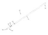
- FIG. 1is a perspective view of one embodiment of a guide pin, in accordance with an aspect of the present invention
- FIG. 2is a side view of the guide pin of FIG. 1 , in accordance with an aspect of the present invention
- FIG. 3is a side view of the first end of the guide pin of FIG. 1 , in accordance with an aspect of the present invention
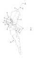
- FIG. 4is a top perspective view of one embodiment of a fastener, in accordance with an aspect of the present invention.
- FIG. 5is a bottom perspective view of the fastener of FIG. 3 , in accordance with an aspect of the present invention.
- FIG. 6is a side view of the fastener of FIG. 3 , in accordance with an aspect of the present invention.
- FIG. 7is a side view of the guide pin of FIG. 1 aligned with the fastener of FIG. 3 , in accordance with an aspect of the present invention
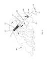
- FIG. 8is a medial view of the bones of a right foot with the guide pin of FIG. 1 inserted through two bones, in accordance with an aspect of the present invention
- FIG. 9is a lateral view of the right foot of FIG. 8 , in accordance with an aspect of the present invention.
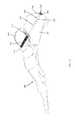
- FIG. 10is a posterior view of the right foot of FIG. 9 with the fastener of FIG. 4 inserted over the guide pin of FIG. 1 , in accordance with an aspect of the present invention
- FIG. 11is a posterior view of the right foot of FIG. 9 after removal of the guide pin, in accordance with an aspect of the present invention.
- FIG. 12is a medial view of the right foot of FIG. 11 , in accordance with an aspect of the present invention.
- FIG. 13depicts one embodiment of a surgical method for using the guide pin of FIG. 1 to insert a fastener, in accordance with an aspect of the present invention.
- a guide pin and a fastenerGenerally stated, disclosed herein is one embodiment of a guide pin and a fastener. Further, a surgical method for using the guide pin and fastener is discussed.
- proximal, distal, anterior, posterior, medial, lateral, superior and inferiorare defined by their standard usage for indicating a particular part of a bone or implant according to the relative disposition of the natural bone or directional terms of reference.
- proximalmeans the portion of a device or implant nearest the torso
- distalindicates the portion of the device or implant farthest from the torso.
- anterioris a direction towards the front side of the body
- posteriormeans a direction towards the back side of the body
- medialmeans towards the midline of the body
- lateralis a direction towards the sides or away from the midline of the body
- superiormeans a direction above and “inferior” means a direction below another object or structure.
- positions or directionsmay be used herein with reference to anatomical structures or surfaces.
- the bones of the foot, ankle and lower legmay be used to describe the surfaces, positions, directions or orientations of the devices, instrumentation and methods.
- the devices and methods, and the aspects, components, features and the like thereof, disclosed hereinare described with respect to one side of the body for brevity purposes.
- the device and methods, and the aspects, components, features and the like thereof, described and/or illustrated hereinmay be changed, varied, modified, reconfigured or otherwise altered for use or association with another side of the body for a same or similar purpose without departing from the spirit and scope of the invention.
- the devices and methods, and the aspects, components, features and the like thereof, described herein with respect to the right footmay be mirrored so that they likewise function with the left foot.
- the devices and methods, and the aspects, components, features and the like thereof, disclosed hereinare described with respect to the foot for brevity purposes, but it should be understood that the devices and methods may be used with other bones of the body having similar structures, for example the upper extremity, and more specifically, with the bones of the wrist, hand, and arm.
- the guide pin 100may be, for example, a cylindrical rod including a first end 102 and a second end 104 .
- the terms “guide pin,” “cylindrical rod,” “guide wire,” and “pin”may be used interchangeably herein as they essentially describe the same device.
- the first end 102may include a tip 106 and the tip 106 may be a sharp cutting point.
- the tip 106may penetrate a patient's soft tissue and/or bone.
- the guide pin 100may have a tip 106 at the first end 102 and the second end 104 .
- the guide pin 100 as shown in FIGS. 1-3may also include a smooth exterior surface 110 .
- the exterior surface 110may include threads (not shown) adjacent to the tip 106 .
- the guide pin 100may also include at least one circumferential indentation, notch, radial marking or recess 108 near the first end 102 .
- the terms “indentation,” “notch,” “radial marking” and “recess”may be used interchangeably herein as they essentially describe the same structure.
- the guide pin 100includes three recesses 108 , although any number of recesses is contemplated, for example, two or four recesses 108 .
- the recesses 108may be positioned at a distance (A), for example, about 5 mm to 20 mm, at a distance (B), for example, about 10 mm to 30 mm, and at a distance (C), for example, about 20 mm to 40 mm from the tip 106 of the guide pin 100 , as shown in FIG. 3 .
- the distances of the recesses 108 from the tip 106may be 16 mm for (A), 20 mm for (B) and 32 mm for (C).
- the distances (A), (B), and (C)may be measured from the tip 106 to the distal end of the recesses 108 , or the side of the recesses 108 closest to the second end 104 .
- the distances (A), (B), and (C)may correspond, for example, to the various thread lengths of a given sized bone screw, described in greater detail below, that may be used for insertion across the joint.
- the guide pin 100may also be used to measure the overall length of the screw that is needed for insertion into the bones or across a joint or bone fracture, as described in greater detail below. Thus, the overall length of the screw and the thread length of the screw may be selected using the guide pin 100 to ensure the two bone fragments are adequately compressed and joined together.
- the recesses 108may have a width of, for example, 1 mm to 3 mm and may be recessed a depth of, for example, about 0.20 mm to 0.50 mm from the exterior surface 110 .
- the recesses 108may also be circumferential around the guide pin 100 or only extend around a portion or partially around the guide pin 100 .
- the guide pin 100may also be used as a drill guide for inserting a drill into a patient's bone or across a patient's joint.
- the guide pin 100may be of the type described above with reference to FIGS. 1-3 , but may only include, for example, two recesses 108 positioned at distances (B) and (C).
- the distances (B) and (C)may correspond, for example, to two different size thread lengths of a given sized bone screw, as described in greater detail below.
- a bone screw with a shorter thread length than the thread lengths corresponding to distances (B) and (C)will be selected.
- the terms “bone screw,” “fastener,” “fixator,” “elongate member,” and “screw”may be used interchangeably herein as they essentially describe the same type of device.
- the bone screw 200may include a head portion 202 and a shaft portion 212 .
- the head portion 202may include a superior end 204 and an inferior end 206 .
- the superior end 204 of the head portion 202may have a tool engagement opening 208 and a cannulation or center hole 210 , as shown in FIG. 4 .
- the tool engagement opening 208may have a multi-lobed shape as shown in FIG. 4 , although other polygonal shapes are also contemplated.
- the shaft portion 212may include a smooth end 214 and a threaded end 216 for engaging a patient's bone, as seen in FIGS. 10-12 .
- the bone screw 200may be, for example, available in multiple sizes with threaded ends 216 of various lengths to correspond to the distances (A), (B), and (C) of the guide pin 100 .
- the threaded end 216 of fastener 200corresponds to the distance (C) of the guide pin 100 .
- the threaded end 216 of the shaft portion 212may also include at least one cutting tip 218 , as shown in FIG. 5 , to assist in insertion into the patient's bone. In the embodiment shown in FIG. 5 , the threaded end 216 includes four cutting tips 218 .
- FIGS. 8-13A surgical method using the guide pin 100 and fastener 200 is shown in FIGS. 8-13 .
- a guide pin 100is inserted into two adjacent bones in the foot 300 , for example, through the calcaneous bone 310 and into the talus bone 320 crossing the joint space between the bones.
- at least one imagefor example, using fluoroscopy, may be taken of the bones 310 , 320 and the guide pin 100 .
- the at least one imagemay be used to check the position of the guide pin 100 , the position of the radial markings 108 , and to ensure that the guide pin 100 crosses the space between the bones 310 , 320 .
- the imagewill be used to determine the location of the recesses 108 relative to the joint space, for example, the joint space between the bones 310 , 320 .
- the location of the recesses 108will then be analyzed to determine the necessary thread length 216 of the bone screw 200 for insertion, alignment, and adequate compression across the joint.
- the positioning of the recesses 108 of the guide pin 100allows the surgeon to determine the thread length of the screw. For example, as shown in FIG. 8 , the recesses 108 at distance A, B and C all extend through the joint space and into the bone 320 . Based on the positioning of the recess 108 at distance C, a screw having a thread length 216 of distance C, as shown in FIG.
- a depth gaugemay be aligned with the portion of the guide pin 100 extending out of the patient's incision or the screw entry point after the desired position of the guide pin 100 is obtained. The depth gauge may be used to measure the overall length of the screw that is needed. A screw may then be selected based on the measurements for the thread length 216 and overall screw length for insertion into a bone or across a joint as well as to ensure proper fusion orientation of the bones.
- a drillmay be inserted over the guide pin 100 and guided along the exterior surface 110 of the guide pin 100 from the second end 104 to the first end 102 to create an opening 112 for insertion of a bone screw 200 , as shown in FIG. 9 .
- a drill guide and/or tissue protectormay also be used during the insertion of the guide pin 100 and/or during the drilling of the opening 112 to assist in guiding the insertion of the guide pin 100 and the screw 200 as well as to protect the surrounding soft tissue.
- the drillmay be removed and the drill guide as well as the tissue protector may be removed.
- the selected bone screw 200may be inserted into the opening 112 by aligning the cannulation 210 of the bone screw 200 with the guide pin 100 and threading the screw 200 into the bones over the guide pin 100 , as shown in FIG. 10 .
- the guide pin 100may be removed. As shown in FIG. 12 , the bone screw 200 will pass through the joint between the bones 310 , 320 to hold the bones 310 , 320 in a desired position for bone fusion.
- the surgical methodmay include inserting a guide pin across the space between two bones 400 .
- an image of the bone joint space and guide pinmay be taken 410 .
- the methodmay also include analyzing the depth and position of the radial markings of the guide pin 420 to determine the necessary thread length of the fastener to ensure proper bone positioning post implantation.
- a fastenermay be selected 430 using the measured thread length and a drill may be selected and inserted over the guide pin to drill an opening in the bones 440 . After the opening is drilled the selected fastener may be inserted into the bones and across the joint through the opening 450 .
- a method or device that “comprises,” “has,” “includes,” or “contains” one or more steps or elementspossesses those one or more steps or elements, but is not limited to possessing only those one or more steps or elements.
- a step of a method or an element of a device that “comprises,” “has,” “includes,” or “contains” one or more featurespossesses those one or more features, but is not limited to possessing only those one or more features.
- a device or structure that is configured in a certain wayis configured in at least that way, but may also be configured in ways that are not listed.
Landscapes
- Health & Medical Sciences (AREA)
- Orthopedic Medicine & Surgery (AREA)
- Surgery (AREA)
- Life Sciences & Earth Sciences (AREA)
- Biomedical Technology (AREA)
- Public Health (AREA)
- Veterinary Medicine (AREA)
- Engineering & Computer Science (AREA)
- Nuclear Medicine, Radiotherapy & Molecular Imaging (AREA)
- Heart & Thoracic Surgery (AREA)
- Medical Informatics (AREA)
- Molecular Biology (AREA)
- Animal Behavior & Ethology (AREA)
- General Health & Medical Sciences (AREA)
- Neurology (AREA)
- Dentistry (AREA)
- Oral & Maxillofacial Surgery (AREA)
- Surgical Instruments (AREA)
Abstract
Description
Claims (9)
Priority Applications (3)
| Application Number | Priority Date | Filing Date | Title |
|---|---|---|---|
| US13/964,535US9848929B2 (en) | 2013-08-12 | 2013-08-12 | Devices and method of achieving bone fusion |
| PCT/US2014/050498WO2015023570A2 (en) | 2013-08-12 | 2014-08-11 | Devices and method of achieving bone fusion |
| US15/200,559US9962209B2 (en) | 2013-08-12 | 2016-07-01 | Devices and method of achieving bone fusion |
Applications Claiming Priority (1)
| Application Number | Priority Date | Filing Date | Title |
|---|---|---|---|
| US13/964,535US9848929B2 (en) | 2013-08-12 | 2013-08-12 | Devices and method of achieving bone fusion |
Related Child Applications (1)
| Application Number | Title | Priority Date | Filing Date |
|---|---|---|---|
| US15/200,559DivisionUS9962209B2 (en) | 2013-08-12 | 2016-07-01 | Devices and method of achieving bone fusion |
Publications (2)
| Publication Number | Publication Date |
|---|---|
| US20150045839A1 US20150045839A1 (en) | 2015-02-12 |
| US9848929B2true US9848929B2 (en) | 2017-12-26 |
Family
ID=52449260
Family Applications (2)
| Application Number | Title | Priority Date | Filing Date |
|---|---|---|---|
| US13/964,535Active2034-08-12US9848929B2 (en) | 2013-08-12 | 2013-08-12 | Devices and method of achieving bone fusion |
| US15/200,559ActiveUS9962209B2 (en) | 2013-08-12 | 2016-07-01 | Devices and method of achieving bone fusion |
Family Applications After (1)
| Application Number | Title | Priority Date | Filing Date |
|---|---|---|---|
| US15/200,559ActiveUS9962209B2 (en) | 2013-08-12 | 2016-07-01 | Devices and method of achieving bone fusion |
Country Status (2)
| Country | Link |
|---|---|
| US (2) | US9848929B2 (en) |
| WO (1) | WO2015023570A2 (en) |
Families Citing this family (40)
| Publication number | Priority date | Publication date | Assignee | Title |
|---|---|---|---|---|
| WO2015090954A1 (en)* | 2013-12-17 | 2015-06-25 | Stichting Katholieke Universiteit | Intramedullary device for mid-shaft clavicle fractures |
| US20160015426A1 (en) | 2014-07-15 | 2016-01-21 | Treace Medical Concepts, Inc. | Bone positioning and cutting system and method |
| US10245088B2 (en) | 2015-01-07 | 2019-04-02 | Treace Medical Concepts, Inc. | Bone plating system and method |
| US9687250B2 (en) | 2015-01-07 | 2017-06-27 | Treace Medical Concepts, Inc. | Bone cutting guide systems and methods |
| WO2016134154A1 (en) | 2015-02-18 | 2016-08-25 | Treace Medical Concepts, Inc. | Pivotable bone cutting guide useful for bone realignment and compression techniques |
| WO2016134160A1 (en) | 2015-02-18 | 2016-08-25 | Treace Medical Concepts, Inc. | Bone plating kit for foot and ankle applications |
| US10653467B2 (en) | 2015-05-06 | 2020-05-19 | Treace Medical Concepts, Inc. | Intra-osseous plate system and method |
| US9622805B2 (en) | 2015-08-14 | 2017-04-18 | Treace Medical Concepts, Inc. | Bone positioning and preparing guide systems and methods |
| US10849663B2 (en) | 2015-07-14 | 2020-12-01 | Treace Medical Concepts, Inc. | Bone cutting guide systems and methods |
| EP4483824A3 (en) | 2015-07-14 | 2025-03-05 | Treace Medical Concepts, Inc. | Bone positioning guide |
| EP4494582A3 (en) | 2015-08-14 | 2025-04-16 | Treace Medical Concepts, Inc. | Tarsal-metatarsal joint procedure utilizing fulcrum |
| WO2017031020A1 (en) | 2015-08-14 | 2017-02-23 | Treace Medical Concepts, Inc. | Tarsal-metatarsal joint procedure utilizing fulcrum |
| CA2998481C (en) | 2015-09-18 | 2024-05-14 | Treace Medical Concepts, Inc. | Joint spacer systems and methods |
| US10512470B1 (en) | 2016-08-26 | 2019-12-24 | Treace Medical Concepts, Inc. | Osteotomy procedure for correcting bone misalignment |
| US10524808B1 (en) | 2016-11-11 | 2020-01-07 | Treace Medical Concepts, Inc. | Devices and techniques for performing an osteotomy procedure on a first metatarsal to correct a bone misalignment |
| US10939939B1 (en) | 2017-02-26 | 2021-03-09 | Treace Medical Concepts, Inc. | Fulcrum for tarsal-metatarsal joint procedure |
| CN108209993B (en)* | 2018-01-23 | 2023-07-18 | 上海利格泰生物科技股份有限公司 | Ligament fixation screw reconstruction tool |
| US10405889B2 (en)* | 2018-06-14 | 2019-09-10 | New Standard Device, LLC | Cold forged cutting tip for orthopedic wires and pins |
| US11596443B2 (en) | 2018-07-11 | 2023-03-07 | Treace Medical Concepts, Inc. | Compressor-distractor for angularly realigning bone portions |
| US11583323B2 (en) | 2018-07-12 | 2023-02-21 | Treace Medical Concepts, Inc. | Multi-diameter bone pin for installing and aligning bone fixation plate while minimizing bone damage |
| US11607250B2 (en) | 2019-02-13 | 2023-03-21 | Treace Medical Concepts, Inc. | Tarsal-metatarsal joint procedure utilizing compressor-distractor and instrument providing sliding surface |
| CA3146564A1 (en) | 2019-08-07 | 2021-02-11 | Jason May | Bi-planar instrument for bone cutting and joint realignment procedure |
| US11889998B1 (en) | 2019-09-12 | 2024-02-06 | Treace Medical Concepts, Inc. | Surgical pin positioning lock |
| EP4027922A4 (en) | 2019-09-13 | 2023-10-04 | MIOS Marketing LLC, DBA RedPoint Medical 3D | Patient-specific surgical methods and instrumentation |
| US11890039B1 (en) | 2019-09-13 | 2024-02-06 | Treace Medical Concepts, Inc. | Multi-diameter K-wire for orthopedic applications |
| US11986251B2 (en) | 2019-09-13 | 2024-05-21 | Treace Medical Concepts, Inc. | Patient-specific osteotomy instrumentation |
| WO2021155269A1 (en) | 2020-01-31 | 2021-08-05 | Treace Medical Concepts, Inc. | Metatarsophalangeal joint preparation and metatarsal realignment for fusion |
| WO2021183647A1 (en)* | 2020-03-11 | 2021-09-16 | ExsoMed Corporation | Orthopedic implants and instruments for delivering the same |
| AU2021275140A1 (en) | 2020-05-19 | 2023-02-02 | Treace Medical Concepts, Inc. | Devices and techniques for treating metatarsus adductus |
| US12161371B2 (en) | 2021-01-18 | 2024-12-10 | Treace Medical Concepts, Inc. | Contoured bone plate with locking screw for bone compression, particularly across a tarsometatarsal joint |
| US12310603B2 (en) | 2021-02-18 | 2025-05-27 | Treace Medical Concepts, Inc. | System and technique for metatarsal realignment with reduced incision length |
| AU2022276540A1 (en) | 2021-05-20 | 2023-11-30 | Treace Medical Concepts, Inc. | Cut guide with integrated joint realignment features |
| AU2022343208A1 (en)* | 2021-09-09 | 2024-03-07 | ExsoMed Corporation | Orthopedic implants and instruments for delivering the same |
| USD1057155S1 (en) | 2022-02-23 | 2025-01-07 | Treace Medical Concepts, Inc. | Lesser metatarsal cut guide with parallel cut faces |
| USD1079011S1 (en) | 2022-02-23 | 2025-06-10 | Treace Medical Concepts, Inc. | Metatarsal cut guide with parallel cut faces |
| USD1011524S1 (en) | 2022-02-23 | 2024-01-16 | Treace Medical Concepts, Inc. | Compressor-distractor for the foot |
| USD1051382S1 (en) | 2022-02-23 | 2024-11-12 | Treace Medical Concepts, Inc. | Lesser metatarsal cut guide |
| USD1075012S1 (en) | 2022-02-23 | 2025-05-13 | Treace Medical Concepts, Inc. | Metatarsal lateral release instrument |
| USD1068077S1 (en) | 2023-02-08 | 2025-03-25 | Treace Medical Concepts, Inc. | Orthopedic rasp for preparing an intercuneiform joint |
| USD1068078S1 (en) | 2023-02-08 | 2025-03-25 | Treace Medical Concepts, Inc. | Handle for an orthopedic instrument |
Citations (4)
| Publication number | Priority date | Publication date | Assignee | Title |
|---|---|---|---|---|
| US5139500A (en)* | 1989-05-08 | 1992-08-18 | Schwartz Nathan H | Bone attachment system |
| US8128662B2 (en) | 2004-10-20 | 2012-03-06 | Vertiflex, Inc. | Minimally invasive tooling for delivery of interspinous spacer |
| US20120089191A1 (en)* | 2005-07-22 | 2012-04-12 | Exactech, Inc. | Methods for stabilizing bone structures |
| US20130090658A1 (en)* | 2011-09-08 | 2013-04-11 | Linvatec Corporation | Guide Pin Gauge |
Family Cites Families (4)
| Publication number | Priority date | Publication date | Assignee | Title |
|---|---|---|---|---|
| US4421112A (en)* | 1982-05-20 | 1983-12-20 | Minnesota Mining And Manufacturing Company | Tibial osteotomy guide assembly and method |
| US5098435A (en)* | 1990-11-21 | 1992-03-24 | Alphatec Manufacturing Inc. | Cannula |
| US20090149862A1 (en)* | 2007-12-10 | 2009-06-11 | Sym Partners, Llc | Guide pin for pedicle screw placement and method for use of such guide pin in spinal fusion surgeries |
| US11051864B2 (en)* | 2012-08-30 | 2021-07-06 | DePuy Synthes Products, Inc. | Intramedullary fixation assembly |
- 2013
- 2013-08-12USUS13/964,535patent/US9848929B2/enactiveActive
- 2014
- 2014-08-11WOPCT/US2014/050498patent/WO2015023570A2/enactiveApplication Filing
- 2016
- 2016-07-01USUS15/200,559patent/US9962209B2/enactiveActive
Patent Citations (4)
| Publication number | Priority date | Publication date | Assignee | Title |
|---|---|---|---|---|
| US5139500A (en)* | 1989-05-08 | 1992-08-18 | Schwartz Nathan H | Bone attachment system |
| US8128662B2 (en) | 2004-10-20 | 2012-03-06 | Vertiflex, Inc. | Minimally invasive tooling for delivery of interspinous spacer |
| US20120089191A1 (en)* | 2005-07-22 | 2012-04-12 | Exactech, Inc. | Methods for stabilizing bone structures |
| US20130090658A1 (en)* | 2011-09-08 | 2013-04-11 | Linvatec Corporation | Guide Pin Gauge |
Non-Patent Citations (1)
| Title |
|---|
| Feb. 3, 2015: International Preliminary Report on Patentability for International Application No. PCT/US2014/050498. |
Also Published As
| Publication number | Publication date |
|---|---|
| US9962209B2 (en) | 2018-05-08 |
| WO2015023570A2 (en) | 2015-02-19 |
| US20150045839A1 (en) | 2015-02-12 |
| WO2015023570A3 (en) | 2015-04-09 |
| US20160310189A1 (en) | 2016-10-27 |
Similar Documents
| Publication | Publication Date | Title |
|---|---|---|
| US9962209B2 (en) | Devices and method of achieving bone fusion | |
| US11779382B2 (en) | Alignment guide apparatus, methods and systems | |
| US20250152188A1 (en) | Intramedullary nail fixation guides, devices, and methods of use | |
| US12396768B2 (en) | Intramedullary nail alignment guides, fixation guides, devices, systems, and methods of use | |
| US20220079608A1 (en) | Targeting instruments, systems and methods of use | |
| AU2015308660B2 (en) | Proximal bunion resection guides and plates and methods of use | |
| US10349990B2 (en) | Method and device for attaching a bone plate | |
| US6702823B2 (en) | Device for identifying the position of intramedullary nail securement screw holes | |
| US20160310191A1 (en) | Articulating Syndesmosis Targeting Guide Device and Method | |
| US20130325076A1 (en) | Lower extremity fusion devices and methods | |
| WO2015094409A1 (en) | Alignment guide apparatus, methods and systems | |
| WO2019112605A1 (en) | Bone fixation assembly, implants and methods of use | |
| KR20210013549A (en) | System for anchor placement | |
| US20170360577A1 (en) | Implants, devices, systems, kits and methods of implanting | |
| US20250160855A1 (en) | Intramedullary nail fixation guides, devices, and methods of use |
Legal Events
| Date | Code | Title | Description |
|---|---|---|---|
| AS | Assignment | Owner name:PARAGON 28, INC., COLORADO Free format text:ASSIGNMENT OF ASSIGNORS INTEREST;ASSIGNORS:DACOSTA, ALBERT;SAN GIOVANNI, THOMAS, MD;HOUGHTON, MICHAEL, MD;SIGNING DATES FROM 20130807 TO 20130809;REEL/FRAME:031003/0867 | |
| AS | Assignment | Owner name:ZB, N.A. D/B/A VECTRA BANK COLORADO, COLORADO Free format text:SECURITY INTEREST;ASSIGNOR:PARAGON 28, INC.;REEL/FRAME:042589/0001 Effective date:20170518 | |
| STCF | Information on status: patent grant | Free format text:PATENTED CASE | |
| AS | Assignment | Owner name:ZIONS BANCORPORATION, N.A. DBA VECTRA BANK COLORADO, COLORADO Free format text:MERGER;ASSIGNOR:ZB, N.A. D/B/A VECTRA BANK COLORADO;REEL/FRAME:047734/0710 Effective date:20180930 Owner name:ZIONS BANCORPORATION, N.A. DBA VECTRA BANK COLORAD Free format text:MERGER;ASSIGNOR:ZB, N.A. D/B/A VECTRA BANK COLORADO;REEL/FRAME:047734/0710 Effective date:20180930 | |
| AS | Assignment | Owner name:ZIONS BANCORPORATION, N.A. DBA VECTRA BANK COLORADO, COLORADO Free format text:CORRECTIVE ASSIGNMENT TO CORRECT THE NATURE OF CONVEYANCE TO SECURITY AGREEMENT PREVIOUSLY RECORDED ON REEL 047734 FRAME 0710. ASSIGNOR(S) HEREBY CONFIRMS THE SECURITY AGREEMENT;ASSIGNOR:ZB, N.A. D/B/A VECTRA BANK;REEL/FRAME:053796/0839 Effective date:20180930 | |
| AS | Assignment | Owner name:PARAGON 28, INC., COLORADO Free format text:RELEASE BY SECURED PARTY;ASSIGNOR:ZIONS BANCORPORATION, N.A. DBA VECTRA BANK COLORADO, AS SUCCESSOR-BY-MERGER TO ZB, N.A. DBA VECTRA BANK COLORADO;REEL/FRAME:056320/0224 Effective date:20210506 Owner name:MIDCAP FINANCIAL TRUST, AS ADMINISTRATIVE AGENT, MARYLAND Free format text:SECURITY INTEREST (REVOLVING);ASSIGNOR:PARAGON 28, INC.;REEL/FRAME:056320/0316 Effective date:20210506 Owner name:MIDCAP FINANCIAL TRUST, AS ADMINISTRATIVE AGENT, MARYLAND Free format text:SECURITY INTEREST (TERM);ASSIGNOR:PARAGON 28, INC.;REEL/FRAME:056320/0335 Effective date:20210506 | |
| MAFP | Maintenance fee payment | Free format text:PAYMENT OF MAINTENANCE FEE, 4TH YR, SMALL ENTITY (ORIGINAL EVENT CODE: M2551); ENTITY STATUS OF PATENT OWNER: SMALL ENTITY Year of fee payment:4 | |
| AS | Assignment | Owner name:ARES CAPITAL CORPORATION, NEW YORK Free format text:SECURITY INTEREST;ASSIGNORS:PARAGON 28, INC.;PARAGON ADVANCED TECHNOLOGIES, INC.;REEL/FRAME:065448/0214 Effective date:20231102 | |
| AS | Assignment | Owner name:PARAGON 28, INC., COLORADO Free format text:RELEASE OF INTELLECTUAL PROPERTY SECURITY INTEREST AT REEL/FRAME NO. 56320/0316;ASSIGNOR:MIDCAP FINANCIAL TRUST, AS AGENT;REEL/FRAME:065548/0338 Effective date:20231102 Owner name:PARAGON 28, INC., COLORADO Free format text:RELEASE OF INTELLECTUAL PROPERTY SECURITY INTEREST AT REEL/FRAME NO. 56320/0335;ASSIGNOR:MIDCAP FINANCIAL TRUST, AS AGENT;REEL/FRAME:065548/0284 Effective date:20231102 | |
| AS | Assignment | Owner name:PARAGON ADVANCED TECHNOLOGIES, INC., COLORADO Free format text:RELEASE BY SECURED PARTY;ASSIGNOR:ARES CAPITAL CORPORATION;REEL/FRAME:070908/0038 Effective date:20250421 Owner name:PARAGON 28, INC., COLORADO Free format text:RELEASE BY SECURED PARTY;ASSIGNOR:ARES CAPITAL CORPORATION;REEL/FRAME:070908/0038 Effective date:20250421 | |
| MAFP | Maintenance fee payment | Free format text:PAYMENT OF MAINTENANCE FEE, 8TH YR, SMALL ENTITY (ORIGINAL EVENT CODE: M2552); ENTITY STATUS OF PATENT OWNER: SMALL ENTITY Year of fee payment:8 |