US9848922B2 - Systems and methods for performing spine surgery - Google Patents
Systems and methods for performing spine surgeryDownload PDFInfo
- Publication number
- US9848922B2 US9848922B2US14/511,038US201414511038AUS9848922B2US 9848922 B2US9848922 B2US 9848922B2US 201414511038 AUS201414511038 AUS 201414511038AUS 9848922 B2US9848922 B2US 9848922B2
- Authority
- US
- United States
- Prior art keywords
- rod
- user
- spinal
- screw
- bend
- Prior art date
- Legal status (The legal status is an assumption and is not a legal conclusion. Google has not performed a legal analysis and makes no representation as to the accuracy of the status listed.)
- Active
Links
Images


Classifications
- A—HUMAN NECESSITIES
- A61—MEDICAL OR VETERINARY SCIENCE; HYGIENE
- A61B—DIAGNOSIS; SURGERY; IDENTIFICATION
- A61B17/00—Surgical instruments, devices or methods
- A61B17/56—Surgical instruments or methods for treatment of bones or joints; Devices specially adapted therefor
- A61B17/58—Surgical instruments or methods for treatment of bones or joints; Devices specially adapted therefor for osteosynthesis, e.g. bone plates, screws or setting implements
- A61B17/68—Internal fixation devices, including fasteners and spinal fixators, even if a part thereof projects from the skin
- A61B17/70—Spinal positioners or stabilisers, e.g. stabilisers comprising fluid filler in an implant
- A61B17/7074—Tools specially adapted for spinal fixation operations other than for bone removal or filler handling
- A61B17/7083—Tools for guidance or insertion of tethers, rod-to-anchor connectors, rod-to-rod connectors, or longitudinal elements
- A61B17/7086—Rod reducers, i.e. devices providing a mechanical advantage to allow a user to force a rod into or onto an anchor head other than by means of a rod-to-bone anchor locking element; rod removers
- A—HUMAN NECESSITIES
- A61—MEDICAL OR VETERINARY SCIENCE; HYGIENE
- A61B—DIAGNOSIS; SURGERY; IDENTIFICATION
- A61B17/00—Surgical instruments, devices or methods
- A61B17/56—Surgical instruments or methods for treatment of bones or joints; Devices specially adapted therefor
- A61B17/58—Surgical instruments or methods for treatment of bones or joints; Devices specially adapted therefor for osteosynthesis, e.g. bone plates, screws or setting implements
- A61B17/68—Internal fixation devices, including fasteners and spinal fixators, even if a part thereof projects from the skin
- A61B17/70—Spinal positioners or stabilisers, e.g. stabilisers comprising fluid filler in an implant
- A61B17/7074—Tools specially adapted for spinal fixation operations other than for bone removal or filler handling
- A61B17/7083—Tools for guidance or insertion of tethers, rod-to-anchor connectors, rod-to-rod connectors, or longitudinal elements
- A—HUMAN NECESSITIES
- A61—MEDICAL OR VETERINARY SCIENCE; HYGIENE
- A61B—DIAGNOSIS; SURGERY; IDENTIFICATION
- A61B17/00—Surgical instruments, devices or methods
- A61B17/56—Surgical instruments or methods for treatment of bones or joints; Devices specially adapted therefor
- A61B17/58—Surgical instruments or methods for treatment of bones or joints; Devices specially adapted therefor for osteosynthesis, e.g. bone plates, screws or setting implements
- A61B17/88—Osteosynthesis instruments; Methods or means for implanting or extracting internal or external fixation devices
- A61B17/8863—Apparatus for shaping or cutting osteosynthesis equipment by medical personnel
- A—HUMAN NECESSITIES
- A61—MEDICAL OR VETERINARY SCIENCE; HYGIENE
- A61B—DIAGNOSIS; SURGERY; IDENTIFICATION
- A61B34/00—Computer-aided surgery; Manipulators or robots specially adapted for use in surgery
- A61B34/25—User interfaces for surgical systems
- A—HUMAN NECESSITIES
- A61—MEDICAL OR VETERINARY SCIENCE; HYGIENE
- A61B—DIAGNOSIS; SURGERY; IDENTIFICATION
- A61B17/00—Surgical instruments, devices or methods
- A61B17/56—Surgical instruments or methods for treatment of bones or joints; Devices specially adapted therefor
- A61B17/58—Surgical instruments or methods for treatment of bones or joints; Devices specially adapted therefor for osteosynthesis, e.g. bone plates, screws or setting implements
- A61B17/68—Internal fixation devices, including fasteners and spinal fixators, even if a part thereof projects from the skin
- A61B17/80—Cortical plates, i.e. bone plates; Instruments for holding or positioning cortical plates, or for compressing bones attached to cortical plates
- A61B17/808—Instruments for holding or positioning bone plates, or for adjusting screw-to-plate locking mechanisms
- A—HUMAN NECESSITIES
- A61—MEDICAL OR VETERINARY SCIENCE; HYGIENE
- A61B—DIAGNOSIS; SURGERY; IDENTIFICATION
- A61B34/00—Computer-aided surgery; Manipulators or robots specially adapted for use in surgery
- A61B34/20—Surgical navigation systems; Devices for tracking or guiding surgical instruments, e.g. for frameless stereotaxis
- A61B2034/2046—Tracking techniques
- A61B2034/2055—Optical tracking systems
- A—HUMAN NECESSITIES
- A61—MEDICAL OR VETERINARY SCIENCE; HYGIENE
- A61B—DIAGNOSIS; SURGERY; IDENTIFICATION
- A61B34/00—Computer-aided surgery; Manipulators or robots specially adapted for use in surgery
- A61B34/25—User interfaces for surgical systems
- A61B2034/254—User interfaces for surgical systems being adapted depending on the stage of the surgical procedure
- A—HUMAN NECESSITIES
- A61—MEDICAL OR VETERINARY SCIENCE; HYGIENE
- A61B—DIAGNOSIS; SURGERY; IDENTIFICATION
- A61B90/00—Instruments, implements or accessories specially adapted for surgery or diagnosis and not covered by any of the groups A61B1/00 - A61B50/00, e.g. for luxation treatment or for protecting wound edges
- A61B90/39—Markers, e.g. radio-opaque or breast lesions markers
- A61B2090/3983—Reference marker arrangements for use with image guided surgery
Definitions
- the present applicationpertains to spine surgery. More particularly, the present application pertains to systems and methods related to the planning, design, formation, and implantation of spinal implants.
- the spinal columnis a highly complex system of bones and connective tissues that provide support for the body and protect the delicate spinal cord and nerves.
- the spinal columnincludes a series of vertebral bodies stacked atop one another, each vertebral body including an inner or central portion of relatively weak cancellous bone and an outer portion of relatively strong cortical bone. Situated between each vertebral body is an intervertebral disc that cushions and dampens compressive forces exerted upon the spinal column.
- a vertebral canal containing the spinal cordis located behind the vertebral bodies.
- the spinehas a natural curvature (i.e., lordosis in the lumbar and cervical regions and kyphosis in the thoracic region) such that the endplates of the upper and lower vertebrae are inclined towards one another.
- spinal column disordersincluding scoliosis (abnormal lateral curvature of the spine), excess kyphosis (abnormal forward curvature of the spine), excess lordosis (abnormal backward curvature of the spine), spondylolisthesis (forward displacement of one vertebra over another), and other disorders caused by abnormalities, disease, or trauma (such as ruptured or slipped discs, degenerative disc disease, fractured vertebrae, and the like). Patients that suffer from such conditions often experience extreme and debilitating pain, as well as diminished nerve function. Posterior fixation for spinal fusions, decompression, deformity, and other reconstructions are performed to treat these patients. The aim of posterior fixation in lumbar, thoracic, and cervical procedures is to stabilize the spinal segments, correct multi-axis alignment, and aid in optimizing the long-term health of the spinal cord and nerves.
- Screws, hooks, and rodsare devices used to stabilize the spine during a spinal fixation procedure. Such procedures often require the instrumentation of many bony elements.
- the devices, for example rodscan be extremely challenging to design and implant into the patient.
- Spinal rodsare usually formed of stainless steel, titanium, cobalt chrome, or other similarly hard metal, and as such are difficult to bend without some sort of leverage-based bender.
- a spinal rodneeds to be oriented in six degrees of freedom to compensate for the anatomical structure of a patient's spine as well as the attachment points (screws, hooks) for securing the rod to the vertebrae. Additionally, the physiological problem being treated as well as the physician's preferences will determine the exact configuration necessary.
- the size, length, and particular bends of the spinal roddepends on the size, number, and position of each vertebrae to be constrained, the spatial relationship amongst vertebrae, as well as the screws and hooks used to hold the rods attached to the vertebrae.
- the bending of a spinal rodcan be accomplished by a number of methods.
- the most widely used methodis a three-point bender called a French Bender.
- the French benderis a pliers-like device that is manually operated to place one or more bends in a rod.
- the French benderrequires both handles to operate and provides leverage based on the length of the handle.
- the use of the French benderrequires a high degree of physician skill because the determination of the location, angle, and rotation of bends is often subjective and can be difficult to correlate to a patient's anatomy.
- Other methods of bending a rod to fit a screw and/or hook constructinclude the use of an in-situ rod bender and a keyhole bender.
- rod bending and reduction activitiescan be a time consuming and potentially frustrating step in the finalization of a complex and/or long spinal construct.
- Increased time in the operating room to achieve optimum bendingcan be costly to the patient and increase the chance of the morbidity.
- the rodcan preload the construct and increase the chance of failure of the fixation system.
- the bending and re-bending involvedcan also promote metal fatigue and the creation of stress risers in the rod.
- U.S. Pat. No. 7,957,831issued Jun. 7, 2011 to Isaacs, describes a rod bending system which includes a spatial measurement sub-system with a digitizer to obtain the three dimensional location of surgical implants (screws, hooks), software to convert the implant locations to a series of bend instructions, and a mechanical rod bender used to execute the bend instructions such that the rod will be bent precisely to custom fit within each of the screws.
- the present inventionincludes a system and methods for rod bending that enable the user (e.g., surgeon) to customize screw-based rod bend instructions to suit the desired correction of a patient's spinal condition.
- the present inventionincludes a spatial tracking system for obtaining the three-dimensional position information of surgical implants, a processing system with software to convert the implant locations to a series of bend instructions based on a desired correction, and a mechanical rod bender for bending a surgical linking device to achieve the desired spinal correction.
- the spatial tracking systemincludes an infrared (IR) position sensor and at least one IR-reflective tracking array attached to a digitizer pointer used to digitize the surgical implant location.
- the spatial tracking systemis communicatively linked to the processing system such that the processing system may utilize the spatial position information to generate bend instructions.
- the processing systemis programmed to generate bend instructions based on one or more surgeon-prescribed clinical objectives.
- the processing systemmay be programmed to create a custom bend, adjust one or more points to which the rod will be bent to, suggest a pre-bent rod option, provide spinal correction in the sagittal plane, provide spinal correction in the coronal plane, and provide correction to achieve global spinal balance, and as well as perform a plurality of predetermined functions.
- the processing systemis further configured to preview and display the results of these clinical objectives and/or predetermined functions to the user in a meaningful way.
- the spatial tracking systemis configured to track the three-dimensional position of a spinal rod relative to the implanted surgical implants during rod insertion.
- the spatial tracking systemmay include at least one IR-reflective tracking array attached to a rod inserter instrument and another attached to a screw guide rod pusher to continuously digitize the rod location in real time during insertion of the rod.
- the processing systemis programmed to generate and display the real time three-dimensional location of the rod tip relative to the tip of the rod pusher and the implanted surgical implants.
- one or more surgical proceduresmay be performed using various embodiments of the system.
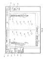
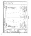
- FIG. 1is a surgical procedure setup depicting the components of a surgical bending system, according to one embodiment
- FIG. 2is a perspective view of one embodiment of a digitizer array in the closed position comprising part of the system of FIG. 1 ;
- FIG. 3is an exploded perspective view of the digitizer array of FIG. 2 ;
- FIG. 4is a perspective view of the digitizer array of FIG. 2 in the open position
- FIG. 5is a front view of one embodiment of a digitizer pointer assembly comprising part of the system of FIG. 1 ;
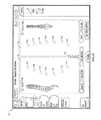
- FIG. 6is a perspective view of various surgical pointers compatible with the digitizer array of FIG. 2 ;
- FIG. 7is a partial perspective view of the offset pointer of FIG. 6 in a collapsed position
- FIG. 8is a partial exploded view of the offset pointer of FIG. 6 ;
- FIG. 9is a partial perspective view of the offset pointer of FIG. 6 in an extended position
- FIG. 10is a flowchart depicting the steps of the spatial tracking algorithm according to one embodiment
- FIG. 11is a flowchart depicting the rod bending workflow according to one embodiment
- FIG. 12is a flowchart depicting the steps in generating a rod solution according to a first embodiment
- FIG. 13is a flowchart depicting the steps in generating rod solution according to a second embodiment
- FIG. 14is a flowchart depicting the steps in generating a rod solution according to a third embodiment
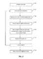
- FIG. 15is a flowchart depicting the steps of the rod bending process according to a first embodiment
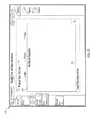
- FIG. 16is a screen shot depicting an example setup screen of the system of FIG. 1 ;
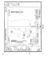
- FIG. 17is a screen shot depicting an example IR positioning sensor setup screen of the system of FIG. 1 ;
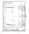
- FIG. 18is a screen shot depicting an example screw location digitization screen during a first step in the Acquire Screws step of FIG. 15 ;
- FIG. 19is a screen shot depicting an example screw location digitization screen during a second step in the Acquire Screws step of FIG. 15 ;
- FIG. 20is a screen shot depicting an example screw digitization screen during a third step in the Acquire Screws step of FIG. 15 ;
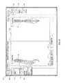
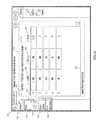
- FIG. 21is a screen shot depicting an example bend instructions screen in the Bend Instructions step of FIG. 15 ;
- FIG. 22is a flowchart depicting the steps of the rod bending process according to a second embodiment
- FIG. 23is a screen shot depicting an example Advanced Options menu screen of the system of FIG. 1 ;
- FIG. 24is a screen shot illustrating a first example screen of an Adjust Points feature according to one embodiment
- FIG. 25is a screen shot illustrating a second example screen of the Adjust Points feature of FIG. 24 ;
- FIG. 26is a screen shot illustrating a third example screen of the Adjust Points feature of FIG. 24 ;
- FIG. 27is a screen shot illustrating a first example screen of a Pre-Bent Preview feature according to one embodiment
- FIG. 28is a screen shot illustrating a second example screen of the Pre-Bent Preview feature of FIG. 27 ;
- FIG. 29is a screen shot illustrating a third example screen of the Pre-Bent Preview feature of FIG. 27 ;
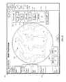
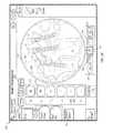
- FIG. 30is a screen shot illustrating a first example screen of a Sagittal Correction feature according to one embodiment
- FIG. 31is a screen shot illustrating a second example screen of the Sagittal Correction feature according to the first embodiment
- FIG. 32is a screen shot illustrating a first example screen of the Sagittal Correction feature according to a second embodiment
- FIG. 33is a screen shot illustrating an additional example screen of the Sagittal Correction feature according to the first and/or second embodiment
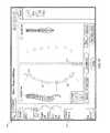
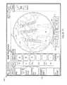
- FIG. 34is a screen shot illustrating a first example screen of the Coronal Correction feature according to a first embodiment
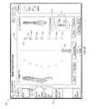
- FIG. 35is a screen shot illustrating a second example screen of the Coronal Correction feature according to a first embodiment
- FIG. 36is a screen shot illustrating a third example screen of the Coronal Correction feature according to the first embodiment
- FIG. 37is a screen shot illustrating a fourth example screen of the Coronal Correction feature according to the first embodiment
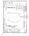
- FIG. 38is a screen shot illustrating a first example screen of the Coronal Correction feature according to a second embodiment
- FIG. 39is a screen shot illustrating a second example screen of the Coronal Correction feature according to the second embodiment.
- FIG. 40is a screen shot illustrating a third example screen of the Coronal Correction feature according to the second embodiment.
- FIG. 41is a flowchart illustrating the steps of the Global Spinal Balance feature according to one embodiment
- FIG. 42is a screen shot illustrating a first example screen of the Global Spinal Balance feature in pre-operative mode
- FIG. 43is a screen shot illustrating a first example screen of the Global Spinal Balance feature in target mode
- FIG. 44is a screen shot illustrating a second example screen of the Global Spinal Balance feature in target mode
- FIG. 45is a screen shot illustrating a first example screen of the Global Spinal Balance feature in intraoperative mode
- FIG. 46is a screen shot illustrating a second example screen of the Global Spinal Balance feature in intraoperative mode
- FIG. 47is a screen shot illustrating a third example screen of the Global Spinal Balance feature in intraoperative mode
- FIG. 48is a screen shot illustrating a fourth example screen of the Global Spinal Balance feature in intraoperative mode
- FIG. 49is a screen shot illustrating a fifth example screen of the Global Spinal Balance feature in intraoperative mode
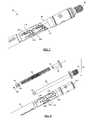
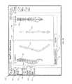
- FIG. 50is a perspective view of one embodiment of a mechanical rod bender comprising part of the surgical bending system of FIG. 1 ;
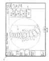
- FIG. 51is a perspective view of a lumbar spine illustrating example spinal fixation anchors with attached extension guides and an example rod pusher instrument in use during implantation of a two level fixation construct, according to one example;
- FIG. 52is a perspective view of the example rod pusher of FIG. 51 ;
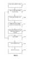
- FIG. 53is a plan view of an example rod inserter configured for use in the implantation procedure of FIG. 51 ;
- FIG. 54is a screen shot illustrating a first example screen of the Rod Tracking feature according to one embodiment.
- FIG. 55is a screen shot illustrating a second example screen of the Rod Tracking feature according to one embodiment.
- a surgical bending system 10including a spatial tracking system 12 to obtain the location of one or more surgical implants 14 , a control unit 16 containing software to convert the implant locations to a series of bend instructions, and a bending device 18 to execute the bend instructions.
- the spatial tracking system 12includes an IR sensor 20 , a digitizer pointer 23 , as well as other components including Host USB converter 21 .
- the spatial tracking system 12is in communication with control unit 16 .
- the control unit 16has spatial relation software and is communicatively linked to the display 32 so that information relevant to the surgical procedure may be conveyed to the user in a meaningful manner.
- the relevant informationincludes, but is not limited to, spatial positioning data (e.g., translational data in the x, y, and z axes and orientation/rotational data R x , R y , and R z ) acquired by the IR sensor 20 .
- the system 10comprises a neuromonitoring system communicatively linked to the spatial tracking system 12 via the control unit 16 .
- the neuromonitoring systemmay be the neuromonitoring system shown and described in U.S. Pat. No. 8,255,045, entitled “Neurophysiologic Monitoring System” and filed on Apr. 3, 2008, the entire contents of which are hereby incorporated by reference as if set forth fully herein.
- FIGS. 2-9depict the various components of one or more digitizer pointers 23 for use with the present invention.
- FIGS. 2-4detail an example IR-reflective tracking array 22 component of the digitizer pointer 23 .
- Array 22includes a housing 34 , bilateral shutters 36 , and a plurality of IR-reflective spheres 38 arranged in a calculated manner at various locations on the array 22 such that their position information is selectively detectable by the IR sensor 20 .
- Housing 34comprises a top housing 40 , bottom housing 42 , and a distal threaded aperture 56 configured to threadably receive the threaded end 78 of a stylus (e.g., stylus 24 , 26 , 28 , and/or 30 ).
- a styluse.g., stylus 24 , 26 , 28 , and/or 30 .
- Top housing portion 40is further comprised of upper portion 44 , underside 46 , and sides 48 .
- a plurality of sphere apertures 52extend between upper portion 44 and underside 46 and are sized and dimensioned to receive reflective spheres 38 within recessed pockets 54 .
- Each side 48includes cutout 50 sized and dimensioned to receive tongue 70 .
- Bottom housing 42is comprised of a first face 58 and a second face 60 .
- the first face 58includes nesting platforms 62 and bullet posts 64 .
- Each shutter 36includes handle portion 66 , cover portion 68 , tongue 70 , interdigitating gear teeth 72 , and channel 74 for receiving bullet posts 64 .
- a spring 76extends between the two shutters 36 and is held in place via spring posts 71 .
- each IR-reflective sphere 38is nested on a platform 62 .
- Top housing 40is placed over bottom housing 42 in a snap fit configuration such that each IR-reflective sphere 38 fits within a recessed pocket 54 within its respective sphere aperture 52 .
- bilateral shutters 36are positioned over the housing 34 with tongues 70 sliding into cutouts 50 such that each shutter cover 68 obscures exactly one half of the IR-reflective sphere 38 (for example, the middle IR-reflective sphere 38 ) as depicted in FIG. 2 .
- the IR-reflective tracking array 22mates with one or more surgical objects (for example styluses 24 , 26 , 28 , 30 ).
- Each stylus 24 , 26 , 28 , 30includes a threaded proximal end 78 for mating with the threaded distal aperture 56 of the IR-reflective tracking array 22 , elongate shaft 80 , and shaped distal tip 82 .
- Shaped distal tip 82may be any shape that is complimentary to, and fits securely within, the shape of a particular screw head. For example, FIG.
- FIG. 6shows styluses 24 , 26 , 28 , and 30 each with a different shaped distal tip designed to mate with different open screw systems, minimally-invasive screw systems, and closed tulip, iliac, and offset connector systems.
- the distal tip 82is preferably inserted into each screw while orienting the digitizer pointer coaxial to that screw (or other fixation device).
- the length of the elongate shaft 80is fixed relative to the array 22 such that all digitized points are a consistent length from the geometry of the IR-reflective markers 38 and position information may be obtained from this relationship.
- the length of the elongate shaft 80is adjustable relative to the array 22 such as that shown with stylus 30 , effectively elongating the distance from the digitized point and the IR-reflective markers. This longer distance translates to digitization of a point above the actual screw head based on the distance the user adjusted the elongate shaft 80 .
- the resulting bend instructionswould shape a rod that traverses that point above the screw allowing the user to reduce the screw to the rod.
- offset pointer 30includes an elongate tubular member 84 and an inner piston 86 .
- Elongate tubular member 84is comprised of a milled helical slot 104 and a plurality of offset depth slots 106 located around the helix that correspond to a plurality of offset distances as will be described below.
- Inner piston 86includes shaft 88 , T-shaped cap 92 , springs 94 , and bushing 96 .
- the T-shaped cap 92is positioned over the proximal end of the shaft 88 and is preferably welded to the proximal end 105 of the elongate tubular member 84 .
- Springs 94are slideably positioned along the length of the shaft 88 between the distal end 93 of the T-shaped cap 92 and bushing 96 .
- Bushing 96is positioned over the distal end of the shaft 88 .
- Pin 100is travels through, and protrudes laterally from, slots 90 , 98 on the inner shaft 88 and bushing 96 , thereby securing the bushing 96 to the inner shaft 88 .
- the pin 100is sized and dimensioned such that it travels through the helical slot 104 and be positioned within each of the offset depth slots 106 .
- the offset pointer 30gives the user the ability to execute planned screw movement by a specific amount.
- the userinserts the offset pointer 30 into the screw head. Keeping the distal tip 82 engaged to the screw head, the user then selects an offset amount to be added to the screw and angles the offset pointer 30 in the direction he or she wishes to apply the offset to.
- the shaft 88is pulled away from the array 22 and twisted until the pin 100 falls into the desired offset slot 106 . As the shaft 88 is pulled, it telescopes in and out of the elongate tubular member 84 such that the distance between the shaped distal end 82 and the array 22 is increased. For purposes of illustration, FIG.
- Offset optionsmay be provided, by way of example only from 0 mm to 16 mm offsets in 2 mm increments. The system 10 will then acquire position information at that
- the digitizer pointer 23may be used to acquire positional information about some or all screw locations.
- the shaped distal tip 82is coaxially aligned into the screw head and the array 22 is triggered to register the screw point.
- Screw locationsmay be digitized in a superior-inferior or inferior-superior direction.
- the first screw location digitizedcorrelates to the rod insertion direction component of the bend instructions (described below).
- Squeezing handles 66activates the spring mechanism and permits the shutters 36 to open equally via the interdigitating gear teeth 72 ( FIG. 4 ).
- Opening the shutter covers 68exposes the middle IR-reflective sphere 38 and allows the IRtracking array 22 to be “seen” by the IR sensor 20 and the position of the digitizer pointer 23 to be digitized. In this way, the IR sensor 20 only recognizes the digitizer pointer 23 once the middle sphere 38 is exposed which allows for point-by-point tracking and obviates the sensing and digitization of one or more unnecessary data points which may occur with prior art systems that continually track surgical objects. Further, use of the gear mechanism allows the passive IR-reflective sphere 38 to be “seen” symmetrically by the IR sensor 20 , thereby enabling a more accurate calculation of position information by the system 10 .
- control unit 16emits an audible sound to notify the user that the middle sphere 38 is recognized by the IR sensor 20 and the screw point is acquired. Once a point has been registered, the shutter handles 66 may be released, thereby closing the bilateral shutters 36 . This process is then repeated for all screw locations to be digitized.
- the surgical bending algorithmsmay be divided into two smaller sub-systems: (1) the spatial location algorithms that acquire, collect, and digitize points in space and (2) the bending algorithms that analyze the points and calculate the bend instructions and rod length needed to bend a rod with the mechanical bending device 18 .
- the spatial tracking system 12measures the six degrees of freedom (6 DOF) information for the tracked IR-reflective spheres 38 . These data provide the full pose (position and orientation) of each screw of interest which may then be made available to the algorithm library to calculate the bend instructions.
- FIG. 10is a flow chart indicating the steps of the spatial location data acquisition process according to one embodiment.
- the system 10initializes the sensor objects from configuration to connect to, control, and read data from the IR sensor 20 (step 140 ).
- the system 10inspects all devices connected to it and finds the device with a device ID that corresponds to the IR sensor 20 (step 141 ).
- step 142if an IR sensor 20 is found at step 141 , the system 10 continues to establish a connection with the IR sensor 20 (step 143 ). However, if not the system 10 continues to search. After the system 10 connects to the IR sensor 20 , it then loads a tool file that defines the array 22 (step 144 ). After initialization and tool file loading, the IR sensor 20 must prepare for taking data. At step 145 , the IR sensor 20 is enabled and ready to generate positional data but is left idle until tracking is enabled. By way of example and as described with reference to FIG. 17 , selecting the position of the IR sensor 20 with respect to the patient's body causes the control unit 16 to send the IR sensor 20 a command to begin tracking.
- the IR sensor 20may be polled to for data (step 147 ).
- new datais requested twenty times per second from the IR sensor 20 .
- the data generated from polling the IR sensor 20is checked to ensure that it is reporting valid data. The data may be considered valid if all of the IR-reflective spheres 38 are visible to the IR sensor 20 , the digitizer pointer 23 is fully inside the IR sensor's 20 working volume, there is no interference between the IR sensor 20 and the digitizer pointer 23 , and both the location and rotation information reported are not null.
- step 149if the data is not deemed valid, then the digitized point is not used by the system 10 and polling is resumed. If the fifth IR-reflective sphere 38 (i.e. the middle sphere) is visible on the digitizer pointer 23 (step 150 ), the process of collecting positional data for the bend algorithm commences. If the middle sphere 38 is not visible, then the data is available to the system 10 only to show proximity of the IR sensor 20 and IR-reflective tracking array 22 (step 151 ). Points used by the bend algorithm are preferably an average of several raw elements (step 152 ). Normally, five points are collected at this step before the points are processed and made available to the bend algorithm. The position data is averaged using a mean calculation.
- the directionsare averaged in the quaternion representation (raw form) then converted to a unit direction vector.
- the datais rotated from the spatial tracking system 12 coordinate from into the system 10 coordinate frame using a rotation matrix.
- the datais available for the bend algorithm to collect and process further as will be described in greater detail below.
- the surgical bending softwaretakes the location and direction data of the screw locations as described above and uses one or more geometry-based algorithms to convert these relative screw locations into a series of bend instructions.
- FIG. 11is a flow chart indicating the steps of the surgical bending process according to a first embodiment.
- the system 10may validate the system inputs to ensure the rod overhang is greater than zero, validate the sensor setup to ensure that the IR sensor 20 location has been set, and validate each of the acquired points.
- the validation of each of the acquired pointsensures, for example, that there are at least two screw points digitized, no two screw locations are too far apart, no two screw locations are too close together, and the span between the superior-most and inferior-most screw locations is not longer than the longest available rod.
- the datamay be centered and aligned such that the first data point acquired is set at the system 10 coordinate's origin and all data is aligned to the x-axis of the system's coordinates thereby reducing any potential misalignment of the IR sensor 20 relative to the patient's spine.
- the system 10may perform rod calculations for a straight rod solution, a pre-bent rod solution, and a custom-bend solution.
- a straight rod solutionthe system 10 first determines the length of a straight rod that will span all of the screw locations. This length may be calculated to accommodate each of the screw heads, hex and nose lengths of the rods chosen, and the user's selected rod overhang length.
- the system 10fits the data to a straight line, if the screw data is within tolerance of the straight line, then the bend instructions will return a straight rod, otherwise it will return no rod solution and proceed to look for a pre-bent rod solution.
- the tolerancemay be 2 mm in each of the sagittal and coronal planes.
- the system 10For a pre-bent rod solution, the system 10 first determines the length of the shortest pre-bent rod from the available rod from the available rods (as will be described in greater detail below) that will span all of the screw locations. This length may be calculated to accommodate each of the screw heads, hex and nose lengths of the rods chosen, and the user's selected rod overhang length. Next, the system 10 fits the digitized screw data to a circular arc in 3-dimensional space. If the screw data is within the tolerance of the arc, then the bend instructions will return a pre-bent rod solution, otherwise it will return no rod solution and proceed to look for a custom-bend rod solution. By way of example, this tolerance may be 2 mm in each of the sagittal and coronal planes.
- FIG. 12depicts a flow chart of a custom bend algorithm according to one embodiment.
- screw location and direction datais generated by the spatial tracking system 12 as set forth above. The data is then projected into two planes: the x-y plane (coronal view) and the x-z plane (sagittal view). Each projection is then handled as a 2D data set.
- a fixed size loopis generated over small incremental offsets for the first bend location for the end of the rod which optimizes the ability of the bend reduction step 162 to make smooth solutions.
- the system 10creates a spline node at each screw location and makes a piecewise continuous 4 th order polynomial curve (cubic spline) through the screw points.
- the smooth, continuous splineis sampled at a regular interval (e.g., every 1 cm) along the curve to generate an initial set of proposed bend locations.
- a regular intervale.g., every 1 cm
- as many bends as possibleare removed from the initial set of proposed bend locations from step 161 as possible to reduce the number of bends the user must execute on a rod in order to fit it into a screw at each digitized screw point.
- no bendis removed if eliminating it would: (1) cause the path of the bent rod to deviate more than a predefined tolerance limit; (2) cause any of the bend angles to exceed the maximum desired bend angle; and (3) cause the rod-to-screw intersection angle to exceed the maximum angulation of the screw head.
- the 2D data setsare combined and handled as a 3D data set.
- the 3D line segmentsare then evaluated based on distance between each line segment interaction (Location), the angle between two line segments (Bend Angle), and the rotation (Rotation) needed to orient the bend into the next bend plane using the following calculations: Location: (( X 2 ⁇ X 1 ) 2 +( Y 2 ⁇ Y 1 ) 2 +( Z 2 ⁇ Z 1 ) 2 ) 1/2
- Bend Anglearc-cosine( V 12 ⁇ V 23 )
- the loopis completed (step 163 ).
- the system 10may output the rod solution having the smallest maximum bend angle (i.e., the smoothest bent rod). It is to be appreciated that the system 10 may choose the rod solution displayed based on any number of other criteria.
- the system 10then generates the three-dimensional locations of the bends in space.
- the system 10generates instructions for the user to choose a straight rod, a pre-bent rod, or to custom bend a rod (step 157 ). All of the output instructions are human-readable strings or characters. In all cases, the length of the required rod is calculated as described above and is displayed to the user as either a cut rod or standard rod. For custom bend solutions, rods are loaded into the bender with the “inserter end” (e.g., one pre-determined end of the rod) into the bender collet 126 .
- the instructionsare flipped, and the cut (or nose) end of the rod is instructed to be put into the bender collet 126 .
- the bend instructionsare generated from the geometric bend locations and are given as “Location”, “Rotation”, and “Bend” values as will be described in greater detail below. These values correspond to marks on the mechanical bender 18 .
- FIGS. 13-14depict a flow chart of a second embodiment of a custom bend algorithm.
- the custom bend algorithmincludes a virtual bender used to render a virtual rod. The following calculations and the flowcharts of FIGS. 13-14 highlight the steps of this embodiment.
- a virtual bender (B)consists of a mandrel (M) of radius M r (mm).
- Mmandrel
- M rradius
- the key assumption when bending the virtual rod around Mis the conservation of arc length.
- ⁇ dR⁇ d ⁇ circumflex over (R) ⁇ .
- the virtual rod, Ris bent according to a list of instructions.
- Each instructionconsists of a location (I l ), rotation (I r ), and bend angle (I ⁇ ).
- the locationis the position of the rod in the bender and corresponds to the point directly under the mandrel M.
- the rotationis given in degrees (0°-360°) and corresponds to the amount the rod is rotated from 0 in the collet.
- the bend angleis given by a single letter that corresponds to a specific angle in degrees. There is a corresponding notch on the bender with the same letter for the user to select.
- i0 N r ⁇ 1 which effectively orients the virtual rod to be at zero rotation in the virtual bender.
- the system 10rotates the virtual rod around the x-axis by I r (step 168 ).
- the system 10finds the point ⁇ circumflex over (r) ⁇ i that matches I l .
- the virtual rodis translated by ⁇ circumflex over (r) ⁇ i .
- each rod point from i to i+M r *I ⁇is projected onto the mandrel M while preserving segment length (step 169 - 170 ).
- the virtual rodis then rotated around the x-axis by angle ⁇ I r .
- the next stepis to align the bent virtual rod to the acquired screw positions (step 172 ).
- the alignment processhas two stages—first, the system 100 finds the optimum rotation coarse scale (step 174 ). Second, the system performs the iterative closest point iteration algorithm fine scale.
- the systemfirst initializes the result close to a global minimum (step 173 ).
- this initializationfollows the approach described below:
- step 175the proposed solution may not be the global minimum. Thus, the following are repeated until convergence (step 175 ):
- Verify the erroris reduced (step 179 ).
- 0, then the middle point of the triad (in this case r 1 ) is redundant, provides no new information to the geometry of the rod and may be removed.
- the virtual bendermay be capable of bending a rod at any location of any angle perfectly to observe arc length.
- Using a virtually bent 3D rod to determine problem screwsi.e. screw locations with a high screw-rod fit error
- a Markov chainis a sequence of random variables, X 0 , X 1 . . . , such that the current state, the future and past states are independent.
- p ( X n+1x
- X nx n ) (1)
- the search of the bender spaceis quite complex as there are several constraints that must be observed for the algorithm to produce valid bend instructions (e.g., the bend locations cannot be in close proximity to the screws, the bend locations must be in multiples of 5 mm apart, the bend angles must be in multiples of 5°, no bend angle can be greater than 60°, etc.).
- the likelihood or error functionmay be constructed based on how well the virtual rod fits the data.
- the rodis fit to the data in the least squares sense.
- a likelihood functionis defined that incorporates, for example, a prior to prefer fewer bend instructions:
- Equation (3)there has been introduced a prior to control the number of bends introduced into the rod.
- This probabilistic approach to bend instruction generationallows for tailoring of constraints, for instance, a prior on the severity of the bends could also be introduced. Further, a prior could be introduced on how to define how close to the screws the bends may be located. This prior may have a “preferred” value, but probabilistically, there may be an optimal solution away from this idealized value.
- some hypothesized rules that may be applied to this algorithminclude, but are not limited to: birth move: add a bend to the current solution; death move; remove a bend from the current solution; update move: translate rod points along the rod. Use of this embodiment may provide more potential rod solutions to the user.
- the surgical bending system 10obtains position information of the implanted screw positions and outputs bend instructions for a rod shaped to custom-fit within those implanted screws.
- pertinent informationis inputted into the system via a setup screen.
- the userdesignates which side (left or right) rod will be created.
- the system 10digitizes the screw locations.
- the system 10outputs bend instructions.
- the userbends the rod according to the bend instructions. Steps 190 - 198 may then be repeated for the other rod.
- FIG. 16illustrates, by way of example only, one embodiment of a screen display 200 of the control unit 16 capable of receiving input from a user in addition to communicating feedback information to the user.
- a graphical user interfaceGUI
- the screen display 200may contain a header bar 202 , a navigation column 204 , device column 206 , and a message bar 208 .
- Header bar 302may allow the user to view the date and time, alter settings, adjust the system volume, and obtain help information via date and time display 210 , settings menu 212 , volume menu 214 , and help menu 216 respectively. Selecting the settings drop-down menu 212 allows the user to navigate to system, history, and shutdown buttons (not shown). For example, choosing the system button displays the rod bending software version and rod bender configuration file; choosing the shutdown option shuts down the rod bending software application as well as any other software application residing on the control unit 16 (e.g. a neuromonitoring software application); and choosing the history option allows the user to navigate to historical bend points/instruction data in previous system sessions as will be described in greater detail below.
- navigation column 204contains various buttons (e.g., buttons 218 , 220 , 222 , 224 , 226 ) for navigation through various steps in the rod bending process. Pressing button 204 expands/minimizes the details of the navigation column.
- Devices column 206contains various buttons indicating the status of one or more devices associated with the surgical bending system 10 . By way of example, devices column 206 may include buttons 228 and 230 for the digitizer 23 and IR sensor 20 components of the system 10 , respectively. Pressing button 206 expands/minimizes the details of the devices column.
- pop-up message bar 208communicates instructions, alerts, and system errors to the user.
- FIGS. 16-17depict an example setup screen.
- the surgical bending system 10automatically initiates the setup procedure.
- the system 10is configured to detect the connection status of each of its required components.
- icons 228 , 230indicate the connectivity and activity status of the digitizer 23 and IR sensor 20 , respectively. If one or more required components are not connected or are connected improperly, the display 200 may alert the user to address the issue before proceeding via textual, audio, and/or visual means (e.g., textual messages, audible tones, colored icons or screens, blinking icons or screens, etc.).
- the digitizer icon 228is a status indicator for the active acquisition and/or recognition of the digitizer and the presence and background color of the icon 228 may change to indicate the digitizer tracking status.
- the icon 228may be absent when the system 10 is not acquiring screws and does not recognize the digitizer, gray when the system 10 is not acquiring screws and recognizes the digitizer, green when the system 10 is in screw acquisition mode and recognizes the digitizer, and red when the system 10 is in screw acquisition mode and does not recognize the digitizer. Pressing button 206 expands minimizes the details of the device column 206 .
- pressing icon 228expands a pull-out window for the different stylus options available with the rod bending system 10 (e.g., styluses 22 , 24 , 26 , 30 as described above).
- the IR sensor graphic icon 230is a status indicator for the IR sensor 20 .
- the presence and background color of the icon 230may change to indicate the status of the IR sensor 20 .
- the icon 230may be absent when the system 10 does not recognize the IR sensor 20 , gray when the system 10 recognizes the IR sensor 20 is connected to the system 10 , and red when the system 10 senses a communication or bump error for the IR sensor 20 .
- the IR sensor 20should be recognized if it is connected after initialization of the bending application.
- the usermay then input one or more pieces of case-specific information from one or more drop-down menus.
- drop-down menus for rod system 234 , rod material/diameter 236 , rod overhang 238 , procedure type (not shown), and surgical levelsmay be accessed from the setup selection panel 232 of the screen display 200 .
- the rod system drop-down menu 234allows the user to choose the rod system he/she plans to use. This selection drives choices for the rod material/diameter 236 drop-down menus.
- the system 10may be programmed with numerous fixation options from one or more manufacturers.
- the fixation system selections for one manufacturer onlye.g. NuVasive® Precept®, Armada®, and SpherX® EXT.
- the usermay also choose the combination of rod material (e.g. titanium, cobalt chrome, etc.) and rod diameter (e.g. 5.5 mm diameter, 3.5 mm diameter, etc.).
- the drop-down menu 238 for material and diameter optionsmay preferably be dependent upon the choice of rod system. Because the geometry and sizes can vary between manufacturers and/or rod systems, programming the system 10 with these specific inputs can aid in outputting even more accurate bend instructions.
- the usermay also choose the amount of overhang from the rod overhang pull-down menu 238 .
- the amount of overhangmay be selectable in 0 mm, 2.5 mm, 5 mm, 7.5 mm, and 10 mm lengths.
- this functionprescribes a symmetric overhang on both the superior and inferior ends of the rod.
- this functionalso prescribes different overhang lengths on either end of the rod based on user preference and patient anatomical considerations.
- the system 10also contains functionality for accommodating multiple rod diameters and transitional rods as used, for example in Occipital-Cervical-Thoracic (OCT) fusion procedures.
- OCTOccipital-Cervical-Thoracic
- the surgical bending system 10aids the user in setting up the IR sensor 20 in an optimal position for positional data acquisition.
- any visual (textual, graphic) indicatormay be used to indicate the IR sensor placement instructions.
- an active graphicdirects the user to position the IR sensor 20 relative to the digitizer array 22 held static within the patient's body. As shown in FIG. 17 , the user first selects the side of the patient the IR sensor 20 is located on by selecting the left side sensor position button 242 or right side sensor position button 244 in the IR sensor setup panel 240 .
- Choosing the left or right side sensor position button 242 , 244activates a the IR sensor positioning panel 246 such that IR sensor graphic 248 and a tracking volume box graphic 250 appear on the display screen 200 .
- Tracking volume box 252that moves with the IR sensor graphic 248 as the IR sensor 20 is moved.
- the userpositions the digitizer array 22 into the body of the patient.
- a target volume box 252(which may be displayed as white in color) is positioned over the patient graphic 254 .
- the usermoves the IR sensor 20 relative to the digitizer array 22 until the tracking volume box 250 matches up to the position of the target volume box 252 .
- the IR sensor graphic 248increases in size if it is moved superior to the target tracking volume and decreases in size if it is moved inferior to the target volume.
- the tracking volume box 250may be color-coded to depict the relative distance to the target volume. By way of example, the tracking volume box 250 may be depicted in red if the distance to the target volume is outside of a certain distance in one or more axes (e.g., outside ⁇ 8 cm in all 3 axes.) and green if within or equal to ⁇ 8 cm in all 3 axes.
- a graphic(e.g., a check) may appear on setup button 218 to indicate such a completion and the system 10 proceeds to step 192 in the flowchart of FIG. 15 .
- the userdesignates which side of the patient's spine to acquire digitized positional information from by selecting either the Left “L” toggle/status button 220 or Right “R” toggle/status button 222 .
- the userselects the Acquire Screws button 224 which navigates the display screen 200 to an Acquire Screws (left or right) screen shown by way of example in FIGS. 18-20 .
- the display screen 200includes a sagittal view panel 256 and a coronal view panel 258 with spine graphics 260 , 262 in each of the sagittal and coronal views, respectively.
- Spine graphic 260may flip orientation depending on which side of the spine the user is digitizing (left or right).
- spine graphic 262may highlight the side of the patient the user is digitizing (left or right). The user may digitize the location of each implanted screw using, by way of example, the digitizer pointer 23 as described above.
- each screw point 264is digitized, its relative location with respect to the other acquired screw points 264 can be viewed in both sagittal and coronal views via the sagittal view panel 256 and the coronal view panel 258 as shown in FIG. 19 .
- the last screw point digitizedmay have a different graphic 266 than the previously-acquired screw points 264 (by way of example, the last screw point acquired 266 may be a halo and the previously-acquired screw points 264 may be circles).
- the screws locationsmay be digitized from a superior-to-inferior or inferior-to-superior direction and according to some embodiments, the system 10 can detect which direction the digitization is occurring in after the acquisition of two consecutive screw point locations.
- the userwishes to delete a digitized screw point, he/she may do so by pressing the “Clear Point” button 270 . If the user wishes to delete all digitized screw points, he/she may do so by pressing the “Clear All Points” button 268 .
- the usermay press the “Calculate Rod” button 272 which initiates the curve calculation preferably using one of the algorithms discussed above.
- a rod graphic 274populates through the screw points 264 , 266 and a confirmation graphic (e.g., a check) may appear on the “Acquire Screws” button 224 to indicate that the system 10 has generated a rod solution.
- the “Calculate Rod” button 272becomes the “Undo Rod” button 272 . If the user presses the “Undo Rod” button 272 , the rod solution 274 is cleared and the user may acquire more screw points or clear one or more screw points.
- the system 10may include a visual graphic for where along a rod the curve calculation is generating a severe bend (acute angle).
- the usermay select “Undo Rod” button 272 , perform one or more surgical maneuvers (e.g. reduce the screw, backup the screw, adjust the screw head, etc.), redigitize the screw point, and generate a more feasible solution. If the rod solution is acceptable to the user, the Screw Acquisition step 194 is complete and the system 10 proceeds the Bend Instructions step 196 in the flowchart of FIG. 15 .
- the bend instructions within the bend instructions panel 276allows the user to view the bend instructions corresponding to the resulting rod solution in the Acquire Screws screen ( FIG. 20 ).
- the bend instructions panel 276contains three fields containing various aspects of the bending instruction: upper message field 278 , bender instructions field 280 , and lower message field 282 .
- the upper message field 278may communicate the rod cut length, rod type, and/or rod loading instructions to the user (e.g. “Cut Rod: 175.00 mm Load Inserter End Into Bender”).
- the bender instructions field 280displays rows 284 of bend maneuvers in location 286 , rotation 288 , and bend angle 290 to perform on the mechanical bender 18 as will be described in greater detail below. In the example shown in FIG. 21 , there are five rows indicating five bend instructions.
- the lower message field 282may communicate the direction of insertion or orientation of implanting the rod to the user. For example, the lower message field 282 shown in FIG. 21 provides the following sample instruction: “Insert Rod head to foot.” In some implementations, the rod insertion direction into the patient is dependent on the sequence of screw digitization (superior-to-inferior or inferior-to superior).
- the bend instruction algorithmtakes into account the orientation of the inferior, superior, anterior, and posterior aspects of the rod and ensures that these aspects are known to the user.
- the system 10manages which bends are imparted on the rod first based on the severity of the bend angles. The section of the bend instructions with greater bend angles may be performed first then the straighter bend sections of the bend instructions are performed last. Further, the instructions may also direct the user to align a laser line or orientation line on the rod to an alignment arrow (not shown) on the mechanical rod bender 18 . This alignment controls the Anterior/Posterior orientation of the rod geometry and generates bend instructions accordingly.
- the userfollows the bend instructions generated by the system 10 for location (location may be color-coded on the bender 18 and on the screen 200 as green triangle), rotation (rotation may be color-coded on the bender 18 and on the screen 200 as red circle), and bend angle (bend angle may be color-coded on the bender 18 and on the screen 200 as blue square), sequentially, starting at the first bend instruction and working sequentially until the final bend is completed. From here, the user may repeat steps 190 - 198 on the construct for the opposite side of the spine.
- a usermay wish to toggle between left and right screens to view left and right digitized screw points, rod previews, and bend instructions for reference or comparison. Selecting the Left “L” toggle/status button 220 and right “R” toggle/status button 222 allows the user to do so.
- the GUImay additionally include a History feature. Selecting the History button (not shown) will allow the user to refer back to any previous rod bending solution.
- the usernavigates to the Bend Instructions screen 226 based on choice of the L/R toggle buttons 220 , 222 and pressing Bend Instruction button 226 . If navigating to previous bend instructions, the Bend Instructions screen will display previous bend instructions. Once the user has selected the desired rod solution, the user then executes the bends using the mechanical bender 18 .
- the system 10obtains position information of the implanted screws (steps 192 and 194 ), accepts correction inputs via one or more advanced options features (step 195 ), and generates for viewing bend instructions for a rod shaped to fit at locations apart from those implanted screw positions (step 196 ) as depicted in the flowchart of FIG. 22 . Installing a rod shaped in this manner could correct a curvature or deformity in the patient's spine according to a user's prescribed surgical plan. Details of the surgical bending system 10 are discussed now discussed with examples for obtaining a rod bent according to one or more surgical plans.
- selecting the “Advanced Options” button 292expands an Advanced Options menu 294 from which the user may perform one or more corrections to the digitized screw points and the system 10 generates bend instructions that will achieve those desired corrections on the patient's spine once the rod is implanted and the screws are brought to the rod.
- a usermay wish that the rod bend solution will consider a point that is not a digitized screw point in determining the bend instructions. According to some implementations, this point is an adjusted distance from the digitized screw point location. Selecting the “Adjust Points” button 296 from the Advanced Options menu 294 navigates the user to an Adjust Points screen as depicted in FIG. 23 . Selecting a digitized screw location of interest (for example the screw point represented as dot 304 in FIG. 24 ) highlights the screw point and brings up an adjust points control 306 in each of the sagittal and coronal views 256 , 258 .
- dot 304changes color based on the distance from the originally digitized screw location as shown in FIG. 25 .
- that colorcorresponds to color-coded offset distance indicator 322 which provides visual feedback to the user as to the distance the point has been adjusted.
- dot 304appears yellow in FIG. 25 indicating that the point has moved 4 mm in each of the sagittal and coronal planes.
- the system 10may have a maximum distance from the digitized point past which it will not allow the manipulated point to exceed (by way of example only, this distance may be 5 mm).
- the usermay adjust as many points as desired in this fashion.
- the usermay reset all adjusted points to their original configurations via “Reset” button 316 or may undo the last adjusted point via the “Undo Last” button 318 .
- the usermay either proceed to one or more additional advanced options as set forth below or select “Calculate Rod” 272 .
- “Calculate Rod” 272Once “Calculate Rod” 272 has been selected, the system 10 generates a rod in which the curve traverses the adjusted points, as in FIG. 26 , thereby creating a correction-specific rod and providing the user with the ability to correct the curvature or deformity in the spine to his or her prescribed curve.
- a usermay wish for a smoother rod bend.
- the “Virtual Point” button 320shown by way of example in FIG. 25
- the system 10allows the user to add an additional point anywhere in between the superior-most and inferior-most digitized screw locations. While there is no screw at this location, this point is taken into consideration during the curve calculation and may coerce the curve into a more natural shape yielding a smoother rod bend.
- the usermay either proceed to one or more additional advanced options as set forth below or select “Calculate Rod” 272 and as described above, the system 10 generates a correction-specific rod solution 274 that the user may use to correct the spine to the shape of the rod.
- pre-bent rodit may be advantageous for some patient anatomies for a user to use a pre-bent rod.
- Use of a pre-bent rodeliminates the need for making additional bends to a rod while assuring that a desirable rod curve is achieved.
- selecting the “View Pre-Bent Rod” button 298 from the Advanced Options menu 294navigates the user to a “View Pre-Bent Rod” screen as depicted in FIGS. 27-28 .
- the system 10calculates and outputs the best pre-bent rod geometry based on the selected manufacturer's rod system that was chosen during the setup step 190 (e.g.
- a color-coded offset distance indicator 322may provide the user with an indication of the distance each screw position will be from the pre-bent rod construct.
- the system 10proceeds to the Bend Instructions step 196 which displays the corresponding pre-bent rod specifications in the Bend Instructions Screen ( FIG. 29 ).
- the upper message field 278instructs the user that, based on the digitized screw points, an 85.0 mm pre-bent rod is recommended. From here, the user may decide whether the patient's anatomical and surgical requirements would be better suited with a pre-bent option or a custom-bent option. Armed with the information from FIGS. 27-29 , the user may then adjust the screw positions to fit the pre-bent rod if needed (e.g., adjust the screw head, adjust the screw depth, etc.).
- a usermay want to align or correct the patient's spine in the sagittal plane (i.e., add or subtract lordosis or kyphosis).
- the surgical bending system 10includes a sagittal correction feature in which the user is able to measure the amount of lordosis in the spine and adjust angles in the sagittal plane. The system 10 then incorporates these inputs into the bend algorithm such that the rod solution includes the desired alignment or correction.
- Selecting the “View Vectors” button 300 from the Advanced Options menu 294initiates the sagittal correction feature.
- the usermay select at least two points of interest and the system then determines the appropriate vector in the sagittal view.
- the anglesare measured and adjusted based on the screw trajectory screw axis position) using the digitized screw data acquired in the Acquire Screws step 194 .
- the userselects at least two screw points of interest (e.g., screw points 338 and 342 ).
- the system 10measures the angle between the screw trajectories (shown here as 35 degrees).
- the system 10may measure the total amount of lumbar lordosis by measuring the lumbar lordosis angle 334 in the superior lumbar spine (shown in FIG. 30 as 15 degrees) and the lumbar lordosis angle 336 in the inferior lumbar spine (show in FIG. 30 as 35 degrees).
- the angle adjustment buttons 328 , 330 on the Angle Adjustment Menu 326the user may increase or decrease the desired angle correction of the spine in the sagittal plane (i.e., add or subtract lordosis or kyphosis superiorly or inferiorly). As the angle is adjusted, the angular position 336 between the two screw points 338 , 342 is changed as well.
- the system 10may include a color-coded offset distance indicator 322 to provide the user with an indication of the distance each digitized screw position will be adjusted in the sagittal plane as described above.
- the usermay select the “Set” button 332 , and then the “Calculate Rod” button 270 .
- the system 10displays a rod solution 274 incorporating the user's clinical objective for correction of the spine in the sagittal plane as depicted in FIG. 33 .
- the superior and inferior lumbar lordosis angles 334 , 336are measured, displayed, and adjusted referencing anatomy from an imported lateral radiographic image.
- lateral radiographic image 358may be inputted into the system 10 .
- the usermay touch the screen 200 and move lines 360 over at least two points of interest (e.g. the superior endplate of V1 and the inferior endplate of V3) and the system 10 then measures the angle between the two lines 360 .
- the usermay increase or decrease the desired angle correction of the spine in the sagittal plane (i.e., add or subtract lordosis or kyphosis superiorly or inferiorly).
- the amount of adjustmentis dynamically altered in its respective angle measurement box (i.e., either superior lumbar lordosis angle box 354 or inferior lumbar lordosis angle box 356 ).
- the useradjusts angle lines 360 as part of the inferior lumbar lordosis angle.
- the system 10measures this angle as 20 degrees as depicted in angle measurement field 350 .
- the userthen uses button 330 in superior angle adjustment menu 346 to increase the angle. This change is depicted in inferior lumbar lordosis angle box 356 . Once the desired amount of correction is achieved, in this example, it is achieved at 50 degrees.
- the usermay then press the capture angle button 352 and this parameter may be correlated to the digitized screw positions corresponding to the vertebral levels that those angles were measured off of.
- the system 10may include a color-coded offset distance indicator 322 to provide the user with an indication of the distance each digitized screw position will be adjusted in the sagittal plane as described above.
- the usermay select the “Set” button 332 , and then the “Calculate Rod” button 272 .
- the system 10displays a rod solution 274 incorporating the user's clinical objective for correction of the spine in the sagittal plane as depicted in FIG. 33 .
- the sagittal correction feature of the systemwill be able to account for any patient positioning-related deviations. It will also be appreciated that in addition to lordotic corrections, the sagittal angle assessment tool may be useful for other types of surgical maneuvers, including but not limited to pedicle subtraction osteotomy (PSO) procedures and anterior column reconstruction (ACR) procedures.
- PSOpedicle subtraction osteotomy
- ACRanterior column reconstruction
- a usermay want to align or correct the patient's spine in the coronal plane (i.e., correct scoliosis).
- the system 10includes a coronal correction feature in which the user is able persuade one or more screw locations towards a particular coronal alignment profile by manually or automatically biasing which direction the rod bend curve is adjusted. The system 10 then incorporates these inputs into the bend algorithm such that the rod solution includes the desired alignment or correction.
- Selecting the “Coronal Correction” button 302 from the Advanced Options menu 294initiates the coronal correction feature.
- the usermay select at least two points of interest and the system then generates a best fit reference line through all points including and lying between the at least two points of interest.
- the ideal correction of the spine in the coronal planeis a straight vertical line extending between the superior-most and inferior-most screw locations of interest.
- the usermay wish to achieve a certain amount of correction relative to the ideal correction. From the display screen, the user may select a percentage of relative correction between the screw points as digitized (0% correction) and the best fit reference line (100%).
- the systemcalculates a rod solution and shows an off-center indicator 322 to provide a user with an indication of the distance each screw is from the coronally-adjusted rod construct as wet forth above.
- the usermay straighten all points within the construct (global coronal correction).
- the superior and inferior screw points 362 , 364are selected and the system 10 generates a best fit global reference line 366 through all points 362 , 364 , 368 .
- the usermanipulates the + and ⁇ buttons 372 , 374 to adjust the percentage of correction desired.
- the amount of desired correctionis shown as 100% on the percentage correction indicator 376 , meaning the rod solution 274 will be a straight line in the coronal plane and all screw locations will be adjusted to fit the rod/line.
- the percentage correction indicator 376As depicted in FIG.
- the system 10may include a color-coded offset distance indicator 322 to provide the user with an indication of the distance each digitized screw position will be adjusted in the coronal plane as set forth above. If the user deems this an acceptable rod solution, the user selects the “Calculate Rod” button 272 to view the rod solution 274 ( FIG. 37 ) and receive bend instructions or proceeds to another advanced feature as will be described in greater detail below.
- the usermay straighten a subset of the screw points within the construct (segmental coronal correction). Based on the sequence those points are inputted into the system, a best-fit segmental reference line is generated through the points in the direction of the last chosen point. If an inferior point 364 is selected first and then a superior point 362 is selected second, the system 10 will draw the best-fit segmental reference line 378 superiorly as shown in FIG. 38 . Conversely, if a superior point 362 is selected first and then an inferior point 364 is selected second, the system 10 will draw the best-fit segmental reference line 378 inferiorly.
- the usermanipulates the + and ⁇ buttons 372 , 374 to adjust the percentage of correction desired.
- the amount of desired correctionis shown as 100% on the percentage correction indicator 376 , meaning the rod solution 274 will be a straight line in the coronal plane and all selected screw locations will be adjusted to fit the rod/line.
- unselected screw locations 380will not be adjusted to fit the rod/line and their relative locations will be inputted into the system 10 and taken into consideration when the rod calculation is made. As depicted in FIG.
- the system 10may include a color-coded offset distance indicator 322 to provide the user with an indication of the distance each digitized screw position will be adjusted in the coronal plane as set forth above. If the user deems this an acceptable rod solution, the user selects the “Calculate Rod” button 272 to view the rod solution 274 ( FIG. 40 ) and receive bend instructions or proceeds to another advanced feature as will be described in greater detail below.
- the surgical bending system 10may include a Global Spinal Balance feature configured to receive preoperative and/or theoretical spinal parameter inputs, use these spinal parameter inputs to determine a target rod shape that will restore or improve spinal balance, display the balanced rod curvature and how that rod would traverse the screws in the deformed spine, and output a target rod that may be used to correct the spine to the rod and achieve a desired balanced alignment.
- a Global Spinal Balance featureconfigured to receive preoperative and/or theoretical spinal parameter inputs, use these spinal parameter inputs to determine a target rod shape that will restore or improve spinal balance, display the balanced rod curvature and how that rod would traverse the screws in the deformed spine, and output a target rod that may be used to correct the spine to the rod and achieve a desired balanced alignment.
- these spinal parametersmay comprise Pelvic Incidence (PI), Pelvic Tilt (PT), Sacral Slope (SS), Lumbar Lordosis (LL), Superior Lumbar Lordosis ( ⁇ LL), Inferior Lumbar Lordosis ( ⁇ LL), C7 Plumb Line offset (C7PL), and Thoracic Kyphosis (TK) measurements.
- the surgical bending system 10may be further configured to assess spinal parameter inputs intraoperatively to determine how the surgical correction is progressing.
- FIG. 41depicts a flowchart indicating the steps of the Global Spinal Balance feature according to one embodiment.
- the system 10inputs a patient's preoperative spinal parameter measurements.
- the systemgenerates theoretical target spinal parameter measurements (step 392 ).
- One or more target spinal parameter measurementsmay be optionally adjusted the user in accordance with a surgical plan a step 394 .
- a target spinal rodmay be scaled to match the patient's anatomy using the theoretical or adjusted target spinal parameter measurements from step 392 or 394 . This scaled target rod may then be displayed 398 to the user.
- the system 10may generate one or more measurements (step 400 ) during the surgical procedure.
- the target spinal parameter datamay then be adjusted based on the intraoperative measurements from step 400 .
- the system 10may generate bend instructions for balanced spine correction.
- the usermay input a patient's preoperative measurements into the system 10 as depicted, by way of example in FIG. 42 .
- Selecting the Pre-Op measurement button 404allows the user to input measurements into PI, LL, Superior LL, Inferior LL, C7PL, and TK input fields 408 , 410 , 412 , 414 , 416 , 418 , and 420 respectively.
- These pre-operative anatomical measurementsmay be used to understand the imbalance in the patient's deformed spine as well as help determine an operative plan to implant devices that would adjust or form the spine to a more natural balance (e.g., rods, screws, a hyperlordotic intervertebral implant, etc.).
- the global spinal balance featureallows the user to adjust the patient's anatomical measurement values to the user's preferred target spinal parameters for a balanced and/or aligned spine.
- selecting the target measurement button 406populates measurements into input fields 410 , 412 , 414 , 416 , 418 , 420 that represent an ideal or properly balanced spine. If the user accepts these target spinal parameters, the system 10 would output a theoretical rod solution comprising rod shapes and curves representing an ideal or properly balanced spine scaled and overlaid onto the digitized screw points as shown in FIG. 44 .
- the system 10may also include a color-coded offset distance indicator 322 to provide the user with an indication of the distance each digitized screw position is from the rod solution in the sagittal and coronal planes as set forth above.
- a color-coded offset distance indicator 322to provide the user with an indication of the distance each digitized screw position is from the rod solution in the sagittal and coronal planes as set forth above.
- the usermay use buttons 422 , 424 , 426 to adjust these target spinal parameters.
- the usercould then refer to the correction indicator 428 for an indication of how much correction (relative to the pre-operative and theoretical spinal parameters) would be achieved based on those adjusted input correction values.
- the user's input correction valueswould then drive the rod bending algorithm (based on the digitized screw locations) to a rod shape customized to the user's plan for that particular placement.
- the final rodcould be positioned within the patient and the screws and spine would be adjusted to the rod at the desired alignment.
- spinal parameter inputsmay be assessed intraoperatively.
- the usermay wish to intraoperatively measure the amount of lumbar lordosis that has been achieved (for example, after placement of an intervertebral implant).
- the system 10may include be configured to obtain or import one or more lateral images, generate one or more lines between two or more landmarks on the patient's anatomy, determine a relationship between those landmarks, and adjust one or more spinal parameters to be used in generating the rod solution.
- the userfirst selects the intraoperative measurement button 408 .
- lateral radiographic image 358may be inputted into the system 10 .
- the usermay touch the screen 200 and move lines 360 over at least two points of interest (e.g. the superior endplate of V1 and the superior endplate of V2) and the system 10 then measures the angle between the two lines 360 . As shown in FIG. 45 , the system 10 measures this angle as 15 degrees as indicated in the angle measurement field 350 .
- the systemmay compare the intraoperative measurement to the preoperative and/or target spinal parameter value and provide an indication to the user of how much correction has been achieved relative to the pre-operative and theoretical spinal parameters.
- the usermay increase the desired angle of correction of the spine in the sagittal plane (i.e., add or subtract lordosis or kyphosis).
- the amount of adjustmentmay dynamically displayed within angle measurement field 350 .
- the system 10may include a color-coded offset distance indicator (not shown) to provide the user with an indication of the distance each digitized screw position will be adjusted in the sagittal plane as described above.
- the usermay press the “Set” button 332 and then the “Calculate Rod” button (not shown in this view).
- the systemdisplays a rod solution 274 incorporating the user's intraoperative objective for correction of the spine in the sagittal plane.
- the usermay also wish intraoperatively measure the patient's pelvic incidence angle.
- selecting the intra-op measurement button 408optionally brings up a PI assessment tool.
- the system 10obtains a fluoroscopic image 452 of the patient's pelvis.
- the userfirst selects the femoral head button 432 and uses arrows 450 on the PI Adjustment Menu 448 to locate the center point of the femoral head 434 .
- the userselects the posterior sacrum button 436 and uses arrows 450 to identify the posterior aspect of the sacral endplate 438 .
- the userselects the anterior sacrum button 440 and uses arrows 450 to identify the anterior aspect of the sacral end plate 442 .
- the usermay press the “Draw PI” button 446 after which the system 10 automatically draws and measures the pelvic incidence angle 446 for the user.
- the systemmay include a Coronal Offset Assessment feature configured to obtain or import one or more Anterior-Posterior images, acquire digital position information regarding landmarks on the patient's anatomy, generate one or more lines between those landmarks, and determine a relationship between those landmarks.
- the system 10first obtains a fluoroscopic image 454 of the iliac sacral region ( FIG. 48 ).
- the userdigitizes two points 456 and selects the Iliac Line: Set button 460 to establish a horizontal iliac line 458 .
- the userdigitizes the midpoint 462 of the sacrum and selects the CSVL Line: Set button 466 and the system 10 automatically generates an orthogonal line (CSVL line 464 ) from the sacral midpoint 462 to the iliac line 458 .
- the system 10then obtains a fluoroscopic image 468 of the C7 vertebra as depicted in FIG. 49 .
- the userdigitizes the midpoint 470 of the C7 vertebra and selects the “C7PL: Set” button 474 and the system 10 automatically generates an orthogonal line (C7PL line 476 ) from the midpoint 470 of C7 to the iliac line 458 .
- the system 10calculates the coronal offset distance (in box 476 ) using the offset distance between the CSVL line 464 and the C7PL line 476 line.
- the useris given an intraoperative assessment of the amount of coronal offset corrected or left to be corrected which affords the opportunity to decide if a surgical planning goal has been achieved or if one or more spinal parameter inputs need to be updated with respect to coronal alignment.
- the mechanical rod bender 18may be any bender that takes into account six degrees of freedom information as it effects bends onto a spinal rod.
- the mechanical rod bender 18may be the bender described in commonly-owned U.S. Pat. No. 7,957,831 entitled “System and Device for Designing and Forming a Surgical Implant” patented Jun. 7, 2011, the disclosure of which is hereby incorporated by reference as if set forth in its entirety herein.
- the mechanical rod bender 18may be the bender shown in FIG. 50 .
- First and second levers 106 , 110are shown as is lever handle 108 designed for grabbing the lever 106 manually and a base 112 for holding lever 110 in a static position.
- Second lever 110has a rod pass through 114 so that an infinitely long rod can be used as well as steady the rod during the bending process with the rod bending device 18 .
- the usergrabs handle 108 and opens it to bend a particular rod by picking an angle on the angle gauge 132 and closing the handle 108 such that levers 106 , 110 are brought closer together.
- the mechanical rod bender 18in other embodiments could be produced to bend the rod during the handle opening movement as well.
- the rodmoves through mandrel 118 and in between moving die 120 and fixed die 122 .
- the rodis bent between the two dies 120 , 122 . Gauges on the bender 18 allow the user to manipulate the rod in order to determine bend position, bend angle, and bend rotation.
- the rodis held in place by collet 126 .
- the rodBy sliding slide block 128 along base 112 , the rod can be moved proximally and distally within the mechanical rod bender 18 .
- Positionmay be measured by click stops 130 at regular intervals along base 112 . Each click stop 130 is a measured distance along the base 112 and thus moving a specific number of click stops 130 gives one a precise location for the location of a rod bend.
- the bend angleis measured by using angle gauge 132 .
- Angle gauge 132has ratchet teeth 116 spaced at regular intervals. Each ratchet stop represents five degrees of bend angle with the particular bend angle gauge 132 as the handle 106 is opened and closed. It is to be appreciated that each ratchet step may represent any suitable degree increment (e.g., between 0.25 degrees to 10 degrees).
- the bend rotationis controlled by collet knob 134 . By rotating collet knob 134 either clockwise or counterclockwise, the user can set a particular rotation angle.
- the collet knob 134is marked with regular interval notches 136 but this particular embodiment is continuously turnable and thus has infinite settings.
- knob 134Once a user turns knob 134 , the user can set the knob 134 at a particular marking or in between or the like to determine a particular angle rotation to a high degree of accuracy. Additionally, base 112 may have a ruler 138 along its length to aid the user in measuring a rod intraoperatively.
- the rod bender 18may be a pneumatic or motor-driven device which automatically adjusts the location, rotation and bend angle of the rod.
- three motorsmay be utilized for each movement.
- a linear translator motorwould move the rod in and out of the mandrel 118 and moving die 120 .
- One rotational motorwould rotate the rod and moving die 120 .
- the bend calculationscould be converted into an interface program that would run to power and control the motors.
- the automated benderwould lessen the possibility of user error in following the manual bend instructions. It would also increase the resolution or number of bends that can be imparted in the rod making for a smoother looking rod.
- a spinal fixation anchor 512is anchored through the pedicle of each vertebra to be fixated (e.g. three vertebra as shown in FIG. 51 ).
- spinal fixation anchor 512may be any type of bone anchor capable of receiving and securing a spinal fixation rod thereto (e.g., a bone screw).
- the spinal fixation anchor 512includes a rod housing 514 for receiving the spinal rod 516 therein and a shank (not shown) for anchoring the housing 514 to the bone.
- each spinal fixation anchor 512has an extension guide 518 mated thereto for the purpose of guiding the spinal rod 516 into the rod housing 514 .
- the extension guides 518provide passage through minimally invasive surgical openings in the patient's skin from the outside to the surgical target site.
- a rod 516 appropriately sized to span the distance between the superior and inferior spinal fixation anchorsis selected.
- the rod 516may then be prebent or custom-bent according to any of the implementations of the disclosure described above.
- a traditional “open” surgical procedurea long incision is made in the patient and the spinal rod is advanced to each screw via the attached guides at essentially the same time through the long incision. Thus, the incision must be at least as long as the rod.
- the rod 516is inserted into the guide channel of the first fixation anchor 512 generally parallel to the extension guide while the insertion instrument is angled back towards the remainder of the extension guides 518 . As the inserter is rocked towards the insertion end, the rod 516 advances through each guide.
- the extension guides 518are placed in a minimally invasive fashion (i.e. through individual openings without a long incision). As such, an additional opening is needed either cephalad or caudal to one terminus of the construct.
- the rod 516is inserted (via rod inserter 536 ) through this additional opening and then sequentially guided (below the skin) through each successive extension guide 518 .
- a rod pusher 520is advanced along the screw guide and employed to seat the rod 516 within the rod housing 514 .
- the rod inserter 536is then detached from the proximal end 522 of the rod 516 and removed from the additional opening.
- FIG. 52illustrates one example of a rod pusher 520 that may be adapted for use with the present invention.
- the rod pusher 520is used to fully seat (“reduce”) the spinal rod 516 into the rod housing 514 and thereafter insert a lock screw (not shown) to secure the rod 516 to the anchor 512 .
- the rod pusher 520may be configured for use with any of the rod guide assemblies, for example the extension guides 518 shown herein.
- the rod pusher 520has a proximal end 526 , a distal end 528 , an elongated central shaft 529 extending longitudinally therebetween.
- the proximal end 526may further include a recess 527 configured to mate with an IR tracking array 22 described above.
- Distal end 528further includes distal tip 530 for assisting with seating the rod 516 within anchor 512 .
- the rod pusher 520may be provided with an integrated IR tracking array 22 located at the proximal end 526 .
- the rod pusher 520further includes a handle 532 and a connector 534 .
- the handle 532is located near the proximal end 526 and is configured to allow manual operation of the rod pusher 520 by the user.
- the connector 534releasably couples the rod pusher 520 to a guide assembly (for example the extension guides 518 described herein).
- FIG. 53illustrates one example of a rod inserter 536 that may be adapted for use with the present invention.
- the rod inserter 536is an adjustable-angle rod inserter that introduces the spinal rod 516 through the operative corridor at one angle (relative to the inserter), and then is capable of pivoting the rod at the surgical target site.
- adjustable angle rod insertersmay also be used without departing from the scope of the present invention.
- the rod inserter 536includes an outer sleeve 538 , an inner shaft 540 , a handle 542 , and a rod holder 544 .
- the outer sleeve 538is an elongated cylindrical member having an inner lumen extending throughout.
- the inner shaft 540is an elongated rod member having a proximal end 546 and a distal end (not shown).
- the proximal end 546includes a knob 548 that is enables a user to employ the various functions of the rod inserter, which are not pertinent to the present invention. Further discussion of the rod inserter 536 is available in the above-referenced '210 application (incorporated by reference).
- the proximal end 546may further include a recess 550 in the top surface of the proximal end configured to mate with a IR tracking array 22 described above.
- the rod inserter 536may be provided with an integrated IR tracking array 22 located at the proximal end 546 .
- the rod holder 544is configured to releasably hold the proximal end 522 of a spinal rod 516 .
- the usermay want to use the spatial tracking system 12 of the present disclosure to assist with the insertion and positioning of the spinal rod 516 in the patient.
- Such usemay make minimally invasive placement of the spinal rod 516 of a long construct much easier than currently possible by giving the user a real time digitized image of the location of the rod tip 524 relative to the rod pusher 520 (and implanted anchors 512 /guides 518 ).
- the Advance Options menu 294 discussed abovemay include an additional option to initiate the rod tracking program, for example a “Rod Tracking” option (not shown).
- the rod inserter 536 and rod pusher 520are each provided with an attached (or integrated) IR tracking array, such as the IR tracking array 22 shown and described above with reference to FIGS. 2-5 .
- Operation of the IR tracking array 22 with regard to the rod inserter and/or rod pusheris essentially the same as the operation of the IR tracking array 22 with the digitizer pointer 30 described above.
- the userselects the “Rod Tracking” button from the Advance Options menu 294 that navigates the user to a Rod Tracking screen as depicted in FIGS. 54 and 55 .
- the proximal end of the contoured rod 516is attached to the rod holder 544 of the rod inserter 536 (with IR tracking array).
- the userinserts the distal tip 524 of the spinal rod 516 into a calibration aperture 550 located on the distal end 528 of the rod pusher 520 and then presses the “Calibrate Rod” button 556 on the GUI. This calibration step calculates the distance and orientation of the rod inserter handle 542 to the rod pusher 520 .
- the userthen inserts the rod pusher 520 (with attached or integrated IR tracking array) into the first targeted extension guide 518 (i.e. the extension guide that this closest to the additional skin opening) and digitizes the screw via the process described above.
- the GUIshows a graphic representation of the targeted screw head 552 (e.g. depicted as a static sphere, detailed tulip, and the like) in both the sagittal and coronal views.
- the userthen inserts the rod 516 though the additional opening and advances it toward the first targeted extension guide 518 .
- the GUIshows a dynamic graphical representation of the distal tip 554 in both distance and direction/orientation relative to the target extension guide 518 .
- the usercan then manipulate the rod inserter 536 to accurately guide the distal tip 524 of the rod 516 to the targeted screw, by guiding the graphical representation of the rod tip 554 to the graphical representation of the screw head 552 on the GUI, as shown in FIG. 55 .
- the rod pusher 520is removed (or a second rod pusher 520 with IR tracking is used) and inserted into the extension guide 518 for the second targeted screw.
- This second locationis then digitized using the process described above.
- the userthen continues to advance the distal tip 524 of the rod 516 toward and through the second targeted extension guide 518 . This process continues until the entire rod 516 is properly positioned within the extension guides 518 .
- the rod holder 544 of the rod inserter 536is detached from the proximal end 522 of the rod 516 and the rod inserter 536 removed from the additional opening, which can then be closed.
- One or more rod pushers 520are employed to seat and secure the rod 516 within the rod housing 514 of the screw head, and the pusher 520 and extension guides 518 are removed from the operative corridor(s) before closing the operative wounds.
Landscapes
- Health & Medical Sciences (AREA)
- Orthopedic Medicine & Surgery (AREA)
- Life Sciences & Earth Sciences (AREA)
- Surgery (AREA)
- Neurology (AREA)
- Engineering & Computer Science (AREA)
- General Health & Medical Sciences (AREA)
- Biomedical Technology (AREA)
- Heart & Thoracic Surgery (AREA)
- Medical Informatics (AREA)
- Molecular Biology (AREA)
- Animal Behavior & Ethology (AREA)
- Public Health (AREA)
- Veterinary Medicine (AREA)
- Nuclear Medicine, Radiotherapy & Molecular Imaging (AREA)
- Robotics (AREA)
- Human Computer Interaction (AREA)
- Surgical Instruments (AREA)
Abstract
Description
Location: ((X2−X1)2+(Y2−Y1)2+(Z2−Z1)2)1/2
Bend Angle: arc-cosine(V12·V23)
- where · is the dot product and V is a vector between 2 points
Rotation: arc-cosine(N123·N234) - where · is the dot product and N is the normal vector to a plane containing 3 points.
These calculated numbers are then tabulated to the physical design of therod bender 18 and the selected rod material and diameter. Bend angles account for the mechanical rod bender's18 tolerance and will account for the rod's material and diameter based on previous calibration testing performed withmechanical rod bender 18 and the specific kind of rod. Calibration testing quantifies the amount of spring-back that is expected when bending a certain rod material and diameter. By way of illustration, a 5.5 mm diameter titanium rod's spring-back can be characterized by a 1storder linear equation:
BAA=0.94*BAT−5.66
where BATis the theoretical bend angle needed that was calculated from the 3D line segment and BAAis the actual bend angle needed to bend the rod to so it can spring back to the theoretical bend angle. Thus, using this equation, when 20 degrees of bend is calculated from the 3D line segment above, the “spring-back” equation for that rod will formulate that a 25 degree bend needs to be executed in order for it to spring-back to 20 degrees. The length of the final rod is the total of all the calculated distances plus the selected rod overhang.
- where · is the dot product and V is a vector between 2 points
s=[s0, . . . ,sN−1]ε

It may be assumed that the screws have been collected in order (e.g. superior-most screw to inferior-most screw or inferior-most screw to superior-most screw) so the index i can also be thought of as the index through time.
δi=|ri+1s−ris|. Let Δd=Σi=0dδi, then ΔN
∫dR=∫d{circumflex over (R)}. (2)
Where T denotes the rotation matrix. Let {circumflex over (T)} denote the optimum 3D rotation matrix, then
It turns out that {circumflex over (T)}=UVT, where
C=SVD(H)=UΣVT (5)
and
p(Xn+1=x|X0=x0,X1=x1, . . . ,Xn=xn)=p(Xn+1=x|Xn=xn) (1)
S=[s0. . . ,sN−1]ε
where si=[six, siy, siz]Tdenotes the ith3D screw digitized by the user, the
such that the log-likelihood function may be defined as
Where Nbdenotes the number of bends in the rod, Nsdenotes the number of screw locations, siis the i'th screw, riis the i'th rod point, and α is the control hyper-parameter for the number of bends (e.g. α=0.05).
Claims (10)
Priority Applications (1)
| Application Number | Priority Date | Filing Date | Title |
|---|---|---|---|
| US14/511,038US9848922B2 (en) | 2013-10-09 | 2014-10-09 | Systems and methods for performing spine surgery |
Applications Claiming Priority (2)
| Application Number | Priority Date | Filing Date | Title |
|---|---|---|---|
| US201361888990P | 2013-10-09 | 2013-10-09 | |
| US14/511,038US9848922B2 (en) | 2013-10-09 | 2014-10-09 | Systems and methods for performing spine surgery |
Publications (2)
| Publication Number | Publication Date |
|---|---|
| US20150100091A1 US20150100091A1 (en) | 2015-04-09 |
| US9848922B2true US9848922B2 (en) | 2017-12-26 |
Family
ID=52777545
Family Applications (1)
| Application Number | Title | Priority Date | Filing Date |
|---|---|---|---|
| US14/511,038ActiveUS9848922B2 (en) | 2013-10-09 | 2014-10-09 | Systems and methods for performing spine surgery |
Country Status (1)
| Country | Link |
|---|---|
| US (1) | US9848922B2 (en) |
Cited By (166)
| Publication number | Priority date | Publication date | Assignee | Title |
|---|---|---|---|---|
| US20170202626A1 (en)* | 2016-01-15 | 2017-07-20 | 7D Surgical Inc. | Systems and methods for displaying guidance images with spatial annotations during a guided medical procedure |
| US20180289396A1 (en)* | 2017-04-05 | 2018-10-11 | Warsaw Orthopedic, Inc. | Surgical implant bending system and method |
| US10292778B2 (en) | 2014-04-24 | 2019-05-21 | Globus Medical, Inc. | Surgical instrument holder for use with a robotic surgical system |
| US10350013B2 (en) | 2012-06-21 | 2019-07-16 | Globus Medical, Inc. | Surgical tool systems and methods |
| US10357184B2 (en) | 2012-06-21 | 2019-07-23 | Globus Medical, Inc. | Surgical tool systems and method |
| US10357257B2 (en) | 2014-07-14 | 2019-07-23 | KB Medical SA | Anti-skid surgical instrument for use in preparing holes in bone tissue |
| US10413365B1 (en) | 2013-10-18 | 2019-09-17 | Medicrea International | Methods, systems, and devices for designing and manufacturing a spinal rod |
| US10420616B2 (en) | 2017-01-18 | 2019-09-24 | Globus Medical, Inc. | Robotic navigation of robotic surgical systems |
| US10448910B2 (en) | 2016-02-03 | 2019-10-22 | Globus Medical, Inc. | Portable medical imaging system |
| US10485617B2 (en) | 2012-06-21 | 2019-11-26 | Globus Medical, Inc. | Surgical robot platform |
| US10546423B2 (en) | 2015-02-03 | 2020-01-28 | Globus Medical, Inc. | Surgeon head-mounted display apparatuses |
| US10548620B2 (en) | 2014-01-15 | 2020-02-04 | Globus Medical, Inc. | Notched apparatus for guidance of an insertable instrument along an axis during spinal surgery |
| US10555782B2 (en) | 2015-02-18 | 2020-02-11 | Globus Medical, Inc. | Systems and methods for performing minimally invasive spinal surgery with a robotic surgical system using a percutaneous technique |
| US10573023B2 (en) | 2018-04-09 | 2020-02-25 | Globus Medical, Inc. | Predictive visualization of medical imaging scanner component movement |
| US10569794B2 (en) | 2015-10-13 | 2020-02-25 | Globus Medical, Inc. | Stabilizer wheel assembly and methods of use |
| US10624710B2 (en) | 2012-06-21 | 2020-04-21 | Globus Medical, Inc. | System and method for measuring depth of instrumentation |
| US10639112B2 (en) | 2012-06-21 | 2020-05-05 | Globus Medical, Inc. | Infrared signal based position recognition system for use with a robot-assisted surgery |
| US10646283B2 (en) | 2018-02-19 | 2020-05-12 | Globus Medical Inc. | Augmented reality navigation systems for use with robotic surgical systems and methods of their use |
| US10646280B2 (en) | 2012-06-21 | 2020-05-12 | Globus Medical, Inc. | System and method for surgical tool insertion using multiaxis force and moment feedback |
| US10646298B2 (en) | 2015-07-31 | 2020-05-12 | Globus Medical, Inc. | Robot arm and methods of use |
| US10653497B2 (en) | 2006-02-16 | 2020-05-19 | Globus Medical, Inc. | Surgical tool systems and methods |
| US10653454B2 (en) | 2007-07-13 | 2020-05-19 | Mighty Oak Medical, Inc. | Spinal fixation systems |
| US10660712B2 (en) | 2011-04-01 | 2020-05-26 | Globus Medical Inc. | Robotic system and method for spinal and other surgeries |
| US10675094B2 (en) | 2017-07-21 | 2020-06-09 | Globus Medical Inc. | Robot surgical platform |
| US10687779B2 (en) | 2016-02-03 | 2020-06-23 | Globus Medical, Inc. | Portable medical imaging system with beam scanning collimator |
| US10687905B2 (en) | 2015-08-31 | 2020-06-23 | KB Medical SA | Robotic surgical systems and methods |
| US10743890B2 (en) | 2016-08-11 | 2020-08-18 | Mighty Oak Medical, Inc. | Drill apparatus and surgical fixation devices and methods for using the same |
| US10758315B2 (en) | 2012-06-21 | 2020-09-01 | Globus Medical Inc. | Method and system for improving 2D-3D registration convergence |
| USD895111S1 (en) | 2018-06-04 | 2020-09-01 | Mighty Oak Medical, Inc. | Sacro-iliac guide |
| US10765438B2 (en) | 2014-07-14 | 2020-09-08 | KB Medical SA | Anti-skid surgical instrument for use in preparing holes in bone tissue |
| US10786313B2 (en) | 2015-08-12 | 2020-09-29 | Globus Medical, Inc. | Devices and methods for temporary mounting of parts to bone |
| US10799298B2 (en) | 2012-06-21 | 2020-10-13 | Globus Medical Inc. | Robotic fluoroscopic navigation |
| US10806471B2 (en) | 2017-01-18 | 2020-10-20 | Globus Medical, Inc. | Universal instrument guide for robotic surgical systems, surgical instrument systems, and methods of their use |
| US10813704B2 (en) | 2013-10-04 | 2020-10-27 | Kb Medical, Sa | Apparatus and systems for precise guidance of surgical tools |
| US10828120B2 (en) | 2014-06-19 | 2020-11-10 | Kb Medical, Sa | Systems and methods for performing minimally invasive surgery |
| US10842461B2 (en) | 2012-06-21 | 2020-11-24 | Globus Medical, Inc. | Systems and methods of checking registrations for surgical systems |
| US10842453B2 (en) | 2016-02-03 | 2020-11-24 | Globus Medical, Inc. | Portable medical imaging system |
| US10864057B2 (en) | 2017-01-18 | 2020-12-15 | Kb Medical, Sa | Universal instrument guide for robotic surgical systems, surgical instrument systems, and methods of their use |
| US10866119B2 (en) | 2016-03-14 | 2020-12-15 | Globus Medical, Inc. | Metal detector for detecting insertion of a surgical device into a hollow tube |
| US10874466B2 (en) | 2012-06-21 | 2020-12-29 | Globus Medical, Inc. | System and method for surgical tool insertion using multiaxis force and moment feedback |
| US10893912B2 (en) | 2006-02-16 | 2021-01-19 | Globus Medical Inc. | Surgical tool systems and methods |
| US10898252B2 (en) | 2017-11-09 | 2021-01-26 | Globus Medical, Inc. | Surgical robotic systems for bending surgical rods, and related methods and devices |
| US10918422B2 (en) | 2017-12-01 | 2021-02-16 | Medicrea International | Method and apparatus for inhibiting proximal junctional failure |
| US10925681B2 (en) | 2015-07-31 | 2021-02-23 | Globus Medical Inc. | Robot arm and methods of use |
| US10939968B2 (en) | 2014-02-11 | 2021-03-09 | Globus Medical Inc. | Sterile handle for controlling a robotic surgical system from a sterile field |
| EP3788978A1 (en)* | 2019-09-04 | 2021-03-10 | Globus Medical, Inc. | Methods providing bend plans for surgical rods and related controllers and computer program products |
| US10970426B2 (en) | 2013-09-18 | 2021-04-06 | Medicrea International SA | Methods, systems, and devices for designing and manufacturing a spinal rod |
| US10973594B2 (en) | 2015-09-14 | 2021-04-13 | Globus Medical, Inc. | Surgical robotic systems and methods thereof |
| US11039889B2 (en) | 2010-06-29 | 2021-06-22 | Mighty Oak Medical, Inc. | Patient-matched apparatus and methods for performing surgical procedures |
| US11039893B2 (en) | 2016-10-21 | 2021-06-22 | Globus Medical, Inc. | Robotic surgical systems |
| US11045179B2 (en) | 2019-05-20 | 2021-06-29 | Global Medical Inc | Robot-mounted retractor system |
| US11045267B2 (en) | 2012-06-21 | 2021-06-29 | Globus Medical, Inc. | Surgical robotic automation with tracking markers |
| US11058378B2 (en) | 2016-02-03 | 2021-07-13 | Globus Medical, Inc. | Portable medical imaging system |
| US11071594B2 (en) | 2017-03-16 | 2021-07-27 | KB Medical SA | Robotic navigation of robotic surgical systems |
| US11103316B2 (en) | 2014-12-02 | 2021-08-31 | Globus Medical Inc. | Robot assisted volume removal during surgery |
| US11116576B2 (en) | 2012-06-21 | 2021-09-14 | Globus Medical Inc. | Dynamic reference arrays and methods of use |
| US11134862B2 (en) | 2017-11-10 | 2021-10-05 | Globus Medical, Inc. | Methods of selecting surgical implants and related devices |
| US11153555B1 (en) | 2020-05-08 | 2021-10-19 | Globus Medical Inc. | Extended reality headset camera system for computer assisted navigation in surgery |
| US11185369B2 (en) | 2017-04-21 | 2021-11-30 | Medicrea Nternational | Systems, methods, and devices for developing patient-specific spinal treatments, operations, and procedures |
| US11207150B2 (en) | 2020-02-19 | 2021-12-28 | Globus Medical, Inc. | Displaying a virtual model of a planned instrument attachment to ensure correct selection of physical instrument attachment |
| US11224447B2 (en)* | 2019-02-13 | 2022-01-18 | Spine Wave, Inc. | Drill tap dilator |
| US11253327B2 (en) | 2012-06-21 | 2022-02-22 | Globus Medical, Inc. | Systems and methods for automatically changing an end-effector on a surgical robot |
| US11253216B2 (en) | 2020-04-28 | 2022-02-22 | Globus Medical Inc. | Fixtures for fluoroscopic imaging systems and related navigation systems and methods |
| US11278360B2 (en) | 2018-11-16 | 2022-03-22 | Globus Medical, Inc. | End-effectors for surgical robotic systems having sealed optical components |
| US11298196B2 (en) | 2012-06-21 | 2022-04-12 | Globus Medical Inc. | Surgical robotic automation with tracking markers and controlled tool advancement |
| USD948717S1 (en) | 2018-06-04 | 2022-04-12 | Mighty Oak Medical, Inc. | Sacro-iliac guide |
| US11317973B2 (en) | 2020-06-09 | 2022-05-03 | Globus Medical, Inc. | Camera tracking bar for computer assisted navigation during surgery |
| US11317978B2 (en) | 2019-03-22 | 2022-05-03 | Globus Medical, Inc. | System for neuronavigation registration and robotic trajectory guidance, robotic surgery, and related methods and devices |
| US11317971B2 (en) | 2012-06-21 | 2022-05-03 | Globus Medical, Inc. | Systems and methods related to robotic guidance in surgery |
| US11337742B2 (en) | 2018-11-05 | 2022-05-24 | Globus Medical Inc | Compliant orthopedic driver |
| US11357548B2 (en) | 2017-11-09 | 2022-06-14 | Globus Medical, Inc. | Robotic rod benders and related mechanical and motor housings |
| US11376073B2 (en) | 2010-06-29 | 2022-07-05 | Mighty Oak Medical Inc. | Patient-matched apparatus and methods for performing surgical procedures |
| US11382713B2 (en) | 2020-06-16 | 2022-07-12 | Globus Medical, Inc. | Navigated surgical system with eye to XR headset display calibration |
| US11382700B2 (en) | 2020-05-08 | 2022-07-12 | Globus Medical Inc. | Extended reality headset tool tracking and control |
| US11382549B2 (en) | 2019-03-22 | 2022-07-12 | Globus Medical, Inc. | System for neuronavigation registration and robotic trajectory guidance, and related methods and devices |
| US11382699B2 (en) | 2020-02-10 | 2022-07-12 | Globus Medical Inc. | Extended reality visualization of optical tool tracking volume for computer assisted navigation in surgery |
| US11395706B2 (en) | 2012-06-21 | 2022-07-26 | Globus Medical Inc. | Surgical robot platform |
| US11399900B2 (en) | 2012-06-21 | 2022-08-02 | Globus Medical, Inc. | Robotic systems providing co-registration using natural fiducials and related methods |
| US11419616B2 (en) | 2019-03-22 | 2022-08-23 | Globus Medical, Inc. | System for neuronavigation registration and robotic trajectory guidance, robotic surgery, and related methods and devices |
| US20220265369A1 (en)* | 2014-06-17 | 2022-08-25 | Nuvasive, Inc. | Systems and methods for planning, performing, and assessing spinal correction during surgery |
| US11426178B2 (en) | 2019-09-27 | 2022-08-30 | Globus Medical Inc. | Systems and methods for navigating a pin guide driver |
| US11439471B2 (en) | 2012-06-21 | 2022-09-13 | Globus Medical, Inc. | Surgical tool system and method |
| US11439444B1 (en) | 2021-07-22 | 2022-09-13 | Globus Medical, Inc. | Screw tower and rod reduction tool |
| WO2022203851A1 (en) | 2021-03-22 | 2022-09-29 | Nuvasive, Inc. | Multi-user surgical cart |
| US11464581B2 (en) | 2020-01-28 | 2022-10-11 | Globus Medical, Inc. | Pose measurement chaining for extended reality surgical navigation in visible and near infrared spectrums |
| US20220346844A1 (en)* | 2021-05-03 | 2022-11-03 | Warsaw Orthopedic, Inc. | Surgical instrument and method |
| US11510750B2 (en) | 2020-05-08 | 2022-11-29 | Globus Medical, Inc. | Leveraging two-dimensional digital imaging and communication in medicine imagery in three-dimensional extended reality applications |
| US11510684B2 (en) | 2019-10-14 | 2022-11-29 | Globus Medical, Inc. | Rotary motion passive end effector for surgical robots in orthopedic surgeries |
| US11523785B2 (en) | 2020-09-24 | 2022-12-13 | Globus Medical, Inc. | Increased cone beam computed tomography volume length without requiring stitching or longitudinal C-arm movement |
| US11571171B2 (en) | 2019-09-24 | 2023-02-07 | Globus Medical, Inc. | Compound curve cable chain |
| US11571265B2 (en) | 2019-03-22 | 2023-02-07 | Globus Medical Inc. | System for neuronavigation registration and robotic trajectory guidance, robotic surgery, and related methods and devices |
| US11589771B2 (en) | 2012-06-21 | 2023-02-28 | Globus Medical Inc. | Method for recording probe movement and determining an extent of matter removed |
| US11602402B2 (en) | 2018-12-04 | 2023-03-14 | Globus Medical, Inc. | Drill guide fixtures, cranial insertion fixtures, and related methods and robotic systems |
| US11607149B2 (en) | 2012-06-21 | 2023-03-21 | Globus Medical Inc. | Surgical tool systems and method |
| US20230088477A1 (en)* | 2020-02-10 | 2023-03-23 | S.M.A.I.O. | Method for designing a pair of connection rods intended to be implanted on the spine of a patient, and method for producing such a rod |
| US11612436B2 (en) | 2016-12-12 | 2023-03-28 | Medicrea International | Systems, methods, and devices for developing patient-specific medical treatments, operations, and procedures |
| US11628023B2 (en) | 2019-07-10 | 2023-04-18 | Globus Medical, Inc. | Robotic navigational system for interbody implants |
| US11633254B2 (en) | 2018-06-04 | 2023-04-25 | Mighty Oak Medical, Inc. | Patient-matched apparatus for use in augmented reality assisted surgical procedures and methods for using the same |
| US11717350B2 (en) | 2020-11-24 | 2023-08-08 | Globus Medical Inc. | Methods for robotic assistance and navigation in spinal surgery and related systems |
| US11737831B2 (en) | 2020-09-02 | 2023-08-29 | Globus Medical Inc. | Surgical object tracking template generation for computer assisted navigation during surgical procedure |
| US11744655B2 (en) | 2018-12-04 | 2023-09-05 | Globus Medical, Inc. | Drill guide fixtures, cranial insertion fixtures, and related methods and robotic systems |
| US11769251B2 (en) | 2019-12-26 | 2023-09-26 | Medicrea International | Systems and methods for medical image analysis |
| US11786324B2 (en) | 2012-06-21 | 2023-10-17 | Globus Medical, Inc. | Surgical robotic automation with tracking markers |
| US11793570B2 (en) | 2012-06-21 | 2023-10-24 | Globus Medical Inc. | Surgical robotic automation with tracking markers |
| US11794338B2 (en) | 2017-11-09 | 2023-10-24 | Globus Medical Inc. | Robotic rod benders and related mechanical and motor housings |
| US11793588B2 (en) | 2020-07-23 | 2023-10-24 | Globus Medical, Inc. | Sterile draping of robotic arms |
| US11806197B2 (en) | 2010-06-29 | 2023-11-07 | Mighty Oak Medical, Inc. | Patient-matched apparatus for use in spine related surgical procedures and methods for using the same |
| US11806084B2 (en) | 2019-03-22 | 2023-11-07 | Globus Medical, Inc. | System for neuronavigation registration and robotic trajectory guidance, and related methods and devices |
| US11850009B2 (en) | 2021-07-06 | 2023-12-26 | Globus Medical, Inc. | Ultrasonic robotic surgical navigation |
| US11857266B2 (en) | 2012-06-21 | 2024-01-02 | Globus Medical, Inc. | System for a surveillance marker in robotic-assisted surgery |
| US11857149B2 (en) | 2012-06-21 | 2024-01-02 | Globus Medical, Inc. | Surgical robotic systems with target trajectory deviation monitoring and related methods |
| US11864857B2 (en) | 2019-09-27 | 2024-01-09 | Globus Medical, Inc. | Surgical robot with passive end effector |
| US11864839B2 (en) | 2012-06-21 | 2024-01-09 | Globus Medical Inc. | Methods of adjusting a virtual implant and related surgical navigation systems |
| US11864745B2 (en) | 2012-06-21 | 2024-01-09 | Globus Medical, Inc. | Surgical robotic system with retractor |
| US11877807B2 (en) | 2020-07-10 | 2024-01-23 | Globus Medical, Inc | Instruments for navigated orthopedic surgeries |
| US11877801B2 (en) | 2019-04-02 | 2024-01-23 | Medicrea International | Systems, methods, and devices for developing patient-specific spinal implants, treatments, operations, and/or procedures |
| US11883217B2 (en) | 2016-02-03 | 2024-01-30 | Globus Medical, Inc. | Portable medical imaging system and method |
| US11890066B2 (en) | 2019-09-30 | 2024-02-06 | Globus Medical, Inc | Surgical robot with passive end effector |
| US11896446B2 (en) | 2012-06-21 | 2024-02-13 | Globus Medical, Inc | Surgical robotic automation with tracking markers |
| US11911112B2 (en) | 2020-10-27 | 2024-02-27 | Globus Medical, Inc. | Robotic navigational system |
| US11911115B2 (en) | 2021-12-20 | 2024-02-27 | Globus Medical Inc. | Flat panel registration fixture and method of using same |
| US11918313B2 (en) | 2019-03-15 | 2024-03-05 | Globus Medical Inc. | Active end effectors for surgical robots |
| US11925417B2 (en) | 2019-04-02 | 2024-03-12 | Medicrea International | Systems, methods, and devices for developing patient-specific spinal implants, treatments, operations, and/or procedures |
| US11941814B2 (en) | 2020-11-04 | 2024-03-26 | Globus Medical Inc. | Auto segmentation using 2-D images taken during 3-D imaging spin |
| US11944390B2 (en) | 2018-04-09 | 2024-04-02 | 7D Surgical Ulc | Systems and methods for performing intraoperative guidance |
| US11944325B2 (en) | 2019-03-22 | 2024-04-02 | Globus Medical, Inc. | System for neuronavigation registration and robotic trajectory guidance, robotic surgery, and related methods and devices |
| US11963755B2 (en) | 2012-06-21 | 2024-04-23 | Globus Medical Inc. | Apparatus for recording probe movement |
| US11974822B2 (en) | 2012-06-21 | 2024-05-07 | Globus Medical Inc. | Method for a surveillance marker in robotic-assisted surgery |
| US11974886B2 (en) | 2016-04-11 | 2024-05-07 | Globus Medical Inc. | Surgical tool systems and methods |
| US11992373B2 (en) | 2019-12-10 | 2024-05-28 | Globus Medical, Inc | Augmented reality headset with varied opacity for navigated robotic surgery |
| US12004905B2 (en) | 2012-06-21 | 2024-06-11 | Globus Medical, Inc. | Medical imaging systems using robotic actuators and related methods |
| US12016573B2 (en) | 2016-08-11 | 2024-06-25 | Mighty Oak Medical, Inc. | Drill apparatus and surgical fixation devices and methods for using the same |
| US12048493B2 (en) | 2022-03-31 | 2024-07-30 | Globus Medical, Inc. | Camera tracking system identifying phantom markers during computer assisted surgery navigation |
| US12064189B2 (en) | 2019-12-13 | 2024-08-20 | Globus Medical, Inc. | Navigated instrument for use in robotic guided surgery |
| US12070286B2 (en) | 2021-01-08 | 2024-08-27 | Globus Medical, Inc | System and method for ligament balancing with robotic assistance |
| US12070276B2 (en) | 2020-06-09 | 2024-08-27 | Globus Medical Inc. | Surgical object tracking in visible light via fiducial seeding and synthetic image registration |
| US12076091B2 (en) | 2020-10-27 | 2024-09-03 | Globus Medical, Inc. | Robotic navigational system |
| US12082886B2 (en) | 2017-04-05 | 2024-09-10 | Globus Medical Inc. | Robotic surgical systems for preparing holes in bone tissue and methods of their use |
| US12103480B2 (en) | 2022-03-18 | 2024-10-01 | Globus Medical Inc. | Omni-wheel cable pusher |
| US12133772B2 (en) | 2019-12-10 | 2024-11-05 | Globus Medical, Inc. | Augmented reality headset for navigated robotic surgery |
| US12150728B2 (en) | 2021-04-14 | 2024-11-26 | Globus Medical, Inc. | End effector for a surgical robot |
| US12161427B2 (en) | 2022-06-08 | 2024-12-10 | Globus Medical, Inc. | Surgical navigation system with flat panel registration fixture |
| US12178523B2 (en) | 2021-04-19 | 2024-12-31 | Globus Medical, Inc. | Computer assisted surgical navigation system for spine procedures |
| US12184636B2 (en) | 2021-10-04 | 2024-12-31 | Globus Medical, Inc. | Validating credential keys based on combinations of credential value strings and input order strings |
| US12201375B2 (en) | 2021-09-16 | 2025-01-21 | Globus Medical Inc. | Extended reality systems for visualizing and controlling operating room equipment |
| US12220120B2 (en) | 2012-06-21 | 2025-02-11 | Globus Medical, Inc. | Surgical robotic system with retractor |
| US12220176B2 (en) | 2019-12-10 | 2025-02-11 | Globus Medical, Inc. | Extended reality instrument interaction zone for navigated robotic |
| US12226169B2 (en) | 2022-07-15 | 2025-02-18 | Globus Medical, Inc. | Registration of 3D and 2D images for surgical navigation and robotic guidance without using radiopaque fiducials in the images |
| US12232820B2 (en) | 2021-12-01 | 2025-02-25 | Globus Medical, Inc. | Extended reality systems with three-dimensional visualizations of medical image scan slices |
| US12238087B2 (en) | 2021-10-04 | 2025-02-25 | Globus Medical, Inc. | Validating credential keys based on combinations of credential value strings and input order strings |
| US12251140B2 (en) | 2012-06-21 | 2025-03-18 | Globus Medical, Inc. | Methods for performing medical procedures using a surgical robot |
| US12262954B2 (en) | 2012-06-21 | 2025-04-01 | Globus Medical, Inc. | Surgical robotic automation with tracking markers |
| US12274511B2 (en) | 2019-04-02 | 2025-04-15 | Medicrea International | Systems and methods for medical image analysis |
| US12310683B2 (en) | 2012-06-21 | 2025-05-27 | Globus Medical, Inc. | Surgical tool systems and method |
| US12318144B2 (en) | 2021-06-23 | 2025-06-03 | Medicrea International SA | Systems and methods for planning a patient-specific spinal correction |
| US12318150B2 (en) | 2022-10-11 | 2025-06-03 | Globus Medical Inc. | Camera tracking system for computer assisted surgery navigation |
| US12329391B2 (en) | 2019-09-27 | 2025-06-17 | Globus Medical, Inc. | Systems and methods for robot-assisted knee arthroplasty surgery |
| US12329593B2 (en) | 2012-06-21 | 2025-06-17 | Globus Medical, Inc. | Surgical robotic automation with tracking markers |
| US12354263B2 (en) | 2022-07-15 | 2025-07-08 | Globus Medical Inc. | Registration of 3D and 2D images for surgical navigation and robotic guidance without using radiopaque fiducials in the images |
| US12357413B2 (en) | 2010-06-29 | 2025-07-15 | Mighty Oak Medical, Inc. | Patient-matched apparatus for use in spine related surgical procedures and methods for using the same |
| US12394086B2 (en) | 2022-05-10 | 2025-08-19 | Globus Medical, Inc. | Accuracy check and automatic calibration of tracked instruments |
| US12396692B2 (en) | 2019-09-24 | 2025-08-26 | Globus Medical, Inc. | Compound curve cable chain |
| US12408929B2 (en) | 2019-09-27 | 2025-09-09 | Globus Medical, Inc. | Systems and methods for navigating a pin guide driver |
| US12414752B2 (en) | 2020-02-17 | 2025-09-16 | Globus Medical, Inc. | System and method of determining optimal 3-dimensional position and orientation of imaging device for imaging patient bones |
| US12430760B2 (en) | 2021-10-20 | 2025-09-30 | Globus Medical, Inc. | Registering intra-operative images transformed from pre-operative images of different imaging-modality for computer assisted navigation during surgery |
| US12444045B2 (en) | 2022-05-12 | 2025-10-14 | Globus Medical, Inc. | Interpolation of medical images |
Families Citing this family (16)
| Publication number | Priority date | Publication date | Assignee | Title |
|---|---|---|---|---|
| US9968408B1 (en) | 2013-03-15 | 2018-05-15 | Nuvasive, Inc. | Spinal balance assessment |
| DE102014102398A1 (en)* | 2014-02-25 | 2015-08-27 | Aesculap Ag | Medical instruments and procedures |
| WO2016088130A1 (en) | 2014-12-04 | 2016-06-09 | Mazor Robotics Ltd. | Shaper for vertebral fixation rods |
| US10695099B2 (en) | 2015-02-13 | 2020-06-30 | Nuvasive, Inc. | Systems and methods for planning, performing, and assessing spinal correction during surgery |
| US10456211B2 (en) | 2015-11-04 | 2019-10-29 | Medicrea International | Methods and apparatus for spinal reconstructive surgery and measuring spinal length and intervertebral spacing, tension and rotation |
| EP3376987B1 (en)* | 2015-11-19 | 2020-10-28 | EOS Imaging | Method of preoperative planning to correct spine misalignment of a patient |
| WO2017127838A1 (en)* | 2016-01-22 | 2017-07-27 | Nuvasive, Inc. | Systems and methods for facilitating spine surgery |
| WO2017151949A1 (en)* | 2016-03-02 | 2017-09-08 | Nuvasive, Inc. | Systems and methods for spinal correction surgical planning |
| EP4241709B1 (en) | 2016-06-23 | 2025-05-21 | Mazor Robotics Ltd. | Minimally invasive intervertebral rod insertion |
| AU2017340607B2 (en)* | 2016-10-05 | 2022-10-27 | Nuvasive, Inc. | Surgical navigation system and related methods |
| US10610310B2 (en)* | 2017-10-02 | 2020-04-07 | Robin Elizabeth McKenzie TODD | User interface system and methods for overlaying surgical video output |
| EP3704682A4 (en)* | 2017-11-01 | 2021-08-11 | Senseonics, Incorporated | SYSTEM FOR REMOTE MONITORING OF ANALYTES AND INSULIN DELIVERY SYSTEM |
| AU2019267827B2 (en)* | 2018-05-11 | 2021-11-04 | Stryker Corporation | Systems and methods for forming patient-specific-spinal rods |
| JP7383027B2 (en) | 2019-01-14 | 2023-11-17 | ニューヴェイジヴ,インコーポレイテッド | Prediction of post-operative global sagittal plane alignment based on whole body musculoskeletal model and postural optimization |
| US11701176B2 (en)* | 2020-05-06 | 2023-07-18 | Warsaw Orthopedic, Inc. | Spinal surgery system and methods of use |
| US12408955B2 (en) | 2021-12-28 | 2025-09-09 | Nuvasive, Inc. | Adapter for patient reference array and bone anchor assembly |
Citations (389)
| Publication number | Priority date | Publication date | Assignee | Title |
|---|---|---|---|---|
| US3365804A (en) | 1964-04-27 | 1968-01-30 | Fjellstrom Bengt Gottfrid | Pipe gauging device |
| US4282737A (en) | 1980-03-24 | 1981-08-11 | Maples Billy G | Hand operated bending apparatus and method for metal bar, tubing and the like |
| US4474046A (en) | 1982-06-18 | 1984-10-02 | Zimmer, Inc. | Rod bender |
| US4773402A (en) | 1985-09-13 | 1988-09-27 | Isola Implants, Inc. | Dorsal transacral surgical implant |
| US5113685A (en) | 1991-01-28 | 1992-05-19 | Acromed Corporation | Apparatus for contouring spine plates and/or rods |
| US5161404A (en) | 1991-10-23 | 1992-11-10 | Zimmer, Inc. | Rod bender |
| US5189690A (en) | 1991-09-09 | 1993-02-23 | Ronald Samuel | Fluoroscopy orientation device |
| US5257184A (en) | 1990-04-10 | 1993-10-26 | Mushabac David R | Method and apparatus with multiple data input stylii for collecting curvilinear contour data |
| US5283808A (en) | 1992-07-01 | 1994-02-01 | Diasonics, Inc. | X-ray device having a co-axial laser aiming system in an opposed configuration |
| US5290289A (en) | 1990-05-22 | 1994-03-01 | Sanders Albert E | Nitinol spinal instrumentation and method for surgically treating scoliosis |
| US5365996A (en) | 1992-06-10 | 1994-11-22 | Amei Technologies Inc. | Method and apparatus for making customized fixation devices |
| US5389099A (en) | 1993-07-28 | 1995-02-14 | Hartmeister; Ruben | Keyhole rod bender |
| US5490409A (en) | 1994-11-07 | 1996-02-13 | K-Medic, Inc. | Adjustable cam action rod bender for surgical rods |
| US5548985A (en) | 1994-05-13 | 1996-08-27 | Yapp; Ronald A. | Rod bender for forming surgical implants in the operating room |
| US5658286A (en) | 1996-02-05 | 1997-08-19 | Sava; Garard A. | Fabrication of implantable bone fixation elements |
| US5672175A (en) | 1993-08-27 | 1997-09-30 | Martin; Jean Raymond | Dynamic implanted spinal orthosis and operative procedure for fitting |
| US5682886A (en) | 1995-12-26 | 1997-11-04 | Musculographics Inc | Computer-assisted surgical system |
| US5704937A (en) | 1993-08-27 | 1998-01-06 | Paulette Fairant | Operative equipment for fixing spinal instrumentation |
| US5768134A (en) | 1994-04-19 | 1998-06-16 | Materialise, Naamloze Vennootschap | Method for making a perfected medical model on the basis of digital image information of a part of the body |
| US5772594A (en) | 1995-10-17 | 1998-06-30 | Barrick; Earl F. | Fluoroscopic image guided orthopaedic surgery system with intraoperative registration |
| US5806521A (en) | 1996-03-26 | 1998-09-15 | Sandia Corporation | Composite ultrasound imaging apparatus and method |
| US5819571A (en) | 1997-02-10 | 1998-10-13 | Johnson; Stephen | Apparatus for bending surgical instruments |
| US5819580A (en) | 1998-04-13 | 1998-10-13 | Beere Precision Medical Instruments, Inc. | Bending tool |
| US5823960A (en) | 1995-07-27 | 1998-10-20 | Picker International, Inc. | Imaging systems |
| US5835562A (en) | 1993-11-22 | 1998-11-10 | Hologic, Inc. | Medical radiological apparatus including optical crosshair device for patient positioning and forearm and spinal positioning aides |
| US5901600A (en) | 1997-08-06 | 1999-05-11 | Decker; Ronald R. | Rod bending device |
| US6006581A (en) | 1998-10-26 | 1999-12-28 | Hol-Med Corporation | Rod bending system |
| US6035691A (en) | 1999-08-10 | 2000-03-14 | Lin; Ruey-Mo | Adjustable rod bending device for a corrective spinal rod which is used in a surgical operation |
| US6050724A (en) | 1997-01-31 | 2000-04-18 | U. S. Philips Corporation | Method of and device for position detection in X-ray imaging |
| US6079876A (en) | 1997-10-17 | 2000-06-27 | Siemens Aktiengesellschaft | X-ray exposure system for 3D imaging |
| US6205411B1 (en) | 1997-02-21 | 2001-03-20 | Carnegie Mellon University | Computer-assisted surgery planner and intra-operative guidance system |
| US6226548B1 (en) | 1997-09-24 | 2001-05-01 | Surgical Navigation Technologies, Inc. | Percutaneous registration apparatus and method for use in computer-assisted surgical navigation |
| US6236875B1 (en) | 1994-10-07 | 2001-05-22 | Surgical Navigation Technologies | Surgical navigation systems including reference and localization frames |
| US6235038B1 (en) | 1999-10-28 | 2001-05-22 | Medtronic Surgical Navigation Technologies | System for translation of electromagnetic and optical localization systems |
| US6266394B1 (en) | 1998-06-09 | 2001-07-24 | Nuvasive, Inc. | Image intensifier reticle system |
| US6267502B1 (en) | 1998-04-10 | 2001-07-31 | Minrad Inc. | Alignment verification device and method of using the same with a visual light beam and an x-ray |
| US6285902B1 (en) | 1999-02-10 | 2001-09-04 | Surgical Insights, Inc. | Computer assisted targeting device for use in orthopaedic surgery |
| US6301495B1 (en) | 1999-04-27 | 2001-10-09 | International Business Machines Corporation | System and method for intra-operative, image-based, interactive verification of a pre-operative surgical plan |
| US6327491B1 (en) | 1998-07-06 | 2001-12-04 | Neutar, Llc | Customized surgical fixture |
| US20010053204A1 (en) | 2000-02-10 | 2001-12-20 | Nassir Navab | Method and apparatus for relative calibration of a mobile X-ray C-arm and an external pose tracking system |
| US6332780B1 (en) | 1997-11-21 | 2001-12-25 | Synthes (U.S.A.) | Implant simulating device |
| US20020007294A1 (en) | 2000-04-05 | 2002-01-17 | Bradbury Thomas J. | System and method for rapidly customizing a design and remotely manufacturing biomedical devices using a computer system |
| US6340363B1 (en) | 1998-10-09 | 2002-01-22 | Surgical Navigation Technologies, Inc. | Image guided vertebral distractor and method for tracking the position of vertebrae |
| US6347240B1 (en) | 1990-10-19 | 2002-02-12 | St. Louis University | System and method for use in displaying images of a body part |
| US20020032375A1 (en) | 2000-09-11 | 2002-03-14 | Brainlab Ag | Method and system for visualizing a body volume and computer program product |
| US6379041B1 (en) | 1998-11-02 | 2002-04-30 | Siemens Aktiengesellschaft | X-ray apparatus for producing a 3D image from a set of 2D projections |
| US20020077543A1 (en) | 2000-06-27 | 2002-06-20 | Robert Grzeszczuk | Method and apparatus for tracking a medical instrument based on image registration |
| US20020085681A1 (en) | 2000-12-28 | 2002-07-04 | Jensen Vernon Thomas | Method and apparatus for obtaining and displaying computed tomography images using a fluoroscopy imaging system |
| US20020133097A1 (en) | 2001-03-19 | 2002-09-19 | Orthoscan Technologies Inc. | Contour mapping system applicable as a spine analyzer, and probe useful therein |
| US6470207B1 (en) | 1999-03-23 | 2002-10-22 | Surgical Navigation Technologies, Inc. | Navigational guidance via computer-assisted fluoroscopic imaging |
| US20020172328A1 (en) | 2001-05-17 | 2002-11-21 | Doron Dekel | 3-D Navigation for X-ray imaging system |
| US6490477B1 (en) | 1998-05-05 | 2002-12-03 | Koninklijke Philips Electronics N.V. | Imaging modality for image guided surgery |
| US20020183610A1 (en) | 1994-10-07 | 2002-12-05 | Saint Louis University And Surgical Navigation Technologies, Inc. | Bone navigation system |
| US6519319B1 (en) | 1999-02-19 | 2003-02-11 | Nuvasive, Inc. | Image intensifier reticle system |
| US6527443B1 (en) | 1999-04-20 | 2003-03-04 | Brainlab Ag | Process and apparatus for image guided treatment with an integration of X-ray detection and navigation system |
| US6529765B1 (en) | 1998-04-21 | 2003-03-04 | Neutar L.L.C. | Instrumented and actuated guidance fixture for sterotactic surgery |
| US6533455B2 (en) | 2000-08-31 | 2003-03-18 | Siemens Aktiengesellschaft | Method for determining a coordinate transformation for use in navigating an object |
| US20030055435A1 (en) | 2000-11-27 | 2003-03-20 | Barrick Earl Frederick | Orthopaedic implant shaper |
| US20030055502A1 (en) | 2001-05-25 | 2003-03-20 | Philipp Lang | Methods and compositions for articular resurfacing |
| US6542770B2 (en) | 2000-02-03 | 2003-04-01 | Koninklijke Philips Electronics N.V. | Method of determining the position of a medical instrument |
| WO2003030787A1 (en) | 2001-10-05 | 2003-04-17 | Therics, Inc. | System and method for rapidly customizing design, manufacture and/or selection of biomedical devices |
| US6578280B2 (en) | 2000-09-20 | 2003-06-17 | Bridgestone Corporation | Hole center detecting apparatus, straightness measuring apparatus, and residual torsion measuring apparatus |
| US20030149351A1 (en) | 1996-02-27 | 2003-08-07 | Wieslaw Lucjan Nowinski | Curved surgical instruments and method of mapping a curved path for stereotactic surgery |
| US6608884B1 (en) | 1999-07-20 | 2003-08-19 | Lunar Corporation | Fluoroscopy machine with head mounted display |
| US20030181809A1 (en) | 2002-03-11 | 2003-09-25 | Hall Andrew F. | 3D imaging for catheter interventions by use of 2D/3D image fusion |
| US20030205075A1 (en) | 2002-05-02 | 2003-11-06 | Walter Strippgen | Spinal rod curving instrument and method for using same |
| US6644087B1 (en) | 2002-07-26 | 2003-11-11 | Third Millennium Engineering, Llc | Rod bender for bending surgical rods |
| US20030215122A1 (en) | 2002-04-03 | 2003-11-20 | Kabushiki Kaisha Toshiba | Medical image processing apparatus with a function of measurement on a medical image |
| US6701174B1 (en) | 2000-04-07 | 2004-03-02 | Carnegie Mellon University | Computer-aided bone distraction |
| US6714810B2 (en) | 2000-09-07 | 2004-03-30 | Cbyon, Inc. | Fluoroscopic registration system and method |
| US6714629B2 (en) | 2000-05-09 | 2004-03-30 | Brainlab Ag | Method for registering a patient data set obtained by an imaging process in navigation-supported surgical operations by means of an x-ray image assignment |
| US20040068187A1 (en) | 2000-04-07 | 2004-04-08 | Krause Norman M. | Computer-aided orthopedic surgery |
| US20040077939A1 (en) | 2001-02-22 | 2004-04-22 | Rainer Graumann | Device and method for controlling surgical instruments |
| EP1413257A1 (en) | 2002-10-25 | 2004-04-28 | BrainLAB AG | Device for positioning an element, for example in the spine |
| US20040097952A1 (en) | 2002-02-13 | 2004-05-20 | Sarin Vineet Kumar | Non-image, computer assisted navigation system for joint replacement surgery with modular implant system |
| EP1426023A1 (en) | 2002-11-22 | 2004-06-09 | Sulzer Markets and Technology AG | Method, system and computer program product for the determination of implantation parameters |
| US20040122549A1 (en) | 2002-08-16 | 2004-06-24 | Fanuc Ltd. | Curve interpolation method |
| US20040133276A1 (en) | 2002-10-07 | 2004-07-08 | Imaging Therapeutics, Inc. | Minimally invasive joint implant with 3-Dimensional geometry matching the articular surfaces |
| US20040138662A1 (en)* | 2002-10-30 | 2004-07-15 | Landry Michael E. | Spinal stabilization systems and methods |
| US20040147927A1 (en) | 2002-11-07 | 2004-07-29 | Imaging Therapeutics, Inc. | Methods for determining meniscal size and shape and for devising treatment |
| US20040152972A1 (en) | 2003-01-30 | 2004-08-05 | Mark Hunter | Method and apparatus for post-operative tuning of a spinal implant |
| US20040158260A1 (en) | 2002-10-25 | 2004-08-12 | Arno Blau | Device and method for calibrating an element and device and system for positioning an element |
| US6776526B2 (en) | 2002-02-22 | 2004-08-17 | Brainlab Ag | Method for navigation-calibrating x-ray image data and a height-reduced calibration instrument |
| WO2004070581A2 (en) | 2003-02-04 | 2004-08-19 | Z-Kat, Inc. | System and method for providing computer assistance with spinal fixation procedures |
| US20040167637A1 (en) | 2000-12-04 | 2004-08-26 | Spineco, Inc. A Corporation Of Ohio | Molded surgical implant |
| US20040171924A1 (en) | 2003-01-30 | 2004-09-02 | Mire David A. | Method and apparatus for preplanning a surgical procedure |
| US6804547B2 (en) | 2000-09-25 | 2004-10-12 | Carl-Zeiss-Stiftung | Medical therapeutic and/or diagnostic apparatus having a position detecting device |
| DE10314882A1 (en) | 2003-04-01 | 2004-10-14 | Anders, Peter, Prof. Dr.-Ing. | Bending procedure for rod used in operatively treating scoliosis, by determining space curve or target curve using navigation system which dismantles the curve into part curves from which the bending of the rod takes place |
| DE102004008870A1 (en) | 2003-03-31 | 2004-10-14 | Anders, Peter, Prof. Dr.-Ing. | Bending method for a workpiece such as a rod or tube for use in e.g. spinal surgery where a target curve is defined about which the rod is bent |
| US6817762B2 (en) | 2001-04-10 | 2004-11-16 | Koninklijke Philips Electronics N.V. | Fluoroscopy intervention method with a cone-beam |
| US20050004449A1 (en) | 2003-05-20 | 2005-01-06 | Matthias Mitschke | Method for marker-less navigation in preoperative 3D images using an intraoperatively acquired 3D C-arm image |
| US20050027193A1 (en) | 2003-05-21 | 2005-02-03 | Matthias Mitschke | Method for automatically merging a 2D fluoroscopic C-arm image with a preoperative 3D image with one-time use of navigation markers |
| US6851855B2 (en) | 2002-04-10 | 2005-02-08 | Siemens Aktiengesellschaft | Registration method for navigation-guided medical interventions |
| US20050054917A1 (en) | 2002-09-26 | 2005-03-10 | David Kitson | Orthopaedic surgery planning |
| US20050059886A1 (en) | 1998-07-24 | 2005-03-17 | Webber Richard L. | Method and system for creating task-dependent three-dimensional images |
| US20050101966A1 (en) | 2000-11-06 | 2005-05-12 | Stephane Lavallee | System for determining the position of a knee prosthesis |
| US20050119593A1 (en) | 2002-03-05 | 2005-06-02 | Eurosurgical Sa | Method of viewing and controlling balance of the vertebral column |
| US20050119561A1 (en) | 2000-11-17 | 2005-06-02 | Ge Medical Systems Global Technology Company | Enhanced graphics features for computer assisted surgery system |
| US6906724B2 (en) | 2001-10-17 | 2005-06-14 | Lntel Corporation | Generating a shadow for a three-dimensional model |
| US20050149050A1 (en) | 2002-05-21 | 2005-07-07 | Jan Stifter | Arrangement and method for the intra-operative determination of the position of a joint replacement implant |
| US20050165292A1 (en) | 2002-04-04 | 2005-07-28 | Simon David A. | Method and apparatus for virtual digital subtraction angiography |
| US6925319B2 (en) | 1999-03-15 | 2005-08-02 | General Electric Company | Integrated multi-modality imaging system |
| US20050182320A1 (en) | 2002-05-21 | 2005-08-18 | Jan Stifter | Arrangement for ascertaining function-determining geometric parameters of a joint of a vertebrate |
| US6932506B2 (en) | 2002-03-08 | 2005-08-23 | Siemens Aktiengesellschaft | Registration method and apparatus for navigation-guided medical interventions, without the use of patient-associated markers |
| US20050192575A1 (en) | 2004-02-20 | 2005-09-01 | Pacheco Hector O. | Method of improving pedicle screw placement in spinal surgery |
| US20050203386A1 (en) | 2004-03-11 | 2005-09-15 | Siemens Aktiengesellschaft | Method of calibrating an X-ray imaging device |
| US20050203511A1 (en) | 2004-03-02 | 2005-09-15 | Wilson-Macdonald James | Orthopaedics device and system |
| US6947786B2 (en) | 2002-02-28 | 2005-09-20 | Surgical Navigation Technologies, Inc. | Method and apparatus for perspective inversion |
| US20050245817A1 (en) | 2004-05-03 | 2005-11-03 | Clayton John B | Method and apparatus for implantation between two vertebral bodies |
| US20050251139A1 (en) | 2004-05-07 | 2005-11-10 | Roh Jeffrey S | Systems and methods that facilitate minimally invasive spine surgery |
| US20050262911A1 (en) | 2004-02-06 | 2005-12-01 | Harry Dankowicz | Computer-aided three-dimensional bending of spinal rod implants, other surgical implants and other articles, systems for three-dimensional shaping, and apparatuses therefor |
| US6978188B1 (en) | 2002-09-30 | 2005-12-20 | Medical Modeling, Llc | Method for contouring bone reconstruction plates |
| US20050288809A1 (en) | 2004-06-28 | 2005-12-29 | Spaeth John P | System and method for producing medical devices |
| US20060005601A1 (en) | 2004-07-12 | 2006-01-12 | Widmayer Joseph B | Apparatus and method for bending tubing |
| US20060015030A1 (en) | 2002-08-26 | 2006-01-19 | Orthosoft Inc. | Method for placing multiple implants during a surgery using a computer aided surgery system |
| US20060025681A1 (en) | 2000-01-18 | 2006-02-02 | Abovitz Rony A | Apparatus and method for measuring anatomical objects using coordinated fluoroscopy |
| US20060036162A1 (en) | 2004-02-02 | 2006-02-16 | Ramin Shahidi | Method and apparatus for guiding a medical instrument to a subsurface target site in a patient |
| US7010080B2 (en) | 2003-05-20 | 2006-03-07 | Siemens Aktiengesellschaft | Method for marker-free automatic fusion of 2-D fluoroscopic C-arm images with preoperative 3D images using an intraoperatively obtained 3D data record |
| US7035371B2 (en) | 2004-03-22 | 2006-04-25 | Siemens Aktiengesellschaft | Method and device for medical imaging |
| US20060094951A1 (en) | 2003-06-11 | 2006-05-04 | David Dean | Computer-aided-design of skeletal implants |
| EP1657681A1 (en) | 2004-11-10 | 2006-05-17 | Agfa-Gevaert | Method of performing measurements on digital images |
| WO2006055998A1 (en) | 2004-11-24 | 2006-06-01 | Universität für Angewandte Kunst Wien | Method for controlling bending machines |
| US20060120583A1 (en) | 2004-11-10 | 2006-06-08 | Agfa-Gevaert | Method of performing measurements on digital images |
| US20060150699A1 (en) | 2005-01-12 | 2006-07-13 | Depuy Spine, Inc. | Instrument for bending spinal rods used in a spinal fixation system |
| US20060212158A1 (en) | 2004-12-23 | 2006-09-21 | Robert Miller | System for manufacturing an implant |
| US7117027B2 (en) | 2001-02-07 | 2006-10-03 | Synthes (Usa) | Method for establishing a three-dimensional representation of a bone from image data |
| US20060235338A1 (en) | 2005-03-07 | 2006-10-19 | Hector Pacheco | System and methods for improved access to vertebral bodies for kyphoplasty, vertebroplasty, vertebral body biopsy or screw placement |
| US7125165B2 (en) | 2002-12-11 | 2006-10-24 | Koninklijke Philips Electronics, N.V. | C-arm X-ray apparatus having means of calibration |
| US20060247864A1 (en) | 2005-04-29 | 2006-11-02 | Jose Tamez-Pena | Method and system for assessment of biomarkers by measurement of response to surgical implant |
| US20060264934A1 (en) | 2005-05-18 | 2006-11-23 | Medicinelodge, Inc. | System and method for orthopedic implant configuration |
| US20060264973A1 (en) | 2005-05-23 | 2006-11-23 | Custom Spine, Inc. | Orthopedic implant bender |
| US20060282020A1 (en) | 2005-06-13 | 2006-12-14 | Rudolph Bertagnoli | Customizing an intervertebral implant |
| US20060293582A1 (en) | 2005-05-24 | 2006-12-28 | General Electric Company | Method and system of acquiring images with a medical imaging device |
| US20070016005A1 (en) | 2003-05-21 | 2007-01-18 | Koninklijke Philips Electronics N.V. | Apparatus and method for recording the movement of organs of the body |
| US7167738B2 (en) | 2000-08-01 | 2007-01-23 | Stryker Leibinger Gmbh & Co., Kg | Method for navigating in the interior of the body using three-dimensionally visualized structures |
| WO2007009263A1 (en) | 2005-07-22 | 2007-01-25 | Cedara Software Corp. | Implant inventory management system and method using digital image planning |
| US20070066917A1 (en) | 2005-09-20 | 2007-03-22 | Hodorek Robert A | Method for simulating prosthetic implant selection and placement |
| US7206626B2 (en) | 2002-03-06 | 2007-04-17 | Z-Kat, Inc. | System and method for haptic sculpting of physical objects |
| US20070093998A1 (en) | 2002-12-30 | 2007-04-26 | Fouad El-Baroudi | Method for biomehcanically simulating of a set of osseous joints |
| US20070093824A1 (en) | 2005-09-22 | 2007-04-26 | Hestad Hugh D | Pedicle fixation rod alignment system |
| US20070118055A1 (en) | 2005-11-04 | 2007-05-24 | Smith & Nephew, Inc. | Systems and methods for facilitating surgical procedures involving custom medical implants |
| US20070118243A1 (en) | 2005-10-14 | 2007-05-24 | Vantus Technology Corporation | Personal fit medical implants and orthopedic surgical instruments and methods for making |
| US20070142751A1 (en) | 2002-03-06 | 2007-06-21 | Hyosig Kang | Apparatus and method for haptic rendering |
| US20070173717A1 (en) | 2006-01-23 | 2007-07-26 | Siemens Aktiengesellschaft | Medical apparatus with a multi-modality interface |
| US7251522B2 (en) | 2002-09-12 | 2007-07-31 | Brainlab Ag | X-ray image-assisted navigation using original, two-dimensional x-ray images |
| US20070198022A1 (en) | 2001-05-25 | 2007-08-23 | Conformis, Inc. | Patient Selectable Joint Arthroplasty Devices and Surgical Tools |
| US20070227216A1 (en) | 2006-02-16 | 2007-10-04 | Nabil Muhanna | Automated pedicle screw rod bender |
| US20070233246A1 (en) | 2006-03-31 | 2007-10-04 | Sdgi Holdings, Inc. | Spinal implants with improved mechanical response |
| US20070238986A1 (en) | 2006-02-21 | 2007-10-11 | Rainer Graumann | Medical apparatus with image acquisition device and position determination device combined in the medical apparatus |
| US20070239159A1 (en) | 2005-07-22 | 2007-10-11 | Vertiflex, Inc. | Systems and methods for stabilization of bone structures |
| US20070242869A1 (en) | 2006-04-12 | 2007-10-18 | Eastman Kodak Company | Processing and measuring the spine in radiographs |
| US20070250169A1 (en) | 2001-05-25 | 2007-10-25 | Philipp Lang | Joint arthroplasty devices formed in situ |
| US20070276501A1 (en) | 2006-05-25 | 2007-11-29 | Spinemedica Corp. | Patient-specific spinal implants and related systems and methods |
| US20080009945A1 (en) | 2006-06-28 | 2008-01-10 | Pacheco Hector O | Apparatus and methods for templating and placement of artificial discs |
| US7324626B2 (en) | 2004-08-06 | 2008-01-29 | Brainlab Ag | Volumetric imaging on a radiotherapy apparatus |
| US20080039717A1 (en) | 2006-08-11 | 2008-02-14 | Robert Frigg | Simulated bone or tissue manipulation |
| WO2008021494A2 (en) | 2006-08-18 | 2008-02-21 | Smith & Nephew, Inc. | Systems and methods for designing, analyzing and using orthopaedic devices |
| US20080065067A1 (en) | 1999-03-07 | 2008-03-13 | Active Implants Corporation | Method and apparatus for computerized surgery |
| USRE40176E1 (en) | 1996-05-15 | 2008-03-25 | Northwestern University | Apparatus and method for planning a stereotactic surgical procedure using coordinated fluoroscopy |
| US20080147086A1 (en) | 2006-10-05 | 2008-06-19 | Marcus Pfister | Integrating 3D images into interventional procedures |
| US7391846B2 (en) | 2000-10-02 | 2008-06-24 | Koninklijke Philips N.V. | Method and X-ray apparatus for optimally imaging anatomical parts of the human anatomy |
| US20080154120A1 (en) | 2006-12-22 | 2008-06-26 | General Electric Company | Systems and methods for intraoperative measurements on navigated placements of implants |
| US20080167547A1 (en) | 2005-02-17 | 2008-07-10 | University Of Florida Research Foundation, Inc. | Systems and Methods For Planning Medical Procedures and Designing Medical Devices Based on Anatomical Scan Deformations |
| US20080177176A1 (en) | 2006-09-27 | 2008-07-24 | Juan Manuel Casso Basterrechea | Medical system comprising a detection device for detecting an object and comprising a storage device and method thereof |
| WO2008101090A2 (en) | 2007-02-14 | 2008-08-21 | Conformis, Inc. | Implant device and method for manufacture |
| US20080208080A1 (en) | 2004-11-01 | 2008-08-28 | Nihon University | Human Body Backbone Measuring/Displaying System |
| US20080269596A1 (en) | 2004-03-10 | 2008-10-30 | Ian Revie | Orthpaedic Monitoring Systems, Methods, Implants and Instruments |
| US20080269898A1 (en) | 2007-04-25 | 2008-10-30 | Warsaw Orthopedic, Inc. | Device and method for image-based device performance measurement |
| US20080269906A1 (en) | 2007-03-06 | 2008-10-30 | The Cleveland Clinic Foundation | Method and apparatus for preparing for a surgical procedure |
| WO2008130355A1 (en) | 2007-04-24 | 2008-10-30 | Medtronic, Inc. | Method for performing multiple registrations in a navigated procedure |
| US7450743B2 (en) | 2004-01-21 | 2008-11-11 | Siemens Medical Solutions Usa, Inc. | Method and system of affine registration of inter-operative two dimensional images and pre-operative three dimensional images |
| US20080285724A1 (en) | 2007-05-05 | 2008-11-20 | Ziehm Imaging Gmbh | X-ray diagnostic imaging system with a plurality of coded markers |
| US20080288229A1 (en) | 2006-09-27 | 2008-11-20 | Aldo Arvizo Arvizo | Apparatus and Method for Creating Solid Models for Clinical Diagnosis |
| US20080306490A1 (en) | 2007-05-18 | 2008-12-11 | Ryan Cameron Lakin | Trackable diagnostic scope apparatus and methods of use |
| US20080306378A1 (en) | 2007-06-05 | 2008-12-11 | Yves Lucien Trousset | Method and system for images registration |
| US20080312528A1 (en) | 2007-06-15 | 2008-12-18 | Bertolina James A | Guidance of medical instrument using flouroscopy scanner with multple x-ray sources |
| EP2017785A1 (en) | 2007-07-17 | 2009-01-21 | BrainLAB AG | Imaging method for motion analysis |
| US20090024164A1 (en) | 2007-06-25 | 2009-01-22 | Neubardt Seth L | System for determining spinal implants |
| US20090043556A1 (en) | 2007-08-07 | 2009-02-12 | Axelson Stuart L | Method of and system for planning a surgery |
| WO2009035358A1 (en) | 2007-09-13 | 2009-03-19 | Universidade Do Minho | System for automatic and personalized modelling/bending of surgical prosthesis for correction of pectus excavatum based on pre-surgical imaging information |
| US20090074139A1 (en) | 2007-08-03 | 2009-03-19 | Eckhard Hempel | Method and an apparatus for detecting and localizing a metabolic marker |
| US7508388B2 (en) | 2005-05-19 | 2009-03-24 | Siemens Aktiengesellschaft | Method for extending the display of a 2D image of an object region |
| US20090082666A1 (en) | 2006-08-04 | 2009-03-26 | Wyatt Drake Geist | Magnetic targeting system for facilitating navigation |
| US20090089034A1 (en) | 2005-03-01 | 2009-04-02 | Graeme Penney | Surgical Planning |
| US20090093852A1 (en) | 2007-10-05 | 2009-04-09 | Hynes Richard A | Spinal stabilization treatment methods for maintaining axial spine height and sagital plane spine balance |
| US7519415B2 (en) | 2003-12-19 | 2009-04-14 | Siemens Aktiengesellschaft | Method and apparatus for image support of an operative procedure implemented with a medical instrument |
| US20090099605A1 (en) | 2006-02-06 | 2009-04-16 | Stryker Spine | Rod contouring apparatus for percutaneous pedicle screw extension |
| US20090105604A1 (en)* | 2005-02-02 | 2009-04-23 | Nuvasive, Inc. | System and Methods for Monitoring During Anterior Surgery |
| US20090132050A1 (en) | 2001-12-20 | 2009-05-21 | Sten Holm | Method and arrangement at implants preferably for a human intervertebral and such implant |
| US20090135191A1 (en) | 2007-07-12 | 2009-05-28 | Siemens Corporate Research, Inc. | Coregistration and analysis of multi-modal images obtained in different geometries |
| US20090143788A1 (en) | 2007-12-04 | 2009-06-04 | National Cheng Kung University | Navigation method and system for drilling operation in spinal surgery |
| US20090149977A1 (en) | 2007-11-06 | 2009-06-11 | Schendel Stephen A | Methods, systems, and computer program products for shaping medical implants directly from virtual reality models |
| US20090157083A1 (en) | 2007-12-18 | 2009-06-18 | Ilwhan Park | System and method for manufacturing arthroplasty jigs |
| US20090157185A1 (en) | 2007-12-18 | 2009-06-18 | Chong Chol Kim | Prosthetic Monolithic Spinal Discs and Method of Customizing and Constructing Discs |
| US7570791B2 (en) | 2003-04-25 | 2009-08-04 | Medtronic Navigation, Inc. | Method and apparatus for performing 2D to 3D registration |
| US7570987B2 (en) | 2003-04-04 | 2009-08-04 | Brainlab Ag | Perspective registration and visualization of internal areas of the body |
| US20090209851A1 (en) | 2008-01-09 | 2009-08-20 | Stryker Leibinger Gmbh & Co. Kg | Stereotactic computer assisted surgery method and system |
| US20090209884A1 (en) | 2008-02-20 | 2009-08-20 | Mako Surgical Corp. | Implant planning using corrected captured joint motion information |
| US7587076B2 (en) | 2004-08-31 | 2009-09-08 | Brainlab Ag | Fluoroscopy image verification |
| US7587235B2 (en) | 2002-01-18 | 2009-09-08 | Brainlab Ag | Method for assigning digital image information to the navigational data of a medical navigation system |
| US20090226068A1 (en) | 2008-03-05 | 2009-09-10 | Conformis, Inc. | Implants for Altering Wear Patterns of Articular Surfaces |
| US20090226055A1 (en) | 2004-12-10 | 2009-09-10 | Harry Dankowicz | Systems and methods for multi-dimensional characterization and classification of spinal shape |
| US7590440B2 (en) | 2005-11-14 | 2009-09-15 | General Electric Company | System and method for anatomy labeling on a PACS |
| US7590442B2 (en) | 2005-02-21 | 2009-09-15 | Siemens Aktiengesellschaft | Method for determining the position of an instrument with an x-ray system |
| US20090254097A1 (en) | 2008-04-04 | 2009-10-08 | Isaacs Robert E | System and device for designing and forming a surgical implant |
| US20090249851A1 (en) | 2008-04-04 | 2009-10-08 | Vilaspine Ltd. | System and Device for Designing and Forming a Surgical Implant |
| US7603163B2 (en) | 2003-10-31 | 2009-10-13 | Minrad Inc. | Targeting system and method of targeting |
| US20090276045A1 (en) | 2001-05-25 | 2009-11-05 | Conformis, Inc. | Devices and Methods for Treatment of Facet and Other Joints |
| US20100016712A1 (en) | 2007-02-27 | 2010-01-21 | Meir Bartal | Method and Device for Visually Assisting a Catheter Application |
| US7657075B2 (en) | 2005-05-06 | 2010-02-02 | Stereotaxis, Inc. | Registration of three dimensional image data with X-ray imaging system |
| US20100030231A1 (en) | 2005-06-02 | 2010-02-04 | Ian Revie | Surgical system and method |
| US20100030232A1 (en) | 2006-09-25 | 2010-02-04 | Eli Zehavi | System for positioning of surgical inserts and tools |
| US7677801B2 (en) | 2008-06-09 | 2010-03-16 | Peyman Pakzaban | Non-invasive method and apparatus to locate incision site for spinal surgery |
| US20100067773A1 (en) | 2008-09-16 | 2010-03-18 | Fujifilm Corporation | Method and device for detecting placement error of an imaging plane of a radiographic image detector, as well as method and device for correcting images |
| US20100076563A1 (en) | 2008-09-19 | 2010-03-25 | Smith & Nephew, Inc. | Operatively tuning implants for increased performance |
| US7689042B2 (en) | 2005-06-30 | 2010-03-30 | Siemens Aktiengesellschaft | Method for contour visualization of regions of interest in 2D fluoroscopy images |
| US7689019B2 (en) | 2005-05-19 | 2010-03-30 | Siemens Aktiengesellschaft | Method and device for registering 2D projection images relative to a 3D image data record |
| US7693565B2 (en) | 2006-03-31 | 2010-04-06 | General Electric Company | Method and apparatus for automatically positioning a structure within a field of view |
| US20100100011A1 (en) | 2008-10-22 | 2010-04-22 | Martin Roche | System and Method for Orthopedic Alignment and Measurement |
| US20100106010A1 (en) | 2006-09-25 | 2010-04-29 | Joseph Rubner | Ct-free spinal surgical imaging system |
| US20100101295A1 (en) | 2008-10-28 | 2010-04-29 | Warsaw Orthopedic, Inc. | Isulated sheath for bending polymer-based rod |
| US20100111631A1 (en) | 2008-10-31 | 2010-05-06 | Warsaw Orthopedic, Inc. | Tool for Finishing the Ends of Surgical Rods and Methods of Use |
| US20100145663A1 (en) | 2006-12-07 | 2010-06-10 | Ecole Nationale Superieure D'arts Et Metiers | Method for simulating the behavior of an articulated set of bones |
| US7756567B2 (en) | 2003-08-29 | 2010-07-13 | Accuray Incorporated | Image guided radiosurgery method and apparatus using registration of 2D radiographic images with digitally reconstructed radiographs of 3D scan data |
| US20100177946A1 (en) | 2007-05-18 | 2010-07-15 | Marleen De Bruijne | Semi-automatic contour detection |
| US7764984B2 (en) | 2003-07-10 | 2010-07-27 | Koninklijke Philips Electronics N.V. | Apparatus and method for navigating an instrument through an anatomical structure |
| US20100191100A1 (en) | 2009-01-23 | 2010-07-29 | Warsaw Orthopedic, Inc. | Methods and systems for diagnosing, treating, or tracking spinal disorders |
| US20100191088A1 (en) | 2009-01-23 | 2010-07-29 | Warsaw Orthopedic, Inc. | Methods and systems for diagnosing, treating, or tracking spinal disorders |
| US20100191071A1 (en) | 2009-01-23 | 2010-07-29 | Warsaw Orthopedic, Inc. | Methods and Systems for Diagnosing, Treating, or Tracking Spinal Disorders |
| US7778690B2 (en) | 2006-05-24 | 2010-08-17 | Siemens Aktiengesellschaft | Method for locating a medical instrument during an intervention performed on the human body |
| US7787932B2 (en) | 2002-04-26 | 2010-08-31 | Brainlab Ag | Planning and navigation assistance using two-dimensionally adapted generic and detected patient data |
| WO2010099231A2 (en) | 2009-02-24 | 2010-09-02 | Conformis, Inc. | Automated systems for manufacturing patient-specific orthopedic implants and instrumentation |
| US20100234725A1 (en) | 2006-08-04 | 2010-09-16 | Wyatt Drake Geist | Method And Apparatus For Facilitating Navigation Of An Implant |
| US7801342B2 (en) | 2005-06-21 | 2010-09-21 | Siemens Aktiengesellschaft | Method for determining the position and orientation of an object, especially of a catheter, from two-dimensional X-ray images |
| US20100239152A1 (en) | 2009-03-18 | 2010-09-23 | Furst Armin | Method for ascertaining the position of a structure in a body |
| US7831294B2 (en) | 2004-10-07 | 2010-11-09 | Stereotaxis, Inc. | System and method of surgical imagining with anatomical overlay for navigation of surgical devices |
| US7835784B2 (en) | 2005-09-21 | 2010-11-16 | Medtronic Navigation, Inc. | Method and apparatus for positioning a reference frame |
| US7835778B2 (en) | 2003-10-16 | 2010-11-16 | Medtronic Navigation, Inc. | Method and apparatus for surgical navigation of a multiple piece construct for implantation |
| US20100292963A1 (en) | 2009-04-15 | 2010-11-18 | James Schroeder | Personal fit medical implants and orthopedic surgical instruments and methods for making |
| US20100292795A1 (en) | 2009-05-13 | 2010-11-18 | Jensen Ole T | Biomedical implant surface topography |
| US20100292565A1 (en) | 2009-05-18 | 2010-11-18 | Andreas Meyer | Medical imaging medical device navigation from at least two 2d projections from different angles |
| US20100290690A1 (en) | 2009-05-13 | 2010-11-18 | Medtronic Navigation, Inc. | System And Method For Automatic Registration Between An Image And A Subject |
| US7837467B2 (en) | 2001-04-13 | 2010-11-23 | Orametrix, Inc. | Robot and method for bending orthodontic archwires and other medical devices |
| US20100295931A1 (en) | 2009-03-31 | 2010-11-25 | Robert Schmidt | Medical navigation image output comprising virtual primary images and actual secondary images |
| US20100329530A1 (en) | 2001-05-25 | 2010-12-30 | Conformis, Inc. | Patient Selectable Knee Joint Arthroplasty Devices |
| US20100332248A1 (en) | 2007-10-12 | 2010-12-30 | Nobel Biocare Services Ag | Computer implemented planning and providing of mass customized bone structure |
| US20100332197A1 (en) | 2005-08-19 | 2010-12-30 | Mark Melton | System for biomedical implant creation and procurement |
| US20110010187A1 (en) | 2007-09-12 | 2011-01-13 | Nobel Biocare Services Ag | Method and system for planning a medical procedure and generating data related to said medical procedure |
| US7873403B2 (en) | 2003-07-15 | 2011-01-18 | Brainlab Ag | Method and device for determining a three-dimensional form of a body from two-dimensional projection images |
| US20110015514A1 (en) | 2008-02-29 | 2011-01-20 | Ecole National Superieure D'arts Et Metiers (Ensam | Medical imaging method and system for providing a finite-element model |
| US20110040340A1 (en) | 2009-08-17 | 2011-02-17 | Warsaw Orthopedic, Inc. | Instruments and Methods for In Situ Bending of an Elongate Spinal Implant |
| US20110054308A1 (en) | 1999-05-18 | 2011-03-03 | Amit Cohen | Method and system for superimposing virtual anatomical landmarks on an image |
| US20110054293A1 (en) | 2009-08-31 | 2011-03-03 | Medtronic, Inc. | Combination Localization System |
| US20110066193A1 (en) | 2001-05-25 | 2011-03-17 | Conformis, Inc. | Surgical Tools for Arthroplasty |
| US20110071389A1 (en) | 2009-05-13 | 2011-03-24 | Medtronic Navigation, Inc. | System and Method for Automatic Registration Between an Image and a Subject |
| US20110071802A1 (en) | 2009-02-25 | 2011-03-24 | Ray Bojarski | Patient-adapted and improved articular implants, designs and related guide tools |
| US7922391B2 (en) | 2008-05-15 | 2011-04-12 | Brainlab Ag | Determining calibration information for an x-ray apparatus |
| US20110093023A1 (en) | 2009-10-21 | 2011-04-21 | Chang-Gung University | Surgical implant guide and method of manufacturing the same |
| US20110093108A1 (en) | 2008-02-27 | 2011-04-21 | Depuy International Ltd | Customised surgical apparatus |
| US20110094278A1 (en) | 2008-02-12 | 2011-04-28 | Cml International S.P.A. | Method to check and control a roller bending machine for continuously bending an elongated workpiece at variable curvature radii, and machine so controlled |
| US20110107270A1 (en) | 2009-10-30 | 2011-05-05 | Bai Wang | Treatment planning in a virtual environment |
| US7957831B2 (en)* | 2008-04-04 | 2011-06-07 | Isaacs Robert E | System and device for designing and forming a surgical implant |
| US20110144752A1 (en) | 2008-08-14 | 2011-06-16 | Defelice Scott F | Customized implants for bone replacement |
| US7970190B2 (en) | 2006-09-01 | 2011-06-28 | Brainlab Ag | Method and device for determining the location of pelvic planes |
| US7995827B2 (en) | 2006-12-19 | 2011-08-09 | Brainlab Ag | Artefact elimination for a medical pelvic registration using a tracked pelvic support known to the system |
| US20110196426A1 (en) | 2010-02-09 | 2011-08-11 | Andrea Peukert | Percutaneous rod insertion system and method |
| US8010177B2 (en) | 2007-04-24 | 2011-08-30 | Medtronic, Inc. | Intraoperative image registration |
| US20110213379A1 (en) | 2010-03-01 | 2011-09-01 | Stryker Trauma Gmbh | Computer assisted surgery system |
| US20110245871A1 (en) | 2010-04-06 | 2011-10-06 | Williams Lytton A | Crosslink element and bender for spine surgery procedures |
| US20110257653A1 (en) | 2010-04-14 | 2011-10-20 | Smith & Nephew, Inc. | Systems and Methods for Patient-Based Computer Assisted Surgical Procedures |
| US8045677B2 (en) | 2006-09-25 | 2011-10-25 | Koninklijke Philips Electronics N V Eindhoven | Shifting an object for complete trajectories in rotational X-ray imaging |
| US20110270262A1 (en) | 2010-04-30 | 2011-11-03 | Warsaw Orthopedic, Inc. | Systems, Devices and Methods for Bending an Elongate Member |
| US20110268325A1 (en) | 2010-04-30 | 2011-11-03 | Medtronic Navigation, Inc | Method and Apparatus for Image-Based Navigation |
| US20110266265A1 (en) | 2007-02-14 | 2011-11-03 | Conformis, Inc. | Implant Device and Method for Manufacture |
| US20110265538A1 (en) | 2010-04-30 | 2011-11-03 | Warsaw Orthopedic, Inc. | Systems, Devices and Methods for Multi-Dimensional Bending of an Elongate Member |
| US8055046B2 (en) | 2006-06-14 | 2011-11-08 | Brainlab Ag | Shape reconstruction using X-ray images |
| US20110276179A1 (en) | 2008-10-14 | 2011-11-10 | University Of Florida Research Foundation, Inc. | Imaging platform to provide integrated navigation capabilities for surgical guidance |
| US20110282189A1 (en) | 2010-05-12 | 2011-11-17 | Rainer Graumann | Method and system for determination of 3d positions and orientations of surgical objects from 2d x-ray images |
| US20110295378A1 (en) | 2001-05-25 | 2011-12-01 | Conformis, Inc. | Patient-Adapted and Improved Orthopedic Implants, Designs and Related Tools |
| US20110307020A1 (en) | 2006-08-04 | 2011-12-15 | Wyatt Drake Geist | Magnetic targeting system and method of using the same |
| US20110305379A1 (en) | 2009-02-25 | 2011-12-15 | Mohamed Rashwan Mahfouz | DEFORMABLE ARTICULATING TEMPLATE (formerly: CUSTOMIZED ORTHOPAEDIC IMPLANTS & RELATED METHODS) |
| US20110319745A1 (en) | 2010-06-29 | 2011-12-29 | Frey George A | Patient Matching Surgical Guide and Method for Using the Same |
| US8090174B2 (en) | 2006-04-12 | 2012-01-03 | Nassir Navab | Virtual penetrating mirror device for visualizing virtual objects in angiographic applications |
| US20120010710A1 (en) | 2010-07-08 | 2012-01-12 | Robert Frigg | Advanced Bone Marker and Custom Implants |
| US20120008741A1 (en) | 2008-12-11 | 2012-01-12 | Koninklijke Philips Electronics N.V. | System and method for generating images of a patient's interior and exterior |
| US20120016423A1 (en) | 2008-10-01 | 2012-01-19 | Sherwin Hua | System and method for wire-guided pedicle screw stabilization of spinal vertebrae |
| US8106905B2 (en) | 2008-04-18 | 2012-01-31 | Medtronic, Inc. | Illustrating a three-dimensional nature of a data set on a two-dimensional display |
| US8104958B2 (en) | 2008-08-22 | 2012-01-31 | Brainlab Ag | Assigning X-ray markers to image markers imaged in the X-ray image |
| US20120038549A1 (en)* | 2004-01-30 | 2012-02-16 | Mandella Michael J | Deriving input from six degrees of freedom interfaces |
| US8126111B2 (en) | 2008-01-22 | 2012-02-28 | Brainlab Ag | Displaying recordings in a superimposed or oriented way |
| US20120047980A1 (en) | 2010-08-26 | 2012-03-01 | Michael Harper | Compound Hinged Rod Bender |
| US20120063655A1 (en) | 1999-08-11 | 2012-03-15 | Case Western Reserve University | Methods and systems for producing an implant |
| US8165660B2 (en) | 2008-05-02 | 2012-04-24 | Siemens Aktiengesellschaft | System and method for selecting a guidance mode for performing a percutaneous procedure |
| WO2012061452A1 (en) | 2010-11-02 | 2012-05-10 | Siemens Medical Solutions Usa, Inc. | Automatic image-based calculation of a geometric feature |
| US20120116203A1 (en) | 2010-11-10 | 2012-05-10 | Wilfried Vancraen | Additive manufacturing flow for the production of patient-specific devices comprising unique patient-specific identifiers |
| US8180130B2 (en) | 2009-11-25 | 2012-05-15 | Imaging Sciences International Llc | Method for X-ray marker localization in 3D space in the presence of motion |
| WO2012062464A1 (en) | 2010-11-10 | 2012-05-18 | Spontech Spine Intelligence Group Ag | Spine fixation installation system |
| US20120141034A1 (en) | 2010-10-29 | 2012-06-07 | The Cleveland Clinic Foundation | System of preoperative planning and provision of patient-specific surgical aids |
| US20120178069A1 (en) | 2010-06-15 | 2012-07-12 | Mckenzie Frederic D | Surgical Procedure Planning and Training Tool |
| US20120186411A1 (en) | 2011-01-25 | 2012-07-26 | Sebstian Lodahi | Automated surgical rod cutter and bender including a power-base, assembly for rod cutting, and assembly for rod bending |
| US20120188352A1 (en) | 2009-09-07 | 2012-07-26 | Fraunhofer-Gesellschaft Zur Foerderung Der Angewandten Forschung E.V. | Concept of superimposing an intraoperative live image of an operating field with a preoperative image of the operating field |
| US20120191192A1 (en) | 2009-09-30 | 2012-07-26 | Industry Foundation Of Chonnam National University | Image-based patient-specific medical spinal surgery method and spinal prosthesis |
| US8244064B2 (en) | 2004-01-29 | 2012-08-14 | Siemens Aktiengesellschaft | Method for registering and merging medical image data |
| US20120209394A1 (en) | 1997-01-08 | 2012-08-16 | Conformis, Inc. | Patient-Adapted and Improved Articular Implants, Designs and Related Guide Tools |
| US8255045B2 (en)* | 2007-04-03 | 2012-08-28 | Nuvasive, Inc. | Neurophysiologic monitoring system |
| US20120230566A1 (en) | 1999-08-11 | 2012-09-13 | Case Western Reserve University | Producing a three dimensional model of an implant |
| US8275445B2 (en) | 2007-04-26 | 2012-09-25 | Siemens Aktiengesellschaft | System and method for determining the position of an instrument |
| US20120247173A1 (en) | 2011-04-01 | 2012-10-04 | Anthony James Paris | Bending instrument and methods of using same |
| WO2012135653A1 (en) | 2011-03-30 | 2012-10-04 | Avisar Mordechai | Method and system for simulating surgical procedures |
| DE102011006562A1 (en) | 2011-03-31 | 2012-10-04 | Siemens Aktiengesellschaft | Method for supporting navigation of medical instrument e.g. catheter in medical treatment device, involves displaying three-dimensional representation of position and direction of medical instrument on display device |
| US20120259204A1 (en) | 2011-04-08 | 2012-10-11 | Imactis | Device and method for determining the position of an instrument in relation to medical images |
| US20120274631A1 (en) | 2011-04-28 | 2012-11-01 | Howmedica Osteonics Corp. | Surgical case planning platform |
| EP2522295A1 (en) | 2011-05-10 | 2012-11-14 | Loran S.r.l. | Vitual platform for pre-surgery simulation and relative bio-mechanic validation of prothesis surgery of the lumbo-sacral area of the human spine |
| US20120290272A1 (en) | 2011-05-11 | 2012-11-15 | Bryan Jason A | Generating patient specific instruments for use as surgical aids |
| WO2012152900A1 (en) | 2011-05-12 | 2012-11-15 | Materialise N.V. | Methods and devices for validating the position of patient-specific devices |
| US20120310364A1 (en) | 2011-05-06 | 2012-12-06 | Zimmer, Inc. | Patient-specific manufacturing of porous metal prostheses |
| US20120323279A1 (en) | 2011-06-16 | 2012-12-20 | Industrial Technology Research Institute | Minimally invasive spinal stabilization method |
| US20120325363A1 (en) | 2011-06-10 | 2012-12-27 | Knebl Juergen | Method for bending thermoplastic pipes |
| US20130053854A1 (en) | 2011-08-31 | 2013-02-28 | Biomet Manufacturing Corp. | Patient-specific sacroiliac guides and associated methods |
| US20130051647A1 (en) | 2011-08-23 | 2013-02-28 | Siemens Corporation | Automatic Initialization for 2D/3D Registration |
| US20130066196A1 (en) | 2010-05-18 | 2013-03-14 | Siemens Aktiengesellschaft | Determining and verifying the coordinate transformation between an x-ray system and a surgery navigation system |
| US20130073315A1 (en) | 2010-04-19 | 2013-03-21 | Philip Cardamone | Data processing and transferring method relating to the placement of surgical implants |
| US20130072982A1 (en) | 2011-09-19 | 2013-03-21 | Peter Melott Simonson | Spinal assembly load gauge |
| DE102011114333A1 (en) | 2011-09-24 | 2013-03-28 | Ziehm Imaging Gmbh | Method for registering C-arm X-ray device suitable for three-dimensional reconstruction of X-ray volume, involves producing X-ray projection of X-ray marks with C-arm X-ray unit |
| DE102011114332A1 (en) | 2011-09-24 | 2013-03-28 | Ziehm Imaging Gmbh | Method for registering X-ray volume of calibrated C-arm X-ray device utilized for medical interventions at living object i.e. patient, involves determining coordinate transformation, and storing transformation in memory of computing unit |
| WO2013041618A1 (en) | 2011-09-20 | 2013-03-28 | Materialise N.V. | Multifunctional patient - specific guides |
| US20130090692A1 (en) | 2011-10-07 | 2013-04-11 | Regents Of The University Of Minnesota | Intraoperative spinal stabilization |
| US20130091921A1 (en) | 2011-10-13 | 2013-04-18 | Warsaw Orthopedic, Inc. | Rod benders and methods of use |
| US20130110174A1 (en) | 2011-10-31 | 2013-05-02 | Warsaw Orthopedic, Inc. | Methods for installing a vertebral construct |
| US8442621B2 (en)* | 2006-05-17 | 2013-05-14 | Nuvasive, Inc. | Surgical trajectory monitoring system and related methods |
| US20130123850A1 (en) | 2011-08-31 | 2013-05-16 | Biomet Manufacturing Corp. | Patient-specific sacroiliac and pedicle guides |
| US20130131486A1 (en) | 2010-02-26 | 2013-05-23 | Spontech Spine Intelligence Group Ag | Computer program for spine mobility simulation and spine simulation method |
| US8457373B2 (en) | 2009-03-16 | 2013-06-04 | Siemens Aktiengesellschaft | System and method for robust 2D-3D image registration |
| US8463005B2 (en) | 2009-03-03 | 2013-06-11 | Brainlab Ag | Stent and method for determining the position of a stent |
| CN202982181U (en) | 2012-12-03 | 2013-06-12 | 中国人民解放军第二军医大学 | Bend rod device |
| WO2013087082A1 (en) | 2011-12-14 | 2013-06-20 | Stryker Leibinger Gmbh & Co. Kg | Technique for generating a bone plate design |
| DE102012200536A1 (en) | 2011-12-21 | 2013-06-27 | Siemens Aktiengesellschaft | Method for superimposed display of medical images, involves superimposing fluoroscopy image and reference image and visualizing contour of three-dimensional structures of object in reference image |
| US20130166256A1 (en) | 2011-12-23 | 2013-06-27 | Materialise Nv | Systems and methods for designing and generating devices using accuracy maps and stability analysis |
| US20130172732A1 (en) | 2012-01-04 | 2013-07-04 | Siemens Aktiengesellschaft | Method for performing dynamic registration, overlays, and 3d views with fluoroscopic images |
| US8483434B2 (en) | 2009-09-21 | 2013-07-09 | Stryker Leibinger Gmbh & Co. Kg | Technique for registering image data of an object |
| WO2013102827A1 (en) | 2012-01-03 | 2013-07-11 | Koninklijke Philips Electronics N.V. | Position determining apparatus |
| US20130211531A1 (en) | 2001-05-25 | 2013-08-15 | Conformis, Inc. | Patient-adapted and improved articular implants, designs and related guide tools |
| US20130218163A1 (en) | 2010-06-29 | 2013-08-22 | George Frey | Patient matching surgical guide and method for using the same |
| WO2013134623A1 (en) | 2012-03-08 | 2013-09-12 | Neutar, Llc | Patient and procedure customized fixation and targeting devices for stereotactic frames |
| US20130238096A1 (en) | 2012-03-08 | 2013-09-12 | Hugomed Llc | 3d design and fabrication system for implants |
| US20130245477A1 (en) | 2011-09-08 | 2013-09-19 | Apn Health, Llc | R-Wave Detection Method |
| US20130253312A1 (en) | 2010-12-02 | 2013-09-26 | National University Corporation Kochi University | Medical tool that emits near infrared fluorescence and medical tool position-confirming system |
| US8554307B2 (en) | 2010-04-12 | 2013-10-08 | Inneroptic Technology, Inc. | Image annotation in image-guided medical procedures |
| US20130268007A1 (en) | 2012-04-05 | 2013-10-10 | Warsaw Orthopedic, Inc. | Spinal implant measuring system and method |
| WO2013150233A1 (en) | 2012-04-02 | 2013-10-10 | Safe Orthopaedics | Bending machine with a cam for an orthopaedic rod |
| WO2013156893A1 (en) | 2012-04-19 | 2013-10-24 | Koninklijke Philips N.V. | Guidance tools to manually steer endoscope using pre-operative and intra-operative 3d images |
| US20130296954A1 (en) | 2012-05-02 | 2013-11-07 | Warsaw Orthopedic, Inc. | Surgical tool for bending a rod |
| JP2013230221A (en) | 2012-04-27 | 2013-11-14 | Medtronic Sofamor Danek Co Ltd | Bender connecting mechanism and vender device |
| US20130304217A1 (en) | 2012-05-14 | 2013-11-14 | Ali Cem Recber | Cutting/Bending Tool For Polymer Implant |
| US8585598B2 (en) | 2009-02-17 | 2013-11-19 | Inneroptic Technology, Inc. | Systems, methods, apparatuses, and computer-readable media for image guided surgery |
| US20130307955A1 (en) | 2010-12-13 | 2013-11-21 | Ortho Kinematics, Inc., | Methods, systems and devices for a clinical data reporting and surgical navigation |
| US20130314440A1 (en) | 2012-05-23 | 2013-11-28 | Stryker Trauma Gmbh | Virtual 3d overlay as reduction aid for complex fractures |
| US8600138B2 (en) | 2010-05-21 | 2013-12-03 | General Electric Company | Method for processing radiological images to determine a 3D position of a needle |
| US8600478B2 (en) | 2007-02-19 | 2013-12-03 | Medtronic Navigation, Inc. | Automatic identification of instruments used with a surgical navigation system |
| US20130325069A1 (en) | 2010-11-29 | 2013-12-05 | Javier Pereiro de Lamo | Method and System for the Treatment of Spinal Deformities |
| US20130324839A1 (en) | 2012-06-05 | 2013-12-05 | Synthes Usa, Llc | Methods and apparatus for estimating the position and orientation of an implant using a mobile device |
| US20130332128A1 (en) | 2011-02-25 | 2013-12-12 | Optimized Ortho Pty Ltd | Computer-implemented method, a computing device and a computer readable storage medium for providing alignment information data for the alignment of an orthopaedic implant for a joint of a patient |
| US20130345757A1 (en) | 2012-06-22 | 2013-12-26 | Shawn D. Stad | Image Guided Intra-Operative Contouring Aid |
| US8634896B2 (en) | 2010-09-20 | 2014-01-21 | Apn Health, Llc | 3D model creation of anatomic structures using single-plane fluoroscopy |
| US20140025181A1 (en) | 2012-07-20 | 2014-01-23 | Tom Vanasse | Metallic structures having porous regions from imaged bone at pre-defined anatomic locations |
| WO2014016824A1 (en) | 2012-07-24 | 2014-01-30 | Reuven Gepstein | Spine system and kit |
| US8641621B2 (en) | 2009-02-17 | 2014-02-04 | Inneroptic Technology, Inc. | Systems, methods, apparatuses, and computer-readable media for image management in image-guided medical procedures |
| US20140049629A1 (en) | 2011-04-29 | 2014-02-20 | The Johns Hopkins University | Sytem and method for tracking and navigation |
| US20140066994A1 (en) | 2012-09-06 | 2014-03-06 | Stryker Trauma Ag | Instrument for use in bending surgical devices |
| US20140074438A1 (en) | 2012-09-12 | 2014-03-13 | André Furrer | Method for producing patient-specific plate |
| WO2014037093A1 (en) | 2012-09-04 | 2014-03-13 | Sanpera Trigueros Ignacio | System and method for a global three-dimensional correction of the curvatures of the spine |
| US20140076883A1 (en) | 2012-09-20 | 2014-03-20 | Vladimir Brailovski | Apparatus and method for per-operative modification of medical device stiffness |
| US20140081400A1 (en) | 2010-08-25 | 2014-03-20 | Siemens Corporation | Semi-Automatic Customization Of Plates For Internal Fracture Fixation |
| WO2014048448A1 (en) | 2012-09-25 | 2014-04-03 | Brainlab Ag | Modular navigation reference |
| US8694075B2 (en) | 2009-12-21 | 2014-04-08 | General Electric Company | Intra-operative registration for navigated surgical procedures |
| US20140114179A1 (en) | 2011-06-17 | 2014-04-24 | Heiko Müller | Method, system and device for positioning an implant |
| US20140114180A1 (en) | 2011-06-27 | 2014-04-24 | Koninklijke Philips N.V. | Live 3d angiogram using registration of a surgical tool curve to an x-ray image |
| US20140140598A1 (en) | 2012-11-21 | 2014-05-22 | General Electric Company | Systems and methods for 2d and 3d image integration and synchronization |
| WO2014079812A1 (en) | 2012-11-23 | 2014-05-30 | Diers Engineering Gmbh | Determining the spatial position and orientation of the vertebrae in the spinal column |
| WO2014088801A1 (en) | 2012-12-05 | 2014-06-12 | Dignity Health | Surgical rod bending system and method |
| US20140171962A1 (en) | 2012-12-13 | 2014-06-19 | Mako Surgical Corp. | Registration and navigation using a three-dimensional tracking sensor |
| US20140180062A1 (en) | 2012-12-26 | 2014-06-26 | Biosense Webster (Israel), Ltd. | Reduced x-ray exposure by simulating images |
| WO2014107144A1 (en) | 2013-01-03 | 2014-07-10 | Warsaw Orthopedic, Inc. | Surgical implant bending system and method |
| US20140213889A1 (en) | 2013-01-25 | 2014-07-31 | Medtronic Navigation, Inc. | System and Process of Utilizing Image Data to Place a Member |
| US20140244220A1 (en) | 2011-07-20 | 2014-08-28 | Smith & Nephew, Inc. | Systems and methods for optimizing fit of an implant to anatomy |
| US20140257508A1 (en) | 2011-10-14 | 2014-09-11 | Conformis, Inc. | Methods and Systems for Identification, Assessment, Modeling and Repair of Anatomical Disparities in Joint Replacement |
| US20140311203A1 (en) | 2011-12-05 | 2014-10-23 | Neil R. Crawford | Surgical rod bending system and method |
| US20140364916A1 (en) | 2011-11-07 | 2014-12-11 | Morgan Packard Lorio | Methods and apparatuses for delivering a rod to a plurality of pedicle screws |
| US20150173810A1 (en)* | 2013-12-20 | 2015-06-25 | Timo Biedermann | Rod insertion device |
- 2014
- 2014-10-09USUS14/511,038patent/US9848922B2/enactiveActive
Patent Citations (420)
| Publication number | Priority date | Publication date | Assignee | Title |
|---|---|---|---|---|
| US3365804A (en) | 1964-04-27 | 1968-01-30 | Fjellstrom Bengt Gottfrid | Pipe gauging device |
| US4282737A (en) | 1980-03-24 | 1981-08-11 | Maples Billy G | Hand operated bending apparatus and method for metal bar, tubing and the like |
| US4474046A (en) | 1982-06-18 | 1984-10-02 | Zimmer, Inc. | Rod bender |
| US4773402A (en) | 1985-09-13 | 1988-09-27 | Isola Implants, Inc. | Dorsal transacral surgical implant |
| US5257184A (en) | 1990-04-10 | 1993-10-26 | Mushabac David R | Method and apparatus with multiple data input stylii for collecting curvilinear contour data |
| US5290289A (en) | 1990-05-22 | 1994-03-01 | Sanders Albert E | Nitinol spinal instrumentation and method for surgically treating scoliosis |
| US6347240B1 (en) | 1990-10-19 | 2002-02-12 | St. Louis University | System and method for use in displaying images of a body part |
| US5113685A (en) | 1991-01-28 | 1992-05-19 | Acromed Corporation | Apparatus for contouring spine plates and/or rods |
| US5189690A (en) | 1991-09-09 | 1993-02-23 | Ronald Samuel | Fluoroscopy orientation device |
| US5161404A (en) | 1991-10-23 | 1992-11-10 | Zimmer, Inc. | Rod bender |
| US5365996A (en) | 1992-06-10 | 1994-11-22 | Amei Technologies Inc. | Method and apparatus for making customized fixation devices |
| US5283808A (en) | 1992-07-01 | 1994-02-01 | Diasonics, Inc. | X-ray device having a co-axial laser aiming system in an opposed configuration |
| US5661775A (en) | 1992-07-01 | 1997-08-26 | Oec, Inc. | X-ray device having a co-axial laser aiming system in an opposed configuration |
| US7139601B2 (en) | 1993-04-26 | 2006-11-21 | Surgical Navigation Technologies, Inc. | Surgical navigation systems including reference and localization frames |
| US5389099A (en) | 1993-07-28 | 1995-02-14 | Hartmeister; Ruben | Keyhole rod bender |
| US5672175A (en) | 1993-08-27 | 1997-09-30 | Martin; Jean Raymond | Dynamic implanted spinal orthosis and operative procedure for fitting |
| US5704937A (en) | 1993-08-27 | 1998-01-06 | Paulette Fairant | Operative equipment for fixing spinal instrumentation |
| US5835562A (en) | 1993-11-22 | 1998-11-10 | Hologic, Inc. | Medical radiological apparatus including optical crosshair device for patient positioning and forearm and spinal positioning aides |
| US5768134A (en) | 1994-04-19 | 1998-06-16 | Materialise, Naamloze Vennootschap | Method for making a perfected medical model on the basis of digital image information of a part of the body |
| US5548985A (en) | 1994-05-13 | 1996-08-27 | Yapp; Ronald A. | Rod bender for forming surgical implants in the operating room |
| US6236875B1 (en) | 1994-10-07 | 2001-05-22 | Surgical Navigation Technologies | Surgical navigation systems including reference and localization frames |
| US6978166B2 (en) | 1994-10-07 | 2005-12-20 | Saint Louis University | System for use in displaying images of a body part |
| US20060122483A1 (en) | 1994-10-07 | 2006-06-08 | Surgical Navigation Technologies, Inc. | System for use in displaying images of a body part |
| US20020183610A1 (en) | 1994-10-07 | 2002-12-05 | Saint Louis University And Surgical Navigation Technologies, Inc. | Bone navigation system |
| US5490409A (en) | 1994-11-07 | 1996-02-13 | K-Medic, Inc. | Adjustable cam action rod bender for surgical rods |
| US5823960A (en) | 1995-07-27 | 1998-10-20 | Picker International, Inc. | Imaging systems |
| US5772594A (en) | 1995-10-17 | 1998-06-30 | Barrick; Earl F. | Fluoroscopic image guided orthopaedic surgery system with intraoperative registration |
| US5682886A (en) | 1995-12-26 | 1997-11-04 | Musculographics Inc | Computer-assisted surgical system |
| US5658286A (en) | 1996-02-05 | 1997-08-19 | Sava; Garard A. | Fabrication of implantable bone fixation elements |
| US20030149351A1 (en) | 1996-02-27 | 2003-08-07 | Wieslaw Lucjan Nowinski | Curved surgical instruments and method of mapping a curved path for stereotactic surgery |
| US5806521A (en) | 1996-03-26 | 1998-09-15 | Sandia Corporation | Composite ultrasound imaging apparatus and method |
| USRE40176E1 (en) | 1996-05-15 | 2008-03-25 | Northwestern University | Apparatus and method for planning a stereotactic surgical procedure using coordinated fluoroscopy |
| US20120209394A1 (en) | 1997-01-08 | 2012-08-16 | Conformis, Inc. | Patient-Adapted and Improved Articular Implants, Designs and Related Guide Tools |
| US6050724A (en) | 1997-01-31 | 2000-04-18 | U. S. Philips Corporation | Method of and device for position detection in X-ray imaging |
| US5819571A (en) | 1997-02-10 | 1998-10-13 | Johnson; Stephen | Apparatus for bending surgical instruments |
| US6205411B1 (en) | 1997-02-21 | 2001-03-20 | Carnegie Mellon University | Computer-assisted surgery planner and intra-operative guidance system |
| US5901600A (en) | 1997-08-06 | 1999-05-11 | Decker; Ronald R. | Rod bending device |
| US6226548B1 (en) | 1997-09-24 | 2001-05-01 | Surgical Navigation Technologies, Inc. | Percutaneous registration apparatus and method for use in computer-assisted surgical navigation |
| USRE42194E1 (en) | 1997-09-24 | 2011-03-01 | Medtronic Navigation, Inc. | Percutaneous registration apparatus and method for use in computer-assisted surgical navigation |
| USRE42226E1 (en)* | 1997-09-24 | 2011-03-15 | Medtronic Navigation, Inc. | Percutaneous registration apparatus and method for use in computer-assisted surgical navigation |
| US6079876A (en) | 1997-10-17 | 2000-06-27 | Siemens Aktiengesellschaft | X-ray exposure system for 3D imaging |
| US6332780B1 (en) | 1997-11-21 | 2001-12-25 | Synthes (U.S.A.) | Implant simulating device |
| US6267502B1 (en) | 1998-04-10 | 2001-07-31 | Minrad Inc. | Alignment verification device and method of using the same with a visual light beam and an x-ray |
| US5819580A (en) | 1998-04-13 | 1998-10-13 | Beere Precision Medical Instruments, Inc. | Bending tool |
| US6529765B1 (en) | 1998-04-21 | 2003-03-04 | Neutar L.L.C. | Instrumented and actuated guidance fixture for sterotactic surgery |
| US6490477B1 (en) | 1998-05-05 | 2002-12-03 | Koninklijke Philips Electronics N.V. | Imaging modality for image guided surgery |
| US6266394B1 (en) | 1998-06-09 | 2001-07-24 | Nuvasive, Inc. | Image intensifier reticle system |
| US6327491B1 (en) | 1998-07-06 | 2001-12-04 | Neutar, Llc | Customized surgical fixture |
| US20050059886A1 (en) | 1998-07-24 | 2005-03-17 | Webber Richard L. | Method and system for creating task-dependent three-dimensional images |
| US6340363B1 (en) | 1998-10-09 | 2002-01-22 | Surgical Navigation Technologies, Inc. | Image guided vertebral distractor and method for tracking the position of vertebrae |
| US6006581A (en) | 1998-10-26 | 1999-12-28 | Hol-Med Corporation | Rod bending system |
| US6379041B1 (en) | 1998-11-02 | 2002-04-30 | Siemens Aktiengesellschaft | X-ray apparatus for producing a 3D image from a set of 2D projections |
| US6697664B2 (en) | 1999-02-10 | 2004-02-24 | Ge Medical Systems Global Technology Company, Llc | Computer assisted targeting device for use in orthopaedic surgery |
| US6285902B1 (en) | 1999-02-10 | 2001-09-04 | Surgical Insights, Inc. | Computer assisted targeting device for use in orthopaedic surgery |
| US6519319B1 (en) | 1999-02-19 | 2003-02-11 | Nuvasive, Inc. | Image intensifier reticle system |
| US20080065067A1 (en) | 1999-03-07 | 2008-03-13 | Active Implants Corporation | Method and apparatus for computerized surgery |
| US6925319B2 (en) | 1999-03-15 | 2005-08-02 | General Electric Company | Integrated multi-modality imaging system |
| US6470207B1 (en) | 1999-03-23 | 2002-10-22 | Surgical Navigation Technologies, Inc. | Navigational guidance via computer-assisted fluoroscopic imaging |
| US7996064B2 (en) | 1999-03-23 | 2011-08-09 | Medtronic Navigation, Inc. | System and method for placing and determining an appropriately sized surgical implant |
| US20110268248A1 (en) | 1999-03-23 | 2011-11-03 | Medtronic Navigation, Inc. | System and Method for Placing and Determining an Appropriately Sized Surgical Implant |
| US20100041985A1 (en) | 1999-03-23 | 2010-02-18 | Surgical Navigation Technologies, Inc. | Navigational Guidance Via Computer-Assisted Fluoroscopic Imaging |
| US6527443B1 (en) | 1999-04-20 | 2003-03-04 | Brainlab Ag | Process and apparatus for image guided treatment with an integration of X-ray detection and navigation system |
| US6301495B1 (en) | 1999-04-27 | 2001-10-09 | International Business Machines Corporation | System and method for intra-operative, image-based, interactive verification of a pre-operative surgical plan |
| US20110054308A1 (en) | 1999-05-18 | 2011-03-03 | Amit Cohen | Method and system for superimposing virtual anatomical landmarks on an image |
| US6608884B1 (en) | 1999-07-20 | 2003-08-19 | Lunar Corporation | Fluoroscopy machine with head mounted display |
| US6035691A (en) | 1999-08-10 | 2000-03-14 | Lin; Ruey-Mo | Adjustable rod bending device for a corrective spinal rod which is used in a surgical operation |
| US20120230566A1 (en) | 1999-08-11 | 2012-09-13 | Case Western Reserve University | Producing a three dimensional model of an implant |
| US20120063655A1 (en) | 1999-08-11 | 2012-03-15 | Case Western Reserve University | Methods and systems for producing an implant |
| US20010011175A1 (en) | 1999-10-28 | 2001-08-02 | Medtronic Surgical Navigation Technologies | System for translation of electromagnetic and optical localization systems |
| US6235038B1 (en) | 1999-10-28 | 2001-05-22 | Medtronic Surgical Navigation Technologies | System for translation of electromagnetic and optical localization systems |
| US7804991B2 (en) | 2000-01-18 | 2010-09-28 | Mako Surgical Corp. | Apparatus and method for measuring anatomical objects using coordinated fluoroscopy |
| US7689014B2 (en) | 2000-01-18 | 2010-03-30 | Z-Kat Inc | Apparatus and method for measuring anatomical objects using coordinated fluoroscopy |
| US20060025681A1 (en) | 2000-01-18 | 2006-02-02 | Abovitz Rony A | Apparatus and method for measuring anatomical objects using coordinated fluoroscopy |
| US6542770B2 (en) | 2000-02-03 | 2003-04-01 | Koninklijke Philips Electronics N.V. | Method of determining the position of a medical instrument |
| US20010053204A1 (en) | 2000-02-10 | 2001-12-20 | Nassir Navab | Method and apparatus for relative calibration of a mobile X-ray C-arm and an external pose tracking system |
| US20020007294A1 (en) | 2000-04-05 | 2002-01-17 | Bradbury Thomas J. | System and method for rapidly customizing a design and remotely manufacturing biomedical devices using a computer system |
| US6701174B1 (en) | 2000-04-07 | 2004-03-02 | Carnegie Mellon University | Computer-aided bone distraction |
| US20040068187A1 (en) | 2000-04-07 | 2004-04-08 | Krause Norman M. | Computer-aided orthopedic surgery |
| US6714629B2 (en) | 2000-05-09 | 2004-03-30 | Brainlab Ag | Method for registering a patient data set obtained by an imaging process in navigation-supported surgical operations by means of an x-ray image assignment |
| US20020077543A1 (en) | 2000-06-27 | 2002-06-20 | Robert Grzeszczuk | Method and apparatus for tracking a medical instrument based on image registration |
| US7167738B2 (en) | 2000-08-01 | 2007-01-23 | Stryker Leibinger Gmbh & Co., Kg | Method for navigating in the interior of the body using three-dimensionally visualized structures |
| US6533455B2 (en) | 2000-08-31 | 2003-03-18 | Siemens Aktiengesellschaft | Method for determining a coordinate transformation for use in navigating an object |
| US6714810B2 (en) | 2000-09-07 | 2004-03-30 | Cbyon, Inc. | Fluoroscopic registration system and method |
| US20020032375A1 (en) | 2000-09-11 | 2002-03-14 | Brainlab Ag | Method and system for visualizing a body volume and computer program product |
| US6578280B2 (en) | 2000-09-20 | 2003-06-17 | Bridgestone Corporation | Hole center detecting apparatus, straightness measuring apparatus, and residual torsion measuring apparatus |
| US6804547B2 (en) | 2000-09-25 | 2004-10-12 | Carl-Zeiss-Stiftung | Medical therapeutic and/or diagnostic apparatus having a position detecting device |
| US7391846B2 (en) | 2000-10-02 | 2008-06-24 | Koninklijke Philips N.V. | Method and X-ray apparatus for optimally imaging anatomical parts of the human anatomy |
| US20050101966A1 (en) | 2000-11-06 | 2005-05-12 | Stephane Lavallee | System for determining the position of a knee prosthesis |
| US20050119561A1 (en) | 2000-11-17 | 2005-06-02 | Ge Medical Systems Global Technology Company | Enhanced graphics features for computer assisted surgery system |
| US20030055435A1 (en) | 2000-11-27 | 2003-03-20 | Barrick Earl Frederick | Orthopaedic implant shaper |
| US20040167637A1 (en) | 2000-12-04 | 2004-08-26 | Spineco, Inc. A Corporation Of Ohio | Molded surgical implant |
| US20020085681A1 (en) | 2000-12-28 | 2002-07-04 | Jensen Vernon Thomas | Method and apparatus for obtaining and displaying computed tomography images using a fluoroscopy imaging system |
| US7117027B2 (en) | 2001-02-07 | 2006-10-03 | Synthes (Usa) | Method for establishing a three-dimensional representation of a bone from image data |
| US20040077939A1 (en) | 2001-02-22 | 2004-04-22 | Rainer Graumann | Device and method for controlling surgical instruments |
| US20020133097A1 (en) | 2001-03-19 | 2002-09-19 | Orthoscan Technologies Inc. | Contour mapping system applicable as a spine analyzer, and probe useful therein |
| US6817762B2 (en) | 2001-04-10 | 2004-11-16 | Koninklijke Philips Electronics N.V. | Fluoroscopy intervention method with a cone-beam |
| US7837467B2 (en) | 2001-04-13 | 2010-11-23 | Orametrix, Inc. | Robot and method for bending orthodontic archwires and other medical devices |
| US20020172328A1 (en) | 2001-05-17 | 2002-11-21 | Doron Dekel | 3-D Navigation for X-ray imaging system |
| US20070250169A1 (en) | 2001-05-25 | 2007-10-25 | Philipp Lang | Joint arthroplasty devices formed in situ |
| US20110066193A1 (en) | 2001-05-25 | 2011-03-17 | Conformis, Inc. | Surgical Tools for Arthroplasty |
| US20130245803A1 (en) | 2001-05-25 | 2013-09-19 | Conformis, Inc. | Implant device and method for manufacture |
| US20110295378A1 (en) | 2001-05-25 | 2011-12-01 | Conformis, Inc. | Patient-Adapted and Improved Orthopedic Implants, Designs and Related Tools |
| US20100329530A1 (en) | 2001-05-25 | 2010-12-30 | Conformis, Inc. | Patient Selectable Knee Joint Arthroplasty Devices |
| US20130211531A1 (en) | 2001-05-25 | 2013-08-15 | Conformis, Inc. | Patient-adapted and improved articular implants, designs and related guide tools |
| US20030055502A1 (en) | 2001-05-25 | 2003-03-20 | Philipp Lang | Methods and compositions for articular resurfacing |
| US20090276045A1 (en) | 2001-05-25 | 2009-11-05 | Conformis, Inc. | Devices and Methods for Treatment of Facet and Other Joints |
| US20070198022A1 (en) | 2001-05-25 | 2007-08-23 | Conformis, Inc. | Patient Selectable Joint Arthroplasty Devices and Surgical Tools |
| WO2003030787A1 (en) | 2001-10-05 | 2003-04-17 | Therics, Inc. | System and method for rapidly customizing design, manufacture and/or selection of biomedical devices |
| US6906724B2 (en) | 2001-10-17 | 2005-06-14 | Lntel Corporation | Generating a shadow for a three-dimensional model |
| US20090132050A1 (en) | 2001-12-20 | 2009-05-21 | Sten Holm | Method and arrangement at implants preferably for a human intervertebral and such implant |
| US7587235B2 (en) | 2002-01-18 | 2009-09-08 | Brainlab Ag | Method for assigning digital image information to the navigational data of a medical navigation system |
| US20040097952A1 (en) | 2002-02-13 | 2004-05-20 | Sarin Vineet Kumar | Non-image, computer assisted navigation system for joint replacement surgery with modular implant system |
| US6776526B2 (en) | 2002-02-22 | 2004-08-17 | Brainlab Ag | Method for navigation-calibrating x-ray image data and a height-reduced calibration instrument |
| US20090262111A1 (en) | 2002-02-28 | 2009-10-22 | Surgical Navigation Technologies, Inc. | Method and Apparatus for Perspective Inversion |
| US7630753B2 (en) | 2002-02-28 | 2009-12-08 | Medtronic Navigation, Inc. | Method and apparatus for perspective inversion |
| US6947786B2 (en) | 2002-02-28 | 2005-09-20 | Surgical Navigation Technologies, Inc. | Method and apparatus for perspective inversion |
| US20050119593A1 (en) | 2002-03-05 | 2005-06-02 | Eurosurgical Sa | Method of viewing and controlling balance of the vertebral column |
| US20070142751A1 (en) | 2002-03-06 | 2007-06-21 | Hyosig Kang | Apparatus and method for haptic rendering |
| US7206626B2 (en) | 2002-03-06 | 2007-04-17 | Z-Kat, Inc. | System and method for haptic sculpting of physical objects |
| US6932506B2 (en) | 2002-03-08 | 2005-08-23 | Siemens Aktiengesellschaft | Registration method and apparatus for navigation-guided medical interventions, without the use of patient-associated markers |
| US20030181809A1 (en) | 2002-03-11 | 2003-09-25 | Hall Andrew F. | 3D imaging for catheter interventions by use of 2D/3D image fusion |
| US20030215122A1 (en) | 2002-04-03 | 2003-11-20 | Kabushiki Kaisha Toshiba | Medical image processing apparatus with a function of measurement on a medical image |
| US20050165292A1 (en) | 2002-04-04 | 2005-07-28 | Simon David A. | Method and apparatus for virtual digital subtraction angiography |
| US6851855B2 (en) | 2002-04-10 | 2005-02-08 | Siemens Aktiengesellschaft | Registration method for navigation-guided medical interventions |
| US7787932B2 (en) | 2002-04-26 | 2010-08-31 | Brainlab Ag | Planning and navigation assistance using two-dimensionally adapted generic and detected patient data |
| US20030205075A1 (en) | 2002-05-02 | 2003-11-06 | Walter Strippgen | Spinal rod curving instrument and method for using same |
| US20050182320A1 (en) | 2002-05-21 | 2005-08-18 | Jan Stifter | Arrangement for ascertaining function-determining geometric parameters of a joint of a vertebrate |
| US20050149050A1 (en) | 2002-05-21 | 2005-07-07 | Jan Stifter | Arrangement and method for the intra-operative determination of the position of a joint replacement implant |
| US6644087B1 (en) | 2002-07-26 | 2003-11-11 | Third Millennium Engineering, Llc | Rod bender for bending surgical rods |
| US20040122549A1 (en) | 2002-08-16 | 2004-06-24 | Fanuc Ltd. | Curve interpolation method |
| US20060015030A1 (en) | 2002-08-26 | 2006-01-19 | Orthosoft Inc. | Method for placing multiple implants during a surgery using a computer aided surgery system |
| US7251522B2 (en) | 2002-09-12 | 2007-07-31 | Brainlab Ag | X-ray image-assisted navigation using original, two-dimensional x-ray images |
| US20050054917A1 (en) | 2002-09-26 | 2005-03-10 | David Kitson | Orthopaedic surgery planning |
| US6978188B1 (en) | 2002-09-30 | 2005-12-20 | Medical Modeling, Llc | Method for contouring bone reconstruction plates |
| US20040133276A1 (en) | 2002-10-07 | 2004-07-08 | Imaging Therapeutics, Inc. | Minimally invasive joint implant with 3-Dimensional geometry matching the articular surfaces |
| EP1413257A1 (en) | 2002-10-25 | 2004-04-28 | BrainLAB AG | Device for positioning an element, for example in the spine |
| US20040158260A1 (en) | 2002-10-25 | 2004-08-12 | Arno Blau | Device and method for calibrating an element and device and system for positioning an element |
| US20040138662A1 (en)* | 2002-10-30 | 2004-07-15 | Landry Michael E. | Spinal stabilization systems and methods |
| US20040147927A1 (en) | 2002-11-07 | 2004-07-29 | Imaging Therapeutics, Inc. | Methods for determining meniscal size and shape and for devising treatment |
| EP1426023A1 (en) | 2002-11-22 | 2004-06-09 | Sulzer Markets and Technology AG | Method, system and computer program product for the determination of implantation parameters |
| US7125165B2 (en) | 2002-12-11 | 2006-10-24 | Koninklijke Philips Electronics, N.V. | C-arm X-ray apparatus having means of calibration |
| US20070093998A1 (en) | 2002-12-30 | 2007-04-26 | Fouad El-Baroudi | Method for biomehcanically simulating of a set of osseous joints |
| US20040152972A1 (en) | 2003-01-30 | 2004-08-05 | Mark Hunter | Method and apparatus for post-operative tuning of a spinal implant |
| US7974677B2 (en) | 2003-01-30 | 2011-07-05 | Medtronic Navigation, Inc. | Method and apparatus for preplanning a surgical procedure |
| US20090234217A1 (en) | 2003-01-30 | 2009-09-17 | Surgical Navigation Technologies, Inc. | Method And Apparatus For Preplanning A Surgical Procedure |
| US20040171924A1 (en) | 2003-01-30 | 2004-09-02 | Mire David A. | Method and apparatus for preplanning a surgical procedure |
| WO2004070581A2 (en) | 2003-02-04 | 2004-08-19 | Z-Kat, Inc. | System and method for providing computer assistance with spinal fixation procedures |
| DE102004008870A1 (en) | 2003-03-31 | 2004-10-14 | Anders, Peter, Prof. Dr.-Ing. | Bending method for a workpiece such as a rod or tube for use in e.g. spinal surgery where a target curve is defined about which the rod is bent |
| DE10314882A1 (en) | 2003-04-01 | 2004-10-14 | Anders, Peter, Prof. Dr.-Ing. | Bending procedure for rod used in operatively treating scoliosis, by determining space curve or target curve using navigation system which dismantles the curve into part curves from which the bending of the rod takes place |
| US7570987B2 (en) | 2003-04-04 | 2009-08-04 | Brainlab Ag | Perspective registration and visualization of internal areas of the body |
| US7570791B2 (en) | 2003-04-25 | 2009-08-04 | Medtronic Navigation, Inc. | Method and apparatus for performing 2D to 3D registration |
| US20090290771A1 (en) | 2003-04-25 | 2009-11-26 | Surgical Navigation Technologies, Inc. | Method and Apparatus for Performing 2D to 3D Registration |
| US7010080B2 (en) | 2003-05-20 | 2006-03-07 | Siemens Aktiengesellschaft | Method for marker-free automatic fusion of 2-D fluoroscopic C-arm images with preoperative 3D images using an intraoperatively obtained 3D data record |
| US20050004449A1 (en) | 2003-05-20 | 2005-01-06 | Matthias Mitschke | Method for marker-less navigation in preoperative 3D images using an intraoperatively acquired 3D C-arm image |
| US20050027193A1 (en) | 2003-05-21 | 2005-02-03 | Matthias Mitschke | Method for automatically merging a 2D fluoroscopic C-arm image with a preoperative 3D image with one-time use of navigation markers |
| US20070016005A1 (en) | 2003-05-21 | 2007-01-18 | Koninklijke Philips Electronics N.V. | Apparatus and method for recording the movement of organs of the body |
| US20060094951A1 (en) | 2003-06-11 | 2006-05-04 | David Dean | Computer-aided-design of skeletal implants |
| US7764984B2 (en) | 2003-07-10 | 2010-07-27 | Koninklijke Philips Electronics N.V. | Apparatus and method for navigating an instrument through an anatomical structure |
| US7873403B2 (en) | 2003-07-15 | 2011-01-18 | Brainlab Ag | Method and device for determining a three-dimensional form of a body from two-dimensional projection images |
| US7756567B2 (en) | 2003-08-29 | 2010-07-13 | Accuray Incorporated | Image guided radiosurgery method and apparatus using registration of 2D radiographic images with digitally reconstructed radiographs of 3D scan data |
| US7835778B2 (en) | 2003-10-16 | 2010-11-16 | Medtronic Navigation, Inc. | Method and apparatus for surgical navigation of a multiple piece construct for implantation |
| US7603163B2 (en) | 2003-10-31 | 2009-10-13 | Minrad Inc. | Targeting system and method of targeting |
| US7519415B2 (en) | 2003-12-19 | 2009-04-14 | Siemens Aktiengesellschaft | Method and apparatus for image support of an operative procedure implemented with a medical instrument |
| US7450743B2 (en) | 2004-01-21 | 2008-11-11 | Siemens Medical Solutions Usa, Inc. | Method and system of affine registration of inter-operative two dimensional images and pre-operative three dimensional images |
| US8244064B2 (en) | 2004-01-29 | 2012-08-14 | Siemens Aktiengesellschaft | Method for registering and merging medical image data |
| US20120038549A1 (en)* | 2004-01-30 | 2012-02-16 | Mandella Michael J | Deriving input from six degrees of freedom interfaces |
| US20060036162A1 (en) | 2004-02-02 | 2006-02-16 | Ramin Shahidi | Method and apparatus for guiding a medical instrument to a subsurface target site in a patient |
| US20050262911A1 (en) | 2004-02-06 | 2005-12-01 | Harry Dankowicz | Computer-aided three-dimensional bending of spinal rod implants, other surgical implants and other articles, systems for three-dimensional shaping, and apparatuses therefor |
| US20050192575A1 (en) | 2004-02-20 | 2005-09-01 | Pacheco Hector O. | Method of improving pedicle screw placement in spinal surgery |
| US20050203511A1 (en) | 2004-03-02 | 2005-09-15 | Wilson-Macdonald James | Orthopaedics device and system |
| US20080269596A1 (en) | 2004-03-10 | 2008-10-30 | Ian Revie | Orthpaedic Monitoring Systems, Methods, Implants and Instruments |
| US20050203386A1 (en) | 2004-03-11 | 2005-09-15 | Siemens Aktiengesellschaft | Method of calibrating an X-ray imaging device |
| US7035371B2 (en) | 2004-03-22 | 2006-04-25 | Siemens Aktiengesellschaft | Method and device for medical imaging |
| US7953471B2 (en) | 2004-05-03 | 2011-05-31 | Medtronic Navigation, Inc. | Method and apparatus for implantation between two vertebral bodies |
| US20050245817A1 (en) | 2004-05-03 | 2005-11-03 | Clayton John B | Method and apparatus for implantation between two vertebral bodies |
| US7567834B2 (en) | 2004-05-03 | 2009-07-28 | Medtronic Navigation, Inc. | Method and apparatus for implantation between two vertebral bodies |
| US20050251139A1 (en) | 2004-05-07 | 2005-11-10 | Roh Jeffrey S | Systems and methods that facilitate minimally invasive spine surgery |
| US20050288809A1 (en) | 2004-06-28 | 2005-12-29 | Spaeth John P | System and method for producing medical devices |
| US20060005601A1 (en) | 2004-07-12 | 2006-01-12 | Widmayer Joseph B | Apparatus and method for bending tubing |
| US7324626B2 (en) | 2004-08-06 | 2008-01-29 | Brainlab Ag | Volumetric imaging on a radiotherapy apparatus |
| US7587076B2 (en) | 2004-08-31 | 2009-09-08 | Brainlab Ag | Fluoroscopy image verification |
| US7831294B2 (en) | 2004-10-07 | 2010-11-09 | Stereotaxis, Inc. | System and method of surgical imagining with anatomical overlay for navigation of surgical devices |
| US20080208080A1 (en) | 2004-11-01 | 2008-08-28 | Nihon University | Human Body Backbone Measuring/Displaying System |
| EP1657681A1 (en) | 2004-11-10 | 2006-05-17 | Agfa-Gevaert | Method of performing measurements on digital images |
| US20060120583A1 (en) | 2004-11-10 | 2006-06-08 | Agfa-Gevaert | Method of performing measurements on digital images |
| WO2006055998A1 (en) | 2004-11-24 | 2006-06-01 | Universität für Angewandte Kunst Wien | Method for controlling bending machines |
| US20090226055A1 (en) | 2004-12-10 | 2009-09-10 | Harry Dankowicz | Systems and methods for multi-dimensional characterization and classification of spinal shape |
| US20060212158A1 (en) | 2004-12-23 | 2006-09-21 | Robert Miller | System for manufacturing an implant |
| US20060150699A1 (en) | 2005-01-12 | 2006-07-13 | Depuy Spine, Inc. | Instrument for bending spinal rods used in a spinal fixation system |
| US7454939B2 (en) | 2005-01-12 | 2008-11-25 | Depuy Spine, Inc. | Instrument for bending spinal rods used in a spinal fixation system |
| US20090105604A1 (en)* | 2005-02-02 | 2009-04-23 | Nuvasive, Inc. | System and Methods for Monitoring During Anterior Surgery |
| US20080167547A1 (en) | 2005-02-17 | 2008-07-10 | University Of Florida Research Foundation, Inc. | Systems and Methods For Planning Medical Procedures and Designing Medical Devices Based on Anatomical Scan Deformations |
| US7590442B2 (en) | 2005-02-21 | 2009-09-15 | Siemens Aktiengesellschaft | Method for determining the position of an instrument with an x-ray system |
| US20090089034A1 (en) | 2005-03-01 | 2009-04-02 | Graeme Penney | Surgical Planning |
| US20060235338A1 (en) | 2005-03-07 | 2006-10-19 | Hector Pacheco | System and methods for improved access to vertebral bodies for kyphoplasty, vertebroplasty, vertebral body biopsy or screw placement |
| US20060247864A1 (en) | 2005-04-29 | 2006-11-02 | Jose Tamez-Pena | Method and system for assessment of biomarkers by measurement of response to surgical implant |
| US7657075B2 (en) | 2005-05-06 | 2010-02-02 | Stereotaxis, Inc. | Registration of three dimensional image data with X-ray imaging system |
| US20060264934A1 (en) | 2005-05-18 | 2006-11-23 | Medicinelodge, Inc. | System and method for orthopedic implant configuration |
| US7689019B2 (en) | 2005-05-19 | 2010-03-30 | Siemens Aktiengesellschaft | Method and device for registering 2D projection images relative to a 3D image data record |
| US7508388B2 (en) | 2005-05-19 | 2009-03-24 | Siemens Aktiengesellschaft | Method for extending the display of a 2D image of an object region |
| US20060264973A1 (en) | 2005-05-23 | 2006-11-23 | Custom Spine, Inc. | Orthopedic implant bender |
| US20060293582A1 (en) | 2005-05-24 | 2006-12-28 | General Electric Company | Method and system of acquiring images with a medical imaging device |
| US7603155B2 (en) | 2005-05-24 | 2009-10-13 | General Electric Company | Method and system of acquiring images with a medical imaging device |
| US20100030231A1 (en) | 2005-06-02 | 2010-02-04 | Ian Revie | Surgical system and method |
| US20060282020A1 (en) | 2005-06-13 | 2006-12-14 | Rudolph Bertagnoli | Customizing an intervertebral implant |
| US7801342B2 (en) | 2005-06-21 | 2010-09-21 | Siemens Aktiengesellschaft | Method for determining the position and orientation of an object, especially of a catheter, from two-dimensional X-ray images |
| US7689042B2 (en) | 2005-06-30 | 2010-03-30 | Siemens Aktiengesellschaft | Method for contour visualization of regions of interest in 2D fluoroscopy images |
| WO2007009263A1 (en) | 2005-07-22 | 2007-01-25 | Cedara Software Corp. | Implant inventory management system and method using digital image planning |
| US20070239159A1 (en) | 2005-07-22 | 2007-10-11 | Vertiflex, Inc. | Systems and methods for stabilization of bone structures |
| US20100332197A1 (en) | 2005-08-19 | 2010-12-30 | Mark Melton | System for biomedical implant creation and procurement |
| US20070066917A1 (en) | 2005-09-20 | 2007-03-22 | Hodorek Robert A | Method for simulating prosthetic implant selection and placement |
| US7835784B2 (en) | 2005-09-21 | 2010-11-16 | Medtronic Navigation, Inc. | Method and apparatus for positioning a reference frame |
| US20070093824A1 (en) | 2005-09-22 | 2007-04-26 | Hestad Hugh D | Pedicle fixation rod alignment system |
| US20070118243A1 (en) | 2005-10-14 | 2007-05-24 | Vantus Technology Corporation | Personal fit medical implants and orthopedic surgical instruments and methods for making |
| US20070118055A1 (en) | 2005-11-04 | 2007-05-24 | Smith & Nephew, Inc. | Systems and methods for facilitating surgical procedures involving custom medical implants |
| US7590440B2 (en) | 2005-11-14 | 2009-09-15 | General Electric Company | System and method for anatomy labeling on a PACS |
| US20070173717A1 (en) | 2006-01-23 | 2007-07-26 | Siemens Aktiengesellschaft | Medical apparatus with a multi-modality interface |
| US20090099605A1 (en) | 2006-02-06 | 2009-04-16 | Stryker Spine | Rod contouring apparatus for percutaneous pedicle screw extension |
| US20070227216A1 (en) | 2006-02-16 | 2007-10-04 | Nabil Muhanna | Automated pedicle screw rod bender |
| US20070238986A1 (en) | 2006-02-21 | 2007-10-11 | Rainer Graumann | Medical apparatus with image acquisition device and position determination device combined in the medical apparatus |
| US8374678B2 (en) | 2006-02-21 | 2013-02-12 | Siemens Aktiengesellschaft | Medical apparatus with image acquisition device and position determination device combined in the medical apparatus |
| US7693565B2 (en) | 2006-03-31 | 2010-04-06 | General Electric Company | Method and apparatus for automatically positioning a structure within a field of view |
| US20070233246A1 (en) | 2006-03-31 | 2007-10-04 | Sdgi Holdings, Inc. | Spinal implants with improved mechanical response |
| US20070242869A1 (en) | 2006-04-12 | 2007-10-18 | Eastman Kodak Company | Processing and measuring the spine in radiographs |
| US8090174B2 (en) | 2006-04-12 | 2012-01-03 | Nassir Navab | Virtual penetrating mirror device for visualizing virtual objects in angiographic applications |
| US8442621B2 (en)* | 2006-05-17 | 2013-05-14 | Nuvasive, Inc. | Surgical trajectory monitoring system and related methods |
| US7778690B2 (en) | 2006-05-24 | 2010-08-17 | Siemens Aktiengesellschaft | Method for locating a medical instrument during an intervention performed on the human body |
| US20070276501A1 (en) | 2006-05-25 | 2007-11-29 | Spinemedica Corp. | Patient-specific spinal implants and related systems and methods |
| US8055046B2 (en) | 2006-06-14 | 2011-11-08 | Brainlab Ag | Shape reconstruction using X-ray images |
| US20080009945A1 (en) | 2006-06-28 | 2008-01-10 | Pacheco Hector O | Apparatus and methods for templating and placement of artificial discs |
| US20110307020A1 (en) | 2006-08-04 | 2011-12-15 | Wyatt Drake Geist | Magnetic targeting system and method of using the same |
| US20090082666A1 (en) | 2006-08-04 | 2009-03-26 | Wyatt Drake Geist | Magnetic targeting system for facilitating navigation |
| US20100234725A1 (en) | 2006-08-04 | 2010-09-16 | Wyatt Drake Geist | Method And Apparatus For Facilitating Navigation Of An Implant |
| US20080039717A1 (en) | 2006-08-11 | 2008-02-14 | Robert Frigg | Simulated bone or tissue manipulation |
| WO2008021494A2 (en) | 2006-08-18 | 2008-02-21 | Smith & Nephew, Inc. | Systems and methods for designing, analyzing and using orthopaedic devices |
| US7970190B2 (en) | 2006-09-01 | 2011-06-28 | Brainlab Ag | Method and device for determining the location of pelvic planes |
| US8045677B2 (en) | 2006-09-25 | 2011-10-25 | Koninklijke Philips Electronics N V Eindhoven | Shifting an object for complete trajectories in rotational X-ray imaging |
| US20100030232A1 (en) | 2006-09-25 | 2010-02-04 | Eli Zehavi | System for positioning of surgical inserts and tools |
| US20100106010A1 (en) | 2006-09-25 | 2010-04-29 | Joseph Rubner | Ct-free spinal surgical imaging system |
| US20080177176A1 (en) | 2006-09-27 | 2008-07-24 | Juan Manuel Casso Basterrechea | Medical system comprising a detection device for detecting an object and comprising a storage device and method thereof |
| US8301220B2 (en) | 2006-09-27 | 2012-10-30 | Siemens Aktiengesellschaft | Medical system comprising a detection device for detecting an object and comprising a storage device and method thereof |
| US20080288229A1 (en) | 2006-09-27 | 2008-11-20 | Aldo Arvizo Arvizo | Apparatus and Method for Creating Solid Models for Clinical Diagnosis |
| US20080147086A1 (en) | 2006-10-05 | 2008-06-19 | Marcus Pfister | Integrating 3D images into interventional procedures |
| US20100145663A1 (en) | 2006-12-07 | 2010-06-10 | Ecole Nationale Superieure D'arts Et Metiers | Method for simulating the behavior of an articulated set of bones |
| US7995827B2 (en) | 2006-12-19 | 2011-08-09 | Brainlab Ag | Artefact elimination for a medical pelvic registration using a tracked pelvic support known to the system |
| US20080154120A1 (en) | 2006-12-22 | 2008-06-26 | General Electric Company | Systems and methods for intraoperative measurements on navigated placements of implants |
| US20110266265A1 (en) | 2007-02-14 | 2011-11-03 | Conformis, Inc. | Implant Device and Method for Manufacture |
| WO2008101090A2 (en) | 2007-02-14 | 2008-08-21 | Conformis, Inc. | Implant device and method for manufacture |
| US8600478B2 (en) | 2007-02-19 | 2013-12-03 | Medtronic Navigation, Inc. | Automatic identification of instruments used with a surgical navigation system |
| US20100016712A1 (en) | 2007-02-27 | 2010-01-21 | Meir Bartal | Method and Device for Visually Assisting a Catheter Application |
| US20080269906A1 (en) | 2007-03-06 | 2008-10-30 | The Cleveland Clinic Foundation | Method and apparatus for preparing for a surgical procedure |
| US8255045B2 (en)* | 2007-04-03 | 2012-08-28 | Nuvasive, Inc. | Neurophysiologic monitoring system |
| US8010177B2 (en) | 2007-04-24 | 2011-08-30 | Medtronic, Inc. | Intraoperative image registration |
| WO2008130355A1 (en) | 2007-04-24 | 2008-10-30 | Medtronic, Inc. | Method for performing multiple registrations in a navigated procedure |
| US20080269898A1 (en) | 2007-04-25 | 2008-10-30 | Warsaw Orthopedic, Inc. | Device and method for image-based device performance measurement |
| US8275445B2 (en) | 2007-04-26 | 2012-09-25 | Siemens Aktiengesellschaft | System and method for determining the position of an instrument |
| US20080285724A1 (en) | 2007-05-05 | 2008-11-20 | Ziehm Imaging Gmbh | X-ray diagnostic imaging system with a plurality of coded markers |
| US20080306490A1 (en) | 2007-05-18 | 2008-12-11 | Ryan Cameron Lakin | Trackable diagnostic scope apparatus and methods of use |
| US20100177946A1 (en) | 2007-05-18 | 2010-07-15 | Marleen De Bruijne | Semi-automatic contour detection |
| US20080306378A1 (en) | 2007-06-05 | 2008-12-11 | Yves Lucien Trousset | Method and system for images registration |
| US20080312528A1 (en) | 2007-06-15 | 2008-12-18 | Bertolina James A | Guidance of medical instrument using flouroscopy scanner with multple x-ray sources |
| US20090024164A1 (en) | 2007-06-25 | 2009-01-22 | Neubardt Seth L | System for determining spinal implants |
| US20090135191A1 (en) | 2007-07-12 | 2009-05-28 | Siemens Corporate Research, Inc. | Coregistration and analysis of multi-modal images obtained in different geometries |
| US20090022382A1 (en) | 2007-07-17 | 2009-01-22 | Thomas Feilkas | Imaging method for motion analysis |
| EP2017785A1 (en) | 2007-07-17 | 2009-01-21 | BrainLAB AG | Imaging method for motion analysis |
| US20090074139A1 (en) | 2007-08-03 | 2009-03-19 | Eckhard Hempel | Method and an apparatus for detecting and localizing a metabolic marker |
| US20090043556A1 (en) | 2007-08-07 | 2009-02-12 | Axelson Stuart L | Method of and system for planning a surgery |
| US20110010187A1 (en) | 2007-09-12 | 2011-01-13 | Nobel Biocare Services Ag | Method and system for planning a medical procedure and generating data related to said medical procedure |
| WO2009035358A1 (en) | 2007-09-13 | 2009-03-19 | Universidade Do Minho | System for automatic and personalized modelling/bending of surgical prosthesis for correction of pectus excavatum based on pre-surgical imaging information |
| US20090093852A1 (en) | 2007-10-05 | 2009-04-09 | Hynes Richard A | Spinal stabilization treatment methods for maintaining axial spine height and sagital plane spine balance |
| US20100332248A1 (en) | 2007-10-12 | 2010-12-30 | Nobel Biocare Services Ag | Computer implemented planning and providing of mass customized bone structure |
| US20090149977A1 (en) | 2007-11-06 | 2009-06-11 | Schendel Stephen A | Methods, systems, and computer program products for shaping medical implants directly from virtual reality models |
| US20090143788A1 (en) | 2007-12-04 | 2009-06-04 | National Cheng Kung University | Navigation method and system for drilling operation in spinal surgery |
| US20090157083A1 (en) | 2007-12-18 | 2009-06-18 | Ilwhan Park | System and method for manufacturing arthroplasty jigs |
| US20090157185A1 (en) | 2007-12-18 | 2009-06-18 | Chong Chol Kim | Prosthetic Monolithic Spinal Discs and Method of Customizing and Constructing Discs |
| US20090209851A1 (en) | 2008-01-09 | 2009-08-20 | Stryker Leibinger Gmbh & Co. Kg | Stereotactic computer assisted surgery method and system |
| US8126111B2 (en) | 2008-01-22 | 2012-02-28 | Brainlab Ag | Displaying recordings in a superimposed or oriented way |
| US20110094278A1 (en) | 2008-02-12 | 2011-04-28 | Cml International S.P.A. | Method to check and control a roller bending machine for continuously bending an elongated workpiece at variable curvature radii, and machine so controlled |
| US20090209884A1 (en) | 2008-02-20 | 2009-08-20 | Mako Surgical Corp. | Implant planning using corrected captured joint motion information |
| US20110093108A1 (en) | 2008-02-27 | 2011-04-21 | Depuy International Ltd | Customised surgical apparatus |
| US20110015514A1 (en) | 2008-02-29 | 2011-01-20 | Ecole National Superieure D'arts Et Metiers (Ensam | Medical imaging method and system for providing a finite-element model |
| US20090226068A1 (en) | 2008-03-05 | 2009-09-10 | Conformis, Inc. | Implants for Altering Wear Patterns of Articular Surfaces |
| US7957831B2 (en)* | 2008-04-04 | 2011-06-07 | Isaacs Robert E | System and device for designing and forming a surgical implant |
| US20090254097A1 (en) | 2008-04-04 | 2009-10-08 | Isaacs Robert E | System and device for designing and forming a surgical implant |
| US20090249851A1 (en) | 2008-04-04 | 2009-10-08 | Vilaspine Ltd. | System and Device for Designing and Forming a Surgical Implant |
| US20140137618A1 (en) | 2008-04-04 | 2014-05-22 | Nuvasive, Inc. | Systems, Devices, and Methods for Designing and Forming a Surgical Implant |
| US8106905B2 (en) | 2008-04-18 | 2012-01-31 | Medtronic, Inc. | Illustrating a three-dimensional nature of a data set on a two-dimensional display |
| US8165660B2 (en) | 2008-05-02 | 2012-04-24 | Siemens Aktiengesellschaft | System and method for selecting a guidance mode for performing a percutaneous procedure |
| WO2009140294A1 (en) | 2008-05-12 | 2009-11-19 | Conformis, Inc. | Devices and methods for treatment of facet and other joints |
| US7922391B2 (en) | 2008-05-15 | 2011-04-12 | Brainlab Ag | Determining calibration information for an x-ray apparatus |
| US7677801B2 (en) | 2008-06-09 | 2010-03-16 | Peyman Pakzaban | Non-invasive method and apparatus to locate incision site for spinal surgery |
| US20110144752A1 (en) | 2008-08-14 | 2011-06-16 | Defelice Scott F | Customized implants for bone replacement |
| US8104958B2 (en) | 2008-08-22 | 2012-01-31 | Brainlab Ag | Assigning X-ray markers to image markers imaged in the X-ray image |
| US20100067773A1 (en) | 2008-09-16 | 2010-03-18 | Fujifilm Corporation | Method and device for detecting placement error of an imaging plane of a radiographic image detector, as well as method and device for correcting images |
| US20100076563A1 (en) | 2008-09-19 | 2010-03-25 | Smith & Nephew, Inc. | Operatively tuning implants for increased performance |
| US20120016423A1 (en) | 2008-10-01 | 2012-01-19 | Sherwin Hua | System and method for wire-guided pedicle screw stabilization of spinal vertebrae |
| US20110276179A1 (en) | 2008-10-14 | 2011-11-10 | University Of Florida Research Foundation, Inc. | Imaging platform to provide integrated navigation capabilities for surgical guidance |
| US20100100011A1 (en) | 2008-10-22 | 2010-04-22 | Martin Roche | System and Method for Orthopedic Alignment and Measurement |
| US20100101295A1 (en) | 2008-10-28 | 2010-04-29 | Warsaw Orthopedic, Inc. | Isulated sheath for bending polymer-based rod |
| US20100111631A1 (en) | 2008-10-31 | 2010-05-06 | Warsaw Orthopedic, Inc. | Tool for Finishing the Ends of Surgical Rods and Methods of Use |
| US20120008741A1 (en) | 2008-12-11 | 2012-01-12 | Koninklijke Philips Electronics N.V. | System and method for generating images of a patient's interior and exterior |
| US20100191071A1 (en) | 2009-01-23 | 2010-07-29 | Warsaw Orthopedic, Inc. | Methods and Systems for Diagnosing, Treating, or Tracking Spinal Disorders |
| US20100191088A1 (en) | 2009-01-23 | 2010-07-29 | Warsaw Orthopedic, Inc. | Methods and systems for diagnosing, treating, or tracking spinal disorders |
| US20100191100A1 (en) | 2009-01-23 | 2010-07-29 | Warsaw Orthopedic, Inc. | Methods and systems for diagnosing, treating, or tracking spinal disorders |
| US8641621B2 (en) | 2009-02-17 | 2014-02-04 | Inneroptic Technology, Inc. | Systems, methods, apparatuses, and computer-readable media for image management in image-guided medical procedures |
| US8585598B2 (en) | 2009-02-17 | 2013-11-19 | Inneroptic Technology, Inc. | Systems, methods, apparatuses, and computer-readable media for image guided surgery |
| WO2010099231A2 (en) | 2009-02-24 | 2010-09-02 | Conformis, Inc. | Automated systems for manufacturing patient-specific orthopedic implants and instrumentation |
| US20110305379A1 (en) | 2009-02-25 | 2011-12-15 | Mohamed Rashwan Mahfouz | DEFORMABLE ARTICULATING TEMPLATE (formerly: CUSTOMIZED ORTHOPAEDIC IMPLANTS & RELATED METHODS) |
| US20110071802A1 (en) | 2009-02-25 | 2011-03-24 | Ray Bojarski | Patient-adapted and improved articular implants, designs and related guide tools |
| US8463005B2 (en) | 2009-03-03 | 2013-06-11 | Brainlab Ag | Stent and method for determining the position of a stent |
| US8457373B2 (en) | 2009-03-16 | 2013-06-04 | Siemens Aktiengesellschaft | System and method for robust 2D-3D image registration |
| US20100239152A1 (en) | 2009-03-18 | 2010-09-23 | Furst Armin | Method for ascertaining the position of a structure in a body |
| US20100295931A1 (en) | 2009-03-31 | 2010-11-25 | Robert Schmidt | Medical navigation image output comprising virtual primary images and actual secondary images |
| US20100292963A1 (en) | 2009-04-15 | 2010-11-18 | James Schroeder | Personal fit medical implants and orthopedic surgical instruments and methods for making |
| US8503745B2 (en) | 2009-05-13 | 2013-08-06 | Medtronic Navigation, Inc. | System and method for automatic registration between an image and a subject |
| US20110071389A1 (en) | 2009-05-13 | 2011-03-24 | Medtronic Navigation, Inc. | System and Method for Automatic Registration Between an Image and a Subject |
| US20100290690A1 (en) | 2009-05-13 | 2010-11-18 | Medtronic Navigation, Inc. | System And Method For Automatic Registration Between An Image And A Subject |
| US20100292795A1 (en) | 2009-05-13 | 2010-11-18 | Jensen Ole T | Biomedical implant surface topography |
| US8238631B2 (en) | 2009-05-13 | 2012-08-07 | Medtronic Navigation, Inc. | System and method for automatic registration between an image and a subject |
| US20100292565A1 (en) | 2009-05-18 | 2010-11-18 | Andreas Meyer | Medical imaging medical device navigation from at least two 2d projections from different angles |
| US20110040340A1 (en) | 2009-08-17 | 2011-02-17 | Warsaw Orthopedic, Inc. | Instruments and Methods for In Situ Bending of an Elongate Spinal Implant |
| US20110054293A1 (en) | 2009-08-31 | 2011-03-03 | Medtronic, Inc. | Combination Localization System |
| US20120188352A1 (en) | 2009-09-07 | 2012-07-26 | Fraunhofer-Gesellschaft Zur Foerderung Der Angewandten Forschung E.V. | Concept of superimposing an intraoperative live image of an operating field with a preoperative image of the operating field |
| US8483434B2 (en) | 2009-09-21 | 2013-07-09 | Stryker Leibinger Gmbh & Co. Kg | Technique for registering image data of an object |
| US20120191192A1 (en) | 2009-09-30 | 2012-07-26 | Industry Foundation Of Chonnam National University | Image-based patient-specific medical spinal surgery method and spinal prosthesis |
| US20110093023A1 (en) | 2009-10-21 | 2011-04-21 | Chang-Gung University | Surgical implant guide and method of manufacturing the same |
| US20110107270A1 (en) | 2009-10-30 | 2011-05-05 | Bai Wang | Treatment planning in a virtual environment |
| US8180130B2 (en) | 2009-11-25 | 2012-05-15 | Imaging Sciences International Llc | Method for X-ray marker localization in 3D space in the presence of motion |
| US8694075B2 (en) | 2009-12-21 | 2014-04-08 | General Electric Company | Intra-operative registration for navigated surgical procedures |
| US20110196426A1 (en) | 2010-02-09 | 2011-08-11 | Andrea Peukert | Percutaneous rod insertion system and method |
| US20130131486A1 (en) | 2010-02-26 | 2013-05-23 | Spontech Spine Intelligence Group Ag | Computer program for spine mobility simulation and spine simulation method |
| US20110213379A1 (en) | 2010-03-01 | 2011-09-01 | Stryker Trauma Gmbh | Computer assisted surgery system |
| US20110245871A1 (en) | 2010-04-06 | 2011-10-06 | Williams Lytton A | Crosslink element and bender for spine surgery procedures |
| US8554307B2 (en) | 2010-04-12 | 2013-10-08 | Inneroptic Technology, Inc. | Image annotation in image-guided medical procedures |
| US20110257653A1 (en) | 2010-04-14 | 2011-10-20 | Smith & Nephew, Inc. | Systems and Methods for Patient-Based Computer Assisted Surgical Procedures |
| US20130073315A1 (en) | 2010-04-19 | 2013-03-21 | Philip Cardamone | Data processing and transferring method relating to the placement of surgical implants |
| US20110270262A1 (en) | 2010-04-30 | 2011-11-03 | Warsaw Orthopedic, Inc. | Systems, Devices and Methods for Bending an Elongate Member |
| US20110268325A1 (en) | 2010-04-30 | 2011-11-03 | Medtronic Navigation, Inc | Method and Apparatus for Image-Based Navigation |
| US20110265538A1 (en) | 2010-04-30 | 2011-11-03 | Warsaw Orthopedic, Inc. | Systems, Devices and Methods for Multi-Dimensional Bending of an Elongate Member |
| US20110282189A1 (en) | 2010-05-12 | 2011-11-17 | Rainer Graumann | Method and system for determination of 3d positions and orientations of surgical objects from 2d x-ray images |
| US20130066196A1 (en) | 2010-05-18 | 2013-03-14 | Siemens Aktiengesellschaft | Determining and verifying the coordinate transformation between an x-ray system and a surgery navigation system |
| US8600138B2 (en) | 2010-05-21 | 2013-12-03 | General Electric Company | Method for processing radiological images to determine a 3D position of a needle |
| US20120178069A1 (en) | 2010-06-15 | 2012-07-12 | Mckenzie Frederic D | Surgical Procedure Planning and Training Tool |
| US20110319745A1 (en) | 2010-06-29 | 2011-12-29 | Frey George A | Patient Matching Surgical Guide and Method for Using the Same |
| US20130218163A1 (en) | 2010-06-29 | 2013-08-22 | George Frey | Patient matching surgical guide and method for using the same |
| US20120010710A1 (en) | 2010-07-08 | 2012-01-12 | Robert Frigg | Advanced Bone Marker and Custom Implants |
| US20140081400A1 (en) | 2010-08-25 | 2014-03-20 | Siemens Corporation | Semi-Automatic Customization Of Plates For Internal Fracture Fixation |
| US20120047980A1 (en) | 2010-08-26 | 2012-03-01 | Michael Harper | Compound Hinged Rod Bender |
| US8634896B2 (en) | 2010-09-20 | 2014-01-21 | Apn Health, Llc | 3D model creation of anatomic structures using single-plane fluoroscopy |
| US20120141034A1 (en) | 2010-10-29 | 2012-06-07 | The Cleveland Clinic Foundation | System of preoperative planning and provision of patient-specific surgical aids |
| WO2012061452A1 (en) | 2010-11-02 | 2012-05-10 | Siemens Medical Solutions Usa, Inc. | Automatic image-based calculation of a geometric feature |
| WO2012062464A1 (en) | 2010-11-10 | 2012-05-18 | Spontech Spine Intelligence Group Ag | Spine fixation installation system |
| US20120116203A1 (en) | 2010-11-10 | 2012-05-10 | Wilfried Vancraen | Additive manufacturing flow for the production of patient-specific devices comprising unique patient-specific identifiers |
| US20130325069A1 (en) | 2010-11-29 | 2013-12-05 | Javier Pereiro de Lamo | Method and System for the Treatment of Spinal Deformities |
| US20130253312A1 (en) | 2010-12-02 | 2013-09-26 | National University Corporation Kochi University | Medical tool that emits near infrared fluorescence and medical tool position-confirming system |
| US20130307955A1 (en) | 2010-12-13 | 2013-11-21 | Ortho Kinematics, Inc., | Methods, systems and devices for a clinical data reporting and surgical navigation |
| US20120186411A1 (en) | 2011-01-25 | 2012-07-26 | Sebstian Lodahi | Automated surgical rod cutter and bender including a power-base, assembly for rod cutting, and assembly for rod bending |
| US20130332128A1 (en) | 2011-02-25 | 2013-12-12 | Optimized Ortho Pty Ltd | Computer-implemented method, a computing device and a computer readable storage medium for providing alignment information data for the alignment of an orthopaedic implant for a joint of a patient |
| WO2012135653A1 (en) | 2011-03-30 | 2012-10-04 | Avisar Mordechai | Method and system for simulating surgical procedures |
| DE102011006562A1 (en) | 2011-03-31 | 2012-10-04 | Siemens Aktiengesellschaft | Method for supporting navigation of medical instrument e.g. catheter in medical treatment device, involves displaying three-dimensional representation of position and direction of medical instrument on display device |
| US20120247173A1 (en) | 2011-04-01 | 2012-10-04 | Anthony James Paris | Bending instrument and methods of using same |
| US20120259204A1 (en) | 2011-04-08 | 2012-10-11 | Imactis | Device and method for determining the position of an instrument in relation to medical images |
| US20120274631A1 (en) | 2011-04-28 | 2012-11-01 | Howmedica Osteonics Corp. | Surgical case planning platform |
| US20140049629A1 (en) | 2011-04-29 | 2014-02-20 | The Johns Hopkins University | Sytem and method for tracking and navigation |
| US20120310364A1 (en) | 2011-05-06 | 2012-12-06 | Zimmer, Inc. | Patient-specific manufacturing of porous metal prostheses |
| EP2522295A1 (en) | 2011-05-10 | 2012-11-14 | Loran S.r.l. | Vitual platform for pre-surgery simulation and relative bio-mechanic validation of prothesis surgery of the lumbo-sacral area of the human spine |
| US20120290272A1 (en) | 2011-05-11 | 2012-11-15 | Bryan Jason A | Generating patient specific instruments for use as surgical aids |
| WO2012152900A1 (en) | 2011-05-12 | 2012-11-15 | Materialise N.V. | Methods and devices for validating the position of patient-specific devices |
| US20120325363A1 (en) | 2011-06-10 | 2012-12-27 | Knebl Juergen | Method for bending thermoplastic pipes |
| US20120323279A1 (en) | 2011-06-16 | 2012-12-20 | Industrial Technology Research Institute | Minimally invasive spinal stabilization method |
| US20140114179A1 (en) | 2011-06-17 | 2014-04-24 | Heiko Müller | Method, system and device for positioning an implant |
| US20140114180A1 (en) | 2011-06-27 | 2014-04-24 | Koninklijke Philips N.V. | Live 3d angiogram using registration of a surgical tool curve to an x-ray image |
| US20140244220A1 (en) | 2011-07-20 | 2014-08-28 | Smith & Nephew, Inc. | Systems and methods for optimizing fit of an implant to anatomy |
| US20130051647A1 (en) | 2011-08-23 | 2013-02-28 | Siemens Corporation | Automatic Initialization for 2D/3D Registration |
| US20130053854A1 (en) | 2011-08-31 | 2013-02-28 | Biomet Manufacturing Corp. | Patient-specific sacroiliac guides and associated methods |
| US20130123850A1 (en) | 2011-08-31 | 2013-05-16 | Biomet Manufacturing Corp. | Patient-specific sacroiliac and pedicle guides |
| US20130245477A1 (en) | 2011-09-08 | 2013-09-19 | Apn Health, Llc | R-Wave Detection Method |
| US20130072982A1 (en) | 2011-09-19 | 2013-03-21 | Peter Melott Simonson | Spinal assembly load gauge |
| WO2013041618A1 (en) | 2011-09-20 | 2013-03-28 | Materialise N.V. | Multifunctional patient - specific guides |
| DE102011114333A1 (en) | 2011-09-24 | 2013-03-28 | Ziehm Imaging Gmbh | Method for registering C-arm X-ray device suitable for three-dimensional reconstruction of X-ray volume, involves producing X-ray projection of X-ray marks with C-arm X-ray unit |
| DE102011114332A1 (en) | 2011-09-24 | 2013-03-28 | Ziehm Imaging Gmbh | Method for registering X-ray volume of calibrated C-arm X-ray device utilized for medical interventions at living object i.e. patient, involves determining coordinate transformation, and storing transformation in memory of computing unit |
| US20130090692A1 (en) | 2011-10-07 | 2013-04-11 | Regents Of The University Of Minnesota | Intraoperative spinal stabilization |
| US20130091921A1 (en) | 2011-10-13 | 2013-04-18 | Warsaw Orthopedic, Inc. | Rod benders and methods of use |
| US20140257508A1 (en) | 2011-10-14 | 2014-09-11 | Conformis, Inc. | Methods and Systems for Identification, Assessment, Modeling and Repair of Anatomical Disparities in Joint Replacement |
| US20130110174A1 (en) | 2011-10-31 | 2013-05-02 | Warsaw Orthopedic, Inc. | Methods for installing a vertebral construct |
| US20140364916A1 (en) | 2011-11-07 | 2014-12-11 | Morgan Packard Lorio | Methods and apparatuses for delivering a rod to a plurality of pedicle screws |
| US20140311203A1 (en) | 2011-12-05 | 2014-10-23 | Neil R. Crawford | Surgical rod bending system and method |
| WO2013087082A1 (en) | 2011-12-14 | 2013-06-20 | Stryker Leibinger Gmbh & Co. Kg | Technique for generating a bone plate design |
| DE102012200536A1 (en) | 2011-12-21 | 2013-06-27 | Siemens Aktiengesellschaft | Method for superimposed display of medical images, involves superimposing fluoroscopy image and reference image and visualizing contour of three-dimensional structures of object in reference image |
| US20130166256A1 (en) | 2011-12-23 | 2013-06-27 | Materialise Nv | Systems and methods for designing and generating devices using accuracy maps and stability analysis |
| WO2013102827A1 (en) | 2012-01-03 | 2013-07-11 | Koninklijke Philips Electronics N.V. | Position determining apparatus |
| US20130172732A1 (en) | 2012-01-04 | 2013-07-04 | Siemens Aktiengesellschaft | Method for performing dynamic registration, overlays, and 3d views with fluoroscopic images |
| US20130238096A1 (en) | 2012-03-08 | 2013-09-12 | Hugomed Llc | 3d design and fabrication system for implants |
| WO2013134623A1 (en) | 2012-03-08 | 2013-09-12 | Neutar, Llc | Patient and procedure customized fixation and targeting devices for stereotactic frames |
| WO2013150233A1 (en) | 2012-04-02 | 2013-10-10 | Safe Orthopaedics | Bending machine with a cam for an orthopaedic rod |
| US20130268007A1 (en) | 2012-04-05 | 2013-10-10 | Warsaw Orthopedic, Inc. | Spinal implant measuring system and method |
| WO2013156893A1 (en) | 2012-04-19 | 2013-10-24 | Koninklijke Philips N.V. | Guidance tools to manually steer endoscope using pre-operative and intra-operative 3d images |
| JP2013230221A (en) | 2012-04-27 | 2013-11-14 | Medtronic Sofamor Danek Co Ltd | Bender connecting mechanism and vender device |
| US20130296954A1 (en) | 2012-05-02 | 2013-11-07 | Warsaw Orthopedic, Inc. | Surgical tool for bending a rod |
| US20130304217A1 (en) | 2012-05-14 | 2013-11-14 | Ali Cem Recber | Cutting/Bending Tool For Polymer Implant |
| US20130314440A1 (en) | 2012-05-23 | 2013-11-28 | Stryker Trauma Gmbh | Virtual 3d overlay as reduction aid for complex fractures |
| US20130324839A1 (en) | 2012-06-05 | 2013-12-05 | Synthes Usa, Llc | Methods and apparatus for estimating the position and orientation of an implant using a mobile device |
| US20130345757A1 (en) | 2012-06-22 | 2013-12-26 | Shawn D. Stad | Image Guided Intra-Operative Contouring Aid |
| US20140025181A1 (en) | 2012-07-20 | 2014-01-23 | Tom Vanasse | Metallic structures having porous regions from imaged bone at pre-defined anatomic locations |
| WO2014016824A1 (en) | 2012-07-24 | 2014-01-30 | Reuven Gepstein | Spine system and kit |
| WO2014037093A1 (en) | 2012-09-04 | 2014-03-13 | Sanpera Trigueros Ignacio | System and method for a global three-dimensional correction of the curvatures of the spine |
| US20140066994A1 (en) | 2012-09-06 | 2014-03-06 | Stryker Trauma Ag | Instrument for use in bending surgical devices |
| US20140074438A1 (en) | 2012-09-12 | 2014-03-13 | André Furrer | Method for producing patient-specific plate |
| US20140076883A1 (en) | 2012-09-20 | 2014-03-20 | Vladimir Brailovski | Apparatus and method for per-operative modification of medical device stiffness |
| WO2014048448A1 (en) | 2012-09-25 | 2014-04-03 | Brainlab Ag | Modular navigation reference |
| WO2014070889A1 (en) | 2012-10-31 | 2014-05-08 | Biomet Manufacturing, Llc | Patient-specific sacroiliac and pedicle guides |
| US20140140598A1 (en) | 2012-11-21 | 2014-05-22 | General Electric Company | Systems and methods for 2d and 3d image integration and synchronization |
| WO2014079812A1 (en) | 2012-11-23 | 2014-05-30 | Diers Engineering Gmbh | Determining the spatial position and orientation of the vertebrae in the spinal column |
| CN202982181U (en) | 2012-12-03 | 2013-06-12 | 中国人民解放军第二军医大学 | Bend rod device |
| WO2014088801A1 (en) | 2012-12-05 | 2014-06-12 | Dignity Health | Surgical rod bending system and method |
| US20140171962A1 (en) | 2012-12-13 | 2014-06-19 | Mako Surgical Corp. | Registration and navigation using a three-dimensional tracking sensor |
| US20140180062A1 (en) | 2012-12-26 | 2014-06-26 | Biosense Webster (Israel), Ltd. | Reduced x-ray exposure by simulating images |
| WO2014107144A1 (en) | 2013-01-03 | 2014-07-10 | Warsaw Orthopedic, Inc. | Surgical implant bending system and method |
| US20140213889A1 (en) | 2013-01-25 | 2014-07-31 | Medtronic Navigation, Inc. | System and Process of Utilizing Image Data to Place a Member |
| US20150173810A1 (en)* | 2013-12-20 | 2015-06-25 | Timo Biedermann | Rod insertion device |
Non-Patent Citations (12)
Cited By (309)
| Publication number | Priority date | Publication date | Assignee | Title |
|---|---|---|---|---|
| US11628039B2 (en) | 2006-02-16 | 2023-04-18 | Globus Medical Inc. | Surgical tool systems and methods |
| US10893912B2 (en) | 2006-02-16 | 2021-01-19 | Globus Medical Inc. | Surgical tool systems and methods |
| US10653497B2 (en) | 2006-02-16 | 2020-05-19 | Globus Medical, Inc. | Surgical tool systems and methods |
| US10653454B2 (en) | 2007-07-13 | 2020-05-19 | Mighty Oak Medical, Inc. | Spinal fixation systems |
| US11039889B2 (en) | 2010-06-29 | 2021-06-22 | Mighty Oak Medical, Inc. | Patient-matched apparatus and methods for performing surgical procedures |
| US11806197B2 (en) | 2010-06-29 | 2023-11-07 | Mighty Oak Medical, Inc. | Patient-matched apparatus for use in spine related surgical procedures and methods for using the same |
| US12357413B2 (en) | 2010-06-29 | 2025-07-15 | Mighty Oak Medical, Inc. | Patient-matched apparatus for use in spine related surgical procedures and methods for using the same |
| US11376073B2 (en) | 2010-06-29 | 2022-07-05 | Mighty Oak Medical Inc. | Patient-matched apparatus and methods for performing surgical procedures |
| US11744648B2 (en) | 2011-04-01 | 2023-09-05 | Globus Medicall, Inc. | Robotic system and method for spinal and other surgeries |
| US11202681B2 (en) | 2011-04-01 | 2021-12-21 | Globus Medical, Inc. | Robotic system and method for spinal and other surgeries |
| US12096994B2 (en) | 2011-04-01 | 2024-09-24 | KB Medical SA | Robotic system and method for spinal and other surgeries |
| US10660712B2 (en) | 2011-04-01 | 2020-05-26 | Globus Medical Inc. | Robotic system and method for spinal and other surgeries |
| US11857149B2 (en) | 2012-06-21 | 2024-01-02 | Globus Medical, Inc. | Surgical robotic systems with target trajectory deviation monitoring and related methods |
| US12004905B2 (en) | 2012-06-21 | 2024-06-11 | Globus Medical, Inc. | Medical imaging systems using robotic actuators and related methods |
| US11896446B2 (en) | 2012-06-21 | 2024-02-13 | Globus Medical, Inc | Surgical robotic automation with tracking markers |
| US10485617B2 (en) | 2012-06-21 | 2019-11-26 | Globus Medical, Inc. | Surgical robot platform |
| US10531927B2 (en) | 2012-06-21 | 2020-01-14 | Globus Medical, Inc. | Methods for performing invasive medical procedures using a surgical robot |
| US12329593B2 (en) | 2012-06-21 | 2025-06-17 | Globus Medical, Inc. | Surgical robotic automation with tracking markers |
| US12336775B2 (en) | 2012-06-21 | 2025-06-24 | Globus Medical Inc. | Surgical robot platform |
| US11395706B2 (en) | 2012-06-21 | 2022-07-26 | Globus Medical Inc. | Surgical robot platform |
| US11963755B2 (en) | 2012-06-21 | 2024-04-23 | Globus Medical Inc. | Apparatus for recording probe movement |
| US11109922B2 (en) | 2012-06-21 | 2021-09-07 | Globus Medical, Inc. | Surgical tool systems and method |
| US11399900B2 (en) | 2012-06-21 | 2022-08-02 | Globus Medical, Inc. | Robotic systems providing co-registration using natural fiducials and related methods |
| US10624710B2 (en) | 2012-06-21 | 2020-04-21 | Globus Medical, Inc. | System and method for measuring depth of instrumentation |
| US10639112B2 (en) | 2012-06-21 | 2020-05-05 | Globus Medical, Inc. | Infrared signal based position recognition system for use with a robot-assisted surgery |
| US11974822B2 (en) | 2012-06-21 | 2024-05-07 | Globus Medical Inc. | Method for a surveillance marker in robotic-assisted surgery |
| US10646280B2 (en) | 2012-06-21 | 2020-05-12 | Globus Medical, Inc. | System and method for surgical tool insertion using multiaxis force and moment feedback |
| US11684431B2 (en) | 2012-06-21 | 2023-06-27 | Globus Medical, Inc. | Surgical robot platform |
| US11684433B2 (en) | 2012-06-21 | 2023-06-27 | Globus Medical Inc. | Surgical tool systems and method |
| US12310683B2 (en) | 2012-06-21 | 2025-05-27 | Globus Medical, Inc. | Surgical tool systems and method |
| US11116576B2 (en) | 2012-06-21 | 2021-09-14 | Globus Medical Inc. | Dynamic reference arrays and methods of use |
| US11589771B2 (en) | 2012-06-21 | 2023-02-28 | Globus Medical Inc. | Method for recording probe movement and determining an extent of matter removed |
| US11331153B2 (en) | 2012-06-21 | 2022-05-17 | Globus Medical, Inc. | Surgical robot platform |
| US11864745B2 (en) | 2012-06-21 | 2024-01-09 | Globus Medical, Inc. | Surgical robotic system with retractor |
| US11317971B2 (en) | 2012-06-21 | 2022-05-03 | Globus Medical, Inc. | Systems and methods related to robotic guidance in surgery |
| US11864839B2 (en) | 2012-06-21 | 2024-01-09 | Globus Medical Inc. | Methods of adjusting a virtual implant and related surgical navigation systems |
| US10758315B2 (en) | 2012-06-21 | 2020-09-01 | Globus Medical Inc. | Method and system for improving 2D-3D registration convergence |
| US11103317B2 (en) | 2012-06-21 | 2021-08-31 | Globus Medical, Inc. | Surgical robot platform |
| US11857266B2 (en) | 2012-06-21 | 2024-01-02 | Globus Medical, Inc. | System for a surveillance marker in robotic-assisted surgery |
| US11439471B2 (en) | 2012-06-21 | 2022-09-13 | Globus Medical, Inc. | Surgical tool system and method |
| US11690687B2 (en) | 2012-06-21 | 2023-07-04 | Globus Medical Inc. | Methods for performing medical procedures using a surgical robot |
| US11298196B2 (en) | 2012-06-21 | 2022-04-12 | Globus Medical Inc. | Surgical robotic automation with tracking markers and controlled tool advancement |
| US10799298B2 (en) | 2012-06-21 | 2020-10-13 | Globus Medical Inc. | Robotic fluoroscopic navigation |
| US11607149B2 (en) | 2012-06-21 | 2023-03-21 | Globus Medical Inc. | Surgical tool systems and method |
| US12070285B2 (en) | 2012-06-21 | 2024-08-27 | Globus Medical, Inc. | Systems and methods for automatically changing an end-effector on a surgical robot |
| US11284949B2 (en) | 2012-06-21 | 2022-03-29 | Globus Medical, Inc. | Surgical robot platform |
| US11911225B2 (en) | 2012-06-21 | 2024-02-27 | Globus Medical Inc. | Method and system for improving 2D-3D registration convergence |
| US10835328B2 (en) | 2012-06-21 | 2020-11-17 | Globus Medical, Inc. | Surgical robot platform |
| US10835326B2 (en) | 2012-06-21 | 2020-11-17 | Globus Medical Inc. | Surgical robot platform |
| US10842461B2 (en) | 2012-06-21 | 2020-11-24 | Globus Medical, Inc. | Systems and methods of checking registrations for surgical systems |
| US12251140B2 (en) | 2012-06-21 | 2025-03-18 | Globus Medical, Inc. | Methods for performing medical procedures using a surgical robot |
| US11819283B2 (en) | 2012-06-21 | 2023-11-21 | Globus Medical Inc. | Systems and methods related to robotic guidance in surgery |
| US11819365B2 (en) | 2012-06-21 | 2023-11-21 | Globus Medical, Inc. | System and method for measuring depth of instrumentation |
| US11135022B2 (en) | 2012-06-21 | 2021-10-05 | Globus Medical, Inc. | Surgical robot platform |
| US10874466B2 (en) | 2012-06-21 | 2020-12-29 | Globus Medical, Inc. | System and method for surgical tool insertion using multiaxis force and moment feedback |
| US10357184B2 (en) | 2012-06-21 | 2019-07-23 | Globus Medical, Inc. | Surgical tool systems and method |
| US11253327B2 (en) | 2012-06-21 | 2022-02-22 | Globus Medical, Inc. | Systems and methods for automatically changing an end-effector on a surgical robot |
| US10912617B2 (en) | 2012-06-21 | 2021-02-09 | Globus Medical, Inc. | Surgical robot platform |
| US11793570B2 (en) | 2012-06-21 | 2023-10-24 | Globus Medical Inc. | Surgical robotic automation with tracking markers |
| US10350013B2 (en) | 2012-06-21 | 2019-07-16 | Globus Medical, Inc. | Surgical tool systems and methods |
| US11191598B2 (en) | 2012-06-21 | 2021-12-07 | Globus Medical, Inc. | Surgical robot platform |
| US11045267B2 (en) | 2012-06-21 | 2021-06-29 | Globus Medical, Inc. | Surgical robotic automation with tracking markers |
| US12409001B2 (en) | 2012-06-21 | 2025-09-09 | Globus Medical, Inc. | Surgical robot platform |
| US11786324B2 (en) | 2012-06-21 | 2023-10-17 | Globus Medical, Inc. | Surgical robotic automation with tracking markers |
| US12376916B2 (en) | 2012-06-21 | 2025-08-05 | Globus Medical, Inc. | System for a surveillance marker in robotic-assisted surgery |
| US12220120B2 (en) | 2012-06-21 | 2025-02-11 | Globus Medical, Inc. | Surgical robotic system with retractor |
| US11026756B2 (en) | 2012-06-21 | 2021-06-08 | Globus Medical, Inc. | Surgical robot platform |
| US12262954B2 (en) | 2012-06-21 | 2025-04-01 | Globus Medical, Inc. | Surgical robotic automation with tracking markers |
| US11896363B2 (en) | 2013-03-15 | 2024-02-13 | Globus Medical Inc. | Surgical robot platform |
| US10970426B2 (en) | 2013-09-18 | 2021-04-06 | Medicrea International SA | Methods, systems, and devices for designing and manufacturing a spinal rod |
| US12417323B2 (en) | 2013-09-18 | 2025-09-16 | Medicrea International | Method of making it possible to produce and ideal curvature of a rod of vertebral osteosynthesis material designed to support a patient's vertebral column |
| US12019955B2 (en) | 2013-09-18 | 2024-06-25 | Medicrea International | Method making it possible to produce the ideal curvature of a rod of vertebral osteosynthesis material designed to support a patient's vertebral column |
| US11172997B2 (en) | 2013-10-04 | 2021-11-16 | Kb Medical, Sa | Apparatus and systems for precise guidance of surgical tools |
| US12295676B2 (en) | 2013-10-04 | 2025-05-13 | Kb Medical, Sa | Apparatus, systems, and methods for precise guidance of surgical tools |
| US10813704B2 (en) | 2013-10-04 | 2020-10-27 | Kb Medical, Sa | Apparatus and systems for precise guidance of surgical tools |
| US12114939B2 (en) | 2013-10-04 | 2024-10-15 | KB Medical SA | Apparatus, systems, and methods for precise guidance of surgical tools |
| US10973582B2 (en) | 2013-10-18 | 2021-04-13 | Medicrea International | Methods, systems, and devices for designing and manufacturing a spinal rod |
| US10433912B1 (en) | 2013-10-18 | 2019-10-08 | Medicrea International | Methods, systems, and devices for designing and manufacturing a spinal rod |
| US11918295B2 (en) | 2013-10-18 | 2024-03-05 | Medicrea International | Methods, systems, and devices for designing and manufacturing a spinal rod |
| US12257000B2 (en) | 2013-10-18 | 2025-03-25 | Medicrea International | Methods, systems, and devices for designing and manufacturing a spinal rod |
| US10441363B1 (en) | 2013-10-18 | 2019-10-15 | Medicrea International | Methods, systems, and devices for designing and manufacturing a spinal rod |
| US10433913B2 (en) | 2013-10-18 | 2019-10-08 | Medicrea International | Methods, systems, and devices for designing and manufacturing a spinal rod |
| US10426553B2 (en) | 2013-10-18 | 2019-10-01 | Medicrea International | Methods, systems, and devices for designing and manufacturing a spinal rod |
| US10420615B1 (en) | 2013-10-18 | 2019-09-24 | Medicrea International | Methods, systems, and devices for designing and manufacturing a spinal rod |
| US10413365B1 (en) | 2013-10-18 | 2019-09-17 | Medicrea International | Methods, systems, and devices for designing and manufacturing a spinal rod |
| US11197718B2 (en) | 2013-10-18 | 2021-12-14 | Medicrea Iniernational | Methods, systems, and devices for designing and manufacturing a spinal rod |
| US11197719B2 (en) | 2013-10-18 | 2021-12-14 | Medicrea International | Methods, systems, and devices for designing and manufacturing a spinal rod |
| US11737766B2 (en) | 2014-01-15 | 2023-08-29 | Globus Medical Inc. | Notched apparatus for guidance of an insertable instrument along an axis during spinal surgery |
| US10548620B2 (en) | 2014-01-15 | 2020-02-04 | Globus Medical, Inc. | Notched apparatus for guidance of an insertable instrument along an axis during spinal surgery |
| US10939968B2 (en) | 2014-02-11 | 2021-03-09 | Globus Medical Inc. | Sterile handle for controlling a robotic surgical system from a sterile field |
| US10292778B2 (en) | 2014-04-24 | 2019-05-21 | Globus Medical, Inc. | Surgical instrument holder for use with a robotic surgical system |
| US11793583B2 (en) | 2014-04-24 | 2023-10-24 | Globus Medical Inc. | Surgical instrument holder for use with a robotic surgical system |
| US10828116B2 (en) | 2014-04-24 | 2020-11-10 | Kb Medical, Sa | Surgical instrument holder for use with a robotic surgical system |
| US20220265369A1 (en)* | 2014-06-17 | 2022-08-25 | Nuvasive, Inc. | Systems and methods for planning, performing, and assessing spinal correction during surgery |
| US12357393B2 (en)* | 2014-06-17 | 2025-07-15 | Nuvasive, Inc. | Systems and methods for planning, performing, and assessing spinal correction during surgery |
| US10828120B2 (en) | 2014-06-19 | 2020-11-10 | Kb Medical, Sa | Systems and methods for performing minimally invasive surgery |
| US12042243B2 (en) | 2014-06-19 | 2024-07-23 | Globus Medical, Inc | Systems and methods for performing minimally invasive surgery |
| US11534179B2 (en) | 2014-07-14 | 2022-12-27 | Globus Medical, Inc. | Anti-skid surgical instrument for use in preparing holes in bone tissue |
| US10357257B2 (en) | 2014-07-14 | 2019-07-23 | KB Medical SA | Anti-skid surgical instrument for use in preparing holes in bone tissue |
| US10945742B2 (en) | 2014-07-14 | 2021-03-16 | Globus Medical Inc. | Anti-skid surgical instrument for use in preparing holes in bone tissue |
| US10765438B2 (en) | 2014-07-14 | 2020-09-08 | KB Medical SA | Anti-skid surgical instrument for use in preparing holes in bone tissue |
| US11103316B2 (en) | 2014-12-02 | 2021-08-31 | Globus Medical Inc. | Robot assisted volume removal during surgery |
| US12002171B2 (en) | 2015-02-03 | 2024-06-04 | Globus Medical, Inc | Surgeon head-mounted display apparatuses |
| US11176750B2 (en) | 2015-02-03 | 2021-11-16 | Globus Medical, Inc. | Surgeon head-mounted display apparatuses |
| US12229906B2 (en) | 2015-02-03 | 2025-02-18 | Globus Medical, Inc. | Surgeon head-mounted display apparatuses |
| US11763531B2 (en) | 2015-02-03 | 2023-09-19 | Globus Medical, Inc. | Surgeon head-mounted display apparatuses |
| US11461983B2 (en) | 2015-02-03 | 2022-10-04 | Globus Medical, Inc. | Surgeon head-mounted display apparatuses |
| US11062522B2 (en) | 2015-02-03 | 2021-07-13 | Global Medical Inc | Surgeon head-mounted display apparatuses |
| US10650594B2 (en) | 2015-02-03 | 2020-05-12 | Globus Medical Inc. | Surgeon head-mounted display apparatuses |
| US10546423B2 (en) | 2015-02-03 | 2020-01-28 | Globus Medical, Inc. | Surgeon head-mounted display apparatuses |
| US10580217B2 (en) | 2015-02-03 | 2020-03-03 | Globus Medical, Inc. | Surgeon head-mounted display apparatuses |
| US11217028B2 (en) | 2015-02-03 | 2022-01-04 | Globus Medical, Inc. | Surgeon head-mounted display apparatuses |
| US11734901B2 (en) | 2015-02-03 | 2023-08-22 | Globus Medical, Inc. | Surgeon head-mounted display apparatuses |
| US10555782B2 (en) | 2015-02-18 | 2020-02-11 | Globus Medical, Inc. | Systems and methods for performing minimally invasive spinal surgery with a robotic surgical system using a percutaneous technique |
| US12076095B2 (en) | 2015-02-18 | 2024-09-03 | Globus Medical, Inc. | Systems and methods for performing minimally invasive spinal surgery with a robotic surgical system using a percutaneous technique |
| US11266470B2 (en) | 2015-02-18 | 2022-03-08 | KB Medical SA | Systems and methods for performing minimally invasive spinal surgery with a robotic surgical system using a percutaneous technique |
| US10925681B2 (en) | 2015-07-31 | 2021-02-23 | Globus Medical Inc. | Robot arm and methods of use |
| US11337769B2 (en) | 2015-07-31 | 2022-05-24 | Globus Medical, Inc. | Robot arm and methods of use |
| US11672622B2 (en) | 2015-07-31 | 2023-06-13 | Globus Medical, Inc. | Robot arm and methods of use |
| US12364562B2 (en) | 2015-07-31 | 2025-07-22 | Globus Medical, Inc. | Robot arm and methods of use |
| US10646298B2 (en) | 2015-07-31 | 2020-05-12 | Globus Medical, Inc. | Robot arm and methods of use |
| US10786313B2 (en) | 2015-08-12 | 2020-09-29 | Globus Medical, Inc. | Devices and methods for temporary mounting of parts to bone |
| US11751950B2 (en) | 2015-08-12 | 2023-09-12 | Globus Medical Inc. | Devices and methods for temporary mounting of parts to bone |
| US10687905B2 (en) | 2015-08-31 | 2020-06-23 | KB Medical SA | Robotic surgical systems and methods |
| US11872000B2 (en) | 2015-08-31 | 2024-01-16 | Globus Medical, Inc | Robotic surgical systems and methods |
| US10973594B2 (en) | 2015-09-14 | 2021-04-13 | Globus Medical, Inc. | Surgical robotic systems and methods thereof |
| US11066090B2 (en) | 2015-10-13 | 2021-07-20 | Globus Medical, Inc. | Stabilizer wheel assembly and methods of use |
| US10569794B2 (en) | 2015-10-13 | 2020-02-25 | Globus Medical, Inc. | Stabilizer wheel assembly and methods of use |
| US20170202626A1 (en)* | 2016-01-15 | 2017-07-20 | 7D Surgical Inc. | Systems and methods for displaying guidance images with spatial annotations during a guided medical procedure |
| US11369436B2 (en)* | 2016-01-15 | 2022-06-28 | 7D Surgical Ulc | Systems and methods for displaying guidance images with spatial annotations during a guided medical procedure |
| US10849580B2 (en) | 2016-02-03 | 2020-12-01 | Globus Medical Inc. | Portable medical imaging system |
| US12016714B2 (en) | 2016-02-03 | 2024-06-25 | Globus Medical Inc. | Portable medical imaging system |
| US10448910B2 (en) | 2016-02-03 | 2019-10-22 | Globus Medical, Inc. | Portable medical imaging system |
| US11523784B2 (en) | 2016-02-03 | 2022-12-13 | Globus Medical, Inc. | Portable medical imaging system |
| US11883217B2 (en) | 2016-02-03 | 2024-01-30 | Globus Medical, Inc. | Portable medical imaging system and method |
| US10687779B2 (en) | 2016-02-03 | 2020-06-23 | Globus Medical, Inc. | Portable medical imaging system with beam scanning collimator |
| US11058378B2 (en) | 2016-02-03 | 2021-07-13 | Globus Medical, Inc. | Portable medical imaging system |
| US11801022B2 (en) | 2016-02-03 | 2023-10-31 | Globus Medical, Inc. | Portable medical imaging system |
| US11986333B2 (en) | 2016-02-03 | 2024-05-21 | Globus Medical Inc. | Portable medical imaging system |
| US10842453B2 (en) | 2016-02-03 | 2020-11-24 | Globus Medical, Inc. | Portable medical imaging system |
| US11668588B2 (en) | 2016-03-14 | 2023-06-06 | Globus Medical Inc. | Metal detector for detecting insertion of a surgical device into a hollow tube |
| US12044552B2 (en) | 2016-03-14 | 2024-07-23 | Globus Medical, Inc. | Metal detector for detecting insertion of a surgical device into a hollow tube |
| US11920957B2 (en) | 2016-03-14 | 2024-03-05 | Globus Medical, Inc. | Metal detector for detecting insertion of a surgical device into a hollow tube |
| US10866119B2 (en) | 2016-03-14 | 2020-12-15 | Globus Medical, Inc. | Metal detector for detecting insertion of a surgical device into a hollow tube |
| US11974886B2 (en) | 2016-04-11 | 2024-05-07 | Globus Medical Inc. | Surgical tool systems and methods |
| US10743890B2 (en) | 2016-08-11 | 2020-08-18 | Mighty Oak Medical, Inc. | Drill apparatus and surgical fixation devices and methods for using the same |
| US11376049B2 (en) | 2016-08-11 | 2022-07-05 | Mighty Oak Medical Inc. | Fixation devices having fenestrations and methods for using the same |
| US12016573B2 (en) | 2016-08-11 | 2024-06-25 | Mighty Oak Medical, Inc. | Drill apparatus and surgical fixation devices and methods for using the same |
| USD895837S1 (en) | 2016-08-11 | 2020-09-08 | Mighty Oak Medical, Inc. | Surgical guide tray |
| US10758283B2 (en) | 2016-08-11 | 2020-09-01 | Mighty Oak Medical, Inc. | Fixation devices having fenestrations and methods for using the same |
| US11925400B2 (en) | 2016-08-11 | 2024-03-12 | Mighty Oak Medical, Inc. | Fixation devices having fenestrations and methods for using the same |
| US11039893B2 (en) | 2016-10-21 | 2021-06-22 | Globus Medical, Inc. | Robotic surgical systems |
| US12295682B2 (en) | 2016-10-21 | 2025-05-13 | Globus Medical, Inc. | Robotic surgical systems |
| US11806100B2 (en) | 2016-10-21 | 2023-11-07 | Kb Medical, Sa | Robotic surgical systems |
| US12178516B2 (en) | 2016-12-12 | 2024-12-31 | Medicrea International | Systems, methods, and devices for developing patient-specific medical treatments, operations, and procedures |
| US11612436B2 (en) | 2016-12-12 | 2023-03-28 | Medicrea International | Systems, methods, and devices for developing patient-specific medical treatments, operations, and procedures |
| US11779408B2 (en) | 2017-01-18 | 2023-10-10 | Globus Medical, Inc. | Robotic navigation of robotic surgical systems |
| US10420616B2 (en) | 2017-01-18 | 2019-09-24 | Globus Medical, Inc. | Robotic navigation of robotic surgical systems |
| US11529195B2 (en) | 2017-01-18 | 2022-12-20 | Globus Medical Inc. | Robotic navigation of robotic surgical systems |
| US12186032B2 (en) | 2017-01-18 | 2025-01-07 | Globus Medical Inc. | Robotic navigation of robotic surgical systems |
| US10806471B2 (en) | 2017-01-18 | 2020-10-20 | Globus Medical, Inc. | Universal instrument guide for robotic surgical systems, surgical instrument systems, and methods of their use |
| US10864057B2 (en) | 2017-01-18 | 2020-12-15 | Kb Medical, Sa | Universal instrument guide for robotic surgical systems, surgical instrument systems, and methods of their use |
| US11813030B2 (en) | 2017-03-16 | 2023-11-14 | Globus Medical, Inc. | Robotic navigation of robotic surgical systems |
| US11071594B2 (en) | 2017-03-16 | 2021-07-27 | KB Medical SA | Robotic navigation of robotic surgical systems |
| US12082886B2 (en) | 2017-04-05 | 2024-09-10 | Globus Medical Inc. | Robotic surgical systems for preparing holes in bone tissue and methods of their use |
| US20180289396A1 (en)* | 2017-04-05 | 2018-10-11 | Warsaw Orthopedic, Inc. | Surgical implant bending system and method |
| US10405935B2 (en)* | 2017-04-05 | 2019-09-10 | Warsaw Orthopedic, Inc. | Surgical implant bending system and method |
| US11185369B2 (en) | 2017-04-21 | 2021-11-30 | Medicrea Nternational | Systems, methods, and devices for developing patient-specific spinal treatments, operations, and procedures |
| US12004814B2 (en) | 2017-04-21 | 2024-06-11 | Medicrea International | Systems, methods, and devices for developing patient-specific spinal treatments, operations, and procedures |
| US10675094B2 (en) | 2017-07-21 | 2020-06-09 | Globus Medical Inc. | Robot surgical platform |
| US12193756B2 (en) | 2017-07-21 | 2025-01-14 | Globus Medical, Inc. | Robot surgical platform |
| US11135015B2 (en) | 2017-07-21 | 2021-10-05 | Globus Medical, Inc. | Robot surgical platform |
| US11253320B2 (en) | 2017-07-21 | 2022-02-22 | Globus Medical Inc. | Robot surgical platform |
| US11771499B2 (en) | 2017-07-21 | 2023-10-03 | Globus Medical Inc. | Robot surgical platform |
| US11794338B2 (en) | 2017-11-09 | 2023-10-24 | Globus Medical Inc. | Robotic rod benders and related mechanical and motor housings |
| US11382666B2 (en) | 2017-11-09 | 2022-07-12 | Globus Medical Inc. | Methods providing bend plans for surgical rods and related controllers and computer program products |
| US10898252B2 (en) | 2017-11-09 | 2021-01-26 | Globus Medical, Inc. | Surgical robotic systems for bending surgical rods, and related methods and devices |
| US11357548B2 (en) | 2017-11-09 | 2022-06-14 | Globus Medical, Inc. | Robotic rod benders and related mechanical and motor housings |
| US12011202B2 (en) | 2017-11-09 | 2024-06-18 | Globus Medical Inc. | Surgical robotic systems for bending surgical rods, and related methods and devices |
| US11134862B2 (en) | 2017-11-10 | 2021-10-05 | Globus Medical, Inc. | Methods of selecting surgical implants and related devices |
| US11786144B2 (en) | 2017-11-10 | 2023-10-17 | Globus Medical, Inc. | Methods of selecting surgical implants and related devices |
| US10918422B2 (en) | 2017-12-01 | 2021-02-16 | Medicrea International | Method and apparatus for inhibiting proximal junctional failure |
| US10646283B2 (en) | 2018-02-19 | 2020-05-12 | Globus Medical Inc. | Augmented reality navigation systems for use with robotic surgical systems and methods of their use |
| US12336771B2 (en) | 2018-02-19 | 2025-06-24 | Globus Medical Inc. | Augmented reality navigation systems for use with robotic surgical systems and methods of their use |
| US11100668B2 (en) | 2018-04-09 | 2021-08-24 | Globus Medical, Inc. | Predictive visualization of medical imaging scanner component movement |
| US11694355B2 (en) | 2018-04-09 | 2023-07-04 | Globus Medical, Inc. | Predictive visualization of medical imaging scanner component movement |
| US11944390B2 (en) | 2018-04-09 | 2024-04-02 | 7D Surgical Ulc | Systems and methods for performing intraoperative guidance |
| US10573023B2 (en) | 2018-04-09 | 2020-02-25 | Globus Medical, Inc. | Predictive visualization of medical imaging scanner component movement |
| USD948717S1 (en) | 2018-06-04 | 2022-04-12 | Mighty Oak Medical, Inc. | Sacro-iliac guide |
| US12350111B2 (en) | 2018-06-04 | 2025-07-08 | Mighty Oak Medical, Inc. | Patient-matched apparatus for use in robotic assisted surgical procedures and methods for using the same |
| USD895111S1 (en) | 2018-06-04 | 2020-09-01 | Mighty Oak Medical, Inc. | Sacro-iliac guide |
| US11633254B2 (en) | 2018-06-04 | 2023-04-25 | Mighty Oak Medical, Inc. | Patient-matched apparatus for use in augmented reality assisted surgical procedures and methods for using the same |
| US11337742B2 (en) | 2018-11-05 | 2022-05-24 | Globus Medical Inc | Compliant orthopedic driver |
| US11832863B2 (en) | 2018-11-05 | 2023-12-05 | Globus Medical, Inc. | Compliant orthopedic driver |
| US11751927B2 (en) | 2018-11-05 | 2023-09-12 | Globus Medical Inc. | Compliant orthopedic driver |
| US12121278B2 (en) | 2018-11-05 | 2024-10-22 | Globus Medical, Inc. | Compliant orthopedic driver |
| US12295677B2 (en) | 2018-11-16 | 2025-05-13 | Globus Medical, Inc. | End-effectors for surgical robotic systems having sealed optical components |
| US11278360B2 (en) | 2018-11-16 | 2022-03-22 | Globus Medical, Inc. | End-effectors for surgical robotic systems having sealed optical components |
| US11969224B2 (en) | 2018-12-04 | 2024-04-30 | Globus Medical, Inc. | Drill guide fixtures, cranial insertion fixtures, and related methods and robotic systems |
| US11602402B2 (en) | 2018-12-04 | 2023-03-14 | Globus Medical, Inc. | Drill guide fixtures, cranial insertion fixtures, and related methods and robotic systems |
| US12329476B2 (en) | 2018-12-04 | 2025-06-17 | Globus Medical, Inc. | Drill guide fixtures, cranial insertion fixtures, and related methods and robotic systems |
| US11744655B2 (en) | 2018-12-04 | 2023-09-05 | Globus Medical, Inc. | Drill guide fixtures, cranial insertion fixtures, and related methods and robotic systems |
| US11224447B2 (en)* | 2019-02-13 | 2022-01-18 | Spine Wave, Inc. | Drill tap dilator |
| US11918313B2 (en) | 2019-03-15 | 2024-03-05 | Globus Medical Inc. | Active end effectors for surgical robots |
| US11737696B2 (en) | 2019-03-22 | 2023-08-29 | Globus Medical, Inc. | System for neuronavigation registration and robotic trajectory guidance, and related methods and devices |
| US11850012B2 (en) | 2019-03-22 | 2023-12-26 | Globus Medical, Inc. | System for neuronavigation registration and robotic trajectory guidance, robotic surgery, and related methods and devices |
| US11744598B2 (en) | 2019-03-22 | 2023-09-05 | Globus Medical, Inc. | System for neuronavigation registration and robotic trajectory guidance, robotic surgery, and related methods and devices |
| US11419616B2 (en) | 2019-03-22 | 2022-08-23 | Globus Medical, Inc. | System for neuronavigation registration and robotic trajectory guidance, robotic surgery, and related methods and devices |
| US11317978B2 (en) | 2019-03-22 | 2022-05-03 | Globus Medical, Inc. | System for neuronavigation registration and robotic trajectory guidance, robotic surgery, and related methods and devices |
| US12127803B2 (en) | 2019-03-22 | 2024-10-29 | Globus Medical, Inc. | System for neuronavigation registration and robotic trajectory guidance, robotic surgery, and related methods and devices |
| US11806084B2 (en) | 2019-03-22 | 2023-11-07 | Globus Medical, Inc. | System for neuronavigation registration and robotic trajectory guidance, and related methods and devices |
| US12268506B2 (en) | 2019-03-22 | 2025-04-08 | Globus Medical, Inc. | System for neuronavigation registration and robotic trajectory guidance, and related methods and devices |
| US11944325B2 (en) | 2019-03-22 | 2024-04-02 | Globus Medical, Inc. | System for neuronavigation registration and robotic trajectory guidance, robotic surgery, and related methods and devices |
| US11382549B2 (en) | 2019-03-22 | 2022-07-12 | Globus Medical, Inc. | System for neuronavigation registration and robotic trajectory guidance, and related methods and devices |
| US12268401B2 (en) | 2019-03-22 | 2025-04-08 | Globus Medical, Inc. | System for neuronavigation registration and robotic trajectory guidance, robotic surgery, and related methods and devices |
| US11571265B2 (en) | 2019-03-22 | 2023-02-07 | Globus Medical Inc. | System for neuronavigation registration and robotic trajectory guidance, robotic surgery, and related methods and devices |
| US11877801B2 (en) | 2019-04-02 | 2024-01-23 | Medicrea International | Systems, methods, and devices for developing patient-specific spinal implants, treatments, operations, and/or procedures |
| US12274511B2 (en) | 2019-04-02 | 2025-04-15 | Medicrea International | Systems and methods for medical image analysis |
| US12251165B2 (en) | 2019-04-02 | 2025-03-18 | Medicrea International | Systems, methods, and devices for developing patient-specific spinal implants, treatments, operations, and/or procedures |
| US11925417B2 (en) | 2019-04-02 | 2024-03-12 | Medicrea International | Systems, methods, and devices for developing patient-specific spinal implants, treatments, operations, and/or procedures |
| US11045179B2 (en) | 2019-05-20 | 2021-06-29 | Global Medical Inc | Robot-mounted retractor system |
| US11628023B2 (en) | 2019-07-10 | 2023-04-18 | Globus Medical, Inc. | Robotic navigational system for interbody implants |
| US12076097B2 (en) | 2019-07-10 | 2024-09-03 | Globus Medical, Inc. | Robotic navigational system for interbody implants |
| EP3788978A1 (en)* | 2019-09-04 | 2021-03-10 | Globus Medical, Inc. | Methods providing bend plans for surgical rods and related controllers and computer program products |
| US12396692B2 (en) | 2019-09-24 | 2025-08-26 | Globus Medical, Inc. | Compound curve cable chain |
| US11571171B2 (en) | 2019-09-24 | 2023-02-07 | Globus Medical, Inc. | Compound curve cable chain |
| US12408929B2 (en) | 2019-09-27 | 2025-09-09 | Globus Medical, Inc. | Systems and methods for navigating a pin guide driver |
| US11864857B2 (en) | 2019-09-27 | 2024-01-09 | Globus Medical, Inc. | Surgical robot with passive end effector |
| US11426178B2 (en) | 2019-09-27 | 2022-08-30 | Globus Medical Inc. | Systems and methods for navigating a pin guide driver |
| US12329391B2 (en) | 2019-09-27 | 2025-06-17 | Globus Medical, Inc. | Systems and methods for robot-assisted knee arthroplasty surgery |
| US11890066B2 (en) | 2019-09-30 | 2024-02-06 | Globus Medical, Inc | Surgical robot with passive end effector |
| US12121240B2 (en) | 2019-10-14 | 2024-10-22 | Globus Medical, Inc. | Rotary motion passive end effector for surgical robots in orthopedic surgeries |
| US11844532B2 (en) | 2019-10-14 | 2023-12-19 | Globus Medical, Inc. | Rotary motion passive end effector for surgical robots in orthopedic surgeries |
| US11510684B2 (en) | 2019-10-14 | 2022-11-29 | Globus Medical, Inc. | Rotary motion passive end effector for surgical robots in orthopedic surgeries |
| US12336868B2 (en) | 2019-12-10 | 2025-06-24 | Globus Medical, Inc. | Augmented reality headset with varied opacity for navigated robotic surgery |
| US11992373B2 (en) | 2019-12-10 | 2024-05-28 | Globus Medical, Inc | Augmented reality headset with varied opacity for navigated robotic surgery |
| US12220176B2 (en) | 2019-12-10 | 2025-02-11 | Globus Medical, Inc. | Extended reality instrument interaction zone for navigated robotic |
| US12133772B2 (en) | 2019-12-10 | 2024-11-05 | Globus Medical, Inc. | Augmented reality headset for navigated robotic surgery |
| US12064189B2 (en) | 2019-12-13 | 2024-08-20 | Globus Medical, Inc. | Navigated instrument for use in robotic guided surgery |
| US11769251B2 (en) | 2019-12-26 | 2023-09-26 | Medicrea International | Systems and methods for medical image analysis |
| US12310678B2 (en) | 2020-01-28 | 2025-05-27 | Globus Medical, Inc. | Pose measurement chaining for extended reality surgical navigation in visible and near infrared spectrums |
| US11464581B2 (en) | 2020-01-28 | 2022-10-11 | Globus Medical, Inc. | Pose measurement chaining for extended reality surgical navigation in visible and near infrared spectrums |
| US11883117B2 (en) | 2020-01-28 | 2024-01-30 | Globus Medical, Inc. | Pose measurement chaining for extended reality surgical navigation in visible and near infrared spectrums |
| US11382699B2 (en) | 2020-02-10 | 2022-07-12 | Globus Medical Inc. | Extended reality visualization of optical tool tracking volume for computer assisted navigation in surgery |
| US20230088477A1 (en)* | 2020-02-10 | 2023-03-23 | S.M.A.I.O. | Method for designing a pair of connection rods intended to be implanted on the spine of a patient, and method for producing such a rod |
| US12414752B2 (en) | 2020-02-17 | 2025-09-16 | Globus Medical, Inc. | System and method of determining optimal 3-dimensional position and orientation of imaging device for imaging patient bones |
| US12295798B2 (en) | 2020-02-19 | 2025-05-13 | Globus Medical, Inc. | Displaying a virtual model of a planned instrument attachment to ensure correct selection of physical instrument attachment |
| US11207150B2 (en) | 2020-02-19 | 2021-12-28 | Globus Medical, Inc. | Displaying a virtual model of a planned instrument attachment to ensure correct selection of physical instrument attachment |
| US11690697B2 (en) | 2020-02-19 | 2023-07-04 | Globus Medical, Inc. | Displaying a virtual model of a planned instrument attachment to ensure correct selection of physical instrument attachment |
| US11253216B2 (en) | 2020-04-28 | 2022-02-22 | Globus Medical Inc. | Fixtures for fluoroscopic imaging systems and related navigation systems and methods |
| US12310776B2 (en) | 2020-04-28 | 2025-05-27 | Globus Medical, Inc. | Fixtures for fluoroscopic imaging systems and related navigation systems and methods |
| US11382700B2 (en) | 2020-05-08 | 2022-07-12 | Globus Medical Inc. | Extended reality headset tool tracking and control |
| US11839435B2 (en) | 2020-05-08 | 2023-12-12 | Globus Medical, Inc. | Extended reality headset tool tracking and control |
| US11838493B2 (en) | 2020-05-08 | 2023-12-05 | Globus Medical Inc. | Extended reality headset camera system for computer assisted navigation in surgery |
| US11153555B1 (en) | 2020-05-08 | 2021-10-19 | Globus Medical Inc. | Extended reality headset camera system for computer assisted navigation in surgery |
| US12349987B2 (en) | 2020-05-08 | 2025-07-08 | Globus Medical, Inc. | Extended reality headset tool tracking and control |
| US11510750B2 (en) | 2020-05-08 | 2022-11-29 | Globus Medical, Inc. | Leveraging two-dimensional digital imaging and communication in medicine imagery in three-dimensional extended reality applications |
| US12225181B2 (en) | 2020-05-08 | 2025-02-11 | Globus Medical, Inc. | Extended reality headset camera system for computer assisted navigation in surgery |
| US12115028B2 (en) | 2020-05-08 | 2024-10-15 | Globus Medical, Inc. | Leveraging two-dimensional digital imaging and communication in medicine imagery in three-dimensional extended reality applications |
| US12070276B2 (en) | 2020-06-09 | 2024-08-27 | Globus Medical Inc. | Surgical object tracking in visible light via fiducial seeding and synthetic image registration |
| US11317973B2 (en) | 2020-06-09 | 2022-05-03 | Globus Medical, Inc. | Camera tracking bar for computer assisted navigation during surgery |
| US12239388B2 (en) | 2020-06-09 | 2025-03-04 | Globus Medical, Inc. | Camera tracking bar for computer assisted navigation during surgery |
| US11382713B2 (en) | 2020-06-16 | 2022-07-12 | Globus Medical, Inc. | Navigated surgical system with eye to XR headset display calibration |
| US11877807B2 (en) | 2020-07-10 | 2024-01-23 | Globus Medical, Inc | Instruments for navigated orthopedic surgeries |
| US11793588B2 (en) | 2020-07-23 | 2023-10-24 | Globus Medical, Inc. | Sterile draping of robotic arms |
| US12376932B2 (en) | 2020-07-23 | 2025-08-05 | Globus Medical, Inc. | Sterile draping of robotic arms |
| US11737831B2 (en) | 2020-09-02 | 2023-08-29 | Globus Medical Inc. | Surgical object tracking template generation for computer assisted navigation during surgical procedure |
| US11523785B2 (en) | 2020-09-24 | 2022-12-13 | Globus Medical, Inc. | Increased cone beam computed tomography volume length without requiring stitching or longitudinal C-arm movement |
| US11890122B2 (en) | 2020-09-24 | 2024-02-06 | Globus Medical, Inc. | Increased cone beam computed tomography volume length without requiring stitching or longitudinal c-arm movement |
| US12295765B2 (en) | 2020-09-24 | 2025-05-13 | Globus Medical Inc. | Increased cone beam computed tomography volume length without requiring stitching or longitudinal c-arm movement |
| US11911112B2 (en) | 2020-10-27 | 2024-02-27 | Globus Medical, Inc. | Robotic navigational system |
| US12076091B2 (en) | 2020-10-27 | 2024-09-03 | Globus Medical, Inc. | Robotic navigational system |
| US11941814B2 (en) | 2020-11-04 | 2024-03-26 | Globus Medical Inc. | Auto segmentation using 2-D images taken during 3-D imaging spin |
| US12299893B2 (en) | 2020-11-04 | 2025-05-13 | Globus Medical Inc. | Auto segmentation using 2-D images taken during 3-D imaging spin |
| US20230329798A1 (en)* | 2020-11-24 | 2023-10-19 | Globus Medical, Inc. | Methods for robotic assistance and navigation in spinal surgery and related systems |
| US11717350B2 (en) | 2020-11-24 | 2023-08-08 | Globus Medical Inc. | Methods for robotic assistance and navigation in spinal surgery and related systems |
| US12161433B2 (en) | 2021-01-08 | 2024-12-10 | Globus Medical, Inc. | System and method for ligament balancing with robotic assistance |
| US12070286B2 (en) | 2021-01-08 | 2024-08-27 | Globus Medical, Inc | System and method for ligament balancing with robotic assistance |
| WO2022203851A1 (en) | 2021-03-22 | 2022-09-29 | Nuvasive, Inc. | Multi-user surgical cart |
| US12150728B2 (en) | 2021-04-14 | 2024-11-26 | Globus Medical, Inc. | End effector for a surgical robot |
| US12178523B2 (en) | 2021-04-19 | 2024-12-31 | Globus Medical, Inc. | Computer assisted surgical navigation system for spine procedures |
| US20220346844A1 (en)* | 2021-05-03 | 2022-11-03 | Warsaw Orthopedic, Inc. | Surgical instrument and method |
| US12114901B2 (en)* | 2021-05-03 | 2024-10-15 | Warsaw Orthopedic, Inc. | Surgical instrument and method |
| US12318144B2 (en) | 2021-06-23 | 2025-06-03 | Medicrea International SA | Systems and methods for planning a patient-specific spinal correction |
| US11850009B2 (en) | 2021-07-06 | 2023-12-26 | Globus Medical, Inc. | Ultrasonic robotic surgical navigation |
| US11857273B2 (en) | 2021-07-06 | 2024-01-02 | Globus Medical, Inc. | Ultrasonic robotic surgical navigation |
| US12262961B2 (en) | 2021-07-06 | 2025-04-01 | Globus Medical, Inc. | Ultrasonic robotic surgical navigation |
| US11622794B2 (en) | 2021-07-22 | 2023-04-11 | Globus Medical, Inc. | Screw tower and rod reduction tool |
| US11439444B1 (en) | 2021-07-22 | 2022-09-13 | Globus Medical, Inc. | Screw tower and rod reduction tool |
| US12310634B2 (en) | 2021-07-22 | 2025-05-27 | Globus Medical Inc. | Screw tower and rod reduction tool |
| US12213745B2 (en) | 2021-09-16 | 2025-02-04 | Globus Medical, Inc. | Extended reality systems for visualizing and controlling operating room equipment |
| US12201375B2 (en) | 2021-09-16 | 2025-01-21 | Globus Medical Inc. | Extended reality systems for visualizing and controlling operating room equipment |
| US12184636B2 (en) | 2021-10-04 | 2024-12-31 | Globus Medical, Inc. | Validating credential keys based on combinations of credential value strings and input order strings |
| US12238087B2 (en) | 2021-10-04 | 2025-02-25 | Globus Medical, Inc. | Validating credential keys based on combinations of credential value strings and input order strings |
| US12430760B2 (en) | 2021-10-20 | 2025-09-30 | Globus Medical, Inc. | Registering intra-operative images transformed from pre-operative images of different imaging-modality for computer assisted navigation during surgery |
| US12232820B2 (en) | 2021-12-01 | 2025-02-25 | Globus Medical, Inc. | Extended reality systems with three-dimensional visualizations of medical image scan slices |
| US12324634B2 (en) | 2021-12-20 | 2025-06-10 | Globus Medical, Inc. | Flat panel registration fixture and method of using same |
| US11911115B2 (en) | 2021-12-20 | 2024-02-27 | Globus Medical Inc. | Flat panel registration fixture and method of using same |
| US11918304B2 (en) | 2021-12-20 | 2024-03-05 | Globus Medical, Inc | Flat panel registration fixture and method of using same |
| US12295673B2 (en) | 2021-12-20 | 2025-05-13 | Globus Medical, Inc. | Robotic fluoroscopic navigation |
| US12103480B2 (en) | 2022-03-18 | 2024-10-01 | Globus Medical Inc. | Omni-wheel cable pusher |
| US12048493B2 (en) | 2022-03-31 | 2024-07-30 | Globus Medical, Inc. | Camera tracking system identifying phantom markers during computer assisted surgery navigation |
| US12394086B2 (en) | 2022-05-10 | 2025-08-19 | Globus Medical, Inc. | Accuracy check and automatic calibration of tracked instruments |
| US12444045B2 (en) | 2022-05-12 | 2025-10-14 | Globus Medical, Inc. | Interpolation of medical images |
| US12161427B2 (en) | 2022-06-08 | 2024-12-10 | Globus Medical, Inc. | Surgical navigation system with flat panel registration fixture |
| US12226169B2 (en) | 2022-07-15 | 2025-02-18 | Globus Medical, Inc. | Registration of 3D and 2D images for surgical navigation and robotic guidance without using radiopaque fiducials in the images |
| US12354263B2 (en) | 2022-07-15 | 2025-07-08 | Globus Medical Inc. | Registration of 3D and 2D images for surgical navigation and robotic guidance without using radiopaque fiducials in the images |
| US12318150B2 (en) | 2022-10-11 | 2025-06-03 | Globus Medical Inc. | Camera tracking system for computer assisted surgery navigation |
| US12440276B2 (en) | 2024-03-14 | 2025-10-14 | Mighty Oak Medical, Inc. | Systems and methods for presurgical planning |
Also Published As
| Publication number | Publication date |
|---|---|
| US20150100091A1 (en) | 2015-04-09 |
Similar Documents
| Publication | Publication Date | Title |
|---|---|---|
| US20220071709A1 (en) | Systems and methods for performing spinal surgery | |
| US12167870B2 (en) | Systems and methods for planning, performing, and assessing spinal correction during surgery | |
| US20220110688A1 (en) | Surgical spinal correction | |
| US12357393B2 (en) | Systems and methods for planning, performing, and assessing spinal correction during surgery | |
| US9848922B2 (en) | Systems and methods for performing spine surgery |
Legal Events
| Date | Code | Title | Description |
|---|---|---|---|
| AS | Assignment | Owner name:BANK OF AMERICA, N.A., AS ADMINISTRATIVE AGENT, CALIFORNIA Free format text:NOTICE OF GRANT OF SECURITY INTEREST IN PATENTS;ASSIGNORS:NUVASIVE, INC.;IMPULSE MONITORING, INC.;REEL/FRAME:040634/0404 Effective date:20160208 Owner name:BANK OF AMERICA, N.A., AS ADMINISTRATIVE AGENT, CA Free format text:NOTICE OF GRANT OF SECURITY INTEREST IN PATENTS;ASSIGNORS:NUVASIVE, INC.;IMPULSE MONITORING, INC.;REEL/FRAME:040634/0404 Effective date:20160208 | |
| AS | Assignment | Owner name:BANK OF AMERICA, N.A., AS ADMINISTRATIVE AGENT, TE Free format text:NOTICE OF GRANT OF SECURITY INTEREST IN PATENTS;ASSIGNORS:NUVASIVE, INC.;BIOTRONIC NATIONAL, LLC;NUVASIVE CLINICAL SERVICES MONITORING, INC.;AND OTHERS;REEL/FRAME:042490/0236 Effective date:20170425 Owner name:BANK OF AMERICA, N.A., AS ADMINISTRATIVE AGENT, TEXAS Free format text:NOTICE OF GRANT OF SECURITY INTEREST IN PATENTS;ASSIGNORS:NUVASIVE, INC.;BIOTRONIC NATIONAL, LLC;NUVASIVE CLINICAL SERVICES MONITORING, INC.;AND OTHERS;REEL/FRAME:042490/0236 Effective date:20170425 | |
| STCF | Information on status: patent grant | Free format text:PATENTED CASE | |
| AS | Assignment | Owner name:NUVASIVE, INC., CALIFORNIA Free format text:ASSIGNMENT OF ASSIGNORS INTEREST;ASSIGNORS:TOHMEH, ANTOINE G.;SCHOLL, THOMAS;SIGNING DATES FROM 20180920 TO 20181025;REEL/FRAME:048139/0310 | |
| AS | Assignment | Owner name:BANK OF AMERICA, N.A., AS ADMINISTRATIVE AGENT, NORTH CAROLINA Free format text:SECURITY INTEREST;ASSIGNORS:NUVASIVE, INC.;NUVASIVE CLINICAL SERVICES MONITORING, INC.;NUVASIVE CLINICAL SERVICES, INC.;AND OTHERS;REEL/FRAME:052918/0595 Effective date:20200224 | |
| MAFP | Maintenance fee payment | Free format text:PAYMENT OF MAINTENANCE FEE, 4TH YEAR, LARGE ENTITY (ORIGINAL EVENT CODE: M1551); ENTITY STATUS OF PATENT OWNER: LARGE ENTITY Year of fee payment:4 | |
| MAFP | Maintenance fee payment | Free format text:PAYMENT OF MAINTENANCE FEE, 8TH YEAR, LARGE ENTITY (ORIGINAL EVENT CODE: M1552); ENTITY STATUS OF PATENT OWNER: LARGE ENTITY Year of fee payment:8 |