US9848921B2 - Vertebral fixing system - Google Patents
Vertebral fixing systemDownload PDFInfo
- Publication number
- US9848921B2 US9848921B2US14/339,901US201414339901AUS9848921B2US 9848921 B2US9848921 B2US 9848921B2US 201414339901 AUS201414339901 AUS 201414339901AUS 9848921 B2US9848921 B2US 9848921B2
- Authority
- US
- United States
- Prior art keywords
- connecting part
- ligature
- adjustable locking
- locking screw
- rod
- Prior art date
- Legal status (The legal status is an assumption and is not a legal conclusion. Google has not performed a legal analysis and makes no representation as to the accuracy of the status listed.)
- Expired - Lifetime, expires
Links
Images


Classifications
- A—HUMAN NECESSITIES
- A61—MEDICAL OR VETERINARY SCIENCE; HYGIENE
- A61B—DIAGNOSIS; SURGERY; IDENTIFICATION
- A61B17/00—Surgical instruments, devices or methods
- A61B17/56—Surgical instruments or methods for treatment of bones or joints; Devices specially adapted therefor
- A61B17/58—Surgical instruments or methods for treatment of bones or joints; Devices specially adapted therefor for osteosynthesis, e.g. bone plates, screws or setting implements
- A61B17/68—Internal fixation devices, including fasteners and spinal fixators, even if a part thereof projects from the skin
- A61B17/70—Spinal positioners or stabilisers, e.g. stabilisers comprising fluid filler in an implant
- A61B17/7062—Devices acting on, attached to, or simulating the effect of, vertebral processes, vertebral facets or ribs ; Tools for such devices
- A61B17/707—Devices acting on, or attached to, a transverse process or rib; Tools therefor
- A—HUMAN NECESSITIES
- A61—MEDICAL OR VETERINARY SCIENCE; HYGIENE
- A61B—DIAGNOSIS; SURGERY; IDENTIFICATION
- A61B17/00—Surgical instruments, devices or methods
- A61B17/56—Surgical instruments or methods for treatment of bones or joints; Devices specially adapted therefor
- A61B17/58—Surgical instruments or methods for treatment of bones or joints; Devices specially adapted therefor for osteosynthesis, e.g. bone plates, screws or setting implements
- A61B17/68—Internal fixation devices, including fasteners and spinal fixators, even if a part thereof projects from the skin
- A61B17/70—Spinal positioners or stabilisers, e.g. stabilisers comprising fluid filler in an implant
- A61B17/7053—Spinal positioners or stabilisers, e.g. stabilisers comprising fluid filler in an implant with parts attached to bones or to each other by flexible wires, straps, sutures or cables
- A—HUMAN NECESSITIES
- A61—MEDICAL OR VETERINARY SCIENCE; HYGIENE
- A61B—DIAGNOSIS; SURGERY; IDENTIFICATION
- A61B17/00—Surgical instruments, devices or methods
- A61B17/56—Surgical instruments or methods for treatment of bones or joints; Devices specially adapted therefor
- A61B17/58—Surgical instruments or methods for treatment of bones or joints; Devices specially adapted therefor for osteosynthesis, e.g. bone plates, screws or setting implements
- A61B17/68—Internal fixation devices, including fasteners and spinal fixators, even if a part thereof projects from the skin
- A61B17/70—Spinal positioners or stabilisers, e.g. stabilisers comprising fluid filler in an implant
- A61B17/7001—Screws or hooks combined with longitudinal elements which do not contact vertebrae
- A61B17/7041—Screws or hooks combined with longitudinal elements which do not contact vertebrae with single longitudinal rod offset laterally from single row of screws or hooks
Definitions
- the present inventionrelates to a vertebral fixing system adapted to be mounted on a vertebra, and to a spine-straightening assembly using the system.
- One field of application that is envisaged,is particularly but not exclusively, the treatment of scoliosis or, more generally, the correction of abnormal curvatures of the spine.
- the spineis formed of superposed vertebrae, normally aligned along a vertebral axis, from the lumbar vertebrae to the cervical vertebrae, and each having a posterior wall from which projects a spinous process and two lateral edges from the walls of which there project ribs and/or transverse processes. If the spine of a person has abnormal curvature, the vertebrae are inclined relative to each other and relative to said vertebral axis. The lateral edges of the vertebrae on one side are therefore closer together and form a concave shape while the lateral edges on the other side are farther apart and form a convex shape.
- the lateral edges of the vertebrae on the concave sideare moved away from one another and supported at distances from one another substantially equivalent to the distances between the lateral edges on the other side.
- Devices known in the artare used thereafter to hold the vertebrae relative to one another, and comprise screws that are inserted into the vertebrae or hooks that are inserted along the internal wall of the spinal canal and rods adapted to connect the screws or hooks.
- Pairs of hooksare generally inserted into each vertebra, one on each side, near the pedicle; they have heads that project from the posterior wall of the vertebra, one on each side of the spinous process.
- the headsare tulip-shaped, for example, and are adapted to receive a rod that is immobilized by a nut that is screwed onto the head and bears on the rod.
- the heads of the hooks situated on either side of the spinous processare connected together and fixed in position by two rods parallel to each other and to the axis of the spine.
- the screwsalso have tulip-shaped heads and are inserted in pairs into the pedicles on each side of the spinous process on the posterior wall of the vertebrae.
- the screwstherefore constitute fixing points on the vertebrae for holding them relative to one another.
- theymust be inserted into the pedicles of the vertebrae, which in some cases are small or have deteriorated.
- a problem that arises, and that the present invention aims to solve,is that of providing fixing points when it is not possible to insert screws into the vertebrae in the abnormal curvature region and when using hooks is too dangerous.
- a first aspect of the present inventionproposes a vertebral fixing system that comprises: a connecting part adapted to face said rib and/or said transverse process and to be connected to said rod, an elongate flexible ligature adapted to connect together said connecting part and at least one rib and/or one transverse process, and adjustable locking means fastened to said connecting part and adapted to fix simultaneously in position said connecting part relative to said rod and at least one portion of said ligature relative to said connecting part, so as to prevent relative displacement of said rod and said vertebra in opposite directions.
- one feature of the inventionresides in the method of connecting said rod with said vertebrae using the connecting part that connects together the flexible ligature and said rod.
- the ligatureone end of which is connected to said rib and/or transverse process, is adapted to be immobilized in said connecting part by the adjustable locking means, which also fix said connecting part in position relative to said rod, with the result that relative displacement of said rod and said vertebra is prevented, at least in the opposite direction.
- said connecting partincludes a passage facing said rod and said ligature passes through the adjustable locking means to reduce the section of said passage in order to press said ligature against said rod and simultaneously to fix said connecting part and at least one portion of said ligature in position relative to said rod.
- said ligatureis adapted to be wedged between the wall of the passage in the connecting part and the wall of said rod and, at the same time, said connecting part is adapted to be fixed in position relative to said rod.
- said ligaturehas a first end fastened to said connecting part and a free second end adapted to slide in said connecting part and to be formed into a loop, a portion of said ligature between said ends being adapted to be immobilized in translation relative to said connecting part by said adjustable locking means, whereby the loop has a particular length.
- the ligatureis formed of two sections. One end of the ligature is fixedly clipped to the connecting part, the ligature is then stretched around the rib and/or the spinous process, and the free second end of the ligature is then inserted into said connecting part.
- the first section of the ligatureis the part that extends from the second end into contact with the rib and/or the transverse process and the second section is the part that extends from the rib and/or the transverse process to the connecting part.
- the free endmay be stretched to hold said connecting part against the vertebra, said rod and said ligature being adapted to be locked together by adjustable locking means.
- the two longitudinal members articulated to each other at their first endform a clamp such that the two middle parts of the two facing faces may be driven towards each other and grip said rod.
- the adjustable locking meanshold the two longitudinal members pressed onto said ligature and against said rod.
- said second ends of the two longitudinal membershave, facing each other, a bore in one and a thread in the other, so that a screw may be passed through said bore and screwed into said thread and form said adjustable locking means.
- said first end of said ligatureis fastened to the pivot of said longitudinal members.
- the tension force applied to said ligatureis therefore substantially equally divided between the two first ends of said longitudinal members.
- At least one of the middle parts of said two facing faceshas a first portion through which said passage passes and a second portion adapted to bear against said rod.
- said second portion of said longitudinal members of the connecting partis adapted to bear on and to be in direct contact with said rod whereas the first portion of the middle parts presses said ligature against said rod.
- Said connecting partis therefore perfectly fastened to said rod and fixed in position relative to it and at the same time a portion of said ligature is perfectly wedged between said rod and the wall of said passage.
- said passageextends between two orifices in said connecting part and opening to the outside of said part so that said ligature is able to slide through said part.
- the adjustable locking meansimmobilize at least a portion of said ligature.
- each of said middle parts of said two longitudinal membersincludes an orifice. Said free end of said ligature can then be inserted into one of the two orifices, stretched in the passage that extends between the two longitudinal members and said rod, and extracted via the second orifice so that it may be stretched. Pressing the two longitudinal members against said rod therefore immobilizes the ligature against the rod.
- said passagehas a section that decreases from one orifice to the other so as to be able to exert a progressive pressure on said ligature portion between said two orifices to press it against said rod.
- the pressure of said ligature on the rodmay be controlled by the adjustable locking means so that the free second end of said ligature may be forcibly stretched, to tension it.
- the adjustable locking meansmay be operated to immobilize the ligature completely relative to the rod and to immobilize the connecting part relative to the rod.
- the loop formed around the rib and/or the transverse process by said ligatureis therefore of fixed size and maintains the tension in said connecting part facing the posterior wall of said vertebra.
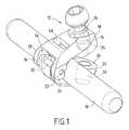
- FIG. 1is a fragmentary diagrammatic perspective view showing a vertebral fixing system of the invention and a rod,
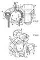
- FIG. 2is a diagrammatic view in vertical section of the subject matter of the invention mounted on a rod
- FIG. 3is a diagrammatic perspective view in section of the subject matter of the invention.
- FIG. 4is a diagrammatic view in elevation of the subject matter of the invention mounted on a vertebra.
- FIG. 1shows a vertebral fixing system of the invention mounted on a rod 10 .
- the vertebral fixing systemcomprises a connecting part 12 having two longitudinal members, of which a first longitudinal member 14 extends between a first end 16 and a second end 18 and a second longitudinal member 20 extends between a first end 22 and a second end 24 .
- the two longitudinal members 14 and 20are pivoted together at their first ends 16 and 22 for the purposes of mounting the system.
- the first end 16 of the longitudinal member 14has a notch 26 with two opposite edges 28 and 30 and between which the first end 22 of the other longitudinal member 20 may be inserted.
- a pivot pin 32passes through the two first ends 16 and 22 and is free to rotate in at least one of said ends 16 and/or 22 .
- the second end 18 of the first longitudinal member 14includes a bore 34 into which a screw 36 may be inserted.
- the second end 24 of the second longitudinal member 20comprises a thread 38 which is aligned with said bore 34 when the two longitudinal members are disposed facing each other, with the result that the screw 36 may be screwed into said thread 38 in order to drive the second ends 18 and 24 of the two longitudinal members 14 and 20 towards each other.
- FIG. 1also shows a first orifice 40 through which a ligature may be stretched. The method of connecting said ligature to said connecting part is described with reference to FIG. 2 .
- FIG. 2shows again the connecting part 12 consisting of the first longitudinal member 14 and the second longitudinal member 20 , said longitudinal members 14 and 20 pivoting about the pin 32 that joins them.
- the adjustable locking meansconsisting of said screws 36 passing through the bore 34 and screwed into the thread 38 immobilize said connecting part 12 relative to the rod 10 and fix in position a portion of a ligature 42 shown in part in FIG. 2 .
- the ligature 42consists of an elongate flexible member capable of conforming to the contour of the parts that it must connect.
- the ligature 42has a first end 44 that is ligated around the pin 32 and a free second end 46 that is inserted into a passage 48 between the rod 10 and the internal walls 50 and 52 of the longitudinal members 14 and 20 and the external wall of the rod 10 .
- the second longitudinal end 20includes a second orifice 54 through which said ligature 42 passes.
- the ligature 42may be formed into a loop 56 in which the transverse process is trapped.
- the ligature 42may also trap the rib.
- the middle parthas a first portion 56 through which said passage 48 passes and a second portion 58 adapted to bear directly on the rod.
- the passage 48which is symmetrical inside the first longitudinal member 14 , is produced by a groove formed in each of the two facing faces of the middle parts of the longitudinal members 14 and 20 .
- first portion 58 of the middle partforms an edge with cylindrical symmetry and that the corresponding second portion of the middle part of the first longitudinal member 14 forms a substantially cylindrical space 60 into which said rod 10 is inserted.
- FIG. 2shows that the second portion 58 of the middle part comes into contact with the rod and is adapted to bear on top of it and the first portion 56 presses the free second end of said ligature 42 against the rod 10 .
- the adjustable locking meanstherefore drive the longitudinal members 14 and 20 forcibly against the rod 10 and simultaneously against the ligature 42 , which is also forcibly pressed against the rod 10 .
- the passage 48has a section S 1 in the vicinity of the orifice 54 greater than the section S 2 in the vicinity of the first orifice 40 , the section of said passage 48 decreasing progressively in the direction from the second orifice 54 to the first orifice 40 .
- the ligature 42is therefore progressively compressed around a portion of the rod 10 with a pressure that increases in the direction from the second orifice 54 towards the first orifice 40 .
- FIG. 4shows a vertebral fixing system of the invention mounted on a vertebra having a transverse process. This figure shows again the rod 10 and the two longitudinal members 14 and 20 that grip it and press a portion of the ligature 42 against said rod 10 .
- the flexible ligature 42consists of a flexible strip of substantially constant width and thickness whose first end is ligated to the pin 32 , the ligature surrounding the transverse process of the vertebra being inserted through the connecting part 12 .
- the section of the flexible strip 42is substantially rectangular so that, the pin 32 and the rod 10 being substantially perpendicular to the transverse process, the ligature has to be partly twisted in order to insert it into the passage 48 and between the ligature 32 and the point at which it contacts the transverse process.
- the fixing system 12is fixed in position against the posterior wall 60 of the vertebra despite these partially twisted portions, the ligature 42 being forcibly tensioned by stretching the free second end 46 .
- the ligature 42is advantageously made from a flexible material such as polyester that may be lightly crushed locally to immobilize it with a clamping effect.
- a second aspect of the inventionrelates to a spine straightening assembly comprising a plurality of vertebral fixing systems conforming to the present invention and mounted on a plurality of successive vertebrae, on all the transverse processes of one lateral wall thereof, and connected to a single rod that is disposed substantially parallel to said spine.
- the transverse processes of a portion of the spinecan therefore be connected together by a single longitudinal rod, to fix them in position relative to each other, by means of the above vertebral fixing system.
Landscapes
- Health & Medical Sciences (AREA)
- Orthopedic Medicine & Surgery (AREA)
- Life Sciences & Earth Sciences (AREA)
- Neurology (AREA)
- Surgery (AREA)
- Heart & Thoracic Surgery (AREA)
- Engineering & Computer Science (AREA)
- Biomedical Technology (AREA)
- Nuclear Medicine, Radiotherapy & Molecular Imaging (AREA)
- Medical Informatics (AREA)
- Molecular Biology (AREA)
- Animal Behavior & Ethology (AREA)
- General Health & Medical Sciences (AREA)
- Public Health (AREA)
- Veterinary Medicine (AREA)
- Surgical Instruments (AREA)
- Prostheses (AREA)
- Medicines Containing Material From Animals Or Micro-Organisms (AREA)
Abstract
Description
This application is a continuation of U.S. patent application Ser. No. 13/248,497, filed Sep. 29, 2011, pending, entitled “VERTEBRAL FIXING SYSTEM,” which is a continuation of U.S. patent application Ser. No. 12/854,753, filed Aug. 11, 2010 now U.S. Pat. No. 8,323,319 entitled VERTEBRAL FIXING SYSTEM, which is a divisional of U.S. patent application Ser. No. 12/358,748, filed Jan. 23, 2009, now U.S. Pat. No. 7,959,654, entitled “VERTEBRAL FIXING SYSTEM,” which is a continuation of U.S. patent application Ser. No. 10/521,914, filed Jan. 20, 2005, now U.S. Pat. No. 7,481,828, entitled “VERTEBRAL FIXING SYSTEM,” which is a National Stage Entry under 35 U.S.C. 371 of International Application No. PCT/FR2003/02307, filed Jul. 22, 2003, entitled “VERTEBRAL FIXING SYSTEM,” which claims priority to French Application No. 02/09317, filed Jul. 23, 2002, now U.S. Pat. No. 2,842,724 entitled “SYSTEME DE FIXATION VERTEBRALE,” all of which are fully incorporated herein by reference.
The present invention relates to a vertebral fixing system adapted to be mounted on a vertebra, and to a spine-straightening assembly using the system.
One field of application that is envisaged, is particularly but not exclusively, the treatment of scoliosis or, more generally, the correction of abnormal curvatures of the spine.
The spine is formed of superposed vertebrae, normally aligned along a vertebral axis, from the lumbar vertebrae to the cervical vertebrae, and each having a posterior wall from which projects a spinous process and two lateral edges from the walls of which there project ribs and/or transverse processes. If the spine of a person has abnormal curvature, the vertebrae are inclined relative to each other and relative to said vertebral axis. The lateral edges of the vertebrae on one side are therefore closer together and form a concave shape while the lateral edges on the other side are farther apart and form a convex shape.
To straighten the vertebral column, the lateral edges of the vertebrae on the concave side are moved away from one another and supported at distances from one another substantially equivalent to the distances between the lateral edges on the other side. Devices known in the art are used thereafter to hold the vertebrae relative to one another, and comprise screws that are inserted into the vertebrae or hooks that are inserted along the internal wall of the spinal canal and rods adapted to connect the screws or hooks.
Pairs of hooks are generally inserted into each vertebra, one on each side, near the pedicle; they have heads that project from the posterior wall of the vertebra, one on each side of the spinous process. The heads are tulip-shaped, for example, and are adapted to receive a rod that is immobilized by a nut that is screwed onto the head and bears on the rod. The heads of the hooks situated on either side of the spinous process are connected together and fixed in position by two rods parallel to each other and to the axis of the spine.
However, using such hooks is difficult because the operative must not under any circumstances touch the spinal cord that extends along the centre of the spinal canal, since that would result in paralysis of the patient.
Using screws reduces the risks of the procedure. The screws also have tulip-shaped heads and are inserted in pairs into the pedicles on each side of the spinous process on the posterior wall of the vertebrae. The screws therefore constitute fixing points on the vertebrae for holding them relative to one another. However, they must be inserted into the pedicles of the vertebrae, which in some cases are small or have deteriorated.
A problem that arises, and that the present invention aims to solve, is that of providing fixing points when it is not possible to insert screws into the vertebrae in the abnormal curvature region and when using hooks is too dangerous.
To achieve the above object, a first aspect of the present invention proposes a vertebral fixing system that comprises: a connecting part adapted to face said rib and/or said transverse process and to be connected to said rod, an elongate flexible ligature adapted to connect together said connecting part and at least one rib and/or one transverse process, and adjustable locking means fastened to said connecting part and adapted to fix simultaneously in position said connecting part relative to said rod and at least one portion of said ligature relative to said connecting part, so as to prevent relative displacement of said rod and said vertebra in opposite directions.
Thus, one feature of the invention resides in the method of connecting said rod with said vertebrae using the connecting part that connects together the flexible ligature and said rod. The ligature, one end of which is connected to said rib and/or transverse process, is adapted to be immobilized in said connecting part by the adjustable locking means, which also fix said connecting part in position relative to said rod, with the result that relative displacement of said rod and said vertebra is prevented, at least in the opposite direction.
In a first embodiment of the invention, said connecting part includes a passage facing said rod and said ligature passes through the adjustable locking means to reduce the section of said passage in order to press said ligature against said rod and simultaneously to fix said connecting part and at least one portion of said ligature in position relative to said rod.
As a result of this feature of the invention, said ligature is adapted to be wedged between the wall of the passage in the connecting part and the wall of said rod and, at the same time, said connecting part is adapted to be fixed in position relative to said rod. As a result, it is only the action of the adjustable locking means that fixes the ligature in position and immobilizes the connecting part relative to said rod.
In one particularly advantageous embodiment of the invention, said ligature has a first end fastened to said connecting part and a free second end adapted to slide in said connecting part and to be formed into a loop, a portion of said ligature between said ends being adapted to be immobilized in translation relative to said connecting part by said adjustable locking means, whereby the loop has a particular length.
Thus, the ligature is formed of two sections. One end of the ligature is fixedly clipped to the connecting part, the ligature is then stretched around the rib and/or the spinous process, and the free second end of the ligature is then inserted into said connecting part. The first section of the ligature is the part that extends from the second end into contact with the rib and/or the transverse process and the second section is the part that extends from the rib and/or the transverse process to the connecting part. As a result, the free end may be stretched to hold said connecting part against the vertebra, said rod and said ligature being adapted to be locked together by adjustable locking means.
It is preferable if said connecting part comprises two longitudinal members whose first ends are connected together so that said members may pivot relative to each other and the middle parts of their two facing faces are adapted to bear on respective opposite sides of said rod, said adjustable locking means being adapted to drive the second ends of said longitudinal members forcibly towards each other and to fix them in position relative to each other so that said two members form a clamp and grip said rod, whereby said connecting part may be fixed in position relative to said rod.
The two longitudinal members articulated to each other at their first end form a clamp such that the two middle parts of the two facing faces may be driven towards each other and grip said rod. The adjustable locking means hold the two longitudinal members pressed onto said ligature and against said rod.
It is particularly advantageous if said second ends of the two longitudinal members have, facing each other, a bore in one and a thread in the other, so that a screw may be passed through said bore and screwed into said thread and form said adjustable locking means.
Turning the screw after it has been passed through the bore and screwed into the thread therefore forcibly drives the second ends towards each other. The force immobilizing said connecting part relative to said rod and said ligature is a function of the clamping force applied by said screw.
In one particularly advantageous embodiment, said first end of said ligature is fastened to the pivot of said longitudinal members. The tension force applied to said ligature is therefore substantially equally divided between the two first ends of said longitudinal members.
It is preferable if at least one of the middle parts of said two facing faces has a first portion through which said passage passes and a second portion adapted to bear against said rod. Accordingly, said second portion of said longitudinal members of the connecting part is adapted to bear on and to be in direct contact with said rod whereas the first portion of the middle parts presses said ligature against said rod. Said connecting part is therefore perfectly fastened to said rod and fixed in position relative to it and at the same time a portion of said ligature is perfectly wedged between said rod and the wall of said passage.
It is particularly advantageous if said passage extends between two orifices in said connecting part and opening to the outside of said part so that said ligature is able to slide through said part.
Said ligature is therefore perfectly guided inside said connecting part in said passage with the result that stretching of the free second end of said ligature cannot divert said ligature from said passage, regardless of the driving angle relative to said connecting part. During the stretching of said free end of said ligature, the adjustable locking means immobilize at least a portion of said ligature.
It is preferable if each of said middle parts of said two longitudinal members includes an orifice. Said free end of said ligature can then be inserted into one of the two orifices, stretched in the passage that extends between the two longitudinal members and said rod, and extracted via the second orifice so that it may be stretched. Pressing the two longitudinal members against said rod therefore immobilizes the ligature against the rod.
In one particularly advantageous embodiment, said passage has a section that decreases from one orifice to the other so as to be able to exert a progressive pressure on said ligature portion between said two orifices to press it against said rod.
Thus, according to this feature, the pressure of said ligature on the rod may be controlled by the adjustable locking means so that the free second end of said ligature may be forcibly stretched, to tension it. Once it has been tensioned, the adjustable locking means may be operated to immobilize the ligature completely relative to the rod and to immobilize the connecting part relative to the rod. The loop formed around the rib and/or the transverse process by said ligature is therefore of fixed size and maintains the tension in said connecting part facing the posterior wall of said vertebra.
Other features and advantages of the invention will emerge upon reading the description given hereinafter and with reference to the appended drawings of particular illustrative but non-limiting embodiments of the invention, in which drawings:
Theligature 42 consists of an elongate flexible member capable of conforming to the contour of the parts that it must connect.
Theligature 42 has afirst end 44 that is ligated around thepin 32 and a freesecond end 46 that is inserted into apassage 48 between therod 10 and theinternal walls longitudinal members rod 10. As shown inFIG. 2 , the secondlongitudinal end 20 includes asecond orifice 54 through which saidligature 42 passes. Moreover, as shown inFIG. 4 , theligature 42 may be formed into aloop 56 in which the transverse process is trapped. Clearly, where applicable, theligature 42 may also trap the rib.
As shown inFIG. 3 , which shows again the secondlongitudinal member 20, the middle part has afirst portion 56 through which saidpassage 48 passes and asecond portion 58 adapted to bear directly on the rod. Accordingly, thepassage 48, which is symmetrical inside the firstlongitudinal member 14, is produced by a groove formed in each of the two facing faces of the middle parts of thelongitudinal members
It is clear inFIG. 3 that thefirst portion 58 of the middle part forms an edge with cylindrical symmetry and that the corresponding second portion of the middle part of the firstlongitudinal member 14 forms a substantiallycylindrical space 60 into which saidrod 10 is inserted.
It is particularly advantageous if, as shown inFIG. 2 , thepassage 48 has a section S1 in the vicinity of theorifice 54 greater than the section S2 in the vicinity of thefirst orifice 40, the section of saidpassage 48 decreasing progressively in the direction from thesecond orifice 54 to thefirst orifice 40. Theligature 42 is therefore progressively compressed around a portion of therod 10 with a pressure that increases in the direction from thesecond orifice 54 towards thefirst orifice 40.
InFIG. 4 , theflexible ligature 42 consists of a flexible strip of substantially constant width and thickness whose first end is ligated to thepin 32, the ligature surrounding the transverse process of the vertebra being inserted through the connectingpart 12. The section of theflexible strip 42 is substantially rectangular so that, thepin 32 and therod 10 being substantially perpendicular to the transverse process, the ligature has to be partly twisted in order to insert it into thepassage 48 and between theligature 32 and the point at which it contacts the transverse process. The fixingsystem 12 is fixed in position against theposterior wall 60 of the vertebra despite these partially twisted portions, theligature 42 being forcibly tensioned by stretching the freesecond end 46.
Theligature 42 is advantageously made from a flexible material such as polyester that may be lightly crushed locally to immobilize it with a clamping effect.
A second aspect of the invention relates to a spine straightening assembly comprising a plurality of vertebral fixing systems conforming to the present invention and mounted on a plurality of successive vertebrae, on all the transverse processes of one lateral wall thereof, and connected to a single rod that is disposed substantially parallel to said spine. The transverse processes of a portion of the spine can therefore be connected together by a single longitudinal rod, to fix them in position relative to each other, by means of the above vertebral fixing system.
Claims (15)
1. A vertebral fixation system comprising:
a spinal rod configured to be positioned adjacent to a vertebral body;
a connecting part including a transverse passage receiving the spinal rod therethrough;
a flexible ligature having a first end region extending to a first end of the flexible ligature, a second end region extending to a second end of the flexible ligature, and an intermediate region extending between the first end region and the second end region;
wherein at least one of the first end region and the second end region extends from a first opening of the connecting part, and the intermediate region forms a loop extending from a second opening of the connecting part; and
an adjustable locking screw threadably engaged in a threaded bore hole of the connecting part;
wherein tightening the adjustable locking screw in the threaded bore hole causes the spinal rod to press against the flexible ligature without directly contacting the spinal rod.
2. The vertebral fixation system ofclaim 1 , wherein the adjustable locking screw does not directly contact the flexible ligature.
3. The vertebral fixation system ofclaim 1 , wherein tightening the adjustable locking screw fixes the rod from longitudinal movement through the transverse passage of the connecting part.
4. The vertebral fixation system ofclaim 3 , wherein the adjustable locking screw does not directly contact the spinal rod.
5. The vertebral fixation system ofclaim 1 , wherein the adjustable locking screw does not directly contact the flexible ligature.
6. The vertebral fixation system ofclaim 1 , wherein tightening the adjustable locking screw in the threaded bore hole presses the flexible ligature between the spinal rod and a surface of the connecting part.
7. The vertebral fixation system ofclaim 1 , wherein the connecting part includes a first longitudinal member and a second longitudinal member moveable relative to each other between a first position and a second position.
8. The vertebral fixation system ofclaim 7 , wherein the first longitudinal member and the second longitudinal member are connected by a hinge for movement between the first position and the second position.
9. A vertebral fixation system comprising:
a spinal rod configured to be positioned adjacent to a vertebral body;
a connecting part including a transverse passage receiving the spinal rod therethrough;
a flexible ligature having a portion extending through a passage of the connecting part, the flexible ligature forming a loop extending from the connecting part; and
an adjustable locking screw threadably engaged in a threaded bore hole of the connecting part;
wherein tightening the adjustable locking screw in the threaded bore hole presses the flexible ligature between the spinal rod and a surface of the connecting part without directly contacting the spinal rod.
10. The vertebral fixation system ofclaim 9 , wherein the adjustable locking screw does not directly contact the flexible ligature.
11. The vertebral fixation system ofclaim 9 , wherein tightening the adjustable locking screw fixes the rod from longitudinal movement through the transverse passage of the connecting part.
12. The vertebral fixation system ofclaim 11 , wherein the adjustable locking screw does not directly contact the flexible ligature.
13. A vertebral fixation system comprising:
a spinal rod configured to be positioned adjacent to a vertebral body;
a connecting part including a transverse passage receiving the spinal rod therethrough;
a flexible ligature having a portion extending through a passage of the connecting part, the flexible ligature forming a loop extending from the connecting part; and
an adjustable locking screw threadably engaged in a threaded bore hole of the connecting part;
wherein tightening the adjustable locking screw in the threaded bore hole simultaneously secures the flexible ligature and the spinal rod to the connecting part without directly contacting the spinal rod.
14. The vertebral fixation system ofclaim 13 , wherein the adjustable locking screw does not directly contact the flexible ligature.
15. The vertebral fixation system ofclaim 13 , wherein tightening the adjustable locking screw in the threaded bore hole presses the flexible ligature between the spinal rod and a surface of the connecting part.
Priority Applications (2)
| Application Number | Priority Date | Filing Date | Title |
|---|---|---|---|
| US14/339,901US9848921B2 (en) | 2002-07-23 | 2014-07-24 | Vertebral fixing system |
| US15/446,141US20170172626A1 (en) | 2002-07-23 | 2017-03-01 | Vertebral fixing system |
Applications Claiming Priority (9)
| Application Number | Priority Date | Filing Date | Title |
|---|---|---|---|
| FR02/09317 | 2002-07-23 | ||
| FR0209317AFR2842724B1 (en) | 2002-07-23 | 2002-07-23 | VERTEBRAL FASTENING SYSTEM |
| FR0209317 | 2002-07-23 | ||
| PCT/FR2003/002307WO2004010881A1 (en) | 2002-07-23 | 2003-07-22 | Vertebral fixing system |
| US10/521,914US7481828B2 (en) | 2002-07-23 | 2003-07-22 | Vertebral fixing system |
| US12/358,748US7959654B2 (en) | 2002-07-23 | 2009-01-23 | Vertebral fixing system |
| US12/854,753US8323319B2 (en) | 2002-07-23 | 2010-08-11 | Vertebral fixing system |
| US13/248,497US8801759B2 (en) | 2002-07-23 | 2011-09-29 | Vertebral fixing system |
| US14/339,901US9848921B2 (en) | 2002-07-23 | 2014-07-24 | Vertebral fixing system |
Related Parent Applications (1)
| Application Number | Title | Priority Date | Filing Date |
|---|---|---|---|
| US13/248,497ContinuationUS8801759B2 (en) | 2002-07-23 | 2011-09-29 | Vertebral fixing system |
Related Child Applications (1)
| Application Number | Title | Priority Date | Filing Date |
|---|---|---|---|
| US15/446,141ContinuationUS20170172626A1 (en) | 2002-07-23 | 2017-03-01 | Vertebral fixing system |
Publications (2)
| Publication Number | Publication Date |
|---|---|
| US20140336708A1 US20140336708A1 (en) | 2014-11-13 |
| US9848921B2true US9848921B2 (en) | 2017-12-26 |
Family
ID=30011403
Family Applications (6)
| Application Number | Title | Priority Date | Filing Date |
|---|---|---|---|
| US10/521,914Expired - LifetimeUS7481828B2 (en) | 2002-07-23 | 2003-07-22 | Vertebral fixing system |
| US12/358,748Expired - Fee RelatedUS7959654B2 (en) | 2002-07-23 | 2009-01-23 | Vertebral fixing system |
| US12/854,753Expired - Fee RelatedUS8323319B2 (en) | 2002-07-23 | 2010-08-11 | Vertebral fixing system |
| US13/248,497Expired - Fee RelatedUS8801759B2 (en) | 2002-07-23 | 2011-09-29 | Vertebral fixing system |
| US14/339,901Expired - LifetimeUS9848921B2 (en) | 2002-07-23 | 2014-07-24 | Vertebral fixing system |
| US15/446,141AbandonedUS20170172626A1 (en) | 2002-07-23 | 2017-03-01 | Vertebral fixing system |
Family Applications Before (4)
| Application Number | Title | Priority Date | Filing Date |
|---|---|---|---|
| US10/521,914Expired - LifetimeUS7481828B2 (en) | 2002-07-23 | 2003-07-22 | Vertebral fixing system |
| US12/358,748Expired - Fee RelatedUS7959654B2 (en) | 2002-07-23 | 2009-01-23 | Vertebral fixing system |
| US12/854,753Expired - Fee RelatedUS8323319B2 (en) | 2002-07-23 | 2010-08-11 | Vertebral fixing system |
| US13/248,497Expired - Fee RelatedUS8801759B2 (en) | 2002-07-23 | 2011-09-29 | Vertebral fixing system |
Family Applications After (1)
| Application Number | Title | Priority Date | Filing Date |
|---|---|---|---|
| US15/446,141AbandonedUS20170172626A1 (en) | 2002-07-23 | 2017-03-01 | Vertebral fixing system |
Country Status (10)
| Country | Link |
|---|---|
| US (6) | US7481828B2 (en) |
| EP (2) | EP1523280B1 (en) |
| JP (1) | JP4328292B2 (en) |
| KR (1) | KR101021418B1 (en) |
| AT (1) | ATE530133T1 (en) |
| AU (1) | AU2003267529B2 (en) |
| ES (2) | ES2376047T3 (en) |
| FR (1) | FR2842724B1 (en) |
| WO (1) | WO2004010881A1 (en) |
| ZA (1) | ZA200500576B (en) |
Cited By (1)
| Publication number | Priority date | Publication date | Assignee | Title |
|---|---|---|---|---|
| US11819255B2 (en) | 2019-10-07 | 2023-11-21 | Ortho Development Corporation | Tether tensioning instrumentation and related methods |
Families Citing this family (130)
| Publication number | Priority date | Publication date | Assignee | Title |
|---|---|---|---|---|
| FR2842724B1 (en) | 2002-07-23 | 2005-05-27 | Spine Next Sa | VERTEBRAL FASTENING SYSTEM |
| US7153325B2 (en)* | 2003-08-01 | 2006-12-26 | Ultra-Kinetics, Inc. | Prosthetic intervertebral disc and methods for using the same |
| US7744633B2 (en) | 2003-10-22 | 2010-06-29 | Pioneer Surgical Technology, Inc. | Crosslink for securing spinal rods |
| US7744635B2 (en)* | 2004-06-09 | 2010-06-29 | Spinal Generations, Llc | Spinal fixation system |
| US7658753B2 (en)* | 2004-08-03 | 2010-02-09 | K Spine, Inc. | Device and method for correcting a spinal deformity |
| US8114158B2 (en)* | 2004-08-03 | 2012-02-14 | Kspine, Inc. | Facet device and method |
| WO2006096381A2 (en)* | 2005-03-03 | 2006-09-14 | Accelerated Innovation Llc | Spinal stabilization using bone anchor seat and cross coupling with improved locking feature |
| WO2006096351A1 (en) | 2005-03-03 | 2006-09-14 | Accelerated Innovation, Llc | Spinal stabilization using bone anchor and anchor seat with tangential locking feature |
| FR2884136B1 (en)* | 2005-04-08 | 2008-02-22 | Spinevision Sa | INTERVERTEBRAL SURGICAL IMPLANT FORMING BALL |
| US9942511B2 (en) | 2005-10-31 | 2018-04-10 | Invention Science Fund I, Llc | Preservation/degradation of video/audio aspects of a data stream |
| US7628799B2 (en) | 2005-08-23 | 2009-12-08 | Aesculap Ag & Co. Kg | Rod to rod connector |
| FR2890850B1 (en)* | 2005-09-20 | 2009-04-17 | Abbott Spine Sa | VERTEBRAL FASTENING SYSTEM |
| FR2890849A1 (en)* | 2005-09-20 | 2007-03-23 | Abbott Spine Sa | Vertebral fixing system for e.g. scoliosis treatment, has connection part defining through path for elongated flexible link such that portions of link are engaged with path for defining link part and free ends |
| FR2890851B1 (en)* | 2005-09-21 | 2008-06-20 | Abbott Spine Sa | ANCILLARY TO TENSION A FLEXIBLE LINK. |
| EP1971282A2 (en)* | 2006-01-10 | 2008-09-24 | Life Spine, Inc. | Pedicle screw constructs and spinal rod attachment assemblies |
| US7803175B2 (en)* | 2006-01-30 | 2010-09-28 | Warsaw Orthopedic, Inc. | Devices and methods for attaching a rod to a vertebral member |
| US20070191844A1 (en)* | 2006-01-31 | 2007-08-16 | Sdgi Holdings, Inc. | In-series, dual locking mechanism device |
| US20080058808A1 (en) | 2006-06-14 | 2008-03-06 | Spartek Medical, Inc. | Implant system and method to treat degenerative disorders of the spine |
| EP2047813A1 (en) | 2007-10-11 | 2009-04-15 | Abbott Spine | Bone fixing system and method of use |
| US8361130B2 (en)* | 2006-10-06 | 2013-01-29 | Depuy Spine, Inc. | Bone screw fixation |
| US20080208223A1 (en)* | 2007-02-26 | 2008-08-28 | Paul Edward Kraemer | Cable clamping device and method of its use |
| US8048123B2 (en) | 2007-06-05 | 2011-11-01 | Spartek Medical, Inc. | Spine implant with a deflection rod system and connecting linkages and method |
| US8048115B2 (en)* | 2007-06-05 | 2011-11-01 | Spartek Medical, Inc. | Surgical tool and method for implantation of a dynamic bone anchor |
| US8114134B2 (en) | 2007-06-05 | 2012-02-14 | Spartek Medical, Inc. | Spinal prosthesis having a three bar linkage for motion preservation and dynamic stabilization of the spine |
| US8083772B2 (en)* | 2007-06-05 | 2011-12-27 | Spartek Medical, Inc. | Dynamic spinal rod assembly and method for dynamic stabilization of the spine |
| US8109970B2 (en) | 2007-06-05 | 2012-02-07 | Spartek Medical, Inc. | Deflection rod system with a deflection contouring shield for a spine implant and method |
| US8052722B2 (en) | 2007-06-05 | 2011-11-08 | Spartek Medical, Inc. | Dual deflection rod system for a dynamic stabilization and motion preservation spinal implantation system and method |
| US8092501B2 (en)* | 2007-06-05 | 2012-01-10 | Spartek Medical, Inc. | Dynamic spinal rod and method for dynamic stabilization of the spine |
| US8048128B2 (en) | 2007-06-05 | 2011-11-01 | Spartek Medical, Inc. | Revision system and method for a dynamic stabilization and motion preservation spinal implantation system and method |
| US8021396B2 (en) | 2007-06-05 | 2011-09-20 | Spartek Medical, Inc. | Configurable dynamic spinal rod and method for dynamic stabilization of the spine |
| EP2155086B1 (en) | 2007-06-06 | 2016-05-04 | K2M, Inc. | Medical device to correct deformity |
| ATE536824T1 (en)* | 2007-10-23 | 2011-12-15 | Zimmer Spine | FASTENING DEVICES AND STABILIZATION SYSTEMS WITH THESE FASTENING DEVICES |
| US8128635B2 (en)* | 2007-10-23 | 2012-03-06 | Zimmer Spine S.A.S. | Bone fixation tensioning tool and method |
| US8097024B2 (en) | 2008-02-26 | 2012-01-17 | Spartek Medical, Inc. | Load-sharing bone anchor having a deflectable post and method for stabilization of the spine |
| US8048125B2 (en)* | 2008-02-26 | 2011-11-01 | Spartek Medical, Inc. | Versatile offset polyaxial connector and method for dynamic stabilization of the spine |
| US8337536B2 (en) | 2008-02-26 | 2012-12-25 | Spartek Medical, Inc. | Load-sharing bone anchor having a deflectable post with a compliant ring and method for stabilization of the spine |
| US8007518B2 (en)* | 2008-02-26 | 2011-08-30 | Spartek Medical, Inc. | Load-sharing component having a deflectable post and method for dynamic stabilization of the spine |
| US8333792B2 (en)* | 2008-02-26 | 2012-12-18 | Spartek Medical, Inc. | Load-sharing bone anchor having a deflectable post and method for dynamic stabilization of the spine |
| US20100036437A1 (en)* | 2008-02-26 | 2010-02-11 | Spartek Medical, Inc. | Load-sharing bone anchor having a deflectable post with a compliant ring and method for stabilization of the spine |
| US8211155B2 (en)* | 2008-02-26 | 2012-07-03 | Spartek Medical, Inc. | Load-sharing bone anchor having a durable compliant member and method for dynamic stabilization of the spine |
| US8057517B2 (en) | 2008-02-26 | 2011-11-15 | Spartek Medical, Inc. | Load-sharing component having a deflectable post and centering spring and method for dynamic stabilization of the spine |
| US8083775B2 (en)* | 2008-02-26 | 2011-12-27 | Spartek Medical, Inc. | Load-sharing bone anchor having a natural center of rotation and method for dynamic stabilization of the spine |
| US8267979B2 (en)* | 2008-02-26 | 2012-09-18 | Spartek Medical, Inc. | Load-sharing bone anchor having a deflectable post and axial spring and method for dynamic stabilization of the spine |
| US20090248077A1 (en)* | 2008-03-31 | 2009-10-01 | Derrick William Johns | Hybrid dynamic stabilization |
| ATE515239T1 (en) | 2008-04-24 | 2011-07-15 | Zimmer Spine | SYSTEM FOR STABILIZING AT LEAST ONE SECTION OF THE SPINE |
| EP2303163B1 (en) | 2008-05-20 | 2011-11-23 | Zimmer Spine | System for stabilizing at least three vertebrae |
| WO2010048396A2 (en) | 2008-10-23 | 2010-04-29 | Linares Maedical Devices, Llc | Support insert associated with spinal vertebrae |
| FR2937531B1 (en) | 2008-10-23 | 2016-01-29 | Lotfi Miladi | SPINAL OSTEOSYNTHESIS SYSTEM |
| US8828058B2 (en) | 2008-11-11 | 2014-09-09 | Kspine, Inc. | Growth directed vertebral fixation system with distractible connector(s) and apical control |
| WO2010065795A1 (en) | 2008-12-03 | 2010-06-10 | Eminent Spine Llc | Spinal Cross-Connector and Method for Use of Same |
| IT1392200B1 (en)* | 2008-12-17 | 2012-02-22 | N B R New Biotechnology Res | MODULAR VERTEBRAL STABILIZER. |
| FR2940040B1 (en)* | 2008-12-19 | 2011-01-21 | Clariance | HINGE FASTENING SYSTEM FOR SPINAL OSTEOSYNTHESIS DEVICE. |
| US8357182B2 (en)* | 2009-03-26 | 2013-01-22 | Kspine, Inc. | Alignment system with longitudinal support features |
| US8231626B2 (en)* | 2009-05-12 | 2012-07-31 | Synthes Usa, Llc | Self-retaining cable tie |
| US20100318129A1 (en)* | 2009-06-16 | 2010-12-16 | Kspine, Inc. | Deformity alignment system with reactive force balancing |
| EP2279707A1 (en) | 2009-07-31 | 2011-02-02 | Zimmer Spine | Bone fixing system |
| US9168071B2 (en) | 2009-09-15 | 2015-10-27 | K2M, Inc. | Growth modulation system |
| EP2316363A1 (en) | 2009-10-27 | 2011-05-04 | Zimmer Spine | Bone holding device |
| US20110118783A1 (en)* | 2009-11-16 | 2011-05-19 | Spartek Medical, Inc. | Load-sharing bone anchor having a flexible post and method for dynamic stabilization of the spine |
| US8328849B2 (en)* | 2009-12-01 | 2012-12-11 | Zimmer Gmbh | Cord for vertebral stabilization system |
| CN102695465A (en) | 2009-12-02 | 2012-09-26 | 斯帕泰克医疗股份有限公司 | Low profile spinal prosthesis incorporating a bone anchor having a deflectable post and a compound spinal rod |
| FR2954905B1 (en) | 2010-01-06 | 2012-12-28 | Implanet | DEVICE FOR FIXING VERTEBRAL |
| US20110301644A1 (en)* | 2010-06-08 | 2011-12-08 | Zimmer Spine | Spinal stabilization system |
| US20110307015A1 (en) | 2010-06-10 | 2011-12-15 | Spartek Medical, Inc. | Adaptive spinal rod and methods for stabilization of the spine |
| EP2422728B1 (en) | 2010-08-25 | 2013-01-30 | Zimmer Spine | Anchor for attachment to a bony structure |
| EP2471476A1 (en)* | 2010-11-10 | 2012-07-04 | Zimmer Spine | Bone anchor |
| USD668338S1 (en)* | 2010-11-11 | 2012-10-02 | Gautheir Biomedical, Inc. | Tool implement release collar |
| EP2460482A1 (en)* | 2010-12-03 | 2012-06-06 | Zimmer Spine | Rod holding device |
| US9084644B2 (en) | 2011-02-02 | 2015-07-21 | DePuy Synthes Products, Inc. | Bone fixation assembly |
| US8740949B2 (en) | 2011-02-24 | 2014-06-03 | Spinal Elements, Inc. | Methods and apparatus for stabilizing bone |
| US8992579B1 (en)* | 2011-03-08 | 2015-03-31 | Nuvasive, Inc. | Lateral fixation constructs and related methods |
| CA2831081A1 (en)* | 2011-04-07 | 2012-10-11 | Mike Hammer | Clamp for spinal cross connecting device |
| JP6158176B2 (en) | 2011-06-03 | 2017-07-05 | ケイツーエム インコーポレイテッドK2M,Inc. | Spine correction system |
| US9005249B2 (en) | 2011-07-11 | 2015-04-14 | Life Spine, Inc. | Spinal rod connector assembly |
| EP2734135B1 (en) | 2011-07-21 | 2018-03-21 | Zimmer Spine | Spinal rod fixing device |
| US8636770B2 (en) | 2011-08-08 | 2014-01-28 | Zimmer Spine, Inc. | Bone anchoring device |
| WO2013040456A1 (en)* | 2011-09-14 | 2013-03-21 | Band-Lok, Llc | Tether clamp and implantation system |
| USD739935S1 (en) | 2011-10-26 | 2015-09-29 | Spinal Elements, Inc. | Interbody bone implant |
| FR2981841B1 (en)* | 2011-10-28 | 2013-12-20 | Implanet | DEVICE FOR TENSIONING A SOFT BAND AND COMPRISING ASSEMBLY SUCH DEVICE WITH FLEXIBLE BAND |
| US9451987B2 (en) | 2011-11-16 | 2016-09-27 | K2M, Inc. | System and method for spinal correction |
| WO2014172632A2 (en) | 2011-11-16 | 2014-10-23 | Kspine, Inc. | Spinal correction and secondary stabilization |
| US9468468B2 (en) | 2011-11-16 | 2016-10-18 | K2M, Inc. | Transverse connector for spinal stabilization system |
| US8920472B2 (en) | 2011-11-16 | 2014-12-30 | Kspine, Inc. | Spinal correction and secondary stabilization |
| US9468469B2 (en) | 2011-11-16 | 2016-10-18 | K2M, Inc. | Transverse coupler adjuster spinal correction systems and methods |
| GB2497782A (en) | 2011-12-20 | 2013-06-26 | Vincent Lefauconnier | Bone fixation device |
| US8430916B1 (en) | 2012-02-07 | 2013-04-30 | Spartek Medical, Inc. | Spinal rod connectors, methods of use, and spinal prosthesis incorporating spinal rod connectors |
| US9060815B1 (en) | 2012-03-08 | 2015-06-23 | Nuvasive, Inc. | Systems and methods for performing spine surgery |
| FR2988992B1 (en)* | 2012-04-04 | 2015-03-20 | Medicrea International | MATERIAL OF VERTEBRAL OSTEOSYNTHESIS |
| US8945188B2 (en)* | 2012-04-06 | 2015-02-03 | William Alan Rezach | Spinal correction system and method |
| US8870881B2 (en) | 2012-04-06 | 2014-10-28 | Warsaw Orthopedic, Inc. | Spinal correction system and method |
| US8771319B2 (en) | 2012-04-16 | 2014-07-08 | Aesculap Implant Systems, Llc | Rod to rod cross connector |
| US8828056B2 (en) | 2012-04-16 | 2014-09-09 | Aesculap Implant Systems, Llc | Rod to rod cross connector |
| EP2664291B1 (en)* | 2012-05-16 | 2016-07-20 | Stryker European Holdings I, LLC | Surgical assembly |
| EP2668921B1 (en)* | 2012-06-01 | 2015-08-12 | Zimmer Spine | Device for fixing a bony structure to a support member |
| US20140148854A1 (en) | 2012-11-28 | 2014-05-29 | Zimmer Spine, Inc. | Vertebral fixation system |
| EP2762095B1 (en) | 2013-01-31 | 2016-05-25 | Zimmer Spine | Device for fixing a bony structure to a support member |
| US10034692B2 (en)* | 2013-03-05 | 2018-07-31 | Globus Medical, Inc. | Elastic member clamps |
| US10548644B2 (en) | 2013-03-05 | 2020-02-04 | Globus Medical, Inc. | Elastic member clamps |
| US9675386B2 (en)* | 2013-03-11 | 2017-06-13 | K2M, Inc. | Flexible fastening system |
| US9421044B2 (en) | 2013-03-14 | 2016-08-23 | Spinal Elements, Inc. | Apparatus for bone stabilization and distraction and methods of use |
| US9468471B2 (en) | 2013-09-17 | 2016-10-18 | K2M, Inc. | Transverse coupler adjuster spinal correction systems and methods |
| US9839450B2 (en) | 2013-09-27 | 2017-12-12 | Spinal Elements, Inc. | Device and method for reinforcement of a facet |
| US9456855B2 (en) | 2013-09-27 | 2016-10-04 | Spinal Elements, Inc. | Method of placing an implant between bone portions |
| US9517089B1 (en) | 2013-10-08 | 2016-12-13 | Nuvasive, Inc. | Bone anchor with offset rod connector |
| FR3012032B1 (en) | 2013-10-18 | 2015-12-11 | Implanet | DEVICE AND SYSTEM FOR VERTICAL FASTENING FOR HOLDING A VERTEBRA ON A ROD, METHOD OF BLOCKING A LOOP WITH SUCH A DEVICE. |
| US9402666B2 (en) | 2014-04-30 | 2016-08-02 | King Faisal Specialist Hospital & Research Centre | Vertebral fixation device |
| US9603646B2 (en) | 2014-05-30 | 2017-03-28 | DePuy Synthes Products, Inc. | Bone fixation assembly |
| US11478275B2 (en)* | 2014-09-17 | 2022-10-25 | Spinal Elements, Inc. | Flexible fastening band connector |
| US9931138B2 (en) | 2014-10-15 | 2018-04-03 | Globus Medical, Inc. | Orthopedic extendable rods |
| AU2016212009C1 (en) | 2015-01-27 | 2021-02-25 | Spinal Elements, Inc. | Facet joint implant |
| US9795421B2 (en) | 2015-07-07 | 2017-10-24 | K2M, Inc. | Spinal construct with flexible member |
| US9924976B2 (en) | 2015-09-24 | 2018-03-27 | Warsaw Orthopedic, Inc. | Spinal implant system and method |
| EP3525699B1 (en) | 2016-10-11 | 2023-07-26 | K2M, Inc. | Spinal implant |
| US10307186B2 (en) | 2016-12-02 | 2019-06-04 | Nuvasive, Inc. | Surgical band clamp system |
| WO2018191184A1 (en)* | 2017-04-10 | 2018-10-18 | Life Spine, Inc. (A Delaware Corporation) | Laminar fixation clamp |
| US10736682B2 (en) | 2017-04-10 | 2020-08-11 | Life Spine, Inc. | Laminar fixation device and method |
| US10292737B2 (en) | 2017-06-07 | 2019-05-21 | Warsaw Orthopedic, Inc. | Spinal implant system and method |
| US11071569B2 (en) | 2017-08-10 | 2021-07-27 | Ortho Development Corporation | Nesting tether clamping assemblies and related methods and apparatus |
| US11051857B2 (en) | 2017-08-10 | 2021-07-06 | Ortho Development Corporation | Tether clamping assemblies and related methods and apparatus |
| US10869696B2 (en)* | 2019-01-30 | 2020-12-22 | Medos International Sarl | Surgical device for spinal fixation |
| US11185319B2 (en) | 2019-02-11 | 2021-11-30 | Warsaw Orthopedic, Inc. | Surgical distractor and method |
| US11116550B2 (en) | 2019-04-26 | 2021-09-14 | Warsaw Orthopedic, Inc. | Spinal implant system and method |
| BR112021022695A2 (en) | 2019-05-22 | 2021-12-28 | Spinal Elements Inc | Bone tethering and bone tethering inserter |
| US11457959B2 (en) | 2019-05-22 | 2022-10-04 | Spinal Elements, Inc. | Bone tie and bone tie inserter |
| US20210121203A1 (en)* | 2019-10-29 | 2021-04-29 | Globus Medical, Inc. | Sublaminar band clamp |
| WO2021163313A1 (en) | 2020-02-14 | 2021-08-19 | Spinal Elements, Inc. | Bone tie methods |
| US11284924B1 (en) | 2020-12-16 | 2022-03-29 | Warsaw Orthopedic, Inc | Adjustable spinal implant, system and method |
| EP4029464B1 (en) | 2021-01-15 | 2024-03-27 | NSpine GmbH | Spinal fixation system |
| US11350969B1 (en) | 2021-02-02 | 2022-06-07 | Warsaw Orthopedic, Inc. | Rotatable spinal implant, system, and method |
| US12369952B2 (en) | 2021-12-10 | 2025-07-29 | Spinal Elements, Inc. | Bone tie and portal |
Citations (103)
| Publication number | Priority date | Publication date | Assignee | Title |
|---|---|---|---|---|
| US902040A (en) | 1906-03-12 | 1908-10-27 | Homer W Wyckoff | Wire-connector. |
| US1346940A (en) | 1919-10-28 | 1920-07-20 | Asa W Collins | Apparatus for binding fractured bones |
| FR26156E (en) | 1922-03-30 | 1923-09-05 | Ligating device | |
| US2049361A (en) | 1934-10-27 | 1936-07-28 | Ericsson Ernst Axel Johan | Wire or ribbon tightening apparatus |
| US4570618A (en) | 1983-11-23 | 1986-02-18 | Henry Ford Hospital | Intervertebral body wire stabilization |
| US5030220A (en) | 1990-03-29 | 1991-07-09 | Advanced Spine Fixation Systems Incorporated | Spine fixation system |
| GB2269753A (en) | 1992-08-19 | 1994-02-23 | Surgicarft Ltd | Surgical implants,tensioning tools and anchorage inserter |
| US5304178A (en) | 1992-05-29 | 1994-04-19 | Acromed Corporation | Sublaminar wire |
| WO1994016635A1 (en) | 1993-01-19 | 1994-08-04 | Jbs Sa | Spinal osteosynthesis device |
| US5356412A (en) | 1992-10-09 | 1994-10-18 | United States Surgical Corporation | Sternum buckle with rotational engagement and method of closure |
| FR2704745A1 (en) | 1993-05-07 | 1994-11-10 | Erpios | Device for connecting the ends of a ligament for osteosynthesis, in particular for vertebral osteosynthesis. |
| US5413576A (en) | 1993-02-10 | 1995-05-09 | Rivard; Charles-Hilaire | Apparatus for treating spinal disorder |
| US5449361A (en) | 1993-04-21 | 1995-09-12 | Amei Technologies Inc. | Orthopedic cable tensioner |
| FR2722088A1 (en) | 1994-07-08 | 1996-01-12 | Cahlik Marc Andre | Surgical implant for stabilising intervertebral spaces |
| US5609634A (en) | 1992-07-07 | 1997-03-11 | Voydeville; Gilles | Intervertebral prosthesis making possible rotatory stabilization and flexion/extension stabilization |
| EP0780096A1 (en) | 1995-12-22 | 1997-06-25 | Transystème S.A. | Binding strap for medical uses and fixing device |
| US5667508A (en) | 1996-05-01 | 1997-09-16 | Fastenetix, Llc | Unitary locking cap for use with a pedicle screw |
| US5669917A (en) | 1994-02-24 | 1997-09-23 | Lasersurge, Inc. | Surgical crimping device and method of use |
| US5702399A (en) | 1996-05-16 | 1997-12-30 | Pioneer Laboratories, Inc. | Surgical cable screw connector |
| US5720751A (en) | 1996-11-27 | 1998-02-24 | Jackson; Roger P. | Tools for use in seating spinal rods in open ended implants |
| US5772663A (en) | 1994-02-17 | 1998-06-30 | Whiteside; Leo A. | Surgical device for banding bone with cable |
| DE19716504A1 (en) | 1997-04-19 | 1998-12-03 | Hinze Manfred Dr Med Habil | Compression hoop for applying metal band around bone |
| USRE36221E (en) | 1989-02-03 | 1999-06-01 | Breard; Francis Henri | Flexible inter-vertebral stabilizer as well as process and apparatus for determining or verifying its tension before installation on the spinal column |
| US5935133A (en) | 1997-08-26 | 1999-08-10 | Spinal Concepts, Inc. | Surgical cable system and method |
| US5938663A (en) | 1995-03-06 | 1999-08-17 | Stryker France, S.A. | Spinal instruments, particularly for a rod |
| US6053921A (en) | 1997-08-26 | 2000-04-25 | Spinal Concepts, Inc. | Surgical cable system and method |
| US6086590A (en)* | 1999-02-02 | 2000-07-11 | Pioneer Laboratories, Inc. | Cable connector for orthopaedic rod |
| US6099527A (en) | 1998-04-30 | 2000-08-08 | Spinal Concepts, Inc. | Bone protector and method |
| US6146386A (en) | 1999-02-04 | 2000-11-14 | Sdgi Holdings, Inc. | Cable operated bone anchor compressor |
| US6179838B1 (en) | 1998-02-24 | 2001-01-30 | Daniel Fiz | Bone fixation arrangements and method |
| FR2799948A1 (en) | 1999-10-22 | 2001-04-27 | Transco Esquisse | Connecting bar esp for lumbar arthrodesis has lateral rod fixings and central anchor for interspinal prosthesis |
| US6228086B1 (en) | 1997-03-19 | 2001-05-08 | Stryker Trauma-Selzach Ag | Modular intramedullary nail |
| US6228096B1 (en) | 1999-03-31 | 2001-05-08 | Sam R. Marchand | Instrument and method for manipulating an operating member coupled to suture material while maintaining tension on the suture material |
| US6241740B1 (en) | 1998-04-09 | 2001-06-05 | Origin Medsystems, Inc. | System and method of use for ligating and cutting tissue |
| WO2001054599A1 (en) | 2000-01-31 | 2001-08-02 | Sven Olerud | Locking device and method for using this device |
| US6277120B1 (en) | 2000-09-20 | 2001-08-21 | Kevin Jon Lawson | Cable-anchor system for spinal fixation |
| US6299613B1 (en) | 1999-04-23 | 2001-10-09 | Sdgi Holdings, Inc. | Method for the correction of spinal deformities through vertebral body tethering without fusion |
| JP2001299770A (en) | 2000-04-20 | 2001-10-30 | Azwell Inc | Clip for bone fixing string |
| US6309390B1 (en) | 1997-04-04 | 2001-10-30 | Stryker France S.A. | Device for backbone osteosynthesis with offset intervertebral fixing rod |
| WO2002007621A1 (en) | 2000-07-25 | 2002-01-31 | Spine Next | Semirigid linking piece for stabilising the spine |
| WO2002007622A1 (en) | 2000-07-25 | 2002-01-31 | Spine Next | Flexible linking piece for stabilising the spine |
| WO2002009604A1 (en) | 2000-08-02 | 2002-02-07 | Depuy International Limited | Surgical fixings |
| US6352557B1 (en) | 1999-08-13 | 2002-03-05 | Bret A. Ferree | Treating degenerative disc disease through transplantion of extracellular nucleus pulposus matrix and autograft nucleus pulposus cells |
| WO2002017803A2 (en) | 2000-09-01 | 2002-03-07 | Hôpital Sainte-Justine | Mobile dynamic system for treating spinal disorder |
| US20020035366A1 (en)* | 2000-09-18 | 2002-03-21 | Reto Walder | Pedicle screw for intervertebral support elements |
| FR2817929A1 (en) | 2000-12-07 | 2002-06-14 | Spine Next Sa | DEVICE FOR FIXING A ROD AND A SPHERICAL SYMMETRY SCREW HEAD |
| WO2002051326A1 (en) | 2000-12-22 | 2002-07-04 | Spine Next | Intervertebral implant with deformable wedge |
| US6419702B1 (en) | 1999-08-13 | 2002-07-16 | Bret A. Ferree | Treating degenerative disc disease through transplantation of the nucleus pulposis |
| US20020116013A1 (en) | 2000-10-24 | 2002-08-22 | Gleason Joseph E. | Tension band clip |
| US6447518B1 (en) | 1995-07-18 | 2002-09-10 | William R. Krause | Flexible shaft components |
| WO2002071960A1 (en) | 2001-03-13 | 2002-09-19 | Spine Next | Self locking fixable intervertebral implant |
| US6478798B1 (en) | 2001-05-17 | 2002-11-12 | Robert S. Howland | Spinal fixation apparatus and methods for use |
| US20020198538A1 (en) | 2001-06-25 | 2002-12-26 | Kortenbach Juergen A. | Surgical device having a handle adapted to impart tensile and compressive forces to elements at a distal end of the device |
| WO2003007829A1 (en) | 2001-07-20 | 2003-01-30 | Spinal Concepts, Inc. | Spinal stabilization system and method |
| US6514255B1 (en)* | 2000-02-25 | 2003-02-04 | Bret Ferree | Sublaminar spinal fixation apparatus |
| US6520965B2 (en)* | 2001-05-23 | 2003-02-18 | Alan Chervitz | Apparatus and method for orthopedic fixation |
| US6547790B2 (en) | 2000-08-08 | 2003-04-15 | Depuy Acromed, Inc. | Orthopaedic rod/plate locking mechanisms and surgical methods |
| US6547770B2 (en) | 2000-04-14 | 2003-04-15 | Aiolos Systems Aktiebolag (Ab) | Ophthalmic dispensing device |
| US6569164B1 (en) | 1998-04-29 | 2003-05-27 | Stryker Spine | Spinal osteosynthesis system for anterior fixation |
| US6569171B2 (en) | 2001-02-28 | 2003-05-27 | Microline, Inc. | Safety locking mechanism for a medical clip device |
| US6605091B1 (en) | 2000-06-30 | 2003-08-12 | Pioneer Laboratories, Inc. | Surgical cable assembly and method |
| US20030195628A1 (en) | 1994-05-06 | 2003-10-16 | Qi-Bin Bao | Method of making an intervertebral disc prosthesis |
| US6641584B2 (en) | 2000-09-22 | 2003-11-04 | Showa Ika Kohgyo Co., Ltd. | Hook cable for fixing atlantoaxial joint and system for fixing the same |
| US6656179B1 (en) | 1999-10-18 | 2003-12-02 | Bernd Schaefer | Bone plate |
| WO2003103519A2 (en) | 2002-06-06 | 2003-12-18 | Grampian University Hospitals Nhs Trust | Device |
| WO2004010881A1 (en) | 2002-07-23 | 2004-02-05 | Spine Next | Vertebral fixing system |
| US6689140B2 (en) | 2000-10-02 | 2004-02-10 | Howmedica Osteonics Corp. | System and method for spinal reconstruction |
| US6695852B2 (en) | 2001-10-31 | 2004-02-24 | Spineology, Inc. | Tension tools for tension band clip |
| US6723335B1 (en) | 2000-04-07 | 2004-04-20 | Jeffrey William Moehlenbruck | Methods and compositions for treating intervertebral disc degeneration |
| US20040087979A1 (en) | 2002-03-25 | 2004-05-06 | Field Frederic P. | Surgical suturing instrument and method of use |
| US20040097942A1 (en) | 2002-08-28 | 2004-05-20 | Allen C. Wayne | System, methods, and apparatuses for clamping and reclamping an orthopedic surgical cable |
| US6746452B2 (en) | 1997-03-14 | 2004-06-08 | Finsbury (Development) Limited | Prosthetic implant and surgical tool |
| US20040138666A1 (en) | 2003-01-10 | 2004-07-15 | Molz Fred J. | Flexible member tensioning instruments and methods |
| US6773438B1 (en) | 2000-10-19 | 2004-08-10 | Ethicon Endo-Surgery | Surgical instrument having a rotary lockout mechanism |
| WO2005020860A2 (en) | 2003-08-21 | 2005-03-10 | Abbott Spine | Intervertebral implant for the lumbosacral articulation |
| US20050070958A1 (en) | 2003-09-29 | 2005-03-31 | Swayze Jeffrey S. | Surgical stapling instrument incorporating a multistroke firing position indicator and retraction mechanism |
| US20050085815A1 (en) | 2003-10-17 | 2005-04-21 | Biedermann Motech Gmbh | Rod-shaped implant element for application in spine surgery or trauma surgery, stabilization apparatus comprising said rod-shaped implant element, and production method for the rod-shaped implant element |
| US20050131404A1 (en) | 2002-02-25 | 2005-06-16 | Keyvan Mazda | Device for the connection between a shaft and a screw head with spherical symmetry |
| US20050154403A1 (en) | 2004-01-14 | 2005-07-14 | Lsi Solutions, Inc. | Running stitch suturing device |
| US20050177156A1 (en) | 2003-05-02 | 2005-08-11 | Timm Jens P. | Surgical implant devices and systems including a sheath member |
| FR2867057A1 (en) | 2004-03-02 | 2005-09-09 | Spinevision | Connecting element, useful for a spinal fixing system to connect two entire implantable connection bodies comprises a cable and a polymer envelope surrounding the cable |
| FR2870718A1 (en) | 2004-05-25 | 2005-12-02 | Spine Next Sa | TREATMENT ASSEMBLY FOR THE DEGENERATION OF AN INTERVERTEBRAL DISC |
| US20050273983A1 (en) | 2004-06-09 | 2005-12-15 | Kinamed, Inc. | High tension, surgical cable lock |
| WO2005120277A1 (en) | 2004-05-11 | 2005-12-22 | Abbott Spine | Self-locking device for fixing an intervertebral implant |
| WO2006034423A2 (en) | 2004-09-23 | 2006-03-30 | St. Francis Medical Technologies, Inc. | Interspinous process implant including a binder and method of implantation |
| WO2006106268A2 (en) | 2005-04-07 | 2006-10-12 | Abbott Spine | Intervertebral implant for lumbrosacral joint |
| WO2006106246A2 (en) | 2005-04-08 | 2006-10-12 | Spinevision | Surgical intervertebral implant forming a swivel joint |
| US20060235387A1 (en) | 2005-04-15 | 2006-10-19 | Sdgi Holdings, Inc. | Transverse process/laminar spacer |
| US20060235391A1 (en) | 2005-03-08 | 2006-10-19 | Sutterlin Chester Iii | Facet joint stabilization |
| US20070016190A1 (en) | 2005-07-14 | 2007-01-18 | Medical Device Concepts Llc | Dynamic spinal stabilization system |
| WO2007023240A2 (en) | 2005-08-26 | 2007-03-01 | Abbott Spine | Intervertebral implant for the lumbosacral joint |
| FR2890851A1 (en) | 2005-09-21 | 2007-03-23 | Abbott Spine Sa | ANCILLARY TO TENSION A FLEXIBLE LINK. |
| FR2890850A1 (en) | 2005-09-20 | 2007-03-23 | Abbott Spine Sa | Vertebral fixing system for e.g. scoliosis treatment, has connection part defining through path for elongated flexible link such that portions of link are engaged with path for defining link part and free ends |
| US20070088359A1 (en) | 2005-02-07 | 2007-04-19 | Woods Richard W | Universal dynamic spine stabilization device and method of use |
| EP1815812A1 (en) | 2006-02-03 | 2007-08-08 | Spinelab AG | Spinal implant |
| FR2897771A1 (en) | 2006-02-28 | 2007-08-31 | Abbott Spine Sa | Intervertebral implant for e.g. spines of patient`s vertebrae, has recesses defined by extensions extending respective insertion faces, where height of one of extensions with respect to base wall is lesser than height of other extension |
| US20070299445A1 (en) | 2006-06-22 | 2007-12-27 | Shadduck John H | Spine treatment devices and methods |
| US20080033557A1 (en) | 2004-05-17 | 2008-02-07 | Abbott Spine | Intervertebral Spacer for Cervical Vertebrae |
| US20080125780A1 (en) | 2006-11-28 | 2008-05-29 | Ferree Bret A | Methods of posterior fixation and stabilization of a spinal segment |
| US20080140133A1 (en) | 2006-12-08 | 2008-06-12 | Randall Noel Allard | Methods and Devices for Treating a Multi-Level Spinal Deformity |
| US20080208256A1 (en) | 2006-11-10 | 2008-08-28 | Lanx, Llc | Pedicle based spinal stabilization with adjacent vertebral body support |
| US7699874B2 (en) | 2006-03-01 | 2010-04-20 | Warsaw Orthopedic, Inc. | Low profile spinal rod connector system |
| US7959554B2 (en) | 2004-03-29 | 2011-06-14 | Cook Biotech Incorporated | Medical graft products with differing regions and methods and systems for producing the same |
Family Cites Families (2)
| Publication number | Priority date | Publication date | Assignee | Title |
|---|---|---|---|---|
| FR522040A (en) | 1920-08-07 | 1921-07-24 | Auguste Henri Contassot | Ligating device |
| US20040128666A1 (en)* | 2002-12-28 | 2004-07-01 | Alex Elkin | Distributed Dynamic Process Control System |
- 2002
- 2002-07-23FRFR0209317Apatent/FR2842724B1/ennot_activeExpired - Fee Related
- 2003
- 2003-07-22ESES03748221Tpatent/ES2376047T3/ennot_activeExpired - Lifetime
- 2003-07-22WOPCT/FR2003/002307patent/WO2004010881A1/enactiveApplication Filing
- 2003-07-22ATAT03748221Tpatent/ATE530133T1/ennot_activeIP Right Cessation
- 2003-07-22KRKR1020057001238Apatent/KR101021418B1/ennot_activeExpired - Fee Related
- 2003-07-22EPEP03748221Apatent/EP1523280B1/ennot_activeExpired - Lifetime
- 2003-07-22ESES11178875Tpatent/ES2421620T3/ennot_activeExpired - Lifetime
- 2003-07-22AUAU2003267529Apatent/AU2003267529B2/ennot_activeCeased
- 2003-07-22JPJP2004523862Apatent/JP4328292B2/ennot_activeExpired - Fee Related
- 2003-07-22USUS10/521,914patent/US7481828B2/ennot_activeExpired - Lifetime
- 2003-07-22EPEP11178875.8Apatent/EP2392277B1/ennot_activeExpired - Lifetime
- 2006
- 2006-01-20ZAZA200500576Apatent/ZA200500576B/enunknown
- 2009
- 2009-01-23USUS12/358,748patent/US7959654B2/ennot_activeExpired - Fee Related
- 2010
- 2010-08-11USUS12/854,753patent/US8323319B2/ennot_activeExpired - Fee Related
- 2011
- 2011-09-29USUS13/248,497patent/US8801759B2/ennot_activeExpired - Fee Related
- 2014
- 2014-07-24USUS14/339,901patent/US9848921B2/ennot_activeExpired - Lifetime
- 2017
- 2017-03-01USUS15/446,141patent/US20170172626A1/ennot_activeAbandoned
Patent Citations (121)
| Publication number | Priority date | Publication date | Assignee | Title |
|---|---|---|---|---|
| US902040A (en) | 1906-03-12 | 1908-10-27 | Homer W Wyckoff | Wire-connector. |
| US1346940A (en) | 1919-10-28 | 1920-07-20 | Asa W Collins | Apparatus for binding fractured bones |
| FR26156E (en) | 1922-03-30 | 1923-09-05 | Ligating device | |
| US2049361A (en) | 1934-10-27 | 1936-07-28 | Ericsson Ernst Axel Johan | Wire or ribbon tightening apparatus |
| US4570618A (en) | 1983-11-23 | 1986-02-18 | Henry Ford Hospital | Intervertebral body wire stabilization |
| USRE36221E (en) | 1989-02-03 | 1999-06-01 | Breard; Francis Henri | Flexible inter-vertebral stabilizer as well as process and apparatus for determining or verifying its tension before installation on the spinal column |
| US5030220A (en) | 1990-03-29 | 1991-07-09 | Advanced Spine Fixation Systems Incorporated | Spine fixation system |
| US5304178A (en) | 1992-05-29 | 1994-04-19 | Acromed Corporation | Sublaminar wire |
| US5609634A (en) | 1992-07-07 | 1997-03-11 | Voydeville; Gilles | Intervertebral prosthesis making possible rotatory stabilization and flexion/extension stabilization |
| GB2269753A (en) | 1992-08-19 | 1994-02-23 | Surgicarft Ltd | Surgical implants,tensioning tools and anchorage inserter |
| US5356412A (en) | 1992-10-09 | 1994-10-18 | United States Surgical Corporation | Sternum buckle with rotational engagement and method of closure |
| WO1994016635A1 (en) | 1993-01-19 | 1994-08-04 | Jbs Sa | Spinal osteosynthesis device |
| US5413576A (en) | 1993-02-10 | 1995-05-09 | Rivard; Charles-Hilaire | Apparatus for treating spinal disorder |
| US5449361A (en) | 1993-04-21 | 1995-09-12 | Amei Technologies Inc. | Orthopedic cable tensioner |
| FR2704745A1 (en) | 1993-05-07 | 1994-11-10 | Erpios | Device for connecting the ends of a ligament for osteosynthesis, in particular for vertebral osteosynthesis. |
| US5772663A (en) | 1994-02-17 | 1998-06-30 | Whiteside; Leo A. | Surgical device for banding bone with cable |
| US5669917A (en) | 1994-02-24 | 1997-09-23 | Lasersurge, Inc. | Surgical crimping device and method of use |
| US20030195628A1 (en) | 1994-05-06 | 2003-10-16 | Qi-Bin Bao | Method of making an intervertebral disc prosthesis |
| FR2722088A1 (en) | 1994-07-08 | 1996-01-12 | Cahlik Marc Andre | Surgical implant for stabilising intervertebral spaces |
| US5938663A (en) | 1995-03-06 | 1999-08-17 | Stryker France, S.A. | Spinal instruments, particularly for a rod |
| US6447518B1 (en) | 1995-07-18 | 2002-09-10 | William R. Krause | Flexible shaft components |
| EP0780096A1 (en) | 1995-12-22 | 1997-06-25 | Transystème S.A. | Binding strap for medical uses and fixing device |
| US5667508A (en) | 1996-05-01 | 1997-09-16 | Fastenetix, Llc | Unitary locking cap for use with a pedicle screw |
| US5702399A (en) | 1996-05-16 | 1997-12-30 | Pioneer Laboratories, Inc. | Surgical cable screw connector |
| US5720751A (en) | 1996-11-27 | 1998-02-24 | Jackson; Roger P. | Tools for use in seating spinal rods in open ended implants |
| US6746452B2 (en) | 1997-03-14 | 2004-06-08 | Finsbury (Development) Limited | Prosthetic implant and surgical tool |
| US6228086B1 (en) | 1997-03-19 | 2001-05-08 | Stryker Trauma-Selzach Ag | Modular intramedullary nail |
| US6309390B1 (en) | 1997-04-04 | 2001-10-30 | Stryker France S.A. | Device for backbone osteosynthesis with offset intervertebral fixing rod |
| DE19716504A1 (en) | 1997-04-19 | 1998-12-03 | Hinze Manfred Dr Med Habil | Compression hoop for applying metal band around bone |
| US5935133A (en) | 1997-08-26 | 1999-08-10 | Spinal Concepts, Inc. | Surgical cable system and method |
| US6682533B1 (en) | 1997-08-26 | 2004-01-27 | Spinal Concepts, Inc. | Surgical cable system and method |
| US5964769A (en) | 1997-08-26 | 1999-10-12 | Spinal Concepts, Inc. | Surgical cable system and method |
| US6391030B1 (en) | 1997-08-26 | 2002-05-21 | Spinal Concepts, Inc. | Surgical cable system and method |
| US6053921A (en) | 1997-08-26 | 2000-04-25 | Spinal Concepts, Inc. | Surgical cable system and method |
| US6179838B1 (en) | 1998-02-24 | 2001-01-30 | Daniel Fiz | Bone fixation arrangements and method |
| US6241740B1 (en) | 1998-04-09 | 2001-06-05 | Origin Medsystems, Inc. | System and method of use for ligating and cutting tissue |
| US6569164B1 (en) | 1998-04-29 | 2003-05-27 | Stryker Spine | Spinal osteosynthesis system for anterior fixation |
| US6099527A (en) | 1998-04-30 | 2000-08-08 | Spinal Concepts, Inc. | Bone protector and method |
| US6086590A (en)* | 1999-02-02 | 2000-07-11 | Pioneer Laboratories, Inc. | Cable connector for orthopaedic rod |
| US6146386A (en) | 1999-02-04 | 2000-11-14 | Sdgi Holdings, Inc. | Cable operated bone anchor compressor |
| US6228096B1 (en) | 1999-03-31 | 2001-05-08 | Sam R. Marchand | Instrument and method for manipulating an operating member coupled to suture material while maintaining tension on the suture material |
| US6616669B2 (en) | 1999-04-23 | 2003-09-09 | Sdgi Holdings, Inc. | Method for the correction of spinal deformities through vertebral body tethering without fusion |
| US6299613B1 (en) | 1999-04-23 | 2001-10-09 | Sdgi Holdings, Inc. | Method for the correction of spinal deformities through vertebral body tethering without fusion |
| US6352557B1 (en) | 1999-08-13 | 2002-03-05 | Bret A. Ferree | Treating degenerative disc disease through transplantion of extracellular nucleus pulposus matrix and autograft nucleus pulposus cells |
| US6419702B1 (en) | 1999-08-13 | 2002-07-16 | Bret A. Ferree | Treating degenerative disc disease through transplantation of the nucleus pulposis |
| US6656179B1 (en) | 1999-10-18 | 2003-12-02 | Bernd Schaefer | Bone plate |
| FR2799948A1 (en) | 1999-10-22 | 2001-04-27 | Transco Esquisse | Connecting bar esp for lumbar arthrodesis has lateral rod fixings and central anchor for interspinal prosthesis |
| WO2001054599A1 (en) | 2000-01-31 | 2001-08-02 | Sven Olerud | Locking device and method for using this device |
| US6514255B1 (en)* | 2000-02-25 | 2003-02-04 | Bret Ferree | Sublaminar spinal fixation apparatus |
| US6723335B1 (en) | 2000-04-07 | 2004-04-20 | Jeffrey William Moehlenbruck | Methods and compositions for treating intervertebral disc degeneration |
| US6547770B2 (en) | 2000-04-14 | 2003-04-15 | Aiolos Systems Aktiebolag (Ab) | Ophthalmic dispensing device |
| JP2001299770A (en) | 2000-04-20 | 2001-10-30 | Azwell Inc | Clip for bone fixing string |
| US6605091B1 (en) | 2000-06-30 | 2003-08-12 | Pioneer Laboratories, Inc. | Surgical cable assembly and method |
| WO2002007622A1 (en) | 2000-07-25 | 2002-01-31 | Spine Next | Flexible linking piece for stabilising the spine |
| WO2002007621A1 (en) | 2000-07-25 | 2002-01-31 | Spine Next | Semirigid linking piece for stabilising the spine |
| WO2002009604A1 (en) | 2000-08-02 | 2002-02-07 | Depuy International Limited | Surgical fixings |
| US6547790B2 (en) | 2000-08-08 | 2003-04-15 | Depuy Acromed, Inc. | Orthopaedic rod/plate locking mechanisms and surgical methods |
| WO2002017803A2 (en) | 2000-09-01 | 2002-03-07 | Hôpital Sainte-Justine | Mobile dynamic system for treating spinal disorder |
| US20020035366A1 (en)* | 2000-09-18 | 2002-03-21 | Reto Walder | Pedicle screw for intervertebral support elements |
| US6277120B1 (en) | 2000-09-20 | 2001-08-21 | Kevin Jon Lawson | Cable-anchor system for spinal fixation |
| US6641584B2 (en) | 2000-09-22 | 2003-11-04 | Showa Ika Kohgyo Co., Ltd. | Hook cable for fixing atlantoaxial joint and system for fixing the same |
| US6689140B2 (en) | 2000-10-02 | 2004-02-10 | Howmedica Osteonics Corp. | System and method for spinal reconstruction |
| US6773438B1 (en) | 2000-10-19 | 2004-08-10 | Ethicon Endo-Surgery | Surgical instrument having a rotary lockout mechanism |
| US6656185B2 (en) | 2000-10-24 | 2003-12-02 | Spineology Inc. | Tension band clip |
| US20020116013A1 (en) | 2000-10-24 | 2002-08-22 | Gleason Joseph E. | Tension band clip |
| FR2817929A1 (en) | 2000-12-07 | 2002-06-14 | Spine Next Sa | DEVICE FOR FIXING A ROD AND A SPHERICAL SYMMETRY SCREW HEAD |
| US6946000B2 (en) | 2000-12-22 | 2005-09-20 | Spine Next | Intervertebral implant with deformable wedge |
| WO2002051326A1 (en) | 2000-12-22 | 2002-07-04 | Spine Next | Intervertebral implant with deformable wedge |
| US6569171B2 (en) | 2001-02-28 | 2003-05-27 | Microline, Inc. | Safety locking mechanism for a medical clip device |
| WO2002071960A1 (en) | 2001-03-13 | 2002-09-19 | Spine Next | Self locking fixable intervertebral implant |
| US6478798B1 (en) | 2001-05-17 | 2002-11-12 | Robert S. Howland | Spinal fixation apparatus and methods for use |
| US6520965B2 (en)* | 2001-05-23 | 2003-02-18 | Alan Chervitz | Apparatus and method for orthopedic fixation |
| US20020198538A1 (en) | 2001-06-25 | 2002-12-26 | Kortenbach Juergen A. | Surgical device having a handle adapted to impart tensile and compressive forces to elements at a distal end of the device |
| WO2003007829A1 (en) | 2001-07-20 | 2003-01-30 | Spinal Concepts, Inc. | Spinal stabilization system and method |
| US6695852B2 (en) | 2001-10-31 | 2004-02-24 | Spineology, Inc. | Tension tools for tension band clip |
| US20050131404A1 (en) | 2002-02-25 | 2005-06-16 | Keyvan Mazda | Device for the connection between a shaft and a screw head with spherical symmetry |
| US20040087979A1 (en) | 2002-03-25 | 2004-05-06 | Field Frederic P. | Surgical suturing instrument and method of use |
| WO2003103519A2 (en) | 2002-06-06 | 2003-12-18 | Grampian University Hospitals Nhs Trust | Device |
| WO2004010881A1 (en) | 2002-07-23 | 2004-02-05 | Spine Next | Vertebral fixing system |
| US8323319B2 (en) | 2002-07-23 | 2012-12-04 | Zimmer Spine S.A.S. | Vertebral fixing system |
| US7959654B2 (en) | 2002-07-23 | 2011-06-14 | Zimmer Spine S.A.S. | Vertebral fixing system |
| US20090131985A1 (en) | 2002-07-23 | 2009-05-21 | Abbott Spine | Vertebral fixing system |
| US7481828B2 (en) | 2002-07-23 | 2009-01-27 | Abbott Spine, Inc. | Vertebral fixing system |
| US20050228375A1 (en) | 2002-07-23 | 2005-10-13 | Keyvan Mazda | Vertebral fixing system |
| US20040097942A1 (en) | 2002-08-28 | 2004-05-20 | Allen C. Wayne | System, methods, and apparatuses for clamping and reclamping an orthopedic surgical cable |
| US20040138666A1 (en) | 2003-01-10 | 2004-07-15 | Molz Fred J. | Flexible member tensioning instruments and methods |
| US20050177156A1 (en) | 2003-05-02 | 2005-08-11 | Timm Jens P. | Surgical implant devices and systems including a sheath member |
| WO2005020860A2 (en) | 2003-08-21 | 2005-03-10 | Abbott Spine | Intervertebral implant for the lumbosacral articulation |
| US20050070958A1 (en) | 2003-09-29 | 2005-03-31 | Swayze Jeffrey S. | Surgical stapling instrument incorporating a multistroke firing position indicator and retraction mechanism |
| US20050085815A1 (en) | 2003-10-17 | 2005-04-21 | Biedermann Motech Gmbh | Rod-shaped implant element for application in spine surgery or trauma surgery, stabilization apparatus comprising said rod-shaped implant element, and production method for the rod-shaped implant element |
| US20050154403A1 (en) | 2004-01-14 | 2005-07-14 | Lsi Solutions, Inc. | Running stitch suturing device |
| FR2867057A1 (en) | 2004-03-02 | 2005-09-09 | Spinevision | Connecting element, useful for a spinal fixing system to connect two entire implantable connection bodies comprises a cable and a polymer envelope surrounding the cable |
| US7959554B2 (en) | 2004-03-29 | 2011-06-14 | Cook Biotech Incorporated | Medical graft products with differing regions and methods and systems for producing the same |
| WO2005120277A1 (en) | 2004-05-11 | 2005-12-22 | Abbott Spine | Self-locking device for fixing an intervertebral implant |
| US20080033557A1 (en) | 2004-05-17 | 2008-02-07 | Abbott Spine | Intervertebral Spacer for Cervical Vertebrae |
| FR2870718A1 (en) | 2004-05-25 | 2005-12-02 | Spine Next Sa | TREATMENT ASSEMBLY FOR THE DEGENERATION OF AN INTERVERTEBRAL DISC |
| US20050273983A1 (en) | 2004-06-09 | 2005-12-15 | Kinamed, Inc. | High tension, surgical cable lock |
| WO2006034423A2 (en) | 2004-09-23 | 2006-03-30 | St. Francis Medical Technologies, Inc. | Interspinous process implant including a binder and method of implantation |
| US20070088359A1 (en) | 2005-02-07 | 2007-04-19 | Woods Richard W | Universal dynamic spine stabilization device and method of use |
| US20060235391A1 (en) | 2005-03-08 | 2006-10-19 | Sutterlin Chester Iii | Facet joint stabilization |
| WO2006106268A3 (en) | 2005-04-07 | 2007-02-01 | Abbott Spine | Intervertebral implant for lumbrosacral joint |
| WO2006106268A2 (en) | 2005-04-07 | 2006-10-12 | Abbott Spine | Intervertebral implant for lumbrosacral joint |
| WO2006106246A2 (en) | 2005-04-08 | 2006-10-12 | Spinevision | Surgical intervertebral implant forming a swivel joint |
| US20060235387A1 (en) | 2005-04-15 | 2006-10-19 | Sdgi Holdings, Inc. | Transverse process/laminar spacer |
| US20070016190A1 (en) | 2005-07-14 | 2007-01-18 | Medical Device Concepts Llc | Dynamic spinal stabilization system |
| WO2007023240A3 (en) | 2005-08-26 | 2007-04-12 | Abbott Spine | Intervertebral implant for the lumbosacral joint |
| WO2007023240A2 (en) | 2005-08-26 | 2007-03-01 | Abbott Spine | Intervertebral implant for the lumbosacral joint |
| WO2007036657A1 (en) | 2005-09-20 | 2007-04-05 | Abbott Spine | Vertebral fixing system |
| FR2890850A1 (en) | 2005-09-20 | 2007-03-23 | Abbott Spine Sa | Vertebral fixing system for e.g. scoliosis treatment, has connection part defining through path for elongated flexible link such that portions of link are engaged with path for defining link part and free ends |
| FR2890851A1 (en) | 2005-09-21 | 2007-03-23 | Abbott Spine Sa | ANCILLARY TO TENSION A FLEXIBLE LINK. |
| US20090138048A1 (en) | 2005-09-21 | 2009-05-28 | Abbott Laboratories | Instrument for tensioning a flexible tie |
| WO2007034112A1 (en) | 2005-09-21 | 2007-03-29 | Abbott Spine | Accessory for tensioning a flexible link |
| EP1815812A1 (en) | 2006-02-03 | 2007-08-08 | Spinelab AG | Spinal implant |
| US20080058812A1 (en) | 2006-02-03 | 2008-03-06 | Thomas Zehnder | Vertebral column implant |
| FR2897771A1 (en) | 2006-02-28 | 2007-08-31 | Abbott Spine Sa | Intervertebral implant for e.g. spines of patient`s vertebrae, has recesses defined by extensions extending respective insertion faces, where height of one of extensions with respect to base wall is lesser than height of other extension |
| WO2007099258A2 (en) | 2006-02-28 | 2007-09-07 | Abbott Spine | Intervertebral implant |
| US7699874B2 (en) | 2006-03-01 | 2010-04-20 | Warsaw Orthopedic, Inc. | Low profile spinal rod connector system |
| US20070299445A1 (en) | 2006-06-22 | 2007-12-27 | Shadduck John H | Spine treatment devices and methods |
| US20080208256A1 (en) | 2006-11-10 | 2008-08-28 | Lanx, Llc | Pedicle based spinal stabilization with adjacent vertebral body support |
| US20080125780A1 (en) | 2006-11-28 | 2008-05-29 | Ferree Bret A | Methods of posterior fixation and stabilization of a spinal segment |
| US20080140133A1 (en) | 2006-12-08 | 2008-06-12 | Randall Noel Allard | Methods and Devices for Treating a Multi-Level Spinal Deformity |
Non-Patent Citations (95)
Cited By (1)
| Publication number | Priority date | Publication date | Assignee | Title |
|---|---|---|---|---|
| US11819255B2 (en) | 2019-10-07 | 2023-11-21 | Ortho Development Corporation | Tether tensioning instrumentation and related methods |
Also Published As
| Publication number | Publication date |
|---|---|
| FR2842724A1 (en) | 2004-01-30 |
| EP2392277B1 (en) | 2013-05-29 |
| US20170172626A1 (en) | 2017-06-22 |
| US20090131985A1 (en) | 2009-05-21 |
| JP2005533589A (en) | 2005-11-10 |
| US7481828B2 (en) | 2009-01-27 |
| AU2003267529A1 (en) | 2004-02-16 |
| JP4328292B2 (en) | 2009-09-09 |
| US7959654B2 (en) | 2011-06-14 |
| EP2392277A2 (en) | 2011-12-07 |
| ES2376047T3 (en) | 2012-03-08 |
| EP1523280B1 (en) | 2011-10-26 |
| US20050228375A1 (en) | 2005-10-13 |
| EP2392277A3 (en) | 2012-06-06 |
| WO2004010881A1 (en) | 2004-02-05 |
| EP1523280A1 (en) | 2005-04-20 |
| US20120022596A1 (en) | 2012-01-26 |
| KR101021418B1 (en) | 2011-03-14 |
| US8801759B2 (en) | 2014-08-12 |
| ATE530133T1 (en) | 2011-11-15 |
| KR20050025652A (en) | 2005-03-14 |
| US20140336708A1 (en) | 2014-11-13 |
| FR2842724B1 (en) | 2005-05-27 |
| ZA200500576B (en) | 2006-03-29 |
| ES2421620T3 (en) | 2013-09-04 |
| AU2003267529B2 (en) | 2009-01-08 |
| US20110034956A1 (en) | 2011-02-10 |
| US8323319B2 (en) | 2012-12-04 |
Similar Documents
| Publication | Publication Date | Title |
|---|---|---|
| US9848921B2 (en) | Vertebral fixing system | |
| US10512486B2 (en) | Bone fixing system | |
| US5562662A (en) | Spinal fixation system and method | |
| US5002542A (en) | Pedicle screw clamp | |
| US8298274B2 (en) | Multi-axial bone screw assembly | |
| US6562040B1 (en) | Spinal fixation system | |
| JP2005533589A5 (en) | ||
| US9427263B2 (en) | Device for fixing a bony structure to a support member | |
| US20050131404A1 (en) | Device for the connection between a shaft and a screw head with spherical symmetry | |
| US20130150892A1 (en) | Anchor for attachment to a bony structure | |
| US7722650B2 (en) | Variable angle spinal implant connection assembly |
Legal Events
| Date | Code | Title | Description |
|---|---|---|---|
| STCF | Information on status: patent grant | Free format text:PATENTED CASE | |
| MAFP | Maintenance fee payment | Free format text:PAYMENT OF MAINTENANCE FEE, 4TH YEAR, LARGE ENTITY (ORIGINAL EVENT CODE: M1551); ENTITY STATUS OF PATENT OWNER: LARGE ENTITY Year of fee payment:4 | |
| FEPP | Fee payment procedure | Free format text:MAINTENANCE FEE REMINDER MAILED (ORIGINAL EVENT CODE: REM.); ENTITY STATUS OF PATENT OWNER: LARGE ENTITY |