US9848917B2 - Medical device and method to correct deformity - Google Patents
Medical device and method to correct deformityDownload PDFInfo
- Publication number
- US9848917B2 US9848917B2US14/628,573US201514628573AUS9848917B2US 9848917 B2US9848917 B2US 9848917B2US 201514628573 AUS201514628573 AUS 201514628573AUS 9848917 B2US9848917 B2US 9848917B2
- Authority
- US
- United States
- Prior art keywords
- force
- rod
- vertebra
- force directing
- implant
- Prior art date
- Legal status (The legal status is an assumption and is not a legal conclusion. Google has not performed a legal analysis and makes no representation as to the accuracy of the status listed.)
- Expired - Fee Related, expires
Links
Images


Classifications
- A—HUMAN NECESSITIES
- A61—MEDICAL OR VETERINARY SCIENCE; HYGIENE
- A61B—DIAGNOSIS; SURGERY; IDENTIFICATION
- A61B17/00—Surgical instruments, devices or methods
- A61B17/56—Surgical instruments or methods for treatment of bones or joints; Devices specially adapted therefor
- A61B17/58—Surgical instruments or methods for treatment of bones or joints; Devices specially adapted therefor for osteosynthesis, e.g. bone plates, screws or setting implements
- A61B17/68—Internal fixation devices, including fasteners and spinal fixators, even if a part thereof projects from the skin
- A61B17/70—Spinal positioners or stabilisers, e.g. stabilisers comprising fluid filler in an implant
- A61B17/7001—Screws or hooks combined with longitudinal elements which do not contact vertebrae
- A61B17/7041—Screws or hooks combined with longitudinal elements which do not contact vertebrae with single longitudinal rod offset laterally from single row of screws or hooks
- A—HUMAN NECESSITIES
- A61—MEDICAL OR VETERINARY SCIENCE; HYGIENE
- A61B—DIAGNOSIS; SURGERY; IDENTIFICATION
- A61B17/00—Surgical instruments, devices or methods
- A61B17/56—Surgical instruments or methods for treatment of bones or joints; Devices specially adapted therefor
- A61B17/58—Surgical instruments or methods for treatment of bones or joints; Devices specially adapted therefor for osteosynthesis, e.g. bone plates, screws or setting implements
- A61B17/68—Internal fixation devices, including fasteners and spinal fixators, even if a part thereof projects from the skin
- A61B17/70—Spinal positioners or stabilisers, e.g. stabilisers comprising fluid filler in an implant
- A61B17/7053—Spinal positioners or stabilisers, e.g. stabilisers comprising fluid filler in an implant with parts attached to bones or to each other by flexible wires, straps, sutures or cables
- A—HUMAN NECESSITIES
- A61—MEDICAL OR VETERINARY SCIENCE; HYGIENE
- A61B—DIAGNOSIS; SURGERY; IDENTIFICATION
- A61B17/00—Surgical instruments, devices or methods
- A61B17/56—Surgical instruments or methods for treatment of bones or joints; Devices specially adapted therefor
- A61B17/58—Surgical instruments or methods for treatment of bones or joints; Devices specially adapted therefor for osteosynthesis, e.g. bone plates, screws or setting implements
- A61B17/68—Internal fixation devices, including fasteners and spinal fixators, even if a part thereof projects from the skin
- A61B17/70—Spinal positioners or stabilisers, e.g. stabilisers comprising fluid filler in an implant
- A61B17/7062—Devices acting on, attached to, or simulating the effect of, vertebral processes, vertebral facets or ribs ; Tools for such devices
- A61B17/707—Devices acting on, or attached to, a transverse process or rib; Tools therefor
- A—HUMAN NECESSITIES
- A61—MEDICAL OR VETERINARY SCIENCE; HYGIENE
- A61B—DIAGNOSIS; SURGERY; IDENTIFICATION
- A61B17/00—Surgical instruments, devices or methods
- A61B2017/00017—Electrical control of surgical instruments
- A—HUMAN NECESSITIES
- A61—MEDICAL OR VETERINARY SCIENCE; HYGIENE
- A61B—DIAGNOSIS; SURGERY; IDENTIFICATION
- A61B17/00—Surgical instruments, devices or methods
- A61B2017/00017—Electrical control of surgical instruments
- A61B2017/00212—Electrical control of surgical instruments using remote controls
- A—HUMAN NECESSITIES
- A61—MEDICAL OR VETERINARY SCIENCE; HYGIENE
- A61B—DIAGNOSIS; SURGERY; IDENTIFICATION
- A61B17/00—Surgical instruments, devices or methods
- A61B2017/00017—Electrical control of surgical instruments
- A61B2017/00221—Electrical control of surgical instruments with wireless transmission of data, e.g. by infrared radiation or radiowaves
- A—HUMAN NECESSITIES
- A61—MEDICAL OR VETERINARY SCIENCE; HYGIENE
- A61B—DIAGNOSIS; SURGERY; IDENTIFICATION
- A61B17/00—Surgical instruments, devices or methods
- A61B17/56—Surgical instruments or methods for treatment of bones or joints; Devices specially adapted therefor
- A61B2017/564—Methods for bone or joint treatment
Definitions
- This applicationgenerally relates to devices and methods for adjusting anatomical structures. More particularly, this application related to devices and methods for correcting skeletal deformities, such as spinal deformities.
- Back paine.g., pain associated with the spinal column or mechanical back pain
- back painmay be caused by structural defects, by injuries or over the course of time from the aging process.
- back painis frequently caused by repetitive and/or high stress loads on or increased motion around certain boney or soft tissue structures.
- the natural course of agingleads to degeneration of the disc, loss of disc height, and instability of the spine among other structural manifestations at or around the spine.
- the posterior elements of the spinebear increased loads with disc height loss, and subsequently attempt to compensate with the formation of osteophytes and thickening of various stabilizing spinal ligaments.
- the facet jointsmay develop pain due to arthritic changes caused by increased loads.
- osteophytes in the neural foramina and thickening of spinal ligamentscan lead to spinal stenosis, or impingement of nerve roots in the spinal canal or neural foramina. Scoliosis may also create disproportionate loading on various elements of the spine and may require correction, stabilization or fusion.
- Spinal fusionis one way of stabilizing the spine to reduce pain.
- anterior interbody or posterior fusionprevents movement between one or more joints where pain is occurring from irritating motion. Fusion typically involves removal of the native disc, packing bone graft material into the resulting intervertebral space, and anterior stabilization, e.g., with intervertebral fusion cages or posterior stabilization, e.g., supporting the spinal column with internal fixation devices such as rods and screws. Internal fixation is typically an adjunct to attain intervertebral fusion.
- Many types of spine implantsare available for performing spinal fixation, including the Harrington hook and rod, pedicle screws and rods, interbody fusion cages, and sublaminar wires.
- Scoliosisis typically considered an abnormal lateral curvature of the vertebral column.
- correction of scoliosishas been attempted a number of ways. Typically correction is followed by fusion.
- a Harrington rodhas been used where a compressing or distracting rod is attached above and below a curved arch of the deformity. The spine is stretched longitudinally to straighten the spine as the rod is lengthened. The spine is then fused.
- the correction force in this device and in similar devicesis a distraction force that may have several drawbacks including possible spinal cord damage, as well as the high loading on the upper and lower attachment sites.
- segmental hook and screw fixationexists for providing distraction and derotating corrective forces.
- a Luque devicehas been used where the spine is wired to a rod at multiple fixation points along the rod and pulls the spine to the rod. The spine is pulled to the rod with a wire and the spine is then fused.
- Anterior proceduresalso exist in the form of fusion via rod and screw fixation systems and newer technology involving staples across the disc space that purport to correct the deformity without requiring fusion. The corrective force is derotation with or without compression.
- a system for correcting a spinal deformitycomprises at least one implant configured to be fixed to a first side of a vertebra.
- the systemfurther comprises a rod adapted to extend generally along an axis parallel to an axis of the spine, on a second side of the vertebra, and at least one adjustment member coupled to the rod.
- the systemfurther comprises at least one force directing member adapted to extend between the implant and the adjustment member. The force directing member is retractable toward and extendible from the adjustment member.
- the systemcomprises a plurality of implants and a plurality of force directing members.
- the systemcan comprise a plurality of adjustment members, and each of the force directing members can extend between one of the implants and one of the adjustment members.
- the force directing memberis a cable.
- the adjustment membercomprises a reel.
- the system for correcting a spinal deformitymay comprise a housing at least partially surrounding the reel.
- the reelmay be rotatable on an axis normal to the axis of the rod.
- the reelmay be rotatable on an axis generally in line with the axis of the rod.
- the systemmay comprise at least one gear configured to turn the reel.
- the systemcomprises an implantable motor configured to drive the at least one adjustment member.
- the motorcan comprise a stepper motor.
- the systemcan comprise an implantable power source configured to supply power to the motor.
- the implantseach comprise a first portion configured for fixation to a pedicle on the first side of a vertebra and a second portion configured to extend to the second side of the vertebra when the first portion is fixed to the pedicle.
- the first portionmay be a pedicle screw.
- the second portionmay be configured to pass through a spinous process of the vertebra.
- the systemmay further comprise a load-spreading member configured to spread load applied by the force directing member to the spinous process.
- a system for correcting a spinal deformitycomprises means for establishing a desired orientation of vertebrae, means for applying force to an individual vertebra, means for directing force to the force applying means, and means for retracting the force directing means toward the orientation establishing means.
- the means for directing forceextends between the force applying means and the orientation establishing means.
- the systemfurther comprises means for extending the force directing means away from the orientation establishing means.
- a system for correcting a spinal deformitycomprises an elongate rod and a plurality of adjustment members coupled to the rod and spaced apart along the rod.
- the systemfurther comprises a plurality of flexible force-directing members attached to the adjustment member and adapted to be drawn toward the rod by the adjustment member.
- the systemfurther comprises a plurality of implants.
- the implantsare each configured to connect to a vertebra of a spine and to be a force directing member, allowing a plurality of vertebrae to each be drawn by a said force directing member and a said adjustment member toward the rod.
- a method of correcting a spinal deformitycomprises affixing an implant to a first side of a vertebra and positioning a rod on a second side of the vertebra so that the rod extends generally parallel to an axis of the spine.
- the methodfurther comprises providing at least one adjustment member positioned along the rod and positioning at least one force directing member so that it extends between the adjustment member and the implant.
- the methodfurther comprises applying a force to the at least one force directing member with the adjustment member, thereby moving the vertebra toward the rod.
- the forceis applied percutaneously.
- the forceis applied non-invasively. In such an aspect, the force can be applied using HF energy.
- the forcecan be applied using an implanted power source. In such an aspect, the force can be applied by an implanted motor. In one aspect of the embodiment, the method comprises affixing a plurality of the implants to the first side of a plurality of vertebrae and providing a plurality of the adjustment members positioned along the rod. In such an aspect, the method further comprises positioning a plurality of the force directing members between adjustment members and implants, and then applying a force to each of the plurality of force directing members. In such an aspect, a different force may be applied to each force directing member. In another aspect, the force directing member is a wire. In yet another aspect, the force directing member is a cable. In a further aspect, the adjustment member comprises a reel.
- the methodcan further comprise providing a housing at least partially surrounding the reel.
- the reelcan be rotatable on an axis normal to the axis of the rod.
- the reelmay be rotatable on an axis generally in line with the axis of the rod.
- the methodmay comprise at least one gear configured to turn the reel.
- the implantcomprises a first portion configured for fixation to a pedicle on the first side of a vertebra and a second portion configured to extend to the second side of the vertebra when the first portion is fixed to the pedicle.
- the first portionmay be a pedicle screw.
- the second portionmay be configured to pass through a spinous process of the vertebra.
- the methodmay further comprise a load-spreading member configured to spread load applied by the force directing member to the spinous process.
- the implantis affixed to multiple locations on the vertebra such that applying the force to the force directing member with the adjustment member both moves the vertebra toward the rod and derotates the vertebra.
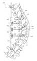
- FIG. 1is a schematic view of a spine deformity correction system in accordance with an embodiment.
- FIG. 2is an enlarged view of a portion of FIG. 1 showing a fixation device in accordance with the illustrated embodiment.
- FIG. 3is a perspective view of a fixation device according to an embodiment.
- FIG. 4is an exploded view of the fixation device shown in FIG. 3 .
- FIG. 5is a perspective view of the transverse member of the fixation device shown in FIG. 3 .
- FIG. 6is a top plan view of a fixation device according to an embodiment, shown implanted in a vertebra.
- FIGS. 7A through 7Cshow plan views of various load-spreading members that can be used with embodiments of the invention.
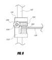
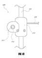
- FIG. 8is an enlarged view of a portion of FIG. 1 showing an adjustment mechanism in accordance with the illustrated embodiment.
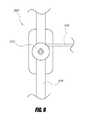
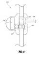
- FIGS. 9 through 13show schematic views of adjustment mechanisms according to various embodiments.
- FIG. 14is a schematic view of a spine deformity correction system in accordance with a further embodiment.
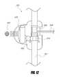
- FIG. 15is an enlarged view of a portion of FIG. 14 showing an adjustment mechanism in accordance with the illustrated embodiment.
- FIG. 16is a process diagram illustrating a method of correcting a spinal deformity, according to a further embodiment.
- the term “vertical”refers to a direction generally in line with, or generally parallel to, a sagittal plane of the body (e.g., generally parallel to the axis of a straightened spine in a standing patient).
- the terms “transverse” and “horizontal”refer to a direction generally in line with, or generally parallel to, a transverse plane of the body (or a transverse plane of a vertebral body), and normal to a sagittal plane of the body (e.g., running from side to side across the spine of a standing patient).
- the systemincludes a rod which can be disposed along a vertical axis to one side of a patient's spine.
- the systemalso includes one or more fixation devices or implants that can be disposed on the other side of the patient's spine, each of which can be inserted into, or otherwise attached to, one or more vertebrae.
- a connectorextends between each implant and the rod. Coupled to the rod is at least one adjustment mechanism which is coupled to the connector. Activation of the adjustment mechanism adjusts the length of the connector, allowing adjustment of the forces applied to an individual vertebra through the connector and its associated implant.
- Embodiments of the inventionthus allow for reversibly adjustable forces to be applied to individual structures, such as individual vertebrae, allowing tensioning and loosening as appropriate.
- Embodiments of the systemcan be implanted surgically and then tightened (or loosened) over an extended period of time if desired, with minimally invasive or noninvasive procedures to provide gradual adjustment.
- Embodimentsalso provide a system for correcting a deformity of the spine which can be used with or without fusion.
- a system 100generally includes a stabilizing rod 102 , one or more implants 104 , one or more adjustment mechanisms 106 , and one or more connectors 108 .
- the rod 102extends generally vertically and is secured to individual vertebrae at locations above and below the curvature to be corrected.
- the illustrated rod 102is attached, according to known methods, to transverse processes on the left side of the spine.
- the rodserves to establish a desired orientation of the spine.
- the rod 102can have an adjustable length, such that its length can adapt to the changing length of the spine as its curvature is straightened.
- the rodcan be a telescoping rod, or the rod can comprise rotatable threaded portions that may be actuated to change overall length of the rod.
- the rod 102can be movable with respect to either or both of the attachment points above and below the curvature of the spine, so as to allow the system 100 to adapt to the lengthening of the spine as the affected vertebrae are translated toward the rod 102 .
- Such a configurationcan advantageously prevent buckling in the rod 102 and/or the spinal column as the curvature of the spine is corrected.
- the implants 104are shown fixed to individual vertebrae within the curved portion of the spine, on the opposite side of the spine from the rod 102 .
- the implants 104include transverse portions 110 which extend across the spine, toward the rod 102 . As better illustrated in FIG. 2 , the transverse portions 110 can pass through the spinous processes of individual vertebrae.
- Each of the transverse portions 110is coupled to one of the connectors 108 .
- the connectors 108extend transversely from the transverse portions 110 of the implants 104 toward the rod 102 , and are coupled to the rod 102 via the adjustment mechanisms 106 .
- the connectors 108are preferably flexible so that they can be used with adjustment mechanisms 106 of a spooling or winding type.
- Suitable flexible connectors 108include monofilament polymer materials, multifilament polymer materials (such as or similar to string or rope), multifilament carbon or ceramic fibers, wire, and multi-stranded cable.
- Stainless steel or titanium wire or ropeare some examples of suitable materials.
- a wide variety of materialscan be used to make the connectors 108 .
- those materialsare preferably biocompatible; indeed, the entire system is preferably made of biocompatible materials.
- FIGS. 3 and 4illustrate in detail an implant 200 configured in accordance with an embodiment.
- the implant 200includes a fixation portion 202 which is configured to be fixed to a portion of a vertebra, such as a pedicle.
- the fixation portion 202can comprise any suitable structure capable of engaging a portion of a vertebra, such as, for example, the illustrated pedicle screw.
- the implant 200also includes a transverse portion 204 coupled to the top end 206 of the fixation portion 202 .
- the transverse portion 204is disposed generally perpendicularly to the fixation portion 202 .
- the fixation portion 202includes at its top end 206 a slot 208 configured to receive a first end 210 of the transverse portion 204 .
- the slot 208is sized to receive a set screw 212 which, when engaged in the slot 208 on top of the first end 210 of the transverse portion 204 , serves to secure the position of the transverse portion 204 relative to the fixation portion 202 .
- an external nut 218can be used to provide additional securement of the transverse portion 204 relative to the fixation portion 202 .
- any suitable couplingcan be used to join the fixation portion 202 and the transverse portion 204 .
- the implantcan also have a unitary construction.
- a connector 214extends from a second end 216 of the transverse portion 204 by an amount sufficient to connect to an adjustment mechanism coupled to a rod, as described herein.
- the connector 214can be attached to the first end 210 of the transverse portion 204 , extending along the length of and past the second end 216 of the transverse portion 204 .
- the connector 214can be attached at any other location along the length of the transverse portion 204 .
- the connector 214may advantageously comprise, for example, a cable or wire, or another material as set forth above, and can be fixed to the transverse portion 204 in any suitable manner, such as by welding or screw fixation.
- FIG. 5illustrates the transverse portion 204 in further detail.
- the transverse portion 204can have a wider, roughly disk-shaped first end 210 so as to engage the receiving slot 208 in the fixation portion 202 .
- the first end 210 of the transverse portion 204 and the top end 206 of the fixation portion 202can have any other suitable cooperating configuration so as to guide and engage one another in an appropriate orientation.
- the transverse portion 204can also have a hollow construction through which the connector 214 can extend.
- an implant 300 in accordance with an embodimentis shown fixed to a single vertebra.
- the implant 300includes a pedicle screw 302 which is fixed to one side of the illustrated vertebra.
- a transverse member 304is advantageously coupled to the head of the pedicle screw 302 and extends through the spinous process of the illustrated vertebra.
- a load-spreading member 306can be provided which encircles, or partially encircles the transverse member 304 at the point of contact between the spinous process and the transverse member 304 , contralateral to the adjustment mechanism and rod (not shown in FIG. 6 ).
- FIGS. 7A through 7Cillustrate various configurations of load-spreading elements according to various embodiments.
- Element 402has an annular configuration configured to spread loads evenly about the point of contact with the spinous process.
- Element 404includes two wings extending from a ring configured to encircle the transverse member.
- Element 406includes tentacles extending from a ring. Configurations such as these can also be used to distribute loads to the lamina, in addition to spreading loads across a larger surface area of the spinous process.
- a load-spreading elementcan have any other configuration suitable for reducing the concentration of force applied to the spinous process by a transverse member extending therethrough, distributing the forces to other portions of the vertebra (for example, to the lamina), and/or for anchoring the transverse member to the spinous process.
- the side of the load-spreading elements that contact bonecan include such features as barbs, fins, pins, or other similar structure to achieve secure attachment of the extensions to the vertebral bone.
- an implant according to an embodimentcan include a transverse member configured to extend between spinous processes of adjacent vertebra.
- the transverse membercan optionally be anchored to one or both of the adjacent spinous processes via a cable, tether, clasp, clamp, screw, hinge, or other suitable means.
- the illustrated embodimentsgenerally show each implant fixed to a single vertebra, embodiments can also include one or more implants configured to be fixed to multiple vertebrae.
- One advantage of multiple-point fixationis the ability to provide not only translational force to the vertebra through the implant, but also rotational force.
- the amount of rotational forcewill depend in part on the distance between the axis of the vertebra and the point of attachment of the connector 108 to the implant 104 .
- This disclosurecontemplates selecting or moving that point of attachment to achieve any desired rotational force, as well as a desired translational force.
- the adjustment mechanism 106may advantageously include a reel 502 , a circumferential gear 504 surrounding the reel 502 , and a vertical gear 506 in contact with the circumferential gear 504 .
- the connector 108is preferably attached to or engaged by the reel 502 . Actuation of the vertical gear 506 via screw head 508 turns the circumferential gear 504 , which turns the reel 502 , thus winding (or unwinding, depending on the direction in which the reel 502 is turned) the connector 108 about the reel 502 .
- Tightening of the reel 502draws the connector 108 in toward the adjustment mechanism 106 , thus pulling the associated implant 104 (not shown in FIG. 8 ) toward the adjustment mechanism.
- the reel 502 and the gears 504 , 506are housed in a clamp 510 .
- the adjustment mechanism 106can be immovably fixed to the rod 102 or can be movable with respect to the rod 102 .
- a movable adjustment mechanism 106provides advantages, for example, as the spine straightens and thus lengthens, so that the adjustment mechanisms 106 can be moved to accommodate the relative movement of the spine in comparison to the rod 102 .
- a movable adjustment mechanism 106also tends to move to the point directly across from the implant 104 , which is the position creating the least amount of tension in the connector 108 and which is also the ideal position for correction.
- FIGS. 9 through 13show examples of adjustment mechanisms according to further embodiments.
- FIG. 9shows an adjustment mechanism 520 comprising only a single reel or gear 522 , around which a connector 524 is wound.
- the gear 522is disposed along on an axis normal to the axis of the rod 526 .
- the gear 522can be directly actuated to tension or loosen the connector 524 .
- FIG. 10shows an adjustment mechanism 530 according to a further embodiment.
- the mechanism 530includes a spring 532 configured to actuate a vertical gear 534 .
- the vertical gear 534contacts a circumferential gear 535 on a reel 536 around which a connector 538 is wound.
- FIG. 11shows an adjustment mechanism 540 according to another embodiment.
- the mechanism 540includes an implantable power supply 542 configured to actuate a motor 544 .
- the motor 544drives a gear 545 on a reel 546 around which a connector 548 is wound.
- the motor 544can be configured to exert gradual forces on the connector 548 (and thus, on an implant to which the connector 548 is attached) without the need for puncturing the patient's skin after the initial implantation of the system.
- the motor 544can be configured to draw in the connector 548 at a predetermined rate (e.g., 3 mm per day).
- the motor 544can be a stepper motor configured to draw in the connector 548 in incremental amounts over time.
- the motor 544can be configured to exert a predetermined amount of tension on the connector 548 .
- Such embodimentscan include one or more sensors, controllers, and related circuitry configured to measure the amount of tension on the connector 548 and adjust the tension applied by the motor 544 accordingly.
- Such embodimentscan be configured to time-average the amount of tension on the connector 548 to allow for variation in tension caused by movement of the patient.
- FIG. 12shows an adjustment mechanism 550 according to a still further embodiment.
- the mechanism 550is coupled to a rod 551 , and includes a first gear 552 configured to turn a second gear 554 .
- the second gear 554contacts a reel 556 , to which a connector 558 is attached.
- FIG. 13illustrates an adjustment mechanism 570 , according to a still further embodiment, coupled to a rod 571 .
- the mechanism 570includes a reel 572 which is actuated by first and second gears 574 , 576 .
- the reel 572is attached to a first connector 578 , which extends generally transversely to an implant on the other side of the spine.
- a second connector 580which extends generally parallel to the rod 571 .
- the second connector 580is connected to a second adjustment mechanism (not shown) and configured so that tightening of the mechanism 570 results in tightening of the second adjustment mechanism as well.
- additional adjustment mechanismscan be coupled to such a system so that a multiple-implant system can be adjusted using a single adjustment point.
- the adjustment mechanism 106is shown to be situated along the rod so that the connector 108 extends generally orthogonal to the rod toward the vertebra on which the implant 104 is located. Although this is a preferred embodiment, it is also contemplated that the adjustment mechanism 106 can be located along the rod 102 so that the angle between the axis of the rod 102 and the connector 108 is other than 90 degrees, e.g., 45 degrees, 60 degrees, 75 degrees, or other non-right-angles. Alternatively, instead of locating the adjustment mechanism(s) 106 along the rod 102 adjacent to (or opposite) the vertebra to be moved, they could be located more remotely, e.g., at an end of the rod 102 .
- the connectorcould still extend from the implant 104 to the rod 102 at a desired angle, e.g., generally orthogonal to the rod 102 , but could then change direction (e.g., by passing over a pulley or through a hole in the rod, not shown) and then extend parallel to or coaxial with the rod, alongside the rod or inside the rod, to the adjustment mechanism(s) 106 .
- the system 600includes a stabilizing rod 602 , one or more implants 604 , one or more adjustment mechanisms 606 , and one or more connectors 608 .
- the implants 604are shown attached to alternate vertebrae. Depending on the particular needs of the application, implants 604 can be fixed to all the vertebrae in a curved portion of a spine, or only certain selected vertebrae.
- FIG. 15shows an enlarged view of one of the adjustment mechanisms 606 .
- the adjustment mechanism 606includes a housing 610 which surrounds a gear/reel mechanism (not visible in FIG. 15 ) as described herein.
- the housing 610includes an opening 612 configured to expose a screw head 614 configured to actuate the gear/reel mechanism. Such a configuration allows for actuation of the gear/reel mechanism 606 while separating the gear/reel mechanism and surrounding body tissues.
- Embodimentsalso include methods of correcting a spinal deformity. Note that the following method description relates to some of the contemplated surgical methods, but it should not be implied that all of the recited method steps are mandatory or that they must be performed in the identical manner specified. Instead, this disclosure is exemplary in nature.
- individual vertebraeare targeted based on a pre-operative plan for correcting an abnormal curvature a patient's spine (such as a scoliotic curvature of a patient's spine).
- Pre-operative planningcan involve review of x-rays or CT scans, as well as physical examination of the patient. Once the targeted vertebrae are identified, implants are surgically fixed to each of the targeted vertebrae.
- Fixing each implantcan involve fixing a first portion of the implant into a pedicle of a vertebra on one side of the patient's spine, inserting a second portion of the implant through a spinous process of the same or different vertebra, and coupling the first and second portions together.
- a vertically extending rodis surgically fixed to the other side of the patient's spine so as to establish a desired orientation of the targeted vertebrae.
- Adjustment mechanisms of the same number as the implantsthat is, the same number as the targeted vertebrae
- Connectorsare positioned between each adjustment member and its corresponding implant. The adjustment mechanisms are then actuated to pull the connectors (and thus the targeted vertebrae) toward the rod.
- the adjustment mechanismsallow for both tightening and loosening of the connectors and, thus, the application of force is reversible.
- the adjustment mechanismscan be tightened or loosened as deemed appropriate by the practitioner and then locked with a locking mechanism such as a set screw.
- applying tension to the connectorsalso exerts rotational forces on the targeted vertebrae, thus derotating the spine as the vertebrae are pulled toward the rod.
- the surgical siteis closed using standard surgical procedures.
- the patientis then examined periodically (for example, every 3 to 6 months) and additional adjustments are made when appropriate.
- post-implantation adjustmentcan be made via a percutaneous puncture allowing the passing of a driver to actuate each adjustment mechanism.
- adjustmentscan be made without the need for puncturing the patient's skin.
- Adjustmentscan be different at each level or adjustment mechanism, depending on the particular anatomy to be adjusted, and different forces or force vectors can be applied to different vertebrae or sections of the spine. Both the curvature and the mal-rotation of the scoliotic spine can thus be corrected over multiple serial adjustments of the adjustment mechanisms.
- the systemmay be explanted after the deformity of the spine is eliminated or reduced to a clinically acceptable position.
- FIG. 16A method of correcting a spinal deformity is illustrated in FIG. 16 .
- an implantis affixed to a first side of a vertebra.
- a rodis positioned on a second side of the vertebra so that the rod extends between the adjustment member and the implant.
- an adjustment memberis provided which is coupled to the rod.
- a force directing memberis positioned so that it extends between the adjustment member and the implant.
- a forceis applied to the force directing member with the adjustment member, thereby moving the vertebra toward the rod.
- Embodiments of the inventioncan be used with or without fusion of vertebrae.
- some vertebrae of the spinemay be fused according to known procedures using screws, hooks and/or rod systems following initial or subsequent adjustments or after explantation.
- some or all vertebraemay be left non-fused.
- one or more adjustment mechanisms according to embodimentscan be used to adjust tension on anatomical structures other than spinal structures.
- embodiments of the inventioncan be configured and used to adjust the tension, laxity, or distance between an anchor structure and an anatomical structure.
- Examples of such embodimentsinclude providing an adjustable ligament between the femur and tibia of the leg, for example to correct a torn cruciate ligament; providing an adjustable sling between the pelvis or pubis and the bladder or urethra for the treatment of urinary incontinence; providing an adjustable attachment between a bone (such as the pelvis) and the uterus for the treatment of uterine prolapse; providing an adjustable attachment between the mandible or hyoid bone and the tongue or other upper airway structure for the treatment of snoring or obstructive sleep apnea; and providing an adjustable lifting mechanism between a cranial bone and soft tissue of the face to enable an adjustable face lift or eye lift.
Landscapes
- Health & Medical Sciences (AREA)
- Orthopedic Medicine & Surgery (AREA)
- Life Sciences & Earth Sciences (AREA)
- Neurology (AREA)
- Surgery (AREA)
- Heart & Thoracic Surgery (AREA)
- Engineering & Computer Science (AREA)
- Biomedical Technology (AREA)
- Nuclear Medicine, Radiotherapy & Molecular Imaging (AREA)
- Medical Informatics (AREA)
- Molecular Biology (AREA)
- Animal Behavior & Ethology (AREA)
- General Health & Medical Sciences (AREA)
- Public Health (AREA)
- Veterinary Medicine (AREA)
- Prostheses (AREA)
- Surgical Instruments (AREA)
Abstract
Description
Claims (37)
Priority Applications (4)
| Application Number | Priority Date | Filing Date | Title |
|---|---|---|---|
| US14/628,573US9848917B2 (en) | 2007-06-06 | 2015-02-23 | Medical device and method to correct deformity |
| US15/817,750US10426523B2 (en) | 2007-06-06 | 2017-11-20 | Medical device and method to correct deformity |
| US16/565,994US11246628B2 (en) | 2007-06-06 | 2019-09-10 | Medical device and method to correct deformity |
| US17/668,955US12262922B2 (en) | 2007-06-06 | 2022-02-10 | Medical device and method to correct deformity |
Applications Claiming Priority (4)
| Application Number | Priority Date | Filing Date | Title |
|---|---|---|---|
| US93332607P | 2007-06-06 | 2007-06-06 | |
| US12/134,058US8162979B2 (en) | 2007-06-06 | 2008-06-05 | Medical device and method to correct deformity |
| US13/446,950US20120203282A1 (en) | 2007-06-06 | 2012-04-13 | Medical device and method to correct deformity |
| US14/628,573US9848917B2 (en) | 2007-06-06 | 2015-02-23 | Medical device and method to correct deformity |
Related Parent Applications (1)
| Application Number | Title | Priority Date | Filing Date |
|---|---|---|---|
| US13/446,950ContinuationUS20120203282A1 (en) | 2007-06-06 | 2012-04-13 | Medical device and method to correct deformity |
Related Child Applications (1)
| Application Number | Title | Priority Date | Filing Date |
|---|---|---|---|
| US15/817,750ContinuationUS10426523B2 (en) | 2007-06-06 | 2017-11-20 | Medical device and method to correct deformity |
Publications (2)
| Publication Number | Publication Date |
|---|---|
| US20160008036A1 US20160008036A1 (en) | 2016-01-14 |
| US9848917B2true US9848917B2 (en) | 2017-12-26 |
Family
ID=40130136
Family Applications (6)
| Application Number | Title | Priority Date | Filing Date |
|---|---|---|---|
| US12/134,058Expired - Fee RelatedUS8162979B2 (en) | 2007-06-06 | 2008-06-05 | Medical device and method to correct deformity |
| US13/446,950AbandonedUS20120203282A1 (en) | 2007-06-06 | 2012-04-13 | Medical device and method to correct deformity |
| US14/628,573Expired - Fee RelatedUS9848917B2 (en) | 2007-06-06 | 2015-02-23 | Medical device and method to correct deformity |
| US15/817,750Expired - Fee RelatedUS10426523B2 (en) | 2007-06-06 | 2017-11-20 | Medical device and method to correct deformity |
| US16/565,994Active2028-10-19US11246628B2 (en) | 2007-06-06 | 2019-09-10 | Medical device and method to correct deformity |
| US17/668,955Active2029-07-06US12262922B2 (en) | 2007-06-06 | 2022-02-10 | Medical device and method to correct deformity |
Family Applications Before (2)
| Application Number | Title | Priority Date | Filing Date |
|---|---|---|---|
| US12/134,058Expired - Fee RelatedUS8162979B2 (en) | 2007-06-06 | 2008-06-05 | Medical device and method to correct deformity |
| US13/446,950AbandonedUS20120203282A1 (en) | 2007-06-06 | 2012-04-13 | Medical device and method to correct deformity |
Family Applications After (3)
| Application Number | Title | Priority Date | Filing Date |
|---|---|---|---|
| US15/817,750Expired - Fee RelatedUS10426523B2 (en) | 2007-06-06 | 2017-11-20 | Medical device and method to correct deformity |
| US16/565,994Active2028-10-19US11246628B2 (en) | 2007-06-06 | 2019-09-10 | Medical device and method to correct deformity |
| US17/668,955Active2029-07-06US12262922B2 (en) | 2007-06-06 | 2022-02-10 | Medical device and method to correct deformity |
Country Status (6)
| Country | Link |
|---|---|
| US (6) | US8162979B2 (en) |
| EP (1) | EP2155086B1 (en) |
| JP (1) | JP2010528779A (en) |
| AU (1) | AU2008262019B2 (en) |
| CA (1) | CA2689965A1 (en) |
| WO (1) | WO2008154313A1 (en) |
Cited By (1)
| Publication number | Priority date | Publication date | Assignee | Title |
|---|---|---|---|---|
| US20180070991A1 (en)* | 2007-06-06 | 2018-03-15 | K2M, Inc. | Medical device and method to correct deformity |
Families Citing this family (88)
| Publication number | Priority date | Publication date | Assignee | Title |
|---|---|---|---|---|
| US7955357B2 (en) | 2004-07-02 | 2011-06-07 | Ellipse Technologies, Inc. | Expandable rod system to treat scoliosis and method of using the same |
| US8114158B2 (en)* | 2004-08-03 | 2012-02-14 | Kspine, Inc. | Facet device and method |
| US7776072B2 (en) | 2004-12-30 | 2010-08-17 | Barry Mark A | System and method for aligning vertebrae in the amelioration of aberrant spinal column deviation conditions |
| US9339301B2 (en) | 2004-12-30 | 2016-05-17 | Mark A. Barry | System and method for aligning vertebrae in the amelioration of aberrant spinal column deviation conditions |
| US7862502B2 (en) | 2006-10-20 | 2011-01-04 | Ellipse Technologies, Inc. | Method and apparatus for adjusting a gastrointestinal restriction device |
| US20090112262A1 (en) | 2007-10-30 | 2009-04-30 | Scott Pool | Skeletal manipulation system |
| WO2009120764A2 (en) | 2008-03-25 | 2009-10-01 | Ellipse Technologies, Inc. | Systems and methods for adjusting an annuloplasty ring with an integrated magnetic drive |
| US11202707B2 (en) | 2008-03-25 | 2021-12-21 | Nuvasive Specialized Orthopedics, Inc. | Adjustable implant system |
| US11241257B2 (en) | 2008-10-13 | 2022-02-08 | Nuvasive Specialized Orthopedics, Inc. | Spinal distraction system |
| US8308775B2 (en)* | 2008-10-14 | 2012-11-13 | Medicrea International | Method for rotating a vertebra or vertebrae |
| US8382756B2 (en) | 2008-11-10 | 2013-02-26 | Ellipse Technologies, Inc. | External adjustment device for distraction device |
| US8828058B2 (en) | 2008-11-11 | 2014-09-09 | Kspine, Inc. | Growth directed vertebral fixation system with distractible connector(s) and apical control |
| US8043338B2 (en) | 2008-12-03 | 2011-10-25 | Zimmer Spine, Inc. | Adjustable assembly for correcting spinal abnormalities |
| US8197490B2 (en) | 2009-02-23 | 2012-06-12 | Ellipse Technologies, Inc. | Non-invasive adjustable distraction system |
| AU2015230721B2 (en)* | 2009-03-26 | 2017-11-16 | K2M, Inc. | Semi - constrained anchoring system for correcting a spinal deformity |
| US8357182B2 (en)* | 2009-03-26 | 2013-01-22 | Kspine, Inc. | Alignment system with longitudinal support features |
| US9622792B2 (en) | 2009-04-29 | 2017-04-18 | Nuvasive Specialized Orthopedics, Inc. | Interspinous process device and method |
| US20100318129A1 (en)* | 2009-06-16 | 2010-12-16 | Kspine, Inc. | Deformity alignment system with reactive force balancing |
| US8876867B2 (en) | 2009-06-24 | 2014-11-04 | Zimmer Spine, Inc. | Spinal correction tensioning system |
| JP5751642B2 (en) | 2009-09-04 | 2015-07-22 | エリプス テクノロジーズ, インク.Ellipse Technologies, Inc. | Bone growth apparatus and method |
| US9168071B2 (en) | 2009-09-15 | 2015-10-27 | K2M, Inc. | Growth modulation system |
| US8328849B2 (en)* | 2009-12-01 | 2012-12-11 | Zimmer Gmbh | Cord for vertebral stabilization system |
| US8641723B2 (en) | 2010-06-03 | 2014-02-04 | Orthonex LLC | Skeletal adjustment device |
| US9248043B2 (en) | 2010-06-30 | 2016-02-02 | Ellipse Technologies, Inc. | External adjustment device for distraction device |
| WO2012021378A2 (en)* | 2010-08-09 | 2012-02-16 | Ellipse Technologies, Inc. | Maintenance feature in magnetic implant |
| US8282671B2 (en) | 2010-10-25 | 2012-10-09 | Orthonex | Smart device for non-invasive skeletal adjustment |
| US8721566B2 (en)* | 2010-11-12 | 2014-05-13 | Robert A. Connor | Spinal motion measurement device |
| US9211145B2 (en)* | 2010-11-29 | 2015-12-15 | Javier Pereiro de Lamo | Method and system for the treatment of spinal deformities |
| US20140107707A1 (en)* | 2011-02-10 | 2014-04-17 | Robert A. Rovner | Table anchored scoliosis de-rotation system and method |
| WO2012112396A2 (en) | 2011-02-14 | 2012-08-23 | Ellipse Technologies, Inc. | Device and method for treating fractured bones |
| JP6158176B2 (en)* | 2011-06-03 | 2017-07-05 | ケイツーエム インコーポレイテッドK2M,Inc. | Spine correction system |
| US10743794B2 (en) | 2011-10-04 | 2020-08-18 | Nuvasive Specialized Orthopedics, Inc. | Devices and methods for non-invasive implant length sensing |
| US10016220B2 (en) | 2011-11-01 | 2018-07-10 | Nuvasive Specialized Orthopedics, Inc. | Adjustable magnetic devices and methods of using same |
| US8920472B2 (en)* | 2011-11-16 | 2014-12-30 | Kspine, Inc. | Spinal correction and secondary stabilization |
| US9451987B2 (en) | 2011-11-16 | 2016-09-27 | K2M, Inc. | System and method for spinal correction |
| US9468469B2 (en) | 2011-11-16 | 2016-10-18 | K2M, Inc. | Transverse coupler adjuster spinal correction systems and methods |
| US9468468B2 (en)* | 2011-11-16 | 2016-10-18 | K2M, Inc. | Transverse connector for spinal stabilization system |
| WO2014172632A2 (en)* | 2011-11-16 | 2014-10-23 | Kspine, Inc. | Spinal correction and secondary stabilization |
| US20130123853A1 (en)* | 2011-11-16 | 2013-05-16 | Kspine, Inc. | Spinal correction and secondary stabilization |
| US9949761B2 (en) | 2011-12-12 | 2018-04-24 | Children's Hospital Medical Center Of Akron | Noninvasive device for adjusting fastener |
| US9078711B2 (en) | 2012-06-06 | 2015-07-14 | Ellipse Technologies, Inc. | Devices and methods for detection of slippage of magnetic coupling in implantable medical devices |
| US20130338714A1 (en) | 2012-06-15 | 2013-12-19 | Arvin Chang | Magnetic implants with improved anatomical compatibility |
| US10327818B2 (en)* | 2012-06-18 | 2019-06-25 | Bruce Francis Hodgson | Method and apparatus for the treatment of scoliosis |
| US8764803B2 (en)* | 2012-10-04 | 2014-07-01 | Loubert S. Suddaby | Apparatus and method for aligning a spine |
| US10022153B2 (en) | 2012-10-04 | 2018-07-17 | Loubert S. Suddaby | Percutaneous method for aligning a spine using deployable bone anchors |
| US9968379B2 (en)* | 2012-10-04 | 2018-05-15 | Loubert S. Suddaby | Subcutaneous implantable device for gradually aligning a spine and subcutaneous implantable device for gradually lengthening a bone |
| US9480519B2 (en) | 2012-10-04 | 2016-11-01 | Loubert S. Suddaby | Apparatus for aligning a spine using deployable bone anchors and method for the same |
| US9044281B2 (en) | 2012-10-18 | 2015-06-02 | Ellipse Technologies, Inc. | Intramedullary implants for replacing lost bone |
| EP2911616B1 (en) | 2012-10-29 | 2020-10-07 | NuVasive Specialized Orthopedics, Inc. | Adjustable devices for treating arthritis of the knee |
| GB201220042D0 (en)* | 2012-11-07 | 2012-12-19 | Murray David W | Adjusting spinal curvature |
| WO2014127464A1 (en)* | 2013-02-25 | 2014-08-28 | Polyvalor, Limited Partnership | Cyclic controlled dynamic device for the correction of spinal deformities |
| US9179938B2 (en) | 2013-03-08 | 2015-11-10 | Ellipse Technologies, Inc. | Distraction devices and method of assembling the same |
| WO2014145470A2 (en)* | 2013-03-15 | 2014-09-18 | Agarwal Anand K | Spinal rods formed from polymer and hybrid materials and growth rod distraction system including same |
| US10226242B2 (en) | 2013-07-31 | 2019-03-12 | Nuvasive Specialized Orthopedics, Inc. | Noninvasively adjustable suture anchors |
| US9801734B1 (en) | 2013-08-09 | 2017-10-31 | Nuvasive, Inc. | Lordotic expandable interbody implant |
| US9468471B2 (en) | 2013-09-17 | 2016-10-18 | K2M, Inc. | Transverse coupler adjuster spinal correction systems and methods |
| US10751094B2 (en)* | 2013-10-10 | 2020-08-25 | Nuvasive Specialized Orthopedics, Inc. | Adjustable spinal implant |
| CN106456215B (en) | 2014-04-28 | 2020-04-10 | 诺威适骨科专科公司 | External adjustment device for adjusting a medical implant |
| KR102588501B1 (en) | 2014-10-23 | 2023-10-11 | 누베이시브 스페셜라이즈드 오소페딕스, 인크. | Remotely adjustable interactive bone reshaping implant |
| ES2908064T3 (en) | 2014-12-26 | 2022-04-27 | Nuvasive Specialized Orthopedics Inc | distraction systems |
| US10238427B2 (en) | 2015-02-19 | 2019-03-26 | Nuvasive Specialized Orthopedics, Inc. | Systems and methods for vertebral adjustment |
| US9968378B1 (en)* | 2015-07-22 | 2018-05-15 | University Of South Florida | Adaptation sphere saddle |
| US11071568B2 (en)* | 2015-10-05 | 2021-07-27 | Globus Medical, Inc. | Growing rod for treating spinal deformities and method for using same |
| US11259844B2 (en)* | 2015-10-05 | 2022-03-01 | Globus Medical Inc. | Growing rod for treating spinal deformities and method for using same |
| BR112018007347A2 (en) | 2015-10-16 | 2018-10-23 | Nuvasive Specialized Orthopedics, Inc. | adjustable devices for the treatment of knee arthritis |
| CN108601611B (en) | 2015-12-10 | 2021-11-02 | 诺威适骨科专科公司 | External adjustment device for stretcher |
| US10216943B2 (en)* | 2015-12-17 | 2019-02-26 | International Business Machines Corporation | Dynamic security questions in electronic account management |
| BR112018015504A2 (en) | 2016-01-28 | 2018-12-18 | Nuvasive Specialized Orthopedics, Inc. | bone transport systems |
| WO2017139548A1 (en) | 2016-02-10 | 2017-08-17 | Nuvasive Specialized Orthopedics, Inc. | Systems and methods for controlling multiple surgical variables |
| EP3413820B1 (en) | 2016-02-12 | 2024-04-10 | Nuvasive, Inc. | Post-operatively adjustable spinal fixation devices |
| CN109152596B (en)* | 2016-05-19 | 2022-07-08 | 奥图斯外科手术股份有限公司 | Spinal curvature adjustment system |
| US12262917B2 (en) | 2016-05-19 | 2025-04-01 | Auctus Surgical, Inc. | Spinal curvature modulation systems and methods |
| WO2018102101A2 (en) | 2016-11-09 | 2018-06-07 | Children's Hospital Medical Center Of Akron | Distraction osteogenesis system |
| US10188428B2 (en)* | 2017-05-15 | 2019-01-29 | Loubert S. Suddaby | Subcutaneous implantable device for gradually aligning a spine |
| US11304730B2 (en) | 2017-12-22 | 2022-04-19 | Orthopediatrics Corp. | Tethered restraint of vertebral bodies |
| US11317949B2 (en) | 2018-04-25 | 2022-05-03 | Loubert S. Suddaby | Segmented alignment rod assembly |
| US11580268B2 (en) | 2018-04-25 | 2023-02-14 | Loubert S. Suddaby | Method of creating a customized segmented alignment rod for alignment of a spine |
| US11759210B1 (en)* | 2018-07-04 | 2023-09-19 | Axsonus LLC | Method and system for distraction neurogenesis |
| MX2021002819A (en)* | 2018-09-10 | 2021-08-11 | Amb Orthopedics Inc | Systems and methods for adjusting a growing rod. |
| JP2022519380A (en) | 2019-02-07 | 2022-03-23 | ニューベイシブ スペシャライズド オーソペディックス,インコーポレイテッド | Ultrasonic communication in medical devices |
| US11589901B2 (en) | 2019-02-08 | 2023-02-28 | Nuvasive Specialized Orthopedics, Inc. | External adjustment device |
| WO2021173511A1 (en)* | 2020-02-27 | 2021-09-02 | Suddaby Loubert S | Segmented alignment rod assembly and method of making the same |
| US12213708B2 (en) | 2020-09-08 | 2025-02-04 | Nuvasive Specialized Orthopedics, Inc. | Remote control module for adjustable implants |
| CN112402001B (en)* | 2020-09-11 | 2022-03-08 | 南昌大学第二附属医院 | Universal centrum resetting device for orthopedic spine operation |
| US20220265326A1 (en) | 2021-02-23 | 2022-08-25 | Nuvasive Specialized Orthopedics, Inc. | Adjustable implant, system and methods |
| US11737787B1 (en) | 2021-05-27 | 2023-08-29 | Nuvasive, Inc. | Bone elongating devices and methods of use |
| EP4380480A1 (en) | 2021-08-03 | 2024-06-12 | NuVasive Specialized Orthopedics, Inc. | Adjustable implant |
| US12137941B2 (en)* | 2021-12-23 | 2024-11-12 | Orthofix S.R.L. | Orthopedic cable bone transport device and bone transport system comprising said device |
Citations (317)
| Publication number | Priority date | Publication date | Assignee | Title |
|---|---|---|---|---|
| US2774350A (en) | 1952-09-08 | 1956-12-18 | Jr Carl S Cleveland | Spinal clamp or splint |
| US3242922A (en) | 1963-06-25 | 1966-03-29 | Charles B Thomas | Internal spinal fixation means |
| US3352226A (en) | 1965-03-15 | 1967-11-14 | Silas E Nelsen | Infusion package |
| US3648691A (en) | 1970-02-24 | 1972-03-14 | Univ Colorado State Res Found | Method of applying vertebral appliance |
| US3693616A (en) | 1970-06-26 | 1972-09-26 | Robert Roaf | Device for correcting scoliotic curves |
| US3865105A (en) | 1973-05-16 | 1975-02-11 | Lode S Instr N V | Device for exerting forces on and fixing the spinal column of a human body |
| US4024588A (en) | 1974-10-04 | 1977-05-24 | Allo Pro A.G. | Artificial joints with magnetic attraction or repulsion |
| US4078559A (en)* | 1975-05-30 | 1978-03-14 | Erkki Einari Nissinen | Straightening and supporting device for the spinal column in the surgical treatment of scoliotic diseases |
| DE2845647A1 (en) | 1978-10-20 | 1980-05-08 | Messerschmitt Boelkow Blohm | Implanted surgical device for correcting spinal curvature - has correction rod rotated by motor to gradually shorten wire attached to spine |
| US4269178A (en) | 1979-06-04 | 1981-05-26 | Keene James S | Hook assembly for engaging a spinal column |
| US4274401A (en) | 1978-12-08 | 1981-06-23 | Miskew Don B W | Apparatus for correcting spinal deformities and method for using |
| SU888968A1 (en) | 1979-01-11 | 1981-12-15 | Новосибирский научно-исследовательский институт травматологии и ортопедии | Apparatus for correcting vertebral column |
| US4355645A (en)* | 1978-10-18 | 1982-10-26 | Kabushiki Kaisha Morita Seisakusho | Device for displaying masticatory muscle activities |
| US4361141A (en) | 1979-07-27 | 1982-11-30 | Zimmer Usa, Inc. | Scoliosis transverse traction assembly |
| US4369769A (en) | 1980-06-13 | 1983-01-25 | Edwards Charles C | Spinal fixation device and method |
| US4404967A (en) | 1982-01-18 | 1983-09-20 | Wyzsza Szkola Inzynierska Im. Jurija Gagarina | Surgical strut for treatment of the back-bone |
| US4411259A (en) | 1980-02-04 | 1983-10-25 | Drummond Denis S | Apparatus for engaging a hook assembly to a spinal column |
| US4411545A (en) | 1981-03-06 | 1983-10-25 | Skf Compagnie D'applications Mecaniques - Adr | Swivel joint |
| US4448191A (en) | 1981-07-07 | 1984-05-15 | Rodnyansky Lazar I | Implantable correctant of a spinal curvature and a method for treatment of a spinal curvature |
| US4505268A (en) | 1983-02-17 | 1985-03-19 | Vicente Sgandurra | Scoliosis frame |
| US4554914A (en) | 1983-10-04 | 1985-11-26 | Kapp John P | Prosthetic vertebral body |
| US4573454A (en) | 1984-05-17 | 1986-03-04 | Hoffman Gregory A | Spinal fixation apparatus |
| US4604995A (en) | 1984-03-30 | 1986-08-12 | Stephens David C | Spinal stabilizer |
| US4611582A (en) | 1983-12-27 | 1986-09-16 | Wisconsin Alumni Research Foundation | Vertebral clamp |
| US4611581A (en) | 1983-12-16 | 1986-09-16 | Acromed Corporation | Apparatus for straightening spinal columns |
| US4648388A (en) | 1985-11-01 | 1987-03-10 | Acromed Corporation | Apparatus and method for maintaining vertebrae in a desired relationship |
| US4653481A (en) | 1985-07-24 | 1987-03-31 | Howland Robert S | Advanced spine fixation system and method |
| US4697582A (en) | 1983-10-28 | 1987-10-06 | Peze William | Appliance for correcting rachidial deformities |
| US4738251A (en) | 1987-02-20 | 1988-04-19 | Codespi, Corporation | Correcting device for spine pathology |
| US4773402A (en) | 1985-09-13 | 1988-09-27 | Isola Implants, Inc. | Dorsal transacral surgical implant |
| US4805602A (en) | 1986-11-03 | 1989-02-21 | Danninger Medical Technology | Transpedicular screw and rod system |
| US4815453A (en) | 1983-05-04 | 1989-03-28 | Societe De Fabrication De Materiel Orthopedique (Sofamor) | Device for supporting the rachis |
| US4827918A (en) | 1985-08-15 | 1989-05-09 | Sven Olerud | Fixing instrument for use in spinal surgery |
| US4854311A (en) | 1986-01-09 | 1989-08-08 | Acro Med Corporation | Bone screw |
| US4936848A (en) | 1989-09-22 | 1990-06-26 | Bagby George W | Implant for vertebrae |
| US5000166A (en) | 1988-04-27 | 1991-03-19 | Sulzer Brothers Limited | Implant kit for stabilizing regions of a spine |
| EP0418387A1 (en) | 1989-02-21 | 1991-03-27 | Vsesojuzny Kurgansky Nauchny Tsentr "Vosstanovitelnaya Travmatologia I Ortopedia" | Device for treatment of curvature of and damage to the spine |
| US5005562A (en) | 1988-06-24 | 1991-04-09 | Societe De Fabrication De Material Orthopedique | Implant for spinal osteosynthesis device, in particular in traumatology |
| US5011484A (en) | 1987-11-16 | 1991-04-30 | Breard Francis H | Surgical implant for restricting the relative movement of vertebrae |
| US5030220A (en) | 1990-03-29 | 1991-07-09 | Advanced Spine Fixation Systems Incorporated | Spine fixation system |
| US5042982A (en) | 1987-07-08 | 1991-08-27 | Harms Juergen | Positioning device |
| US5084049A (en) | 1989-02-08 | 1992-01-28 | Acromed Corporation | Transverse connector for spinal column corrective devices |
| US5092866A (en) | 1989-02-03 | 1992-03-03 | Breard Francis H | Flexible inter-vertebral stabilizer as well as process and apparatus for determining or verifying its tension before installation on the spinal column |
| US5092867A (en) | 1988-07-13 | 1992-03-03 | Harms Juergen | Correction and supporting apparatus, in particular for the spinal column |
| US5127912A (en) | 1990-10-05 | 1992-07-07 | R. Charles Ray | Sacral implant system |
| US5129900A (en) | 1990-07-24 | 1992-07-14 | Acromed Corporation | Spinal column retaining method and apparatus |
| US5133716A (en) | 1990-11-07 | 1992-07-28 | Codespi Corporation | Device for correction of spinal deformities |
| US5147363A (en) | 1989-12-21 | 1992-09-15 | Haerle Anton | Screw for use in osteosynthesis |
| US5176679A (en) | 1991-09-23 | 1993-01-05 | Lin Chih I | Vertebral locking and retrieving system |
| US5176680A (en) | 1990-02-08 | 1993-01-05 | Vignaud Jean Louis | Device for the adjustable fixing of spinal osteosynthesis rods |
| US5181917A (en) | 1990-06-19 | 1993-01-26 | Chaim Rogozinski | System and method for instrumentation of the spine in the treatment of spinal deformities |
| US5190543A (en) | 1990-11-26 | 1993-03-02 | Synthes (U.S.A.) | Anchoring device |
| US5207678A (en) | 1989-07-20 | 1993-05-04 | Prufer | Pedicle screw and receiver member therefore |
| US5209752A (en) | 1991-12-04 | 1993-05-11 | Danek Medical, Inc. | Lateral offset connector for spinal implant system |
| US5219349A (en) | 1991-02-15 | 1993-06-15 | Howmedica, Inc. | Spinal fixator reduction frame |
| US5242443A (en) | 1991-08-15 | 1993-09-07 | Smith & Nephew Dyonics, Inc. | Percutaneous fixation of vertebrae |
| US5254118A (en) | 1991-12-04 | 1993-10-19 | Srdjian Mirkovic | Three dimensional spine fixation system |
| US5257994A (en) | 1991-09-23 | 1993-11-02 | Lin Chih I | Vertebral locking and retrieving system |
| US5259398A (en) | 1989-10-26 | 1993-11-09 | Giuseppe Vrespa | Method for fixing prosthesis to bones |
| US5282862A (en) | 1991-12-03 | 1994-02-01 | Artifex Ltd. | Spinal implant system and a method for installing the implant onto a vertebral column |
| US5306275A (en) | 1992-12-31 | 1994-04-26 | Bryan Donald W | Lumbar spine fixation apparatus and method |
| FR2697744A1 (en) | 1992-11-10 | 1994-05-13 | Fabrication Mat Orthopedique S | Spinal osteosynthesis instrumentation by the anterior route. |
| US5312410A (en) | 1992-12-07 | 1994-05-17 | Danek Medical, Inc. | Surgical cable tensioner |
| US5330474A (en) | 1991-09-23 | 1994-07-19 | Lin Chih I | Vertebral locking and retrieving system |
| US5352226A (en) | 1993-02-08 | 1994-10-04 | Lin Chih I | Side locking system rotatable in all directions for use in spinal surgery |
| US5366455A (en) | 1988-11-04 | 1994-11-22 | Surgicraft Limited | Pedicle engaging means |
| US5368594A (en) | 1991-09-30 | 1994-11-29 | Fixano S.A. | Vertebral osteosynthesis device |
| US5380323A (en) | 1993-06-16 | 1995-01-10 | Advanced Spine Fixation Systems, Inc. | Clamps for spinal fixation systems |
| US5380325A (en) | 1992-11-06 | 1995-01-10 | Biomat | Osteosynthesis device for spinal consolidation |
| US5382248A (en) | 1992-09-10 | 1995-01-17 | H. D. Medical, Inc. | System and method for stabilizing bone segments |
| US5387213A (en) | 1991-02-05 | 1995-02-07 | Safir S.A.R.L. | Osseous surgical implant particularly for an intervertebral stabilizer |
| US5387212A (en) | 1993-01-26 | 1995-02-07 | Yuan; Hansen A. | Vertebral locking and retrieving system with central locking rod |
| US5391168A (en) | 1992-04-01 | 1995-02-21 | Acromed B.V. | Device for correcting the shape of the human spinal column and/or for fixing the human spinal column |
| US5397363A (en) | 1992-08-11 | 1995-03-14 | Gelbard; Steven D. | Spinal stabilization implant system |
| US5413576A (en)* | 1993-02-10 | 1995-05-09 | Rivard; Charles-Hilaire | Apparatus for treating spinal disorder |
| US5436542A (en)* | 1994-01-28 | 1995-07-25 | Surgix, Inc. | Telescopic camera mount with remotely controlled positioning |
| US5437669A (en) | 1993-08-12 | 1995-08-01 | Amei Technologies Inc. | Spinal fixation systems with bifurcated connectors |
| US5437671A (en) | 1992-03-10 | 1995-08-01 | Zimmer, Inc. | Perpendicular rod connector for spinal fixation device |
| US5456722A (en) | 1993-01-06 | 1995-10-10 | Smith & Nephew Richards Inc. | Load bearing polymeric cable |
| US5470333A (en) | 1993-03-11 | 1995-11-28 | Danek Medical, Inc. | System for stabilizing the cervical and the lumbar region of the spine |
| US5480440A (en) | 1991-08-15 | 1996-01-02 | Smith & Nephew Richards, Inc. | Open surgical technique for vertebral fixation with subcutaneous fixators positioned between the skin and the lumbar fascia of a patient |
| US5486174A (en) | 1993-02-24 | 1996-01-23 | Soprane S.A. | Fastener for the osteosynthesis of the spinal column |
| US5487744A (en) | 1993-04-08 | 1996-01-30 | Advanced Spine Fixation Systems, Inc. | Closed connector for spinal fixation systems |
| US5490851A (en) | 1994-08-02 | 1996-02-13 | Nenov; Nikolay N. | Method and apparatus for treatment of idiopathic scoliosis |
| US5496318A (en) | 1993-01-08 | 1996-03-05 | Advanced Spine Fixation Systems, Inc. | Interspinous segmental spine fixation device |
| US5498262A (en) | 1992-12-31 | 1996-03-12 | Bryan; Donald W. | Spinal fixation apparatus and method |
| US5501684A (en) | 1992-06-25 | 1996-03-26 | Synthes (U.S.A.) | Osteosynthetic fixation device |
| US5520688A (en) | 1994-07-20 | 1996-05-28 | Lin; Chih-I | Vertebral auxiliary fixation device |
| US5540689A (en) | 1990-05-22 | 1996-07-30 | Sanders; Albert E. | Apparatus for securing a rod adjacent to a bone |
| US5544993A (en) | 1993-12-13 | 1996-08-13 | H+E,Uml A+Ee Rle; Anton | Threaded fastener |
| US5549679A (en) | 1994-05-20 | 1996-08-27 | Kuslich; Stephen D. | Expandable fabric implant for stabilizing the spinal motion segment |
| US5562662A (en) | 1993-01-04 | 1996-10-08 | Danek Medical Inc. | Spinal fixation system and method |
| US5562660A (en) | 1993-02-09 | 1996-10-08 | Plus Endoprothetik Ag | Apparatus for stiffening and/or correcting the vertebral column |
| US5569246A (en) | 1993-12-28 | 1996-10-29 | Asahi Kogaku Kogyo Kabushiki Kaisha | Fixing instrument for spinal fusion members |
| US5571191A (en) | 1995-03-16 | 1996-11-05 | Fitz; William R. | Artificial facet joint |
| US5584626A (en) | 1995-06-15 | 1996-12-17 | Excelsior Development Inc. | Torque-limiting fastening element |
| US5586983A (en) | 1990-05-22 | 1996-12-24 | Sanders; Albert E. | Bone clamp of shape memory material |
| US5591165A (en) | 1992-11-09 | 1997-01-07 | Sofamor, S.N.C. | Apparatus and method for spinal fixation and correction of spinal deformities |
| FR2736535A1 (en) | 1995-07-10 | 1997-01-17 | Martin Jean Jacques | Spinal osteosynthesis device to immobilise portion of spine e.g. in case of pathological degeneration between vertebrae |
| US5611800A (en) | 1994-02-15 | 1997-03-18 | Alphatec Manufacturing, Inc. | Spinal fixation system |
| US5643259A (en) | 1994-03-31 | 1997-07-01 | Ricardo C. Sasso | Spine fixation instrumentation |
| US5645599A (en) | 1994-07-26 | 1997-07-08 | Fixano | Interspinal vertebral implant |
| US5649926A (en) | 1994-07-14 | 1997-07-22 | Advanced Spine Fixation Systems, Inc. | Spinal segmental reduction derotational fixation system |
| US5658284A (en) | 1994-06-30 | 1997-08-19 | Allo Pro Ag | Connection member for the connection of a resilient rod with a bone screw which can be anchored in a vertebra |
| US5672175A (en) | 1993-08-27 | 1997-09-30 | Martin; Jean Raymond | Dynamic implanted spinal orthosis and operative procedure for fitting |
| US5676703A (en) | 1994-05-11 | 1997-10-14 | Gelbard; Steven D. | Spinal stabilization implant system |
| US5702395A (en) | 1992-11-10 | 1997-12-30 | Sofamor S.N.C. | Spine osteosynthesis instrumentation for an anterior approach |
| US5702399A (en) | 1996-05-16 | 1997-12-30 | Pioneer Laboratories, Inc. | Surgical cable screw connector |
| US5702452A (en) | 1995-01-23 | 1997-12-30 | Sofamor S.N.C. | Spinal osteosynthesis device with median hook and vertebral anchoring support |
| US5704936A (en) | 1992-04-10 | 1998-01-06 | Eurosurgical | Spinal osteosynthesis device |
| US5713898A (en) | 1993-05-18 | 1998-02-03 | Schafer Micomed Gmbh | Orthopedic surgical holding device |
| US5725582A (en) | 1992-08-19 | 1998-03-10 | Surgicraft Limited | Surgical implants |
| US5728097A (en) | 1992-03-17 | 1998-03-17 | Sdgi Holding, Inc. | Method for subcutaneous suprafascial internal fixation |
| US5733284A (en) | 1993-08-27 | 1998-03-31 | Paulette Fairant | Device for anchoring spinal instrumentation on a vertebra |
| US5735852A (en) | 1995-05-22 | 1998-04-07 | Synthes (U.S.A.) | Clamp jaw for a spinal affixation device |
| US5782831A (en) | 1996-11-06 | 1998-07-21 | Sdgi Holdings, Inc. | Method an device for spinal deformity reduction using a cable and a cable tensioning system |
| US5797910A (en) | 1993-08-27 | 1998-08-25 | Paulette Fairant | Operative equipment for correcting a spinal deformity |
| US5810819A (en) | 1997-05-15 | 1998-09-22 | Spinal Concepts, Inc. | Polyaxial pedicle screw having a compression locking rod gripping mechanism |
| US5810817A (en) | 1992-06-19 | 1998-09-22 | Roussouly; Pierre | Spinal therapy apparatus |
| US5814046A (en) | 1992-11-13 | 1998-09-29 | Sofamor S.N.C. | Pedicular screw and posterior spinal instrumentation |
| US5891145A (en) | 1997-07-14 | 1999-04-06 | Sdgi Holdings, Inc. | Multi-axial screw |
| US5902305A (en) | 1996-07-11 | 1999-05-11 | Aesculap Ag & Co. Kg | Surgical tensioning device |
| US5910142A (en) | 1998-10-19 | 1999-06-08 | Bones Consulting, Llc | Polyaxial pedicle screw having a rod clamping split ferrule coupling element |
| US5928232A (en) | 1994-11-16 | 1999-07-27 | Advanced Spine Fixation Systems, Incorporated | Spinal fixation system |
| US5938663A (en) | 1995-03-06 | 1999-08-17 | Stryker France, S.A. | Spinal instruments, particularly for a rod |
| US5947967A (en) | 1997-10-22 | 1999-09-07 | Sdgt Holdings, Inc. | Variable angle connector |
| US5964769A (en) | 1997-08-26 | 1999-10-12 | Spinal Concepts, Inc. | Surgical cable system and method |
| US5976135A (en) | 1997-12-18 | 1999-11-02 | Sdgi Holdings, Inc. | Lateral connector assembly |
| US5980521A (en) | 1995-03-30 | 1999-11-09 | Sdgi Holdings,Inc. | Top-tightening transverse connector for a spinal fixation system |
| US5984924A (en) | 1998-10-07 | 1999-11-16 | Isola Implants, Inc. | Bone alignment system having variable orientation bone anchors |
| US5989256A (en) | 1999-01-19 | 1999-11-23 | Spineology, Inc. | Bone fixation cable ferrule |
| US6015409A (en) | 1994-05-25 | 2000-01-18 | Sdgi Holdings, Inc. | Apparatus and method for spinal fixation and correction of spinal deformities |
| FR2781359A1 (en) | 1998-07-21 | 2000-01-28 | Pierre Boccara | Osteosynthesis frame for spinal surgery has rod with clamps to hold cross bars with anchor screws |
| US6039738A (en) | 1997-07-03 | 2000-03-21 | Depuy Orthopaedics, Inc. | Fastener |
| US6053921A (en) | 1997-08-26 | 2000-04-25 | Spinal Concepts, Inc. | Surgical cable system and method |
| US6077268A (en) | 1994-03-29 | 2000-06-20 | Sdgi Holdings, Inc. | Variable angle surgical cable crimp assembly and method |
| US6086590A (en) | 1999-02-02 | 2000-07-11 | Pioneer Laboratories, Inc. | Cable connector for orthopaedic rod |
| US6123706A (en) | 1997-12-17 | 2000-09-26 | Lange; Robert | Apparatus for stabilizing certain vertebrae of the spine |
| US6132464A (en) | 1994-06-24 | 2000-10-17 | Paulette Fairant | Vertebral joint facets prostheses |
| US6132431A (en) | 1996-04-18 | 2000-10-17 | Tresona Instrument Ab | Device and method for correcting and stabilizing a deviating curvature of a spinal column |
| US6136000A (en) | 1996-01-19 | 2000-10-24 | Louis; Rene | Anchoring device for posterior vertebral osteosynthesis |
| US6176861B1 (en) | 1994-10-25 | 2001-01-23 | Sdgi Holdings, Inc. | Modular spinal system |
| US6231575B1 (en) | 1998-08-27 | 2001-05-15 | Martin H. Krag | Spinal column retainer |
| FR2801492A1 (en) | 1999-11-30 | 2001-06-01 | Jean Jacques Martin | Gliding joint device for spinal support to ensure vertebrae are correctly aligned and treatment of spinal conditions in which the vertebrae require support, has improved positioning mechanism using tightening wires |
| US6248106B1 (en) | 2000-02-25 | 2001-06-19 | Bret Ferree | Cross-coupled vertebral stabilizers |
| US6251111B1 (en) | 1999-10-20 | 2001-06-26 | Sdgi Holdings, Inc. | Jack for pulling a vertebral anchor |
| US6261288B1 (en) | 2000-02-08 | 2001-07-17 | Roger P. Jackson | Implant stabilization and locking system |
| US6277120B1 (en) | 2000-09-20 | 2001-08-21 | Kevin Jon Lawson | Cable-anchor system for spinal fixation |
| US6293949B1 (en) | 2000-03-01 | 2001-09-25 | Sdgi Holdings, Inc. | Superelastic spinal stabilization system and method |
| US6296643B1 (en) | 1999-04-23 | 2001-10-02 | Sdgi Holdings, Inc. | Device for the correction of spinal deformities through vertebral body tethering without fusion |
| US6299613B1 (en) | 1999-04-23 | 2001-10-09 | Sdgi Holdings, Inc. | Method for the correction of spinal deformities through vertebral body tethering without fusion |
| US6325805B1 (en) | 1999-04-23 | 2001-12-04 | Sdgi Holdings, Inc. | Shape memory alloy staple |
| US6328739B1 (en) | 1999-05-04 | 2001-12-11 | Industrial Technology Research Institute | Enhanced spine fixation apparatus |
| US6358254B1 (en) | 2000-09-11 | 2002-03-19 | D. Greg Anderson | Method and implant for expanding a spinal canal |
| US6364883B1 (en) | 2001-02-23 | 2002-04-02 | Albert N. Santilli | Spinous process clamp for spinal fusion and method of operation |
| US6364885B1 (en) | 1994-02-24 | 2002-04-02 | Pioneer Laboratories, Inc. | Cable tensioning device |
| US20020055739A1 (en) | 2000-11-08 | 2002-05-09 | The Cleveland Clinic Foundation | Method and apparatus for correcting spinal deformity |
| US6402752B2 (en) | 2000-02-07 | 2002-06-11 | Ulrich Gmbh & Co. Kg | Polyaxial pedicle-screw |
| US6419703B1 (en) | 2001-03-01 | 2002-07-16 | T. Wade Fallin | Prosthesis for the replacement of a posterior element of a vertebra |
| US6423065B2 (en) | 2000-02-25 | 2002-07-23 | Bret A. Ferree | Cross-coupled vertebral stabilizers including cam-operated cable connectors |
| US6451019B1 (en) | 1998-10-20 | 2002-09-17 | St. Francis Medical Technologies, Inc. | Supplemental spine fixation device and method |
| US20020133155A1 (en) | 2000-02-25 | 2002-09-19 | Ferree Bret A. | Cross-coupled vertebral stabilizers incorporating spinal motion restriction |
| US6458131B1 (en) | 2000-08-07 | 2002-10-01 | Salut, Ltd. | Apparatus and method for reducing spinal deformity |
| US20020143329A1 (en) | 2001-03-30 | 2002-10-03 | Serhan Hassan A. | Intervertebral connection system |
| US20020151978A1 (en) | 1996-07-22 | 2002-10-17 | Fred Zacouto | Skeletal implant |
| US6514255B1 (en) | 2000-02-25 | 2003-02-04 | Bret Ferree | Sublaminar spinal fixation apparatus |
| EP1281361A1 (en) | 2001-08-02 | 2003-02-05 | Lafitt, S.A. | Device to prevent intervertebral disk degeneration |
| US6520962B1 (en) | 2000-10-23 | 2003-02-18 | Sdgi Holdings, Inc. | Taper-locked adjustable connector |
| US20030040746A1 (en) | 2001-07-20 | 2003-02-27 | Mitchell Margaret E. | Spinal stabilization system and method |
| US6537276B2 (en) | 1992-03-02 | 2003-03-25 | Stryker Trauma Gmbh | Apparatus for bracing vertebrae |
| US6547789B1 (en) | 1999-07-02 | 2003-04-15 | Sulzer Orthopedics Ltd. | Holding apparatus for the spinal column |
| US6551320B2 (en) | 2000-11-08 | 2003-04-22 | The Cleveland Clinic Foundation | Method and apparatus for correcting spinal deformity |
| US6554831B1 (en) | 2000-09-01 | 2003-04-29 | Hopital Sainte-Justine | Mobile dynamic system for treating spinal disorder |
| US6562038B1 (en) | 2000-03-15 | 2003-05-13 | Sdgi Holdings, Inc. | Spinal implant connection assembly |
| US20030093117A1 (en)* | 1999-06-25 | 2003-05-15 | Vahid Saadat | Implantable artificial partition and methods of use |
| US6565569B1 (en) | 1998-04-29 | 2003-05-20 | Stryker Spine | Backbone osteosynthesis system with clamping means, in particlular for anterior fixing |
| US6565605B2 (en) | 2000-12-13 | 2003-05-20 | Medicinelodge, Inc. | Multiple facet joint replacement |
| US20030109881A1 (en) | 2001-08-01 | 2003-06-12 | Showa Ika Kohgyo Co., Ltd. | Implant for bone connector |
| US6579292B2 (en) | 2001-06-18 | 2003-06-17 | Sdgi Holdings, Inc. | Connection assembly for spinal implant systems |
| US6579319B2 (en) | 2000-11-29 | 2003-06-17 | Medicinelodge, Inc. | Facet joint replacement |
| US6582433B2 (en) | 2001-04-09 | 2003-06-24 | St. Francis Medical Technologies, Inc. | Spine fixation device and method |
| US6589243B1 (en) | 1998-09-18 | 2003-07-08 | Guy Viart | Posterior backbone osteosynthesis device |
| US20030153915A1 (en) | 2002-02-08 | 2003-08-14 | Showa Ika Kohgyo Co., Ltd. | Vertebral body distance retainer |
| US6610091B1 (en) | 1999-10-22 | 2003-08-26 | Archus Orthopedics Inc. | Facet arthroplasty devices and methods |
| US6623484B2 (en) | 1997-07-14 | 2003-09-23 | Sdgi Holdings, Inc. | Methods and apparatus for fusionless treatment of spinal deformities |
| US6626906B1 (en) | 2000-10-23 | 2003-09-30 | Sdgi Holdings, Inc. | Multi-planar adjustable connector |
| US6626909B2 (en) | 2002-02-27 | 2003-09-30 | Kingsley Richard Chin | Apparatus and method for spine fixation |
| US6641585B2 (en) | 2000-09-22 | 2003-11-04 | Showa Ika Kohgyo Co., Ltd. | Bone connecting tool and connecting member thereof |
| US6645207B2 (en) | 2000-05-08 | 2003-11-11 | Robert A. Dixon | Method and apparatus for dynamized spinal stabilization |
| US20030220643A1 (en) | 2002-05-24 | 2003-11-27 | Ferree Bret A. | Devices to prevent spinal extension |
| US6656185B2 (en) | 2000-10-24 | 2003-12-02 | Spineology Inc. | Tension band clip |
| US6682532B2 (en) | 2002-03-22 | 2004-01-27 | Depuy Acromed, Inc. | Coupling system and method for extending spinal instrumentation |
| US6685705B1 (en) | 2000-10-23 | 2004-02-03 | Sdgi Holdings, Inc. | Six-axis and seven-axis adjustable connector |
| US6689133B2 (en) | 1999-04-16 | 2004-02-10 | Sdgi Holdings, Inc. | Multi-axial bone anchor system |
| US6709435B2 (en) | 2002-03-20 | 2004-03-23 | A-Spine Holding Group Corp. | Three-hooked device for fixing spinal column |
| US20040097931A1 (en) | 2002-10-29 | 2004-05-20 | Steve Mitchell | Interspinous process and sacrum implant and method |
| US20040106921A1 (en) | 2002-08-25 | 2004-06-03 | Cheung Kenneth Mc | Device for correcting spinal deformities |
| US6755828B2 (en) | 2000-02-03 | 2004-06-29 | Russian Ilizarov Scientific Center | Device for external transpedicular spinal fixation, technique of its use |
| US20040149065A1 (en) | 2003-02-05 | 2004-08-05 | Moran Michael Julius | Tendon link mechanism with six degrees of freedom |
| US20040167520A1 (en) | 1997-01-02 | 2004-08-26 | St. Francis Medical Technologies, Inc. | Spinous process implant with tethers |
| US6802844B2 (en) | 2001-03-26 | 2004-10-12 | Nuvasive, Inc | Spinal alignment apparatus and methods |
| US20040215190A1 (en) | 2003-04-25 | 2004-10-28 | Nguyen Thanh V. | System and method for minimally invasive posterior fixation |
| US6811567B2 (en) | 1999-10-22 | 2004-11-02 | Archus Orthopedics Inc. | Facet arthroplasty devices and methods |
| US20040230304A1 (en) | 2003-05-14 | 2004-11-18 | Archus Orthopedics Inc. | Prostheses, tools and methods for replacement of natural facet joints with artifical facet joint surfaces |
| US20040230201A1 (en) | 2003-05-14 | 2004-11-18 | Archus Orthopedics Inc. | Prostheses, tools and methods for replacement of natural facet joints with artifical facet joint surfaces |
| US20050033295A1 (en) | 2003-08-08 | 2005-02-10 | Paul Wisnewski | Implants formed of shape memory polymeric material for spinal fixation |
| US20050043797A1 (en) | 2003-07-17 | 2005-02-24 | Lee Casey K. | Facet joint prosthesis |
| US20050049705A1 (en) | 2003-08-29 | 2005-03-03 | Hale Horace Winston | Facet implant |
| US20050055096A1 (en) | 2002-12-31 | 2005-03-10 | Depuy Spine, Inc. | Functional spinal unit prosthetic |
| US20050080420A1 (en) | 2003-08-20 | 2005-04-14 | Farris Robert A. | Multi-axial orthopedic device and system |
| US20050149030A1 (en) | 2003-12-19 | 2005-07-07 | Depuy Spine, Inc. | Facet joint fixation system |
| US20050154390A1 (en) | 2003-11-07 | 2005-07-14 | Lutz Biedermann | Stabilization device for bones comprising a spring element and manufacturing method for said spring element |
| US20050165396A1 (en) | 2001-07-18 | 2005-07-28 | Frederic Fortin | Flexible vertebral linking device |
| US20050171538A1 (en) | 2002-02-11 | 2005-08-04 | Frederic Sgier | Vertebral arthrodesis device |
| US20050177240A1 (en) | 2004-02-06 | 2005-08-11 | Jason Blain | Vertebral facet joint prosthesis and method of fixation |
| US20050203516A1 (en) | 2004-03-03 | 2005-09-15 | Biedermann Motech Gmbh | Anchoring element and stabilization device for the dynamic stabilization of vertebrae or bones using such anchoring elements |
| US20050203511A1 (en) | 2004-03-02 | 2005-09-15 | Wilson-Macdonald James | Orthopaedics device and system |
| US20050203509A1 (en) | 2004-03-10 | 2005-09-15 | Anboo Chinnaian | Device and method for fixing bone segments |
| US6946000B2 (en) | 2000-12-22 | 2005-09-20 | Spine Next | Intervertebral implant with deformable wedge |
| US20050209603A1 (en) | 2003-12-02 | 2005-09-22 | St. Francis Medical Technologies, Inc. | Method for remediation of intervertebral disks |
| US20050216004A1 (en) | 2004-03-23 | 2005-09-29 | Schwab Frank J | Device and method for dynamic spinal fixation for correction of spinal deformities |
| US20050228377A1 (en) | 2004-04-07 | 2005-10-13 | Depuy Spine, Inc. | Spinal cross-connectors |
| US20050228326A1 (en) | 2004-03-31 | 2005-10-13 | Depuy Spine, Inc. | Head-to-head connector spinal fixation system |
| US20050234453A1 (en) | 2000-06-23 | 2005-10-20 | Shaolian Samuel M | Formed in place fixation system with thermal acceleration |
| US20050245929A1 (en) | 2004-04-28 | 2005-11-03 | St. Francis Medical Technologies, Inc. | System and method for an interspinous process implant as a supplement to a spine stabilization implant |
| US6966910B2 (en) | 2002-04-05 | 2005-11-22 | Stephen Ritland | Dynamic fixation device and method of use |
| US6966930B2 (en) | 2003-10-20 | 2005-11-22 | Impliant Ltd. | Facet prosthesis |
| US20050261770A1 (en) | 2004-04-22 | 2005-11-24 | Kuiper Mark K | Crossbar spinal prosthesis having a modular design and related implantation methods |
| US20050267470A1 (en) | 2004-05-13 | 2005-12-01 | Mcbride Duncan Q | Spinal stabilization system to flexibly connect vertebrae |
| FR2872021A1 (en) | 2004-06-29 | 2005-12-30 | Frederic Fortin | IMPROVEMENT TO A SCOLIOTIC AUTOCORRECTION DEVICE REQUIRING MORE INTERVENTIONS AFTER IMPLANTATION |
| US6986771B2 (en) | 2003-05-23 | 2006-01-17 | Globus Medical, Inc. | Spine stabilization system |
| US20060036323A1 (en) | 2004-08-03 | 2006-02-16 | Carl Alan L | Facet device and method |
| US20060036256A1 (en) | 2004-08-03 | 2006-02-16 | Carl Allen L | Spine stabilization device and method |
| US20060036259A1 (en) | 2004-08-03 | 2006-02-16 | Carl Allen L | Spine treatment devices and methods |
| WO2006017641A2 (en) | 2004-08-03 | 2006-02-16 | Vertech Innovations, L.L.C. | Spinous process reinforcement device and method |
| US20060047282A1 (en) | 2004-08-30 | 2006-03-02 | Vermillion Technologies, Llc | Implant for correction of spinal deformity |
| US20060058792A1 (en) | 2004-09-16 | 2006-03-16 | Hynes Richard A | Intervertebral support device with bias adjustment and related methods |
| US20060064091A1 (en) | 2004-03-31 | 2006-03-23 | Depuy Spine, Inc. | Rod attachment for head to head cross connector |
| US7018379B2 (en) | 2001-10-30 | 2006-03-28 | Sdgi Holdings, Inc. | Flexible spinal stabilization system and method |
| US7029475B2 (en) | 2003-05-02 | 2006-04-18 | Yale University | Spinal stabilization method |
| US7048736B2 (en) | 2002-05-17 | 2006-05-23 | Sdgi Holdings, Inc. | Device for fixation of spinous processes |
| US20060116686A1 (en) | 2004-11-30 | 2006-06-01 | Stryker Trauma Sa | Self-guiding threaded fastener |
| US20060142758A1 (en) | 2002-09-11 | 2006-06-29 | Dominique Petit | Linking element for dynamically stabilizing a spinal fixing system and spinal fixing system comprising same |
| US20060142760A1 (en) | 2004-12-15 | 2006-06-29 | Stryker Spine | Methods and apparatus for modular and variable spinal fixation |
| US20060149234A1 (en) | 2004-12-22 | 2006-07-06 | Stryker Spine | Variable offset connectors and bone fixation methods |
| US7087056B2 (en) | 2001-10-03 | 2006-08-08 | Vaughan Medical Technologies, Inc. | Vertebral stabilization assembly and method |
| US20060189984A1 (en) | 2005-02-22 | 2006-08-24 | Medicinelodge, Inc. | Apparatus and method for dynamic vertebral stabilization |
| US7104992B2 (en) | 2003-01-14 | 2006-09-12 | Ebi, L.P. | Spinal fixation system |
| US20060217712A1 (en) | 2003-03-24 | 2006-09-28 | Richard Mueller | Spinal implant adjustment device |
| USRE39325E1 (en) | 1992-12-31 | 2006-10-03 | Bryan Donald W | Spinal fixation apparatus and method |
| US20060241594A1 (en) | 2005-04-08 | 2006-10-26 | Mccarthy Richard | Systems, devices and methods for stabilization of the spinal column |
| US20060271050A1 (en) | 2005-03-30 | 2006-11-30 | Gabriel Piza Vallespir | Instrumentation and methods for reducing spinal deformities |
| US20060276787A1 (en) | 2005-05-26 | 2006-12-07 | Accin Corporation | Pedicle screw, cervical screw and rod |
| US20060293663A1 (en) | 2005-04-21 | 2006-12-28 | Spine Wave, Inc. | Dynamic stabilization system for the spine |
| US20070005062A1 (en) | 2005-06-20 | 2007-01-04 | Sdgi Holdings, Inc. | Multi-directional spinal stabilization systems and methods |
| US20070055373A1 (en) | 2005-09-08 | 2007-03-08 | Zimmer Spine, Inc. | Facet replacement/spacing and flexible spinal stabilization |
| US20070073293A1 (en) | 2003-10-16 | 2007-03-29 | Martz Erik O | System and method for flexible correction of bony motion segment |
| US20070083200A1 (en) | 2005-09-23 | 2007-04-12 | Gittings Darin C | Spinal stabilization systems and methods |
| US20070093814A1 (en) | 2005-10-11 | 2007-04-26 | Callahan Ronald Ii | Dynamic spinal stabilization systems |
| WO2007051924A1 (en) | 2005-11-02 | 2007-05-10 | Frederic Fortin | Scoliosis correction device that can be adjusted during growth |
| US7220262B1 (en) | 2001-03-16 | 2007-05-22 | Sdgi Holdings, Inc. | Spinal fixation system and related methods |
| US20070161987A1 (en) | 2005-12-15 | 2007-07-12 | Sdgi Holdings, Inc. | Variable angle offset spinal connector assembly |
| US20070162002A1 (en) | 2005-12-07 | 2007-07-12 | Alain Tornier | Device for stabilizing the spine |
| US20070161994A1 (en) | 2005-09-30 | 2007-07-12 | Lowery Gary L | Hinged Polyaxial Screw and methods of use |
| US20070191846A1 (en) | 2006-01-31 | 2007-08-16 | Aurelien Bruneau | Expandable spinal rods and methods of use |
| US20070198014A1 (en) | 2006-02-07 | 2007-08-23 | Sdgi Holdings, Inc. | Articulating connecting member and anchor systems for spinal stabilization |
| US20070213716A1 (en) | 2006-02-09 | 2007-09-13 | Sdgi Holdings, Inc. | Methods and instruments for spinal derotation |
| US7270665B2 (en) | 2003-06-11 | 2007-09-18 | Sdgi Holdings, Inc. | Variable offset spinal fixation system |
| US20070219556A1 (en) | 2004-10-20 | 2007-09-20 | Moti Altarac | System and methods for posterior dynamic stabilization of the spine |
| US20070233090A1 (en) | 2006-02-23 | 2007-10-04 | Naifeh Bill R | Aligning cross-connector |
| US20070233093A1 (en) | 2006-02-24 | 2007-10-04 | Falahee Mark H | Multilevel facet/laminar fixation system |
| US20070233075A1 (en) | 2006-03-16 | 2007-10-04 | Zimmer Spine, Inc. | Spinal fixation device with variable stiffness |
| US20070238335A1 (en) | 2006-04-05 | 2007-10-11 | Sdgi Holdings, Inc. | Lateral connector assembly |
| US7294129B2 (en) | 2005-02-18 | 2007-11-13 | Ebi, L.P. | Spinal fixation device and associated method |
| US20070270836A1 (en) | 2006-05-08 | 2007-11-22 | Sdgi Holdings, Inc. | Dynamic spinal stabilization members and methods |
| US20070270837A1 (en) | 2006-05-08 | 2007-11-22 | Sdgi Holdings, Inc. | Load bearing flexible spinal connecting element |
| US20070270817A1 (en) | 2006-04-24 | 2007-11-22 | Sdgi Holdings, Inc. | Connector apparatus |
| US20070270805A1 (en) | 2006-04-07 | 2007-11-22 | Sdgi Holdings, Inc. | Spinal rod connector system and method for a bone anchor |
| US20070270838A1 (en) | 2006-05-08 | 2007-11-22 | Sdgi Holdings, Inc. | Dynamic spinal stabilization device with dampener |
| US20070288011A1 (en) | 2006-04-18 | 2007-12-13 | Joseph Nicholas Logan | Spinal Rod System |
| US7316684B1 (en) | 1999-07-22 | 2008-01-08 | Stryker Spine | Multiaxial connection for osteosynthesis |
| US20080015577A1 (en) | 2006-07-11 | 2008-01-17 | Alexander Loeb | Spinal Correction Device |
| US20080021466A1 (en) | 2006-07-20 | 2008-01-24 | Shadduck John H | Spine treatment devices and methods |
| US20080021469A1 (en) | 2006-02-17 | 2008-01-24 | Richard Holt | Apparatus and method for flexible spinal fixation |
| US7335203B2 (en) | 2003-02-12 | 2008-02-26 | Kyphon Inc. | System and method for immobilizing adjacent spinous processes |
| US7338490B2 (en) | 2002-05-21 | 2008-03-04 | Warsaw Orthopedic, Inc. | Reduction cable and bone anchor |
| US20080065069A1 (en) | 2006-09-07 | 2008-03-13 | Warsaw Orthopedic Inc. | Systems and methods for use in spinal support |
| US20080077143A1 (en) | 2006-09-25 | 2008-03-27 | Zimmer Spine, Inc. | Apparatus for connecting a longitudinal member to a bone portion |
| US20080097441A1 (en) | 2004-10-20 | 2008-04-24 | Stanley Kyle Hayes | Systems and methods for posterior dynamic stabilization of the spine |
| US7367978B2 (en) | 1999-04-23 | 2008-05-06 | Warsaw Orthopedic, Inc. | Adjustable spinal tether |
| US20080140202A1 (en) | 2006-12-08 | 2008-06-12 | Randall Noel Allard | Energy-Storing Spinal Implants and Methods of Use |
| WO2008086467A2 (en) | 2007-01-10 | 2008-07-17 | Facet Solutions, Inc. | Taper-locking fixation system |
| US20080177326A1 (en) | 2007-01-19 | 2008-07-24 | Matthew Thompson | Orthosis to correct spinal deformities |
| US20080183209A1 (en) | 2005-09-23 | 2008-07-31 | Spinal Kinetics, Inc. | Spinal Stabilization Device |
| US20080183212A1 (en) | 2007-01-30 | 2008-07-31 | Warsaw Orthopedic, Inc. | Dynamic Spinal Stabilization Assembly with Sliding Collars |
| US20080195153A1 (en) | 2007-02-08 | 2008-08-14 | Matthew Thompson | Dynamic spinal deformity correction |
| US20080195100A1 (en) | 2007-02-08 | 2008-08-14 | Warsaw Orthopedic, Inc. | Adjustable coupling systems for spinal stabilization members |
| US20080195154A1 (en) | 2006-06-08 | 2008-08-14 | Disc Motion Technologies, Inc. | Dynamic spinal stabilization device |
| US20080228227A1 (en) | 2006-06-08 | 2008-09-18 | Disc Motion Technologies, Inc. | Dynamic connector for spinal device |
| US20080234739A1 (en) | 2007-03-13 | 2008-09-25 | Zimmer Spine, Inc. | Dynamic spinal stabilization system and method of using the same |
| US20080234737A1 (en) | 2007-03-16 | 2008-09-25 | Zimmer Spine, Inc. | Dynamic spinal stabilization system and method of using the same |
| US20080262546A1 (en) | 2005-11-24 | 2008-10-23 | Giuseppe Calvosa | Modular Vertebral Stabilizer |
| US20080306535A1 (en) | 2007-06-05 | 2008-12-11 | Spartek Medical, Inc. | Method for implanting a deflection rod system and customizing the deflection rod system for a particular patient need for dynamic stabilization and motion preservation spinal implantation system |
| US20080306536A1 (en) | 2007-06-08 | 2008-12-11 | Robert Frigg | Dynamic stabilization system |
| US20090012565A1 (en) | 2007-06-06 | 2009-01-08 | Vertech, Inc. | Medical device and method to correct deformity |
| US20090018583A1 (en) | 2007-07-12 | 2009-01-15 | Vermillion Technologies, Llc | Dynamic spinal stabilization system incorporating a wire rope |
| US20090024166A1 (en) | 2004-08-03 | 2009-01-22 | Vertech Innovations, Llc. | Facet device and method |
| US7481828B2 (en) | 2002-07-23 | 2009-01-27 | Abbott Spine, Inc. | Vertebral fixing system |
| US20090036929A1 (en) | 2005-07-22 | 2009-02-05 | Joey Camia Reglos | Offset connector for a spinal stabilization rod |
| US20090048632A1 (en) | 2005-10-22 | 2009-02-19 | Paul Firkins | Spinal Support Rod Kit |
| US20090062864A1 (en) | 2007-08-31 | 2009-03-05 | Steven Ludwig | Offset connection bone anchor assembly |
| US20090069849A1 (en) | 2007-09-10 | 2009-03-12 | Oh Younghoon | Dynamic screw system |
| US20090093820A1 (en) | 2007-10-09 | 2009-04-09 | Warsaw Orthopedic, Inc. | Adjustable spinal stabilization systems |
| US20090112262A1 (en) | 2007-10-30 | 2009-04-30 | Scott Pool | Skeletal manipulation system |
| US20090125062A1 (en) | 2007-11-08 | 2009-05-14 | Uri Arnin | Spinal implant having a post-operative adjustable dimension |
| US20090194206A1 (en) | 2008-01-31 | 2009-08-06 | Jeon Dong M | Systems and methods for wrought nickel/titanium alloy flexible spinal rods |
| US7819902B2 (en) | 2004-02-27 | 2010-10-26 | Custom Spine, Inc. | Medialised rod pedicle screw assembly |
Family Cites Families (8)
| Publication number | Priority date | Publication date | Assignee | Title |
|---|---|---|---|---|
| US6120551A (en)* | 1997-09-29 | 2000-09-19 | Xilinx, Inc. | Hardwire logic device emulating an FPGA |
| JP2005169064A (en) | 2003-05-22 | 2005-06-30 | Sohei Ebara | Surgical device for correction of spinal deformity, and method for using the same |
| JP2006191316A (en)* | 2005-01-05 | 2006-07-20 | Freescale Semiconductor Inc | Audio signal processing device |
| US8083773B2 (en)* | 2005-07-15 | 2011-12-27 | Muhammad Abubakar Atiq Durrani | Apparatus for minimally invasive posterior correction of spinal deformity |
| US20080281361A1 (en)* | 2007-05-10 | 2008-11-13 | Shannon Marlece Vittur | Posterior stabilization and spinous process systems and methods |
| US8828058B2 (en)* | 2008-11-11 | 2014-09-09 | Kspine, Inc. | Growth directed vertebral fixation system with distractible connector(s) and apical control |
| US8357182B2 (en)* | 2009-03-26 | 2013-01-22 | Kspine, Inc. | Alignment system with longitudinal support features |
| US20130123853A1 (en)* | 2011-11-16 | 2013-05-16 | Kspine, Inc. | Spinal correction and secondary stabilization |
- 2008
- 2008-06-05EPEP08770234.6Apatent/EP2155086B1/ennot_activeNot-in-force
- 2008-06-05USUS12/134,058patent/US8162979B2/ennot_activeExpired - Fee Related
- 2008-06-05JPJP2010511338Apatent/JP2010528779A/enactivePending
- 2008-06-05WOPCT/US2008/065979patent/WO2008154313A1/enactiveApplication Filing
- 2008-06-05CACA2689965Apatent/CA2689965A1/ennot_activeAbandoned
- 2008-06-05AUAU2008262019Apatent/AU2008262019B2/ennot_activeCeased
- 2012
- 2012-04-13USUS13/446,950patent/US20120203282A1/ennot_activeAbandoned
- 2015
- 2015-02-23USUS14/628,573patent/US9848917B2/ennot_activeExpired - Fee Related
- 2017
- 2017-11-20USUS15/817,750patent/US10426523B2/ennot_activeExpired - Fee Related
- 2019
- 2019-09-10USUS16/565,994patent/US11246628B2/enactiveActive
- 2022
- 2022-02-10USUS17/668,955patent/US12262922B2/enactiveActive
Patent Citations (354)
| Publication number | Priority date | Publication date | Assignee | Title |
|---|---|---|---|---|
| US2774350A (en) | 1952-09-08 | 1956-12-18 | Jr Carl S Cleveland | Spinal clamp or splint |
| US3242922A (en) | 1963-06-25 | 1966-03-29 | Charles B Thomas | Internal spinal fixation means |
| US3352226A (en) | 1965-03-15 | 1967-11-14 | Silas E Nelsen | Infusion package |
| US3648691A (en) | 1970-02-24 | 1972-03-14 | Univ Colorado State Res Found | Method of applying vertebral appliance |
| US3693616A (en) | 1970-06-26 | 1972-09-26 | Robert Roaf | Device for correcting scoliotic curves |
| US3865105A (en) | 1973-05-16 | 1975-02-11 | Lode S Instr N V | Device for exerting forces on and fixing the spinal column of a human body |
| US4024588A (en) | 1974-10-04 | 1977-05-24 | Allo Pro A.G. | Artificial joints with magnetic attraction or repulsion |
| US4078559A (en)* | 1975-05-30 | 1978-03-14 | Erkki Einari Nissinen | Straightening and supporting device for the spinal column in the surgical treatment of scoliotic diseases |
| US4355645A (en)* | 1978-10-18 | 1982-10-26 | Kabushiki Kaisha Morita Seisakusho | Device for displaying masticatory muscle activities |
| DE2845647A1 (en) | 1978-10-20 | 1980-05-08 | Messerschmitt Boelkow Blohm | Implanted surgical device for correcting spinal curvature - has correction rod rotated by motor to gradually shorten wire attached to spine |
| US4274401A (en) | 1978-12-08 | 1981-06-23 | Miskew Don B W | Apparatus for correcting spinal deformities and method for using |
| SU888968A1 (en) | 1979-01-11 | 1981-12-15 | Новосибирский научно-исследовательский институт травматологии и ортопедии | Apparatus for correcting vertebral column |
| US4269178A (en) | 1979-06-04 | 1981-05-26 | Keene James S | Hook assembly for engaging a spinal column |
| US4361141A (en) | 1979-07-27 | 1982-11-30 | Zimmer Usa, Inc. | Scoliosis transverse traction assembly |
| US4411259A (en) | 1980-02-04 | 1983-10-25 | Drummond Denis S | Apparatus for engaging a hook assembly to a spinal column |
| US4369769A (en) | 1980-06-13 | 1983-01-25 | Edwards Charles C | Spinal fixation device and method |
| US4411545A (en) | 1981-03-06 | 1983-10-25 | Skf Compagnie D'applications Mecaniques - Adr | Swivel joint |
| US4448191A (en) | 1981-07-07 | 1984-05-15 | Rodnyansky Lazar I | Implantable correctant of a spinal curvature and a method for treatment of a spinal curvature |
| US4404967A (en) | 1982-01-18 | 1983-09-20 | Wyzsza Szkola Inzynierska Im. Jurija Gagarina | Surgical strut for treatment of the back-bone |
| US4505268A (en) | 1983-02-17 | 1985-03-19 | Vicente Sgandurra | Scoliosis frame |
| US4815453A (en) | 1983-05-04 | 1989-03-28 | Societe De Fabrication De Materiel Orthopedique (Sofamor) | Device for supporting the rachis |
| US4554914A (en) | 1983-10-04 | 1985-11-26 | Kapp John P | Prosthetic vertebral body |
| US4697582A (en) | 1983-10-28 | 1987-10-06 | Peze William | Appliance for correcting rachidial deformities |
| US4611581A (en) | 1983-12-16 | 1986-09-16 | Acromed Corporation | Apparatus for straightening spinal columns |
| US4611582A (en) | 1983-12-27 | 1986-09-16 | Wisconsin Alumni Research Foundation | Vertebral clamp |
| US4604995A (en) | 1984-03-30 | 1986-08-12 | Stephens David C | Spinal stabilizer |
| US4573454A (en) | 1984-05-17 | 1986-03-04 | Hoffman Gregory A | Spinal fixation apparatus |
| US4653481A (en) | 1985-07-24 | 1987-03-31 | Howland Robert S | Advanced spine fixation system and method |
| US4827918A (en) | 1985-08-15 | 1989-05-09 | Sven Olerud | Fixing instrument for use in spinal surgery |
| US4773402A (en) | 1985-09-13 | 1988-09-27 | Isola Implants, Inc. | Dorsal transacral surgical implant |
| US4648388A (en) | 1985-11-01 | 1987-03-10 | Acromed Corporation | Apparatus and method for maintaining vertebrae in a desired relationship |
| US4648388B1 (en) | 1985-11-01 | 1995-10-31 | Acromed Corp | Apparatus and method for maintaining vertebrae in a desired relationship |
| US4854311A (en) | 1986-01-09 | 1989-08-08 | Acro Med Corporation | Bone screw |
| US4805602A (en) | 1986-11-03 | 1989-02-21 | Danninger Medical Technology | Transpedicular screw and rod system |
| US4738251A (en) | 1987-02-20 | 1988-04-19 | Codespi, Corporation | Correcting device for spine pathology |
| US5042982A (en) | 1987-07-08 | 1991-08-27 | Harms Juergen | Positioning device |
| US5011484A (en) | 1987-11-16 | 1991-04-30 | Breard Francis H | Surgical implant for restricting the relative movement of vertebrae |
| US5000166A (en) | 1988-04-27 | 1991-03-19 | Sulzer Brothers Limited | Implant kit for stabilizing regions of a spine |
| US5005562A (en) | 1988-06-24 | 1991-04-09 | Societe De Fabrication De Material Orthopedique | Implant for spinal osteosynthesis device, in particular in traumatology |
| US5092867A (en) | 1988-07-13 | 1992-03-03 | Harms Juergen | Correction and supporting apparatus, in particular for the spinal column |
| US5366455A (en) | 1988-11-04 | 1994-11-22 | Surgicraft Limited | Pedicle engaging means |
| US5092866A (en) | 1989-02-03 | 1992-03-03 | Breard Francis H | Flexible inter-vertebral stabilizer as well as process and apparatus for determining or verifying its tension before installation on the spinal column |
| US5084049A (en) | 1989-02-08 | 1992-01-28 | Acromed Corporation | Transverse connector for spinal column corrective devices |
| EP0418387A1 (en) | 1989-02-21 | 1991-03-27 | Vsesojuzny Kurgansky Nauchny Tsentr "Vosstanovitelnaya Travmatologia I Ortopedia" | Device for treatment of curvature of and damage to the spine |
| US5207678A (en) | 1989-07-20 | 1993-05-04 | Prufer | Pedicle screw and receiver member therefore |
| US4936848A (en) | 1989-09-22 | 1990-06-26 | Bagby George W | Implant for vertebrae |
| US5259398A (en) | 1989-10-26 | 1993-11-09 | Giuseppe Vrespa | Method for fixing prosthesis to bones |
| US5147363A (en) | 1989-12-21 | 1992-09-15 | Haerle Anton | Screw for use in osteosynthesis |
| US5176680A (en) | 1990-02-08 | 1993-01-05 | Vignaud Jean Louis | Device for the adjustable fixing of spinal osteosynthesis rods |
| US5030220A (en) | 1990-03-29 | 1991-07-09 | Advanced Spine Fixation Systems Incorporated | Spine fixation system |
| US5540689A (en) | 1990-05-22 | 1996-07-30 | Sanders; Albert E. | Apparatus for securing a rod adjacent to a bone |
| US5586983A (en) | 1990-05-22 | 1996-12-24 | Sanders; Albert E. | Bone clamp of shape memory material |
| US5181917A (en) | 1990-06-19 | 1993-01-26 | Chaim Rogozinski | System and method for instrumentation of the spine in the treatment of spinal deformities |
| US5312404A (en) | 1990-07-24 | 1994-05-17 | Acromed Corporation | Spinal column retaining apparatus |
| US6080156A (en) | 1990-07-24 | 2000-06-27 | Depuy Acromed, Inc. | Spinal column retaining method and apparatus |
| US5129900B1 (en) | 1990-07-24 | 1998-12-29 | Acromed Corp | Spinal column retaining method and apparatus |
| US5129900A (en) | 1990-07-24 | 1992-07-14 | Acromed Corporation | Spinal column retaining method and apparatus |
| US5127912A (en) | 1990-10-05 | 1992-07-07 | R. Charles Ray | Sacral implant system |
| US5133716A (en) | 1990-11-07 | 1992-07-28 | Codespi Corporation | Device for correction of spinal deformities |
| US5190543A (en) | 1990-11-26 | 1993-03-02 | Synthes (U.S.A.) | Anchoring device |
| US5387213A (en) | 1991-02-05 | 1995-02-07 | Safir S.A.R.L. | Osseous surgical implant particularly for an intervertebral stabilizer |
| US5219349A (en) | 1991-02-15 | 1993-06-15 | Howmedica, Inc. | Spinal fixator reduction frame |
| US5242443A (en) | 1991-08-15 | 1993-09-07 | Smith & Nephew Dyonics, Inc. | Percutaneous fixation of vertebrae |
| US5480440A (en) | 1991-08-15 | 1996-01-02 | Smith & Nephew Richards, Inc. | Open surgical technique for vertebral fixation with subcutaneous fixators positioned between the skin and the lumbar fascia of a patient |
| US5330474A (en) | 1991-09-23 | 1994-07-19 | Lin Chih I | Vertebral locking and retrieving system |
| US5257994A (en) | 1991-09-23 | 1993-11-02 | Lin Chih I | Vertebral locking and retrieving system |
| US5176679A (en) | 1991-09-23 | 1993-01-05 | Lin Chih I | Vertebral locking and retrieving system |
| US5196014A (en) | 1991-09-23 | 1993-03-23 | Lin Chih I | Vertebral locking and retrieving system |
| US5368594A (en) | 1991-09-30 | 1994-11-29 | Fixano S.A. | Vertebral osteosynthesis device |
| US5282862A (en) | 1991-12-03 | 1994-02-01 | Artifex Ltd. | Spinal implant system and a method for installing the implant onto a vertebral column |
| US5254118A (en) | 1991-12-04 | 1993-10-19 | Srdjian Mirkovic | Three dimensional spine fixation system |
| US5209752A (en) | 1991-12-04 | 1993-05-11 | Danek Medical, Inc. | Lateral offset connector for spinal implant system |
| US20060084996A1 (en) | 1992-03-02 | 2006-04-20 | Stryker Trauma Gmbh | Apparatus for bracing vertebrae |
| US7128743B2 (en) | 1992-03-02 | 2006-10-31 | Stryker Trauma Gmbh | Apparatus for bracing vertebrae |
| US6537276B2 (en) | 1992-03-02 | 2003-03-25 | Stryker Trauma Gmbh | Apparatus for bracing vertebrae |
| US5437671A (en) | 1992-03-10 | 1995-08-01 | Zimmer, Inc. | Perpendicular rod connector for spinal fixation device |
| US5728097A (en) | 1992-03-17 | 1998-03-17 | Sdgi Holding, Inc. | Method for subcutaneous suprafascial internal fixation |
| US5391168A (en) | 1992-04-01 | 1995-02-21 | Acromed B.V. | Device for correcting the shape of the human spinal column and/or for fixing the human spinal column |
| US5704936A (en) | 1992-04-10 | 1998-01-06 | Eurosurgical | Spinal osteosynthesis device |
| US5810817A (en) | 1992-06-19 | 1998-09-22 | Roussouly; Pierre | Spinal therapy apparatus |
| US5501684A (en) | 1992-06-25 | 1996-03-26 | Synthes (U.S.A.) | Osteosynthetic fixation device |
| US5397363A (en) | 1992-08-11 | 1995-03-14 | Gelbard; Steven D. | Spinal stabilization implant system |
| US5725582A (en) | 1992-08-19 | 1998-03-10 | Surgicraft Limited | Surgical implants |
| US5382248A (en) | 1992-09-10 | 1995-01-17 | H. D. Medical, Inc. | System and method for stabilizing bone segments |
| US5380325A (en) | 1992-11-06 | 1995-01-10 | Biomat | Osteosynthesis device for spinal consolidation |
| US5591165A (en) | 1992-11-09 | 1997-01-07 | Sofamor, S.N.C. | Apparatus and method for spinal fixation and correction of spinal deformities |
| US5702395A (en) | 1992-11-10 | 1997-12-30 | Sofamor S.N.C. | Spine osteosynthesis instrumentation for an anterior approach |
| FR2697744A1 (en) | 1992-11-10 | 1994-05-13 | Fabrication Mat Orthopedique S | Spinal osteosynthesis instrumentation by the anterior route. |
| US5814046A (en) | 1992-11-13 | 1998-09-29 | Sofamor S.N.C. | Pedicular screw and posterior spinal instrumentation |
| US5312410A (en) | 1992-12-07 | 1994-05-17 | Danek Medical, Inc. | Surgical cable tensioner |
| USRE39325E1 (en) | 1992-12-31 | 2006-10-03 | Bryan Donald W | Spinal fixation apparatus and method |
| US5498262A (en) | 1992-12-31 | 1996-03-12 | Bryan; Donald W. | Spinal fixation apparatus and method |
| US5306275A (en) | 1992-12-31 | 1994-04-26 | Bryan Donald W | Lumbar spine fixation apparatus and method |
| US5562662A (en) | 1993-01-04 | 1996-10-08 | Danek Medical Inc. | Spinal fixation system and method |
| US5456722A (en) | 1993-01-06 | 1995-10-10 | Smith & Nephew Richards Inc. | Load bearing polymeric cable |
| US5496318A (en) | 1993-01-08 | 1996-03-05 | Advanced Spine Fixation Systems, Inc. | Interspinous segmental spine fixation device |
| US5387212A (en) | 1993-01-26 | 1995-02-07 | Yuan; Hansen A. | Vertebral locking and retrieving system with central locking rod |
| US5352226A (en) | 1993-02-08 | 1994-10-04 | Lin Chih I | Side locking system rotatable in all directions for use in spinal surgery |
| US5562660A (en) | 1993-02-09 | 1996-10-08 | Plus Endoprothetik Ag | Apparatus for stiffening and/or correcting the vertebral column |
| US5413576A (en)* | 1993-02-10 | 1995-05-09 | Rivard; Charles-Hilaire | Apparatus for treating spinal disorder |
| US5486174A (en) | 1993-02-24 | 1996-01-23 | Soprane S.A. | Fastener for the osteosynthesis of the spinal column |
| US5470333A (en) | 1993-03-11 | 1995-11-28 | Danek Medical, Inc. | System for stabilizing the cervical and the lumbar region of the spine |
| US5487744A (en) | 1993-04-08 | 1996-01-30 | Advanced Spine Fixation Systems, Inc. | Closed connector for spinal fixation systems |
| US5713898A (en) | 1993-05-18 | 1998-02-03 | Schafer Micomed Gmbh | Orthopedic surgical holding device |
| US5380323A (en) | 1993-06-16 | 1995-01-10 | Advanced Spine Fixation Systems, Inc. | Clamps for spinal fixation systems |
| US5437669A (en) | 1993-08-12 | 1995-08-01 | Amei Technologies Inc. | Spinal fixation systems with bifurcated connectors |
| US5797910A (en) | 1993-08-27 | 1998-08-25 | Paulette Fairant | Operative equipment for correcting a spinal deformity |
| US5672175A (en) | 1993-08-27 | 1997-09-30 | Martin; Jean Raymond | Dynamic implanted spinal orthosis and operative procedure for fitting |
| US5733284A (en) | 1993-08-27 | 1998-03-31 | Paulette Fairant | Device for anchoring spinal instrumentation on a vertebra |
| US5544993A (en) | 1993-12-13 | 1996-08-13 | H+E,Uml A+Ee Rle; Anton | Threaded fastener |
| US5569246A (en) | 1993-12-28 | 1996-10-29 | Asahi Kogaku Kogyo Kabushiki Kaisha | Fixing instrument for spinal fusion members |
| US5436542A (en)* | 1994-01-28 | 1995-07-25 | Surgix, Inc. | Telescopic camera mount with remotely controlled positioning |
| US5611800A (en) | 1994-02-15 | 1997-03-18 | Alphatec Manufacturing, Inc. | Spinal fixation system |
| US6364885B1 (en) | 1994-02-24 | 2002-04-02 | Pioneer Laboratories, Inc. | Cable tensioning device |
| US6077268A (en) | 1994-03-29 | 2000-06-20 | Sdgi Holdings, Inc. | Variable angle surgical cable crimp assembly and method |
| US5643259A (en) | 1994-03-31 | 1997-07-01 | Ricardo C. Sasso | Spine fixation instrumentation |
| US5676703A (en) | 1994-05-11 | 1997-10-14 | Gelbard; Steven D. | Spinal stabilization implant system |
| US5549679A (en) | 1994-05-20 | 1996-08-27 | Kuslich; Stephen D. | Expandable fabric implant for stabilizing the spinal motion segment |
| US6015409A (en) | 1994-05-25 | 2000-01-18 | Sdgi Holdings, Inc. | Apparatus and method for spinal fixation and correction of spinal deformities |
| US6132464A (en) | 1994-06-24 | 2000-10-17 | Paulette Fairant | Vertebral joint facets prostheses |
| US5658284A (en) | 1994-06-30 | 1997-08-19 | Allo Pro Ag | Connection member for the connection of a resilient rod with a bone screw which can be anchored in a vertebra |
| US5649926A (en) | 1994-07-14 | 1997-07-22 | Advanced Spine Fixation Systems, Inc. | Spinal segmental reduction derotational fixation system |
| US5520688A (en) | 1994-07-20 | 1996-05-28 | Lin; Chih-I | Vertebral auxiliary fixation device |
| US5645599A (en) | 1994-07-26 | 1997-07-08 | Fixano | Interspinal vertebral implant |
| US5490851A (en) | 1994-08-02 | 1996-02-13 | Nenov; Nikolay N. | Method and apparatus for treatment of idiopathic scoliosis |
| US6176861B1 (en) | 1994-10-25 | 2001-01-23 | Sdgi Holdings, Inc. | Modular spinal system |
| US5928232A (en) | 1994-11-16 | 1999-07-27 | Advanced Spine Fixation Systems, Incorporated | Spinal fixation system |
| US5702452A (en) | 1995-01-23 | 1997-12-30 | Sofamor S.N.C. | Spinal osteosynthesis device with median hook and vertebral anchoring support |
| US5938663A (en) | 1995-03-06 | 1999-08-17 | Stryker France, S.A. | Spinal instruments, particularly for a rod |
| US5571191A (en) | 1995-03-16 | 1996-11-05 | Fitz; William R. | Artificial facet joint |
| US5980521A (en) | 1995-03-30 | 1999-11-09 | Sdgi Holdings,Inc. | Top-tightening transverse connector for a spinal fixation system |
| US5735852A (en) | 1995-05-22 | 1998-04-07 | Synthes (U.S.A.) | Clamp jaw for a spinal affixation device |
| US5584626A (en) | 1995-06-15 | 1996-12-17 | Excelsior Development Inc. | Torque-limiting fastening element |
| FR2736535A1 (en) | 1995-07-10 | 1997-01-17 | Martin Jean Jacques | Spinal osteosynthesis device to immobilise portion of spine e.g. in case of pathological degeneration between vertebrae |
| US6136000A (en) | 1996-01-19 | 2000-10-24 | Louis; Rene | Anchoring device for posterior vertebral osteosynthesis |
| US6132431A (en) | 1996-04-18 | 2000-10-17 | Tresona Instrument Ab | Device and method for correcting and stabilizing a deviating curvature of a spinal column |
| US5702399A (en) | 1996-05-16 | 1997-12-30 | Pioneer Laboratories, Inc. | Surgical cable screw connector |
| US5902305A (en) | 1996-07-11 | 1999-05-11 | Aesculap Ag & Co. Kg | Surgical tensioning device |
| US20020151978A1 (en) | 1996-07-22 | 2002-10-17 | Fred Zacouto | Skeletal implant |
| US6835207B2 (en) | 1996-07-22 | 2004-12-28 | Fred Zacouto | Skeletal implant |
| US5782831A (en) | 1996-11-06 | 1998-07-21 | Sdgi Holdings, Inc. | Method an device for spinal deformity reduction using a cable and a cable tensioning system |
| US20040167520A1 (en) | 1997-01-02 | 2004-08-26 | St. Francis Medical Technologies, Inc. | Spinous process implant with tethers |
| US5810819A (en) | 1997-05-15 | 1998-09-22 | Spinal Concepts, Inc. | Polyaxial pedicle screw having a compression locking rod gripping mechanism |
| US6039738A (en) | 1997-07-03 | 2000-03-21 | Depuy Orthopaedics, Inc. | Fastener |
| US5891145A (en) | 1997-07-14 | 1999-04-06 | Sdgi Holdings, Inc. | Multi-axial screw |
| US6623484B2 (en) | 1997-07-14 | 2003-09-23 | Sdgi Holdings, Inc. | Methods and apparatus for fusionless treatment of spinal deformities |
| US6053921A (en) | 1997-08-26 | 2000-04-25 | Spinal Concepts, Inc. | Surgical cable system and method |
| US5964769A (en) | 1997-08-26 | 1999-10-12 | Spinal Concepts, Inc. | Surgical cable system and method |
| US6682533B1 (en) | 1997-08-26 | 2004-01-27 | Spinal Concepts, Inc. | Surgical cable system and method |
| US6391030B1 (en) | 1997-08-26 | 2002-05-21 | Spinal Concepts, Inc. | Surgical cable system and method |
| US5947967A (en) | 1997-10-22 | 1999-09-07 | Sdgt Holdings, Inc. | Variable angle connector |
| US6123706A (en) | 1997-12-17 | 2000-09-26 | Lange; Robert | Apparatus for stabilizing certain vertebrae of the spine |
| US5976135A (en) | 1997-12-18 | 1999-11-02 | Sdgi Holdings, Inc. | Lateral connector assembly |
| US6565569B1 (en) | 1998-04-29 | 2003-05-20 | Stryker Spine | Backbone osteosynthesis system with clamping means, in particlular for anterior fixing |
| US6569164B1 (en) | 1998-04-29 | 2003-05-27 | Stryker Spine | Spinal osteosynthesis system for anterior fixation |
| FR2781359A1 (en) | 1998-07-21 | 2000-01-28 | Pierre Boccara | Osteosynthesis frame for spinal surgery has rod with clamps to hold cross bars with anchor screws |
| US6231575B1 (en) | 1998-08-27 | 2001-05-15 | Martin H. Krag | Spinal column retainer |
| US6589243B1 (en) | 1998-09-18 | 2003-07-08 | Guy Viart | Posterior backbone osteosynthesis device |
| US5984924A (en) | 1998-10-07 | 1999-11-16 | Isola Implants, Inc. | Bone alignment system having variable orientation bone anchors |
| US5910142A (en) | 1998-10-19 | 1999-06-08 | Bones Consulting, Llc | Polyaxial pedicle screw having a rod clamping split ferrule coupling element |
| US6451019B1 (en) | 1998-10-20 | 2002-09-17 | St. Francis Medical Technologies, Inc. | Supplemental spine fixation device and method |
| US5989256A (en) | 1999-01-19 | 1999-11-23 | Spineology, Inc. | Bone fixation cable ferrule |
| US6086590A (en) | 1999-02-02 | 2000-07-11 | Pioneer Laboratories, Inc. | Cable connector for orthopaedic rod |
| US6689133B2 (en) | 1999-04-16 | 2004-02-10 | Sdgi Holdings, Inc. | Multi-axial bone anchor system |
| US6773437B2 (en) | 1999-04-23 | 2004-08-10 | Sdgi Holdings, Inc. | Shape memory alloy staple |
| US6616669B2 (en) | 1999-04-23 | 2003-09-09 | Sdgi Holdings, Inc. | Method for the correction of spinal deformities through vertebral body tethering without fusion |
| US6325805B1 (en) | 1999-04-23 | 2001-12-04 | Sdgi Holdings, Inc. | Shape memory alloy staple |
| US6299613B1 (en) | 1999-04-23 | 2001-10-09 | Sdgi Holdings, Inc. | Method for the correction of spinal deformities through vertebral body tethering without fusion |
| US6296643B1 (en) | 1999-04-23 | 2001-10-02 | Sdgi Holdings, Inc. | Device for the correction of spinal deformities through vertebral body tethering without fusion |
| US7367978B2 (en) | 1999-04-23 | 2008-05-06 | Warsaw Orthopedic, Inc. | Adjustable spinal tether |
| US6328739B1 (en) | 1999-05-04 | 2001-12-11 | Industrial Technology Research Institute | Enhanced spine fixation apparatus |
| US7160312B2 (en) | 1999-06-25 | 2007-01-09 | Usgi Medical, Inc. | Implantable artificial partition and methods of use |
| US20030093117A1 (en)* | 1999-06-25 | 2003-05-15 | Vahid Saadat | Implantable artificial partition and methods of use |
| US6547789B1 (en) | 1999-07-02 | 2003-04-15 | Sulzer Orthopedics Ltd. | Holding apparatus for the spinal column |
| US7316684B1 (en) | 1999-07-22 | 2008-01-08 | Stryker Spine | Multiaxial connection for osteosynthesis |
| US6251111B1 (en) | 1999-10-20 | 2001-06-26 | Sdgi Holdings, Inc. | Jack for pulling a vertebral anchor |
| US6811567B2 (en) | 1999-10-22 | 2004-11-02 | Archus Orthopedics Inc. | Facet arthroplasty devices and methods |
| US20040006391A1 (en) | 1999-10-22 | 2004-01-08 | Archus Orthopedics Inc. | Facet arthroplasty devices and methods |
| US6610091B1 (en) | 1999-10-22 | 2003-08-26 | Archus Orthopedics Inc. | Facet arthroplasty devices and methods |
| FR2801492A1 (en) | 1999-11-30 | 2001-06-01 | Jean Jacques Martin | Gliding joint device for spinal support to ensure vertebrae are correctly aligned and treatment of spinal conditions in which the vertebrae require support, has improved positioning mechanism using tightening wires |
| US6755828B2 (en) | 2000-02-03 | 2004-06-29 | Russian Ilizarov Scientific Center | Device for external transpedicular spinal fixation, technique of its use |
| US6402752B2 (en) | 2000-02-07 | 2002-06-11 | Ulrich Gmbh & Co. Kg | Polyaxial pedicle-screw |
| US6261288B1 (en) | 2000-02-08 | 2001-07-17 | Roger P. Jackson | Implant stabilization and locking system |
| US6423065B2 (en) | 2000-02-25 | 2002-07-23 | Bret A. Ferree | Cross-coupled vertebral stabilizers including cam-operated cable connectors |
| US6514255B1 (en) | 2000-02-25 | 2003-02-04 | Bret Ferree | Sublaminar spinal fixation apparatus |
| US6248106B1 (en) | 2000-02-25 | 2001-06-19 | Bret Ferree | Cross-coupled vertebral stabilizers |
| US20020133155A1 (en) | 2000-02-25 | 2002-09-19 | Ferree Bret A. | Cross-coupled vertebral stabilizers incorporating spinal motion restriction |
| US6293949B1 (en) | 2000-03-01 | 2001-09-25 | Sdgi Holdings, Inc. | Superelastic spinal stabilization system and method |
| US6562038B1 (en) | 2000-03-15 | 2003-05-13 | Sdgi Holdings, Inc. | Spinal implant connection assembly |
| US6645207B2 (en) | 2000-05-08 | 2003-11-11 | Robert A. Dixon | Method and apparatus for dynamized spinal stabilization |
| US20050234453A1 (en) | 2000-06-23 | 2005-10-20 | Shaolian Samuel M | Formed in place fixation system with thermal acceleration |
| US6458131B1 (en) | 2000-08-07 | 2002-10-01 | Salut, Ltd. | Apparatus and method for reducing spinal deformity |
| US6554831B1 (en) | 2000-09-01 | 2003-04-29 | Hopital Sainte-Justine | Mobile dynamic system for treating spinal disorder |
| US6358254B1 (en) | 2000-09-11 | 2002-03-19 | D. Greg Anderson | Method and implant for expanding a spinal canal |
| US6277120B1 (en) | 2000-09-20 | 2001-08-21 | Kevin Jon Lawson | Cable-anchor system for spinal fixation |
| US6641585B2 (en) | 2000-09-22 | 2003-11-04 | Showa Ika Kohgyo Co., Ltd. | Bone connecting tool and connecting member thereof |
| US6626906B1 (en) | 2000-10-23 | 2003-09-30 | Sdgi Holdings, Inc. | Multi-planar adjustable connector |
| US6520962B1 (en) | 2000-10-23 | 2003-02-18 | Sdgi Holdings, Inc. | Taper-locked adjustable connector |
| US6685705B1 (en) | 2000-10-23 | 2004-02-03 | Sdgi Holdings, Inc. | Six-axis and seven-axis adjustable connector |
| US6656185B2 (en) | 2000-10-24 | 2003-12-02 | Spineology Inc. | Tension band clip |
| US6551320B2 (en) | 2000-11-08 | 2003-04-22 | The Cleveland Clinic Foundation | Method and apparatus for correcting spinal deformity |
| US6488683B2 (en) | 2000-11-08 | 2002-12-03 | Cleveland Clinic Foundation | Method and apparatus for correcting spinal deformity |
| US20020055739A1 (en) | 2000-11-08 | 2002-05-09 | The Cleveland Clinic Foundation | Method and apparatus for correcting spinal deformity |
| US6579319B2 (en) | 2000-11-29 | 2003-06-17 | Medicinelodge, Inc. | Facet joint replacement |
| US7074237B2 (en) | 2000-12-13 | 2006-07-11 | Facet Solutions, Inc. | Multiple facet joint replacement |
| US6565605B2 (en) | 2000-12-13 | 2003-05-20 | Medicinelodge, Inc. | Multiple facet joint replacement |
| US6946000B2 (en) | 2000-12-22 | 2005-09-20 | Spine Next | Intervertebral implant with deformable wedge |
| US6364883B1 (en) | 2001-02-23 | 2002-04-02 | Albert N. Santilli | Spinous process clamp for spinal fusion and method of operation |
| US6419703B1 (en) | 2001-03-01 | 2002-07-16 | T. Wade Fallin | Prosthesis for the replacement of a posterior element of a vertebra |
| US7220262B1 (en) | 2001-03-16 | 2007-05-22 | Sdgi Holdings, Inc. | Spinal fixation system and related methods |
| US6802844B2 (en) | 2001-03-26 | 2004-10-12 | Nuvasive, Inc | Spinal alignment apparatus and methods |
| US7344539B2 (en) | 2001-03-30 | 2008-03-18 | Depuy Acromed, Inc. | Intervertebral connection system |
| US20020143329A1 (en) | 2001-03-30 | 2002-10-03 | Serhan Hassan A. | Intervertebral connection system |
| US6582433B2 (en) | 2001-04-09 | 2003-06-24 | St. Francis Medical Technologies, Inc. | Spine fixation device and method |
| US6579292B2 (en) | 2001-06-18 | 2003-06-17 | Sdgi Holdings, Inc. | Connection assembly for spinal implant systems |
| US20050261685A1 (en) | 2001-07-18 | 2005-11-24 | Frederic Fortin | Flexible vertebral linking device |
| US20050165396A1 (en) | 2001-07-18 | 2005-07-28 | Frederic Fortin | Flexible vertebral linking device |
| US20030040746A1 (en) | 2001-07-20 | 2003-02-27 | Mitchell Margaret E. | Spinal stabilization system and method |
| US20030109881A1 (en) | 2001-08-01 | 2003-06-12 | Showa Ika Kohgyo Co., Ltd. | Implant for bone connector |
| US6860884B2 (en) | 2001-08-01 | 2005-03-01 | Showa Ika Kohgyo Co., Ltd. | Implant for bone connector |
| EP1281361A1 (en) | 2001-08-02 | 2003-02-05 | Lafitt, S.A. | Device to prevent intervertebral disk degeneration |
| US7087056B2 (en) | 2001-10-03 | 2006-08-08 | Vaughan Medical Technologies, Inc. | Vertebral stabilization assembly and method |
| US7018379B2 (en) | 2001-10-30 | 2006-03-28 | Sdgi Holdings, Inc. | Flexible spinal stabilization system and method |
| US20030153915A1 (en) | 2002-02-08 | 2003-08-14 | Showa Ika Kohgyo Co., Ltd. | Vertebral body distance retainer |
| US20050171538A1 (en) | 2002-02-11 | 2005-08-04 | Frederic Sgier | Vertebral arthrodesis device |
| US6626909B2 (en) | 2002-02-27 | 2003-09-30 | Kingsley Richard Chin | Apparatus and method for spine fixation |
| US6709435B2 (en) | 2002-03-20 | 2004-03-23 | A-Spine Holding Group Corp. | Three-hooked device for fixing spinal column |
| US6682532B2 (en) | 2002-03-22 | 2004-01-27 | Depuy Acromed, Inc. | Coupling system and method for extending spinal instrumentation |
| US6966910B2 (en) | 2002-04-05 | 2005-11-22 | Stephen Ritland | Dynamic fixation device and method of use |
| US7048736B2 (en) | 2002-05-17 | 2006-05-23 | Sdgi Holdings, Inc. | Device for fixation of spinous processes |
| US7338490B2 (en) | 2002-05-21 | 2008-03-04 | Warsaw Orthopedic, Inc. | Reduction cable and bone anchor |
| US20030220643A1 (en) | 2002-05-24 | 2003-11-27 | Ferree Bret A. | Devices to prevent spinal extension |
| US7481828B2 (en) | 2002-07-23 | 2009-01-27 | Abbott Spine, Inc. | Vertebral fixing system |
| US20040106921A1 (en) | 2002-08-25 | 2004-06-03 | Cheung Kenneth Mc | Device for correcting spinal deformities |
| US20060142758A1 (en) | 2002-09-11 | 2006-06-29 | Dominique Petit | Linking element for dynamically stabilizing a spinal fixing system and spinal fixing system comprising same |
| US20040097931A1 (en) | 2002-10-29 | 2004-05-20 | Steve Mitchell | Interspinous process and sacrum implant and method |
| US20050055096A1 (en) | 2002-12-31 | 2005-03-10 | Depuy Spine, Inc. | Functional spinal unit prosthetic |
| US7104992B2 (en) | 2003-01-14 | 2006-09-12 | Ebi, L.P. | Spinal fixation system |
| US20060253118A1 (en) | 2003-01-14 | 2006-11-09 | Bailey Kirk J | Spinal fixation system |
| US20040149065A1 (en) | 2003-02-05 | 2004-08-05 | Moran Michael Julius | Tendon link mechanism with six degrees of freedom |
| US6840127B2 (en) | 2003-02-05 | 2005-01-11 | Michael Julius Moran | Tendon link mechanism with six degrees of freedom |
| US7335203B2 (en) | 2003-02-12 | 2008-02-26 | Kyphon Inc. | System and method for immobilizing adjacent spinous processes |
| US20060217712A1 (en) | 2003-03-24 | 2006-09-28 | Richard Mueller | Spinal implant adjustment device |
| US7083621B2 (en) | 2003-04-25 | 2006-08-01 | Sdgi Holdings, Inc. | Articulating spinal fixation rod and system |
| US20040215190A1 (en) | 2003-04-25 | 2004-10-28 | Nguyen Thanh V. | System and method for minimally invasive posterior fixation |
| US7029475B2 (en) | 2003-05-02 | 2006-04-18 | Yale University | Spinal stabilization method |
| US20040230304A1 (en) | 2003-05-14 | 2004-11-18 | Archus Orthopedics Inc. | Prostheses, tools and methods for replacement of natural facet joints with artifical facet joint surfaces |
| US20040230201A1 (en) | 2003-05-14 | 2004-11-18 | Archus Orthopedics Inc. | Prostheses, tools and methods for replacement of natural facet joints with artifical facet joint surfaces |
| US6986771B2 (en) | 2003-05-23 | 2006-01-17 | Globus Medical, Inc. | Spine stabilization system |
| US7270665B2 (en) | 2003-06-11 | 2007-09-18 | Sdgi Holdings, Inc. | Variable offset spinal fixation system |
| US20050043797A1 (en) | 2003-07-17 | 2005-02-24 | Lee Casey K. | Facet joint prosthesis |
| US20050033295A1 (en) | 2003-08-08 | 2005-02-10 | Paul Wisnewski | Implants formed of shape memory polymeric material for spinal fixation |
| US20050080420A1 (en) | 2003-08-20 | 2005-04-14 | Farris Robert A. | Multi-axial orthopedic device and system |
| US20050049705A1 (en) | 2003-08-29 | 2005-03-03 | Hale Horace Winston | Facet implant |
| US20070073293A1 (en) | 2003-10-16 | 2007-03-29 | Martz Erik O | System and method for flexible correction of bony motion segment |
| US6966930B2 (en) | 2003-10-20 | 2005-11-22 | Impliant Ltd. | Facet prosthesis |
| US20050154390A1 (en) | 2003-11-07 | 2005-07-14 | Lutz Biedermann | Stabilization device for bones comprising a spring element and manufacturing method for said spring element |
| US20050209603A1 (en) | 2003-12-02 | 2005-09-22 | St. Francis Medical Technologies, Inc. | Method for remediation of intervertebral disks |
| US20050149030A1 (en) | 2003-12-19 | 2005-07-07 | Depuy Spine, Inc. | Facet joint fixation system |
| US20050177240A1 (en) | 2004-02-06 | 2005-08-11 | Jason Blain | Vertebral facet joint prosthesis and method of fixation |
| US7819902B2 (en) | 2004-02-27 | 2010-10-26 | Custom Spine, Inc. | Medialised rod pedicle screw assembly |
| US20050203511A1 (en) | 2004-03-02 | 2005-09-15 | Wilson-Macdonald James | Orthopaedics device and system |
| US20050203516A1 (en) | 2004-03-03 | 2005-09-15 | Biedermann Motech Gmbh | Anchoring element and stabilization device for the dynamic stabilization of vertebrae or bones using such anchoring elements |
| US20050203509A1 (en) | 2004-03-10 | 2005-09-15 | Anboo Chinnaian | Device and method for fixing bone segments |
| US20050216004A1 (en) | 2004-03-23 | 2005-09-29 | Schwab Frank J | Device and method for dynamic spinal fixation for correction of spinal deformities |
| US20060064091A1 (en) | 2004-03-31 | 2006-03-23 | Depuy Spine, Inc. | Rod attachment for head to head cross connector |
| US20050228326A1 (en) | 2004-03-31 | 2005-10-13 | Depuy Spine, Inc. | Head-to-head connector spinal fixation system |
| US20050228377A1 (en) | 2004-04-07 | 2005-10-13 | Depuy Spine, Inc. | Spinal cross-connectors |
| US20050261770A1 (en) | 2004-04-22 | 2005-11-24 | Kuiper Mark K | Crossbar spinal prosthesis having a modular design and related implantation methods |
| US20050245929A1 (en) | 2004-04-28 | 2005-11-03 | St. Francis Medical Technologies, Inc. | System and method for an interspinous process implant as a supplement to a spine stabilization implant |
| US7524324B2 (en) | 2004-04-28 | 2009-04-28 | Kyphon Sarl | System and method for an interspinous process implant as a supplement to a spine stabilization implant |
| US20050267470A1 (en) | 2004-05-13 | 2005-12-01 | Mcbride Duncan Q | Spinal stabilization system to flexibly connect vertebrae |
| FR2872021A1 (en) | 2004-06-29 | 2005-12-30 | Frederic Fortin | IMPROVEMENT TO A SCOLIOTIC AUTOCORRECTION DEVICE REQUIRING MORE INTERVENTIONS AFTER IMPLANTATION |
| WO2006010844A1 (en) | 2004-06-29 | 2006-02-02 | Fortin Frederic | Device for self-correction of scoliosis not requiring interventions after implantation |
| US20090024166A1 (en) | 2004-08-03 | 2009-01-22 | Vertech Innovations, Llc. | Facet device and method |
| US20060036256A1 (en) | 2004-08-03 | 2006-02-16 | Carl Allen L | Spine stabilization device and method |
| US20060036323A1 (en) | 2004-08-03 | 2006-02-16 | Carl Alan L | Facet device and method |
| US20060058790A1 (en) | 2004-08-03 | 2006-03-16 | Carl Allen L | Spinous process reinforcement device and method |
| US20060036246A1 (en)* | 2004-08-03 | 2006-02-16 | Carl Allen L | Device and method for correcting a spinal deformity |
| US20060036324A1 (en) | 2004-08-03 | 2006-02-16 | Dan Sachs | Adjustable spinal implant device and method |
| WO2006017641A2 (en) | 2004-08-03 | 2006-02-16 | Vertech Innovations, L.L.C. | Spinous process reinforcement device and method |
| US20060036259A1 (en) | 2004-08-03 | 2006-02-16 | Carl Allen L | Spine treatment devices and methods |
| US20060047282A1 (en) | 2004-08-30 | 2006-03-02 | Vermillion Technologies, Llc | Implant for correction of spinal deformity |
| US20060058792A1 (en) | 2004-09-16 | 2006-03-16 | Hynes Richard A | Intervertebral support device with bias adjustment and related methods |
| US20080097441A1 (en) | 2004-10-20 | 2008-04-24 | Stanley Kyle Hayes | Systems and methods for posterior dynamic stabilization of the spine |
| US20070225712A1 (en) | 2004-10-20 | 2007-09-27 | Moti Altarac | Systems and methods for posterior dynamic stabilization of the spine |
| US20070225713A1 (en) | 2004-10-20 | 2007-09-27 | Moti Altarac | Systems and methods for posterior dynamic stabilization of the spine |
| US20070219556A1 (en) | 2004-10-20 | 2007-09-20 | Moti Altarac | System and methods for posterior dynamic stabilization of the spine |
| US20060116686A1 (en) | 2004-11-30 | 2006-06-01 | Stryker Trauma Sa | Self-guiding threaded fastener |
| US20060142760A1 (en) | 2004-12-15 | 2006-06-29 | Stryker Spine | Methods and apparatus for modular and variable spinal fixation |
| US20060149234A1 (en) | 2004-12-22 | 2006-07-06 | Stryker Spine | Variable offset connectors and bone fixation methods |
| US7294129B2 (en) | 2005-02-18 | 2007-11-13 | Ebi, L.P. | Spinal fixation device and associated method |
| US7361196B2 (en) | 2005-02-22 | 2008-04-22 | Stryker Spine | Apparatus and method for dynamic vertebral stabilization |
| US20090099607A1 (en) | 2005-02-22 | 2009-04-16 | Stryker Spine | Apparatus and method for dynamic vertebral stabilization |
| US20060189984A1 (en) | 2005-02-22 | 2006-08-24 | Medicinelodge, Inc. | Apparatus and method for dynamic vertebral stabilization |
| US20060271050A1 (en) | 2005-03-30 | 2006-11-30 | Gabriel Piza Vallespir | Instrumentation and methods for reducing spinal deformities |
| US20060241594A1 (en) | 2005-04-08 | 2006-10-26 | Mccarthy Richard | Systems, devices and methods for stabilization of the spinal column |
| US20060293663A1 (en) | 2005-04-21 | 2006-12-28 | Spine Wave, Inc. | Dynamic stabilization system for the spine |
| US20060276787A1 (en) | 2005-05-26 | 2006-12-07 | Accin Corporation | Pedicle screw, cervical screw and rod |
| US20070005062A1 (en) | 2005-06-20 | 2007-01-04 | Sdgi Holdings, Inc. | Multi-directional spinal stabilization systems and methods |
| US20090036929A1 (en) | 2005-07-22 | 2009-02-05 | Joey Camia Reglos | Offset connector for a spinal stabilization rod |
| US20070055373A1 (en) | 2005-09-08 | 2007-03-08 | Zimmer Spine, Inc. | Facet replacement/spacing and flexible spinal stabilization |
| US20070083200A1 (en) | 2005-09-23 | 2007-04-12 | Gittings Darin C | Spinal stabilization systems and methods |
| US20080183209A1 (en) | 2005-09-23 | 2008-07-31 | Spinal Kinetics, Inc. | Spinal Stabilization Device |
| US20070168035A1 (en) | 2005-09-23 | 2007-07-19 | Koske Nicholas C | Prosthetic facet and facet joint replacement device |
| US20070167947A1 (en) | 2005-09-23 | 2007-07-19 | Gittings Darin C | Spinal stabilization device |
| US20070161994A1 (en) | 2005-09-30 | 2007-07-12 | Lowery Gary L | Hinged Polyaxial Screw and methods of use |
| US20070093814A1 (en) | 2005-10-11 | 2007-04-26 | Callahan Ronald Ii | Dynamic spinal stabilization systems |
| US20090048632A1 (en) | 2005-10-22 | 2009-02-19 | Paul Firkins | Spinal Support Rod Kit |
| WO2007051924A1 (en) | 2005-11-02 | 2007-05-10 | Frederic Fortin | Scoliosis correction device that can be adjusted during growth |
| US20080262546A1 (en) | 2005-11-24 | 2008-10-23 | Giuseppe Calvosa | Modular Vertebral Stabilizer |
| US20070162002A1 (en) | 2005-12-07 | 2007-07-12 | Alain Tornier | Device for stabilizing the spine |
| US20070161987A1 (en) | 2005-12-15 | 2007-07-12 | Sdgi Holdings, Inc. | Variable angle offset spinal connector assembly |
| US20070191846A1 (en) | 2006-01-31 | 2007-08-16 | Aurelien Bruneau | Expandable spinal rods and methods of use |
| US20070198014A1 (en) | 2006-02-07 | 2007-08-23 | Sdgi Holdings, Inc. | Articulating connecting member and anchor systems for spinal stabilization |
| US20070213716A1 (en) | 2006-02-09 | 2007-09-13 | Sdgi Holdings, Inc. | Methods and instruments for spinal derotation |
| US20080021469A1 (en) | 2006-02-17 | 2008-01-24 | Richard Holt | Apparatus and method for flexible spinal fixation |
| US20070233090A1 (en) | 2006-02-23 | 2007-10-04 | Naifeh Bill R | Aligning cross-connector |
| US20070233093A1 (en) | 2006-02-24 | 2007-10-04 | Falahee Mark H | Multilevel facet/laminar fixation system |
| US20070233075A1 (en) | 2006-03-16 | 2007-10-04 | Zimmer Spine, Inc. | Spinal fixation device with variable stiffness |
| US20070238335A1 (en) | 2006-04-05 | 2007-10-11 | Sdgi Holdings, Inc. | Lateral connector assembly |
| US20070270805A1 (en) | 2006-04-07 | 2007-11-22 | Sdgi Holdings, Inc. | Spinal rod connector system and method for a bone anchor |
| US20070288011A1 (en) | 2006-04-18 | 2007-12-13 | Joseph Nicholas Logan | Spinal Rod System |
| US20070270817A1 (en) | 2006-04-24 | 2007-11-22 | Sdgi Holdings, Inc. | Connector apparatus |
| US20070270836A1 (en) | 2006-05-08 | 2007-11-22 | Sdgi Holdings, Inc. | Dynamic spinal stabilization members and methods |
| US20070270837A1 (en) | 2006-05-08 | 2007-11-22 | Sdgi Holdings, Inc. | Load bearing flexible spinal connecting element |
| US20070270838A1 (en) | 2006-05-08 | 2007-11-22 | Sdgi Holdings, Inc. | Dynamic spinal stabilization device with dampener |
| US20080195154A1 (en) | 2006-06-08 | 2008-08-14 | Disc Motion Technologies, Inc. | Dynamic spinal stabilization device |
| US20080228227A1 (en) | 2006-06-08 | 2008-09-18 | Disc Motion Technologies, Inc. | Dynamic connector for spinal device |
| US20080015577A1 (en) | 2006-07-11 | 2008-01-17 | Alexander Loeb | Spinal Correction Device |
| US20080021466A1 (en) | 2006-07-20 | 2008-01-24 | Shadduck John H | Spine treatment devices and methods |
| US20080065069A1 (en) | 2006-09-07 | 2008-03-13 | Warsaw Orthopedic Inc. | Systems and methods for use in spinal support |
| US20080077143A1 (en) | 2006-09-25 | 2008-03-27 | Zimmer Spine, Inc. | Apparatus for connecting a longitudinal member to a bone portion |
| US20080140202A1 (en) | 2006-12-08 | 2008-06-12 | Randall Noel Allard | Energy-Storing Spinal Implants and Methods of Use |
| WO2008086467A2 (en) | 2007-01-10 | 2008-07-17 | Facet Solutions, Inc. | Taper-locking fixation system |
| US20080177326A1 (en) | 2007-01-19 | 2008-07-24 | Matthew Thompson | Orthosis to correct spinal deformities |
| US20080183212A1 (en) | 2007-01-30 | 2008-07-31 | Warsaw Orthopedic, Inc. | Dynamic Spinal Stabilization Assembly with Sliding Collars |
| US20080195153A1 (en) | 2007-02-08 | 2008-08-14 | Matthew Thompson | Dynamic spinal deformity correction |
| US20080195100A1 (en) | 2007-02-08 | 2008-08-14 | Warsaw Orthopedic, Inc. | Adjustable coupling systems for spinal stabilization members |
| US20080234739A1 (en) | 2007-03-13 | 2008-09-25 | Zimmer Spine, Inc. | Dynamic spinal stabilization system and method of using the same |
| US20080234737A1 (en) | 2007-03-16 | 2008-09-25 | Zimmer Spine, Inc. | Dynamic spinal stabilization system and method of using the same |
| US20080306535A1 (en) | 2007-06-05 | 2008-12-11 | Spartek Medical, Inc. | Method for implanting a deflection rod system and customizing the deflection rod system for a particular patient need for dynamic stabilization and motion preservation spinal implantation system |
| US20090012565A1 (en) | 2007-06-06 | 2009-01-08 | Vertech, Inc. | Medical device and method to correct deformity |
| US8162979B2 (en)* | 2007-06-06 | 2012-04-24 | K Spine, Inc. | Medical device and method to correct deformity |
| US20080306536A1 (en) | 2007-06-08 | 2008-12-11 | Robert Frigg | Dynamic stabilization system |
| US20090018583A1 (en) | 2007-07-12 | 2009-01-15 | Vermillion Technologies, Llc | Dynamic spinal stabilization system incorporating a wire rope |
| US20090062864A1 (en) | 2007-08-31 | 2009-03-05 | Steven Ludwig | Offset connection bone anchor assembly |
| US20090069849A1 (en) | 2007-09-10 | 2009-03-12 | Oh Younghoon | Dynamic screw system |
| US20090093820A1 (en) | 2007-10-09 | 2009-04-09 | Warsaw Orthopedic, Inc. | Adjustable spinal stabilization systems |
| US20090112263A1 (en) | 2007-10-30 | 2009-04-30 | Scott Pool | Skeletal manipulation system |
| US20090112207A1 (en) | 2007-10-30 | 2009-04-30 | Blair Walker | Skeletal manipulation method |
| US20090112262A1 (en) | 2007-10-30 | 2009-04-30 | Scott Pool | Skeletal manipulation system |
| US20090125062A1 (en) | 2007-11-08 | 2009-05-14 | Uri Arnin | Spinal implant having a post-operative adjustable dimension |
| US20090194206A1 (en) | 2008-01-31 | 2009-08-06 | Jeon Dong M | Systems and methods for wrought nickel/titanium alloy flexible spinal rods |
Non-Patent Citations (9)
| Title |
|---|
| Berry, James L. et al., A Morphometric Study of Human Lumbar and Selected Thoracic Vertebrae, 12 Spine 362 (1987). |
| Fujita, Masaru et al., A Biomechanical Analysis of Sublaminar and Subtransverse Process Fixation Using Metal Wires and Polyethylene Cables, 31 Spine 2202 (2006). |
| Girardi, Federico P. et al., Safety and Sublaminar Wires with Isola Instrumentation for the Treatment of Idiopathic Scoliosis, 25 Spine 691 (2000). |
| International Search Report dated Oct. 2, 2008 for PCT/US 08/65979. |
| Liljenqvist, Ulf R. et al., Analysis of Vertebral Morphology in Idiopathic Scoliosis with Use of Magnetic Resonance Imaging and Multiplanar Reconstruction, 84 J Bone Joint Surg Am. 359 (2002). |
| Molnar, Szabolcs et al., Ex Vivo and in Vitro Determination of the Axial Rotational Axis of the Human Thoracic Spine, 31 Spine E984 (2006). |
| Rajasekaran S. et al., Eighteen-Level Analysis of Vertebral Rotation Following Harrington-Luque Instrumentation in Idiopathic Scoliosis, 76 J Bone Joint Surg Am. 104 (1994). |
| Wenger, Dennis R. et al., Biomechanics of Scoliosis Correction by Segmental Spinal Instrumentation, 7 Spine 260 (1982). |
| White III, Augustus A. et al., Biomechanics of the Spine 28-29, Tbl. 1-5 (2d ed. 1990). |
Cited By (4)
| Publication number | Priority date | Publication date | Assignee | Title |
|---|---|---|---|---|
| US20180070991A1 (en)* | 2007-06-06 | 2018-03-15 | K2M, Inc. | Medical device and method to correct deformity |
| US10426523B2 (en)* | 2007-06-06 | 2019-10-01 | K2M, Inc. | Medical device and method to correct deformity |
| US11246628B2 (en) | 2007-06-06 | 2022-02-15 | K2M, Inc. | Medical device and method to correct deformity |
| US12262922B2 (en) | 2007-06-06 | 2025-04-01 | K2M, Inc. | Medical device and method to correct deformity |
Also Published As
| Publication number | Publication date |
|---|---|
| US11246628B2 (en) | 2022-02-15 |
| US20090012565A1 (en) | 2009-01-08 |
| AU2008262019A1 (en) | 2008-12-18 |
| US20200000493A1 (en) | 2020-01-02 |
| JP2010528779A (en) | 2010-08-26 |
| US12262922B2 (en) | 2025-04-01 |
| EP2155086B1 (en) | 2016-05-04 |
| US10426523B2 (en) | 2019-10-01 |
| WO2008154313A1 (en) | 2008-12-18 |
| US20120203282A1 (en) | 2012-08-09 |
| US20160008036A1 (en) | 2016-01-14 |
| CA2689965A1 (en) | 2008-12-18 |
| EP2155086A1 (en) | 2010-02-24 |
| EP2155086A4 (en) | 2013-03-06 |
| AU2008262019B2 (en) | 2013-01-24 |
| US20220160403A1 (en) | 2022-05-26 |
| US8162979B2 (en) | 2012-04-24 |
| US20180070991A1 (en) | 2018-03-15 |
Similar Documents
| Publication | Publication Date | Title |
|---|---|---|
| US12262922B2 (en) | Medical device and method to correct deformity | |
| EP3457964B1 (en) | Spinal curvature modulation systems | |
| US8105364B2 (en) | Systems, devices and methods for stabilization of the spinal column | |
| US11382667B2 (en) | Adjusting spinal curvature | |
| US8506602B2 (en) | Non-fusion spinal correction systems and methods | |
| US9370390B2 (en) | Instruments and methods for tensioning a spinal tether | |
| US20060195090A1 (en) | Apparatus for and method of aligning a spine | |
| CN108697446B (en) | Subcutaneous implantable device for aligning vertebrae having multiple vertebrae | |
| US20250204959A1 (en) | Spinal Curvature Modulation Systems and Methods | |
| AU2013205419B2 (en) | Medical Device and Method to Correct Deformity | |
| US20230032049A1 (en) | Systems and methods for treatment of spinal deformities | |
| CA3237431A1 (en) | Spinal curvature modulation systems |
Legal Events
| Date | Code | Title | Description |
|---|---|---|---|
| AS | Assignment | Owner name:KNOBBE, MARTENS, OLSON & BEAR, LLP, CALIFORNIA Free format text:SECURITY INTEREST;ASSIGNOR:K SPINE, INC.;REEL/FRAME:035353/0640 Effective date:20150312 | |
| AS | Assignment | Owner name:K2M, INC., VIRGINIA Free format text:ASSIGNMENT OF ASSIGNORS INTEREST;ASSIGNOR:K SPINE, INC.;REEL/FRAME:035889/0140 Effective date:20150521 Owner name:K2M, INC., VIRGINIA Free format text:ASSIGNMENT OF ASSIGNORS INTEREST;ASSIGNOR:SILICON VALLEY BANK;REEL/FRAME:035891/0052 Effective date:20150521 | |
| AS | Assignment | Owner name:K SPINE, INC., MINNESOTA Free format text:CHANGE OF NAME;ASSIGNOR:VERTECH, INC.;REEL/FRAME:036047/0675 Effective date:20080929 Owner name:K2M, INC., VIRGINIA Free format text:CORRECTIVE ASSIGNMENT TO CORRECT THE ASSIGNEE ADDRESS PREVIOUSLY RECORDED AT REEL: 035889 FRAME: 0140. ASSIGNOR(S) HEREBY CONFIRMS THE ASSIGNMENT;ASSIGNOR:K SPINE, INC.;REEL/FRAME:036139/0317 Effective date:20150521 Owner name:VERTECH, INC., MINNESOTA Free format text:ASSIGNMENT OF ASSIGNORS INTEREST;ASSIGNORS:STONE, CORBETT W.;SACHS, DAN;SIGNING DATES FROM 20080909 TO 20080917;REEL/FRAME:035971/0504 | |
| AS | Assignment | Owner name:K SPINE, INC., MINNESOTA Free format text:SECURITY INTEREST TERMINATION;ASSIGNOR:KNOBBE, MARTENS, OLSON & BEAR, LLP;REEL/FRAME:036817/0834 Effective date:20151005 | |
| AS | Assignment | Owner name:SILICON VALLEY BANK, AS ADMINISTRATIVE AGENT, CALIFORNIA Free format text:SECOND AMENDMENT TO PATENT SECURITY AGREEMENT;ASSIGNORS:K2M, INC.;K2M HOLDINGS, INC.;K2M UK LIMITED;REEL/FRAME:037091/0221 Effective date:20151029 Owner name:SILICON VALLEY BANK, AS ADMINISTRATIVE AGENT, CALI Free format text:SECOND AMENDMENT TO PATENT SECURITY AGREEMENT;ASSIGNORS:K2M, INC.;K2M HOLDINGS, INC.;K2M UK LIMITED;REEL/FRAME:037091/0221 Effective date:20151029 | |
| AS | Assignment | Owner name:SILICON VALLEY BANK, AS ADMINISTRATIVE AGENT, CALIFORNIA Free format text:THIRD AMENDMENT TO PATENT SECURITY AGREEMENT;ASSIGNORS:K2M, INC.;K2M HOLDINGS, INC.;K2M UK LIMITED;REEL/FRAME:039627/0659 Effective date:20160808 Owner name:SILICON VALLEY BANK, AS ADMINISTRATIVE AGENT, CALI Free format text:THIRD AMENDMENT TO PATENT SECURITY AGREEMENT;ASSIGNORS:K2M, INC.;K2M HOLDINGS, INC.;K2M UK LIMITED;REEL/FRAME:039627/0659 Effective date:20160808 | |
| STCF | Information on status: patent grant | Free format text:PATENTED CASE | |
| AS | Assignment | Owner name:K2M UK LIMITED, UNITED KINGDOM Free format text:RELEASE BY SECURED PARTY;ASSIGNOR:SILICON VALLEY BANK;REEL/FRAME:047496/0001 Effective date:20181109 Owner name:K2M, INC., VIRGINIA Free format text:RELEASE BY SECURED PARTY;ASSIGNOR:SILICON VALLEY BANK;REEL/FRAME:047496/0001 Effective date:20181109 Owner name:K2M HOLDINGS, INC., VIRGINIA Free format text:RELEASE BY SECURED PARTY;ASSIGNOR:SILICON VALLEY BANK;REEL/FRAME:047496/0001 Effective date:20181109 | |
| FEPP | Fee payment procedure | Free format text:MAINTENANCE FEE REMINDER MAILED (ORIGINAL EVENT CODE: REM.); ENTITY STATUS OF PATENT OWNER: LARGE ENTITY | |
| LAPS | Lapse for failure to pay maintenance fees | Free format text:PATENT EXPIRED FOR FAILURE TO PAY MAINTENANCE FEES (ORIGINAL EVENT CODE: EXP.); ENTITY STATUS OF PATENT OWNER: LARGE ENTITY | |
| STCH | Information on status: patent discontinuation | Free format text:PATENT EXPIRED DUE TO NONPAYMENT OF MAINTENANCE FEES UNDER 37 CFR 1.362 | |
| FP | Lapsed due to failure to pay maintenance fee | Effective date:20211226 |