US9848914B2 - Non-invasive adjustable distraction system - Google Patents
Non-invasive adjustable distraction systemDownload PDFInfo
- Publication number
- US9848914B2 US9848914B2US14/332,286US201414332286AUS9848914B2US 9848914 B2US9848914 B2US 9848914B2US 201414332286 AUS201414332286 AUS 201414332286AUS 9848914 B2US9848914 B2US 9848914B2
- Authority
- US
- United States
- Prior art keywords
- distraction
- magnetic assembly
- threaded screw
- permanent magnet
- housing
- Prior art date
- Legal status (The legal status is an assumption and is not a legal conclusion. Google has not performed a legal analysis and makes no representation as to the accuracy of the status listed.)
- Active, expires
Links
- 0CC(C1(C*)C(C)CC*1)[N+]([O-])IChemical compoundCC(C1(C*)C(C)CC*1)[N+]([O-])I0.000description1
Images


Classifications
- A—HUMAN NECESSITIES
- A61—MEDICAL OR VETERINARY SCIENCE; HYGIENE
- A61B—DIAGNOSIS; SURGERY; IDENTIFICATION
- A61B17/00—Surgical instruments, devices or methods
- A61B17/56—Surgical instruments or methods for treatment of bones or joints; Devices specially adapted therefor
- A61B17/58—Surgical instruments or methods for treatment of bones or joints; Devices specially adapted therefor for osteosynthesis, e.g. bone plates, screws or setting implements
- A61B17/68—Internal fixation devices, including fasteners and spinal fixators, even if a part thereof projects from the skin
- A61B17/70—Spinal positioners or stabilisers, e.g. stabilisers comprising fluid filler in an implant
- A61B17/7001—Screws or hooks combined with longitudinal elements which do not contact vertebrae
- A61B17/7002—Longitudinal elements, e.g. rods
- A61B17/7004—Longitudinal elements, e.g. rods with a cross-section which varies along its length
- A—HUMAN NECESSITIES
- A61—MEDICAL OR VETERINARY SCIENCE; HYGIENE
- A61B—DIAGNOSIS; SURGERY; IDENTIFICATION
- A61B17/00—Surgical instruments, devices or methods
- A61B17/56—Surgical instruments or methods for treatment of bones or joints; Devices specially adapted therefor
- A61B17/58—Surgical instruments or methods for treatment of bones or joints; Devices specially adapted therefor for osteosynthesis, e.g. bone plates, screws or setting implements
- A61B17/68—Internal fixation devices, including fasteners and spinal fixators, even if a part thereof projects from the skin
- A61B17/70—Spinal positioners or stabilisers, e.g. stabilisers comprising fluid filler in an implant
- A61B17/7001—Screws or hooks combined with longitudinal elements which do not contact vertebrae
- A61B17/7002—Longitudinal elements, e.g. rods
- A61B17/7019—Longitudinal elements having flexible parts, or parts connected together, such that after implantation the elements can move relative to each other
- A—HUMAN NECESSITIES
- A61—MEDICAL OR VETERINARY SCIENCE; HYGIENE
- A61B—DIAGNOSIS; SURGERY; IDENTIFICATION
- A61B17/00—Surgical instruments, devices or methods
- A61B17/56—Surgical instruments or methods for treatment of bones or joints; Devices specially adapted therefor
- A61B17/58—Surgical instruments or methods for treatment of bones or joints; Devices specially adapted therefor for osteosynthesis, e.g. bone plates, screws or setting implements
- A61B17/68—Internal fixation devices, including fasteners and spinal fixators, even if a part thereof projects from the skin
- A61B17/70—Spinal positioners or stabilisers, e.g. stabilisers comprising fluid filler in an implant
- A61B17/7001—Screws or hooks combined with longitudinal elements which do not contact vertebrae
- A61B17/7002—Longitudinal elements, e.g. rods
- A61B17/7014—Longitudinal elements, e.g. rods with means for adjusting the distance between two screws or hooks
- A61B17/7016—Longitudinal elements, e.g. rods with means for adjusting the distance between two screws or hooks electric or electromagnetic means
- A—HUMAN NECESSITIES
- A61—MEDICAL OR VETERINARY SCIENCE; HYGIENE
- A61B—DIAGNOSIS; SURGERY; IDENTIFICATION
- A61B17/00—Surgical instruments, devices or methods
- A61B17/56—Surgical instruments or methods for treatment of bones or joints; Devices specially adapted therefor
- A61B17/58—Surgical instruments or methods for treatment of bones or joints; Devices specially adapted therefor for osteosynthesis, e.g. bone plates, screws or setting implements
- A61B17/68—Internal fixation devices, including fasteners and spinal fixators, even if a part thereof projects from the skin
- A61B17/70—Spinal positioners or stabilisers, e.g. stabilisers comprising fluid filler in an implant
- A61B17/7062—Devices acting on, attached to, or simulating the effect of, vertebral processes, vertebral facets or ribs ; Tools for such devices
- A61B17/707—Devices acting on, or attached to, a transverse process or rib; Tools therefor
- A—HUMAN NECESSITIES
- A61—MEDICAL OR VETERINARY SCIENCE; HYGIENE
- A61B—DIAGNOSIS; SURGERY; IDENTIFICATION
- A61B17/00—Surgical instruments, devices or methods
- A61B17/56—Surgical instruments or methods for treatment of bones or joints; Devices specially adapted therefor
- A61B17/58—Surgical instruments or methods for treatment of bones or joints; Devices specially adapted therefor for osteosynthesis, e.g. bone plates, screws or setting implements
- A61B17/68—Internal fixation devices, including fasteners and spinal fixators, even if a part thereof projects from the skin
- A61B17/72—Intramedullary devices, e.g. pins or nails
- A61B17/7216—Intramedullary devices, e.g. pins or nails for bone lengthening or compression
- A—HUMAN NECESSITIES
- A61—MEDICAL OR VETERINARY SCIENCE; HYGIENE
- A61B—DIAGNOSIS; SURGERY; IDENTIFICATION
- A61B17/00—Surgical instruments, devices or methods
- A61B17/56—Surgical instruments or methods for treatment of bones or joints; Devices specially adapted therefor
- A61B17/58—Surgical instruments or methods for treatment of bones or joints; Devices specially adapted therefor for osteosynthesis, e.g. bone plates, screws or setting implements
- A61B17/68—Internal fixation devices, including fasteners and spinal fixators, even if a part thereof projects from the skin
- A61B17/70—Spinal positioners or stabilisers, e.g. stabilisers comprising fluid filler in an implant
- A61B17/7001—Screws or hooks combined with longitudinal elements which do not contact vertebrae
- A61B17/7002—Longitudinal elements, e.g. rods
- A61B17/7011—Longitudinal element being non-straight, e.g. curved, angled or branched
- A—HUMAN NECESSITIES
- A61—MEDICAL OR VETERINARY SCIENCE; HYGIENE
- A61B—DIAGNOSIS; SURGERY; IDENTIFICATION
- A61B17/00—Surgical instruments, devices or methods
- A61B2017/00017—Electrical control of surgical instruments
- A61B2017/00199—Electrical control of surgical instruments with a console, e.g. a control panel with a display
- A—HUMAN NECESSITIES
- A61—MEDICAL OR VETERINARY SCIENCE; HYGIENE
- A61B—DIAGNOSIS; SURGERY; IDENTIFICATION
- A61B17/00—Surgical instruments, devices or methods
- A61B2017/00017—Electrical control of surgical instruments
- A61B2017/00212—Electrical control of surgical instruments using remote controls
- A—HUMAN NECESSITIES
- A61—MEDICAL OR VETERINARY SCIENCE; HYGIENE
- A61B—DIAGNOSIS; SURGERY; IDENTIFICATION
- A61B17/00—Surgical instruments, devices or methods
- A61B2017/00367—Details of actuation of instruments, e.g. relations between pushing buttons, or the like, and activation of the tool, working tip, or the like
- A61B2017/00411—Details of actuation of instruments, e.g. relations between pushing buttons, or the like, and activation of the tool, working tip, or the like actuated by application of energy from an energy source outside the body
- A—HUMAN NECESSITIES
- A61—MEDICAL OR VETERINARY SCIENCE; HYGIENE
- A61B—DIAGNOSIS; SURGERY; IDENTIFICATION
- A61B17/00—Surgical instruments, devices or methods
- A61B2017/00831—Material properties
- A61B2017/00876—Material properties magnetic
- A—HUMAN NECESSITIES
- A61—MEDICAL OR VETERINARY SCIENCE; HYGIENE
- A61B—DIAGNOSIS; SURGERY; IDENTIFICATION
- A61B17/00—Surgical instruments, devices or methods
- A61B17/56—Surgical instruments or methods for treatment of bones or joints; Devices specially adapted therefor
- A61B17/58—Surgical instruments or methods for treatment of bones or joints; Devices specially adapted therefor for osteosynthesis, e.g. bone plates, screws or setting implements
- A61B17/68—Internal fixation devices, including fasteners and spinal fixators, even if a part thereof projects from the skin
- A61B2017/681—Alignment, compression, or distraction mechanisms
Definitions
- the field of the inventiongenerally relates to medical devices for treating disorders of the skeletal system.
- Scoliosisis a general term for the sideways (lateral) curving of the spine, usually in the thoracic or thoracolumbar region. Scoliosis is commonly broken up into different treatment groups, Adolescent Idiopathic Scoliosis, Early Onset Scoliosis and Adult Scoliosis.
- Adolescent Idiopathic Scoliosistypically affects children between ages 10 and 16, and becomes most severe during growth spurts that occur as the body is developing. One to two percent of children between ages 10 and 16 have some amount of scoliosis. Of every 1000 children, two to five develop curves that are serious enough to require treatment.
- the degree of scoliosisis typically described by the Cobb angle, which is determined, usually from x-ray images, by taking the most tilted vertebrae above and below the apex of the curved portion and measuring the angle between intersecting lines drawn perpendicular to the top of the top vertebrae and the bottom of the bottom.
- the term idiopathicrefers to the fact that the exact cause of this curvature is unknown.
- scoliosisoccurs when, during rapid growth phases, the ligamentum flavum of the spine is too tight and hinders symmetric growth of the spine. For example, as the anterior portion of the spine elongates faster than the posterior portion, the thoracic spine begins to straighten, until it curves laterally, often with an accompanying rotation. In more severe cases, this rotation actually creates a noticeable deformity, wherein one shoulder is lower than the other.
- many school districtsperform external visual assessment of spines, for example in all fifth grade students. For those students in whom an “S” shape or “C” shape is identified, instead of an “I” shape, a recommendation is given to have the spine examined by a physician, and commonly followed-up with periodic spinal x-rays.
- the ratio of females to males for curves under 10°is about one to one, however, at angles above 30°, females outnumber males by as much as eight to one.
- Fusion surgerycan be performed on the AIS patients or on adult scoliosis patients.
- an incisionis made down the length of the back and Titanium or stainless steel straightening rods are placed along the curved portion.
- These rodsare typically secured to the vertebral bodies, for example with hooks or bone screws, or more specifically pedicle screws, in a manner that allows the spine to be straightened.
- the intervertebral disksare removed and bone graft material is placed to create the fusion. If this is autologous material, the bone is harvested from a hip via a separate incision.
- the fusion surgerymay be performed anteriorly.
- a lateral and anterior incisionis made for access.
- one of the lungsis deflated in order to allow access to the spine from this anterior approach.
- approximately five incisionsinstead of the single long incision, each about three to four cm long are made in several of the intercostal spaces (between the ribs) on one side of the patient.
- tethers and bone screwsare placed and are secured to the vertebra on the anterior convex portion of the curve.
- clinical trialsare being performed which use staples in place of the tether/screw combination.
- the patientwill wear a protective brace for a few months as the fusing process occurs.
- the patientOnce the patient reaches spinal maturity, it is difficult to remove the rods and associated hardware in a subsequent surgery, because the fusion of the vertebra usually incorporates the rods themselves. Standard practice is to leave this implant in for life.
- the patient's spineis now straight, but depending on how many vertebra were fused, there are often limitations in the degree of flexibility, both in bending and twisting.
- the fused sectioncan impart large stresses on the adjacent non-fused vertebra, and often, other problems including pain can occur in these areas, sometimes necessitating further surgery. This tends to be in the lumbar portion of the spine that is prone to problems in aging patients.
- Many physiciansare now interested in fusionless surgery for scoliosis, which may be able to eliminate some of the drawbacks of fusion.
- EOSEarly Onset Scoliosis
- VEPTRVery Expandable Prosthetic Titanium Rib
- Each adjustmentrequires a surgical incision to access the adjustable portion of the device. Because the patients may receive the device at an age as early as six months old, this treatment requires a large number of surgeries. Because of the multiple surgeries, these patients have a rather high preponderance of infection.
- bracesIt is commonly known that many patients have at times hidden their braces, for example, in a bush outside of school, in order to escape any related embarrassment.
- the patient compliance with brace wearinghas been so problematic that there have been special braces constructed which sense the body of the patient, and keep track of the amount of time per day that the brace is worn. Patients have even been known to place objects into unworn braces of this type in order to fool the sensor. Coupled with the inconsistent patient compliance with brace usage, is a feeling by many physicians that braces, even if used properly, are not at all effective at curing scoliosis.
- bracingcan possibly slow down or even temporarily stop curve (Cobb angle) progression, but they have noted that as soon as the treatment period ends and the brace is no longer worn, often the scoliosis rapidly progresses, to a Cobb angle even more severe than it was at the beginning of treatment. Some say the reason for the supposed ineffectiveness of the brace is that it works only on a portion of the torso, and not on the entire spine.
- BrAISTBactata prospective, randomized 500 patient clinical trial known as BrAIST (Bracing in Adolescent idiopathic Scoliosis Trial) is enrolling patients, 50% of whom will be treated with the brace and 50% of who will simply be watched.
- the Cobb angle datawill be measured continually up until skeletal maturity, or until a Cobb angle of 50° is reached, at which time the patient will likely undergo surgery.
- a spinal distraction systemin a first embodiment, includes a distraction rod having a first end and a second end, the first end being configured for affixation to a subject's spine at a first location, the distraction rod having a second end containing a recess having a threaded portion disposed therein.
- the distraction systemfurther includes an adjustable portion configured for placement relative to the subject's spine at a second location remote from the first location, the adjustable portion comprising a housing containing a magnetic assembly, the magnetic assembly affixed at one end thereof to a lead screw via a locking pin passing transversely through the lead screw, the lead screw operatively coupled to the threaded portion.
- a spinal distraction systemin a second embodiment, includes a distraction rod having a first end and a second end, the first end being configured for affixation to a subject's spine at a first location, the distraction rod having a second end containing a recess having a threaded portion disposed therein.
- the adjustable portionis configured for placement relative to the subject's spine at a second location remote from the first location, the adjustable portion includes a housing containing a magnetic assembly, the magnetic assembly affixed at one end thereof to a lead screw, the lead screw operatively coupled to the threaded portion.
- the systemfurther includes a recess disposed in an interior portion of the housing adjacent to one end, the recess having at least one o-ring therein dimensioned to form a fluid tight seal with the distraction rod.
- FIG. 1illustrates the spine of a person with scoliosis.
- FIG. 2illustrates the Cobb angle of a scoliotic spine.
- FIG. 3illustrates the large incision made during prior art scoliosis fusion surgery.
- FIG. 4illustrates an exemplary distraction device mounted on the spine of a subject.
- FIG. 5Ais a cross-sectional view of a distraction rod and adjustable portion taken along a perpendicular axis to the longitudinal axis of the distraction rod.
- FIG. 5Billustrates a cross-sectional view of the distraction rod and the adjustable portion taken along the line B′-B of FIG. 5A .
- FIG. 5Cillustrates an enlarged cross-sectional view of detail C of FIG. 5B .
- FIG. 6Aillustrates a perspective view of a nut disposed within an interior recess located at one end of the distraction rod.
- FIG. 6Bis an end view of the nut of FIG. 6A .
- FIG. 6Cis a cross-sectional view of the nut taken along the line C-C of FIG. 6B .
- FIG. 7Aillustrates a perspective view of one end of a distraction rod illustrating the splined tip.
- FIG. 7Bis a side cross-sectional view of the tubular housing with the lead screw and magnetic assembly removed for clarity.
- FIG. 7Cis a cross-sectional view of the tubular housing taken along the line C-C in FIG. 7B .
- FIG. 7Dillustrates a magnified view of detail D of FIG. 7C .
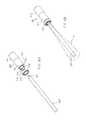
- FIG. 8Ais an exploded perspective view of the magnetic assembly, locking pin, bearing, and lead screw.
- FIG. 8Bis a perspective view illustrating the magnetic assembly coupled to the lead screw via the locking pin (hidden by the bearing).
- the off axis wiggle of the lead screwis illustrated by the cone-shaped envelope a.
- FIG. 9Ais an end view of the magnetic assembly.
- FIG. 9Bis a side view of the magnetic assembly.
- FIG. 9Cis a cross-sectional view of the magnetic assembly illustrated in FIG. 9B taken along the line C-C.
- FIG. 10illustrates a perspective view of an external adjustment device according to one embodiment.
- the outer housing or coveris removed to illustrate the various aspects of the external adjustment device.
- FIG. 11illustrates a side or end view of the external adjustment device of FIG. 10 .
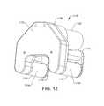
- FIG. 12illustrates a perspective view of an external adjustment device of FIG. 10 with the outer housing or cover in place.
- FIG. 13Aillustrates a cross-sectional representation of the external adjustment device being positioned on a patient's skin.
- FIG. 13Aillustrates the permanent magnet in the 0° position.
- FIG. 13Billustrates a cross-sectional representation of the external adjustment device being positioned on a patient's skin
- FIG. 13Billustrates the permanent magnet in the 90° position.
- FIG. 13Cillustrates a cross-sectional representation of the external adjustment device being positioned on a patient's skin.
- FIG. 13Cillustrates the permanent magnet in the 180° position.
- FIG. 13Dillustrates a cross-sectional representation of the external adjustment device being positioned on a patient's skin.
- FIG. 13Dillustrates the permanent magnet in the 270° position.
- FIG. 14schematically illustrates a system for driving the external adjustment device according to one embodiment.
- FIG. 1illustrates a patient 100 with scoliosis.
- the concave portion 102 of the spinal curvecan be seen on the left side 104 of the patient 100
- the convex portion 106can be seen on the right side 108 of the patient 100 .
- the concave portion 102may appear on the right side 108 of the patient 100 while the convex portion 106 may be found on the left side 104 of the patient.
- some rotation of the spine 110is present, and unevenness between the left shoulder 112 and right shoulder 114 is seen.
- FIG. 2illustrates the Cobb angle 116 of a spine 110 of a patient with scoliosis.
- lines 118 and 120are drawn from vertebra 122 and 124 , respectively.
- Intersecting perpendicular lines 126 and 128are drawn by creating 90° angles 130 and 132 from lines 118 and 120 .
- the angle 116 created from the crossing of the perpendicular lines 126 and 128is defined as the Cobb angle. In a perfectly straight spine, this angle is 0°.
- FIG. 3illustrates a long incision 134 formed in the patient 100 which is typically made during posterior scoliosis fusion surgery.
- This type of fusion surgeryis known in the prior art.
- the long incision 134extends between an upper end 136 and a lower end 138 .
- the length of this incision 134is longer than the length of the section of the vertebra to be fused.
- the actual length between the upper end 136 and the lower end 138varies, depending on the size of the patient, and the extent of the scoliosis, but in AIS patients this length is significantly longer than 15 cm. More typically, it is longer than 25 cm.
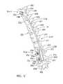
- FIG. 4illustrates a distraction device 200 for treating scoliosis according to one embodiment of the invention.
- the distraction device 200which is an implantable device, is fixated at its upper end 202 and lower end 204 to the patient's spine 500 .
- the illustrated example of the spine 500includes the particular thoracic and lumbar vertebrae that typically encompass a scoliotic curve, for example the curve of a patient with adolescent idiopathic scoliosis.
- T3 through T12 thoracic vertebrae, 503 , 504 , 505 , 506 , 507 , 508 , 509 , 510 , 511 , 512 , respectively and the L1 through L3 vertebrae, 513 , 514 , 515are depicted in FIG. 4 , not in a severe scoliotic condition, but in a very slight residual curve that represents a modest curve that has been partially or completely straightened during the implantation procedure.
- each vertebrais different from the other vertebra by its size and shape, with the upper vertebra generally being smaller than the lower vertebra.
- the vertebraehave a similar structure and include a vertebral body 516 , a spinous process 518 , 520 , laminae 526 , transverse processes 521 , 522 and pedicles 524 .
- the distraction device 200includes a distraction rod 206 which is adjustable (lengthwise) via a coupled adjustable portion 208 .
- the distraction device 200is fixated to the spine 500 via a clamp 600 at the upper end 202 of the distraction rod 206 .
- the clamp 600is secured around the transverse process 521 of the T4 vertebra 504 .
- the clamp 600may be secured around an adjacent rib (not shown) or rib facet.
- the clampmay be replaced by a laminar and pedicle hook system, or pedicle screw system. Exemplary pedicle hook systems or pedicle screw systems may be found in U.S. patent application Ser. Nos. 12/121,355 and 12/250,442 which are incorporated by reference as if set forth fully herein.
- the distraction device 200is illustrated as being fixated to the spine 500 with a pedicle screw system 531 comprising a connecting rod 532 and two toe clamps 538 , 540 .
- the connecting rod 532is shown curving back on itself in the shape of a “J.”
- the connecting rod 532then interfaces with the adjustable portion 208 .
- the adjustable portion 208preferably contains a magnetic assembly having a permanent magnet configured to drive a lead screw that, depending on the direction of rotation of the internal magnet, will extend or retract the distraction rod 206 using the adjustable portion 208 . Lengthening of the distraction rod 206 , for example, will impart a distraction force to the spine 500 . Retracting the distraction rod 206 will lower or remove the distraction force on the spine 500 , for example if too high a distraction force causes pain or complications.
- a locking screw 534can be loosened to adjust the angle of the connecting rod 532 into the desired orientation and then locking screw 534 can be tightened so that toe clamp 538 securely holds connecting rod 532 in place without further rotation.
- the second toe clamp 540is adjusted in the same way, by tightening locking screw 536 . Because a scoliotic spine is also rotated (usually the center section is rotated to the right in AIS patients), the non-fusion embodiment presented here allows de-rotation of the spine 500 to happen naturally, because there is no fixation at the middle portion of the distraction device 200 .
- the distraction device 200may allow for free rotation at its ends.
- the adjustable portion 208may be coupled to the connecting rod 532 via an articulating joint.
- U.S. patent application Ser. Nos. 12/121,355 and 12/250,442describe various articulating interfaces and joints that may be utilized to couple the adjustable portion 108 to the connecting rod 532 or the like.
- distraction rod 206may be precurved with the typical shape of a normal saggital spine, but it should also be noted that the curve may be slightly different than standard scoliosis fusion instrumentation, because in the non-fusion embodiment described herein, the distraction device 200 is not flush with the spine but rather is placed either subcutaneous or sub-fascial, and thus is not below the back muscles.
- the only portions of the distraction device 200 that are designed to be placed below the musclesare the clamp 600 and the portion of the distraction rod 206 immediately adjacent the clamp 600 , the pedicle screw system 531 and the connecting rod 532 .
- FIG. 4illustrates an embodiment in which the bulk of the hardware associated with the distraction device 200 is placed over the muscle.
- any other part of the entire implantable embodimentmay be placed under the muscle (i.e., sub-muscular). It should be appreciated that a much smaller amount of muscle needs to be dissected during the procedure in comparison with current fusion procedures. This will allow for a much shorter procedure, much less blood loss, much quicker recovery, and less time in the hospital/less risk of infection. Further, it may be desirable to produce the “J” curve of the connecting rod 532 or any other curve at the connecting rod 532 with optional flanges or ribs at their highest stress points in order to increase their durability in demanding implant conditions.
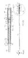
- FIGS. 5A-5Cillustrate cross-sectional views of the interface of the distraction rod 206 with the adjustable portion 208 .
- FIG. 5Ais a cross-sectional view of the distraction rod 206 and adjustable portion 208 taken along a perpendicular axis to the longitudinal axis of the distraction rod 206 .
- FIG. 5Billustrates a cross-sectional view of the distraction rod 206 and the adjustable portion 208 taken along the line B′-B of FIG. 5A .
- FIG. 5Cillustrates an enlarged cross-sectional view of detail C of FIG. 5B .
- an end 210 of the distraction rod 206includes an elongate recess 212 .
- the elongate recess 212may have a length of around 60 mm
- the recess 212is dimensioned to receive a lead screw 260 .
- the lead screw 260may be made from a high strength material such as, for example, titanium. At least a portion of the lead screw 260 includes external threads 262 that are configured to engage with a nut 214 integrated into the recess 212 .
- the nut 214provides a threaded portion on the recess 212 of the distraction rod 206 .
- the lead screw 260may have, for example, 80 threads per inch although more or less could be used.
- the nut 214may include threads or a chamfered surface 216 on the outer diameter in order to better ensure a secure attachment to the inner diameter of the recess 212 of the distraction rod 206 .
- the nut 214may be bonded to the distraction rod 206 using an adhesive such as EPOTEK 353ND, available from EPOXY TECHNOLOGY, INC., 14 Fortune Drive, Billerica, Mass. This allows the distraction rod 206 to be fabricated from a single piece of stronger material. It also provides for clearance between the lead screw 260 and internal diameter of the distraction rod 206 .
- a threaded portionmay be directly formed in the recess 212 without the aid of a separate nut 214 .
- FIGS. 6A-6Cillustrate separate views of the nut 214 .
- the nutincludes internal threads 218 that engage with the outer threads 262 of the lead screw 260 .
- the nut 214is made from aluminum-bronze #630.
- dissimilar metalstitanium for lead screw 260 and aluminum-bronze for the nut 214
- wet or dry lubricantsmay be used to reduce friction between the lead screw 260 and the nut 214 .
- a wet lubricantincludes biocompatible silicone oil such as MED-360 (100,000 cp) available from NuSil Technology, 1050 Cindy Lane, Carpinteria, Calif. 93013.
- the end of the distraction rod 206includes a splined tip 220 that includes one or more protrusions 222 that interface with corresponding longitudinal grooves 224 (not shown in FIG. 5C ) disposed within an inner surface of a tubular housing 226 .
- FIG. 7Aillustrates a perspective view of the splined tip 220 .
- the splined tip 220is illustrated with four (4) protrusions 222 that interface with four (4) corresponding longitudinal grooves 224 (two pairs in symmetric opposition) formed inside a tubular housing 226 (illustrated in FIGS. 7B-D ).
- the longitudinal grooves 224may be formed by wire EDM machining. While FIGS.
- FIG. 7A-7Dillustrate an embodiment that uses four (4) protrusions 222 along with four (4) longitudinal grooves 224 there may be more or less.
- the tight tolerance of the splined tip 220 with the longitudinal grooves 224keeps the distraction rod 206 centered within the tubular housing 226 .
- the combination of the splined tip 220 and corresponding grooves 224act as an anti-rotation feature that prevents the distraction rod 206 from rotating relative to the tubular housing 226 . This may be necessary to allow the distraction device 200 to be “rigidized” in the event the device is used in fusion applications, instead of the non-fusion applications described.
- the spine 500in a fusion application, it is desired that the spine 500 not be able to flex or rotate much during the months that the fusion is taking place.
- the anti-rotation featuresprevent inadvertent extension and/or retraction of the distraction rod 206 resulting from, for instance, patient movements.
- FIG. 7Cis a cross-sectional view of the tubular housing 226 taken along the line C-C in FIG. 7B .
- FIG. 7Dillustrates a magnified view of detail D of FIG. 7C .
- small reliefs 228are incorporated into the sides or corners of the longitudinal grooves 224 . These reliefs 228 may be slight over cut wire EDM notches that prevent the corners of the protrusions 222 from contacting the inner wall of the tubular housing 226 . Less contact between the protrusions 222 and the longitudinal grooves 224 results in less frictional forces and reduces the likelihood of binding.
- the tops of the protrusions 222could be curved, for example, cut from a diameter instead of a square. This rounding of the protrusions 222 would keep the protrusions 222 from binding with the longitudinal grooves 224 when torsional stresses are imparted between the distraction rod 206 and the adjustable portion 208 .
- This optional modificationmakes the distraction rod 106 easier to manufacture and eliminates the need for the relief 228 overcuts.
- an o-ring gland 230is affixed or otherwise bonded to an end of the tubular housing 226 .
- the o-ring gland 230is, for example, electron beam (e-beam) or laser welded to the end of the tubular housing 226 .
- the o-ring gland 230has an inner diameter than is less than inner diameter of the tubular housing.
- a stop 231is created that prevents further advancement of the splined tip 220 from exiting the tubular housing 226 .
- the o-ring gland 230further includes a recess 232 that is dimensioned to receive an o-ring 234 .
- the o-ring 234may be formed from a biocompatible material such as 70 durometer ethylene propylene diene M-class rubber (EPDM) available from Precision Associates, Inc., 740 North Washington Ave., Minneapolis, Minn., 55401-1188.
- the o-ring 234may have an inner diameter of around 0.241 inches+/ ⁇ 0.005 inches with a cross-section of 0.030 inches+/ ⁇ 0.003 inches.
- the outer diameter of the end 210 of the distraction rod 206may be around 0.25 inches.
- a biocompatible lubricantsuch as biocompatible silicone oil (e.g., MED-360 available from NuSil Technology) may be applied to the o-ring 234 .
- the o-ring 234thus forms a fluid-tight seal with the outer surface of the distraction rod 206 .
- the distraction rod 206is able to telescope relative to the housing 226 while simultaneously preventing foreign matter from entering the housing 226 .
- a single o-ring 234is illustrated in FIG. 5C
- multiple o-ringsmay also be used to provide additional confidence in seal integrity.
- the radial compression of the o-ringis greater than 7%, and preferably falls within the range between about 13% to 18%.
- the fill volume of the recess 232 of the o-ring gland 230is designed to be less than 75% in all cases and more particularly, within a range of about 40% to about 54%. It is desired to have all surfaces that contact the o-ring 234 be smooth.
- the recess 232may be designed with a smooth surface finish. Rough finishes can damage the o-ring 234 or provide a potential leakage path across sealing surfaces.
- An exemplary surface finishis 16 microinches RMS.
- the o-ring 234may provide several advantages in keeping foreign materials out of the tubular housing 226 .
- positive air pressure within the tubular housing 226may be created during the manufacturing process.
- the positive air pressureprovides additional stored pushing force to aid in distraction of the distraction rod 206 .
- the positive air pressurealso aids in preventing ingress of foreign matter.
- the use of the o-ring 234 within the recess 232 of the o-ring gland 230permits telescopic movement of the distraction rod 206 while at the same time seals in the interior of the tubular housing 226 from the exterior environment. In vivo animal testing has confirmed that such an arrangement has maintained the integrity of the tubular housing 226 for over seven months. In a seven month study conducted in vivo in pigs, the distraction device 200 was removed and the adjustable portion 208 was fully functional.
- the distraction rod 206is coupled to a magnetic assembly 236 via a locking pin 238 .
- the lead screw 260contains an aperture 264 transversely oriented with respect to the longitudinal axis of the lead screw 260 at the proximal end that is dimensioned to receive the locking pin 238 .
- the magnetic assembly 236which is described in more detail below, includes an upper cup 240 and a lower cup 242 .
- the upper cup 240terminates at a receptacle 244 that has an inner diameter dimensioned to receive the end of the lead screw 260 containing the aperture 264 .
- the receptacle 244also has an outer diameter that interfaces with an interior surface a bearing 246 .
- the bearing 246may include a radial ball bearing that rotatably holds the upper cup 240 (via the receptacle 244 ) within the tubular housing 226 .
- the receptacle 244includes apertures 248 , 249 through which the locking pin 238 is placed to lock the lead screw 260 to the magnetic assembly 236 .
- the locking pin 238remains in place because, when in place, the bearing 246 prevents the locking pin 238 from sliding out of the apertures 248 , 249 in the receptacle 244 .
- This overlapalso advantageously shortens the overall length of the magnetic assembly 236 .
- only a single aperture 248may be used and the opposing end of the locking pin 238 may interface with a recess located on the opposing side of the receptacle 244 .
- the interface between the lead screw 260 and the magnetic assembly 236has several functions.
- the interfacemust withstand heavy compressive loads. It also may need to withstand large tensile loads.
- the interfacemust transmit torque from the rotating magnetic assembly 236 to the lead screw 260 .
- the interfacemust also maintain the concentric alignment between the lead screw 260 and the nut 214 . With respect to compressive loads, these are transmitted down the lead screw 260 and across the locking pin 238 and into the magnetic assembly 236 .
- the magnetic assembly 236rides on a thrust ball bearing 250 .
- An end cap 252 located at one end of the tubular housing 226is provided.
- the end cap 252may be laser or e-beam welded to the tubular housing 226 .
- the end cap 252may be used to couple or otherwise interface with a joint (e.g., articulating joint) that is coupled or otherwise connected to, for example, a connecting rod 532 such as that illustrated in FIG. 4 .
- the locking pin 238pulls on the magnetic assembly which is retained by the bearing 246 .
- the locking pin 238may be made from a strong material such as, for instance, 440C stainless steel that has been heat treated for added strength. For instance, the 440C stainless steel may be heated to achieve a hardness of at least C58 Rockwell.
- the locking pin 238may have a length of around 0.185 inches and a diameter of around 0.0314 inches. The ends of the locking pin 238 may be beveled. The ultimate pull strength at which the locking pin 238 fails has been determined in testing to be 353 lbs.
- the locking pin 238retains its structural integrity up to a tensile load force of about 350 lbs. This is significantly higher than the highest expected distraction force. For example, other researchers have found that peak distraction forces experienced by growing rods are at or less than 124 lbs. See Teli et al., Measurement of Forces Generated During Distraction of Growing Rods, J. Child Orthop 1:257-258 (2007). The locking pin 238 described herein thus provides a wide margin of safety given the anticipated distraction forces that are experienced by the distraction rod 206 .
- FIG. 8Billustrates the cone-shaped envelope a traced by the off axis “wiggle” permitted by the interface of the locking pin 238 with the lead screw 260 . This wiggle or play allows the lead screw 260 and nut 214 to self-align to reduce binding.
- FIGS. 9A-9Cillustrate the magnetic assembly 236 .
- FIG. 9Aillustrates an end view of the magnetic assembly 236 while FIG. 9B illustrates a side view of the magnetic assembly 236 .
- FIG. 9Cis a cross-sectional view of the magnetic assembly 236 taken along the line C′-C of FIG. 9B .
- the magnetic assembly 236includes an upper cup 240 and a lower cup 242 .
- a permanent magnet 254is located in the recess formed between the interior portions of the upper cup 240 and the tower cup 242 .
- the permanent magnet 254is preferably a cylindrical magnet having a diameter of about 0.28 inches and a length of about 0.73 inches although other dimensions may be used.
- the permanent magnet 254may include, for example, a rare earth magnet formed from, for instance, Neodynium-Iron-Boron.
- the magnetmay be made from a grade of N35 or higher, for example a grade of N50.
- the permanent magnet 254is bonded or otherwise affixed to the upper cup 240 and the tower cup 242 .
- An epoxy adhesivesuch as EPOTEK 353ND may be used to bond the permanent magnet 254 to the upper cup 240 and the tower cup 242 . This allows torque applied to the permanent magnet 254 to be transferred to the upper cup 240 and thus the lead screw 260 .
- the permanent magnet 254is shorter in length than the combined lengths of the internal cavities of the upper cup 240 and lower cup 242 . This assures that when the magnetic assembly 236 is under compression, the upper cup 240 and the lower cup 242 are stressed instead of the permanent magnet 254 .
- FIG. 10illustrates an external adjustment device 1130 that may be used to externally impart rotational motion or “drive” the magnetic assembly 236 located within the distraction device 200 .
- the external adjustment device 1130includes a motor 1132 that is used to impart rotational movement to two permanent magnets 1134 , 1136 .
- the two permanent magnets 1134 , 1136are located in the same driver 1130 and are configured for placement on the same side of the body of the patient or subject.
- the motor 1132may include, for example, a DC powered motor or servo that is powered via one or more batteries (not shown) integrally contained within the external adjustment device 1130 .
- the motor 1132may be powered via a power cord or the like to an external power source.
- the external power sourcemay include one or more batteries or even an alternating current source that is converted to DC.
- the two permanent magnets 1134 , 1136are preferably cylindrically-shaped permanent magnets.
- the permanent magnetsmay be made from, for example, a rare earth magnet material such as Neodymium-Iron-Boron (NdFeB) although other rare earth magnets are also possible.
- each magnet 1134 , 1136may have a length of around 1.5 inches and a diameter of around 1.0 to 3.5 inches.
- Both magnets 1134 , 1136are diametrically magnetized (poles are perpendicular the longitudinal axis of each permanent magnet 1134 , 1136 ).
- the magnets 1134 , 1136may be contained within a non-magnetic cover or housing 1137 .
- the magnets 1134 , 1136are able to rotate within the stationary housing 1137 that separates the magnets 1134 , 1136 from the external environment.
- the housing 1137is rigid and relatively thin walled at least at the portion directly covering the permanent magnets 1134 , 1136 , in order to minimize the gap between the permanent magnets 1134 , 1136 and the magnetic assembly 236 (as shown in FIGS. 13A-13D ).
- the permanent magnets 1134 , 1136are rotationally mounted between opposing bases members 1138 , 1140 .
- Each magnet 1134 , 1136may include axles or spindles 1142 , 1144 mounted on opposing axial faces of each magnet 1134 , 1136 .
- the axles 1142 , 1144may be mounted in respective bearings (not shown) that are mounted in the base members 1138 , 1140 .
- driven pulleys 1150are mounted on one set of axles 1142 and 1144 .
- the driven pulleys 1150may optionally include grooves or teeth 1152 that are used to engage with corresponding grooves or teeth 1156 (partially illustrated in FIG. 11 ) contained within a drive belt (indicated by path 1154 ).
- the external adjustment device 1130includes a drive transmission 1160 that includes the two driven pulleys 1150 along with a plurality of pulleys 1162 A, 1162 B, 1162 C and rollers 1164 A, 1164 B, 1164 C on which the drive belt 1154 is mounted.
- the pulleys 1162 A, 1162 B, 1162 Cmay optionally include grooves or teeth 1166 used for gripping corresponding grooves or teeth 1156 of the drive belt 1154 .
- Pulleys 1162 A, 1162 B, 1162 C and rollers 1164 A, 1164 B, 1164 Cmay be mounted on respective bearings (not shown). As seen in FIG.
- pulley 1162 Bis mechanically coupled to the drive shaft (not shown) of the motor 1132 .
- the pulley 1162 Bmay be mounted directly to the drive shaft or, alternatively, may be coupled through appropriate gearing.
- One roller 1164 Bis mounted on a biased arm 1170 and thus provides tension to the belt 1154 .
- the various pulleys 1150 , 1162 A, 1162 B, 1162 C and rollers 1164 A, 1164 B, 1164 C along with the drive belt 1154may be contained within a cover or housing 1172 that is mounted to the base 1138 (as seen in FIG. 12 ).
- the external adjustment device 1130may have a removable safety cover that would be placed over the portion containing the permanent magnets 1134 , 1136 , for example during storage, so that the high magnetic field cannot come closely in contact with anything that would be strongly attracted to it or damaged by it.
- the external adjustment device 1130may also be supplied in a case, for example, a case that has a sheet made of a magnetic shielding material, to minimize the magnetic field external to the case. Giron or mu-metal are two examples of this material.
- rotational movement of the pulley 1162 Bcauses the drive belt 1154 to move around the various pulleys 1150 , 1162 A, 1162 B, 1162 C and rollers 1164 A, 1164 B, 1164 C.
- rotational movement of the motor 1132is translated into rotational movement of the two permanent magnets 1134 , 1136 via the drive transmission 1160 .
- the base members 1138 , 1140are cut so as to form a recess 1174 that is located between the two magnets 1134 , 1136 .
- the external adjustment device 1130is pressed against the skin of a patient, or against the clothing which covers the skin (e.g., the external adjustment device 1130 may be used through clothing so the patient may not need to undress).
- a small permanent magnetmay be placed on the patient's clothing to determine the location of the implanted permanent magnet 254 (via the attraction of the two magnets).
- the recess 1174allows skin as well as the underlying tissue to gather or compress within the recessed region 1174 as seen in FIGS. 13A and 13B . This advantageously reduces the overall distance between the external drive magnets 1134 , 1136 and the permanent magnet 254 contained within the magnetic assembly 236 of the distraction device 200 . By reducing the distance, this means that the externally located magnets 1134 , 1136 and/or the internal magnet 1064 may be made smaller. This is especially useful in the case of an obese patient.
- the two permanent magnets 1134 , 1136are configured to rotate at the same angular velocity.
- the two permanent magnets 1134 , 1136each have at least one north pole and at least one south pole, and the external adjustment device 1130 is configured to rotate the first magnet 1134 and the second magnet 1136 such that the angular location of the at least one north pole of the first magnet 1134 is substantially equal to the angular location of the at least one south pole of the second magnet 1136 through a full rotation of the first and second magnets 1134 , 1136 .
- FIGS. 13A and 13Billustrate cross-sectional views of the patient having an implanted distraction device (not shown for sake of clarity) with a permanent magnet 254 contained within a magnetic assembly 236 (not shown in FIGS. 13A and 13B for clarity sake).
- the internal permanent magnet 254is seen disposed on one side of a vertebra 1185 . Further, the internal permanent magnet 254 is seen being outside or external with respect to the fascia 1184 and muscle 1186 of the subject.
- FIGS. 13A and 13Billustrate an obese patient in which skin and other tissue gather within the recess 1174 . It should be understood that obese Adolescent Idiopathic Scoliosis patients are rare, and FIGS. 13A and 13B generally indicate a worst-case situation but as seen in FIGS.
- the excess skin and other tissueare easily accommodated within the recess 1174 to enable close positioning between the internal permanent magnet 254 and the external drive magnets 1134 , 1136 .
- the air gap or distance between the internal permanent magnet 254 and the external drive magnets 1134 , 1136is generally one inch or less.
- the internal permanent magnet 254is depicted somewhat larger than its actual size in order for its respective poles to be more clearly visible.
- the external adjustment device 1130preferably includes an encoder 1175 that is used to accurately and precisely measure the degree of movement (e.g., rotational) of the external magnets 1134 , 1136 .
- an encoder 1175is mounted on the base member 1138 and includes a light source 1176 and a light receiver 1178 .
- the light source 1176may include a LED which is pointed or directed toward pulley 1162 C.
- the light receiver 1178may be directed toward the pulley 1162 C.
- the pulley 1162 Cincludes a number of reflective markers 1177 regularly spaced about the periphery of the pulley 1162 C.
- the digital on/off signal generated by the light receiver 1178can then be used to determine the rotational speed and displacement of the external magnets 1134 , 1136 .
- FIGS. 13A, 13B, 13C, and 13Dillustrate the progression of the external magnets 1134 , 1136 and the internal permanent magnet 254 that is located within the distraction device 200 during use.
- FIGS. 13A, 13B, 13C, and 13Dillustrate the external adjustment device 1130 being disposed against the external surface of the patient's skin 1180 adjacent the spine.
- the patient 100lies in a prone position, and the external adjustment device 1130 is placed upon the patient's back.
- the external adjustment device 1130is placed against the skin 1180 in this manner to remotely rotate the internal permanent magnet 254 .
- rotation of the internal permanent magnet 254causes rotational movement of the magnetic assembly 236 .
- This rotational movementis then translated to the lead screw 260 via the locking pin 238 that connects the lead screw 260 to the magnetic assembly 236 .
- the distraction rod 206moves in a telescopic manner out of or into the adjustable portion 208 .
- the magnetic assembly 236may have rotational movement though less than 360° of a full rotation of the magnetic assembly 236 .
- the magnetic assembly 236may have rotational movement through more than 360° (e.g., multiple, fill revolutions).
- the external adjustment device 1130may be pressed down on the patient's skin 1180 with some degree of force such that skin 1180 and other tissue such as the underlying layer of fat 1182 are pressed or forced into the recess 1174 of the external adjustment device 1130 .
- FIGS. 13A, 13B, 13C, and 13Dshow the magnetic orientation of the internal permanent magnet 254 as it undergoes a full rotation in response to movement of the permanent magnets 1134 , 1136 of the external adjustment device 1130 .
- the internal permanent magnet 254is shown being oriented with respect to the two permanent magnets 1134 , 1136 via an angle ⁇ .
- This angle ⁇may depend on a number of factors including, for instance, the separation distance between the two permanent magnets 1134 , 1136 , the location or depth of where the implantable interface 1104 is located, the degree of force at which the external adjustment device 1130 is pushed against the patient's skin Generally in applications including some obese patients, the angle ⁇ should be at or around 90° to achieve maximum drivability (e.g., torque).
- the inventorshave calculated that in the AIS application, where there are few obese patients, an angle of about 70° is preferred for the majority of patients when the permanent magnets 1134 , 1136 have an outer diameter of about two (2.0) to three (3.0) inches.
- FIG. 13Aillustrates the initial position of the two permanent magnets 1134 , 1136 and the internal permanent magnet 254 .
- Thisrepresents the initial or starting location (e.g., 0° position as indicated).
- the particular orientation of the two permanent magnets 1134 , 1136 and the internal permanent magnet 254will vary and not likely will have the starting orientation as illustrated in FIG. 13A .
- the two permanent magnets 1134 , 1136are oriented with their poles in an N-S/S-N arrangement.
- the internal permanent magnet 254is, however, oriented generally perpendicular to the poles of the two permanent magnets 1134 , 1136 .
- FIG. 13Billustrates the orientation of the two permanent magnets 1134 , 1136 and the internal permanent magnet 254 after the two permanent magnets 1134 , 1136 have rotated through 90°.
- the two permanent magnets 1134 , 1136rotate in the direction of arrow A (e.g., clockwise) while the internal permanent magnet 254 rotates in the opposite direction (e.g., counter clockwise) represented by arrow B.
- the two permanent magnets 1134 , 1136may rotate in the counter clockwise direction while the internal permanent magnet 254 may rotate in the clockwise direction.
- Rotation of the two permanent magnets 1134 , 1136 and the internal permanent magnet 254continues as represented by the 180° and 270° orientations as illustrated in FIGS. 13C and 13D . Rotation continues until the starting position) (0° is reached again.
- the permanent magnets 1134 , 1136may be driven to rotate the internal permanent magnet 254 through one or more full rotations in either direction to increase or decrease distraction of the distraction device 200 as needed.
- the permanent magnets 1134 , 1136may be driven to rotate the internal permanent magnet 254 through a partial rotation as well (e.g., 1 ⁇ 4, 1 ⁇ 8, 1/16, etc.).
- the use of two magnets 1134 , 1136is preferred over a single external magnet because the internal permanent magnet 254 may not be oriented perfectly at the start of rotation, so one external magnet 1134 , 1136 may not be able to deliver its maximum torque, which depends on the orientation of the internal permanent magnet 254 to some degree.
- one of the two 1134 or 1136will have an orientation relative to the internal permanent magnet 254 that is better or more optimal than the other.
- the torques imparted by each external magnet 1134 , 1136are additive.
- the external driving deviceis at the mercy of the particular orientation of the internal driven magnet.
- the two-magnet embodiment described hereinis able to guarantee a larger driving torque—as much as 75% more than a one-magnet embodiment in the AIS application—and thus the internal permanent magnet 254 can be designed smaller in dimension, and less massive.
- a smaller internal permanent magnet 254have a smaller image artifact when performing MRI (Magnetic Resonance Imaging), especially important when using pulse sequences such as gradient echo, which is commonly used in breast imaging, and leads to the largest artifact from implanted magnets.
- MRIMagnetic Resonance Imaging
- FIG. 14illustrates a system 1076 according to one aspect of the invention for driving the external adjustment device 1130 .
- FIG. 14illustrates the external adjustment device 1130 pressed against the surface of a patient 1077 (torso face down shown in cross-section). The portion of the distraction device 200 containing the internal permanent magnet 254 is illustrated.
- the permanent magnet 254 that is located within the magnetic assembly 236 (disposed internally within the patient 1077is magnetically coupled through the patient's skin and other tissue to the two external magnets 1134 , 1136 located in the external adjustment device 1130 .
- one rotation of the external magnets 1134 , 1136causes a corresponding single rotation of the magnetic assembly 236 (which contains the permanent magnet 254 ).
- Turning magnetic assembly 236 in one directioncauses the distraction device 200 to lengthen, or increase distraction force while turning in the opposite direction causes the distraction device 200 to shorten, or decrease distraction force. Changes to the distraction device 200 are directly related to the number of turns of the magnetic assembly 236 .
- the motor 1132 of the external adjustment device 1130is controlled via a motor control circuit 1078 operatively connected to a programmable logic controller (PLC) 1080 .
- the PLC 1080outputs an analog signal to the motor control circuit 1078 that is proportional to the desired speed of the motor 1132 .
- the PLC 1080may also select the rotational direction of the motor 1132 (i.e., forward or reverse).
- the PLC 1080receives an input signal from a shaft encoder 1082 that is used to identify with high precision and accuracy the exact relative position of the external magnets 1134 , 1136 .
- the shaft encoder 1082may be an encoder 1175 as described in FIGS. 10-11 .
- the signalis a pulsed, two channel quadrature signal that represents the angular position of the external magnets 1134 , 1136 .
- the PLC 1080may include a built in screen or display 1081 that can display messages, warnings, and the like.
- the PLC 1080may optionally include a keyboard 1083 or other input device for entering data.
- the PLC 1080may be incorporated directly into the external adjustment device 1130 or it may be a separate component that is electrically connected to the main external adjustment device 1130 .
- a sensor 1084is incorporated into the external adjustment device 1130 that is able to sense or determine the rotational or angular position of the internal permanent magnet 254 .
- the sensor 1084may acquire positional information using, for example, sound waves, ultrasonic waves, light, radiation, or even changes or perturbations in the magnetic or electromagnetic field between the internal permanent magnet 254 and the external magnets 1134 , 1136 .
- the sensor 1084may detect photons or light that is reflected from the internal permanent magnet 254 or a coupled structure (e.g., rotor) that is attached thereto.
- lightmay be passed through the patient's skin and other tissue at wavelength(s) conducive for passage through tissue.
- Portions of the internal permanent magnet 254 or associated structuremay include a reflective surface that reflects light back outside the patient as the internal permanent magnet 254 moves. The reflected light can then be detected by the sensor 1084 which may include, for example, a photodetector or the like.
- the senor 1084may operate on the Hall effect, wherein two additional magnets are located within the implantable assembly.
- the additional magnetsmove axially in relation to each other as the internal permanent magnet 254 rotates and therefore as the distraction increases or decreases, allowing the determination of the current size of the restriction device.
- the sensor 1084is a microphone disposed on the external adjustment device 1130 .
- the microphone sensor 1084may be disposed in the recessed portion 1174 of the external adjustment device 1130 .
- the output of the microphone sensor 1084is directed to a signal processing circuit 1086 that amplifies and filters the detected acoustic signal.
- the acoustic signalmay include a “click” or other noise that is periodically generated by rotation of the internal permanent magnet 254 .
- the internal permanent magnet 254may click every time a full rotation is made.
- the pitch (frequency) of the clickmay differ depending on the direction of rotation.
- rotation in one directionmay produce a low pitch while rotation in the other direction (e.g., shortening) may produce a higher pitch signal (or vice versa).
- the amplified and filtered signal from the signal processing, circuit 1086can then pass to the PLC 1080 . Additional details regarding the operation of various acoustic and other detection modalities may be found in U.S. patent application Ser. No. 12/121,355.
- each patientwill have a number or indicia that correspond to the adjustment setting or size of their distraction device 200 .
- This numbercan be stored on an optional storage device 1088 (as shown in FIG. 14 ) that is carried by the patient (e.g., memory card, magnetic card, or the like) or is integrally formed with the distraction device 200 .
- a RFID tag 1088 implanted either as part of the system or separatelymay be disposed inside the patient (e.g., subcutaneously or as part of the device) and can be read and written via an antenna 1090 to update the current size of the distraction device 200 .
- the PLC 1080has the ability to read the current number corresponding to the size or setting of the distraction device 200 from the storage device 1088 .
- the PLC 1080may also be able to write the adjusted or more updated current size or setting of the distraction device 200 to the storage device 1088 .
- the current sizemay recorded manually in the patient's medical records (e.g., chart, card or electronic patient record) that is then viewed and altered, as appropriate, each time the patient visits his or her physician.
- the patienttherefore, carries their medical record with them, and if, for example, they are in another location, or even country, and need to be adjusted, the RFID tag 1088 has all of the information needed. Additionally, the RFID tag 1088 may be used as a security device. For example, the RFID tag 1088 may be used to allow only physicians to adjust the distraction device 200 and not patients. Alternatively, the RFID tag 1088 may be used to allow only certain models or makes of distraction devices to be adjusted by a specific model or serial number of external adjustment device 1130 .
- the current size or setting of the distraction device 200is input into the PLC 1080 . This may be done automatically or through manual input via, for instance, the keyboard 1083 that is associated with the PLC 1080 .
- the PLC 1080thus knows the patient's starting point. If the patient's records are lost, the length of the distraction device may be measured by X-ray and the PLC 1080 may be manually programmed to this known starting point.
- the external adjustment device 1130is commanded to make an adjustment. This may be accomplished via a pre-set command entered into the PLC 1080 (e.g. “increase distraction displacement of distraction device 200 by 0.5 cm” or “increase distraction force of distraction device 200 to 20 pounds”).
- the PLC 1080configures the proper direction for the motor 1132 and starts rotation of the motor 1132 .
- the encoder 1082is able to continuously monitor the shaft position of the motor directly, as is shown in FIG. 14 , or through another shaft or surface that is mechanically coupled to the motor 1132 .
- the encoder 1082may read the position of markings 1177 located on the exterior of a pulley 1162 C like that disclosed in FIG. 10 . Every rotation or partial rotation of the motor 1132 can then be counted and used to calculate the adjusted or new size or setting of the distraction device 200 .
- the sensor 1084which may include a microphone sensor 1084 , may be monitored continuously. For example, every rotation of the motor 1132 should generate the appropriate number and pitch of clicks generated by rotation of the permanent magnet inside the distraction device 200 . If the motor 1132 turns a full revolution but no clicks are sensed, the magnetic coupling may have been lost and an error message may be displayed to the operator on a display 1081 of the PLC 1080 . Similarly, an error message may be displayed on the display 1081 if the sensor 1084 acquires the wrong pitch of the auditory signal (e.g., the sensor 1084 detects a shortening pitch but the external adjustment device 1130 was configured to lengthen).
Landscapes
- Health & Medical Sciences (AREA)
- Orthopedic Medicine & Surgery (AREA)
- Life Sciences & Earth Sciences (AREA)
- Surgery (AREA)
- Neurology (AREA)
- Heart & Thoracic Surgery (AREA)
- Engineering & Computer Science (AREA)
- Biomedical Technology (AREA)
- Nuclear Medicine, Radiotherapy & Molecular Imaging (AREA)
- Medical Informatics (AREA)
- Molecular Biology (AREA)
- Animal Behavior & Ethology (AREA)
- General Health & Medical Sciences (AREA)
- Public Health (AREA)
- Veterinary Medicine (AREA)
- Physics & Mathematics (AREA)
- Electromagnetism (AREA)
- Surgical Instruments (AREA)
Abstract
Description
Claims (15)
Priority Applications (4)
| Application Number | Priority Date | Filing Date | Title |
|---|---|---|---|
| US14/332,286US9848914B2 (en) | 2009-02-23 | 2014-07-15 | Non-invasive adjustable distraction system |
| US15/820,067US10517643B2 (en) | 2009-02-23 | 2017-11-21 | Non-invasive adjustable distraction system |
| US16/678,977US11304729B2 (en) | 2009-02-23 | 2019-11-08 | Non-invasive adjustable distraction system |
| US17/654,291US11918254B2 (en) | 2009-02-23 | 2022-03-10 | Adjustable implant system |
Applications Claiming Priority (3)
| Application Number | Priority Date | Filing Date | Title |
|---|---|---|---|
| US12/391,109US8197490B2 (en) | 2009-02-23 | 2009-02-23 | Non-invasive adjustable distraction system |
| US13/477,945US8974463B2 (en) | 2009-02-23 | 2012-05-22 | Non-invasive adjustable distraction system |
| US14/332,286US9848914B2 (en) | 2009-02-23 | 2014-07-15 | Non-invasive adjustable distraction system |
Related Parent Applications (1)
| Application Number | Title | Priority Date | Filing Date |
|---|---|---|---|
| US13/477,945ContinuationUS8974463B2 (en) | 2009-02-23 | 2012-05-22 | Non-invasive adjustable distraction system |
Related Child Applications (1)
| Application Number | Title | Priority Date | Filing Date |
|---|---|---|---|
| US15/820,067ContinuationUS10517643B2 (en) | 2009-02-23 | 2017-11-21 | Non-invasive adjustable distraction system |
Publications (2)
| Publication Number | Publication Date |
|---|---|
| US20140343611A1 US20140343611A1 (en) | 2014-11-20 |
| US9848914B2true US9848914B2 (en) | 2017-12-26 |
Family
ID=42631615
Family Applications (7)
| Application Number | Title | Priority Date | Filing Date |
|---|---|---|---|
| US12/391,109Active2030-05-14US8197490B2 (en) | 2009-02-23 | 2009-02-23 | Non-invasive adjustable distraction system |
| US13/477,945Active2029-03-20US8974463B2 (en) | 2009-02-23 | 2012-05-22 | Non-invasive adjustable distraction system |
| US14/332,286Active2029-06-26US9848914B2 (en) | 2009-02-23 | 2014-07-15 | Non-invasive adjustable distraction system |
| US15/820,067Active2029-12-02US10517643B2 (en) | 2009-02-23 | 2017-11-21 | Non-invasive adjustable distraction system |
| US16/678,977Active2029-12-28US11304729B2 (en) | 2009-02-23 | 2019-11-08 | Non-invasive adjustable distraction system |
| US17/654,291Active2029-04-22US11918254B2 (en) | 2009-02-23 | 2022-03-10 | Adjustable implant system |
| US18/437,380ActiveUS12318119B2 (en) | 2009-02-23 | 2024-02-09 | Adjustable implant system |
Family Applications Before (2)
| Application Number | Title | Priority Date | Filing Date |
|---|---|---|---|
| US12/391,109Active2030-05-14US8197490B2 (en) | 2009-02-23 | 2009-02-23 | Non-invasive adjustable distraction system |
| US13/477,945Active2029-03-20US8974463B2 (en) | 2009-02-23 | 2012-05-22 | Non-invasive adjustable distraction system |
Family Applications After (4)
| Application Number | Title | Priority Date | Filing Date |
|---|---|---|---|
| US15/820,067Active2029-12-02US10517643B2 (en) | 2009-02-23 | 2017-11-21 | Non-invasive adjustable distraction system |
| US16/678,977Active2029-12-28US11304729B2 (en) | 2009-02-23 | 2019-11-08 | Non-invasive adjustable distraction system |
| US17/654,291Active2029-04-22US11918254B2 (en) | 2009-02-23 | 2022-03-10 | Adjustable implant system |
| US18/437,380ActiveUS12318119B2 (en) | 2009-02-23 | 2024-02-09 | Adjustable implant system |
Country Status (7)
| Country | Link |
|---|---|
| US (7) | US8197490B2 (en) |
| EP (2) | EP2398409B1 (en) |
| JP (4) | JP5896405B2 (en) |
| CN (3) | CN105078555B (en) |
| ES (1) | ES2861223T3 (en) |
| PL (1) | PL2398409T3 (en) |
| WO (1) | WO2010096315A1 (en) |
Cited By (10)
| Publication number | Priority date | Publication date | Assignee | Title |
|---|---|---|---|---|
| US20180296256A1 (en)* | 2015-10-16 | 2018-10-18 | Nuvasive Specialized Orthopedics, Inc. | Adjustable Devices for Treating Arthritis of the Knee |
| US10368918B2 (en) | 2011-03-01 | 2019-08-06 | Nuvasive, Inc. | Posterior cervical fixation system |
| US10456172B2 (en) | 2016-02-12 | 2019-10-29 | Nuvasive, Inc. | Magnetically actuateable rod insertion for minimally invasive surgery |
| US10610261B2 (en) | 2016-02-12 | 2020-04-07 | Nuvasive, Inc. | Post-operatively adjustable angled rod |
| US11291478B2 (en) | 2016-02-12 | 2022-04-05 | Nuvasive, Inc. | Post-operatively adjustable spinal fixation devices |
| US11446063B2 (en) | 2016-02-12 | 2022-09-20 | Nuvasive, Inc. | Post-operatively adjustable angled rod |
| US11918254B2 (en) | 2009-02-23 | 2024-03-05 | Nuvasive Specialized Orthopedics Inc. | Adjustable implant system |
| WO2024059465A1 (en) | 2022-09-13 | 2024-03-21 | Nuvasive Specialized Orthopedics, Inc. | Torque transfer mechanisms |
| US12232790B2 (en) | 2022-12-30 | 2025-02-25 | IvyTech Design LLC | Adjustable angle orthopedic distractor, compressor, and distractor-compressor |
| US12433649B2 (en) | 2019-02-13 | 2025-10-07 | The Trustees Of The University Of Pennsylvania | Systems and methods for a smart, implantable cranio-maxillo-facial distractor |
Families Citing this family (86)
| Publication number | Priority date | Publication date | Assignee | Title |
|---|---|---|---|---|
| US7955357B2 (en)* | 2004-07-02 | 2011-06-07 | Ellipse Technologies, Inc. | Expandable rod system to treat scoliosis and method of using the same |
| US8790380B2 (en)* | 2007-07-26 | 2014-07-29 | Dynamic Spine, Llc | Segmental orthopaedic device for spinal elongation and for treatment of scoliosis |
| US9204908B2 (en) | 2007-07-26 | 2015-12-08 | Dynamic Spine, Llc | Segmental orthopedic device for spinal elongation and for treatment of scoliosis |
| US20090112262A1 (en) | 2007-10-30 | 2009-04-30 | Scott Pool | Skeletal manipulation system |
| US11202707B2 (en) | 2008-03-25 | 2021-12-21 | Nuvasive Specialized Orthopedics, Inc. | Adjustable implant system |
| US11241257B2 (en) | 2008-10-13 | 2022-02-08 | Nuvasive Specialized Orthopedics, Inc. | Spinal distraction system |
| US8382756B2 (en) | 2008-11-10 | 2013-02-26 | Ellipse Technologies, Inc. | External adjustment device for distraction device |
| US9622792B2 (en) | 2009-04-29 | 2017-04-18 | Nuvasive Specialized Orthopedics, Inc. | Interspinous process device and method |
| CN102596097B (en) | 2009-06-03 | 2015-05-20 | 弗赛特实验室有限责任公司 | an eye insert |
| JP5751642B2 (en) | 2009-09-04 | 2015-07-22 | エリプス テクノロジーズ, インク.Ellipse Technologies, Inc. | Bone growth apparatus and method |
| WO2011044586A1 (en)* | 2009-10-10 | 2011-04-14 | Simplicity Orthopedics, Inc. | Method and apparatus for restoring a joint, including the provision and use of a longitudinally-adjustable and rotationally-adjustable joint prosthesis |
| JP2013512040A (en)* | 2009-11-25 | 2013-04-11 | スパイン21エル・ティー・ディー | Spinal rod with adjustable dimensions after surgery |
| US8398686B2 (en)* | 2009-11-27 | 2013-03-19 | Rahul Vaidya | Method and apparatus for minimally invasive subcutaneous treatment of long bone fractures |
| US8568457B2 (en)* | 2009-12-01 | 2013-10-29 | DePuy Synthes Products, LLC | Non-fusion scoliosis expandable spinal rod |
| FR2957776B1 (en)* | 2010-03-23 | 2013-02-15 | Arnaud Andre Soubeiran | DEVICE FOR MOVING TISSUES INSIDE THE ORGANISM, ESPECIALLY BONE TISSUES, WITH FIXED TRACTION SCREWS AND ROTATING NUT |
| AU2011264818B2 (en) | 2010-06-10 | 2015-06-18 | Globus Medical, Inc. | Low-profile, uniplanar bone screw |
| US9248043B2 (en) | 2010-06-30 | 2016-02-02 | Ellipse Technologies, Inc. | External adjustment device for distraction device |
| US8920471B2 (en) | 2010-07-12 | 2014-12-30 | K2M, Inc. | Transverse connector |
| AU2011331999B2 (en) | 2010-11-22 | 2016-07-21 | Synthes Gmbh | Non-fusion scoliosis expandable spinal rod |
| WO2012112396A2 (en) | 2011-02-14 | 2012-08-23 | Ellipse Technologies, Inc. | Device and method for treating fractured bones |
| US10743794B2 (en) | 2011-10-04 | 2020-08-18 | Nuvasive Specialized Orthopedics, Inc. | Devices and methods for non-invasive implant length sensing |
| US10016220B2 (en) | 2011-11-01 | 2018-07-10 | Nuvasive Specialized Orthopedics, Inc. | Adjustable magnetic devices and methods of using same |
| US10016226B2 (en) | 2011-12-12 | 2018-07-10 | Children's Hospital Medical Center Of Akron | Noninvasive device for adjusting fastener |
| US9949761B2 (en) | 2011-12-12 | 2018-04-24 | Children's Hospital Medical Center Of Akron | Noninvasive device for adjusting fastener |
| US9078711B2 (en)* | 2012-06-06 | 2015-07-14 | Ellipse Technologies, Inc. | Devices and methods for detection of slippage of magnetic coupling in implantable medical devices |
| US20130338714A1 (en) | 2012-06-15 | 2013-12-19 | Arvin Chang | Magnetic implants with improved anatomical compatibility |
| US9572601B2 (en)* | 2012-10-17 | 2017-02-21 | K2M, Inc. | Spinal correction adjustment systems and methods |
| US9044281B2 (en) | 2012-10-18 | 2015-06-02 | Ellipse Technologies, Inc. | Intramedullary implants for replacing lost bone |
| EP2911616B1 (en) | 2012-10-29 | 2020-10-07 | NuVasive Specialized Orthopedics, Inc. | Adjustable devices for treating arthritis of the knee |
| US9179938B2 (en)* | 2013-03-08 | 2015-11-10 | Ellipse Technologies, Inc. | Distraction devices and method of assembling the same |
| US9775650B2 (en)* | 2013-03-11 | 2017-10-03 | Dynamic Spine, Llc | Screw clamp orthopedic device and methods of implementation |
| US9615864B2 (en) | 2013-05-31 | 2017-04-11 | Rehabilitation Institute Of Chicago | Limb lengthening system for residual limb |
| US10226242B2 (en) | 2013-07-31 | 2019-03-12 | Nuvasive Specialized Orthopedics, Inc. | Noninvasively adjustable suture anchors |
| US9801734B1 (en) | 2013-08-09 | 2017-10-31 | Nuvasive, Inc. | Lordotic expandable interbody implant |
| FR3010628B1 (en) | 2013-09-18 | 2015-10-16 | Medicrea International | METHOD FOR REALIZING THE IDEAL CURVATURE OF A ROD OF A VERTEBRAL OSTEOSYNTHESIS EQUIPMENT FOR STRENGTHENING THE VERTEBRAL COLUMN OF A PATIENT |
| US10751094B2 (en) | 2013-10-10 | 2020-08-25 | Nuvasive Specialized Orthopedics, Inc. | Adjustable spinal implant |
| CN105813578A (en)* | 2013-10-15 | 2016-07-27 | 弗赛特影像5股份有限公司 | Formulations and methods for increasing or reducing mucus |
| FR3012030B1 (en) | 2013-10-18 | 2015-12-25 | Medicrea International | METHOD FOR REALIZING THE IDEAL CURVATURE OF A ROD OF A VERTEBRAL OSTEOSYNTHESIS EQUIPMENT FOR STRENGTHENING THE VERTEBRAL COLUMN OF A PATIENT |
| US9486252B2 (en)* | 2014-01-09 | 2016-11-08 | Warsaw Orthopedic, Inc. | Spinal correction system and method |
| US9289238B2 (en) | 2014-04-23 | 2016-03-22 | Texas Scottish Rite Hospital For Children | Dynamization module for external fixation strut |
| CN106456215B (en) | 2014-04-28 | 2020-04-10 | 诺威适骨科专科公司 | External adjustment device for adjusting a medical implant |
| US9931138B2 (en)* | 2014-10-15 | 2018-04-03 | Globus Medical, Inc. | Orthopedic extendable rods |
| KR102588501B1 (en) | 2014-10-23 | 2023-10-11 | 누베이시브 스페셜라이즈드 오소페딕스, 인크. | Remotely adjustable interactive bone reshaping implant |
| US9867656B2 (en)* | 2014-11-17 | 2018-01-16 | Covidien Lp | Multi-function surgical instruments |
| ES2908064T3 (en) | 2014-12-26 | 2022-04-27 | Nuvasive Specialized Orthopedics Inc | distraction systems |
| EP3283004A4 (en) | 2015-04-13 | 2018-12-05 | Forsight Vision5, Inc. | Ocular insert composition of semi-crystalline or crystalline pharmaceutically active agent |
| US10456211B2 (en) | 2015-11-04 | 2019-10-29 | Medicrea International | Methods and apparatus for spinal reconstructive surgery and measuring spinal length and intervertebral spacing, tension and rotation |
| FR3044888A1 (en)* | 2015-12-09 | 2017-06-16 | Ecole Nat Superieure De Techniques Avancees | PLATE DISTRACTOR AND ASSEMBLY OF SUCH A PLATE DISTRACTOR AND AN ACTIVATION TOOL |
| CN108601611B (en) | 2015-12-10 | 2021-11-02 | 诺威适骨科专科公司 | External adjustment device for stretcher |
| BR112018015504A2 (en) | 2016-01-28 | 2018-12-18 | Nuvasive Specialized Orthopedics, Inc. | bone transport systems |
| US10603076B2 (en) | 2016-02-03 | 2020-03-31 | Texas Scottish Rite Hospital For Children | Dynamization device for orthopedic fixation device |
| US9717530B1 (en)* | 2016-02-03 | 2017-08-01 | Texas Scottish Rite Hospital For Children | External fixation struts |
| WO2017139548A1 (en) | 2016-02-10 | 2017-08-17 | Nuvasive Specialized Orthopedics, Inc. | Systems and methods for controlling multiple surgical variables |
| US10888357B2 (en) | 2016-02-29 | 2021-01-12 | Warsaw Orthopedic, Inc. | Spinal implant system and method |
| US12262917B2 (en) | 2016-05-19 | 2025-04-01 | Auctus Surgical, Inc. | Spinal curvature modulation systems and methods |
| CN109152596B (en) | 2016-05-19 | 2022-07-08 | 奥图斯外科手术股份有限公司 | Spinal curvature adjustment system |
| KR101891194B1 (en)* | 2016-06-24 | 2018-08-23 | (주)시지바이오 | Length adjustable rod for fixing the vertebra |
| WO2018102101A2 (en) | 2016-11-09 | 2018-06-07 | Children's Hospital Medical Center Of Akron | Distraction osteogenesis system |
| WO2018109556A1 (en) | 2016-12-12 | 2018-06-21 | Medicrea International | Systems and methods for patient-specific spinal implants |
| US10653407B2 (en) | 2016-12-21 | 2020-05-19 | Nuvasive, Inc. | Surgical retractor |
| WO2018144386A1 (en)* | 2017-02-02 | 2018-08-09 | Smith & Nephew, Inc. | Implantable bone adjustment devices |
| EP3612122B1 (en) | 2017-04-21 | 2023-12-20 | Medicrea International | A system for developing one or more patient-specific spinal implants |
| US10918422B2 (en) | 2017-12-01 | 2021-02-16 | Medicrea International | Method and apparatus for inhibiting proximal junctional failure |
| CN108652730B (en)* | 2018-04-03 | 2019-11-08 | 李涛 | An implantable scoliosis surgery auxiliary adjustable bending plate |
| US11712272B2 (en)* | 2018-12-18 | 2023-08-01 | Frank J. Schwab | Technologies for lines coupled to spines |
| JP2022519380A (en) | 2019-02-07 | 2022-03-23 | ニューベイシブ スペシャライズド オーソペディックス,インコーポレイテッド | Ultrasonic communication in medical devices |
| US11589901B2 (en) | 2019-02-08 | 2023-02-28 | Nuvasive Specialized Orthopedics, Inc. | External adjustment device |
| US11925417B2 (en) | 2019-04-02 | 2024-03-12 | Medicrea International | Systems, methods, and devices for developing patient-specific spinal implants, treatments, operations, and/or procedures |
| US11877801B2 (en) | 2019-04-02 | 2024-01-23 | Medicrea International | Systems, methods, and devices for developing patient-specific spinal implants, treatments, operations, and/or procedures |
| US11944385B2 (en) | 2019-04-02 | 2024-04-02 | Medicrea International | Systems and methods for medical image analysis |
| US11769251B2 (en) | 2019-12-26 | 2023-09-26 | Medicrea International | Systems and methods for medical image analysis |
| US11826077B2 (en) | 2020-03-23 | 2023-11-28 | Texas Scottish Rite Hospital For Children | External fixation strut |
| US12213708B2 (en) | 2020-09-08 | 2025-02-04 | Nuvasive Specialized Orthopedics, Inc. | Remote control module for adjustable implants |
| US12310629B2 (en) | 2021-02-10 | 2025-05-27 | Alphatec Spine, Inc. | Methods and devices for augmenting the spine |
| US11801073B2 (en)* | 2021-02-16 | 2023-10-31 | Tetravision, Llc | Spinal alignment system with thermally actuated component |
| US20220265326A1 (en) | 2021-02-23 | 2022-08-25 | Nuvasive Specialized Orthopedics, Inc. | Adjustable implant, system and methods |
| US11737787B1 (en) | 2021-05-27 | 2023-08-29 | Nuvasive, Inc. | Bone elongating devices and methods of use |
| US11986223B2 (en) | 2021-06-04 | 2024-05-21 | Nuvasive Specialized Orthopedics, Inc. | Adjustable implant with advanced sealing and retention |
| EP4380480A1 (en) | 2021-08-03 | 2024-06-12 | NuVasive Specialized Orthopedics, Inc. | Adjustable implant |
| CN114387668B (en)* | 2021-12-28 | 2024-02-27 | 杭州电子科技大学 | Classification method based on multi-level neuromuscular coupling characteristic information fusion |
| US12426869B2 (en) | 2022-08-10 | 2025-09-30 | Indius Medical Technologies Private Limited | Constant distraction force driven self actuating growing rod systems |
| US12064143B2 (en) | 2022-10-28 | 2024-08-20 | Warsaw Orthopedic, Inc. | Spinal correction system and method |
| CN116098689B (en)* | 2023-04-11 | 2023-07-28 | 中国医学科学院北京协和医院 | Spinal column orthopedic device |
| CN116077160B (en)* | 2023-04-11 | 2023-07-14 | 北京爱康宜诚医疗器材有限公司 | Spinal traction device |
| CN116236268B (en)* | 2023-04-11 | 2024-08-20 | 中国医学科学院北京协和医院 | Spinal column correction device and control method for spinal column correction device |
| CN116650180B (en)* | 2023-08-01 | 2023-11-10 | 四川大学华西医院 | Magnetized intervertebral fusion device and implantation method |
Citations (140)
| Publication number | Priority date | Publication date | Assignee | Title |
|---|---|---|---|---|
| US2702031A (en) | 1953-09-25 | 1955-02-15 | Wenger Herman Leslie | Method and apparatus for treatment of scoliosis |
| US3372476A (en) | 1967-04-05 | 1968-03-12 | Amp Inc | Method of making permanent connections between interfitting parts |
| US3397928A (en) | 1965-11-08 | 1968-08-20 | Edward M. Galle | Seal means for drill bit bearings |
| US3597781A (en) | 1967-06-05 | 1971-08-10 | Christian Eibes | Self-tapping threaded bushings |
| US3810259A (en) | 1971-01-25 | 1974-05-14 | Fairchild Industries | Implantable urinary control apparatus |
| US3976060A (en) | 1974-04-09 | 1976-08-24 | Messerschmitt-Bolkow-Blohm Gmbh | Extension apparatus, especially for osteotomic surgery |
| US4068821A (en) | 1976-09-13 | 1978-01-17 | Acf Industries, Incorporated | Valve seat ring having a corner groove to receive an elastic seal ring |
| US4078559A (en) | 1975-05-30 | 1978-03-14 | Erkki Einari Nissinen | Straightening and supporting device for the spinal column in the surgical treatment of scoliotic diseases |
| US4448191A (en) | 1981-07-07 | 1984-05-15 | Rodnyansky Lazar I | Implantable correctant of a spinal curvature and a method for treatment of a spinal curvature |
| DE8515687U1 (en) | 1985-05-29 | 1985-10-24 | Aesculap-Werke Ag Vormals Jetter & Scheerer, 7200 Tuttlingen | Distraction device for extension osteotomy |
| US4658809A (en) | 1983-02-25 | 1987-04-21 | Firma Heinrich C. Ulrich | Implantable spinal distraction splint |
| US4854304A (en) | 1987-03-19 | 1989-08-08 | Oscobal Ag | Implant for the operative correction of spinal deformity |
| US5010879A (en) | 1989-03-31 | 1991-04-30 | Tanaka Medical Instrument Manufacturing Co. | Device for correcting spinal deformities |
| US5030235A (en) | 1990-04-20 | 1991-07-09 | Campbell Robert M Jr | Prosthetic first rib |
| US5064004A (en) | 1986-10-15 | 1991-11-12 | Sandvik Ab | Drill rod for percussion drilling |
| US5092889A (en) | 1989-04-14 | 1992-03-03 | Campbell Robert M Jr | Expandable vertical prosthetic rib |
| US5263955A (en) | 1989-07-04 | 1993-11-23 | Rainer Baumgart | Medullary nail |
| US5290289A (en) | 1990-05-22 | 1994-03-01 | Sanders Albert E | Nitinol spinal instrumentation and method for surgically treating scoliosis |
| US5466261A (en) | 1992-11-19 | 1995-11-14 | Wright Medical Technology, Inc. | Non-invasive expandable prosthesis for growing children |
| US5468030A (en) | 1994-01-04 | 1995-11-21 | Caterpillar Inc. | Tube clamp and coupling |
| US5575790A (en)* | 1995-03-28 | 1996-11-19 | Rensselaer Polytechnic Institute | Shape memory alloy internal linear actuator for use in orthopedic correction |
| JPH0956736A (en) | 1995-08-25 | 1997-03-04 | Tanaka Ika Kikai Seisakusho:Kk | Device for straightening spinal curvature |
| US5626579A (en) | 1993-02-12 | 1997-05-06 | The Cleveland Clinic Foundation | Bone transport and lengthening system |
| US5632744A (en) | 1992-06-08 | 1997-05-27 | Campbell, Jr.; Robert M. | Segmental rib carriage instrumentation and associated methods |
| US5672175A (en) | 1993-08-27 | 1997-09-30 | Martin; Jean Raymond | Dynamic implanted spinal orthosis and operative procedure for fitting |
| US5704939A (en) | 1996-04-09 | 1998-01-06 | Justin; Daniel F. | Intramedullary skeletal distractor and method |
| US5720746A (en) | 1994-11-16 | 1998-02-24 | Soubeiran; Arnaud Andre | Device for displacing two bodies relative to each other |
| US5743910A (en) | 1996-11-14 | 1998-04-28 | Xomed Surgical Products, Inc. | Orthopedic prosthesis removal instrument |
| US5961553A (en) | 1995-02-13 | 1999-10-05 | Medinov-Amp | Long bone elongation device |
| WO1999051160A1 (en) | 1998-04-02 | 1999-10-14 | The University Of Birmingham | Distraction device |
| US6033412A (en) | 1997-04-03 | 2000-03-07 | Losken; H. Wolfgang | Automated implantable bone distractor for incremental bone adjustment |
| US6106525A (en) | 1997-09-22 | 2000-08-22 | Sachse; Hans | Fully implantable bone expansion device |
| US6200317B1 (en) | 1996-12-23 | 2001-03-13 | Universiteit Twente And Technologiestichting Stw | Device for moving two objects relative to each other |
| US6283156B1 (en) | 1998-06-17 | 2001-09-04 | Halliburton Energy Services, Inc. | Expandable O-ring seal, method of sealing and apparatus having such seals |
| WO2001067973A2 (en) | 2000-03-15 | 2001-09-20 | Sdgi Holdings, Inc. | Multidirectional pivoting bone screw and fixation system |
| WO2001078614A1 (en) | 2000-04-13 | 2001-10-25 | University College London | Surgical distraction device |
| US6336929B1 (en) | 1998-01-05 | 2002-01-08 | Orthodyne, Inc. | Intramedullary skeletal distractor and method |
| US6358283B1 (en) | 1999-06-21 | 2002-03-19 | Hoegfors Christian | Implantable device for lengthening and correcting malpositions of skeletal bones |
| US6375682B1 (en) | 2001-08-06 | 2002-04-23 | Lewis W. Fleischmann | Collapsible, rotatable and expandable spinal hydraulic prosthetic device |
| US6409175B1 (en) | 1999-07-13 | 2002-06-25 | Grant Prideco, Inc. | Expandable joint connector |
| US6417750B1 (en) | 1994-05-02 | 2002-07-09 | Srs Medical Systems, Inc. | Magnetically-coupled implantable medical devices |
| US6416516B1 (en) | 1999-02-16 | 2002-07-09 | Wittenstein Gmbh & Co. Kg | Active intramedullary nail for the distraction of bone parts |
| US20030144669A1 (en) | 2001-12-05 | 2003-07-31 | Robinson Randolph C. | Limb lengthener |
| US20040023623A1 (en) | 2000-11-09 | 2004-02-05 | Roman Stauch | Device for controlling, regulating and/or putting an active implant into operation |
| US6706042B2 (en) | 2001-03-16 | 2004-03-16 | Finsbury (Development) Limited | Tissue distractor |
| US6765330B2 (en) | 1998-02-24 | 2004-07-20 | Franz Baur | Magnetic drive device for a releasable connection |
| US6796984B2 (en) | 2000-02-29 | 2004-09-28 | Soubeiran Andre Arnaud | Device for relative displacement of two bodies |
| US20040193266A1 (en) | 2003-03-31 | 2004-09-30 | Meyer Rudolf Xaver | Expansible prosthesis and magnetic apparatus |
| US6835207B2 (en) | 1996-07-22 | 2004-12-28 | Fred Zacouto | Skeletal implant |
| US20050034705A1 (en) | 2003-08-12 | 2005-02-17 | Cooper Cameron Corporation | Seal assembly for a pressurized fuel feed system for an internal combustion engine |
| US20050049617A1 (en) | 2003-08-25 | 2005-03-03 | Ethicon, Inc. | Deployment apparatus for suture anchoring device |
| US20050065529A1 (en) | 2003-09-11 | 2005-03-24 | Mingyan Liu | Impulsive percussion instruments for endplate preparation |
| US20050090823A1 (en) | 2003-10-28 | 2005-04-28 | Bartimus Christopher S. | Posterior fixation system |
| US6918910B2 (en) | 2002-12-16 | 2005-07-19 | John T. Smith | Implantable distraction device |
| US20050159754A1 (en) | 2004-01-21 | 2005-07-21 | Odrich Ronald B. | Periosteal distraction bone growth |
| US20050234448A1 (en) | 2004-03-19 | 2005-10-20 | Mccarthy James | Implantable bone-lengthening device |
| US20050246034A1 (en) | 2002-08-30 | 2005-11-03 | Arnaud Soubeiran | Implantable mechanical device with adjustable geometry |
| US20050261779A1 (en) | 2003-11-17 | 2005-11-24 | Meyer Rudolf X | Expansible rod-type prosthesis and external magnetic apparatus |
| US20060004459A1 (en) | 2004-06-30 | 2006-01-05 | Hazebrouck Stephen A | Adjustable orthopaedic prosthesis and associated method |
| US20060009767A1 (en) | 2004-07-02 | 2006-01-12 | Kiester P D | Expandable rod system to treat scoliosis and method of using the same |
| US20060036324A1 (en) | 2004-08-03 | 2006-02-16 | Dan Sachs | Adjustable spinal implant device and method |
| US20060036323A1 (en) | 2004-08-03 | 2006-02-16 | Carl Alan L | Facet device and method |
| US20060047282A1 (en) | 2004-08-30 | 2006-03-02 | Vermillion Technologies, Llc | Implant for correction of spinal deformity |
| US20060052782A1 (en) | 2004-06-07 | 2006-03-09 | Chad Morgan | Orthopaedic implant with sensors |
| US20060058792A1 (en) | 2004-09-16 | 2006-03-16 | Hynes Richard A | Intervertebral support device with bias adjustment and related methods |
| US20060069447A1 (en) | 2004-09-30 | 2006-03-30 | Disilvestro Mark R | Adjustable, remote-controllable orthopaedic prosthesis and associated method |
| US20060074448A1 (en) | 2004-09-29 | 2006-04-06 | The Regents Of The University Of California | Apparatus and methods for magnetic alteration of deformities |
| US20060079897A1 (en) | 2004-09-29 | 2006-04-13 | Harrison Michael R | Apparatus and methods for magnetic alteration of anatomical features |
| US7029472B1 (en) | 1999-06-01 | 2006-04-18 | Fortin Frederic | Distraction device for the bones of children |
| US7063706B2 (en) | 2001-11-19 | 2006-06-20 | Wittenstein Ag | Distraction device |
| US20060136062A1 (en) | 2004-12-17 | 2006-06-22 | Dinello Alexandre | Height-and angle-adjustable motion disc implant |
| US20060155279A1 (en) | 2004-10-28 | 2006-07-13 | Axial Biotech, Inc. | Apparatus and method for concave scoliosis expansion |
| WO2006090380A2 (en) | 2005-02-22 | 2006-08-31 | Orthogon Technologies 2003 Ltd. | Device and method for vertebral column distraction and oscillation |
| US20060195087A1 (en) | 2005-02-02 | 2006-08-31 | Ronald Sacher | Adjustable length implant |
| US20060195088A1 (en) | 2005-02-02 | 2006-08-31 | Ronald Sacher | Adjustable length implant |
| US20060235424A1 (en) | 2005-04-01 | 2006-10-19 | Foster-Miller, Inc. | Implantable bone distraction device and method |
| US20060241767A1 (en) | 2005-04-22 | 2006-10-26 | Doty Keith L | Spinal disc prosthesis and methods of use |
| US20060249914A1 (en) | 2005-05-06 | 2006-11-09 | Dulin Robert D | Enhanced reliability sealing system |
| US7135022B2 (en) | 2001-05-23 | 2006-11-14 | Orthogon 2003 Ltd. | Magnetically-actuable intramedullary device |
| US20060271107A1 (en) | 2004-09-29 | 2006-11-30 | Harrison Michael R | Apparatus and methods for magnetic alteration of anatomical features |
| US20060293683A1 (en) | 2003-04-16 | 2006-12-28 | Roman Stauch | Device for lengthening bones or bone parts |
| US20070010814A1 (en) | 2003-08-28 | 2007-01-11 | Roman Stauch | Device for extending bones |
| US20070010887A1 (en) | 2002-03-30 | 2007-01-11 | Williams Lytton A | Intervertebral Device and Method of Use |
| WO2007015239A2 (en) | 2005-08-01 | 2007-02-08 | Orthogon Technologies 2003 Ltd. | An implantable magnetically activated actuator |
| WO2007025191A1 (en) | 2005-08-23 | 2007-03-01 | Smith & Nephew, Inc. | Telemetric orthopaedic implant |
| US20070050030A1 (en) | 2005-08-23 | 2007-03-01 | Kim Richard C | Expandable implant device with interchangeable spacer |
| DE102005045070A1 (en) | 2005-09-21 | 2007-04-05 | Siemens Ag | Bone implant, in particular femoral neck prosthesis |
| US20070161984A1 (en) | 2005-12-08 | 2007-07-12 | Ebi, L.P. | Foot plate fixation |
| US20070173837A1 (en) | 2005-11-18 | 2007-07-26 | William Marsh Rice University | Bone fixation and dynamization devices and methods |
| US20070179493A1 (en) | 2006-01-13 | 2007-08-02 | Kim Richard C | Magnetic spinal implant device |
| US20070213751A1 (en) | 2006-03-13 | 2007-09-13 | Scirica Paul A | Transdermal magnetic coupling gastric banding |
| US20070233098A1 (en) | 2004-06-30 | 2007-10-04 | Brooke Mastrorio | Adjustable Posterior Spinal Column Positioner |
| US20070239161A1 (en) | 2006-04-06 | 2007-10-11 | Lukas Giger | Remotely Adjustable Tissue Displacement Device |
| WO2007118179A2 (en) | 2006-04-06 | 2007-10-18 | Synthes (U.S.A.) | Remotely adjustable tissue displacement device |
| US20070255088A1 (en) | 2006-04-11 | 2007-11-01 | Jacobson Andrew D | Implantable, magnetic actuator |
| FR2900563A1 (en) | 2006-05-05 | 2007-11-09 | Frederic Fortin | Scoliosis rectification device for bone, has central module with toothed wheel whose rotation displaces rods in identical manner for extending scoliotic curvature in longitudinal direction and reducing curvature |
| US20070264605A1 (en) | 2005-05-19 | 2007-11-15 | Theodore Belfor | System and method to bioengineer facial form in adults |
| US20070276369A1 (en) | 2006-05-26 | 2007-11-29 | Sdgi Holdings, Inc. | In vivo-customizable implant |
| US20070276368A1 (en) | 2006-05-23 | 2007-11-29 | Sdgi Holdings, Inc. | Systems and methods for adjusting properties of a spinal implant |
| US20070276378A1 (en)* | 2004-09-29 | 2007-11-29 | The Regents Of The University Of California | Apparatus and methods for magnetic alteration of anatomical features |
| US20070288024A1 (en) | 2006-06-06 | 2007-12-13 | Sohrab Gollogly | Bone fixation |
| FR2901991A1 (en) | 2006-06-13 | 2007-12-14 | Arnaud Andre Soubeiran | INTRACORPOREAL LENGTH DEVICE WITH TENSIONED SCREW |
| US20080009792A1 (en) | 2006-01-27 | 2008-01-10 | Bruce Henniges | System and method for deliverying an agglomeration of solid beads and cement to the interior of a bone in order to form an implant within the bone |
| WO2008003952A1 (en) | 2006-07-04 | 2008-01-10 | The University Of Birmingham | Distraction device |
| US20080027436A1 (en) | 2006-07-14 | 2008-01-31 | John Cournoyer | Rod to Rod Connectors and Methods of Adjusting The Length Of A Spinal Rod Construct |
| US20080033436A1 (en) | 2004-08-30 | 2008-02-07 | Vermillion Technologies, Llc | Device and method for treatment of spinal deformity |
| US20080048855A1 (en) | 2004-05-07 | 2008-02-28 | Berger J L | Medical implant device with RFID tag and method of identification of device |
| WO2008040880A2 (en) | 2006-10-03 | 2008-04-10 | Arnaud Soubeiran | Intracorporeal elongation device with a permanent magnet |
| US7357635B2 (en) | 2004-05-19 | 2008-04-15 | Orthovisage Inc. | System and method to bioengineer facial form in adults |
| US20080161933A1 (en) | 2005-09-26 | 2008-07-03 | Innvotec Surgical, Inc. | Selectively expanding spine cage, hydraulically controllable in three dimensions for vertebral body replacement |
| US20080167685A1 (en) | 2007-01-05 | 2008-07-10 | Warsaw Orthopedic, Inc. | System and Method For Percutanously Curing An Implantable Device |
| US20080190237A1 (en) | 2006-12-06 | 2008-08-14 | Schaeffler Kg | Mechanical tappet in particular for a fuel pump of an internal combustion engine |
| US20080228186A1 (en) | 2005-04-01 | 2008-09-18 | The Regents Of The University Of Colorado | Graft Fixation Device |
| US20080255615A1 (en) | 2007-03-27 | 2008-10-16 | Warsaw Orthopedic, Inc. | Treatments for Correcting Spinal Deformities |
| US7458981B2 (en) | 2004-03-09 | 2008-12-02 | The Board Of Trustees Of The Leland Stanford Junior University | Spinal implant and method for restricting spinal flexion |
| US20090030462A1 (en) | 2007-07-26 | 2009-01-29 | Glenn R. Buttermann, M.D. | Segmental Orthopaedic device for spinal elongation and for treatment of Scoliosis |
| US20090076597A1 (en) | 2007-09-19 | 2009-03-19 | Jonathan Micheal Dahlgren | System for mechanical adjustment of medical implants |
| US20090093890A1 (en) | 2007-10-04 | 2009-04-09 | Daniel Gelbart | Precise control of orthopedic actuators |
| US20090112207A1 (en)* | 2007-10-30 | 2009-04-30 | Blair Walker | Skeletal manipulation method |
| US7531002B2 (en) | 2004-04-16 | 2009-05-12 | Depuy Spine, Inc. | Intervertebral disc with monitoring and adjusting capabilities |
| US20090171356A1 (en) | 2008-01-02 | 2009-07-02 | International Business Machines Corporation | Bone Repositioning Apparatus and System |
| US20090192514A1 (en) | 2007-10-09 | 2009-07-30 | Feinberg Stephen E | Implantable distraction osteogenesis device and methods of using same |
| US7611526B2 (en) | 2004-08-03 | 2009-11-03 | K Spine, Inc. | Spinous process reinforcement device and method |
| US20090275984A1 (en) | 2008-05-02 | 2009-11-05 | Gabriel Min Kim | Reforming device |
| US7666184B2 (en) | 2003-08-28 | 2010-02-23 | Wittenstein Ag | Planetary roll system, in particular for a device for extending bones |
| US20100100185A1 (en) | 2008-10-22 | 2010-04-22 | Warsaw Orthopedic, Inc. | Intervertebral Disc Prosthesis Having Viscoelastic Properties |
| US7794476B2 (en) | 2003-08-08 | 2010-09-14 | Warsaw Orthopedic, Inc. | Implants formed of shape memory polymeric material for spinal fixation |
| US20100249847A1 (en) | 2006-06-29 | 2010-09-30 | Searete Llc, A Limited Liability Corporation Of The State Of Delaware | Position augmenting mechanism |
| US7811328B2 (en) | 2005-04-29 | 2010-10-12 | Warsaw Orthopedic, Inc. | System, device and methods for replacing the intervertebral disc with a magnetic or electromagnetic prosthesis |
| US20110257655A1 (en) | 2008-10-02 | 2011-10-20 | Copf Jr Franz | Instrument for measuring the distraction pressure between vertebral bodies |
| US8043299B2 (en) | 2006-11-06 | 2011-10-25 | Janet Conway | Internal bone transport |
| US8147549B2 (en) | 2008-11-24 | 2012-04-03 | Warsaw Orthopedic, Inc. | Orthopedic implant with sensor communications antenna and associated diagnostics measuring, monitoring, and response system |
| US8177789B2 (en) | 2007-10-01 | 2012-05-15 | The General Hospital Corporation | Distraction osteogenesis methods and devices |
| US8197490B2 (en) | 2009-02-23 | 2012-06-12 | Ellipse Technologies, Inc. | Non-invasive adjustable distraction system |
| US8221420B2 (en) | 2009-02-16 | 2012-07-17 | Aoi Medical, Inc. | Trauma nail accumulator |
| US20120203282A1 (en) | 2007-06-06 | 2012-08-09 | K Spine, Inc. | Medical device and method to correct deformity |
| US8241331B2 (en) | 2007-11-08 | 2012-08-14 | Spine21 Ltd. | Spinal implant having a post-operative adjustable dimension |
| US8469908B2 (en) | 2007-04-06 | 2013-06-25 | Wilson T. Asfora | Analgesic implant device and system |
| US8632544B2 (en) | 2008-03-19 | 2014-01-21 | Synoste Oy | Internal osteodistraction device |
| US20150105824A1 (en) | 2005-04-12 | 2015-04-16 | Nathan C. Moskowitz | Bi-directional fixating transvertebral body screws, zero-profile horizontal intervertebral miniplates, total intervertebral body fusion devices, and posterior motion-calibrating interarticulating joint stapling device for spinal fusion |
Family Cites Families (581)
| Publication number | Priority date | Publication date | Assignee | Title |
|---|---|---|---|---|
| US1599538A (en) | 1919-12-06 | 1926-09-14 | Mintrop Ludger | Geological testing method |
| US3111945A (en) | 1961-01-05 | 1963-11-26 | Solbrig Charles R Von | Bone band and process of applying the same |
| US3377576A (en) | 1965-05-03 | 1968-04-09 | Metcom Inc | Gallium-wetted movable electrode switch |
| SE344275B (en) | 1966-02-10 | 1972-04-10 | R Gruenert | |
| USRE28907E (en) | 1967-06-05 | 1976-07-20 | Self-tapping threaded bushings | |
| US3512901A (en) | 1967-07-28 | 1970-05-19 | Carrier Corp | Magnetically coupled pump with slip detection means |
| US3527220A (en) | 1968-06-28 | 1970-09-08 | Fairchild Hiller Corp | Implantable drug administrator |
| FR2086747A5 (en) | 1970-04-07 | 1971-12-31 | Cotton De Bennetot M | |
| US3726279A (en) | 1970-10-08 | 1973-04-10 | Carolina Medical Electronics I | Hemostatic vascular cuff |
| US3750194A (en) | 1971-03-16 | 1973-08-07 | Fairchild Industries | Apparatus and method for reversibly closing a natural or implanted body passage |
| US3840018A (en) | 1973-01-31 | 1974-10-08 | M Heifetz | Clamp for occluding tubular conduits in the human body |
| DE2314573C2 (en) | 1973-03-23 | 1986-12-18 | Werner Dipl.-Ing. 8000 München Kraus | Device for promoting healing processes |
| GB1467248A (en) | 1973-07-30 | 1977-03-16 | Horstmann Magnetics Ltd | Electric motors |
| US3900025A (en) | 1974-04-24 | 1975-08-19 | Jr Walter P Barnes | Apparatus for distracting or compressing longitudinal bone segments |
| US4010758A (en) | 1975-09-03 | 1977-03-08 | Medtronic, Inc. | Bipolar body tissue electrode |
| SU715082A1 (en) | 1977-01-24 | 1980-02-15 | Всесоюзный научно-исследовательский и испытательный институт медицинской техники | Surgical suturing apparatus |
| US4118805A (en) | 1977-02-28 | 1978-10-10 | Codman & Shurtleff, Inc. | Artificial sphincter |
| CH625384B (en) | 1977-12-20 | Ebauches Electroniques Sa | STEP MOTOR NON-ROTATION DETECTION DEVICE FOR CLOCKWORK PART AND LOST STEPS CATCHING UP. | |
| US4222374A (en) | 1978-06-16 | 1980-09-16 | Metal Bellows Corporation | Septum locating apparatus |
| US4235246A (en) | 1979-02-05 | 1980-11-25 | Arco Medical Products Company | Epicardial heart lead and assembly and method for optimal fixation of same for cardiac pacing |
| US4256094A (en) | 1979-06-18 | 1981-03-17 | Kapp John P | Arterial pressure control system |
| US4357946A (en) | 1980-03-24 | 1982-11-09 | Medtronic, Inc. | Epicardial pacing lead with stylet controlled helical fixation screw |
| DE3035670A1 (en) | 1980-09-22 | 1982-04-29 | Siemens AG, 1000 Berlin und 8000 München | DEVICE FOR INFUSING LIQUIDS IN HUMAN OR ANIMAL BODIES |
| US4386603A (en) | 1981-03-23 | 1983-06-07 | Mayfield Jack K | Distraction device for spinal distraction systems |
| FR2514250A1 (en) | 1981-10-08 | 1983-04-15 | Artus | HANDPIECE WITH INTEGRATED MOTOR |
| FR2523232B1 (en) | 1982-03-09 | 1985-09-20 | Thomson Csf | TELESCOPIC COLUMN WITH CYLINDRICAL TUBES |
| CH648723GA3 (en) | 1982-09-10 | 1985-04-15 | ||
| DE3340596A1 (en) | 1982-11-16 | 1984-05-24 | Tokyo Electric Co., Ltd., Tokyo | MATRIX PRINTER |
| IL67773A (en) | 1983-01-28 | 1985-02-28 | Antebi E | Tie for tying live tissue and an instrument for performing said tying operation |
| US4501266A (en) | 1983-03-04 | 1985-02-26 | Biomet, Inc. | Knee distraction device |
| US4595007A (en) | 1983-03-14 | 1986-06-17 | Ethicon, Inc. | Split ring type tissue fastener |
| FR2551350B1 (en) | 1983-09-02 | 1985-10-25 | Buffet Jacques | FLUID INJECTION DEVICE, SUITABLE FOR IMPLANTATION |
| US4522501A (en) | 1984-04-06 | 1985-06-11 | Northern Telecom Limited | Monitoring magnetically permeable particles in admixture with a fluid carrier |
| US4573454A (en) | 1984-05-17 | 1986-03-04 | Hoffman Gregory A | Spinal fixation apparatus |
| SE448812B (en) | 1985-02-01 | 1987-03-23 | Astra Meditec Ab | SURGICAL DEVICE FOR CONNECTING THE TAGS OF A PATIENT |
| US4592339A (en) | 1985-06-12 | 1986-06-03 | Mentor Corporation | Gastric banding device |
| US4642257A (en) | 1985-06-13 | 1987-02-10 | Michael Chase | Magnetic occluding device |
| US4696288A (en) | 1985-08-14 | 1987-09-29 | Kuzmak Lubomyr I | Calibrating apparatus and method of using same for gastric banding surgery |
| US4931055A (en) | 1986-05-30 | 1990-06-05 | John Bumpus | Distraction rods |
| US4700091A (en) | 1986-08-22 | 1987-10-13 | Timex Corporation | Bipolar stepping motor rotor with drive pinion and method of manufacture |
| US4760837A (en) | 1987-02-19 | 1988-08-02 | Inamed Development Company | Apparatus for verifying the position of needle tip within the injection reservoir of an implantable medical device |
| DE3711091A1 (en) | 1987-04-02 | 1988-10-13 | Kluger Patrick | DEVICE FOR SETTING UP A SPINE WITH A DAMAGED SPINE |
| DE3728686A1 (en) | 1987-08-27 | 1989-03-09 | Draenert Klaus | PREDICTABLE SURGICAL NETWORK |
| US4940467A (en) | 1988-02-03 | 1990-07-10 | Tronzo Raymond G | Variable length fixation device |
| FR2632514B1 (en) | 1988-06-09 | 1990-10-12 | Medinov Sarl | PROGRESSIVE CENTRO-MEDULAR NAIL |
| US4904861A (en) | 1988-12-27 | 1990-02-27 | Hewlett-Packard Company | Optical encoder using sufficient inactive photodetectors to make leakage current equal throughout |
| US4973331A (en) | 1989-03-08 | 1990-11-27 | Autogenesis Corporation | Automatic compression-distraction-torsion method and apparatus |
| US5053047A (en) | 1989-05-16 | 1991-10-01 | Inbae Yoon | Suture devices particularly useful in endoscopic surgery and methods of suturing |
| US5176618A (en) | 1989-08-10 | 1993-01-05 | George Freedman | System for preventing closure of passageways |
| CH681352A5 (en)* | 1989-09-27 | 1993-03-15 | Jaquet Orthopedie | |
| IT1236172B (en) | 1989-11-30 | 1993-01-11 | Franco Mingozzi | EXTERNAL FIXER FOR THE TREATMENT OF LONG BONE FRACTURES OF THE LIMBS. |
| US5142407A (en) | 1989-12-22 | 1992-08-25 | Donnelly Corporation | Method of reducing leakage current in electrochemichromic solutions and solutions based thereon |
| SE464558B (en) | 1990-03-22 | 1991-05-13 | Hepar Ab | IMPLANTABLE DEVICE FOR SUSPENSION OF A CHANNEL IN THE BODY OF A LIVE BEING |
| US5156605A (en) | 1990-07-06 | 1992-10-20 | Autogenesis Corporation | Automatic internal compression-distraction-method and apparatus |
| US5074868A (en) | 1990-08-03 | 1991-12-24 | Inamed Development Company | Reversible stoma-adjustable gastric band |
| US5133716A (en) | 1990-11-07 | 1992-07-28 | Codespi Corporation | Device for correction of spinal deformities |
| US5226429A (en) | 1991-06-20 | 1993-07-13 | Inamed Development Co. | Laparoscopic gastric band and method |
| US5360407A (en) | 1991-08-29 | 1994-11-01 | C. R. Bard, Inc. | Implantable dual access port with tactile ridge for position sensing |
| US5433721A (en) | 1992-01-17 | 1995-07-18 | Ethicon, Inc. | Endoscopic instrument having a torsionally stiff drive shaft for applying fasteners to tissue |
| DE4221692A1 (en) | 1992-07-02 | 1994-01-05 | Siemens Ag | Method and device for determining a mixture proportion of a gas mixture |
| US5437266A (en) | 1992-07-02 | 1995-08-01 | Mcpherson; William | Coil screw surgical retractor |
| US5676651A (en) | 1992-08-06 | 1997-10-14 | Electric Boat Corporation | Surgically implantable pump arrangement and method for pumping body fluids |
| US5381943A (en) | 1992-10-09 | 1995-01-17 | Ethicon, Inc. | Endoscopic surgical stapling instrument with pivotable and rotatable staple cartridge |
| US5306275A (en) | 1992-12-31 | 1994-04-26 | Bryan Donald W | Lumbar spine fixation apparatus and method |
| US5336223A (en) | 1993-02-04 | 1994-08-09 | Rogers Charles L | Telescoping spinal fixator |
| US5356424A (en) | 1993-02-05 | 1994-10-18 | American Cyanamid Co. | Laparoscopic suturing device |
| US5429638A (en) | 1993-02-12 | 1995-07-04 | The Cleveland Clinic Foundation | Bone transport and lengthening system |
| US5449368A (en) | 1993-02-18 | 1995-09-12 | Kuzmak; Lubomyr I. | Laparoscopic adjustable gastric banding device and method for implantation and removal thereof |
| US5356411A (en) | 1993-02-18 | 1994-10-18 | Spievack Alan R | Bone transporter |
| US5536269A (en) | 1993-02-18 | 1996-07-16 | Genesis Orthopedics | Bone and tissue lengthening device |
| US5516335A (en) | 1993-03-24 | 1996-05-14 | Hospital For Joint Diseases Orthopaedic Institute | Intramedullary nail for femoral lengthening |
| US5364396A (en) | 1993-03-29 | 1994-11-15 | Robinson Randolph C | Distraction method and apparatus |
| US5334202A (en) | 1993-04-06 | 1994-08-02 | Carter Michael A | Portable bone distraction apparatus |
| US5527309A (en) | 1993-04-21 | 1996-06-18 | The Trustees Of Columbia University In The City Of New York | Pelvo-femoral fixator |
| US5403322A (en) | 1993-07-08 | 1995-04-04 | Smith & Nephew Richards Inc. | Drill guide and method for avoiding intramedullary nails in the placement of bone pins |
| AU1011595A (en) | 1994-01-13 | 1995-07-20 | Ethicon Inc. | Spiral surgical tack |
| US5897087A (en)* | 1994-03-15 | 1999-04-27 | Thompson Surgical Instruments, Inc. | CAM tightened universal joint clamp |
| WO1998008454A1 (en) | 1994-05-25 | 1998-03-05 | Jackson Roger P | Apparatus and method for spinal fixation and correction of spinal deformities |
| US6217847B1 (en) | 1994-07-01 | 2001-04-17 | The Board Of Trustees Of The Leland Stanford Junior University | Non-invasive localization of a light-emitting conjugate in a mammal |
| EP0769928B1 (en) | 1994-07-11 | 1999-02-24 | Dacomed Corporation | Vessel occlusive apparatus |
| US5620445A (en) | 1994-07-15 | 1997-04-15 | Brosnahan; Robert | Modular intramedullary nail |
| US5509888A (en) | 1994-07-26 | 1996-04-23 | Conceptek Corporation | Controller valve device and method |
| IT1268313B1 (en) | 1994-07-28 | 1997-02-27 | Orthofix Srl | MECHANICAL EQUIPMENT FOR CENTERING BLIND HOLES FOR BONE SCREWS OF INTRAMIDOLLAR NAILS |
| US5582616A (en) | 1994-08-05 | 1996-12-10 | Origin Medsystems, Inc. | Surgical helical fastener with applicator |
| US5573012A (en) | 1994-08-09 | 1996-11-12 | The Regents Of The University Of California | Body monitoring and imaging apparatus and method |
| US5549610A (en) | 1994-10-31 | 1996-08-27 | Smith & Nephew Richards Inc. | Femoral intramedullary nail |
| US5659217A (en) | 1995-02-10 | 1997-08-19 | Petersen; Christian C. | Permanent magnet d.c. motor having a radially-disposed working flux gap |
| US5536296A (en) | 1995-05-03 | 1996-07-16 | Alumax Inc. | Process for treating molten aluminum with chlorine gas and sulfur hexafluoride to remove impurities |
| US5626613A (en) | 1995-05-04 | 1997-05-06 | Arthrex, Inc. | Corkscrew suture anchor and driver |
| US5662683A (en) | 1995-08-22 | 1997-09-02 | Ortho Helix Limited | Open helical organic tissue anchor and method of facilitating healing |
| US6102922A (en) | 1995-09-22 | 2000-08-15 | Kirk Promotions Limited | Surgical method and device for reducing the food intake of patient |
| EP0769282B1 (en) | 1995-09-22 | 2000-05-03 | Kirk Promotions Limited | Device for reducing the food intake of a patient |
| EP0865258B1 (en) | 1995-12-01 | 2000-06-21 | David A. Walker | Telescopic bone plate for use in bone lengthening by distraction osteogenesis |
| US5672177A (en) | 1996-01-31 | 1997-09-30 | The General Hospital Corporation | Implantable bone distraction device |
| US5704938A (en) | 1996-03-27 | 1998-01-06 | Volunteers For Medical Engineering | Implantable bone lengthening apparatus using a drive gear mechanism |
| US5979456A (en) | 1996-04-22 | 1999-11-09 | Magovern; George J. | Apparatus and method for reversibly reshaping a body part |
| US5954915A (en) | 1996-05-24 | 1999-09-21 | Voorwood Company | Surface finishing apparatus |
| WO1997048438A2 (en) | 1996-06-17 | 1997-12-24 | Lucent Medical Systems, Inc. | Medical tube for insertion and detection within the body of a patient |
| US5700263A (en) | 1996-06-17 | 1997-12-23 | Schendel; Stephen A. | Bone distraction apparatus |
| DE19626230A1 (en) | 1996-06-29 | 1998-01-02 | Inst Physikalische Hochtech Ev | Device for determining the position of magnetic marker through Magen-Darm tract |
| US6500110B1 (en) | 1996-08-15 | 2002-12-31 | Neotonus, Inc. | Magnetic nerve stimulation seat device |
| US5830221A (en) | 1996-09-20 | 1998-11-03 | United States Surgical Corporation | Coil fastener applier |
| US5810815A (en) | 1996-09-20 | 1998-09-22 | Morales; Jose A. | Surgical apparatus for use in the treatment of spinal deformities |
| US6058323A (en) | 1996-11-05 | 2000-05-02 | Lemelson; Jerome | System and method for treating select tissue in a living being |
| DE19652608C1 (en) | 1996-12-18 | 1998-08-27 | Eska Implants Gmbh & Co | Prophylaxis implant against fractures of osteoporotically affected bone segments |
| DE19700225A1 (en) | 1997-01-07 | 1998-07-09 | Augustin Prof Dr Betz | Distraction device for moving two parts of a bone apart |
| IT1293934B1 (en) | 1997-01-21 | 1999-03-11 | Orthofix Srl | ENDOMIDOLLAR NAIL FOR THE TREATMENT OF HIP FRACTURES |
| US5997490A (en) | 1997-02-12 | 1999-12-07 | Exogen, Inc. | Method and system for therapeutically treating bone fractures and osteoporosis |
| US5827286A (en) | 1997-02-14 | 1998-10-27 | Incavo; Stephen J. | Incrementally adjustable tibial osteotomy fixation device and method |
| DE19708279C2 (en) | 1997-02-28 | 1999-10-14 | Rainer Baumgart | Distraction system for a long bone |
| US6034296A (en) | 1997-03-11 | 2000-03-07 | Elvin; Niell | Implantable bone strain telemetry sensing system and method |
| FR2761876B1 (en) | 1997-04-09 | 1999-08-06 | Materiel Orthopedique En Abreg | INSTRUMENTATION OF LUMBAR OSTEOSYNTHESIS FOR CORRECTION OF SPONDYLOLISTHESIS BY POSTERIOR PATHWAY |
| US5938669A (en) | 1997-05-07 | 1999-08-17 | Klasamed S.A. | Adjustable gastric banding device for contracting a patient's stomach |
| DE19751733A1 (en) | 1997-06-09 | 1998-12-10 | Arnold Dipl Ing Dr Med Pier | Gastric band that can be used laparoscopically |
| GB9713018D0 (en) | 1997-06-20 | 1997-08-27 | Secr Defence | Optical fibre bend sensor |
| US6138681A (en) | 1997-10-13 | 2000-10-31 | Light Sciences Limited Partnership | Alignment of external medical device relative to implanted medical device |
| DE19745654A1 (en) | 1997-10-16 | 1999-04-22 | Hans Peter Prof Dr Med Zenner | Port for subcutaneous infusion |
| GB9723194D0 (en) | 1997-11-03 | 1998-01-07 | Isis Innovation | Electromechanical transducer |
| FR2771280B1 (en) | 1997-11-26 | 2001-01-26 | Albert P Alby | RESILIENT VERTEBRAL CONNECTION DEVICE |
| US5935127A (en) | 1997-12-17 | 1999-08-10 | Biomet, Inc. | Apparatus and method for treatment of a fracture in a long bone |
| KR20010033867A (en)* | 1998-01-05 | 2001-04-25 | 오르토다인 인코포레이티드 | Intramedullary Skeletal Distractor And Method |
| US5945762A (en) | 1998-02-10 | 1999-08-31 | Light Sciences Limited Partnership | Movable magnet transmitter for inducing electrical current in an implanted coil |
| US6331744B1 (en) | 1998-02-10 | 2001-12-18 | Light Sciences Corporation | Contactless energy transfer apparatus |
| US7468060B2 (en) | 1998-02-19 | 2008-12-23 | Respiratory Diagnostic, Inc. | Systems and methods for treating obesity and other gastrointestinal conditions |
| US6343568B1 (en) | 1998-03-25 | 2002-02-05 | Mcclasky David R. | Non-rotating telescoping pole |
| US6074341A (en) | 1998-06-09 | 2000-06-13 | Timm Medical Technologies, Inc. | Vessel occlusive apparatus and method |
| DE29811479U1 (en) | 1998-06-26 | 1998-09-03 | orto MAQUET GmbH & Co. KG, 76437 Rastatt | Plate arrangement for osteosynthesis |
| DE19829523A1 (en) | 1998-07-02 | 2000-01-05 | Michael Butsch | Distraction device for moving apart a one- or two-part, possibly separate bone |
| US6126660A (en) | 1998-07-29 | 2000-10-03 | Sofamor Danek Holdings, Inc. | Spinal compression and distraction devices and surgical methods |
| US6460543B1 (en) | 1998-08-13 | 2002-10-08 | Obtech Medical Ag | Non-injection port food intake restriction device |
| US6210347B1 (en) | 1998-08-13 | 2001-04-03 | Peter Forsell | Remote control food intake restriction device |
| US6067991A (en) | 1998-08-13 | 2000-05-30 | Forsell; Peter | Mechanical food intake restriction device |
| FR2783153B1 (en) | 1998-09-14 | 2000-12-01 | Jerome Dargent | GASTRIC CONSTRICTION DEVICE |
| US6494879B2 (en) | 1998-10-15 | 2002-12-17 | Scimed Life Systems, Inc. | Treating urinary retention |
| DE19856062A1 (en) | 1998-12-04 | 2000-06-15 | Wittenstein Gmbh & Co Kg | Distraction device |
| US6139316A (en) | 1999-01-26 | 2000-10-31 | Sachdeva; Rohit C. L. | Device for bone distraction and tooth movement |
| US6315784B1 (en) | 1999-02-03 | 2001-11-13 | Zarija Djurovic | Surgical suturing unit |
| IL129032A (en) | 1999-03-17 | 2006-12-31 | Moshe Dudai | Gastric band |
| US6162223A (en) | 1999-04-09 | 2000-12-19 | Smith & Nephew, Inc. | Dynamic wrist fixation apparatus for early joint motion in distal radius fractures |
| FR2792246B1 (en)* | 1999-04-16 | 2001-06-22 | Aerospatiale | SHAPING TOOLS FOR POLYMERIZING PROFILES OF COMPOSITE MATERIALS |
| US6299613B1 (en) | 1999-04-23 | 2001-10-09 | Sdgi Holdings, Inc. | Method for the correction of spinal deformities through vertebral body tethering without fusion |
| US7008425B2 (en) | 1999-05-27 | 2006-03-07 | Jonathan Phillips | Pediatric intramedullary nail and method |
| US6221074B1 (en) | 1999-06-10 | 2001-04-24 | Orthodyne, Inc. | Femoral intramedullary rod system |
| JP3962254B2 (en) | 1999-06-21 | 2007-08-22 | フィッシャー アンド ペイケル アプライアンシーズ リミテッド | Linear motor |
| US20050192629A1 (en) | 1999-06-25 | 2005-09-01 | Usgi Medical Inc. | Methods and apparatus for creating and regulating a gastric stoma |
| US7160312B2 (en) | 1999-06-25 | 2007-01-09 | Usgi Medical, Inc. | Implantable artificial partition and methods of use |
| US6587719B1 (en) | 1999-07-01 | 2003-07-01 | Cyberonics, Inc. | Treatment of obesity by bilateral vagus nerve stimulation |
| EP1072282A1 (en) | 1999-07-19 | 2001-01-31 | EndoArt S.A. | Flow control device |
| AUPQ202699A0 (en) | 1999-08-04 | 1999-08-26 | University Of Melbourne, The | Prosthetic device for incontinence |
| US6234956B1 (en) | 1999-08-11 | 2001-05-22 | Hongping He | Magnetic actuation urethral valve |
| US6454698B1 (en) | 1999-08-12 | 2002-09-24 | Obtech Medical Ag | Anal incontinence treatment with energy transfer device |
| EP1211988B1 (en) | 1999-08-12 | 2010-02-17 | Potencia Medical AG | Stoma opening forming apparatus |
| US6471635B1 (en) | 2000-02-10 | 2002-10-29 | Obtech Medical Ag | Anal incontinence disease treatment with controlled wireless energy supply |
| US6454701B1 (en) | 1999-08-12 | 2002-09-24 | Obtech Medical Ag | Heartburn and reflux disease treatment apparatus with energy transfer device |
| US6453907B1 (en) | 1999-08-12 | 2002-09-24 | Obtech Medical Ag | Food intake restriction with energy transfer device |
| US6464628B1 (en) | 1999-08-12 | 2002-10-15 | Obtech Medical Ag | Mechanical anal incontinence |
| US6454699B1 (en) | 2000-02-11 | 2002-09-24 | Obtech Medical Ag | Food intake restriction with controlled wireless energy supply |
| US6450173B1 (en) | 1999-08-12 | 2002-09-17 | Obtech Medical Ag | Heartburn and reflux disease treatment with controlled wireless energy supply |
| US6482145B1 (en) | 2000-02-14 | 2002-11-19 | Obtech Medical Ag | Hydraulic anal incontinence treatment |
| US6673079B1 (en) | 1999-08-16 | 2004-01-06 | Washington University | Device for lengthening and reshaping bone by distraction osteogenesis |
| FR2799118B1 (en) | 1999-10-01 | 2002-07-12 | Medical Innovation Dev | ADJUSTABLE GASTRIC IMPLANT |
| WO2001024697A1 (en) | 1999-10-06 | 2001-04-12 | Orthodyne, Inc. | Device and method for measuring skeletal distraction |
| US6926719B2 (en) | 1999-10-21 | 2005-08-09 | Gary W. Sohngen | Modular intramedullary nail |
| US6626917B1 (en) | 1999-10-26 | 2003-09-30 | H. Randall Craig | Helical suture instrument |
| US6583630B2 (en) | 1999-11-18 | 2003-06-24 | Intellijoint Systems Ltd. | Systems and methods for monitoring wear and/or displacement of artificial joint members, vertebrae, segments of fractured bones and dental implants |
| US20030208212A1 (en) | 1999-12-07 | 2003-11-06 | Valerio Cigaina | Removable gastric band |
| FR2802407B1 (en) | 1999-12-21 | 2002-12-13 | Rc Medical | DESERRABLE GASTROPLASTY RING |
| FR2802406B1 (en) | 1999-12-21 | 2002-12-13 | Rc Medical | PNEUMATIC CLOSING GASTROPLASTY RING |
| US6386083B1 (en) | 1999-12-23 | 2002-05-14 | Ber-Fong Hwang | Vertically movable foam sponge cutting apparatus |
| USD460184S1 (en) | 2000-01-28 | 2002-07-09 | Stephen A. Schendel | Bone distraction device |
| US6527702B2 (en) | 2000-02-01 | 2003-03-04 | Abbeymoor Medical, Inc. | Urinary flow control device and method |
| WO2001058336A2 (en) | 2000-02-03 | 2001-08-16 | Alphatec Manufacturing, Inc. | Intramedullary interlock screw |
| US6454700B1 (en) | 2000-02-09 | 2002-09-24 | Obtech Medical Ag | Heartburn and reflux disease treatment apparatus with wireless energy supply |
| ATE391468T1 (en) | 2000-02-10 | 2008-04-15 | Potencia Medical Ag | MECHANICAL DEVICE FOR IMPOTENCY TREATMENT |
| DE60136183D1 (en) | 2000-02-10 | 2008-11-27 | Obtech Medical Ag | CONTROLLED DEVICE FOR THE TREATMENT OF SODBRENCES AND ACIDES |
| CN1679453B (en) | 2000-02-10 | 2010-12-01 | 阿布多米卡股份公司 | Anal incontinence treatment apparatus |
| US6470892B1 (en) | 2000-02-10 | 2002-10-29 | Obtech Medical Ag | Mechanical heartburn and reflux treatment |
| US6463935B1 (en) | 2000-02-10 | 2002-10-15 | Obtech Medical Ag | Controlled heartburn and reflux disease treatment |
| EP1284691B1 (en) | 2000-02-11 | 2006-12-20 | Potencia Medical AG | Urinary incontinence treatment apparatus |
| US6450946B1 (en) | 2000-02-11 | 2002-09-17 | Obtech Medical Ag | Food intake restriction with wireless energy transfer |
| US6475136B1 (en) | 2000-02-14 | 2002-11-05 | Obtech Medical Ag | Hydraulic heartburn and reflux treatment |
| ATE293941T1 (en) | 2000-02-14 | 2005-05-15 | Potencia Medical Ag | HYDRAULIC DEVICE FOR TREATING URINARY INCONTINENCE |
| US7776068B2 (en) | 2003-10-23 | 2010-08-17 | Trans1 Inc. | Spinal motion preservation assemblies |
| US20030220644A1 (en) | 2002-05-23 | 2003-11-27 | Thelen Sarah L. | Method and apparatus for reducing femoral fractures |
| WO2001067985A1 (en) | 2000-03-10 | 2001-09-20 | Paracor Surgical, Inc. | Expandable cardiac harness for treating congestive heart failure |
| US6423061B1 (en) | 2000-03-14 | 2002-07-23 | Amei Technologies Inc. | High tibial osteotomy method and apparatus |
| US6510345B1 (en) | 2000-04-24 | 2003-01-21 | Medtronic, Inc. | System and method of bridging a transreceiver coil of an implantable medical device during non-communication periods |
| US8518062B2 (en) | 2000-04-29 | 2013-08-27 | Medtronic, Inc. | Devices and methods for forming magnetic anastomoses between vessels |
| US20020072758A1 (en) | 2000-12-13 | 2002-06-13 | Reo Michael L. | Processes for producing anastomotic components having magnetic properties |
| US7241300B2 (en) | 2000-04-29 | 2007-07-10 | Medtronic, Inc, | Components, systems and methods for forming anastomoses using magnetism or other coupling means |
| US7232449B2 (en) | 2000-04-29 | 2007-06-19 | Medtronic, Inc. | Components, systems and methods for forming anastomoses using magnetism or other coupling means |
| US6656135B2 (en) | 2000-05-01 | 2003-12-02 | Southwest Research Institute | Passive and wireless displacement measuring device |
| US7114501B2 (en) | 2000-08-14 | 2006-10-03 | Spine Wave, Inc. | Transverse cavity device and method |
| US6554831B1 (en) | 2000-09-01 | 2003-04-29 | Hopital Sainte-Justine | Mobile dynamic system for treating spinal disorder |
| FR2813786B1 (en) | 2000-09-11 | 2003-03-14 | Medical Innovation Dev | METHOD AND DEVICE FOR CONTROLLING THE INFLATION OF AN INFLATABLE PROSTHETIC BODY AND PROSTHESIS USING THE SAME |
| US6432040B1 (en) | 2000-09-14 | 2002-08-13 | Nizam N. Meah | Implantable esophageal sphincter apparatus for gastroesophageal reflux disease and method |
| DE10142544B4 (en) | 2000-09-15 | 2010-05-27 | Heidelberger Druckmaschinen Ag | Gear transmission stage with tensioning moment |
| US8784482B2 (en) | 2000-09-20 | 2014-07-22 | Mvrx, Inc. | Method of reshaping a heart valve annulus using an intravascular device |
| US6527701B1 (en) | 2000-09-29 | 2003-03-04 | Precision Medical Devices, Inc. | Body fluid flow control device |
| US7011621B2 (en) | 2000-09-29 | 2006-03-14 | Precision Medical Devices, Inc. | Body fluid flow control method and device |
| US6537196B1 (en) | 2000-10-24 | 2003-03-25 | Stereotaxis, Inc. | Magnet assembly with variable field directions and methods of magnetically navigating medical objects |
| DE10054236A1 (en) | 2000-11-02 | 2002-07-25 | Okin Ges Fuer Antriebstechnik | telescopic arm |
| US6582313B2 (en) | 2000-12-22 | 2003-06-24 | Delphi Technologies, Inc. | Constant velocity stroking joint having recirculating spline balls |
| US6609025B2 (en) | 2001-01-02 | 2003-08-19 | Cyberonics, Inc. | Treatment of obesity by bilateral sub-diaphragmatic nerve stimulation |
| JP3910020B2 (en) | 2001-03-08 | 2007-04-25 | 敏行 ▲高▼木 | Artificial sphincter |
| US6802844B2 (en) | 2001-03-26 | 2004-10-12 | Nuvasive, Inc | Spinal alignment apparatus and methods |
| SE523852C2 (en) | 2001-04-10 | 2004-05-25 | Azad Al-Najjar | Heart prosthesis |
| US7787958B2 (en) | 2001-04-13 | 2010-08-31 | Greatbatch Ltd. | RFID detection and identification system for implantable medical lead systems |
| US6565573B1 (en) | 2001-04-16 | 2003-05-20 | Smith & Nephew, Inc. | Orthopedic screw and method of use |
| FR2823663B1 (en) | 2001-04-18 | 2004-01-02 | Cousin Biotech | DEVICE FOR TREATING MORBID OBESITY |
| US20040173222A1 (en) | 2001-04-24 | 2004-09-09 | Kim Young D. | Magnetic pellets and external electromagnetic device for assisting left ventricular contraction, method of pellet insertion, and method of ventricular electromagnetic assistance |
| EP1260188B1 (en) | 2001-05-25 | 2014-09-17 | Zimmer GmbH | Femoral bone nail for implantation in the knee |
| US8439926B2 (en) | 2001-05-25 | 2013-05-14 | Conformis, Inc. | Patient selectable joint arthroplasty devices and surgical tools |
| US6558400B2 (en) | 2001-05-30 | 2003-05-06 | Satiety, Inc. | Obesity treatment tools and methods |
| FR2825264B1 (en) | 2001-06-01 | 2004-04-02 | Surgical Diffusion | GASTROPLASTY RING |
| US7041105B2 (en) | 2001-06-06 | 2006-05-09 | Sdgi Holdings, Inc. | Dynamic, modular, multilock anterior cervical plate system having detachably fastened assembleable and moveable segments |
| US6511490B2 (en) | 2001-06-22 | 2003-01-28 | Antoine Jean Henri Robert | Gastric banding device and method |
| CA2494237C (en) | 2001-06-28 | 2008-03-25 | Halliburton Energy Services, Inc. | Drill tool shaft-to-housing locking device |
| SE0102313D0 (en) | 2001-06-28 | 2001-06-28 | Obtech Medical Ag | Intestine dysfunction treatment apparatus |
| FR2827756B1 (en) | 2001-07-25 | 2005-01-14 | Patrick Rat | IMPROVED LAKES AND ASSOCIATED APPLICATORS USED IN ENDOSCOPIC SURGERY |
| US6627206B2 (en) | 2001-07-25 | 2003-09-30 | Greg A. Lloyd | Method and apparatus for treating obesity and for delivering time-released medicaments |
| JP2003059558A (en) | 2001-08-09 | 2003-02-28 | Tokai Rika Co Ltd | Connector for printed circuit board |
| EP1435884A1 (en) | 2001-09-05 | 2004-07-14 | Potencia Medical AG | Stoma opening forming apparatus with connection device |
| AU2002349962B2 (en) | 2001-10-19 | 2006-04-06 | Baylor College Of Medicine | Bone compression devices and systems and methods of contouring and using same |
| US7194297B2 (en) | 2001-11-13 | 2007-03-20 | Boston Scientific Scimed, Inc. | Impedance-matching apparatus and construction for intravascular device |
| US7001346B2 (en) | 2001-11-14 | 2006-02-21 | Michael R. White | Apparatus and methods for making intraoperative orthopedic measurements |
| DE10158545B4 (en) | 2001-11-29 | 2004-05-19 | Gkn Driveline Deutschland Gmbh | Longitudinal displacement unit with hollow profile pin |
| US20030114731A1 (en) | 2001-12-14 | 2003-06-19 | Cadeddu Jeffrey A. | Magnetic positioning system for trocarless laparoscopic instruments |
| US6852113B2 (en) | 2001-12-14 | 2005-02-08 | Orthopaedic Designs, Llc | Internal osteotomy fixation device |
| FR2834631B1 (en) | 2002-01-15 | 2004-10-22 | Cie Euro Etude Rech Paroscopie | GASTROPLASTY RING IN VARIABLE HARDNESS ELASTOMERIC MATERIAL |
| US9101422B2 (en) | 2002-02-01 | 2015-08-11 | Zimmer Spine, Inc. | Spinal plate system for stabilizing a portion of a spine |
| US20040019353A1 (en) | 2002-02-01 | 2004-01-29 | Freid James M. | Spinal plate system for stabilizing a portion of a spine |
| US7678136B2 (en) | 2002-02-04 | 2010-03-16 | Spinal, Llc | Spinal fixation assembly |
| US7105029B2 (en) | 2002-02-04 | 2006-09-12 | Zimmer Spine, Inc. | Skeletal fixation device with linear connection |
| FR2835734B1 (en) | 2002-02-11 | 2004-10-29 | Scient X | CONNECTION SYSTEM BETWEEN A SPINAL ROD AND A CROSS BAR |
| US7163538B2 (en) | 2002-02-13 | 2007-01-16 | Cross Medical Products, Inc. | Posterior rod system |
| UA75048C2 (en) | 2002-02-18 | 2006-03-15 | Товариство З Обмеженою Відповідальністю "Кримський Центр Травматології І Ортопедії Імені О.І. Блискунова-"Абас" | Blyskunov's device for extending long bones |
| US6607363B1 (en) | 2002-02-20 | 2003-08-19 | Terumo Cardiovascular Systems Corporation | Magnetic detent for rotatable knob |
| US7311690B2 (en) | 2002-02-25 | 2007-12-25 | Novashunt Ag | Implantable fluid management system for the removal of excess fluid |
| US7011658B2 (en) | 2002-03-04 | 2006-03-14 | Sdgi Holdings, Inc. | Devices and methods for spinal compression and distraction |
| EP1343112A1 (en) | 2002-03-08 | 2003-09-10 | EndoArt S.A. | Implantable device |
| US20100168751A1 (en) | 2002-03-19 | 2010-07-01 | Anderson D Greg | Method, Implant & Instruments for Percutaneous Expansion of the Spinal Canal |
| US6774624B2 (en) | 2002-03-27 | 2004-08-10 | Ge Medical Systems Global Technology Company, Llc | Magnetic tracking system |
| US6761503B2 (en) | 2002-04-24 | 2004-07-13 | Torque-Traction Technologies, Inc. | Splined member for use in a slip joint and method of manufacturing the same |
| US7445010B2 (en) | 2003-01-29 | 2008-11-04 | Torax Medical, Inc. | Use of magnetic implants to treat issue structures |
| US6749556B2 (en) | 2002-05-10 | 2004-06-15 | Scimed Life Systems, Inc. | Electroactive polymer based artificial sphincters and artificial muscle patches |
| US20030220643A1 (en) | 2002-05-24 | 2003-11-27 | Ferree Bret A. | Devices to prevent spinal extension |
| FR2840193B1 (en) | 2002-05-31 | 2005-02-11 | Textile Hi Tec | GASTRIC BAND |
| US20050165440A1 (en) | 2002-06-13 | 2005-07-28 | Richard Cancel | System for treating obesity and implant for a system of this type |
| US7175589B2 (en) | 2002-07-02 | 2007-02-13 | The Foundry Inc. | Methods and devices for luminal and sphincter augmentation |
| WO2004005872A2 (en) | 2002-07-10 | 2004-01-15 | Orthodata Technologies Llc | Strain sensing system |
| US7357037B2 (en) | 2002-07-10 | 2008-04-15 | Orthodata Technologies Llc | Strain sensing system |
| US7060075B2 (en) | 2002-07-18 | 2006-06-13 | Biosense, Inc. | Distal targeting of locking screws in intramedullary nails |
| US20040133219A1 (en) | 2002-07-29 | 2004-07-08 | Peter Forsell | Multi-material constriction device for forming stoma opening |
| US7338433B2 (en) | 2002-08-13 | 2008-03-04 | Allergan, Inc. | Remotely adjustable gastric banding method |
| FR2843538B1 (en) | 2002-08-13 | 2005-08-12 | Frederic Fortin | DEVICE FOR DISTRACTING AND DAMPING ADJUSTABLE TO THE GROWTH OF THE RACHIS |
| EP1389453B1 (en) | 2002-08-16 | 2007-03-07 | AMI Agency for Medical Innovations GmbH | Band to produce an artificial reduction in the gastrointestinal tract |
| US6667725B1 (en) | 2002-08-20 | 2003-12-23 | The United States Of America As Represented By The Administrator Of The National Aeronautics And Space Administration | Radio frequency telemetry system for sensors and actuators |
| JP4423197B2 (en)* | 2002-08-25 | 2010-03-03 | ザ ユニヴァーシティ オブ ホンコン | Spinal deformity correction device |
| DK1553878T3 (en) | 2002-08-28 | 2010-05-31 | Allergan Inc | Fatigue resistant gastric banding device |
| US8758372B2 (en) | 2002-08-29 | 2014-06-24 | St. Jude Medical, Cardiology Division, Inc. | Implantable devices for controlling the size and shape of an anatomical structure or lumen |
| EP1531762B1 (en) | 2002-08-29 | 2010-04-14 | St. Jude Medical, Cardiology Division, Inc. | Implantable devices for controlling the internal circumference of an anatomic orifice or lumen |
| US7972346B2 (en) | 2002-09-04 | 2011-07-05 | Allergan Medical S.A. | Telemetrically controlled band for regulating functioning of a body organ or duct, and methods of making, implantation and use |
| ES2295272T3 (en) | 2002-09-04 | 2008-04-16 | Endoart S.A. | CLOSURE SYSTEM FOR SURGICAL RING. |
| ES2291405T3 (en) | 2002-09-04 | 2008-03-01 | Endoart S.A. | SURGICAL RING PROVIDED WITH A REMOTE CONTROL SYSTEM AND REVERSIBLE IN THE VARIATION OF YOUR DIAMETER. |
| US7901419B2 (en) | 2002-09-04 | 2011-03-08 | Allergan, Inc. | Telemetrically controlled band for regulating functioning of a body organ or duct, and methods of making, implantation and use |
| US7441559B2 (en) | 2002-09-06 | 2008-10-28 | Koninklijke Philips Electronics N.V. | Devices, systems, and methods to fixate tissue within the regions of body, such as the pharyngeal conduit |
| US7360542B2 (en) | 2002-09-06 | 2008-04-22 | Apneon, Inc. | Devices, systems, and methods to fixate tissue within the regions of body, such as the pharyngeal conduit |
| US7216648B2 (en) | 2002-09-06 | 2007-05-15 | Apneon, Inc. | Systems and methods for moving and/or restraining tissue in the upper respiratory system |
| DE60319106T2 (en) | 2002-09-20 | 2009-02-05 | Potencia Medical Ag | HARMLESS WIRELESS ENERGY TRANSMISSION TO AN IMPLANT |
| US20040055610A1 (en) | 2002-09-25 | 2004-03-25 | Peter Forsell | Detection of implanted wireless energy receiving device |
| US20040064030A1 (en) | 2002-10-01 | 2004-04-01 | Peter Forsell | Detection of implanted injection port |
| CA2500845C (en) | 2002-10-03 | 2012-07-31 | Virginia Tech Intellectual Properties, Inc. | Magnetic targeting device |
| US20100249782A1 (en) | 2002-10-03 | 2010-09-30 | Durham Alfred A | Intramedullary nail targeting device |
| US7794447B2 (en) | 2002-11-01 | 2010-09-14 | Valentx, Inc. | Gastrointestinal sleeve device and methods for treatment of morbid obesity |
| US6656194B1 (en) | 2002-11-05 | 2003-12-02 | Satiety, Inc. | Magnetic anchoring devices |
| EP1560525B1 (en) | 2002-11-07 | 2009-01-14 | NMT Medical, Inc. | Patent foramen ovale (pfo) closure with magnetic force |
| FR2847153B1 (en)* | 2002-11-15 | 2005-09-16 | Jean Marc Guichet | DEVICE FOR MOVING TWO BONE PORTIONS FROM ONE TO THE OTHER |
| US8187324B2 (en) | 2002-11-15 | 2012-05-29 | Advanced Cardiovascular Systems, Inc. | Telescoping apparatus for delivering and adjusting a medical device in a vessel |
| KR100498951B1 (en) | 2003-01-02 | 2005-07-04 | 삼성전자주식회사 | Method of Motion Estimation for Video Coding in MPEG-4/H.263 Standards |
| US6752754B1 (en) | 2003-02-04 | 2004-06-22 | Imagine Enterprise, Inc. | Artificial rectum and related method |
| US20040158254A1 (en) | 2003-02-12 | 2004-08-12 | Sdgi Holdings, Inc. | Instrument and method for milling a path into bone |
| US20070043376A1 (en) | 2003-02-21 | 2007-02-22 | Osteobiologics, Inc. | Bone and cartilage implant delivery device |
| US7618435B2 (en) | 2003-03-04 | 2009-11-17 | Nmt Medical, Inc. | Magnetic attachment systems |
| IL155222A0 (en) | 2003-04-03 | 2003-11-23 | Hadasit Med Res Service | An implant for treating idiopathic scoliosis and a method for using the same |
| US6961553B2 (en) | 2003-04-11 | 2005-11-01 | Motorola, Inc. | Bidirectional distributed amplifier |
| CA2524145A1 (en) | 2003-05-02 | 2004-11-18 | Yale University | Dynamic spine stabilizer |
| JP4391762B2 (en) | 2003-05-08 | 2009-12-24 | オリンパス株式会社 | Surgical instrument |
| AT413475B (en) | 2003-06-04 | 2006-03-15 | Ami Gmbh | DEVICE FOR GENERATING ARTIFICIAL FENCING IN THE GASTRO-INTESTINAL TRACT |
| US7862546B2 (en) | 2003-06-16 | 2011-01-04 | Ethicon Endo-Surgery, Inc. | Subcutaneous self attaching injection port with integral moveable retention members |
| US7374557B2 (en) | 2003-06-16 | 2008-05-20 | Ethicon Endo-Surgery, Inc. | Subcutaneous self attaching injection port with integral fasteners |
| US7850660B2 (en) | 2003-12-19 | 2010-12-14 | Ethicon Endo-Surgery, Inc. | Implantable medical device with simultaneous attachment mechanism and method |
| US7561916B2 (en) | 2005-06-24 | 2009-07-14 | Ethicon Endo-Surgery, Inc. | Implantable medical device with indicator |
| US20050131352A1 (en) | 2003-06-16 | 2005-06-16 | Conlon Sean P. | Subcutaneous injection port for applied fasteners |
| US20060184240A1 (en) | 2003-06-25 | 2006-08-17 | Georgia Tech Research Corporation | Annuloplasty chain |
| US7494459B2 (en) | 2003-06-26 | 2009-02-24 | Biophan Technologies, Inc. | Sensor-equipped and algorithm-controlled direct mechanical ventricular assist device |
| US20050002984A1 (en) | 2003-06-27 | 2005-01-06 | Byrum Randal T. | Implantable band with attachment mechanism having dissimilar material properties |
| US7951067B2 (en) | 2003-06-27 | 2011-05-31 | Ethicon Endo-Surgery, Inc. | Implantable band having improved attachment mechanism |
| US7218232B2 (en) | 2003-07-11 | 2007-05-15 | Depuy Products, Inc. | Orthopaedic components with data storage element |
| EP1646332B1 (en) | 2003-07-18 | 2015-06-17 | Edwards Lifesciences AG | Remotely activated mitral annuloplasty system |
| US9498366B2 (en) | 2003-07-28 | 2016-11-22 | Baronova, Inc. | Devices and methods for pyloric anchoring |
| CA2537761A1 (en) | 2003-09-04 | 2005-03-17 | Texas Scottish Rite Hospital For Children | Method for the correction of spinal deformities using rod-plates anterior system |
| JP4722850B2 (en) | 2003-09-15 | 2011-07-13 | アラーガン、インコーポレイテッド | Implantable device clamping system and method of use |
| US7901381B2 (en) | 2003-09-15 | 2011-03-08 | Allergan, Inc. | Implantable device fastening system and methods of use |
| US7255714B2 (en) | 2003-09-30 | 2007-08-14 | Michel H. Malek | Vertically adjustable intervertebral disc prosthesis |
| US20050070937A1 (en) | 2003-09-30 | 2005-03-31 | Jambor Kristin L. | Segmented gastric band |
| US7485149B1 (en) | 2003-10-06 | 2009-02-03 | Biomet Manufacturing Corporation | Method and apparatus for use of a non-invasive expandable implant |
| US7775099B2 (en) | 2003-11-20 | 2010-08-17 | Schlumberger Technology Corporation | Downhole tool sensor system and method |
| US7862586B2 (en) | 2003-11-25 | 2011-01-04 | Life Spine, Inc. | Spinal stabilization systems |
| US7429259B2 (en) | 2003-12-02 | 2008-09-30 | Cadeddu Jeffrey A | Surgical anchor and system |
| AU2004235622A1 (en) | 2003-12-17 | 2005-07-07 | Ethicon Endo-Surgery, Inc. | Mechanically adjustable gastric band |
| US8162897B2 (en) | 2003-12-19 | 2012-04-24 | Ethicon Endo-Surgery, Inc. | Audible and tactile feedback |
| US7833228B1 (en) | 2004-01-05 | 2010-11-16 | Biomet Manufacturing Corp. | Method and instrumentation for performing minimally invasive hip arthroplasty |
| US7789912B2 (en) | 2004-01-08 | 2010-09-07 | Spine Wave, Inc. | Apparatus and method for injecting fluent material at a distracted tissue site |
| FR2865129B1 (en) | 2004-01-16 | 2006-05-19 | Medical Innovation Dev | GASTRIC BELT |
| JP2007527279A (en) | 2004-01-23 | 2007-09-27 | アラーガン、インコーポレイテッド | One-piece adjustable gastric band that can be fixed removably |
| US8758355B2 (en) | 2004-02-06 | 2014-06-24 | Synvasive Technology, Inc. | Dynamic knee balancer with pressure sensing |
| US7442196B2 (en) | 2004-02-06 | 2008-10-28 | Synvasive Technology, Inc. | Dynamic knee balancer |
| US8002809B2 (en) | 2004-02-10 | 2011-08-23 | Atlas Spine, Inc. | Dynamic cervical plate |
| US8636802B2 (en) | 2004-03-06 | 2014-01-28 | DePuy Synthes Products, LLC | Dynamized interspinal implant |
| US20050272976A1 (en) | 2004-03-15 | 2005-12-08 | Olympus Corporation | Endoscope insertion aiding device |
| DK1613388T3 (en) | 2004-03-27 | 2008-03-25 | Christoph Miethke Gmbh & Co Kg | Adjustable hydrocephalus valve |
| US7909852B2 (en) | 2004-03-31 | 2011-03-22 | Depuy Spine Sarl | Adjustable-angle spinal fixation element |
| US7993397B2 (en) | 2004-04-05 | 2011-08-09 | Edwards Lifesciences Ag | Remotely adjustable coronary sinus implant |
| US7489495B2 (en) | 2004-04-15 | 2009-02-10 | Greatbatch-Sierra, Inc. | Apparatus and process for reducing the susceptibility of active implantable medical devices to medical procedures such as magnetic resonance imaging |
| US7678139B2 (en) | 2004-04-20 | 2010-03-16 | Allez Spine, Llc | Pedicle screw assembly |
| FR2869218B1 (en) | 2004-04-21 | 2006-06-09 | Europlak Sa | GASTRIC CERCLING DEVICE OR MOTORIZED "GASTRIC RING" HAVING AT LEAST ONE RECEIVED ANTENNA FOR DELIVERY, REMOTE CONTROL AND DATA SENDING BY INDUCTION |
| US7763080B2 (en) | 2004-04-30 | 2010-07-27 | Depuy Products, Inc. | Implant system with migration measurement capacity |
| US20080091059A1 (en) | 2004-05-14 | 2008-04-17 | Ample Medical, Inc. | Devices, systems, and methods for reshaping a heart valve annulus, including the use of a bridge implant having an adjustable bridge stop |
| US7909839B2 (en) | 2004-05-26 | 2011-03-22 | Bariatec Corporation | Gastric bypass band and surgical method |
| US7390294B2 (en) | 2004-05-28 | 2008-06-24 | Ethicon Endo-Surgery, Inc. | Piezo electrically driven bellows infuser for hydraulically controlling an adjustable gastric band |
| US7351240B2 (en) | 2004-05-28 | 2008-04-01 | Ethicon Endo—Srugery, Inc. | Thermodynamically driven reversible infuser pump for use as a remotely controlled gastric band |
| US7481763B2 (en) | 2004-05-28 | 2009-01-27 | Ethicon Endo-Surgery, Inc. | Metal bellows position feedback for hydraulic control of an adjustable gastric band |
| US7351198B2 (en) | 2004-06-02 | 2008-04-01 | Ethicon Endo-Surgery, Inc. | Implantable adjustable sphincter system |
| US7243719B2 (en) | 2004-06-07 | 2007-07-17 | Pathfinder Energy Services, Inc. | Control method for downhole steering tool |
| US7191007B2 (en) | 2004-06-24 | 2007-03-13 | Ethicon Endo-Surgery, Inc | Spatially decoupled twin secondary coils for optimizing transcutaneous energy transfer (TET) power transfer characteristics |
| US20070135913A1 (en) | 2004-06-29 | 2007-06-14 | Micardia Corporation | Adjustable annuloplasty ring activation system |
| WO2006010037A2 (en) | 2004-07-08 | 2006-01-26 | Deborah Schenberger | Strain monitoring system and apparatus |
| US7285087B2 (en) | 2004-07-15 | 2007-10-23 | Micardia Corporation | Shape memory devices and methods for reshaping heart anatomy |
| US7402134B2 (en) | 2004-07-15 | 2008-07-22 | Micardia Corporation | Magnetic devices and methods for reshaping heart anatomy |
| US7875033B2 (en) | 2004-07-19 | 2011-01-25 | Synthes Usa, Llc | Bone distraction apparatus |
| GB0417005D0 (en) | 2004-07-29 | 2004-09-01 | Finsbury Dev Ltd | Auto-extensible device |
| US8114158B2 (en) | 2004-08-03 | 2012-02-14 | Kspine, Inc. | Facet device and method |
| US20060036259A1 (en) | 2004-08-03 | 2006-02-16 | Carl Allen L | Spine treatment devices and methods |
| US20060036251A1 (en) | 2004-08-09 | 2006-02-16 | Reiley Mark A | Systems and methods for the fixation or fusion of bone |
| US8444693B2 (en) | 2004-08-09 | 2013-05-21 | Si-Bone Inc. | Apparatus, systems, and methods for achieving lumbar facet fusion |
| US8470004B2 (en) | 2004-08-09 | 2013-06-25 | Si-Bone Inc. | Apparatus, systems, and methods for stabilizing a spondylolisthesis |
| US7255682B1 (en) | 2004-09-09 | 2007-08-14 | Bartol Jr Robert J | Spot locator device |
| US7302858B2 (en) | 2004-09-24 | 2007-12-04 | Kevin Walsh | MEMS capacitive cantilever strain sensor, devices, and formation methods |
| US7776061B2 (en) | 2004-09-28 | 2010-08-17 | Garner Dean L | Fluid adjustable band |
| US8623036B2 (en) | 2004-09-29 | 2014-01-07 | The Regents Of The University Of California | Magnamosis |
| US8915915B2 (en) | 2004-09-29 | 2014-12-23 | The Regents Of The University Of California | Apparatus and methods for magnetic alteration of anatomical features |
| US20100004654A1 (en) | 2008-07-01 | 2010-01-07 | Schmitz Gregory P | Access and tissue modification systems and methods |
| US20100331883A1 (en) | 2004-10-15 | 2010-12-30 | Schmitz Gregory P | Access and tissue modification systems and methods |
| US8226690B2 (en) | 2005-07-22 | 2012-07-24 | The Board Of Trustees Of The Leland Stanford Junior University | Systems and methods for stabilization of bone structures |
| US8267969B2 (en) | 2004-10-20 | 2012-09-18 | Exactech, Inc. | Screw systems and methods for use in stabilization of bone structures |
| US20070239159A1 (en) | 2005-07-22 | 2007-10-11 | Vertiflex, Inc. | Systems and methods for stabilization of bone structures |
| US7105968B2 (en) | 2004-12-03 | 2006-09-12 | Edward William Nissen | Magnetic transmission |
| US20060142767A1 (en) | 2004-12-27 | 2006-06-29 | Green Daniel W | Orthopedic device and method for correcting angular bone deformity |
| US7601162B2 (en) | 2005-01-14 | 2009-10-13 | Ethicon Endo-Surgery, Inc. | Actuator for an implantable band |
| US8496662B2 (en) | 2005-01-31 | 2013-07-30 | Arthrex, Inc. | Method and apparatus for forming a wedge-like opening in a bone for an open wedge osteotomy |
| WO2006086627A2 (en) | 2005-02-11 | 2006-08-17 | Micardia Corporation | Dynamically adjustable gastric implants and methods of treating obesity using dynamically adjustable gastric implants |
| US20070276493A1 (en) | 2005-02-17 | 2007-11-29 | Malandain Hugues F | Percutaneous spinal implants and methods |
| US7988709B2 (en) | 2005-02-17 | 2011-08-02 | Kyphon Sarl | Percutaneous spinal implants and methods |
| US8057513B2 (en) | 2005-02-17 | 2011-11-15 | Kyphon Sarl | Percutaneous spinal implants and methods |
| US20060184248A1 (en) | 2005-02-17 | 2006-08-17 | Edidin Avram A | Percutaneous spinal implants and methods |
| US20070276373A1 (en) | 2005-02-17 | 2007-11-29 | Malandain Hugues F | Percutaneous Spinal Implants and Methods |
| US8034080B2 (en) | 2005-02-17 | 2011-10-11 | Kyphon Sarl | Percutaneous spinal implants and methods |
| WO2008024937A2 (en) | 2006-08-23 | 2008-02-28 | Pioneer Surgical Technology, Inc. | Minimally invasive surgical system |
| US7699770B2 (en) | 2005-02-24 | 2010-04-20 | Ethicon Endo-Surgery, Inc. | Device for non-invasive measurement of fluid pressure in an adjustable restriction device |
| US7775215B2 (en) | 2005-02-24 | 2010-08-17 | Ethicon Endo-Surgery, Inc. | System and method for determining implanted device positioning and obtaining pressure data |
| US20070021644A1 (en) | 2005-03-02 | 2007-01-25 | Woolson Steven T | Noninvasive methods, apparatus, kits, and systems for intraoperative position and length determination |
| JP2006250178A (en) | 2005-03-08 | 2006-09-21 | Nsk Ltd | Wheel support bearing unit and manufacturing method thereof |
| US7189005B2 (en) | 2005-03-14 | 2007-03-13 | Borgwarner Inc. | Bearing system for a turbocharger |
| EP2767260B1 (en) | 2005-03-25 | 2019-07-03 | St. Jude Medical, Cardiology Division, Inc. | Apparatus for controlling the internal circumference of an anatomic orifice or lumen |
| JP4647365B2 (en) | 2005-03-31 | 2011-03-09 | 日本シャーウッド株式会社 | Medical connection device |
| DE202005009809U1 (en) | 2005-03-31 | 2005-08-25 | Stryker Trauma Gmbh | Patient data transmission system for use with implant, has downlink between internal transmission and receiving units, and uplink between external transmission and receiving units controlling measurement and internal transmission units |
| US20060276812A1 (en) | 2005-04-04 | 2006-12-07 | Hill James W | Dynamic reinforcement of the lower esophageal sphincter |
| US7708762B2 (en) | 2005-04-08 | 2010-05-04 | Warsaw Orthopedic, Inc. | Systems, devices and methods for stabilization of the spinal column |
| US20060235299A1 (en) | 2005-04-13 | 2006-10-19 | Martinelli Michael A | Apparatus and method for intravascular imaging |
| US8251888B2 (en) | 2005-04-13 | 2012-08-28 | Mitchell Steven Roslin | Artificial gastric valve |
| US20060241746A1 (en) | 2005-04-21 | 2006-10-26 | Emanuel Shaoulian | Magnetic implants and methods for reshaping tissue |
| US7727141B2 (en) | 2005-05-04 | 2010-06-01 | Ethicon Endo-Surgery, Inc. | Magnetic resonance imaging (MRI) safe remotely adjustable artifical sphincter |
| US7390007B2 (en) | 2005-06-06 | 2008-06-24 | Ibis Tek, Llc | Towbar system |
| WO2006138439A2 (en) | 2005-06-14 | 2006-12-28 | Fell Barry M | System and method for joint restoration by extracapsular means |
| US7918844B2 (en) | 2005-06-24 | 2011-04-05 | Ethicon Endo-Surgery, Inc. | Applier for implantable medical device |
| US7651483B2 (en) | 2005-06-24 | 2010-01-26 | Ethicon Endo-Surgery, Inc. | Injection port |
| US7708737B2 (en) | 2005-07-12 | 2010-05-04 | Intramed Systems Ltd | Intramedullar distraction device with user actuated distraction |
| US7367937B2 (en) | 2005-07-15 | 2008-05-06 | Ethicon Endo-Surgey, Inc. | Gastric band |
| US7416528B2 (en) | 2005-07-15 | 2008-08-26 | Ethicon Endo-Surgery, Inc. | Latching device for gastric band |
| US8182411B2 (en) | 2005-07-15 | 2012-05-22 | Ethicon Endo-Surgery, Inc. | Gastric band with mating end profiles |
| US20070015955A1 (en) | 2005-07-15 | 2007-01-18 | Mark Tsonton | Accordion-like gastric band |
| AU2006273679B2 (en) | 2005-07-26 | 2012-05-03 | Menachem P. Weiss | Extending intrabody capsule |
| US7766815B2 (en) | 2005-07-28 | 2010-08-03 | Ethicon Endo-Surgery, Inc. | Electroactive polymer actuated gastric band |
| US7353747B2 (en) | 2005-07-28 | 2008-04-08 | Ethicon Endo-Surgery, Inc. | Electroactive polymer-based pump |
| US20070031131A1 (en) | 2005-08-04 | 2007-02-08 | Mountain Engineering Ii, Inc. | System for measuring the position of an electric motor |
| US20070055368A1 (en) | 2005-09-07 | 2007-03-08 | Richard Rhee | Slotted annuloplasty ring |
| US7985256B2 (en) | 2005-09-26 | 2011-07-26 | Coalign Innovations, Inc. | Selectively expanding spine cage, hydraulically controllable in three dimensions for enhanced spinal fusion |
| US20070123989A1 (en) | 2005-10-21 | 2007-05-31 | Synthes (U.S.A.) | Method and instruments to treat spondylolisthesis by an anterior minimally invasive approach of the spine |
| FR2892617B1 (en) | 2005-11-02 | 2008-09-26 | Frederic Fortin | DAMPING DISPLACEMENT DEVICE AND CORRECTION ADJUSTABLE TO THE GROWTH OF THE RACHIS |
| JP2007136199A (en) | 2005-11-16 | 2007-06-07 | Micardia Corp | Device with magnetically engaged catheter which can be embedded |
| WO2007061890A2 (en) | 2005-11-17 | 2007-05-31 | Calypso Medical Technologies, Inc. | Apparatus and methods for using an electromagnetic transponder in orthopedic procedures |
| US8494805B2 (en) | 2005-11-28 | 2013-07-23 | Orthosensor | Method and system for assessing orthopedic alignment using tracking sensors |
| US8043206B2 (en) | 2006-01-04 | 2011-10-25 | Allergan, Inc. | Self-regulating gastric band with pressure data processing |
| EP1971282A2 (en) | 2006-01-10 | 2008-09-24 | Life Spine, Inc. | Pedicle screw constructs and spinal rod attachment assemblies |
| US20070265646A1 (en) | 2006-01-17 | 2007-11-15 | Ellipse Technologies, Inc. | Dynamically adjustable gastric implants |
| US20070185374A1 (en) | 2006-01-17 | 2007-08-09 | Ellipse Technologies, Inc. | Two-way adjustable implant |
| US7776075B2 (en) | 2006-01-31 | 2010-08-17 | Warsaw Orthopedic, Inc. | Expandable spinal rods and methods of use |
| US8241293B2 (en) | 2006-02-27 | 2012-08-14 | Biomet Manufacturing Corp. | Patient specific high tibia osteotomy |
| US8323290B2 (en) | 2006-03-03 | 2012-12-04 | Biomet Manufacturing Corp. | Tensor for use in surgical navigation |
| US7431692B2 (en) | 2006-03-09 | 2008-10-07 | Edwards Lifesciences Corporation | Apparatus, system, and method for applying and adjusting a tensioning element to a hollow body organ |
| ES2318603T3 (en)* | 2006-03-31 | 2009-05-01 | Biedermann Motech Gmbh | FIXING SYSTEM TO INSURE A ROD IN A RECEPTION PART INTENDED TO BE USED IN VERTEBRAL OR TRAUMATOLOGICAL SURGERY, BEAR ANCHORAGE DEVICE THAT INCLUDES SUCH ASSOCIATED FIXING AND TOOL SYSTEM. |
| WO2007121320A2 (en) | 2006-04-12 | 2007-10-25 | Spinalmotion, Inc. | Posterior spinal device and method |
| JP2009535161A (en) | 2006-04-29 | 2009-10-01 | ボード・オブ・リージエンツ,ザ・ユニバーシテイ・オブ・テキサス・システム | Device for use in transmural and intraluminal surgery |
| US7708779B2 (en) | 2006-05-01 | 2010-05-04 | Warsaw Orthopedic, Inc. | Expandable intervertebral spacers and methods of use |
| US7727143B2 (en) | 2006-05-31 | 2010-06-01 | Allergan, Inc. | Locator system for implanted access port with RFID tag |
| WO2007146075A2 (en) | 2006-06-07 | 2007-12-21 | Cherik Bulkes | Analog signal transition detector |
| US8241292B2 (en) | 2006-06-30 | 2012-08-14 | Howmedica Osteonics Corp. | High tibial osteotomy system |
| US20080015577A1 (en) | 2006-07-11 | 2008-01-17 | Alexander Loeb | Spinal Correction Device |
| US20080021455A1 (en) | 2006-07-21 | 2008-01-24 | Depuy Spine, Inc. | Articulating Sacral or Iliac Connector |
| US20080021454A1 (en) | 2006-07-21 | 2008-01-24 | Depuy Spine, Inc. | Sacral or iliac connector |
| US20080021456A1 (en) | 2006-07-21 | 2008-01-24 | Depuy Spine, Inc. | Sacral or iliac cross connector |
| US20080051784A1 (en) | 2006-08-03 | 2008-02-28 | Sohrab Gollogly | Bone repositioning apparatus and methodology |
| WO2008015679A2 (en) | 2006-08-03 | 2008-02-07 | Intellimedi Ltd. | System and method for monitoring displacements of in vivo objects |
| US8403958B2 (en) | 2006-08-21 | 2013-03-26 | Warsaw Orthopedic, Inc. | System and method for correcting spinal deformity |
| US20080086128A1 (en) | 2006-09-07 | 2008-04-10 | David Warren Lewis | Method and apparatus for treatment of scoliosis |
| US8685091B2 (en) | 2006-09-29 | 2014-04-01 | DePuy Synthes Products, LLC | System, method, and device for monitoring orthopaedic implant data over a cellular network |
| US8246533B2 (en) | 2006-10-20 | 2012-08-21 | Ellipse Technologies, Inc. | Implant system with resonant-driven actuator |
| US7862502B2 (en) | 2006-10-20 | 2011-01-04 | Ellipse Technologies, Inc. | Method and apparatus for adjusting a gastrointestinal restriction device |
| US20100145462A1 (en) | 2006-10-24 | 2010-06-10 | Trans1 Inc. | Preformed membranes for use in intervertebral disc spaces |
| US20080108995A1 (en) | 2006-11-06 | 2008-05-08 | Janet Conway | Internal bone transport |
| CA2568078C (en) | 2006-11-14 | 2014-03-18 | Unifor S.P.A. | Telescopic table support |
| US20140163664A1 (en) | 2006-11-21 | 2014-06-12 | David S. Goldsmith | Integrated system for the ballistic and nonballistic infixion and retrieval of implants with or without drug targeting |
| US20080177319A1 (en) | 2006-12-09 | 2008-07-24 | Helmut Schwab | Expansion Rod, Self-Adjusting |
| DE102006059225A1 (en) | 2006-12-13 | 2008-06-26 | Wittenstein Ag | Medical device for determining the position of intracorporeal implants |
| US20080172072A1 (en) | 2007-01-11 | 2008-07-17 | Ellipse Technologies, Inc. | Internal sensors for use with gastric restriction devices |
| US20080177326A1 (en) | 2007-01-19 | 2008-07-24 | Matthew Thompson | Orthosis to correct spinal deformities |
| US8435268B2 (en) | 2007-01-19 | 2013-05-07 | Reduction Technologies, Inc. | Systems, devices and methods for the correction of spinal deformities |
| US8523866B2 (en) | 2007-02-09 | 2013-09-03 | Christopher G. Sidebotham | Modular tapered hollow reamer for medical applications |
| US7655041B2 (en) | 2007-05-01 | 2010-02-02 | Moximed, Inc. | Extra-articular implantable mechanical energy absorbing systems and implantation method |
| US8709090B2 (en) | 2007-05-01 | 2014-04-29 | Moximed, Inc. | Adjustable absorber designs for implantable device |
| US8123805B2 (en) | 2007-05-01 | 2012-02-28 | Moximed, Inc. | Adjustable absorber designs for implantable device |
| US9907645B2 (en) | 2007-05-01 | 2018-03-06 | Moximed, Inc. | Adjustable absorber designs for implantable device |
| US8409281B2 (en) | 2007-05-01 | 2013-04-02 | Moximed, Inc. | Adjustable absorber designs for implantable device |
| US20080275567A1 (en) | 2007-05-01 | 2008-11-06 | Exploramed Nc4, Inc. | Extra-Articular Implantable Mechanical Energy Absorbing Systems |
| US20080272928A1 (en) | 2007-05-03 | 2008-11-06 | Shuster Gary S | Signaling light with motion-sensing light control circuit |
| FR2916622B1 (en) | 2007-05-28 | 2009-09-04 | Arnaud Andre Soubeiran | IMPLANTABLE DISTRACTOR WITH MODIFIABLE LENGTH WITHOUT REOPERATION IN J-SHAPE |
| US8366628B2 (en) | 2007-06-07 | 2013-02-05 | Kenergy, Inc. | Signal sensing in an implanted apparatus with an internal reference |
| US7753915B1 (en) | 2007-06-14 | 2010-07-13 | August Eksler | Bi-directional bone length adjustment system |
| US20090082815A1 (en) | 2007-09-20 | 2009-03-26 | Zimmer Gmbh | Spinal stabilization system with transition member |
| WO2009042721A1 (en) | 2007-09-25 | 2009-04-02 | Neosync, Inc. | Systems and methods for neuro-eeg synchronization therapy |
| US20090088803A1 (en) | 2007-10-01 | 2009-04-02 | Warsaw Orthopedic, Inc. | Flexible members for correcting spinal deformities |
| US20090093820A1 (en) | 2007-10-09 | 2009-04-09 | Warsaw Orthopedic, Inc. | Adjustable spinal stabilization systems |
| AU2008318535B2 (en) | 2007-10-31 | 2014-06-19 | Wright Medical Technology, Inc. | Orthopedic device |
| JP5366974B2 (en) | 2007-12-21 | 2013-12-11 | マイクロベンション インコーポレイテッド | System and method for determining the position of a separation zone of a separable implant |
| US20090177203A1 (en) | 2008-01-04 | 2009-07-09 | Inbone Technologies, Inc. | Devices, systems and methods for re-alignment of bone |
| US8092499B1 (en) | 2008-01-11 | 2012-01-10 | Roth Herbert J | Skeletal flexible/rigid rod for treating skeletal curvature |
| US8425608B2 (en) | 2008-01-18 | 2013-04-23 | Warsaw Orthopedic, Inc. | Lordotic expanding vertebral body spacer |
| CN101981821B (en) | 2008-02-01 | 2015-06-03 | 史密夫和内修有限公司 | System and method for communicating with an implant |
| JP2011511676A (en) | 2008-02-07 | 2011-04-14 | ケー2エム, インコーポレイテッド | Automatic expansion bone fixation device |
| WO2009146089A2 (en) | 2008-04-01 | 2009-12-03 | Cardiomems, Inc. | System and apparatus for in-vivo assessment of relative position of an implant |
| US8211149B2 (en) | 2008-05-12 | 2012-07-03 | Warsaw Orthopedic | Elongated members with expansion chambers for treating bony members |
| EP2293727A1 (en) | 2008-05-28 | 2011-03-16 | Kerflin Orthopedic Innovations, Llc | Fluid-powered elongation instrumentation for correcting orthopedic deformities |
| EP2304445B1 (en) | 2008-07-09 | 2020-06-10 | Micropoint Bioscience Inc | Analytical cartridge with fluid flow control |
| US8414584B2 (en) | 2008-07-09 | 2013-04-09 | Icon Orthopaedic Concepts, Llc | Ankle arthrodesis nail and outrigger assembly |
| WO2010017649A1 (en) | 2008-08-15 | 2010-02-18 | Ao Technology Ag | Bone fixation device |
| US20100057127A1 (en) | 2008-08-26 | 2010-03-04 | Mcguire Brian | Expandable Laminoplasty Fixation System |
| ES2557496T3 (en) | 2008-09-02 | 2016-01-26 | Innovative In Vivo Sensing, Llc | Microelectromechanical system sensor used in the biological field (BIOMEMS) and related devices and procedures |
| US8790343B2 (en) | 2008-10-11 | 2014-07-29 | Epix Orthopaedics, Inc. | Intramedullary rod with pivotable and fixed fasteners and method for using same |
| US20100094303A1 (en) | 2008-10-13 | 2010-04-15 | Arvin Chang | Spinal distraction system |
| US7987241B2 (en) | 2008-10-15 | 2011-07-26 | Xerox Corporation | Sharing EIP service applications across a fleet of multi-function document reproduction devices in a peer-aware network |
| US8095317B2 (en) | 2008-10-22 | 2012-01-10 | Gyrodata, Incorporated | Downhole surveying utilizing multiple measurements |
| WO2010048396A2 (en) | 2008-10-23 | 2010-04-29 | Linares Maedical Devices, Llc | Support insert associated with spinal vertebrae |
| US20100106192A1 (en) | 2008-10-27 | 2010-04-29 | Barry Mark A | System and method for aligning vertebrae in the amelioration of aberrant spinal column deviation condition in patients requiring the accomodation of spinal column growth or elongation |
| AU2009310439B2 (en) | 2008-10-31 | 2016-05-26 | Implantica Patent Ltd. | Device and method for bone adjustment with anchoring function |
| US20100114103A1 (en) | 2008-11-06 | 2010-05-06 | The Regents Of The University Of California | Apparatus and methods for alteration of anatomical features |
| US8828058B2 (en) | 2008-11-11 | 2014-09-09 | Kspine, Inc. | Growth directed vertebral fixation system with distractible connector(s) and apical control |
| US20100137872A1 (en) | 2008-12-03 | 2010-06-03 | Linvatec Corporation | Drill guide for cruciate ligament repair |
| US8043338B2 (en) | 2008-12-03 | 2011-10-25 | Zimmer Spine, Inc. | Adjustable assembly for correcting spinal abnormalities |
| US8133280B2 (en) | 2008-12-19 | 2012-03-13 | Depuy Spine, Inc. | Methods and devices for expanding a spinal canal |
| US8556911B2 (en) | 2009-01-27 | 2013-10-15 | Vishal M. Mehta | Arthroscopic tunnel guide for rotator cuff repair |
| WO2010088621A1 (en) | 2009-02-02 | 2010-08-05 | Simpirica Spine, Inc. | Sacral tether anchor and methods of use |
| DE102009011661A1 (en) | 2009-03-04 | 2010-09-09 | Wittenstein Ag | growing prosthesis |
| WO2010104975A1 (en) | 2009-03-10 | 2010-09-16 | Simpirica Spine, Inc. | Surgical tether apparatus and methods of use |
| WO2010104935A1 (en) | 2009-03-10 | 2010-09-16 | Simpirica Spine, Inc. | Surgical tether apparatus and methods of use |
| US8357182B2 (en) | 2009-03-26 | 2013-01-22 | Kspine, Inc. | Alignment system with longitudinal support features |
| US8668719B2 (en) | 2009-03-30 | 2014-03-11 | Simpirica Spine, Inc. | Methods and apparatus for improving shear loading capacity of a spinal segment |
| EP2413832A1 (en) | 2009-04-02 | 2012-02-08 | Avedro, INC. | Eye therapy system |
| WO2010117572A2 (en) | 2009-04-08 | 2010-10-14 | Virginia Commonwealth University | Combining predictive capabilities of transcranial doppler (tcd) with electrocardiogram (ecg) to predict hemorrhagic shock |
| US9095436B2 (en) | 2009-04-14 | 2015-08-04 | The Invention Science Fund I, Llc | Adjustable orthopedic implant and method for treating an orthopedic condition in a subject |
| US20100318129A1 (en) | 2009-06-16 | 2010-12-16 | Kspine, Inc. | Deformity alignment system with reactive force balancing |
| US8394124B2 (en) | 2009-06-18 | 2013-03-12 | The University Of Toledo | Unidirectional rotatory pedicle screw and spinal deformity correction device for correction of spinal deformity in growing children |
| FR2947170B1 (en) | 2009-06-24 | 2011-07-22 | Jean Marc Guichet | ELONGATION NUTS FOR LONG OR SIMILAR BONES |
| US8105360B1 (en) | 2009-07-16 | 2012-01-31 | Orthonex LLC | Device for dynamic stabilization of the spine |
| US8915917B2 (en) | 2009-08-13 | 2014-12-23 | Cork Institute Of Technology | Intramedullary nails for long bone fracture setting |
| WO2014040013A1 (en) | 2012-09-10 | 2014-03-13 | Cotera, Inc. | Method and apparatus for treating canine cruciate ligament disease |
| CA2771332C (en) | 2009-08-27 | 2020-11-10 | Cotera, Inc. | Method and apparatus for force redistribution in articular joints |
| US9278004B2 (en) | 2009-08-27 | 2016-03-08 | Cotera, Inc. | Method and apparatus for altering biomechanics of the articular joints |
| US8657856B2 (en) | 2009-08-28 | 2014-02-25 | Pioneer Surgical Technology, Inc. | Size transition spinal rod |
| GB0915382D0 (en) | 2009-09-03 | 2009-10-07 | Dalmatic As | Expansion devices |
| US20110057756A1 (en) | 2009-09-04 | 2011-03-10 | Electron Energy Corporation | Rare Earth Composite Magnets with Increased Resistivity |
| FR2949662B1 (en) | 2009-09-09 | 2011-09-30 | Arnaud Soubeiran | INTRA-BODY DEVICE FOR MOVING TISSUE |
| US9168071B2 (en) | 2009-09-15 | 2015-10-27 | K2M, Inc. | Growth modulation system |
| PL215752B1 (en) | 2009-09-28 | 2014-01-31 | Lfc Spolka Z Ograniczona Odpowiedzialnoscia | Equipment for surgical vertebra movement |
| MX2009010782A (en) | 2009-10-05 | 2010-05-03 | Ruben Fernando Sayago | Remote control hydraulic internal distractor for correcting backbone deformities or for lengthening of long human bones. |
| US20110098748A1 (en) | 2009-10-26 | 2011-04-28 | Warsaw Orthopedic, Inc. | Adjustable vertebral rod system and methods of use |
| US8470003B2 (en) | 2009-10-30 | 2013-06-25 | DePuy Synthes Products, LLC | Laminoplasty plates and methods of expanding the spinal canal |
| US8211151B2 (en) | 2009-10-30 | 2012-07-03 | Warsaw Orthopedic | Devices and methods for dynamic spinal stabilization and correction of spinal deformities |
| BR112012012498B1 (en) | 2009-11-24 | 2020-09-24 | Spine21 Ltd. | SPINAL IMPLANT |
| JP2013512040A (en) | 2009-11-25 | 2013-04-11 | スパイン21エル・ティー・ディー | Spinal rod with adjustable dimensions after surgery |
| US8568457B2 (en) | 2009-12-01 | 2013-10-29 | DePuy Synthes Products, LLC | Non-fusion scoliosis expandable spinal rod |
| US8556901B2 (en) | 2009-12-31 | 2013-10-15 | DePuy Synthes Products, LLC | Reciprocating rasps for use in an orthopaedic surgical procedure |
| US8506569B2 (en) | 2009-12-31 | 2013-08-13 | DePuy Synthes Products, LLC | Reciprocating rasps for use in an orthopaedic surgical procedure |
| US8585740B1 (en) | 2010-01-12 | 2013-11-19 | AMB Surgical, LLC | Automated growing rod device |
| US8777947B2 (en) | 2010-03-19 | 2014-07-15 | Smith & Nephew, Inc. | Telescoping IM nail and actuating mechanism |
| CN102917659B (en) | 2010-03-19 | 2016-04-20 | 史密夫和内修有限公司 | Telescoping Intramedullary Nails and Actuation Mechanisms |
| US8758347B2 (en) | 2010-03-19 | 2014-06-24 | Nextremity Solutions, Inc. | Dynamic bone plate |
| FR2957776B1 (en) | 2010-03-23 | 2013-02-15 | Arnaud Andre Soubeiran | DEVICE FOR MOVING TISSUES INSIDE THE ORGANISM, ESPECIALLY BONE TISSUES, WITH FIXED TRACTION SCREWS AND ROTATING NUT |
| US20130138017A1 (en) | 2010-03-24 | 2013-05-30 | Jonathon Jundt | Ultrasound guided automated wireless distraction osteogenesis |
| GB201006173D0 (en) | 2010-04-14 | 2010-06-02 | Depuy Ireland | A distractor |
| US20110284014A1 (en) | 2010-05-19 | 2011-11-24 | The Board Of Regents Of The University Of Texas System | Medical Devices That Include Removable Magnet Units and Related Methods |
| FI123991B (en) | 2010-05-24 | 2014-01-31 | Synoste Oy | Intrinsic treatment device |
| US8641723B2 (en) | 2010-06-03 | 2014-02-04 | Orthonex LLC | Skeletal adjustment device |
| FR2960766B1 (en) | 2010-06-07 | 2012-06-15 | Tornier Sa | MODULAR PROSTHESIS AND SURGICAL KIT COMPRISING AT LEAST ONE SUCH MODULAR PROSTHESIS |
| CN105877829B (en) | 2010-06-07 | 2018-06-22 | 卡波菲克斯整形有限公司 | Composite material bone implant |
| US8771272B2 (en) | 2010-06-18 | 2014-07-08 | Kettering University | Easily implantable and stable nail-fastener for skeletal fixation and method |
| FR2961386B1 (en) | 2010-06-21 | 2012-07-27 | Arnaud Soubeiran | INTRA-MEDALLIC DEVICE FOR THE RELATIVE MOVEMENT OF TWO LOCKED BONE PORTIONS BY THE MEDULLARY CHANNEL. |
| US20120019342A1 (en) | 2010-07-21 | 2012-01-26 | Alexander Gabay | Magnets made from nanoflake precursors |
| US20120019341A1 (en) | 2010-07-21 | 2012-01-26 | Alexandr Gabay | Composite permanent magnets made from nanoflakes and powders |
| US20120271353A1 (en) | 2010-08-16 | 2012-10-25 | Mark Barry | System and method for aligning vertebrae in the amelioration of aberrant spinal column deviation conditions in patients requiring the accomodation of spinal column growth or elongation |
| DE102010047738A1 (en) | 2010-08-26 | 2012-03-01 | Wittenstein Ag | Actuator for scoliosis correction |
| US20120088953A1 (en) | 2010-10-08 | 2012-04-12 | Jerry King | Fractured Bone Treatment Methods And Fractured Bone Treatment Assemblies |
| US8282671B2 (en) | 2010-10-25 | 2012-10-09 | Orthonex | Smart device for non-invasive skeletal adjustment |
| US20120109207A1 (en) | 2010-10-29 | 2012-05-03 | Warsaw Orthopedic, Inc. | Enhanced Interfacial Conformance for a Composite Rod for Spinal Implant Systems with Higher Modulus Core and Lower Modulus Polymeric Sleeve |
| AU2011331999B2 (en) | 2010-11-22 | 2016-07-21 | Synthes Gmbh | Non-fusion scoliosis expandable spinal rod |
| US8636771B2 (en) | 2010-11-29 | 2014-01-28 | Life Spine, Inc. | Spinal implants for lumbar vertebra to sacrum fixation |
| DE102010055431B4 (en) | 2010-12-10 | 2014-09-11 | Celgen Ag | Distraction device for bone regeneration in the jaw area |
| WO2012083101A1 (en) | 2010-12-17 | 2012-06-21 | Synthes Usa, Llc | Methods and systems for minimally invasive posterior arch expansion |
| US9168076B2 (en) | 2011-01-25 | 2015-10-27 | Bridging Medical, Llc | Bone compression screw |
| US8585595B2 (en) | 2011-01-27 | 2013-11-19 | Biomet Manufacturing, Llc | Method and apparatus for aligning bone screw holes |
| US8486076B2 (en) | 2011-01-28 | 2013-07-16 | DePuy Synthes Products, LLC | Oscillating rasp for use in an orthopaedic surgical procedure |
| CA2825444C (en) | 2011-02-08 | 2016-01-12 | Stryker Trauma Gmbh | Implant system for bone fixation |
| US8591549B2 (en) | 2011-04-08 | 2013-11-26 | Warsaw Orthopedic, Inc. | Variable durometer lumbar-sacral implant |
| PL218347B1 (en) | 2011-05-12 | 2014-11-28 | Lfc Spółka Z Ograniczoną Odpowiedzialnością | Intervertebral implant for positioning of adjacent vertebrae |
| BR112013029376A2 (en) | 2011-05-16 | 2017-01-31 | Smith & Nephew Inc | skeleton extension measurement |
| US9572910B2 (en) | 2011-05-19 | 2017-02-21 | Northwestern University | pH responsive self-healing hydrogels formed by boronate-catechol complexation |
| JP6158176B2 (en) | 2011-06-03 | 2017-07-05 | ケイツーエム インコーポレイテッドK2M,Inc. | Spine correction system |
| US9173715B2 (en) | 2011-06-22 | 2015-11-03 | DePuy Synthes Products, Inc. | Ultrasound CT registration for positioning |
| US9308089B2 (en) | 2011-06-27 | 2016-04-12 | University Of Cape Town | Endoprosthesis |
| US20130013066A1 (en) | 2011-07-06 | 2013-01-10 | Moximed, Inc. | Methods and Devices for Joint Load Control During Healing of Joint Tissue |
| US20130178903A1 (en) | 2011-07-07 | 2013-07-11 | Samy Abdou | Devices and methods to prevent or limit spondlylolisthesis and other aberrant movements of the vertebral bones |
| US8636770B2 (en) | 2011-08-08 | 2014-01-28 | Zimmer Spine, Inc. | Bone anchoring device |
| DE102011053638A1 (en) | 2011-09-15 | 2013-03-21 | Wittenstein Ag | Mark Nagel |
| US8920422B2 (en) | 2011-09-16 | 2014-12-30 | Stryker Trauma Gmbh | Method for tibial nail insertion |
| US8968402B2 (en) | 2011-10-18 | 2015-03-03 | Arthrocare Corporation | ACL implants, instruments, and methods |
| ES2676696T3 (en) | 2011-10-21 | 2018-07-24 | Innovative Surgical Designs Inc. | Surgical implants for percutaneous lengthening of the spinal pedicles to correct spinal stenosis |
| US9022917B2 (en) | 2012-07-16 | 2015-05-05 | Sophono, Inc. | Magnetic spacer systems, devices, components and methods for bone conduction hearing aids |
| US10016226B2 (en) | 2011-12-12 | 2018-07-10 | Children's Hospital Medical Center Of Akron | Noninvasive device for adjusting fastener |
| US9949761B2 (en) | 2011-12-12 | 2018-04-24 | Children's Hospital Medical Center Of Akron | Noninvasive device for adjusting fastener |
| US8617220B2 (en) | 2012-01-04 | 2013-12-31 | Warsaw Orthopedic, Inc. | System and method for correction of a spinal disorder |
| US9848894B2 (en) | 2012-01-05 | 2017-12-26 | Pivot Medical, Inc. | Flexible drill bit and angled drill guide for use with the same |
| WO2013119528A1 (en) | 2012-02-07 | 2013-08-15 | Io Surgical, Llc | Sensor system, implantable sensor and method for remote sensing of a stimulus in vivo |
| US20140052134A1 (en) | 2012-02-08 | 2014-02-20 | Bruce Orisek | Limb lengthening apparatus and methods |
| US9561062B2 (en) | 2012-03-19 | 2017-02-07 | Alphatec Spine, Inc. | Spondylolisthesis reduction system |
| US20130253587A1 (en) | 2012-03-20 | 2013-09-26 | Warsaw Orthopedic, Inc. | Spinal systems and methods for correction of spinal disorders |
| US9339197B2 (en) | 2012-03-26 | 2016-05-17 | Medtronic, Inc. | Intravascular implantable medical device introduction |
| US8945188B2 (en) | 2012-04-06 | 2015-02-03 | William Alan Rezach | Spinal correction system and method |
| US8870881B2 (en) | 2012-04-06 | 2014-10-28 | Warsaw Orthopedic, Inc. | Spinal correction system and method |
| AU2013249305B2 (en) | 2012-04-17 | 2017-05-11 | Aurora Spine, Llc | A dynamic and non-dynamic interspinous fusion implant and bone growth stimulation system |
| US20130325071A1 (en) | 2012-05-30 | 2013-12-05 | Marcin Niemiec | Aligning Vertebral Bodies |
| US20130325006A1 (en) | 2012-05-30 | 2013-12-05 | Acumed Llc | Articulated intramedullary nail |
| US9393123B2 (en) | 2012-07-17 | 2016-07-19 | Clemson University Research Foundation | Lockable implants |
| US20140058450A1 (en) | 2012-08-22 | 2014-02-27 | Warsaw Orthopedic, Inc. | Spinal correction system and method |
| US9339300B2 (en) | 2012-11-05 | 2016-05-17 | University of Medical Center of Johannes Guten University Mainz | Dynamic stabilizing device for bones |
| US8790409B2 (en) | 2012-12-07 | 2014-07-29 | Cochlear Limited | Securable implantable component |
| WO2014150786A1 (en) | 2013-03-15 | 2014-09-25 | Moximed, Inc. | Implantation approach and instrumentality for an energy absorbing system |
| US10420666B2 (en) | 2013-04-08 | 2019-09-24 | Elwha Llc | Apparatus, system, and method for controlling movement of an orthopedic joint prosthesis in a mammalian subject |
| US9439797B2 (en) | 2013-04-08 | 2016-09-13 | Elwha Llc | Apparatus, system, and method for controlling movement of an orthopedic joint prosthesis in a mammalian subject |
| US20140358150A1 (en) | 2013-05-29 | 2014-12-04 | Children's National Medical Center | Surgical distraction device with external activation |
| WO2015057814A1 (en) | 2013-10-15 | 2015-04-23 | XpandOrtho, Inc. | Actuated positioning device for arthroplasty and methods of use |
| US10228631B2 (en) | 2016-12-15 | 2019-03-12 | Brother Kogyo Kabushiki Kaisha | Image forming apparatus, drum unit, and manufacturing method for the image forming apparatus |
- 2009
- 2009-02-23USUS12/391,109patent/US8197490B2/enactiveActive
- 2010
- 2010-02-10ESES10744153Tpatent/ES2861223T3/enactiveActive
- 2010-02-10EPEP10744153.7Apatent/EP2398409B1/enactiveActive
- 2010-02-10WOPCT/US2010/023780patent/WO2010096315A1/enactiveApplication Filing
- 2010-02-10EPEP20184687.0Apatent/EP3744274B1/enactiveActive
- 2010-02-10CNCN201510509680.4Apatent/CN105078555B/enactiveActive
- 2010-02-10CNCN201080008758.XApatent/CN102325504B/enactiveActive
- 2010-02-10CNCN201510509301.1Apatent/CN105078554B/enactiveActive
- 2010-02-10JPJP2011551126Apatent/JP5896405B2/enactiveActive
- 2010-02-10PLPL10744153Tpatent/PL2398409T3/enunknown
- 2012
- 2012-05-22USUS13/477,945patent/US8974463B2/enactiveActive
- 2014
- 2014-07-15USUS14/332,286patent/US9848914B2/enactiveActive
- 2016
- 2016-02-24JPJP2016032606Apatent/JP6170196B2/enactiveActive
- 2017
- 2017-06-29JPJP2017127502Apatent/JP6439012B2/enactiveActive
- 2017-11-21USUS15/820,067patent/US10517643B2/enactiveActive
- 2018
- 2018-11-19JPJP2018216402Apatent/JP6745860B2/enactiveActive
- 2019
- 2019-11-08USUS16/678,977patent/US11304729B2/enactiveActive
- 2022
- 2022-03-10USUS17/654,291patent/US11918254B2/enactiveActive
- 2024
- 2024-02-09USUS18/437,380patent/US12318119B2/enactiveActive
Patent Citations (162)
| Publication number | Priority date | Publication date | Assignee | Title |
|---|---|---|---|---|
| US2702031A (en) | 1953-09-25 | 1955-02-15 | Wenger Herman Leslie | Method and apparatus for treatment of scoliosis |
| US3397928A (en) | 1965-11-08 | 1968-08-20 | Edward M. Galle | Seal means for drill bit bearings |
| US3372476A (en) | 1967-04-05 | 1968-03-12 | Amp Inc | Method of making permanent connections between interfitting parts |
| US3597781A (en) | 1967-06-05 | 1971-08-10 | Christian Eibes | Self-tapping threaded bushings |
| US3810259A (en) | 1971-01-25 | 1974-05-14 | Fairchild Industries | Implantable urinary control apparatus |
| US3976060A (en) | 1974-04-09 | 1976-08-24 | Messerschmitt-Bolkow-Blohm Gmbh | Extension apparatus, especially for osteotomic surgery |
| US4078559A (en) | 1975-05-30 | 1978-03-14 | Erkki Einari Nissinen | Straightening and supporting device for the spinal column in the surgical treatment of scoliotic diseases |
| US4068821A (en) | 1976-09-13 | 1978-01-17 | Acf Industries, Incorporated | Valve seat ring having a corner groove to receive an elastic seal ring |
| US4448191A (en) | 1981-07-07 | 1984-05-15 | Rodnyansky Lazar I | Implantable correctant of a spinal curvature and a method for treatment of a spinal curvature |
| US4658809A (en) | 1983-02-25 | 1987-04-21 | Firma Heinrich C. Ulrich | Implantable spinal distraction splint |
| DE8515687U1 (en) | 1985-05-29 | 1985-10-24 | Aesculap-Werke Ag Vormals Jetter & Scheerer, 7200 Tuttlingen | Distraction device for extension osteotomy |
| US5064004A (en) | 1986-10-15 | 1991-11-12 | Sandvik Ab | Drill rod for percussion drilling |
| US4854304A (en) | 1987-03-19 | 1989-08-08 | Oscobal Ag | Implant for the operative correction of spinal deformity |
| US5010879A (en) | 1989-03-31 | 1991-04-30 | Tanaka Medical Instrument Manufacturing Co. | Device for correcting spinal deformities |
| US5092889A (en) | 1989-04-14 | 1992-03-03 | Campbell Robert M Jr | Expandable vertical prosthetic rib |
| US5261908A (en) | 1989-04-14 | 1993-11-16 | Campbell Robert M Jr | Expandable vertical prosthetic rib |
| US5263955A (en) | 1989-07-04 | 1993-11-23 | Rainer Baumgart | Medullary nail |
| US5030235A (en) | 1990-04-20 | 1991-07-09 | Campbell Robert M Jr | Prosthetic first rib |
| US5290289A (en) | 1990-05-22 | 1994-03-01 | Sanders Albert E | Nitinol spinal instrumentation and method for surgically treating scoliosis |
| US5632744A (en) | 1992-06-08 | 1997-05-27 | Campbell, Jr.; Robert M. | Segmental rib carriage instrumentation and associated methods |
| US5800434A (en) | 1992-06-08 | 1998-09-01 | Campbell, Jr.; Robert M. | Segmental rib carriage instrumentation and associated methods |
| US5466261A (en) | 1992-11-19 | 1995-11-14 | Wright Medical Technology, Inc. | Non-invasive expandable prosthesis for growing children |
| US5626579A (en) | 1993-02-12 | 1997-05-06 | The Cleveland Clinic Foundation | Bone transport and lengthening system |
| US5672175A (en) | 1993-08-27 | 1997-09-30 | Martin; Jean Raymond | Dynamic implanted spinal orthosis and operative procedure for fitting |
| US5468030A (en) | 1994-01-04 | 1995-11-21 | Caterpillar Inc. | Tube clamp and coupling |
| US6417750B1 (en) | 1994-05-02 | 2002-07-09 | Srs Medical Systems, Inc. | Magnetically-coupled implantable medical devices |
| US5720746A (en) | 1994-11-16 | 1998-02-24 | Soubeiran; Arnaud Andre | Device for displacing two bodies relative to each other |
| US5961553A (en) | 1995-02-13 | 1999-10-05 | Medinov-Amp | Long bone elongation device |
| US5575790A (en)* | 1995-03-28 | 1996-11-19 | Rensselaer Polytechnic Institute | Shape memory alloy internal linear actuator for use in orthopedic correction |
| JPH0956736A (en) | 1995-08-25 | 1997-03-04 | Tanaka Ika Kikai Seisakusho:Kk | Device for straightening spinal curvature |
| US5704939A (en) | 1996-04-09 | 1998-01-06 | Justin; Daniel F. | Intramedullary skeletal distractor and method |
| US6835207B2 (en) | 1996-07-22 | 2004-12-28 | Fred Zacouto | Skeletal implant |
| US20050055025A1 (en) | 1996-07-22 | 2005-03-10 | Fred Zacouto | Skeletal implant |
| US5743910A (en) | 1996-11-14 | 1998-04-28 | Xomed Surgical Products, Inc. | Orthopedic prosthesis removal instrument |
| US6200317B1 (en) | 1996-12-23 | 2001-03-13 | Universiteit Twente And Technologiestichting Stw | Device for moving two objects relative to each other |
| US6033412A (en) | 1997-04-03 | 2000-03-07 | Losken; H. Wolfgang | Automated implantable bone distractor for incremental bone adjustment |
| US6106525A (en) | 1997-09-22 | 2000-08-22 | Sachse; Hans | Fully implantable bone expansion device |
| US6336929B1 (en) | 1998-01-05 | 2002-01-08 | Orthodyne, Inc. | Intramedullary skeletal distractor and method |
| US6765330B2 (en) | 1998-02-24 | 2004-07-20 | Franz Baur | Magnetic drive device for a releasable connection |
| WO1999051160A1 (en) | 1998-04-02 | 1999-10-14 | The University Of Birmingham | Distraction device |
| US6283156B1 (en) | 1998-06-17 | 2001-09-04 | Halliburton Energy Services, Inc. | Expandable O-ring seal, method of sealing and apparatus having such seals |
| US6416516B1 (en) | 1999-02-16 | 2002-07-09 | Wittenstein Gmbh & Co. Kg | Active intramedullary nail for the distraction of bone parts |
| US7029472B1 (en) | 1999-06-01 | 2006-04-18 | Fortin Frederic | Distraction device for the bones of children |
| US6358283B1 (en) | 1999-06-21 | 2002-03-19 | Hoegfors Christian | Implantable device for lengthening and correcting malpositions of skeletal bones |
| US6409175B1 (en) | 1999-07-13 | 2002-06-25 | Grant Prideco, Inc. | Expandable joint connector |
| US6796984B2 (en) | 2000-02-29 | 2004-09-28 | Soubeiran Andre Arnaud | Device for relative displacement of two bodies |
| WO2001067973A2 (en) | 2000-03-15 | 2001-09-20 | Sdgi Holdings, Inc. | Multidirectional pivoting bone screw and fixation system |
| US6849076B2 (en) | 2000-04-13 | 2005-02-01 | University College London | Surgical distraction device |
| WO2001078614A1 (en) | 2000-04-13 | 2001-10-25 | University College London | Surgical distraction device |
| US20040023623A1 (en) | 2000-11-09 | 2004-02-05 | Roman Stauch | Device for controlling, regulating and/or putting an active implant into operation |
| US6706042B2 (en) | 2001-03-16 | 2004-03-16 | Finsbury (Development) Limited | Tissue distractor |
| US7135022B2 (en) | 2001-05-23 | 2006-11-14 | Orthogon 2003 Ltd. | Magnetically-actuable intramedullary device |
| US6375682B1 (en) | 2001-08-06 | 2002-04-23 | Lewis W. Fleischmann | Collapsible, rotatable and expandable spinal hydraulic prosthetic device |
| US7063706B2 (en) | 2001-11-19 | 2006-06-20 | Wittenstein Ag | Distraction device |
| US7601156B2 (en) | 2001-12-05 | 2009-10-13 | Randolph C. Robinson | Limb lengthener |
| US20030144669A1 (en) | 2001-12-05 | 2003-07-31 | Robinson Randolph C. | Limb lengthener |
| US20070010887A1 (en) | 2002-03-30 | 2007-01-11 | Williams Lytton A | Intervertebral Device and Method of Use |
| US20050251109A1 (en) | 2002-08-30 | 2005-11-10 | Arnaud Soubeiran | Device for locking/unlocking rotation in the organism |
| US20050246034A1 (en) | 2002-08-30 | 2005-11-03 | Arnaud Soubeiran | Implantable mechanical device with adjustable geometry |
| US6918910B2 (en) | 2002-12-16 | 2005-07-19 | John T. Smith | Implantable distraction device |
| US20040193266A1 (en) | 2003-03-31 | 2004-09-30 | Meyer Rudolf Xaver | Expansible prosthesis and magnetic apparatus |
| US20060293683A1 (en) | 2003-04-16 | 2006-12-28 | Roman Stauch | Device for lengthening bones or bone parts |
| US7794476B2 (en) | 2003-08-08 | 2010-09-14 | Warsaw Orthopedic, Inc. | Implants formed of shape memory polymeric material for spinal fixation |
| US20050034705A1 (en) | 2003-08-12 | 2005-02-17 | Cooper Cameron Corporation | Seal assembly for a pressurized fuel feed system for an internal combustion engine |
| US20050049617A1 (en) | 2003-08-25 | 2005-03-03 | Ethicon, Inc. | Deployment apparatus for suture anchoring device |
| US20070010814A1 (en) | 2003-08-28 | 2007-01-11 | Roman Stauch | Device for extending bones |
| US7666184B2 (en) | 2003-08-28 | 2010-02-23 | Wittenstein Ag | Planetary roll system, in particular for a device for extending bones |
| US20050065529A1 (en) | 2003-09-11 | 2005-03-24 | Mingyan Liu | Impulsive percussion instruments for endplate preparation |
| US20050090823A1 (en) | 2003-10-28 | 2005-04-28 | Bartimus Christopher S. | Posterior fixation system |
| US20050261779A1 (en) | 2003-11-17 | 2005-11-24 | Meyer Rudolf X | Expansible rod-type prosthesis and external magnetic apparatus |
| US20050159754A1 (en) | 2004-01-21 | 2005-07-21 | Odrich Ronald B. | Periosteal distraction bone growth |
| US8486110B2 (en) | 2004-03-09 | 2013-07-16 | The Board Of Trustees Of The Leland Stanford Junior University | Spinal implant and method for restricting spinal flexion |
| US8105363B2 (en) | 2004-03-09 | 2012-01-31 | The Board Of Trustees Of The Leland Stanford Junior University | Spinal implant and method for restricting spinal flexion |
| US8216275B2 (en) | 2004-03-09 | 2012-07-10 | The Board Of Trustees Of The Leland Stanford Junior University | Spinal implant and method for restricting spinal flexion |
| US7458981B2 (en) | 2004-03-09 | 2008-12-02 | The Board Of Trustees Of The Leland Stanford Junior University | Spinal implant and method for restricting spinal flexion |
| US20050234448A1 (en) | 2004-03-19 | 2005-10-20 | Mccarthy James | Implantable bone-lengthening device |
| US7531002B2 (en) | 2004-04-16 | 2009-05-12 | Depuy Spine, Inc. | Intervertebral disc with monitoring and adjusting capabilities |
| US20080048855A1 (en) | 2004-05-07 | 2008-02-28 | Berger J L | Medical implant device with RFID tag and method of identification of device |
| US7357635B2 (en) | 2004-05-19 | 2008-04-15 | Orthovisage Inc. | System and method to bioengineer facial form in adults |
| US20060052782A1 (en) | 2004-06-07 | 2006-03-09 | Chad Morgan | Orthopaedic implant with sensors |
| US7776091B2 (en) | 2004-06-30 | 2010-08-17 | Depuy Spine, Inc. | Adjustable posterior spinal column positioner |
| US20070233098A1 (en) | 2004-06-30 | 2007-10-04 | Brooke Mastrorio | Adjustable Posterior Spinal Column Positioner |
| US20060004459A1 (en) | 2004-06-30 | 2006-01-05 | Hazebrouck Stephen A | Adjustable orthopaedic prosthesis and associated method |
| US20060009767A1 (en) | 2004-07-02 | 2006-01-12 | Kiester P D | Expandable rod system to treat scoliosis and method of using the same |
| US20060036324A1 (en) | 2004-08-03 | 2006-02-16 | Dan Sachs | Adjustable spinal implant device and method |
| US7611526B2 (en) | 2004-08-03 | 2009-11-03 | K Spine, Inc. | Spinous process reinforcement device and method |
| US20060036323A1 (en) | 2004-08-03 | 2006-02-16 | Carl Alan L | Facet device and method |
| US20080033436A1 (en) | 2004-08-30 | 2008-02-07 | Vermillion Technologies, Llc | Device and method for treatment of spinal deformity |
| US20060047282A1 (en) | 2004-08-30 | 2006-03-02 | Vermillion Technologies, Llc | Implant for correction of spinal deformity |
| US20060058792A1 (en) | 2004-09-16 | 2006-03-16 | Hynes Richard A | Intervertebral support device with bias adjustment and related methods |
| US7887566B2 (en) | 2004-09-16 | 2011-02-15 | Hynes Richard A | Intervertebral support device with bias adjustment and related methods |
| US20070276378A1 (en)* | 2004-09-29 | 2007-11-29 | The Regents Of The University Of California | Apparatus and methods for magnetic alteration of anatomical features |
| US20060271107A1 (en) | 2004-09-29 | 2006-11-30 | Harrison Michael R | Apparatus and methods for magnetic alteration of anatomical features |
| US8439915B2 (en) | 2004-09-29 | 2013-05-14 | The Regents Of The University Of California | Apparatus and methods for magnetic alteration of anatomical features |
| US20060074448A1 (en) | 2004-09-29 | 2006-04-06 | The Regents Of The University Of California | Apparatus and methods for magnetic alteration of deformities |
| US20060079897A1 (en) | 2004-09-29 | 2006-04-13 | Harrison Michael R | Apparatus and methods for magnetic alteration of anatomical features |
| US8419801B2 (en) | 2004-09-30 | 2013-04-16 | DePuy Synthes Products, LLC | Adjustable, remote-controllable orthopaedic prosthesis and associated method |
| US20060069447A1 (en) | 2004-09-30 | 2006-03-30 | Disilvestro Mark R | Adjustable, remote-controllable orthopaedic prosthesis and associated method |
| US20060155279A1 (en) | 2004-10-28 | 2006-07-13 | Axial Biotech, Inc. | Apparatus and method for concave scoliosis expansion |
| US20060136062A1 (en) | 2004-12-17 | 2006-06-22 | Dinello Alexandre | Height-and angle-adjustable motion disc implant |
| US20060195087A1 (en) | 2005-02-02 | 2006-08-31 | Ronald Sacher | Adjustable length implant |
| US20060195088A1 (en) | 2005-02-02 | 2006-08-31 | Ronald Sacher | Adjustable length implant |
| WO2006090380A2 (en) | 2005-02-22 | 2006-08-31 | Orthogon Technologies 2003 Ltd. | Device and method for vertebral column distraction and oscillation |
| US20060235424A1 (en) | 2005-04-01 | 2006-10-19 | Foster-Miller, Inc. | Implantable bone distraction device and method |
| US20080228186A1 (en) | 2005-04-01 | 2008-09-18 | The Regents Of The University Of Colorado | Graft Fixation Device |
| US20150105824A1 (en) | 2005-04-12 | 2015-04-16 | Nathan C. Moskowitz | Bi-directional fixating transvertebral body screws, zero-profile horizontal intervertebral miniplates, total intervertebral body fusion devices, and posterior motion-calibrating interarticulating joint stapling device for spinal fusion |
| US20060241767A1 (en) | 2005-04-22 | 2006-10-26 | Doty Keith L | Spinal disc prosthesis and methods of use |
| US7811328B2 (en) | 2005-04-29 | 2010-10-12 | Warsaw Orthopedic, Inc. | System, device and methods for replacing the intervertebral disc with a magnetic or electromagnetic prosthesis |
| US8211179B2 (en) | 2005-04-29 | 2012-07-03 | Warsaw Orthopedic | System, device and methods for replacing the intervertebral disc with a magnetic or electromagnetic prosthesis |
| US20060249914A1 (en) | 2005-05-06 | 2006-11-09 | Dulin Robert D | Enhanced reliability sealing system |
| US20070264605A1 (en) | 2005-05-19 | 2007-11-15 | Theodore Belfor | System and method to bioengineer facial form in adults |
| WO2007015239A2 (en) | 2005-08-01 | 2007-02-08 | Orthogon Technologies 2003 Ltd. | An implantable magnetically activated actuator |
| US20070050030A1 (en) | 2005-08-23 | 2007-03-01 | Kim Richard C | Expandable implant device with interchangeable spacer |
| WO2007025191A1 (en) | 2005-08-23 | 2007-03-01 | Smith & Nephew, Inc. | Telemetric orthopaedic implant |
| DE102005045070A1 (en) | 2005-09-21 | 2007-04-05 | Siemens Ag | Bone implant, in particular femoral neck prosthesis |
| US20080161933A1 (en) | 2005-09-26 | 2008-07-03 | Innvotec Surgical, Inc. | Selectively expanding spine cage, hydraulically controllable in three dimensions for vertebral body replacement |
| US20070173837A1 (en) | 2005-11-18 | 2007-07-26 | William Marsh Rice University | Bone fixation and dynamization devices and methods |
| US20070161984A1 (en) | 2005-12-08 | 2007-07-12 | Ebi, L.P. | Foot plate fixation |
| US20070179493A1 (en) | 2006-01-13 | 2007-08-02 | Kim Richard C | Magnetic spinal implant device |
| US20080009792A1 (en) | 2006-01-27 | 2008-01-10 | Bruce Henniges | System and method for deliverying an agglomeration of solid beads and cement to the interior of a bone in order to form an implant within the bone |
| US20070213751A1 (en) | 2006-03-13 | 2007-09-13 | Scirica Paul A | Transdermal magnetic coupling gastric banding |
| US20070270803A1 (en)* | 2006-04-06 | 2007-11-22 | Lukas Giger | Remotely Adjustable Tissue Displacement Device |
| US20070239161A1 (en) | 2006-04-06 | 2007-10-11 | Lukas Giger | Remotely Adjustable Tissue Displacement Device |
| US8894663B2 (en) | 2006-04-06 | 2014-11-25 | DePuy Synthes Products, LLC | Remotely adjustable tissue displacement device |
| WO2007118179A2 (en) | 2006-04-06 | 2007-10-18 | Synthes (U.S.A.) | Remotely adjustable tissue displacement device |
| US8298240B2 (en) | 2006-04-06 | 2012-10-30 | Synthes (Usa) | Remotely adjustable tissue displacement device |
| US20070255088A1 (en) | 2006-04-11 | 2007-11-01 | Jacobson Andrew D | Implantable, magnetic actuator |
| FR2900563A1 (en) | 2006-05-05 | 2007-11-09 | Frederic Fortin | Scoliosis rectification device for bone, has central module with toothed wheel whose rotation displaces rods in identical manner for extending scoliotic curvature in longitudinal direction and reducing curvature |
| US8147517B2 (en) | 2006-05-23 | 2012-04-03 | Warsaw Orthopedic, Inc. | Systems and methods for adjusting properties of a spinal implant |
| US20070276368A1 (en) | 2006-05-23 | 2007-11-29 | Sdgi Holdings, Inc. | Systems and methods for adjusting properties of a spinal implant |
| US20070276369A1 (en) | 2006-05-26 | 2007-11-29 | Sdgi Holdings, Inc. | In vivo-customizable implant |
| US20070288024A1 (en) | 2006-06-06 | 2007-12-13 | Sohrab Gollogly | Bone fixation |
| CA2655093A1 (en) | 2006-06-13 | 2007-12-21 | Arnaud Soubeiran | Intra-corporal expandable device incorporating a screw operating under traction |
| WO2007144489A2 (en) | 2006-06-13 | 2007-12-21 | Arnaud Soubeiran | Device for intrabody extension with screws working in traction |
| FR2901991A1 (en) | 2006-06-13 | 2007-12-14 | Arnaud Andre Soubeiran | INTRACORPOREAL LENGTH DEVICE WITH TENSIONED SCREW |
| US20100249847A1 (en) | 2006-06-29 | 2010-09-30 | Searete Llc, A Limited Liability Corporation Of The State Of Delaware | Position augmenting mechanism |
| WO2008003952A1 (en) | 2006-07-04 | 2008-01-10 | The University Of Birmingham | Distraction device |
| US20080027436A1 (en) | 2006-07-14 | 2008-01-31 | John Cournoyer | Rod to Rod Connectors and Methods of Adjusting The Length Of A Spinal Rod Construct |
| WO2008040880A2 (en) | 2006-10-03 | 2008-04-10 | Arnaud Soubeiran | Intracorporeal elongation device with a permanent magnet |
| US8043299B2 (en) | 2006-11-06 | 2011-10-25 | Janet Conway | Internal bone transport |
| US20080190237A1 (en) | 2006-12-06 | 2008-08-14 | Schaeffler Kg | Mechanical tappet in particular for a fuel pump of an internal combustion engine |
| US20080167685A1 (en) | 2007-01-05 | 2008-07-10 | Warsaw Orthopedic, Inc. | System and Method For Percutanously Curing An Implantable Device |
| US20080255615A1 (en) | 2007-03-27 | 2008-10-16 | Warsaw Orthopedic, Inc. | Treatments for Correcting Spinal Deformities |
| US8469908B2 (en) | 2007-04-06 | 2013-06-25 | Wilson T. Asfora | Analgesic implant device and system |
| US20120203282A1 (en) | 2007-06-06 | 2012-08-09 | K Spine, Inc. | Medical device and method to correct deformity |
| US20090030462A1 (en) | 2007-07-26 | 2009-01-29 | Glenn R. Buttermann, M.D. | Segmental Orthopaedic device for spinal elongation and for treatment of Scoliosis |
| US20090076597A1 (en) | 2007-09-19 | 2009-03-19 | Jonathan Micheal Dahlgren | System for mechanical adjustment of medical implants |
| US8177789B2 (en) | 2007-10-01 | 2012-05-15 | The General Hospital Corporation | Distraction osteogenesis methods and devices |
| US20090093890A1 (en) | 2007-10-04 | 2009-04-09 | Daniel Gelbart | Precise control of orthopedic actuators |
| US20090192514A1 (en) | 2007-10-09 | 2009-07-30 | Feinberg Stephen E | Implantable distraction osteogenesis device and methods of using same |
| US20090112207A1 (en)* | 2007-10-30 | 2009-04-30 | Blair Walker | Skeletal manipulation method |
| US8241331B2 (en) | 2007-11-08 | 2012-08-14 | Spine21 Ltd. | Spinal implant having a post-operative adjustable dimension |
| US8968406B2 (en) | 2007-11-08 | 2015-03-03 | Spine21 Ltd. | Spinal implant having a post-operative adjustable dimension |
| US20090171356A1 (en) | 2008-01-02 | 2009-07-02 | International Business Machines Corporation | Bone Repositioning Apparatus and System |
| US8632544B2 (en) | 2008-03-19 | 2014-01-21 | Synoste Oy | Internal osteodistraction device |
| US20090275984A1 (en) | 2008-05-02 | 2009-11-05 | Gabriel Min Kim | Reforming device |
| US20110257655A1 (en) | 2008-10-02 | 2011-10-20 | Copf Jr Franz | Instrument for measuring the distraction pressure between vertebral bodies |
| US20100100185A1 (en) | 2008-10-22 | 2010-04-22 | Warsaw Orthopedic, Inc. | Intervertebral Disc Prosthesis Having Viscoelastic Properties |
| US8147549B2 (en) | 2008-11-24 | 2012-04-03 | Warsaw Orthopedic, Inc. | Orthopedic implant with sensor communications antenna and associated diagnostics measuring, monitoring, and response system |
| US8221420B2 (en) | 2009-02-16 | 2012-07-17 | Aoi Medical, Inc. | Trauma nail accumulator |
| US8197490B2 (en) | 2009-02-23 | 2012-06-12 | Ellipse Technologies, Inc. | Non-invasive adjustable distraction system |
| US8974463B2 (en) | 2009-02-23 | 2015-03-10 | Ellipse Technologies, Inc. | Non-invasive adjustable distraction system |
Non-Patent Citations (49)
| Title |
|---|
| Abe, J., Nagata, K., Ariyoshi, M., Inoue, A., "Experimental External Fixation Combined with Pecutaneous Discectomy in the Management of Scoliosis", Spine, 1999, vol. 24, No. 7, pp. 646-653, Lippincott Co., Philadelphia, U.S.A. |
| Buchowski, J., Bhatnagar, R., Skaggs, D., Sponseller, P., "Temporary Internal Distraction as an Aid to Correction of Severe Scoliosis", Journal of Bone and Joint Surgery American Edition, 2006, vol. 88A, No. 9, pp. 2035-2041, Journal of Bone and Joint Surgery, Boston, U.S.A. |
| Buchowski, J., Skaggs, D., Sponseller, P., "Temporary Internal Distraction as an Aid to Correction of Severe Scoliosis. Surgical Technique", Journal of Bone and Joint Surgery American Edition, 2007, vol. 89A No. Supp. 2 (Pt. 2), pp. 297-309, Journal of Bone and Joint Surgery, Boston, U.S.A. |
| Burke, J., "Design of a Minimally Invasive Non Fusion Device for the Surgical Management of Scoliosis in the Skeletally Immature", Studies in Health Technology and Informatics, 2006, vol. 123, pp. 378-384, IOS Press, Amsterdam, The Netherlands. |
| Cole, J., Paley, D., Dahl, M., "Operative Technique. ISKD. Intramedullary Skeletal Kinetic Distractor. Tibial Surgical Technique", IS-0508(A)-OPT-US © Orthofix Inc. Nov. 2005. |
| Daniels, A., Gemperline, P., Grahn, A., Dunn, H., "A New Method for Continuous Intraoperative Measurement of Harrington Rod Loading Patterns", Annals of Biomedical Engineering, 1984, vol. 12, No. 3, pp. 233-246, Dordrecht Kluwer Academic/Plenum Publishers, New York, U.S.A. |
| Edelan, H., Eriksson, G., Dahlberg, E., "Instrument for distraction by limited surgery in scoliosis treatment", Journal of Biomedical Engineering, 1981, vol. 3, No. 2, pp. 143-146, Butterfield Scientific Limited, Guilford, England. |
| Ember, T., Noordeen, H., "Distraction forces required during growth rod lengthening", Journal of Bone and Joint Surgery British Edition, 2006, vol. 88B, No. Supp. II, p. 229, Churchill Livingstone, London, England. |
| Gao et al., CHD7 Gene Polymorphisms Are Associated with Susceptibility to Idiopathic Scoliosis, American Journal of Human Genetics, vol. 80, pp. 957-965 (May 2007). |
| Gebhart, M., Neel, M., Soubeiran, A., Dubousset, J., "Early clinical experience with a custom made growing endoprosthesis in children with malignant bone tumors of the lower extremity actioned by an external permanent magnet: the Phenix M system", International Society of Limb Salvage 14th International Symposium on Limb Salvage, Sep. 13, 2007, Hamburg, Germany. |
| Gillespie, R., O'Brien, J., "Harrington Instrumentation without Fusion", The Journal of Bone and Joint Surgery British Edition, 1981, vol. 63B, No. 3, p. 461, Churchill Livingstone, London, England. |
| Grass, P., Soto, A., Araya, H., "Intermittent Distracting Rod for Correction of High Neurologic Risk Congenital Scoliosis", Spine, 1997, vol. 22, No. 16, pp. 1922-1927, Lippincott Co., Philadelphia, U.S.A. |
| Grimer, R., Chotel, F., Abudu, S., Tillman, R., Carter, S., "Non-invasive extendable endoprosthesis for children-expensive but worth it", International Society of Limb Salvage 14th International Symposium on Limb Salvage, Sep. 13, 2007, Hamburg, Germany. |
| Grimer, R., Chotel, F., Abudu, S., Tillman, R., Carter, S., "Non-invasive extendable endoprosthesis for children—expensive but worth it", International Society of Limb Salvage 14th International Symposium on Limb Salvage, Sep. 13, 2007, Hamburg, Germany. |
| Guichet, J., Deromedis, B., Donnan, L., Peretti, G., Lascombes, P., Bado,F., "Gradual Femoral Lengthening with the Albizzia Intramedullary Nail", Journal of Bone and Joint Surgery American Edition, 2003, vol. 85, pp. 838-848. (12 pages). |
| Gupta, A., Meswania, J., Pollock, R., Cannon, S., Briggs, T., Taylor, S., Blunn, G., "Non-Invasive Distal Femoral Expandable Endoprosthesis for Limb-Salvage Surgery in Paediatric Tumours", The Journal of Bone and Joint Surgery British Edition, 2006, vol. 88-B, No. 5, pp. 649-654, Churchill Livingstone, London, England. |
| Hankemeier, S., Gosling, T., Pape, H., Wiebking, U., Krettek, C., "Limb Lengthening with the Intramedullary Skeletal Kinetic Distractor (ISKD)", Operative Orthopadie und Traumatologie, 2005, vol. 17, No. 1, pp. 79-101, Urban & Vogel, Munich, Germany. |
| Harrington, P., "Treatment of Scoliosis: Correction and Internal Fixation by Spine Instrumentation", The Journal of Bone and Joint Surgery American Edition, 1962, vol. 44A, No. 4, pp. 591-610, Journal of Bone and Joint Surgery, Boston, U.S.A. |
| Hazem Elsebaie M.D., Single Growing Rods (Review of 21 cases). Changing the Foundations: Does it affect the Results?, J. Child Orthop. (2007) 1 :258. |
| Klemme, W., Denis, F., Winter, R., Lonstein, J., Koop, S., "Spinal Instrumentation without Fusion for Progressive Scoliosis in Young Children", Journal of Pediatric Orthopedics. 1997, vol. 17, No. 6, pp. 734-742, Raven press, New York, U.S.A. |
| Lonner, B., "Emerging minimally invasive technologies for the management of scoliosis", Orthopedic Clinics of North America, 2007; vol. 38, No. 3, pp. 431-440, Saunders, Philadelphia, U.S.A. |
| Marco Teli, M.D. et al., Measurement of Forces Generated During Distraction of Growing Rods. Marco Teli, J. Child Orthop. (2007) 1:257-258. |
| Mineiro, J., Weinstein, S., "Subcutaneous Rodding for Progressive Spinal Curvatures: Early Results", Journal of Pediatric Orthopedics, 2002, vol. 22, No. 3, pp. 290-295, Raven Press, New York, U.S.A. |
| Moe, J., Kharrat, K., Winter, R., Cummine, J., "Harrington Instrumentation without Fusion Plus External Orthotic Support for the Treatment of Difficult Curvature Problems in Young Children", Clinical Orthopaedics and Related Research, 1984, No. 185. pp. 35-45, Lippincott Co., Philadelphia, U.S.A. |
| Nachemson, A., Elfstrom, G., "Intravital Wireless Telemetry of Axial Forces in Harrington Distraction Rods In Patients with Idiopathic Scoliosis", The Journal of Bone and Joint Surgery American Edition, 1971, vol. 53A, No. 3, pp. 445-465, Journal of Bone and Joint Surgery, Boston, U.S.A. |
| Nachlas, I., Borden, J., "The cure of experimental scoliosis by directed growth control". The Journal of Bone and Joint Surgery American Edition, 1951, vol. 33, No. A:1, pp. 24-34, Journal of Bone and Joint Surgery, Boston, U.S.A. |
| Newton, P., "Fusionless Scoliosis Correction by Anterolateral Tethering . . . Can it Work?", 39th Annual Scoliosis Research Society Meeting, Sep. 6, 2004, Buenos Aires, Argentina (transcript and slides supplied). |
| PCT International Preliminary Report on Patentability (Chapter I of the Patent Cooperation Treaty) for PCT/ US2010/023780, Applicant: Ellipse Technologies, Inc., Form PCT/IB/326 and 373, dated Sep. 1, 2011 (7pages). |
| PCT International Search Report for PCT/US2010/023780, Applicant: Ellipse Technologies, Inc., Form PCT/ISA/210 and 220, dated Apr. 16, 2010 (4 pages). |
| PCT Written Opinion of the International Search Authority for PCT/US2010/023780, Applicant: Ellipse Technologies, Inc., Form PCT/ISA/237, dated Apr. 16, 2010 (5 pages). |
| Rathjen, K., Wood, M., McClung, A., Vest, Z., "Clinical and Radiographic Results after Implant Removal in Idiopathic Scoliosis", Spine, 2007, vol. 32, No. 20, pp. 2184-2188, Lippincott Co., Philadelphia, U.S.A. |
| Reyes-Sanchez, A., Rosales, L., Miramontes, V., "External Fixation for Dynamic Correction of Severe Scoliosis", The Spine Journal, 2005, vol. 5, No. 4, pp. 418-426, Elsevier Science Inc., New York, U.S.A. |
| Rinsky, L., Gamble, J., Bleck, E., "Segmental Instrumentation Without fusion in Children with Progressive Scoliosis", Journal of Pediatric Orthopedics, 1985, vol. 5, No. 6, pp. 687-690, Raven Press, New York, U.S.A. |
| Schmerling, M., Wilkov, M., Sanders, A., "Using the Shape Recovery of Nitinol in the Harrington Rod Treatment of Scoliosis", Journal of Biomedical Materials Research, 1976, vol. 10, No. 6, pp. 879-892, Wiley, Hoboken, U.S.A. |
| Sharke, P., "The Machinery of Life", Mechanical Engineering Magazine, Feb. 2004, Printed from Internet site Oct. 24, 2007 http://www.memagazine.org/contents/current/features/moflife/moflife.html. |
| Smith J., "The Use of Growth-Sparing Instrumentation in Pediatric Spinal Deformity", Orthopedic Clinics of North America, 2007, vol. 38, No. 4, pp. 547-552, Saunders, Philadelpha, U.S.A. |
| Soubeiran, A., Gebhart, M., Miladi, L., Griffet, J., Neel, M., Dubousset, J., "The Phenix M System, a fully implanted non-invasive lengthening device externally controllable through the skin with a palm size permanent magnet. Applications in limb salvage." International Society of Limb Salvage 14th International Symposium on Limb Salvage, Sep. 13, 2007, Hamburg, Germany. |
| Soubeiran. A., Gebhart, M., Miladi, L., Griffet, J., Neel, M., Dubousset, J., "The Phenix M System. A Mechanical Fully Implanted Lengthening Device Externally Controllable Through the Skin with a Palm Size Permanent Magnet; Applications to Pediatric Orthopaedics", 6th European Research Conference in Pediatric Orthopaedics, Oct. 6, 2006, Toulouse, France. |
| Takaso, M., Moriya, H., Kitahara, H., Minarni, S., Takahashi, K., Isobe, K., Yamagata, M., Otsuka, Y., Nakata, Y., Inoue, M., "New remote-controlled growing-rod spinal instrumentation possibly applicable for scoliosis in young children", Journal of Orthopaedic Science, 1998, vol. 3, No. 6, pp. 336-340, Springer-Verlag, Tokyo, Japan. |
| Teli, Marco, M.D., et al., Measurement of Forces Generated During Distraction of Growing Rods, J. Child Orthop., 1: 257-258 (2207). |
| Tello C., "Harrington Instrumentation without Arthrodesis and Consecutive Distraction Program for Young Children with Severe Spinal Deformities: Experience and Technical Details", Orthopedic Clinics of North America, vol. 25, No. 2 1994. pp. 333-351. (19 pages). |
| Thompson, G., Akbarnia, B., Campbell, R., "Growing Rod Techniques in Early-Onset Scoliosis", Journal of Pediatric Orthopedics, 2007, vol. 27, No. 3, pp. 354-361, Raven Press, New York, U.S.A. |
| Thompson, G., Lenke, L., Akbarnia, B., McCarthy, R., Campbell, Jr., R., "Early Onset Scoliosis: Future Directions", 2007, Journal of Bone and Joint Surgery American Edition, vol. 89A, No. Supp. 1, pp. 163-166, Journal of Bone and Joint Surgery, Boston, U.S.A. |
| Trias, A., Bourassa, P., Massoud, M., "Dynamic Loads Experienced in Correction of Idiopathic Scoliosis Using Two Types of Harrington Rods", Spine, 1979, vol. 4, No. 3, pp. 228-235, Lippincott Co., Philadelphia, U.S.A. |
| Verkerke, G., Koops, H., Veth, R., Grootenboer, H., De Boer, L., Oldhoff, J., Postma, A. "Development and Test of an Extendable Endoprosthesis for Bone Reconstruction in the Leg", The International Journal of Artificial Organs, 1984, vol. 17, No. 3, pp. 155-162, Wichtig Editore, Milan, Italy. |
| Verkerke, G., Koops, H., Veth, R., Oldhoff, J., Nielsen, H., vanden Kroonenberg, H., Grootenboer, H., van Krieken, F., "Design of a Lengthening Element for a Modular Femur Endoprosthetic System", Proceedings of the Institution of Mechanical Engineers Part H: Journal of Engineering in Medicine, 1989, vol. 203, No. 2 , pp.97-102, Mechanical Engineering Publications, London, England. |
| Verkerke, G., Koops, H., Veth, R., van den Kroonenberg, H., Grootenboer, H., Nielsen, H., Oldhoff, J., Postma, A., "An Extendable Modular Endoprosthetic System for Bone Tumour Management in the Leg", Journal of Biomedical Engineering, 1990, vol. 12, No. 2, pp. 91-96, Butterfiled Scientific Limited, Guiford, England. |
| Wenger, H., "Spine Jack Operation in the Correction of Scoliotic Deformity", Archives of Surgery, 1961, vol. 83, pp. 123-132 (901-910), American Medical Association, Chicago, U.S.A. |
| White, A., Panjabi, M., "The Clinical Biomechanics of Scoliosis", Clinical Orthopaedics and Related Research, 1976, No. 118, pp. 100-112, Lippincott Co., Philadelphia, U.S.A. |
Cited By (19)
| Publication number | Priority date | Publication date | Assignee | Title |
|---|---|---|---|---|
| US11918254B2 (en) | 2009-02-23 | 2024-03-05 | Nuvasive Specialized Orthopedics Inc. | Adjustable implant system |
| US10368918B2 (en) | 2011-03-01 | 2019-08-06 | Nuvasive, Inc. | Posterior cervical fixation system |
| US11596456B2 (en) | 2015-10-16 | 2023-03-07 | Nuvasive Specialized Orthopedics, Inc. | Adjustable devices for treating arthritis of the knee |
| US12357352B2 (en)* | 2015-10-16 | 2025-07-15 | Nuvasive Specialized Orthopedics, Inc. | Adjustable devices for treating arthritis of the knee |
| US10617453B2 (en)* | 2015-10-16 | 2020-04-14 | Nuvasive Specialized Orthopedics, Inc. | Adjustable devices for treating arthritis of the knee |
| US20230190340A1 (en)* | 2015-10-16 | 2023-06-22 | Nuvasive Specialized Orthopedics, Inc. | Adjustable devices for treating arthritis of the knee |
| US20180296256A1 (en)* | 2015-10-16 | 2018-10-18 | Nuvasive Specialized Orthopedics, Inc. | Adjustable Devices for Treating Arthritis of the Knee |
| US11627993B2 (en) | 2016-02-12 | 2023-04-18 | Nuvasive, Inc. | Magnetically actuateable rod insertion for minimally invasive surgery |
| US11446063B2 (en) | 2016-02-12 | 2022-09-20 | Nuvasive, Inc. | Post-operatively adjustable angled rod |
| US11291478B2 (en) | 2016-02-12 | 2022-04-05 | Nuvasive, Inc. | Post-operatively adjustable spinal fixation devices |
| US11826078B2 (en) | 2016-02-12 | 2023-11-28 | Nuvasive Inc. | Post-operatively adjustable spinal fixation devices |
| US10610261B2 (en) | 2016-02-12 | 2020-04-07 | Nuvasive, Inc. | Post-operatively adjustable angled rod |
| US12156678B2 (en) | 2016-02-12 | 2024-12-03 | Globus Medical Inc. | Post-operatively adjustable angled rod |
| US12161368B2 (en) | 2016-02-12 | 2024-12-10 | Nuvasive, Inc. | Magnetically actuatable rod insertion for minimally invasive surgery |
| US10456172B2 (en) | 2016-02-12 | 2019-10-29 | Nuvasive, Inc. | Magnetically actuateable rod insertion for minimally invasive surgery |
| US12433642B2 (en) | 2016-02-12 | 2025-10-07 | Nuvasive, Inc. | Post-operatively adjustable spinal fixation devices |
| US12433649B2 (en) | 2019-02-13 | 2025-10-07 | The Trustees Of The University Of Pennsylvania | Systems and methods for a smart, implantable cranio-maxillo-facial distractor |
| WO2024059465A1 (en) | 2022-09-13 | 2024-03-21 | Nuvasive Specialized Orthopedics, Inc. | Torque transfer mechanisms |
| US12232790B2 (en) | 2022-12-30 | 2025-02-25 | IvyTech Design LLC | Adjustable angle orthopedic distractor, compressor, and distractor-compressor |
Also Published As
| Publication number | Publication date |
|---|---|
| US20200069339A1 (en) | 2020-03-05 |
| EP3744274A1 (en) | 2020-12-02 |
| US8197490B2 (en) | 2012-06-12 |
| EP2398409B1 (en) | 2021-03-31 |
| CN105078554A (en) | 2015-11-25 |
| US20140343611A1 (en) | 2014-11-20 |
| US11304729B2 (en) | 2022-04-19 |
| US20220192710A1 (en) | 2022-06-23 |
| US10517643B2 (en) | 2019-12-31 |
| JP2019058687A (en) | 2019-04-18 |
| US20100217271A1 (en) | 2010-08-26 |
| WO2010096315A1 (en) | 2010-08-26 |
| US20240238012A1 (en) | 2024-07-18 |
| CN105078555B (en) | 2018-09-18 |
| CN102325504B (en) | 2015-09-16 |
| JP5896405B2 (en) | 2016-03-30 |
| US20120232559A1 (en) | 2012-09-13 |
| JP6439012B2 (en) | 2018-12-19 |
| PL2398409T3 (en) | 2021-10-25 |
| US11918254B2 (en) | 2024-03-05 |
| ES2861223T3 (en) | 2021-10-06 |
| US8974463B2 (en) | 2015-03-10 |
| JP6745860B2 (en) | 2020-08-26 |
| US20180153582A1 (en) | 2018-06-07 |
| US12318119B2 (en) | 2025-06-03 |
| EP2398409A1 (en) | 2011-12-28 |
| EP2398409A4 (en) | 2013-11-27 |
| JP2017192779A (en) | 2017-10-26 |
| JP6170196B2 (en) | 2017-07-26 |
| CN102325504A (en) | 2012-01-18 |
| CN105078555A (en) | 2015-11-25 |
| JP2012518469A (en) | 2012-08-16 |
| JP2016120328A (en) | 2016-07-07 |
| CN105078554B (en) | 2018-04-03 |
| EP3744274B1 (en) | 2022-12-14 |
Similar Documents
| Publication | Publication Date | Title |
|---|---|---|
| US12318119B2 (en) | Adjustable implant system | |
| US11871974B2 (en) | Skeletal manipulation method | |
| US11925389B2 (en) | Spinal distraction system |
Legal Events
| Date | Code | Title | Description |
|---|---|---|---|
| AS | Assignment | Owner name:ELLIPSE TECHNOLOGIES, INC., CALIFORNIA Free format text:ASSIGNMENT OF ASSIGNORS INTEREST;ASSIGNORS:POOL, SCOTT;WALKER, BLAIR;REEL/FRAME:034075/0995 Effective date:20090220 | |
| AS | Assignment | Owner name:NUVASIVE, INC., CALIFORNIA Free format text:ASSIGNMENT OF ASSIGNORS INTEREST;ASSIGNOR:ELLIPSE TECHNOLOGIES, INC.;REEL/FRAME:038267/0981 Effective date:20160104 | |
| AS | Assignment | Owner name:NUVASIVE SPECIALIZED ORTHOPEDICS, INC., CALIFORNIA Free format text:CORRECTIVE ASSIGNMENT TO CORRECT THE NATURE OF CONVEYANCE FROM ASSIGNMENT TO MERGER AND CHANGE OF NAME, THE ASSIGNEE NAME, AND THE RECORDED DOCUMENT PREVIOUSLY RECORDED ON REEL 038267 FRAME 0981. ASSIGNOR(S) HEREBY CONFIRMS THE MERGER AND CHANGE OF NAME;ASSIGNOR:ELLIPSE TECHNOLOGIES, INC.;REEL/FRAME:039942/0044 Effective date:20160104 | |
| AS | Assignment | Owner name:BANK OF AMERICA, N.A., AS ADMINISTRATIVE AGENT, CALIFORNIA Free format text:NOTICE OF GRANT OF SECURITY INTEREST IN PATENTS;ASSIGNORS:NUVASIVE, INC.;IMPULSE MONITORING, INC.;REEL/FRAME:040634/0404 Effective date:20160208 Owner name:BANK OF AMERICA, N.A., AS ADMINISTRATIVE AGENT, CA Free format text:NOTICE OF GRANT OF SECURITY INTEREST IN PATENTS;ASSIGNORS:NUVASIVE, INC.;IMPULSE MONITORING, INC.;REEL/FRAME:040634/0404 Effective date:20160208 | |
| STCF | Information on status: patent grant | Free format text:PATENTED CASE | |
| AS | Assignment | Owner name:BANK OF AMERICA, N.A., AS ADMINISTRATIVE AGENT, NORTH CAROLINA Free format text:SECURITY INTEREST;ASSIGNORS:NUVASIVE, INC.;NUVASIVE CLINICAL SERVICES MONITORING, INC.;NUVASIVE CLINICAL SERVICES, INC.;AND OTHERS;REEL/FRAME:052918/0595 Effective date:20200224 | |
| MAFP | Maintenance fee payment | Free format text:PAYMENT OF MAINTENANCE FEE, 4TH YR, SMALL ENTITY (ORIGINAL EVENT CODE: M2551); ENTITY STATUS OF PATENT OWNER: SMALL ENTITY Year of fee payment:4 | |
| FEPP | Fee payment procedure | Free format text:ENTITY STATUS SET TO UNDISCOUNTED (ORIGINAL EVENT CODE: BIG.); ENTITY STATUS OF PATENT OWNER: LARGE ENTITY | |
| MAFP | Maintenance fee payment | Free format text:PAYMENT OF MAINTENANCE FEE, 8TH YEAR, LARGE ENTITY (ORIGINAL EVENT CODE: M1552); ENTITY STATUS OF PATENT OWNER: LARGE ENTITY Year of fee payment:8 |