US9848869B2 - Prosthesis systems and methods - Google Patents
Prosthesis systems and methodsDownload PDFInfo
- Publication number
- US9848869B2 US9848869B2US11/981,112US98111207AUS9848869B2US 9848869 B2US9848869 B2US 9848869B2US 98111207 AUS98111207 AUS 98111207AUS 9848869 B2US9848869 B2US 9848869B2
- Authority
- US
- United States
- Prior art keywords
- prosthesis
- region
- scaffold
- fastener
- prosthetic material
- Prior art date
- Legal status (The legal status is an assumption and is not a legal conclusion. Google has not performed a legal analysis and makes no representation as to the accuracy of the status listed.)
- Active, expires
Links
Images


Classifications
- A—HUMAN NECESSITIES
- A61—MEDICAL OR VETERINARY SCIENCE; HYGIENE
- A61B—DIAGNOSIS; SURGERY; IDENTIFICATION
- A61B17/00—Surgical instruments, devices or methods
- A61B17/064—Surgical staples, i.e. penetrating the tissue
- A—HUMAN NECESSITIES
- A61—MEDICAL OR VETERINARY SCIENCE; HYGIENE
- A61B—DIAGNOSIS; SURGERY; IDENTIFICATION
- A61B17/00—Surgical instruments, devices or methods
- A61B17/068—Surgical staplers, e.g. containing multiple staples or clamps
- A—HUMAN NECESSITIES
- A61—MEDICAL OR VETERINARY SCIENCE; HYGIENE
- A61F—FILTERS IMPLANTABLE INTO BLOOD VESSELS; PROSTHESES; DEVICES PROVIDING PATENCY TO, OR PREVENTING COLLAPSING OF, TUBULAR STRUCTURES OF THE BODY, e.g. STENTS; ORTHOPAEDIC, NURSING OR CONTRACEPTIVE DEVICES; FOMENTATION; TREATMENT OR PROTECTION OF EYES OR EARS; BANDAGES, DRESSINGS OR ABSORBENT PADS; FIRST-AID KITS
- A61F2/00—Filters implantable into blood vessels; Prostheses, i.e. artificial substitutes or replacements for parts of the body; Appliances for connecting them with the body; Devices providing patency to, or preventing collapsing of, tubular structures of the body, e.g. stents
- A61F2/02—Prostheses implantable into the body
- A61F2/04—Hollow or tubular parts of organs, e.g. bladders, tracheae, bronchi or bile ducts
- A61F2/06—Blood vessels
- A61F2/07—Stent-grafts
- A—HUMAN NECESSITIES
- A61—MEDICAL OR VETERINARY SCIENCE; HYGIENE
- A61B—DIAGNOSIS; SURGERY; IDENTIFICATION
- A61B17/00—Surgical instruments, devices or methods
- A61B17/00234—Surgical instruments, devices or methods for minimally invasive surgery
- A61B2017/00292—Surgical instruments, devices or methods for minimally invasive surgery mounted on or guided by flexible, e.g. catheter-like, means
- A61B2017/003—Steerable
- A—HUMAN NECESSITIES
- A61—MEDICAL OR VETERINARY SCIENCE; HYGIENE
- A61B—DIAGNOSIS; SURGERY; IDENTIFICATION
- A61B17/00—Surgical instruments, devices or methods
- A61B17/064—Surgical staples, i.e. penetrating the tissue
- A61B2017/0646—Surgical staples, i.e. penetrating the tissue for insertion into cartillege, e.g. meniscus
- A—HUMAN NECESSITIES
- A61—MEDICAL OR VETERINARY SCIENCE; HYGIENE
- A61B—DIAGNOSIS; SURGERY; IDENTIFICATION
- A61B17/00—Surgical instruments, devices or methods
- A61B17/064—Surgical staples, i.e. penetrating the tissue
- A61B2017/0649—Coils or spirals
- A—HUMAN NECESSITIES
- A61—MEDICAL OR VETERINARY SCIENCE; HYGIENE
- A61F—FILTERS IMPLANTABLE INTO BLOOD VESSELS; PROSTHESES; DEVICES PROVIDING PATENCY TO, OR PREVENTING COLLAPSING OF, TUBULAR STRUCTURES OF THE BODY, e.g. STENTS; ORTHOPAEDIC, NURSING OR CONTRACEPTIVE DEVICES; FOMENTATION; TREATMENT OR PROTECTION OF EYES OR EARS; BANDAGES, DRESSINGS OR ABSORBENT PADS; FIRST-AID KITS
- A61F2/00—Filters implantable into blood vessels; Prostheses, i.e. artificial substitutes or replacements for parts of the body; Appliances for connecting them with the body; Devices providing patency to, or preventing collapsing of, tubular structures of the body, e.g. stents
- A61F2/02—Prostheses implantable into the body
- A61F2/04—Hollow or tubular parts of organs, e.g. bladders, tracheae, bronchi or bile ducts
- A61F2/06—Blood vessels
- A61F2/064—Blood vessels with special features to facilitate anastomotic coupling
- A—HUMAN NECESSITIES
- A61—MEDICAL OR VETERINARY SCIENCE; HYGIENE
- A61F—FILTERS IMPLANTABLE INTO BLOOD VESSELS; PROSTHESES; DEVICES PROVIDING PATENCY TO, OR PREVENTING COLLAPSING OF, TUBULAR STRUCTURES OF THE BODY, e.g. STENTS; ORTHOPAEDIC, NURSING OR CONTRACEPTIVE DEVICES; FOMENTATION; TREATMENT OR PROTECTION OF EYES OR EARS; BANDAGES, DRESSINGS OR ABSORBENT PADS; FIRST-AID KITS
- A61F2/00—Filters implantable into blood vessels; Prostheses, i.e. artificial substitutes or replacements for parts of the body; Appliances for connecting them with the body; Devices providing patency to, or preventing collapsing of, tubular structures of the body, e.g. stents
- A61F2/82—Devices providing patency to, or preventing collapsing of, tubular structures of the body, e.g. stents
- A61F2/86—Stents in a form characterised by the wire-like elements; Stents in the form characterised by a net-like or mesh-like structure
- A61F2/89—Stents in a form characterised by the wire-like elements; Stents in the form characterised by a net-like or mesh-like structure the wire-like elements comprising two or more adjacent rings flexibly connected by separate members
- A—HUMAN NECESSITIES
- A61—MEDICAL OR VETERINARY SCIENCE; HYGIENE
- A61F—FILTERS IMPLANTABLE INTO BLOOD VESSELS; PROSTHESES; DEVICES PROVIDING PATENCY TO, OR PREVENTING COLLAPSING OF, TUBULAR STRUCTURES OF THE BODY, e.g. STENTS; ORTHOPAEDIC, NURSING OR CONTRACEPTIVE DEVICES; FOMENTATION; TREATMENT OR PROTECTION OF EYES OR EARS; BANDAGES, DRESSINGS OR ABSORBENT PADS; FIRST-AID KITS
- A61F2/00—Filters implantable into blood vessels; Prostheses, i.e. artificial substitutes or replacements for parts of the body; Appliances for connecting them with the body; Devices providing patency to, or preventing collapsing of, tubular structures of the body, e.g. stents
- A61F2/82—Devices providing patency to, or preventing collapsing of, tubular structures of the body, e.g. stents
- A61F2/86—Stents in a form characterised by the wire-like elements; Stents in the form characterised by a net-like or mesh-like structure
- A61F2/90—Stents in a form characterised by the wire-like elements; Stents in the form characterised by a net-like or mesh-like structure characterised by a net-like or mesh-like structure
- A—HUMAN NECESSITIES
- A61—MEDICAL OR VETERINARY SCIENCE; HYGIENE
- A61F—FILTERS IMPLANTABLE INTO BLOOD VESSELS; PROSTHESES; DEVICES PROVIDING PATENCY TO, OR PREVENTING COLLAPSING OF, TUBULAR STRUCTURES OF THE BODY, e.g. STENTS; ORTHOPAEDIC, NURSING OR CONTRACEPTIVE DEVICES; FOMENTATION; TREATMENT OR PROTECTION OF EYES OR EARS; BANDAGES, DRESSINGS OR ABSORBENT PADS; FIRST-AID KITS
- A61F2/00—Filters implantable into blood vessels; Prostheses, i.e. artificial substitutes or replacements for parts of the body; Appliances for connecting them with the body; Devices providing patency to, or preventing collapsing of, tubular structures of the body, e.g. stents
- A61F2/02—Prostheses implantable into the body
- A61F2/04—Hollow or tubular parts of organs, e.g. bladders, tracheae, bronchi or bile ducts
- A61F2/06—Blood vessels
- A61F2002/065—Y-shaped blood vessels
- A61F2002/067—Y-shaped blood vessels modular
- A—HUMAN NECESSITIES
- A61—MEDICAL OR VETERINARY SCIENCE; HYGIENE
- A61F—FILTERS IMPLANTABLE INTO BLOOD VESSELS; PROSTHESES; DEVICES PROVIDING PATENCY TO, OR PREVENTING COLLAPSING OF, TUBULAR STRUCTURES OF THE BODY, e.g. STENTS; ORTHOPAEDIC, NURSING OR CONTRACEPTIVE DEVICES; FOMENTATION; TREATMENT OR PROTECTION OF EYES OR EARS; BANDAGES, DRESSINGS OR ABSORBENT PADS; FIRST-AID KITS
- A61F2/00—Filters implantable into blood vessels; Prostheses, i.e. artificial substitutes or replacements for parts of the body; Appliances for connecting them with the body; Devices providing patency to, or preventing collapsing of, tubular structures of the body, e.g. stents
- A61F2/02—Prostheses implantable into the body
- A61F2/04—Hollow or tubular parts of organs, e.g. bladders, tracheae, bronchi or bile ducts
- A61F2/06—Blood vessels
- A61F2/07—Stent-grafts
- A61F2002/075—Stent-grafts the stent being loosely attached to the graft material, e.g. by stitching
- A—HUMAN NECESSITIES
- A61—MEDICAL OR VETERINARY SCIENCE; HYGIENE
- A61F—FILTERS IMPLANTABLE INTO BLOOD VESSELS; PROSTHESES; DEVICES PROVIDING PATENCY TO, OR PREVENTING COLLAPSING OF, TUBULAR STRUCTURES OF THE BODY, e.g. STENTS; ORTHOPAEDIC, NURSING OR CONTRACEPTIVE DEVICES; FOMENTATION; TREATMENT OR PROTECTION OF EYES OR EARS; BANDAGES, DRESSINGS OR ABSORBENT PADS; FIRST-AID KITS
- A61F2250/00—Special features of prostheses classified in groups A61F2/00 - A61F2/26 or A61F2/82 or A61F9/00 or A61F11/00 or subgroups thereof
- A61F2250/0014—Special features of prostheses classified in groups A61F2/00 - A61F2/26 or A61F2/82 or A61F9/00 or A61F11/00 or subgroups thereof having different values of a given property or geometrical feature, e.g. mechanical property or material property, at different locations within the same prosthesis
- A61F2250/0015—Special features of prostheses classified in groups A61F2/00 - A61F2/26 or A61F2/82 or A61F9/00 or A61F11/00 or subgroups thereof having different values of a given property or geometrical feature, e.g. mechanical property or material property, at different locations within the same prosthesis differing in density or specific weight
- A61F2250/0017—Special features of prostheses classified in groups A61F2/00 - A61F2/26 or A61F2/82 or A61F9/00 or A61F11/00 or subgroups thereof having different values of a given property or geometrical feature, e.g. mechanical property or material property, at different locations within the same prosthesis differing in density or specific weight differing in yarn density
- A—HUMAN NECESSITIES
- A61—MEDICAL OR VETERINARY SCIENCE; HYGIENE
- A61F—FILTERS IMPLANTABLE INTO BLOOD VESSELS; PROSTHESES; DEVICES PROVIDING PATENCY TO, OR PREVENTING COLLAPSING OF, TUBULAR STRUCTURES OF THE BODY, e.g. STENTS; ORTHOPAEDIC, NURSING OR CONTRACEPTIVE DEVICES; FOMENTATION; TREATMENT OR PROTECTION OF EYES OR EARS; BANDAGES, DRESSINGS OR ABSORBENT PADS; FIRST-AID KITS
- A61F2250/00—Special features of prostheses classified in groups A61F2/00 - A61F2/26 or A61F2/82 or A61F9/00 or A61F11/00 or subgroups thereof
- A61F2250/0014—Special features of prostheses classified in groups A61F2/00 - A61F2/26 or A61F2/82 or A61F9/00 or A61F11/00 or subgroups thereof having different values of a given property or geometrical feature, e.g. mechanical property or material property, at different locations within the same prosthesis
- A61F2250/0023—Special features of prostheses classified in groups A61F2/00 - A61F2/26 or A61F2/82 or A61F9/00 or A61F11/00 or subgroups thereof having different values of a given property or geometrical feature, e.g. mechanical property or material property, at different locations within the same prosthesis differing in porosity
- A—HUMAN NECESSITIES
- A61—MEDICAL OR VETERINARY SCIENCE; HYGIENE
- A61F—FILTERS IMPLANTABLE INTO BLOOD VESSELS; PROSTHESES; DEVICES PROVIDING PATENCY TO, OR PREVENTING COLLAPSING OF, TUBULAR STRUCTURES OF THE BODY, e.g. STENTS; ORTHOPAEDIC, NURSING OR CONTRACEPTIVE DEVICES; FOMENTATION; TREATMENT OR PROTECTION OF EYES OR EARS; BANDAGES, DRESSINGS OR ABSORBENT PADS; FIRST-AID KITS
- A61F2250/00—Special features of prostheses classified in groups A61F2/00 - A61F2/26 or A61F2/82 or A61F9/00 or A61F11/00 or subgroups thereof
- A61F2250/0014—Special features of prostheses classified in groups A61F2/00 - A61F2/26 or A61F2/82 or A61F9/00 or A61F11/00 or subgroups thereof having different values of a given property or geometrical feature, e.g. mechanical property or material property, at different locations within the same prosthesis
- A61F2250/0039—Special features of prostheses classified in groups A61F2/00 - A61F2/26 or A61F2/82 or A61F9/00 or A61F11/00 or subgroups thereof having different values of a given property or geometrical feature, e.g. mechanical property or material property, at different locations within the same prosthesis differing in diameter
Definitions
- the inventionrelates generally to prostheses, and in particular, to prostheses used in the repair of diseased and/or damaged sections of a hollow body organ and/or a blood vessel.
- the weakening of a vessel wall from damage or diseasecan lead to vessel dilatation and the formation of an aneurysm. Left untreated, an aneurysm can grow in size and may eventually rupture.
- aneurysms of the aortaprimarily occur in abdominal region, usually in the infrarenal area between the renal arteries and the aortic bifurcation. Aneurysms can also occur in the thoracic region between the aortic arch and renal arteries. The rupture of an aortic aneurysm results in massive hemorrhaging and has a high rate of mortality.
- Open surgical replacement of a diseased or damaged section of vesselcan eliminate the risk of vessel rupture.
- a prosthetic graftmade either in a straight of bifurcated configuration, is installed and then permanently attached and sealed to the ends of the native vessel by suture.
- the prosthetic grafts for these proceduresare usually unsupported woven tubes and are typically made from polyester, ePTFE or other suitable materials.
- the graftsare longitudinally unsupported so they can accommodate changes in the morphology of the aneurysm and native vessel.
- these proceduresrequire a large surgical incision and have a high rate of morbidity and mortality.
- many patientsare unsuitable for this type of major surgery due to other co-morbidities.
- Endovascular aneurysm repairhas been introduced to overcome the problems associated with open surgical repair.
- the aneurysmis bridged with a vascular prosthesis, which is placed intraluminally.
- vascular prosthesiswhich is placed intraluminally.
- these prosthetic grafts for aortic aneurysmsare delivered collapsed on a catheter through the femoral artery.
- These graftsare usually designed with a fabric material attached to a metallic scaffolding (stent) structure, which expands or is expanded to contact the internal diameter of the vessel.
- intraluminally deployed graftsare not sutured to the native vessel, but rely on either barbs extending from the stent, which penetrate into the native vessel during deployment, or the radial expansion force of the stent itself is utilized to hold the graft in position.
- These graft attachment meansdo not provide the same level of attachment when compared to suture and can damage the native vessel upon deployment.
- the inventionprovides apparatus and methods for repairing diseased and/or damaged sections of a hollow body organ and/or a blood vessel.
- One aspect of the inventionprovides systems and methods that include a first prosthesis and a second prosthesis.
- Each prosthesisincludes a prosthetic material and a scaffold that supports the prosthetic material.
- the first prosthesishas a proximal neck region
- the second prosthesishas an end region.
- the end regionis sized and configured to telescopically fit with the proximal neck region to form a composite prosthesis.
- the systems and methodsmanipulate a fastener attachment assembly to implant at least one fastener to secure the composite prosthesis in the tissue region.
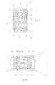
- FIG. 1is a perspective view of a tissue reinforcement prosthesis having a fastening region that accommodates the introduction of one or more fasteners.
- FIG. 2is a perspective view of a prosthesis system that includes the tissue reinforcement prosthesis shown in FIG. 1 and an auxiliary prosthesis that, in use, is telescopically anchored and supported by the tissue reinforcement prosthesis.
- FIG. 3is a perspective view of the tissue reinforcement prosthesis shown in FIG. 1 , showing the attachment of fasteners in the fastening region.
- FIG. 4is a perspective view of the tissue reinforcement prosthesis shown in FIG. 1 positioned within a hollow body organ by use of fasteners.
- FIG. 5Ais a perspective view of the tissue reinforcement prosthesis shown in FIG. 1 positioned within the proximal neck of an abdominal aortic aneurysm.
- FIG. 5Bis a perspective view of the tissue reinforcement prosthesis shown in FIG. 5A , with the inclusion of an optional supra-renal stent.
- FIG. 6Ais a perspective view of a prosthesis system that includes the tissue reinforcement prosthesis shown in FIG. 5A positioned within a proximal neck of the abdominal aortic aneurysm and an auxiliary prosthesis that is telescopically anchored and supported by the tissue reinforcement prosthesis and that bridges the aneurysm.
- FIG. 6Bis an enlarged view of the system shown in FIG. 6A , showing the telescopic fitment of the auxiliary prosthesis in the tissue reinforcement prosthesis.
- FIG. 6Cis an enlarged view of the system shown in FIG. 6A , showing a telescopic, interlocking fitment of the auxiliary prosthesis in the tissue reinforcement prosthesis.
- FIGS. 7, 8, and 9are perspective views of the deployment of the system shown in FIG. 6A by the sequential use of various intra-vascular catheters, one to deploy the tissue reinforcement prosthesis ( FIG. 7 ), another to apply fasteners to the tissue reinforcement prosthesis ( FIG. 8 ), and another to deploy the auxiliary prosthesis ( FIG. 9 ).
- FIG. 10is a perspective view of prosthesis positioned within an abdominal aortic aneurysm, the prosthesis having a fastening region that accommodates the introduction of one or more fasteners.
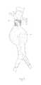
- FIG. 11is a perspective view of prosthesis positioned within an abdominal aortic aneurysm, the prosthesis having a tapered trunk located, at its proximal end, within the aorta and, at its distal end, in an iliac, the prosthesis also having a fastening region that accommodates the introduction of one or more fasteners.
- FIG. 1shows a tissue reinforcement prosthesis 10 that embodies features of the invention.
- the prosthesis 10serves to reinforce a region of a vessel wall or hollow body organ which has been weakened by disease or damage.
- the prosthesis 10desirable provides a platform on which to deploy a second prosthesis 36 (see FIG. 2 ) in the vessel or hollow body organ.
- the reinforcement prosthesis 10comprises a component part of an overall prosthesis system 52 .
- the prosthesis 10comprises a tubular trunk 12 .
- the trunk 12is sized and configured to fit within a targeted region of a hollow body organ and/or a blood vessel.
- the targeted regionis selected on the basis of certain anatomic characteristics. These characteristics include a weakened conditioned caused, e.g., by disease or damage.
- the trunk 12forms a generally cylindrical structure with an open interior lumen 18 .
- the trunk 12fortifies the body organ or blood vessel in the targeted region, to keep it from collapsing.
- the trunk 12includes a prosthetic material 14 supported by a scaffold 16 .
- the prosthetic material 14is selected on the basis of its biocompatibility, durability, and flexible mechanical properties.
- the material 14can comprise, e.g., woven polyester. Alternatively, a material comprising ePTFE can be used.
- the scaffold 16is desirable sized and configured to permit non-invasive deployment of the prosthesis 10 by an intra-vascular catheter.
- the scaffold 16is sized and configured to assume a compressed or collapsed, low profile condition, to permit its intra-vascular introduction into the hollow body organ and/or blood vessel by a catheter, as will be described in greater detail later.
- the scaffold 16is sized and configured for expansion in situ from its collapsed condition into an expanded condition in contact with tissue in the targeted region, as will also be described in greater detail later.
- the scaffold 16can comprise, e.g., a malleable plastic or metal material that expands in the presence of an applied force.
- the deployment cathetercan include, e.g., an expandable body, such as a balloon, to apply the expansion force to the scaffold 16 in situ.
- the scaffold 16can comprise a self-expanding plastic or metal material that can be compressed in the presence of a force, but self-expands upon removal of the compressive force.
- the deployment cathetercan include, e.g., a sleeve that can be manipulated to enclosed the scaffold 16 in a collapsed condition, thereby applying the compressive force, and to release the scaffold 16 when desired to allow the scaffold 16 to self-expand in situ.
- the scaffold 16can include individual self-expanding, zigzag type main stent rings 22 .
- the main stent rings 22can be made, e.g., from Nitinol® wire. Still, other materials, manufacturing methods and designs can be used.
- the main stent rings 22need not be attached to one another throughout the prosthesis material 14 .
- the individual main stent rings 22allow for longitudinal compliance while maintaining radial support of the open interior lumen 18 . This technical feature allows the prosthesis 10 to more readily accommodate changes in morphology in the targeted region. Still, it may be desirable in certain locations within the prosthesis structure to have attachments between the individual main stent rings 22 to provide enhanced stability and/or additional radial support.
- Each of the main stent rings 22can be, e.g., sewn onto prosthetic material 14 .
- the attachment of the main stent rings 22can be made, e.g., with polyester suture.
- attachment meanscould be utilized to secure the main stent rings 22 to the prosthetic material 14 .
- These meansinclude bonding; capturing the main stent rings 22 between two layers of prosthetic material 14 ; and incorporating the main stent rings 22 directly into the prosthetic material 14 .
- main stent rings 22In certain locations it is desired to have the main stent rings 22 attached to the outer diameter of the prosthetic material 14 . Still, it is also contemplated that the main stent rings 22 could be attached to the inner diameter of the prosthetic material 22 .
- At least one end of the trunk 12desirably also includes one or more end stent rings 24 .
- the principal purpose of an end stent ring 24is to provide a seal between the trunk 12 and adjoining tissue. This sealing function is particularly desirable when the prosthesis 10 is deployed in a blood vessel or other body organ, where body fluids are intended to reside or pass through the prosthesis 10 .
- the end sent rings 24can also serve, with the main stent rings 22 , to help maintain the position of the prosthesis 10 in the targeted region.
- the end stent rings 24desirably serve more of a sealing function than a retention function, the end stent rings 24 are desirably more compliant than the main stent rings 22 .
- the end stent rings 24also desirably occupy a minimum of area on the trunk 12 .
- the trunk 12(material 14 and/or scaffold 16 ) can carry radiopaque markers 46 to help fluoroscopically position the prosthesis 10 .
- the markers 46can take the form, e.g. of marker bands, tight wound coils, or wire made from radiopaque materials such as platinum, platinum/iridium, or gold.
- the trunk 12also desirably includes at least one fastening region 26 that accommodates the introduction of one or more fasteners 28 to anchor the prosthesis 10 in place (see FIG. 3 ). It is desirable that this region 26 of the trunk 12 be specially sized and configured for the receipt and retention of fasteners 28 .
- the size and spacing of ring stent patternscan be configured in the region 26 to specially accommodate the placement of fasteners; and/or woven fibers with an “X-pattern” or a “sinusoidal pattern” can be used in the region 26 to specially accommodate placement of fasteners; and/or the prosthetic material 14 can be folded-over to form multiple layers, to reinforce the prosthesis in the region 26 where fasteners are placed; and/or denser weave patterns or stronger fibers can be used, selected from, e.g., KevlarTM material or VectranTM material or metallic wire woven alone or interwoven with typical polyester fibers in the region 26 were fasteners are placed. It may also be desirable to fluoroscopically indicate this region 26 with auxiliary radiopaque markers 30 on the prosthetic material 14 , and/or auxiliary stent rings 32 to aid in positioning the fasteners.
- the fasteners 28can be variously constructed. They can, e.g., comprise helical fasteners or staples.
- the fasteners 28are introduced by an intra-vascular fastener attachment assembly. Details of a fastener attachment assembly that deploys helical fasteners can be found in U.S. patent application Ser. No. 10/307,226, filed Nov. 29, 2002, which is incorporated herein by reference.
- the targeted region for deployment of the tissue reinforcement prosthesis 10 as just describedcan vary.
- the targeted regioncan comprise a damaged or weakened area within a given body organ, as FIG. 4 shows.
- the presence of prosthesis 10provides reinforcement to the body organ where damage or weakness exists.
- the targeted regioncan comprise an aorta with an aneurysm.
- a tissue reinforcement prosthesis 10 in this targeted regioncould be indicated, e.g., when the neck proximal to the aneurysm (i.e., closest to the head) is either too short or otherwise has a native anatomic feature that interferes with the secure placement of a conventional endovascular prosthesis to bridge the aneurysm.
- the presence of prosthesis 10provides reinforcement to the proximal neck of the aneurysmal aorta adjacent the renal arteries.
- the reinforcement prosthesis 10can also serve to anchor and support an auxiliary prosthesis structure 36 that, in the absence of the reinforcement prosthesis 10 , could not be deployed, due to native anatomic features of the vessel.
- the auxiliary prosthesis structure 36comprises an endovascular graft that, when deployed, bridges the aneurysm. Together, the reinforcement prosthesis 10 and the graft 36 form a prosthesis system 52 , as shown in FIG. 6A .
- the graft 36includes a proximal end 38 that is sized and configured to be telescopically fitted within the lumen 18 of the trunk 12 .
- the lumen 18 of the trunk 12provides an interface region or socket 40 (see FIG. 6B ) that is fully enclosed within the body of the trunk 12 itself.
- the lumen 18is therefore not prone to kinking or twisting or other kinds of movement independent of the trunk 12 .
- the socket region 40 of the trunk 12be specially sized and configured for the receipt and retention of the auxiliary graft 36 , e.g., by the use of folded-over materials to form multiple layers, and/or the use of denser weave patters or stronger fibers from, e.g., KevlarTM material or VectranTM material or metallic wire woven alone or interwoven with typical polyester fibers in the socket region 40 , additional stent rings, and the like, to reinforce the prosthesis in the socket region 40 where hooks or barbs 60 of the graft 36 can obtain purchase; and/or by the use of radiopaque markers 42 to fluoroscopically identify the socket region 40 on the prosthetic material 14 ; and/or the use of auxiliary stent rings on the inside of the prosthetic material 14 in the socket region 40 that interfere with exterior stent rings on the graft 36 , to resist migration of graft 36 from the prosthesis 10 .
- the mechanical properties of the graft 36are supplemented by the reinforcement, support, and integrity of the socket region 40 and trunk 12 themselves, and vice versa. Coupled together, the trunk 12 and the graft 36 provide enhanced resistance to migration and/or separation of the graft 36 from the trunk 12 . Seated within the enclosed socket region 40 , the graft 36 is peripherally sealed within the trunk 12 to resist leaks or seepage of fluids around the graft 36 .
- a mechanically interlocking relationshipcan be established.
- a supplemental main stent ring 22 A on the interior of the socket region 40which would comprise the distal-most main stent ring of the trunk 12 —could be provided to mechanically engage or nest with a supplemental main stent ring 22 B on the exterior of the proximal end of the auxiliary prosthesis structure 36 .
- the mechanical interference between the supplemental stent rings 22 A and 22 Bserves to capture the auxiliary prosthesis structure 36 within the trunk 12 , preventing both distal and proximal migration between the two prostheses 10 and 36 .
- auxiliary prosthesis structure 36can be deployed first, and the prosthesis 10 deployed second to nest within an end of the auxiliary prosthesis structure 36 , thereby elongating and reinforcing the neck region.
- the trunk 12may include a supra-renal stent 44 at its proximal end, which extends beyond the prosthetic material 14 .
- this stent 44When deployed within the aorta, this stent 44 would extend above the level of the renal arteries.
- the supra-renal stent 44orients the prosthesis 10 within the lumen and aids in maintaining the position of the prosthesis 10 in the aorta without obstructing the normal blood flow into the renal arteries.
- a first catheter 20is navigated over a guide wire 48 through an iliac to the desired location within the aorta near the renal arteries.
- the catheter 20carries the reinforcement prosthesis 10 in a radially reduced configuration.
- the catheter 20releases the reinforcement prosthesis 10 , which expands radially into the position shown in FIG. 5A .
- the trunk 12 of the prosthesis 10desirable extends distally from the proximal neck and partially into the aneurysm sac.
- a fastener assembly 34is next deployed (see FIG. 8 ) to place fasteners 28 into the end region 28 of the trunk 12 .
- the prosthesis 10is thereby secured in position.
- the auxiliary graft 36is carried in a radially compressed condition by another over-the-wire catheter 50 (see FIG. 9 ).
- the catheter 50deploys the graft 36 , such that the proximal end of the graft 36 is telescopically received within the socket region 40 of the trunk 12 .
- the prosthesis system 52is thereby formed.
- any given tubular prosthesis 54can include a trunk 56 having a region 26 that is specially sized and configured for the receipt and retention of fasteners 28 , in the ways previously described.
- the trunk 56is sized and configured to extend, for purposes of illustration, in the aorta adjacent the renal arteries distally to a location proximal the natural bifurcation of the iliac arteries.
- the region 26is located in the neck of the aorta adjacent to the renal arteries. The features of the region 26 , previously described, make possible the secure attachment of the prosthesis 54 , without migration.
- the prosthesis 54desirable also includes other features of the prosthesis 10 already described, e.g., the main stent rings 22 , the end stent rings 24 , and the radiopaque markers 46 .
- the prosthesis 54can also include a supra-renal stent 44 of the type shown in FIG. 5B .
- the trunk 58 of a given prosthesis 56may be tapered, changing diameter from the proximal region to the distal region.
- the taperreduces the diameter of the trunk 58 in the proximal to distal direction. This taper direction is well suited for placement of the prosthesis 56 , at its proximal end, in the aorta adjacent the renal arteries and, at its distal end, in an iliac artery, as FIG. 11 shows.
- the trunk 58 of the prosthesis 56desirable also includes a region 26 that is specially sized and configured for the receipt and retention of fasteners 28 , in the ways previously described. As shown in FIG. 11 , the region 26 is located in the neck of the aorta adjacent to the renal arteries. The features of the region 26 , previously described, make possible the secure attachment of the prosthesis 56 , without migration.
- the prosthesis 56desirable also includes other features of the prosthesis 10 already described, e.g., the main stent rings 22 , the end stent rings 24 , and the radiopaque markers 46 .
- the prosthesis 54can also include a supra-renal stent 44 of the type shown in FIG. 5B .
- the targeted site of deploymentis within the aorta adjacent the renal arteries.
- this targeted site of deploymentis selected for purposes of illustrating the features of the prostheses 54 and 56 , and is not intended to be limiting.
Landscapes
- Health & Medical Sciences (AREA)
- Life Sciences & Earth Sciences (AREA)
- Surgery (AREA)
- General Health & Medical Sciences (AREA)
- Public Health (AREA)
- Biomedical Technology (AREA)
- Heart & Thoracic Surgery (AREA)
- Veterinary Medicine (AREA)
- Engineering & Computer Science (AREA)
- Animal Behavior & Ethology (AREA)
- Molecular Biology (AREA)
- Nuclear Medicine, Radiotherapy & Molecular Imaging (AREA)
- Medical Informatics (AREA)
- Gastroenterology & Hepatology (AREA)
- Pulmonology (AREA)
- Cardiology (AREA)
- Oral & Maxillofacial Surgery (AREA)
- Transplantation (AREA)
- Vascular Medicine (AREA)
- Prostheses (AREA)
- Media Introduction/Drainage Providing Device (AREA)
Abstract
Description
Claims (14)
Priority Applications (1)
| Application Number | Priority Date | Filing Date | Title |
|---|---|---|---|
| US11/981,112US9848869B2 (en) | 2001-11-28 | 2007-10-31 | Prosthesis systems and methods |
Applications Claiming Priority (6)
| Application Number | Priority Date | Filing Date | Title |
|---|---|---|---|
| US33393701P | 2001-11-28 | 2001-11-28 | |
| US10/271,334US6960217B2 (en) | 2001-11-28 | 2002-10-15 | Endovascular aneurysm repair system |
| US48901103P | 2003-07-21 | 2003-07-21 | |
| US10/693,255US6929661B2 (en) | 2001-11-28 | 2003-10-24 | Multi-lumen prosthesis systems and methods |
| US10/752,435US20050070992A1 (en) | 2001-11-28 | 2004-01-06 | Prosthesis systems and methods sized and configured for the receipt and retention of fasteners |
| US11/981,112US9848869B2 (en) | 2001-11-28 | 2007-10-31 | Prosthesis systems and methods |
Related Parent Applications (1)
| Application Number | Title | Priority Date | Filing Date |
|---|---|---|---|
| US10/752,435DivisionUS20050070992A1 (en) | 2001-11-28 | 2004-01-06 | Prosthesis systems and methods sized and configured for the receipt and retention of fasteners |
Publications (2)
| Publication Number | Publication Date |
|---|---|
| US20080065191A1 US20080065191A1 (en) | 2008-03-13 |
| US9848869B2true US9848869B2 (en) | 2017-12-26 |
Family
ID=34794698
Family Applications (2)
| Application Number | Title | Priority Date | Filing Date |
|---|---|---|---|
| US10/752,435AbandonedUS20050070992A1 (en) | 2001-11-28 | 2004-01-06 | Prosthesis systems and methods sized and configured for the receipt and retention of fasteners |
| US11/981,112Active2025-10-20US9848869B2 (en) | 2001-11-28 | 2007-10-31 | Prosthesis systems and methods |
Family Applications Before (1)
| Application Number | Title | Priority Date | Filing Date |
|---|---|---|---|
| US10/752,435AbandonedUS20050070992A1 (en) | 2001-11-28 | 2004-01-06 | Prosthesis systems and methods sized and configured for the receipt and retention of fasteners |
Country Status (7)
| Country | Link |
|---|---|
| US (2) | US20050070992A1 (en) |
| EP (1) | EP1708625A4 (en) |
| JP (2) | JP4284366B2 (en) |
| CN (1) | CN101151002A (en) |
| AU (1) | AU2005204615A1 (en) |
| CA (1) | CA2551685A1 (en) |
| WO (1) | WO2005067660A2 (en) |
Cited By (2)
| Publication number | Priority date | Publication date | Assignee | Title |
|---|---|---|---|---|
| US10888414B2 (en) | 2019-03-20 | 2021-01-12 | inQB8 Medical Technologies, LLC | Aortic dissection implant |
| US12097136B2 (en) | 2018-06-13 | 2024-09-24 | Endoron Medical Ltd. | Graft securing system, applicator and method |
Families Citing this family (41)
| Publication number | Priority date | Publication date | Assignee | Title |
|---|---|---|---|---|
| US7491232B2 (en) | 1998-09-18 | 2009-02-17 | Aptus Endosystems, Inc. | Catheter-based fastener implantation apparatus and methods with implantation force resolution |
| US20110087320A1 (en)* | 2001-11-28 | 2011-04-14 | Aptus Endosystems, Inc. | Devices, Systems, and Methods for Prosthesis Delivery and Implantation, Including a Prosthesis Assembly |
| AU2002353807B2 (en) | 2001-11-28 | 2008-08-14 | Aptus Endosystems, Inc. | Endovascular aneurysm repair system |
| US8231639B2 (en) | 2001-11-28 | 2012-07-31 | Aptus Endosystems, Inc. | Systems and methods for attaching a prosthesis within a body lumen or hollow organ |
| US9320503B2 (en) | 2001-11-28 | 2016-04-26 | Medtronic Vascular, Inc. | Devices, system, and methods for guiding an operative tool into an interior body region |
| US20070073389A1 (en)* | 2001-11-28 | 2007-03-29 | Aptus Endosystems, Inc. | Endovascular aneurysm devices, systems, and methods |
| US20090112303A1 (en)* | 2001-11-28 | 2009-04-30 | Lee Bolduc | Devices, systems, and methods for endovascular staple and/or prosthesis delivery and implantation |
| US20050070992A1 (en) | 2001-11-28 | 2005-03-31 | Aptus Endosystems, Inc. | Prosthesis systems and methods sized and configured for the receipt and retention of fasteners |
| US20050177180A1 (en)* | 2001-11-28 | 2005-08-11 | Aptus Endosystems, Inc. | Devices, systems, and methods for supporting tissue and/or structures within a hollow body organ |
| JP5523700B2 (en) | 2005-04-04 | 2014-06-18 | フレキシブル ステンティング ソリューションズ,インク. | Flexible stent |
| GB2427554B (en)* | 2005-06-23 | 2007-05-23 | Vascutek Ltd | Aneurysm graft with markers |
| WO2007016166A2 (en)* | 2005-07-27 | 2007-02-08 | Cook Critical Care Incorporated | Stent/graft device and method for open surgical placement |
| CN1911188B (en)* | 2005-08-09 | 2010-10-13 | 微创医疗器械(上海)有限公司 | Stent prosthesis used for surgical operation, and delivery device therefor |
| CN101466316B (en) | 2005-10-20 | 2012-06-27 | 阿普特斯内系统公司 | Devices systems and methods for prosthesis delivery and implantation including the use of a fastener tool |
| US20070239267A1 (en)* | 2006-03-28 | 2007-10-11 | Medtronic Vascular, Inc. | Stent Graft With Healing Promoting Necks |
| US20080085294A1 (en)* | 2006-10-04 | 2008-04-10 | Toby Freyman | Apparatuses and methods to treat atherosclerotic plaques |
| DE102006050385A1 (en)* | 2006-10-05 | 2008-04-10 | pfm Produkte für die Medizin AG | Implantable mechanism for use in human and/or animal body for e.g. closing atrium septum defect, has partial piece that is folded back on another partial piece from primary form into secondary form of carrying structure |
| US8388679B2 (en) | 2007-01-19 | 2013-03-05 | Maquet Cardiovascular Llc | Single continuous piece prosthetic tubular aortic conduit and method for manufacturing the same |
| DE102007019058A1 (en)* | 2007-04-23 | 2008-10-30 | Stengel, Max, Dr.Dr. | Vascular implant for the treatment of an aneurysm |
| US7988723B2 (en) | 2007-08-02 | 2011-08-02 | Flexible Stenting Solutions, Inc. | Flexible stent |
| US20090112237A1 (en)* | 2007-10-26 | 2009-04-30 | Cook Critical Care Incorporated | Vascular conduit and delivery system for open surgical placement |
| US9149376B2 (en) | 2008-10-06 | 2015-10-06 | Cordis Corporation | Reconstrainable stent delivery system |
| CA2740867C (en) | 2008-10-16 | 2018-06-12 | Aptus Endosystems, Inc. | Devices, systems, and methods for endovascular staple and/or prosthesis delivery and implantation |
| CN102100587B (en)* | 2009-12-18 | 2013-10-30 | 上海微创医疗器械(集团)有限公司 | Blood vessel bracket prosthesis |
| FR2962646B1 (en)* | 2010-07-16 | 2012-06-22 | Sofradim Production | PROSTHETIC WITH RADIO OPAQUE ELEMENT |
| US10265200B2 (en)* | 2010-08-10 | 2019-04-23 | Cook Medical Technologies Llc | Medical prostheses having bundled and non-bundled regions |
| US8903473B2 (en)* | 2010-09-15 | 2014-12-02 | Medtronic, Inc. | Radiopaque markers for implantable medical devices |
| US10321998B2 (en) | 2010-09-23 | 2019-06-18 | Transmural Systems Llc | Methods and systems for delivering prostheses using rail techniques |
| US9579193B2 (en) | 2010-09-23 | 2017-02-28 | Transmural Systems Llc | Methods and systems for delivering prostheses using rail techniques |
| US8696741B2 (en) | 2010-12-23 | 2014-04-15 | Maquet Cardiovascular Llc | Woven prosthesis and method for manufacturing the same |
| US9549817B2 (en) | 2011-09-22 | 2017-01-24 | Transmural Systems Llc | Devices, systems and methods for repairing lumenal systems |
| US9662196B2 (en) | 2011-09-27 | 2017-05-30 | Cook Medical Technologies Llc | Endoluminal prosthesis with steerable branch |
| US12053378B2 (en) | 2012-11-07 | 2024-08-06 | Transmural Systems Llc | Devices, systems and methods for repairing lumenal systems |
| EP3030201B1 (en)* | 2013-08-09 | 2017-06-28 | Boston Scientific Scimed, Inc. | Atraumatic stents including radiopaque connectors and methods |
| US20170014115A1 (en) | 2014-03-27 | 2017-01-19 | Transmural Systems Llc | Devices and methods for closure of transvascular or transcameral access ports |
| EP3349687B1 (en) | 2015-09-15 | 2020-09-09 | THE UNITED STATES OF AMERICA, represented by the S | Devices for effectuating percutaneous glenn and fontan procedures |
| CN105726164B (en)* | 2016-03-18 | 2018-01-23 | 杭州唯强医疗科技有限公司 | A plastic stent graft for aortic dissection and aortic dissection stent |
| CN106264782B (en)* | 2016-08-25 | 2019-04-26 | 北京天助瑞畅医疗技术有限公司 | Overlay film frame |
| JP7249332B2 (en) | 2017-09-01 | 2023-03-30 | トランスミューラル システムズ エルエルシー | Percutaneous shunt device and related methods |
| GB201806097D0 (en) | 2018-04-13 | 2018-05-30 | Heart Biotech Nano Ltd | Vascular graft |
| FR3126300B1 (en)* | 2021-08-31 | 2025-04-11 | Hospices Civils Lyon | Prosthesis for endo-bridging awaiting a future anastomosis |
Citations (107)
| Publication number | Priority date | Publication date | Assignee | Title |
|---|---|---|---|---|
| US2033039A (en) | 1935-05-22 | 1936-03-03 | Arthur A Limpert | Double point rotary pin |
| US3499222A (en) | 1965-08-17 | 1970-03-10 | Leonard I Linkow | Intra-osseous pins and posts and their use and techniques thereof |
| US3686740A (en) | 1970-06-19 | 1972-08-29 | Donald P Shiley | Method of assemblying a sutureless heart valve |
| US3799172A (en) | 1972-09-25 | 1974-03-26 | R Szpur | Retention catheter |
| US4140126A (en) | 1977-02-18 | 1979-02-20 | Choudhury M Hasan | Method for performing aneurysm repair |
| US4255820A (en) | 1979-07-24 | 1981-03-17 | Rothermel Joel E | Artificial ligaments |
| US4307722A (en) | 1979-08-14 | 1981-12-29 | Evans Joseph M | Dilators for arterial dilation |
| US4580568A (en) | 1984-10-01 | 1986-04-08 | Cook, Incorporated | Percutaneous endovascular stent and method for insertion thereof |
| US4586923A (en) | 1984-06-25 | 1986-05-06 | Cordis Corporation | Curving tip catheter |
| US4625597A (en) | 1983-09-16 | 1986-12-02 | Karl M. Reich Maschinenfabrik Gmbh | Screw driving apparatus |
| US4781682A (en) | 1987-08-13 | 1988-11-01 | Patel Piyush V | Catheter having support flaps and method of inserting catheter |
| EP0321912A1 (en) | 1987-12-18 | 1989-06-28 | Gerard L Delsanti | Removable endo-arterial devices intended to repair detachments in arterial walls |
| US4898577A (en) | 1988-09-28 | 1990-02-06 | Advanced Cardiovascular Systems, Inc. | Guiding cathether with controllable distal tip |
| US4921484A (en) | 1988-07-25 | 1990-05-01 | Cordis Corporation | Mesh balloon catheter device |
| US5030204A (en) | 1988-09-28 | 1991-07-09 | Advanced Cardiovascular Systems, Inc. | Guiding catheter with controllable distal tip |
| US5042707A (en) | 1990-10-16 | 1991-08-27 | Taheri Syde A | Intravascular stapler, and method of operating same |
| US5071407A (en) | 1990-04-12 | 1991-12-10 | Schneider (U.S.A.) Inc. | Radially expandable fixation member |
| US5104399A (en) | 1986-12-10 | 1992-04-14 | Endovascular Technologies, Inc. | Artificial graft and implantation method |
| US5199950A (en) | 1990-12-07 | 1993-04-06 | Willy Rusch Ag | Medical instrument |
| US5207695A (en) | 1989-06-19 | 1993-05-04 | Trout Iii Hugh H | Aortic graft, implantation device, and method for repairing aortic aneurysm |
| US5290295A (en) | 1992-07-15 | 1994-03-01 | Querals & Fine, Inc. | Insertion tool for an intraluminal graft procedure |
| US5320630A (en) | 1993-02-23 | 1994-06-14 | Munir Ahmed | Endoscopic ligating instrument for applying elastic bands |
| US5330503A (en) | 1989-05-16 | 1994-07-19 | Inbae Yoon | Spiral suture needle for joining tissue |
| US5330490A (en) | 1992-04-10 | 1994-07-19 | Wilk Peter J | Endoscopic device, prosthesis and method for use in endovascular repair |
| US5334196A (en) | 1992-10-05 | 1994-08-02 | United States Surgical Corporation | Endoscopic fastener remover |
| EP0663184A1 (en) | 1994-01-13 | 1995-07-19 | Ethicon Inc. | Spiral surgical tack |
| US5456714A (en) | 1991-07-04 | 1995-10-10 | Owen; Earl R. | Tubular surgical implant having a locking ring and flange |
| US5470337A (en) | 1994-05-17 | 1995-11-28 | Moss; Gerald | Surgical fastener |
| US5480382A (en) | 1989-01-09 | 1996-01-02 | Pilot Cardiovascular Systems, Inc. | Steerable medical device |
| US5489295A (en) | 1991-04-11 | 1996-02-06 | Endovascular Technologies, Inc. | Endovascular graft having bifurcation and apparatus and method for deploying the same |
| US5522881A (en) | 1994-06-28 | 1996-06-04 | Meadox Medicals, Inc. | Implantable tubular prosthesis having integral cuffs |
| US5562728A (en) | 1983-12-09 | 1996-10-08 | Endovascular Tech Inc | Endovascular grafting apparatus, system and method and devices for use therewith |
| US5571171A (en) | 1990-06-11 | 1996-11-05 | Barone; Hector D. | Method for repairing an artery in a body |
| US5571173A (en) | 1990-06-11 | 1996-11-05 | Parodi; Juan C. | Graft to repair a body passageway |
| US5582616A (en) | 1994-08-05 | 1996-12-10 | Origin Medsystems, Inc. | Surgical helical fastener with applicator |
| US5591195A (en) | 1995-10-30 | 1997-01-07 | Taheri; Syde | Apparatus and method for engrafting a blood vessel |
| WO1997003616A1 (en) | 1995-07-14 | 1997-02-06 | Spiros Skardoutsos | Angiosurgical device and vascular graft and vascular annulus for vessel-vascular graft binding |
| US5609627A (en) | 1994-02-09 | 1997-03-11 | Boston Scientific Technology, Inc. | Method for delivering a bifurcated endoluminal prosthesis |
| US5626613A (en) | 1995-05-04 | 1997-05-06 | Arthrex, Inc. | Corkscrew suture anchor and driver |
| US5639278A (en) | 1993-10-21 | 1997-06-17 | Corvita Corporation | Expandable supportive bifurcated endoluminal grafts |
| US5662683A (en) | 1995-08-22 | 1997-09-02 | Ortho Helix Limited | Open helical organic tissue anchor and method of facilitating healing |
| US5676696A (en) | 1995-02-24 | 1997-10-14 | Intervascular, Inc. | Modular bifurcated intraluminal grafts and methods for delivering and assembling same |
| US5676697A (en) | 1996-07-29 | 1997-10-14 | Cardiovascular Dynamics, Inc. | Two-piece, bifurcated intraluminal graft for repair of aneurysm |
| US5700269A (en) | 1995-06-06 | 1997-12-23 | Corvita Corporation | Endoluminal prosthesis deployment device for use with prostheses of variable length and having retraction ability |
| US5702365A (en) | 1992-09-08 | 1997-12-30 | King; Toby St. John | Daul-lumen catheter |
| US5713907A (en) | 1995-07-20 | 1998-02-03 | Endotex Interventional Systems, Inc. | Apparatus and method for dilating a lumen and for inserting an intraluminal graft |
| WO1998011814A2 (en) | 1996-09-20 | 1998-03-26 | United States Surgical Corporation | Coil fastener applier and remover |
| US5769884A (en)* | 1996-06-27 | 1998-06-23 | Cordis Corporation | Controlled porosity endovascular implant |
| US5779731A (en) | 1996-12-20 | 1998-07-14 | Cordis Corporation | Balloon catheter having dual markers and method |
| US5814016A (en) | 1991-07-16 | 1998-09-29 | Heartport, Inc. | Endovascular system for arresting the heart |
| US5824041A (en) | 1994-06-08 | 1998-10-20 | Medtronic, Inc. | Apparatus and methods for placement and repositioning of intraluminal prostheses |
| US5824037A (en) | 1995-10-03 | 1998-10-20 | Medtronic, Inc. | Modular intraluminal prostheses construction and methods |
| US5855565A (en) | 1997-02-21 | 1999-01-05 | Bar-Cohen; Yaniv | Cardiovascular mechanically expanding catheter |
| US5855598A (en) | 1993-10-21 | 1999-01-05 | Corvita Corporation | Expandable supportive branched endoluminal grafts |
| US5957940A (en) | 1997-06-30 | 1999-09-28 | Eva Corporation | Fasteners for use in the surgical repair of aneurysms |
| US5968053A (en) | 1997-01-31 | 1999-10-19 | Cardiac Assist Technologies, Inc. | Method and apparatus for implanting a graft in a vessel of a patient |
| US5972023A (en) | 1994-08-15 | 1999-10-26 | Eva Corporation | Implantation device for an aortic graft method of treating aortic aneurysm |
| US5972003A (en) | 1997-10-01 | 1999-10-26 | Sherwood Services Ag | Single-free ligation clip module |
| WO1999053845A1 (en) | 1998-04-20 | 1999-10-28 | St. Jude Medical, Inc. | Driver tool for heart valve prosthesis fasteners |
| US5980548A (en) | 1997-10-29 | 1999-11-09 | Kensey Nash Corporation | Transmyocardial revascularization system |
| US5993466A (en) | 1997-06-17 | 1999-11-30 | Yoon; Inbae | Suturing instrument with multiple rotatably mounted spreadable needle holders |
| US5993401A (en) | 1995-12-25 | 1999-11-30 | Matsushita Electric Works, Ltd. | Relax inducing device with heartbeat detection unit |
| WO2000016701A1 (en) | 1998-09-18 | 2000-03-30 | United States Surgical Corporation | Endovascular fastener applicator |
| US6070589A (en) | 1997-08-01 | 2000-06-06 | Teramed, Inc. | Methods for deploying bypass graft stents |
| US6086582A (en) | 1997-03-13 | 2000-07-11 | Altman; Peter A. | Cardiac drug delivery system |
| US6090137A (en) | 1993-04-26 | 2000-07-18 | Meadox Medicals, Inc. | Solid woven tubular prosthesis methods |
| US6145509A (en) | 1998-07-24 | 2000-11-14 | Eva Corporation | Depth sensor device for use in a surgical procedure |
| US6146339A (en) | 1999-05-24 | 2000-11-14 | Advanced Cardiovascular Systems | Guide wire with operator controllable tip stiffness |
| US6217597B1 (en) | 1998-07-24 | 2001-04-17 | Eva Corporation | Surgical cutting device and method of using the same |
| US6248118B1 (en) | 1997-06-30 | 2001-06-19 | Eva Corporation | Heat activated surgical fastener |
| US6258119B1 (en) | 1996-11-07 | 2001-07-10 | Myocardial Stents, Inc. | Implant device for trans myocardial revascularization |
| US6270516B1 (en) | 1997-06-30 | 2001-08-07 | Eva Corporation | Repair apparatus for use in surgical procedures |
| WO2001060432A1 (en) | 2000-02-15 | 2001-08-23 | Eva Corporation | Delivery catheter assembly and method of securing a surgical component to a vessel during a surgical procedure |
| US6287315B1 (en) | 1995-10-30 | 2001-09-11 | World Medical Manufacturing Corporation | Apparatus for delivering an endoluminal prosthesis |
| US6287335B1 (en) | 1999-04-26 | 2001-09-11 | William J. Drasler | Intravascular folded tubular endoprosthesis |
| US20010047199A1 (en)* | 1998-12-08 | 2001-11-29 | Bandula Wijay | Stent with nested or overlapping rings |
| US6336933B1 (en) | 1998-03-13 | 2002-01-08 | Juan C. Parodi | Endovascular device for application of prosthesis with sutures |
| US6371919B1 (en) | 1997-06-30 | 2002-04-16 | Eva Corporation | Method and apparatus for the surgical repair of aneurysms |
| US6398803B1 (en) | 1999-02-02 | 2002-06-04 | Impra, Inc., A Subsidiary Of C.R. Bard, Inc. | Partial encapsulation of stents |
| US6409757B1 (en) | 1999-09-15 | 2002-06-25 | Eva Corporation | Method and apparatus for supporting a graft assembly |
| US6416365B1 (en) | 1998-11-25 | 2002-07-09 | Yazaki Corporation | Connector containing front holder |
| US6428565B1 (en) | 1997-09-11 | 2002-08-06 | Medtronic Ave, Inc. | System and method for edoluminal grafting of bifurcated or branched vessels |
| US6458152B1 (en) | 1997-03-18 | 2002-10-01 | Endotex Interventional Systems, Inc. | Coiled sheet graft for single and bifurcated lumens and methods of making and use |
| US20020156521A1 (en) | 1995-12-01 | 2002-10-24 | Ryan Timothy J. | Bifurcated intraluminal prostheses construction and methods |
| US20020183827A1 (en) | 2001-06-01 | 2002-12-05 | American Medical Systems | Stent delivery device and method |
| US6520974B2 (en) | 1997-06-30 | 2003-02-18 | Eva Corporation | Surgical fastener |
| US6544253B1 (en) | 1998-07-24 | 2003-04-08 | Eva Corporation | Surgical support device and method of using the same |
| WO2003032870A1 (en) | 2001-10-17 | 2003-04-24 | Scimed Life Systems, Inc. | System for fixation of endoluminal devices |
| US20030100943A1 (en) | 2001-11-28 | 2003-05-29 | Lee Bolduc | Endovascular aneurysm repair system |
| WO2003079935A1 (en) | 2002-03-18 | 2003-10-02 | Eva Corporation | Method and apparatus to attach an unsupported surgical component |
| US6652572B2 (en) | 1998-10-05 | 2003-11-25 | Cordis Corporation | Endovascular graft system |
| WO2004008975A1 (en) | 2002-07-19 | 2004-01-29 | Olympus Corporation | Clip operation device |
| US6730119B1 (en) | 2000-10-06 | 2004-05-04 | Board Of Regents Of The University Of Texas System | Percutaneous implantation of partially covered stents in aneurysmally dilated arterial segments with subsequent embolization and obliteration of the aneurysm cavity |
| US20040138734A1 (en) | 2001-04-11 | 2004-07-15 | Trivascular, Inc. | Delivery system and method for bifurcated graft |
| US20040153143A1 (en) | 1991-04-11 | 2004-08-05 | Quiachon Dinah B. | Bifurcated multicapsule intraluminal grafting system and method |
| US20040254594A1 (en) | 2003-01-24 | 2004-12-16 | Arthur Alfaro | Cardiac defect occlusion device |
| US20050070992A1 (en) | 2001-11-28 | 2005-03-31 | Aptus Endosystems, Inc. | Prosthesis systems and methods sized and configured for the receipt and retention of fasteners |
| US20050154401A1 (en) | 2004-01-08 | 2005-07-14 | Scimed Life Systems, Inc. | Suturing device for implantable device |
| FR2865926A1 (en) | 2004-02-11 | 2005-08-12 | Perouse Laboratoires | Tubular prosthesis e.g. stent, for treating blood vessel e.g. vein, has three clamps regularly and angularly distributed at its periphery, where each clamp has two hooks movable between deployed and closure positions |
| US20050215874A1 (en) | 2004-03-12 | 2005-09-29 | Lixiao Wang | MRI and X-ray visualization |
| US20060111692A1 (en) | 2004-07-19 | 2006-05-25 | Hlavka Edwin J | Robotically controlled intravascular tissue injection system |
| US20060253186A1 (en) | 2005-05-09 | 2006-11-09 | Paragon Intellectual Properties, Llc | Apparatus and methods for renal stenting |
| US20080097489A1 (en) | 1999-04-09 | 2008-04-24 | Evalve, Inc. | Fixation devices, systems and methods for engaging tissue |
| US8685044B2 (en) | 2001-11-28 | 2014-04-01 | Aptus Endosystems, Inc. | Systems and methods for attaching a prosthesis with a body lumen or hollow organ |
| US8690897B2 (en) | 2001-11-28 | 2014-04-08 | Aptus Endosystems, Inc. | Devices, systems, and methods for prosthesis delivery and implantation, including the use of a fastener tool |
| AU2011224089B2 (en) | 2004-02-25 | 2014-04-17 | Aptus Endosystems, Inc. | Systems and methods for attaching a prosthesis within a body lumen or hollow organ |
| US20150127015A1 (en) | 2001-11-28 | 2015-05-07 | Aptus Endosystems, Inc. | Endovascular aneurysm devices, systems, and methods |
Family Cites Families (7)
| Publication number | Priority date | Publication date | Assignee | Title |
|---|---|---|---|---|
| JP3577353B2 (en)* | 1995-01-27 | 2004-10-13 | テルモ株式会社 | In-vivo stent |
| US5662613A (en)* | 1996-05-14 | 1997-09-02 | Astarita; Denis C. | Endoscopic instrument lock |
| US6086583A (en)* | 1997-06-05 | 2000-07-11 | Asahi Kogaku Kogyo Kabushiki Kaisha | Electric cautery for endoscope |
| ES2227877T3 (en)* | 1997-12-16 | 2005-04-01 | B. Braun Celsa | MEDICAL SET FOR THE TREATMENT OF AN ANATOMICAL CONDUCT AFFECTION. |
| WO1999030637A1 (en)* | 1997-12-16 | 1999-06-24 | B. Braun Celsa | Medical treatment of a diseased anatomical duct |
| US6361556B1 (en)* | 2000-04-27 | 2002-03-26 | Endovascular Tech Inc | System and method for endovascular aneurysm repair in conjuction with vascular stabilization |
| US20030204249A1 (en)* | 2002-04-25 | 2003-10-30 | Michel Letort | Endovascular stent graft and fixation cuff |
- 2004
- 2004-01-06USUS10/752,435patent/US20050070992A1/ennot_activeAbandoned
- 2005
- 2005-01-03CNCNA2005800020269Apatent/CN101151002A/enactivePending
- 2005-01-03JPJP2006547608Apatent/JP4284366B2/ennot_activeExpired - Fee Related
- 2005-01-03CACA002551685Apatent/CA2551685A1/ennot_activeAbandoned
- 2005-01-03EPEP05704902Apatent/EP1708625A4/ennot_activeWithdrawn
- 2005-01-03WOPCT/US2005/000059patent/WO2005067660A2/enactiveApplication Filing
- 2005-01-03AUAU2005204615Apatent/AU2005204615A1/ennot_activeAbandoned
- 2007
- 2007-10-31USUS11/981,112patent/US9848869B2/enactiveActive
- 2008
- 2008-12-19JPJP2008323278Apatent/JP2009095684A/enactivePending
Patent Citations (122)
| Publication number | Priority date | Publication date | Assignee | Title |
|---|---|---|---|---|
| US2033039A (en) | 1935-05-22 | 1936-03-03 | Arthur A Limpert | Double point rotary pin |
| US3499222A (en) | 1965-08-17 | 1970-03-10 | Leonard I Linkow | Intra-osseous pins and posts and their use and techniques thereof |
| US3686740A (en) | 1970-06-19 | 1972-08-29 | Donald P Shiley | Method of assemblying a sutureless heart valve |
| US3799172A (en) | 1972-09-25 | 1974-03-26 | R Szpur | Retention catheter |
| US4140126A (en) | 1977-02-18 | 1979-02-20 | Choudhury M Hasan | Method for performing aneurysm repair |
| US4255820A (en) | 1979-07-24 | 1981-03-17 | Rothermel Joel E | Artificial ligaments |
| US4307722A (en) | 1979-08-14 | 1981-12-29 | Evans Joseph M | Dilators for arterial dilation |
| US4625597A (en) | 1983-09-16 | 1986-12-02 | Karl M. Reich Maschinenfabrik Gmbh | Screw driving apparatus |
| US5562728A (en) | 1983-12-09 | 1996-10-08 | Endovascular Tech Inc | Endovascular grafting apparatus, system and method and devices for use therewith |
| US5662700A (en) | 1983-12-09 | 1997-09-02 | Endovascular Technologies, Inc. | Artificial graft and implantation method |
| US4586923A (en) | 1984-06-25 | 1986-05-06 | Cordis Corporation | Curving tip catheter |
| US4580568A (en) | 1984-10-01 | 1986-04-08 | Cook, Incorporated | Percutaneous endovascular stent and method for insertion thereof |
| US5104399A (en) | 1986-12-10 | 1992-04-14 | Endovascular Technologies, Inc. | Artificial graft and implantation method |
| US4781682A (en) | 1987-08-13 | 1988-11-01 | Patel Piyush V | Catheter having support flaps and method of inserting catheter |
| EP0321912A1 (en) | 1987-12-18 | 1989-06-28 | Gerard L Delsanti | Removable endo-arterial devices intended to repair detachments in arterial walls |
| US4921484A (en) | 1988-07-25 | 1990-05-01 | Cordis Corporation | Mesh balloon catheter device |
| US5030204A (en) | 1988-09-28 | 1991-07-09 | Advanced Cardiovascular Systems, Inc. | Guiding catheter with controllable distal tip |
| US4898577A (en) | 1988-09-28 | 1990-02-06 | Advanced Cardiovascular Systems, Inc. | Guiding cathether with controllable distal tip |
| US5480382A (en) | 1989-01-09 | 1996-01-02 | Pilot Cardiovascular Systems, Inc. | Steerable medical device |
| US5330503A (en) | 1989-05-16 | 1994-07-19 | Inbae Yoon | Spiral suture needle for joining tissue |
| US5207695A (en) | 1989-06-19 | 1993-05-04 | Trout Iii Hugh H | Aortic graft, implantation device, and method for repairing aortic aneurysm |
| US5071407A (en) | 1990-04-12 | 1991-12-10 | Schneider (U.S.A.) Inc. | Radially expandable fixation member |
| US5571171A (en) | 1990-06-11 | 1996-11-05 | Barone; Hector D. | Method for repairing an artery in a body |
| US5571173A (en) | 1990-06-11 | 1996-11-05 | Parodi; Juan C. | Graft to repair a body passageway |
| US5042707A (en) | 1990-10-16 | 1991-08-27 | Taheri Syde A | Intravascular stapler, and method of operating same |
| US5199950A (en) | 1990-12-07 | 1993-04-06 | Willy Rusch Ag | Medical instrument |
| US5489295A (en) | 1991-04-11 | 1996-02-06 | Endovascular Technologies, Inc. | Endovascular graft having bifurcation and apparatus and method for deploying the same |
| US20040153143A1 (en) | 1991-04-11 | 2004-08-05 | Quiachon Dinah B. | Bifurcated multicapsule intraluminal grafting system and method |
| US5456714A (en) | 1991-07-04 | 1995-10-10 | Owen; Earl R. | Tubular surgical implant having a locking ring and flange |
| US5814016A (en) | 1991-07-16 | 1998-09-29 | Heartport, Inc. | Endovascular system for arresting the heart |
| US5330490A (en) | 1992-04-10 | 1994-07-19 | Wilk Peter J | Endoscopic device, prosthesis and method for use in endovascular repair |
| US5290295A (en) | 1992-07-15 | 1994-03-01 | Querals & Fine, Inc. | Insertion tool for an intraluminal graft procedure |
| US5702365A (en) | 1992-09-08 | 1997-12-30 | King; Toby St. John | Daul-lumen catheter |
| US5334196A (en) | 1992-10-05 | 1994-08-02 | United States Surgical Corporation | Endoscopic fastener remover |
| US5320630A (en) | 1993-02-23 | 1994-06-14 | Munir Ahmed | Endoscopic ligating instrument for applying elastic bands |
| US6090137A (en) | 1993-04-26 | 2000-07-18 | Meadox Medicals, Inc. | Solid woven tubular prosthesis methods |
| US5855598A (en) | 1993-10-21 | 1999-01-05 | Corvita Corporation | Expandable supportive branched endoluminal grafts |
| US5639278A (en) | 1993-10-21 | 1997-06-17 | Corvita Corporation | Expandable supportive bifurcated endoluminal grafts |
| EP0663184A1 (en) | 1994-01-13 | 1995-07-19 | Ethicon Inc. | Spiral surgical tack |
| US6302906B1 (en) | 1994-02-09 | 2001-10-16 | Boston Scientific Technology, Inc. | System for delivering a prosthesis |
| US5609627A (en) | 1994-02-09 | 1997-03-11 | Boston Scientific Technology, Inc. | Method for delivering a bifurcated endoluminal prosthesis |
| US5470337A (en) | 1994-05-17 | 1995-11-28 | Moss; Gerald | Surgical fastener |
| US5824041A (en) | 1994-06-08 | 1998-10-20 | Medtronic, Inc. | Apparatus and methods for placement and repositioning of intraluminal prostheses |
| US6126685A (en) | 1994-06-08 | 2000-10-03 | Medtronic, Inc. | Apparatus and methods for placement and repositioning of intraluminal prostheses |
| US5522881A (en) | 1994-06-28 | 1996-06-04 | Meadox Medicals, Inc. | Implantable tubular prosthesis having integral cuffs |
| US5582616A (en) | 1994-08-05 | 1996-12-10 | Origin Medsystems, Inc. | Surgical helical fastener with applicator |
| US6296656B1 (en) | 1994-08-05 | 2001-10-02 | Origin Medsystems, Inc. | Surgical helical fastener with applicator |
| US5810882A (en) | 1994-08-05 | 1998-09-22 | Origin Medsystems, Inc. | Surgical helical fastener with applicator and method of use |
| US5964772A (en) | 1994-08-05 | 1999-10-12 | Origin Medsystems, Inc. | Applicator for attaching fasteners to tissue |
| US6562051B1 (en) | 1994-08-05 | 2003-05-13 | Sherwood Services Ag | Surgical helical fastener with applicator |
| US5824008A (en) | 1994-08-05 | 1998-10-20 | Origin Medsystems, Inc. | System for applying fasteners to tissue |
| US5972023A (en) | 1994-08-15 | 1999-10-26 | Eva Corporation | Implantation device for an aortic graft method of treating aortic aneurysm |
| US5676696A (en) | 1995-02-24 | 1997-10-14 | Intervascular, Inc. | Modular bifurcated intraluminal grafts and methods for delivering and assembling same |
| US5626613A (en) | 1995-05-04 | 1997-05-06 | Arthrex, Inc. | Corkscrew suture anchor and driver |
| US5700269A (en) | 1995-06-06 | 1997-12-23 | Corvita Corporation | Endoluminal prosthesis deployment device for use with prostheses of variable length and having retraction ability |
| WO1997003616A1 (en) | 1995-07-14 | 1997-02-06 | Spiros Skardoutsos | Angiosurgical device and vascular graft and vascular annulus for vessel-vascular graft binding |
| US5713907A (en) | 1995-07-20 | 1998-02-03 | Endotex Interventional Systems, Inc. | Apparatus and method for dilating a lumen and for inserting an intraluminal graft |
| US5662683A (en) | 1995-08-22 | 1997-09-02 | Ortho Helix Limited | Open helical organic tissue anchor and method of facilitating healing |
| US5824037A (en) | 1995-10-03 | 1998-10-20 | Medtronic, Inc. | Modular intraluminal prostheses construction and methods |
| US5591195A (en) | 1995-10-30 | 1997-01-07 | Taheri; Syde | Apparatus and method for engrafting a blood vessel |
| US6287315B1 (en) | 1995-10-30 | 2001-09-11 | World Medical Manufacturing Corporation | Apparatus for delivering an endoluminal prosthesis |
| US20020156521A1 (en) | 1995-12-01 | 2002-10-24 | Ryan Timothy J. | Bifurcated intraluminal prostheses construction and methods |
| US5993401A (en) | 1995-12-25 | 1999-11-30 | Matsushita Electric Works, Ltd. | Relax inducing device with heartbeat detection unit |
| US5769884A (en)* | 1996-06-27 | 1998-06-23 | Cordis Corporation | Controlled porosity endovascular implant |
| US5676697A (en) | 1996-07-29 | 1997-10-14 | Cardiovascular Dynamics, Inc. | Two-piece, bifurcated intraluminal graft for repair of aneurysm |
| WO1998011814A2 (en) | 1996-09-20 | 1998-03-26 | United States Surgical Corporation | Coil fastener applier and remover |
| US6258119B1 (en) | 1996-11-07 | 2001-07-10 | Myocardial Stents, Inc. | Implant device for trans myocardial revascularization |
| US5779731A (en) | 1996-12-20 | 1998-07-14 | Cordis Corporation | Balloon catheter having dual markers and method |
| US5968053A (en) | 1997-01-31 | 1999-10-19 | Cardiac Assist Technologies, Inc. | Method and apparatus for implanting a graft in a vessel of a patient |
| US5855565A (en) | 1997-02-21 | 1999-01-05 | Bar-Cohen; Yaniv | Cardiovascular mechanically expanding catheter |
| US6086582A (en) | 1997-03-13 | 2000-07-11 | Altman; Peter A. | Cardiac drug delivery system |
| US6458152B1 (en) | 1997-03-18 | 2002-10-01 | Endotex Interventional Systems, Inc. | Coiled sheet graft for single and bifurcated lumens and methods of making and use |
| US5993466A (en) | 1997-06-17 | 1999-11-30 | Yoon; Inbae | Suturing instrument with multiple rotatably mounted spreadable needle holders |
| US6520974B2 (en) | 1997-06-30 | 2003-02-18 | Eva Corporation | Surgical fastener |
| US6248118B1 (en) | 1997-06-30 | 2001-06-19 | Eva Corporation | Heat activated surgical fastener |
| US6371919B1 (en) | 1997-06-30 | 2002-04-16 | Eva Corporation | Method and apparatus for the surgical repair of aneurysms |
| US6270516B1 (en) | 1997-06-30 | 2001-08-07 | Eva Corporation | Repair apparatus for use in surgical procedures |
| US5957940A (en) | 1997-06-30 | 1999-09-28 | Eva Corporation | Fasteners for use in the surgical repair of aneurysms |
| US6070589A (en) | 1997-08-01 | 2000-06-06 | Teramed, Inc. | Methods for deploying bypass graft stents |
| US6428565B1 (en) | 1997-09-11 | 2002-08-06 | Medtronic Ave, Inc. | System and method for edoluminal grafting of bifurcated or branched vessels |
| US5972003A (en) | 1997-10-01 | 1999-10-26 | Sherwood Services Ag | Single-free ligation clip module |
| US5980548A (en) | 1997-10-29 | 1999-11-09 | Kensey Nash Corporation | Transmyocardial revascularization system |
| US6336933B1 (en) | 1998-03-13 | 2002-01-08 | Juan C. Parodi | Endovascular device for application of prosthesis with sutures |
| WO1999053845A1 (en) | 1998-04-20 | 1999-10-28 | St. Jude Medical, Inc. | Driver tool for heart valve prosthesis fasteners |
| US6544253B1 (en) | 1998-07-24 | 2003-04-08 | Eva Corporation | Surgical support device and method of using the same |
| US6217597B1 (en) | 1998-07-24 | 2001-04-17 | Eva Corporation | Surgical cutting device and method of using the same |
| US6145509A (en) | 1998-07-24 | 2000-11-14 | Eva Corporation | Depth sensor device for use in a surgical procedure |
| WO2000016701A1 (en) | 1998-09-18 | 2000-03-30 | United States Surgical Corporation | Endovascular fastener applicator |
| US6800081B2 (en) | 1998-09-18 | 2004-10-05 | Aptus Endosystems, Inc. | Systems and methods for applying a suture within a blood vesel lumen |
| US6592593B1 (en) | 1998-09-18 | 2003-07-15 | United States Surgical Corporation | Endovascular fastener applicator |
| US6652572B2 (en) | 1998-10-05 | 2003-11-25 | Cordis Corporation | Endovascular graft system |
| US6416365B1 (en) | 1998-11-25 | 2002-07-09 | Yazaki Corporation | Connector containing front holder |
| US20010047199A1 (en)* | 1998-12-08 | 2001-11-29 | Bandula Wijay | Stent with nested or overlapping rings |
| US6398803B1 (en) | 1999-02-02 | 2002-06-04 | Impra, Inc., A Subsidiary Of C.R. Bard, Inc. | Partial encapsulation of stents |
| US20080097489A1 (en) | 1999-04-09 | 2008-04-24 | Evalve, Inc. | Fixation devices, systems and methods for engaging tissue |
| US6287335B1 (en) | 1999-04-26 | 2001-09-11 | William J. Drasler | Intravascular folded tubular endoprosthesis |
| US6146339A (en) | 1999-05-24 | 2000-11-14 | Advanced Cardiovascular Systems | Guide wire with operator controllable tip stiffness |
| US6409757B1 (en) | 1999-09-15 | 2002-06-25 | Eva Corporation | Method and apparatus for supporting a graft assembly |
| WO2001060432A1 (en) | 2000-02-15 | 2001-08-23 | Eva Corporation | Delivery catheter assembly and method of securing a surgical component to a vessel during a surgical procedure |
| US6730119B1 (en) | 2000-10-06 | 2004-05-04 | Board Of Regents Of The University Of Texas System | Percutaneous implantation of partially covered stents in aneurysmally dilated arterial segments with subsequent embolization and obliteration of the aneurysm cavity |
| US20040138734A1 (en) | 2001-04-11 | 2004-07-15 | Trivascular, Inc. | Delivery system and method for bifurcated graft |
| US20020183827A1 (en) | 2001-06-01 | 2002-12-05 | American Medical Systems | Stent delivery device and method |
| WO2003032870A1 (en) | 2001-10-17 | 2003-04-24 | Scimed Life Systems, Inc. | System for fixation of endoluminal devices |
| US20030100943A1 (en) | 2001-11-28 | 2003-05-29 | Lee Bolduc | Endovascular aneurysm repair system |
| US8685044B2 (en) | 2001-11-28 | 2014-04-01 | Aptus Endosystems, Inc. | Systems and methods for attaching a prosthesis with a body lumen or hollow organ |
| WO2003045467A2 (en) | 2001-11-28 | 2003-06-05 | Aptus Endosystems, Inc. | Intraluminal prosthesis attachment systems and methods |
| US20150127015A1 (en) | 2001-11-28 | 2015-05-07 | Aptus Endosystems, Inc. | Endovascular aneurysm devices, systems, and methods |
| US20050070992A1 (en) | 2001-11-28 | 2005-03-31 | Aptus Endosystems, Inc. | Prosthesis systems and methods sized and configured for the receipt and retention of fasteners |
| US20140214051A1 (en) | 2001-11-28 | 2014-07-31 | Aptus Endosystems, Inc. | Devices, systems, and methods for prosthesis delivery and implantation, including the use of a fastener tool |
| US20140194902A1 (en) | 2001-11-28 | 2014-07-10 | Aptus Endosystems, Inc. | Systems and methods for attaching a prosthesis within a body lumen or hollow organ |
| US8690897B2 (en) | 2001-11-28 | 2014-04-08 | Aptus Endosystems, Inc. | Devices, systems, and methods for prosthesis delivery and implantation, including the use of a fastener tool |
| WO2003079935A1 (en) | 2002-03-18 | 2003-10-02 | Eva Corporation | Method and apparatus to attach an unsupported surgical component |
| WO2004008975A1 (en) | 2002-07-19 | 2004-01-29 | Olympus Corporation | Clip operation device |
| US20040254594A1 (en) | 2003-01-24 | 2004-12-16 | Arthur Alfaro | Cardiac defect occlusion device |
| WO2005067660A2 (en) | 2004-01-06 | 2005-07-28 | Aptus Endosystems, Inc. | Prosthesis systems and methods sized and configured for the receipt and retention of fasteners |
| WO2005067660A3 (en) | 2004-01-06 | 2007-04-05 | Aptus Endosystems Inc | Prosthesis systems and methods sized and configured for the receipt and retention of fasteners |
| US20050154401A1 (en) | 2004-01-08 | 2005-07-14 | Scimed Life Systems, Inc. | Suturing device for implantable device |
| FR2865926A1 (en) | 2004-02-11 | 2005-08-12 | Perouse Laboratoires | Tubular prosthesis e.g. stent, for treating blood vessel e.g. vein, has three clamps regularly and angularly distributed at its periphery, where each clamp has two hooks movable between deployed and closure positions |
| AU2011224089B2 (en) | 2004-02-25 | 2014-04-17 | Aptus Endosystems, Inc. | Systems and methods for attaching a prosthesis within a body lumen or hollow organ |
| US20050215874A1 (en) | 2004-03-12 | 2005-09-29 | Lixiao Wang | MRI and X-ray visualization |
| US20060111692A1 (en) | 2004-07-19 | 2006-05-25 | Hlavka Edwin J | Robotically controlled intravascular tissue injection system |
| US20060253186A1 (en) | 2005-05-09 | 2006-11-09 | Paragon Intellectual Properties, Llc | Apparatus and methods for renal stenting |
Non-Patent Citations (68)
Cited By (3)
| Publication number | Priority date | Publication date | Assignee | Title |
|---|---|---|---|---|
| US12097136B2 (en) | 2018-06-13 | 2024-09-24 | Endoron Medical Ltd. | Graft securing system, applicator and method |
| US12295868B2 (en) | 2018-06-13 | 2025-05-13 | Endoron Medical Ltd. | Graft securing system, applicator and method |
| US10888414B2 (en) | 2019-03-20 | 2021-01-12 | inQB8 Medical Technologies, LLC | Aortic dissection implant |
Also Published As
| Publication number | Publication date |
|---|---|
| EP1708625A4 (en) | 2011-09-28 |
| JP4284366B2 (en) | 2009-06-24 |
| US20050070992A1 (en) | 2005-03-31 |
| WO2005067660A2 (en) | 2005-07-28 |
| US20080065191A1 (en) | 2008-03-13 |
| EP1708625A2 (en) | 2006-10-11 |
| AU2005204615A1 (en) | 2005-07-28 |
| CN101151002A (en) | 2008-03-26 |
| JP2007523694A (en) | 2007-08-23 |
| JP2009095684A (en) | 2009-05-07 |
| CA2551685A1 (en) | 2005-07-28 |
| WO2005067660A3 (en) | 2007-04-05 |
Similar Documents
| Publication | Publication Date | Title |
|---|---|---|
| US9848869B2 (en) | Prosthesis systems and methods | |
| CA2610703C (en) | Side branch stent graft | |
| AU2004287355B2 (en) | Multi-lumen prosthesis systems and methods | |
| US9095461B2 (en) | Aorta and branch vessel stent grafts and method | |
| US7131991B2 (en) | Endoluminal prosthetic assembly and extension method | |
| US7232459B2 (en) | Thoracic aortic aneurysm stent graft | |
| US6669720B1 (en) | Prosthesis for endovascular repair of abdominal aortic aneurysms |
Legal Events
| Date | Code | Title | Description |
|---|---|---|---|
| AS | Assignment | Owner name:COMERICA BANK,MICHIGAN Free format text:SECURITY AGREEMENT;ASSIGNOR:APTUS ENDOSYSTEMS, INC.;REEL/FRAME:023882/0119 Effective date:20100129 Owner name:COMERICA BANK, MICHIGAN Free format text:SECURITY AGREEMENT;ASSIGNOR:APTUS ENDOSYSTEMS, INC.;REEL/FRAME:023882/0119 Effective date:20100129 | |
| AS | Assignment | Owner name:APTUS ENDOSYSTEMS, INC., CALIFORNIA Free format text:ASSIGNMENT OF ASSIGNORS INTEREST;ASSIGNORS:BOLDUC, LEE;PARODI, JUAN;SIGNING DATES FROM 20040419 TO 20040426;REEL/FRAME:025490/0365 | |
| AS | Assignment | Owner name:APTUS ENDOSYSTEMS, INC., CALIFORNIA Free format text:RELEASE BY SECURED PARTY;ASSIGNOR:COMERICA BANK;REEL/FRAME:028893/0426 Effective date:20120831 | |
| AS | Assignment | Owner name:MEDTRONIC VASCULAR, INC., MINNESOTA Free format text:ASSIGNMENT OF ASSIGNORS INTEREST;ASSIGNOR:APTUS ENDOSYSTEMS, INC.;REEL/FRAME:036127/0486 Effective date:20150619 | |
| STCF | Information on status: patent grant | Free format text:PATENTED CASE | |
| MAFP | Maintenance fee payment | Free format text:PAYMENT OF MAINTENANCE FEE, 4TH YEAR, LARGE ENTITY (ORIGINAL EVENT CODE: M1551); ENTITY STATUS OF PATENT OWNER: LARGE ENTITY Year of fee payment:4 | |
| FEPP | Fee payment procedure | Free format text:MAINTENANCE FEE REMINDER MAILED (ORIGINAL EVENT CODE: REM.); ENTITY STATUS OF PATENT OWNER: LARGE ENTITY |