US9848715B2 - Rocker - Google Patents
RockerDownload PDFInfo
- Publication number
- US9848715B2 US9848715B2US14/327,871US201414327871AUS9848715B2US 9848715 B2US9848715 B2US 9848715B2US 201414327871 AUS201414327871 AUS 201414327871AUS 9848715 B2US9848715 B2US 9848715B2
- Authority
- US
- United States
- Prior art keywords
- rocker
- frame
- seat
- frame portion
- legs
- Prior art date
- Legal status (The legal status is an assumption and is not a legal conclusion. Google has not performed a legal analysis and makes no representation as to the accuracy of the status listed.)
- Active, expires
Links
Images


Classifications
- A—HUMAN NECESSITIES
- A47—FURNITURE; DOMESTIC ARTICLES OR APPLIANCES; COFFEE MILLS; SPICE MILLS; SUCTION CLEANERS IN GENERAL
- A47D—FURNITURE SPECIALLY ADAPTED FOR CHILDREN
- A47D13/00—Other nursery furniture
- A47D13/10—Rocking-chairs; Indoor Swings ; Baby bouncers
- A47D13/102—Rocking-chairs; Indoor Swings ; Baby bouncers with curved rocking members resting on the ground
- A—HUMAN NECESSITIES
- A47—FURNITURE; DOMESTIC ARTICLES OR APPLIANCES; COFFEE MILLS; SPICE MILLS; SUCTION CLEANERS IN GENERAL
- A47C—CHAIRS; SOFAS; BEDS
- A47C7/00—Parts, details, or accessories of chairs or stools
- A47C7/62—Accessories for chairs
- A47C7/72—Adaptations for incorporating lamps, radio sets, bars, telephones, ventilation, heating or cooling arrangements or the like
- A47C7/727—Adaptations for incorporating lamps, radio sets, bars, telephones, ventilation, heating or cooling arrangements or the like with speakers
- A—HUMAN NECESSITIES
- A47—FURNITURE; DOMESTIC ARTICLES OR APPLIANCES; COFFEE MILLS; SPICE MILLS; SUCTION CLEANERS IN GENERAL
- A47D—FURNITURE SPECIALLY ADAPTED FOR CHILDREN
- A47D1/00—Children's chairs
- A47D1/002—Children's chairs adjustable
- A47D1/004—Children's chairs adjustable in height
- A—HUMAN NECESSITIES
- A47—FURNITURE; DOMESTIC ARTICLES OR APPLIANCES; COFFEE MILLS; SPICE MILLS; SUCTION CLEANERS IN GENERAL
- A47D—FURNITURE SPECIALLY ADAPTED FOR CHILDREN
- A47D1/00—Children's chairs
- A47D1/02—Foldable chairs
- A—HUMAN NECESSITIES
- A47—FURNITURE; DOMESTIC ARTICLES OR APPLIANCES; COFFEE MILLS; SPICE MILLS; SUCTION CLEANERS IN GENERAL
- A47D—FURNITURE SPECIALLY ADAPTED FOR CHILDREN
- A47D13/00—Other nursery furniture
- A47D13/10—Rocking-chairs; Indoor Swings ; Baby bouncers
- A47D13/101—Foldable rocking chairs
Definitions
- the present inventionrelates generally to the field of accessories and support devices for children and infants, and more particularly to rocking child seats, rockers, bassinets, inclined sleeping apparatuses, and the like.
- the present inventionprovides a rocker or similar motion device for infants and children including a child receiving receptacle and a collapsible frame assembly attached to and supporting the child receiving receptacle.
- the present inventionrelates to a rocker including a frame having a first and a second frame portion and a seat coupled to at least one of the frame portions of the frame.
- the first and second frame portionseach include two legs and an arcuate or radiused lower base portion connecting the two legs together.
- first and second frame portionsare pivotally connected together proximal the respective legs thereof such that one of the frame portions can pivot relative to the other fame portion between an expanded configuration and a collapsed configuration, and wherein the arcuate or radiused lower base portions of the at least two frame portions are configured to rock on a support surface in the expanded configuration.
- the radiused portions of the first and second frame portionsare generally arcuate and configured to rock on the support surface in a side-to-side motion.
- the motion deviceis configured to receive an infant within the seat such that the infant's body is generally oriented in a front-to-back orientation (longitudinally or axially), and wherein the first and second frame portions are configured to rock the infant side-to-side (transversely).
- the radiused portionsis/are generally V-shaped and configured to pivot on the support surface, optionally including stops or limit members for limiting or selectively preventing rocking.
- the rockerincludes a pair of hubs or axles pivotally connecting the legs of the second frame portion to the legs of the first frame portion.
- one or both of the hubsincludes a selectively actuated locking mechanism and a push button or other lock release for providing selective pivotal positioning of the second frame portion relative to the first frame portion to vary a seating position or inclination angle.
- the locking mechanismcan be configured to permit the second frame portion to be positioned in any of at least three distinct positions relative to the first frame portion.
- a foot panelis coupled between the legs of one of the first and second frame portions.
- a support systemcan be provided with the foot panel to include at least one leg for selective contact with the support surface for preventing side-to-side rocking motion of the rocker.
- the rockercan include a seat support tube connected to the hubs for supporting at least portions of the seat coupled thereto.
- a toy bar, canopy or other structurecan be pivotally mounted to at least one of the hubs for support and/or pivotal movement relative to at least one of the frame portions.
- the second frame portioncan be positioned in either an upright position or a reclined position in the expanded configuration.
- the upright positionat least a portion of the seat is angled at about 45 degrees relative to the support surface such that an infant received within the seat is positioned at an angle of inclination of about 45 degrees relative to the horizontal.
- the reclined positionat least a portion of the seat is angled at about 30-32 degrees relative to the support surface such that an infant received within the seat is positioned at an angle of inclination of about 32 degrees.
- the inventionin another aspect, relates to a rocker including a collapsible frame and an infant receiving receptacle removably coupled to the frame.
- the collapsible frameincludes a first frame portion and a second frame portion pivotally connected together for moving between an expanded configuration and a collapsed configuration.
- the first and second frame portionseach include two legs and a lower base portion connecting the two legs together.
- the base portionsare preferably configured to rock on a support surface.
- the infant receiving receptacleis removably coupled to the first frame portion.
- the base portions of the first and second frame portionsare generally arcuate and configured to rock on the support surface.
- the rockeris generally configured to rock on the support surface in a side-to-side motion.
- the infantis configured to be received within the infant receiving receptacle such that the infant's body is generally oriented in a front-to-back orientation transverse to the rocking motion.
- the inventionin still another aspect, relates to a rocker including a frame and a seat coupled to the frame for receiving an infant therein.
- the frameincludes front and rear frame sections generally oppositely extending along a longitudinal axis.
- the front and rear frame sectionsinclude rocking bases having curved or arcuate surfaces that are configured to rock in a side-to-side motion on a support surface, and the seat is oriented to hold the infant within the seat positioned in a front-to-back orientation with the infants head and feet extending longitudinally and generally perpendicular to the side-to-side rocking motion.
- the inventionin another aspect, relates to a child support device including a frame having a first frame portion pivotally coupled to a second frame portion.
- the first frame portionpreferably includes first and second legs and a first rocker member extending between distal ends of the first and second legs.
- the second frame portionpreferably includes third and fourth legs with a second rocker member extending between distal ends thereof.
- the first and second rocker membersextend in a transverse direction.
- first and second hubspivotally couple proximal ends of the first and second legs to proximal ends of the third and fourth legs, whereby the second frame portion is repositionable between a collapsed position generally aligned with first frame portion and at least a first extended position supporting the first frame portion at a first angle of inclination.
- the child support devicefurther includes a seat mounted to the frame between the first and second legs, the seat defining a head end for supporting a child's head and a foot end for receiving the child's feet, and defining a longitudinal axis between the head end and the foot end, with the longitudinal axis being generally perpendicular to the transverse direction.
- the inventionin still another aspect, relates to a rocker comprising a seat, a first frame member and a second frame member.
- the second frame memberis preferably pivotally coupled to the first frame member for rotational movement about a transverse axis, and at least one of the first and second frame members includes a rocker base allowing a side-to-side rocking motion in the direction of the transverse axis. Pivotally repositioning the second frame member relative to the first frame member between a first configuration and a second configuration preferably adjusts an angle of inclination of a longitudinal axis of the seat in a plane generally perpendicular to the transverse axis.
- FIG. 1is a perspective view of a rocker according to an example embodiment of the present invention, showing the rocker in an expanded and upright configuration.
- FIG. 2is a top view of the rocker of FIG. 1 .
- FIG. 3is a perspective view of a frame of the rocker of FIG. 1 , with the fabric or soft goods of the seat sling removed.
- FIG. 4is a rear view of a portion of the frame of FIG. 3 , showing a foot panel having a pair of selectively deployable pivotally mounted feet for providing stability to the rocker and selectively preventing rocking motion.
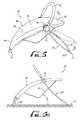
- FIG. 5is a perspective view of the rocker of FIG. 1 , showing a plurality of configurations of the frame according to an example embodiment of the present invention.
- FIG. 6Ais a side view of the rocker of FIG. 1 resting on a support surface, the frame being positioned in an expanded and upright configuration.
- FIG. 6Bis a side view of the rocker of FIG. 1 resting on a support surface, the frame being positioned in an expanded and reclined configuration.
- FIG. 6Cis a side view of the rocker of FIG. 1 , showing the frame being positioned in a collapsed or storage configuration.
- FIG. 7is a perspective view of the rocker of FIG. 6C , showing a user holding the rocker with one hand by grasping a portion of the frame.
- FIG. 8is a rear perspective view of the rocker of FIG. 1 .
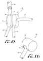
- FIG. 9is a detailed view of a pivot coupling of the rocker of FIG. 8 .
- FIG. 10is a rear perspective view of the pivot coupling and canopy support of FIG. 9 .
- FIG. 11Ais a perspective view of a pivot coupling for use with a rocker according to another example embodiment of the present invention.
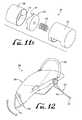
- FIG. 11Bis an exploded perspective view of the pivot coupling of FIG. 11A .
- FIG. 12is a perspective view of a rocker according to another example embodiment of the present invention.
- FIG. 13is a perspective view of a rocker frame according to another example embodiment of the present invention.
- FIGS. 1-3show a rocker 10 according to an example embodiment of the present invention.
- the rocker 10generally comprises a collapsible frame 12 having a first frame portion 20 and a second frame portion 30 , which are pivotally coupled together and configured to rest on a support surface S (see FIG. 6A ) for rocking in a side-to-side motion (see direction arrow in FIG. 1 ).
- the collapsible frame 12is configured to support an infant receiving receptacle or seat 80 (adapted for receiving an infant) and the first and second frame portions 20 , 30 are convertible between an erect or extended configuration, as shown in FIG.
- the seat 80defines a head end and a foot end longitudinally opposite one another for receiving the infant's head and feet, and rocks in a side-to-side direction generally transverse or perpendicular to the head-to-foot longitudinal direction.
- the rocker 10can be folded to the collapsed configuration for travel or storage and can be unfolded to the extended configuration for rocking side-to-side.
- the second frame portion 30is repositionable between at least two angular positions such that the recline angle of the seat 80 (as will be described below) can be selectively adjusted by a caregiver.
- the first and second frame portions 20 , 30are pivotally mounted together by hubs or pivot couplings 40 such that the second frame portion 30 can pivot relative to the first frame portion 20 .
- the pivot couplings 40are generally positioned between the head and foot ends of the seat 80 , which provides greater structural integrity to the frame 12 in addition to stability.
- the pivot couplings 40are positioned between the head and foot ends of the seat 80 and generally closer to the head end than the foot end.
- the first and second frame portions 20 , 30each comprise a pair of legs 22 , 32 and rocking surfaces or base portions 26 , 36 at their distal ends, opposite the hubs 40 , whereby the first and second frame portions each comprise a generally U-shaped and/or V-shaped member connected at their open ends by the hub.
- the legs 22 , 32are generally coupled to the hubs 40 and the base portions 26 , 36 are configured to rest on a support surface.
- the base portions 26 , 36are arcuate or smoothly curved such that the frame 12 (with the frame portions 20 , 30 extending therefrom and the base portions 26 , 36 resting on the support surface) rocks in a rocking motion back and forth, side-to-side on the support surface.
- the first and second frame portions 20 , 30are optionally formed of continuous lengths or coupled segments of tubing or rods, for example constructed of plastic, aluminum, steel or other metals and/or substantially rigid structural material(s).
- the length of the first frame portion 20is generally longer than the second frame portion 30 as shown in FIG. 1 , for example about 1.5 to 2 times as long, to create a dynamic rocking motion.
- the first and second frame portions 20 , 30can be about the same length or have any desired relative lengths.
- the rocker 10can be manually rocked by a caregiver, and in other embodiments the rocker 10 optionally can be driven by other means, such as for example by an electric motor.
- the legs 22 of the first frame portionsgenerally extend towards a front end of the rocker 10 in a generally arc-like or curved direction until joining the base portion 26 .
- the legs 32 of the second frame portion 30(pivotally mounted to the pivot couplings 40 ) extend from the pivot couplings 40 in a back, downward, and curved direction where they join the base portion 36 .
- the radius or curved shape of the legs 22 , 32is substantially similar.
- the second frame portion 30can pivot relative to the first frame portion 20 such that the distance between the base portions 26 , 36 is adjusted. For example, as shown in FIG.
- the second frame portionis pivotal about a transverse axis A and the extension thereof (e.g., distance between the base portions 26 , 36 ) is defined along a longitudinal axis B, which extends generally perpendicular to axis A.
- stops 37are optionally provided at the intersection of the legs 32 and the rocker portion 36 to limit the extent the rocker is capable of rocking, for example about 30-70 degrees in either of the side-to-side directions.
- the stops 37are preferably configured such that the rotational momentum of the rocker when released from its maximum angle in one of the side-to-side directions (with our without an infant in the seat) does not cause the rocker to tip over when reaching the other of the side-to-side directions.
- a seat support tube 50(comprising arms 52 and a radiused portion 54 ) generally extends from the pivot couplings 40 at the head end of the seat area longitudinally opposite the first frame portion 20 , which provides additional support for the seat 80 .
- the first frame portion 20extends continuously to form the seat support tube 50 at the head end.
- the seat support tube 50is fixed to the pivot couplings 40 such that the tube 50 does not pivot relative to the first frame portion 20 .
- the support tube 50can be pivotally mounted to provide pivotal movement relative to the first frame portion 20 for adjustment of the head angle of the seat.
- a toy bar 60is pivotally mounted to the pivot couplings 40 for providing pivotal movement between an upright or in-use position and a collapsed or storage position (see FIG. 5 ).
- the toy bar 60is optionally covered by soft goods, such as a foam cushioning material and a fabric cover material (see FIG. 10 ),
- the toy bar 60can be provided for attachment of toys, pull tags, etc. for entertaining the infant.
- the toy bar 60may be configured to be a one-arm or mobile toy bar, a canopy or other apparatus to provide entertainment for the infant.
- a foot panel 70is optionally provided between the legs 22 of the first frame portion 20 at the foot end of the seat to provide for additional bracing of the rocker 10 and support of the infant's feet.
- the foot panel 70is constructed from a plastic or other substantially rigid material and is shaped to generally follow the curved contour of the first frame portion 20 , for example, such that the legs of an infant seated within the seat 80 are comfortably positioned thereon (i.e., a portion of the seat 80 covering the panel 70 ).
- the foot panel 70generally comprises a support or bracing system 72 for supporting the front frame portion 20 in a non-rocking configuration.
- at least one pivotally mounted foot or leg 74can be provided for pivotal extension (extended position shown in solid lines in FIG.
- the foot panel 70comprises recessed channels 76 for receiving and retaining the feet or legs 74 in a retracted position (shown in broken lines in FIG. 4 ) when the rocker 10 is intended to be rocked.
- the feet 74pivot about a pin coupling or hinge between an extended position and a retracted position, but in alternate forms may extend telescopingly, axially or otherwise.
- the foot panel 70can comprise additional features or accessories 77 , including but not limited to, a vibration unit, music player, speakers, other electronics, batteries, etc.
- the seat 80is generally in the form of a removable and washable soft goods component for receiving and supporting an infant therein.
- the seatcomprises a sling or receptacle having first and second sides 82 , a foot end 84 , a leg portion 86 , a back portion 87 , and a harness 90 (see FIG. 5 ).
- at least portions of the edge or periphery of the seat 80comprise one or more attachment members, pockets or lips (e.g., engagement features) for providing engagement with one or more portions of the frame 12 .
- the upper portion of the back portion 87is attached to the seat support tube 50 and the foot end 84 is pulled tightly and wrapped around the sides of the first frame portion 20 (and foot panel 70 ), wherein a buckle or other attachment means (not shown) is provided for interengagement to removably secure the foot end 84 thereto.
- the seat 80 and/or fame 12can comprise other interengagement features, clips, buckles, snaps, couplings, etc. for removable engagement of the seat 80 to the frame 12 .
- the harness 90is generally configured to restrain at least the waist and the crotch of the infant.
- the harness 90may include other forms of restraints (e.g., shoulder straps, etc.), or may not include any restraints.
- the rocker 10is preferably movable between a plurality of configurations.
- the rocker 10is preferably movable between an erect or extended configuration (see FIGS. 6A-B ) and a collapsed or compact/folded configuration (see FIGS. 6C-7 ).
- the pivot couplings 40each comprise push buttons 47 or other lock releases to free engagement of the second frame portion 30 from the first frame portion 20 at the hub 40 such that the second frame portion 30 can selectively pivot relative to the first frame portion 20 .
- the pivot couplingscan be locked in three distinct positions, and the push buttons (when pressed simultaneously) free the second leg portion 30 to allow pivotal portion thereof relative to the first leg portion 20 to vary the seat position or inclination.
- the rocker 10can preferably be configured to provide a plurality of inclination angles relative to the support surface S.
- the second frame portion 30is positioned relative to the first frame portion 20 (e.g., an upright extended configuration) such that the back portion 87 of the seat 80 is at an incline angle ⁇ of about 45 degrees relative to the support surface.
- the second frame portion 30is positioned relative to the first frame portion 20 (e.g., a reclined extended configuration) such that the back portion 87 of the seat 80 is at an incline angle ⁇ of about 32 degrees relative to the support surface.
- the second frame portion 30can be configured to be positioned as desired to provide the back portion 87 of the seat 80 at other included angles as desired, for example between about 0-80 degrees of inclination.
- the second frame portion 30is generally adjacent the first frame portion and extending in a similar direction.
- the base portion 26 of the first frame portion 20can be used as a handle for carrying the rocker by a caregiver (see FIG. 7 ).
- the second frame portion 30is generally adjacent the first frame portion 20 such that the base portions 26 , 36 are generally adjacent and aligned with one another.
- the curved directions of the legs 22 , 32are preferably similarly configured and aligned with each other that they can provide a compact nesting fit when collapsed.
- the base portion 26acts as a handle for providing a grasping area for carrying the rocker 10 .
- the handlecan be configured with rounded gripping surfaces or otherwise as desired to provide for comfort and ease of use for the caregiver or user that is grasping and carrying the rocker 10 .
- each pivot coupling 40preferably provides for the selective pivotal motion of the second leg portion 30 relative to the first leg portion 20 by operation of the push button lock releases 47 .
- both push buttonsmust be pressed at the same time (simultaneously) in order to allow pivotal movement of the second leg portion 30 .
- each pivot coupling 40generally comprises an inboard portion 42 , an intermediate portion 44 , and an outboard portion 46 .
- the leg 22 and the seat support tube 52are generally rigidly connected to the inboard portion 42 , the intermediate portion pivotally mounts to the inboard portion 42 and receives the leg portion 32 , and the outboard portion 46 pivotally mounts to the inboard and intermediate portions 42 , 44 and receives the toy bar 60 .
- the pivot coupling 40is configured for with sockets or couplings for receiving or fastening the legs, tubes, bars, etc. for connection therewith.
- the push button 47is positioned near the outboard portion 46 of the pivot coupling 40 to be pushed and actuated for movement into the pivot coupling 40 and release a locking mechanism therein such that the leg portion 32 can be repositioned in either of the other two positions (three total positions—collapsed/storage, expanded/upright, and expanded/reclined).
- the locking mechanism that is within the pivotal couplingcan comprise four or more distinct positions such that the second frame portion can be locked at four or more positions, or can provide a continuous range of positioning adjustment to the inclination of the seat 80 .
- the push button 47can be replaced with a switch or other pivotally mounted member for actuation thereof to lock and unlock the second frame portion 30 relative to the first frame portion 20 .
- the seatcan comprise one or more zippers or other adjustment features for selectively expanding/contracting the head and/or foot ends of the seat 80 such that the angle of inclination of the seat 80 relative to the ground surface is adjusted without adjusting the angle of the second frame portion 30 relative to the first frame portion 20 .
- one or more portions of the seat support tube 50may be formed with the legs 22 of the first frame portion 20 .
- a flattened portionmay be provided on one or both legs/tubes (including the legs 32 and toy bar 60 ) to provide ease of attachment and functionality of the pivot couplings 40 .
- FIGS. 11A-Bshow a pivotal coupling 140 according to another example embodiment of the present invention.
- the pivotal coupling 140generally comprises an outer housing member 142 , an internal member 144 for receiving portions of the leg 132 , and a locking mechanism.
- the locking mechanismcomprises a gear 150 having a radial array of locking teeth 152 for interengagement with a complementary radial array of recesses 146 formed within the internal member 144 , and a biasing member 154 for biasing the gear 150 against the internal member 144 to engage the teeth 152 with the recesses 146 to lock the frame in a selected position.
- a push button or other releasecan be actuated to disengage the teeth 152 from the recesses 146 such that the internal member 144 (and leg 132 coupled thereto) can pivot relative to the outer housing 142 , thereby providing adjustment to the second frame portion.
- the legs of the first frame portion, the arms of the seat support tube, and the toy barcan be mounted as desired to portions of the outer housing 142 .
- the legs of the first frame portion and the arms of the seat support tubeare rigidly attached to the outer housing 142 and the toy bar is pivotally mounted to the outer housing 142 .
- FIG. 12shows a rocker 200 according to another example embodiment of the present invention.
- the first frame portion 220comprises a V-shaped base portion 226 and the second frame portion 230 comprises a radiused or arcuate base portion.
- the V-shaped base portion 226pivots on the support surface as the radiused base portion 236 rocks on the support surface, thereby providing a sharper or more pronounced non-traditional side-to-side rocking motion.
- the rocking motion at the rear ende.g., rocking about the radiused base portion of the second frame portion 230
- the rocking motion at the front ende.g., rocking about the V-shaped pivot or base portion 226 ).
- the V-shaped base portion 226may be replaced with a more arcuate-like base portion (as similarly described above), but may comprise a radius of curvature that is smaller than the radius of curvature of the radiused base portion of the second frame portion 230 , which can create a more pronounced rocking motion at the rear end.
- stops 237are provided at the intersection of the legs 232 and the rocker base portion such that the range of motion of the rocker 200 is limited at each end of the range of rocking motion to prevent tipping.
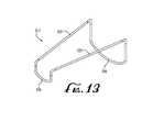
- FIG. 13shows a rocker frame 312 according to another example embodiment of the present invention.
- a pair of upper frame members 325extend longitudinally along left and right sides of the frame between corresponding pairs of upright front legs and rear legs, with distal or lower ends of the legs being connected together by transversely extending rocker portions 326 , 336 .
- the upper frame members 325are preferably configured for suspending or supporting the soft goods seat or support sling (unshown).
- rigid or semi-rigid elbowsare provided for coupling the front and rear legs to the upper frame members 325 .
- the elbowsmay comprise pivots to provide for collapsing or adjusting and angle of inclination of the seat as similarly described above.
- the rocker apparatus of the present inventionmay be utilized for other side-to-side motion devices (i.e., rocking in a direction generally transverse to the head-to-foot longitudinal direction) that provide varying degrees of inclination relative to the support surface.
- the frame and/or seatcan be configured to recline the infant at about 10-30 degrees relative to the support surface and provide a rocking, side-to-side motion (e.g., a sleeper).
- the frame and/or seatcan be configured to recline the infant between about 0-10 degrees relative to the support surface and provide a rocking, side-to-side motion (e.g., a bassinet).
- the infant receiving receptaclemay or may not have a harness and/or other restraints depending on the particular motion device (rocker, sleeper, or bassinet).
- rocker, sleeper, or bassinettypically do not contain a restraint system in the occupant area
- sleeperstypically are not required to have restraints but may have waist and crotch restraints
- rockerstypically must have at least waist and crotch restraints.
Landscapes
- Carriages For Children, Sleds, And Other Hand-Operated Vehicles (AREA)
- Health & Medical Sciences (AREA)
- General Health & Medical Sciences (AREA)
- Pediatric Medicine (AREA)
Abstract
Description
Claims (37)
Priority Applications (1)
| Application Number | Priority Date | Filing Date | Title |
|---|---|---|---|
| US14/327,871US9848715B2 (en) | 2013-07-12 | 2014-07-10 | Rocker |
Applications Claiming Priority (2)
| Application Number | Priority Date | Filing Date | Title |
|---|---|---|---|
| US201361845516P | 2013-07-12 | 2013-07-12 | |
| US14/327,871US9848715B2 (en) | 2013-07-12 | 2014-07-10 | Rocker |
Publications (2)
| Publication Number | Publication Date |
|---|---|
| US20150015036A1 US20150015036A1 (en) | 2015-01-15 |
| US9848715B2true US9848715B2 (en) | 2017-12-26 |
Family
ID=51967354
Family Applications (1)
| Application Number | Title | Priority Date | Filing Date |
|---|---|---|---|
| US14/327,871Active2035-02-18US9848715B2 (en) | 2013-07-12 | 2014-07-10 | Rocker |
Country Status (2)
| Country | Link |
|---|---|
| US (1) | US9848715B2 (en) |
| CN (1) | CN203969871U (en) |
Cited By (3)
| Publication number | Priority date | Publication date | Assignee | Title |
|---|---|---|---|---|
| US20230129979A1 (en)* | 2021-10-27 | 2023-04-27 | Rocking Inc. | Portable rebounding device with adjustable and collapsible features |
| US11889930B1 (en) | 2022-12-05 | 2024-02-06 | Monahan Products, LLC | Foldable child seat |
| USD1031339S1 (en) | 2019-11-18 | 2024-06-18 | Kids2, Inc. | Rocker |
Families Citing this family (12)
| Publication number | Priority date | Publication date | Assignee | Title |
|---|---|---|---|---|
| US9622584B2 (en)* | 2013-07-19 | 2017-04-18 | Max ID NY LLC | Portable chair |
| US9918561B2 (en) | 2013-08-09 | 2018-03-20 | Kids Ii, Inc. | Access optimized child support device |
| FR3039048B1 (en)* | 2015-07-22 | 2018-03-02 | Beaba | FOLDING SEAT EQUIPPED WITH POSITION BLOCKING SYSTEM |
| US20180070740A1 (en)* | 2016-09-15 | 2018-03-15 | Kids Ii, Inc. | Children's motion device |
| USD826592S1 (en) | 2017-06-16 | 2018-08-28 | Kids Ii, Inc. | Child support device |
| USD826590S1 (en) | 2017-06-16 | 2018-08-28 | Kids Ii, Inc. | Child support device |
| USD826591S1 (en) | 2017-06-16 | 2018-08-28 | Kids Ii, Inc. | Child support device |
| CN210300375U (en)* | 2018-05-07 | 2020-04-14 | 明门(中国)幼童用品有限公司 | Foldable containing device |
| US11197560B2 (en) | 2018-05-07 | 2021-12-14 | Wonderland Switzerland Ag | Foldable bassinet |
| US10575657B2 (en) | 2018-06-06 | 2020-03-03 | Mattel, Inc. | Convertible auto-rocking rocker |
| US11364167B2 (en)* | 2019-02-12 | 2022-06-21 | GE Precision Healthcare LLC | Neonatal care system with sling sleep device |
| JP2024535680A (en)* | 2021-08-13 | 2024-10-02 | グラコ・チルドレンズ・プロダクツ・インコーポレイテッド | SYSTEMS, METHODS AND APPARATUS FOR MULTI-SENSORY HAPTAL AUDIO SYSTEMS FOR CHILDREN'S PRODUCTS - Patent application |
Citations (68)
| Publication number | Priority date | Publication date | Assignee | Title |
|---|---|---|---|---|
| US341238A (en) | 1886-05-04 | Folding convertible crib | ||
| US1812699A (en) | 1929-10-09 | 1931-06-30 | Raymond M Hursh | Cradle |
| US2688997A (en) | 1950-09-16 | 1954-09-14 | Fred H Heilmann | Combination rocker and bed |
| US2788056A (en) | 1956-03-19 | 1957-04-09 | Blazon Inc | Child's collapsible rocking chair |
| US2854062A (en) | 1955-10-05 | 1958-09-30 | Albert S Hetchler | Rocking chair |
| US3047333A (en) | 1960-06-01 | 1962-07-31 | Victoria Prec Works Company Lt | Child's collapsible rocking chair |
| US3110519A (en) | 1961-06-19 | 1963-11-12 | Victor A Chernivsky | Baby chair |
| US3119124A (en) | 1962-05-31 | 1964-01-28 | Robert D Krauss | Play pen |
| US3158877A (en) | 1963-01-29 | 1964-12-01 | Gary D Cooper | Supporting rocker frame |
| US3206772A (en) | 1963-10-31 | 1965-09-21 | Thayer Inc | Folding playpen |
| US3309718A (en) | 1965-10-05 | 1967-03-21 | Thayer Inc | Folding playpen |
| US3890660A (en) | 1974-05-13 | 1975-06-24 | Richard C Pedler | Furniture |
| US4371206A (en) | 1981-02-17 | 1983-02-01 | Kolcraft Products, Inc. | Rockable infant seat/cradle |
| US4573224A (en) | 1984-06-01 | 1986-03-04 | Graco Metal Products Inc. | Folding playpen |
| US4635305A (en) | 1984-11-29 | 1987-01-13 | Andre Wyss | Foldable bed |
| US4674795A (en) | 1986-07-10 | 1987-06-23 | Nelson Jonathan M | Chair frame |
| US4718715A (en) | 1987-04-07 | 1988-01-12 | Ho Ching Chou | Adjustable folding baby chair |
| US5011221A (en) | 1983-11-08 | 1991-04-30 | Century Products Company | Baby carrier |
| US5172955A (en) | 1991-02-28 | 1992-12-22 | Gerry Baby Products Company | Bouncing infant seat reclining between upright position and recline position with distinct resilient element |
| US5178438A (en) | 1991-02-07 | 1993-01-12 | Udo Beger | Infant rocking device |
| US5203611A (en) | 1991-10-21 | 1993-04-20 | Children On The Go, Inc. | Infant bounce and rocking chair |
| US5207478A (en) | 1991-02-28 | 1993-05-04 | Gerry Baby Products Company | Collapsible infant seat |
| US5269591A (en) | 1992-06-24 | 1993-12-14 | Playskool Baby, Inc. | Bouncer seat for infant |
| US5308143A (en) | 1992-09-23 | 1994-05-03 | Joanna A. Nichols | Safety rocker for an infant seat |
| US5360258A (en) | 1992-01-07 | 1994-11-01 | Maurice Adam | Portable single and multiple unit baby support seat |
| US5503458A (en) | 1993-07-02 | 1996-04-02 | Item New Product Development, Inc. | Portable infant seat |
| US5617594A (en) | 1995-11-06 | 1997-04-08 | Jina Manufacturing Thai Co., Ltd. | Foldable cradle frame |
| US5694655A (en)* | 1996-04-16 | 1997-12-09 | Shepler; David C. | Rocking collapsible bassinet |
| US5868459A (en) | 1997-04-10 | 1999-02-09 | Kolcraft Enterprises, Inc. | Bouncer with positive lock |
| US6174028B1 (en) | 1999-06-01 | 2001-01-16 | Link Treasure Limited | Infant rocking chair |
| US6299247B1 (en) | 1993-10-01 | 2001-10-09 | Evenflo Company, Inc. | Child exerciser/rocker |
| US6341816B1 (en) | 2000-03-31 | 2002-01-29 | Link Treasure Limited | Collapsible rocking chair |
| US6361106B1 (en)* | 2000-07-11 | 2002-03-26 | Mien Chen Huang | Folding collapsible frame structure for a baby rocking chair |
| US6378940B1 (en)* | 1999-11-08 | 2002-04-30 | Summer Infant Products, Inc. | Bouncer seat and drive mechanism therefor |
| US20030020317A1 (en)* | 2001-07-30 | 2003-01-30 | Charles Keegan | Baby bouncer |
| US6520862B1 (en) | 2001-10-02 | 2003-02-18 | Mattel, Inc. | Collapsible infant swing |
| US6540292B2 (en) | 1999-05-28 | 2003-04-01 | Mattel, Inc. | Adjustable rocker seat |
| US6679779B2 (en)* | 2001-11-16 | 2004-01-20 | Link Treasure Limited | Structure for an infant's rocket |
| US6682148B1 (en) | 2002-12-25 | 2004-01-27 | Owen Chen | Baby rocking chair frame |
| US6682137B2 (en) | 2000-05-05 | 2004-01-27 | Ben Ming Hsia | Adjustable frame of rocker |
| US6687928B1 (en) | 2002-09-13 | 2004-02-10 | Michelle Wilson | Portable child's bed |
| US6811217B2 (en) | 2002-08-15 | 2004-11-02 | Mattel, Inc. | Rocker device |
| US6877802B2 (en) | 2003-04-15 | 2005-04-12 | Graco Children's Products Inc. | Foldable infant seat |
| US6902230B2 (en) | 2003-08-15 | 2005-06-07 | Wonderland Nurserygoods Co., Ltd. | Foldable child support device |
| US20060103178A1 (en) | 2004-11-18 | 2006-05-18 | Wun Tony K K | Collapsible rocker chair |
| US20070007804A1 (en)* | 2005-03-24 | 2007-01-11 | Cosco Management, Inc. | Juvenile relaxation apparatus with motion system |
| US20070096460A1 (en) | 2005-10-27 | 2007-05-03 | Red Lan | Sleeve assembly and rocking chair incorporating the same |
| US7445559B2 (en) | 2005-03-16 | 2008-11-04 | Graco Children's Products Inc. | Swing with support base |
| US7455353B2 (en) | 1997-08-14 | 2008-11-25 | Mattel, Inc. | Collapsible bassinet/infant seat with canopy |
| US7506922B2 (en)* | 2006-05-08 | 2009-03-24 | Mattel, Inc. | Reconfigurable child receiving rocker device |
| US7727078B2 (en) | 2006-10-31 | 2010-06-01 | Graco Children's Products Inc. | Child seat canopy illumination and media projection |
| US7779490B2 (en) | 2006-07-07 | 2010-08-24 | BabyBjörn AB | Babysitter with bottom frame |
| US7789762B2 (en) | 2005-11-03 | 2010-09-07 | Graco Children's Products Inc. | Child motion device |
| US7824273B2 (en) | 2005-11-03 | 2010-11-02 | Graco Children's Products Inc. | Child motion device |
| US7837570B2 (en) | 2005-07-27 | 2010-11-23 | Kukutoys Co., Ltd. | Swing device having circuit for generating repulsive force |
| US20110127810A1 (en)* | 2009-12-01 | 2011-06-02 | Wicky Lee | Collapsible infant bouncer |
| US20110148155A1 (en) | 2009-12-22 | 2011-06-23 | Mattel, Inc. | Collapsible Infant Support |
| US8029377B2 (en) | 2005-11-03 | 2011-10-04 | Graco Children's Products Inc. | Child motion device |
| US8038207B2 (en) | 2005-08-16 | 2011-10-18 | Regalo International, Llc | Rocker and booster child seat |
| US8182355B2 (en) | 2004-02-06 | 2012-05-22 | Mattel, Inc. | Free-standing jumping device |
| US8187111B2 (en) | 2005-11-03 | 2012-05-29 | Graco Children's Products Inc. | Child motion device |
| US8205943B2 (en) | 2009-08-04 | 2012-06-26 | Wonderland Nursery Goods Co., Ltd | Foldable rocking chair |
| US20120181830A1 (en) | 2009-10-28 | 2012-07-19 | Bombol Limited | Containing structure for small children fitted with a dynamic backrest |
| US20120180212A1 (en)* | 2009-10-27 | 2012-07-19 | Bombol Limited | Frame supported by laminae of lessened flexibility suitable for use in cradles for small children |
| US20130214574A1 (en) | 2009-12-22 | 2013-08-22 | Mattel, Inc. | Collapsible infant support |
| US20140210238A1 (en)* | 2013-01-26 | 2014-07-31 | Bruce G. Kania | Rocker-equipped hunting blind |
| US8845023B2 (en)* | 2011-01-28 | 2014-09-30 | Lerado (Zhong Shan) Industrial Co., Ltd. | Convertible rocking chair with multi-using modes |
| US8844072B2 (en)* | 2012-06-05 | 2014-09-30 | Wonderland Nurserygoods Company Limited | Infant supporting apparatus |
- 2014
- 2014-07-10USUS14/327,871patent/US9848715B2/enactiveActive
- 2014-07-11CNCN201420384391.7Upatent/CN203969871U/ennot_activeExpired - Lifetime
Patent Citations (70)
| Publication number | Priority date | Publication date | Assignee | Title |
|---|---|---|---|---|
| US341238A (en) | 1886-05-04 | Folding convertible crib | ||
| US1812699A (en) | 1929-10-09 | 1931-06-30 | Raymond M Hursh | Cradle |
| US2688997A (en) | 1950-09-16 | 1954-09-14 | Fred H Heilmann | Combination rocker and bed |
| US2854062A (en) | 1955-10-05 | 1958-09-30 | Albert S Hetchler | Rocking chair |
| US2788056A (en) | 1956-03-19 | 1957-04-09 | Blazon Inc | Child's collapsible rocking chair |
| US3047333A (en) | 1960-06-01 | 1962-07-31 | Victoria Prec Works Company Lt | Child's collapsible rocking chair |
| US3110519A (en) | 1961-06-19 | 1963-11-12 | Victor A Chernivsky | Baby chair |
| US3119124A (en) | 1962-05-31 | 1964-01-28 | Robert D Krauss | Play pen |
| US3158877A (en) | 1963-01-29 | 1964-12-01 | Gary D Cooper | Supporting rocker frame |
| US3206772A (en) | 1963-10-31 | 1965-09-21 | Thayer Inc | Folding playpen |
| US3309718A (en) | 1965-10-05 | 1967-03-21 | Thayer Inc | Folding playpen |
| US3890660A (en) | 1974-05-13 | 1975-06-24 | Richard C Pedler | Furniture |
| US4371206A (en) | 1981-02-17 | 1983-02-01 | Kolcraft Products, Inc. | Rockable infant seat/cradle |
| US5011221A (en) | 1983-11-08 | 1991-04-30 | Century Products Company | Baby carrier |
| US4573224A (en) | 1984-06-01 | 1986-03-04 | Graco Metal Products Inc. | Folding playpen |
| US4635305A (en) | 1984-11-29 | 1987-01-13 | Andre Wyss | Foldable bed |
| US4674795A (en) | 1986-07-10 | 1987-06-23 | Nelson Jonathan M | Chair frame |
| US4718715A (en) | 1987-04-07 | 1988-01-12 | Ho Ching Chou | Adjustable folding baby chair |
| US5178438A (en) | 1991-02-07 | 1993-01-12 | Udo Beger | Infant rocking device |
| US5172955A (en) | 1991-02-28 | 1992-12-22 | Gerry Baby Products Company | Bouncing infant seat reclining between upright position and recline position with distinct resilient element |
| US5207478A (en) | 1991-02-28 | 1993-05-04 | Gerry Baby Products Company | Collapsible infant seat |
| US5203611A (en) | 1991-10-21 | 1993-04-20 | Children On The Go, Inc. | Infant bounce and rocking chair |
| US5360258A (en) | 1992-01-07 | 1994-11-01 | Maurice Adam | Portable single and multiple unit baby support seat |
| US5269591A (en) | 1992-06-24 | 1993-12-14 | Playskool Baby, Inc. | Bouncer seat for infant |
| US5308143A (en) | 1992-09-23 | 1994-05-03 | Joanna A. Nichols | Safety rocker for an infant seat |
| US5503458A (en) | 1993-07-02 | 1996-04-02 | Item New Product Development, Inc. | Portable infant seat |
| US6299247B1 (en) | 1993-10-01 | 2001-10-09 | Evenflo Company, Inc. | Child exerciser/rocker |
| US5617594A (en) | 1995-11-06 | 1997-04-08 | Jina Manufacturing Thai Co., Ltd. | Foldable cradle frame |
| US5694655A (en)* | 1996-04-16 | 1997-12-09 | Shepler; David C. | Rocking collapsible bassinet |
| US5868459A (en) | 1997-04-10 | 1999-02-09 | Kolcraft Enterprises, Inc. | Bouncer with positive lock |
| US7455353B2 (en) | 1997-08-14 | 2008-11-25 | Mattel, Inc. | Collapsible bassinet/infant seat with canopy |
| US6540292B2 (en) | 1999-05-28 | 2003-04-01 | Mattel, Inc. | Adjustable rocker seat |
| US6174028B1 (en) | 1999-06-01 | 2001-01-16 | Link Treasure Limited | Infant rocking chair |
| US6378940B1 (en)* | 1999-11-08 | 2002-04-30 | Summer Infant Products, Inc. | Bouncer seat and drive mechanism therefor |
| US6341816B1 (en) | 2000-03-31 | 2002-01-29 | Link Treasure Limited | Collapsible rocking chair |
| US6682137B2 (en) | 2000-05-05 | 2004-01-27 | Ben Ming Hsia | Adjustable frame of rocker |
| US6361106B1 (en)* | 2000-07-11 | 2002-03-26 | Mien Chen Huang | Folding collapsible frame structure for a baby rocking chair |
| US20030020317A1 (en)* | 2001-07-30 | 2003-01-30 | Charles Keegan | Baby bouncer |
| US6520862B1 (en) | 2001-10-02 | 2003-02-18 | Mattel, Inc. | Collapsible infant swing |
| US6824472B2 (en) | 2001-10-02 | 2004-11-30 | Fisher-Price, Inc. | Collapsible infant swing |
| US6857966B2 (en) | 2001-10-02 | 2005-02-22 | Fisher-Price, Inc. | Collapsible infant swing |
| US6679779B2 (en)* | 2001-11-16 | 2004-01-20 | Link Treasure Limited | Structure for an infant's rocket |
| US6811217B2 (en) | 2002-08-15 | 2004-11-02 | Mattel, Inc. | Rocker device |
| US6687928B1 (en) | 2002-09-13 | 2004-02-10 | Michelle Wilson | Portable child's bed |
| US6682148B1 (en) | 2002-12-25 | 2004-01-27 | Owen Chen | Baby rocking chair frame |
| US6877802B2 (en) | 2003-04-15 | 2005-04-12 | Graco Children's Products Inc. | Foldable infant seat |
| US6902230B2 (en) | 2003-08-15 | 2005-06-07 | Wonderland Nurserygoods Co., Ltd. | Foldable child support device |
| US8182355B2 (en) | 2004-02-06 | 2012-05-22 | Mattel, Inc. | Free-standing jumping device |
| US20060103178A1 (en) | 2004-11-18 | 2006-05-18 | Wun Tony K K | Collapsible rocker chair |
| US7445559B2 (en) | 2005-03-16 | 2008-11-04 | Graco Children's Products Inc. | Swing with support base |
| US20070007804A1 (en)* | 2005-03-24 | 2007-01-11 | Cosco Management, Inc. | Juvenile relaxation apparatus with motion system |
| US7837570B2 (en) | 2005-07-27 | 2010-11-23 | Kukutoys Co., Ltd. | Swing device having circuit for generating repulsive force |
| US8038207B2 (en) | 2005-08-16 | 2011-10-18 | Regalo International, Llc | Rocker and booster child seat |
| US20070096460A1 (en) | 2005-10-27 | 2007-05-03 | Red Lan | Sleeve assembly and rocking chair incorporating the same |
| US7789762B2 (en) | 2005-11-03 | 2010-09-07 | Graco Children's Products Inc. | Child motion device |
| US7824273B2 (en) | 2005-11-03 | 2010-11-02 | Graco Children's Products Inc. | Child motion device |
| US8029377B2 (en) | 2005-11-03 | 2011-10-04 | Graco Children's Products Inc. | Child motion device |
| US8187111B2 (en) | 2005-11-03 | 2012-05-29 | Graco Children's Products Inc. | Child motion device |
| US7506922B2 (en)* | 2006-05-08 | 2009-03-24 | Mattel, Inc. | Reconfigurable child receiving rocker device |
| US7779490B2 (en) | 2006-07-07 | 2010-08-24 | BabyBjörn AB | Babysitter with bottom frame |
| US7727078B2 (en) | 2006-10-31 | 2010-06-01 | Graco Children's Products Inc. | Child seat canopy illumination and media projection |
| US8205943B2 (en) | 2009-08-04 | 2012-06-26 | Wonderland Nursery Goods Co., Ltd | Foldable rocking chair |
| US20120180212A1 (en)* | 2009-10-27 | 2012-07-19 | Bombol Limited | Frame supported by laminae of lessened flexibility suitable for use in cradles for small children |
| US20120181830A1 (en) | 2009-10-28 | 2012-07-19 | Bombol Limited | Containing structure for small children fitted with a dynamic backrest |
| US20110127810A1 (en)* | 2009-12-01 | 2011-06-02 | Wicky Lee | Collapsible infant bouncer |
| US20110148155A1 (en) | 2009-12-22 | 2011-06-23 | Mattel, Inc. | Collapsible Infant Support |
| US20130214574A1 (en) | 2009-12-22 | 2013-08-22 | Mattel, Inc. | Collapsible infant support |
| US8845023B2 (en)* | 2011-01-28 | 2014-09-30 | Lerado (Zhong Shan) Industrial Co., Ltd. | Convertible rocking chair with multi-using modes |
| US8844072B2 (en)* | 2012-06-05 | 2014-09-30 | Wonderland Nurserygoods Company Limited | Infant supporting apparatus |
| US20140210238A1 (en)* | 2013-01-26 | 2014-07-31 | Bruce G. Kania | Rocker-equipped hunting blind |
Cited By (4)
| Publication number | Priority date | Publication date | Assignee | Title |
|---|---|---|---|---|
| USD1031339S1 (en) | 2019-11-18 | 2024-06-18 | Kids2, Inc. | Rocker |
| US20230129979A1 (en)* | 2021-10-27 | 2023-04-27 | Rocking Inc. | Portable rebounding device with adjustable and collapsible features |
| US12342943B2 (en)* | 2021-10-27 | 2025-07-01 | Rocking Inc. | Portable rebounding device with adjustable and collapsible features |
| US11889930B1 (en) | 2022-12-05 | 2024-02-06 | Monahan Products, LLC | Foldable child seat |
Also Published As
| Publication number | Publication date |
|---|---|
| CN203969871U (en) | 2014-12-03 |
| US20150015036A1 (en) | 2015-01-15 |
Similar Documents
| Publication | Publication Date | Title |
|---|---|---|
| US9848715B2 (en) | Rocker | |
| US9888786B2 (en) | Child sleeping apparatus | |
| US8596670B2 (en) | Stroller | |
| EP1003405B1 (en) | Collapsible bassinet/infant seat with canopy | |
| US9918561B2 (en) | Access optimized child support device | |
| US7445559B2 (en) | Swing with support base | |
| US8567866B2 (en) | Stroller seat pod | |
| US6155579A (en) | Folding child stroller and frame carrier | |
| US6773065B1 (en) | Reclining changing seat | |
| CN202959685U (en) | Lounger | |
| US7517011B2 (en) | Combination child carrier | |
| CN207767956U (en) | The high sleeping apparatus of folding stand and child supporting device | |
| US20150342366A1 (en) | Child sleeping apparatus with folding frame | |
| CN105358405B (en) | stroller | |
| US20110148058A1 (en) | Stroller | |
| GB2352623A (en) | Inter-convertible highchair/ vehicle child seat | |
| CN204393947U (en) | baby support device | |
| CN206182827U (en) | Child supporting device | |
| CN201814213U (en) | Height-adjustable baby dining chair | |
| CN205890959U (en) | Children strutting arrangement that use is optimized | |
| TWI896982B (en) | Foldable carrier, carrier frame of child carrying device, and child carrying device | |
| US20030122352A1 (en) | Device for mounting accessory wheels on stroller | |
| CN216508546U (en) | Lock catch structure, backrest adjusting assembly and seat | |
| CN205107069U (en) | Children's device of sleeping | |
| WO2017183987A1 (en) | Multipurpose child carrier |
Legal Events
| Date | Code | Title | Description |
|---|---|---|---|
| STCF | Information on status: patent grant | Free format text:PATENTED CASE | |
| AS | Assignment | Owner name:REGIONS BANK, GEORGIA Free format text:SECURITY INTEREST;ASSIGNOR:KIDS II, INC.;REEL/FRAME:045008/0508 Effective date:20171221 | |
| AS | Assignment | Owner name:KIDS II, INC., GEORGIA Free format text:ASSIGNMENT OF ASSIGNORS INTEREST;ASSIGNOR:SORIANO, ALEX;REEL/FRAME:044974/0615 Effective date:20120713 | |
| AS | Assignment | Owner name:KIDS2, INC., GEORGIA Free format text:CHANGE OF NAME;ASSIGNOR:KIDS II, INC.;REEL/FRAME:050375/0888 Effective date:20190730 | |
| AS | Assignment | Owner name:WHITE OAK COMMERCIAL FINANCE, LLC, AS COLLATERAL AGENT, CALIFORNIA Free format text:SECURITY INTEREST;ASSIGNORS:KIDS2, INC.;GOT I, LLC;REEL/FRAME:054195/0544 Effective date:20200928 | |
| AS | Assignment | Owner name:GORDON BROTHERS BRANDS, LLC, MASSACHUSETTS Free format text:SECURITY INTEREST;ASSIGNOR:KIDS2, INC.;REEL/FRAME:054251/0711 Effective date:20200928 | |
| AS | Assignment | Owner name:KIDS2, INC., GEORGIA Free format text:RELEASE BY SECURED PARTY;ASSIGNOR:REGIONS BANK;REEL/FRAME:054298/0106 Effective date:20200928 | |
| FEPP | Fee payment procedure | Free format text:ENTITY STATUS SET TO UNDISCOUNTED (ORIGINAL EVENT CODE: BIG.); ENTITY STATUS OF PATENT OWNER: LARGE ENTITY | |
| MAFP | Maintenance fee payment | Free format text:PAYMENT OF MAINTENANCE FEE, 4TH YEAR, LARGE ENTITY (ORIGINAL EVENT CODE: M1551); ENTITY STATUS OF PATENT OWNER: LARGE ENTITY Year of fee payment:4 | |
| AS | Assignment | Owner name:WELLS FARGO BANK, NATIONAL ASSOCIATION, AS AGENT, GEORGIA Free format text:SECURITY AGREEMENT;ASSIGNORS:KIDS2, INC.;GOT I, LLC;GOT II, LLC;AND OTHERS;REEL/FRAME:060413/0821 Effective date:20220622 | |
| AS | Assignment | Owner name:KIDS2, INC., GEORGIA Free format text:RELEASE BY SECURED PARTY;ASSIGNOR:GORDON BROTHERS BRANDS, LLC;REEL/FRAME:060440/0650 Effective date:20220622 | |
| AS | Assignment | Owner name:KIDS2, LLC, GEORGIA Free format text:BUSINESS CONVERSION;ASSIGNOR:KIDS2, INC.;REEL/FRAME:066943/0422 Effective date:20231229 | |
| FEPP | Fee payment procedure | Free format text:MAINTENANCE FEE REMINDER MAILED (ORIGINAL EVENT CODE: REM.); ENTITY STATUS OF PATENT OWNER: LARGE ENTITY |