US9848132B2 - Multi-camera time synchronization - Google Patents
Multi-camera time synchronizationDownload PDFInfo
- Publication number
- US9848132B2 US9848132B2US14/951,482US201514951482AUS9848132B2US 9848132 B2US9848132 B2US 9848132B2US 201514951482 AUS201514951482 AUS 201514951482AUS 9848132 B2US9848132 B2US 9848132B2
- Authority
- US
- United States
- Prior art keywords
- synchronization
- video
- camera
- label
- video frames
- Prior art date
- Legal status (The legal status is an assumption and is not a legal conclusion. Google has not performed a legal analysis and makes no representation as to the accuracy of the status listed.)
- Active, expires
Links
Images


Classifications
- H04N5/247—
- H—ELECTRICITY
- H04—ELECTRIC COMMUNICATION TECHNIQUE
- H04N—PICTORIAL COMMUNICATION, e.g. TELEVISION
- H04N23/00—Cameras or camera modules comprising electronic image sensors; Control thereof
- H04N23/90—Arrangement of cameras or camera modules, e.g. multiple cameras in TV studios or sports stadiums
- H—ELECTRICITY
- H04—ELECTRIC COMMUNICATION TECHNIQUE
- H04N—PICTORIAL COMMUNICATION, e.g. TELEVISION
- H04N5/00—Details of television systems
- H04N5/76—Television signal recording
- H04N5/765—Interface circuits between an apparatus for recording and another apparatus
- H04N5/77—Interface circuits between an apparatus for recording and another apparatus between a recording apparatus and a television camera
- H—ELECTRICITY
- H04—ELECTRIC COMMUNICATION TECHNIQUE
- H04N—PICTORIAL COMMUNICATION, e.g. TELEVISION
- H04N5/00—Details of television systems
- H04N5/76—Television signal recording
- H04N5/91—Television signal processing therefor
Definitions
- This disclosurerelates to a camera system, and more specifically, to time synchronization in multi-camera environments.
- Multi-camera storytellingenables more comprehensive coverage of an event from different perspectives.
- multiple camerasneed to be synchronized when shooting an event. Users are otherwise prevented from editing footage captured by the multiple cameras.
- Cameras' internal clocksare likely to drift and are not very accurate. Users' experiences can be diminished if users are required to synchronize all cameras prior to shooting.
- Adding a master controllersuch as a timing master accessory (e.g., a WiFi remote control) will limit the consumer applications to only those users who proactively synchronize cameras. GPS signals may not provide sufficient time accuracy and at the same time consume a lot of power, thereby reducing a device's battery life.
- FIG. 1 aillustrates a perspective view of a camera system, according to one embodiment.
- FIG. 1 billustrates a perspective view of a rear of the camera system, according to one embodiment.
- FIG. 2 aillustrates a perspective view of a camera for use with the camera system, according to one embodiment.
- FIG. 2 billustrates a perspective view of a rear of a camera for use with the camera system, according to one embodiment.
- FIG. 3is a block diagram illustrating electronic components of a camera, according to one embodiment.
- FIG. 4is a block diagram illustrating a synchronization engine of a camera, according to one embodiment.
- FIG. 5Ais a sequence diagram illustrating a synchronization between cameras, according to one embodiment.
- FIG. 5Bis a flow diagram illustrating a method of aligning video clips and images, according to one embodiment.
- Video clips and imagescan be aligned based on their capturing time to support a multi-camera storytelling.
- Video clips and images captured by one deviceare associated with one or more synchronization labels such as synchronization device labels and synchronization time labels, both of which are generated by the device.
- Synchronization device labelscan be used to identify devices that are synchronized.
- Synchronization time labelsindicate relative timing between devices that are synchronized.
- Each of the two devicescalculates a synchronization device label and a synchronization time label based on the first and second synchronization signals and associates the synchronization device label and synchronization time label with the video frames and images captured by the device.
- Video clips and images captured by synchronized devicescan subsequently be aligned using the associated synchronization device labels and the synchronization time labels, for instance in post-processing.
- a camera systemincludes a camera and a camera housing structured to at least partially enclose the camera.
- the cameracomprises a camera body having a camera lens structured on a front surface of the camera body, various indicators on the front of the surface of the camera body (such as LEDs, displays, and the like), various input mechanisms (such as buttons, switches, and touch-screen mechanisms), and electronics (e.g., imaging electronics, power electronics, etc.) internal to the camera body for capturing images via the camera lens and/or performing other functions.
- the camera housingincludes a lens window structured on the front surface of the camera housing and configured to substantially align with the camera lens, and one or more indicator windows structured on the front surface of the camera housing and configured to substantially align with the camera indicators.
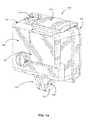
- FIGS. 1 a and 1 billustrate various views of a camera system according to one example embodiment.
- the camera systemincludes, among other components, a camera housing 100 .
- a first housing portion 101includes a front face with four sides (i.e., a top side, bottom side, left side, and right side) structured to form a cavity that receives a camera (e.g. a still camera or video camera), and a second housing portion 102 structured to couple to the first housing portion 101 and securely enclose a camera within the camera housing 100 .
- the first housing portion 101 and second housing portion 102can be pivotally coupled via a hinge mechanism (described in greater detail in FIG. 1 b ), and can securely couple via a latch mechanism 103 .
- the camera housing 100may not include one or more sides or faces.
- the camera housing 100may not include a front or back face, allowing the front face and rear face of the camera to be exposed when partially enclosed by the top side, bottom side, left side, and right side of the camera housing 100 .
- the camera housing 100has a small form factor (e.g., a height of approximately 4 to 6 centimeters, a width of approximately 5 to 7 centimeters, and a depth of approximately 1 to 4 centimeters), and is lightweight (e.g., approximately 50 to 150 grams).
- the camera housing 100can be rigid (or substantially rigid) (e.g., plastic, metal, fiberglass, etc.) or pliable (or substantially pliable) (e.g., leather, vinyl, neoprene, etc.).
- the camera housing 100may be appropriately configured for use in various elements.
- the camera housing 100may comprise a waterproof enclosure that protects a camera from water when used, for example, while surfing or scuba diving.
- Portions of the camera housing 100may include exposed areas to allow a user to manipulate buttons on the camera that are associated with the camera functionality. Alternatively, such areas may be covered with a pliable material to allow the user to manipulate the buttons through the camera housing 100 .
- the top face of the camera housing 100includes an outer shutter button 112 structured so that a shutter button of the camera is substantially aligned with the outer shutter button 112 when the camera is secured within the camera housing 100 .
- the shutter button 112 of the camerais operationally coupled to the outer shutter button 112 so that pressing the outer shutter button 112 allows the user to operate the camera shutter button.
- the front face of the camera housing 100includes a lens window 104 structured so that a lens of the camera is substantially aligned with the lens windows 104 when the camera is secured within the camera housing 100 .
- the lens window 104can be adapted for use with a conventional lens, a wide angle lens, a flat lens, or any other specialized camera lens.
- the camera housing 100includes one or more securing structures 120 for securing the camera housing 100 to one of a variety of mounting devices such as a clip-style mount.
- the camera housing 100includes a plurality of protrusions 124 , each including a hole 126 configured to receive a coupling mechanism, for instance, a turnable handscrew to pivotally couple the camera housing 100 to a mounting device including a plurality of reciprocal protrusions.
- the camera housing 100can be secured to a different type of mounting structure, and can be secured to a mounting structure via a different type of coupling mechanism.
- the camera housing 100includes an indicator window 106 structured so that one or more camera indicators are substantially aligned with the indicator window 106 when the camera is secured within the camera housing 100 .
- the indicator window 106can be any shape or size, and can be made of the same material as the remainder of the camera housing 100 , or can be made of any other material, for instance a transparent or translucent material and/or a non-reflective material.
- the described housing 100may also be adapted for a wider range of devices of varying shapes, sizes and dimensions besides cameras.
- an expansion modulemay be attached to housing 100 to add expanded features to electronic devices such as cell phones, music players, personal digital assistants (“PDAs”), global positioning system (“GPS”) units, or other portable electronic devices.
- PDAspersonal digital assistants
- GPSglobal positioning system
- FIG. 1 bis a rear perspective view of camera housing 100 , according to one example embodiment.
- the second housing portion 102detachably couples with the first housing portion 101 opposite the front face of the first housing portion 101 .
- the first housing portion 101 and second housing portion 102are collectively structured to enclose a camera within the cavity formed when the second housing portion 102 is securely coupled to the first housing portion 101 in a closed position.
- the second housing portion 102pivots around a hinge mechanism 130 , allowing the second housing portion 102 to be either in a closed position relative to the first housing portion 101 (for instance, when the second housing portion 102 is securely coupled to the first housing portion 101 via the latch mechanism 103 ), or in an open position (when the first housing portion 101 and the second housing portion 102 are not coupled via the latch mechanism 103 ).
- a cameracan be removed from or placed into the camera housing 100 , and in the closed position, the camera can be securely enclosed within the camera housing 100 .
- the latch mechanism 103includes a hook-shaped lateral bar configured to securely couple around a reciprocal structure of the second housing portion 102 .
- the latch mechanism 103includes different fastening structures for securing the second housing portion 102 to the first housing portion 101 , for example a button assembly, a buckle assembly, a clip assembly, a hook and loop assembly, a magnet assembly, a ball and catch assembly, and an adhesive assembly, or any other type of securing mechanism.
- the hinge 130is instead located on the top face of the housing 100
- the latch mechanism 103is located on the bottom face of the housing 100
- the hinge 130 and the latch mechanism 103may be located on opposite side faces of the camera housing 100 .
- the housing 100includes a watertight seal so that the housing 100 is waterproof when the second housing portion 102 is in the closed position.
- the second housing portion 102includes a sealing structure positioned on interior edges of the second housing portion 102 . The sealing structure provides a watertight seal between the first housing portion 101 and the second housing portion when the latch mechanism securely couples the housing portions.
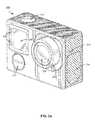
- FIG. 2 aillustrates a camera 200 for use with the camera systems described herein, according to one example embodiment.
- the camera 200is configured to capture images and video, and to store captured images and video for subsequent display or playback.
- the camera 200is adapted to fit within a camera housing, such as the housing 100 discussed above or any other housing described herein.
- the camera 200includes a lens 202 configured to receive light incident upon the lens and to direct received light onto an image sensor internal to the lens for capture by the image sensor.
- the lens 202is enclosed by a lens ring 204 .
- the camera 200can include various indicators, including the LED lights 206 and the LED display 208 shown in FIG. 2 a . When the camera 200 is enclosed within the housing 100 , the LED lights and the LED display 208 are configured to substantially align with the indicator window 106 and be visible through the housing 100 .
- the camera 200can also include buttons 210 configured to allow a user of the camera to interact with the camera, to turn the camera on, to initiate the capture of video or images, and to otherwise configure the operating mode of the camera.
- the camera 200can also include one or more microphones 212 configured to receive and record audio signals in conjunction with recording video.
- the camera 200includes one or more sets of microphones, with each set of microphones including a first microphone and a second, dampened microphone, where the second dampened microphone is configured to capture audio at approximately 20 dB (or any other suitable magnitude) less than the first microphone.
- the side of the camera 200includes an I/O interface 214 . Though the embodiment of FIG. 2 a illustrates the I/O interface 214 enclosed by a protective door, the I/O interface can include any type or number of I/O ports or mechanisms, such as USC ports, HDMI ports, memory card slots, and the like.
- FIG. 2 billustrates a perspective view of a rear of a camera 200 for use with the camera systems described herein, according to one embodiment.
- the camera 200includes a display 218 (such as an LCD or LED display) on the rear surface of the camera 200 .
- the display 218can be configured for use, for example, as an electronic view finder, to preview captured images or videos, or to perform any other suitable function.
- the camera 200also includes an expansion pack interface 220 configured to receive a removable expansion pack, such as an extra battery module, a wireless module, and the like. Removable expansion packs, when coupled to the camera 200 , provide additional functionality to the camera via the expansion pack interface 220 .
- FIG. 3is a block diagram illustrating electronic components of a camera, such as the camera 200 , according to one embodiment.
- the camera 200includes one or more microcontrollers 302 (such as a processor) that control the operation and functionality of the camera 200 .
- An image sensor 312captures light directed by the lens 202 to be incident upon the image sensor, and generates image data based on the light incident upon the image sensor at the time of capture.
- the microcontroller 302receives the image data generated by the image sensor 312 .
- a lens and focus controller 314is configured to control the operation and configuration of the camera lens 202 , for instance based on user input or based on analysis of captured image data.
- a system memory 304is configured to store executable computer instructions that, when executed by the microcontroller 302 , perform the camera functionalities described herein.
- the microcontroller 302 , the image sensor 312 , the lens 202 , and the lens and focus controller 314can be collectively referred to as an “image capturing module”.
- a synchronization engine 306is configured to synchronize the camera 200 with other cameras or with other external devices, such as a remote control, a second camera (such as a slave camera or master camera), an external controller, or a smartphone. Video clips and/or images captured by cameras that are synchronized can be aligned in post-processing, as described in greater detail with respect to FIGS. 4 through 5B .
- a controller hub 308transmits and receives information from user I/O components.
- the controller hub 308interfaces with the LED lights 206 , the display 208 , and the buttons 210 .
- the controller hub 308can interface with any conventional user I/O component or components.
- the controller hub 308may send information to other user I/O components, such as a speaker.
- a microphone controller 310receives and captures audio signals from one or more microphones 212 .
- the microphone controller 310is configured to control the operation of the microphones 212 .
- the microphone controller 310selects which microphones from which audio data is captured. For instance, for a camera 200 with multiple microphone pairs (each paid including a standard microphone and a dampened microphone), the microphone controller 310 selects one microphone of the pair to capture audio data.
- I/O port interface 214may facilitate the camera 200 in receiving or transmitting video or audio information through an I/O port.
- I/O ports or interfacesinclude USB ports, HDMI ports, Ethernet ports, audioports, and the like.
- embodiments of the I/O port interface 214may include wireless ports that can accommodate wireless connections. Examples of wireless ports include Bluetooth, Wireless USB, Near Field Communication (NFC), and the like.
- the expansion pack interface 220is configured to interface with camera add-ons and removable expansion packs, such as an extra battery module, a wireless module, and the like.
- FIG. 4is a block diagram illustrating a synchronization engine of a camera, according to one embodiment.
- the synchronization engine 306 of FIG. 4includes a transmission module 402 , a receiving module 404 , and a synchronization determination module 406 .
- the transmission module 402transmits a synchronization signal including a unique identifier (ID) identifying the camera (e.g., the camera 200 ).
- IDunique identifier
- the synchronization signal transmitted by the transmission module 402includes a current date and time of the camera (e.g., the camera 200 ).
- a transmission module 402can be configured to transmit synchronization signals anytime the camera is on, regardless of whether the camera is capturing images or videos.
- the transmission module 402is configured to transmit synchronization signals periodically (e.g., every one minute).
- the transmission module 402 of a slave devicein response to a synchronization signal received from a master device, transmits a corresponding synchronization signal.
- the synchronization signalsmay be based on various wireless communication protocols, such as, for example, Bluetooth, Wi-Fi such as IEEE 802.11, NFC, Zigbee, Ant+ protocol, WiFi Direct protocol, etc.
- the receiving module 404is configured to receive synchronization signals from one or more other devices.
- the received signalsinclude information such as the unique IDs of the one or more other devices as well as the current date and time of the one or more other devices when they transmit the synchronization signals.
- a devicecan discover the other devices using the signals received from one or more other devices.
- a devicecan pair with all the devices it has discovered.
- a devicepresents all the devices it has discovered to a user and pairs with only the devices selected by the user.
- when synchronization signals travel over limited distancesonly devices within a predetermined proximity can be paired. At a particular time point, a device may be paired with up to a predetermined number of other devices.
- Devices that are pairedcan be configured to actively communicate with each other. Note that devices that are paired can be synchronized, and can subsequently be unpaired. In other words, devices that are synchronized may move out of communicative range of each other—in such embodiments, the synchronized devices can still capture images and videos, can include synchronization labels with the captured images and videos, and the captured images and videos can be subsequently aligned in post-processing using the synchronization labels.
- the synchronization determination module 406determines synchronization information with one or more other devices.
- the synchronization informationcan be used to identify devices that are synchronized and to identify video frames or images that are captured substantially at the same time.
- the synchronization determination module 406provides the unique identifier of the device to the transmission module 402 and triggers the transmission module 402 to transmit synchronization signals including device information such as the unique identifier, the current date, or the current time at a particular time point.
- the synchronization determination module 406determines the synchronization information with the other device including a synchronization device label and a synchronization time label.
- the synchronization determination module 406further associates the determined synchronization information with the other device, including the synchronization device label and the synchronization time label, with one or more captured images or video frames.
- the synchronization device labelidentifies a pair of synchronized devices including a master device and a slave device.
- the synchronized devicesare those devices for which a temporal relationship has been established.
- the synchronization device labelrepresents the unique identifiers of the devices (i.e., the unique identifier transmitted by the transmission module 402 of a master device and the unique identifier received by the receiving module 404 of a slave device).
- the synchronization determination modules 406 of a master device and of a slave devicedetermine the synchronization device labels similarly such that the synchronization device labels determined by the master device and the slave device match.
- a master device's receiving module 404receives a synchronization signal transmitted by a slave device in response to receiving the synchronization signal transmitted by the master device.
- a slave device's transmission module 402transmits a synchronization signal in response to its receiving module 404 receiving a synchronization signal from a master device.
- a synchronization determination module 406determines the synchronization device label based on the unique identifiers of the master device and of the slave device. As one example, the synchronization determination module 406 determines the synchronization device label as a sum of hash values of the unique identifiers of a master device and of a slave device. As such, devices' privacy is protected as the devices' identifiers cannot be reversely determined from synchronization device labels. In other embodiments, the synchronization determination module 406 may determine the synchronization device label as a function of the unique identifiers of the devices.
- the synchronization device labels associated with two images or video frames captured by different devicesmatch, it can be determined (for instance, in post-processing) that the images or video frames are captured by devices that are synchronized.
- the temporal relationship between the devicescan also be established. That is, the relative timing between the video frames captured by the synchronized devices can be determined from a synchronization time label.
- the synchronization time labelindicates the relative timing between a pair of synchronized devices including a master device and a slave device.
- the synchronization determination module 406 of a master devicedetermines the synchronization time label as the difference between the current date and time of the master device and that of the slave device.
- the synchronization determination module 406 of a slave devicedetermines the synchronization time label as the difference between the current date and time of the slave device and that of the master device.
- the synchronization determination module 406 of the devicemay determine synchronization device labels and the synchronization time labels periodically based on the synchronization signals periodically transmitted by the transmission module 402 and the synchronization signals periodically received by the receiving module 404 from another device. For example, the synchronization determination module 406 of a device may determine the synchronization device label and the synchronization time label periodically when the transmission module 402 of the device transmits the synchronization signals. As another example, the receiving module 404 of a device provides device information such as the unique identifier, the current date, and the current time of another device to the synchronization determination module 406 upon receiving a synchronization signal from the other device.
- the synchronization determination module 406 of the devicedetermines the synchronization device label and the synchronization time label upon receiving the synchronization information from the receiving module 404 of the device.
- the synchronization determination module 406 of a deviceregularly obtains synchronization information such as the unique identifier, the current data, and the current time received from one or more other devices from the receiving module 404 and determines one or more synchronization device labels and synchronization time labels upon receiving the synchronization information from the receiving module 404 .
- the synchronization determination module 406 of a devicemodifies one or more video frames it captures with the synchronization device label and the synchronization time label.
- the synchronization determination module 406 of a deviceassociates the determined synchronization device label and synchronization time label with images and video captured by the device.
- the synchronization device label and synchronization time labelcan be included within image or video metadata (either within each video frame or within each video clip), in a table associating the synchronization information with captured images and videos, or
- the synchronization determination module 406may associate multiple synchronization device labels and synchronization time labels with a video frame the device captures when the device is paired with multiple other devices.
- the synchronization determination module 406may associate one or more video frames the device has captured or is about to capture with the determined synchronization device label and the synchronization time label. For a particular synchronization device label determined for a pair of synchronized devices, the synchronization determination module 406 of one device associates the synchronization time label with the video frames it captures until the synchronization time label is updated. In some embodiments, for a pair of synchronized devices with a particular synchronization device label, the devices update the synchronization time labels periodically to reduce the effect that various dynamic factors may have on synchronization time labels, thereby improving the accuracy of synchronization time labels. Exemplary dynamic factors include propagation delays, individual device clock drifting, or a relative distance change between the devices.
- a previous master devicebecomes the new slave device and a previous slave device becomes the new master device.
- Each devicecalculates an updated synchronization time label, and further compares the updated synchronization time label to the previous synchronization time label, beneficially enabling the devices to account for a processing lag by one of the devices that affects the generation of the synchronization time labels.
- the synchronization determination module 406associates the previous or the updated synchronization time label with the video frames captured by the device, depending on which synchronization time label is determined to represent a more accurate time differential between the devices.
- Temporal relationships between videos captured by different devicescan be established, for example, by using synchronization device and time labels. Video clips produced by different devices can thereby be aligned and edited in a single editing environment.
- Devices that are synchronizedcapture video frames associated with the same synchronization device label. That is, video frames associated with matching synchronization device labels are captured by devices that are synchronized.
- the temporal relationship between the video frames captured by the synchronized devicescan be determined according to the synchronization time label. That is, relative timing between the video frames or images captured by the synchronized devices can be determined and video frames or images that are captured substantially at the same time should be aligned.
- a deviceassociates its device identifier and a starting time point of a video clip with the video clip.
- a local time point when a video frame of the video clip is capturedcan be determined by using the starting time point of the video clip as well as the time period relative to the starting time point.
- the local time point of a first video frame captured by a master or slave devicecan be converted to a local time stamp of the slave or master device, respectively, according to the synchronization time label associated with the first video frame.
- the converted local time stamp of the slave or master deviceis used to identify a second video frame captured by the slave or master device substantially at the same time as the first video frame captured by the slave or master device, respectively.
- the video frames captured by the synchronized devices substantially at the same timecan be determined.
- temporal relationships between video clips captured by devices that are not pairedmay also be established. For instance, devices outside the predetermined proximity limited by the distance synchronization signals can travel cannot be paired. However, unpaired devices may be indirectly synchronized by other devices paired with those devices. For example, devices belonging to friends at opposite corners of a stadium watching a baseball game cannot be paired with each other but each of them can be paired with a common device belonging to a friend who is located in the middle of the stadium.
- a temporal relationship between video clips captured by a first and a second devicemay be established or inferred from an established temporal relationship between video clips captured by the first device and a third device, and an established temporal relationship between video clips captured by the second device and the third device.
- relative temporal relationships between the video clips captured by the unpaired devicesmay be established via the synchronization time labels established with a common device. Accordingly, in a single editing environment, video clips captured by unpaired devices can be aligned and accordingly edited. For example, video clips of an event captured by unpaired devices may be uploaded to a cloud service where editing based on the temporal relationships established between the unpaired devices and a common device is provided.
- FIG. 5Ais a sequence diagram illustrating a synchronization between cameras, according to one embodiment.
- a first device 502transmits a first synchronization signal 506 and initiates the synchronization process between the first device 502 and a second device 504 .
- the first synchronization signal 506includes device information such as the identifier as well as the current date and time of the first device 502 .
- the first synchronization signal 506may be received by one or more other devices within a predetermined proximity.
- the first device 502may transmit the first synchronization signal 506 periodically.
- the second device 504receives the first synchronization signal 506 and responds to the first device 502 with a second synchronization signal 508 .
- the second synchronization signal 508includes device information such as the identifier as well as the current date and time of the second device 504 .
- the first device 502determines 510 a synchronization device label and a synchronization time label based on its identifier and current date and time included in the first synchronization signal 506 and the second device's identifier and current and date and time included in the second synchronization signal 508 .
- the second device 504also determines 512 another synchronization device label and another synchronization time label based on the second device identifier and current date and time included in the second synchronization signal 508 as well as the first device's identifier and current date and time included in the first synchronization signal 506 .
- the first device 502 and the slave device 504may determine the synchronization device and time labels at the same time or at different times.
- the first device 502 and the second device 504may be paired and the synchronization device and time labels may be determined before or when one or both of the first and second devices 502 and 504 capture video or images.
- the first device 502associates 514 the determined synchronization device and time labels with video frames or images captured by the first device.
- the second device 504also associates 516 the determined synchronization device and time labels with video frames or images captured by the second device. Accordingly, the video frames or images captured by the first device 502 and the second device 504 can be aligned based on the synchronization device and time labels associated with each.
- the first and second devices 502 and 504After capturing images and/or video, the first and second devices 502 and 504 provide 518 and 520 the video clips or images, for example, to one or more users, to a cloud server, or to any other suitable device or entity.
- the video clips or imagesare associated with synchronization device and time labels and can be aligned as described with respect to FIG. 5B .
- FIG. 5Bis a flow diagram illustrating a method of aligning video clips and images, according to one embodiment.
- Video frames and/or images associated with synchronization device labels and synchronization time labels generated by the devices that captured the video frames and imagesare received 550 , for instance by a server, a desktop, or a mobile device.
- Usersmay upload video clips or images to the computing device, a storage device, or a cloud server, and can access the uploaded video clips or images with a media processing device (such as a computer or mobile device).
- a media processing devicesuch as a computer or mobile device.
- the media processing deviceidentifies 552 video frames or images that have matching synchronization device labels.
- Video frames or images having matching synchronization device labelsare captured by devices that are synchronized. That is, the temporal relationship between these video frames or images can be established using the synchronization time labels.
- the media processing deviceidentifies a first set of video frames from the first video clip and a second set of video frames from the second video clip. The first set of video frames and the second set of video frames each are associated with the same synchronization device label.
- the media processing deviceidentifies 554 the video frames or images that are captured at substantially the same time based on the synchronization time labels associated with the video frames. In other words, the media processing device identifies the video frames or images that are captured by a pair of synchronized devices at substantially the same time.
- the media processing deviceselects a first subset of video frames from the first set of video frames from the first video clip and identifies a first synchronization time label associated with the first subset of video frames.
- the media processing deviceselects a second subset of video frames from the second set of video frames based on the identified first synchronization time label and a second synchronization time label associated with the second subset of video frames.
- the first synchronization time label and the second synchronization time labelrepresent a substantially similar time difference.
- a local time point of a video framecan be determined based on a starting time point of the video clip including the video frame.
- the local time point of a first video frame captured at a first devicecan be converted to a corresponding local time point at the second device that is synchronized with the first device by adding or subtracting the time difference included within the synchronization time label corresponding to the second device.
- the media processing devicecan identify a second video frame captured by the second device based on the converted local time point at the second device.
- the second video frame and the first video frameare captured substantially at the same time. Accordingly, the media processing device can identify the video frames with matching synchronization device labels that are captured substantially at the same time.
- the media processing deviceorganizes 556 all video frames and images of the received video clips or images such that the video frames and images captured substantially at the same time are aligned. Accordingly, video frames and images that are captured by different devices at the same time can be correlated, combined into a single multi-camera video or set of images, and presented to a user of the media processing device, for instance via a hardware display.
- Coupledalong with its derivatives.
- the term “coupled” as used hereinis not necessarily limited to two or more elements being in direct physical or electrical contact. Rather, the term “coupled” may also encompass two or more elements are not in direct contact with each other, but yet still co-operate or interact with each other, or are structured to provide a thermal conduction path between the elements.
- the terms “comprises,” “comprising,” “includes,” “including,” “has,” “having” or any other variation thereof,are intended to cover a non-exclusive inclusion.
- a process, method, article, or apparatus that comprises a list of elementsis not necessarily limited to only those elements but may include other elements not expressly listed or inherent to such process, method, article, or apparatus.
- any reference to “one embodiment” or “an embodiment”means that a particular element, feature, structure, or characteristic described in connection with the embodiment is included in at least one embodiment.
- the appearances of the phrase “in one embodiment” in various places in the specificationare not necessarily all referring to the same embodiment.
Landscapes
- Engineering & Computer Science (AREA)
- Multimedia (AREA)
- Signal Processing (AREA)
- Studio Devices (AREA)
- Computer Security & Cryptography (AREA)
Abstract
Description
Claims (20)
Priority Applications (1)
| Application Number | Priority Date | Filing Date | Title |
|---|---|---|---|
| US14/951,482US9848132B2 (en) | 2015-11-24 | 2015-11-24 | Multi-camera time synchronization |
Applications Claiming Priority (1)
| Application Number | Priority Date | Filing Date | Title |
|---|---|---|---|
| US14/951,482US9848132B2 (en) | 2015-11-24 | 2015-11-24 | Multi-camera time synchronization |
Publications (2)
| Publication Number | Publication Date |
|---|---|
| US20170150236A1 US20170150236A1 (en) | 2017-05-25 |
| US9848132B2true US9848132B2 (en) | 2017-12-19 |
Family
ID=58721485
Family Applications (1)
| Application Number | Title | Priority Date | Filing Date |
|---|---|---|---|
| US14/951,482Active2035-12-23US9848132B2 (en) | 2015-11-24 | 2015-11-24 | Multi-camera time synchronization |
Country Status (1)
| Country | Link |
|---|---|
| US (1) | US9848132B2 (en) |
Cited By (1)
| Publication number | Priority date | Publication date | Assignee | Title |
|---|---|---|---|---|
| US10701317B2 (en) | 2016-03-31 | 2020-06-30 | Biton, Llc | Method for collective contribution video creation and messaging |
Families Citing this family (22)
| Publication number | Priority date | Publication date | Assignee | Title |
|---|---|---|---|---|
| USD830446S1 (en) | 2015-12-15 | 2018-10-09 | Gopro, Inc. | Multi-lens camera |
| USD861592S1 (en) | 2017-09-28 | 2019-10-01 | Gopro, Inc. | Battery |
| USD890835S1 (en) | 2017-12-28 | 2020-07-21 | Gopro, Inc. | Camera |
| US10972637B2 (en)* | 2018-03-13 | 2021-04-06 | Lyft, Inc. | Systems and methods for synchronizing sensor capture |
| USD907101S1 (en) | 2019-06-11 | 2021-01-05 | Gopro, Inc. | Camera |
| USD907680S1 (en) | 2018-08-31 | 2021-01-12 | Gopro, Inc. | Camera |
| USD903740S1 (en) | 2018-09-14 | 2020-12-01 | Gopro, Inc. | Camera |
| EP3824620A4 (en)* | 2018-10-25 | 2021-12-01 | Samsung Electronics Co., Ltd. | METHOD AND DEVICE FOR PROCESSING VIDEOS |
| CN113491083A (en)* | 2019-02-26 | 2021-10-08 | 松下知识产权经营株式会社 | Video camera image transmission/reproduction system, video camera constituting the system, and viewer |
| USD920419S1 (en) | 2019-09-17 | 2021-05-25 | Gopro, Inc. | Camera |
| USD1029745S1 (en) | 2019-09-13 | 2024-06-04 | Gopro, Inc. | Camera battery |
| US12066748B2 (en) | 2019-09-18 | 2024-08-20 | Gopro, Inc. | Door assemblies for image capture devices |
| DE212020000722U1 (en) | 2019-09-18 | 2022-04-26 | Gopro, Inc. | door assemblies for imaging devices |
| WO2022000417A1 (en) | 2020-07-02 | 2022-01-06 | Gopro, Inc. | Removable battery door assemblies for image capture devices |
| USD1029746S1 (en) | 2020-07-31 | 2024-06-04 | Gopro, Inc. | Battery |
| USD1050227S1 (en) | 2020-08-14 | 2024-11-05 | Gopro, Inc. | Camera door |
| USD946074S1 (en) | 2020-08-14 | 2022-03-15 | Gopro, Inc. | Camera |
| CN112261491B (en)* | 2020-12-22 | 2021-04-16 | 北京达佳互联信息技术有限公司 | Video time sequence marking method and device, electronic equipment and storage medium |
| USD1066462S1 (en) | 2021-02-12 | 2025-03-11 | Gopro, Inc. | Camera door |
| USD1061682S1 (en) | 2022-08-04 | 2025-02-11 | Gopro, Inc. | Camera door |
| US12321084B2 (en) | 2022-08-12 | 2025-06-03 | Gopro, Inc. | Interconnect mechanism for image capture device |
| US12321378B2 (en)* | 2023-09-07 | 2025-06-03 | International Business Machines Corporation | Ephemeral cloud for multi-perspective multimedia generation |
Citations (119)
| Publication number | Priority date | Publication date | Assignee | Title |
|---|---|---|---|---|
| US5260779A (en)* | 1992-02-21 | 1993-11-09 | Control Automation, Inc. | Method and apparatus for inspecting a printed circuit board |
| EP0605045A1 (en) | 1992-12-29 | 1994-07-06 | Laboratoires D'electronique Philips S.A.S. | Image processing method and apparatus for generating one image from adjacent images |
| EP0650299A1 (en) | 1993-10-20 | 1995-04-26 | Laboratoires D'electronique Philips S.A.S. | Image processing system comprising fixed cameras and a system simulating a moving camera |
| EP0661672A1 (en) | 1993-12-29 | 1995-07-05 | Laboratoires D'electronique Philips S.A.S. | Picture processing process and device for building a target image from a source image with perspective change |
| US5555895A (en)* | 1993-01-29 | 1996-09-17 | Centre National De La Recherche Scientifique | Process and device for eye movement analysis |
| US6434265B1 (en) | 1998-09-25 | 2002-08-13 | Apple Computers, Inc. | Aligning rectilinear images in 3D through projective registration and calibration |
| US20020112005A1 (en) | 1998-08-25 | 2002-08-15 | Charles Namias | Video e-mail kiosk |
| US20020122113A1 (en) | 1999-08-09 | 2002-09-05 | Foote Jonathan T. | Method and system for compensating for parallax in multiple camera systems |
| US6486908B1 (en) | 1998-05-27 | 2002-11-26 | Industrial Technology Research Institute | Image-based method and system for building spherical panoramas |
| US20020191087A1 (en) | 1996-04-15 | 2002-12-19 | Canon Kabushiki Kaisha | Communication apparatus and method that link a network address with designated image information |
| US20030085992A1 (en) | 2000-03-07 | 2003-05-08 | Sarnoff Corporation | Method and apparatus for providing immersive surveillance |
| US20030098954A1 (en)* | 2001-04-27 | 2003-05-29 | International Business Machines Corporation | Calibration-free eye gaze tracking |
| US20030160862A1 (en) | 2002-02-27 | 2003-08-28 | Charlier Michael L. | Apparatus having cooperating wide-angle digital camera system and microphone array |
| US20040010804A1 (en) | 1996-09-04 | 2004-01-15 | Hendricks John S. | Apparatus for video access and control over computer network, including image correction |
| US20040021780A1 (en) | 2002-07-31 | 2004-02-05 | Intel Corporation | Method and apparatus for automatic photograph annotation with contents of a camera's field of view |
| US20040047606A1 (en) | 2002-09-09 | 2004-03-11 | Canon Kabushiki Kaisha | Image recording apparatus capable of recording information associated with location upon image sensing together with sensed image data, and control method thereof |
| US6711293B1 (en) | 1999-03-08 | 2004-03-23 | The University Of British Columbia | Method and apparatus for identifying scale invariant features in an image and use of same for locating an object in an image |
| US6710740B2 (en) | 2002-03-04 | 2004-03-23 | Intel Corporation | Recording-location determination |
| US20040075738A1 (en) | 1999-05-12 | 2004-04-22 | Sean Burke | Spherical surveillance system architecture |
| US20040135900A1 (en) | 2003-01-15 | 2004-07-15 | Hewlett Packard Company | Method and apparatus for capture of sensory data in association with image data |
| US20040169724A1 (en) | 2002-12-09 | 2004-09-02 | Ekpar Frank Edughom | Method and apparatus for creating interactive virtual tours |
| US6788333B1 (en) | 2000-07-07 | 2004-09-07 | Microsoft Corporation | Panoramic video |
| US20050033760A1 (en) | 1998-09-01 | 2005-02-10 | Charles Fuller | Embedded metadata engines in digital capture devices |
| US20050062869A1 (en) | 1999-04-08 | 2005-03-24 | Zimmermann Steven Dwain | Immersive video presentations |
| US20050104976A1 (en) | 2003-11-17 | 2005-05-19 | Kevin Currans | System and method for applying inference information to digital camera metadata to identify digital picture content |
| US20050134707A1 (en) | 2003-12-18 | 2005-06-23 | Eastman Kodak Company | Image metadata attachment |
| US20050174435A1 (en)* | 2004-01-13 | 2005-08-11 | Sony Corporation | Imaging apparatus, phase control method, and synchronization method |
| US20050289111A1 (en) | 2004-06-25 | 2005-12-29 | Tribble Guy L | Method and apparatus for processing metadata |
| US20060050997A1 (en) | 2004-09-09 | 2006-03-09 | Casio Computer Co., Ltd. | Camera device with movie capture function |
| US7057663B1 (en)* | 2001-05-17 | 2006-06-06 | Be Here Corporation | Audio synchronization pulse for multi-camera capture systems |
| US20070030358A1 (en) | 2005-07-19 | 2007-02-08 | Canon Kabushiki Kaisha | Image-processing device, method for controlling same, computer program, and storage medium |
| US20070053659A1 (en)* | 2003-10-10 | 2007-03-08 | Jiro Kiyama | Reproducing apparatus, method for controlling reproducing apparatus, content recording medium, data structure, control program, computer-readable recording medium storing control program |
| US20070120986A1 (en) | 2005-11-08 | 2007-05-31 | Takashi Nunomaki | Imaging device, information processing method, and computer program |
| US20070140662A1 (en) | 2005-11-08 | 2007-06-21 | Takashi Nunomaki | Information processing apparatus, imaging device, information processing method, and computer program |
| US20070300249A1 (en)* | 2006-06-22 | 2007-12-27 | Smith Kevin P | In-band data recognition and synchronization system |
| US20080094499A1 (en) | 2005-12-07 | 2008-04-24 | Sony Corporation | Imaging apparatus, data recording method and data-display control method, and computer program |
| US20080118100A1 (en) | 2006-11-20 | 2008-05-22 | Canon Kabushiki Kaisha | Information processing apparatus and control method thereof, and computer readable storage medium |
| WO2009047572A1 (en) | 2007-10-09 | 2009-04-16 | Analysis Systems Research High-Tech S.A. | Integrated system, method and application for the synchronized interactive play-back of multiple spherical video content and autonomous product for the interactive play-back of prerecorded events. |
| US20090210707A1 (en)* | 2006-05-15 | 2009-08-20 | Paolo De Lutiis | Out-of Band Authentication Method and System for Communication Over a Data Network |
| US20090251558A1 (en) | 2008-04-04 | 2009-10-08 | Samsung Techwin Co., Ltd. | Fast and low-power digital camera with gps |
| US20090262206A1 (en) | 2008-04-16 | 2009-10-22 | Johnson Controls Technology Company | Systems and methods for providing immersive displays of video camera information from a plurality of cameras |
| US20090271447A1 (en)* | 2008-04-28 | 2009-10-29 | Shin Kang Soo | Method for synchronizing contents file and device for employing the same |
| US20100045773A1 (en) | 2007-11-06 | 2010-02-25 | Ritchey Kurtis J | Panoramic adapter system and method with spherical field-of-view coverage |
| US20100097443A1 (en) | 2008-10-16 | 2010-04-22 | Peter Lablans | Controller in a Camera for Creating a Panoramic Image |
| US20100238304A1 (en) | 2009-03-18 | 2010-09-23 | Casio Computer Co., Ltd. | Digital camera for recording still image with speech |
| US20100250022A1 (en) | 2006-12-29 | 2010-09-30 | Air Recon, Inc. | Useful unmanned aerial vehicle |
| US20100289924A1 (en) | 2009-05-14 | 2010-11-18 | Hoya Corporation | Imager that adds visual effects to an image |
| US20100299630A1 (en) | 2009-05-22 | 2010-11-25 | Immersive Media Company | Hybrid media viewing application including a region of interest within a wide field of view |
| US20110013778A1 (en) | 2004-06-23 | 2011-01-20 | Yamaha Corporation | Speaker array apparatus and method for setting audio beams of speaker array appratus |
| US20110115883A1 (en) | 2009-11-16 | 2011-05-19 | Marcus Kellerman | Method And System For Adaptive Viewport For A Mobile Device Based On Viewing Angle |
| US20110141300A1 (en) | 2009-12-11 | 2011-06-16 | Fotonation Ireland Limited | Panorama Imaging Using a Blending Map |
| US7983502B2 (en) | 2007-08-06 | 2011-07-19 | Microsoft Corporation | Viewing wide angle images using dynamic tone mapping |
| US20110261227A1 (en) | 2008-09-12 | 2011-10-27 | Nikon Corporation | Imaging apparatus |
| US20120206565A1 (en) | 2011-02-10 | 2012-08-16 | Jason Villmer | Omni-directional camera and related viewing software |
| US20120242798A1 (en) | 2011-01-10 | 2012-09-27 | Terrence Edward Mcardle | System and method for sharing virtual and augmented reality scenes between users and viewers |
| US20130021450A1 (en)* | 2011-07-22 | 2013-01-24 | Yasuo Yoshizawa | Stereoscopic imaging system, recording control method, stereoscopic image reproduction system, and reproduction control method |
| US20130058619A1 (en) | 2011-09-02 | 2013-03-07 | Nikon Corporation | Imaging device and image-audio playback device |
| US20130058532A1 (en) | 2007-03-05 | 2013-03-07 | Sportvision, Inc. | Tracking An Object With Multiple Asynchronous Cameras |
| US20130127903A1 (en) | 2009-02-26 | 2013-05-23 | Sylvain Paris | System and Method for Reducing the Appearance of Residuals in Gradient-Based Image Compositing |
| US20130176403A1 (en) | 2011-08-16 | 2013-07-11 | Kenneth Varga | Heads up display (HUD) sensor system |
| US20130177168A1 (en) | 2009-12-24 | 2013-07-11 | Nokia Corporation | Apparatus |
| US20130182177A1 (en) | 2012-01-18 | 2013-07-18 | John Furlan | Systems and methods for improving video stutter in high resolution progressive video |
| US20130210563A1 (en) | 2009-05-02 | 2013-08-15 | Steven J. Hollinger | Ball with camera for reconnaissance or recreation and network for operating the same |
| US20130235226A1 (en) | 2012-03-12 | 2013-09-12 | Keith Stoll Karn | Digital camera having low power capture mode |
| US8606073B2 (en) | 2010-05-12 | 2013-12-10 | Woodman Labs, Inc. | Broadcast management system |
| US20140039884A1 (en) | 2001-12-14 | 2014-02-06 | Microsoft Corporation | Quality improvement techniques in an audio encoder |
| US20140037268A1 (en) | 2012-08-03 | 2014-02-06 | Canon Kabushiki Kaisha | Moving image recording apparatus capable of recording moving images to recording media, and control method and storage medium therefor |
| US8670030B2 (en) | 2010-05-25 | 2014-03-11 | Olympus Imaging Corp. | Photographing device and control method therefor |
| WO2014090277A1 (en) | 2012-12-10 | 2014-06-19 | Nokia Corporation | Spatial audio apparatus |
| US8793332B2 (en)* | 2009-07-21 | 2014-07-29 | Apple Inc. | Content tagging using broadcast device information |
| US20140240122A1 (en) | 2014-02-27 | 2014-08-28 | Fitbit, Inc. | Notifications on a User Device Based on Activity Detected By an Activity Monitoring Device |
| US8842197B2 (en) | 2005-11-30 | 2014-09-23 | Scenera Mobile Technologies, Llc | Automatic generation of metadata for a digital image based on ambient conditions |
| US8890954B2 (en) | 2010-09-13 | 2014-11-18 | Contour, Llc | Portable digital video camera configured for remote image acquisition control and viewing |
| US20150055937A1 (en) | 2013-08-21 | 2015-02-26 | Jaunt Inc. | Aggregating images and audio data to generate virtual reality content |
| US9019396B2 (en) | 2012-04-19 | 2015-04-28 | Olympus Corporation | Wireless communication device, memory device, wireless communication system, wireless communication method, and program recordable medium |
| US20150142211A1 (en) | 2012-05-04 | 2015-05-21 | Aeryon Labs Inc. | System and method for controlling unmanned aerial vehicles |
| US20150142742A1 (en)* | 2013-11-17 | 2015-05-21 | Zhen-Chao HONG | System and method for syncing local directories that enable file access across multiple devices |
| US20150166476A1 (en) | 2013-12-17 | 2015-06-18 | Yi-Cheng Chen | Methods for treating neurodegenerative diseases associated with aggregation of amyloid-beta |
| US20150186073A1 (en) | 2013-12-30 | 2015-07-02 | Lyve Minds, Inc. | Integration of a device with a storage network |
| US20150189221A1 (en) | 2013-12-26 | 2015-07-02 | Canon Kabushiki Kaisha | Image reproducing apparatus and method for controlling same |
| US9129640B2 (en)* | 2012-12-12 | 2015-09-08 | Crowdflik, Inc. | Collaborative digital video platform that enables synchronized capture, curation and editing of multiple user-generated videos |
| US20150288754A1 (en)* | 2014-04-07 | 2015-10-08 | Palo Alto Research Center Incorporated | Service discovery using collection synchronization with exact names |
| US20150287435A1 (en) | 2014-04-04 | 2015-10-08 | Red.Com, Inc. | Video camera with capture modes |
| US9158304B2 (en) | 2013-11-10 | 2015-10-13 | Google Inc. | Methods and systems for alerting and aiding an emergency situation |
| US20150304532A1 (en) | 2014-04-18 | 2015-10-22 | Alarm.Com Incorporated | Pan and tilt camera with robotic movement |
| US20150336015A1 (en) | 2014-05-21 | 2015-11-26 | Universal City Studios Llc | Ride vehicle tracking and control system using passive tracking elements |
| US20150339301A1 (en)* | 2014-05-20 | 2015-11-26 | Syn Holdings LLC | Methods and systems for media synchronization |
| US20150350614A1 (en) | 2012-08-31 | 2015-12-03 | Brain Corporation | Apparatus and methods for tracking using aerial video |
| US20150348591A1 (en)* | 2010-08-26 | 2015-12-03 | Blast Motion Inc. | Sensor and media event detection system |
| US20150363648A1 (en) | 2014-06-11 | 2015-12-17 | Arris Enterprises, Inc. | Detection of demarcating segments in video |
| US20150367958A1 (en) | 2014-06-20 | 2015-12-24 | nearmap australia pty ltd. | Wide-area aerial camera systems |
| US20150370250A1 (en) | 2014-06-19 | 2015-12-24 | Skydio, Inc. | Magic wand interface and other user interaction paradigms for a flying digital assistant |
| US20160005435A1 (en) | 2014-07-03 | 2016-01-07 | Gopro, Inc. | Automatic generation of video and directional audio from spherical content |
| US20160018822A1 (en) | 2014-07-18 | 2016-01-21 | Helico Aerospace Industries Sia | Autonomous vehicle operation |
| US20160031559A1 (en) | 2014-07-30 | 2016-02-04 | SZ DJI Technology Co., Ltd | Systems and methods for target tracking |
| US20160054737A1 (en) | 2014-08-22 | 2016-02-25 | Cape Productions Inc. | Methods and Apparatus for Unmanned Aerial Vehicle Autonomous Aviation |
| US20160069131A1 (en)* | 2014-09-08 | 2016-03-10 | Hunter Douglas Industries Switzerland Gmbh | Actuating device, especially for a shading system, for actuation with a string element |
| US20160076892A1 (en) | 2014-03-24 | 2016-03-17 | SZ DJI Technology Co., Ltd | Methods and systems for determining a state of an unmanned aerial vehicle |
| US20160098469A1 (en)* | 2014-10-07 | 2016-04-07 | Yahoo! Inc. | Method and system for providing a synchronization service |
| US20160101856A1 (en) | 2014-06-23 | 2016-04-14 | Nixie Labs, Inc. | Wearable unmanned aerial vehicles, and associated systems and methods |
| US20160112713A1 (en) | 2014-10-20 | 2016-04-21 | Google Inc. | Mapping spherical image to 2d representations |
| US20160117553A1 (en)* | 2013-06-07 | 2016-04-28 | Zte Corporation | Method, device and system for realizing visual identification |
| US20160129999A1 (en) | 2014-11-07 | 2016-05-12 | Paccar Inc | Drone systems for pre-trip inspection and assisted backing |
| US20160139596A1 (en) | 2014-11-14 | 2016-05-19 | Lg Electronics Inc. | Mobile terminal and controlling method thereof |
| US20160165563A1 (en)* | 2013-07-31 | 2016-06-09 | Samsung Electronics Co., Ltd. | Method and apparatus for time synchronization in device-to-device communication |
| US20160179096A1 (en) | 2014-05-23 | 2016-06-23 | Lily Robotics, Inc. | Launching unmanned aerial copter from mid-air |
| US20160189101A1 (en) | 2014-05-20 | 2016-06-30 | Verizon Patent And Licensing Inc. | Secure payload deliveries via unmanned aerial vehicles |
| US20160234438A1 (en) | 2015-02-06 | 2016-08-11 | Tetsuya Satoh | Image processing system, image generation apparatus, and image generation method |
| US20160239340A1 (en) | 2015-02-13 | 2016-08-18 | International Business Machines Corporation | Determining an ordering to use to open and close programs that call other programs |
| US20160269621A1 (en) | 2015-03-13 | 2016-09-15 | Center For Integrated Smart Sensors Foundation | Front-end event detector and low-power camera system using thereof |
| US20160295108A1 (en) | 2015-04-01 | 2016-10-06 | Cheng Cao | System and method for panoramic imaging |
| US9473758B1 (en) | 2015-12-06 | 2016-10-18 | Sliver VR Technologies, Inc. | Methods and systems for game video recording and virtual reality replay |
| US20160306351A1 (en) | 2015-04-14 | 2016-10-20 | Vantage Robotics, Llc | System for authoring, executing, and distributing unmanned aerial vehicle flight-behavior profiles |
| US20160304198A1 (en) | 2014-12-03 | 2016-10-20 | Google Inc. | Systems and methods for reliable relative navigation and autonomous following between unmanned aerial vehicle and a target object |
| US20160313734A1 (en) | 2015-04-21 | 2016-10-27 | Gopro, Inc. | Return Path Configuration For Remote Controlled Aerial Vehicle |
| US20160327950A1 (en) | 2014-06-19 | 2016-11-10 | Skydio, Inc. | Virtual camera interface and other user interaction paradigms for a flying digital assistant |
| US20160336020A1 (en) | 2015-05-11 | 2016-11-17 | Lily Robotics, Inc. | External microphone for an unmanned aerial vehicle |
| US20160366290A1 (en) | 2015-06-11 | 2016-12-15 | Casio Computer Co., Ltd. | Image shooting apparatus for adding information to image |
| US9602795B1 (en) | 2016-02-22 | 2017-03-21 | Gopro, Inc. | System and method for presenting and viewing a spherical video segment |
- 2015
- 2015-11-24USUS14/951,482patent/US9848132B2/enactiveActive
Patent Citations (126)
| Publication number | Priority date | Publication date | Assignee | Title |
|---|---|---|---|---|
| US5260779A (en)* | 1992-02-21 | 1993-11-09 | Control Automation, Inc. | Method and apparatus for inspecting a printed circuit board |
| EP0605045A1 (en) | 1992-12-29 | 1994-07-06 | Laboratoires D'electronique Philips S.A.S. | Image processing method and apparatus for generating one image from adjacent images |
| US5555895A (en)* | 1993-01-29 | 1996-09-17 | Centre National De La Recherche Scientifique | Process and device for eye movement analysis |
| EP0650299A1 (en) | 1993-10-20 | 1995-04-26 | Laboratoires D'electronique Philips S.A.S. | Image processing system comprising fixed cameras and a system simulating a moving camera |
| EP0661672A1 (en) | 1993-12-29 | 1995-07-05 | Laboratoires D'electronique Philips S.A.S. | Picture processing process and device for building a target image from a source image with perspective change |
| US20020191087A1 (en) | 1996-04-15 | 2002-12-19 | Canon Kabushiki Kaisha | Communication apparatus and method that link a network address with designated image information |
| US20040010804A1 (en) | 1996-09-04 | 2004-01-15 | Hendricks John S. | Apparatus for video access and control over computer network, including image correction |
| US6486908B1 (en) | 1998-05-27 | 2002-11-26 | Industrial Technology Research Institute | Image-based method and system for building spherical panoramas |
| US20020112005A1 (en) | 1998-08-25 | 2002-08-15 | Charles Namias | Video e-mail kiosk |
| US7403224B2 (en) | 1998-09-01 | 2008-07-22 | Virage, Inc. | Embedded metadata engines in digital capture devices |
| US20050033760A1 (en) | 1998-09-01 | 2005-02-10 | Charles Fuller | Embedded metadata engines in digital capture devices |
| US6434265B1 (en) | 1998-09-25 | 2002-08-13 | Apple Computers, Inc. | Aligning rectilinear images in 3D through projective registration and calibration |
| US6711293B1 (en) | 1999-03-08 | 2004-03-23 | The University Of British Columbia | Method and apparatus for identifying scale invariant features in an image and use of same for locating an object in an image |
| US20050062869A1 (en) | 1999-04-08 | 2005-03-24 | Zimmermann Steven Dwain | Immersive video presentations |
| US20040075738A1 (en) | 1999-05-12 | 2004-04-22 | Sean Burke | Spherical surveillance system architecture |
| US20020122113A1 (en) | 1999-08-09 | 2002-09-05 | Foote Jonathan T. | Method and system for compensating for parallax in multiple camera systems |
| US20030085992A1 (en) | 2000-03-07 | 2003-05-08 | Sarnoff Corporation | Method and apparatus for providing immersive surveillance |
| US6788333B1 (en) | 2000-07-07 | 2004-09-07 | Microsoft Corporation | Panoramic video |
| US20030098954A1 (en)* | 2001-04-27 | 2003-05-29 | International Business Machines Corporation | Calibration-free eye gaze tracking |
| US7057663B1 (en)* | 2001-05-17 | 2006-06-06 | Be Here Corporation | Audio synchronization pulse for multi-camera capture systems |
| US20140039884A1 (en) | 2001-12-14 | 2014-02-06 | Microsoft Corporation | Quality improvement techniques in an audio encoder |
| US20030160862A1 (en) | 2002-02-27 | 2003-08-28 | Charlier Michael L. | Apparatus having cooperating wide-angle digital camera system and microphone array |
| US6710740B2 (en) | 2002-03-04 | 2004-03-23 | Intel Corporation | Recording-location determination |
| US20040021780A1 (en) | 2002-07-31 | 2004-02-05 | Intel Corporation | Method and apparatus for automatic photograph annotation with contents of a camera's field of view |
| US20040047606A1 (en) | 2002-09-09 | 2004-03-11 | Canon Kabushiki Kaisha | Image recording apparatus capable of recording information associated with location upon image sensing together with sensed image data, and control method thereof |
| US20040169724A1 (en) | 2002-12-09 | 2004-09-02 | Ekpar Frank Edughom | Method and apparatus for creating interactive virtual tours |
| US20040135900A1 (en) | 2003-01-15 | 2004-07-15 | Hewlett Packard Company | Method and apparatus for capture of sensory data in association with image data |
| US20070053659A1 (en)* | 2003-10-10 | 2007-03-08 | Jiro Kiyama | Reproducing apparatus, method for controlling reproducing apparatus, content recording medium, data structure, control program, computer-readable recording medium storing control program |
| US20050104976A1 (en) | 2003-11-17 | 2005-05-19 | Kevin Currans | System and method for applying inference information to digital camera metadata to identify digital picture content |
| US20050134707A1 (en) | 2003-12-18 | 2005-06-23 | Eastman Kodak Company | Image metadata attachment |
| US20050174435A1 (en)* | 2004-01-13 | 2005-08-11 | Sony Corporation | Imaging apparatus, phase control method, and synchronization method |
| US20110013778A1 (en) | 2004-06-23 | 2011-01-20 | Yamaha Corporation | Speaker array apparatus and method for setting audio beams of speaker array appratus |
| US20050289111A1 (en) | 2004-06-25 | 2005-12-29 | Tribble Guy L | Method and apparatus for processing metadata |
| US20060050997A1 (en) | 2004-09-09 | 2006-03-09 | Casio Computer Co., Ltd. | Camera device with movie capture function |
| US20070030358A1 (en) | 2005-07-19 | 2007-02-08 | Canon Kabushiki Kaisha | Image-processing device, method for controlling same, computer program, and storage medium |
| US20070140662A1 (en) | 2005-11-08 | 2007-06-21 | Takashi Nunomaki | Information processing apparatus, imaging device, information processing method, and computer program |
| US20070120986A1 (en) | 2005-11-08 | 2007-05-31 | Takashi Nunomaki | Imaging device, information processing method, and computer program |
| US8842197B2 (en) | 2005-11-30 | 2014-09-23 | Scenera Mobile Technologies, Llc | Automatic generation of metadata for a digital image based on ambient conditions |
| US9342534B2 (en) | 2005-11-30 | 2016-05-17 | Scenera Mobile Technologies, Llc | Automatic generation of metadata for a digital image based on meterological conditions |
| US20080094499A1 (en) | 2005-12-07 | 2008-04-24 | Sony Corporation | Imaging apparatus, data recording method and data-display control method, and computer program |
| US20090210707A1 (en)* | 2006-05-15 | 2009-08-20 | Paolo De Lutiis | Out-of Band Authentication Method and System for Communication Over a Data Network |
| US20070300249A1 (en)* | 2006-06-22 | 2007-12-27 | Smith Kevin P | In-band data recognition and synchronization system |
| US20080118100A1 (en) | 2006-11-20 | 2008-05-22 | Canon Kabushiki Kaisha | Information processing apparatus and control method thereof, and computer readable storage medium |
| US20100250022A1 (en) | 2006-12-29 | 2010-09-30 | Air Recon, Inc. | Useful unmanned aerial vehicle |
| US20130058532A1 (en) | 2007-03-05 | 2013-03-07 | Sportvision, Inc. | Tracking An Object With Multiple Asynchronous Cameras |
| US7983502B2 (en) | 2007-08-06 | 2011-07-19 | Microsoft Corporation | Viewing wide angle images using dynamic tone mapping |
| WO2009047572A1 (en) | 2007-10-09 | 2009-04-16 | Analysis Systems Research High-Tech S.A. | Integrated system, method and application for the synchronized interactive play-back of multiple spherical video content and autonomous product for the interactive play-back of prerecorded events. |
| US20100045773A1 (en) | 2007-11-06 | 2010-02-25 | Ritchey Kurtis J | Panoramic adapter system and method with spherical field-of-view coverage |
| US20090251558A1 (en) | 2008-04-04 | 2009-10-08 | Samsung Techwin Co., Ltd. | Fast and low-power digital camera with gps |
| US20090262206A1 (en) | 2008-04-16 | 2009-10-22 | Johnson Controls Technology Company | Systems and methods for providing immersive displays of video camera information from a plurality of cameras |
| US20090271447A1 (en)* | 2008-04-28 | 2009-10-29 | Shin Kang Soo | Method for synchronizing contents file and device for employing the same |
| US20110261227A1 (en) | 2008-09-12 | 2011-10-27 | Nikon Corporation | Imaging apparatus |
| US20100097443A1 (en) | 2008-10-16 | 2010-04-22 | Peter Lablans | Controller in a Camera for Creating a Panoramic Image |
| US20130127903A1 (en) | 2009-02-26 | 2013-05-23 | Sylvain Paris | System and Method for Reducing the Appearance of Residuals in Gradient-Based Image Compositing |
| US20100238304A1 (en) | 2009-03-18 | 2010-09-23 | Casio Computer Co., Ltd. | Digital camera for recording still image with speech |
| US8411166B2 (en) | 2009-03-18 | 2013-04-02 | Casio Computer Co., Ltd. | Digital camera for recording still image with speech |
| US20130210563A1 (en) | 2009-05-02 | 2013-08-15 | Steven J. Hollinger | Ball with camera for reconnaissance or recreation and network for operating the same |
| US20100289924A1 (en) | 2009-05-14 | 2010-11-18 | Hoya Corporation | Imager that adds visual effects to an image |
| US20100299630A1 (en) | 2009-05-22 | 2010-11-25 | Immersive Media Company | Hybrid media viewing application including a region of interest within a wide field of view |
| US8793332B2 (en)* | 2009-07-21 | 2014-07-29 | Apple Inc. | Content tagging using broadcast device information |
| US20110115883A1 (en) | 2009-11-16 | 2011-05-19 | Marcus Kellerman | Method And System For Adaptive Viewport For A Mobile Device Based On Viewing Angle |
| US20110141300A1 (en) | 2009-12-11 | 2011-06-16 | Fotonation Ireland Limited | Panorama Imaging Using a Blending Map |
| US20130177168A1 (en) | 2009-12-24 | 2013-07-11 | Nokia Corporation | Apparatus |
| US8606073B2 (en) | 2010-05-12 | 2013-12-10 | Woodman Labs, Inc. | Broadcast management system |
| US8670030B2 (en) | 2010-05-25 | 2014-03-11 | Olympus Imaging Corp. | Photographing device and control method therefor |
| US20150348591A1 (en)* | 2010-08-26 | 2015-12-03 | Blast Motion Inc. | Sensor and media event detection system |
| US8896694B2 (en) | 2010-09-13 | 2014-11-25 | Contour, Llc | Portable digital video camera configured for remote image acquisition control and viewing |
| US8890954B2 (en) | 2010-09-13 | 2014-11-18 | Contour, Llc | Portable digital video camera configured for remote image acquisition control and viewing |
| US20120242798A1 (en) | 2011-01-10 | 2012-09-27 | Terrence Edward Mcardle | System and method for sharing virtual and augmented reality scenes between users and viewers |
| US20120206565A1 (en) | 2011-02-10 | 2012-08-16 | Jason Villmer | Omni-directional camera and related viewing software |
| US20130021450A1 (en)* | 2011-07-22 | 2013-01-24 | Yasuo Yoshizawa | Stereoscopic imaging system, recording control method, stereoscopic image reproduction system, and reproduction control method |
| US20130176403A1 (en) | 2011-08-16 | 2013-07-11 | Kenneth Varga | Heads up display (HUD) sensor system |
| US20130058619A1 (en) | 2011-09-02 | 2013-03-07 | Nikon Corporation | Imaging device and image-audio playback device |
| US20130182177A1 (en) | 2012-01-18 | 2013-07-18 | John Furlan | Systems and methods for improving video stutter in high resolution progressive video |
| US20130235226A1 (en) | 2012-03-12 | 2013-09-12 | Keith Stoll Karn | Digital camera having low power capture mode |
| US9019396B2 (en) | 2012-04-19 | 2015-04-28 | Olympus Corporation | Wireless communication device, memory device, wireless communication system, wireless communication method, and program recordable medium |
| US20150142211A1 (en) | 2012-05-04 | 2015-05-21 | Aeryon Labs Inc. | System and method for controlling unmanned aerial vehicles |
| US20140037268A1 (en) | 2012-08-03 | 2014-02-06 | Canon Kabushiki Kaisha | Moving image recording apparatus capable of recording moving images to recording media, and control method and storage medium therefor |
| US20150350614A1 (en) | 2012-08-31 | 2015-12-03 | Brain Corporation | Apparatus and methods for tracking using aerial video |
| WO2014090277A1 (en) | 2012-12-10 | 2014-06-19 | Nokia Corporation | Spatial audio apparatus |
| US9129640B2 (en)* | 2012-12-12 | 2015-09-08 | Crowdflik, Inc. | Collaborative digital video platform that enables synchronized capture, curation and editing of multiple user-generated videos |
| US20160117553A1 (en)* | 2013-06-07 | 2016-04-28 | Zte Corporation | Method, device and system for realizing visual identification |
| US20160165563A1 (en)* | 2013-07-31 | 2016-06-09 | Samsung Electronics Co., Ltd. | Method and apparatus for time synchronization in device-to-device communication |
| US20150055937A1 (en) | 2013-08-21 | 2015-02-26 | Jaunt Inc. | Aggregating images and audio data to generate virtual reality content |
| US20150058102A1 (en) | 2013-08-21 | 2015-02-26 | Jaunt Inc. | Generating content for a virtual reality system |
| US9158304B2 (en) | 2013-11-10 | 2015-10-13 | Google Inc. | Methods and systems for alerting and aiding an emergency situation |
| US9409646B2 (en) | 2013-11-10 | 2016-08-09 | Google Inc. | Methods and systems for providing aerial assistance |
| US20150142742A1 (en)* | 2013-11-17 | 2015-05-21 | Zhen-Chao HONG | System and method for syncing local directories that enable file access across multiple devices |
| US20150166476A1 (en) | 2013-12-17 | 2015-06-18 | Yi-Cheng Chen | Methods for treating neurodegenerative diseases associated with aggregation of amyloid-beta |
| US20150189221A1 (en) | 2013-12-26 | 2015-07-02 | Canon Kabushiki Kaisha | Image reproducing apparatus and method for controlling same |
| US20150186073A1 (en) | 2013-12-30 | 2015-07-02 | Lyve Minds, Inc. | Integration of a device with a storage network |
| US20140240122A1 (en) | 2014-02-27 | 2014-08-28 | Fitbit, Inc. | Notifications on a User Device Based on Activity Detected By an Activity Monitoring Device |
| US20160076892A1 (en) | 2014-03-24 | 2016-03-17 | SZ DJI Technology Co., Ltd | Methods and systems for determining a state of an unmanned aerial vehicle |
| US20150287435A1 (en) | 2014-04-04 | 2015-10-08 | Red.Com, Inc. | Video camera with capture modes |
| US20150288754A1 (en)* | 2014-04-07 | 2015-10-08 | Palo Alto Research Center Incorporated | Service discovery using collection synchronization with exact names |
| US20150304532A1 (en) | 2014-04-18 | 2015-10-22 | Alarm.Com Incorporated | Pan and tilt camera with robotic movement |
| US20160189101A1 (en) | 2014-05-20 | 2016-06-30 | Verizon Patent And Licensing Inc. | Secure payload deliveries via unmanned aerial vehicles |
| US20150339301A1 (en)* | 2014-05-20 | 2015-11-26 | Syn Holdings LLC | Methods and systems for media synchronization |
| US20150336015A1 (en) | 2014-05-21 | 2015-11-26 | Universal City Studios Llc | Ride vehicle tracking and control system using passive tracking elements |
| US20160179096A1 (en) | 2014-05-23 | 2016-06-23 | Lily Robotics, Inc. | Launching unmanned aerial copter from mid-air |
| US20150363648A1 (en) | 2014-06-11 | 2015-12-17 | Arris Enterprises, Inc. | Detection of demarcating segments in video |
| US20150370250A1 (en) | 2014-06-19 | 2015-12-24 | Skydio, Inc. | Magic wand interface and other user interaction paradigms for a flying digital assistant |
| US20160327950A1 (en) | 2014-06-19 | 2016-11-10 | Skydio, Inc. | Virtual camera interface and other user interaction paradigms for a flying digital assistant |
| US20150367958A1 (en) | 2014-06-20 | 2015-12-24 | nearmap australia pty ltd. | Wide-area aerial camera systems |
| US20160101856A1 (en) | 2014-06-23 | 2016-04-14 | Nixie Labs, Inc. | Wearable unmanned aerial vehicles, and associated systems and methods |
| US20160139602A1 (en) | 2014-06-23 | 2016-05-19 | Nixie Labs, Inc. | Launch-controlled unmanned aerial vehicles, and associated systems and methods |
| US20160005435A1 (en) | 2014-07-03 | 2016-01-07 | Gopro, Inc. | Automatic generation of video and directional audio from spherical content |
| US20160018822A1 (en) | 2014-07-18 | 2016-01-21 | Helico Aerospace Industries Sia | Autonomous vehicle operation |
| US20160031559A1 (en) | 2014-07-30 | 2016-02-04 | SZ DJI Technology Co., Ltd | Systems and methods for target tracking |
| US20160054737A1 (en) | 2014-08-22 | 2016-02-25 | Cape Productions Inc. | Methods and Apparatus for Unmanned Aerial Vehicle Autonomous Aviation |
| US20160069131A1 (en)* | 2014-09-08 | 2016-03-10 | Hunter Douglas Industries Switzerland Gmbh | Actuating device, especially for a shading system, for actuation with a string element |
| US20160098469A1 (en)* | 2014-10-07 | 2016-04-07 | Yahoo! Inc. | Method and system for providing a synchronization service |
| US20160112713A1 (en) | 2014-10-20 | 2016-04-21 | Google Inc. | Mapping spherical image to 2d representations |
| US20160129999A1 (en) | 2014-11-07 | 2016-05-12 | Paccar Inc | Drone systems for pre-trip inspection and assisted backing |
| US20160139596A1 (en) | 2014-11-14 | 2016-05-19 | Lg Electronics Inc. | Mobile terminal and controlling method thereof |
| US20160304198A1 (en) | 2014-12-03 | 2016-10-20 | Google Inc. | Systems and methods for reliable relative navigation and autonomous following between unmanned aerial vehicle and a target object |
| US20160234438A1 (en) | 2015-02-06 | 2016-08-11 | Tetsuya Satoh | Image processing system, image generation apparatus, and image generation method |
| US20160239340A1 (en) | 2015-02-13 | 2016-08-18 | International Business Machines Corporation | Determining an ordering to use to open and close programs that call other programs |
| US20160269621A1 (en) | 2015-03-13 | 2016-09-15 | Center For Integrated Smart Sensors Foundation | Front-end event detector and low-power camera system using thereof |
| US20160295108A1 (en) | 2015-04-01 | 2016-10-06 | Cheng Cao | System and method for panoramic imaging |
| US20160306351A1 (en) | 2015-04-14 | 2016-10-20 | Vantage Robotics, Llc | System for authoring, executing, and distributing unmanned aerial vehicle flight-behavior profiles |
| US20160313734A1 (en) | 2015-04-21 | 2016-10-27 | Gopro, Inc. | Return Path Configuration For Remote Controlled Aerial Vehicle |
| US20160336020A1 (en) | 2015-05-11 | 2016-11-17 | Lily Robotics, Inc. | External microphone for an unmanned aerial vehicle |
| US20160366290A1 (en) | 2015-06-11 | 2016-12-15 | Casio Computer Co., Ltd. | Image shooting apparatus for adding information to image |
| US9473758B1 (en) | 2015-12-06 | 2016-10-18 | Sliver VR Technologies, Inc. | Methods and systems for game video recording and virtual reality replay |
| US9602795B1 (en) | 2016-02-22 | 2017-03-21 | Gopro, Inc. | System and method for presenting and viewing a spherical video segment |
Non-Patent Citations (27)
| Title |
|---|
| "Spatial Audio Lecture Series," Regents of the University of California at Berkeley, Center for New Music and Audio Technologies, 2015, 1 Page, [online] [retrieved on Aug. 20, 2015] Retrieved from the internet <URL:http:l/cnmat.berkeley.edu/spatialaudiolectures>. |
| Benjamin Meyer et al: "Real-time Free-Viewpoint Navigation from Compressed Multi-Video Recordings", Proc. 3D Data Processing, Visualization and Transmission (3DPVT), May 31, 2010 (May 31, 2010), pp. 1-6, XP055091261, Extrait de l'Internet: URL:http://www.cg.cs.tu-bs.de/media/publications/meyer2010realtime.pdf [extrait le Dec. 3, 2013]. |
| BENJAMIN MEYER, LIPSKI CHRISTIAN, SCHOLZ BJÖRN, MAGNOR MARCUS: "Real-time Free-Viewpoint Navigation from Compressed Multi-Video Recordings", PROC. 3D DATA PROCESSING, VISUALIZATION AND TRANSMISSION (3DPVT), 31 May 2010 (2010-05-31), pages 1 - 6, XP055091261, Retrieved from the Internet <URL:http://www.cg.cs.tu-bs.de/media/publications/meyer2010realtime.pdf> [retrieved on 20131203] |
| Farin et al., "Shortest Circular Paths on Planar Graphs," In 27th Symposium on Information Theory in the Benelux 2006, 8 pgs. |
| Felix Klose et al: "Stereoscopic 3D View Synthesis From Unsynchronized Multi-View Video", Proc. European Signal Processing Conference (EUSIPCO), Barcelona, Spain, Sep. 2, 2011 (Sep. 2, 2011), pp. 1904-1909, XP055091259, Extrait de l'Internet: URL:http://www.cg.cs.tu-bs.de/media/publications/eusipco2011-3d-synth.pdf [extrait le Dec. 3, 2013]. |
| FELIX KLOSE, RUHL KAI, LIPSKI CHRISTIAN, LINZ CHRISTIAN, MAGNOR MARKUS: "STEREOSCOPIC 3D VIEW SYNTHESIS FROM UNSYNCHRONIZED MULTI-VIEW VIDEO", PROC. EUROPEAN SIGNAL PROCESSING CONFERENCE (EUSIPCO), BARCELONA, SPAIN, 2 September 2011 (2011-09-02), pages 1904 - 1909, XP055091259, Retrieved from the Internet <URL:http://www.cg.cs.tu-bs.de/media/publications/eusipco2011_3d_synth.pdf> [retrieved on 20131203] |
| Foote J et al: 'FlyCam: Practical Panoramic Video and Automatic Camera Control', Multimedia and Expo, 2000. ICME 2000. 2000 IEEE International Conference on New York, NY, USA Jul. 30-Aug. 2, 2000, Piscataway, NJ, USA,IEEE, US, vol. 3, Jul. 30, 2000 (Jul. 30, 2000), pp. 1419-1422, XP010512772, DOI: 10.1109/ICME.2000.871033 ISBN: 978-0-7803-6536-0. |
| FOOTE J., KIMBER D.: "FlyCam: practical panoramic video and automatic camera control", MULTIMEDIA AND EXPO, 2000. ICME 2000. 2000 IEEE INTERNATIONAL CONFEREN CE ON NEW YORK, NY, USA 30 JULY-2 AUG. 2000, PISCATAWAY, NJ, USA,IEEE, US, vol. 3, 30 July 2000 (2000-07-30) - 2 August 2000 (2000-08-02), US, pages 1419 - 1422, XP010512772, ISBN: 978-0-7803-6536-0, DOI: 10.1109/ICME.2000.871033 |
| Hossein Afshari et al: "The Panoptic Camera: A Plenoptic Sensor with Real-Time Omnidirectional Capability", Journal of Signal Processing Systems, vol. 70, No. 3, Mar. 14, 2012 (Mar. 14, 2012), pp. 305-328, XP055092066, ISSN: 1939-8018, DOI: 10.1007/s11265-012-0668-4. |
| HOSSEIN AFSHARI, LAURENT JACQUES, LUIGI BAGNATO, ALEXANDRE SCHMID, PIERRE VANDERGHEYNST, YUSUF LEBLEBICI: "The PANOPTIC Camera: A Plenoptic Sensor with Real-Time Omnidirectional Capability", JOURNAL OF SIGNAL PROCESSING SYSTEMS, vol. 70, no. 3, 1 March 2013 (2013-03-01), pages 305 - 328, XP055092066, ISSN: 19398018, DOI: 10.1007/s11265-012-0668-4 |
| Lipski, C.: "Virtual video camera", SIGGRAPH '09: Posters on, SIGGRAPH '09, vol. 0, Jan. 1, 2009 (Jan. 1, 2009), pp. 1-1, XP055091257, New York, New York, USA DOI: 10.1145/1599301.1599394. |
| Mai Zheng et al: "Stitching Video from Webcams", Dec. 1, 2008 (Dec. 1, 2008), Advances in Visual Computing: 4th International Symposium, ISVC 2008, Las Vegas, NV, USA, Dec. 1-3, 2008. Proceedings, Part II, Springer Berlin Heidelberg, Berlin, Heidelberg, pp. 420-429, XP019112243, ISBN: 978-3-540-89645-6 le document en entier. |
| O'Donovan, A., et al., "Audio-Visual Panoramas and Spherical Audio Analysis using the Audio Camera," C1 Proceedings of the 16th International Conference on Auditory Display, Jun. 9-15, 2010, pp. ICAD-167-168, can be retrieved at <URL: https://smartech.gatech.edu/bitstream/handle/1853/49858/0%27DonovanDuraiswami201—O.pdf?sequence=1 >. |
| O'Donovan, A., et al., "Real Time Capture of Audio Images and their Use with Video," 2007 IEEE Workshop on Applications of Signal Processing to Audio and Acoustics, Oct. 21-24, 2007, pp. 10-13. |
| PCT International Search Report and Written Opinion for PCT/US15/38913, dated Sep. 29, 2015, 15 Pages. |
| PCT International Search Report for PCT/EP2014/057352 dated Jun. 27, 2014, 3 pages. |
| PCT International Search Report for PCT/EP2014/058008 dated May 26, 2014, 3 pages. |
| PCT International Search Report for PCT/EP2014/061897 dated Sep. 15, 2014, 3 pages. |
| Perazzi et al., "Panoramic Video from Unstructured Camera Arrays," Eurographics, vol. 34 (2015), No. 2, 12pgs. |
| RYAN JACKSON: "Shooting 360-degree video with four GoPro HD Hero cameras | Ryan Jackson Photography", 8 February 2011 (2011-02-08), XP055099926, Retrieved from the Internet <URL:http://punkoryan.com/2011/02/08/shooting-360-degree-video-with-four-gopro-hd-hero-cameras> [retrieved on 20140203] |
| Ryan Jackson: 'Shooting 360-degree video with four GoPro HD Hero cameras / Ryan Jackson Photography' Feb. 8, 2011 (Feb. 8, 2011), XP055099926, Extrait de l'Internet: URL:http://punkoryan.com/2011/02/08/shooting-360-degree-video-with-four-gopro-hd-hero-cameras [extrait le Feb. 3, 2014] 37 pages. |
| U.S. Appl. No. 14/920,427, filed Oct. 22, 2015, entitled "Apparatus and Methods for Embedding Metadata Into Video Stream" 62 pages. |
| U.S. Appl. No. 14/927,343, filed Oct. 29, 2015, entitled "Apparatus and Methods for Rolling Shutter Compensation for Multi-Camera Systems" 45 pages. |
| U.S. Appl. No. 14/949,786, filed Nov. 23, 2015, entitled "Apparatus and Methods for Image Alignment" 67 pages. |
| U.S. Appl. No. 15/001,038, filed Jan. 19, 2016, entitled "Metadata Capture Apparatus and Methods" 54 pages. |
| WALTER DIDIMO;MAURIZIO PATRIGNANI: "Network and Parallel Computing", vol. 5359, 1 December 2008, SPRINGER INTERNATIONAL PUBLISHING, Cham, ISBN: 978-3-642-01969-2, ISSN: 0302-9743, article MAI ZHENG ; XIAOLIN CHEN ; LI GUO: "Stitching Video from Webcams", pages: 420 - 429, XP019112243, 032548 |
| Zhi et al., "Toward Dynamic Image Mosaic Generation With Robustness to Parallax," IEEE Transactions on Image Processing, vol. 21, No. 1, Jan. 2012, pp. 366-378. |
Cited By (1)
| Publication number | Priority date | Publication date | Assignee | Title |
|---|---|---|---|---|
| US10701317B2 (en) | 2016-03-31 | 2020-06-30 | Biton, Llc | Method for collective contribution video creation and messaging |
Also Published As
| Publication number | Publication date |
|---|---|
| US20170150236A1 (en) | 2017-05-25 |
Similar Documents
| Publication | Publication Date | Title |
|---|---|---|
| US9848132B2 (en) | Multi-camera time synchronization | |
| US10033915B2 (en) | Camera peripheral device for supplemental audio capture and remote control of camera | |
| US9395031B1 (en) | Camera mount | |
| CN110139034B (en) | Double-microphone camera | |
| CN104113691B (en) | Shooting method and device | |
| US20160337718A1 (en) | Automated video production from a plurality of electronic devices | |
| RU2648262C2 (en) | Method and device for implementing multimedia data synchronization | |
| US20160131963A1 (en) | Swivel wrist mount | |
| US10321091B2 (en) | Information processing device and method of information processing | |
| KR101598710B1 (en) | Mobile terminal and method for controlling the same | |
| US20180103197A1 (en) | Automatic Generation of Video Using Location-Based Metadata Generated from Wireless Beacons | |
| WO2016182503A1 (en) | Multi purpose mobile device case/cover integrated with a camera system & non-electrical 3d/multiple video & still frame viewer for 3d and/or 2d high quality videography, photography and selfie recording | |
| KR101633342B1 (en) | Mobile terminal and method for controlling the same | |
| CN103210639A (en) | Portable digital video camera configured for remote image acquisition control and viewing | |
| CN210381085U (en) | Decorative components and electronic equipment | |
| KR20170089653A (en) | Mobile terminal and method for controlling the same | |
| KR101717532B1 (en) | Mobile terminal and method for controlling the same | |
| US20090262202A1 (en) | Modular time lapse camera system | |
| CN108668071A (en) | A kind of image pickup method, device, system and a kind of mobile terminal | |
| US20180295283A1 (en) | Mobile terminal and method of controlling the same | |
| CN103376638B (en) | Lens expansion seat | |
| US20140340577A1 (en) | Competitive photo rig | |
| US9872006B2 (en) | Audio signal level estimation in cameras | |
| CN104702848B (en) | Show the method and device of framing information | |
| US10122904B2 (en) | Drain mechanism for camera controller |
Legal Events
| Date | Code | Title | Description |
|---|---|---|---|
| AS | Assignment | Owner name:GOPRO, INC., CALIFORNIA Free format text:ASSIGNMENT OF ASSIGNORS INTEREST;ASSIGNORS:NEWMAN, DAVID A.;JOHNSTON, PHIL, II;SIGNING DATES FROM 20151229 TO 20160106;REEL/FRAME:037429/0179 | |
| AS | Assignment | Owner name:JPMORGAN CHASE BANK, N.A., AS ADMINISTRATIVE AGENT Free format text:SECURITY AGREEMENT;ASSIGNOR:GOPRO, INC.;REEL/FRAME:038184/0779 Effective date:20160325 Owner name:JPMORGAN CHASE BANK, N.A., AS ADMINISTRATIVE AGENT, ILLINOIS Free format text:SECURITY AGREEMENT;ASSIGNOR:GOPRO, INC.;REEL/FRAME:038184/0779 Effective date:20160325 | |
| STCF | Information on status: patent grant | Free format text:PATENTED CASE | |
| AS | Assignment | Owner name:GOPRO, INC., CALIFORNIA Free format text:RELEASE OF PATENT SECURITY INTEREST;ASSIGNOR:JPMORGAN CHASE BANK, N.A., AS ADMINISTRATIVE AGENT;REEL/FRAME:055106/0434 Effective date:20210122 | |
| MAFP | Maintenance fee payment | Free format text:PAYMENT OF MAINTENANCE FEE, 4TH YEAR, LARGE ENTITY (ORIGINAL EVENT CODE: M1551); ENTITY STATUS OF PATENT OWNER: LARGE ENTITY Year of fee payment:4 | |
| AS | Assignment | Owner name:WELLS FARGO BANK, NATIONAL ASSOCIATION, AS AGENT, CALIFORNIA Free format text:SECURITY INTEREST;ASSIGNOR:GOPRO, INC.;REEL/FRAME:072358/0001 Effective date:20250804 Owner name:FARALLON CAPITAL MANAGEMENT, L.L.C., AS AGENT, CALIFORNIA Free format text:SECURITY INTEREST;ASSIGNOR:GOPRO, INC.;REEL/FRAME:072340/0676 Effective date:20250804 | |
| FEPP | Fee payment procedure | Free format text:MAINTENANCE FEE REMINDER MAILED (ORIGINAL EVENT CODE: REM.); ENTITY STATUS OF PATENT OWNER: LARGE ENTITY |