US9847144B1 - Low pressure drop nuclear fuel assembly bottom nozzle - Google Patents
Low pressure drop nuclear fuel assembly bottom nozzleDownload PDFInfo
- Publication number
- US9847144B1 US9847144B1US14/243,954US201414243954AUS9847144B1US 9847144 B1US9847144 B1US 9847144B1US 201414243954 AUS201414243954 AUS 201414243954AUS 9847144 B1US9847144 B1US 9847144B1
- Authority
- US
- United States
- Prior art keywords
- upper face
- openings
- case
- appendage
- fuel assembly
- Prior art date
- Legal status (The legal status is an assumption and is not a legal conclusion. Google has not performed a legal analysis and makes no representation as to the accuracy of the status listed.)
- Active, expires
Links
Images


Classifications
- G—PHYSICS
- G21—NUCLEAR PHYSICS; NUCLEAR ENGINEERING
- G21C—NUCLEAR REACTORS
- G21C3/00—Reactor fuel elements and their assemblies; Selection of substances for use as reactor fuel elements
- G21C3/30—Assemblies of a number of fuel elements in the form of a rigid unit
- G21C3/32—Bundles of parallel pin-, rod-, or tube-shaped fuel elements
- G21C3/33—Supporting or hanging of elements in the bundle; Means forming part of the bundle for inserting it into, or removing it from, the core; Means for coupling adjacent bundles
- G21C3/3305—Lower nozzle
- G—PHYSICS
- G21—NUCLEAR PHYSICS; NUCLEAR ENGINEERING
- G21C—NUCLEAR REACTORS
- G21C3/00—Reactor fuel elements and their assemblies; Selection of substances for use as reactor fuel elements
- G21C3/30—Assemblies of a number of fuel elements in the form of a rigid unit
- G21C3/32—Bundles of parallel pin-, rod-, or tube-shaped fuel elements
- G21C3/322—Means to influence the coolant flow through or around the bundles
- Y—GENERAL TAGGING OF NEW TECHNOLOGICAL DEVELOPMENTS; GENERAL TAGGING OF CROSS-SECTIONAL TECHNOLOGIES SPANNING OVER SEVERAL SECTIONS OF THE IPC; TECHNICAL SUBJECTS COVERED BY FORMER USPC CROSS-REFERENCE ART COLLECTIONS [XRACs] AND DIGESTS
- Y02—TECHNOLOGIES OR APPLICATIONS FOR MITIGATION OR ADAPTATION AGAINST CLIMATE CHANGE
- Y02E—REDUCTION OF GREENHOUSE GAS [GHG] EMISSIONS, RELATED TO ENERGY GENERATION, TRANSMISSION OR DISTRIBUTION
- Y02E30/00—Energy generation of nuclear origin
- Y02E30/30—Nuclear fission reactors
- Y02E30/40—
Definitions
- the present inventionrelates generally to nuclear reactors and, more particularly, is concerned with reducing the pressure drop across the bottom nozzle of a nuclear fuel assembly.
- the primary side of nuclear reactor power generating systems which are cooled with water under pressurecomprises a closed circuit which is isolated and in heat exchange relationship with a secondary circuit for the production of useful energy.
- the primary sidecomprises the reactor vessel enclosing a core internal structure that supports a plurality of fuel assemblies containing fissile material, the primary circuit within heat exchange steam generators, the inner volume of a pressurizer, pumps and pipes for circulating pressurized water; the pipes connecting each of the steam generators and pumps to the reactor vessel independently.
- Each of the parts of the primary sidecomprising a steam generator, a pump, and a system of pipes which are connected to the vessel form a loop of the primary side.
- FIG. 1shows a simplified nuclear primary system, including a generally cylindrical reactor pressure vessel 10 having a closure head 12 enclosing a nuclear core 14 .
- a liquid reactor coolantsuch as water
- a liquid reactor coolantis pumped into the vessel 10 by pump 16 through the core 14 where heat energy is absorbed and is discharged to a heat exchanger 18 typically referred to as a steam generator, in which heat is transferred to a utilization circuit (not shown), such as a steam driven turbine generator.
- the reactor coolantis then returned to the pump 16 , completing the primary loop.
- reactor coolant piping 20Typically, a plurality of the above-described loops are connected to a single reactor vessel 10 by reactor coolant piping 20 .
- FIG. 2An exemplary conventional reactor design is shown in more detail in FIG. 2 .
- the other vessel internal structurescan be divided into the lower internals 24 and the upper internals 26 .
- the lower internals' functionis to support, align and guide core components and instrumentation as well as direct flow within the vessel.
- the upper internalsrestrain or provide a secondary restraint for the fuel assemblies 22 (only two of which are shown for simplicity in FIG. 2 ), and support and guide instrumentation and components, such as control rods 28 .
- FIG. 2An exemplary conventional reactor design is shown in more detail in FIG. 2 .
- coolantenters the reactor vessel 10 through one or more inlet nozzles 30 , flows down through an annulus between the reactor vessel and the core barrel 32 , is turned 180° in a lower plenum 34 , passes upwardly through lower support plate 37 and lower core plate 36 upon which the fuel assemblies are seated and through and about the fuel assemblies.
- the lower support plate 37 and the lower core plate 36are replaced by a single structure, a lower core support plate having the same elevation as 37 .
- the coolant flow through the core and surrounding area 38is typically large on the order of 400,000 gallons per minute at a velocity of approximately 20 feet per second.
- Coolant exiting the core 14flows along the underside of the upper core plate 40 and upwardly through a plurality of perforations 42 .
- the coolantthen flows upwardly and radially to one or more outlet nozzles 44 .
- the upper internals 26are supported from the vessel or the vessel head and include an upper support assembly 46 . Loads are transmitted between the upper support assembly 46 and the upper core plate 40 , primarily by a plurality of support columns 48 . A support column is aligned above a selected fuel assembly 22 and perforations 42 in the upper core plate 40 .
- Rectilinearly moveable control rods 28which typically include a drive shaft 50 and a spider assembly 52 of neutron poison rods (shown and described more fully with regard to FIG. 3 ), are guided through the upper internals 26 and into aligned fuel assemblies 22 by control rod guide tubes 54 .
- the guide tubesare fixedly joined to the upper support assembly 46 and the top of the upper core plate 40 .
- the support column 48 arrangementassists in retarding guide tube deformation under accident conditions which could detrimentally effect control rod insertion capability.
- FIG. 3is an elevational view, represented in vertically shortened form, of a fuel assembly being generally designated by reference character 22 .
- the fuel assembly 22is the type used in a pressurized water reactor and has a structural skeleton which, at its lower end includes a bottom nozzle 58 .
- the bottom nozzle 58supports the fuel assembly 22 on lower core plate 36 in the core region of the nuclear reactor.
- the structural skeleton of the fuel assembly 22also includes a top nozzle 62 at its upper end and a number of guide tubes or thimbles 84 which align with guide tubes 54 in the upper internals.
- the guide tubes or thimbles 84extend longitudinally between the bottom and top nozzles 58 and 62 and at opposite ends are rigidly attached thereto.
- the fuel assembly 22further includes a plurality of transverse grids 64 axially spaced along and mounted to the guide thimbles 84 and an organized array of elongated fuel rods 66 transversely spaced and supported by the grids 64 . Also, the assembly 22 , as shown in FIG. 3 , has an instrumentation tube 68 located in the center thereof that extends between and is captured by the bottom and top nozzles 58 and 62 . With such an arrangement of parts, the fuel assembly 22 forms an integral unit capable of being conveniently handled without damaging the assembly of parts.
- each fuel rod 66 in the array thereof in the assembly 22are held in spaced relationship with one another by the grids 64 spaced along the fuel assembly length.
- Each fuel rod 66includes a plurality of nuclear fuel pellets 70 and is closed at its opposite ends by upper and lower end plugs 72 and 74 .
- the pellets 70are maintained in a stack by a plenum spring 76 disposed between the upper end plug 72 and the top of the pellet stack.
- the fuel pellets 70composed of fissile material, are responsible for creating the reactive power of the reactor.
- the cladding which surrounds the pelletsfunctions as a barrier to prevent fission byproducts from entering the coolant and contaminating the reactor system.
- a number of control rods 78are reciprocally moveable in the guide thimbles 84 located at predetermined positions in the fuel assembly 22 .
- a rod cluster control mechanism 80positioned above the top nozzles 62 of selected fuel assemblies, supports a plurality of the control rods 78 .
- the control mechanismhas an internally threaded cylindrical hub member 82 with a plurality of radially extending flukes or arms 52 that form the spider previously noted with regard to FIG. 2 .
- Each arm 52is interconnected to a control rod 78 such that the control rod mechanism 80 is operable to move the control rods vertically in the guide thimbles 84 to thereby control the fission process in the corresponding fuel assembly 22 , under the motive power of a control rod drive shaft 50 which is coupled to the control rod hub 80 , all in a well-known manner.
- a nuclear fuel assemblyhaving a plurality of elongated nuclear fuel rods with an extended axial length. At least a lower most grid supports the fuel rods in an organized array having unoccupied spaces defined therein adapted to allow flow of fluid coolant therethrough and past the fuel rods when the fuel assembly is installed in a nuclear reactor.
- a plurality of guide thimblesextend along the fuel rods through and supporting the grid.
- a bottom nozzleis disposed below the lower most grid, below lower ends of the fuel rods and supports the guide thimbles. The bottom nozzle has openings therethrough to allow the flow of fluid coolant into the fuel assembly.
- the bottom nozzleincludes a substantially horizontal plate supported orthogonal to the axis of the fuel rods.
- the horizontal platehas an upper face directed substantially toward the lower most grid and a lower face on an underside of the horizontal plate with the openings extending therethrough for the flow of coolant. At least some of the openings in the lower face have a funnel-like first appendage respectively extending below the lower face, around at least some of the openings in the lower face with an opening at the first appendage's substantially lowest extent having a larger diameter than a diameter of the opening in the lower face. An internal wall of the first appendage substantially gradually decreases in diameter from the opening at the first appendages substantially lowest extent until the wall of the first appendage transitions to the opening in the lower face.
- a lip in the opening in at least some of the first appendage's substantially lowest extenthas a scalloped contour and preferably, the scalloped lip has a plurality of spaced depressions, resembling the contour of an egg receptacle in an egg carton and more preferably all of the lip of the opening at the first appendage's substantially lowest extent has such a scalloped contour.
- the nuclear fuel assemblyincludes a funnel-like second appendage that extends up from at least some of the openings in the upper face with an opening at the second appendage's substantially highest extent having a larger diameter than a diameter of the opening in the upper face.
- An internal wall of the second appendagesubstantially, gradually increases in diameter from the transition at the opening in the upper face to the second appendage's substantially highest extent.
- a lip of the opening at the second appendage's substantially highest extenthas a scalloped contour.
- the second appendageis at least partially recessed within the opening in the upper face.
- the highest extent of the second appendageterminates below the lower ends of the fuel rods and desirably, the highest extent of the second appendage is smaller than the lowest extent of the first appendage. At least some of the openings in the bottom nozzle substantially align with the unoccupied spaces in the lower most grid.
- the internal wall of the first appendagegradually decreases the lateral flow area axially through the first appendage as the first appendage transitions to the opening in the lower face.
- the internal wall of the second appendagegradually increases the lateral flow area axially through the second appendage as the second appendage transitions from the opening in the upper face to the unoccupied flow spaces defined within the organized array of fuel rods.
- FIG. 1is a simplified schematic of a nuclear reactor system to which this invention can be applied;
- FIG. 2is an elevational view, partially in section, of a nuclear reactor vessel and internal components to which this invention can be applied;
- FIG. 3is an elevational view, partially in section, of a fuel assembly illustrated in vertically shortened form, with parts broken away for clarity;
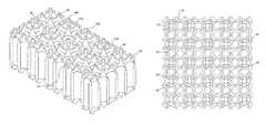
- FIG. 4is an isometric view of a portion of one embodiment of the bottom nozzle top plate and flow through holes of this invention showing recesses in the upper face that interface with the fuel rod end plugs;
- FIG. 5is an isometric view of the embodiment shown in FIG. 4 with the fuel rod end plugs in position;
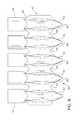
- FIG. 6is a partial side view of the embodiment illustrated in FIGS. 4 and 5 ;
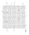
- FIG. 7is a bottom plan view of the embodiment illustrated in FIGS. 4 and 5 ;
- FIG. 8is a top plan view of the embodiment illustrated in FIGS. 4 and 5 (with portions of the end plugs removed);
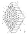
- FIG. 9is a sectioned isometric view of another embodiment of the bottom nozzle top plate and flow through holes of this invention.
- FIG. 10is the sectioned isometric view shown in FIG. 9 with the lower portion of a number of fuel element end plugs shown interfacing with the appendages of this invention;
- FIG. 11is a top view of the horizontal lower nozzle plate of FIGS. 9 and 10 , showing the positioning of the flow through holes;
- FIG. 12is a bottom view of the hole pattern shown in FIG. 11 ;
- FIG. 13is a sectioned side view of the flow holes (shown with the lower end of the fuel rod end plugs).
- the present inventionrelates to a bottom nozzle 58 for a fuel assembly which, in addition to supporting the fuel assembly 22 on the lower core plate 36 , also contains features which function to reduce the pressure drop across the nozzle.
- the bottom nozzleincludes a support means, for example, the skirt 56 shown in FIG. 3 .
- the support means, skirt 56 in this embodimentincludes a plurality of corner legs 60 for supporting the fuel assembly 22 on the lower core plate 36 .
- a generally rectangular, planar plate 86is suitably attached to the upper surface of the support skirt 56 . In the nozzle plate 86 of this embodiment, a large number of relatively small holes are provided to accommodate the passage of coolant from below the plate 86 to and through the lower most grid 88 .
- holesmay be small enough to trap debris to shield the fuel element cladding from damage as described in U.S. Pat. No. 7,822,165, though it should be appreciated that this invention can provide a benefit to most any type of flow through hole in a fuel assembly seeking to minimize pressure drop.
- This inventionrecognizes that a significant portion of the pressure drop associated with the bottom nozzle flow plate 86 is due to abrupt changes in flow area.
- This advanced bottom nozzle conceptincorporates “egg-crate” type features on either or both the upstream and downstream sides of the bottom nozzle flow plate 86 to gradually change the lateral flow area in the flow through path through the flow plate 86 .
- FIGS. 4 through 8show a portion of one embodiment of a flow plate 86 incorporating the features claimed hereafter.
- FIG. 4shows an isometric view of a portion of the flow plate 86 with parts of the flow through holes 90 broken away to observe the interior of the flow through holes.
- FIG. 5is the isometric view illustrated in FIG. 4 with the fuel rod end plugs 74 shown in position above the flow plate 86 .
- FIG. 6is a side view of a portion of the flow plate shown in FIG. 5 .
- FIG. 7is a bottom plan view of the flow plate shown in FIG. 5 ; and
- FIG. 8is a top plan view of the portion of the flow plate shown in FIG. 4 .
- streamlined “egg-crate” protrusions 92gradually reduce the lateral flow area to minimize form losses associated with the rapid contraction that the coolant flow must undergo as it enters the perforated flow plate at the entrance to the flow holes 90 .
- These “egg-crate” protrusions 92also eliminate high pressure pockets of recirculating flow below each fuel rod location.
- the protrusions 92are funnel-like extensions of the openings of the flow through holes 90 with a lip 98 that surrounds an opening on the lower most extent of the protrusions 92 having depressions 94 that in one embodiment are approximately equally spaced around its circumference; though it should be appreciated that the depressions need not be equally spaced to obtain some reduction in pressure drop.
- the depressions in the lip 94form a scalloped contour.
- the protrusions 92 extending on either side of the flow plate 86are shown to be approximately the same height, the height may vary over the surface of the plate and still obtain a reduction in pressure drop.
- streamlined “egg-crate” protrusions 96gradually increase the lateral flow area to minimize form losses associated with the rapid expansion and contraction that the coolant experiences in the transition from the flow plate 86 to the fuel rod bundle. Due to the close proximity of the fuel rod bottom end plugs 74 , the downstream “egg-crate” protrusions are recessed in the upper face of the plate 86 to interface with the fuel rods 66 . There are no changes to the axial elevations of the fuel rods.
- FIGS. 9-13an additional reduction in pressure drop can be achieved employing the embodiment illustrated in FIGS. 9-13 .
- This embodimentretains the streamlined flow passages unique to the foregoing embodiment, which has the flow through holes substantially aligned with the unoccupied spaces between the lowermost grid and the fuel rod, but adds an additional flow path substantially in-line with the fuel rods.
- the additional flow holes 100are of a similar design to the other flow holes 90 , but are positioned directly under the fuel rods, are preferably smaller in diameter and have a set of standoffs 102 supporting the fuel rods and allowing the coolant flow to exit the bottom nozzle.
- the standoffmay be the peaks of the scalloped lips of the appendages and ensure that the fuel rods don't block the flow holes during operation.
- the additional flow holes 100are directly under the fuel rods they provide a “no-line-of-sight” path for the flow which helps minimize debris from passing thru the bottom nozzle yet help reduce the overall loss coefficient of the bottom nozzle by providing an additional flow path. Testing of this added feature showed a significant improvement over the embodiment employing the appendages without the additional flow holes in-line with the fuel rods.
Landscapes
- Physics & Mathematics (AREA)
- Engineering & Computer Science (AREA)
- Plasma & Fusion (AREA)
- General Engineering & Computer Science (AREA)
- High Energy & Nuclear Physics (AREA)
- Monitoring And Testing Of Nuclear Reactors (AREA)
- Heat-Exchange Devices With Radiators And Conduit Assemblies (AREA)
- Feeding, Discharge, Calcimining, Fusing, And Gas-Generation Devices (AREA)
- Fuel-Injection Apparatus (AREA)
Abstract
Description
Claims (22)
Priority Applications (7)
| Application Number | Priority Date | Filing Date | Title |
|---|---|---|---|
| US14/243,954US9847144B1 (en) | 2014-04-03 | 2014-04-03 | Low pressure drop nuclear fuel assembly bottom nozzle |
| EP15793124.7AEP3127122B1 (en) | 2014-04-03 | 2015-02-12 | Low pressure drop nuclear fuel assembly |
| JP2016554652AJP6541680B2 (en) | 2014-04-03 | 2015-02-12 | Lower fuel assembly lower nozzle with less pressure drop |
| KR1020167030389AKR102239043B1 (en) | 2014-04-03 | 2015-02-12 | Low pressure drop nuclear fuel assembly bottom nozzle |
| CN201580015375.8ACN106104700B (en) | 2014-04-03 | 2015-02-12 | Low pressure drop nuclear fuel assembly bottom nozzle |
| PCT/US2015/015521WO2015175041A2 (en) | 2014-04-03 | 2015-02-12 | Low pressure drop nuclear fuel assembly bottom nozzle |
| ES15793124TES2721004T3 (en) | 2014-04-03 | 2015-02-12 | Nuclear fuel assembly with low pressure drop |
Applications Claiming Priority (1)
| Application Number | Priority Date | Filing Date | Title |
|---|---|---|---|
| US14/243,954US9847144B1 (en) | 2014-04-03 | 2014-04-03 | Low pressure drop nuclear fuel assembly bottom nozzle |
Publications (2)
| Publication Number | Publication Date |
|---|---|
| US20170352438A1 US20170352438A1 (en) | 2017-12-07 |
| US9847144B1true US9847144B1 (en) | 2017-12-19 |
Family
ID=54480893
Family Applications (1)
| Application Number | Title | Priority Date | Filing Date |
|---|---|---|---|
| US14/243,954Active2037-07-24US9847144B1 (en) | 2014-04-03 | 2014-04-03 | Low pressure drop nuclear fuel assembly bottom nozzle |
Country Status (7)
| Country | Link |
|---|---|
| US (1) | US9847144B1 (en) |
| EP (1) | EP3127122B1 (en) |
| JP (1) | JP6541680B2 (en) |
| KR (1) | KR102239043B1 (en) |
| CN (1) | CN106104700B (en) |
| ES (1) | ES2721004T3 (en) |
| WO (1) | WO2015175041A2 (en) |
Cited By (1)
| Publication number | Priority date | Publication date | Assignee | Title |
|---|---|---|---|---|
| WO2020236702A2 (en) | 2019-05-21 | 2020-11-26 | Westinghouse Electric Company Llc | Bottom nozzle with internal debris filter |
Families Citing this family (7)
| Publication number | Priority date | Publication date | Assignee | Title |
|---|---|---|---|---|
| KR102523408B1 (en) | 2017-03-17 | 2023-04-18 | 웨스팅하우스 일렉트릭 컴퍼니 엘엘씨 | Fuel Assembly Debris Filtration Lower Nozzle |
| US11014265B2 (en) | 2017-03-20 | 2021-05-25 | Battelle Energy Alliance, Llc | Methods and apparatus for additively manufacturing structures using in situ formed additive manufacturing materials |
| US10720246B2 (en) | 2017-04-20 | 2020-07-21 | Westinghouse Electric Company Llc | Fuel assembly arrangement for retaining fuel rod end plug to bottom nozzle |
| CN107195341A (en)* | 2017-05-17 | 2017-09-22 | 华北电力大学 | The on-line monitoring device that nuclear power plant containment shell fragment influences on fuel assembly pressure drop |
| KR102162013B1 (en)* | 2019-01-16 | 2020-10-07 | 한전원자력연료 주식회사 | A bottom nozzle of Nuclear Fuel Assembly formed spiral type flow hole |
| CN110993128A (en)* | 2019-12-02 | 2020-04-10 | 吉林农业大学 | Grillwork for pressurized water reactor fuel assembly |
| CN115798746A (en)* | 2022-12-12 | 2023-03-14 | 中广核研究院有限公司 | Nuclear fuel assembly lower pipe seat for limiting vibration of fuel rod |
Citations (14)
| Publication number | Priority date | Publication date | Assignee | Title |
|---|---|---|---|---|
| US4684495A (en)* | 1984-11-16 | 1987-08-04 | Westinghouse Electric Corp. | Fuel assembly bottom nozzle with integral debris trap |
| US5009839A (en)* | 1990-09-04 | 1991-04-23 | B&W Fuel Company | Nuclear fuel assembly bottom nozzle plate |
| US5225152A (en)* | 1990-11-20 | 1993-07-06 | Framatome | Filtering bottom nozzle for a fuel assembly of a lightwater-cooled reactor |
| EP0563694A2 (en) | 1992-03-30 | 1993-10-06 | Siemens Power Corporation | Low pressure drop spacer for nuclear fuel assemblies |
| US5255297A (en)* | 1990-09-14 | 1993-10-19 | Combustion Engineering, Inc. | Lower end fitting with multistage flow diffusers |
| US5283812A (en)* | 1991-10-04 | 1994-02-01 | Framatome | Bottom nozzle of a fuel assembly for a water-cooled nuclear reactor |
| US5867551A (en)* | 1996-09-13 | 1999-02-02 | Nuclear Fuel Industries, Ltd. | Nuclear fuel assembly for pressurized water reactor |
| US6421407B1 (en) | 1999-06-11 | 2002-07-16 | Korea Atomic Energy Research Institute | Nuclear fuel spacer grid with dipper vanes |
| US6608880B2 (en)* | 2001-07-17 | 2003-08-19 | Westinghouse Electric Co. Llc | Reduced pressure drop debris filter bottom nozzle for a fuel assembly of a nuclear reactor |
| US20060045231A1 (en) | 2004-09-02 | 2006-03-02 | Lee Yu C | Nuclear fuel assembly protective grid |
| US7085340B2 (en) | 2003-09-05 | 2006-08-01 | Westinghouse Electric Co, Llc | Nuclear reactor fuel assemblies |
| US7822165B2 (en)* | 2004-01-05 | 2010-10-26 | Westinghouse Electric Co Llc | Nuclear fuel assembly debris filter bottom nozzle |
| JP2011503534A (en) | 2007-11-05 | 2011-01-27 | アレヴァ エヌペ | Nuclear fuel rod spacer grid and framework and fuel assembly including such a grid |
| US8369475B2 (en) | 2009-07-01 | 2013-02-05 | Westinghouse Electric Company Llc | Nuclear fuel assembly support grid |
Family Cites Families (9)
| Publication number | Priority date | Publication date | Assignee | Title |
|---|---|---|---|---|
| JPS56153284A (en)* | 1980-04-30 | 1981-11-27 | Tokyo Shibaura Electric Co | Fuel assembly |
| JPS63120289A (en)* | 1986-11-10 | 1988-05-24 | 株式会社東芝 | Fuel aggregate |
| JPS63275990A (en)* | 1987-05-08 | 1988-11-14 | Toshiba Corp | Fuel assembly |
| US5345483A (en)* | 1993-12-02 | 1994-09-06 | General Electric Company | Lower tie plate strainers having double plate with offset holes for boiling water reactors |
| JP2001133574A (en)* | 1999-11-01 | 2001-05-18 | Nuclear Fuel Ind Ltd | Lower tie plate of fuel assembly |
| SE521610C2 (en)* | 2001-01-22 | 2003-11-18 | Westinghouse Atom Ab | Filters and fuel cartridge for a light-water nuclear plant |
| KR100444699B1 (en)* | 2001-12-26 | 2004-08-21 | 한국수력원자력 주식회사 | lips-type multi-purposed nuclear fuel assembly spacer grid |
| FR2910170B1 (en)* | 2006-12-13 | 2009-04-03 | Areva Np Sas | LOWER CAP WITH AN ANTI-DEBRIS DEVICE FOR CHICAN NUCLEAR FUEL ASSEMBLY AND CORRESPONDING ASSEMBLY |
| KR101535357B1 (en)* | 2013-12-31 | 2015-07-08 | 한국원자력연구원 | A bottom end plate in a dual-cooled annular nuclear fuel assembly |
- 2014
- 2014-04-03USUS14/243,954patent/US9847144B1/enactiveActive
- 2015
- 2015-02-12CNCN201580015375.8Apatent/CN106104700B/enactiveActive
- 2015-02-12KRKR1020167030389Apatent/KR102239043B1/enactiveActive
- 2015-02-12ESES15793124Tpatent/ES2721004T3/enactiveActive
- 2015-02-12WOPCT/US2015/015521patent/WO2015175041A2/enactiveApplication Filing
- 2015-02-12EPEP15793124.7Apatent/EP3127122B1/enactiveActive
- 2015-02-12JPJP2016554652Apatent/JP6541680B2/ennot_activeExpired - Fee Related
Patent Citations (15)
| Publication number | Priority date | Publication date | Assignee | Title |
|---|---|---|---|---|
| US4684495A (en)* | 1984-11-16 | 1987-08-04 | Westinghouse Electric Corp. | Fuel assembly bottom nozzle with integral debris trap |
| US5009839A (en)* | 1990-09-04 | 1991-04-23 | B&W Fuel Company | Nuclear fuel assembly bottom nozzle plate |
| US5255297A (en)* | 1990-09-14 | 1993-10-19 | Combustion Engineering, Inc. | Lower end fitting with multistage flow diffusers |
| US5225152A (en)* | 1990-11-20 | 1993-07-06 | Framatome | Filtering bottom nozzle for a fuel assembly of a lightwater-cooled reactor |
| US5283812A (en)* | 1991-10-04 | 1994-02-01 | Framatome | Bottom nozzle of a fuel assembly for a water-cooled nuclear reactor |
| EP0563694A2 (en) | 1992-03-30 | 1993-10-06 | Siemens Power Corporation | Low pressure drop spacer for nuclear fuel assemblies |
| US5867551A (en)* | 1996-09-13 | 1999-02-02 | Nuclear Fuel Industries, Ltd. | Nuclear fuel assembly for pressurized water reactor |
| US6421407B1 (en) | 1999-06-11 | 2002-07-16 | Korea Atomic Energy Research Institute | Nuclear fuel spacer grid with dipper vanes |
| US6608880B2 (en)* | 2001-07-17 | 2003-08-19 | Westinghouse Electric Co. Llc | Reduced pressure drop debris filter bottom nozzle for a fuel assembly of a nuclear reactor |
| KR20040040432A (en) | 2001-07-17 | 2004-05-12 | 웨스팅하우스 일레트릭 캄파니 엘엘씨 | Reduced Pressure Drop Debris Filter Bottom Nozzle For A Fuel Assembly Of A Nuclear Reactor |
| US7085340B2 (en) | 2003-09-05 | 2006-08-01 | Westinghouse Electric Co, Llc | Nuclear reactor fuel assemblies |
| US7822165B2 (en)* | 2004-01-05 | 2010-10-26 | Westinghouse Electric Co Llc | Nuclear fuel assembly debris filter bottom nozzle |
| US20060045231A1 (en) | 2004-09-02 | 2006-03-02 | Lee Yu C | Nuclear fuel assembly protective grid |
| JP2011503534A (en) | 2007-11-05 | 2011-01-27 | アレヴァ エヌペ | Nuclear fuel rod spacer grid and framework and fuel assembly including such a grid |
| US8369475B2 (en) | 2009-07-01 | 2013-02-05 | Westinghouse Electric Company Llc | Nuclear fuel assembly support grid |
Non-Patent Citations (1)
| Title |
|---|
| Westinghouse Electric Company LLC, PCT/US2015/015521, PCT International Search Report, Nov. 27, 2015, 10 pages. |
Cited By (2)
| Publication number | Priority date | Publication date | Assignee | Title |
|---|---|---|---|---|
| WO2020236702A2 (en) | 2019-05-21 | 2020-11-26 | Westinghouse Electric Company Llc | Bottom nozzle with internal debris filter |
| TWI731692B (en)* | 2019-05-21 | 2021-06-21 | 美商西屋電器公司 | Bottom nozzle with internal debris filter and method of manufacturing debris filter bottom nozzle |
Also Published As
| Publication number | Publication date |
|---|---|
| KR20160138565A (en) | 2016-12-05 |
| EP3127122A4 (en) | 2018-02-14 |
| EP3127122B1 (en) | 2019-01-30 |
| US20170352438A1 (en) | 2017-12-07 |
| CN106104700B (en) | 2017-07-18 |
| EP3127122A2 (en) | 2017-02-08 |
| CN106104700A (en) | 2016-11-09 |
| JP2017522538A (en) | 2017-08-10 |
| WO2015175041A3 (en) | 2016-01-14 |
| JP6541680B2 (en) | 2019-07-10 |
| WO2015175041A2 (en) | 2015-11-19 |
| KR102239043B1 (en) | 2021-04-09 |
| ES2721004T3 (en) | 2019-07-26 |
Similar Documents
| Publication | Publication Date | Title |
|---|---|---|
| US9847144B1 (en) | Low pressure drop nuclear fuel assembly bottom nozzle | |
| US7085340B2 (en) | Nuclear reactor fuel assemblies | |
| US9305668B2 (en) | Pressurized water reactor flow skirt apparatus | |
| US8908822B2 (en) | Nuclear reactor | |
| US9020091B2 (en) | Nuclear fuel assembly with a lock-support spacer grid | |
| CN110603602B (en) | Annular nuclear fuel pellets with discrete burnable absorber pins | |
| KR102109504B1 (en) | Pressurizer surge-line separator for integral pressurized water reactors | |
| CN104813410B (en) | Nuclear reactor with weight radial direction neutron reflector | |
| US20140270047A1 (en) | Rib-type roughness design for improved heat transfer in pwr rod bundles | |
| US9536628B2 (en) | Nuclear fuel assembly support grid | |
| US20110002435A1 (en) | Nuclear fuel assembly support grid | |
| KR20170015986A (en) | Crush resistant nuclear fuel assembly support grid | |
| US9847143B2 (en) | Nuclear fuel element | |
| KR102397744B1 (en) | Control rod guide tube with an extended intermediate guide assembly | |
| KR20130133232A (en) | Nuclear fuel rod plenum spring assembly | |
| EP2511909A2 (en) | Nuclear fuel pellet | |
| US20130070890A1 (en) | Grooved nuclear fuel assembly component insert | |
| KR102468162B1 (en) | Pressurized water reactor fuel assembly | |
| JP5361964B2 (en) | Initial loading core of nuclear reactor | |
| US20130272482A1 (en) | Pressurized water reactor fuel assembly grid | |
| JP2014163806A (en) | Fuel assembly |
Legal Events
| Date | Code | Title | Description |
|---|---|---|---|
| AS | Assignment | Owner name:WESTINGHOUSE ELECTRIC COMPANY LLC, PENNSYLVANIA Free format text:ASSIGNMENT OF ASSIGNORS INTEREST;ASSIGNORS:BROACH, KIRKLAND D.;LEWIS, MICHAEL L.;PETERSON, MARK W.;AND OTHERS;REEL/FRAME:032590/0546 Effective date:20140402 | |
| STCF | Information on status: patent grant | Free format text:PATENTED CASE | |
| AS | Assignment | Owner name:GOLDMAN SACHS BANK USA, AS COLLATERAL AGENT, NEW YORK Free format text:SECURITY INTEREST;ASSIGNORS:WESTINGHOUSE ELECTRIC COMPANY LLC;FAUSKE AND ASSOCIATES LLC;REEL/FRAME:046708/0332 Effective date:20180801 Owner name:CREDIT SUISSE AG, CAYMAN ISLANDS BRANCH, AS COLLATERAL AGENT, NEW YORK Free format text:SECURITY INTEREST;ASSIGNORS:WESTINGHOUSE ELECTRIC COMPANY LLC;FAUSKE AND ASSOCIATES LLC;REEL/FRAME:046708/0222 Effective date:20180801 Owner name:BANK OF MONTREAL, AS ADMINISTRATIVE AGENT, ILLINOIS Free format text:SECURITY INTEREST;ASSIGNORS:WESTINGHOUSE ELECTRIC COMPANY LLC;FAUSKE AND ASSOCIATES LLC;REEL/FRAME:046708/0639 Effective date:20180801 Owner name:CREDIT SUISSE AG, CAYMAN ISLANDS BRANCH, AS COLLAT Free format text:SECURITY INTEREST;ASSIGNORS:WESTINGHOUSE ELECTRIC COMPANY LLC;FAUSKE AND ASSOCIATES LLC;REEL/FRAME:046708/0222 Effective date:20180801 Owner name:GOLDMAN SACHS BANK USA, AS COLLATERAL AGENT, NEW Y Free format text:SECURITY INTEREST;ASSIGNORS:WESTINGHOUSE ELECTRIC COMPANY LLC;FAUSKE AND ASSOCIATES LLC;REEL/FRAME:046708/0332 Effective date:20180801 Owner name:BANK OF MONTREAL, AS ADMINISTRATIVE AGENT, ILLINOI Free format text:SECURITY INTEREST;ASSIGNORS:WESTINGHOUSE ELECTRIC COMPANY LLC;FAUSKE AND ASSOCIATES LLC;REEL/FRAME:046708/0639 Effective date:20180801 | |
| AS | Assignment | Owner name:FAUSKE AND ASSOCIATES LLC, ILLINOIS Free format text:RELEASE OF SECURITY INTEREST IN PATENTS;ASSIGNOR:GOLDMAN SACHS BANK USA, AS COLLATERAL AGENT;REEL/FRAME:049937/0032 Effective date:20190801 Owner name:WESTINGHOUSE ELECTRIC COMPANY LLC, PENNSYLVANIA Free format text:RELEASE OF SECURITY INTEREST IN PATENTS;ASSIGNOR:GOLDMAN SACHS BANK USA, AS COLLATERAL AGENT;REEL/FRAME:049937/0032 Effective date:20190801 | |
| MAFP | Maintenance fee payment | Free format text:PAYMENT OF MAINTENANCE FEE, 4TH YEAR, LARGE ENTITY (ORIGINAL EVENT CODE: M1551); ENTITY STATUS OF PATENT OWNER: LARGE ENTITY Year of fee payment:4 | |
| AS | Assignment | Owner name:BANK OF MONTREAL, AS COLLATERAL AGENT, ILLINOIS Free format text:PATENT SECURITY AGREEMENT;ASSIGNORS:WESTINGHOUSE ELECTRIC COMPANY LLC;BHI ENERGY I SPECIALTY SERVICES LLC;REEL/FRAME:060791/0372 Effective date:20220527 | |
| AS | Assignment | Owner name:DEUTSCHE BANK AG NEW YORK BRANCH, AS COLLATERAL AGENT, NEW YORK Free format text:SECURITY INTEREST;ASSIGNORS:WESTINGHOUSE ELECTRIC COMPANY LLC;BHI ENERGY I SPECIALTY SERVICES LLC;STONE & WEBSTER, L.L.C. (FORMERLY STONE & WEBSTER, INC.);REEL/FRAME:066373/0604 Effective date:20240125 | |
| AS | Assignment | Owner name:BHI ENERGY I SPECIALTY SERVICES LLC, GEORGIA Free format text:RELEASE OF SECURITY INTEREST IN PATENTS;ASSIGNOR:BANK OF MONTREAL, AS COLLATERAL AGENT;REEL/FRAME:066380/0599 Effective date:20240125 Owner name:WESTINGHOUSE ELECTRIC COMPANY LLC, PENNSYLVANIA Free format text:RELEASE OF SECURITY INTEREST IN PATENTS;ASSIGNOR:BANK OF MONTREAL, AS COLLATERAL AGENT;REEL/FRAME:066380/0599 Effective date:20240125 Owner name:FAUSKE AND ASSOCIATES LLC, ILLINOIS Free format text:RELEASE OF SECURITY INTEREST IN PATENTS;ASSIGNOR:CREDIT SUISSE AG, CAYMAN ISLANDS, AS COLLATERAL AGENT;REEL/FRAME:066380/0392 Effective date:20240125 Owner name:WESTINGHOUSE ELECTRIC COMPANY LLC, PENNSYLVANIA Free format text:RELEASE OF SECURITY INTEREST IN PATENTS;ASSIGNOR:CREDIT SUISSE AG, CAYMAN ISLANDS, AS COLLATERAL AGENT;REEL/FRAME:066380/0392 Effective date:20240125 | |
| MAFP | Maintenance fee payment | Free format text:PAYMENT OF MAINTENANCE FEE, 8TH YEAR, LARGE ENTITY (ORIGINAL EVENT CODE: M1552); ENTITY STATUS OF PATENT OWNER: LARGE ENTITY Year of fee payment:8 |