US9845210B2 - Conveyor with integrated dust collector system - Google Patents
Conveyor with integrated dust collector systemDownload PDFInfo
- Publication number
- US9845210B2 US9845210B2US15/398,835US201715398835AUS9845210B2US 9845210 B2US9845210 B2US 9845210B2US 201715398835 AUS201715398835 AUS 201715398835AUS 9845210 B2US9845210 B2US 9845210B2
- Authority
- US
- United States
- Prior art keywords
- proppant
- dust particles
- hood
- dust
- assembly
- Prior art date
- Legal status (The legal status is an assumption and is not a legal conclusion. Google has not performed a legal analysis and makes no representation as to the accuracy of the status listed.)
- Active
Links
Images


Classifications
- B—PERFORMING OPERATIONS; TRANSPORTING
- B65—CONVEYING; PACKING; STORING; HANDLING THIN OR FILAMENTARY MATERIAL
- B65G—TRANSPORT OR STORAGE DEVICES, e.g. CONVEYORS FOR LOADING OR TIPPING, SHOP CONVEYOR SYSTEMS OR PNEUMATIC TUBE CONVEYORS
- B65G69/00—Auxiliary measures taken, or devices used, in connection with loading or unloading
- B65G69/18—Preventing escape of dust
- B65G69/181—Preventing escape of dust by means of sealed systems
- B01F13/0037—
- B—PERFORMING OPERATIONS; TRANSPORTING
- B01—PHYSICAL OR CHEMICAL PROCESSES OR APPARATUS IN GENERAL
- B01F—MIXING, e.g. DISSOLVING, EMULSIFYING OR DISPERSING
- B01F33/00—Other mixers; Mixing plants; Combinations of mixers
- B01F33/50—Movable or transportable mixing devices or plants
- B01F33/502—Vehicle-mounted mixing devices
- B01F33/5021—Vehicle-mounted mixing devices the vehicle being self-propelled, e.g. truck mounted, provided with a motor, driven by tracks
- B—PERFORMING OPERATIONS; TRANSPORTING
- B65—CONVEYING; PACKING; STORING; HANDLING THIN OR FILAMENTARY MATERIAL
- B65C—LABELLING OR TAGGING MACHINES, APPARATUS, OR PROCESSES
- B65C11/00—Manually-controlled or manually-operable label dispensers, e.g. modified for the application of labels to articles
- B—PERFORMING OPERATIONS; TRANSPORTING
- B65—CONVEYING; PACKING; STORING; HANDLING THIN OR FILAMENTARY MATERIAL
- B65G—TRANSPORT OR STORAGE DEVICES, e.g. CONVEYORS FOR LOADING OR TIPPING, SHOP CONVEYOR SYSTEMS OR PNEUMATIC TUBE CONVEYORS
- B65G11/00—Chutes
- B—PERFORMING OPERATIONS; TRANSPORTING
- B65—CONVEYING; PACKING; STORING; HANDLING THIN OR FILAMENTARY MATERIAL
- B65G—TRANSPORT OR STORAGE DEVICES, e.g. CONVEYORS FOR LOADING OR TIPPING, SHOP CONVEYOR SYSTEMS OR PNEUMATIC TUBE CONVEYORS
- B65G15/00—Conveyors having endless load-conveying surfaces, i.e. belts and like continuous members, to which tractive effort is transmitted by means other than endless driving elements of similar configuration
- B—PERFORMING OPERATIONS; TRANSPORTING
- B65—CONVEYING; PACKING; STORING; HANDLING THIN OR FILAMENTARY MATERIAL
- B65G—TRANSPORT OR STORAGE DEVICES, e.g. CONVEYORS FOR LOADING OR TIPPING, SHOP CONVEYOR SYSTEMS OR PNEUMATIC TUBE CONVEYORS
- B65G53/00—Conveying materials in bulk through troughs, pipes or tubes by floating the materials or by flow of gas, liquid or foam
- B65G53/04—Conveying materials in bulk pneumatically through pipes or tubes; Air slides
- B65G53/24—Gas suction systems
- B65G53/26—Gas suction systems operating with fluidisation of the materials
- B—PERFORMING OPERATIONS; TRANSPORTING
- B65—CONVEYING; PACKING; STORING; HANDLING THIN OR FILAMENTARY MATERIAL
- B65G—TRANSPORT OR STORAGE DEVICES, e.g. CONVEYORS FOR LOADING OR TIPPING, SHOP CONVEYOR SYSTEMS OR PNEUMATIC TUBE CONVEYORS
- B65G65/00—Loading or unloading
- B65G65/30—Methods or devices for filling or emptying bunkers, hoppers, tanks, or like containers, of interest apart from their use in particular chemical or physical processes or their application in particular machines, e.g. not covered by a single other subclass
- B65G65/34—Emptying devices
- B65G65/40—Devices for emptying otherwise than from the top
- B65G65/42—Devices for emptying otherwise than from the top using belt or chain conveyors
- B—PERFORMING OPERATIONS; TRANSPORTING
- B65—CONVEYING; PACKING; STORING; HANDLING THIN OR FILAMENTARY MATERIAL
- B65G—TRANSPORT OR STORAGE DEVICES, e.g. CONVEYORS FOR LOADING OR TIPPING, SHOP CONVEYOR SYSTEMS OR PNEUMATIC TUBE CONVEYORS
- B65G69/00—Auxiliary measures taken, or devices used, in connection with loading or unloading
- B65G69/18—Preventing escape of dust
- B65G69/181—Preventing escape of dust by means of sealed systems
- B65G69/182—Preventing escape of dust by means of sealed systems with aspiration means
- E—FIXED CONSTRUCTIONS
- E21—EARTH OR ROCK DRILLING; MINING
- E21B—EARTH OR ROCK DRILLING; OBTAINING OIL, GAS, WATER, SOLUBLE OR MELTABLE MATERIALS OR A SLURRY OF MINERALS FROM WELLS
- E21B41/00—Equipment or details not covered by groups E21B15/00 - E21B40/00
- E—FIXED CONSTRUCTIONS
- E21—EARTH OR ROCK DRILLING; MINING
- E21B—EARTH OR ROCK DRILLING; OBTAINING OIL, GAS, WATER, SOLUBLE OR MELTABLE MATERIALS OR A SLURRY OF MINERALS FROM WELLS
- E21B43/00—Methods or apparatus for obtaining oil, gas, water, soluble or meltable materials or a slurry of minerals from wells
- E21B43/25—Methods for stimulating production
- E21B43/26—Methods for stimulating production by forming crevices or fractures
- E21B43/2607—Surface equipment specially adapted for fracturing operations
- E—FIXED CONSTRUCTIONS
- E21—EARTH OR ROCK DRILLING; MINING
- E21B—EARTH OR ROCK DRILLING; OBTAINING OIL, GAS, WATER, SOLUBLE OR MELTABLE MATERIALS OR A SLURRY OF MINERALS FROM WELLS
- E21B43/00—Methods or apparatus for obtaining oil, gas, water, soluble or meltable materials or a slurry of minerals from wells
- E21B43/25—Methods for stimulating production
- E21B43/26—Methods for stimulating production by forming crevices or fractures
- E21B43/267—Methods for stimulating production by forming crevices or fractures reinforcing fractures by propping
Definitions
- the present inventionrelates to collecting dust particles. More particularly, the present invention relates to systems and methods to collect dust particles formed during the movement of proppant.
- FrackingHydraulic fracturing or “fracking” has been used for decades to stimulate production from conventional oil and gas wells. In recent years, the use of fracking has increased due to the development of new drilling technology such as horizontal drilling and multi-stage fracking. Such techniques reach previously-unavailable deposits of natural gas and oil. Fracking generally includes pumping fluid into a wellbore at high pressure. Inside the wellbore, the fluid is forced into the formation being produced. When the fluid enters the formation, it fractures, or creates fissures, in the formation. Water, as well as other fluids, and some solid proppants, are then pumped into the fissures to stimulate the release of oil and gas from the formation.
- proppantis silica sand, made up of ancient weathered quartz, the most common mineral in the Earth's continental crust. Unlike common sand, which often feels gritty when rubbed between your fingers, sand used as a proppant tends to roll to the touch as a result of its round, spherical shape and tightly-graded particle distribution. Sand quality is a function of both deposit and processing. Grain size is critical, as any given proppant should reliably fall within certain mesh ranges, subject to downhole conditions and completion design. Generally, coarser proppant allows a higher capacity due to the larger pore spaces between grains. This type of proppant, however, may break down or crush more readily under stress due to the relatively fewer grain-to-grain contact points to bear the stress often incurred in deep oil- and gas-bearing formations.
- a system for capturing proppant dust particles when positioned at a fracking operation siteincludes a proppant delivery assembly to receive one or more containers having proppant stored therein. The system dispenses the proppant from the one or more containers and delivers the proppant to other fracking operation equipment. Moreover, the system includes a dust collection assembly positioned proximate and associated with the proppant delivery assembly to capture dust particles released by movement and settling of the proppant when being dispensed and delivered by the proppant delivery assembly. The dust collection assembly is positioned to direct an air flow in a flow path overlying the dust particles to capture the dust particles and move the dust particles away from the proppant thereby reducing risk of dust exposure to fracking operation site personnel.
- a system for capturing proppant dust particles when positioned at a fracking operation siteincludes a proppant delivery assembly supporting one or more contains having proppant stored therein.
- the one or more containersare arranged to dispense proppant to a chute that directs the dispensed proppant to a desired location.
- the systemalso includes a dust collection assembly positioned proximate and at least partially coupled to the proppant delivery system to capture dust particles released by movement and settling of the proppant when being dispensed and directed to the desired location.
- the dust collection assemblyis positioned to draw a volume of air containing dust particles proximate the desired location away from the desired location to reduce the risk of dust exposure to personnel near the desired location.
- a method of capturing proppant dust particles when positioned at a fracking operation siteincludes delivering proppant stored in one or more containers to fracking operation equipment via a proppant delivery assembly. The method also includes capturing proppant dust particles formed by the movement and settling of the proppant at the fracking operation equipment via an air flow directed in a flow path overlying the dust particles. The method further includes removing the proppant dust particles from the fracking operation equipment by directing the air flow away from the fracking operation equipment.
- a catch boxis arranged proximate a lower surface of a proppant mover to catch proppant and dust particles as the proppant is transferred from the proppant mover to a desired location.
- the catch boxincludes an inlet positioned below the proppant mover to catch residual proppant and dust particles after the proppant mover has deposited proppant into a chute that directs the proppant to the desired location.
- the catch boxalso includes an interior volume to store the residual proppant and dust.
- the catch boxincludes an outlet having a conduit connection to enable removal of the residual proppant and dust particles via suction at the outlet.
- a hood assembly to direct a vacuum air flow that removes a volume of air containing proppant dust particles after a proppant has been transported to a desired location from a flow pathincludes a first hood section that substantially surrounds and receives an outlet of a chute that directs the proppant to the desired location.
- the first hood sectionincludes at least one dust receptacle extending through a body of the first hood section to enable a volume of air to exit the first hood section.
- the hood assemblyalso includes a second hood section positioned adjacent the first hood section and comprising at least one dust receptacle to receive the volume of air.
- the cradleenables the one or more containers to dispense the proppant stored therein.
- the proppant delivery assemblyalso includes a proppant mover positioned below the top surface of the cradle and aligned with the one or more containers to receive the proppant when the proppant is dispensed from the one or more containers.
- the proppant movercarries the proppant away from the one or more containers.
- the proppant delivery assemblyalso includes a directable chute that receives the proppant from the proppant mover and directs the proppant to a desired location, the chute being coupled to the cradle and movable about an axis to change the location where the proppant is dispensed.
- a dust collection assemblyto collect and remove dust particles in a volume of air, the dust particles formed by the movement and settling of proppant, includes a hood assembly positioned proximate the volume of air having the dust particles.
- the hood assemblydirects at least a portion of the volume of air toward one or more dust receptacles extending through the hood assembly and defines at least a portion of the volume of air.
- the dust receptaclesare positioned to direct at least a portion of the volume of air away from the hood assembly.
- the dust collection assemblyalso includes a vacuum air unit fluidly coupled to the hood assembly at the one or more dust receptacles. The vacuum air unit generates suction pressure to draw at least a portion of the volume of air out of the hood assembly through the one or more dust receptacles.
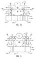
- FIG. 1is a front perspective view of a proppant delivery system having a dust collection assembly according to an embodiment of the present invention
- FIG. 2is a rear perspective view of a proppant delivery system having a dust collection assembly of FIG. 1 according to an embodiment of the present invention
- FIG. 3is a front elevation view of a proppant delivery system having a dust collection assembly of FIG. 1 according to an embodiment of the present invention
- FIG. 4is a rear elevation view of a proppant delivery system having a the dust collection assembly of FIG. 1 according to an embodiment of the present invention
- FIG. 5is a top plan view of a proppant delivery system having a the dust collection assembly of FIG. 1 according to an embodiment of the present invention
- FIG. 6is a top plan view of an embodiment of a dust collection assembly supporting two proppant delivery systems according to another embodiment of the present invention.
- FIG. 7is a partial perspective view of a proppant delivery system positioned to deliver proppant to a blender hopper according to an embodiment of the present invention
- FIG. 8is a perspective view of a hood assembly of a dust collection assembly of FIG. 1 positioned in association with a blender hopper according to an embodiment of the present invention
- FIG. 9is a side elevation view of a hood assembly of FIG. 8 according to an embodiment of the present invention.
- FIG. 10is a front elevation view of a hood assembly of FIG. 8 according to an embodiment of the present invention.
- FIG. 11is a rear elevation view of a hood assembly of FIG. 8 according to an embodiment of the present invention.
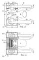
- FIG. 12is a top plan view of a hood assembly of FIG. 8 according to an embodiment of the present invention.
- FIG. 13is a bottom plan view of a hood assembly of FIG. 8 according to an embodiment of the present invention.
- FIG. 14sectional view of a hood assembly of FIG. 8 , taken along line 14 - 14 according to an embodiment of the present invention
- FIG. 15is a sectional view of a hood assembly of FIG. 8 , taken along line 15 - 15 according to an embodiment of the present invention
- FIG. 16is a sectional view of a hood assembly of FIG. 8 , taken along line 16 - 16 according to an embodiment of the present invention
- FIG. 17is a schematic diagram of a conduit system coupling an air mover to the hold assembly of FIG. 8 according to an embodiment of the present invention
- FIG. 18is a top plan view of a hood assembly of FIG. 8 in a first position adjacent a blender hopper according to an embodiment of the present invention
- FIG. 19is a top plan view of a hood assembly of FIG. 8 in a second position adjacent a blender hopper according to an embodiment of the present invention
- FIG. 20is a top plan view of a hood assembly of FIG. 8 in a third position adjacent a blender hopper;
- FIG. 21is a top plan view of a conduit system coupled to the hood assembly of FIG. 8 according to an embodiment of the present invention.
- FIG. 22is a perspective view of a catch box positioned along a conveyor downstream of the chute according to an embodiment of the present invention.
- FIG. 23is a front elevational view of the catch box of FIG. 23 according to an embodiment of the present invention.
- FIG. 24is a side elevational view of the catch box of FIG. 23 according to an embodiment of the present invention.
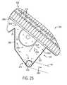
- FIG. 25is a cross-sectional view of the catch box of FIG. 23 , taken along line 25 - 25 according to an embodiment of the present invention
- FIG. 26is a partial side elevation view of proppant being deposited into the catch box of FIG. 23 according to an embodiment of the present invention.
- FIG. 27is a partial side elevation view of an air flow and proppant moving through the system according to an embodiment of the present invention.
- FIG. 28is a perspective view of an air mover of the dust collection assembly arranged proximate the proppant delivery system on a skid according to an embodiment of the present invention
- FIG. 29is a side elevation view of the air mover of FIG. 29 according to an embodiment of the present invention.
- FIG. 30is a rear elevation view of the air mover of FIG. 29 according to an embodiment of the present invention.
- FIG. 31is a back elevation view of the air mover of FIG. 29 having a waste discharge assembly according to a first embodiment of the present invention
- FIG. 32is a back elevation view of the air mover of FIG. 29 having a waste discharge assembly according to a second embodiment of the present invention.
- FIG. 33is a perspective view of a proppant delivery system and a dust collection assembly arranged at a well site according to an embodiment of the present invention
- FIG. 34is a perspective view of a container of a proppant delivery system being loaded onto a cradle of the proppant delivery system according to an embodiment of the present invention
- FIG. 35is a perspective view of the container of FIG. 34 positioned on the cradle and aligned with an actuator of a proppant delivery system having a dust collector assembly according to an embodiment of the present invention
- FIG. 36is a partial sectional view of a container dispensing onto a conveyor of a proppant delivery system having a dust collector assembly according to an embodiment of the present invention
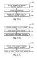
- FIGS. 37A-Dare flow charts illustrating methods for collecting dust particles in fracking operations according to embodiments of the present invention.
- FIG. 38is a flow chart illustrating methods for collecting dust particles and residual proppant in fracking operations according to embodiments of the present invention.
- FIG. 39is a graph illustrating a linear approximation of a range of operation of an air mover according to embodiments of the present invention.
- Embodiments of the present disclosureinclude a system for capturing proppant dust particles.
- a dust collection assemblyis arranged proximate and at least partially coupled to a proppant delivery assembly.
- the proppant delivery assemblyincludes a cradle that receives one or more containers in a side-by-side configuration.
- the containerscontain fracking proppant that is dispensed through an opening at a bottom of each respective container.
- actuators positioned below a top surface of the cradlecan engage a gate 114 covering the opening to enable the proppant to flow out of the one or more containers and onto a proppant mover.
- the proppant moveris an endless conveyor that carries the proppant along a length of the cradle and away from the one or more containers.
- the proppant moverdirects the proppant to a chute arranged at a distal end of the cradle.
- the chuteincludes an inclined surface that directs the proppant into a blender hopper.
- the chuteis directable to enable fracking site operations personnel to direct an outlet of the chute toward a desired location.
- the dust collection assemblyincludes a hood assembly arranged around the outlet of the chute to capture and remove dust particles generated by the movement and settling of the proppant. At least a portion of the hood assembly surrounds the outlet of the chute, thereby being positioned proximate to the location where dust particles are likely to form.
- the hood assemblyincludes one or more dust receptacles that receive the dust captured by the hood assembly.
- the hood assemblyis coupled to an air mover via conduit. That is, tubes, manifolds, and the like couple the air mover to the hood assembly to transmit a suction pressure generated by the air mover to the hood assembly.
- the suction pressuredraws an air flow from a flow path positioned proximate the blender hopper. Accordingly, the dust particles captured in the air flow are drawn away from the blender hopper and moved toward the air mover.
- the suction force generated by the air mover at the hood assemblyis sufficient to capture the dust particles and also designed to reduce the likelihood of lifting the proppant out of the blender hopper. That is, the suction force is particularly selected to minimize the risk of removing proppant from the blender hopper. In this manner, dust particles are removed from the blender hopper to reduce the risk of exposure to fracking operations site personnel.
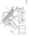
- FIG. 1is a front perspective view of an embodiment of a proppant delivery assembly 10 and a dust collection assembly 12 positioned at a well site 14 .
- the proppant delivery assembly 12includes a cradle 16 that supports proppant containers 18 .
- the containers 18are arranged in a side-by-side configuration along the cradle 16 and positioned proximate to fracking operation equipment, for example, a blender hopper 20 .
- the cradle 16includes a proppant mover 22 that directs the proppant away from the containers 18 after the proppant 18 is dispensed from the containers 18 .
- the proppant mover 22In embodiments where, for example, the proppant mover 22 is a conveyor, the proppant travels along the cradle 16 to a chute 24 that directs the proppant into the blender hopper 20 .
- the proppant mover 22may be a chute, a sloped surface, a screw auger, or the like.
- the proppant mover 22may direct the proppant away from the containers 18 without moving along the cradle 16 .
- the proppant mover 22can be a screw auger that directs the proppant to a side of the cradle 16 .
- the proppantAt the blender hopper 20 , the proppant can be mixed with fracking fluid (e.g., water, chemicals, etc.) for injection into a wellbore 26 .
- fracking fluide.g., water, chemicals, etc.
- the containers 18 in the illustrated embodimentare substantially sealed, self-contained, and modular to enable transportation and storage of the proppant while minimizing the risk of exposure of the proppant and/or dust particles formed from the proppant. Furthermore, substantially sealed containers 18 can isolate the proppant from the environment, thereby reducing the risk of water or contaminants from mixing with the proppant. For example, the containers 18 may be delivered to the well site 14 filled with proppant, stacked into a vertical configuration until the proppant is ready for use, and then arranged on the cradle 16 in the illustrated side-by-side configuration. Once on the cradle 16 , the proppant containers 18 may be opened such that the proppant flows out of a bottom of the containers 18 and onto the proppant mover 22 .
- the proppant mover 22can be an endless conveyor that receives the proppant on a surface and directs the proppant away from the containers 18 .
- the proppant mover 22may be a screw auger, sloped ramp, or the like to facilitate movement of the proppant from one location to another. In this manner, proppant can be moved from the containers 18 to the blender hopper 20 .
- the dust collection assembly 12is positioned proximate the proppant delivery assembly 10 , in the illustrated embodiment. Positioning the dust collection assembly 12 close by the proppant delivery assembly 10 not only reduces the footprint of the overall system at the well site 14 , but also reduces the quantity of conduit connecting the dust collection assembly 12 to the proppant delivery assembly 10 .
- the dust collection assembly 12includes an air mover 28 that draws a vacuum at a desired location where the proppant is being loaded into the blender hopper 20 . That is, the air mover 28 generates a suction pressure proximate the blender hopper 20 to remove dust particles in a volume of air.
- the dust particles that are formed due to the movement and settling of the proppantwill be captured by an air flow generated by the air mover 28 .
- the desired locationis the blender hopper 20 .
- dust particlesmay separate from the proppant and enter the air. These dust particles may infiltrate mechanical equipment, thereby reducing reliability or increasing maintenance intervals. Or, in certain cases, the dust particles may be inhaled by fracking operation site personnel at the well site 14 .
- the dust particlescan be captured and removed from the blender hopper 20 , thereby reducing the risk of exposure to both workers and equipment.
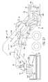
- FIG. 2is a back perspective view of the dust collection assembly 12 arranged proximate the proppant delivery assembly 10 .
- the dust collection assembly 12is arranged on a back side of the proppant delivery assembly 10 to keep at least one side of the cradle 16 free from obstructions.
- the containers 18can be loaded and unloaded from the cradle 16 via a forklift.
- the containers 18may be stacked at the well site 14 in a vertical configuration until such time as they are ready for use.
- the forkliftmay lift the containers 18 from the stacked configuration and carry the containers 18 to the cradle 16 for alignment and deposition on a top surface of the cradle 16 to facilitate dispensing of the proppant from the containers 18 .
- the forkliftmay continuously add and remove containers 18 from the cradle 16 , thereby enabling ongoing fracking operations as containers 18 are emptied of the proppant.
- the containers 18are emptied onto the proppant mover 22 to facilitate movement of the proppant to the blender hopper 20 .
- the dust collection assembly 12may be worked on (e.g., routine maintenance, installation, optimization, etc.) while the containers 18 are positioned on the cradle 16 because the dust collection assembly 12 is separated from the movement area of the forklifts by the cradle 16 . In this manner, the dust collection assembly 12 may be installed and placed into commission at the same time that the containers 18 are installed on the cradle 16 , thereby improving efficiencies at the well site 14 and potentially reducing the duration of set up at the well site 14 .
- the air mover 28is positioned near a rear end 30 or proximal end of the cradle 16 , away from the chute 24 arranged at a distal end 32 of the cradle 16 . Accordingly, workers at the well site 14 can maintain a distance from the vacuum suction, generated by the air mover 28 , at the blender hopper 20 and/or chute 24 when working on or near the air mover 28 . As such, the risk of exposure to the dust particles is further decreased.
- the dust collection assembly 12is designed to substantially integrate with the proppant delivery assembly to minimize the equipment's footprint at the well site 14 and to reduce the amount of additional equipment utilized by the dust collection assembly 12 .
- FIG. 3is a front elevation view of an embodiment of the dust collection assembly 12 arranged in front of (e.g., relative to the plane of the page) and proximate the proppant delivery assembly 10 .
- the dust collection assembly 12is arranged proximate the proppant delivery assembly 10 to remove dust particles that are produced at a desired location of proppant dispersion.
- the overall footprintmay be reduced at the well site 14 .
- the containers 18(shown in phantom for clarity) are arranged in a side-by-side configuration along a length 40 of the cradle 16 .
- the configuration of the containers 18enables one container 18 to be removed from the cradle 16 while the other containers 18 are unloading proppant onto the proppant mover 22 . In this manner, proppant may be continuously supplied to the blender hopper 20 , even when one of the containers 18 is empty and being changed out for a full container 18 .
- the dust collection assembly 12includes a hood assembly 42 positioned above and overlying the blender hopper 20 to capture and remove dust particles formed near the blender hopper 20 .
- the hood assemblyis fluidly coupled to the air mover 28 via conduit 44 .
- the conduit 44includes multiple tubes 46 extending from the hood assembly 42 to a manifold 48 extending along the cradle length 40 .
- the tubes 46can be formed from flexible tubing (e.g., polymer tubing, metal tubing, etc.) to enable a variety of routing configurations between the manifold 48 and the hood assembly 42 , thereby increasing flexibility of routing to accommodate design conditions at the well site 14 .
- the manifold 48may be any diameter and include one or more connections to accommodate any diameter tubes 46 based on design conditions.
- the manifold 48is coupled to each tube 46 to fluidly couple the hood assembly 42 to the air mover 28 .
- the vacuum force generated by the air mover 28forms an air flow that removes air from a flow path overlying the blender hopper 20 and directs the air toward the air mover 28 via the conduit 44 .
- dust particles in the air removed by the air mover 28may be captured at the air mover 28 for later storage and/or disposal.
- the manifold 48is supported by the cradle 16 .
- the manifold 48may not be coupled to the cradle 16 .
- the manifold 48may be supported by a series of pipe supports positioned beside the cradle 16 .
- incorporating the manifold 48 into the cradle 16further reduces the footprint of the proppant delivery assembly 10 and the dust collection assembly 12 at the well site 14 . Moreover, positioning the manifold 48 below the cradle 16 enables operators to access both sides of the containers 18 , thereby improving access to the containers 18 for inspection and/or positioning on the cradle 16 .
- the tubes 46 extending from the manifold 48are supported at least in part by the chute 24 .
- the tubes 46can be routed around and supported by a top surface of the chute 24 .
- a body of the chute 24may include pipe supports that provide support to the tubes 46 coupling the hood assembly 42 to the manifold 48 .
- the conduit 44 of the dust collection assembly 12can be substantially incorporated with the proppant delivery assembly 10 to reduce the overall footprint of the system.
- the air mover 28generates a vacuum force proximate the blender hopper 20 , in the illustrated embodiment.
- the vacuum forceremoves at least a portion of the air surrounding the blender hopper 20 in the air flow, thereby removing the dust particles in the flow path via the movement and settling of proppant.
- the air mover 28is positioned on a skid 50 at the rear end 30 of the cradle 16 .
- the skid 50enables the air mover 28 to be readily moved between well sites along with the proppant delivery assembly 10 , thereby reducing downtown between operations at the well sites 14 .
- the illustrated skid 50also includes an engine 52 to provide power to the air mover 28 .
- the engine 52may be a combustion engine, an electric engine, a steam engine, or the like to supply power to the air mover 28 sufficient to generate the suction vacuum force at the blender hopper 20 .
- the air mover 28may continue to remove air from proximate the blender hopper 20 even when the proppant delivery assembly 10 is not in operation.
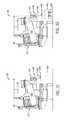
- FIG. 4is a rear elevation view of the proppant delivery system 10 having the dust collection assembly 12 positioned proximate the rear end 30 of the cradle 16 .
- the containers 18 arranged in a side-by-side configuration along the cradle 16are shown in phantom for clarity.
- the manifold 48is shown in phantom for clarity.
- the air mover 28is arranged closer to the rear end 30 of the cradle 16 than the container 18 positioned proximate the rear end 30 of the cradle 16 .
- the containers 18can be accessed from both sides of the cradle 16 , thereby improving access for maintenance, inspection, and the like.
- the manifold 48is shown with connections 60 arranged substantially linearly and proximate the distal end 32 of the cradle 16 .
- the connections 60enable the tubes 46 to couple to the manifold 48 , and thereby provide a flow path for the air having the dust particles to travel away from the blender hopper 20 , through the manifold 48 , and to the air mover 28 .
- the connections 60may be positioned along any portion of the manifold 48 and in any reasonable configuration to enable the tubes 46 to couple to the manifold 48 .
- the connections 60are positioned facing the plane of the page.
- the connections 60may be positioned at any circumferential position around the manifold 48 to enable quick and easy connections between components of the dust collection assembly 12 .
- the illustrated embodimentincludes conduit supports 62 coupled to a shroud arranged upstream of the chute 24 .
- the conduit supports 62support the conduit 44 (e.g., the tubes 46 ) extending from the manifold 48 to the hood assembly 42 .
- the conduit supports 62support the conduit 44 to block movement and maintain an open flow path along the conduit 44 .
- the conduit supports 62can block impingement along the conduits 44 , thereby facilitating an open flow path between the air mover 28 and the hood assembly 42 .
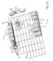
- FIG. 5is a top plan view of an embodiment of the proppant delivery system 10 and the dust collection assembly 12 . It is appreciated that several components are shown in phantom for clarity.
- the conduit 44couples the air mover 28 to the hood assembly 42 .
- tubing 70couples to the air mover 28 to the manifold 48 , which extends along the cradle length 40 .
- the tubes 46couple to the manifold 48 and to the hood assembly 42 , thereby forming a flow path between the air mover 28 and the hood assembly 42 .
- the manifold 48is positioned beneath the cradle 16 .
- the manifold 48is positioned within a front beam 72 and a rear beam 74 of the cradle 16 . As a result, the manifold 48 is away from a walking area around the cradle 16 , thereby enabling access to the containers 18 and decreasing the amount of equipment at ground level at the well site 14 .
- the tubes 46are arranged such that a pair of tubes extends along a rear side 76 of the chute 24 and a pair of tubes extends over the cradle and to a front side 78 of the chute 24 .
- a pair of tubesextends along a rear side 76 of the chute 24 and a pair of tubes extends over the cradle and to a front side 78 of the chute 24 .
- different configurations of the tubes 46may be utilized to form the flow path between the hood assembly 42 and the air mover 28 .
- FIG. 6is a top plan view of an embodiment of the dust collection assembly 12 supporting two proppant delivery systems 10 a , 10 b according to another embodiment of the present invention.
- multiple proppant delivery assemblies 10can be utilized to deliver proppant to a single blender hopper 20 .
- each of the proppant delivery systems 10 a , 10 bmay utilize the air mover 28 to draw air away from the blender hopper 20 via respective hood assemblies 42 a , 42 b.
- the manifold 48is positioned below the cradle 16 a of the proppant delivery assembly 10 a .
- This manifold 48is particularly selected such that the size of the manifold 48 can accommodate the air flow from both hood assemblies 42 a , 42 b .
- the cradle 16 b of the proppant delivery assembly 10 bdoes not have a manifold arranged below the cradle 16 .
- the tubes 46 b extending from the hood assembly 42 bare arranged to couple to the tubes 46 a .
- the dust particles removed via the hood assembly 48 bare transported through the tubes 46 b , into the tubes 42 a , toward the manifold 48 , and to the air mover 28 via the suction pressure generated by the air mover 28 .
- each hood assembly 42 a , 42 bis coupled to the respective chute 24 a , 24 b to be positioned above the blender hopper 20 to remove dust particles formed from the movement and settling of fracking proppant being dispensed from the containers 18 .
- the hood assemblies 42 a , 42 bare in contact with one another over the blender hopper 20 .
- the hood assemblies 42 a , 42 bare independently moveable via movement of the respective chutes 24 a , 24 b.
- FIG. 7is a partial perspective view of the proppant delivery system 10 positioned to deliver proppant to the blender hopper 20 according to an embodiment of the present invention.
- the container 18is positioned on a top surface 90 of the cradle 16 .
- the top surface 90positions the container 18 above the proppant mover 22 to receive the proppant 92 dispensed from the container 18 via an opening 94 at a bottom 96 of the container 18 .
- the proppant 92flows from the container 18 along inclined surfaces 98 and onto a surface of the proppant mover 22 for transportation to the blender hopper 20 via the chute 24 .
- the container 10is substantially box-shaped and has four walls 100 extending between corner posts 102 in the horizontal direction and a top post 104 and a bottom post 106 in the vertical direction. While FIG. 7 shows one wall 100 of the container 18 , it is appreciated that the other walls 100 are substantially similar to the illustrated wall 100 .
- the walls 100include a cage-like structural support 108 having vertical support bars 110 and horizontal support bars 112 arranged in a lattice-type configuration to provide structural support to the walls 100 when filled with the proppant 92 . Because proppant 92 is a highly-dense, granular material, little interstitial space remains between grains of the proppant 92 when the proppant 92 is loaded into the container 18 .
- the structural support 108provides strength and support to the walls 100 to stop bulging and/or deformation of the walls 100 when filled with proppant 92 .
- the structural integrity of the container 18is improved, thereby improving safety during transportation and also enabling reuse of the containers 18 when the proppant 92 is dispensed from the containers 18 .
- the proppant 92flows out of the opening 94 along inclined surfaces 98 .
- the angle of the inclined surfaces 92is particularly selected to enhance the emptying of the container 18 .
- the inclined surfaces 98are positioned approximately 30 degrees to 45 degrees relative to the bottom 96 .
- the inclined surfaces 98may be any angle relative to the bottom 96 to enhance emptying of the container 18 through the opening 94 .
- the container 10includes a gate 114 arranged at the bottom 96 and positioned to block or enable flow through the opening 94 .
- the gate 114is configured to couple to an actuator (e.g., hydraulic, electric, pneumatic) to drive movement of the gate 114 between an open position and a closed position.
- an actuatore.g., hydraulic, electric, pneumatic
- the orientation of the gate 114 when coupled to the actuatorsmay be utilized to properly align the containers 18 on the cradle 16 . That is, the gate 114 may be arrange such that the gate 114 only aligns with the actuator when the container 18 is placed on the cradle 16 in a desirable configuration.
- the proppant 92flows out of the container 18 along the inclined surfaces 98 through the opening 94 and onto a proppant mover top surface 120 .
- the proppant mover top surface 120receives and supports the proppant 92 as the proppant mover 22 takes the proppant 92 away from the container 18 and toward the blender hopper 20 .
- the proppant mover 22is a conveyor 122 (e.g., an endless conveyor) extending beyond the length 40 of the cradle 16 and arranged on one or more rollers 124 that underlies the top surface 90 of the cradle 16 .
- the conveyor 122carries the proppant 92 away from the containers 18 along an inclined section 126 to empty into the chute 24 .
- the conveyor 122turns over to direct the proppant 92 off of the conveyor 122 and into the chute 24 .
- the conveyor 122flips over at the chute 24 such that the surface traveling along the top of the rollers closest to the containers 18 becomes the surface traveling along the bottom of the rollers closest to the ground plane.
- the inclined section 126extends above the top surface 90 of the cradle 16 .
- the conveyor 122includes one or more projections 128 extending upward from the top surface 120 .
- the projections 128can include walls, nubs, ridges, or the like to facilitate receiving and supporting the proppant 92 as the proppant 92 contacts the conveyor 122 after it is dispensed from the containers 18 .
- the inclined section 126is covered by a shroud 130 that extends along a length 132 of the inclined section 126 .
- the shroud 130blocks dust particles formed due to the movement of the proppant 92 from entering the air, thereby potentially being inhaled by workers or entering and damaging auxiliary equipment.
- a catch box 140is coupled to a bottom surface 142 of the shroud 130 and arranged downstream of the chute 24 , relative to the movement of the proppant mover 22 .
- the catch box 140is fluidly coupled to the inclined section 126 via an opening in the bottom surface 142 forming a flow path between the shroud 130 and the catch box 140 .
- the chute 24is coupled to the shroud 130 via a proppant chamber 144 positioned between the shroud 130 and the chute 24 .
- the proppant chamber 144receives and directs the proppant 92 toward the chute 24 .
- the proppant chamber 144further serves to block dust particles from entering the air due to the enclosed nature of the proppant chamber 144 . As a result, dust particles formed in the proppant chamber 144 will settle onto the chute 24 , where the dust particles can be captured by the dust collection assembly 12 .
- the chute 24is pivotally coupled to the proppant chamber 144 at an attachment plane 146 .
- the chute 24is directable because the chute 24 can revolve about the attachment plane 146 (e.g., about an axis extending through and perpendicular to the attachment plane 146 ) to adjust the location in the blender hopper 20 where the proppant 92 is directed.
- the attachment plane 146e.g., about an axis extending through and perpendicular to the attachment plane 146
- the chute 24is coupled to the hood assembly 42 along a back wall 150 of the hood assembly 42 . Accordingly, the proppant 92 flows out of the chute 24 and through the hood assembly 42 to enter the blender hopper 20 .
- the tubes 46extend from a top 152 of the hood assembly 42 to capture the dust particles formed by the proppant 92 flowing into the blender hopper 20 and to remove a volume of air containing the dust particles.
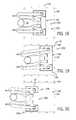
- FIG. 8is a perspective view of the hood assembly 42 of the dust collection assembly 12 positioned in association with the blender hopper 20 according to an embodiment of the present invention.
- the hood assembly 42overlays the blender hopper 20 and is positioned about an outlet of the chute 24 to capture dust particles formed by the movement and settling of the proppant 92 .
- the hood assembly 42includes a first hood section 154 , a second hood section 156 , and a third hood section 158 .
- the first hood section 154is a substantially enclosed area formed by the back wall 150 , a front wall 160 , and sidewalls 162 , 164 that substantially surrounds the chute 24 outlet.
- the chute 24is coupled to the back wall 150 and the proppant 92 flows into the enclosed area formed by the first hood section 154 as the proppant 92 flows toward the blender hopper 20 .
- the top 152includes a pair of dust receptacles 166 coupled to tubes 46 to direct the dust particles away from the blender hopper 20 and toward the air mover 28 via the suction pressure generated by the air mover 28 . While the illustrated embodiment includes two dust receptacles 166 , in other embodiments there can be 1, 3, 4, 5, or any suitable number of dust receptacles extending from the top 152 of the first hood section 154 .
- the first hood section 154is arranged to capture dust particles from at least a first volume 168 at least partially defined by the back wall 150 , the first wall 150 , the sidewalls 162 , 164 , and a bottom plane 170 (e.g., planar bottom surface) of the hood assembly 42 .
- the second hood section 156is positioned adjacent to the first hood section 154 and proximate the blender hopper 20 .
- the second hood section 156is arranged to capture dust particles in a second volume 172 at least partially defined by the bottom plane 170 of the hood assembly 42 and a pair of dust receptacles 174 .
- the dust receptacles 174are coupled to a dust enclosure 176 extending upward toward the top 152 of the first hood section 154 .
- the dust enclosure 176includes sloped walls 178 extending upward and converging on the tube 46 . In this manner, dust captured by the dust receptacles 174 is channeled upward through the dust enclosure 176 and into the tube 46 .
- the area around the dust receptacles 174is substantially open, thereby enabling inspection into the second volume 172 .
- the second hood section 15is coupled to the first hood section 154 via a support bracket 180 .
- the support bracket 180positions the second hood section 156 such that the dust receptacles 174 are substantially flush with the bottom plane 170 .
- the second hood section 156is positioned to capture dust particles that disperse out and away from the first hood section 154 and/or dust particles formed by the inclusion of the proppant 92 flowing out of the chute 24 .
- the third hood section 158is positioned adjacent the first hood section 154 and substantially opposite the second hood section 156 . That is, the second and third hood sections 156 , 158 are substantially symmetrical about the first hood section 154 . Accordingly, the third hood section 158 is arranged to capture dust particles that disperse out and away from the first hood section 154 , in a similar manner to the second hood section 156 . It should be appreciated that the first hood section 154 partially obscures the view of the third hood section 158 in the illustrated embodiment.
- the third hood section 158includes dust receptacles 182 and a dust enclosure 184 arranged in the manner illustrated for the second hood section 156 .
- the hood assembly 42is smaller than the blender hopper 20 . That is, a length 186 and a depth 188 defining a capture area 190 of the hood assembly 42 is smaller than a surface area 192 of the blender hopper 20 defined by a hopper length 194 and a hopper depth 196 . Therefore, the hood assembly 42 can be moved around the blender hopper 20 to capture dust particles that are formed due to the settling and movement of the proppant 92 . Moreover, the chute 24 can be moved to direct the proppant 92 to different areas of the blender hopper 20 to ensure even distributions in the blender hopper 20 . Furthermore, while the illustrated embodiment depicts the hood assembly 42 has being smaller than the blender hopper 20 , in other embodiments they may be substantially the same size or the hood assembly 42 may be larger than the blender hopper 20 .
- the chute 24is coupled to the back wall 150 of the hood assembly 42 .
- the slots 198 positioned on the top 152are configured to receive forks of a forklift to enable lifting and movement of the hood assembly 42 . Because the slots 198 are coupled to the top 152 , movement via the slots 198 leads to movement of the entire hood assembly 42 because the second and third hood sections 156 , 158 are coupled to the first hood section 154 via the support bracket 180 . In this manner, the hood assembly 42 can be positioned on the chute 24 at the well site 14 , thereby reducing the equipment coupled to the chute 24 during transportation between well sites 14 . Moreover, the hood assembly 42 can be adapted to be used at other locations (e.g., such as transloading sites where the proppant 92 is loaded into the containers 18 ) because of the ease of removability via the slots 198 .
- FIG. 8also illustrates an embodiment of the tubes 46 extending from the hood assembly 42 and toward the manifold 48 .
- a pair of tubes 46extends around the front side 78 of the chute 24 and a pair of tubes 46 extends around the rear side 76 of the chute 24 .
- the tubes 46can be organized based on the location where the tubes 46 are coupled to the hood assembly 42 .
- the tubes 46 coupled to the first hood section 154include bends 200 that conform to the chute 24 . The bends 200 enable a smaller footprint for the system because the tubes 46 are positioned closer to the chute 24 than tubes without bends 200 . As a result, the tubes 46 are more streamlined.
- the tubes 46are easier to install because the bends 200 provide an indication as to which tube 46 couples to which dust receptacle of the hood assembly 42 . As a result, the duration to install the system may be reduced, thereby improving efficiencies at the well site 14 .
- the hood assembly 42includes a curtain 202 extending downwardly from the bottom plane 170 toward the blender hopper 20 .
- the curtain 202is formed from flexible sheets (e.g., plastic) to form at least a portion of the first volume 168 , the second volume 170 , and a third volume 204 .
- the curtain 202may be a single unit having no gaps.
- the curtain 202may include multiple strips or sections that are independently moveable from one other.
- the curtain 202blocks the dust particles from dispersing out and away from the first, second, and third volumes 168 , 170 , 204 , thereby enhancing the collection by the hood assembly 42 .
- the hood assembly 42may be lowered into the blender hopper 20 such that the curtain 202 is in contact with the proppant 92 positioned within the blender hopper 20 .
- the dust particleswill be contained within the first, second, and third volumes 168 , 170 , 204 as the proppant 92 flows from the chute 24 to the blender hopper 20 .
- the curtain 202extends about a perimeter 206 of the capture area 190 to substantially enclose the dust particles within the first, second, and third volumes 168 , 170 , 204 .
- FIG. 9is a side elevation view of the hood assembly 42 according to an embodiment of the present invention.
- the chute 24is coupled to the angled back wall 150 to direct the proppant 92 flowing through the chute 24 through the hood assembly 42 .
- the front wall 160is angled and converges toward the back wall 150 at the top 152 .
- the area at the top 152 of the first hood section 142is smaller than the area at the bottom plane 170 .
- the dust enclosure 184is formed by sloped walls 178 at converge toward the tube 46 , thereby directing the collected dust particles out of the dust receptacles 182 and toward the air mover 28 .
- the third hood section 158includes the pair of dust receptacles 182 arranged in a spaced apart relationship.
- the dust receptacles 182extend downwardly from the dust enclosure 184 to capture dust particles in the third volume 204 .
- the dust receptacles 182are substantially cylindrical tubular members that have an enlarged opening 220 positioned at a bottom thereof.
- the cross-sectional area of the dust receptacles 182decreases from the opening 220 upward to the dust enclosure 184 .
- the illustrated embodimentincludes a reduced diameter on the dust receptacles 182 , in other embodiments the diameter may increase or remain substantially constant.
- the first hood section 154is defined at least in part by the side walls 162 , 164 , the top 152 , and the front wall 160 . It should be noted that the back wall 150 also defines the first hood section 154 , at least in part, but is not visible in the depicted view.
- the hood assembly 42is lowered into the blender hopper 20 such that the curtain 202 is in contact with the proppant 92 in the blender hopper, or such that the curtain 202 is closely positioned to the proppant 92 in the blender hopper.
- the first volume 168 being acted on by the suction force through the dust receptacles 166may be defined at least in part by the first hood section 154 and the curtain 202 .
- the second and third hood sections 156 , 158are positioned on opposite sides of the first hood section 154 to capture dust particles formed when the proppant 92 flows through the first hood section 154 .
- each of the second and third hood sections 156 , 158includes dust receptacles 174 , 182 and dust enclosures 176 , 184 , respectively.
- suction pressure from the air moverdraws a volume of air into each of the dust receptacles 174 , 182 , the volume of air is directed toward the respective dust enclosure 176 , 184 and toward the tubes 46 . In this manner, dust particles can be removed from the second and third volumes 172 , 204 .
- FIG. 11is a rear elevation view of the hood assembly 42 according to an embodiment of the present invention.
- the chute 24is coupled to the back wall 150 such that proppant 92 flowing through the chute 24 enters the first hood section 154 .
- the chute 24is substantially centered in the back wall 150 such that the proppant 92 exiting the chute 24 will be uniformly spread through the first hood section 154 .
- the curtain 202extends about the perimeter 206 as illustrated in FIG. 11 . In this manner, the first, second, and third volumes 168 , 172 , 204 can be substantially sealed off, thereby improving the suction pressure generated by the air mover 28 .
- FIG. 12is a top plan view of the hood assembly 42 and the routing of the tubes 46 , according to an embodiment of the present invention.
- the hood assembly 42is substantially symmetrical about the first hood section 154 , in the illustrated embodiment. Accordingly, the dust particles may be captured uniformly in the blender hopper 20 .
- the back wall 150 and front wall 160converge at the top 152 where the dust receptacles 166 are coupled to the tubes 46 to direct the dust particles away from the hood assembly 42 and toward the air mover 28 .
- the top 152extends between the sidewalls 162 , 164 to span across the first hood section 14 .
- the dust receptacles 174 , 182are arranged on the respective dust enclosures 176 , 184 of the second and third hood sections 156 , 158 .
- the second and third hood sections 156 , 158each include a pair of dust receptacles 174 , 182 arranged in a spaced relationship along the hood depth 188 . In this manner, the suction pressure generated by the air mover 28 is distributed over the hood depth 188 of each of the second and third hood sections 156 , 158 to facilitate capture and removal of the dust particles formed by the movement and settling of the proppant 92 .
- the tube connections 240are substantially aligned along the hood length 186 . That is, the locations where the tubes 46 interact with the hood assembly 42 are substantially aligned and centered relative to the hood length 186 and the hood depth 188 . As a result, the suction pressure generated by the air mover 28 is directed toward a central portion of the hood assembly 42 . As described above, the first hood section 154 converges toward the top 152 and the dust enclosures 176 , 184 also converge upward toward the tubes 46 . Accordingly, the respective cross-sectional areas are reduced as the captured dust particles move upward toward the tubes 46 , thereby increasing the force enacted on the dust particles by the suction pressure. In this manner, the dust particles are captured and removed from the area proximate the blender hopper 20 , thereby decreasing the likelihood that the dust particles are inhaled by operations personnel or interact with auxiliary equipment.
- the tubes 46are routed in pairs around the front side 78 of the chute and the rear side 76 of the chute. As shown, the tubes are generally parallel until the bends 200 direct the inner tubes 46 a toward the connections 240 on the first hood section 154 . Routing the tubes 46 in pairs simplifies maintenance and inspection because an operator can quickly and easily identify which tubes 46 are coupled to which sections of the hood assembly 42 . In this manner, the dust particles captured in the hood assembly 42 can be removed and carried toward the air mover 28 via the tubes 46 .
- FIG. 13is a bottom plan view of the hood assembly 42 according to an embodiment of the present invention.
- the chute 24connections to the hood assembly 42 along the back wall 150 , thereby directing proppant 92 flowing through the chute 24 through the first hood section 154 before being deposited into the blender hopper 20 .
- screens 250are positioned within the first hood section 154 .
- the screens 250are positioned to block grains of proppant 92 from entering the dust receptacles 166 .
- the air mover 28may be configured to operate at a suction pressure sufficient to lift grains of proppant 92 from the blender hopper 20 .
- the screens 250can be sized to block the grains of proppant 92 from entering the dust receptacles 166 , thereby limiting the quantity of proppant 92 removed from the blender hopper 20 .
- the screens 250may not be included in the hood assembly 42 .
- the air mover 28may be operated at a suction pressure sufficient to capture dust particles, which are smaller and weigh less than the grains of proppant 92 , while not significantly impacting the grains of proppant 92 .
- the dust receptacles 174 , 182 of the second and third hood sections 156 , 158are positioned closer to the bottom plane 170 than the dust receptacles 166 of the first hood section 154 . Moreover, the second and third hood sections 156 , 158 are not fully enclosed, like the first hood section 154 , and therefore the dust particles are not funneled toward the second and third hood sections 156 , 158 . However, by positioning the dust receptacles 174 , 182 closer to the blender hopper 20 , the second and third hood sections 156 , 158 can capture dust particles that are formed by the movement and settling of the proppant 92 flowing through the chute 24 .
- the dust particlesmay disperse outwardly from the first hood section 154 as the proppant 92 contacts the level of proppant 92 in the blender hopper 20 .
- the second and third hood sections 156 , 158are therefore positioned to capture the dust particles that move away from the first hood section 154 , thereby removing dust particles from the air to reduce the risk of inhalation or contact with auxiliary equipment.
- FIG. 14is a partial sectional view of the hood assembly 24 taken along line 14 - 14 of FIG. 8 positioned in association with the blender hopper 20 to collect dust particles from the blender hopper 20 according to an embodiment of the present invention.
- a bottom plane 260 of the curtain 202is positioned to overlay an opening 262 of the blender hopper 20 to substantially block the dust particles from escaping after being formed due to the movement and settling of the proppant 92 .
- the proppant 92flows out of the chute 24 and into the blender hopper 20 through the first hood section 154 .
- dust particles 264can form.
- the dust particles 264have a smaller diameter than the grains of proppant 92 and weigh less, thereby enabling the suction pressure of the air mover 28 to capture the dust particles 264 and remove them from the blender hopper 20 .
- the air mover 28directs an air flow 266 (represented be the arrows) over a flow path 268 arranged over the blender hopper 20 .
- the flow path 268is at least partially defined by the curtain 202 .
- the air flow 266is a suction force that draws air out of the blender hopper and up into the hood assembly 42 .
- the air flow 266is a vacuum force that moves air in the flow path 268 in a direction substantially opposite the direction of the proppant 92 flowing into the blender hopper 20 from the chute 24 .
- the air flow 266draws the dust particles 264 toward the first, second, and third hood sections 154 , 156 , 158 .
- the air flow 266is positioned over the flow path 268 to capture dust particles 264 suspended in the first, second, and third volumes 168 , 170 , 204 .
- the air flow 266pulls the dust particles 264 into the dust receptacles 166 , 174 , 182 and through the hood assembly 42 to enter the tubes 46 . Thereafter, the tubes 46 direct the air flow 266 toward the air mover 28 and away from the blender hopper 20 .
- the vacuum pressure generated by the air mover 28is designed to carry the dust particles 264 produced by the movement and settling of the proppant 92 without significantly impacting the proppant 92 .
- the vacuum pressureis designed to lift the dust particles 264 away from the proppant 92 while also limiting or substantially restricting the quantity of proppant 92 lifted away from the blender hopper 20 .
- the air flow 266is designed to be sufficient to collect the dust particles 264 and also significantly reduce the risk of lifting the proppant 92 .
- the air mover 28can include one or more fans or blowers driven by the engine 52 to draw a volume of air away from the blender hopper 20 (e.g., via the conduit 44 ) and toward the air mover 28 .
- the pressure in front of the fan bladese.g., downstream of the fan blades
- the pressure in front of the fan bladesis reduced, thereby drawing air across the fan blades.
- energyis added to the air, thereby increasing the velocity of the air. In this manner, air is removed from downstream of the fan and directed toward the fan.
- the air mover 28includes the conduit 44 to couple the air mover 28 to the hood assembly 42 .
- fluide.g., gas, liquid, solids, mixtures thereof
- conduit 44to couple the air mover 28 to the hood assembly 42 .
- fluide.g., gas, liquid, solids, mixtures thereof
- static pressuree.g., the pressure that the air mover 28 overcomes in order to generate the suction pressure.
- the air mover 28is designed to generate a sufficient suction pressure to overcome the static pressure (e.g., line losses) and also capture and remove the dust particles 256 .
- the fanis designed to operate at a given flow rate for a given static pressure.
- the air mover 28e.g., the fan of the air mover 28
- the air mover 28is rated to operate at approximately 1699 cubic meters per hour (m3/h) at 431.8 millimeters water gauge (mmWG) (1000 cubic feet per minute (CFM) at 17 inches water gauge (inWG) or 286.2 cubic meters per minute (m3/min) at 4234.5 Pascals (Pa)).
- mmWGmillimeters water gauge
- CFMcubic feet per minute
- inWGinWG
- m3/min286.2 cubic meters per minute
- the air mover 28is rated to operate at approximately 20390 m3/h at 297.18 mmWG (12000 CFM at 11.7 inWG or 339 m3/min at 2914.34 Pa).
- the flow rate and the static pressureare inversely proportional, such that at the static pressure, and therefore the pressure drop in the system, decreases, the flow rate increases.
- the routing configuration of the conduit 44may be adjusted at the well site to lower the static pressure, thereby increasing the flow rate of the system.
- the static pressurecan also be a property of the temperature, elevation, atmospheric pressure, and the like of the well site. Accordingly, well sites located at higher elevations (e.g., in mountainous regions) may have a lower atmospheric pressure, and thereby a lower static pressure. Moreover, well sites located at lower elevations may have a higher atmospheric pressure, and thereby a higher static pressure. In this manner, the system may be adjusted based on the location of the well site, the environmental conditions at the well site, and the desired operating parameters of the well site.
- the suction pressure(e.g., vacuum pressure, vacuum force, suction force) generated by the air mover 28 is sufficient to capture and remove the dust particles 264 generated by the movement and settling of the proppant 92 while not lifting or carrying the proppant 92 up and away from the blender hopper 20 .
- the proppant 92may have a density between 1.5 grams per cubic centimeter (g/cm3) and 4 g/cm3.
- the proppant 92can have a mesh size of 20/40 and have an average proppant diameter of 0.69 millimeters (mm).
- the proppant 92may be spherical particles, having a volume defined by (4/3)(pi)(r)3, where r is the radius of the spherical shape. Accordingly, the grains of proppant 92 can have a mass in the range of approximately 0.25801 milligrams (mg) and 0.688027 mg. However, it should be appreciated that in other embodiments the grains of proppant 92 can have different densities and different diameters, which could have masses different than the range specified above. For example, larger, denser grains would have a larger mass, while smaller, less dense grains would have a smaller mass.
- pressureis defined as force of area.
- the forcecan be defined as the mass of the grains of proppant over an area.
- the proppant 92not be referred to as a single grain, but instead, as a layer of grains evenly distributed over a plane.
- the calculations contained hereinmay be utilized on any number of proppant grains to determine a pressure sufficient to lift the grains from a resting position.
- the hood assembly 42can have dimensions of approximately 1.22 meters (m) by 1.22 m (approximately 4 feet by 4 feet).
- the surface areais approximately 1.44 square meters (m2).
- the surface area of the proppant positioned on the plane having a surface area of approximately 1.44 m2is different.
- the proppant grains having an average diameter of 0.69 mm as described aboveapproximately 3,118,756 grains of proppant 92 can be positioned under the hood assembly 42 having the surface area of approximately 1.44 m2.
- the surface area of the proppantmay be approximated by calculating of half of the surface area of a sphere, because approximately one half of the surface area will be pointed downwards.
- the pressure range for the average density(e.g., 1.5 g/cm3 to 4 g/cm3) can be determined.
- the weight of the proppant particlesmay be calculated by multiplying the mass of the particles by the number of particles and by the force due to gravity (e.g., 9.81 m/s2).
- the calculated weightis divided by the calculated area, yielding a pressure of 3.38 Pa.
- the pressureis 9.025 Pa. Therefore, for suction pressures above the static pressure of less than approximately 3.38 Pa, the grains of proppant 92 in the blender hopper 20 will not be carried away.
- the suction pressures above the static pressuremay be within a range from approximately 3.38 Pa to 9.025 Pa.
- the dust particles 264which are smaller and lighter than the proppant 92 , will be captured and removed from the volume of air proximate the blender hopper.
- the above mentioned pressuresmay be modified due to operating conditions, such as temperature, atmospheric pressure, proppant size, proppant density, conduit 44 configurations, filter element properties, and the like.
- the above-calculated pressuresare indicative of pressures above the static pressure utilized to overcome the line losses present in the system.
- the tubes 46couple to the hood assembly 42 at the tube connections 240 .
- the tube connections 240are substantially aligned. That is, the tube connections 240 are at approximately the same elevation relative to the bottom plane 170 of the hood assembly 42 .
- the tube connections 240do not need to be aligned in order for the tubes 46 to remove the dust particles 264 from the blender hopper 20 .
- the sloped walls 178 of the dust enclosures 176 , 184converge toward the tube connections 240 to thereby decrease the cross-sectional area of the dust enclosures 176 , 184 .
- the force generated by the air mover 28 via the air flow 266is increased before the air flow 266 enters the tubes 46 . Accordingly, the larger force acting on the dust particles 264 will facilitate capture and transportation of the air flow 266 to the air mover 28 .
- FIG. 15is a sectional view of the hood assembly 24 taken along line 15 - 15 of FIG. 8 .
- the arrowdepicts the proppant flow direction 280 through the chute 24 .
- the proppant 92flows through the chute 24 after being received from the proppant mover 22 .
- the chute 24is angled downward, thereby utilizing gravity to drain into the blender hopper 20 .
- the chute 24is positioned such that an angle 282 of the chute relative to the back wall 150 is approximately 90 degrees. In other words, the chute 24 is arranged substantially perpendicular to the back wall 150 .
- the chute 24may be positioned at other angles relative to the back wall 150 (e.g., 45 degrees, 60 degrees, 75 degrees, etc.) to accommodate design conditions.
- the screen 250is positioned to extend upward along the side wall 162 . In this manner, the screen 250 may block grains of proppant captured by the air flow 266 from traveling upward into the corners of the first hood section 154 . Once captured, the dust particles 264 are entrained in the air flow 266 moving in an air flow direction 284 . As shown, the air flow direction 284 is substantially opposite the proppant flow direction 280 . In other words, the air flow direction 284 is out of and away from the blender hopper 20 , while the proppant flow direction 280 is toward and into the blender hopper 20 .
- FIG. 16is a sectional view of the hood assembly 42 taken along line 16 - 16 of FIG. 8 .
- the dust enclosure 176is shown with the air flow 266 directing the air from the flow path 268 upward to the tubes 46 .
- the dust enclosure 176receives the air removed from the second volume 172 by the air flow 266 .
- the pair of dust receptacles 174are substantially aligned with the bottom plane 170 of the hood assembly 42 to capture dust particles formed in and around the second volume 172 .
- the arrows 266representing the air flow
- air from the flow path 268is captured by the air flow 266 such that dust particles positioned in the air are directed toward the second hood section 156 .
- the dust receptacles 174are coupled to the dust enclosure 176 to direct the air flow 266 toward the air mover 28 in the air flow direction 284 via the tubes 46 . In this manner, the dust particles 264 can be removed from proximate the blender hopper 24 via the hood assembly 42 .
- the sloped walls 178 of the dust enclosure 176are positioned to reduce the cross-sectional area of the dust enclosure 176 and direct the air flow 266 toward the tube connections 240 and the tubes 46 .
- the sloped walls 178converge toward the tube connections 240 toward a center of the dust enclosure 176 , thereby funneling the air flow 266 toward the tubes 46 .
- the illustrated embodimentincludes the second hood section 156
- the third hood section 158is substantially a mirror-image. Accordingly, the features present in the second hood section 156 are also present in the third hood section 158 .
- FIG. 17is a schematic diagram of the conduit 44 coupling the air mover 28 to the hood assembly 42 , according to an embodiment of the present invention.
- the air mover 28is positioned to draw air away from the hood assembly 42 and the catch box 140 via a generated suction pressure.
- the air flow 266moves in the air flow direction 284 away from the hood assembly 42 and the catch box 140 and toward the air mover 28 .
- the tubes 46couple the hood assembly 42 and the catch box 140 to the manifold 48 to direct the air flow 266 back to the air mover 28 . It should be appreciate that while the illustrated embodiment depicts four tubes 46 extending from the hood assembly 42 to the manifold 48 , in other embodiments more or fewer tubes 46 may be utilized to enable the air flow 266 to enter the manifold 48 .
- FIG. 18is a top plan view of the hood assembly 42 in a first position 290 adjacent and overlying the blender hopper 20 according to an embodiment of the present invention.
- the capture area 190is smaller than the blender hopper surface area 192 .
- the hood assembly 42can move to different positions in the blender hopper 20 to evenly distribute the proppant 92 and to capture dust particles 264 formed by the movement and settling of the proppant 92 .
- FIG. 19a top plan view of the hood assembly 42 in a second position 292 is shown. In the illustrated embodiment, the second position 292 is different than the first position 290 .
- the second position 292is closer to a corner 294 of the blender hopper 20 than the first position 290 .
- the hood assembly 42can be moved in the blender hopper 20 to evenly distribute the proppant 92 and to capture dust particles 264 .
- a top plan view of the hood assembly 42 in a third position 296is shown. As shown, the hood assembly 42 is positioned at an opposite corner 298 from the corner 294 . In this manner, the hood assembly 42 can be continuously moved over the blender hopper 20 to distribute the proppant 92 and to capture dust particles 264 formed by the settling and movement of the proppant 92 .
- FIG. 21is a top plan view of the conduit 44 coupled to the hood assembly 42 .
- the tubes 46are coupled to the hood assembly 42 at the connections 240 .
- the air flow 266is directed through the tubes 46 and toward the manifold 48 .
- the manifold 48receives the air flow 266 and further directs the air flow 266 in the air flow direction 284 away from the hood assembly 42 and toward the air mover 28 .
- the tubes 46are supported by the conduit supports 62 (in phantom) arranged along the inclined section 126 .
- the conduit supports 62direct the tubes 46 to the front side 78 and the rear side 76 of the chute 24 . Accordingly, the tubes 46 are organized, thereby increasing the ease of maintenance or inspection of the tubes 46 .
- the tubes 46couple to the manifold 48 at the connections 60 . Accordingly, the air flow 266 in the tubes 46 is directed toward the manifold 48 for further delivery to the air mover 28 .
- the tubes 46are organized at the connections 60 to readily identify which tube 46 is connected to the first, second, and third hood sections 154 , 156 , 158 . Accordingly, during maintenance or inspection, operations personnel can easily identify potential blockages and/or concerns with the tubes 46 and the associated hood sections 154 , 156 , 158 .
- FIG. 22is a perspective view of the catch box 140 positioned on the bottom surface 142 of the inclined section 126 of the shroud 130 .
- the catch box 140is positioned below the proppant mover 22 to catch residual proppant that remains on the proppant mover 22 after being deposited into the chute 24 .
- the catch box 140has a substantially vertical side 310 arranged proximate the proppant chamber 144 and an inclined side 312 arranged proximate the inclined section 126 and opposite the vertical side 310 .
- the vertical side 310 and the inclined side 312direct residual proppant and dust particles 264 received by the catch box 140 downward toward a lower section 314 having an outlet 316 .
- the lower section 314is substantially cylindrical and coupled to the vertical side 310 and the inclined side 312 . Moreover, the lower section 314 is coupled to a first side panel 318 and a second side panel 320 , the second side panel being obscured in this view. In this manner, the catch box 140 includes an interior volume for receiving and storing residual proppant and dust particles 264 .
- the outlet 316is coupled to the tubes 46 for removal of the residual proppant and dust particles 264 stored within the catch box 140 .
- the outlet 316is coupled to the manifold 48 and is acted on by the vacuum pressure of the air mover 28 .
- the catch box 140is arranged to store the residual proppant for later manual removal after fracking operations are complete.
- the suction pressure generated by the air mover 28is not large enough to carry the proppant 92 .
- the catch box 140may be arranged to hold the residual proppant because the air flow 266 may not be sufficient to carry the proppant 92 .
- the air flow 266may be sufficient to remove the residual proppant from the catch box 140 .
- FIG. 23is a front elevational view of the catch box 140 arranged under the inclined section 126 .
- the tubes 46 coupled to the first hood section 154 , the second hood section 156 , and the third hood section 158are shown in phantom being supported by the conduit supports 62 .
- the vertical side 310includes an access port 330 .
- the tubes 46may be coupled to the access port 330 in order to provide a second flow path out of the catch box 140 , in addition to the outlet 316 arranged at the lower section 314 .
- the lower section 314has a lower width 332 that is greater than a catch box width 334 . As a result, the lower section 314 can distribute the residual proppant and dust particles 264 over a larger surface area, thereby enhancing the effectiveness of the vacuum pressure acting on the outlet 316 .
- the conduit supports 62are coupled to and extend away from the vertical side 310 .
- the catch box 140is utilized to support and route the tubes 46 between the manifold 48 and the first, second, and third hood sections 154 , 156 , 158 .
- the conduit supports 62 on the catch box 140position the tubes 46 above the lower section 314 and out of contact with the lower section 314 .
- the tubes 46may rest on the lower section 314 to provide further support.
- FIG. 24is a side elevational view of the catch box 140 positioned on the bottom surface 142 of the shroud 130 such that the catch box 140 is downstream of the chute 24 , relative to the direction of travel of the proppant mover 22 .
- the inclined side 312is positioned at an angle 340 with respect to the vertical side 310 . It is appreciated that by positioning the inclined side 312 at the angle 340 , residual proppant and dust particles 264 that enter the catch box 140 and contact the inclined side 312 will be directed downward toward the lower section 314 via gravity. As such, the residual proppant and dust particles 264 may be positioned proximate the outlet 316 for removal.
- the catch box 140is positioned downstream of the chute 24 , relative to the direction of travel of the proppant mover 22 .
- the proppant mover 22carries the proppant 92 in a first direction 342 toward the proppant chamber 144 and the chute 24 .
- the proppant mover 22is the endless conveyor 122 which turns over at a point and returns back toward the containers 18 in the second direction 344 .
- the catch box 140is positioned along the portion of the conveyor moving in the second direction 344 , and therefore is described as being downstream of the chute 24 .
- the catch box 140is coupled to the bottom surface 142 of the shroud 130 .
- coupling the catch box 140 to the bottom surface 142enables the residual proppant to fall off of the conveyor 122 as it moves in the second direction 344 , and thereby downward and into the catch box 140 .
- positioning the catch box 140 below the inclined section 126enables use of the catch box 140 is support the tubes 46 via the conduit supports 62 , thereby enhancing the routing of the tubes 42 around the inclined section 126 .
- the outlet 316extends out of the lower section 314 perpendicular to the plane of the page.
- the outlet 316is coupled to the tube 46 to direct the residual proppant and dust particles 264 positioned within the catch box 140 toward the manifold 48 via the suction pressure generated by the air mover 28 . That is, the residual proppant and dust particles 264 will be directed downward toward the lower section 314 via the vertical side 310 and the inclined side 312 .
- the suction pressure of the air mover 28removes the residual proppant and/or the dust particles 264 from the catch box 140 via the outlet 316 to be directed toward the air mover 28 . In this manner, the risk of exposure to proppant and dust particles 264 is reduced because the proppant and dust particles 264 remain contained within the shroud 130 and the catch box 140 after being deposited into the chute 24 .
- FIG. 25is a cross-sectional view of the catch box 140 receiving residual proppant 354 and dust particles 264 from the conveyor 122 taken along line 25 - 25 of FIG. 23 .
- the vertical side 310 , inclined side 312 , lower section 314 , second side panel 320 , and bottom surface 142 of the shroud 130at least partially define an interior volume 350 of the catch box 140 .
- an inlet 352is positioned proximate the junction between the chute 24 and the vertical side 310 . The inlet 352 fluidly couples the catch box 140 to the shroud 130 .
- residual proppant 354falls from a lower surface 356 of the conveyor 122 and into the catch box 140 .
- the lower surface 356describes the surface of the conveyor 122 as the conveyor 122 is traveling in the second direction 344 . In other words, the lower surface 356 is the surface of the conveyor 122 positioned closest to the ground plane.
- the residual proppant 354falls off of the lower surface 356 via the gravitational force acting on the residual proppant 354 as the conveyor 122 moves in the second direction 344 .
- the residual proppant 354 and dust particles 254settle and collect in the lower section 314 of the catch box 140 .
- the residual proppant 354may contact the inclined side 312 and be directed toward the lower section 314 .
- the residual proppant 354 and the dust particles 254are removed from the catch box 140 via the air flow 266 generated by the suction pressure of the air mover 28 .
- the tube 46is coupled to the outlet 316 to fluidly couple the air mover 28 to the catch box 140 via the manifold 48 . Accordingly, the residual proppant 354 and the dust particles 254 remain within the contained portions (e.g., shroud 130 , manifold 48 , catch box 140 ) of the system, thereby reducing the risk of exposure to fracking site operations personnel.
- FIG. 26is a partial side elevation view of proppant 92 being deposited into the catch box 140 , according to an embodiment of the present invention.
- the catch box 14is arranged on a bottom surface 142 of the shroud 130 to catch dust particles 264 and proppant 92 after the conveyor 122 turns over to deposit the proppant 92 into the proppant chamber 144 .
- the conveyor 122receives the proppant 92 discharged from the containers 18 on the top surface 120 .
- the conveyor 122moves the proppant 92 away from the containers 18 and up the inclined section 126 .
- the conveyor 122turns over such that the top surface 120 is no longer on top of the rollers 124 .
- the top surface 120becomes the lower surface 356 that substantially faces a ground plane.
- the proppant 92 on the top surface 120falls off of the conveyor 122 at the apex 400 and into the proppant chamber 144 to the chute 24 .
- residual proppant 354remains on the top surface 102 .
- dust particles 264may form in the proppant chamber 144 due to the movement and settling of the proppant 92 .
- the catch box 140is positioned on the bottom surface 142 of the shroud 130 downstream of the apex 400 .
- the inlet 352 between the shroud 130 and the proppant chamber 144provides access to the catch box 140 .
- the residual proppant 354 remaining on the conveyor 122is directed toward the catch box 140 via the positioning of the catch box 140 at the location where the conveyor 122 turns over.
- the catch box 140is positioned downstream of the apex 400 where the top surface 120 becomes the lower surface 356 .
- the gravitational force acting on the residual proppant 354drives the residual proppant 354 to fall off of the conveyor 122 and into the catch box 140 .
- dust particles 264 forming at the proppant chamber 144can settle toward the inlet 352 , thereby being captured in the catch box 140 . In this manner, the residual proppant 354 and dust particles 264 may be captured before the lower surface 356 returns down the inclined section 126 and toward the containers 18 .
- FIG. 27is a cross-sectional view of the hood assembly 42 arranged over the blender hopper 20 in which the air flow 266 traveling through the conduit 44 is illustrated.
- the hood assembly 42is arranged proximate and overlying the blender hopper 20 .
- the hood assembly 42is smaller than the blender hopper 20 , thereby enabling the hood assembly 42 to move without the blender hopper 20 to evenly distribute the proppant 92 .
- the hood assembly 42is coupled to and surrounds the chute 24 . As described above, the chute 24 receives the proppant 92 from the proppant mover 22 , as shown by the proppant flow direction 280 .
- the proppant 92is dispensed from the containers 18 positioned on the cradle 16 downward via gravity feed onto the proppant mover 22 .
- the proppant mover 22moves the proppant 92 away from the containers 18 and toward the chute 24 .
- the chute 24positioned to direct the proppant 92 into the blender hopper 20 .
- the hood assembly 42is positioned to capture dust particles 264 formed due to the movement and settling of the proppant 92 .
- the hood assembly 42directs the air flow 266 over the flow path 268 to capture the dust particles 264 and direct the dust particles 264 through the hood assembly 42 and into the tubes 46 .
- the tubes 46direct the air flow 266 toward the manifold 48 in the air flow direction 284 .
- the tubes 46are coupled to the manifold 48 at the connections 60 , thereby substantially joining the respective air flows 266 in each tube 46 . In this manner, the captured dust particles are directed away from the blender hopper 20 and toward the air mover 28 .
- the catch box 140is arranged on the bottom surface 142 of the inclined section 126 .
- the air flow 266acts on the catch box 140 to remove the residual proppant 354 and dust particles 264 that are collected therein via the tube 46 coupled to the outlet 316 .
- the tube 46is coupled to the manifold 48 , thereby transmitting the suction pressure generated by the air mover 28 .
- the tube 46receives the residual proppant 354 and the dust particles 264 from the catch box 140 and directs them toward the manifold 48 via the air flow 266 .
- the manifold 48directs the air flow 266 in the air flow direction 284 toward the air mover 28 and away from the blender hopper 20 .
- FIG. 28is a perspective view of the air mover 28 arranged at the rear end 30 of the cradle 16 .
- the engine 52is positioned proximate the air mover 28 to provide operational power to generate the suction pressure (e.g., vacuum pressure, suction force, vacuum force) that enables the hood assembly 42 to capture the dust particles 264 .
- the engine 52may be coupled to a fan that rotates via rotation of the engine 52 .
- the air mover 28is positioned on the skid 50 to enable movement between well sites and to optimize placement along the length 40 of the cradle 16 .
- the air mover 28is positioned at the rear end 30 .
- the air mover 28may be positioned closer to the distal end 32 . It is appreciated that positioning the air mover 28 closer to the hood assembly 42 may reduce the pressure drop along the conduit 44 (e.g., by shortening the length of the conduit 44 ), thereby reducing the static pressure and increasing the flow rate of the air mover 28 .
- the air mover 28is coupled to the manifold 48 via the tubing 70 .
- the tubing 70is flexible tubing (e.g., polymer tubing, flexible metal, etc.) to simplify installation of the system.
- the tubing 70can be positioned to curve under the cradle 16 to couple to the manifold 48 .
- the overall footprint of the systemmay be reduced at the well site 14 .
- FIG. 29is a side elevation view of the air mover 28 , according to an embodiment of the present invention.
- the air mover 28is positioned on the skid 50 to elevate the air mover 28 above the ground plane.
- the engine 52is positioned proximate the air mover 28 (e.g., compressor, fan) and provides operational power to the air mover 28 .
- the engine 52is a diesel powered engine.
- the engine 52may be gas powered or electric.
- the air mover 28includes a cover 420 which is removable to access filter elements within the air mover 28 . The filter elements block dust and debris from entering the moving parts of the air mover 28 , thereby improving longevity of the equipment.
- a duct connector 422is positioned on the air mover 28 to couple the tubing 70 between the air mover 28 and the manifold 48 . As shown, the duct connector 422 includes a removable cover to block access to the interior workings of the air mover 28 when the air mover is not in use, such as during transportation or maintenance.
- the air flow 266travels toward the air mover 28 via the conduit 44 .
- the filter elementsare utilized to filter out the captured dust particles 264 and residual proppant 354 .
- the air mover 28includes a discharge 424 to remove the dust particles 264 and the residual proppant 354 from the system.
- the discharge 424can be coupled to a container to receive the dust particles 264 and the residual proppant 354 for disposal.
- the air mover 28includes a controller 426 to monitor and change operation of the air mover 28 .
- the controller 426may include on/off switches, gauges indication operating conditions of the air mover 28 , and the like. In this manner, operation of the air mover 28 may be monitored and controlled to adjust the parameters of the air mover 28 to facilitate capture and removal of the dust particles 264 formed proximate the blender hopper 20 .
- FIG. 30is a rear elevation view of the air mover 28 , according to an embodiment of the present invention.
- the engine 52is obstructed by the air mover's compressor section.
- the skid 50positions the air mover 28 above the ground plane.
- the duct connector 422extends off of a side of the air mover 28 for connection to the manifold 48 .
- the connection between the air mover 28 and the manifold 48enables the air flow 266 to be generated at the hood assembly 42 , thereby facilitating removal of the dust particles 264 .
- FIG. 31is a back elevation view of the air mover 28 with a waste discharge assembly 430 coupled to the discharge 424 , according to a first embodiment of the present invention.
- the engine 52is coupled to the air mover 28 to provide operational power.
- a guard 432blocks access to the coupling between the air mover 28 and the engine 52 .
- the discharge 424extends off of the side of the air mover 28 for removal of the dust particles 264 and residual proppant 354 collected by the dust collection assembly 12 .
- a flexible hose 434is coupled to the discharge to direct the dust particles 264 and the residual proppant 354 into a drum 436 .
- the drum 436has a removable lid 438 that blocks access to the interior of the drum 436 when the dust particles 264 and the residual proppant 354 is being transferred to the drum 436 .
- the dust particles 264are substantially confined to the drum 436 to reduce the likelihood of exposure to operations personnel.
- the flexible hose 434 and the lid 438are coupled together such that both components are removed from the discharge 424 when the drum 436 is full. As a result, the chance of exposure to the dust particles 264 when the drum 436 is moved is decreased because the opening through the flexible hose 434 is smaller than the opening of the drum 436 .
- FIG. 32is a back elevation view of the air mover 28 and the waste discharge 430 , assembly according to a second embodiment of the present invention.
- the dust particles 264 and residual proppant 354 captured by the air mover 28 via the hood assembly 42 and the catch box 104is carried back to the air mover 28 via the air flow 266 .
- the captured particlesare filtered out by the filter elements and removed from the system via the discharge 424 .
- the drum 436is positioned on a set of wheels 440 to facilitate movement of the drum 436 .
- the particlesflow out of the discharge 424 and into the drum 436 via the flexible hose 434 .
- the drum 436can be removed from the air mover 28 , for example, when the drum 436 is full.
- the wheels 440enable easier movement of the drum 436 , thereby reducing the time period between changing full drums 436 for empty drums 436 .
- FIG. 33is a perspective view of the proppant delivery assembly 10 and the dust collection assembly 12 arranged at the well site 14 , according to an embodiment of the present invention.
- the well site 14includes a removable floor 450 made of wooden pallets to facilitate the use of heavy machinery, such as one or more forklifts 452 , cranes, or other hydraulic movers, for loading and unloading the containers 18 off of the trucks 454 .
- the containers 18are stackable in a vertical configuration such that one container 18 is stacked on top of another. By stacking the containers 18 at the well site 14 , the overall footprint utilized by the containers 18 may be reduced, thereby maximizing the often limited space available at the well site 14 .
- the well site 14further includes the blender hopper 20 which receives the proppant 92 dispensed from the containers 18 via the proppant delivery assembly 10 .
- the dust collection assembly 12is arranged proximate the proppant delivery assembly 10 such that dust particles 264 generated by the movement and settling of the proppant 92 are captured by the dust collection assembly 12 .
- the hood assembly 42is coupled to the chute 24 and arranged above the blender hopper 20 . From there, the proppant 92 can be mixed with liquids (e.g., water, fracking fluids, etc.) and injected into the wellbore 26 .
- the illustrated embodimentincludes the truck 454 delivering the containers 18 filled with fracking proppant 92
- a railroadmay be utilized to deliver the containers 18 .
- the containers 18can be arranged in a side-by-side configuration on rail cars and unloaded from the rail cars using the forklift 452 or another hydraulic mover. Thereafter, as shown in the illustrated embodiment, the containers 18 can be stacked at the well site 14 until needed. Because the containers 18 are shipped with the proppant 92 already loaded, the containers 18 may remain at the well site 14 as long as necessary because the proppant 92 is protected from the environment via the container 18 . In this manner, the well site 14 may be organized for usage of the proppant delivery assembly 10 utilizing the containers 18 .
- FIG. 34is a perspective view of the container 18 of the proppant delivery system 10 being loaded onto the cradle 16 of the proppant delivery system 10 , according to an embodiment of the present invention.
- the forklift 452engages slots 460 in the container 18 configured to receive the forks of the forklift 452 for ease with movement.
- the forklift 452lifts the container 18 off of the ground plane and carries the container 18 toward the cradle 16 .
- the cradle 16includes cradle sections 462 for receiving the container 18 .
- the containers 18are arranged in a side-by-side configuration along the length 40 of the cradle 16 to facilitate movement of the proppant 92 from the containers 18 to the blender hopper 20 .
- the forklift 452lifts the container 18 above the top surface 90 and then lowers the container 18 onto the top surface 90 to receive and support the container 18 .
- the containers 18align with the cradle sections 462 to position the containers 18 over one or more actuators to enable the proppant 92 to flow out of the opening 94 . In this manner, the containers 18 may be continuously loaded and unloaded from the cradle 16 to provide proppant 92 for fracking operations.
- FIG. 35is a perspective view of the container 18 positioned on the cradle 16 and aligned with an actuator 470 of the proppant delivery system 10 .
- the container 18is lowered onto the cradle section 464 to secure the container 18 to the cradle 16 .
- the actuators 470align with a gate 114 positioned at the bottom 96 of the container 18 to cover the opening 94 .
- the actuators 470move the gate between an open position, in which the proppant 92 flows out of the container 18 , and a closed position, in which the proppant 92 is blocked from flowing out of the container 18 .
- the proppant 92flows out of the container 18 and into a hopper 472 arranged below the top surface 90 of the cradle 16 .
- the hopper 472includes sloped walls 474 that direct the proppant 92 downward and toward the proppant mover 22 .
- the containers 18are arranged in the side-by-side configuration along the cradle 16 such that each container 18 is engaged with respective actuators 470 to drive movement of the respective gates 114 between open and closed positions.
- the actuators 470enable the containers 18 to empty the proppant 18 contained therein onto the proppant mover 22 for movement toward the blender hopper 20 .
- FIG. 36is a partial sectional view of the container 18 dispensing onto the conveyor 122 of the proppant delivery system 10 and the dust collection assembly 12 positioned over the blender hopper 20 , according to an embodiment of the present invention.
- the container 18is positioned on the cradle 16 and dispensing the proppant 92 through the opening 94 at the bottom 96 of the container 18 .
- the actuator 470moves the gate 114 to the open position to enable the proppant 92 to flow out of the container 18 .
- the proppant 92flows through the hopper 472 and onto the top surface 120 of the proppant mover 22 .
- the proppant mover 22is the endless conveyor 122 .
- the conveyor 122receives the proppant 92 and carries it away from the containers 18 and along the inclined section 126 toward the proppant chamber 144 . As described above, the conveyor 122 turns over at the apex 400 to direct the proppant 92 through the proppant chamber 144 and onto the chute 24 for deposition into the blender hopper 20 .
- movement and settlingmay facilitate the formation of the dust particles 264 .
- the proppant 92may contact the sidewalls of the chamber 144 , producing dust.
- the dust particles 264can enter the catch box 140 through the inlet 352 . As a result, the dust particles 264 will be contained within the system and not expelled into the atmosphere, where they can be inhaled by operations personnel.
- the dust particles 264can form when the proppant 92 flows through the chute 24 and into the blender hopper 20 .
- settling of the proppant 92can generate dust particles 264 that enter the air around the blender hopper 20 and can be inhaled by operations personnel.
- the hood assembly 42is arranged over the blender hopper 20 and around the chute 24 to capture the dust particles 264 and direct them toward the air mover 28 .
- dust receptacles 174extend through the hood assembly 42 to receive the air flow 266 generated by the air mover 28 .
- the air flow 266is a vacuum force (e.g., suction pressure) that draws air from the flow path 268 away from the blender hopper 20 and toward the air mover 28 .
- the air flow 266enters the hood assembly 42 and is directed to the tubes 46 via the dust receptacles 166 , 174 , 182 .
- the tubes 46are coupled to the manifold 48 that directs the air flow 266 to the air mover 28 , thereby removing the dust particles 264 from the flow path 268 proximate the blender hopper 20 . Accordingly, the dust particles 264 produced by the movement and settling of the proppant 92 can be captured to reduce the risk of operations personnel inhaling the dust particles 264 .
- FIGS. 37A-Dare flow charts illustrating methods for collecting dust particles in fracking operations according to embodiments of the present invention.
- a dust capturing method 500includes delivering proppant 92 to fracking operation equipment (e.g., the blender hopper 20 , the container 18 , the wellbore 26 , etc.) via the proppant delivery assembly 10 (block 502 ).
- the proppant 92can be stored in the one or more containers 10 and dispensed through the opening 94 in the bottom 96 of the containers 18 via gravity feed along the inclined surfaces 98 .
- the one or more containers 10are positioned on the top surface 90 of the cradle 16 .
- the containers 10may be positioned onto the top surface 90 from the vertically stacked configuration at the well site 14 via the forklift 452 .
- the proppant 92is dispensed from the containers 18 , it falls onto the top surface 120 of the proppant mover 22 and is carried away from the containers 18 and toward the blender hopper 20 .
- dust particlesmay form due to the movement and settling of the proppant 92 on the proppant mover 22 and/or in the blender hopper 20 .
- the proppant mover 22may carry the proppant 92 to the chute 24 , which directs the proppant 92 into the blender hopper 20 via gravity feed.
- dust particles 264may be released and enter the air surrounding the blender hopper 20 .
- the dust particles 264 formed by the movement and settling of the proppant 92 at the blender hopper 20are captured via the air flow 266 directed in the flow path 268 overlying the dust particles 264 (block 504 ).
- the dust collection assembly 12may capture the dust particles 264 in the air flow 266 .
- the air mover 28produces a suction force (e.g., vacuum pressure) to draw the air flow 266 away from the blender hopper 20 .
- the air flow 266is positioned over the blender hopper 20 via the hood assembly 42 .
- the hood assembly 42includes one or more dust receptacles 166 , 174 , 182 to direct the air flow 266 to the conduit 44 and back to the air mover 28 . That is, the proppant dust particles 264 are removed from the fracking operation equipment (e.g., the blender hopper 20 ) by directing the air flow 266 away from the fracking operation equipment (block 506 ). For example, the suction force generated by the air mover 28 draws the air flow 266 up and away from the blender hopper 20 and through the dust receptacles 166 , 174 , 182 .
- the fracking operation equipmente.g., the blender hopper 20
- the dust receptacles 166 , 174 , 182are coupled to the conduit 44 to direct the air flow 266 away from the blender hopper 20 and in the air flow direction 284 . In this manner, the dust particles 264 can be removed from the fracking operation equipment to thereby reduce the risk of operations personnel inhaling the dust particles 264 in the air.
- FIG. 37Bis a flow chart illustrating the step shown in block 502 of delivering the proppant 92 to the fracking operation equipment.
- the one or more containers 18are positioned on the top surface 90 of the cradle 16 (block 510 ).
- the forklift 452can lift the containers 18 from the stacked configuration and transport the containers 18 over to the cradle 16 .
- the containers 18can be aligned with one or more actuators 470 that interact with the gates 114 positioned at the bottom 96 of the containers 18 .
- the respective gates 114enable proppant 92 to flow out of the containers 18 when in the open position and block proppant 92 from flowing out of the containers 18 when in the closed position.
- the gates 114 arranged at the respective bottoms 96 of the one or more containers 18may be moved to the open position to enable the proppant 92 to flow out of the one or more containers 18 (block 512 ).
- the proppant 92 flowing out of the one or more containers 18is received on the top surface 120 of the proppant mover 22 .
- the proppant mover 22can be the conveyor 122 that receives the proppant 92 .
- the proppant mover 22is positioned below the top surface 90 to receive the proppant from the one or more containers 18 via gravity feed.
- the proppant 92can be moved away from the one or more containers (block 514 ).
- the proppant 92can be moved to the blender hopper 20 .
- FIG. 37Cis a flow chart of the method step of capturing dust particles 264 , represented by block 504 .
- the hood assembly 42is arranged proximate the fracking operating equipment (e.g., the blender hopper 20 ) to direct the air flow 266 toward the flow path 268 (block 520 ).
- the hood assembly 42is arranged over the blender hopper 20 such that the capture area 190 is within the blender hopper surface area 192 .
- the first, second, and third volumes 168 , 170 , 204are closely positioned to the blender hopper 20 to facilitate capture of the dust particles 264 .
- the hood assembly 42is fluidly coupled to the air mover 28 to facilitate capture of the dust particles 48 .
- the air flow 266is drawn upward and through the hood assembly 42 (block 522 ).
- the dust receptacles 166 , 174 , 182extend through the hood assembly 42 to couple to the tubes 46 extending between the hood assembly 42 and the manifold 48 .
- the suction pressure generated by the air mover 28pulls the air flow 266 through the hood assembly 42 , thereby removing the air present in the flow path 268 from proximate the blender hopper 20 . In this manner, dust particles 264 formed proximate the blender hopper 20 can be captured in the hood assembly 42 .
- FIG. 37Dis a flow chart illustrating the step shown in block 506 of removing the dust particles 264 from the fracking operation equipment.
- the conduit 44fluidly couples the air mover 28 to the hood assembly 42 to facilitate removal of the dust particles 264 (block 530 ).
- flexible tubing, rigid conduit, and/or the likemay be utilized to form the flow path 268 between the air mover 28 and the hood assembly 42 .
- the air flow 266is removed from the area proximate the blender hopper 20 (block 532 ).
- the suction pressure generated by the air mover 28draws the air flow 266 through the dust receptacles 166 , 174 , 182 and into the conduit 44 .
- the air mover 28continually applies the vacuum force at the dust receptacles 166 , 174 , 182 and thereby removes at least a portion of the air in the flow path 268 .
- the air flow 266travels along the flow path 268 to the air mover (block 534 ).
- the suction pressure generated by the air mover 28draws the air flow 266 along the flow path 268 through the conduit 44 .
- the air flow 266is sufficient to capture the dust particles 264 while not removing grains of proppant 92 from the blender hopper 20 .
- the suction pressureis particularly selected to capture the dust particles 264 and have a limited impact on the proppant 92 .
- the dust particles 264are collected at the air mover 28 (block 536 ).
- the air mover 28includes filter element positioned along the flow path 268 to separate the dust particles 264 from the air.
- the dust particles 264are collected and directed toward the discharge 424 .
- one or more waste discharge assemblies 430can be coupled to the discharge 424 to receive the dust particles 264 collected by the air mover 28 .
- the waste discharge assembly 430may include the drum 436 fluidly coupled to the discharge 424 to receive the dust particles 264 . In this manner, the dust particles 264 can be collected and removed from the system.
- FIG. 38is a flowchart of a method 540 of collecting residual proppant 354 and dust particles 264 in the proppant delivery assembly 10 .
- residual proppant 354can stay on the proppant mover 22 after the proppant mover 22 turns over at the apex 400 .
- the top surface 102 of the conveyormay flip over and become the lower surface 354 after the apex 400 .
- Residual proppantmay remain on the conveyor 122 , along with dust particles 264 formed as the proppant 92 is transferred to the chute 24 .
- the catch box 140is positioned downstream of the fracking operation equipment between the proppant mover 22 and the fracking operation equipment (block 542 ).
- the catch box 140can be positioned on the lower surface 356 of the inclined section 126 of the proppant mover 22 .
- the inlet 352is positioned downstream of the apex 400 to provide a flow path for the residual proppant 354 and the dust particles 264 to enter the catch box 140 .
- the catch box 140catches the residual proppant 354 and dust particles 264 (block 544 ).
- the catch box 140includes an interior volume 350 having an inclined side 312 to direct the residual proppant 354 and dust particles 264 downward and into the catch box 140 .
- the residual proppant 354 and dust particles 264are removed from the catch box 140 via the outlet 316 (block 546 ).
- the tubes 46can be coupled to the outlet 316 such that the air flow 266 generated by the air mover 28 also captures the residual proppant 354 and dust particles 264 in the catch box 140 .
- the residual proppant 354may be otherwise removed from the catch box 140 . In this manner, the risk of exposure to proppant 294 and/or the dust particles 264 can be reduced.
- embodiments of the present disclosureinclude the dust collection assembly 12 utilized to capture dust particles 265 generated by the movement and settling of proppant 92 .
- the dust collection assembly 12positioned proximate to and at least partially coupled to the proppant delivery assembly 10 .
- the proppant delivery assembly 10includes the cradle 16 for receiving and supporting one or more containers 18 on a top surface 90 .
- the one or more containers 18store proppant 92 that can be dispensed through the opening 94 at the bottom 96 . As the proppant 92 flows out of the one or more containers 18 , it lands on the top surface 120 of the proppant mover 22 .
- the proppant mover 22is the endless conveyor 122 that carries the proppant 92 away from the one or more containers 18 .
- the conveyor 122carries the proppant 92 to the chute 24 positioned at the distal end 32 of the cradle 16 for deposition into the blender hopper 20 .
- dust particles 264may be formed, which, in certain embodiments, can be inhaled by fracking operations site personnel.
- the dust collection assembly 12includes the hood assembly 42 coupled to the chute 24 and arranged proximate and overlying the blender hopper 20 .
- the hood assembly 42includes one or more dust receptacles 168 , 174 , 182 that extend through the hood assembly 42 to enable the dust particles 264 to exit the hood assembly 42 and be moved toward the air mover 28 .
- tubes 46couple the one or more dust receptacles 168 , 174 , 182 to the manifold 48 to direct the air flow 266 generated by the suction pressure of the air mover 28 in the air flow direction 284 .
- the air flow 266captures the dust particles 264 present in the flow path 268 such that at least a volume of air proximate the blender hopper 20 is removed and carried toward the air mover 28 . In this manner, the dust particles 264 can be removed from proximate the blender hopper 20 to reduce the risk of exposure to fracking site operations personnel.
Landscapes
- Engineering & Computer Science (AREA)
- Mechanical Engineering (AREA)
- Life Sciences & Earth Sciences (AREA)
- Geology (AREA)
- Mining & Mineral Resources (AREA)
- Physics & Mathematics (AREA)
- Environmental & Geological Engineering (AREA)
- Fluid Mechanics (AREA)
- General Life Sciences & Earth Sciences (AREA)
- Geochemistry & Mineralogy (AREA)
- Chemical & Material Sciences (AREA)
- Chemical Kinetics & Catalysis (AREA)
- Filling Or Emptying Of Bunkers, Hoppers, And Tanks (AREA)
- Container, Conveyance, Adherence, Positioning, Of Wafer (AREA)
- Prevention Of Fouling (AREA)
- Auxiliary Methods And Devices For Loading And Unloading (AREA)
- Cleaning In General (AREA)
- Food-Manufacturing Devices (AREA)
- Filtering Of Dispersed Particles In Gases (AREA)
- Refuse Collection And Transfer (AREA)
- Road Repair (AREA)
- Air Transport Of Granular Materials (AREA)
- Filtering Materials (AREA)
Abstract
Description
Claims (14)
Priority Applications (27)
| Application Number | Priority Date | Filing Date | Title |
|---|---|---|---|
| CA3008905ACA3008905C (en) | 2016-01-06 | 2017-01-05 | Conveyor with integrated dust collector system |
| US15/398,950US9919882B2 (en) | 2016-01-06 | 2017-01-05 | Conveyor with integrated dust collector system |
| US15/398,835US9845210B2 (en) | 2016-01-06 | 2017-01-05 | Conveyor with integrated dust collector system |
| PCT/US2017/012271WO2017120292A1 (en) | 2016-01-06 | 2017-01-05 | Conveyor with integrated dust collector system |
| AU2017205988AAU2017205988A1 (en) | 2016-01-06 | 2017-01-05 | Conveyor with integrated dust collector system |
| MX2018008283AMX2018008283A (en) | 2016-01-06 | 2017-01-05 | Conveyor with integrated dust collector system. |
| BR112018013885-1ABR112018013885A2 (en) | 2016-01-06 | 2017-01-05 | conveyor, integrated dust collector system and method, capture box and cover assembly |
| US15/463,278US9868598B2 (en) | 2016-01-06 | 2017-03-20 | Conveyor with integrated dust collector system |
| US15/463,063US10065816B2 (en) | 2016-01-06 | 2017-03-20 | Conveyor with integrated dust collector system |
| US15/463,201US9963308B2 (en) | 2016-01-06 | 2017-03-20 | Conveyor with integrated dust collector system |
| US15/497,253US9932183B2 (en) | 2016-01-06 | 2017-04-26 | Conveyor with integrated dust collector system |
| US15/497,256US10035668B2 (en) | 2016-01-06 | 2017-04-26 | Conveyor with integrated dust collector system |
| US15/786,939US9902576B1 (en) | 2016-01-06 | 2017-10-18 | Conveyor with integrated dust collector system |
| US15/926,147US10676296B2 (en) | 2016-01-06 | 2018-03-20 | Conveyor with integrated dust collector system |
| MX2023009072AMX2023009072A (en) | 2016-01-06 | 2018-07-04 | Conveyor with integrated dust collector system. |
| MX2023009074AMX2023009074A (en) | 2016-01-06 | 2018-07-04 | Conveyor with integrated dust collector system. |
| MX2023009168AMX2023009168A (en) | 2016-01-06 | 2018-07-04 | Conveyor with integrated dust collector system. |
| CONC2018/0008268ACO2018008268A2 (en) | 2016-01-06 | 2018-08-06 | Conveyor with integrated dust collection system |
| US15/929,361US10926967B2 (en) | 2016-01-06 | 2020-04-28 | Conveyor with integrated dust collector system |
| AU2020204355AAU2020204355B2 (en) | 2016-01-06 | 2020-06-29 | Conveyor with integrated dust collector system |
| US17/182,427US11414282B2 (en) | 2016-01-06 | 2021-02-23 | System for conveying proppant to a fracking site hopper |
| AU2021202269AAU2021202269B2 (en) | 2016-01-06 | 2021-04-14 | Conveyor with integrated dust collector system |
| US17/888,079US11932503B2 (en) | 2016-01-06 | 2022-08-15 | System for conveying proppant to a fracking site hopper |
| AU2023201993AAU2023201993B2 (en) | 2016-01-06 | 2023-03-31 | Conveyor with integrated dust collector system |
| AU2023201992AAU2023201992B2 (en) | 2016-01-06 | 2023-03-31 | Conveyor with integrated dust collector system |
| AU2023201994AAU2023201994B2 (en) | 2016-01-06 | 2023-03-31 | Conveyor with integrated dust collector system |
| US18/439,363US20240228202A1 (en) | 2016-01-06 | 2024-02-12 | System for conveying proppant to a fracking site hopper |
Applications Claiming Priority (2)
| Application Number | Priority Date | Filing Date | Title |
|---|---|---|---|
| US201662275377P | 2016-01-06 | 2016-01-06 | |
| US15/398,835US9845210B2 (en) | 2016-01-06 | 2017-01-05 | Conveyor with integrated dust collector system |
Related Child Applications (3)
| Application Number | Title | Priority Date | Filing Date |
|---|---|---|---|
| US15/398,950ContinuationUS9919882B2 (en) | 2016-01-06 | 2017-01-05 | Conveyor with integrated dust collector system |
| US15/463,063DivisionUS10065816B2 (en) | 2016-01-06 | 2017-03-20 | Conveyor with integrated dust collector system |
| US15/786,939DivisionUS9902576B1 (en) | 2016-01-06 | 2017-10-18 | Conveyor with integrated dust collector system |
Publications (2)
| Publication Number | Publication Date |
|---|---|
| US20170190523A1 US20170190523A1 (en) | 2017-07-06 |
| US9845210B2true US9845210B2 (en) | 2017-12-19 |
Family
ID=59226041
Family Applications (13)
| Application Number | Title | Priority Date | Filing Date |
|---|---|---|---|
| US15/398,835ActiveUS9845210B2 (en) | 2016-01-06 | 2017-01-05 | Conveyor with integrated dust collector system |
| US15/398,950ActiveUS9919882B2 (en) | 2016-01-06 | 2017-01-05 | Conveyor with integrated dust collector system |
| US15/463,278ActiveUS9868598B2 (en) | 2016-01-06 | 2017-03-20 | Conveyor with integrated dust collector system |
| US15/463,201ActiveUS9963308B2 (en) | 2016-01-06 | 2017-03-20 | Conveyor with integrated dust collector system |
| US15/463,063ActiveUS10065816B2 (en) | 2016-01-06 | 2017-03-20 | Conveyor with integrated dust collector system |
| US15/497,256ActiveUS10035668B2 (en) | 2016-01-06 | 2017-04-26 | Conveyor with integrated dust collector system |
| US15/497,253ActiveUS9932183B2 (en) | 2016-01-06 | 2017-04-26 | Conveyor with integrated dust collector system |
| US15/786,939ActiveUS9902576B1 (en) | 2016-01-06 | 2017-10-18 | Conveyor with integrated dust collector system |
| US15/926,147ActiveUS10676296B2 (en) | 2016-01-06 | 2018-03-20 | Conveyor with integrated dust collector system |
| US15/929,361ActiveUS10926967B2 (en) | 2016-01-06 | 2020-04-28 | Conveyor with integrated dust collector system |
| US17/182,427ActiveUS11414282B2 (en) | 2016-01-06 | 2021-02-23 | System for conveying proppant to a fracking site hopper |
| US17/888,079ActiveUS11932503B2 (en) | 2016-01-06 | 2022-08-15 | System for conveying proppant to a fracking site hopper |
| US18/439,363PendingUS20240228202A1 (en) | 2016-01-06 | 2024-02-12 | System for conveying proppant to a fracking site hopper |
Family Applications After (12)
| Application Number | Title | Priority Date | Filing Date |
|---|---|---|---|
| US15/398,950ActiveUS9919882B2 (en) | 2016-01-06 | 2017-01-05 | Conveyor with integrated dust collector system |
| US15/463,278ActiveUS9868598B2 (en) | 2016-01-06 | 2017-03-20 | Conveyor with integrated dust collector system |
| US15/463,201ActiveUS9963308B2 (en) | 2016-01-06 | 2017-03-20 | Conveyor with integrated dust collector system |
| US15/463,063ActiveUS10065816B2 (en) | 2016-01-06 | 2017-03-20 | Conveyor with integrated dust collector system |
| US15/497,256ActiveUS10035668B2 (en) | 2016-01-06 | 2017-04-26 | Conveyor with integrated dust collector system |
| US15/497,253ActiveUS9932183B2 (en) | 2016-01-06 | 2017-04-26 | Conveyor with integrated dust collector system |
| US15/786,939ActiveUS9902576B1 (en) | 2016-01-06 | 2017-10-18 | Conveyor with integrated dust collector system |
| US15/926,147ActiveUS10676296B2 (en) | 2016-01-06 | 2018-03-20 | Conveyor with integrated dust collector system |
| US15/929,361ActiveUS10926967B2 (en) | 2016-01-06 | 2020-04-28 | Conveyor with integrated dust collector system |
| US17/182,427ActiveUS11414282B2 (en) | 2016-01-06 | 2021-02-23 | System for conveying proppant to a fracking site hopper |
| US17/888,079ActiveUS11932503B2 (en) | 2016-01-06 | 2022-08-15 | System for conveying proppant to a fracking site hopper |
| US18/439,363PendingUS20240228202A1 (en) | 2016-01-06 | 2024-02-12 | System for conveying proppant to a fracking site hopper |
Country Status (11)
| Country | Link |
|---|---|
| US (13) | US9845210B2 (en) |
| EP (3) | EP3400188A4 (en) |
| CN (1) | CN108430901A (en) |
| AR (1) | AR107311A1 (en) |
| AU (6) | AU2017205988A1 (en) |
| BR (1) | BR112018013885A2 (en) |
| CA (1) | CA3008905C (en) |
| CO (1) | CO2018008268A2 (en) |
| MX (4) | MX2018008283A (en) |
| UY (1) | UY37068A (en) |
| WO (1) | WO2017120292A1 (en) |
Cited By (7)
| Publication number | Priority date | Publication date | Assignee | Title |
|---|---|---|---|---|
| US20190144216A1 (en)* | 2017-11-14 | 2019-05-16 | Walker-Dawson Interests, Inc. | Systems and Methods for Conveying a Non-Dry Frac Proppant |
| US10370205B1 (en)* | 2018-03-09 | 2019-08-06 | Hi-Crush Canada Inc. | Portable conveying apparatus for transferring particulate material |
| US20200048020A1 (en)* | 2016-08-24 | 2020-02-13 | Halliburton Energy Services, Inc. | Dust control systems for discharge of bulk material |
| US10676296B2 (en) | 2016-01-06 | 2020-06-09 | Oren Technologies, Llc | Conveyor with integrated dust collector system |
| US20200199990A1 (en)* | 2018-12-20 | 2020-06-25 | Hi-Crush Canada Inc. | Portable conveying apparatus for transferring proppant from storage container to blender in a hydraulic fracturing operation |
| US11186452B2 (en) | 2015-11-25 | 2021-11-30 | Halliburton Energy Services, Inc. | Sequencing bulk material containers for continuous material usage |
| US20240301780A1 (en)* | 2017-07-07 | 2024-09-12 | U.S. Well Services, LLC | Hydraulic Fracturing Equipment With Non-Hydraulic Power |
Families Citing this family (52)
| Publication number | Priority date | Publication date | Assignee | Title |
|---|---|---|---|---|
| US10351363B2 (en) | 2015-03-31 | 2019-07-16 | Schlumberger Technology Corporation | Mud chemical delivery system and method |
| US11192074B2 (en) | 2016-03-15 | 2021-12-07 | Halliburton Energy Services, Inc. | Mulling device and method for treating bulk material released from portable containers |
| WO2017164880A1 (en) | 2016-03-24 | 2017-09-28 | Halliburton Energy Services, Inc. | Fluid management system for producing treatment fluid using containerized fluid additives |
| WO2017171797A1 (en) | 2016-03-31 | 2017-10-05 | Halliburton Energy Services, Inc. | Loading and unloading of bulk material containers for on site blending |
| US9938093B2 (en)* | 2016-04-08 | 2018-04-10 | C&J Spec-Rent Services, Inc. | Proppant delivery system and related method |
| CA3014878C (en) | 2016-05-24 | 2021-04-13 | Halliburton Energy Services, Inc. | Containerized system for mixing dry additives with bulk material |
| CA2945454C (en) | 2016-06-30 | 2023-11-07 | Arrows Up, Llc | Bulk material shipping container |
| US10994954B2 (en) | 2016-06-30 | 2021-05-04 | Sandbox Enterprises, Llc | Bulk material shipping container unloader |
| US10919693B2 (en) | 2016-07-21 | 2021-02-16 | Halliburton Energy Services, Inc. | Bulk material handling system for reduced dust, noise, and emissions |
| US11186431B2 (en) | 2016-07-28 | 2021-11-30 | Halliburton Energy Services, Inc. | Modular bulk material container |
| WO2018034641A1 (en) | 2016-08-15 | 2018-02-22 | Halliburton Energy Services, Inc. | Vacuum particulate recovery systems for bulk material containers |
| US11066259B2 (en) | 2016-08-24 | 2021-07-20 | Halliburton Energy Services, Inc. | Dust control systems for bulk material containers |
| US10633201B2 (en)* | 2016-09-13 | 2020-04-28 | Proppant Express Solutions, Llc | Conveyor sled assembly |
| WO2018101959A1 (en) | 2016-12-02 | 2018-06-07 | Halliburton Energy Services, Inc. | Transportation trailer with space frame |
| US10350641B1 (en)* | 2016-12-20 | 2019-07-16 | Bryan Chevalier Nelson Watson | Vacuum system |
| US10919010B2 (en)* | 2017-06-15 | 2021-02-16 | Albert Posthumus | Elevating animal feed mixing system |
| US11318509B2 (en)* | 2017-11-06 | 2022-05-03 | Air Systems Design, Inc. | Dust hood |
| WO2019112570A1 (en) | 2017-12-05 | 2019-06-13 | Halliburton Energy Services, Inc. | Loading and unloading of material containers |
| US10766693B2 (en)* | 2018-01-04 | 2020-09-08 | Halliburton Energy Services, Inc. | Receiver actuation system for opening a gate on a portable bulk material container |
| US10928001B2 (en)* | 2018-01-15 | 2021-02-23 | Kcf Technologies, Inc. | Suction manifold service/transit positioning mechanism |
| CA2996572C (en) | 2018-02-27 | 2021-03-30 | Todd A. Larson | Dust control device |
| US12045764B2 (en) | 2018-04-04 | 2024-07-23 | Superior Bulk, Inc. | Automated dispatch and delivery confirmation |
| US11358785B2 (en)* | 2018-04-04 | 2022-06-14 | Superior Bulk, Inc. | Silo system and bulk material management system |
| US10926968B2 (en)* | 2018-04-13 | 2021-02-23 | BGRS, Inc. | System for removing and collecting dust particles |
| BR102018016305B1 (en)* | 2018-08-09 | 2020-06-16 | Deoclecia Maria Crepaldi | FRACTIONAL BULK LOADING AND UNLOADING DEVICE. |
| US11661235B2 (en) | 2018-10-15 | 2023-05-30 | Sandbox Enterprises, Llc | Bulk material shipping container top wall assembly and bulk material shipping container having a top wall assembly |
| US10926940B2 (en) | 2018-11-20 | 2021-02-23 | Sandbox Enterprises, Llc | Bulk material shipping container |
| US11267663B2 (en) | 2019-01-15 | 2022-03-08 | Quickthree Technology, Llc | Bottom dump pneumatic material handling system |
| US10986808B1 (en)* | 2019-01-16 | 2021-04-27 | Bruce Vaughn | Device for loading elevated wildlife feeder |
| US11291967B2 (en) | 2019-03-18 | 2022-04-05 | Cisco Logistics, LLC | Silica dust mitigation and recirculation system and associated methods |
| WO2020214147A1 (en)* | 2019-04-13 | 2020-10-22 | BGRS, Inc. | System for removing and collecting dust particles |
| US10759610B1 (en) | 2019-05-03 | 2020-09-01 | Sandbox Logistics, Llc | Bulk material conveyor |
| US11173826B2 (en) | 2019-06-12 | 2021-11-16 | Sandbox Enterprises, Llc | Bulk material shipping container trailer |
| CN110252033B (en)* | 2019-06-20 | 2024-02-20 | 中国水电基础局有限公司 | Dust pelletizing system is used at job site |
| WO2021035041A1 (en) | 2019-08-20 | 2021-02-25 | Benetech, Inc. | Enclosure and dust capture and reclamation system and assembly for a traditional roller conveyor |
| CN110937427A (en)* | 2019-12-18 | 2020-03-31 | 益阳生力材料科技股份有限公司 | Multifunctional vehicle dust collecting device and dust collecting method |
| CN111674969A (en)* | 2020-06-24 | 2020-09-18 | 大唐呼图壁能源开发有限公司热电厂 | Front dust suppression mechanism of coal conveying belt tensioning device |
| US11760584B2 (en) | 2020-07-14 | 2023-09-19 | Quickthree Technology, Llc | Flow control for bottom dump pneumatic material handling |
| US12048922B2 (en) | 2020-11-23 | 2024-07-30 | Saudi Arabian Oil Company | System and method using a converter and a movable storage silo for spent catalyst |
| US20220314158A1 (en) | 2021-04-06 | 2022-10-06 | Benetech, Inc. | Dust filter for integration with a conveyor skirting system |
| CA3155282A1 (en) | 2021-04-15 | 2022-10-15 | Rocky Mountain Investor Holdings, Inc. | Reloadable containerized system for wet and dry proppants and methods of making and using same |
| WO2022228586A1 (en) | 2021-04-25 | 2022-11-03 | 金华电力设计院有限公司 | Drilling device, and drilling construction method for power tower foundation |
| CN113107357B (en)* | 2021-04-25 | 2022-06-28 | 金华电力设计院有限公司 | Drilling construction method for electric power iron tower foundation |
| NL2028083B1 (en) | 2021-04-28 | 2022-11-04 | Bollegraaf Patents And Brands B V | Air separation system |
| US11919719B2 (en) | 2021-05-13 | 2024-03-05 | Benetech, Inc. | Drop and slide out idler assembly |
| CN114132760B (en)* | 2021-11-30 | 2022-11-29 | 北新集团建材股份有限公司 | Automatic negative pressure dust collection type starch conveying device with water flow scouring function |
| CN114534573B (en)* | 2022-03-01 | 2023-06-20 | 丰曦工业装备(山东省)有限公司 | a pneumatic conveyor |
| WO2023197051A1 (en)* | 2022-04-11 | 2023-10-19 | ASCÊNCIO, Maria Ester | Arrangement in hybrid device for bulk loading and unloading in exactly measured fractions |
| CN115012346A (en)* | 2022-05-05 | 2022-09-06 | 中铁十九局集团矿业投资有限公司 | Special automatic obstacle removing device for roads on mine |
| US12180817B2 (en)* | 2022-08-18 | 2024-12-31 | Sandbox Enterprises, Llc | Debris separator |
| CN115557280A (en)* | 2022-09-30 | 2023-01-03 | 安徽海螺中南智能机器人有限责任公司 | A kind of vacuum equipment for bagged cement loading |
| CN116511108B (en)* | 2023-06-30 | 2023-09-01 | 山西万美医药科技有限公司 | Automatic medicine sorting and conveying device |
Citations (606)
| Publication number | Priority date | Publication date | Assignee | Title |
|---|---|---|---|---|
| US137871A (en) | 1873-04-15 | Improvement in convertible freight-cars | ||
| US150894A (en) | 1874-05-12 | Improvement in the methods of transferring grain | ||
| US384443A (en) | 1888-06-12 | Feed-regulator | ||
| US448238A (en) | 1891-03-17 | Automatic grain-meter | ||
| US711632A (en) | 1902-03-19 | 1902-10-21 | Charles O Johnson | Hopper-gate and operating mechanism therefor. |
| US917649A (en) | 1908-04-15 | 1909-04-06 | Arthur D Otto | Safety cartridge-loader. |
| US1143641A (en) | 1914-08-10 | 1915-06-22 | Alexander G Mcgregor | Car. |
| US1331883A (en) | 1919-10-02 | 1920-02-24 | Stuart Francis Lee | Conveying system |
| US1344768A (en) | 1918-12-12 | 1920-06-29 | Electric Weighing Company | Conveyer feed control |
| US1434488A (en) | 1921-08-08 | 1922-11-07 | John W Forsythe | Bin gate |
| US1506936A (en) | 1922-09-25 | 1924-09-02 | Lea James Edward | Apparatus for indicating and recording the rate of feed of granular materials |
| US1520560A (en) | 1920-03-30 | 1924-12-23 | Joseph N Burno | Dispensing apparatus |
| US1526527A (en) | 1924-02-01 | 1925-02-17 | Morgan R Butler | Material-handling equipment |
| US1573664A (en) | 1925-10-06 | 1926-02-16 | Wetherill Richard Wayne | Storage and reclaiming system |
| US1807447A (en) | 1929-03-02 | 1931-05-26 | Smith William George | Gravel spreader |
| US1850000A (en) | 1929-01-29 | 1932-03-15 | Dauteuil Edouard Fernand | Distributing apparatus for conical corks |
| US1932320A (en) | 1932-03-07 | 1933-10-24 | Edgar C Stewart | Bulk cement carrier |
| US1973312A (en) | 1931-04-28 | 1934-09-11 | Hardinge Co Inc | Continuous weighing apparatus |
| US2020628A (en) | 1934-02-09 | 1935-11-12 | Lcl Corp | Means for handling pulverulent or granular material and the like |
| US2233005A (en) | 1940-04-30 | 1941-02-25 | Leslie H Garlinghouse | Portable self-supporting material handling hopper |
| US2255448A (en) | 1939-12-23 | 1941-09-09 | Ohio Brass Co | Dust collecting apparatus |
| US2293160A (en) | 1941-08-14 | 1942-08-18 | Du Pont | Portable container for calcium carbide and the like |
| US2368672A (en) | 1942-10-21 | 1945-02-06 | Houdry Process Corp | Apparatus for indicating and controlling the flow of solid materials |
| US2381103A (en) | 1943-02-26 | 1945-08-07 | Beardsley & Piper Co | Portable hopper |
| US2385245A (en) | 1941-01-14 | 1945-09-18 | American Car & Foundry Co | Railway hopper construction |
| US2423879A (en) | 1945-07-12 | 1947-07-15 | Pennsylvania Furnace And Iron | Bottom-fill truck tank |
| US2564020A (en) | 1950-02-13 | 1951-08-14 | William F Mengel | Vehicle for hauling and dispensing material |
| US2603342A (en) | 1952-07-15 | Hopper discharge control | ||
| US2616758A (en) | 1949-06-06 | 1952-11-04 | Brogdex Co | Vehicle construction for hauling bulk material |
| US2622771A (en) | 1947-03-04 | 1952-12-23 | Tulou Jean | Container with pivoted bottom gate |
| US2652174A (en) | 1950-07-29 | 1953-09-15 | Union Metal Mfg Co | Tote box stack construction |
| US2670866A (en) | 1950-03-13 | 1954-03-02 | Glesby David | Means for transporting bulk commodities |
| US2678145A (en) | 1952-05-22 | 1954-05-11 | Avco Mfg Corp | Hand operated fertilizer spreader |
| US2693282A (en) | 1951-07-24 | 1954-11-02 | Jacob R Sensibar | Hopper |
| US2700574A (en) | 1952-02-27 | 1955-01-25 | Tourneau Robert G Le | Cable operated bottom gate for a hopper |
| US2774515A (en) | 1953-07-20 | 1956-12-18 | Youngstown Steel Door Co | Transportation containers for bulk materials |
| US2792262A (en) | 1955-04-08 | 1957-05-14 | Halliburton Oil Well Cementing | Pneumatically discharged vessel for pulverulent materials |
| US2791973A (en) | 1952-01-04 | 1957-05-14 | Entpr Railway Equipment Co | Operating mechanism for sliding gate for a discharge outlet mounted on a load containing hopper of a railway car |
| US2801125A (en) | 1955-10-12 | 1957-07-30 | Delta Tank Mfg Company Inc | Container |
| US2808164A (en) | 1956-01-19 | 1957-10-01 | Amalgamated Limestone Corp Ltd | Transportable bin or container |
| US2812970A (en) | 1949-02-26 | 1957-11-12 | Johnson Co C S | Gate operating mechanism for a concrete bucket |
| US2837369A (en) | 1955-11-07 | 1958-06-03 | Stopps Alfred Leslie | Bottom opening bin |
| US2865521A (en) | 1957-06-06 | 1958-12-23 | Sprout Waldron & Co Inc | Bulk material truck |
| US2873036A (en) | 1954-12-16 | 1959-02-10 | Jack D Noble | Portable batching plant |
| US2894666A (en) | 1956-03-05 | 1959-07-14 | Jr Claude N Campbell | Bulk dispensing container |
| US2988235A (en) | 1957-12-04 | 1961-06-13 | Koehring Co | Portable batching apparatus |
| US2994460A (en) | 1959-06-24 | 1961-08-01 | Max A Matthews | Blending hopper |
| US3041113A (en) | 1960-05-02 | 1962-06-26 | Sackett & Sons Co A J | Elevator dust control apparatus |
| US3049248A (en) | 1959-01-08 | 1962-08-14 | Heltzel Steel Form And Iron Co | Portable batching plant |
| US3064832A (en) | 1962-04-05 | 1962-11-20 | Robert E Heltzel | Mobile batching plant |
| US3083879A (en) | 1958-03-24 | 1963-04-02 | Clarence B Coleman | Dispensing bin |
| US3090527A (en) | 1959-04-13 | 1963-05-21 | Joseph T Rensch | Truck mounted hopper |
| US3109389A (en) | 1958-11-05 | 1963-11-05 | Svenska Jarnvagsverkst Erna Ab | Hopper car pivoted closure latching mechanism |
| US3122258A (en) | 1959-08-31 | 1964-02-25 | Shile Raymond | Collapsible stacking material handling devices |
| US3134606A (en) | 1962-05-02 | 1964-05-26 | Otto I Oyler | Trailer construction |
| US3135432A (en) | 1962-12-31 | 1964-06-02 | Hoover Ball & Bearing Co | Discharge apparatus for bins |
| US3163127A (en) | 1960-06-15 | 1964-12-29 | Pullman Inc | Cushion container support platform for railroad flatcars |
| US3187684A (en) | 1961-03-06 | 1965-06-08 | Ortner Freight Car Co | Rapid discharge hopper car |
| US3198494A (en) | 1964-03-27 | 1965-08-03 | Curran | Mobile batching apparatus |
| US3199585A (en) | 1963-03-13 | 1965-08-10 | Dow Chemican Company | Well treating method |
| US3248026A (en) | 1964-07-29 | 1966-04-26 | Acf Ind Inc | Hopper structure for pneumatically unloading bulk materials |
| US3255927A (en) | 1964-10-05 | 1966-06-14 | Us Bulk Handling And Container | Collapsible container |
| US3265443A (en) | 1964-03-30 | 1966-08-09 | Triangle Co | Portable overhead bin with trailer |
| US3270921A (en) | 1963-12-13 | 1966-09-06 | Styron Beggs Res Corp | Unloading system for bulk material bins |
| US3281006A (en) | 1964-01-06 | 1966-10-25 | Wei Tohchung | Combined partitioned food vessels |
| US3294306A (en) | 1964-05-18 | 1966-12-27 | Ind Packaging Specialists | Palletized shipping container |
| US3318473A (en) | 1964-08-11 | 1967-05-09 | Benjamin D Jones | Portable dispensing bin |
| US3353599A (en) | 1964-08-04 | 1967-11-21 | Gulf Oil Corp | Method and apparatus for stabilizing formations |
| US3354918A (en) | 1966-02-21 | 1967-11-28 | Clarence B Coleman | Bin and unloading stand |
| US3378152A (en) | 1966-02-24 | 1968-04-16 | Guy F Aktinson Company | Truck unloader |
| US3387570A (en) | 1966-09-22 | 1968-06-11 | Acf Ind Inc | Sequential hopper gate operating mechanism |
| US3396675A (en) | 1966-02-17 | 1968-08-13 | Acf Ind Inc | Dual hopper outlet closure structure |
| US3397654A (en) | 1967-02-10 | 1968-08-20 | Acf Ind Inc | Sliding hopper gate operating mechanism |
| US3406995A (en) | 1966-07-13 | 1968-10-22 | Norco Inc | Releasable catch for equipment |
| US3407971A (en) | 1966-08-15 | 1968-10-29 | Oehler S Welding And Fabricati | Bulk container |
| US3425599A (en) | 1967-03-02 | 1969-02-04 | Int Harvester Co | Gravity type fertilizer spreader |
| US3455474A (en) | 1967-11-13 | 1969-07-15 | Vito J Truncali | Self-loading bin trailer |
| US3486787A (en) | 1967-10-09 | 1969-12-30 | Trailco Mfg & Sales Co | Retractable lock |
| US3499694A (en) | 1966-08-19 | 1970-03-10 | Georges Coppell | Large size container with frame |
| US3508762A (en) | 1968-03-22 | 1970-04-28 | Clark Equipment Co | Container chassis |
| US3524567A (en) | 1968-09-23 | 1970-08-18 | Fabricated Metals | Storage container having a sliding closure |
| US3528570A (en) | 1968-07-18 | 1970-09-15 | Pase Progressive Ind Inc | Apparatus for unloading bulk material |
| US3561633A (en) | 1968-06-05 | 1971-02-09 | Morrison Ind Inc | Container |
| US3587834A (en) | 1969-01-07 | 1971-06-28 | Acf Ind Inc | Unloading structure for a covered hopper railway car |
| US3596609A (en) | 1969-08-13 | 1971-08-03 | Ortner Freight Car Co | Rapid discharge hopper car door actuator |
| US3601244A (en) | 1969-06-30 | 1971-08-24 | Exxon Research Engineering Co | Combination stockpiler reclaimer |
| US3602400A (en) | 1968-01-03 | 1971-08-31 | Pressoturn Ltd | Containers for material in bulk |
| US3650567A (en) | 1969-11-14 | 1972-03-21 | Miner Enterprises | Hopper outlet assembly |
| US3653521A (en) | 1969-11-10 | 1972-04-04 | John Bridge | System and apparatus for holding freight containers of vehicles and the like |
| US3661293A (en) | 1968-02-27 | 1972-05-09 | Westerwalder Eisenwerk Dr Paul | Rectangular freight container for international combined traffic, particularly for flowable bulk goods |
| US3692363A (en) | 1971-05-18 | 1972-09-19 | Strick Corp | Convertible vehicle body and auxiliaries |
| GB1296736A (en) | 1970-10-02 | 1972-11-15 | ||
| US3704797A (en) | 1971-05-24 | 1972-12-05 | Borg Warner Canada Ltd | Bulk material discharging arrangement |
| US3721199A (en) | 1970-11-16 | 1973-03-20 | Amsted Ind Inc | Articulated container car |
| US3729121A (en) | 1971-02-08 | 1973-04-24 | R Cannon | Bottom discharge bin and dust tight unloading station therefor |
| US3734215A (en) | 1972-05-02 | 1973-05-22 | Great Western Sugar Co | Continuous flow scale with alternating volumetric measuring and weighing chambers |
| US3738511A (en) | 1971-03-12 | 1973-06-12 | Pacific Car & Foundry Co | Convertible railway hopper car |
| US3752511A (en) | 1971-06-04 | 1973-08-14 | Line Fast Corp | Container coupler |
| JPS4871029A (en) | 1971-12-28 | 1973-09-26 | ||
| FR2173445A5 (en) | 1972-02-21 | 1973-10-05 | Pilloud Michel | |
| JPS4876041A (en) | 1972-01-17 | 1973-10-13 | ||
| US3777909A (en) | 1970-03-11 | 1973-12-11 | Standard Havens Systems Inc | Apparatus for loading hotmix in a surge bin |
| US3785534A (en) | 1972-07-14 | 1974-01-15 | Cincinnati Milacron Inc | Dispensing shipping container with funnel-type pallet |
| US3800712A (en) | 1972-09-29 | 1974-04-02 | Acf Ind Inc | Railroad car for transporting containers |
| US3802584A (en)* | 1972-02-18 | 1974-04-09 | Sackett & Sons Co A J | Conveyor system |
| US3817261A (en) | 1972-05-09 | 1974-06-18 | L Rogge | Grain moisturizer |
| US3820762A (en) | 1971-06-23 | 1974-06-28 | Robacks Medaniska Verkstad Bos | Mobile concrete station |
| US3827578A (en)* | 1972-09-25 | 1974-08-06 | R Hough | Rotary grain distribution system |
| US3840141A (en) | 1972-04-17 | 1974-10-08 | Gkn Sankey Ltd | Containers for liquids |
| US3854612A (en) | 1969-01-15 | 1974-12-17 | Bulk Unit Load Syst Ltd | Container discharge systems |
| US3861716A (en) | 1973-04-30 | 1975-01-21 | Binkley Co | Platform lift transporter |
| US3883005A (en) | 1973-02-08 | 1975-05-13 | Robert K Stevens | Transportable storage containers |
| US3909223A (en) | 1973-05-15 | 1975-09-30 | Gfe Ges Fur Entstaubungstechni | Dust extraction equipment for bulk material handling installations |
| US3913933A (en) | 1973-12-17 | 1975-10-21 | Clark Equipment Co | Adjustable vehicle frame |
| US3933100A (en) | 1974-07-31 | 1976-01-20 | Acf Industries, Incorporated | Hopper gate actuating mechanism |
| US3963149A (en) | 1975-01-31 | 1976-06-15 | Fassauer Industries, Inc. | Granular material conveyor |
| US3970123A (en) | 1974-05-13 | 1976-07-20 | Simon-Barron Limited | Handling of materials |
| US3986708A (en) | 1975-06-23 | 1976-10-19 | Heltzel Company | Mobile batching plant |
| US3997089A (en) | 1975-03-24 | 1976-12-14 | Florig Equipment Company, Inc. | Sealing hopper closure assembly |
| US4003301A (en) | 1975-11-10 | 1977-01-18 | Titan Trailer Corporation | Vacuum relief system for tarpaulin covered hopper trailers |
| US4004700A (en) | 1975-12-22 | 1977-01-25 | Allis-Chalmers Corporation | Hopper gate for self-unloading ships |
| US4057153A (en) | 1974-11-25 | 1977-11-08 | Weaver Richard L | Silo center discharge mechanism |
| US4058239A (en) | 1976-03-08 | 1977-11-15 | Work Horse Manufacturing Co. | Gravity feed box |
| US4063656A (en) | 1976-06-24 | 1977-12-20 | Rexnord Inc. | System and apparatus for moving and unloading articles |
| US4073410A (en) | 1976-09-08 | 1978-02-14 | Melcher Herbert R | Construction filler material dispensing apparatus |
| US4125195A (en) | 1977-03-23 | 1978-11-14 | Edc Inc. | Dry rock loading spout system |
| US4138163A (en) | 1975-11-26 | 1979-02-06 | Union Carbide Corporation | Bulk material containers |
| US4178117A (en) | 1978-02-02 | 1979-12-11 | Heltzel Company | Mobile side-by-side batching plant |
| US4204773A (en) | 1977-02-18 | 1980-05-27 | Winget Limited | Mixing means |
| US4210273A (en) | 1979-02-22 | 1980-07-01 | Inland Container Corporation | Bottom-unloading bulk container |
| US4210963A (en) | 1976-04-19 | 1980-07-01 | Angelo Ferrara | Weigh feeder system |
| USRE30358E (en) | 1978-11-24 | 1980-08-05 | David Sensibar, Irrevocable Trust | Hopper valve module for hopper dredge |
| US4222498A (en) | 1979-01-17 | 1980-09-16 | Astec Industries, Inc. | Control system for aggregate delivery system |
| US4227732A (en) | 1978-11-24 | 1980-10-14 | Kish Gerald J | Pneumatically operated gate for hopper bottoms for bulk handling equipment |
| US4232884A (en) | 1978-08-24 | 1980-11-11 | Dewitt Merl | Lightweight trailer bed construction |
| EP0019967A1 (en) | 1979-05-22 | 1980-12-10 | Belotti, Pierre | Installation for unloading hopper wagons and the like |
| US4239424A (en) | 1979-07-25 | 1980-12-16 | Pullman Incorporated | Method and apparatus for distribution of granular material in a railway hopper car |
| US4245820A (en) | 1979-07-20 | 1981-01-20 | Wheeling-Pittsburgh Steel Corporation | Pipe curtain for pollution control hood |
| US4247370A (en) | 1979-03-12 | 1981-01-27 | Envirotech Corporation | Coke oven fumes control system |
| US4247228A (en) | 1979-04-02 | 1981-01-27 | Morton E. Gray | Dump truck or trailer with pneumatic conveyor |
| US4258953A (en) | 1978-11-29 | 1981-03-31 | Johnson Ronald D | Dry bulk hopper having an improved slope sheet |
| US4265266A (en) | 1980-01-23 | 1981-05-05 | Halliburton Company | Controlled additive metering system |
| US4278190A (en) | 1980-01-07 | 1981-07-14 | Rotec Industries, Inc. | Concrete discharge hopper |
| US4282988A (en) | 1976-08-13 | 1981-08-11 | Burch I. Williams | Apparatus for facilitating flow of solid particles by gravity through a container having an opening in the bottom thereof |
| US4287921A (en) | 1979-06-05 | 1981-09-08 | Sanford Robert B | Canister set |
| US4287997A (en) | 1980-01-29 | 1981-09-08 | Rolfe Keith O | Container for transported goods |
| US4289353A (en) | 1979-05-07 | 1981-09-15 | Merritt Jackie A | Combination belly dump/end dump vehicle |
| US4299597A (en) | 1979-02-19 | 1981-11-10 | Gebruder Buhler Ag | Process and filter control system for the cyclic counter-scavenging of diaphragm-activated filter hoses |
| US4306895A (en)* | 1980-01-31 | 1981-12-22 | Dravo Corporation | Coal stacking tower dust control system |
| US4329106A (en) | 1978-01-23 | 1982-05-11 | Adler Franklin P | Hopper car discharge gate operating mechanism |
| US4350241A (en) | 1978-05-18 | 1982-09-21 | Mannesmann Demag, A.G. | Mobile delivery flow equalizer |
| DE3108121A1 (en) | 1981-02-27 | 1982-09-23 | Schweizerische Aluminium AG, 3965 Chippis | Apparatus for metering a fine-grained, flowable bulk material |
| US4359176A (en) | 1980-09-19 | 1982-11-16 | Johnson Grady L | Powered hopper door |
| US4363396A (en) | 1979-08-20 | 1982-12-14 | Helmut Wolf | Device for building-up and discharging an annular dump of bulk material |
| US4395052A (en) | 1980-04-03 | 1983-07-26 | Proco, Inc. | Uranium slurry hauling system |
| US4397406A (en) | 1981-06-26 | 1983-08-09 | Willamette Industries, Inc. | Knocked-down drum-like fiberboard container for bulk material with funnel-like dispensing bottom |
| US4398653A (en) | 1982-02-25 | 1983-08-16 | Pennsylvania Pacific Corporation | Portable storage and dispenser plastic hopper with plastic base |
| US4402392A (en) | 1980-08-29 | 1983-09-06 | Fried. Krupp Gesellschaft Mit Beschrankter Haftung | Portable belt conveyor, particularly a plate belt conveyor for crushing plants |
| JPS58161888A (en) | 1982-03-19 | 1983-09-26 | 動力炉・核燃料開発事業団 | Failed fuel position detecti |
| US4407202A (en) | 1980-04-03 | 1983-10-04 | Mccormick Dennis L | Hydraulically actuated railway car dumping system |
| US4408886A (en) | 1979-02-02 | 1983-10-11 | Coal Industry (Patents) Limited | Mixing equipment |
| US4410106A (en) | 1980-01-23 | 1983-10-18 | Halliburton Company | Additive material metering system with pneumatic discharge |
| US4420285A (en) | 1981-01-05 | 1983-12-13 | Lafarge Conseils Et Etudes | Apparatus for loading bulk materials from a storage bin into a truck |
| US4427133A (en) | 1980-01-23 | 1984-01-24 | Halliburton Company | Additive material metering system with weighing means |
| US4428504A (en) | 1981-12-02 | 1984-01-31 | American Steamship Company | Dual-function cargo discharge apparatus |
| US4449861A (en) | 1982-02-09 | 1984-05-22 | Q.P. Corporation | System for transporting plastics articles |
| US4453645A (en) | 1980-11-25 | 1984-06-12 | Fuji Heavy Industries, Ltd. | Adjustable multi-compartmented containers |
| US4474204A (en) | 1983-07-22 | 1984-10-02 | The Western Company Of North America | Delivery and metering device control system |
| US4475672A (en) | 1982-07-06 | 1984-10-09 | Whitehead Jerald M | Hopper discharge device |
| US4478155A (en) | 1981-12-22 | 1984-10-23 | Atchison, Topeka And Santa Fe Railway Company | Railway container and car |
| US4483462A (en) | 1982-07-07 | 1984-11-20 | Texas Industries, Inc. | Water guard |
| DE3342281A1 (en) | 1983-11-23 | 1985-06-05 | Drehtainer Container-Technik GmbH & Co, 2000 Hamburg | Container with a loading space for piece goods and bulk material |
| US4525071A (en) | 1984-05-31 | 1985-06-25 | Crawford & Russell, Inc. | Additive inventory control, batching and delivery system |
| US4526353A (en) | 1982-11-19 | 1985-07-02 | Hubert Stomp | Safety device for the cover of a metallurgical vessel |
| US4532098A (en) | 1983-12-02 | 1985-07-30 | Campbell Clarence R | Method for fabricating non-linear side wall conveyor belting |
| US4534869A (en) | 1983-05-09 | 1985-08-13 | Seibert Darrel L | Portable water filtration system for oil well fractionation |
| US4552573A (en) | 1982-03-12 | 1985-11-12 | Cargill Incorporated | Dust suppressor apparatus |
| US4569394A (en) | 1984-02-29 | 1986-02-11 | Hughes Tool Company | Method and apparatus for increasing the concentration of proppant in well stimulation techniques |
| US4570967A (en) | 1983-11-25 | 1986-02-18 | Fred Allnutt | Extendible trailer system |
| US4571143A (en) | 1984-04-12 | 1986-02-18 | Hellerich Gary L | Means for transporting and delivering dry chemicals |
| US4608931A (en) | 1981-12-03 | 1986-09-02 | Acf Industries, Incorporated | Filament wound railway hopper car |
| US4619531A (en) | 1984-11-15 | 1986-10-28 | Dunstan & Partners Pty. Ltd. | Batching plant |
| US4624729A (en) | 1984-10-30 | 1986-11-25 | Vitreal Specchi S.P.A. | Machine for continuously etching a surface of glass sheets |
| US4626166A (en) | 1985-11-06 | 1986-12-02 | Jolly Arthur E | Method for the placement of a trailer-mounted sand hopper |
| US4626155A (en) | 1986-01-13 | 1986-12-02 | Maclean-Fogg Company | Automatic container securement device with a spring biased, cam surfaced head |
| US4628825A (en) | 1984-06-27 | 1986-12-16 | American Autogate Corporation | Sliding gate actuating mechanism |
| US4639015A (en) | 1985-08-19 | 1987-01-27 | Pitts John A | Z-neck, T-bar trailer |
| US4660733A (en) | 1981-06-08 | 1987-04-28 | Snyder Industries, Inc. | Cone bottom tank and liftable tank support |
| US4701095A (en) | 1984-12-28 | 1987-10-20 | Halliburton Company | Transportable material conveying apparatus |
| US4715754A (en) | 1986-06-18 | 1987-12-29 | The United States Of America As Represented By The Secretary Of The Army | Tiedown assembly |
| US4738774A (en) | 1986-10-10 | 1988-04-19 | Patrick Charles W | Spout line buster |
| US4741273A (en) | 1982-08-16 | 1988-05-03 | Sherwood Clyde L | Rail semi-trailer and releasable coupler |
| US4801389A (en) | 1987-08-03 | 1989-01-31 | Dowell Schlumberger Incorporated | High temperature guar-based fracturing fluid |
| US4819830A (en) | 1988-02-11 | 1989-04-11 | Salco Products Incorporated | Vented hatch cover |
| US4836735A (en) | 1988-03-11 | 1989-06-06 | Xtra Corporation | Load positioning container chassis |
| EP0322283A1 (en) | 1987-12-23 | 1989-06-28 | Ermont. C.M. | Apparatus for storing and handling granular material for road construction works |
| US4848605A (en) | 1987-04-08 | 1989-07-18 | Plastech International Inc. | Mobile pharmaceutical hopper |
| US4882784A (en) | 1987-11-04 | 1989-11-21 | Moksnes Manufacturing Co., Inc. | Loss-in-weight feeder system |
| US4889219A (en) | 1987-03-16 | 1989-12-26 | Key Ted G | Method and apparatus for the receiving of carbon black pellets for weighing prior to injection into a mixer which inhibits the accumulation of carbon black fines on internal surfaces |
| US4901649A (en) | 1988-12-01 | 1990-02-20 | Thrall Car Manufacturing Company | Span bolster assembly |
| US4909556A (en) | 1985-11-25 | 1990-03-20 | Tarmo Koskinen | Transport container for the transport of bulk material |
| US4909378A (en) | 1985-11-18 | 1990-03-20 | Hydraroll Limited | Mechanical handling apparatus |
| US4917019A (en) | 1987-10-28 | 1990-04-17 | Trinity Industries, Inc. | Railway freight car |
| US4919583A (en) | 1988-10-03 | 1990-04-24 | Speakman Jr William J | Trailer |
| US4923358A (en) | 1987-08-13 | 1990-05-08 | Unverferth Manufacturing Co., Inc. | Portable cart with angular discharge auger |
| FR2640598A1 (en) | 1988-12-16 | 1990-06-22 | Constantin Pierre | Device for closing orifices for transferring a product, in particular from one container to another |
| WO1990008082A1 (en) | 1989-01-12 | 1990-07-26 | Orenstein & Koppel Ag | Installation for monitoring conveying belts |
| US4946068A (en) | 1985-09-30 | 1990-08-07 | Amoco Corporation | Fresh catalyst container |
| US4947760A (en) | 1987-10-19 | 1990-08-14 | Trailer Train Company | Articulated flat car |
| US4954975A (en) | 1988-08-10 | 1990-09-04 | K-Tron International, Inc. | Weigh feeding system with self-tuning stochastic control and weight and actuator measurements |
| US4956821A (en) | 1989-10-12 | 1990-09-11 | Fenelon Terrance P | Silo and delivery system for premixed dry mortar blends to batch mixers |
| US4964243A (en) | 1989-07-10 | 1990-10-23 | Reiter John P | Vacuum pole sander |
| US4975205A (en) | 1989-05-03 | 1990-12-04 | Subaqueous Services, Inc. | Apparatus and method for receiving, draining and disposing of dredged material |
| US4988115A (en) | 1989-07-31 | 1991-01-29 | Steinke Charles W | Undercarriages |
| US4995522A (en) | 1989-04-24 | 1991-02-26 | Barr Fraser M | Bottom dumping bulk container apparatus |
| US5004400A (en) | 1989-04-13 | 1991-04-02 | Halliburton Company | Automatic rate matching system |
| US5042538A (en) | 1990-02-07 | 1991-08-27 | Custom Metalcraft Inc. | Slide gate and dust cover operator and seal assembly |
| US5069352A (en) | 1989-10-31 | 1991-12-03 | Union Oil Company Of California | Transportable cargo container |
| US5080259A (en) | 1991-01-03 | 1992-01-14 | Robert Hadley | Portable container with automatic discharge capability |
| US5082304A (en) | 1990-06-05 | 1992-01-21 | Sea-Land Service, Inc. | Twenty foot container transporter |
| CA2023138A1 (en) | 1990-08-10 | 1992-02-11 | Mihail I. Marcu | Overland pipeline conveyors |
| WO1992002437A2 (en) | 1990-08-07 | 1992-02-20 | Rig Technology Limited | Bag valve |
| US5102286A (en) | 1986-09-18 | 1992-04-07 | Fenton E Dale | Trailer and trailer unloading system |
| US5102281A (en) | 1989-04-13 | 1992-04-07 | Halliburton Company | Automatic rate matching system |
| US5105858A (en) | 1990-11-19 | 1992-04-21 | Levinson Lionel R | Water dispenser bottle |
| US5131524A (en) | 1990-05-09 | 1992-07-21 | Akira Uehara | Conveyor system with movable partitions |
| WO1993001997A1 (en) | 1991-07-23 | 1993-02-04 | Matcon Limited | Material handling apparatus |
| US5190182A (en) | 1992-03-13 | 1993-03-02 | Hoechst Celanese Corporation | Slide gate |
| US5195861A (en) | 1989-04-13 | 1993-03-23 | Halliburton Company | Automatic rate matching system |
| WO1993006031A1 (en) | 1991-09-25 | 1993-04-01 | Consilium Cmh Ab | Device for opening a door of a container |
| US5199826A (en) | 1992-02-14 | 1993-04-06 | Lawrence James C | Pump unloading trailer container for powdered bulk material |
| US5201546A (en) | 1991-10-11 | 1993-04-13 | Lindsay Industries, Inc. | Towable floor frame assembly |
| DE4217329A1 (en) | 1991-11-19 | 1993-05-27 | Robert Eith | Silo for loose flowable materials - has separate silo container for connecting onto separate underframe |
| US5224635A (en) | 1987-04-08 | 1993-07-06 | Plastech International Inc. | Mobile pharmaceutical hopper |
| EP0564969A1 (en) | 1992-04-04 | 1993-10-13 | Normann Bock | Reusable package for flowable and/or pourable bulk goods |
| US5253746A (en) | 1992-12-17 | 1993-10-19 | Friesen Garry D | Auger assembly for a bulk seed transport bin |
| US5253776A (en) | 1991-05-25 | 1993-10-19 | Sotralentz S.A. | Transport and storage container with sheet-metal floor |
| US5265763A (en) | 1991-05-17 | 1993-11-30 | Carl Schenck Ag | Dosing device for bulk material including liquids |
| US5286158A (en) | 1992-06-19 | 1994-02-15 | Zimmerman Harold M | Material distributing apparatus |
| US5290139A (en) | 1992-05-29 | 1994-03-01 | Hedrick Concrete Products Corp. | Portable hopper with internal bracing |
| US5317783A (en) | 1992-09-25 | 1994-06-07 | Haybuster Manufacturing Inc. | Vacuum trailer |
| US5320046A (en) | 1992-01-22 | 1994-06-14 | Trinity Industries, Inc. | Low profile railway car |
| US5324097A (en) | 1992-04-21 | 1994-06-28 | Decap Camille | Bottom dump trailer |
| US5339996A (en) | 1993-04-26 | 1994-08-23 | Midwest Pre-Mix, Inc. | Portable mini silo system |
| US5345982A (en)* | 1992-11-18 | 1994-09-13 | Griffin Environmental Co., Inc. | Adjustable hood assembly |
| US5358137A (en) | 1992-11-12 | 1994-10-25 | Sotralentz, S.A. | Liquid bulk container with tensioning straps |
| US5373792A (en) | 1993-05-10 | 1994-12-20 | Gunderson, Inc. | Railway gondola car incorporating flexible panels of composite sheet material |
| US5392946A (en) | 1993-05-28 | 1995-02-28 | Martin Marietta Energy Systems, Inc. | Lid design for low level waste container |
| US5402915A (en) | 1993-11-30 | 1995-04-04 | Kaneka Texas Corporation | Bottom draining bin-type, bulk fluid container with insert |
| US5413154A (en) | 1993-10-14 | 1995-05-09 | Bulk Tank, Inc. | Programmable modular system providing controlled flows of granular materials |
| US5423205A (en)* | 1992-06-10 | 1995-06-13 | The Western Company Of North America | Densitometer |
| US5429259A (en) | 1994-06-17 | 1995-07-04 | Robin; Raymond S. | Interlocking crating system |
| US5441321A (en) | 1991-09-02 | 1995-08-15 | Karpisek; Ladislav S. | Openable container base |
| US5465829A (en) | 1994-01-31 | 1995-11-14 | Sudenga Industries, Inc. | Pallet with hopper and auguer and method for distributing particular material |
| US5470176A (en) | 1993-01-05 | 1995-11-28 | Manhole Adjusting Contractors Inc. | System and method for controlling emissions created by spraying liquids from moving vehicles |
| US5470175A (en) | 1994-05-16 | 1995-11-28 | Spudnik Equipment Company | Apparatus and methods for efficient and precise placement of discrete quantities of materials adjacent to the apparatus |
| US5493852A (en) | 1995-01-27 | 1996-02-27 | Stewart; John D. | Lawnmower attachment spreader |
| US5507514A (en) | 1993-06-15 | 1996-04-16 | Manac, Inc. | Dockable container chassis |
| US5538286A (en) | 1993-09-07 | 1996-07-23 | Halliburton Company | Bulk cement transport apparatus |
| WO1996025302A1 (en) | 1995-02-17 | 1996-08-22 | Raven, Carole, May | Sliding bogie trailers |
| US5549278A (en) | 1992-08-11 | 1996-08-27 | Sistag | Parallel-slide gate valve |
| US5564599A (en) | 1995-03-15 | 1996-10-15 | Hoover Group, Inc. | Foldable shipping container |
| US5570743A (en) | 1993-06-03 | 1996-11-05 | Halliburton Company | Continuous multi-component slurrying process at oil or gas well |
| US5590976A (en) | 1995-05-30 | 1997-01-07 | Akzo Nobel Ashpalt Applications, Inc. | Mobile paving system using an aggregate moisture sensor and method of operation |
| US5602761A (en) | 1993-12-30 | 1997-02-11 | Caterpillar Inc. | Machine performance monitoring and fault classification using an exponentially weighted moving average scheme |
| US5601181A (en) | 1995-05-23 | 1997-02-11 | Lindhorst; Tim J. | Adjustable grain elevator spout |
| US5613446A (en) | 1995-05-02 | 1997-03-25 | Trinity Industries, Inc. | Railway hopper car gate valve and operating assembly |
| US5617974A (en) | 1995-02-27 | 1997-04-08 | Sawyer, Jr.; Thomas K. | Storage dispensing container |
| US5647514A (en) | 1993-04-20 | 1997-07-15 | Aluminum Company Of America | Dry bulk pressure differential container with external frame support |
| USRE35580E (en) | 1992-06-19 | 1997-08-12 | Heider; Merle J. | Trailer construction |
| US5657902A (en)* | 1996-01-17 | 1997-08-19 | General Kinematics Corporation | Vibratory feeder for granular materials |
| US5667298A (en) | 1996-01-16 | 1997-09-16 | Cedarapids, Inc. | Portable concrete mixer with weigh/surge systems |
| US5687881A (en) | 1995-10-18 | 1997-11-18 | Bandag, Incorporated | Apparatus for conveying a solid particular material |
| US5690466A (en) | 1995-02-01 | 1997-11-25 | Courtesy Enterprises, Incorporated | Slope plates for particulate material truck box |
| US5697535A (en) | 1995-11-07 | 1997-12-16 | Fabricated Metals, Inc. | Bulk material container with a sliding cam lock closure plate |
| US5706614A (en) | 1996-10-16 | 1998-01-13 | Wiley, Jr.; James G. | Modular building having a steel shipping container core |
| US5718555A (en) | 1995-05-30 | 1998-02-17 | Swalheim; Duane P. | Seed loading and transport apparatus |
| US5722552A (en) | 1995-08-21 | 1998-03-03 | Noslo Enterprises, Inc. | Collapsible stackable container system for flowable materials |
| US5722688A (en) | 1995-04-17 | 1998-03-03 | Panderra Enterprises Inc. | Unibeam trailer chassis |
| JPH1087046A (en) | 1996-09-13 | 1998-04-07 | Ube Ind Ltd | Belt conveyor for crushed sand production equipment |
| US5746258A (en) | 1996-04-03 | 1998-05-05 | Waeschle Inc. | Apparatus for filling a container with free-flowing bulk material |
| US5762222A (en) | 1997-08-12 | 1998-06-09 | Liu; Pang-Pao | Composite packing container |
| US5761854A (en) | 1993-07-19 | 1998-06-09 | Weatherhaven Resources, Ltd. | Collapsible portable containerized shelter |
| US5772390A (en) | 1997-06-06 | 1998-06-30 | Walker; Harold A. | Coal loading system and method |
| US5782524A (en) | 1995-06-30 | 1998-07-21 | Heider; Merle J. | Curved wall trailer construction |
| US5785421A (en) | 1996-10-22 | 1998-07-28 | Milek; Robert C. | Mobile modular concrete batch plant |
| US5803296A (en) | 1996-09-16 | 1998-09-08 | Olson; David A. | Collapsible, stackable, hard-sided container |
| US5806863A (en) | 1993-11-02 | 1998-09-15 | Cts Eurocontainer Und Transport-Vermittlungs Gmbh | Large-capacity transport container |
| JPH10264882A (en) | 1997-03-26 | 1998-10-06 | Ishikawajima Harima Heavy Ind Co Ltd | Container support device |
| US5836480A (en) | 1996-11-04 | 1998-11-17 | Epp; Richard E. | Stackable hopper bottom for storage bin |
| US5845799A (en) | 1994-05-18 | 1998-12-08 | Buckhorn Material Handling Group, Inc. | Dispensing gate for knock down bulk box |
| US5876172A (en) | 1995-10-13 | 1999-03-02 | Fata Automation S.P.A. | High-capacity integrated depots for containers |
| US5906471A (en) | 1996-11-27 | 1999-05-25 | Schwoerer; Larry J. | Self propelled bedding dispenser vehicle |
| US5911337A (en) | 1995-10-04 | 1999-06-15 | Bedeker; James E. | Vessel for a shipping container |
| US5915833A (en)* | 1995-04-04 | 1999-06-29 | Maschinenfabrik Gustav Eirich | Method and device for cooling foundry sand |
| US5924829A (en) | 1997-04-29 | 1999-07-20 | Hastings; Thomas M. | Gooseneck-type roadway-chassis |
| US5927558A (en) | 1998-03-04 | 1999-07-27 | Bruce; Floyd | Apparatus for dispensing granular material |
| US5960974A (en) | 1996-10-03 | 1999-10-05 | Advance Engineered Products Ltd. | Intermodal bulk container |
| US5971219A (en) | 1996-08-02 | 1999-10-26 | Karpisek; Ladislav Stephan | Hood for discharging the contents of an inverted container |
| US5993202A (en) | 1997-10-09 | 1999-11-30 | Matsushita Electric Industrial Co., Ltd. | Baking furnace and control method therefor |
| US5997099A (en) | 1996-11-04 | 1999-12-07 | Collins; P. Michael | Hopper |
| US6002063A (en) | 1996-09-13 | 1999-12-14 | Terralog Technologies Inc. | Apparatus and method for subterranean injection of slurried wastes |
| US6006918A (en) | 1994-03-29 | 1999-12-28 | Hart; Michael John | Collapsible storage container |
| US6030111A (en)* | 1997-03-10 | 2000-02-29 | Mazda Motor Corporation | Method of and system for recycling molding sand |
| EP0997607A2 (en) | 1998-10-29 | 2000-05-03 | M-I L.L.C. | Vacuum Tank for use in handling oil and gas well cuttings |
| US6069118A (en) | 1998-05-28 | 2000-05-30 | Schlumberger Technology Corporation | Enhancing fluid removal from fractures deliberately introduced into the subsurface |
| US6077068A (en) | 1995-08-31 | 2000-06-20 | Ngk Insulators, Ltd. | Pulsated combustion apparatus and a method for controlling such a pulsated combustion apparatus |
| US6092974A (en) | 1998-11-19 | 2000-07-25 | Roth; Jason B. | Trailer for bulk material containers |
| US6109486A (en) | 1999-03-17 | 2000-08-29 | U.S. Army Corps Of Engineers As Represented By The Secretary Of The Army | Dry sand pluviation device |
| US6120233A (en) | 1997-06-03 | 2000-09-19 | Adam; Gerald E. | Bulk seed carrier |
| USD431358S (en) | 1998-10-01 | 2000-10-03 | Sixty Fifth Calejero Pty Ltd. | Bin with cover |
| EP1052194A1 (en) | 1999-05-11 | 2000-11-15 | Fabricated Metals, Inc. | Mass flow bulk material container |
| US6155175A (en) | 1997-11-05 | 2000-12-05 | Ers Industries, Inc. | Railroad material cart |
| US6186654B1 (en) | 1999-02-23 | 2001-02-13 | Guntert & Zimmerman Construction Division, Inc. | Portable and modular batching and mixing plant for concrete and the like |
| US6190107B1 (en) | 1999-01-27 | 2001-02-20 | John J. Lanigan, Sr. | High density narrow-profile storage system |
| US6193402B1 (en)* | 1998-03-06 | 2001-02-27 | Kristian E. Grimland | Multiple tub mobile blender |
| US6192985B1 (en) | 1998-12-19 | 2001-02-27 | Schlumberger Technology Corporation | Fluids and techniques for maximizing fracture fluid clean-up |
| US6196590B1 (en) | 1999-07-09 | 2001-03-06 | Sun Y. Kim | Slide hatch for bulk carrier |
| US6205938B1 (en) | 1999-09-23 | 2001-03-27 | Deere & Company | Grain box insert for seeding implement |
| US6210088B1 (en) | 2000-05-23 | 2001-04-03 | Brian Crosby | Chassis conversion device |
| US6247594B1 (en) | 2000-08-31 | 2001-06-19 | Snyder Industries, Inc. | Fluid tank assembly |
| US6263803B1 (en) | 1998-09-18 | 2001-07-24 | Miner Enterprises, Inc. | Gate assembly for a railroad hopper car |
| US6269849B1 (en) | 2000-03-22 | 2001-08-07 | Robert E Fields, Jr. | Filling machine for sandbags and other containers |
| US6273154B1 (en) | 1998-01-22 | 2001-08-14 | Horst Laug | Suction-removal apparatus for sand-blasting and liquid pressure nozzles |
| US6283212B1 (en) | 1999-04-23 | 2001-09-04 | Schlumberger Technology Corporation | Method and apparatus for deliberate fluid removal by capillary imbibition |
| US20010022308A1 (en) | 1999-06-14 | 2001-09-20 | Epp Richard J. | Storage bin for particulate materials |
| US6296109B1 (en) | 2000-02-02 | 2001-10-02 | Astec Industries Inc. | Fold linkage and method of using same |
| US6306800B1 (en) | 1996-10-09 | 2001-10-23 | Schlumberger Technology Corporation | Methods of fracturing subterranean formations |
| US20010045338A1 (en) | 2000-02-28 | 2001-11-29 | Ransil Matthew J. | Roller conveying apparatus |
| US6328156B1 (en) | 1999-12-06 | 2001-12-11 | Arthur C. Ostman | Conveyor belt side curtains |
| US20010056153A1 (en)* | 1997-11-26 | 2001-12-27 | Nok Corporation | Blend composition of acrylic type polymers and process for producing the same |
| EP1167236A1 (en) | 1999-01-11 | 2002-01-02 | Nippon Aluminium Co. Ltd | Polycarbonate resin pellet tank type container and transportation method using the same |
| US6364584B1 (en) | 2000-09-01 | 2002-04-02 | Patrick Asher Taylor | Access bar for a shipping container |
| US6374915B1 (en) | 2000-06-01 | 2002-04-23 | William Andrews | Process and apparatus for sealing abandoned well bores |
| US6382446B1 (en) | 1996-02-16 | 2002-05-07 | Alcoa Inc. | Container module for intermodal transportation and storage of dry flowable product |
| US6390898B1 (en)* | 1997-10-19 | 2002-05-21 | Gerard Pieper | Method and device for treating, especially cleaning, abrasive clearing or stripping of coatings, graffiti or other superficial soiling on parts, work pieces or surfaces |
| US6390742B1 (en) | 1999-11-22 | 2002-05-21 | Larry O. Breeden | Locking cone chassis |
| US6401983B1 (en) | 1997-12-09 | 2002-06-11 | Composite Structures, Inc. | Bulk cargo container |
| US6416271B1 (en) | 2000-04-07 | 2002-07-09 | Nucon Corporation | Drop box container |
| US6415909B1 (en) | 2000-07-07 | 2002-07-09 | The Young Industries, Inc. | Apparatus for transporting bulk materials |
| US6425725B1 (en) | 1999-10-28 | 2002-07-30 | Robert A. Ehlers | Bulk handling apparatus |
| US6450522B1 (en) | 1999-10-01 | 2002-09-17 | Susumu Yamada | Transporting vehicle |
| US20020134550A1 (en) | 2001-03-21 | 2002-09-26 | Pan Canadian Petroleum Limited | Slurry recovery process |
| US6457291B2 (en) | 1998-03-31 | 2002-10-01 | Wick Building Systems, Inc. | Floor frame structural support assembly and a method of making the same |
| US20020139643A1 (en) | 2000-02-07 | 2002-10-03 | Jeff Peltier | Conveyor system |
| GB2374864A (en) | 2001-04-24 | 2002-10-30 | Terence Albert White | Hopper outlet valve |
| US6498976B1 (en) | 2000-10-30 | 2002-12-24 | Freightliner Llc | Vehicle operator advisor system and method |
| US20030006248A1 (en)* | 2001-05-09 | 2003-01-09 | Flexicon Corporation | Apparatus and system for atmospherically controlling the removal of a bulk bag from an unloader |
| US6505760B1 (en) | 2001-08-28 | 2003-01-14 | Crustbuster/Speed King | Seed box tote |
| US6508615B2 (en) | 1999-02-02 | 2003-01-21 | Austrack Project Management Pty Ltd. | Stockyard for bulk materials |
| US6508387B1 (en) | 2000-08-17 | 2003-01-21 | Material Systems Engineers | Gravity flow sludge load-out metering gate |
| US6523482B2 (en) | 2001-05-01 | 2003-02-25 | Thomas A. Wingate | Bulk material transport system |
| US6537002B2 (en) | 1998-08-08 | 2003-03-25 | Macgregor-Conver Gmbh | Method for holding containers |
| US20030072988A1 (en)* | 2001-10-16 | 2003-04-17 | Lawrence Eugene Frisch | Seals for fuel cells and fuel cell stacks |
| US6557896B1 (en) | 1999-11-02 | 2003-05-06 | Allan William Stobart | Road and rail tankers |
| US6575614B2 (en) | 2000-05-09 | 2003-06-10 | Fata Aluminium Division Of Fata Group S.P.A. | Bearing system for a sand container to be vibrated in a lost foam casting apparatus |
| US20030111470A1 (en) | 2001-11-09 | 2003-06-19 | Jacques Fouillet | Door device, press provided with a door of this type and manufacturing method |
| US20030140983A1 (en)* | 1999-11-18 | 2003-07-31 | Ensor Mark E. | Bag filling apparatus for bagging particulate matter |
| US20030145418A1 (en) | 2002-01-21 | 2003-08-07 | Hideki Ikeda | Dust removal apparatus |
| US20030156929A1 (en) | 2002-02-21 | 2003-08-21 | Matthew Russell | Bulk storage bins and methods and apparatus for unloading same |
| US6660693B2 (en) | 2001-08-08 | 2003-12-09 | Schlumberger Technology Corporation | Methods for dewatering shaly subterranean formations |
| US6663373B2 (en) | 2000-07-05 | 2003-12-16 | Uni-Charm Corporation | Apparatus for making nonwoven fabric |
| US6666642B2 (en)* | 2002-02-25 | 2003-12-23 | Neu International | Installation for filling a sand box fitted to a rail vehicle |
| US6666573B2 (en) | 2001-10-18 | 2003-12-23 | Frank Grassi | Portable mixing/delivery apparatus for pre-blended granular mixtures |
| US6675073B2 (en) | 2001-11-20 | 2004-01-06 | Steve Kieman | System and method for tuning the weight control of a flow of material |
| US6675066B2 (en) | 2001-05-25 | 2004-01-06 | George Koch Sons, Llc | Conveyor line process control system and method |
| US6705449B2 (en) | 2000-09-29 | 2004-03-16 | Extec Industries, Plc | Bulk material processing apparatus |
| US20040065699A1 (en) | 2002-07-23 | 2004-04-08 | Schoer Jeffrey R. | Bulk material dispenser |
| US6720290B2 (en) | 2000-02-25 | 2004-04-13 | Schlumberger Technology Corporation | Foaming agents for use in coal seam reservoirs |
| US20040074922A1 (en) | 2001-01-08 | 2004-04-22 | Bothor Kerim Patrick | Device for large-volume containers |
| US20040084874A1 (en) | 2002-10-28 | 2004-05-06 | Mcdougall Randy | Pneumatically assisted tractor trailer attachment assembly |
| US6772912B1 (en) | 2002-07-15 | 2004-08-10 | James L. Schall | Liquid storage and dispensing tank |
| US6774318B2 (en) | 2001-02-14 | 2004-08-10 | Process Control Corporation | Removable material hopper assembly and method of using same to eliminate residual ingredient material |
| US6776235B1 (en) | 2002-07-23 | 2004-08-17 | Schlumberger Technology Corporation | Hydraulic fracturing method |
| US6783032B2 (en) | 1999-12-08 | 2004-08-31 | Jansens & Dieperink B.V. | Steel container, especially intended for the transport of bulk goods |
| US20040168889A1 (en)* | 2002-12-23 | 2004-09-02 | Robert Markowski | Vibratory spiral conveyor |
| US20040206646A1 (en) | 2001-06-13 | 2004-10-21 | Goh Eng Soon | Containerised handling of bulk materials and apparatus therefor |
| US6811048B2 (en) | 2002-02-12 | 2004-11-02 | David M. K. Lau | Fold-up storage container |
| US6820694B2 (en)* | 2002-04-23 | 2004-11-23 | Schlumberger Technology Corporation | Method for preparing improved high temperature fracturing fluids |
| US6828280B2 (en) | 2001-08-14 | 2004-12-07 | Schlumberger Technology Corporation | Methods for stimulating hydrocarbon production |
| US20040245284A1 (en) | 2003-05-12 | 2004-12-09 | Mehus Richard J. | Method and apparatus for mass based dispensing |
| US20040256293A1 (en)* | 2001-06-08 | 2004-12-23 | Satoshi Abe | Two-stage hpc process |
| US6835041B1 (en) | 2002-11-12 | 2004-12-28 | Bulk Unloading Ba, Llc | High capacity bulk material transportation and discharge method and system |
| US6882960B2 (en) | 2003-02-21 | 2005-04-19 | J. Davis Miller | System and method for power pump performance monitoring and analysis |
| US20050091838A1 (en)* | 2001-05-15 | 2005-05-05 | Frank David G. | Apparatus for and method of forming seals in fuel cells and fuel stacks |
| US6902061B1 (en) | 2000-09-29 | 2005-06-07 | Paul Elstone | Collapsible liquid box |
| US6915854B2 (en) | 2001-10-02 | 2005-07-12 | Schlumberger Technology Corporation | Foaming agents for use in coal seam reservoirs |
| US20050158158A1 (en) | 2002-02-20 | 2005-07-21 | Guido Porta | Method for railroad transport and apparatus for loading and unloading trains |
| US6935426B1 (en)* | 2003-02-04 | 2005-08-30 | Encana Oil & Gas (Usa) Inc. | System and method for polymer filter cake removal |
| US20050201851A1 (en) | 2003-01-24 | 2005-09-15 | Arvo Jonkka | Apparatus for storage and unloading of granular material |
| US6953119B1 (en) | 2002-04-04 | 2005-10-11 | Scott Wening | System for gathering discarded post-consumer carpet, for recycling |
| US6955127B2 (en) | 2003-02-03 | 2005-10-18 | Taylor Fred J | Manual railroad hopper car door actuating mechanism |
| US6964551B1 (en) | 2001-12-12 | 2005-11-15 | Friesen Usa, Inc. | Trailer for transporting bulk seed boxes |
| US20050256222A1 (en)* | 2002-07-03 | 2005-11-17 | Jones Derek W | Filler for dental composite materials |
| US6968946B2 (en) | 2002-12-19 | 2005-11-29 | Shuert Lyle H | Bulk container with plastic liner |
| US6974021B1 (en) | 2004-05-25 | 2005-12-13 | Craig Boevers | Adjustable grain spout assembly |
| US20060012183A1 (en) | 2004-07-19 | 2006-01-19 | David Marchiori | Rail car door opener |
| US20060027582A1 (en) | 2004-08-04 | 2006-02-09 | Beach John E | Support for cage and bottle style intermediate bulk container |
| US20060053582A1 (en) | 2002-09-06 | 2006-03-16 | Engel Gregory J | Street sweeper with dust control |
| WO2006039757A1 (en) | 2004-10-15 | 2006-04-20 | Brian Bruce | Container rail wagon |
| US20060091072A1 (en) | 2004-10-29 | 2006-05-04 | Schmid Lawrence A | Sedimentation removal assembly for flow-through sedimentary tank |
| US7051661B2 (en) | 2003-08-26 | 2006-05-30 | Trn Business Trust | Railcar with discharge control system |
| US20060144754A1 (en)* | 2003-07-01 | 2006-07-06 | Petrus Johannes Van Den Bosch | Process to produce pipeline-transportable crude oil from feed stocks containing heavy hydrocarbons |
| US20060151058A1 (en) | 2004-06-18 | 2006-07-13 | John Salaoras | Product dispensing apparatus |
| US7084095B2 (en) | 2001-04-04 | 2006-08-01 | Schlumberger Technology Corporation | Methods for controlling the rheological properties of viscoelastic surfactants based fluids |
| US20060180062A1 (en) | 2005-02-16 | 2006-08-17 | Ksi Conveyors, Inc. (An Illinois Corporation) | Agricultural seed tender with modular storage containers |
| US20060180232A1 (en) | 2004-10-08 | 2006-08-17 | Glewwe Donald P | Intermodal container for shipping and storage of roofing granules |
| US7104425B2 (en) | 2002-10-18 | 2006-09-12 | Le Roy Curtis W | Intermodal bulk dry particulate cargo container and method |
| US20060239806A1 (en) | 2005-03-14 | 2006-10-26 | Yelton James E | Mobile material placer and conveying system and method of placing and conveying material utilizing the same |
| US7128375B2 (en)* | 2003-06-04 | 2006-10-31 | Oil Stands Underground Mining Corp. | Method and means for recovering hydrocarbons from oil sands by underground mining |
| US20060267377A1 (en) | 2005-05-25 | 2006-11-30 | Burt Lusk | Shipping container |
| US7146914B2 (en) | 2003-12-11 | 2006-12-12 | Morton William R | Identity preserved container |
| US20060277783A1 (en) | 2005-05-17 | 2006-12-14 | Darwin Garton | Industrial hopper with support |
| US20060289166A1 (en) | 2005-06-01 | 2006-12-28 | Frac Source Inc. | High-pressure Injection Proppant System |
| WO2007005054A2 (en) | 2005-07-02 | 2007-01-11 | Syngenta Participations Ag | Apparatus and method for coordinating automated package and bulk dispensing |
| US20070023323A1 (en)* | 2003-05-09 | 2007-02-01 | Van Den Berg Franciscus Gondul | Method of producing a pipelineable blend from a heavy residue of a hydroconversion process |
| EP1775190A2 (en) | 2005-10-17 | 2007-04-18 | VolkerRail Nederland BV | Renewal of the ballast bed of a railway |
| US20070096537A1 (en) | 2005-11-02 | 2007-05-03 | Randall Hicks | Monolithic dual-purpose trailer |
| US7214028B2 (en) | 2002-04-15 | 2007-05-08 | Boasso America Corporation | Method and apparatus for supplying bulk product to an end user |
| WO2007061310A1 (en) | 2005-11-25 | 2007-05-31 | Terje Yttersian | Container |
| US20070125543A1 (en) | 2005-12-01 | 2007-06-07 | Halliburton Energy Services, Inc. | Method and apparatus for centralized well treatment |
| US7240681B2 (en) | 2002-11-06 | 2007-07-10 | Larry Saik | Trailer mounted mobile apparatus for dewatering and recovering formation sand |
| US20070194564A1 (en) | 2006-02-17 | 2007-08-23 | Garceau Bernard F | Trailer and method of assembly |
| US20070205417A1 (en)* | 2006-03-02 | 2007-09-06 | Semiconductor Energy Laboratory Co., Ltd. | Light-emitting element, light-emitting device, lighting device, and electronic appliance |
| US7284579B2 (en) | 2003-03-28 | 2007-10-23 | Hyclone Laboratories, Inc. | Fluid dispensing bins and related methods |
| US7316333B2 (en) | 2004-11-17 | 2008-01-08 | Mixer Systems, Inc. | Modular volume storage bin |
| US20080008562A1 (en) | 2006-07-07 | 2008-01-10 | Jeff Beckel | Method of transporting and storing an oilfield proppant |
| US20080015673A1 (en)* | 2006-07-10 | 2008-01-17 | Chuter Timothy A | Conformable end sealing stent |
| US20080029546A1 (en) | 2006-08-02 | 2008-02-07 | Bushnell Illinois Tanks Co. | Storage and dispensing bin |
| US20080029553A1 (en) | 2004-09-08 | 2008-02-07 | Australian Keg Company Pty Ltd | Storage Bin |
| US20080058228A1 (en) | 2006-08-30 | 2008-03-06 | Carbo Ceramics Inc. | Low bulk density proppant and methods for producing the same |
| US7367271B2 (en) | 2004-01-30 | 2008-05-06 | Aero Transportation Products, Inc. | Railway hopper car discharge gate |
| US7377219B2 (en) | 2006-02-03 | 2008-05-27 | Calbrandt, Inc. | Spike-type railcar mover with optional gate opener |
| US20080179054A1 (en) | 2007-01-30 | 2008-07-31 | Halliburton Energy Services, Inc. | Methods for expandable storage and metering |
| US20080179324A1 (en) | 2007-01-30 | 2008-07-31 | Halliburton Energy Services, Inc. | Apparatus for expandable storage and metering |
| US20080213073A1 (en) | 2007-03-01 | 2008-09-04 | Tesseract International, Inc. | Port storage and distribution system for international shipping containers |
| US20080226434A1 (en) | 2004-02-23 | 2008-09-18 | Smith Gordon O | Hopper Container |
| US20080234443A1 (en)* | 2006-12-20 | 2008-09-25 | Gabor Kiss | Process for fluid phase in-line blending of polymers |
| US7442726B2 (en)* | 2005-05-27 | 2008-10-28 | Safas Corporation | Sprayable coating composition |
| US20080264641A1 (en) | 2007-04-30 | 2008-10-30 | Slabaugh Billy F | Blending Fracturing Gel |
| US20080277423A1 (en) | 2007-05-09 | 2008-11-13 | Snyder Industries, Inc. | Hopper with slide discharge gate and method making the same |
| US7468290B2 (en)* | 2003-03-04 | 2008-12-23 | Air Products And Chemicals, Inc. | Mechanical enhancement of dense and porous organosilicate materials by UV exposure |
| US20080315558A1 (en) | 2007-06-25 | 2008-12-25 | Anthony John Cesternino | Gooseneck trailer attachment assembly and center deck elevation system |
| US20090038242A1 (en) | 2007-08-07 | 2009-02-12 | Texsand Distributors, Lp | Bulk materials rapid distribution network and apparatus |
| US7507285B2 (en)* | 2004-05-11 | 2009-03-24 | Basf Corporation | Aluminum effect pigment blends |
| US20090078410A1 (en) | 2007-09-21 | 2009-03-26 | David Krenek | Aggregate Delivery Unit |
| US7513280B2 (en) | 2004-11-12 | 2009-04-07 | Gencor Industries Inc. | Apparatus and methods for discharging particulate material from storage silos |
| US7531615B2 (en)* | 2006-01-04 | 2009-05-12 | Sabic Innovative Platics Ip B.V. | Thermally stable polycarbonates, thermoplastic compositions thereof, and articles formed therefrom |
| EP2062832A1 (en) | 2007-11-20 | 2009-05-27 | Agristrade S.p.A. | Silo for granular material for storing and consequent metered dispensing into one or several transport vehicles |
| US20090138065A1 (en)* | 2007-11-28 | 2009-05-28 | Wilson-Cook Medical Inc. | Double loaded stent delivery system |
| US20090230851A1 (en)* | 2005-10-13 | 2009-09-17 | Mitsui Chemicals, Inc. | Polymer Containing Sulfo Group and Organic Electroluminescent Element Containing the Polymer |
| US7591386B2 (en) | 2006-03-08 | 2009-09-22 | Hooper Robert C | Multi-use intermodal container |
| US20090247707A1 (en)* | 2008-03-31 | 2009-10-01 | Sabic Innovative Plastics Ip B.V. | Process for the preparation of sulfonate and sulfonate salt capped polyarylate resins with improved flow |
| US20090278326A1 (en) | 2008-04-16 | 2009-11-12 | Stackable Chassis International, Llc | Kits, Components and Stackable Trailers for Transporting Containers |
| CN201390486Y (en) | 2009-04-13 | 2010-01-27 | 包头北方创业股份有限公司 | Grain Hopper Shipping Box |
| US20100021258A1 (en) | 2008-07-25 | 2010-01-28 | Hyungjae Industry Co., Ltd. | Air roll unit for container car |
| US7662314B2 (en)* | 2005-02-07 | 2010-02-16 | Samsung Mobile Display Co., Ltd. | Conductive organic/inorganic composite composition and organic electroluminescent device comprising the same |
| US20100040446A1 (en) | 2008-08-15 | 2010-02-18 | Usc, Llc | Bulk seed handling system |
| US20100037572A1 (en) | 2008-08-12 | 2010-02-18 | Cheng Yun-Tai | Negative pressure dust collector with a dust receiving bag smoothly inflatable |
| US20100038143A1 (en) | 2008-08-14 | 2010-02-18 | George Alexander Burnett | Drill cuttings treatment systems |
| WO2010026235A1 (en) | 2008-09-05 | 2010-03-11 | M-I Swaco Norge As | System and method for proppant transfer |
| US20100059778A1 (en)* | 2008-09-11 | 2010-03-11 | Hitachi Displays, Ltd. | Organic Light Emitting Element |
| US20100065466A1 (en) | 2008-09-16 | 2010-03-18 | Plastic Systems, Inc. | Stackable collapsible container |
| US20100080681A1 (en) | 2006-12-20 | 2010-04-01 | Roger Ernest Bain | Method of alignment and target indicator |
| US20100108711A1 (en) | 2005-07-02 | 2010-05-06 | Syngenta Participations Ag | Apparatuses and methods for bulk dispensing |
| US20100129193A1 (en) | 2007-05-05 | 2010-05-27 | Gordon David Sherrer | System and method for extracting power from fluid using a tesla-type bladeless turbine |
| US20100199668A1 (en) | 2004-08-11 | 2010-08-12 | Alain Coustou | Air power generator tower |
| US20100207371A1 (en) | 2009-02-13 | 2010-08-19 | Beall Corporation | Trailer frame assembly |
| US20100215567A1 (en)* | 2007-09-18 | 2010-08-26 | Nippon Oil Corporation | Amorphous carbon material for negative electrode of lithium ion secondary battery and method for producing the same |
| US7798558B2 (en) | 2008-03-27 | 2010-09-21 | Donat Messier | Trailer floor |
| US7803321B2 (en) | 2005-03-18 | 2010-09-28 | Ecolab Inc. | Formulating chemical solutions based on volumetric and weight based control measurements |
| US7802958B2 (en) | 2007-03-01 | 2010-09-28 | The Boeing Company | Versatile trailer deck |
| US20100278621A1 (en) | 2009-04-30 | 2010-11-04 | Johan Redekop | Bulk Material Container and Container Discharging Apparatus |
| US20100288603A1 (en) | 2009-05-14 | 2010-11-18 | Schafer Scott D | Conveyor Apparatus |
| US7845516B2 (en) | 2005-04-04 | 2010-12-07 | Schlumberger Technology Corporation | System for precisely controlling a discharge rate of a product from a feeder bin |
| US20100320727A1 (en) | 2009-06-18 | 2010-12-23 | Kenneth Haut | Intermodal tank transport system, components, and methods |
| US7858888B2 (en) | 2007-10-31 | 2010-12-28 | Halliburton Energy Services, Inc. | Methods and systems for metering and monitoring material usage |
| US7867613B2 (en) | 2005-02-04 | 2011-01-11 | Oxane Materials, Inc. | Composition and method for making a proppant |
| US20110011893A1 (en) | 2009-07-17 | 2011-01-20 | James William Cerny | Transportable bulk container with slide gate dispenser |
| US20110017693A1 (en) | 2009-07-21 | 2011-01-27 | Aps Technology Group, Inc. | Container tracking and locating systems, methods, and computer program products |
| US20110076403A1 (en)* | 2008-01-08 | 2011-03-31 | Michael Long | Vaporization apparatus with precise powder metering |
| US7921783B2 (en) | 2007-03-16 | 2011-04-12 | National Steel Car Limited | Hopper car with lading dislodgement fittings and method of operation |
| EP2311757A1 (en) | 2009-10-15 | 2011-04-20 | Peter Wanek-Pusset | Container |
| US20110101040A1 (en) | 2009-11-02 | 2011-05-05 | Weissbrod Paul A | Bulk Bag With Gate Valve Assembly |
| US20110109073A1 (en) | 2008-07-13 | 2011-05-12 | Monster Tanks, Inc. | Frac tank storage system |
| US20110127178A1 (en) | 2009-12-02 | 2011-06-02 | Alternative Energy, Inc. | Bulk material storage apparatus |
| US7955403B2 (en)* | 2008-07-16 | 2011-06-07 | Kellogg Brown & Root Llc | Systems and methods for producing substitute natural gas |
| US7967161B2 (en) | 2006-03-20 | 2011-06-28 | Townsend Arthur M | Container liner systems |
| CN201881469U (en) | 2011-01-13 | 2011-06-29 | 巩义市天祥耐材有限公司 | Automatic distribution device for oilfield fracturing proppant preparation |
| US20110160104A1 (en) | 2009-12-31 | 2011-06-30 | Oxane Materials, Inc. | Ceramic Particles With Controlled Pore and/or Microsphere Placement and/or Size and Method Of Making Same |
| US20110168593A1 (en) | 2010-01-08 | 2011-07-14 | Woodhaven Capitol Corp. | Folding seed box with fork lift base |
| US7980803B2 (en) | 2005-12-21 | 2011-07-19 | Starlinger & Co Gesellschaft M.B.H | System for releasing bulk material, and container having such a bulk-material-releasing system |
| US7997213B1 (en) | 2007-08-27 | 2011-08-16 | R3G, Llc | Cargo container cradle |
| WO2011099358A1 (en) | 2010-02-15 | 2011-08-18 | パシフィックサイエンス株式会社 | Container |
| US8012343B2 (en)* | 2002-12-06 | 2011-09-06 | Frans Lodewijk Plantenga | Heavy feed HPC process using a mixture of catalysts |
| US20110222983A1 (en) | 2010-03-11 | 2011-09-15 | Edward Dugic | Roller Assembly System and Method for Installation |
| US8037617B2 (en)* | 2007-03-26 | 2011-10-18 | Russell Gary Kossowan | Contaminated soil remediation apparatus |
| US8062504B2 (en)* | 2007-08-06 | 2011-11-22 | Exxonmobil Research & Engineering Company | Method for reducing oil fouling in heat transfer equipment |
| US20110297702A1 (en) | 2010-06-03 | 2011-12-08 | Stephen Gould Corporation | Dispensing container with bottom valve |
| US8083083B1 (en) | 2009-07-30 | 2011-12-27 | Brad Mohns | Bulk material container with adaptable base |
| US20110315798A1 (en)* | 2006-05-05 | 2011-12-29 | Hancock John C | Method and Apparatus for Sludge Removal From a Tank |
| WO2012021447A2 (en) | 2010-08-10 | 2012-02-16 | Lake Effect Advisors, Inc. | Shipping containers for flowable materials |
| US20120090956A1 (en) | 2010-10-13 | 2012-04-19 | Ccc Group, Inc. | Apparatus and Method for Passive Dust Control in a Transfer Chute |
| US20120103848A1 (en) | 2010-10-28 | 2012-05-03 | Arrows Up, Inc. | Bulk material shipping container |
| WO2012058059A1 (en) | 2010-10-28 | 2012-05-03 | Arrows Up, Inc. | Bulk material shipping container |
| US8198373B2 (en)* | 2006-10-02 | 2012-06-12 | Exxonmobil Chemical Patents Inc. | Plastic toughened plastics |
| US8201520B2 (en) | 2001-08-01 | 2012-06-19 | Rick Meritt Investments, Ltd. | Animal feeding apparatus |
| US20120219391A1 (en) | 2010-10-21 | 2012-08-30 | Ty-Crop Manufacturing Ltd. | Mobile Material Handling and Metering System |
| US20120255539A1 (en) | 2006-09-14 | 2012-10-11 | Greg Kolecki | Overhead ventilation system incorporating a downwardly configured rear supply plenum with upward configured directional outlet and including baffle plates and dampeners incorporated into the plenum for evenly distributing an inlet airflow through the plenum outlet |
| US20120280419A1 (en)* | 2011-05-03 | 2012-11-08 | Gala Industries, Inc. | Method and apparatus for fluidic pelletization, transport, and processing of materials |
| US8309287B2 (en)* | 2008-09-12 | 2012-11-13 | Canon Kabushiki Kaisha | Developing roller, electrophotographic process cartridge and electrophotographic image-forming apparatus |
| US8313278B2 (en) | 2007-03-01 | 2012-11-20 | The Boeing Company | Modular interchangeable cargo deck |
| US20130004272A1 (en) | 2010-12-31 | 2013-01-03 | Michael Mintz | Apparatus For Transporting Frac Sand In Intermodal Container |
| US20130022441A1 (en) | 2011-07-20 | 2013-01-24 | Thor's Oil Products, Inc. | Method and apparatus for bulk transport of proppant |
| US8366349B2 (en) | 2006-11-13 | 2013-02-05 | Beachner Construction Company, Inc. | System and method for aggregate disposal |
| US8379927B2 (en) | 2009-04-02 | 2013-02-19 | Concept Systems Inc. | Railcar unloading system |
| US8375690B2 (en) | 2009-07-31 | 2013-02-19 | Stallergenes S.A. | Pollen harvesting machine |
| US8393502B2 (en) | 2010-07-22 | 2013-03-12 | Usc, L.L.C. | Seed metering gate assembly |
| CA2791088A1 (en) | 2011-09-23 | 2013-03-23 | Robert A. Harris | Systems and methods for bulk material storage and/or transport |
| US8424666B2 (en) | 2008-04-29 | 2013-04-23 | Wirtgen Gmbh | Folding transport conveyor for a construction machine, automotive construction machine, as well as method for pivoting a transport conveyor |
| US20130161354A1 (en)* | 2011-12-21 | 2013-06-27 | Pinch Flatbed, Llc | Proppant storage vessel and assembly thereof |
| US8481646B2 (en)* | 2006-06-08 | 2013-07-09 | Exxonmobil Chemical Patents Inc. | Solution blending process for preparing thermoplastic vulcanizates |
| US20130209204A1 (en) | 2012-02-10 | 2013-08-15 | SandCan, Inc. | Cargo container to deliver sand to a frac site |
| US20130206415A1 (en) | 2012-02-10 | 2013-08-15 | SandCan Inc. | Method and Apparatus for Modifying a Cargo Container to Deliver Sand to a Frac Site |
| USD688351S1 (en) | 2012-11-02 | 2013-08-20 | John OREN | Proppant vessel |
| US20130225465A1 (en)* | 2012-02-28 | 2013-08-29 | Sabic Innovative Plastics Ip B.V. | Processes and compositions for cleaning mixing devices to improve polycarbonate production |
| US20130233545A1 (en) | 2011-08-31 | 2013-09-12 | Soane Energy, Llc | Self-suspending proppants for hydraulic fracturing |
| US8544419B1 (en) | 2011-11-23 | 2013-10-01 | Spalding Laboratories, Inc. | Livestock insect-removal systems and related methods |
| US8545148B2 (en) | 2010-11-16 | 2013-10-01 | Peter WANEK-PUSSET | Container and container wagon |
| US8557158B2 (en)* | 2011-08-23 | 2013-10-15 | Sabic Innovative Plastics Ip B.V. | Molded article having enhanced aesthetic effect and method and system for making the molded article |
| CN103350017A (en) | 2013-06-29 | 2013-10-16 | 浙江双金机械集团股份有限公司 | Machine-manufactured natural sand grading adjustment system and manufacturing method of natural sand |
| US8562720B2 (en)* | 2012-03-09 | 2013-10-22 | Proppant Controls, Llc | Method of reducing silicosis caused by inhalation of silica-containing proppant, such as silica sand and resin-coated sand, and apparatus therefor |
| US8562022B2 (en) | 2008-06-20 | 2013-10-22 | Alutrec Inc. | Trailer |
| US20130284729A1 (en) | 2012-04-27 | 2013-10-31 | Frontier Logistics, L.P. | Storage container |
| US8573387B2 (en) | 2007-03-07 | 2013-11-05 | David Trimble | Foldable framework for auxiliary conveyor |
| US8585341B1 (en) | 2012-07-23 | 2013-11-19 | John OREN | Proppant discharge system and a container for use in such a proppant discharge system |
| US20130309052A1 (en) | 2012-05-18 | 2013-11-21 | Rajesh Luharuka | System and method for mitigating dust migration at a wellsite |
| US20130312951A1 (en)* | 2012-05-18 | 2013-11-28 | Belo Kellam, III | Drill-Site Proppant Vacuum System |
| USD694670S1 (en) | 2013-05-17 | 2013-12-03 | Joshua Oren | Trailer for proppant containers |
| US20130323005A1 (en) | 2012-06-03 | 2013-12-05 | Conveyor Applicant Systems LLC | System for conveying drill cuttings |
| US8622251B2 (en) | 2011-12-21 | 2014-01-07 | John OREN | System of delivering and storing proppant for use at a well site and container for such proppant |
| US20140023465A1 (en) | 2012-07-23 | 2014-01-23 | John OREN | Support apparatus for moving proppant from a container in a proppant discharge system |
| US8636832B2 (en) | 2012-03-09 | 2014-01-28 | Propppant Controls, LLC | Method of reducing silicosis caused by inhalation of silica-containing proppant, such as silica sand and resin-coated silica sand, and apparatus therefor |
| US20140034662A1 (en) | 2011-02-02 | 2014-02-06 | Intermodal Solutions Pty Ltd. | Improved container, container construction, handling method and apparatus |
| US8646641B2 (en) | 2008-07-21 | 2014-02-11 | Swire Oilfield Services Limited | Storage tank for fluids |
| US20140044507A1 (en) | 2012-08-07 | 2014-02-13 | Baker Hughes Incorporated | Apparatus and Methods for Assisting in Controlling Material Delivered on a Conveyor |
| US8662525B1 (en) | 2013-03-15 | 2014-03-04 | Dakota Manufacturing Company, Inc. | Adjustable width trailer |
| US20140077484A1 (en) | 2011-05-26 | 2014-03-20 | John M. Harrell | Frac tank and trailer assembly |
| US20140083554A1 (en) | 2011-09-23 | 2014-03-27 | Robert A. Harris | Systems and methods for bulk material storage and/or transport |
| US20140093319A1 (en) | 2008-12-11 | 2014-04-03 | Air-Cure Incorporated | Car dumper dust control system |
| US20140097182A1 (en) | 2012-10-10 | 2014-04-10 | SandCan Inc. | Intermodal container having a resilient liner |
| US8697025B2 (en)* | 2007-11-08 | 2014-04-15 | Jx Nippon Oil & Energy Corporation | Raw material charcoal composition for negative electrode material of lithium ion secondary battery and method for producing the same |
| USD703582S1 (en) | 2013-05-17 | 2014-04-29 | Joshua Oren | Train car for proppant containers |
| US8745891B2 (en)* | 2009-12-17 | 2014-06-10 | Greenmaxx, Llc | Vacuum kiln apparatus and method of using same |
| US20140166647A1 (en) | 2012-02-10 | 2014-06-19 | Sancan, Inc. | Container to deliver bulk granular material |
| US20140203046A1 (en) | 2013-01-22 | 2014-07-24 | Arrows Up, Inc. | Bulk material shipping container unloader |
| US8809606B2 (en)* | 2003-03-28 | 2014-08-19 | Ab-Cwt Llc | Process for conversion of organic, waste, or low-value materials into useful products |
| US20140234059A1 (en) | 2013-02-21 | 2014-08-21 | Schlumberger Technology Corporation | Remote wellsite material tracking |
| US20140305769A1 (en) | 2013-04-12 | 2014-10-16 | Kenneth W. Eiden, III | Intermodal storage and transportation container |
| US8881749B1 (en) | 2013-02-18 | 2014-11-11 | Sierra Dust Control, LLC | Systems and methods for controlling silica dust during hydraulic fracturing operations |
| US20140353221A1 (en)* | 2013-02-06 | 2014-12-04 | Island and Prairie Suction Tech Inc. | Apparatus for Transporting Pollution from a Body of Water |
| US8905266B2 (en) | 2004-06-23 | 2014-12-09 | Ecolab Inc. | Method for multiple dosage of liquid products, dosing apparatus and dosing system |
| US20140377042A1 (en) | 2013-06-21 | 2014-12-25 | SOURCE LOGISTICS LTD. o/a Ammos Field Solutions | Mobile dry material storage |
| US20150004895A1 (en) | 2013-06-28 | 2015-01-01 | Illinois Tool Works Inc. | Airborne component extractor with baffled debris collection |
| US8952371B2 (en)* | 2011-03-30 | 2015-02-10 | Panasonic Corporation | Organic EL element and method for manufacturing same |
| US20150040948A1 (en)* | 2013-08-07 | 2015-02-12 | Perry Sickler | Vacuum Plate and Vacuum System |
| US20150066731A1 (en)* | 2011-12-12 | 2015-03-05 | Ensyn Renewables, Inc. | Method of trading cellulosic-renewable identification numbers |
| US20150086307A1 (en) | 2013-09-25 | 2015-03-26 | Timothy Stefan | Container system for hydraulic fracturing proppants |
| US20150110565A1 (en)* | 2010-12-03 | 2015-04-23 | Jack Harris | System for delivering solid particulate matter for loading |
| US20150107822A1 (en) | 2013-10-22 | 2015-04-23 | Robin Tudor | Environmentally sealed system for fracturing subterranean formations |
| US20150115589A1 (en) | 2013-10-29 | 2015-04-30 | Lonny Thiessen | Mobile fluid storage tank |
| US20150144531A1 (en)* | 2013-11-25 | 2015-05-28 | Shell Oil Company | Process for the catalytic conversion of micro carbon residue content of heavy hydrocarbon feedstocks and a low surface area catalyst composition for use therein |
| US9051801B1 (en) | 2012-01-01 | 2015-06-09 | Michael Mintz | Dual modality container for storing and transporting frac sand and frac liquid |
| US9052034B1 (en) | 2013-04-22 | 2015-06-09 | GFW Enterprises, Inc. | Bucket with wireless remote controlled gate assembly |
| US20150159232A1 (en) | 2012-06-15 | 2015-06-11 | G.A.P. S.P.A. | Device for recovering heat and fumes from slag resulting from the steel production cycle |
| US20150209829A1 (en) | 2014-01-28 | 2015-07-30 | Green Metals Soluções Ambientais S.A. | Extraction process of clay, silica and iron ore by dry concentration |
| US20150284183A1 (en)* | 2014-04-04 | 2015-10-08 | Associated Research - Edc Ltd | Nose Cone for Dust Control |
| US20150284194A1 (en)* | 2012-07-23 | 2015-10-08 | Oren Technologies, Llc | Apparatus for the transport and storage of proppant |
| USD740556S1 (en) | 2012-06-06 | 2015-10-13 | Telair International Gmbh | Container |
| US9162171B2 (en)* | 2010-12-30 | 2015-10-20 | Ivanhoe Htl Petroleum Ltd. | Method, system, and apparatus for separation in processing of feedstocks |
| US20150322364A1 (en)* | 2012-12-17 | 2015-11-12 | Shell Oil Company | Process for preparing a hydrowax |
| US20150375930A1 (en)* | 2012-07-23 | 2015-12-31 | Oren Technologies, Llc | Cradle for proppant container having tapered box guides |
| US20160017240A1 (en)* | 2012-02-17 | 2016-01-21 | Advanced Refining Technologies Llc | Extruded resid demetallation catalyst |
| US20160031658A1 (en)* | 2012-10-25 | 2016-02-04 | Oren Technologies, Llc | Proppant Discharge and Storage System |
| US20160039433A1 (en)* | 2011-12-21 | 2016-02-11 | Oren Technologies, Llc | Proppant storage and transfer system and method |
| US20160046438A1 (en)* | 2012-07-23 | 2016-02-18 | Oren Technologies, Llc | Methods and systems to transfer proppant for fracking with reduced risk of production and release of silica dust at a well site |
| US9267266B2 (en) | 2011-04-14 | 2016-02-23 | Vermeer Manufacturing Company | Local dust extraction system for an excavation machine |
| US20160075854A1 (en)* | 2014-07-29 | 2016-03-17 | W. L. Gore & Associates, Inc. | Articles Produced from VDF-co-(TFE or TrFE) Polymers |
| US9309064B2 (en) | 2012-02-10 | 2016-04-12 | John M. Sheesley | Belly-dump intermodal cargo container |
| US20160130095A1 (en)* | 2012-10-25 | 2016-05-12 | Oren Technologies, Llc | Proppant discharge system and a container for use in such a proppant discharge system |
| US20160148813A1 (en) | 2014-11-25 | 2016-05-26 | Lam Research Corporation | Gas injection method for uniformly processing a semiconductor substrate in a semiconductor substrate processing apparatus |
| US20160177678A1 (en) | 2014-12-19 | 2016-06-23 | Evolution Well Services, Llc | Mobile electric power generation for hydraulic fracturing of subsurface geological formations |
| US20160185522A1 (en) | 2014-04-07 | 2016-06-30 | Quickthree Solutions Inc. | Vertically oriented transportable container with improved stability |
| US9421899B2 (en)* | 2014-02-07 | 2016-08-23 | Oren Technologies, Llc | Trailer-mounted proppant delivery system |
| US20160273355A1 (en) | 2014-05-09 | 2016-09-22 | Halliburton Energy Services, Inc. | Surface fluid extraction and separator system |
| US20160280480A1 (en)* | 2013-02-18 | 2016-09-29 | Sierra Dust Control, LLC | Systems and methods for controlling silica dust during hydraulic fracturing operations using an improved manifold |
| US20160355346A1 (en)* | 2014-09-15 | 2016-12-08 | Oren Technologies, Llc | System and method for delivering proppant to a blender |
| US20160367975A1 (en)* | 2015-06-18 | 2016-12-22 | Johnson Matthey Public Limited Company | Ammonia slip catalyst with low n2o formation |
| US20160376104A1 (en)* | 2014-09-15 | 2016-12-29 | Oren Technologies, Llc | System and method for delivering proppant to a blender |
| USD780883S1 (en) | 2016-03-04 | 2017-03-07 | Halliburton Energy Services, Inc. | Rigid proppant container |
| USD783771S1 (en) | 2016-03-04 | 2017-04-11 | Halliburton Energy Services, Inc. | Soft-sided proppant container |
| USD783772S1 (en) | 2016-03-04 | 2017-04-11 | Halliburton Energy Services, Inc. | Soft-sided proppant container |
| US20170107146A1 (en)* | 2014-06-05 | 2017-04-20 | Binder + Co Ag | Method for expanding raw material in the form of sand grains |
| US20170144848A1 (en)* | 2014-06-27 | 2017-05-25 | Baker Hughes Incorporated | Dust collection systems and methods for use with material delivery systems |
| US20170155060A1 (en)* | 2014-07-09 | 2017-06-01 | Nissan Chemical Industries, Ltd. | Charge-transporting varnish, charge-transporting thin film and method for manufacturing same, and organic electroluminescent element and method for manufacturing same |
| US20170190525A1 (en)* | 2016-01-06 | 2017-07-06 | Oren Technologies, Llc | Conveyor with integrated dust collector system |
Family Cites Families (151)
| Publication number | Priority date | Publication date | Assignee | Title |
|---|---|---|---|---|
| US2563470A (en) | 1951-08-07 | Portable load supporting structure | ||
| US710611A (en) | 1902-06-14 | 1902-10-07 | Edward S Lowry | Chute-wagon. |
| US1232884A (en) | 1916-11-21 | 1917-07-10 | Western Electric Co | Operator's telephone-circuit. |
| US1867613A (en) | 1926-08-27 | 1932-07-19 | Union Bank Of Chicago | Force feed lubricating system, etc. |
| US2413661A (en) | 1945-02-28 | 1946-12-31 | Stokes Charles Calvin | Material handling construction |
| US3069118A (en) | 1959-05-28 | 1962-12-18 | Aerazur Constr Aeronaut | Means for arresting or stopping a landing aircraft such as compound net barriers |
| GB1000621A (en) | 1960-02-16 | 1965-08-11 | Pullman Inc | A freight container transporting railroad |
| US3192985A (en) | 1962-02-14 | 1965-07-06 | Combustion Eng | Method and apparatus of furnace operation |
| US3150894A (en) | 1962-10-16 | 1964-09-29 | Sant Roland Ernest | Door stops, more particularly for smoke doors |
| US3326572A (en) | 1965-08-02 | 1967-06-20 | Harley W Murray | Detachable goose neck trailer |
| US3343688A (en) | 1966-09-06 | 1967-09-26 | Harsco Corp | Mobile concrete batching unit |
| US3506609A (en) | 1968-05-10 | 1970-04-14 | Stauffer Chemical Co | Stabilized olefin polymers |
| US3476210A (en) | 1968-05-22 | 1969-11-04 | Scm Corp | Ventilated sound-reducing enclosure for a teleprinter |
| US3573917A (en) | 1968-07-12 | 1971-04-06 | Takashi Okamoto | Light-sensitive printing plate composition |
| US3476270A (en) | 1968-10-09 | 1969-11-04 | Aggregate Plant Products Co | Mobile concrete batching plant |
| CH510577A (en) | 1970-02-06 | 1971-07-31 | Buehler Ag Geb | Silo discharge device |
| JPS4876041U (en) | 1971-12-21 | 1973-09-20 | ||
| US3904105A (en) | 1973-10-18 | 1975-09-09 | Olinkraft Inc | Bulk material container |
| NL7505061A (en) | 1974-11-14 | 1976-11-02 | Akzo Nv | IMPROVEMENT OF A TRANSPORTABLE HOLDER WITH A BAG FOR DISPOSABLE MATERIAL. |
| JPS5815403B2 (en)* | 1976-02-13 | 1983-03-25 | 日立金属株式会社 | Dust collection type loading device |
| US3999290A (en) | 1976-03-15 | 1976-12-28 | Wood Jess W | Safety knife |
| US4280640A (en) | 1978-06-22 | 1981-07-28 | Pennsylvania Pacific Corporation | Integral double-wall container |
| IT1104302B (en)* | 1978-12-21 | 1985-10-21 | Ricerca Enzico Longinotti Fire | EQUIPMENT TO PROVIDE A UNIFORM LAYER OF BULK MATERIAL TO A SUCTION CONVEYOR |
| DE7909924U1 (en) | 1979-04-05 | 1979-07-19 | Rhein Conti Kunststoff Tech | Pallet container |
| GB2066220A (en) | 1979-12-06 | 1981-07-08 | Williamson K E | Improvements in or relating to the dispensing of free-flowing material |
| IT1147157B (en)* | 1981-04-30 | 1986-11-19 | Sasib Spa | REGULATOR DEVICE TO REGULATE TRENCHED TOBACCO RECIRCULATED TO THE DISTRIBUTOR OF A CIGARETTE PACKER |
| NL8105283A (en) | 1981-11-23 | 1983-06-16 | Estel Hoogovens Bv | Sack opening and emptying system - cuts along slot between table halves then swung into vertical position |
| JPS58161888U (en) | 1982-04-23 | 1983-10-28 | 月星商事株式会社 | Agricultural container |
| JPS59177164A (en)* | 1983-03-21 | 1984-10-06 | ジ−グフリ−ト・フライ | Method and apparatus for adhering strip-shaped powder layer onto welded seam of cylindrical can body |
| DE3427086C1 (en)* | 1984-07-19 | 1986-04-10 | Mannesmann AG, 4000 Düsseldorf | Metallurgical vessel |
| US4714010A (en)* | 1985-04-12 | 1987-12-22 | Cm & E/California, Inc. | Industrial exhaust ventilation system |
| CH667057A5 (en)* | 1985-12-05 | 1988-09-15 | Ipatec Sa | DEVICE FOR VACUUM FILLING OF CONTAINERS AND METHOD FOR ACTIVATING IT. |
| US4761039A (en)* | 1986-03-07 | 1988-08-02 | Hydro-Ergon Corporation | Cutting head for removing material with a high velocity jet of working liquid |
| US4724976A (en) | 1987-01-12 | 1988-02-16 | Lee Alfredo A | Collapsible container |
| US4779751A (en) | 1987-04-06 | 1988-10-25 | Thomas Munroe | Knock-down containers, container fastening system and elements thereof |
| AT389342B (en)* | 1987-04-09 | 1989-11-27 | Voest Alpine Ag | OVEN HALL WITH A HOUSING FOR A METALLURGICAL TANK |
| GB8711130D0 (en) | 1987-05-12 | 1987-06-17 | Bruce J P | Batching apparatus |
| US4934293A (en) | 1987-12-28 | 1990-06-19 | Pegasus Sewing Machine Mfg., Co., Ltd. | Chaining thread sew-in device |
| IT1219384B (en)* | 1988-06-17 | 1990-05-11 | Pier Carlo Biginelli | METALLIC PAINTING PROCEDURE OF ARTIFACTS AND EQUIPMENT FOR ITS IMPLEMENTATION |
| US5028002A (en)* | 1988-09-05 | 1991-07-02 | Drw Engineering Pty. Ltd. | Cross-flow spray assembly |
| CN2037354U (en) | 1988-09-22 | 1989-05-10 | 江成鑫 | Bulk cement container |
| ZA898556B (en) | 1989-03-15 | 1990-08-29 | Fourie Johannes J | Collapsible container |
| US4949714A (en)* | 1989-07-26 | 1990-08-21 | Viratek Inc. | Scavenging medical hood |
| JPH03221669A (en)* | 1989-10-19 | 1991-09-30 | Hokkaido Pipe Rain Kogyo Kk | Method and device for removing asbestos blowed |
| US4981204A (en)* | 1989-11-02 | 1991-01-01 | Smith Roger G | Mobile material-handling apparatus |
| CN2059909U (en) | 1989-11-29 | 1990-08-01 | 江成鑫 | Repeatedly used container for powder and granular bulk materials |
| US6422413B1 (en) | 1989-12-19 | 2002-07-23 | William Y. Hall | Tank vault |
| CN2075632U (en) | 1990-07-13 | 1991-04-24 | 朱珍兴 | Self unloading bulk cement container |
| US5097636A (en)* | 1990-10-26 | 1992-03-24 | Crouch Machinery, Inc. | Edge belt sander with swingable dust hood |
| US5036979A (en) | 1990-12-21 | 1991-08-06 | Selz John C | Collapsible container |
| JP2948678B2 (en)* | 1991-04-24 | 1999-09-13 | 玄々化学工業株式会社 | Vacuum coating equipment |
| FR2682069A1 (en) | 1991-10-08 | 1993-04-09 | Faivre Jacques | TURRET FOR A MATERIAL TRANSPORT VEHICLE AND TELESCOPIC CONVEYOR MOUNTED ON SUCH A TURRET. |
| FR2693140B1 (en)* | 1992-07-03 | 1994-09-23 | Solomat Sa | Installation of scrap cutting by flame cutting. |
| CA2131629A1 (en)* | 1992-03-09 | 1993-09-16 | Erik Lithander | Method and apparatus for cleaning cylindrical components which are transversely rotated in a drum during liquid treatment |
| US5344597A (en)* | 1992-05-04 | 1994-09-06 | Robertson Harry J | Method and apparatus for making steel sheets |
| US5733428A (en)* | 1992-07-06 | 1998-03-31 | Acushnet Company | Method for forming polyurethane cover on golf ball core |
| US5277014A (en) | 1992-09-14 | 1994-01-11 | Abr Corporation | Bag discharge station |
| US5327703A (en)* | 1993-03-23 | 1994-07-12 | Whirlpool Corporation | Vacuum panel assembly method |
| US5487229A (en)* | 1993-05-28 | 1996-01-30 | Electric Power Research Institute, Inc. | Apparatus for pneumatic excavation |
| US5328658A (en)* | 1993-08-04 | 1994-07-12 | Daido Tokushuko Kabushiki Kaisha | Method of refining chromium-containing steel |
| JPH07113130A (en)* | 1993-10-18 | 1995-05-02 | Mitsubishi Heavy Ind Ltd | Treating method and device for hollow body sealed with metallic na |
| US5674570A (en)* | 1994-02-02 | 1997-10-07 | Sames S.A. | Process and installation for projecting a coating product |
| ZA954157B (en)* | 1994-05-27 | 1996-04-15 | Seec Inc | Method for recycling carbon dioxide for enhancing plant growth |
| US5514399A (en)* | 1994-06-27 | 1996-05-07 | Nabisco, Inc. | Method of applying particulates to baked goods and snacks |
| GB2296026B8 (en)* | 1994-12-13 | 1999-07-06 | Haller Umweltsysteme Gmbh & Co | Sweeping machine with dust extraction |
| US6017576A (en)* | 1996-04-05 | 2000-01-25 | Old Mexico Manufacturing, Inc. | Method of preparing texturized protein food product |
| USD384443S (en) | 1996-04-29 | 1997-09-30 | Kennel-Aire, Inc. | Latch for an animal kennel |
| TW320162U (en) | 1996-08-28 | 1997-11-11 | Lu-Xiong Weng | Extendable storage container |
| IT1293000B1 (en)* | 1997-05-30 | 1999-02-11 | Comer Spa | PERFECTED REACTOR FOR THE PURIFICATION OF LIQUIDS. |
| JP3385922B2 (en) | 1997-07-17 | 2003-03-10 | 日本鋼管株式会社 | Container transport cart and control method thereof |
| DE19801286C1 (en)* | 1998-01-15 | 1999-07-22 | Der Gruene Punkt Duales Syst | Method of separating mixed waste from buffer silos |
| US8048279B2 (en)* | 1998-02-27 | 2011-11-01 | Scott Wade Powell | Method and apparatus for electrocoagulation of liquids |
| GB9805246D0 (en) | 1998-03-12 | 1998-05-06 | Blackrock Engineering Limited | Improvements in or relating to freight container utilisation and to a pallet therefor |
| US6190235B1 (en)* | 1998-09-11 | 2001-02-20 | Julius S. Csabai | Method and apparatus for reclaiming used abrasives |
| SE513174C2 (en) | 1998-10-22 | 2000-07-24 | Abb Ab | Process for handling containers and apparatus for carrying out the process |
| US6796208B1 (en)* | 1999-02-19 | 2004-09-28 | Matthew Roy Jorgensen | Sawdust collection hood for table saw |
| US6649225B2 (en)* | 1999-04-07 | 2003-11-18 | Board Of Trustees Of Michigan State University | Process for the treatment of a fiber |
| USD448238S1 (en) | 1999-06-01 | 2001-09-25 | The Metal Ware Corporation | Combined roaster oven with hinged cover |
| US6932266B2 (en) | 1999-07-13 | 2005-08-23 | Rmc Jones Llc | Collapsible bulk material container |
| US20010038777A1 (en) | 2000-05-03 | 2001-11-08 | Harry Cassell | Trailer chassis for containerized cargo |
| US6558540B2 (en)* | 2000-06-26 | 2003-05-06 | Berger Instruments, Inc. | Exhaust gas collection system for supercritical fluid chromatography |
| US6686086B1 (en)* | 2000-06-30 | 2004-02-03 | Secor International Inc. | Battery reclamation system |
| US6370728B1 (en)* | 2000-07-27 | 2002-04-16 | George M. Burns | Cleaning appliance |
| US6547913B1 (en)* | 2000-09-07 | 2003-04-15 | Airtrim, Inc. | Apparatus for conveying an adhesively coated scrap lattice web |
| SE520413C2 (en) | 2001-09-19 | 2003-07-08 | Arca Systems Ab | Bulk containers |
| BR0212732B1 (en)* | 2001-09-20 | 2013-07-02 | gas blow multi-step refining method for the refining of a steel to the molten chrome in a refining vessel | |
| CN2517684Y (en) | 2001-12-04 | 2002-10-23 | 耿福兴 | Negative pressure container having frame structure |
| US20040007402A1 (en)* | 2002-06-26 | 2004-01-15 | Kujawa Roger D. | Multipurpose power transferring device and working attachments |
| US6962128B2 (en)* | 2002-11-01 | 2005-11-08 | Frito-Lay North America, Inc. | Seasoning recovery and recycle |
| JP3769653B2 (en) | 2002-12-19 | 2006-04-26 | 株式会社共立物流システム | Method for assembling bag body of liquid container and liquid container |
| EP1606100A2 (en)* | 2003-03-12 | 2005-12-21 | Collins & Aikman Products Co. | Improved methods of forming vehicle interior components which include a decoupler layer |
| DE20317967U1 (en) | 2003-11-20 | 2004-03-04 | A. Bittner GmbH & Co. KG Behälter- und Stahlbau | Container for truck mounting has the metal side panels double skinned with the outer skin pressed with reinforcing ribs |
| US7347331B2 (en)* | 2004-08-13 | 2008-03-25 | Regents Of The University Of Minnesota | Fines removal apparatus and methods/systems regarding same |
| US7481472B2 (en)* | 2005-03-15 | 2009-01-27 | Sage Automation, Inc. | Layer picking end effector system, apparatus and method |
| ITMI20050538A1 (en)* | 2005-04-01 | 2006-10-02 | Techint Spa | METHOD AND APPARATUS FOR THE RECOVERY OF SECONDARY METALLURGY-LF-AND RECYCLING RECYCLING IN THE STEEL PRODUCTION PROCESS THROUGH ELECTRIC ARC OVEN |
| JP4734100B2 (en) | 2005-08-26 | 2011-07-27 | 株式会社リコー | Packing equipment |
| US8060978B2 (en)* | 2005-08-08 | 2011-11-22 | Tymco, Inc. | Surface sweeping machine with tilting blower housing |
| WO2007057398A1 (en) | 2005-11-15 | 2007-05-24 | Intermediate Applications Ltd | Stillage |
| US7753126B2 (en)* | 2005-11-26 | 2010-07-13 | Reddoch Sr Jeffrey A | Method and apparatus for vacuum collecting and gravity depositing drill cuttings |
| ITMI20052338A1 (en) | 2005-12-06 | 2007-06-07 | Fata Fab App Sollevamento | CONTAINER TRANSFER PLANT BETWEEN SHIP AND WAREHOUSE |
| CN2913250Y (en) | 2006-04-26 | 2007-06-20 | 邢聚宝 | Negative pressure fresh-keeping container with frame structure |
| GB2440401B (en) | 2006-07-26 | 2011-07-13 | Catalyst Handling Res & Engineering Ltd | System For Transferring Bulk Material To And From Containers |
| US20080193272A1 (en)* | 2007-02-08 | 2008-08-14 | Sage Automation, Inc. | Process for depalletizing goods |
| CN201161588Y (en) | 2007-12-06 | 2008-12-10 | 南车眉山车辆有限公司 | Flat car for railway container |
| US20140202590A1 (en) | 2008-01-11 | 2014-07-24 | Adrian Higgins | Container, dispensing device, and method of dispensing goods |
| US20090223143A1 (en) | 2008-03-05 | 2009-09-10 | Joseph Esposito | Prefabricated containerized housing |
| CA2721634A1 (en)* | 2008-04-18 | 2009-10-22 | Aeromod Inc. | Wastewater treatment system |
| JP5069376B2 (en)* | 2008-07-16 | 2012-11-07 | ブルース・エル・ブルーソ | Method and apparatus for coal refining |
| US9890508B2 (en)* | 2008-07-23 | 2018-02-13 | Annihilator Cleaning Equipment, LLC | Spill clean-up system and method |
| US20100072308A1 (en) | 2008-09-19 | 2010-03-25 | William Hemann | Hopper spreader |
| US8003032B2 (en)* | 2008-10-30 | 2011-08-23 | Al-Sabih Adel K | System and method for processing material |
| US7762290B2 (en) | 2008-11-06 | 2010-07-27 | Poet Research, Inc. | System for loading particulate matter into a transport container |
| US8998176B2 (en)* | 2008-11-20 | 2015-04-07 | Bunn-O-Matic Corporation | Controllable brewer |
| CN101823630A (en) | 2009-03-03 | 2010-09-08 | 游勇 | Containerized transport method of a large quantity of solid bulk cargos as well as solid bulk cargo container and decrater thereof |
| FR2948531B1 (en)* | 2009-07-31 | 2011-08-26 | Stallergenes Sa | POLLEN HARVESTING MACHINE |
| KR20110069445A (en) | 2009-12-17 | 2011-06-23 | 한국과학기술원 | Quay wall system for container loading and unloading and mobile port and transportation device used therein |
| CN102114985A (en) | 2009-12-31 | 2011-07-06 | 贵州山水物流有限公司 | Bulk loading and unloading method |
| EP2374546A1 (en)* | 2010-04-12 | 2011-10-12 | Nordson Corporation | Powder supply system and method for colour change in a powder supply system |
| DE102011008894A1 (en)* | 2011-01-19 | 2012-07-19 | Air Liquide Deutschland Gmbh | Method and nozzle for suppressing development of iron containing steam |
| US20120247335A1 (en) | 2011-03-10 | 2012-10-04 | Stutzman Scott S | Method of reducing silicosis caused by inhalation of silica-containing proppant, such as silica sand and resin-coated sand, and apparatus therefor |
| US9688492B2 (en) | 2011-03-10 | 2017-06-27 | Ksw Environmental, Llc | Method of reducing silicosis caused by inhalation of silica-containing proppant, such as silica sand and resin-coated silica sand, and apparatus therefor |
| US20120241381A1 (en)* | 2011-03-21 | 2012-09-27 | Bruso Bruce L | Method and apparatus for removal of selenium from water |
| MX348588B (en) | 2011-10-24 | 2017-06-20 | Solaris Oilfield Site Services Operating Llc | Fracture sand silo system and methods of deployment and retraction of same. |
| JP5734167B2 (en)* | 2011-11-17 | 2015-06-10 | 鈴鹿エンヂニヤリング株式会社 | Powder compounding agent recovery device and method of recovery for hermetic pressure type kneader |
| US20130180857A1 (en)* | 2012-01-09 | 2013-07-18 | Tim Heffernan | EcoFloc Advanced Electro-coagulation Liquid Waste Treatment System and Process |
| TW201341897A (en) | 2012-04-05 | 2013-10-16 | Hui Fong Recycling Ind Inc | Manufacturing method of mold core components for light guide plate and application thereof |
| DE102012210504A1 (en)* | 2012-06-21 | 2013-12-24 | Krones Ag | Rinser for cleaning containers |
| CN104379403A (en) | 2012-07-23 | 2015-02-25 | 奥伦技术有限责任公司 | Support apparatus for moving proppant from a container in a proppant discharge system |
| US11465834B2 (en)* | 2012-07-23 | 2022-10-11 | Oren Technologies, Llc | Cradle for proppant container having tapered box guides |
| WO2014018129A1 (en)* | 2012-07-23 | 2014-01-30 | Oren John | Proppant discharge system and a container for use in such a proppant discharge system |
| ITVR20120177A1 (en)* | 2012-09-04 | 2014-03-05 | Projecta Engineering S R L | MACHINE AND METHOD FOR THE DIGITAL DECORATION OF PRODUCTS WITH GRANULAR AND SIMILAR MATERIALS |
| CN203033469U (en) | 2013-01-24 | 2013-07-03 | 山东百特电子有限公司 | Automatic feeding locomotive |
| US9422766B2 (en)* | 2013-07-17 | 2016-08-23 | Hunter Douglas, Inc. | Handle and brake arrangement for a covering for architectural openings |
| US9831482B2 (en) | 2013-09-06 | 2017-11-28 | Johnson Controls Technology Company | Battery module lid system and method |
| CN203580948U (en) | 2013-12-01 | 2014-05-07 | 太原轨道交通装备有限责任公司 | Low-gravity center container flat car |
| CN203642741U (en)* | 2013-12-13 | 2014-06-11 | 新密市万力实业发展有限公司 | High temperature waste gas utilization and dedusting system for petroleum proppant production workshop |
| US20160016181A1 (en)* | 2014-05-02 | 2016-01-21 | Kenneth D Lathrop | Bean roaster with controllable fluid loft and electrostatic collector |
| MX385141B (en)* | 2014-06-17 | 2025-03-14 | Hexion Inc | DUST REDUCING TREATMENT FOR PROPELLANTS DURING HYDRAULIC FRACTURING OPERATIONS. |
| US20160009489A1 (en)* | 2014-07-10 | 2016-01-14 | Quick Sand Solutions, Llc | Proppant storage system and method |
| US9303370B1 (en)* | 2015-01-20 | 2016-04-05 | Stoltz Mfg., LLC | Spreader truck vacuum system |
| US9873142B2 (en)* | 2015-05-04 | 2018-01-23 | Caterpillar Paving Products Inc. | Cold planer exhaust system with access doors |
| US20160332168A1 (en)* | 2015-05-12 | 2016-11-17 | Astec Industries, Inc. | Material separation and transfer conveyor |
| US9555445B1 (en)* | 2015-07-11 | 2017-01-31 | Cp Manufacturing, Inc. | Rotating suction chamber apparatus |
| US9796318B1 (en) | 2015-08-05 | 2017-10-24 | Pablo Nolasco | Carrier with lowered platform height |
| US9783144B2 (en) | 2015-08-18 | 2017-10-10 | Sti Holdings, Inc. | Trailer with rear impact guard |
| US10518688B2 (en) | 2016-01-28 | 2019-12-31 | Trail King Industries, Inc. | Glass transport trailer |
| US10618744B2 (en)* | 2016-09-07 | 2020-04-14 | Proppant Express Solutions, Llc | Box support frame for use with T-belt conveyor |
| US10370205B1 (en)* | 2018-03-09 | 2019-08-06 | Hi-Crush Canada Inc. | Portable conveying apparatus for transferring particulate material |
| US10926968B2 (en)* | 2018-04-13 | 2021-02-23 | BGRS, Inc. | System for removing and collecting dust particles |
| US11066915B1 (en)* | 2020-06-09 | 2021-07-20 | Bj Energy Solutions, Llc | Methods for detection and mitigation of well screen out |
| US12312157B2 (en)* | 2022-02-17 | 2025-05-27 | Sandbox Enterprises, Llc | Diffuser spout for load out silo |
- 2017
- 2017-01-05EPEP17736298.5Apatent/EP3400188A4/ennot_activeWithdrawn
- 2017-01-05AUAU2017205988Apatent/AU2017205988A1/ennot_activeAbandoned
- 2017-01-05EPEP18192584.3Apatent/EP3473569A1/ennot_activeWithdrawn
- 2017-01-05CACA3008905Apatent/CA3008905C/enactiveActive
- 2017-01-05USUS15/398,835patent/US9845210B2/enactiveActive
- 2017-01-05MXMX2018008283Apatent/MX2018008283A/enunknown
- 2017-01-05USUS15/398,950patent/US9919882B2/enactiveActive
- 2017-01-05CNCN201780005838.1Apatent/CN108430901A/enactivePending
- 2017-01-05WOPCT/US2017/012271patent/WO2017120292A1/ennot_activeCeased
- 2017-01-05EPEP19153985.7Apatent/EP3505471A1/ennot_activeWithdrawn
- 2017-01-05BRBR112018013885-1Apatent/BR112018013885A2/ennot_activeApplication Discontinuation
- 2017-01-05UYUY0001037068Apatent/UY37068A/ennot_activeApplication Discontinuation
- 2017-01-06ARARP170100035Apatent/AR107311A1/enactiveIP Right Grant
- 2017-03-20USUS15/463,278patent/US9868598B2/enactiveActive
- 2017-03-20USUS15/463,201patent/US9963308B2/enactiveActive
- 2017-03-20USUS15/463,063patent/US10065816B2/enactiveActive
- 2017-04-26USUS15/497,256patent/US10035668B2/enactiveActive
- 2017-04-26USUS15/497,253patent/US9932183B2/enactiveActive
- 2017-10-18USUS15/786,939patent/US9902576B1/enactiveActive
- 2018
- 2018-03-20USUS15/926,147patent/US10676296B2/enactiveActive
- 2018-07-04MXMX2023009074Apatent/MX2023009074A/enunknown
- 2018-07-04MXMX2023009168Apatent/MX2023009168A/enunknown
- 2018-07-04MXMX2023009072Apatent/MX2023009072A/enunknown
- 2018-08-06COCONC2018/0008268Apatent/CO2018008268A2/enunknown
- 2020
- 2020-04-28USUS15/929,361patent/US10926967B2/enactiveActive
- 2020-06-29AUAU2020204355Apatent/AU2020204355B2/enactiveActive
- 2021
- 2021-02-23USUS17/182,427patent/US11414282B2/enactiveActive
- 2021-04-14AUAU2021202269Apatent/AU2021202269B2/enactiveActive
- 2022
- 2022-08-15USUS17/888,079patent/US11932503B2/enactiveActive
- 2023
- 2023-03-31AUAU2023201992Apatent/AU2023201992B2/enactiveActive
- 2023-03-31AUAU2023201993Apatent/AU2023201993B2/enactiveActive
- 2023-03-31AUAU2023201994Apatent/AU2023201994B2/enactiveActive
- 2024
- 2024-02-12USUS18/439,363patent/US20240228202A1/enactivePending
Patent Citations (677)
| Publication number | Priority date | Publication date | Assignee | Title |
|---|---|---|---|---|
| US137871A (en) | 1873-04-15 | Improvement in convertible freight-cars | ||
| US150894A (en) | 1874-05-12 | Improvement in the methods of transferring grain | ||
| US384443A (en) | 1888-06-12 | Feed-regulator | ||
| US448238A (en) | 1891-03-17 | Automatic grain-meter | ||
| US2603342A (en) | 1952-07-15 | Hopper discharge control | ||
| US711632A (en) | 1902-03-19 | 1902-10-21 | Charles O Johnson | Hopper-gate and operating mechanism therefor. |
| US917649A (en) | 1908-04-15 | 1909-04-06 | Arthur D Otto | Safety cartridge-loader. |
| US1143641A (en) | 1914-08-10 | 1915-06-22 | Alexander G Mcgregor | Car. |
| US1344768A (en) | 1918-12-12 | 1920-06-29 | Electric Weighing Company | Conveyer feed control |
| US1331883A (en) | 1919-10-02 | 1920-02-24 | Stuart Francis Lee | Conveying system |
| US1520560A (en) | 1920-03-30 | 1924-12-23 | Joseph N Burno | Dispensing apparatus |
| US1434488A (en) | 1921-08-08 | 1922-11-07 | John W Forsythe | Bin gate |
| US1506936A (en) | 1922-09-25 | 1924-09-02 | Lea James Edward | Apparatus for indicating and recording the rate of feed of granular materials |
| US1526527A (en) | 1924-02-01 | 1925-02-17 | Morgan R Butler | Material-handling equipment |
| US1573664A (en) | 1925-10-06 | 1926-02-16 | Wetherill Richard Wayne | Storage and reclaiming system |
| US1850000A (en) | 1929-01-29 | 1932-03-15 | Dauteuil Edouard Fernand | Distributing apparatus for conical corks |
| US1807447A (en) | 1929-03-02 | 1931-05-26 | Smith William George | Gravel spreader |
| US1973312A (en) | 1931-04-28 | 1934-09-11 | Hardinge Co Inc | Continuous weighing apparatus |
| US1932320A (en) | 1932-03-07 | 1933-10-24 | Edgar C Stewart | Bulk cement carrier |
| US2020628A (en) | 1934-02-09 | 1935-11-12 | Lcl Corp | Means for handling pulverulent or granular material and the like |
| US2255448A (en) | 1939-12-23 | 1941-09-09 | Ohio Brass Co | Dust collecting apparatus |
| US2233005A (en) | 1940-04-30 | 1941-02-25 | Leslie H Garlinghouse | Portable self-supporting material handling hopper |
| US2385245A (en) | 1941-01-14 | 1945-09-18 | American Car & Foundry Co | Railway hopper construction |
| US2293160A (en) | 1941-08-14 | 1942-08-18 | Du Pont | Portable container for calcium carbide and the like |
| US2368672A (en) | 1942-10-21 | 1945-02-06 | Houdry Process Corp | Apparatus for indicating and controlling the flow of solid materials |
| US2381103A (en) | 1943-02-26 | 1945-08-07 | Beardsley & Piper Co | Portable hopper |
| US2423879A (en) | 1945-07-12 | 1947-07-15 | Pennsylvania Furnace And Iron | Bottom-fill truck tank |
| US2622771A (en) | 1947-03-04 | 1952-12-23 | Tulou Jean | Container with pivoted bottom gate |
| US2812970A (en) | 1949-02-26 | 1957-11-12 | Johnson Co C S | Gate operating mechanism for a concrete bucket |
| US2616758A (en) | 1949-06-06 | 1952-11-04 | Brogdex Co | Vehicle construction for hauling bulk material |
| US2564020A (en) | 1950-02-13 | 1951-08-14 | William F Mengel | Vehicle for hauling and dispensing material |
| US2670866A (en) | 1950-03-13 | 1954-03-02 | Glesby David | Means for transporting bulk commodities |
| US2652174A (en) | 1950-07-29 | 1953-09-15 | Union Metal Mfg Co | Tote box stack construction |
| US2693282A (en) | 1951-07-24 | 1954-11-02 | Jacob R Sensibar | Hopper |
| US2791973A (en) | 1952-01-04 | 1957-05-14 | Entpr Railway Equipment Co | Operating mechanism for sliding gate for a discharge outlet mounted on a load containing hopper of a railway car |
| US2700574A (en) | 1952-02-27 | 1955-01-25 | Tourneau Robert G Le | Cable operated bottom gate for a hopper |
| US2678145A (en) | 1952-05-22 | 1954-05-11 | Avco Mfg Corp | Hand operated fertilizer spreader |
| US2774515A (en) | 1953-07-20 | 1956-12-18 | Youngstown Steel Door Co | Transportation containers for bulk materials |
| US2873036A (en) | 1954-12-16 | 1959-02-10 | Jack D Noble | Portable batching plant |
| US2792262A (en) | 1955-04-08 | 1957-05-14 | Halliburton Oil Well Cementing | Pneumatically discharged vessel for pulverulent materials |
| US2801125A (en) | 1955-10-12 | 1957-07-30 | Delta Tank Mfg Company Inc | Container |
| US2837369A (en) | 1955-11-07 | 1958-06-03 | Stopps Alfred Leslie | Bottom opening bin |
| US2808164A (en) | 1956-01-19 | 1957-10-01 | Amalgamated Limestone Corp Ltd | Transportable bin or container |
| US2894666A (en) | 1956-03-05 | 1959-07-14 | Jr Claude N Campbell | Bulk dispensing container |
| US2865521A (en) | 1957-06-06 | 1958-12-23 | Sprout Waldron & Co Inc | Bulk material truck |
| US2988235A (en) | 1957-12-04 | 1961-06-13 | Koehring Co | Portable batching apparatus |
| US3083879A (en) | 1958-03-24 | 1963-04-02 | Clarence B Coleman | Dispensing bin |
| US3109389A (en) | 1958-11-05 | 1963-11-05 | Svenska Jarnvagsverkst Erna Ab | Hopper car pivoted closure latching mechanism |
| US3049248A (en) | 1959-01-08 | 1962-08-14 | Heltzel Steel Form And Iron Co | Portable batching plant |
| US3090527A (en) | 1959-04-13 | 1963-05-21 | Joseph T Rensch | Truck mounted hopper |
| US2994460A (en) | 1959-06-24 | 1961-08-01 | Max A Matthews | Blending hopper |
| US3122258A (en) | 1959-08-31 | 1964-02-25 | Shile Raymond | Collapsible stacking material handling devices |
| US3041113A (en) | 1960-05-02 | 1962-06-26 | Sackett & Sons Co A J | Elevator dust control apparatus |
| US3163127A (en) | 1960-06-15 | 1964-12-29 | Pullman Inc | Cushion container support platform for railroad flatcars |
| US3187684A (en) | 1961-03-06 | 1965-06-08 | Ortner Freight Car Co | Rapid discharge hopper car |
| US3064832A (en) | 1962-04-05 | 1962-11-20 | Robert E Heltzel | Mobile batching plant |
| US3134606A (en) | 1962-05-02 | 1964-05-26 | Otto I Oyler | Trailer construction |
| US3135432A (en) | 1962-12-31 | 1964-06-02 | Hoover Ball & Bearing Co | Discharge apparatus for bins |
| US3199585A (en) | 1963-03-13 | 1965-08-10 | Dow Chemican Company | Well treating method |
| US3270921A (en) | 1963-12-13 | 1966-09-06 | Styron Beggs Res Corp | Unloading system for bulk material bins |
| US3281006A (en) | 1964-01-06 | 1966-10-25 | Wei Tohchung | Combined partitioned food vessels |
| US3198494A (en) | 1964-03-27 | 1965-08-03 | Curran | Mobile batching apparatus |
| US3265443A (en) | 1964-03-30 | 1966-08-09 | Triangle Co | Portable overhead bin with trailer |
| US3294306A (en) | 1964-05-18 | 1966-12-27 | Ind Packaging Specialists | Palletized shipping container |
| US3248026A (en) | 1964-07-29 | 1966-04-26 | Acf Ind Inc | Hopper structure for pneumatically unloading bulk materials |
| US3353599A (en) | 1964-08-04 | 1967-11-21 | Gulf Oil Corp | Method and apparatus for stabilizing formations |
| US3318473A (en) | 1964-08-11 | 1967-05-09 | Benjamin D Jones | Portable dispensing bin |
| US3255927A (en) | 1964-10-05 | 1966-06-14 | Us Bulk Handling And Container | Collapsible container |
| US3396675A (en) | 1966-02-17 | 1968-08-13 | Acf Ind Inc | Dual hopper outlet closure structure |
| US3354918A (en) | 1966-02-21 | 1967-11-28 | Clarence B Coleman | Bin and unloading stand |
| US3378152A (en) | 1966-02-24 | 1968-04-16 | Guy F Aktinson Company | Truck unloader |
| US3406995A (en) | 1966-07-13 | 1968-10-22 | Norco Inc | Releasable catch for equipment |
| US3407971A (en) | 1966-08-15 | 1968-10-29 | Oehler S Welding And Fabricati | Bulk container |
| US3499694A (en) | 1966-08-19 | 1970-03-10 | Georges Coppell | Large size container with frame |
| US3387570A (en) | 1966-09-22 | 1968-06-11 | Acf Ind Inc | Sequential hopper gate operating mechanism |
| US3397654A (en) | 1967-02-10 | 1968-08-20 | Acf Ind Inc | Sliding hopper gate operating mechanism |
| US3425599A (en) | 1967-03-02 | 1969-02-04 | Int Harvester Co | Gravity type fertilizer spreader |
| US3486787A (en) | 1967-10-09 | 1969-12-30 | Trailco Mfg & Sales Co | Retractable lock |
| US3455474A (en) | 1967-11-13 | 1969-07-15 | Vito J Truncali | Self-loading bin trailer |
| US3602400A (en) | 1968-01-03 | 1971-08-31 | Pressoturn Ltd | Containers for material in bulk |
| US3661293A (en) | 1968-02-27 | 1972-05-09 | Westerwalder Eisenwerk Dr Paul | Rectangular freight container for international combined traffic, particularly for flowable bulk goods |
| US3508762A (en) | 1968-03-22 | 1970-04-28 | Clark Equipment Co | Container chassis |
| US3561633A (en) | 1968-06-05 | 1971-02-09 | Morrison Ind Inc | Container |
| US3528570A (en) | 1968-07-18 | 1970-09-15 | Pase Progressive Ind Inc | Apparatus for unloading bulk material |
| US3524567A (en) | 1968-09-23 | 1970-08-18 | Fabricated Metals | Storage container having a sliding closure |
| US3587834A (en) | 1969-01-07 | 1971-06-28 | Acf Ind Inc | Unloading structure for a covered hopper railway car |
| US3854612A (en) | 1969-01-15 | 1974-12-17 | Bulk Unit Load Syst Ltd | Container discharge systems |
| US3601244A (en) | 1969-06-30 | 1971-08-24 | Exxon Research Engineering Co | Combination stockpiler reclaimer |
| US3596609A (en) | 1969-08-13 | 1971-08-03 | Ortner Freight Car Co | Rapid discharge hopper car door actuator |
| US3653521A (en) | 1969-11-10 | 1972-04-04 | John Bridge | System and apparatus for holding freight containers of vehicles and the like |
| US3650567A (en) | 1969-11-14 | 1972-03-21 | Miner Enterprises | Hopper outlet assembly |
| US3777909A (en) | 1970-03-11 | 1973-12-11 | Standard Havens Systems Inc | Apparatus for loading hotmix in a surge bin |
| GB1296736A (en) | 1970-10-02 | 1972-11-15 | ||
| US3721199A (en) | 1970-11-16 | 1973-03-20 | Amsted Ind Inc | Articulated container car |
| US3729121A (en) | 1971-02-08 | 1973-04-24 | R Cannon | Bottom discharge bin and dust tight unloading station therefor |
| US3738511A (en) | 1971-03-12 | 1973-06-12 | Pacific Car & Foundry Co | Convertible railway hopper car |
| US3692363A (en) | 1971-05-18 | 1972-09-19 | Strick Corp | Convertible vehicle body and auxiliaries |
| US3704797A (en) | 1971-05-24 | 1972-12-05 | Borg Warner Canada Ltd | Bulk material discharging arrangement |
| US3752511A (en) | 1971-06-04 | 1973-08-14 | Line Fast Corp | Container coupler |
| US3820762A (en) | 1971-06-23 | 1974-06-28 | Robacks Medaniska Verkstad Bos | Mobile concrete station |
| JPS4871029A (en) | 1971-12-28 | 1973-09-26 | ||
| JPS4876041A (en) | 1972-01-17 | 1973-10-13 | ||
| US3802584A (en)* | 1972-02-18 | 1974-04-09 | Sackett & Sons Co A J | Conveyor system |
| FR2173445A5 (en) | 1972-02-21 | 1973-10-05 | Pilloud Michel | |
| US3840141A (en) | 1972-04-17 | 1974-10-08 | Gkn Sankey Ltd | Containers for liquids |
| US3734215A (en) | 1972-05-02 | 1973-05-22 | Great Western Sugar Co | Continuous flow scale with alternating volumetric measuring and weighing chambers |
| US3817261A (en) | 1972-05-09 | 1974-06-18 | L Rogge | Grain moisturizer |
| US3785534A (en) | 1972-07-14 | 1974-01-15 | Cincinnati Milacron Inc | Dispensing shipping container with funnel-type pallet |
| US3827578A (en)* | 1972-09-25 | 1974-08-06 | R Hough | Rotary grain distribution system |
| US3800712A (en) | 1972-09-29 | 1974-04-02 | Acf Ind Inc | Railroad car for transporting containers |
| US3883005A (en) | 1973-02-08 | 1975-05-13 | Robert K Stevens | Transportable storage containers |
| US3861716A (en) | 1973-04-30 | 1975-01-21 | Binkley Co | Platform lift transporter |
| US3909223A (en) | 1973-05-15 | 1975-09-30 | Gfe Ges Fur Entstaubungstechni | Dust extraction equipment for bulk material handling installations |
| US3913933A (en) | 1973-12-17 | 1975-10-21 | Clark Equipment Co | Adjustable vehicle frame |
| US3970123A (en) | 1974-05-13 | 1976-07-20 | Simon-Barron Limited | Handling of materials |
| US3933100A (en) | 1974-07-31 | 1976-01-20 | Acf Industries, Incorporated | Hopper gate actuating mechanism |
| US4057153A (en) | 1974-11-25 | 1977-11-08 | Weaver Richard L | Silo center discharge mechanism |
| US3963149A (en) | 1975-01-31 | 1976-06-15 | Fassauer Industries, Inc. | Granular material conveyor |
| US3997089A (en) | 1975-03-24 | 1976-12-14 | Florig Equipment Company, Inc. | Sealing hopper closure assembly |
| US3986708A (en) | 1975-06-23 | 1976-10-19 | Heltzel Company | Mobile batching plant |
| US4003301A (en) | 1975-11-10 | 1977-01-18 | Titan Trailer Corporation | Vacuum relief system for tarpaulin covered hopper trailers |
| US4138163A (en) | 1975-11-26 | 1979-02-06 | Union Carbide Corporation | Bulk material containers |
| US4004700A (en) | 1975-12-22 | 1977-01-25 | Allis-Chalmers Corporation | Hopper gate for self-unloading ships |
| US4058239A (en) | 1976-03-08 | 1977-11-15 | Work Horse Manufacturing Co. | Gravity feed box |
| US4210963A (en) | 1976-04-19 | 1980-07-01 | Angelo Ferrara | Weigh feeder system |
| US4063656A (en) | 1976-06-24 | 1977-12-20 | Rexnord Inc. | System and apparatus for moving and unloading articles |
| US4282988A (en) | 1976-08-13 | 1981-08-11 | Burch I. Williams | Apparatus for facilitating flow of solid particles by gravity through a container having an opening in the bottom thereof |
| US4073410A (en) | 1976-09-08 | 1978-02-14 | Melcher Herbert R | Construction filler material dispensing apparatus |
| US4204773A (en) | 1977-02-18 | 1980-05-27 | Winget Limited | Mixing means |
| US4125195A (en) | 1977-03-23 | 1978-11-14 | Edc Inc. | Dry rock loading spout system |
| US4329106A (en) | 1978-01-23 | 1982-05-11 | Adler Franklin P | Hopper car discharge gate operating mechanism |
| US4178117A (en) | 1978-02-02 | 1979-12-11 | Heltzel Company | Mobile side-by-side batching plant |
| US4350241A (en) | 1978-05-18 | 1982-09-21 | Mannesmann Demag, A.G. | Mobile delivery flow equalizer |
| US4232884A (en) | 1978-08-24 | 1980-11-11 | Dewitt Merl | Lightweight trailer bed construction |
| USRE30358E (en) | 1978-11-24 | 1980-08-05 | David Sensibar, Irrevocable Trust | Hopper valve module for hopper dredge |
| US4227732A (en) | 1978-11-24 | 1980-10-14 | Kish Gerald J | Pneumatically operated gate for hopper bottoms for bulk handling equipment |
| US4258953A (en) | 1978-11-29 | 1981-03-31 | Johnson Ronald D | Dry bulk hopper having an improved slope sheet |
| US4222498A (en) | 1979-01-17 | 1980-09-16 | Astec Industries, Inc. | Control system for aggregate delivery system |
| US4408886A (en) | 1979-02-02 | 1983-10-11 | Coal Industry (Patents) Limited | Mixing equipment |
| US4299597A (en) | 1979-02-19 | 1981-11-10 | Gebruder Buhler Ag | Process and filter control system for the cyclic counter-scavenging of diaphragm-activated filter hoses |
| US4210273A (en) | 1979-02-22 | 1980-07-01 | Inland Container Corporation | Bottom-unloading bulk container |
| US4247370A (en) | 1979-03-12 | 1981-01-27 | Envirotech Corporation | Coke oven fumes control system |
| US4247228A (en) | 1979-04-02 | 1981-01-27 | Morton E. Gray | Dump truck or trailer with pneumatic conveyor |
| US4289353A (en) | 1979-05-07 | 1981-09-15 | Merritt Jackie A | Combination belly dump/end dump vehicle |
| EP0019967A1 (en) | 1979-05-22 | 1980-12-10 | Belotti, Pierre | Installation for unloading hopper wagons and the like |
| US4287921A (en) | 1979-06-05 | 1981-09-08 | Sanford Robert B | Canister set |
| US4245820A (en) | 1979-07-20 | 1981-01-20 | Wheeling-Pittsburgh Steel Corporation | Pipe curtain for pollution control hood |
| US4239424A (en) | 1979-07-25 | 1980-12-16 | Pullman Incorporated | Method and apparatus for distribution of granular material in a railway hopper car |
| US4363396A (en) | 1979-08-20 | 1982-12-14 | Helmut Wolf | Device for building-up and discharging an annular dump of bulk material |
| US4278190A (en) | 1980-01-07 | 1981-07-14 | Rotec Industries, Inc. | Concrete discharge hopper |
| US4427133A (en) | 1980-01-23 | 1984-01-24 | Halliburton Company | Additive material metering system with weighing means |
| US4265266A (en) | 1980-01-23 | 1981-05-05 | Halliburton Company | Controlled additive metering system |
| US4410106A (en) | 1980-01-23 | 1983-10-18 | Halliburton Company | Additive material metering system with pneumatic discharge |
| US4287997A (en) | 1980-01-29 | 1981-09-08 | Rolfe Keith O | Container for transported goods |
| US4306895A (en)* | 1980-01-31 | 1981-12-22 | Dravo Corporation | Coal stacking tower dust control system |
| US4407202A (en) | 1980-04-03 | 1983-10-04 | Mccormick Dennis L | Hydraulically actuated railway car dumping system |
| US4395052A (en) | 1980-04-03 | 1983-07-26 | Proco, Inc. | Uranium slurry hauling system |
| US4402392A (en) | 1980-08-29 | 1983-09-06 | Fried. Krupp Gesellschaft Mit Beschrankter Haftung | Portable belt conveyor, particularly a plate belt conveyor for crushing plants |
| US4359176A (en) | 1980-09-19 | 1982-11-16 | Johnson Grady L | Powered hopper door |
| US4453645A (en) | 1980-11-25 | 1984-06-12 | Fuji Heavy Industries, Ltd. | Adjustable multi-compartmented containers |
| US4420285A (en) | 1981-01-05 | 1983-12-13 | Lafarge Conseils Et Etudes | Apparatus for loading bulk materials from a storage bin into a truck |
| DE3108121A1 (en) | 1981-02-27 | 1982-09-23 | Schweizerische Aluminium AG, 3965 Chippis | Apparatus for metering a fine-grained, flowable bulk material |
| US4660733A (en) | 1981-06-08 | 1987-04-28 | Snyder Industries, Inc. | Cone bottom tank and liftable tank support |
| US4397406A (en) | 1981-06-26 | 1983-08-09 | Willamette Industries, Inc. | Knocked-down drum-like fiberboard container for bulk material with funnel-like dispensing bottom |
| US4428504A (en) | 1981-12-02 | 1984-01-31 | American Steamship Company | Dual-function cargo discharge apparatus |
| US4608931A (en) | 1981-12-03 | 1986-09-02 | Acf Industries, Incorporated | Filament wound railway hopper car |
| US4478155A (en) | 1981-12-22 | 1984-10-23 | Atchison, Topeka And Santa Fe Railway Company | Railway container and car |
| US4449861A (en) | 1982-02-09 | 1984-05-22 | Q.P. Corporation | System for transporting plastics articles |
| US4398653A (en) | 1982-02-25 | 1983-08-16 | Pennsylvania Pacific Corporation | Portable storage and dispenser plastic hopper with plastic base |
| US4552573A (en) | 1982-03-12 | 1985-11-12 | Cargill Incorporated | Dust suppressor apparatus |
| JPS58161888A (en) | 1982-03-19 | 1983-09-26 | 動力炉・核燃料開発事業団 | Failed fuel position detecti |
| US4475672A (en) | 1982-07-06 | 1984-10-09 | Whitehead Jerald M | Hopper discharge device |
| US4483462A (en) | 1982-07-07 | 1984-11-20 | Texas Industries, Inc. | Water guard |
| US4741273A (en) | 1982-08-16 | 1988-05-03 | Sherwood Clyde L | Rail semi-trailer and releasable coupler |
| US4526353A (en) | 1982-11-19 | 1985-07-02 | Hubert Stomp | Safety device for the cover of a metallurgical vessel |
| US4534869A (en) | 1983-05-09 | 1985-08-13 | Seibert Darrel L | Portable water filtration system for oil well fractionation |
| US4474204A (en) | 1983-07-22 | 1984-10-02 | The Western Company Of North America | Delivery and metering device control system |
| DE3342281A1 (en) | 1983-11-23 | 1985-06-05 | Drehtainer Container-Technik GmbH & Co, 2000 Hamburg | Container with a loading space for piece goods and bulk material |
| US4570967A (en) | 1983-11-25 | 1986-02-18 | Fred Allnutt | Extendible trailer system |
| US4532098A (en) | 1983-12-02 | 1985-07-30 | Campbell Clarence R | Method for fabricating non-linear side wall conveyor belting |
| US4569394A (en) | 1984-02-29 | 1986-02-11 | Hughes Tool Company | Method and apparatus for increasing the concentration of proppant in well stimulation techniques |
| US4571143A (en) | 1984-04-12 | 1986-02-18 | Hellerich Gary L | Means for transporting and delivering dry chemicals |
| US4525071A (en) | 1984-05-31 | 1985-06-25 | Crawford & Russell, Inc. | Additive inventory control, batching and delivery system |
| US4628825A (en) | 1984-06-27 | 1986-12-16 | American Autogate Corporation | Sliding gate actuating mechanism |
| US4624729A (en) | 1984-10-30 | 1986-11-25 | Vitreal Specchi S.P.A. | Machine for continuously etching a surface of glass sheets |
| US4619531A (en) | 1984-11-15 | 1986-10-28 | Dunstan & Partners Pty. Ltd. | Batching plant |
| US4701095A (en) | 1984-12-28 | 1987-10-20 | Halliburton Company | Transportable material conveying apparatus |
| US4639015A (en) | 1985-08-19 | 1987-01-27 | Pitts John A | Z-neck, T-bar trailer |
| US4946068A (en) | 1985-09-30 | 1990-08-07 | Amoco Corporation | Fresh catalyst container |
| US4626166A (en) | 1985-11-06 | 1986-12-02 | Jolly Arthur E | Method for the placement of a trailer-mounted sand hopper |
| US4909378A (en) | 1985-11-18 | 1990-03-20 | Hydraroll Limited | Mechanical handling apparatus |
| US4909556A (en) | 1985-11-25 | 1990-03-20 | Tarmo Koskinen | Transport container for the transport of bulk material |
| US4626155A (en) | 1986-01-13 | 1986-12-02 | Maclean-Fogg Company | Automatic container securement device with a spring biased, cam surfaced head |
| US4715754A (en) | 1986-06-18 | 1987-12-29 | The United States Of America As Represented By The Secretary Of The Army | Tiedown assembly |
| US5102286A (en) | 1986-09-18 | 1992-04-07 | Fenton E Dale | Trailer and trailer unloading system |
| US4738774A (en) | 1986-10-10 | 1988-04-19 | Patrick Charles W | Spout line buster |
| US4889219A (en) | 1987-03-16 | 1989-12-26 | Key Ted G | Method and apparatus for the receiving of carbon black pellets for weighing prior to injection into a mixer which inhibits the accumulation of carbon black fines on internal surfaces |
| US4848605A (en) | 1987-04-08 | 1989-07-18 | Plastech International Inc. | Mobile pharmaceutical hopper |
| US5224635A (en) | 1987-04-08 | 1993-07-06 | Plastech International Inc. | Mobile pharmaceutical hopper |
| US4801389A (en) | 1987-08-03 | 1989-01-31 | Dowell Schlumberger Incorporated | High temperature guar-based fracturing fluid |
| US4923358A (en) | 1987-08-13 | 1990-05-08 | Unverferth Manufacturing Co., Inc. | Portable cart with angular discharge auger |
| US4947760A (en) | 1987-10-19 | 1990-08-14 | Trailer Train Company | Articulated flat car |
| US4917019A (en) | 1987-10-28 | 1990-04-17 | Trinity Industries, Inc. | Railway freight car |
| US4882784A (en) | 1987-11-04 | 1989-11-21 | Moksnes Manufacturing Co., Inc. | Loss-in-weight feeder system |
| EP0322283A1 (en) | 1987-12-23 | 1989-06-28 | Ermont. C.M. | Apparatus for storing and handling granular material for road construction works |
| US4819830A (en) | 1988-02-11 | 1989-04-11 | Salco Products Incorporated | Vented hatch cover |
| US4836735A (en) | 1988-03-11 | 1989-06-06 | Xtra Corporation | Load positioning container chassis |
| US4954975A (en) | 1988-08-10 | 1990-09-04 | K-Tron International, Inc. | Weigh feeding system with self-tuning stochastic control and weight and actuator measurements |
| US4919583A (en) | 1988-10-03 | 1990-04-24 | Speakman Jr William J | Trailer |
| US4901649A (en) | 1988-12-01 | 1990-02-20 | Thrall Car Manufacturing Company | Span bolster assembly |
| FR2640598A1 (en) | 1988-12-16 | 1990-06-22 | Constantin Pierre | Device for closing orifices for transferring a product, in particular from one container to another |
| WO1990008082A1 (en) | 1989-01-12 | 1990-07-26 | Orenstein & Koppel Ag | Installation for monitoring conveying belts |
| US5004400A (en) | 1989-04-13 | 1991-04-02 | Halliburton Company | Automatic rate matching system |
| US5195861A (en) | 1989-04-13 | 1993-03-23 | Halliburton Company | Automatic rate matching system |
| US5102281A (en) | 1989-04-13 | 1992-04-07 | Halliburton Company | Automatic rate matching system |
| US4995522A (en) | 1989-04-24 | 1991-02-26 | Barr Fraser M | Bottom dumping bulk container apparatus |
| US4975205A (en) | 1989-05-03 | 1990-12-04 | Subaqueous Services, Inc. | Apparatus and method for receiving, draining and disposing of dredged material |
| US4964243A (en) | 1989-07-10 | 1990-10-23 | Reiter John P | Vacuum pole sander |
| US4988115A (en) | 1989-07-31 | 1991-01-29 | Steinke Charles W | Undercarriages |
| US4956821A (en) | 1989-10-12 | 1990-09-11 | Fenelon Terrance P | Silo and delivery system for premixed dry mortar blends to batch mixers |
| US5069352A (en) | 1989-10-31 | 1991-12-03 | Union Oil Company Of California | Transportable cargo container |
| US5042538A (en) | 1990-02-07 | 1991-08-27 | Custom Metalcraft Inc. | Slide gate and dust cover operator and seal assembly |
| US5131524A (en) | 1990-05-09 | 1992-07-21 | Akira Uehara | Conveyor system with movable partitions |
| US5082304A (en) | 1990-06-05 | 1992-01-21 | Sea-Land Service, Inc. | Twenty foot container transporter |
| WO1992002437A2 (en) | 1990-08-07 | 1992-02-20 | Rig Technology Limited | Bag valve |
| CA2023138A1 (en) | 1990-08-10 | 1992-02-11 | Mihail I. Marcu | Overland pipeline conveyors |
| US5105858A (en) | 1990-11-19 | 1992-04-21 | Levinson Lionel R | Water dispenser bottle |
| US5080259A (en) | 1991-01-03 | 1992-01-14 | Robert Hadley | Portable container with automatic discharge capability |
| US5265763A (en) | 1991-05-17 | 1993-11-30 | Carl Schenck Ag | Dosing device for bulk material including liquids |
| US5253776A (en) | 1991-05-25 | 1993-10-19 | Sotralentz S.A. | Transport and storage container with sheet-metal floor |
| WO1993001997A1 (en) | 1991-07-23 | 1993-02-04 | Matcon Limited | Material handling apparatus |
| US5441321A (en) | 1991-09-02 | 1995-08-15 | Karpisek; Ladislav S. | Openable container base |
| WO1993006031A1 (en) | 1991-09-25 | 1993-04-01 | Consilium Cmh Ab | Device for opening a door of a container |
| US5201546A (en) | 1991-10-11 | 1993-04-13 | Lindsay Industries, Inc. | Towable floor frame assembly |
| DE4217329A1 (en) | 1991-11-19 | 1993-05-27 | Robert Eith | Silo for loose flowable materials - has separate silo container for connecting onto separate underframe |
| US5320046A (en) | 1992-01-22 | 1994-06-14 | Trinity Industries, Inc. | Low profile railway car |
| US5199826A (en) | 1992-02-14 | 1993-04-06 | Lawrence James C | Pump unloading trailer container for powdered bulk material |
| US5190182A (en) | 1992-03-13 | 1993-03-02 | Hoechst Celanese Corporation | Slide gate |
| EP0564969A1 (en) | 1992-04-04 | 1993-10-13 | Normann Bock | Reusable package for flowable and/or pourable bulk goods |
| US5324097A (en) | 1992-04-21 | 1994-06-28 | Decap Camille | Bottom dump trailer |
| US5290139A (en) | 1992-05-29 | 1994-03-01 | Hedrick Concrete Products Corp. | Portable hopper with internal bracing |
| US5423205A (en)* | 1992-06-10 | 1995-06-13 | The Western Company Of North America | Densitometer |
| US5286158A (en) | 1992-06-19 | 1994-02-15 | Zimmerman Harold M | Material distributing apparatus |
| USRE35580E (en) | 1992-06-19 | 1997-08-12 | Heider; Merle J. | Trailer construction |
| US5549278A (en) | 1992-08-11 | 1996-08-27 | Sistag | Parallel-slide gate valve |
| US5317783A (en) | 1992-09-25 | 1994-06-07 | Haybuster Manufacturing Inc. | Vacuum trailer |
| US5358137A (en) | 1992-11-12 | 1994-10-25 | Sotralentz, S.A. | Liquid bulk container with tensioning straps |
| US5345982A (en)* | 1992-11-18 | 1994-09-13 | Griffin Environmental Co., Inc. | Adjustable hood assembly |
| US5253746A (en) | 1992-12-17 | 1993-10-19 | Friesen Garry D | Auger assembly for a bulk seed transport bin |
| US5470176A (en) | 1993-01-05 | 1995-11-28 | Manhole Adjusting Contractors Inc. | System and method for controlling emissions created by spraying liquids from moving vehicles |
| US5647514A (en) | 1993-04-20 | 1997-07-15 | Aluminum Company Of America | Dry bulk pressure differential container with external frame support |
| US5339996A (en) | 1993-04-26 | 1994-08-23 | Midwest Pre-Mix, Inc. | Portable mini silo system |
| US5373792A (en) | 1993-05-10 | 1994-12-20 | Gunderson, Inc. | Railway gondola car incorporating flexible panels of composite sheet material |
| US5392946A (en) | 1993-05-28 | 1995-02-28 | Martin Marietta Energy Systems, Inc. | Lid design for low level waste container |
| US5570743A (en) | 1993-06-03 | 1996-11-05 | Halliburton Company | Continuous multi-component slurrying process at oil or gas well |
| US5507514A (en) | 1993-06-15 | 1996-04-16 | Manac, Inc. | Dockable container chassis |
| US5761854A (en) | 1993-07-19 | 1998-06-09 | Weatherhaven Resources, Ltd. | Collapsible portable containerized shelter |
| US5538286A (en) | 1993-09-07 | 1996-07-23 | Halliburton Company | Bulk cement transport apparatus |
| US5413154A (en) | 1993-10-14 | 1995-05-09 | Bulk Tank, Inc. | Programmable modular system providing controlled flows of granular materials |
| US5806863A (en) | 1993-11-02 | 1998-09-15 | Cts Eurocontainer Und Transport-Vermittlungs Gmbh | Large-capacity transport container |
| US5402915A (en) | 1993-11-30 | 1995-04-04 | Kaneka Texas Corporation | Bottom draining bin-type, bulk fluid container with insert |
| US5602761A (en) | 1993-12-30 | 1997-02-11 | Caterpillar Inc. | Machine performance monitoring and fault classification using an exponentially weighted moving average scheme |
| US5465829A (en) | 1994-01-31 | 1995-11-14 | Sudenga Industries, Inc. | Pallet with hopper and auguer and method for distributing particular material |
| US6006918A (en) | 1994-03-29 | 1999-12-28 | Hart; Michael John | Collapsible storage container |
| US5470175A (en) | 1994-05-16 | 1995-11-28 | Spudnik Equipment Company | Apparatus and methods for efficient and precise placement of discrete quantities of materials adjacent to the apparatus |
| US5845799A (en) | 1994-05-18 | 1998-12-08 | Buckhorn Material Handling Group, Inc. | Dispensing gate for knock down bulk box |
| US5429259A (en) | 1994-06-17 | 1995-07-04 | Robin; Raymond S. | Interlocking crating system |
| US5493852A (en) | 1995-01-27 | 1996-02-27 | Stewart; John D. | Lawnmower attachment spreader |
| US5690466A (en) | 1995-02-01 | 1997-11-25 | Courtesy Enterprises, Incorporated | Slope plates for particulate material truck box |
| WO1996025302A1 (en) | 1995-02-17 | 1996-08-22 | Raven, Carole, May | Sliding bogie trailers |
| US5617974A (en) | 1995-02-27 | 1997-04-08 | Sawyer, Jr.; Thomas K. | Storage dispensing container |
| US5564599A (en) | 1995-03-15 | 1996-10-15 | Hoover Group, Inc. | Foldable shipping container |
| US5915833A (en)* | 1995-04-04 | 1999-06-29 | Maschinenfabrik Gustav Eirich | Method and device for cooling foundry sand |
| US5722688A (en) | 1995-04-17 | 1998-03-03 | Panderra Enterprises Inc. | Unibeam trailer chassis |
| US5613446A (en) | 1995-05-02 | 1997-03-25 | Trinity Industries, Inc. | Railway hopper car gate valve and operating assembly |
| US5601181A (en) | 1995-05-23 | 1997-02-11 | Lindhorst; Tim J. | Adjustable grain elevator spout |
| US5718555A (en) | 1995-05-30 | 1998-02-17 | Swalheim; Duane P. | Seed loading and transport apparatus |
| US5590976A (en) | 1995-05-30 | 1997-01-07 | Akzo Nobel Ashpalt Applications, Inc. | Mobile paving system using an aggregate moisture sensor and method of operation |
| US5782524A (en) | 1995-06-30 | 1998-07-21 | Heider; Merle J. | Curved wall trailer construction |
| US5722552A (en) | 1995-08-21 | 1998-03-03 | Noslo Enterprises, Inc. | Collapsible stackable container system for flowable materials |
| US6077068A (en) | 1995-08-31 | 2000-06-20 | Ngk Insulators, Ltd. | Pulsated combustion apparatus and a method for controlling such a pulsated combustion apparatus |
| US5911337A (en) | 1995-10-04 | 1999-06-15 | Bedeker; James E. | Vessel for a shipping container |
| US5876172A (en) | 1995-10-13 | 1999-03-02 | Fata Automation S.P.A. | High-capacity integrated depots for containers |
| US5687881A (en) | 1995-10-18 | 1997-11-18 | Bandag, Incorporated | Apparatus for conveying a solid particular material |
| US5697535A (en) | 1995-11-07 | 1997-12-16 | Fabricated Metals, Inc. | Bulk material container with a sliding cam lock closure plate |
| US5667298A (en) | 1996-01-16 | 1997-09-16 | Cedarapids, Inc. | Portable concrete mixer with weigh/surge systems |
| US5657902A (en)* | 1996-01-17 | 1997-08-19 | General Kinematics Corporation | Vibratory feeder for granular materials |
| US6382446B1 (en) | 1996-02-16 | 2002-05-07 | Alcoa Inc. | Container module for intermodal transportation and storage of dry flowable product |
| US5746258A (en) | 1996-04-03 | 1998-05-05 | Waeschle Inc. | Apparatus for filling a container with free-flowing bulk material |
| US5971219A (en) | 1996-08-02 | 1999-10-26 | Karpisek; Ladislav Stephan | Hood for discharging the contents of an inverted container |
| US6002063A (en) | 1996-09-13 | 1999-12-14 | Terralog Technologies Inc. | Apparatus and method for subterranean injection of slurried wastes |
| JPH1087046A (en) | 1996-09-13 | 1998-04-07 | Ube Ind Ltd | Belt conveyor for crushed sand production equipment |
| US5803296A (en) | 1996-09-16 | 1998-09-08 | Olson; David A. | Collapsible, stackable, hard-sided container |
| US5960974A (en) | 1996-10-03 | 1999-10-05 | Advance Engineered Products Ltd. | Intermodal bulk container |
| US6306800B1 (en) | 1996-10-09 | 2001-10-23 | Schlumberger Technology Corporation | Methods of fracturing subterranean formations |
| US5706614A (en) | 1996-10-16 | 1998-01-13 | Wiley, Jr.; James G. | Modular building having a steel shipping container core |
| US5785421A (en) | 1996-10-22 | 1998-07-28 | Milek; Robert C. | Mobile modular concrete batch plant |
| US5836480A (en) | 1996-11-04 | 1998-11-17 | Epp; Richard E. | Stackable hopper bottom for storage bin |
| US5997099A (en) | 1996-11-04 | 1999-12-07 | Collins; P. Michael | Hopper |
| US5906471A (en) | 1996-11-27 | 1999-05-25 | Schwoerer; Larry J. | Self propelled bedding dispenser vehicle |
| US6030111A (en)* | 1997-03-10 | 2000-02-29 | Mazda Motor Corporation | Method of and system for recycling molding sand |
| JPH10264882A (en) | 1997-03-26 | 1998-10-06 | Ishikawajima Harima Heavy Ind Co Ltd | Container support device |
| US5924829A (en) | 1997-04-29 | 1999-07-20 | Hastings; Thomas M. | Gooseneck-type roadway-chassis |
| US6120233A (en) | 1997-06-03 | 2000-09-19 | Adam; Gerald E. | Bulk seed carrier |
| US5772390A (en) | 1997-06-06 | 1998-06-30 | Walker; Harold A. | Coal loading system and method |
| US5762222A (en) | 1997-08-12 | 1998-06-09 | Liu; Pang-Pao | Composite packing container |
| US5993202A (en) | 1997-10-09 | 1999-11-30 | Matsushita Electric Industrial Co., Ltd. | Baking furnace and control method therefor |
| US6390898B1 (en)* | 1997-10-19 | 2002-05-21 | Gerard Pieper | Method and device for treating, especially cleaning, abrasive clearing or stripping of coatings, graffiti or other superficial soiling on parts, work pieces or surfaces |
| US6155175A (en) | 1997-11-05 | 2000-12-05 | Ers Industries, Inc. | Railroad material cart |
| US20010056153A1 (en)* | 1997-11-26 | 2001-12-27 | Nok Corporation | Blend composition of acrylic type polymers and process for producing the same |
| US6401983B1 (en) | 1997-12-09 | 2002-06-11 | Composite Structures, Inc. | Bulk cargo container |
| US6273154B1 (en) | 1998-01-22 | 2001-08-14 | Horst Laug | Suction-removal apparatus for sand-blasting and liquid pressure nozzles |
| US5927558A (en) | 1998-03-04 | 1999-07-27 | Bruce; Floyd | Apparatus for dispensing granular material |
| US20010000996A1 (en)* | 1998-03-06 | 2001-05-10 | Grimland Kristian E. | Multiple tub mobile blender |
| US6193402B1 (en)* | 1998-03-06 | 2001-02-27 | Kristian E. Grimland | Multiple tub mobile blender |
| US6286986B2 (en)* | 1998-03-06 | 2001-09-11 | Maverick Stimulation Company, Llc | Multiple tub mobile blender and method of blending |
| US6457291B2 (en) | 1998-03-31 | 2002-10-01 | Wick Building Systems, Inc. | Floor frame structural support assembly and a method of making the same |
| US6069118A (en) | 1998-05-28 | 2000-05-30 | Schlumberger Technology Corporation | Enhancing fluid removal from fractures deliberately introduced into the subsurface |
| US6537002B2 (en) | 1998-08-08 | 2003-03-25 | Macgregor-Conver Gmbh | Method for holding containers |
| US6412422B2 (en) | 1998-09-18 | 2002-07-02 | Miner Enterprises, Inc. | Gate assembly for a railroad hopper car |
| US6263803B1 (en) | 1998-09-18 | 2001-07-24 | Miner Enterprises, Inc. | Gate assembly for a railroad hopper car |
| USD431358S (en) | 1998-10-01 | 2000-10-03 | Sixty Fifth Calejero Pty Ltd. | Bin with cover |
| EP0997607A2 (en) | 1998-10-29 | 2000-05-03 | M-I L.L.C. | Vacuum Tank for use in handling oil and gas well cuttings |
| US6092974A (en) | 1998-11-19 | 2000-07-25 | Roth; Jason B. | Trailer for bulk material containers |
| US6192985B1 (en) | 1998-12-19 | 2001-02-27 | Schlumberger Technology Corporation | Fluids and techniques for maximizing fracture fluid clean-up |
| EP1167236A1 (en) | 1999-01-11 | 2002-01-02 | Nippon Aluminium Co. Ltd | Polycarbonate resin pellet tank type container and transportation method using the same |
| US6190107B1 (en) | 1999-01-27 | 2001-02-20 | John J. Lanigan, Sr. | High density narrow-profile storage system |
| US6508615B2 (en) | 1999-02-02 | 2003-01-21 | Austrack Project Management Pty Ltd. | Stockyard for bulk materials |
| US6186654B1 (en) | 1999-02-23 | 2001-02-13 | Guntert & Zimmerman Construction Division, Inc. | Portable and modular batching and mixing plant for concrete and the like |
| US6109486A (en) | 1999-03-17 | 2000-08-29 | U.S. Army Corps Of Engineers As Represented By The Secretary Of The Army | Dry sand pluviation device |
| US6283212B1 (en) | 1999-04-23 | 2001-09-04 | Schlumberger Technology Corporation | Method and apparatus for deliberate fluid removal by capillary imbibition |
| EP1052194A1 (en) | 1999-05-11 | 2000-11-15 | Fabricated Metals, Inc. | Mass flow bulk material container |
| US6328183B1 (en) | 1999-05-11 | 2001-12-11 | Clarence B. Coleman | Mass flow bulk material bin |
| US20010022308A1 (en) | 1999-06-14 | 2001-09-20 | Epp Richard J. | Storage bin for particulate materials |
| US6196590B1 (en) | 1999-07-09 | 2001-03-06 | Sun Y. Kim | Slide hatch for bulk carrier |
| US6205938B1 (en) | 1999-09-23 | 2001-03-27 | Deere & Company | Grain box insert for seeding implement |
| US6450522B1 (en) | 1999-10-01 | 2002-09-17 | Susumu Yamada | Transporting vehicle |
| US6425725B1 (en) | 1999-10-28 | 2002-07-30 | Robert A. Ehlers | Bulk handling apparatus |
| US6557896B1 (en) | 1999-11-02 | 2003-05-06 | Allan William Stobart | Road and rail tankers |
| US20030140983A1 (en)* | 1999-11-18 | 2003-07-31 | Ensor Mark E. | Bag filling apparatus for bagging particulate matter |
| US6390742B1 (en) | 1999-11-22 | 2002-05-21 | Larry O. Breeden | Locking cone chassis |
| US6328156B1 (en) | 1999-12-06 | 2001-12-11 | Arthur C. Ostman | Conveyor belt side curtains |
| US6783032B2 (en) | 1999-12-08 | 2004-08-31 | Jansens & Dieperink B.V. | Steel container, especially intended for the transport of bulk goods |
| US6296109B1 (en) | 2000-02-02 | 2001-10-02 | Astec Industries Inc. | Fold linkage and method of using same |
| US20020139643A1 (en) | 2000-02-07 | 2002-10-03 | Jeff Peltier | Conveyor system |
| US6720290B2 (en) | 2000-02-25 | 2004-04-13 | Schlumberger Technology Corporation | Foaming agents for use in coal seam reservoirs |
| US20010045338A1 (en) | 2000-02-28 | 2001-11-29 | Ransil Matthew J. | Roller conveying apparatus |
| US6269849B1 (en) | 2000-03-22 | 2001-08-07 | Robert E Fields, Jr. | Filling machine for sandbags and other containers |
| US6416271B1 (en) | 2000-04-07 | 2002-07-09 | Nucon Corporation | Drop box container |
| US6575614B2 (en) | 2000-05-09 | 2003-06-10 | Fata Aluminium Division Of Fata Group S.P.A. | Bearing system for a sand container to be vibrated in a lost foam casting apparatus |
| US6210088B1 (en) | 2000-05-23 | 2001-04-03 | Brian Crosby | Chassis conversion device |
| US6374915B1 (en) | 2000-06-01 | 2002-04-23 | William Andrews | Process and apparatus for sealing abandoned well bores |
| US6663373B2 (en) | 2000-07-05 | 2003-12-16 | Uni-Charm Corporation | Apparatus for making nonwoven fabric |
| US6415909B1 (en) | 2000-07-07 | 2002-07-09 | The Young Industries, Inc. | Apparatus for transporting bulk materials |
| US6508387B1 (en) | 2000-08-17 | 2003-01-21 | Material Systems Engineers | Gravity flow sludge load-out metering gate |
| US6247594B1 (en) | 2000-08-31 | 2001-06-19 | Snyder Industries, Inc. | Fluid tank assembly |
| US6364584B1 (en) | 2000-09-01 | 2002-04-02 | Patrick Asher Taylor | Access bar for a shipping container |
| US6902061B1 (en) | 2000-09-29 | 2005-06-07 | Paul Elstone | Collapsible liquid box |
| US6705449B2 (en) | 2000-09-29 | 2004-03-16 | Extec Industries, Plc | Bulk material processing apparatus |
| US6498976B1 (en) | 2000-10-30 | 2002-12-24 | Freightliner Llc | Vehicle operator advisor system and method |
| US20040074922A1 (en) | 2001-01-08 | 2004-04-22 | Bothor Kerim Patrick | Device for large-volume containers |
| US7140516B2 (en) | 2001-01-08 | 2006-11-28 | Kerim Patrick Bothor | Device for large-volume containers |
| US6774318B2 (en) | 2001-02-14 | 2004-08-10 | Process Control Corporation | Removable material hopper assembly and method of using same to eliminate residual ingredient material |
| US20020134550A1 (en) | 2001-03-21 | 2002-09-26 | Pan Canadian Petroleum Limited | Slurry recovery process |
| US7084095B2 (en) | 2001-04-04 | 2006-08-01 | Schlumberger Technology Corporation | Methods for controlling the rheological properties of viscoelastic surfactants based fluids |
| GB2374864A (en) | 2001-04-24 | 2002-10-30 | Terence Albert White | Hopper outlet valve |
| US6523482B2 (en) | 2001-05-01 | 2003-02-25 | Thomas A. Wingate | Bulk material transport system |
| US20030006248A1 (en)* | 2001-05-09 | 2003-01-09 | Flexicon Corporation | Apparatus and system for atmospherically controlling the removal of a bulk bag from an unloader |
| US20050091838A1 (en)* | 2001-05-15 | 2005-05-05 | Frank David G. | Apparatus for and method of forming seals in fuel cells and fuel stacks |
| US6675066B2 (en) | 2001-05-25 | 2004-01-06 | George Koch Sons, Llc | Conveyor line process control system and method |
| US20040256293A1 (en)* | 2001-06-08 | 2004-12-23 | Satoshi Abe | Two-stage hpc process |
| US7252309B2 (en) | 2001-06-13 | 2007-08-07 | Bee Kim Ong | Containerised handling of bulk materials and apparatus therefor |
| US20040206646A1 (en) | 2001-06-13 | 2004-10-21 | Goh Eng Soon | Containerised handling of bulk materials and apparatus therefor |
| US8201520B2 (en) | 2001-08-01 | 2012-06-19 | Rick Meritt Investments, Ltd. | Animal feeding apparatus |
| US6660693B2 (en) | 2001-08-08 | 2003-12-09 | Schlumberger Technology Corporation | Methods for dewatering shaly subterranean formations |
| US6828280B2 (en) | 2001-08-14 | 2004-12-07 | Schlumberger Technology Corporation | Methods for stimulating hydrocarbon production |
| US6505760B1 (en) | 2001-08-28 | 2003-01-14 | Crustbuster/Speed King | Seed box tote |
| US6915854B2 (en) | 2001-10-02 | 2005-07-12 | Schlumberger Technology Corporation | Foaming agents for use in coal seam reservoirs |
| US20030072988A1 (en)* | 2001-10-16 | 2003-04-17 | Lawrence Eugene Frisch | Seals for fuel cells and fuel cell stacks |
| US6666573B2 (en) | 2001-10-18 | 2003-12-23 | Frank Grassi | Portable mixing/delivery apparatus for pre-blended granular mixtures |
| US20030111470A1 (en) | 2001-11-09 | 2003-06-19 | Jacques Fouillet | Door device, press provided with a door of this type and manufacturing method |
| US6675073B2 (en) | 2001-11-20 | 2004-01-06 | Steve Kieman | System and method for tuning the weight control of a flow of material |
| US6964551B1 (en) | 2001-12-12 | 2005-11-15 | Friesen Usa, Inc. | Trailer for transporting bulk seed boxes |
| US20030145418A1 (en) | 2002-01-21 | 2003-08-07 | Hideki Ikeda | Dust removal apparatus |
| US6811048B2 (en) | 2002-02-12 | 2004-11-02 | David M. K. Lau | Fold-up storage container |
| US20050158158A1 (en) | 2002-02-20 | 2005-07-21 | Guido Porta | Method for railroad transport and apparatus for loading and unloading trains |
| US20030156929A1 (en) | 2002-02-21 | 2003-08-21 | Matthew Russell | Bulk storage bins and methods and apparatus for unloading same |
| US7008163B2 (en) | 2002-02-21 | 2006-03-07 | Matthew Russell | Bulk storage bins and methods and apparatus for unloading same |
| US6666642B2 (en)* | 2002-02-25 | 2003-12-23 | Neu International | Installation for filling a sand box fitted to a rail vehicle |
| US6953119B1 (en) | 2002-04-04 | 2005-10-11 | Scott Wening | System for gathering discarded post-consumer carpet, for recycling |
| US7214028B2 (en) | 2002-04-15 | 2007-05-08 | Boasso America Corporation | Method and apparatus for supplying bulk product to an end user |
| US6820694B2 (en)* | 2002-04-23 | 2004-11-23 | Schlumberger Technology Corporation | Method for preparing improved high temperature fracturing fluids |
| US20050256222A1 (en)* | 2002-07-03 | 2005-11-17 | Jones Derek W | Filler for dental composite materials |
| US6772912B1 (en) | 2002-07-15 | 2004-08-10 | James L. Schall | Liquid storage and dispensing tank |
| US20040065699A1 (en) | 2002-07-23 | 2004-04-08 | Schoer Jeffrey R. | Bulk material dispenser |
| US6776235B1 (en) | 2002-07-23 | 2004-08-17 | Schlumberger Technology Corporation | Hydraulic fracturing method |
| US20060053582A1 (en) | 2002-09-06 | 2006-03-16 | Engel Gregory J | Street sweeper with dust control |
| US7104425B2 (en) | 2002-10-18 | 2006-09-12 | Le Roy Curtis W | Intermodal bulk dry particulate cargo container and method |
| US20040084874A1 (en) | 2002-10-28 | 2004-05-06 | Mcdougall Randy | Pneumatically assisted tractor trailer attachment assembly |
| US7240681B2 (en) | 2002-11-06 | 2007-07-10 | Larry Saik | Trailer mounted mobile apparatus for dewatering and recovering formation sand |
| US6835041B1 (en) | 2002-11-12 | 2004-12-28 | Bulk Unloading Ba, Llc | High capacity bulk material transportation and discharge method and system |
| US8012343B2 (en)* | 2002-12-06 | 2011-09-06 | Frans Lodewijk Plantenga | Heavy feed HPC process using a mixture of catalysts |
| US6968946B2 (en) | 2002-12-19 | 2005-11-29 | Shuert Lyle H | Bulk container with plastic liner |
| US20040168889A1 (en)* | 2002-12-23 | 2004-09-02 | Robert Markowski | Vibratory spiral conveyor |
| US20050201851A1 (en) | 2003-01-24 | 2005-09-15 | Arvo Jonkka | Apparatus for storage and unloading of granular material |
| US6955127B2 (en) | 2003-02-03 | 2005-10-18 | Taylor Fred J | Manual railroad hopper car door actuating mechanism |
| US6935426B1 (en)* | 2003-02-04 | 2005-08-30 | Encana Oil & Gas (Usa) Inc. | System and method for polymer filter cake removal |
| US6882960B2 (en) | 2003-02-21 | 2005-04-19 | J. Davis Miller | System and method for power pump performance monitoring and analysis |
| US7932188B2 (en)* | 2003-03-04 | 2011-04-26 | Air Products And Chemicals, Inc. | Mechanical enhancement of dense and porous organosilicate materials by UV exposure |
| US7468290B2 (en)* | 2003-03-04 | 2008-12-23 | Air Products And Chemicals, Inc. | Mechanical enhancement of dense and porous organosilicate materials by UV exposure |
| US7284579B2 (en) | 2003-03-28 | 2007-10-23 | Hyclone Laboratories, Inc. | Fluid dispensing bins and related methods |
| US8809606B2 (en)* | 2003-03-28 | 2014-08-19 | Ab-Cwt Llc | Process for conversion of organic, waste, or low-value materials into useful products |
| US20070023323A1 (en)* | 2003-05-09 | 2007-02-01 | Van Den Berg Franciscus Gondul | Method of producing a pipelineable blend from a heavy residue of a hydroconversion process |
| US7891523B2 (en) | 2003-05-12 | 2011-02-22 | Ecolab Inc. | Method for mass based dispensing |
| US20040245284A1 (en) | 2003-05-12 | 2004-12-09 | Mehus Richard J. | Method and apparatus for mass based dispensing |
| US7896198B2 (en) | 2003-05-12 | 2011-03-01 | Ecolab Inc. | Method and apparatus for mass based dispensing |
| US7410623B2 (en) | 2003-05-12 | 2008-08-12 | Ecolab Inc. | Method and apparatus for mass based dispensing |
| US7201290B2 (en) | 2003-05-12 | 2007-04-10 | Ecolab Inc. | Method and apparatus for mass based dispensing |
| US7128375B2 (en)* | 2003-06-04 | 2006-10-31 | Oil Stands Underground Mining Corp. | Method and means for recovering hydrocarbons from oil sands by underground mining |
| US20060144754A1 (en)* | 2003-07-01 | 2006-07-06 | Petrus Johannes Van Den Bosch | Process to produce pipeline-transportable crude oil from feed stocks containing heavy hydrocarbons |
| US7891304B2 (en) | 2003-08-26 | 2011-02-22 | Trinity Industries, Inc. | Railcar with discharge control system |
| US7051661B2 (en) | 2003-08-26 | 2006-05-30 | Trn Business Trust | Railcar with discharge control system |
| US7146914B2 (en) | 2003-12-11 | 2006-12-12 | Morton William R | Identity preserved container |
| US7367271B2 (en) | 2004-01-30 | 2008-05-06 | Aero Transportation Products, Inc. | Railway hopper car discharge gate |
| US20080226434A1 (en) | 2004-02-23 | 2008-09-18 | Smith Gordon O | Hopper Container |
| US7507285B2 (en)* | 2004-05-11 | 2009-03-24 | Basf Corporation | Aluminum effect pigment blends |
| US6974021B1 (en) | 2004-05-25 | 2005-12-13 | Craig Boevers | Adjustable grain spout assembly |
| US20060151058A1 (en) | 2004-06-18 | 2006-07-13 | John Salaoras | Product dispensing apparatus |
| US8905266B2 (en) | 2004-06-23 | 2014-12-09 | Ecolab Inc. | Method for multiple dosage of liquid products, dosing apparatus and dosing system |
| US20060012183A1 (en) | 2004-07-19 | 2006-01-19 | David Marchiori | Rail car door opener |
| US20060027582A1 (en) | 2004-08-04 | 2006-02-09 | Beach John E | Support for cage and bottle style intermediate bulk container |
| US20100199668A1 (en) | 2004-08-11 | 2010-08-12 | Alain Coustou | Air power generator tower |
| US20080029553A1 (en) | 2004-09-08 | 2008-02-07 | Australian Keg Company Pty Ltd | Storage Bin |
| US20060180232A1 (en) | 2004-10-08 | 2006-08-17 | Glewwe Donald P | Intermodal container for shipping and storage of roofing granules |
| WO2006039757A1 (en) | 2004-10-15 | 2006-04-20 | Brian Bruce | Container rail wagon |
| US20060091072A1 (en) | 2004-10-29 | 2006-05-04 | Schmid Lawrence A | Sedimentation removal assembly for flow-through sedimentary tank |
| US7284670B2 (en) | 2004-10-29 | 2007-10-23 | Aero-Mod, Inc. | Sedimentation removal assembly for flow-through sedimentary tank |
| US7513280B2 (en) | 2004-11-12 | 2009-04-07 | Gencor Industries Inc. | Apparatus and methods for discharging particulate material from storage silos |
| US7316333B2 (en) | 2004-11-17 | 2008-01-08 | Mixer Systems, Inc. | Modular volume storage bin |
| US7867613B2 (en) | 2005-02-04 | 2011-01-11 | Oxane Materials, Inc. | Composition and method for making a proppant |
| US7662314B2 (en)* | 2005-02-07 | 2010-02-16 | Samsung Mobile Display Co., Ltd. | Conductive organic/inorganic composite composition and organic electroluminescent device comprising the same |
| US20060180062A1 (en) | 2005-02-16 | 2006-08-17 | Ksi Conveyors, Inc. (An Illinois Corporation) | Agricultural seed tender with modular storage containers |
| US7500817B2 (en) | 2005-02-16 | 2009-03-10 | Ksi Conveyors, Inc. | Agricultural seed tender with modular storage containers |
| US20060239806A1 (en) | 2005-03-14 | 2006-10-26 | Yelton James E | Mobile material placer and conveying system and method of placing and conveying material utilizing the same |
| US7803321B2 (en) | 2005-03-18 | 2010-09-28 | Ecolab Inc. | Formulating chemical solutions based on volumetric and weight based control measurements |
| US7845516B2 (en) | 2005-04-04 | 2010-12-07 | Schlumberger Technology Corporation | System for precisely controlling a discharge rate of a product from a feeder bin |
| US20060277783A1 (en) | 2005-05-17 | 2006-12-14 | Darwin Garton | Industrial hopper with support |
| US7475796B2 (en) | 2005-05-17 | 2009-01-13 | Snyder Industries, Inc. | Industrial hopper with support |
| US20060267377A1 (en) | 2005-05-25 | 2006-11-30 | Burt Lusk | Shipping container |
| US7442726B2 (en)* | 2005-05-27 | 2008-10-28 | Safas Corporation | Sprayable coating composition |
| US20060289166A1 (en) | 2005-06-01 | 2006-12-28 | Frac Source Inc. | High-pressure Injection Proppant System |
| US20100108711A1 (en) | 2005-07-02 | 2010-05-06 | Syngenta Participations Ag | Apparatuses and methods for bulk dispensing |
| WO2007005054A2 (en) | 2005-07-02 | 2007-01-11 | Syngenta Participations Ag | Apparatus and method for coordinating automated package and bulk dispensing |
| US8387824B2 (en) | 2005-07-02 | 2013-03-05 | Syngenta Participations Ag | Apparatuses and methods for bulk dispensing |
| US7640075B2 (en) | 2005-07-02 | 2009-12-29 | Syngenta Participations Ag | Apparatus and method for coordinating automated package and bulk dispensing |
| US20090230851A1 (en)* | 2005-10-13 | 2009-09-17 | Mitsui Chemicals, Inc. | Polymer Containing Sulfo Group and Organic Electroluminescent Element Containing the Polymer |
| EP1775190A2 (en) | 2005-10-17 | 2007-04-18 | VolkerRail Nederland BV | Renewal of the ballast bed of a railway |
| US20070096537A1 (en) | 2005-11-02 | 2007-05-03 | Randall Hicks | Monolithic dual-purpose trailer |
| WO2007061310A1 (en) | 2005-11-25 | 2007-05-31 | Terje Yttersian | Container |
| US20070125543A1 (en) | 2005-12-01 | 2007-06-07 | Halliburton Energy Services, Inc. | Method and apparatus for centralized well treatment |
| US7841394B2 (en) | 2005-12-01 | 2010-11-30 | Halliburton Energy Services Inc. | Method and apparatus for centralized well treatment |
| US7980803B2 (en) | 2005-12-21 | 2011-07-19 | Starlinger & Co Gesellschaft M.B.H | System for releasing bulk material, and container having such a bulk-material-releasing system |
| US7531615B2 (en)* | 2006-01-04 | 2009-05-12 | Sabic Innovative Platics Ip B.V. | Thermally stable polycarbonates, thermoplastic compositions thereof, and articles formed therefrom |
| US7377219B2 (en) | 2006-02-03 | 2008-05-27 | Calbrandt, Inc. | Spike-type railcar mover with optional gate opener |
| US20070194564A1 (en) | 2006-02-17 | 2007-08-23 | Garceau Bernard F | Trailer and method of assembly |
| US20070205417A1 (en)* | 2006-03-02 | 2007-09-06 | Semiconductor Energy Laboratory Co., Ltd. | Light-emitting element, light-emitting device, lighting device, and electronic appliance |
| US7591386B2 (en) | 2006-03-08 | 2009-09-22 | Hooper Robert C | Multi-use intermodal container |
| US7967161B2 (en) | 2006-03-20 | 2011-06-28 | Townsend Arthur M | Container liner systems |
| US20110315798A1 (en)* | 2006-05-05 | 2011-12-29 | Hancock John C | Method and Apparatus for Sludge Removal From a Tank |
| US8481646B2 (en)* | 2006-06-08 | 2013-07-09 | Exxonmobil Chemical Patents Inc. | Solution blending process for preparing thermoplastic vulcanizates |
| US7837427B2 (en) | 2006-07-07 | 2010-11-23 | Schlumberger Technology Corporation | Method of transporting and storing an oilfield proppant |
| US20080008562A1 (en) | 2006-07-07 | 2008-01-10 | Jeff Beckel | Method of transporting and storing an oilfield proppant |
| US20080015673A1 (en)* | 2006-07-10 | 2008-01-17 | Chuter Timothy A | Conformable end sealing stent |
| US20080029546A1 (en) | 2006-08-02 | 2008-02-07 | Bushnell Illinois Tanks Co. | Storage and dispensing bin |
| US20080058228A1 (en) | 2006-08-30 | 2008-03-06 | Carbo Ceramics Inc. | Low bulk density proppant and methods for producing the same |
| US20120255539A1 (en) | 2006-09-14 | 2012-10-11 | Greg Kolecki | Overhead ventilation system incorporating a downwardly configured rear supply plenum with upward configured directional outlet and including baffle plates and dampeners incorporated into the plenum for evenly distributing an inlet airflow through the plenum outlet |
| US8198373B2 (en)* | 2006-10-02 | 2012-06-12 | Exxonmobil Chemical Patents Inc. | Plastic toughened plastics |
| US8366349B2 (en) | 2006-11-13 | 2013-02-05 | Beachner Construction Company, Inc. | System and method for aggregate disposal |
| US20100080681A1 (en) | 2006-12-20 | 2010-04-01 | Roger Ernest Bain | Method of alignment and target indicator |
| US20080234443A1 (en)* | 2006-12-20 | 2008-09-25 | Gabor Kiss | Process for fluid phase in-line blending of polymers |
| US20080179324A1 (en) | 2007-01-30 | 2008-07-31 | Halliburton Energy Services, Inc. | Apparatus for expandable storage and metering |
| US20080179054A1 (en) | 2007-01-30 | 2008-07-31 | Halliburton Energy Services, Inc. | Methods for expandable storage and metering |
| US7753637B2 (en) | 2007-03-01 | 2010-07-13 | Benedict Charles E | Port storage and distribution system for international shipping containers |
| US20080213073A1 (en) | 2007-03-01 | 2008-09-04 | Tesseract International, Inc. | Port storage and distribution system for international shipping containers |
| US8313278B2 (en) | 2007-03-01 | 2012-11-20 | The Boeing Company | Modular interchangeable cargo deck |
| US7802958B2 (en) | 2007-03-01 | 2010-09-28 | The Boeing Company | Versatile trailer deck |
| US8573387B2 (en) | 2007-03-07 | 2013-11-05 | David Trimble | Foldable framework for auxiliary conveyor |
| US7921783B2 (en) | 2007-03-16 | 2011-04-12 | National Steel Car Limited | Hopper car with lading dislodgement fittings and method of operation |
| US8037617B2 (en)* | 2007-03-26 | 2011-10-18 | Russell Gary Kossowan | Contaminated soil remediation apparatus |
| US20080264641A1 (en) | 2007-04-30 | 2008-10-30 | Slabaugh Billy F | Blending Fracturing Gel |
| US20100129193A1 (en) | 2007-05-05 | 2010-05-27 | Gordon David Sherrer | System and method for extracting power from fluid using a tesla-type bladeless turbine |
| US20080277423A1 (en) | 2007-05-09 | 2008-11-13 | Snyder Industries, Inc. | Hopper with slide discharge gate and method making the same |
| US20080315558A1 (en) | 2007-06-25 | 2008-12-25 | Anthony John Cesternino | Gooseneck trailer attachment assembly and center deck elevation system |
| US8062504B2 (en)* | 2007-08-06 | 2011-11-22 | Exxonmobil Research & Engineering Company | Method for reducing oil fouling in heat transfer equipment |
| US20090038242A1 (en) | 2007-08-07 | 2009-02-12 | Texsand Distributors, Lp | Bulk materials rapid distribution network and apparatus |
| US7997213B1 (en) | 2007-08-27 | 2011-08-16 | R3G, Llc | Cargo container cradle |
| US20100215567A1 (en)* | 2007-09-18 | 2010-08-26 | Nippon Oil Corporation | Amorphous carbon material for negative electrode of lithium ion secondary battery and method for producing the same |
| US20140321950A1 (en) | 2007-09-21 | 2014-10-30 | Schlumberger Technology Corporation | Aggregate delivery unity |
| US20090078410A1 (en) | 2007-09-21 | 2009-03-26 | David Krenek | Aggregate Delivery Unit |
| US7858888B2 (en) | 2007-10-31 | 2010-12-28 | Halliburton Energy Services, Inc. | Methods and systems for metering and monitoring material usage |
| US8697025B2 (en)* | 2007-11-08 | 2014-04-15 | Jx Nippon Oil & Energy Corporation | Raw material charcoal composition for negative electrode material of lithium ion secondary battery and method for producing the same |
| EP2062832A1 (en) | 2007-11-20 | 2009-05-27 | Agristrade S.p.A. | Silo for granular material for storing and consequent metered dispensing into one or several transport vehicles |
| US20090138065A1 (en)* | 2007-11-28 | 2009-05-28 | Wilson-Cook Medical Inc. | Double loaded stent delivery system |
| US20110076403A1 (en)* | 2008-01-08 | 2011-03-31 | Michael Long | Vaporization apparatus with precise powder metering |
| US7798558B2 (en) | 2008-03-27 | 2010-09-21 | Donat Messier | Trailer floor |
| US20090247707A1 (en)* | 2008-03-31 | 2009-10-01 | Sabic Innovative Plastics Ip B.V. | Process for the preparation of sulfonate and sulfonate salt capped polyarylate resins with improved flow |
| US20090278326A1 (en) | 2008-04-16 | 2009-11-12 | Stackable Chassis International, Llc | Kits, Components and Stackable Trailers for Transporting Containers |
| US8424666B2 (en) | 2008-04-29 | 2013-04-23 | Wirtgen Gmbh | Folding transport conveyor for a construction machine, automotive construction machine, as well as method for pivoting a transport conveyor |
| US8562022B2 (en) | 2008-06-20 | 2013-10-22 | Alutrec Inc. | Trailer |
| US7997623B2 (en) | 2008-07-13 | 2011-08-16 | Chris Williams | Frac tank storage system |
| US20110109073A1 (en) | 2008-07-13 | 2011-05-12 | Monster Tanks, Inc. | Frac tank storage system |
| US7955403B2 (en)* | 2008-07-16 | 2011-06-07 | Kellogg Brown & Root Llc | Systems and methods for producing substitute natural gas |
| US8646641B2 (en) | 2008-07-21 | 2014-02-11 | Swire Oilfield Services Limited | Storage tank for fluids |
| US20100021258A1 (en) | 2008-07-25 | 2010-01-28 | Hyungjae Industry Co., Ltd. | Air roll unit for container car |
| US7695538B2 (en) | 2008-08-12 | 2010-04-13 | San Ford Machinery Co., Ltd. | Negative pressure dust collector with a dust receiving bag smoothly inflatable |
| US20100037572A1 (en) | 2008-08-12 | 2010-02-18 | Cheng Yun-Tai | Negative pressure dust collector with a dust receiving bag smoothly inflatable |
| US20100038143A1 (en) | 2008-08-14 | 2010-02-18 | George Alexander Burnett | Drill cuttings treatment systems |
| US20100040446A1 (en) | 2008-08-15 | 2010-02-18 | Usc, Llc | Bulk seed handling system |
| US8573917B2 (en) | 2008-08-15 | 2013-11-05 | Usc, L.L.C. | Bulk seed handling system |
| WO2010026235A1 (en) | 2008-09-05 | 2010-03-11 | M-I Swaco Norge As | System and method for proppant transfer |
| US20110162838A1 (en) | 2008-09-05 | 2011-07-07 | Schlumberger Norge As | System and method for proppant transfer |
| US20100059778A1 (en)* | 2008-09-11 | 2010-03-11 | Hitachi Displays, Ltd. | Organic Light Emitting Element |
| US8309287B2 (en)* | 2008-09-12 | 2012-11-13 | Canon Kabushiki Kaisha | Developing roller, electrophotographic process cartridge and electrophotographic image-forming apparatus |
| US20100065466A1 (en) | 2008-09-16 | 2010-03-18 | Plastic Systems, Inc. | Stackable collapsible container |
| US20140093319A1 (en) | 2008-12-11 | 2014-04-03 | Air-Cure Incorporated | Car dumper dust control system |
| US20170129721A1 (en) | 2008-12-11 | 2017-05-11 | Air-Cure, Incorporated | Car dumper dust control system |
| US20100207371A1 (en) | 2009-02-13 | 2010-08-19 | Beall Corporation | Trailer frame assembly |
| US8379927B2 (en) | 2009-04-02 | 2013-02-19 | Concept Systems Inc. | Railcar unloading system |
| CN201390486Y (en) | 2009-04-13 | 2010-01-27 | 包头北方创业股份有限公司 | Grain Hopper Shipping Box |
| US20100278621A1 (en) | 2009-04-30 | 2010-11-04 | Johan Redekop | Bulk Material Container and Container Discharging Apparatus |
| US20100288603A1 (en) | 2009-05-14 | 2010-11-18 | Schafer Scott D | Conveyor Apparatus |
| US20100320727A1 (en) | 2009-06-18 | 2010-12-23 | Kenneth Haut | Intermodal tank transport system, components, and methods |
| US20110011893A1 (en) | 2009-07-17 | 2011-01-20 | James William Cerny | Transportable bulk container with slide gate dispenser |
| US20110017693A1 (en) | 2009-07-21 | 2011-01-27 | Aps Technology Group, Inc. | Container tracking and locating systems, methods, and computer program products |
| US8083083B1 (en) | 2009-07-30 | 2011-12-27 | Brad Mohns | Bulk material container with adaptable base |
| US8375690B2 (en) | 2009-07-31 | 2013-02-19 | Stallergenes S.A. | Pollen harvesting machine |
| EP2311757A1 (en) | 2009-10-15 | 2011-04-20 | Peter Wanek-Pusset | Container |
| US20110101040A1 (en) | 2009-11-02 | 2011-05-05 | Weissbrod Paul A | Bulk Bag With Gate Valve Assembly |
| US20110127178A1 (en) | 2009-12-02 | 2011-06-02 | Alternative Energy, Inc. | Bulk material storage apparatus |
| US8745891B2 (en)* | 2009-12-17 | 2014-06-10 | Greenmaxx, Llc | Vacuum kiln apparatus and method of using same |
| US20110160104A1 (en) | 2009-12-31 | 2011-06-30 | Oxane Materials, Inc. | Ceramic Particles With Controlled Pore and/or Microsphere Placement and/or Size and Method Of Making Same |
| US20110168593A1 (en) | 2010-01-08 | 2011-07-14 | Woodhaven Capitol Corp. | Folding seed box with fork lift base |
| WO2011099358A1 (en) | 2010-02-15 | 2011-08-18 | パシフィックサイエンス株式会社 | Container |
| US20110222983A1 (en) | 2010-03-11 | 2011-09-15 | Edward Dugic | Roller Assembly System and Method for Installation |
| US20110297702A1 (en) | 2010-06-03 | 2011-12-08 | Stephen Gould Corporation | Dispensing container with bottom valve |
| US8393502B2 (en) | 2010-07-22 | 2013-03-12 | Usc, L.L.C. | Seed metering gate assembly |
| WO2012021447A2 (en) | 2010-08-10 | 2012-02-16 | Lake Effect Advisors, Inc. | Shipping containers for flowable materials |
| US8820559B2 (en) | 2010-08-10 | 2014-09-02 | Lake Effect Advisors, Inc. | Shipping containers for flowable materials |
| US20120090956A1 (en) | 2010-10-13 | 2012-04-19 | Ccc Group, Inc. | Apparatus and Method for Passive Dust Control in a Transfer Chute |
| US20120219391A1 (en) | 2010-10-21 | 2012-08-30 | Ty-Crop Manufacturing Ltd. | Mobile Material Handling and Metering System |
| US20150069052A1 (en) | 2010-10-28 | 2015-03-12 | Arrows Up, Inc. | Bulk material shipping container |
| US8616370B2 (en) | 2010-10-28 | 2013-12-31 | Arrows Up, Inc. | Bulk material shipping container |
| US8887914B2 (en) | 2010-10-28 | 2014-11-18 | Arrows Up, Inc. | Bulk material shipping container |
| WO2012058059A1 (en) | 2010-10-28 | 2012-05-03 | Arrows Up, Inc. | Bulk material shipping container |
| US20120103848A1 (en) | 2010-10-28 | 2012-05-03 | Arrows Up, Inc. | Bulk material shipping container |
| US8545148B2 (en) | 2010-11-16 | 2013-10-01 | Peter WANEK-PUSSET | Container and container wagon |
| US20150110565A1 (en)* | 2010-12-03 | 2015-04-23 | Jack Harris | System for delivering solid particulate matter for loading |
| US9162171B2 (en)* | 2010-12-30 | 2015-10-20 | Ivanhoe Htl Petroleum Ltd. | Method, system, and apparatus for separation in processing of feedstocks |
| US8915691B2 (en) | 2010-12-31 | 2014-12-23 | Michael Mintz | Apparatus for transporting frac sand in intermodal container |
| US20130004272A1 (en) | 2010-12-31 | 2013-01-03 | Michael Mintz | Apparatus For Transporting Frac Sand In Intermodal Container |
| CN201881469U (en) | 2011-01-13 | 2011-06-29 | 巩义市天祥耐材有限公司 | Automatic distribution device for oilfield fracturing proppant preparation |
| US20140034662A1 (en) | 2011-02-02 | 2014-02-06 | Intermodal Solutions Pty Ltd. | Improved container, container construction, handling method and apparatus |
| US8952371B2 (en)* | 2011-03-30 | 2015-02-10 | Panasonic Corporation | Organic EL element and method for manufacturing same |
| US9267266B2 (en) | 2011-04-14 | 2016-02-23 | Vermeer Manufacturing Company | Local dust extraction system for an excavation machine |
| US20120280419A1 (en)* | 2011-05-03 | 2012-11-08 | Gala Industries, Inc. | Method and apparatus for fluidic pelletization, transport, and processing of materials |
| US20140077484A1 (en) | 2011-05-26 | 2014-03-20 | John M. Harrell | Frac tank and trailer assembly |
| US20130022441A1 (en) | 2011-07-20 | 2013-01-24 | Thor's Oil Products, Inc. | Method and apparatus for bulk transport of proppant |
| US8557158B2 (en)* | 2011-08-23 | 2013-10-15 | Sabic Innovative Plastics Ip B.V. | Molded article having enhanced aesthetic effect and method and system for making the molded article |
| US20130233545A1 (en) | 2011-08-31 | 2013-09-12 | Soane Energy, Llc | Self-suspending proppants for hydraulic fracturing |
| MX2012011046A (en) | 2011-09-23 | 2013-05-10 | Robert A Harris | Systems and methods for bulk material storage and or transport. |
| US20140083554A1 (en) | 2011-09-23 | 2014-03-27 | Robert A. Harris | Systems and methods for bulk material storage and/or transport |
| US20160332811A1 (en)* | 2011-09-23 | 2016-11-17 | Sandbox Logistics, Llc | Systems and methods for bulk material storage and/or transport |
| CA2791088A1 (en) | 2011-09-23 | 2013-03-23 | Robert A. Harris | Systems and methods for bulk material storage and/or transport |
| US8544419B1 (en) | 2011-11-23 | 2013-10-01 | Spalding Laboratories, Inc. | Livestock insect-removal systems and related methods |
| US20160040080A1 (en)* | 2011-12-12 | 2016-02-11 | Ensyn Renewables, Inc. | Systems and Methods for Renewable Fuel |
| US20150066731A1 (en)* | 2011-12-12 | 2015-03-05 | Ensyn Renewables, Inc. | Method of trading cellulosic-renewable identification numbers |
| US9410091B2 (en)* | 2011-12-12 | 2016-08-09 | Ensyn Renewables, Inc. | Preparing a fuel from liquid biomass |
| US20140299225A1 (en)* | 2011-12-21 | 2014-10-09 | Oren Technologies, Llc | Method of Delivering, Transporting, and Storing Proppant for Delivery and Use at a Well Site |
| US20130161354A1 (en)* | 2011-12-21 | 2013-06-27 | Pinch Flatbed, Llc | Proppant storage vessel and assembly thereof |
| US20150368037A1 (en)* | 2011-12-21 | 2015-12-24 | Oren Technologies, Llc | Method of Delivering, Transporting, and Storing Proppant for Delivery and Use at a Well Site |
| US8505780B2 (en) | 2011-12-21 | 2013-08-13 | John OREN | Proppant storage vessel and assembly thereof |
| US20160039433A1 (en)* | 2011-12-21 | 2016-02-11 | Oren Technologies, Llc | Proppant storage and transfer system and method |
| US8827118B2 (en) | 2011-12-21 | 2014-09-09 | Oren Technologies, Llc | Proppant storage vessel and assembly thereof |
| US8622251B2 (en) | 2011-12-21 | 2014-01-07 | John OREN | System of delivering and storing proppant for use at a well site and container for such proppant |
| US9248772B2 (en)* | 2011-12-21 | 2016-02-02 | Oren Technologies, Llc | Method of delivering, transporting, and storing proppant for delivery and use at a well site |
| US20160264352A1 (en)* | 2011-12-21 | 2016-09-15 | Oren Technologies, Llc | Methods of Storing and Moving Proppant at Location Adjacent Rail Line |
| US9051801B1 (en) | 2012-01-01 | 2015-06-09 | Michael Mintz | Dual modality container for storing and transporting frac sand and frac liquid |
| US20140166647A1 (en) | 2012-02-10 | 2014-06-19 | Sancan, Inc. | Container to deliver bulk granular material |
| US20130209204A1 (en) | 2012-02-10 | 2013-08-15 | SandCan, Inc. | Cargo container to deliver sand to a frac site |
| US9309064B2 (en) | 2012-02-10 | 2016-04-12 | John M. Sheesley | Belly-dump intermodal cargo container |
| US20130206415A1 (en) | 2012-02-10 | 2013-08-15 | SandCan Inc. | Method and Apparatus for Modifying a Cargo Container to Deliver Sand to a Frac Site |
| US20160017240A1 (en)* | 2012-02-17 | 2016-01-21 | Advanced Refining Technologies Llc | Extruded resid demetallation catalyst |
| US20130225465A1 (en)* | 2012-02-28 | 2013-08-29 | Sabic Innovative Plastics Ip B.V. | Processes and compositions for cleaning mixing devices to improve polycarbonate production |
| US8562720B2 (en)* | 2012-03-09 | 2013-10-22 | Proppant Controls, Llc | Method of reducing silicosis caused by inhalation of silica-containing proppant, such as silica sand and resin-coated sand, and apparatus therefor |
| US8636832B2 (en) | 2012-03-09 | 2014-01-28 | Propppant Controls, LLC | Method of reducing silicosis caused by inhalation of silica-containing proppant, such as silica sand and resin-coated silica sand, and apparatus therefor |
| US20130284729A1 (en) | 2012-04-27 | 2013-10-31 | Frontier Logistics, L.P. | Storage container |
| US20130309052A1 (en) | 2012-05-18 | 2013-11-21 | Rajesh Luharuka | System and method for mitigating dust migration at a wellsite |
| US20130312951A1 (en)* | 2012-05-18 | 2013-11-28 | Belo Kellam, III | Drill-Site Proppant Vacuum System |
| US20130323005A1 (en) | 2012-06-03 | 2013-12-05 | Conveyor Applicant Systems LLC | System for conveying drill cuttings |
| USD740556S1 (en) | 2012-06-06 | 2015-10-13 | Telair International Gmbh | Container |
| US20150159232A1 (en) | 2012-06-15 | 2015-06-11 | G.A.P. S.P.A. | Device for recovering heat and fumes from slag resulting from the steel production cycle |
| US20150003955A1 (en)* | 2012-07-23 | 2015-01-01 | Oren Technologies, Llc | Proppant discharge system and a container for use in such a proppant discharge system |
| US20140020892A1 (en) | 2012-07-23 | 2014-01-23 | PlNCH FLATBED, LLC | Proppant discharge system and a container for use in such a proppant discharge system |
| US20140020765A1 (en) | 2012-07-23 | 2014-01-23 | John OREN | Proppant discharge system having a container and the process for providing proppant to a well site |
| US20140023465A1 (en) | 2012-07-23 | 2014-01-23 | John OREN | Support apparatus for moving proppant from a container in a proppant discharge system |
| US20150375930A1 (en)* | 2012-07-23 | 2015-12-31 | Oren Technologies, Llc | Cradle for proppant container having tapered box guides |
| US20160207700A1 (en)* | 2012-07-23 | 2016-07-21 | Oren Technologies, Llc | Method of Delivering, Storing, Unloading, and Using Proppant at a Well Site |
| US20160207699A1 (en)* | 2012-07-23 | 2016-07-21 | Oren Technologies, Llc | Method of Delivering, Storing, Unloading, and Using Proppant at a Well Site |
| US20160244279A1 (en)* | 2012-07-23 | 2016-08-25 | Oren Technologies, Llc | Proppant discharge system and a container for use in such a proppant discharge system |
| US8668430B2 (en) | 2012-07-23 | 2014-03-11 | John OREN | Proppant discharge system and a container for use in such a proppant discharge system |
| US20160075507A1 (en)* | 2012-07-23 | 2016-03-17 | Oren Technologies, Llc | Proppant discharge system and a container for use in such a proppant discharge system |
| US20160068337A1 (en)* | 2012-07-23 | 2016-03-10 | Oren Technologies, Llc | Proppant discharge system and a container for use in such a proppant discharge system |
| US20160244253A1 (en)* | 2012-07-23 | 2016-08-25 | Oren Technologies, Llc | Proppant discharge system and a container for use in such a proppant discharge system |
| US20160068342A1 (en)* | 2012-07-23 | 2016-03-10 | Oren Technologies, Llc | Methods and systems to transfer proppant for fracking with reduced risk of production and release of silica dust at a well site |
| US20160257239A1 (en)* | 2012-07-23 | 2016-09-08 | Oren Technologies, Llc | Trailer-mounted proppant delivery system |
| US20150183578A9 (en)* | 2012-07-23 | 2015-07-02 | Oren Technologies, Llc | Proppant discharge system and a container for use in such a proppant discharge system |
| US20150183579A9 (en)* | 2012-07-23 | 2015-07-02 | PlNCH FLATBED, LLC | Proppant discharge system and a container for use in such a proppant discharge system |
| US8585341B1 (en) | 2012-07-23 | 2013-11-19 | John OREN | Proppant discharge system and a container for use in such a proppant discharge system |
| US20160046438A1 (en)* | 2012-07-23 | 2016-02-18 | Oren Technologies, Llc | Methods and systems to transfer proppant for fracking with reduced risk of production and release of silica dust at a well site |
| US20150284194A1 (en)* | 2012-07-23 | 2015-10-08 | Oren Technologies, Llc | Apparatus for the transport and storage of proppant |
| US20150360857A1 (en)* | 2012-07-23 | 2015-12-17 | Oren Technologies, Llc | Proppant discharge system and a container for use in such a proppant discharge system |
| US20160046454A1 (en)* | 2012-07-23 | 2016-02-18 | Oren Technologies, Llc | Proppant discharge system and a container for use in such a proppant discharge system |
| USRE46334E1 (en)* | 2012-07-23 | 2017-03-07 | Oren Technologies, Llc | Proppant discharge system and a container for use in such a proppant discharge system |
| US20150003943A1 (en)* | 2012-07-23 | 2015-01-01 | Oren Technologies, Llc | Proppant discharge system and a container for use in such a proppant discharge system |
| US20140044507A1 (en) | 2012-08-07 | 2014-02-13 | Baker Hughes Incorporated | Apparatus and Methods for Assisting in Controlling Material Delivered on a Conveyor |
| US20160083177A9 (en)* | 2012-09-27 | 2016-03-24 | Oren Technologies, Llc | Methods and systems to transfer proppant for fracking with reduced risk of production and release of silica dust at a well site |
| US9340353B2 (en)* | 2012-09-27 | 2016-05-17 | Oren Technologies, Llc | Methods and systems to transfer proppant for fracking with reduced risk of production and release of silica dust at a well site |
| US20140097182A1 (en) | 2012-10-10 | 2014-04-10 | SandCan Inc. | Intermodal container having a resilient liner |
| US20160130095A1 (en)* | 2012-10-25 | 2016-05-12 | Oren Technologies, Llc | Proppant discharge system and a container for use in such a proppant discharge system |
| US20160031658A1 (en)* | 2012-10-25 | 2016-02-04 | Oren Technologies, Llc | Proppant Discharge and Storage System |
| USD688351S1 (en) | 2012-11-02 | 2013-08-20 | John OREN | Proppant vessel |
| US20150322364A1 (en)* | 2012-12-17 | 2015-11-12 | Shell Oil Company | Process for preparing a hydrowax |
| US20140203046A1 (en) | 2013-01-22 | 2014-07-24 | Arrows Up, Inc. | Bulk material shipping container unloader |
| US20140353221A1 (en)* | 2013-02-06 | 2014-12-04 | Island and Prairie Suction Tech Inc. | Apparatus for Transporting Pollution from a Body of Water |
| US8881749B1 (en) | 2013-02-18 | 2014-11-11 | Sierra Dust Control, LLC | Systems and methods for controlling silica dust during hydraulic fracturing operations |
| US20160280480A1 (en)* | 2013-02-18 | 2016-09-29 | Sierra Dust Control, LLC | Systems and methods for controlling silica dust during hydraulic fracturing operations using an improved manifold |
| US9162261B1 (en) | 2013-02-18 | 2015-10-20 | Sierra Dust Control, LLC | Systems and methods for controlling silica dust during hydraulic fracturing operations |
| US20140234059A1 (en) | 2013-02-21 | 2014-08-21 | Schlumberger Technology Corporation | Remote wellsite material tracking |
| US8662525B1 (en) | 2013-03-15 | 2014-03-04 | Dakota Manufacturing Company, Inc. | Adjustable width trailer |
| US20140305769A1 (en) | 2013-04-12 | 2014-10-16 | Kenneth W. Eiden, III | Intermodal storage and transportation container |
| US9052034B1 (en) | 2013-04-22 | 2015-06-09 | GFW Enterprises, Inc. | Bucket with wireless remote controlled gate assembly |
| USD703582S1 (en) | 2013-05-17 | 2014-04-29 | Joshua Oren | Train car for proppant containers |
| USD694670S1 (en) | 2013-05-17 | 2013-12-03 | Joshua Oren | Trailer for proppant containers |
| US20140377042A1 (en) | 2013-06-21 | 2014-12-25 | SOURCE LOGISTICS LTD. o/a Ammos Field Solutions | Mobile dry material storage |
| US20150004895A1 (en) | 2013-06-28 | 2015-01-01 | Illinois Tool Works Inc. | Airborne component extractor with baffled debris collection |
| CN103350017A (en) | 2013-06-29 | 2013-10-16 | 浙江双金机械集团股份有限公司 | Machine-manufactured natural sand grading adjustment system and manufacturing method of natural sand |
| US20150040948A1 (en)* | 2013-08-07 | 2015-02-12 | Perry Sickler | Vacuum Plate and Vacuum System |
| US20150086307A1 (en) | 2013-09-25 | 2015-03-26 | Timothy Stefan | Container system for hydraulic fracturing proppants |
| US20150107822A1 (en) | 2013-10-22 | 2015-04-23 | Robin Tudor | Environmentally sealed system for fracturing subterranean formations |
| US9410414B2 (en) | 2013-10-22 | 2016-08-09 | Robin Tudor | Environmentally sealed system for fracturing subterranean formations |
| US20150115589A1 (en) | 2013-10-29 | 2015-04-30 | Lonny Thiessen | Mobile fluid storage tank |
| US20150144531A1 (en)* | 2013-11-25 | 2015-05-28 | Shell Oil Company | Process for the catalytic conversion of micro carbon residue content of heavy hydrocarbon feedstocks and a low surface area catalyst composition for use therein |
| US20150209829A1 (en) | 2014-01-28 | 2015-07-30 | Green Metals Soluções Ambientais S.A. | Extraction process of clay, silica and iron ore by dry concentration |
| US9421899B2 (en)* | 2014-02-07 | 2016-08-23 | Oren Technologies, Llc | Trailer-mounted proppant delivery system |
| US20150284183A1 (en)* | 2014-04-04 | 2015-10-08 | Associated Research - Edc Ltd | Nose Cone for Dust Control |
| US9296572B2 (en) | 2014-04-04 | 2016-03-29 | Associated Research-EDC Ltd. | Nose cone for dust control |
| US20160185522A1 (en) | 2014-04-07 | 2016-06-30 | Quickthree Solutions Inc. | Vertically oriented transportable container with improved stability |
| US20160273355A1 (en) | 2014-05-09 | 2016-09-22 | Halliburton Energy Services, Inc. | Surface fluid extraction and separator system |
| US20170107146A1 (en)* | 2014-06-05 | 2017-04-20 | Binder + Co Ag | Method for expanding raw material in the form of sand grains |
| US20160114969A1 (en)* | 2014-06-13 | 2016-04-28 | Oren Technologies, Llc | Cradle for proppant container having tapered box guides |
| US20170144848A1 (en)* | 2014-06-27 | 2017-05-25 | Baker Hughes Incorporated | Dust collection systems and methods for use with material delivery systems |
| US20170155060A1 (en)* | 2014-07-09 | 2017-06-01 | Nissan Chemical Industries, Ltd. | Charge-transporting varnish, charge-transporting thin film and method for manufacturing same, and organic electroluminescent element and method for manufacturing same |
| US20160075854A1 (en)* | 2014-07-29 | 2016-03-17 | W. L. Gore & Associates, Inc. | Articles Produced from VDF-co-(TFE or TrFE) Polymers |
| US20160355346A1 (en)* | 2014-09-15 | 2016-12-08 | Oren Technologies, Llc | System and method for delivering proppant to a blender |
| US20160376104A1 (en)* | 2014-09-15 | 2016-12-29 | Oren Technologies, Llc | System and method for delivering proppant to a blender |
| US20160148813A1 (en) | 2014-11-25 | 2016-05-26 | Lam Research Corporation | Gas injection method for uniformly processing a semiconductor substrate in a semiconductor substrate processing apparatus |
| US20160177678A1 (en) | 2014-12-19 | 2016-06-23 | Evolution Well Services, Llc | Mobile electric power generation for hydraulic fracturing of subsurface geological formations |
| US20160367975A1 (en)* | 2015-06-18 | 2016-12-22 | Johnson Matthey Public Limited Company | Ammonia slip catalyst with low n2o formation |
| US20170190525A1 (en)* | 2016-01-06 | 2017-07-06 | Oren Technologies, Llc | Conveyor with integrated dust collector system |
| US20170190524A1 (en)* | 2016-01-06 | 2017-07-06 | Oren Technologies, Llc | Conveyor with integrated dust collector system |
| US20170190526A1 (en)* | 2016-01-06 | 2017-07-06 | Oren Technologies, Llc | Conveyor with integrated dust collector system |
| US20170190527A1 (en)* | 2016-01-06 | 2017-07-06 | Oren Technologies, Llc | Conveyor with integrated dust collector system |
| US20170247209A1 (en)* | 2016-01-06 | 2017-08-31 | Oren Technologies, Llc | Conveyor with integrated dust collector system |
| US20170247208A1 (en)* | 2016-01-06 | 2017-08-31 | Oren Technologies, Llc | Conveyor with integrated dust collector system |
| USD780883S1 (en) | 2016-03-04 | 2017-03-07 | Halliburton Energy Services, Inc. | Rigid proppant container |
| USD783772S1 (en) | 2016-03-04 | 2017-04-11 | Halliburton Energy Services, Inc. | Soft-sided proppant container |
| USD783771S1 (en) | 2016-03-04 | 2017-04-11 | Halliburton Energy Services, Inc. | Soft-sided proppant container |
Non-Patent Citations (158)
| Title |
|---|
| 2006 Montana Commercial Vehicle Size and Weight and Safety Trucker's Handbook, Montana Department of Transportation Motor Carrier Services Division, Fifth Edition, Jun. 2010. |
| Arrows Up, Inc., Jumbo BTS—Bulk Transport System, Aug. 1, 2014. |
| Arrows Up, Inc., Reusable Packaging Association, Member Spotlight: John Allegretti, President & CEO, Arrows Up, Inc., Jun. 23, 2016. |
| Beard, Tim, Fracture Design in Horizontal Shale Wells—Data Gathering to Implementation, EPA Hydraulic Fracturing VVorkshop, Mar. 10-11, 2011. |
| Beckwith, Robin, Proppants: Where in the World, Proppant Shortage, JPT, Apr. 2011 (6 pages). |
| Beekman, Thomas J. et al., Transportation Impacts of the Wisconsin Fracture Sand Industry, Wisconsin Department of Transportation, Mar. 2013. |
| Benson, Mary Ellen et al., Frac Sand in the United States—A Geological and Industry Overview, U.S. Department of the Interior, U.S. Geological Survey, 2015-2017. |
| Budzynski, Brian W., Never Meant to Take the Weight, Roads & Bridges, Apr. 2015. |
| Case No. 4:17-cv-00589, Plaintiffs' P.R. 3-1 and 3-2 Infringement Contentions and Disclosures, Jun. 8, 2017. |
| Eagle Ford Shale Task Force Report, Railroad Commission of Texas, Convened and Chaired by David Porter, Mar. 2013. |
| Economic Impact of the Eagle Ford Shale, Center for Community and Business Research at the University of Texas at San Antonio's Institute for Economic Development, Sep. 2014. |
| European Search Report for Application No. 15167039.5, dated Sep. 8, 2015. (7 pages). |
| File History for U.S. Appl. No. 61/538,616, Robert A. Harris, filed Sep. 23, 2011. (21 pages). |
| Final Office Action dated Apr. 19, 2017 for co-pending U.S. Appl. No. 15/219,640. |
| Final Office Action dated Apr. 28, 2016 for co-pending U.S. Appl. No. 13/660,855. |
| Final Office Action dated Aug. 25, 2016 for co-pending U.S. Appl. No. 14/927,614. |
| Final Office Action dated Aug. 6, 2015 for co-pending U.S. Appl. No. 13/660,855. |
| Final Office Action dated Dec. 17, 2014 for co-pending U.S. Appl. No. 13/660,855. |
| Final Office Action dated Jan. 12, 2017 for co-pending U.S. Appl. No. 14/841,942. |
| Final Office Action dated Jan. 19, 2017 for co-pending U.S. Appl. No. 13/660,855. |
| Final Office Action dated Jul. 18, 2016 for co-pending U.S. Appl. No. 14/948,494. |
| Final Office Action dated Jul. 27, 2017 for co-pending U.S. Appl. No. 14/738,485. |
| Final Office Action dated Jul. 3, 2017 for co-pending U.S. Appl. No. 14/923,920. |
| Final Office Action dated Jul. 30, 2015 for co-pending U.S. Appl. No. 13/555,635. |
| Final Office Action dated Jun. 1, 2017 for co-pending U.S. Appl. No. 13/628,702. |
| Final Office Action dated Jun. 21, 2016 for co-pending U.S. Appl. No. 13/628,702. |
| Final Office Action dated Jun. 21, 2017 for co-pending U.S. Appl. No. 14/943,182. |
| Final Office Action dated Jun. 27, 2016 for co-pending U.S. Appl. No. 14/831,924. |
| Final Office Action dated Jun. 27, 2016 for co-pending U.S. Appl. No. 14/923,920. |
| Final Office Action dated Jun. 28, 2017 for co-pending U.S. Appl. No. 14/485,687. |
| Final Office Action dated Jun. 6, 2017 for co-pending U.S. Appl. No. 14/927,614. |
| Final Office Action dated Jun. 7, 2017 for co-pending U.S. Appl. No. 14/848,447. |
| Final Office Action dated Mar. 24, 2015 for co-pending U.S. Appl. No. 13/628,702. |
| Final Office Action dated Mar. 7, 2017 for co-pending U.S. Appl. No. 15/144,296. |
| Final Office Action dated May 12, 2016 for co-pending U.S. Appl. No. 14/841,942. |
| Final Office Action dated May 2, 2017 for co-pending U.S. Appl. No. 15/219,676. |
| Final Office Action dated May 30, 2017 for co-pending U.S. Appl. No. 13/625,675. |
| Final Office Action dated May 4, 2017 for co-pending U.S. Appl. No. 15/143,942. |
| Final Office Action dated Nov. 11, 2015 for co-pending U.S. Appl. No. 13/625,675. |
| Final Office Action dated Nov. 25, 2016 for co-pending U.S. Appl. No. 15/152,744. |
| Final Office Action dated Nov. 4, 2016 for co-pending U.S. Appl. No. 14/738,485. |
| Final Office Action dated Oct. 9, 2015 for co-pending U.S. Appl. No. 13/768,962. |
| Final Office Action dated Sep. 1, 2016 for co-pending U.S. Appl. No. 14/848,447. |
| Final Office Action dated Sep. 15, 2016 for co-pending U.S. Appl. No. 14/882,973. |
| Final Office Action dated Sep. 15, 2016 for co-pending U.S. Appl. No. 14/922,836. |
| Final Office Action dated Sep. 15, 2016 for co-pending U.S. Appl. No. 14/943,111. |
| Final Office Action dated Sep. 22, 2015 for co-pending U.S. Appl. No. 13/628,702. |
| Final Office Action dated Sep. 27, 2016 for co-pending U.S. Appl. No. 13/555,635. |
| Final Office Action dated Sep. 29, 2016 for co-pending U.S. Appl. No. 13/768,962. |
| Final Office Action Mailed Sep. 24, 2013 for co-pending Application No. 13/660,855. |
| Frac Sand Primer by Brian D. Olmen, Kelrick, LLC, from Hydraulic Fracturing by Michael Berry Smith and Carl Montgomery (CRC Press, Dec. 16, 2015), p. 384. |
| FS-35 Desert Frac-Sander. NOV (National Oilwell Varco). Mar. 19, 2012. (https://web.archive.org/web/20120319070423/http://www.nov.com/Well—Service—and—Completion/Frac—Sand—Handling—Equipment/Frac—Sanders/FS-35.aspx). |
| Garner, Dwight, Visions of an Age When Oil Isn't King, New York Times, Sep. 20, 2011. |
| Getty, John, Montana Tech; ASTM International, Overview of Proppants and Existing Standards and Practices, Jacksonville, FL, Jan. 29, 2013. |
| Gold, Russell, The Boom: How Fracking Ignited the American Energy Revolution and Changed the World, 2014. |
| Grit Energy Solutions, LLC, Fidelity, Screenshots from video dated May 16, 2014. |
| Grit Energy Solutions, LLC, Gate, Screenshots from video dated Dec. 6, 2013, https://www.youtube.com/user/gritstack. |
| Grit Energy Solutions, LLC, Screen, Screenshots from video dated Dec. 6, 2013, https://www.youtube.com/user/gritstack. |
| Grit Energy Solutions, LLC, The Grit Stack System, Screenshots from video dated Feb. 7, 2014, https://www.youtube.com/user/gritstack. |
| Grit Energy Solutions, LLC, The Grit Stack System—Live Frac, Screenshots from video dated Jun. 15, 2015, https://www.youtube.com/user/gritstack. |
| International Preliminary Report on Patentability for PCT/US2012/066639, dated Feb. 26, 2013. |
| International Preliminary Report on Patentability for PCT/US2013/032819, dated Sep. 23, 2014. |
| International Search Report and Written Opinion for PCT/US17/34603 dated Aug. 22, 2017. |
| International Search Report and Written Opinion for PCT/US2017/012271, dated May 22, 2017. |
| International Search Report for PCT Application No. PCT/US2016/050859 dated Dec. 9, 2016. |
| International Search Report for PCT/US15/35635, dated Oct. 30, 2015. (12 pages). |
| International Search Report for PCT/US2015/012990, dated May 6, 2015. (15 pages). |
| International Search Report for PCT/US2015/024810, dated Jul. 8, 2015. (13 pages). |
| International Search Report for related International Application No. PCT/US2012/066639, dated Feb. 25, 2013. |
| International Search Report for related International Application No. PCT/US2013/032819, dated May 23, 2013. |
| International Search Report for related International Application No. PCT/US2013/035442, dated Jun. 23, 2013. |
| International Search Report for related International Application No. PCT/US2013/049028, dated Mar. 4, 2014. |
| Interstate Weight Limits, 23 C.F.R. § 658, Apr. 1, 2011. |
| Kelsey, Timothy W. et al., Economic Impacts of Marcellus Shale in Pennsylvania: Employment and Income in 2009, The Marcellus Shale Education & Training Center, Aug. 2011. |
| Kullman, John, The Complicated World of Proppant Selection . . . , South Dakota School of Mines & Technology, Oct. 2011 (65 pages). |
| Lafollette, Randy, Key Considerations for Hydraulic Fracturing of Gas Shales, BJ Services Company, Sep. 3, 2010 (53 pages). |
| Local Economic Impacts Related to Marcellus Shale Development, The Center for Rural Pennyslvania, Sep. 2014. |
| Monster Tanks, Inc., Sand Monster Website, http://monstertanksinc.com/sandmonster.html, 2012. |
| Non-Final Office Action dated Apr. 13, 2016 for co-pending U.S. Appl. No. 14/738,485. |
| Non-Final Office Action dated Apr. 24, 2017 for co-pending U.S. Appl. No. 14/738,485. |
| Non-Final Office Action dated Apr. 29, 2015 for co-pending U.S. Appl. No. 13/660,855. |
| Non-Final Office Action dated Apr. 29, 2016 for co-pending U.S. Appl. No. 14/943,182. |
| Non-Final Office Action dated Apr. 3, 2017 for co-pending U.S. Appl. No. 13/555,635. |
| Non-Final Office Action dated Apr. 5, 2016 for co-pending U.S. Appl. No. 13/768,962. |
| Non-Final Office Action dated Apr. 5, 2016 for co-pending U.S. Appl. No. 14/943,111. |
| Non-Final Office Action dated Apr. 6, 2017 for co-pending U.S. Appl. No. 13/768,962. |
| Non-Final Office Action dated Apr. 8, 2016 for co-pending U.S. Appl. No. 14/848,447. |
| Non-Final Office Action dated Apr. 8, 2016 for co-pending U.S. Appl. No. 14/948,494. |
| Non-Final Office Action dated Aug. 11, 2016 for co-pending U.S. Appl. No. 13/625,675. |
| Non-Final Office Action dated Aug. 19, 2016 for co-pending U.S. Appl. No. 15/084,613. |
| Non-Final Office Action dated Aug. 3, 2017 for co-pending U.S. Appl. No. 15/219,676. |
| Non-Final Office Action dated Aug. 30, 2017 for co-pending U.S. Appl. No. 14/943,182. |
| Non-Final Office Action dated Aug. 4, 2017 for co-pending U.S. Appl. No. 13/625,675. |
| Non-Final Office Action dated Dec. 15, 2016 for co-pending U.S. Appl. No. 14/848,447. |
| Non-Final Office Action dated Dec. 20, 2016 for co-pending U.S. Appl. No. 14/831,924. |
| Non-Final Office Action dated Dec. 23, 2016 for co-pending U.S. Appl. No. 14/485,686. |
| Non-Final Office Action dated Dec. 28, 2016 for co-pending U.S. Appl. No. 13/628,702. |
| Non-Final Office Action dated Dec. 9, 2016 for co-pending U.S. Appl. No. 14/927,614. |
| Non-Final Office Action dated Feb. 11, 2016 for co-pending U.S. Appl. No. 14/882,973. |
| Non-Final Office Action dated Feb. 14, 2017 for co-pending U.S. Appl. No. 14/943,111. |
| Non-Final Office Action dated Feb. 16, 2016 for co-pending U.S. Appl. No. 14/831,924. |
| Non-Final Office Action dated Feb. 23, 2016 for co-pending U.S. Appl. No. 13/628,702. |
| Non-Final Office Action dated Feb. 24, 2017 for co-pending U.S. Appl. No. 14/943,182. |
| Non-Final Office Action dated Feb. 4, 2016 for co-pending U.S. Appl. No. 14/922,836. |
| Non-Final Office Action dated Feb. 9, 2016 for co-pending U.S. Appl. No. 14/923,920. |
| Non-Final Office Action dated Jan. 13, 2017 for co-pending U.S. Appl. No. 14/923,920. |
| Non-Final Office Action dated Jan. 27, 2017 for co-pending U.S. Appl. No. 14/485,687. |
| Non-Final Office Action dated Jul. 18, 2016 for co-pending U.S. Appl. No. 15/152,744. |
| Non-Final Office Action dated Jul. 21, 2016 for co-pending U.S. Appl. No. 15/083,596. |
| Non-Final Office Action dated Jul. 25, 2016 for co-pending U.S. Appl. No. 13/660,855. |
| Non-Final Office Action dated Jul. 26, 2017 for co-pending U.S. Appl. No. 15/463,201. |
| Non-Final Office Action dated Jul. 28, 2015 for co-pending U.S. Appl. No. 13/628,702. |
| Non-Final Office Action dated Jul. 5, 2016 for co-pending U.S. Appl. No. 14/996,362. |
| Non-Final Office Action dated Jul. 6, 2016 for co-pending U.S. Appl. No. 15/144,450. |
| Non-Final Office Action dated Jun. 1, 2017 for co-pending U.S. Appl. No. 15/219,640. |
| Non-Final Office Action dated Jun. 28, 2017 for co-pending U.S. Appl. No. 15/589,185. |
| Non-Final Office Action dated Mar. 1, 2016 for co-pending U.S. Appl. No. 14/927,614. |
| Non-Final Office Action dated Mar. 11, 2015 for co-pending U.S. Appl. No. 13/625,675. |
| Non-Final Office Action dated Mar. 23, 2016 for co-pending U.S. Appl. No. 13/555,635. |
| Non-Final Office Action dated Mar. 6, 2017 for co-pending U.S. Appl. No. 15/152,744. |
| Non-Final Office Action dated May 1, 2015 for co-pending U.S. Appl. No. 13/768,962. |
| Non-Final Office Action dated May 10, 2017 for co-pending U.S. Appl. No. 14/882,973. |
| Non-Final Office Action dated May 13, 2016 for co-pending U.S. Appl. No. 14/986,826. |
| Non-Final Office Action dated May 14, 2013 for co-pending U.S. Appl. No. 13/660,855. |
| Non-Final Office Action dated Nov. 30, 2015 for co-pending U.S. Appl. No. 14/841,942. |
| Non-Final Office Action dated Nov. 9, 2016 for co-pending U.S. Appl. No. 14/948,494. |
| Non-Final Office Action dated Oct. 22, 2014 for co-pending U.S. Appl. No. 13/555,635. |
| Non-Final Office Action dated Oct. 27, 2016 for co-pending U.S. Appl. No. 15/219,676. |
| Non-Final Office Action dated Oct. 6, 2015 for co-pending U.S. Appl. No. 13/660,855. |
| Non-Final Office Action dated Sep. 18, 2014 for co-pending U.S. Appl. No. 13/628,702. |
| Non-Final Office Action dated Sep. 4, 2014 for co-pending U.S. Appl. No. 13/660,855. |
| Non-Final Office Action dated Sep. 6, 2016 for co-pending U.S. Appl. No. 15/143,942. |
| Non-Final Office Action dated Sep. 6, 2016 for co-pending U.S. Appl. No. 15/144,296. |
| Non-Final Office Action dated Sep. 7, 2016 for co-pending U.S. Appl. No. 14/841,942. |
| Non-Final Office Action dated Sep. 8, 2017 for co-pending U.S. Appl. No. 15/143,942. |
| Non-Final Office Action dated Sep. 8, 2017 for co-pending U.S. Appl. No. 15/475,354. |
| PCT International Search Report for PCT/US15/49074, dated Dec. 17, 2015. (11 pages). |
| PCT International Search Report for PCT/US15/57601, dated May 6, 2016. (11 pages). |
| Premier Silica LLC, Sands Application in the Energy Market, Irving, TX, Copyright 2016. |
| Raimi, Daniel et al., Dunn County and Wafford City, North Dakota: A case study of the fiscal effects of Bakken shale development, Duke University Energy Initiative, May 2016. |
| Randy Lafollette, Key Considerations for Hydraulic Fracturing of Gas Shales, May 12, 2010. |
| Sandbox Logistics LLC et al v. Grit Energy Solutions LLC, 3:16-cv-00012, 73.Parties′ P.R. 4-3 Joint Claim Construction and Prehearing Statement by Oren Technologies LLC, SandBox Enterprises LLC, SandBox Logistics LLC, Nov. 17, 2016. |
| SandBox Logistics, "Mine to Wellhead Logistics," Houston, TX, May 2013. |
| SandBox Logistics, LLC, screenshots from video dated Apr. 10, 2013. |
| SandBox Logistics, LLC, screenshots from video dated Aug. 22, 2014. |
| SandBox Logistics, LLC, screenshots from video dated Oct. 11, 2013. |
| SandBox Logistics, LLC, screenshots from video dated Sep. 19, 2013. |
| SandBox Logistics, LLC, screenshots from video made in Apr. 2013 and publicly shown in May 2013, Amegard, North Dakota. |
| Seed Today, Arrows Up, Inc. Bulk Transport System (BTS), Country Journal Publishing Co., Decatur, IL, Mar. 2, 2011. |
| SeedQuest, Arrows Up, Inc. launches innovative bulk transport system for see, Barrington, IL, Mar. 2, 2011. |
| Solaris Oilfield Infrastructure, Mobile Sand Silo System, 2016. |
| Texas Transportation Code, Chapter 621, General Provisions Relating to Vehicle Size and Weight (Sec. 621.101 effective Sep. 1, 2005 and Section 621.403 effective Sep. 1, 1995). |
| U.S. Silica Company, Material Safety Data Sheet, Jan. 2011. |
| VIN Requirements, 49 C.F.R. § 565, Oct. 1, 2011. |
| WW Trailers Inc., Model GN2040EZ datasheet, Portland, OR, Jan. 2007 (4pages). |
| WW Trailers Inc., Model GN204S9A datasheet, Portland, OR, Jan. 2007 (4pages). |
| Yergin, Daniel, Stepping on the Gas, Wall Street Journal, Apr. 2, 2011. |
| Yergin, Daniel, The Quest: Energy, Security, and the Remaking of the Modern World, 2011. |
Cited By (14)
| Publication number | Priority date | Publication date | Assignee | Title |
|---|---|---|---|---|
| US11186452B2 (en) | 2015-11-25 | 2021-11-30 | Halliburton Energy Services, Inc. | Sequencing bulk material containers for continuous material usage |
| US10676296B2 (en) | 2016-01-06 | 2020-06-09 | Oren Technologies, Llc | Conveyor with integrated dust collector system |
| US10926967B2 (en) | 2016-01-06 | 2021-02-23 | Sandbox Enterprises, Llc | Conveyor with integrated dust collector system |
| US11414282B2 (en) | 2016-01-06 | 2022-08-16 | Sandbox Enterprises, Llc | System for conveying proppant to a fracking site hopper |
| US20230045711A1 (en)* | 2016-01-06 | 2023-02-09 | Sandbox Enterprises, Llc | System for conveying proppant to a fracking site hopper |
| US11932503B2 (en)* | 2016-01-06 | 2024-03-19 | Sandbox Enterprises, Llc | System for conveying proppant to a fracking site hopper |
| US20240228202A1 (en)* | 2016-01-06 | 2024-07-11 | Sandbox Enterprises, Llc | System for conveying proppant to a fracking site hopper |
| US20200048020A1 (en)* | 2016-08-24 | 2020-02-13 | Halliburton Energy Services, Inc. | Dust control systems for discharge of bulk material |
| US11186454B2 (en)* | 2016-08-24 | 2021-11-30 | Halliburton Energy Services, Inc. | Dust control systems for discharge of bulk material |
| US20240301780A1 (en)* | 2017-07-07 | 2024-09-12 | U.S. Well Services, LLC | Hydraulic Fracturing Equipment With Non-Hydraulic Power |
| US20190144216A1 (en)* | 2017-11-14 | 2019-05-16 | Walker-Dawson Interests, Inc. | Systems and Methods for Conveying a Non-Dry Frac Proppant |
| US11643287B2 (en)* | 2017-11-14 | 2023-05-09 | Walker-Dawson Interests, Inc. | Systems and methods for conveying a non-dry frac proppant |
| US10370205B1 (en)* | 2018-03-09 | 2019-08-06 | Hi-Crush Canada Inc. | Portable conveying apparatus for transferring particulate material |
| US20200199990A1 (en)* | 2018-12-20 | 2020-06-25 | Hi-Crush Canada Inc. | Portable conveying apparatus for transferring proppant from storage container to blender in a hydraulic fracturing operation |
Also Published As
Similar Documents
| Publication | Publication Date | Title |
|---|---|---|
| US11932503B2 (en) | System for conveying proppant to a fracking site hopper | |
| CN106460495B (en) | Methods and systems for transferring proppant for fracturing at a well site that reduce the risk of production and release of silica dust | |
| US20160031658A1 (en) | Proppant Discharge and Storage System | |
| US20170291779A1 (en) | Dust control in pneumatic particulate handling applications |
Legal Events
| Date | Code | Title | Description |
|---|---|---|---|
| AS | Assignment | Owner name:OREN TECHNOLOGIES, LLC, TEXAS Free format text:ASSIGNMENT OF ASSIGNORS INTEREST;ASSIGNORS:OREN, JOSHUA;EDWARDS, MIKE;MASSALONE, THOMAS;REEL/FRAME:042659/0730 Effective date:20170606 | |
| AS | Assignment | Owner name:OREN TECHNOLOGIES, LLC, TEXAS Free format text:ASSIGNMENT OF ASSIGNORS INTEREST;ASSIGNORS:HANSEN, DAVE;CAMPBELL, COLIN;REEL/FRAME:042724/0169 Effective date:20170614 | |
| STCF | Information on status: patent grant | Free format text:PATENTED CASE | |
| AS | Assignment | Owner name:BNP PARIBAS, NEW YORK Free format text:SECURITY INTEREST;ASSIGNORS:U.S. SILICA COMPANY, A DE CORPORATION;OREN TECHNOLOGIES, LLC, A TX LLC;SANDBOX LOGISTICS, LLC, A TX LLC;SIGNING DATES FROM 20180501 TO 20180502;REEL/FRAME:046434/0308 | |
| AS | Assignment | Owner name:SANDBOX ENTERPRISES, LLC, TEXAS Free format text:IP ASSIGNMENT AGREEMENT;ASSIGNOR:OREN TECHNOLOGIES, LLC;REEL/FRAME:054443/0731 Effective date:20200710 | |
| MAFP | Maintenance fee payment | Free format text:PAYMENT OF MAINTENANCE FEE, 4TH YEAR, LARGE ENTITY (ORIGINAL EVENT CODE: M1551); ENTITY STATUS OF PATENT OWNER: LARGE ENTITY Year of fee payment:4 | |
| AS | Assignment | Owner name:WILMINGTON TRUST, NATIONAL ASSOCIATION, AS COLLATERAL AGENT, NEW JERSEY Free format text:NOTICE OF GRANT OF SECURITY INTEREST IN INTELLECTUAL PROPERTY (FIRST LIEN);ASSIGNOR:SANDBOX ENTERPRISES, LLC;REEL/FRAME:068236/0081 Effective date:20240731 | |
| AS | Assignment | Owner name:SANDBOX LOGISTICS, LLC, TEXAS Free format text:RELEASE BY SECURED PARTY;ASSIGNOR:BNP PARIBAS, AS COLLATERAL AGENT;REEL/FRAME:068459/0231 Effective date:20240731 Owner name:OREN TECHNOLOGIES, LLC, TEXAS Free format text:RELEASE BY SECURED PARTY;ASSIGNOR:BNP PARIBAS, AS COLLATERAL AGENT;REEL/FRAME:068459/0231 Effective date:20240731 Owner name:U.S. SILICA COMPANY, TEXAS Free format text:RELEASE BY SECURED PARTY;ASSIGNOR:BNP PARIBAS, AS COLLATERAL AGENT;REEL/FRAME:068459/0231 Effective date:20240731 | |
| MAFP | Maintenance fee payment | Free format text:PAYMENT OF MAINTENANCE FEE, 8TH YEAR, LARGE ENTITY (ORIGINAL EVENT CODE: M1552); ENTITY STATUS OF PATENT OWNER: LARGE ENTITY Year of fee payment:8 |