US9844388B2 - Surgical gripping forceps - Google Patents
Surgical gripping forcepsDownload PDFInfo
- Publication number
- US9844388B2 US9844388B2US12/304,365US30436507AUS9844388B2US 9844388 B2US9844388 B2US 9844388B2US 30436507 AUS30436507 AUS 30436507AUS 9844388 B2US9844388 B2US 9844388B2
- Authority
- US
- United States
- Prior art keywords
- gripping
- main body
- pivot
- jaws
- gripping jaws
- Prior art date
- Legal status (The legal status is an assumption and is not a legal conclusion. Google has not performed a legal analysis and makes no representation as to the accuracy of the status listed.)
- Active, expires
Links
- 238000003780insertionMethods0.000description3
- 230000037431insertionEffects0.000description3
- 230000007246mechanismEffects0.000description3
- 210000001015abdomenAnatomy0.000description2
- 238000002357laparoscopic surgeryMethods0.000description2
- 238000002406microsurgeryMethods0.000description2
- 229910000831SteelInorganic materials0.000description1
- 208000027418Wounds and injuryDiseases0.000description1
- 210000000683abdominal cavityAnatomy0.000description1
- 239000002253acidSubstances0.000description1
- 230000006978adaptationEffects0.000description1
- 238000005452bendingMethods0.000description1
- 230000006378damageEffects0.000description1
- 238000000605extractionMethods0.000description1
- 208000014674injuryDiseases0.000description1
- 238000000034methodMethods0.000description1
- 238000012986modificationMethods0.000description1
- 230000004048modificationEffects0.000description1
- 210000000056organAnatomy0.000description1
- 238000002360preparation methodMethods0.000description1
- 230000002265preventionEffects0.000description1
- 230000008569processEffects0.000description1
- 229910001220stainless steelInorganic materials0.000description1
- 239000010959steelSubstances0.000description1
- 238000004659sterilization and disinfectionMethods0.000description1
- 230000007704transitionEffects0.000description1
Images


Classifications
- A—HUMAN NECESSITIES
- A61—MEDICAL OR VETERINARY SCIENCE; HYGIENE
- A61B—DIAGNOSIS; SURGERY; IDENTIFICATION
- A61B17/00—Surgical instruments, devices or methods
- A61B17/28—Surgical forceps
- A61B17/29—Forceps for use in minimally invasive surgery
- A—HUMAN NECESSITIES
- A61—MEDICAL OR VETERINARY SCIENCE; HYGIENE
- A61B—DIAGNOSIS; SURGERY; IDENTIFICATION
- A61B17/00—Surgical instruments, devices or methods
- A61B17/28—Surgical forceps
- A61B17/29—Forceps for use in minimally invasive surgery
- A61B2017/2926—Details of heads or jaws
- A61B2017/2932—Transmission of forces to jaw members
- A61B2017/2933—Transmission of forces to jaw members camming or guiding means
- A—HUMAN NECESSITIES
- A61—MEDICAL OR VETERINARY SCIENCE; HYGIENE
- A61B—DIAGNOSIS; SURGERY; IDENTIFICATION
- A61B17/00—Surgical instruments, devices or methods
- A61B17/28—Surgical forceps
- A61B17/29—Forceps for use in minimally invasive surgery
- A61B2017/2926—Details of heads or jaws
- A61B2017/2932—Transmission of forces to jaw members
- A61B2017/2939—Details of linkages or pivot points
- A61B2017/294—Connection of actuating rod to jaw, e.g. releasable
- A—HUMAN NECESSITIES
- A61—MEDICAL OR VETERINARY SCIENCE; HYGIENE
- A61B—DIAGNOSIS; SURGERY; IDENTIFICATION
- A61B17/00—Surgical instruments, devices or methods
- A61B17/28—Surgical forceps
- A61B17/29—Forceps for use in minimally invasive surgery
- A61B2017/2947—Pivots
Definitions
- the present inventionrelates to surgical gripping forceps with two gripping jaws movable relative to a main body. More specifically, the present invention relates to surgical gripping forceps with movable gripping jaws, with each gripping jaw having a stationary pivot axis relative to the main body, and a lever arm, and with the lever arms being articulated via at least one push element.
- the related artinvolves gripping forceps known from, for example, U.S. Pat. No. 5,342,390.
- the gripping jaws of these forcepsare disposed on a jointly used pivot pin.
- the pivot pinintersects the midline of the main body of the forceps.
- the lever arms molded at the gripping jaws, through which gripping jaws are movedcan inevitably be developed relatively short.
- a separate push elementacts on each lever arm of the gripping jaws.
- the present inventionis based on the now-recognized problem of developing surgical gripping forceps that allow a substantial clamping force with a customary force for actuating the forceps. Now appreciated by the inventors, the goal is to realize a small number of components with a small structural size of the forceps.
- An object of the present inventionis to provide surgical gripping forceps wherein each gripping jaw has its own pivot axis.
- the distance between the individual pivot axis and the midline of the main bodyis greater than about 38% of the maximum width of the main body or the maximum diameter of the main body.
- Laparoscopic surgeryrequires special instruments. What all instruments have in common is the miniaturization, which is why laparoscopic surgery is also called endoscopic microsurgery.
- the instrumentsare inserted into the abdomen through long sleeves that generally have a diameter of between four to 12 millimeters, usually via Torkar sleeves, and they are operated manually outside of the abdominal cavity.
- Microsurgeryrequires micro gripping instruments for the preparation as well as macro instruments for the extraction of resected organs.
- Various gripping instrumentswith a diameter of three, five or ten millimeters are available.
- Some of the gripping instrumentsalso have locking mechanisms.
- the gripping jawsmust be designed to be operated simply and safely. This includes a large manual force multiplication by the gripping forceps mechanism. It is also especially advantageous if the gripping forceps, i.e. the part that protrudes in the abdomen from the front of the Torkar sleeve, has as few parts as possible. Fewer parts always also means fewer joints for movement. This reduces the risk of injury and facilitates the disinfection of the gripping forceps. Logically, the latter applies only if the appropriate forceps are not a disposable device.
- the present inventionrelates to a surgical gripping forceps with two gripping jaws movable relative to a main body, with each gripping jaw having a stationary pivot axis relative to the main body, and a lever arm, and with the lever arms being articulated via at least one push element.
- Each gripping jawhas its own pivot axis. The distance between the individual pivot axis and the midline of the main body is at least greater than 38% of the maximum width of the main body or the maximum diameter of the main body.
- the present inventionalso provides microsurgical gripping forceps that a substantial clamping force between the gripping jaws with customary force for actuating the forceps.
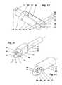
- FIG. 1is a perspective view of an embodiment of the present invention for gripping forceps shown in a closed view.
- FIG. 2is an opposite side perspective view of FIG. 1 with the forceps open.
- FIG. 3is a rear perspective view of the embodiment in FIG. 2 .
- FIG. 4is a top plan view of the embodiment in FIG. 1 in a closed position.
- FIG. 5is a side graphical view of half of a gripping forceps according to the present invention in a closed position noting motion lines.
- FIG. 6is a side graphical view of the embodiment in FIG. 5 but in an open position noting motion lines.
- FIG. 7is a side elevational view of the complete gripping forceps shown in a closed position.
- FIG. 8is the side elevational view in FIG. 7 in an open position.
- FIG. 9is a partial cutaway view of a gripping forceps with only one gripping jaw shown in a closed position.
- FIG. 10is a partial cutaway view of a gripping forceps as in FIG. 9 but with the jaw in a half open position.
- FIG. 11is a partial cutaway view of a gripping forceps as in FIG. 9 but with the jaw in a completely open position.
- FIG. 12is a perspective view of a main body element of the present invention.
- FIG. 13is a perspective view of a push element of the present invention.
- FIG. 14is a perspective view of a gripping jaw element of the present invention.
- the gripping forcepscomprise a main body 10 , a push element 40 , two gripping jaws 60 , 70 and a guide pin 30 .
- the main body 10(further noted in FIG. 12 ) includes a tube section 11 and a fork section 15 .
- the tube section 11has a boring 12 in which the push element 40 is guided.
- Two opposing adapter elements 14are molded at the back end of said push element. Via adapter elements 14 , the main body 10 is removably attached at a housing tube (not shown convenience), for example by means of a quarter-turn fastener mechanism.
- Fork section 15has two fork arms 16 , 26 that are arranged at the tube section 11 , as shown.
- the outer walls of the fork arms 16 , 26are parts of a cylinder jacket, for example.
- the diameter of said cylinderis the main body diameter 22 . In the embodiment, it is 4.8 mm.
- the interior walls of the fork arms 16 , 26are planes that are located as parallel opposites. The distance of the planes, for example, corresponds to the interior diameter of the boring 12 .
- Fork arms 16 , 26have a respective borings 28 , 28 .
- the borings 28 , 28which are in true alignment, have a designated midline 29 that perpendicularly intersects with the midline 13 of the main body 10 , as shown graphically.
- Each front fork arm 16(see FIG. 12 ) has above the boring 28 a recess 17 that is U-shaped, as a groove, for example.
- the base of the recesspartially has the surface area of a cylinder jacket.
- the center of the cylinder jacketis an upper pivot axis 61 .
- the rear fork arm 26has a comparable recess 27 .
- the latteris orientated downward here and in part encloses a lower pivot axis 71 .
- the pivot axes 61 , 71 and the midline 29 of the borings 28are located on one plane. This plane is aligned normally relative to the midline 13 of the main body 10 .
- Push element 40includes a push pin section 41 , a guide section 42 and a bearing section 45 .
- the push pin section 41which accommodates the push element 40 in the main body 10 , has a cylindrical form. At its free end, the push pin section has a tapped hole, if applicable. In the latter, the actuating rod guided in the housing tube of the forceps is then removably fastened. The tapped hole, the housing tube and the actuating rod are not shown in the figures.
- Push pin section 41is followed by the guide section 42 , as shown (see also FIG. 13 ).
- the latterhas at least approximately the form of a cuboid with two planar, parallel facing side surface areas 43 (as shown).
- these side surface areas 43bear against the interior walls of the fork arms 16 , 26 of the main body 10 , where they act as rotation prevention.
- the bent partial cylinder areas that border the side surface areas 43 at the top and bottomare part of a cylinder that has a diameter corresponding to the diameter of the main body.
- the bearing section 45corresponds to a thin-walled plate that has two link pins 48 , 49 and a guide groove 51 .
- the link pins 48 , 49have opposite parallel midlines 58 , 59 . Both midlines 58 , 59 clamp a plane that is normally positioned relative to the midline 52 of the push element 40 .
- the upper link pin 48according to (see FIG. 13 ) is orientated forwardly, whereas the lower pivot pin 49 is aligned backwardly. Both link pins 48 , 49 have the same distance relative to the midline 52 .
- the distance between the midlines 58 , 59is more than two-thirds of the main body diameter 22 .
- the link pins 48 , 49have a diameter of 1 mm, for example.
- a straight guide groove 51In the center between the link pins 48 , 49 is a straight guide groove 51 , which is open toward the free end of the bearing section 45 .
- the closed end of the guide groove 51has a part-cylindrical round corner.
- the midline of the round cornerperpendicularly intersects the midline 52 of the structural component 40 .
- gripping jaw 60is comprised of a jaw section 62 and a pivot area section 63 .
- Jaw section 62has the form of half of a longitudinally divided cylinder. The diameter of said cylinder corresponds to the main body diameter 22 .
- the front free end of the jaw section 62is rounded. The round corner radius corresponds to half of the main body diameter 22 .
- the at least approximately circular disk-shaped pivot area section 63runs in the front half of the gripping jaw 60 , i.e., the rear planar area of the pivot area section 63 —which contacts a bearing surface area 46 of the bearing section 45 of the push element 40 —is on a plane that is removed from the plane of the structural component center by half the width of the bearing section 45 .
- the structural component midline 68runs in said center plane. Also on the structural component midline 68 is the atraumatic jaw gripping surface area 83 , which is planar here (see FIG. 2 ).
- the pivot area section 63has a forward orientated pivot pin 65 .
- the pivot pin 65which has a midline 61 , has at least toward the bottom a cylindrical outer contour.
- the bending radius of the guide recess 67has a midpoint that is on the midline 61 of the pivot pin 65 . Consequently, the guide recess 67 has at least one edge 81 shaped like the arc of a circle, and the midpoint of said edge is also on the midline 61 .
- a pivot link recess 66is worked into the pivot area section 63 from the bottom.
- the pivot link recess 66is a straight groove, for example, and the width of said groove is slightly greater than the diameter of the link pins 48 , 49 of the push element 40 .
- parts of the base of the recesshave the surface area of a cylinder jacket.
- auxiliary line 69has been drawn on the visible planar surface area that bears against the interior wall of the appropriate fork arm 16 , 26 of the main body 10 when the gripping forceps are assembled.
- Auxiliary line 69is furthermore perpendicular on the plane of the jaw gripping surface area 83 .
- the front jacket line of the pivot pin 65 and the edge of the rear, planar wall of the pivot link recess 66are on said auxiliary line 69 .
- the fifth and last structural component of the gripping forcepsis the cylindrical guide pin 30 , see for example FIG. 2 .
- pin 30has a diameter of approximately 1 mm, and its length is slightly less than the main body diameter 22 . Pin 30 sits in the borings 28 of the gripping arms 16 , 26 , for example by means of a cross press fit.
- all five parts 10 , 30 , 40 , 60 , 70 of the gripping forcepsare respectively made of a rust- and acid resistant steel, such as the chromium steel X20Cr13, for example.
- FIGS. 5 and 6which pictorially first show the operating principle for only one gripping jaw 60 .
- gripping jaw 60is a jaw section 62 , 72 to which a lever arm 64 , 74 with a recess 66 , 76 and a pivot pin 65 , 75 is fastened.
- the main body 10is a boring 12 with a recess 17 arranged thereon.
- the push element 40is disposed in the boring 12 . It engages with the pivot link recess 66 , 76 via a link pin 48 .
- the push element 40is moved toward the left (as shown) in the boring 12 .
- the link pin 48urgingly acts on the pivot link recess 66 that, together with the lever arm 64 and the jaw section 62 , pivots upward in clockwise fashion. While doing so, the pivot pin 65 rotates in the recess 17 of the main body 10 (see for FIG. 6 ).
- FIGS. 7 and 8depict the principle for the entire gripping forceps as noted herein.
- the outlines shown in FIGS. 5 and 6are first reflected downward. Then the original and the mirror image are slid into one another until the gripping jaws 60 , 70 are located together, according to FIG. 4 .
- both link pins 48 , 49are firmly arranged on a joint push element 40 .
- the individual parts 10 , 30 , 40 , 60 , 70 of the actual gripping forcepsare assembled in that the push element 40 , with its guide section 42 first, is slid almost completely into the boring 12 of the main body 10 .
- the insertion depthis shown in. FIG. 9 .
- the upper gripping jaw 60is inserted from the top into the gap between the front fork arm 16 and the bearing surface area 46 of the push element 50 .
- the gripping jaw 60is in extended position, i.e., its midline 68 runs parallel to the midline 13 of the main body 10 during 5 the insertion process.
- pivot pin 65 of the gripping jaw 60comes to bear in the recess 17 of the main body 10 .
- Pivot axis 61is spaced a distance 21 from the midline 29 of boring 28 and pivot axis 71 is spaced by the same distance 21 from the midline 29 of the boring 28 , thereby facilitating movement of the law section along directional arrows 2 . 2 .
- the pivot link recess 66 of the gripping jaw 60is slid over the link pin 49 of the push element 40 .
- the insertion of the gripping jaw 60is completed as soon as the midline 68 of the gripping jaw 60 corresponds to the midline 13 of the twain body 10 .
- the lower gripping jaw 70is inserted in the same manner from below.
- five recesses and/or boringsare, at least partially, positioned on top of each other in the pivot area of the gripping forceps. Viewed from outward to inward, these are the two borings 28 of the fork arms 16 , 26 , the two sickle shaped guide recesses 67 , 77 of the gripping jaws 60 , 70 and the guide groove 51 of the push element 40 . Finally, the guide pin 30 is then inserted through all recesses and affixed; see again FIGS. 1 to 4 .
- FIG. 9 to 11The function of the sickle shaped guide recess 67 of the gripping jaw 60 , which has not been described so far, is shown now in FIG. 9 to 11 . As noted therein, the gripping forceps are shown in longitudinal section without the lower gripping jaw 70 . Also, a piece is broken out of the push element 40
- the main body 10accommodates the gripping jaw 60 in the recess 17 and on the guide pin 30 .
- the recess 17which is open on one side, accommodates the pivot pin 65 .
- the guide-pivot link recess 66bears against the guide pin 30 at least via the edge 81 . Because the guide recess 67 bears against the guide pin 30 , it is possible to situate the pivot axis 61 of the gripping jaw 30 far away from the midline 13 within the main body 10 . This allows a large gripping forceps lever arm.
Landscapes
- Health & Medical Sciences (AREA)
- Surgery (AREA)
- Life Sciences & Earth Sciences (AREA)
- Biomedical Technology (AREA)
- Nuclear Medicine, Radiotherapy & Molecular Imaging (AREA)
- Engineering & Computer Science (AREA)
- Ophthalmology & Optometry (AREA)
- Heart & Thoracic Surgery (AREA)
- Medical Informatics (AREA)
- Molecular Biology (AREA)
- Animal Behavior & Ethology (AREA)
- General Health & Medical Sciences (AREA)
- Public Health (AREA)
- Veterinary Medicine (AREA)
- Surgical Instruments (AREA)
Abstract
Description
Claims (6)
Applications Claiming Priority (4)
| Application Number | Priority Date | Filing Date | Title |
|---|---|---|---|
| DE102006028001.6 | 2006-06-14 | ||
| DE102006028001ADE102006028001B4 (en) | 2006-06-14 | 2006-06-14 | Surgical grasping forceps |
| DE102006028001 | 2006-06-14 | ||
| PCT/EP2007/005245WO2007144172A1 (en) | 2006-06-14 | 2007-06-14 | Surgical gripping forceps |
Publications (2)
| Publication Number | Publication Date |
|---|---|
| US20090259248A1 US20090259248A1 (en) | 2009-10-15 |
| US9844388B2true US9844388B2 (en) | 2017-12-19 |
Family
ID=38512236
Family Applications (1)
| Application Number | Title | Priority Date | Filing Date |
|---|---|---|---|
| US12/304,365Active2030-08-30US9844388B2 (en) | 2006-06-14 | 2007-06-14 | Surgical gripping forceps |
Country Status (4)
| Country | Link |
|---|---|
| US (1) | US9844388B2 (en) |
| EP (1) | EP2026705B1 (en) |
| DE (1) | DE102006028001B4 (en) |
| WO (1) | WO2007144172A1 (en) |
Cited By (3)
| Publication number | Priority date | Publication date | Assignee | Title |
|---|---|---|---|---|
| USD888950S1 (en)* | 2018-10-10 | 2020-06-30 | Bolder Surgical, Llc | Yoke assembly for a surgical instrument |
| US20210282796A1 (en)* | 2018-11-30 | 2021-09-16 | Olympus Corporation | Gripping mechanism |
| US20220192691A1 (en)* | 2019-04-02 | 2022-06-23 | Servocad Microtronics, S.L. | Laparoscopic surgical instrument |
Families Citing this family (17)
| Publication number | Priority date | Publication date | Assignee | Title |
|---|---|---|---|---|
| DE102006040529A1 (en)* | 2006-08-30 | 2008-03-13 | Paul Peschke Gmbh | Surgical grasping forceps |
| US9456839B2 (en) | 2010-06-18 | 2016-10-04 | Intuitive Surgical Operations, Inc. | Scissor bias for direct pull surgical instrument |
| ES2653806T3 (en) | 2011-01-21 | 2018-02-08 | Obalon Therapeutics, Inc. | Intragastric device |
| US8529580B1 (en) | 2012-11-01 | 2013-09-10 | Hasan M. Sh. Sh. Alshemari | Surgical grasping instrument with U-shaped jaws in combination with a tympanostomy tube |
| US9498281B2 (en)* | 2012-11-27 | 2016-11-22 | Covidien Lp | Surgical apparatus |
| CN103845112B (en)* | 2012-12-05 | 2018-03-27 | 展爱杰 | Laparoscope Minimally Invasive Surgery performs apparatus with multiple degrees of freedom |
| DE102013101651A1 (en) | 2013-02-20 | 2014-09-04 | Karl Storz Gmbh & Co. Kg | Endoscopic instrument and shaft for an endoscopic instrument |
| DE102014109663A1 (en) | 2014-07-10 | 2016-01-14 | Karl Storz Gmbh & Co. Kg | Endoscopic instrument |
| US12433574B2 (en) | 2015-09-15 | 2025-10-07 | Cook Medical Technologies Llc | Locking forceps |
| WO2017048594A1 (en) | 2015-09-15 | 2017-03-23 | Cook Medical Technologies Llc | Forceps with locking mechanism |
| USD796041S1 (en)* | 2016-02-03 | 2017-08-29 | Karl Storz Gmbh & Co. Kg | Optical forceps |
| USD796040S1 (en)* | 2016-02-03 | 2017-08-29 | Karl Storz Gmbh & Co. Kg | Optical forceps |
| CN107157548A (en)* | 2017-05-03 | 2017-09-15 | 杭州康友医疗设备有限公司 | A kind of two-piece type operating forceps |
| EP3578125B1 (en)* | 2018-06-08 | 2024-05-08 | Erbe Elektromedizin GmbH | Laparoscopic forceps instrument |
| DE102021132425B3 (en) | 2021-12-09 | 2023-05-04 | Karl Storz Se & Co. Kg | Handling device for an electrosurgical instrument, method for producing a handling device and electrosurgical instrument |
| DE102021132427A1 (en) | 2021-12-09 | 2023-06-15 | Karl Storz Se & Co. Kg | Deflection mechanism for an endoscopic instrument, endoscopic instrument and surgical system |
| JP2024084541A (en)* | 2022-12-13 | 2024-06-25 | 日本発條株式会社 | Jaw assembly and surgical instrument using same |
Citations (32)
| Publication number | Priority date | Publication date | Assignee | Title |
|---|---|---|---|---|
| US3895636A (en)* | 1973-09-24 | 1975-07-22 | William Schmidt | Flexible forceps |
| US4038987A (en)* | 1974-02-08 | 1977-08-02 | Olympus Optical Co., Ltd. | Forceps device for endoscope |
| US4887612A (en)* | 1988-04-27 | 1989-12-19 | Esco Precision, Inc. | Endoscopic biopsy forceps |
| US5275615A (en) | 1992-09-11 | 1994-01-04 | Anthony Rose | Medical instrument having gripping jaws |
| US5290309A (en) | 1991-04-19 | 1994-03-01 | Lutz Kothe | Surgical instrument |
| US5342390A (en) | 1990-05-10 | 1994-08-30 | Symbiosis Corporation | Thumb-activated actuating member for imparting reciprocal motion to a push rod of a disposable laparoscopic surgical instrument |
| EP0623316A1 (en) | 1993-05-04 | 1994-11-09 | Gyrus Medical Limited | Laparoscopic surgical instrument |
| US5373854A (en) | 1993-07-15 | 1994-12-20 | Kolozsi; William Z. | Biopsy apparatus for use in endoscopy |
| US5569299A (en) | 1995-03-01 | 1996-10-29 | Symbiosis Corporation | Endoscopic urological biopsy forceps |
| US5700275A (en)* | 1996-04-25 | 1997-12-23 | United States Surgical Corporation | Articulating endoscopic surgical instrument |
| US5749893A (en) | 1993-04-30 | 1998-05-12 | United States Surgical Corporation | Surgical instrument having an articulated jaw structure and a detachable knife |
| US5762613A (en)* | 1996-05-07 | 1998-06-09 | Spectrascience, Inc. | Optical biopsy forceps |
| US5779648A (en)* | 1994-02-08 | 1998-07-14 | Boston Scientific Corporation | Multi-motion cutter multiple biopsy sampling device |
| US5843000A (en)* | 1996-05-07 | 1998-12-01 | The General Hospital Corporation | Optical biopsy forceps and method of diagnosing tissue |
| US5964779A (en)* | 1997-07-02 | 1999-10-12 | Aesculap Ag & Co. Kg | Surgical tubular-shafted instrument |
| US6019780A (en)* | 1996-12-17 | 2000-02-01 | Tnco, Inc. | Dual pin and groove pivot for micro-instrument |
| US6083150A (en)* | 1999-03-12 | 2000-07-04 | C. R. Bard, Inc. | Endoscopic multiple sample biopsy forceps |
| US6086606A (en)* | 1998-05-06 | 2000-07-11 | Knodel; Bryan D. | Manually-operable surgical tool suitable for laparoscopic operations, readily adaptable for different functions by quick change of tissue-contacting operational elements |
| US6159162A (en)* | 1998-05-04 | 2000-12-12 | Lsvp International, Inc. | Biopsy apparatus |
| DE20120249U1 (en) | 2001-12-11 | 2002-03-07 | Aesculap AG & Co. KG, 78532 Tuttlingen | Surgical instrument |
| US6394998B1 (en)* | 1999-01-22 | 2002-05-28 | Intuitive Surgical, Inc. | Surgical tools for use in minimally invasive telesurgical applications |
| US6451018B1 (en)* | 1997-11-14 | 2002-09-17 | Sherwood Services Ag | Laparoscopic bipolar electrosurgical instrument |
| US20020143358A1 (en)* | 2001-02-13 | 2002-10-03 | Domingo Nicanor A. | Method and apparatus for micro-dissection of vascular occlusions |
| US20030135204A1 (en)* | 2001-02-15 | 2003-07-17 | Endo Via Medical, Inc. | Robotically controlled medical instrument with a flexible section |
| US20040044363A1 (en)* | 2002-08-27 | 2004-03-04 | Fowler David N. | Apparatus and method for removing a clip |
| US6767349B2 (en)* | 2001-03-01 | 2004-07-27 | Pentax Corporation | Bipolar forceps for endoscopes |
| US6818007B1 (en)* | 1999-09-16 | 2004-11-16 | Syclix Limited | Tool and an effector |
| US20050021002A1 (en)* | 2003-06-10 | 2005-01-27 | Deckman Robert K. | Catheter systems and methods for crossing vascular occlusions |
| US20050043758A1 (en)* | 2003-08-18 | 2005-02-24 | Scimed Life Systems, Inc. | Endoscopic medical instrument and related methods of use |
| US6964662B2 (en)* | 2002-04-09 | 2005-11-15 | Pentax Corporation | Endoscopic forceps instrument |
| US6969389B2 (en)* | 2002-04-09 | 2005-11-29 | Pentax Corporation | Bipolar hemostatic forceps for an endoscope |
| US7762960B2 (en)* | 2005-05-13 | 2010-07-27 | Boston Scientific Scimed, Inc. | Biopsy forceps assemblies |
Family Cites Families (1)
| Publication number | Priority date | Publication date | Assignee | Title |
|---|---|---|---|---|
| US6585735B1 (en)* | 1998-10-23 | 2003-07-01 | Sherwood Services Ag | Endoscopic bipolar electrosurgical forceps |
- 2006
- 2006-06-14DEDE102006028001Apatent/DE102006028001B4/enactiveActive
- 2007
- 2007-06-14WOPCT/EP2007/005245patent/WO2007144172A1/enactiveApplication Filing
- 2007-06-14USUS12/304,365patent/US9844388B2/enactiveActive
- 2007-06-14EPEP07726009Apatent/EP2026705B1/enactiveActive
Patent Citations (34)
| Publication number | Priority date | Publication date | Assignee | Title |
|---|---|---|---|---|
| US3895636A (en)* | 1973-09-24 | 1975-07-22 | William Schmidt | Flexible forceps |
| US4038987A (en)* | 1974-02-08 | 1977-08-02 | Olympus Optical Co., Ltd. | Forceps device for endoscope |
| US4887612A (en)* | 1988-04-27 | 1989-12-19 | Esco Precision, Inc. | Endoscopic biopsy forceps |
| US5342390A (en) | 1990-05-10 | 1994-08-30 | Symbiosis Corporation | Thumb-activated actuating member for imparting reciprocal motion to a push rod of a disposable laparoscopic surgical instrument |
| US5290309A (en) | 1991-04-19 | 1994-03-01 | Lutz Kothe | Surgical instrument |
| US5275615A (en) | 1992-09-11 | 1994-01-04 | Anthony Rose | Medical instrument having gripping jaws |
| US5749893A (en) | 1993-04-30 | 1998-05-12 | United States Surgical Corporation | Surgical instrument having an articulated jaw structure and a detachable knife |
| EP0623316A1 (en) | 1993-05-04 | 1994-11-09 | Gyrus Medical Limited | Laparoscopic surgical instrument |
| US5373854A (en) | 1993-07-15 | 1994-12-20 | Kolozsi; William Z. | Biopsy apparatus for use in endoscopy |
| US5779648A (en)* | 1994-02-08 | 1998-07-14 | Boston Scientific Corporation | Multi-motion cutter multiple biopsy sampling device |
| US5569299A (en) | 1995-03-01 | 1996-10-29 | Symbiosis Corporation | Endoscopic urological biopsy forceps |
| US5700275A (en)* | 1996-04-25 | 1997-12-23 | United States Surgical Corporation | Articulating endoscopic surgical instrument |
| US5843000A (en)* | 1996-05-07 | 1998-12-01 | The General Hospital Corporation | Optical biopsy forceps and method of diagnosing tissue |
| US5762613A (en)* | 1996-05-07 | 1998-06-09 | Spectrascience, Inc. | Optical biopsy forceps |
| US6129683A (en)* | 1996-05-07 | 2000-10-10 | Spectrascience, Inc. | Optical biopsy forceps |
| US6019780A (en)* | 1996-12-17 | 2000-02-01 | Tnco, Inc. | Dual pin and groove pivot for micro-instrument |
| US5964779A (en)* | 1997-07-02 | 1999-10-12 | Aesculap Ag & Co. Kg | Surgical tubular-shafted instrument |
| US6451018B1 (en)* | 1997-11-14 | 2002-09-17 | Sherwood Services Ag | Laparoscopic bipolar electrosurgical instrument |
| US6159162A (en)* | 1998-05-04 | 2000-12-12 | Lsvp International, Inc. | Biopsy apparatus |
| US6086606A (en)* | 1998-05-06 | 2000-07-11 | Knodel; Bryan D. | Manually-operable surgical tool suitable for laparoscopic operations, readily adaptable for different functions by quick change of tissue-contacting operational elements |
| US6394998B1 (en)* | 1999-01-22 | 2002-05-28 | Intuitive Surgical, Inc. | Surgical tools for use in minimally invasive telesurgical applications |
| US6083150A (en)* | 1999-03-12 | 2000-07-04 | C. R. Bard, Inc. | Endoscopic multiple sample biopsy forceps |
| US6818007B1 (en)* | 1999-09-16 | 2004-11-16 | Syclix Limited | Tool and an effector |
| US20020143358A1 (en)* | 2001-02-13 | 2002-10-03 | Domingo Nicanor A. | Method and apparatus for micro-dissection of vascular occlusions |
| US20030135204A1 (en)* | 2001-02-15 | 2003-07-17 | Endo Via Medical, Inc. | Robotically controlled medical instrument with a flexible section |
| US6767349B2 (en)* | 2001-03-01 | 2004-07-27 | Pentax Corporation | Bipolar forceps for endoscopes |
| DE20120249U1 (en) | 2001-12-11 | 2002-03-07 | Aesculap AG & Co. KG, 78532 Tuttlingen | Surgical instrument |
| US6964662B2 (en)* | 2002-04-09 | 2005-11-15 | Pentax Corporation | Endoscopic forceps instrument |
| US6969389B2 (en)* | 2002-04-09 | 2005-11-29 | Pentax Corporation | Bipolar hemostatic forceps for an endoscope |
| US20040044363A1 (en)* | 2002-08-27 | 2004-03-04 | Fowler David N. | Apparatus and method for removing a clip |
| US20050021002A1 (en)* | 2003-06-10 | 2005-01-27 | Deckman Robert K. | Catheter systems and methods for crossing vascular occlusions |
| US20050043758A1 (en)* | 2003-08-18 | 2005-02-24 | Scimed Life Systems, Inc. | Endoscopic medical instrument and related methods of use |
| US7951165B2 (en)* | 2003-08-18 | 2011-05-31 | Boston Scientific Scimed, Inc. | Endoscopic medical instrument and related methods of use |
| US7762960B2 (en)* | 2005-05-13 | 2010-07-27 | Boston Scientific Scimed, Inc. | Biopsy forceps assemblies |
Non-Patent Citations (4)
| Title |
|---|
| German Application Serial No. 07 726 009.9 dated Feb. 23, 2011 Office Action, 6 pages. (English translation). |
| Getman U.S. Appl. No. DE 10 2006 028 001 filed Jun. 14, 2006, Office Action, 5 pages (full translation). |
| International Publication No. WO 02/064020 published Aug. 22, 2002 (6 pages). |
| International Search Report and Written Opinion, 6 pages, PCT No. PCT/EP2007/005245, dated Sep. 25, 2007. |
Cited By (5)
| Publication number | Priority date | Publication date | Assignee | Title |
|---|---|---|---|---|
| USD888950S1 (en)* | 2018-10-10 | 2020-06-30 | Bolder Surgical, Llc | Yoke assembly for a surgical instrument |
| US20210282796A1 (en)* | 2018-11-30 | 2021-09-16 | Olympus Corporation | Gripping mechanism |
| US12029444B2 (en)* | 2018-11-30 | 2024-07-09 | Olympus Corporation | Gripping mechanism |
| US20220192691A1 (en)* | 2019-04-02 | 2022-06-23 | Servocad Microtronics, S.L. | Laparoscopic surgical instrument |
| US12193695B2 (en)* | 2019-04-02 | 2025-01-14 | Servocad Microtronics, S.L. | Laparoscopic surgical instrument |
Also Published As
| Publication number | Publication date |
|---|---|
| EP2026705A1 (en) | 2009-02-25 |
| WO2007144172A1 (en) | 2007-12-21 |
| DE102006028001B4 (en) | 2009-11-26 |
| DE102006028001A1 (en) | 2007-12-20 |
| US20090259248A1 (en) | 2009-10-15 |
| EP2026705B1 (en) | 2013-02-20 |
Similar Documents
| Publication | Publication Date | Title |
|---|---|---|
| US9844388B2 (en) | Surgical gripping forceps | |
| US9700335B2 (en) | Surgical gripping forceps | |
| US8123780B2 (en) | Dismantable medical forceps system | |
| US5709706A (en) | Surgical instrument | |
| US5269804A (en) | Endoscopic colo-rectal bowel clamp | |
| US7476237B2 (en) | Surgical instrument | |
| TWI695701B (en) | End effector and end effector drive apparatus | |
| US6077290A (en) | Endoscopic instrument with removable front end | |
| US6705989B2 (en) | Retractor for use in endoscopic surgery and medical instrument for introducing a retractor and method for the use of a retractor in endoscopic surgery | |
| US7621927B2 (en) | Medical instrument with a mechanical coupling | |
| US5336238A (en) | Surgical instrument capable of disassembly | |
| US8409229B2 (en) | Surgical instrument | |
| CA2482198A1 (en) | Surgical device with malleable shaft | |
| WO1998026723A1 (en) | Dual pin and groove pivot for micro-instrument | |
| JP2012527328A (en) | Endoscopic instrument | |
| US9005239B2 (en) | Medical instrument | |
| ES2234950T3 (en) | SURGICAL INSTRUMENT. | |
| EP0066465A2 (en) | Biopsic forceps | |
| JP6449884B2 (en) | Surgical instrument for manipulating, positioning and securing a surgical rod relative to an implant | |
| US9101367B2 (en) | Medical instrument for dissecting tissue | |
| CN113710172A (en) | Laparoscopic surgical instrument | |
| US20230014925A1 (en) | Surgical tool | |
| US20060047304A1 (en) | Medical forceps | |
| CN216569870U (en) | Bendable multi-link device | |
| DE102004009199A1 (en) | Surgical shaft instruments for open surgery |
Legal Events
| Date | Code | Title | Description |
|---|---|---|---|
| AS | Assignment | Owner name:PAUL PESCHKE GMBH, GERMANY Free format text:ASSIGNMENT OF ASSIGNORS INTEREST;ASSIGNORS:GANTER, HANS;REINAUER, JOSEF;REEL/FRAME:022337/0832;SIGNING DATES FROM 20090130 TO 20090202 Owner name:PAUL PESCHKE GMBH, GERMANY Free format text:ASSIGNMENT OF ASSIGNORS INTEREST;ASSIGNORS:GANTER, HANS;REINAUER, JOSEF;SIGNING DATES FROM 20090130 TO 20090202;REEL/FRAME:022337/0832 | |
| AS | Assignment | Owner name:KARL STORZ GMBH & CO. KG, GERMANY Free format text:ASSIGNMENT OF ASSIGNORS INTEREST;ASSIGNOR:PAUL PESCHKE GMBH;REEL/FRAME:027671/0376 Effective date:20090130 | |
| STCF | Information on status: patent grant | Free format text:PATENTED CASE | |
| AS | Assignment | Owner name:KARL STORZ SE & CO. KG, GERMANY Free format text:CHANGE OF NAME;ASSIGNOR:KARL STORZ GMBH & CO. KG;REEL/FRAME:045373/0627 Effective date:20170911 | |
| FEPP | Fee payment procedure | Free format text:ENTITY STATUS SET TO UNDISCOUNTED (ORIGINAL EVENT CODE: BIG.); ENTITY STATUS OF PATENT OWNER: LARGE ENTITY | |
| MAFP | Maintenance fee payment | Free format text:PAYMENT OF MAINTENANCE FEE, 4TH YEAR, LARGE ENTITY (ORIGINAL EVENT CODE: M1551); ENTITY STATUS OF PATENT OWNER: LARGE ENTITY Year of fee payment:4 | |
| MAFP | Maintenance fee payment | Free format text:PAYMENT OF MAINTENANCE FEE, 8TH YEAR, LARGE ENTITY (ORIGINAL EVENT CODE: M1552); ENTITY STATUS OF PATENT OWNER: LARGE ENTITY Year of fee payment:8 |