US9841855B2 - Systems and methods for capacitive touch detection - Google Patents
Systems and methods for capacitive touch detectionDownload PDFInfo
- Publication number
- US9841855B2 US9841855B2US14/695,386US201514695386AUS9841855B2US 9841855 B2US9841855 B2US 9841855B2US 201514695386 AUS201514695386 AUS 201514695386AUS 9841855 B2US9841855 B2US 9841855B2
- Authority
- US
- United States
- Prior art keywords
- comparison result
- generate
- touch
- signal
- internal
- Prior art date
- Legal status (The legal status is an assumption and is not a legal conclusion. Google has not performed a legal analysis and makes no representation as to the accuracy of the status listed.)
- Expired - Fee Related, expires
Links
Images


Classifications
- G—PHYSICS
- G06—COMPUTING OR CALCULATING; COUNTING
- G06F—ELECTRIC DIGITAL DATA PROCESSING
- G06F3/00—Input arrangements for transferring data to be processed into a form capable of being handled by the computer; Output arrangements for transferring data from processing unit to output unit, e.g. interface arrangements
- G06F3/01—Input arrangements or combined input and output arrangements for interaction between user and computer
- G06F3/03—Arrangements for converting the position or the displacement of a member into a coded form
- G06F3/041—Digitisers, e.g. for touch screens or touch pads, characterised by the transducing means
- G06F3/044—Digitisers, e.g. for touch screens or touch pads, characterised by the transducing means by capacitive means
- G06F3/0446—Digitisers, e.g. for touch screens or touch pads, characterised by the transducing means by capacitive means using a grid-like structure of electrodes in at least two directions, e.g. using row and column electrodes
- G—PHYSICS
- G06—COMPUTING OR CALCULATING; COUNTING
- G06F—ELECTRIC DIGITAL DATA PROCESSING
- G06F3/00—Input arrangements for transferring data to be processed into a form capable of being handled by the computer; Output arrangements for transferring data from processing unit to output unit, e.g. interface arrangements
- G06F3/01—Input arrangements or combined input and output arrangements for interaction between user and computer
- G06F3/03—Arrangements for converting the position or the displacement of a member into a coded form
- G06F3/041—Digitisers, e.g. for touch screens or touch pads, characterised by the transducing means
- G06F3/044—Digitisers, e.g. for touch screens or touch pads, characterised by the transducing means by capacitive means
- G—PHYSICS
- G06—COMPUTING OR CALCULATING; COUNTING
- G06F—ELECTRIC DIGITAL DATA PROCESSING
- G06F3/00—Input arrangements for transferring data to be processed into a form capable of being handled by the computer; Output arrangements for transferring data from processing unit to output unit, e.g. interface arrangements
- G06F3/01—Input arrangements or combined input and output arrangements for interaction between user and computer
- G06F3/03—Arrangements for converting the position or the displacement of a member into a coded form
- G06F3/041—Digitisers, e.g. for touch screens or touch pads, characterised by the transducing means
- G06F3/0416—Control or interface arrangements specially adapted for digitisers
- G06F3/04166—Details of scanning methods, e.g. sampling time, grouping of sub areas or time sharing with display driving
Definitions
- the technology described in this patent documentrelates generally to electronic circuits and more particularly to touch detection circuits.
- Touch screensare widely used in various applications, such as automated teller machines, mobile phones, laptops, desktops, etc.
- a touch screenis used for detecting different types of user inputs. Compared to external input devices e.g., a keyboard, a mouse), a touch screen is often considered as a more effective interface in terms of convenience, flexibility and cost.
- a touch event on a touch screenmay be sensed through various methods, such as, capacitance sensing methods. For example, a user touches a point on a touch button (or a touch pad, a touch screen). The presence or movement of a user's finger in the vicinity of the touch button disturbs or changes the electric field associated with the capacitance of the touch button and thus modifies the capacitance of the touch button. Therefore, the touch event may be detected according to the capacitance change.
- the systemincludes: a sensing capacitive network configured to generate a touch-sensing signal based at least in part on a touch panel capacitance; an internal capacitive network configured to generate an input signal based at least in part on a predetermined internal capacitance; a comparative network configured to compare the touch-sensing signal with a reference signal to generate a first comparison result and compare the input signal with the reference signal to generate a second comparison result; and a signal processing component configured to generate a detection result to indicate whether a touch event occurs on the touch panel based at least in part on the first comparison result and the second comparison result.
- a methodfor touch detection.
- a touch-sensing signalis generated based at least in part on a touch panel capacitance.
- An input signalis generated based at least in part on a predetermined internal capacitance.
- the touch-sensing signalis compared with a reference signal to generate a first comparison result.
- the input signalis compared with the reference signal to generate a second comparison result.
- a detection resultis generated to indicate whether a touch event occurs on the touch panel based at least in part on the first comparison result and the second comparison result.
- a system for touch detectionincludes: a touch panel associated with a touch panel capacitance; an internal capacitive network configured to generate an input signal based at least in part on a predetermined internal capacitance; a comparative network configured to compare a touch-sensing signal with a reference signal to generate a first comparison result and compare the input signal with the reference signal to generate a second comparison result, the touch-sensing signal being associated with the touch panel capacitance; and a signal processing component configured to generate a detection result to indicate whether a touch event occurs on the touch panel based at least in part on the first comparison result and the second comparison result.
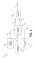
- FIG. 1depicts an example diagram showing a system for touch detection.
- FIG. 2depicts an example diagram of the touch detection nit as shown in FIG. 1 .
- FIG. 3depicts another example diagram of the touch detection unit as shown in FIG. 1 .
- FIG. 4depicts an example timing diagram of the touch detection unit as shown in FIG. 3 .
- FIG. 5depicts an example flow chart for touch detection.
- a reference voltageis often needed for capacitance measurements in some conventional capacitance sensing methods, such as capacitance-sensing successive approximation (CSA) measurements and capacitance sensing sigma delta (CSD) measurements.
- CSAcapacitance-sensing successive approximation
- CSDcapacitance sensing sigma delta
- the reference voltagemay be affected by noises in supply voltages, etc. The variation of the reference voltage may cause inaccurate capacitance measurements and thus inaccurate detection results.
- a reference generator with enhanced power supply rejection (PSR)may be employed to generate a stable reference signal under noisy supply voltages. Such an enhanced reference generator, however, usually occupies a larger chip area, which may not be desirable in some circumstances.
- FIG. 1depicts an example diagram showing a system for touch detection.
- a driving unit 104applies a scan signal 112 to a touch panel 102 which includes a matrix of conductive lines 108 and conductive columns 110 overlaid on the display area of the touch panel 102 . Capacitance measurements are performed on the touch panel 102 .
- a touch detection unit 106generates a touch detection result 116 in response to an input signal 114 from the touch panel 102 .
- the touch detection result 116indicates whether a touch event occurs on the touch panel 102 .
- the driving unit 104applies the scan signal 112 to the conductive lines 108 and/or the conductive columns 110 . If a sensing capacitance associated with a conductive line or a conductive column changes, the input signal 114 which includes raw capacitance measurement data changes correspondingly.
- the touch detection unit 106determines whether a touch event occurs by comparing the input signal 114 with a baseline signal. For example, the conductive lines 108 and the conductive columns 110 may be patterned in respectively different layers and do not contact each other.
- FIG. 2depicts an example diagram of the touch detection unit as shown in FIG. 1 .
- a sensing capacitive network 202generates a touch-sensing signal 210 which indicates a capacitance of the touch panel 102 .
- An internal capacitive network 204generates an input signal 214 associated with a predetermined internal capacitance.
- a comparative network 206compares a reference signal 212 with the touch-sensing signal 210 to generate a comparison result 216 and compares the reference signal 212 with the input signal 214 to generate another comparison result 218 .
- the signal processing component 208determines the detection result 116 using the comparison results 216 and 218 .
- the sensing capacitive network 202includes one or more sensing capacitors associated with the capacitance of the touch panel 102 which changes in response to a touch event (e.g., a user's finger touching on the touch panel 102 ).
- the internal capacitive network 204includes one or more internal capacitors associated with the predetermined internal capacitance.
- the comparative network 206includes one or more first comparators to compare the touch-sensing signal 210 and the reference signal 212 , and one or more second comparators to compare the input signal 214 and the reference signal 212 .
- a reference signal generator 222generates the reference signal 212 . In certain embodiments, the reference signal generator 222 is not included in the touch detection unit 106 .
- FIG. 3depicts another example diagram of the touch detection unit as shown in FIG. 1 .
- a sensing capacitor 302is charged by a current I 1 from a current source component 306 when the switch 314 is closed (e.g., being turned on).
- a comparator 310 within the comparative network 206compares the touch-sensing signal 210 generated by the sensing capacitor 302 with the reference signal 212 to generate a first comparison result 332 .
- an internal capacitor 304is charged by a current I 0 from a current source component 308 when the switch 316 is closed (e.g., being turned on).
- Another comparator 312 within the comparative network 206compares the input signal 214 generated by the internal capacitor 304 with the reference signal 212 to generate a second comparison result 330 .
- the detection result 116is generated based on the first comparison result 332 and the second comparison result 330 .
- a flip-flop 322outputs a signal 328 (i.e., CAP_TIME) at a Clk terminal in response to the first comparison result 332 .
- Another flip-flop 324outputs a signal 330 (i.e., CLK) at a Clk terminal in response to the second comparison result 330 .
- a counter component 326determines a frequency difference between the signal 328 (i.e., CAP_TIME) and the signal 330 (i.e., CLK) and generates the detection result 116 .
- a NOT gate 336generates a control signal 350 using the first comparison result 332 to close or open the switch 314 .
- the comparator 310generates the first comparison result 332 at a logic high level.
- the NOT gate 336generates the control signal 350 at a logic low level to open (e.g., to turn off) the switch 314 and the charging of the sensing capacitor 302 stops.
- a switch 354is closed (e.g., being turned on) in response to the first comparison result 332 so that the sensing capacitor 302 is discharged.
- another NOT gate 338generates a control signal 352 to close or open the switch 316 .
- the comparator 312when the input signal 214 becomes larger in magnitude than the reference signal 212 , the comparator 312 generates the second comparison result 334 at the logic high level.
- the NOT gate 338generates the control signal 352 at the logic low level to open (e.g., to turn off) the switch 316 and the charging of the internal capacitor 304 stops.
- a switch 356is closed (e.g., being turned on) in response to the second comparison result 334 so that the internal capacitor 304 is discharged.
- the sensing capacitor 302represents a self capacitance associated with one or more conductive lines or conductive columns of the touch panel 102 . In certain embodiments, the sensing capacitor 302 represents a mutual capacitance between a conductive line and a conductive column of the touch panel 102 .
- the capacitance of the internal capacitor 304is 2 pF, which is approximately one tenth of the capacitance of the sensing capacitor 302 when no touch event occurs.
- the frequency of the signal 328i.e., CAP_TIME
- that of the signal 330i.e., CLK
- the capacitance of the sensing capacitor 302changes.
- the cycle time of the signal 328i.e., CAP_TIME
- changese.g., linearly
- the cycle time of the signal 330i.e., CLK
- C senserepresents the capacitance of the sensing capacitor 302
- C internalrepresents the capacitance of the internal capacitor 304
- V refrepresents the reference signal 212 .
- FIG. 4depicts an example timing diagram of the touch detection unit as shown in FIG. 3 .
- the counter component 326determines a number of cycles of the signal 330 (e.g., as shown by a waveform 402 ) during a predetermined time period t.
- the signal 330i.e., CLK
- the counter component 326determines a number of cycles of the signal 328 (e.g., as shown by a waveform 404 ) during the predetermined time period t.
- the number of cycles of the signal 328i.e., CAP_TIME
- the number of cycles of the signal 328is determined as follows:
- Nthe number of cycles of the signal 330 in the time period t.
- the comparison between the number of cycles of the signal 330 and the number of cycles of the signal 328 in the time period tis carried out for determining the detection result 116 .
- the same reference signal 212is used for comparison with the outputs of the sensing capacitive network 202 and the internal capacitive network 204 respectively, and thus the detection result 116 is not affected by process variants, noises in supply voltages, temperature changes, etc.
- the reference signal 212varies in response to noisy supply voltages
- both the signal 328 (i.e., CAP_TIME) and the signal 330 (i.e., CLK)would be affected (e.g., synchronously), and the detection result 116 may not be affected.
- the current I 0 and the currentmay be affected.
- the reference signal generator 222does not need to have a high PSR, and thus it may be designed properly to save chip area.
- FIG. 5depicts an example flow chart for touch detection.
- a touch-sensing signalis generated based at least in part on a touch panel capacitance.
- an input signalis generated based at least in part on a predetermined internal capacitance.
- the touch-sensing signalis compared with a reference signal to generate a first comparison result.
- the input signalis compared with the reference signal to generate a second comparison result.
- a detection resultis generated to indicate whether a touch event occurs on the touch panel based at least in part on the first comparison result and the second comparison result.
- systems and methods described hereinmay be provided on many different types of computer-readable media including computer storage mechanisms (e.g., CD-ROM, diskette, RAM, flash memory, computer's hard drive, etc.) that contain instructions (e.g., software) for use in execution by one or more processors to perform the methods' operations and implement the systems described herein.
- computer storage mechanismse.g., CD-ROM, diskette, RAM, flash memory, computer's hard drive, etc.
- instructionse.g., software
Landscapes
- Engineering & Computer Science (AREA)
- General Engineering & Computer Science (AREA)
- Theoretical Computer Science (AREA)
- Human Computer Interaction (AREA)
- Physics & Mathematics (AREA)
- General Physics & Mathematics (AREA)
- Position Input By Displaying (AREA)
Abstract
Description
Where Csenserepresents the capacitance of the
where N represents the number of cycles of the
Claims (20)
Priority Applications (2)
| Application Number | Priority Date | Filing Date | Title |
|---|---|---|---|
| US14/695,386US9841855B2 (en) | 2014-04-25 | 2015-04-24 | Systems and methods for capacitive touch detection |
| CN201510204877.7ACN105117078B (en) | 2014-04-25 | 2015-04-27 | System and method for capacitive touch detection |
Applications Claiming Priority (2)
| Application Number | Priority Date | Filing Date | Title |
|---|---|---|---|
| US201461984272P | 2014-04-25 | 2014-04-25 | |
| US14/695,386US9841855B2 (en) | 2014-04-25 | 2015-04-24 | Systems and methods for capacitive touch detection |
Publications (2)
| Publication Number | Publication Date |
|---|---|
| US20150309621A1 US20150309621A1 (en) | 2015-10-29 |
| US9841855B2true US9841855B2 (en) | 2017-12-12 |
Family
ID=54334754
Family Applications (1)
| Application Number | Title | Priority Date | Filing Date |
|---|---|---|---|
| US14/695,386Expired - Fee RelatedUS9841855B2 (en) | 2014-04-25 | 2015-04-24 | Systems and methods for capacitive touch detection |
Country Status (2)
| Country | Link |
|---|---|
| US (1) | US9841855B2 (en) |
| CN (1) | CN105117078B (en) |
Families Citing this family (4)
| Publication number | Priority date | Publication date | Assignee | Title |
|---|---|---|---|---|
| KR102697626B1 (en)* | 2018-11-12 | 2024-08-26 | 삼성전자주식회사 | Method for acquiring capacitance of a capacitive touch sensor and capacitive touch sensor |
| CN110460326B (en)* | 2019-09-06 | 2023-10-13 | 苏州国芯科技股份有限公司 | Touch key interface circuit and touch key monitoring system |
| US11372497B2 (en)* | 2020-08-11 | 2022-06-28 | Samsung Electro-Mechanics Co., Ltd. | Touch sensing device and reference signal generation circuit |
| JP7647126B2 (en)* | 2021-01-28 | 2025-03-18 | セイコーエプソン株式会社 | Integrated Circuits |
Citations (4)
| Publication number | Priority date | Publication date | Assignee | Title |
|---|---|---|---|---|
| US20080225009A1 (en)* | 2007-03-12 | 2008-09-18 | Texas Instruments Incorporated | Touch-initiated power-saving clock system and method for touch screen controller |
| US20100188366A1 (en)* | 2009-01-23 | 2010-07-29 | Mstar Semiconductor, Inc. | Touch Sensing Device and Method |
| US20110279131A1 (en)* | 2010-05-13 | 2011-11-17 | Silicon Works Co., Ltd | Circuit and method for measuring capacitance value of touch screen |
| US20150049057A1 (en)* | 2013-08-19 | 2015-02-19 | Touchsensor Technologies, Llc | Capacitive sensor filtering apparatus, method, and system |
Family Cites Families (5)
| Publication number | Priority date | Publication date | Assignee | Title |
|---|---|---|---|---|
| KR101297387B1 (en)* | 2006-11-09 | 2013-08-19 | 삼성디스플레이 주식회사 | Liquid crystal display associated with touch panel |
| CN101666931B (en)* | 2008-09-05 | 2011-12-28 | 北京京东方光电科技有限公司 | Liquid crystal display (LCD), TFT-LCD array substrate and manufacturing method thereof |
| CN102314268B (en)* | 2010-06-30 | 2013-05-29 | 盛群半导体股份有限公司 | capacitive touch device |
| DE102012223055A1 (en)* | 2011-12-16 | 2013-06-20 | Lear Corporation | System for minimizing fluctuation of reference voltage of transducer, has power converter that supplies adjustable power supply voltage to reference voltage generator to generate reference voltage from adjustable power supply voltage |
| CN103513834A (en)* | 2012-06-21 | 2014-01-15 | 瀚宇彩晶股份有限公司 | Sensing circuit of touch panel and operation method of sensing circuit of touch panel |
- 2015
- 2015-04-24USUS14/695,386patent/US9841855B2/ennot_activeExpired - Fee Related
- 2015-04-27CNCN201510204877.7Apatent/CN105117078B/ennot_activeExpired - Fee Related
Patent Citations (4)
| Publication number | Priority date | Publication date | Assignee | Title |
|---|---|---|---|---|
| US20080225009A1 (en)* | 2007-03-12 | 2008-09-18 | Texas Instruments Incorporated | Touch-initiated power-saving clock system and method for touch screen controller |
| US20100188366A1 (en)* | 2009-01-23 | 2010-07-29 | Mstar Semiconductor, Inc. | Touch Sensing Device and Method |
| US20110279131A1 (en)* | 2010-05-13 | 2011-11-17 | Silicon Works Co., Ltd | Circuit and method for measuring capacitance value of touch screen |
| US20150049057A1 (en)* | 2013-08-19 | 2015-02-19 | Touchsensor Technologies, Llc | Capacitive sensor filtering apparatus, method, and system |
Also Published As
| Publication number | Publication date |
|---|---|
| US20150309621A1 (en) | 2015-10-29 |
| CN105117078B (en) | 2019-05-31 |
| CN105117078A (en) | 2015-12-02 |
Similar Documents
| Publication | Publication Date | Title |
|---|---|---|
| US10545614B2 (en) | Two-electrode touch button with a multi-phase capacitance measurement process | |
| US10352977B2 (en) | Detect and differentiate touches from different size conductive objects on a capacitive button | |
| US9164640B2 (en) | Barrier electrode driven by an excitation signal | |
| US8982097B1 (en) | Water rejection and wet finger tracking algorithms for truetouch panels and self capacitance touch sensors | |
| CN105531654B (en) | Injected Touch Noise Analysis | |
| CN104881174B (en) | A kind of method and device of dynamic adjustment sensitivity of touch screen | |
| US20100265211A1 (en) | Touch-type input device | |
| US9310953B1 (en) | Full-wave synchronous rectification for self-capacitance sensing | |
| US10169633B2 (en) | Driving circuit, driving method, display apparatus and electronic apparatus | |
| US9024905B2 (en) | Touch apparatus and touch method using the same | |
| US9841855B2 (en) | Systems and methods for capacitive touch detection | |
| US9274649B2 (en) | Handling of electromagnetic interference in an electronic apparatus | |
| US8654089B2 (en) | Touch sensing circuit and touch sensing method | |
| US9874974B2 (en) | Dead zone compensation for touch screens | |
| US20140192011A1 (en) | Touch-input detection device, touch-screen having the same, and method of detecting a touch-input | |
| CN106445220B (en) | Touch detection method and capacitive sensing device | |
| US20130285944A1 (en) | Programmable resistive multi-touch detections and regionalized resistive multi-touch sensing | |
| US10540042B2 (en) | Impedance ratio-based current conveyor | |
| US8922504B2 (en) | Click gesture determination method, touch control chip, touch control system and computer system | |
| US10558306B2 (en) | In-cell touch apparatus and a water mode detection method thereof | |
| CN111814756A (en) | Detection circuit and control method thereof | |
| US11360609B2 (en) | Piezoelectric sensing device | |
| US20240176445A1 (en) | Method and Apparatus for Determining Touch Position, and Electronic Device | |
| US20210181885A1 (en) | Low-cost force sensor |
Legal Events
| Date | Code | Title | Description |
|---|---|---|---|
| AS | Assignment | Owner name:MARVELL INTERNATIONAL LTD., BERMUDA Free format text:LICENSE;ASSIGNOR:MARVELL WORLD TRADE LTD.;REEL/FRAME:035895/0314 Effective date:20150623 Owner name:MARVELL INTERNATIONAL LTD., BERMUDA Free format text:ASSIGNMENT OF ASSIGNORS INTEREST;ASSIGNOR:MARVELL TECHNOLOGY (SHANGHAI) LTD.;REEL/FRAME:035895/0230 Effective date:20150619 Owner name:MARVELL SEMICONDUCTOR, INC., CALIFORNIA Free format text:ASSIGNMENT OF ASSIGNORS INTEREST;ASSIGNORS:SHUI, TAO;SONG, YONGHUA;SIGNING DATES FROM 20150409 TO 20150424;REEL/FRAME:035895/0077 Owner name:MARVELL WORLD TRADE LTD., BARBADOS Free format text:ASSIGNMENT OF ASSIGNORS INTEREST;ASSIGNOR:MARVELL INTERNATIONAL LTD.;REEL/FRAME:035895/0273 Effective date:20150623 Owner name:MARVELL INTERNATIONAL LTD., BERMUDA Free format text:ASSIGNMENT OF ASSIGNORS INTEREST;ASSIGNOR:MARVELL SEMICONDUCTOR, INC.;REEL/FRAME:035895/0192 Effective date:20150618 Owner name:MARVELL TECHNOLOGY (SHANGHAI) LTD., CHINA Free format text:ASSIGNMENT OF ASSIGNORS INTEREST;ASSIGNORS:ZHOU, HAO;MENG, DECHAO;LI, YIRAN;SIGNING DATES FROM 20150414 TO 20150615;REEL/FRAME:035895/0132 | |
| STCF | Information on status: patent grant | Free format text:PATENTED CASE | |
| AS | Assignment | Owner name:MARVELL INTERNATIONAL LTD., BERMUDA Free format text:ASSIGNMENT OF ASSIGNORS INTEREST;ASSIGNOR:MARVELL WORLD TRADE LTD.;REEL/FRAME:051778/0537 Effective date:20191231 | |
| AS | Assignment | Owner name:CAVIUM INTERNATIONAL, CAYMAN ISLANDS Free format text:ASSIGNMENT OF ASSIGNORS INTEREST;ASSIGNOR:MARVELL INTERNATIONAL LTD.;REEL/FRAME:052918/0001 Effective date:20191231 | |
| AS | Assignment | Owner name:MARVELL ASIA PTE, LTD., SINGAPORE Free format text:ASSIGNMENT OF ASSIGNORS INTEREST;ASSIGNOR:CAVIUM INTERNATIONAL;REEL/FRAME:053475/0001 Effective date:20191231 | |
| FEPP | Fee payment procedure | Free format text:MAINTENANCE FEE REMINDER MAILED (ORIGINAL EVENT CODE: REM.); ENTITY STATUS OF PATENT OWNER: LARGE ENTITY | |
| LAPS | Lapse for failure to pay maintenance fees | Free format text:PATENT EXPIRED FOR FAILURE TO PAY MAINTENANCE FEES (ORIGINAL EVENT CODE: EXP.); ENTITY STATUS OF PATENT OWNER: LARGE ENTITY | |
| STCH | Information on status: patent discontinuation | Free format text:PATENT EXPIRED DUE TO NONPAYMENT OF MAINTENANCE FEES UNDER 37 CFR 1.362 | |
| FP | Lapsed due to failure to pay maintenance fee | Effective date:20211212 |