US9841790B2 - Lever release mechanism for a computer component - Google Patents
Lever release mechanism for a computer componentDownload PDFInfo
- Publication number
- US9841790B2 US9841790B2US15/093,605US201615093605AUS9841790B2US 9841790 B2US9841790 B2US 9841790B2US 201615093605 AUS201615093605 AUS 201615093605AUS 9841790 B2US9841790 B2US 9841790B2
- Authority
- US
- United States
- Prior art keywords
- carrier
- force
- bay
- lever
- computer component
- Prior art date
- Legal status (The legal status is an assumption and is not a legal conclusion. Google has not performed a legal analysis and makes no representation as to the accuracy of the status listed.)
- Active
Links
Images


Classifications
- G—PHYSICS
- G06—COMPUTING OR CALCULATING; COUNTING
- G06F—ELECTRIC DIGITAL DATA PROCESSING
- G06F1/00—Details not covered by groups G06F3/00 - G06F13/00 and G06F21/00
- G06F1/16—Constructional details or arrangements
- G06F1/18—Packaging or power distribution
- G06F1/181—Enclosures
- G—PHYSICS
- G06—COMPUTING OR CALCULATING; COUNTING
- G06F—ELECTRIC DIGITAL DATA PROCESSING
- G06F1/00—Details not covered by groups G06F3/00 - G06F13/00 and G06F21/00
- G06F1/16—Constructional details or arrangements
- G06F1/1613—Constructional details or arrangements for portable computers
- G06F1/1633—Constructional details or arrangements of portable computers not specific to the type of enclosures covered by groups G06F1/1615 - G06F1/1626
- G—PHYSICS
- G06—COMPUTING OR CALCULATING; COUNTING
- G06F—ELECTRIC DIGITAL DATA PROCESSING
- G06F1/00—Details not covered by groups G06F3/00 - G06F13/00 and G06F21/00
- G06F1/16—Constructional details or arrangements
- G06F1/18—Packaging or power distribution
- G06F1/183—Internal mounting support structures, e.g. for printed circuit boards, internal connecting means
- G06F1/187—Mounting of fixed and removable disk drives
- G—PHYSICS
- G11—INFORMATION STORAGE
- G11B—INFORMATION STORAGE BASED ON RELATIVE MOVEMENT BETWEEN RECORD CARRIER AND TRANSDUCER
- G11B33/00—Constructional parts, details or accessories not provided for in the other groups of this subclass
- G11B33/12—Disposition of constructional parts in the apparatus, e.g. of power supply, of modules
- G11B33/121—Disposition of constructional parts in the apparatus, e.g. of power supply, of modules the apparatus comprising a single recording/reproducing device
- G11B33/123—Mounting arrangements of constructional parts onto a chassis
- G11B33/124—Mounting arrangements of constructional parts onto a chassis of the single recording/reproducing device, e.g. disk drive, onto a chassis
- G—PHYSICS
- G11—INFORMATION STORAGE
- G11B—INFORMATION STORAGE BASED ON RELATIVE MOVEMENT BETWEEN RECORD CARRIER AND TRANSDUCER
- G11B33/00—Constructional parts, details or accessories not provided for in the other groups of this subclass
- G11B33/12—Disposition of constructional parts in the apparatus, e.g. of power supply, of modules
- G11B33/125—Disposition of constructional parts in the apparatus, e.g. of power supply, of modules the apparatus comprising a plurality of recording/reproducing devices, e.g. modular arrangements, arrays of disc drives
- G11B33/127—Mounting arrangements of constructional parts onto a chassis
- G11B33/128—Mounting arrangements of constructional parts onto a chassis of the plurality of recording/reproducing devices, e.g. disk drives, onto a chassis
Definitions
- the instant disclosurerelates to computer systems. More specifically, portions of this disclosure relate to carriers for installation of components in computer systems.
- An information handling systemgenerally processes, compiles, stores, and/or communicates information or data for business, personal, or other purposes thereby allowing users to take advantage of the value of the information.
- information handling systemsmay also vary regarding what information is handled, how the information is handled, how much information is processed, stored, or communicated, and how quickly and efficiently the information may be processed, stored, or communicated.
- the variations in information handling systemsallow for information handling systems to be general or configured for a specific user or specific use such as financial transaction processing, airline reservations, enterprise data storage, or global communications.
- information handling systemsmay include a variety of hardware and software components that may be configured to process, store, and communicate information and may include one or more computer systems, data storage systems, and networking systems.
- Server computer systemssuch as those in information handling systems, often require large amounts of disk storage and/or highly redundant disk storage for data. That data may include information such as web pages and database content for a shopping website or a news website, bank account information, or movie and television show videos, among many other kinds of data.
- Large amounts of datarequire a large number of hard disk drives (HDD) to store the data.
- high redundancycan require multiple copies of the same data be stored on different hard disk drives (HDDs) in case of a failure of one of the hard disk drives (HDDs).
- HDDshard disk drives
- the number of hard disk drives (HDDs) for a data center installationare often several times the number of servers installed in the data center. In data centers with tens or hundreds of servers, the number of hard disk drives (HDDs) can be over a hundred or several hundred.
- Hard disk drives (HDDs)are conventionally mounted in carriers that can be inserted or removed from chassis in a data center.
- FIG. 1is an example hard disk drive (HDD) carrier assembly according to the prior art.
- a hard disk drive (HDD) 102may be attached to a carrier 104 having a locking and release mechanism 106 .
- the locking and release mechanism 106is shown in further detail in an inset view of FIG. 1 .
- the mechanism 106includes a latch 110 that clips onto the top cover 108 when the carrier 104 is fully inserted into a chassis. Releasing the HDD 102 involves applying a combination of forces. First, a downward force on the latch 110 is applied to release the carrier 104 from the top cover 108 .
- a nearly simultaneous outward forceis applied to push the HDD 102 forward in a bay such that the HDD 102 extends out of the bay enough for a user to grab a front of the HDD 102 and fully remove the HDD 102 from the bay.
- the force and coordination required of a user to accomplish the removal of the HDD 102can frustrate a user.
- over application of forcecan cause damage to components, either the HDD 102 , the latch 110 , or the top cover 108 .
- the top cover 108may be scratched by application of the outward force to the latch 110 when the latch 110 extends over the top cover 108 .
- HDDshard disk drives
- maintenance taskssuch as replacing a failed drive
- easy and quick access to insert and release HDDsis important, both in reducing failures and reducing maintenance time.
- Certain embodiments of this disclosureinclude a latch and release mechanism for a computer component, such as a hard disk drive (HDD), other storage device, or power supply.
- the mechanismmay allow release of the component with reduced force and easier operation.
- the mechanismmay receive force from a user through a cam lever that rotates around a pivot point, such as a pin, to translate rotational motion into a force to unlock the drive from a bay of a chassis.
- the cam levermay be configured to provide a force that ejects the drive from the bay nearly simultaneously with the unlocking of the drive.
- the cam levermay be manufacturing from plastic.
- an apparatusmay include a bay configured to receive a computer component, such as a hard disk drive (HDD), wherein the bay comprises a stopper flange configured to receive a carrier latch of a hard disk drive (HDD) carrier assembly to lock the hard disk drive (HDD) into the bay.
- the apparatusmay also include a computer component release mechanism attached to or in the proximity of the bay.
- the release mechanismmay include a housing, a pivot point, such as a pin, and a cam.
- the cammay include a handle at one distal end and a tip at an opposite distal end. The cam may be attached to rotate around the pivot point. The tip of the cam may abut against, although not necessarily make contact with, the stopper flange in the bay.
- the cammay be configured to rotate around the pivot point such that application of force down on the handle results in an upward force against the carrier latch to unlock the hard disk drive (HDD) from the bay.
- a bias mechanismsuch as a spring, may be coupled to the cam and configured to return the cam to a starting position after an application of force down on the handle.
- the baymay also include an opening to receive a computer component support bracket.
- the cammay thus include an edge for translating rotational motion into lateral motion such that additional rotation of the cam around the pivot point causes a lateral force to be applied to the support bracket to eject the computer component from the bay.
- the baymay be one of many bays within a bracket configured to attach as part of a chassis to receive a plurality of computer components.
- a computer component release mechanismmay be attached in close proximity to each bay in the chassis.
- each baymay include a fixed cable assembly configured to couple to at least one of data and power ports of a computer component when the computer component is locked into the bay.
- an apparatusmay include a computer component carrier.
- the carriermay be configured to accept a computer component and slide into a bay of a chassis to install a computer component in a computer system, such as a rack mounted server.
- the carriermay include a cage configured to attach to a computer component and partially surround or completely surround the computer component.
- the carriermay also include a carrier latch attached to the cage and comprising an extrusion or other feature near a distal end and a surface, such as an angled portion, at the distal end.
- the extrusionmay be used to lock the computer component in the bay by coupling to the carrier latch of the bay.
- the angled portionmay be used to receive force applied from the cam lever to unlock the computer component.
- the carriermay also include a support bracket attached to the cage and having a flat surface distant from and attached to the carrier.
- the support bracketmay be configured to receive an applied force from a lever mechanism to eject the carrier from the bay.
- One method for releasing a computer component mounted in a carrier from a baymay include applying a first force to a lever, wherein a tip of the lever actuates a carrier latch of the carrier to release the latch from a locked position, and applying a subsequent force to the lever, wherein an edge of the lever applies a proportional amount of force to a support bracket of the carrier to eject the carrier from the bay.
- the first force and subsequent forcemay be provided by a user in one smooth motion, such that the user is physically only applying one force but the lever is carrying out one action with a first portion of the force and a second action with a second portion of the force.
- the applied first forcemay rotate the lever around a pin to translate a downward force on the lever to an upward force on the carrier latch to elevate the carrier latch above a stopper flange.
- the applied second or subsequent forcemay rotate the lever around a pivot point to translate a downward force on the lever to a lateral force applied to the support bracket to push the carrier out of the bay.
- the lateral force applied to the support bracketmay also disconnect at least one of a data and a power connector from the component.
- FIG. 1is a hard disk drive (HDD) carrier assembly according to the prior art.
- FIG. 2Ais an example carrier assembly for locking a computer component in a bay and associated components for releasing the computer component from the bay shown prior to locking of the computer component in the bay according to one embodiment of the disclosure.
- FIG. 2Bis an example computer component carrier assembly for locking a computer component in a bay and associated components for releasing the computer component from the bay shown after locking of the computer component in the bay according to one embodiment of the disclosure.
- FIG. 3is a flow chart showing an example method for releasing a computer component carrier assembly from a bay according to one embodiment of the disclosure.
- FIG. 4Ais a cross-sectional view of an example carrier assembly in a bay prior to operation of a release lever according to one embodiment of the disclosure.
- FIG. 4Bis a cross-sectional view of an example carrier assembly in a bay as the carrier latch is unlocked from a stopper flange according to one embodiment of the disclosure.
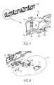
- FIG. 4Cis a cross-sectional view of an example carrier assembly in a bay showing ejection of the computer component according to one embodiment of the disclosure.
- FIG. 5is an example bracket implementing release mechanisms in several bays according to one embodiment of the disclosure.
- FIG. 6is an example installation of a bracket implementing release mechanisms in several bays according to one embodiment of the disclosure.
- FIG. 7is a detailed view of an example release mechanism attached to a bracket according to one embodiment of the disclosure.
- FIG. 8is an expanded view of an example release mechanism attached to a bracket according to one embodiment of the disclosure.
- FIG. 9is a detailed view showing an example carrier for a computer component configured to operate with a release mechanism according to one embodiment of the disclosure.
- FIG. 10is an expanded view showing an example carrier for a computer component configured to operate with a release mechanism according to one embodiment of the disclosure.
- a combination of components operating together within a chassiscan provide a user with easier insertion and removal of a computer component.
- the componentsmay allow a single user motion to perform multiple functions related to the installation or removal of the computer components.
- a levermay translate a user's applied force to perform one or more functions relating to unlocking the computer component, ejecting the computer component, and/or disconnecting cables or other fasteners from the computer component.
- a levermay unlock, eject, and disconnect cables from a computer component installed in a bay.
- a single cam levermay provide one or more functions that can be operated using familiar and simple user motions.
- the cam levermay provide a large easy-to-operate surface for a user to access and require only a simple motion to release a computer component from the bay. Additionally, using the same lever and the same simple motion the user may eject the computer component from the bay when releasing the computer component.
- FIG. 2A and FIG. 2BThe operation of inserting and locking a computer component, such as a hard disk drive (HDD), into a bay having a release mechanism according to one embodiment of the disclosure is shown in FIG. 2A and FIG. 2B .
- a computer componentsuch as a hard disk drive (HDD)
- FIG. 2Aillustrates the insertion of a carrier assembly 202 into a bay 230 prior to locking of the carrier assembly 202 in the bay 230 .
- FIG. 2Billustrates the carrier assembly 202 coupled to a bracket 212 in the bay 230 .
- an apparatus for receiving, locking, and releasing a computer component in a chassisgenerally includes two components.
- One componentis the carrier assembly 202 that attaches to and carries a computer component. These components are generally manufactured by OEMs separate from the manufacture and assembly of a computer system. The carrier assembly 202 thus allows for computer components from different manufacturers to be brought into conformity for a particular chassis.
- Another componentis a bracket for receiving the carrier assembly 202 that includes components for the locking and releasing of the carrier assembly 202 . In some embodiments, the bracket may fit in a chassis to divide space into a plurality of bays and provides components for the locking and releasing of the carrier assembly 202 in and out of each of the bays.
- the carrier assembly 202may house a computer component for storing data for reading and writing from a computer system. Attached to the carrier assembly 202 is a carrier latch 206 .
- the carrier latch 206may be used to lock the carrier assembly 202 to a bracket 212 of the bay 230 .
- the carrier latch 206may include features that assist with the locking and release of the carrier assembly 202 .
- the carrier latch 206may include a member 206 A near a distal end of the carrier latch 206 away from the drive. The member 206 A may be used to couple, such as to fix or engage, the carrier assembly 202 to the bracket 212 .
- the member 206 Ais an extrusion or protuberance that fits into an opening and provides resistance to the removal of the carrier assembly 202 after the member 206 A fits into the opening.
- the carrier latch 206may include a surface 206 B at a distal end of the carrier latch 206 away from the drive. The surface 206 B may be used to receive force that lifts the member 206 A to decouple the carrier latch 206 from the bracket 212 .
- the surface 206 Bmay be a flat surface. Additionally, in certain embodiments, the surface 206 B may be angled.
- the bracket 212may include a stopper flange 212 A.
- the stopper flange 212 Amay be configured to couple with the carrier latch 206 A. For example, sizing of the stopper flange 212 A may allow the carrier latch 206 to extend over the stopper flange 212 A and the member 206 A to lock in place over the stopper flange 212 A. The stopper flange 212 A then provides resistance to any attempted removal of the carrier assembly 202 from the bay 230 .
- a release mechanism 240to actuate the carrier latch 206 and decouple the carrier assembly 202 from the bracket 212 .
- the release mechanism 240may include a cam lever 214 with a surface 214 C for user operation.
- the cam lever 214may include features that translate a user's applied force to surface 214 C into appropriate motions for controlling the carrier assembly 202 .
- the cam lever 214may include a tip 214 A that abuts, but does not necessarily contact, the stopper flange 212 A.
- the tip 214 Amay be configured to apply force to the surface 206 B of the carrier latch 206 to decouple the carrier assembly 202 from the bracket 212 .
- the cam lever 214may include an edge 214 B located a short distance from the tip 214 A.
- the edge 214 Bmay be configured to apply force to the support bracket 204 to eject the carrier assembly 202 from the bay 230 .
- FIG. 2Aillustrates the carrier assembly 202 partially inserted into the bay 230 .
- a usermay apply force to a front (not shown) of the carrier assembly 202 or the drive mounted in the carrier assembly 202 to continue to insert the carrier assembly 202 into the bay 230 .
- FIG. 2Billustrates the carrier assembly 202 fully inserted and locked in bay 230 .
- the carrier latch 206couples to the stopper flange 212 A to lock the carrier assembly 202 in the bay.
- one or more cable connectors 220may couple one or more of data and power cables to a drive (not shown) within the carrier assembly 202 .
- Ejection of the carrier assembly 202 from the bay 230may be easily accomplished through operation of the cam lever 214 by a user.
- user operationmay include applying a force to the cam lever 214
- a userneed not physically apply the force.
- a usermay set into course actions that cause the cam lever 214 to be actuated.
- a usermay cause a servo or other mechanism to actuate the cam lever 214 or the user may program operation into a computer system such that the program activates a servo to actuate the cam lever 214 .
- FIG. 3is a flow chart showing an example method for releasing a computer component carrier assembly from a bay according to one embodiment of the disclosure.
- a method 300begins at block 302 with applying a first force to a lever, wherein a tip of the lever actuates a carrier latch of the carrier to release the latch from a locked position.
- the first forcemay rotate the lever cam 214 around a pivot point, such as may be provided by a pin, axel, or other component, to translate a downward force on surface 214 C to an upward force on the carrier latch 206 to elevate the carrier latch 206 above the stopper flange 212 A.
- a second subsequent forceis applied to the lever.
- the second forcemay cause the edge 214 B to apply a proportional amount of force to a support bracket 204 of the carrier assembly 202 to eject the carrier assembly 202 from the bay 230 .
- the first force and the subsequent forceare described as separate steps, they may be performed by a user in a single motion. That is, a single downward force on surface 214 C may cause the release and ejection of the carrier assembly 202 . This simple motion is easily performed by a user with, for example, a single finger.
- FIG. 4Aillustrates the locked state for the carrier assembly 202 in the bay 230 .
- the carrier latch 206is coupled to the stopper flange 212 A to secure the carrier assembly 202 in the bay 230 .
- a usermay execute the steps shown in FIG. 3 .
- a userapplies a downward force on surface 214 C, which causes the tip 214 A to press against the carrier latch 206 , such as against the member 206 A or the surface 206 B as shown in FIG. 4B .
- the member 206 Ais lifted above the stopper flange 212 A to unlock the carrier assembly 202 from the bay 230 .
- a usercontinues to apply a downward force on surface 214 C, which causes the edge 214 B to make contact with the support bracket 204 .
- Pressure applied to the support bracket 204pushes the carrier assembly 202 out of the front of the bay 230 as shown in FIG. 4C .
- the carrier assembly 202may be ejected by at least a small distance such that a user may grab the released carrier assembly 202 in the drive from the front of the chassis and pull the assembly 202 out of the chassis.
- FIG. 5is an example bracket implementing release mechanisms in several bays according to one embodiment of the disclosure.
- a bracket 500may divide the space inside the chassis (not shown) into multiple bays 502 .
- Each of the bays 502may have a locking and release mechanism 210 in close proximity and/or attached to the bracket 500 to receive, lock, and release a carrier assembly 202 having a locking mechanism 250 .
- the locking and release mechanisms 210are attached to the bracket 500 as shown in FIG. 6 .
- FIG. 6is an example installation of a bracket implementing release mechanisms in several bays for computer components according to one embodiment of the disclosure.
- Screws 604may attach a metal sheet 602 to the bracket 500 .
- the metal sheet 602may include the locking and release mechanisms 210 .
- FIG. 7is a detailed view of an example release mechanism attached to a bracket according to one embodiment of the disclosure.
- the locking and release mechanism 210may be attached to the metal sheet 602 by fasteners 702 , such as screws or bolts.
- a cable connector 220may likewise be attached to the metal sheet 602 by fasteners 704 , such as screws or bolts.
- the cable connector 220may include male connectors 720 A for receiving a data cable and may also include male connectors 720 B for receiving a power cable. Although male connectors are shown, the connectors may be either male or female.
- FIG. 8is an expanded view of an example release mechanism attached to a bracket according to one embodiment of the disclosure.
- the locking and release mechanism 210may include a cam 214 with an opening to receive pin 816 .
- Pin 816extends through an opening in casing 818 , through the cam 214 , and again through the casing 818 on an opposite side.
- a bias mechanism 820such as a spring may be coupled to the pin 816 and/or the cam 214 .
- the bias mechanism 820may be configured to return the cam 214 to a resting position after a user has applied force to cam 214 to rotate cam 214 around the pin 816 and release and eject a carrier assembly.
- the locking and release mechanism 210 of the bay 230may be configured to match a locking mechanism 250 on a carrier assembly 202 .
- a more detailed view of the locking mechanism 250is shown in FIG. 9 .
- FIG. 9is a detailed view showing an example carrier for a computer configured to operate with a release mechanism according to one embodiment of the disclosure.
- the carrier assembly 202may include a cage 902 that may partially or completely surround a computer component. Additional pieces may attach to the cage 902 to provide locking and release capability when used in cooperation with the locking and release mechanism 210 of the bay 230 . Examples of such additional pieces are shown in the expanded view of FIG. 10 .
- FIG. 10is an expanded view showing an example carrier for a computer component configured to operate with a release mechanism according to one embodiment of the disclosure.
- a metal piece 1004 with a carrier latch 206may attach to the cage 902 .
- a plastic piece 1006 with the support bracket 204may attach to the cage 902 . Openings in the metal piece 1004 and the plastic piece 1006 may align to allow a single fastener, such as a screw or bolt, to attach both pieces 1004 and 1006 to the cage 902 .
- an information handling systemmay include any instrumentality or aggregate of instrumentalities operable to compute, calculate, determine, classify, process, transmit, receive, retrieve, originate, switch, store, display, communicate, manifest, detect, record, reproduce, handle, or utilize any form of information, intelligence, or data for business, scientific, control, or other purposes.
- an information handling systemmay be a personal computer (e.g., desktop or laptop), tablet computer, mobile device (e.g., personal digital assistant (PDA) or smart phone), server (e.g., blade server or rack server), a network storage device, or any other suitable device and may vary in size, shape, performance, functionality, and price.
- the information handling systemmay include random access memory (RAM), one or more processing resources such as a central processing unit (CPU) or hardware or software control logic, ROM, and/or other types of nonvolatile memory. Additional components of the information handling system may include one or more disk drives, one or more network ports for communicating with external devices as well as various input and output (I/O) devices, such as a keyboard, a mouse, touchscreen and/or a video display.
- RAMrandom access memory
- processing resourcessuch as a central processing unit (CPU) or hardware or software control logic
- ROMread-only memory
- Additional components of the information handling systemmay include one or more disk drives, one or more network ports for communicating with external devices as well as various input and output (I/O) devices, such as a keyboard, a mouse, touchscreen and/or a video display.
- I/Oinput and output
- the information handling systemmay also include one or more buses operable to transmit communications between the various hardware components. Any of these components may be mounted in a carrier and operated with a lever mechanism as
- the schematic flow chart diagram of FIG. 3is generally set forth as a logical flow chart diagram. As such, the depicted order and labeled steps are indicative of aspects of the disclosed method. Other steps and methods may be conceived that are equivalent in function, logic, or effect to one or more steps, or portions thereof, of the illustrated method. Additionally, the format and symbols employed are provided to explain the logical steps of the method and are understood not to limit the scope of the method. Although various arrow types and line types may be employed in the flow chart diagram, they are understood not to limit the scope of the corresponding method. Indeed, some arrows or other connectors may be used to indicate only the logical flow of the method. For instance, an arrow may indicate a waiting or monitoring period of unspecified duration between enumerated steps of the depicted method. Additionally, the order in which a particular method occurs may or may not strictly adhere to the order of the corresponding steps shown.
Landscapes
- Engineering & Computer Science (AREA)
- Theoretical Computer Science (AREA)
- Computer Hardware Design (AREA)
- Human Computer Interaction (AREA)
- Physics & Mathematics (AREA)
- General Engineering & Computer Science (AREA)
- General Physics & Mathematics (AREA)
- Power Engineering (AREA)
- Details Of Connecting Devices For Male And Female Coupling (AREA)
Abstract
Description
Claims (9)
Priority Applications (1)
| Application Number | Priority Date | Filing Date | Title |
|---|---|---|---|
| US15/093,605US9841790B2 (en) | 2016-04-07 | 2016-04-07 | Lever release mechanism for a computer component |
Applications Claiming Priority (1)
| Application Number | Priority Date | Filing Date | Title |
|---|---|---|---|
| US15/093,605US9841790B2 (en) | 2016-04-07 | 2016-04-07 | Lever release mechanism for a computer component |
Publications (2)
| Publication Number | Publication Date |
|---|---|
| US20170293326A1 US20170293326A1 (en) | 2017-10-12 |
| US9841790B2true US9841790B2 (en) | 2017-12-12 |
Family
ID=59999344
Family Applications (1)
| Application Number | Title | Priority Date | Filing Date |
|---|---|---|---|
| US15/093,605ActiveUS9841790B2 (en) | 2016-04-07 | 2016-04-07 | Lever release mechanism for a computer component |
Country Status (1)
| Country | Link |
|---|---|
| US (1) | US9841790B2 (en) |
Cited By (1)
| Publication number | Priority date | Publication date | Assignee | Title |
|---|---|---|---|---|
| US11606874B2 (en) | 2021-03-18 | 2023-03-14 | Dell Products L.P. | Tolerance absorbing lever mechanism |
Families Citing this family (4)
| Publication number | Priority date | Publication date | Assignee | Title |
|---|---|---|---|---|
| US10095281B2 (en)* | 2017-02-16 | 2018-10-09 | Lite-On Electronics (Guangzhou) Limited | Fixing mechanism and computer chassis |
| CN111051945B (en)* | 2017-06-28 | 2023-12-29 | 康宁研究与开发公司 | Compact fiber optic connector, cable assembly and method of making the same |
| US10925186B2 (en)* | 2019-05-15 | 2021-02-16 | Hewlett Packard Enterprise Development Lp | Vertical lift heat transfer device for pluggable modules |
| JP7653591B2 (en)* | 2021-02-26 | 2025-03-31 | パナソニックIpマネジメント株式会社 | Electronics |
Citations (7)
| Publication number | Priority date | Publication date | Assignee | Title |
|---|---|---|---|---|
| US5379184A (en)* | 1991-08-30 | 1995-01-03 | Unisys Corporation | Pry-in/pry-out disk drive receptacle |
| US6252514B1 (en)* | 1999-06-07 | 2001-06-26 | Convergent Technologies, Inc. | Hot-swap assembly for computers |
| US6325353B1 (en)* | 1999-03-08 | 2001-12-04 | Intel Corporation | Carrier for disk drive hot swapping |
| US6774808B1 (en)* | 2000-05-17 | 2004-08-10 | Dell Products L.P. | Electromechanical lock for components |
| US20110080705A1 (en)* | 2009-10-06 | 2011-04-07 | Dell Products L.P. | Controlled Compression Of Hard Drive Carrier CAM |
| US20110096490A1 (en)* | 2009-10-23 | 2011-04-28 | Dell Products L.P. | Peripheral Device Carrying Apparatus and Systems |
| US8743536B2 (en)* | 2011-05-24 | 2014-06-03 | International Business Machines Corporation | Mechanical conversion sleeve |
- 2016
- 2016-04-07USUS15/093,605patent/US9841790B2/enactiveActive
Patent Citations (9)
| Publication number | Priority date | Publication date | Assignee | Title |
|---|---|---|---|---|
| US5379184A (en)* | 1991-08-30 | 1995-01-03 | Unisys Corporation | Pry-in/pry-out disk drive receptacle |
| US6325353B1 (en)* | 1999-03-08 | 2001-12-04 | Intel Corporation | Carrier for disk drive hot swapping |
| US20020080574A1 (en)* | 1999-03-08 | 2002-06-27 | Jiang Kevin G. | Carrier for disk drive hot swapping |
| US6854174B2 (en)* | 1999-03-08 | 2005-02-15 | Intel Corporation | Method for inserting a disk drive into a peripheral bay chassis |
| US6252514B1 (en)* | 1999-06-07 | 2001-06-26 | Convergent Technologies, Inc. | Hot-swap assembly for computers |
| US6774808B1 (en)* | 2000-05-17 | 2004-08-10 | Dell Products L.P. | Electromechanical lock for components |
| US20110080705A1 (en)* | 2009-10-06 | 2011-04-07 | Dell Products L.P. | Controlled Compression Of Hard Drive Carrier CAM |
| US20110096490A1 (en)* | 2009-10-23 | 2011-04-28 | Dell Products L.P. | Peripheral Device Carrying Apparatus and Systems |
| US8743536B2 (en)* | 2011-05-24 | 2014-06-03 | International Business Machines Corporation | Mechanical conversion sleeve |
Cited By (1)
| Publication number | Priority date | Publication date | Assignee | Title |
|---|---|---|---|---|
| US11606874B2 (en) | 2021-03-18 | 2023-03-14 | Dell Products L.P. | Tolerance absorbing lever mechanism |
Also Published As
| Publication number | Publication date |
|---|---|
| US20170293326A1 (en) | 2017-10-12 |
Similar Documents
| Publication | Publication Date | Title |
|---|---|---|
| US9841790B2 (en) | Lever release mechanism for a computer component | |
| US7507112B2 (en) | Low insertion force connector coupling | |
| US9161476B2 (en) | Locking mechanism for adaptor assembly of a server rack chassis | |
| US9437250B2 (en) | Hard drive carrier that locks in a shipping position | |
| US11095445B2 (en) | Key management and recovery | |
| US7826210B2 (en) | Sliding front carriage for an information handling system chassis | |
| US7576979B1 (en) | Modular Server handle | |
| US10365697B2 (en) | Hot plug carrier with push to release mechanism | |
| US20210298193A1 (en) | Server device | |
| US10405453B1 (en) | Systems and methods for carrier-less storage device extraction in an information handling system | |
| US8144463B2 (en) | Card retention system | |
| US7684188B2 (en) | Media base security device and method of use | |
| US11558974B2 (en) | Integrated safety latch for cold swap only devices | |
| CN109254880B (en) | Method and device for processing database downtime | |
| US11552840B2 (en) | Intention-based device component tracking system | |
| US20210273379A1 (en) | Network port connector ejection system | |
| US11894024B2 (en) | Information handling system storage drive carrier | |
| US11758674B2 (en) | Latch with movable handle for electronic equipment | |
| US11606874B2 (en) | Tolerance absorbing lever mechanism | |
| US11646532B1 (en) | Connector release system | |
| US11841750B2 (en) | Interchangeable labeling strip in chassis hem | |
| US10747706B2 (en) | Server event log storage and retrieval system | |
| US11324137B2 (en) | Systems and methods for mounting air mover to create thermal seal and minimize vibrational noise | |
| US10206304B2 (en) | Latching assembly | |
| NL2036248B1 (en) | Chassis structure |
Legal Events
| Date | Code | Title | Description |
|---|---|---|---|
| AS | Assignment | Owner name:DELL PRODUCTS L.P., TEXAS Free format text:ASSIGNMENT OF ASSIGNORS INTEREST;ASSIGNORS:LIN, KUANG HSI;KUO, WEI-TI;CHANG, LING CHEN;AND OTHERS;SIGNING DATES FROM 20160401 TO 20160406;REEL/FRAME:038242/0459 | |
| AS | Assignment | Owner name:BANK OF AMERICA, N.A., AS ADMINISTRATIVE AGENT, NORTH CAROLINA Free format text:SUPPLEMENT TO PATENT SECURITY AGREEMENT (ABL);ASSIGNORS:DELL PRODUCTS L.P.;DELL SOFTWARE INC.;WYSE TECHNOLOGY, L.L.C.;REEL/FRAME:038665/0001 Effective date:20160511 Owner name:THE BANK OF NEW YORK MELLON TRUST COMPANY, N.A., AS FIRST LIEN COLLATERAL AGENT, TEXAS Free format text:SUPPLEMENT TO PATENT SECURITY AGREEMENT (NOTES);ASSIGNORS:DELL SOFTWARE INC.;WYSE TECHNOLOGY, L.L.C.;DELL PRODUCTS L.P.;REEL/FRAME:038664/0908 Effective date:20160511 Owner name:BANK OF AMERICA, N.A., AS COLLATERAL AGENT, NORTH CAROLINA Free format text:SUPPLEMENT TO PATENT SECURITY AGREEMENT (TERM LOAN);ASSIGNORS:DELL PRODUCTS L.P.;DELL SOFTWARE INC.;WYSE TECHNOLOGY, L.L.C.;REEL/FRAME:038665/0041 Effective date:20160511 Owner name:BANK OF AMERICA, N.A., AS ADMINISTRATIVE AGENT, NO Free format text:SUPPLEMENT TO PATENT SECURITY AGREEMENT (ABL);ASSIGNORS:DELL PRODUCTS L.P.;DELL SOFTWARE INC.;WYSE TECHNOLOGY, L.L.C.;REEL/FRAME:038665/0001 Effective date:20160511 Owner name:THE BANK OF NEW YORK MELLON TRUST COMPANY, N.A., A Free format text:SUPPLEMENT TO PATENT SECURITY AGREEMENT (NOTES);ASSIGNORS:DELL SOFTWARE INC.;WYSE TECHNOLOGY, L.L.C.;DELL PRODUCTS L.P.;REEL/FRAME:038664/0908 Effective date:20160511 Owner name:BANK OF AMERICA, N.A., AS COLLATERAL AGENT, NORTH Free format text:SUPPLEMENT TO PATENT SECURITY AGREEMENT (TERM LOAN);ASSIGNORS:DELL PRODUCTS L.P.;DELL SOFTWARE INC.;WYSE TECHNOLOGY, L.L.C.;REEL/FRAME:038665/0041 Effective date:20160511 | |
| AS | Assignment | Owner name:SECUREWORKS, CORP., GEORGIA Free format text:RELEASE OF REEL 038665 FRAME 0001 (ABL);ASSIGNOR:BANK OF AMERICA, N.A., AS ADMINISTRATIVE AGENT;REEL/FRAME:040021/0348 Effective date:20160907 Owner name:DELL SOFTWARE INC., CALIFORNIA Free format text:RELEASE OF REEL 038665 FRAME 0001 (ABL);ASSIGNOR:BANK OF AMERICA, N.A., AS ADMINISTRATIVE AGENT;REEL/FRAME:040021/0348 Effective date:20160907 Owner name:WYSE TECHNOLOGY L.L.C., CALIFORNIA Free format text:RELEASE OF REEL 038665 FRAME 0001 (ABL);ASSIGNOR:BANK OF AMERICA, N.A., AS ADMINISTRATIVE AGENT;REEL/FRAME:040021/0348 Effective date:20160907 Owner name:DELL PRODUCTS L.P., TEXAS Free format text:RELEASE OF REEL 038665 FRAME 0001 (ABL);ASSIGNOR:BANK OF AMERICA, N.A., AS ADMINISTRATIVE AGENT;REEL/FRAME:040021/0348 Effective date:20160907 | |
| AS | Assignment | Owner name:WYSE TECHNOLOGY L.L.C., CALIFORNIA Free format text:RELEASE OF REEL 038665 FRAME 0041 (TL);ASSIGNOR:BANK OF AMERICA, N.A., AS COLLATERAL AGENT;REEL/FRAME:040028/0375 Effective date:20160907 Owner name:DELL PRODUCTS L.P., TEXAS Free format text:RELEASE OF REEL 038665 FRAME 0041 (TL);ASSIGNOR:BANK OF AMERICA, N.A., AS COLLATERAL AGENT;REEL/FRAME:040028/0375 Effective date:20160907 Owner name:DELL SOFTWARE INC., CALIFORNIA Free format text:RELEASE OF REEL 038664 FRAME 0908 (NOTE);ASSIGNOR:BANK OF NEW YORK MELLON TRUST COMPANY, N.A., AS COLLATERAL AGENT;REEL/FRAME:040027/0390 Effective date:20160907 Owner name:SECUREWORKS, CORP., GEORGIA Free format text:RELEASE OF REEL 038664 FRAME 0908 (NOTE);ASSIGNOR:BANK OF NEW YORK MELLON TRUST COMPANY, N.A., AS COLLATERAL AGENT;REEL/FRAME:040027/0390 Effective date:20160907 Owner name:DELL PRODUCTS L.P., TEXAS Free format text:RELEASE OF REEL 038664 FRAME 0908 (NOTE);ASSIGNOR:BANK OF NEW YORK MELLON TRUST COMPANY, N.A., AS COLLATERAL AGENT;REEL/FRAME:040027/0390 Effective date:20160907 Owner name:DELL SOFTWARE INC., CALIFORNIA Free format text:RELEASE OF REEL 038665 FRAME 0041 (TL);ASSIGNOR:BANK OF AMERICA, N.A., AS COLLATERAL AGENT;REEL/FRAME:040028/0375 Effective date:20160907 Owner name:WYSE TECHNOLOGY L.L.C., CALIFORNIA Free format text:RELEASE OF REEL 038664 FRAME 0908 (NOTE);ASSIGNOR:BANK OF NEW YORK MELLON TRUST COMPANY, N.A., AS COLLATERAL AGENT;REEL/FRAME:040027/0390 Effective date:20160907 Owner name:SECUREWORKS, CORP., GEORGIA Free format text:RELEASE OF REEL 038665 FRAME 0041 (TL);ASSIGNOR:BANK OF AMERICA, N.A., AS COLLATERAL AGENT;REEL/FRAME:040028/0375 Effective date:20160907 | |
| AS | Assignment | Owner name:THE BANK OF NEW YORK MELLON TRUST COMPANY, N.A., AS NOTES COLLATERAL AGENT, TEXAS Free format text:SECURITY AGREEMENT;ASSIGNORS:ASAP SOFTWARE EXPRESS, INC.;AVENTAIL LLC;CREDANT TECHNOLOGIES, INC.;AND OTHERS;REEL/FRAME:040136/0001 Effective date:20160907 Owner name:CREDIT SUISSE AG, CAYMAN ISLANDS BRANCH, AS COLLATERAL AGENT, NORTH CAROLINA Free format text:SECURITY AGREEMENT;ASSIGNORS:ASAP SOFTWARE EXPRESS, INC.;AVENTAIL LLC;CREDANT TECHNOLOGIES, INC.;AND OTHERS;REEL/FRAME:040134/0001 Effective date:20160907 Owner name:CREDIT SUISSE AG, CAYMAN ISLANDS BRANCH, AS COLLAT Free format text:SECURITY AGREEMENT;ASSIGNORS:ASAP SOFTWARE EXPRESS, INC.;AVENTAIL LLC;CREDANT TECHNOLOGIES, INC.;AND OTHERS;REEL/FRAME:040134/0001 Effective date:20160907 Owner name:THE BANK OF NEW YORK MELLON TRUST COMPANY, N.A., A Free format text:SECURITY AGREEMENT;ASSIGNORS:ASAP SOFTWARE EXPRESS, INC.;AVENTAIL LLC;CREDANT TECHNOLOGIES, INC.;AND OTHERS;REEL/FRAME:040136/0001 Effective date:20160907 | |
| STCF | Information on status: patent grant | Free format text:PATENTED CASE | |
| AS | Assignment | Owner name:THE BANK OF NEW YORK MELLON TRUST COMPANY, N.A., T Free format text:SECURITY AGREEMENT;ASSIGNORS:CREDANT TECHNOLOGIES, INC.;DELL INTERNATIONAL L.L.C.;DELL MARKETING L.P.;AND OTHERS;REEL/FRAME:049452/0223 Effective date:20190320 Owner name:THE BANK OF NEW YORK MELLON TRUST COMPANY, N.A., TEXAS Free format text:SECURITY AGREEMENT;ASSIGNORS:CREDANT TECHNOLOGIES, INC.;DELL INTERNATIONAL L.L.C.;DELL MARKETING L.P.;AND OTHERS;REEL/FRAME:049452/0223 Effective date:20190320 | |
| AS | Assignment | Owner name:THE BANK OF NEW YORK MELLON TRUST COMPANY, N.A., TEXAS Free format text:SECURITY AGREEMENT;ASSIGNORS:CREDANT TECHNOLOGIES INC.;DELL INTERNATIONAL L.L.C.;DELL MARKETING L.P.;AND OTHERS;REEL/FRAME:053546/0001 Effective date:20200409 | |
| MAFP | Maintenance fee payment | Free format text:PAYMENT OF MAINTENANCE FEE, 4TH YEAR, LARGE ENTITY (ORIGINAL EVENT CODE: M1551); ENTITY STATUS OF PATENT OWNER: LARGE ENTITY Year of fee payment:4 | |
| AS | Assignment | Owner name:WYSE TECHNOLOGY L.L.C., CALIFORNIA Free format text:RELEASE BY SECURED PARTY;ASSIGNOR:CREDIT SUISSE AG, CAYMAN ISLANDS BRANCH;REEL/FRAME:058216/0001 Effective date:20211101 Owner name:SCALEIO LLC, MASSACHUSETTS Free format text:RELEASE BY SECURED PARTY;ASSIGNOR:CREDIT SUISSE AG, CAYMAN ISLANDS BRANCH;REEL/FRAME:058216/0001 Effective date:20211101 Owner name:MOZY, INC., WASHINGTON Free format text:RELEASE BY SECURED PARTY;ASSIGNOR:CREDIT SUISSE AG, CAYMAN ISLANDS BRANCH;REEL/FRAME:058216/0001 Effective date:20211101 Owner name:MAGINATICS LLC, CALIFORNIA Free format text:RELEASE BY SECURED PARTY;ASSIGNOR:CREDIT SUISSE AG, CAYMAN ISLANDS BRANCH;REEL/FRAME:058216/0001 Effective date:20211101 Owner name:FORCE10 NETWORKS, INC., CALIFORNIA Free format text:RELEASE BY SECURED PARTY;ASSIGNOR:CREDIT SUISSE AG, CAYMAN ISLANDS BRANCH;REEL/FRAME:058216/0001 Effective date:20211101 Owner name:EMC IP HOLDING COMPANY LLC, TEXAS Free format text:RELEASE BY SECURED PARTY;ASSIGNOR:CREDIT SUISSE AG, CAYMAN ISLANDS BRANCH;REEL/FRAME:058216/0001 Effective date:20211101 Owner name:EMC CORPORATION, MASSACHUSETTS Free format text:RELEASE BY SECURED PARTY;ASSIGNOR:CREDIT SUISSE AG, CAYMAN ISLANDS BRANCH;REEL/FRAME:058216/0001 Effective date:20211101 Owner name:DELL SYSTEMS CORPORATION, TEXAS Free format text:RELEASE BY SECURED PARTY;ASSIGNOR:CREDIT SUISSE AG, CAYMAN ISLANDS BRANCH;REEL/FRAME:058216/0001 Effective date:20211101 Owner name:DELL SOFTWARE INC., CALIFORNIA Free format text:RELEASE BY SECURED PARTY;ASSIGNOR:CREDIT SUISSE AG, CAYMAN ISLANDS BRANCH;REEL/FRAME:058216/0001 Effective date:20211101 Owner name:DELL PRODUCTS L.P., TEXAS Free format text:RELEASE BY SECURED PARTY;ASSIGNOR:CREDIT SUISSE AG, CAYMAN ISLANDS BRANCH;REEL/FRAME:058216/0001 Effective date:20211101 Owner name:DELL MARKETING L.P., TEXAS Free format text:RELEASE BY SECURED PARTY;ASSIGNOR:CREDIT SUISSE AG, CAYMAN ISLANDS BRANCH;REEL/FRAME:058216/0001 Effective date:20211101 Owner name:DELL INTERNATIONAL, L.L.C., TEXAS Free format text:RELEASE BY SECURED PARTY;ASSIGNOR:CREDIT SUISSE AG, CAYMAN ISLANDS BRANCH;REEL/FRAME:058216/0001 Effective date:20211101 Owner name:DELL USA L.P., TEXAS Free format text:RELEASE BY SECURED PARTY;ASSIGNOR:CREDIT SUISSE AG, CAYMAN ISLANDS BRANCH;REEL/FRAME:058216/0001 Effective date:20211101 Owner name:CREDANT TECHNOLOGIES, INC., TEXAS Free format text:RELEASE BY SECURED PARTY;ASSIGNOR:CREDIT SUISSE AG, CAYMAN ISLANDS BRANCH;REEL/FRAME:058216/0001 Effective date:20211101 Owner name:AVENTAIL LLC, CALIFORNIA Free format text:RELEASE BY SECURED PARTY;ASSIGNOR:CREDIT SUISSE AG, CAYMAN ISLANDS BRANCH;REEL/FRAME:058216/0001 Effective date:20211101 Owner name:ASAP SOFTWARE EXPRESS, INC., ILLINOIS Free format text:RELEASE BY SECURED PARTY;ASSIGNOR:CREDIT SUISSE AG, CAYMAN ISLANDS BRANCH;REEL/FRAME:058216/0001 Effective date:20211101 | |
| AS | Assignment | Owner name:SCALEIO LLC, MASSACHUSETTS Free format text:RELEASE OF SECURITY INTEREST IN PATENTS PREVIOUSLY RECORDED AT REEL/FRAME (040136/0001);ASSIGNOR:THE BANK OF NEW YORK MELLON TRUST COMPANY, N.A., AS NOTES COLLATERAL AGENT;REEL/FRAME:061324/0001 Effective date:20220329 Owner name:EMC IP HOLDING COMPANY LLC (ON BEHALF OF ITSELF AND AS SUCCESSOR-IN-INTEREST TO MOZY, INC.), TEXAS Free format text:RELEASE OF SECURITY INTEREST IN PATENTS PREVIOUSLY RECORDED AT REEL/FRAME (040136/0001);ASSIGNOR:THE BANK OF NEW YORK MELLON TRUST COMPANY, N.A., AS NOTES COLLATERAL AGENT;REEL/FRAME:061324/0001 Effective date:20220329 Owner name:EMC CORPORATION (ON BEHALF OF ITSELF AND AS SUCCESSOR-IN-INTEREST TO MAGINATICS LLC), MASSACHUSETTS Free format text:RELEASE OF SECURITY INTEREST IN PATENTS PREVIOUSLY RECORDED AT REEL/FRAME (040136/0001);ASSIGNOR:THE BANK OF NEW YORK MELLON TRUST COMPANY, N.A., AS NOTES COLLATERAL AGENT;REEL/FRAME:061324/0001 Effective date:20220329 Owner name:DELL MARKETING CORPORATION (SUCCESSOR-IN-INTEREST TO FORCE10 NETWORKS, INC. AND WYSE TECHNOLOGY L.L.C.), TEXAS Free format text:RELEASE OF SECURITY INTEREST IN PATENTS PREVIOUSLY RECORDED AT REEL/FRAME (040136/0001);ASSIGNOR:THE BANK OF NEW YORK MELLON TRUST COMPANY, N.A., AS NOTES COLLATERAL AGENT;REEL/FRAME:061324/0001 Effective date:20220329 Owner name:DELL PRODUCTS L.P., TEXAS Free format text:RELEASE OF SECURITY INTEREST IN PATENTS PREVIOUSLY RECORDED AT REEL/FRAME (040136/0001);ASSIGNOR:THE BANK OF NEW YORK MELLON TRUST COMPANY, N.A., AS NOTES COLLATERAL AGENT;REEL/FRAME:061324/0001 Effective date:20220329 Owner name:DELL INTERNATIONAL L.L.C., TEXAS Free format text:RELEASE OF SECURITY INTEREST IN PATENTS PREVIOUSLY RECORDED AT REEL/FRAME (040136/0001);ASSIGNOR:THE BANK OF NEW YORK MELLON TRUST COMPANY, N.A., AS NOTES COLLATERAL AGENT;REEL/FRAME:061324/0001 Effective date:20220329 Owner name:DELL USA L.P., TEXAS Free format text:RELEASE OF SECURITY INTEREST IN PATENTS PREVIOUSLY RECORDED AT REEL/FRAME (040136/0001);ASSIGNOR:THE BANK OF NEW YORK MELLON TRUST COMPANY, N.A., AS NOTES COLLATERAL AGENT;REEL/FRAME:061324/0001 Effective date:20220329 Owner name:DELL MARKETING L.P. (ON BEHALF OF ITSELF AND AS SUCCESSOR-IN-INTEREST TO CREDANT TECHNOLOGIES, INC.), TEXAS Free format text:RELEASE OF SECURITY INTEREST IN PATENTS PREVIOUSLY RECORDED AT REEL/FRAME (040136/0001);ASSIGNOR:THE BANK OF NEW YORK MELLON TRUST COMPANY, N.A., AS NOTES COLLATERAL AGENT;REEL/FRAME:061324/0001 Effective date:20220329 Owner name:DELL MARKETING CORPORATION (SUCCESSOR-IN-INTEREST TO ASAP SOFTWARE EXPRESS, INC.), TEXAS Free format text:RELEASE OF SECURITY INTEREST IN PATENTS PREVIOUSLY RECORDED AT REEL/FRAME (040136/0001);ASSIGNOR:THE BANK OF NEW YORK MELLON TRUST COMPANY, N.A., AS NOTES COLLATERAL AGENT;REEL/FRAME:061324/0001 Effective date:20220329 | |
| AS | Assignment | Owner name:SCALEIO LLC, MASSACHUSETTS Free format text:RELEASE OF SECURITY INTEREST IN PATENTS PREVIOUSLY RECORDED AT REEL/FRAME (045455/0001);ASSIGNOR:THE BANK OF NEW YORK MELLON TRUST COMPANY, N.A., AS NOTES COLLATERAL AGENT;REEL/FRAME:061753/0001 Effective date:20220329 Owner name:EMC IP HOLDING COMPANY LLC (ON BEHALF OF ITSELF AND AS SUCCESSOR-IN-INTEREST TO MOZY, INC.), TEXAS Free format text:RELEASE OF SECURITY INTEREST IN PATENTS PREVIOUSLY RECORDED AT REEL/FRAME (045455/0001);ASSIGNOR:THE BANK OF NEW YORK MELLON TRUST COMPANY, N.A., AS NOTES COLLATERAL AGENT;REEL/FRAME:061753/0001 Effective date:20220329 Owner name:EMC CORPORATION (ON BEHALF OF ITSELF AND AS SUCCESSOR-IN-INTEREST TO MAGINATICS LLC), MASSACHUSETTS Free format text:RELEASE OF SECURITY INTEREST IN PATENTS PREVIOUSLY RECORDED AT REEL/FRAME (045455/0001);ASSIGNOR:THE BANK OF NEW YORK MELLON TRUST COMPANY, N.A., AS NOTES COLLATERAL AGENT;REEL/FRAME:061753/0001 Effective date:20220329 Owner name:DELL MARKETING CORPORATION (SUCCESSOR-IN-INTEREST TO FORCE10 NETWORKS, INC. AND WYSE TECHNOLOGY L.L.C.), TEXAS Free format text:RELEASE OF SECURITY INTEREST IN PATENTS PREVIOUSLY RECORDED AT REEL/FRAME (045455/0001);ASSIGNOR:THE BANK OF NEW YORK MELLON TRUST COMPANY, N.A., AS NOTES COLLATERAL AGENT;REEL/FRAME:061753/0001 Effective date:20220329 Owner name:DELL PRODUCTS L.P., TEXAS Free format text:RELEASE OF SECURITY INTEREST IN PATENTS PREVIOUSLY RECORDED AT REEL/FRAME (045455/0001);ASSIGNOR:THE BANK OF NEW YORK MELLON TRUST COMPANY, N.A., AS NOTES COLLATERAL AGENT;REEL/FRAME:061753/0001 Effective date:20220329 Owner name:DELL INTERNATIONAL L.L.C., TEXAS Free format text:RELEASE OF SECURITY INTEREST IN PATENTS PREVIOUSLY RECORDED AT REEL/FRAME (045455/0001);ASSIGNOR:THE BANK OF NEW YORK MELLON TRUST COMPANY, N.A., AS NOTES COLLATERAL AGENT;REEL/FRAME:061753/0001 Effective date:20220329 Owner name:DELL USA L.P., TEXAS Free format text:RELEASE OF SECURITY INTEREST IN PATENTS PREVIOUSLY RECORDED AT REEL/FRAME (045455/0001);ASSIGNOR:THE BANK OF NEW YORK MELLON TRUST COMPANY, N.A., AS NOTES COLLATERAL AGENT;REEL/FRAME:061753/0001 Effective date:20220329 Owner name:DELL MARKETING L.P. (ON BEHALF OF ITSELF AND AS SUCCESSOR-IN-INTEREST TO CREDANT TECHNOLOGIES, INC.), TEXAS Free format text:RELEASE OF SECURITY INTEREST IN PATENTS PREVIOUSLY RECORDED AT REEL/FRAME (045455/0001);ASSIGNOR:THE BANK OF NEW YORK MELLON TRUST COMPANY, N.A., AS NOTES COLLATERAL AGENT;REEL/FRAME:061753/0001 Effective date:20220329 Owner name:DELL MARKETING CORPORATION (SUCCESSOR-IN-INTEREST TO ASAP SOFTWARE EXPRESS, INC.), TEXAS Free format text:RELEASE OF SECURITY INTEREST IN PATENTS PREVIOUSLY RECORDED AT REEL/FRAME (045455/0001);ASSIGNOR:THE BANK OF NEW YORK MELLON TRUST COMPANY, N.A., AS NOTES COLLATERAL AGENT;REEL/FRAME:061753/0001 Effective date:20220329 | |
| AS | Assignment | Owner name:DELL MARKETING L.P. (ON BEHALF OF ITSELF AND AS SUCCESSOR-IN-INTEREST TO CREDANT TECHNOLOGIES, INC.), TEXAS Free format text:RELEASE OF SECURITY INTEREST IN PATENTS PREVIOUSLY RECORDED AT REEL/FRAME (053546/0001);ASSIGNOR:THE BANK OF NEW YORK MELLON TRUST COMPANY, N.A., AS NOTES COLLATERAL AGENT;REEL/FRAME:071642/0001 Effective date:20220329 Owner name:DELL INTERNATIONAL L.L.C., TEXAS Free format text:RELEASE OF SECURITY INTEREST IN PATENTS PREVIOUSLY RECORDED AT REEL/FRAME (053546/0001);ASSIGNOR:THE BANK OF NEW YORK MELLON TRUST COMPANY, N.A., AS NOTES COLLATERAL AGENT;REEL/FRAME:071642/0001 Effective date:20220329 Owner name:DELL PRODUCTS L.P., TEXAS Free format text:RELEASE OF SECURITY INTEREST IN PATENTS PREVIOUSLY RECORDED AT REEL/FRAME (053546/0001);ASSIGNOR:THE BANK OF NEW YORK MELLON TRUST COMPANY, N.A., AS NOTES COLLATERAL AGENT;REEL/FRAME:071642/0001 Effective date:20220329 Owner name:DELL USA L.P., TEXAS Free format text:RELEASE OF SECURITY INTEREST IN PATENTS PREVIOUSLY RECORDED AT REEL/FRAME (053546/0001);ASSIGNOR:THE BANK OF NEW YORK MELLON TRUST COMPANY, N.A., AS NOTES COLLATERAL AGENT;REEL/FRAME:071642/0001 Effective date:20220329 Owner name:EMC CORPORATION, MASSACHUSETTS Free format text:RELEASE OF SECURITY INTEREST IN PATENTS PREVIOUSLY RECORDED AT REEL/FRAME (053546/0001);ASSIGNOR:THE BANK OF NEW YORK MELLON TRUST COMPANY, N.A., AS NOTES COLLATERAL AGENT;REEL/FRAME:071642/0001 Effective date:20220329 Owner name:DELL MARKETING CORPORATION (SUCCESSOR-IN-INTEREST TO FORCE10 NETWORKS, INC. AND WYSE TECHNOLOGY L.L.C.), TEXAS Free format text:RELEASE OF SECURITY INTEREST IN PATENTS PREVIOUSLY RECORDED AT REEL/FRAME (053546/0001);ASSIGNOR:THE BANK OF NEW YORK MELLON TRUST COMPANY, N.A., AS NOTES COLLATERAL AGENT;REEL/FRAME:071642/0001 Effective date:20220329 Owner name:EMC IP HOLDING COMPANY LLC, TEXAS Free format text:RELEASE OF SECURITY INTEREST IN PATENTS PREVIOUSLY RECORDED AT REEL/FRAME (053546/0001);ASSIGNOR:THE BANK OF NEW YORK MELLON TRUST COMPANY, N.A., AS NOTES COLLATERAL AGENT;REEL/FRAME:071642/0001 Effective date:20220329 | |
| FEPP | Fee payment procedure | Free format text:MAINTENANCE FEE REMINDER MAILED (ORIGINAL EVENT CODE: REM.); ENTITY STATUS OF PATENT OWNER: LARGE ENTITY |