US9841566B2 - Fiber optic connector - Google Patents
Fiber optic connectorDownload PDFInfo
- Publication number
- US9841566B2 US9841566B2US15/357,030US201615357030AUS9841566B2US 9841566 B2US9841566 B2US 9841566B2US 201615357030 AUS201615357030 AUS 201615357030AUS 9841566 B2US9841566 B2US 9841566B2
- Authority
- US
- United States
- Prior art keywords
- fiber optic
- connector
- fiber
- proximal
- optic connector
- Prior art date
- Legal status (The legal status is an assumption and is not a legal conclusion. Google has not performed a legal analysis and makes no representation as to the accuracy of the status listed.)
- Expired - Fee Related
Links
Images


Classifications
- G—PHYSICS
- G02—OPTICS
- G02B—OPTICAL ELEMENTS, SYSTEMS OR APPARATUS
- G02B6/00—Light guides; Structural details of arrangements comprising light guides and other optical elements, e.g. couplings
- G02B6/24—Coupling light guides
- G02B6/36—Mechanical coupling means
- G02B6/38—Mechanical coupling means having fibre to fibre mating means
- G02B6/3807—Dismountable connectors, i.e. comprising plugs
- G02B6/3887—Anchoring optical cables to connector housings, e.g. strain relief features
- G02B6/38875—Protection from bending or twisting
- G—PHYSICS
- G02—OPTICS
- G02B—OPTICAL ELEMENTS, SYSTEMS OR APPARATUS
- G02B6/00—Light guides; Structural details of arrangements comprising light guides and other optical elements, e.g. couplings
- G02B6/24—Coupling light guides
- G02B6/36—Mechanical coupling means
- G02B6/38—Mechanical coupling means having fibre to fibre mating means
- G02B6/3807—Dismountable connectors, i.e. comprising plugs
- G02B6/381—Dismountable connectors, i.e. comprising plugs of the ferrule type, e.g. fibre ends embedded in ferrules, connecting a pair of fibres
- G02B6/3823—Dismountable connectors, i.e. comprising plugs of the ferrule type, e.g. fibre ends embedded in ferrules, connecting a pair of fibres containing surplus lengths, internal fibre loops
- G—PHYSICS
- G02—OPTICS
- G02B—OPTICAL ELEMENTS, SYSTEMS OR APPARATUS
- G02B6/00—Light guides; Structural details of arrangements comprising light guides and other optical elements, e.g. couplings
- G02B6/24—Coupling light guides
- G02B6/36—Mechanical coupling means
- G02B6/38—Mechanical coupling means having fibre to fibre mating means
- G02B6/3807—Dismountable connectors, i.e. comprising plugs
- G02B6/381—Dismountable connectors, i.e. comprising plugs of the ferrule type, e.g. fibre ends embedded in ferrules, connecting a pair of fibres
- G02B6/3818—Dismountable connectors, i.e. comprising plugs of the ferrule type, e.g. fibre ends embedded in ferrules, connecting a pair of fibres of a low-reflection-loss type
- G02B6/3821—Dismountable connectors, i.e. comprising plugs of the ferrule type, e.g. fibre ends embedded in ferrules, connecting a pair of fibres of a low-reflection-loss type with axial spring biasing or loading means
- G—PHYSICS
- G02—OPTICS
- G02B—OPTICAL ELEMENTS, SYSTEMS OR APPARATUS
- G02B6/00—Light guides; Structural details of arrangements comprising light guides and other optical elements, e.g. couplings
- G02B6/24—Coupling light guides
- G02B6/36—Mechanical coupling means
- G02B6/38—Mechanical coupling means having fibre to fibre mating means
- G02B6/3807—Dismountable connectors, i.e. comprising plugs
- G02B6/381—Dismountable connectors, i.e. comprising plugs of the ferrule type, e.g. fibre ends embedded in ferrules, connecting a pair of fibres
- G02B6/3825—Dismountable connectors, i.e. comprising plugs of the ferrule type, e.g. fibre ends embedded in ferrules, connecting a pair of fibres with an intermediate part, e.g. adapter, receptacle, linking two plugs
- G—PHYSICS
- G02—OPTICS
- G02B—OPTICAL ELEMENTS, SYSTEMS OR APPARATUS
- G02B6/00—Light guides; Structural details of arrangements comprising light guides and other optical elements, e.g. couplings
- G02B6/24—Coupling light guides
- G02B6/36—Mechanical coupling means
- G02B6/38—Mechanical coupling means having fibre to fibre mating means
- G02B6/3807—Dismountable connectors, i.e. comprising plugs
- G02B6/3833—Details of mounting fibres in ferrules; Assembly methods; Manufacture
- G02B6/3855—Details of mounting fibres in ferrules; Assembly methods; Manufacture characterised by the method of anchoring or fixing the fibre within the ferrule
- G02B6/3861—Adhesive bonding
- G—PHYSICS
- G02—OPTICS
- G02B—OPTICAL ELEMENTS, SYSTEMS OR APPARATUS
- G02B6/00—Light guides; Structural details of arrangements comprising light guides and other optical elements, e.g. couplings
- G02B6/24—Coupling light guides
- G02B6/36—Mechanical coupling means
- G02B6/38—Mechanical coupling means having fibre to fibre mating means
- G02B6/3807—Dismountable connectors, i.e. comprising plugs
- G02B6/3869—Mounting ferrules to connector body, i.e. plugs
- G02B6/387—Connector plugs comprising two complementary members, e.g. shells, caps, covers, locked together
- G—PHYSICS
- G02—OPTICS
- G02B—OPTICAL ELEMENTS, SYSTEMS OR APPARATUS
- G02B6/00—Light guides; Structural details of arrangements comprising light guides and other optical elements, e.g. couplings
- G02B6/24—Coupling light guides
- G02B6/36—Mechanical coupling means
- G02B6/38—Mechanical coupling means having fibre to fibre mating means
- G02B6/3807—Dismountable connectors, i.e. comprising plugs
- G02B6/3887—Anchoring optical cables to connector housings, e.g. strain relief features
- G02B6/3888—Protection from over-extension or over-compression
Definitions
- the present disclosurerelates generally to optical fiber communication systems. More particularly, the present disclosure relates to fiber optic connectors used in optical fiber communication systems.
- Fiber optic communication systemsare becoming prevalent in part because service providers want to deliver high bandwidth communication capabilities (e.g., data and voice) to customers.
- Fiber optic communication systemsemploy a network of fiber optic cables to transmit large volumes of data and voice signals over relatively long distances.
- Optical fiber connectorsare an important part of most fiber optic communication systems. Fiber optic connectors allow two optical fibers to be quickly optically connected without requiring a splice. Fiber optic connectors can be used to optically interconnect two lengths of optical fiber. Fiber optic connectors can also be used to interconnect lengths of optical fiber to passive and active equipment.
- a typical fiber optic connectorincludes a ferrule assembly supported at a distal end of a connector housing.
- a springis used to bias the ferrule assembly in a distal direction relative to the connector housing.
- the ferrulefunctions to support an end portion of at least one optical fiber (in the case of a multi-fiber ferrule, the ends of multiple fibers are supported).
- the ferrulehas a distal end face at which a polished end of the optical fiber is located.
- a fiber optic connectoris often secured to the end of a corresponding fiber optic cable by anchoring strength numbers of the cable to the connector housing of the connector.
- Anchoringis typically accomplished through the use of conventional techniques such as crimps or adhesive.
- Anchoring the strength numbers of the cable to the connector housingis advantageous because it allows tensile load applied to the cable to be transferred from the strength members of the cable directly to the connector housing. In this way, the tensile load is not transferred to the ferrule assembly of the fiber optic connector. If the tensile load were to be applied to the ferrule assembly, such tensile load could cause the ferrule assembly to be pulled in a proximal direction against the bias of the connector spring thereby possibly causing an optical disconnection between the connector and its corresponding mated connector.
- Fiber optic connectors of the type described abovecan be referred to as pull-proof connectors.
- the ferrules of the two connectorscontact one another and are respectively forced in proximal directions relative to their housings against the bias of their respective connector springs.
- proximal movement of the ferrulescauses the optical fibers secured to the ferrules to move proximally relative to the connector housings and relative to the jackets of the fiber optic cables secured to the connectors.
- the fiber optic cablestypically have sufficient interior space to allow the optical fibers to bend in a manner that does not compromise signal quality in a meaningful way.
- the bendingcomprises “macrobending” in which the bends have radii of curvatures that are larger than the minimum bend radius requirements of the optical fiber.
- a number of factorsare important with respect to the design of a fiber optic connector.
- One aspectrelates to ease of manufacturing and assembly.
- Another aspectrelates to connector size and the ability to provide enhanced connector/circuit densities.
- Still another aspectrelates to the ability to provide high signal quality connections with minimal signal degradation.
- One aspect of the present disclosurerelates to a fiber optic connector having features that facilitate connector assembly.
- such featurescan include structures for enhancing guiding optical fibers into a connector during assembly, and for facilitating applying epoxy into a ferrule of a connector during assembly.
- Another aspect of the present disclosurerelates to fiber optic connectors having features that prevent unacceptable bending of an optical fiber when ferrules of the connectors are moved proximally relative to the connector housings as two connectors are coupled together.
- the connectorscan include space for accommodating macrobending of the optical fibers within the connector housings.
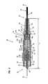
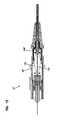
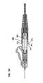
- FIG. 1is a perspective, exploded view of a fiber optic connector in accordance with the principles of the present disclosure
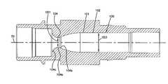
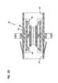
- FIG. 2is a cross-sectional view that longitudinally bisects the fiber optic connector of FIG. 1 ;
- FIG. 3is a perspective view of a rear housing of the fiber optic connector of FIG. 1 ;
- FIG. 4is a cross-sectional view that longitudinally bisects the rear housing of FIG. 3 ;
- FIG. 5is a perspective view showing a first end of a first insertion cap that can be used with the fiber optic connector of FIG. 1 ;
- FIG. 6is a perspective view showing a second end of the insertion cap of FIG. 5 ;
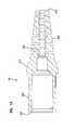
- FIG. 7is a cross-sectional view that longitudinally bisects the insertion cap of FIGS. 5 and 6 .
- FIG. 8is a perspective view showing a first end of a second insertion cap that can be used with the fiber optic connector of FIG. 1 ;
- FIG. 9is a perspective view showing a second end of the insertion cap of FIG. 8 ;
- FIG. 10is a cross-sectional view that bisects the insertion cap of FIGS. 8 and 9 .
- FIG. 11is a perspective view showing a first end of a strain relief boot of the fiber optic connector of FIG. 1 ;
- FIG. 12is a perspective view showing a second end of the strain relief boot of FIG. 11 ;
- FIG. 13is a cross-sectional view that longitudinally bisects the strain relief boot of FIGS. 11 and 12 .
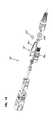
- FIG. 14is an exploded, perspective view of a second fiber optic connector in accordance with the principles of the present disclosure.
- FIG. 15is a cross-sectional view that longitudinally bisects the fiber optic connector of FIG. 14 ;
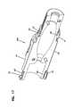
- FIG. 16is a perspective view showing a first side of a half-piece of a rear housing of the fiber optic connector of FIG. 14 ;
- FIG. 17is a perspective view showing a second side of the half-piece of FIG. 16 .
- FIG. 18is side view showing the second side of the half-piece of FIGS. 16 and 17 ;
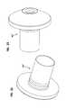
- FIG. 19is a perspective view showing a first end of a first insertion cap that can be used with the fiber optic connector of FIG. 14 ;
- FIG. 20is a perspective view showing a second end of the insertion cap of FIG. 19 ;
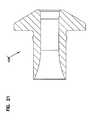
- FIG. 21is a cross-sectional view that longitudinally bisects the insertion cap of FIGS. 19 and 20 ;
- FIG. 22is a perspective view showing a first end of a second insertion cap that can be used with the fiber optic connection of FIG. 14 ;
- FIG. 23is a perspective view showing a second end of the insertion cap of FIG. 22 ;
- FIG. 24is a cross-sectional view that longitudinally bisects the insertion cap of FIGS. 22 and 23 ;
- FIG. 25is a cross-sectional view that longitudinally bisects a prior art fiber optic adapter
- FIG. 26is a cross-sectional view taken along section line 26 - 26 of FIG. 2 ;
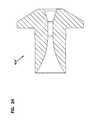
- FIG. 27is a top view of a prior art LC style fiber optic connector
- FIG. 28is a cross-sectional view that longitudinally bisects the fiber optic connector of FIG. 27 ;
- FIG. 29is a perspective, exploded view of a third fiber optic connector having features with inventive aspects in accordance with the principles of the present disclosure.
- FIG. 30is a partially assembled perspective view of the fiber optic connector of FIG. 29 ;
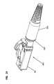
- FIG. 31is a fully assembled perspective view of the fiber optic connector of FIG. 29 ;
- FIG. 32is a top view of the fiber optic connector of FIG. 29 ;
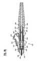
- FIG. 33is a cross-sectional view that longitudinally bisects the fiber optic connector of FIG. 29 ;
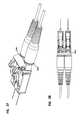
- FIG. 34illustrates a perspective view of two of the fiber optic connectors of FIG. 29 coupled to a duplex LC fiber optic adapter
- FIG. 35is a side view of the fiber optic connectors coupled to a duplex LC fiber optic adapter of FIG. 34 ;
- FIG. 36is a top view of the fiber optic connectors coupled to a duplex LC fiber optic adapter of FIG. 34 ;
- FIG. 37illustrates a perspective view of two of the fiber optic connectors of FIG. 29 coupled together by a clip to form a duplex fiber optic connector
- FIG. 38is a top view of the duplex fiber optic connector of FIG. 37 ;
- FIG. 39is a perspective view of a front housing of the fiber optic connector of FIG. 29 ;
- FIG. 40is a side view of the front housing of the fiber optic connector of FIG. 39 , with a portion of the front housing broken-away to illustrate the internal configuration thereof;
- FIG. 41is a perspective view of a rear housing of the fiber optic connector of FIG. 29 ;
- FIG. 42is a cross-sectional view that longitudinally bisects the rear housing of FIG. 41 ;
- FIG. 43is a cross-sectional view that longitudinally bisects the insertion cap of the fiber optic connector shown in FIG. 29 ;
- FIG. 44is a perspective view of a strain relief boot of the fiber optic connector of FIG. 29 ;
- FIG. 45is a cross-sectional view that longitudinally bisects the strain relief boot of FIG. 41 ;
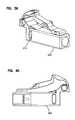
- FIG. 46is a perspective, exploded view of a fourth fiber optic connector having features with inventive aspects in accordance with the principles of the present disclosure.
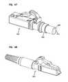
- FIG. 47is a partially assembled perspective view of the fiber optic connector of FIG. 46 ;
- FIG. 48is a fully assembled perspective view of the fiber optic connector of FIG. 46 ;
- FIG. 49is a top view of the fiber optic connector of FIG. 46 ;
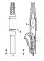
- FIG. 50is a cross-sectional view that longitudinally bisects the fiber optic connector of FIG. 46 ;
- FIG. 51is a perspective view of a rear housing of the fiber optic connector of FIG. 46 ;
- FIG. 52is a front view of the rear housing of FIG. 51 ;
- FIG. 53is a cross-sectional view taken along line 53 - 53 of FIG. 52 ;
- FIG. 54is a cross-sectional view taken along line 54 - 54 of FIG. 53 ;
- FIG. 55is a cross-sectional view taken along line 55 - 55 of FIG. 54 ;
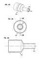
- FIG. 56is a perspective view of an insertion cap that can be used with the fiber optic connector of FIG. 46 ;
- FIG. 57is cross-sectional view that bisects the insertion cap of FIG. 56 ;
- FIG. 58is a cross-sectional view taken along line 58 - 58 of FIG. 57 ;
- FIG. 59is a cross-sectional view taken along line 59 - 59 of FIG. 57 ;
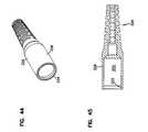
- FIG. 60is a rear perspective view of an example embodiment of a crimp sleeve that might be used to anchor the optical fiber to the connector housing of a fiber optic connector;
- FIG. 61is a rear view of the crimp sleeve of FIG. 60 ;
- FIG. 62is a cross-sectional view taken along lines 62 - 62 of FIG. 61 ;
- FIG. 63is a rear perspective view of another example embodiment of a crimp sleeve that might be used to anchor the optical fiber to the connector housing of a fiber optic connector;
- FIG. 64is a rear view of the crimp sleeve of FIG. 63 ;
- FIG. 65is a cross-sectional view taken along lines 65 - 65 of FIG. 61 ;
- FIGS. 1 and 2illustrate a first fiber optic connector 20 in accordance with the principles of the present disclosure.
- the fiber optic connector 20has a total length L 1 that extends from a distal end 22 of the fiber optic connector 20 to a proximal end 24 of the fiber optic connector 20 .
- the fiber optic connector 20includes a ferrule assembly 26 that mounts adjacent the distal end 22 of the fiber optic connector 20 .
- the ferrule assemblyincludes a ferrule 28 , a hub 30 and a spring 31 .
- the ferrule assembly 26mounts at least partially within a connector housing 32 including a distal housing portion 34 that interconnects with a proximal housing portion 36 .
- the distal housing portion 34snaps over ribs 37 provided on the proximal housing portion 36 to interlock the two housing portions together.
- the fiber optic connector 20also includes a release sleeve 38 that slidably mounts over the connector housing 32 .
- the fiber optic connector 20further includes an insertion cap 40 A that mounts inside a proximal end 42 of the proximal housing portion 36 and a crimp sleeve 44 that mounts around the exterior of the proximal end 42 of the proximal housing portion 36 .
- the proximal end 24 of the fiber optic connector 20is configured to receive, anchor and provide strain relief/bend radius protection to a fiber optic cable 46 .
- the fiber optic cable 46includes a jacket 48 surrounding at least one optical fiber 50 .
- the fiber optic cable 46also includes a strength layer 52 formed by a plurality of strength members (e.g., reinforcing fibers such as aramid yarn/Kevlar) positioned between the optical fiber 50 and the jacket 48 .
- a distal end portion of the strength layer 52is crimped between the crimp sleeve 44 and the exterior surface of the proximal end 42 of the proximal housing portion 36 so as to anchor the strength layer 52 to the connector housing 32 .
- the optical fiber 50is routed through the total length L 1 of the fiber optic connector 20 and includes a distal portion 54 secured within the ferrule 28 .
- the fiber optic connector 20further includes a strain relief boot 56 mounted at the proximal end 24 of the fiber optic connector 20 for providing strain relief and bend radius protection to the optical fiber 50 .
- FIG. 25shows an example fiber optic adapter 58 that can be used to couple two of the fiber optic connectors 20 together.
- the fiber optic adapter 58includes an adapter housing 59 defining opposite, coaxially aligned ports 60 , 62 for receiving two of the fiber optic connectors desired to be coupled together.
- the fiber optic adapter 58also includes an alignment sleeve 64 for receiving and aligning the ferrules 28 of the fiber optic connectors desired to be connected together.
- the fiber optic adapter 58further includes latches 66 for mechanically retaining the fiber optic connectors 20 within their respective ports 60 , 62 .
- the latches 66can be configured to engage shoulders 68 provided on the distal housing portions 34 of the fiber optic connectors 20 being coupled together. Further details regarding the fiber optic adapter 58 can be found in U.S. Pat. No. 5,317,633, which is hereby incorporated by reference in its entirety.
- the release sleeve 38is shown as a conventional SC release sleeve.
- the release sleeve 38is free to slide back-and-forth in distal and proximal directions relative to the connector housing 32 along a central longitudinal axis 70 of the fiber optic connector 20 .
- the keying rail 72 provided on the release sleeve 38ensures that the fiber optic connector 20 is oriented at the appropriate rotational orientation relative to the fiber optic adapter 58 .
- the latches 66snap into a latching position in which the latches engage the shoulders 68 of the connector housing 32 to prevent the fiber optic connector 20 from being proximally withdrawn from the port 60 , 62 .
- the release sleeve 38is provided to allow the fiber optic connector 20 to be selectively withdrawn from its respective port 60 , 62 .
- ramps 74 of the release sleevedisengage the latches 66 of the fiber optic adapter 58 from the shoulders 68 of the fiber optic connector 20 thereby allowing the fiber optic connector 20 to be proximally withdrawn from its respective port 60 , 62 .
- the ferrule 28 of the ferrule assembly 26includes a distal end 76 and a proximal end 78 .
- the distal end 76projects distally outwardly beyond a distal end of the connector housing 32 and the proximal end 78 is secured within the ferrule hub 30 .
- the ferrule hub 30 and the spring 31are captured between the distal housing portion 34 and the proximal housing portion 36 of the connector housing 32 .
- the spring 31is configured to bias the ferrule 28 in a distal direction relative to the connector housing 32 .
- the jacket 48 of the fiber optic cable 46preferably has a relatively small outer diameter D 1 .
- the outer diameter D 1can be less than 2 millimeters, or less than 1.5 millimeters, less than equal to about 1.2 millimeters.
- the optical fiber 50 within the jacket 48can include a core 90 , a cladding layer 92 surrounding the core and one or more coating layers 94 surrounding the cladding layer 92 .
- the core 90can have an outer diameter of about 10 microns
- the cladding layer 92can have an outer diameter of about 125 microns
- the one or more coating layers 94can have an outer diameter in the range of about 240 to 260 microns.
- the strength layer 52provides tensile reinforcement to the cable 46 .
- the strength layer 52relatively closely surrounds the coating layer 94 of the optical fiber 50 .
- the strength layer 52also functions as a separator for separating the optical fiber 50 from the outer jacket 48 .
- no buffer layer or buffer tubeis provided between the coating layer 94 of the optical fiber 50 and the strength layer 52 . Further details regarding the fiber optic cable 46 can be found in U.S. Pat. No. 8,548,293, which is hereby incorporated by reference in its entirety.
- the optical fiber 50extends through the total length L 1 of the fiber optic connector 20 .
- the optical fiber 50extends through the strain relief boot 56 , the insertion cap 40 A, the connector housing 32 and the ferrule 28 .
- a portion of the optical fiber 50 extending proximally from the ferrule 28 through the fiber optic connector 20 to the jacketed portion of the fiber optic cable 46includes only the core 90 , the cladding layer 92 and the one or more coating layers 94 .
- the portion of the optical fiber 50 extending through the ferrule 28typically only includes the core 90 and the cladding layer 92 .
- a distal most end face of the optical fiber 50is preferably polished as is conventionally known in the art.
- the insertion cap 40 A(see FIGS. 5-7 ) is mounted within the proximal end 42 of the proximal housing portion 36 of the connector housing 32 .
- the insertion cap 40 Ahas an inner diameter D 2 sized to correspond with the outer diameter of the coating layer 94 .
- a protective layersuch as a 900 micron tube (e.g., a 900 micron furcation tube).
- the insertion cap 40 Acan be replaced with an insertion cap 40 B (see FIGS. 8-10 ) having an inner diameter D 3 that is larger than the inner diameter D 2 .
- inner diameter D 3can correspond to the outer diameter of protective buffer tube provided about the coating layer 94 of the optical fiber 50 within the connector housing 32 .
- the fiber optic connector 20is a pull-proof connector in which the strength layer 52 of the fiber optic cable 46 is anchored to the connector housing 32 thereby preventing tensile loads from being transferred to the ferrule assembly 26 . Because of this configuration, movement of the ferrule 28 in a proximal direction relative to the connector housing 32 causes the optical fiber 50 to be forced/displaced in a proximal direction relative to the connector housing 32 and the jacket 48 of the fiber optic cable 46 . In the depicted embodiment, the ferrule 28 has a maximum axial displacement AD in the proximal direction during the connection process. The axial displacement AD creates an excess fiber length having a length equal to the length of the axial displacement AD. In certain embodiments, the maximum axial displacement AD can be 0.035 inches.
- the connector 20is itself preferably configured to take-up the excess fiber length corresponding to the axial displacement.
- the fiber optic connector 20includes features that encourage a controlled, predictable and repeatable macrobend of the optical fiber 50 within the connector housing 32 when the ferrule 28 is forced in a proximal direction relative to the connector housing 32 .
- the fiber optic connector 20itself accommodates the acceptable macrobending of the optical fiber 50 such that the optical fiber 50 does not need to slide within the jacket 48 of the fiber optic cable 46 and does not require the optical fiber 52 to macro or microbend within the jacket 48 of the fiber optic cable 46 when the ferrule 28 is forced in a proximal direction relative to the connector housing 32 .
- the fiber optic connector 20is preferably designed to take-up the optical fiber length corresponding to the axial displacement AD.
- the connector housing 32includes a fiber take-up region 100 that extends generally from a proximal end of the spring 31 to the proximal end 42 of the proximal housing portion 36 .
- the fiber take-up region 100includes a passage 101 that extends along the axis 70 .
- the passage 101has an intermediate section 102 , a distal section 104 and a proximal section 106 .
- the intermediate section 102has an enlarged transverse cross-sectional area as compared to the transverse cross-sectional areas of the distal and proximal sections 104 , 106 .
- the transverse cross-sectional areasare taken along planes perpendicular to the longitudinal axis 70 of the connector 20 .
- the distal section 104 and the intermediate section 102are defined by the proximal housing portion 36 (see FIG. 4 ).
- the distal section 104 of the passage 101has a necked configuration with a neck portion 104 a positioned between transition portions 104 b and 104 c .
- the neck portion 104 adefines a minimum cross-dimension CD 1 (e.g., an outer diameter) and minimum transverse cross-sectional area of the distal section 104 .
- the transition portion 104 bprovides a gradual reduction in transverse cross-sectional area (i.e., a funnel or taper toward the longitudinal axis 70 ) as the transition portion 104 b extends from the intermediate section 102 of the passage 101 toward the neck portion 104 a .
- the transition portion 104 cprovides a gradual increase in transverse cross-sectional area (i.e., a funnel or taper away from the longitudinal axis 70 ) as the transition portion 104 c extends from the neck portion 104 a toward the spring 31 .
- the proximal section 106 of the passage 101is defined by the inside of the insertion cap 40 A or the insertion cap 40 B (depending on which one is selected). For ease of explanation, the description herein will primarily refer to the insertion cap 40 A (see FIGS. 5-7 ).
- a minimum cross-dimension CD 2e.g., an outer diameter
- the proximal section 106includes a transition 106 a that provides a reduction in transverse cross-sectional area as the transition 106 a extends in a proximal direction from the intermediate section 102 of the passage 101 toward the minimum cross-dimension CD 2 .
- a chamfer 109 at the proximal end of the insertion cap 40 Aprovides an increase in transverse cross-sectional area as the chamfer 109 extends proximally from the minimum cross-dimension C 2 .
- the chamfer 109can assist in providing bend radius protection with respect to the fiber passing through the insertion cap 40 A. It will be appreciated that by using the insertion cap 40 B, the minimum diameter provided by the insertion cap can be enlarged so as to accommodate a productive buffer tube covering the optical fiber 50 within the passage 101 .
- the minimum cross-dimension CD 1is greater than the minimum cross-dimension CD 2 . In other embodiments, the minimum cross-dimension CD 1 is at least twice as large as the minimum cross-dimension CD 2 . In other embodiments, the minimum cross-dimension CD 1 is generally equal to the minimum cross-dimension CD 2 . In still further embodiments, a maximum cross-dimension CD 3 of the passage 101 is at least 1.5 times or 2 times as large as the minimum cross-dimension CD 1 . In still other embodiments, the maximum cross-dimension CD 3 of the passage 101 is at least 2, 3 or 4 times as large as the minimum cross-dimension CD 2 .
- the length and transverse cross-sectional dimensions of the fiber take-up region 100are selected to accommodate the excess length of fiber corresponding to the axial displacement distance AD.
- the configuration of the fiber take-up region 100causes the optical fiber 50 to move from a generally straight path SP along the axis 70 to a path that follows generally along a single macrobend 120 (shown at FIG. 2 ) that extends along the surface of the fiber take-up region 100 from the distal section 104 through the intermediate section 102 to the proximal section 106 .
- the increase in length between the straight path and the curved pathequals the axial displacement distance AD.
- the transitions 104 b , 106 a provided at the proximal and distal sections 104 , 106 of the passage 101help to encourage the fiber to form the single microbend in a predictable, repeatable manner as the ferrule 28 is forced in a proximal direction relative to the connector housing 32 during a connection process.
- the fiber take-up regionis configured to take up at least 0.015 inches, or at least 0.025 inches or at least 0.035 inches of excess fiber length.
- the transition 104 balso facilitates assembly of the fiber optic connector 20 . Specifically, during assembly, the optical fiber 50 is inserted in a distal direction through the proximal end 42 of the connector housing 32 and is directed through the length of the connector housing into the ferrule 28 . The transition 104 b assists in guiding the fiber 50 into the ferrule 28 during the fiber insertion process.
- the insertion cap 40 Aincludes a sleeve portion 110 having a cylindrical outer surface that fits inside the proximal end 42 of the connector housing 32 .
- the insertion cap 40 Aalso includes a flange 112 at a proximal end of the sleeve portion 110 .
- the flange 112projects radially outwardly from the cylindrical outer surface of the sleeve portion 110 and forms a proximal end of the insertion cap 40 A.
- the flange 112abuts against the proximal end 42 of the connector housing 32 when the insertion cap 40 A is inserted therein.
- the inside of the insertion cap 40 Adefines the proximal section 106 of the passage 101 which extends in a proximal to distal direction through the insertion cap 40 A.
- the insertion cap 40 Bhas a similar configuration as the insertion cap 40 A, except the minimum inner cross-dimension CD 2 (e.g., inner diameter) of the insertion cap 40 B is larger than the minimum cross-dimension CD 2 of the insertion cap 40 A so as to better accommodate a protective tube covering the coated fiber 50 within the connector housing 32 .
- the use of the insertion cap 40 A or the insertion cap 40 Ballows the proximal end 42 of the connector housing 32 to have a relatively large open transverse cross-sectional area which corresponds to the maximum cross-dimension CD 3 of the passage 101 .
- This large transverse cross-sectional areais advantageous because it facilitates delivering potting material (e.g., and adhesive material such as epoxy) to the back side of the ferrule 28 during assembly for potting the fiber 50 within the ferrule 28 .
- potting materiale.g., and adhesive material such as epoxy
- a needlecan be used to deliver potting material to the ferrule 28 .
- the large cross-sectional areaprovides better access for allowing a needle to be inserted through the proximal end of the connector housing 32 to accurately injecting potting material into the ferrule 28 .
- the crimp sleeve 44 of the fiber optic connector 20includes a sleeve portion 140 and a stub portion 142 that projects proximately outwardly from a proximal end of the sleeve portion 140 .
- a radial in-step 141is provided between the sleeve portion 140 and the stub portion 142 such that the sleeve portion 140 has a larger diameter than the stub portion 142 .
- a passageextends axially throughout the length of the crimp sleeve 44 . The passage has a smaller diameter through the stub portion 142 and a larger diameter through the sleeve portion 140 .
- the sleeve portion 140is crimped about the exterior surface of the connector housing 32 adjacent the proximal end 42 of the connector housing 32 (see FIG. 2 ).
- the exterior surface of the connector housing 32can be textured (e.g., knurled, ridged, provided with small projections, etc.) to assist in retaining the crimp on the housing 32 .
- a distal portion of the strength layer 52 of the fiber optic cable 46is crimped between the sleeve portion 140 and the exterior surface of the connector housing 32 such that the strength layer 52 of the cable 46 is anchored relative to the connector housing 32 .
- the sleeve portion 140 of the crimp sleevemay include an annular rib 143 on an exterior surface thereof.
- the annular rib 143may provide additional material for the crimp sleeve 44 at spots or regions that will to tend to deform when the crimp sleeve 44 is crimped at the sleeve portion 140 .
- the stub portion 142fits within a pocket 144 provided within the strain relief boot 56 .
- the stub portion 142coaxially aligns with the central longitudinal axis 70 of the fiber optic connector 20 .
- the insertion cap 40 Ais captured between the proximal end 42 of the connector housing 32 and the crimp sleeve 44 . In this way, the crimp sleeve 44 assists in retaining the insertion cap 40 A in the proximal end 42 of the connector housing 32 .
- the insertion cap 40 Acan also be held within the connector housing 22 by an adhesive material such as epoxy.
- the optical fiber 50can be anchored relative to the connector housing 32 adjacent the proximal end 42 thereof.
- the location where the optical fiber 52 itself is crimped to the connector housing 32may be called the fiber anchor location 51 (see FIG. 2 ).
- Anchoring the optical fiber 50 relative to the proximal end 42 of the connector housing 32can isolate the movable ferrule assembly 26 from the rest of the fiber optic cable 46 that is not pinched or crimped to the connector housing 32 . This is advantageous because, if the optical fiber 50 were not anchored to the connector housing 32 , in certain instances, the optical fiber 50 may slide within the outer jacket 48 , interfering with the predictability and the repeatability of the macrobending that takes place within the fiber take-up region 100 when the ferrule 28 is forced in a proximal direction.
- the fiber 50might tend to migrate toward the inner diameter side of the cable within the cable and might move a different distance than the outer jacket 48 itself. If the fiber 50 were to slide within the outer jacket 48 toward the ferrule assembly 26 , that would create extra fiber within the connector, interfering with the predictability of the acceptable macrobending that takes place within the fiber take-up region 100 .
- the outer jacket 48 of the cable 46might stretch inelastically and the optical fiber 50 could slidably move within the jacket, relative to the jacket, causing a pulling force on the ferrule assembly 26 .
- the movable ferrule assembly 26is isolated from the rest of the fiber optic cable 46 that is not crimped to the connector housing 32 . As such, axial load is not transferred in either direction across the anchor location.
- the anchorrestricts/prevents relative movement between the optical fiber and the jacket at the fiber anchor location. In this way, the portion of the fiber within the connector and the portion of the fiber within the main length of the cable are mechanically isolated from one another.
- the connector of the present disclosurethus, can operate as designed and utilize the fiber take-up region 100 to provide for a predictable and a repeatable macrobend when the ferrule is moved in a proximal direction relative to the connector housing 32 .
- FIGS. 60-65illustrate two different embodiments of crimp sleeves 544 , 644 that include annular ribs on an exterior surface of the stub portions thereof.
- the crimp sleeves 544 and 644 shown in FIGS. 60-65may provide for additional material for the stub portions of the crimp sleeve at spots or regions that might tend to deform when the crimp sleeve is crimped at the stub portion.
- the stub portion 542 of the sleeve 544includes a first annular rib 543 at a proximal end 547 thereof and a second annular rib 545 at an intermediate location between the proximal end 547 and the radial in-step 541 of the crimp sleeve 544 .
- the stub portion 642 of the sleeve 644includes a single, wider annular rib 643 at a proximal end 647 thereof.
- the fiber anchor locationis defined as being at a location that is not at a splice location where two segments of optical fiber are spliced together.
- the optical fiberis directly terminated in the connector and the connector is not a splice-on connector.
- the ferrule assembly 26is first loaded into the distal housing portion 34 of the connector housing 32 .
- the proximal to housing portion 36is connected to the distal housing 34 (e.g., by a snap fit connection) such that the ferrule hub 30 and the spring 31 are captured within the connector housing 32 at a location between the distal housing portion 34 and the proximal housing portion 46 .
- an epoxy needleis inserted through the proximal end 42 of the proximal housing portion 36 and is used to inject epoxy into the fiber passage defined through the ferrule 28 .
- the epoxy needleis removed and the insertion cap 40 A or the insertion cap 40 B is inserted into the proximal end 42 of the connector housing 32 . Thereafter, the strain relief boot 56 and the crimp sleeve 44 are inserted over the fiber optic cable 46 and a distal end portion of the cable is prepared.
- the jacket 48is stripped from the distal end portion of the optical fiber.
- the coating layers 94are stripped from the distalmost portion of the optical fiber 50 intended to be inserted through the passage defined by the ferrule 28 .
- the strength layer 52is trimmed to a desired length.
- the crimp sleeve 44is slid distally over the proximal end 42 of the connector housing 32 and used to crimp the distal end of the strength layer 52 about the exterior surface of the connector housing 32 adjacent to the proximal end 42 .
- the strain relief boot 56is then slid distally over the crimp sleeve 44 and proximal end 42 of the housing 32 .
- the release sleeve 38is inserted over the distal end 22 of the fiber optic connector 20 and snapped into place over the connector housing 32 .
- the strain relief boot 56 of the fiber optic connector 20includes a distal end 200 and an opposite proximal end 202 .
- the strain relief bootdefines an inner passage 204 that extends through the boot from the proximal end 202 to the distal end 200 .
- the inner passage 204aligns with the central longitudinal axis 70 of the fiber optic connector 20 .
- the boot 56includes a connection portion 206 positioned adjacent the distal end 200 and a tapered, strain relief portion 208 positioned adjacent the proximal end 202 .
- the connection portion 206has a larger cross-dimension than a corresponding cross-dimension of the tapered, strain relief portion 208 .
- a transition portion 210is positioned between the to connection portion 206 and the tapered, strain relief portion 208 .
- An outer surface of the transition portionprovides a gradual increase in cross-dimension as the outer surface extends from the tapered, strain relief portion 208 to the connection portion 206 .
- the outer surface of the transition portion 210can be pushed to facilitate inserting the connection portion 206 over the proximal end 42 of the connector housing 32 during assembly of the fiber optic connector 20 . Further details about the boot 56 are provided in U.S. Provisional Patent Application Ser. No. 61/452,935, which is entitled STRAIN RELIEF BOOT FOR A FIBER OPTIC CONNECTOR, and which has been filed on a date concurrent with the filing of the present application.
- FIGS. 14-24show various parts of another fiber optic connector 20 ′ in accordance with the principles of the present disclosure.
- the connector 20 ′has been modified with respect to the connector 20 so as to include a proximal housing portion 36 ′, an insertion cap 40 A′ and an insertion cap 40 B′ which are all made of molded plastic.
- the other components of the connector 20 ′are the same as the connector 20 .
- FIG. 14shows various parts of another fiber optic connector 20 ′ in accordance with the principles of the present disclosure.
- the connector 20 ′has been modified with respect to the connector 20 so as to include a proximal housing portion 36 ′, an insertion cap 40 A′ and an insertion cap 40 B′ which are all made of molded plastic.
- the other components of the connector 20 ′are the same as the connector 20 .
- the proximal housing portion 36 ′is formed by two molded half-pieces 36 a that mate together to form the proximal housing portion 36 ′.
- the half-pieces 36 acan be bonded together with an adhesive or held together mechanically by one or more fasteners such as crimps. According to certain embodiments, the half-pieces 36 a may be held together by a snap-fit interlock. According to the example embodiment depicted in FIGS.
- each half piece 36 aincludes flexible cantilever arms 41 on one side 43 of the half-piece 36 a and notches 45 on the radially opposite side 47 of the half-piece 36 a (see FIGS. 16-17 ).
- Each cantilever arm 41defines a tab 49 at the end of the arm 41 that is configured to snap over shoulders 51 defined at the notches 45 when two half-pieces 36 a are interlocked together.
- the cantilever arms 41 and the notches 45 of one half-piece 36 aare provided on opposite sides with respect to the arms 41 and notches 45 , respectively, of the other half-piece 36 a . As such, when the two half-pieces 36 a are brought together for a snap-fit interlock, the cantilever arms 41 of one half-piece 36 a align with the notches 45 of the opposing half-piece 36 a and vice versa.
- the molding process used to manufacture the proximal housing portion 36 ′allows the interior of the proximal housing portion 36 ′ to be provided with a continuous curve 150 that extends along the length of the take-up region of connector 20 ′.
- the insertion caps 40 A′ and 40 B′are similar to the insertion caps 40 A, 40 B except the parts are molded plastic parts with the inner diameter transitions at the proximal and distal ends of the caps have a more curved profile.
- FIGS. 27 and 28illustrate a prior art fiber optic connector 220 in the form of a conventional LC connector.
- the conventional LC connector 220includes a connector housing 222 defining a distal housing portion 224 and a proximal housing portion 226 .
- the LC connector 220includes a ferrule assembly 228 defined by a ferrule 230 , a hub 232 , and a spring 234 .
- a proximal end 236 of the ferrule 230is secured within the ferrule hub 232 .
- the ferrule hub 232 and the spring 234are captured between the distal housing portion 224 and the proximal housing portion 226 of the connector housing 222 and a distal end 238 of the ferrule 230 projects distally outwardly beyond a distal end 240 of the connector housing 222 .
- the spring 234is configured to bias the ferrule 230 in a distal direction relative to the connector housing 222 .
- the distal housing portion 224may be formed from a molded plastic.
- the distal housing portion 224defines a latch 242 extending from a top wall 244 of the distal housing portion 224 toward the proximal end 246 , the latch 242 extending at an acute angle with respect to the top wall 244 of the distal housing portion 224 .
- the distal housing portion 224also includes a latch trigger 248 that extends from the proximal end 246 of the distal housing portion 224 toward the distal end 240 .
- the latch trigger 248also extends at an acute angle with respect to the top wall 244 .
- the latch trigger 248is configured to come into contact with the latch 242 for flexibly moving the latch 242 downwardly.
- the latch 242functions to lock the fiber optic connector 220 in place within the adapter 250 .
- the fiber optic connector 220may be removed from the adapter 250 by depressing the latch trigger 248 , which causes the latch 242 to be pressed in a downward direction, freeing catch portions 252 of the latch 242 from the fiber optic adapter 250 .
- the region of the distal housing portion 224 from where the latch trigger 248 extendsdefines a pin hole 254 .
- the pin hole 254is configured to receive a pin for forming a duplex LC connector by coupling two simplex connectors 220 in a side-by-side orientation.
- a strain relief boot 256is slid over a proximal end 258 of the proximal housing portion 226 and snaps over a boot flange 260 to retain the boot 256 with respect to the connector housing 222 .
- the proximal end 258 of the proximal housing portion 226defines a crimp region 262 for crimping a fiber optic cable's strength layer to the proximal housing portion 226 , normally with the use of a crimp sleeve (not shown).
- the exterior surface 264 of the proximal housing portion 226 defining the crimp region 262can be textured (e.g., knurled, ridged, provided with small projections, etc.) to assist in retaining the crimp on the housing 222 .
- the passage 266 defined by the proximal housing portion 226 that extends along the longitudinal axis of the connector 220defines a generally uniform inner diameter DLC similar in size to the diameter of the portion of the optical fiber that includes the core, the cladding layer and the one or more coating layers.
- the proximal housing portion 226 of a conventional LC connector 220does not include a fiber take-up region to prevent signal degradation related to microbending caused by the axial displacement of the optical fiber in the proximal direction.
- FIGS. 29-45illustrate various parts of a third fiber optic connector 300 in accordance with the principles of the present disclosure.
- the connector 300includes inventive features similar to those shown and described for the SC type connectors 20 , 20 ′ of FIGS. 1-26 , however, is provided in an LC connector footprint.
- the fiber optic connector 300includes a connector housing 301 including a distal housing portion 302 and a proximal housing portion 304 .
- the distal housing portion 302is similar in configuration to that of a conventional LC connector and includes a ferrule assembly 306 defined by a ferrule 308 , a hub 310 , and a spring 312 mounted therein.
- the ferrule hub 310 and the spring 312are captured within the distal housing portion 302 by the proximal housing portion 304 of the connector housing 301 .
- the distal housing portion 302defines slots 314 that are configured to receive ribs 316 formed at a distal end 318 of the proximal housing portion 304 for snap-fitting the two housing portions 302 , 304 together.
- An insertion cap 320 having features similar to insertion caps 40 A and 40 A′is inserted into a proximal end 322 of the proximal housing portion 304 .
- an alternative embodiment of an insertion cap having a larger inner diameter for accommodating a protective tubingcan also be used.
- a crimp sleeve 324is inserted over the proximal end 322 of the proximal housing portion 304 and captures the insertion cap 320 thereagainst. The crimp sleeve 324 is used to crimp a fiber optic cable in a manner similar to that described above for the SC style connectors 20 , 20 ′.
- a strain relief boot 326is mounted over the proximal end 322 of the proximal housing portion 304 .
- the strain relief boot 326includes a connection portion 328 defining a generally circular inner passage 330 (see FIGS. 44 and 45 ).
- An annular inner lip 332 defined at a distal end 334 of the strain relief boot 326mounts over a generally round boot flange 336 defined on the outer surface 338 of the proximal housing portion 304 .
- the distal end 334 of the strain relief boot 326abuts against a stop ring 340 .
- the stop ring 340defines a conical configuration 342 along the longitudinal direction of the connector 300 , the ring 340 tapering down as it extends from a proximal end 344 toward a distal end 346 .
- FIGS. 37 and 38illustrate two of the fiber optic connectors 300 mounted together using a duplex clip 348 .
- FIGS. 34-36illustrate two of the fiber optic connectors 300 mounted in a standard duplex LC adapter 250 in a side by side configuration.
- the proximal housing portion 304 and the insertion cap 320 of the connector 300are configured to provide a fiber take-up spacing 350 for allowing macrobending of the optical fiber within the connector housing 301 , in a similar fashion to that described above for the SC style connectors 20 , 20 ′.
- the proximal housing portion 304 and the insertion cap 320are depicted as machined metal parts.
- FIGS. 46-59illustrate various parts of a fourth embodiment of a fiber optic connector 400 in accordance with the principles of the present disclosure.
- the connector 400has been modified with respect to the connector 300 so as to include a proximal housing portion 402 and an insertion cap 404 which are made of molded plastic.
- the proximal housing portion 402 of the connector housing 406defines an obround passage 408 that transitions to a generally circular passage 410 as it extends from a proximal end 412 of the proximal housing portion 402 to the distal end 414 thereof.
- the passagedefines an obround configuration 408 from the proximal end 412 until it reaches the transition portion 416 coming before the neck portion′ 418 .
- the obround portion 408 of the passageis provided to increase the predictability of the bending of the fiber as the fiber is exposed to axial displacement within the connector 400 and control the direction of the bend.
- the obround portion 408 of the passagedefines a larger cross-dimension CDO along a first direction DO 1 (taken along lines 55 - 55 of FIG. 54 ) than a second direction DO 2 (taken along lines 53 - 53 of FIG. 52 ).
- the size of the opening 420 at the proximal end 412 of the proximal housing portion 402is increased relative to the annular circular opening 354 of the connector 300 shown in FIGS. 29-45 when that opening 420 is measured along the longer cross dimension CDO of the obround passage 408 .
- the sidewall 422 defined along the longer cross dimension CDO of the obround passage 408is able to be decreased relative to a uniform sidewall 356 that is provided about the circular opening 354 of the connector 300 .
- the insertion cap 404 of the connector 400defines a stub portion 426 having an exterior obround configuration 428 to match that of the proximal end 412 of the proximal housing portion 402 .
- the insertion cap 404also defines an internal passage 430 that transitions from a generally circular opening 432 to an obround configuration 434 as the passage 430 extends from the proximal end 436 to the distal end 438 of the insertion cap 404 .
- the obround portion 434 of the passage 430cooperates with the obround portion 408 of the internal passage of the proximal housing portion 402 in controlling the direction of the fiber bend.
Landscapes
- Physics & Mathematics (AREA)
- General Physics & Mathematics (AREA)
- Optics & Photonics (AREA)
- Mechanical Coupling Of Light Guides (AREA)
Abstract
Description
Claims (21)
Priority Applications (6)
| Application Number | Priority Date | Filing Date | Title |
|---|---|---|---|
| US15/357,030US9841566B2 (en) | 2011-03-15 | 2016-11-21 | Fiber optic connector |
| US15/837,290US10146011B2 (en) | 2011-03-15 | 2017-12-11 | Fiber optic connector |
| US16/204,672US10495822B2 (en) | 2011-03-15 | 2018-11-29 | Fiber optic connector |
| US16/696,629US10859771B2 (en) | 2011-03-15 | 2019-11-26 | Fiber optic connector |
| US17/110,854US11782224B2 (en) | 2011-03-15 | 2020-12-03 | Fiber optic connector |
| US18/477,750US12405430B2 (en) | 2011-03-15 | 2023-09-29 | Fiber optic connector |
Applications Claiming Priority (6)
| Application Number | Priority Date | Filing Date | Title |
|---|---|---|---|
| US201161452953P | 2011-03-15 | 2011-03-15 | |
| US201161510711P | 2011-07-22 | 2011-07-22 | |
| US13/420,286US8636425B2 (en) | 2011-03-15 | 2012-03-14 | Fiber optic connector |
| US14/154,352US9151904B2 (en) | 2011-03-15 | 2014-01-14 | Fiber optic connector |
| US14/858,900US9500813B2 (en) | 2011-03-15 | 2015-09-18 | Fiber optic connector |
| US15/357,030US9841566B2 (en) | 2011-03-15 | 2016-11-21 | Fiber optic connector |
Related Parent Applications (1)
| Application Number | Title | Priority Date | Filing Date |
|---|---|---|---|
| US14/858,900ContinuationUS9500813B2 (en) | 2011-03-15 | 2015-09-18 | Fiber optic connector |
Related Child Applications (1)
| Application Number | Title | Priority Date | Filing Date |
|---|---|---|---|
| US15/837,290ContinuationUS10146011B2 (en) | 2011-03-15 | 2017-12-11 | Fiber optic connector |
Publications (2)
| Publication Number | Publication Date |
|---|---|
| US20170168245A1 US20170168245A1 (en) | 2017-06-15 |
| US9841566B2true US9841566B2 (en) | 2017-12-12 |
Family
ID=46831353
Family Applications (9)
| Application Number | Title | Priority Date | Filing Date |
|---|---|---|---|
| US13/420,286Expired - Fee RelatedUS8636425B2 (en) | 2011-03-15 | 2012-03-14 | Fiber optic connector |
| US14/154,352ActiveUS9151904B2 (en) | 2011-03-15 | 2014-01-14 | Fiber optic connector |
| US14/858,900Expired - Fee RelatedUS9500813B2 (en) | 2011-03-15 | 2015-09-18 | Fiber optic connector |
| US15/357,030Expired - Fee RelatedUS9841566B2 (en) | 2011-03-15 | 2016-11-21 | Fiber optic connector |
| US15/837,290ActiveUS10146011B2 (en) | 2011-03-15 | 2017-12-11 | Fiber optic connector |
| US16/204,672Expired - Fee RelatedUS10495822B2 (en) | 2011-03-15 | 2018-11-29 | Fiber optic connector |
| US16/696,629ActiveUS10859771B2 (en) | 2011-03-15 | 2019-11-26 | Fiber optic connector |
| US17/110,854Active2032-12-19US11782224B2 (en) | 2011-03-15 | 2020-12-03 | Fiber optic connector |
| US18/477,750ActiveUS12405430B2 (en) | 2011-03-15 | 2023-09-29 | Fiber optic connector |
Family Applications Before (3)
| Application Number | Title | Priority Date | Filing Date |
|---|---|---|---|
| US13/420,286Expired - Fee RelatedUS8636425B2 (en) | 2011-03-15 | 2012-03-14 | Fiber optic connector |
| US14/154,352ActiveUS9151904B2 (en) | 2011-03-15 | 2014-01-14 | Fiber optic connector |
| US14/858,900Expired - Fee RelatedUS9500813B2 (en) | 2011-03-15 | 2015-09-18 | Fiber optic connector |
Family Applications After (5)
| Application Number | Title | Priority Date | Filing Date |
|---|---|---|---|
| US15/837,290ActiveUS10146011B2 (en) | 2011-03-15 | 2017-12-11 | Fiber optic connector |
| US16/204,672Expired - Fee RelatedUS10495822B2 (en) | 2011-03-15 | 2018-11-29 | Fiber optic connector |
| US16/696,629ActiveUS10859771B2 (en) | 2011-03-15 | 2019-11-26 | Fiber optic connector |
| US17/110,854Active2032-12-19US11782224B2 (en) | 2011-03-15 | 2020-12-03 | Fiber optic connector |
| US18/477,750ActiveUS12405430B2 (en) | 2011-03-15 | 2023-09-29 | Fiber optic connector |
Country Status (9)
| Country | Link |
|---|---|
| US (9) | US8636425B2 (en) |
| EP (1) | EP2686724B1 (en) |
| CN (1) | CN103502860B (en) |
| AU (1) | AU2012229131B2 (en) |
| CA (1) | CA2830251C (en) |
| ES (1) | ES2774970T3 (en) |
| MX (1) | MX2013010482A (en) |
| RU (1) | RU2591232C2 (en) |
| WO (1) | WO2012125836A2 (en) |
Cited By (4)
| Publication number | Priority date | Publication date | Assignee | Title |
|---|---|---|---|---|
| WO2020075734A1 (en) | 2018-10-11 | 2020-04-16 | 株式会社フジクラ | Optical fiber cable |
| US11275217B2 (en)* | 2019-06-26 | 2022-03-15 | Senko Advanced Components, Inc. | Field installable fiber optic connector with crimp zones for unjacketed optical fibers |
| US20230168441A1 (en)* | 2021-11-30 | 2023-06-01 | Corning Research & Development Corporation | Unjacketed fiber optic cable assembly, and cable assembly including connector with travel limited ferrule |
| US11686904B2 (en) | 2020-06-18 | 2023-06-27 | Commscope Technologies Llc | Optical fiber connector and cable assembly and optical fiber cable connection system |
Families Citing this family (107)
| Publication number | Priority date | Publication date | Assignee | Title |
|---|---|---|---|---|
| US8989541B2 (en) | 2006-08-01 | 2015-03-24 | Adc Telecommunications, Inc. | Cable and dual inner diameter ferrule device with smooth internal contours and method |
| US7341383B2 (en) | 2006-08-01 | 2008-03-11 | Adc Telecommunications, Inc. | Dual inner diameter ferrule device and method |
| US7534050B2 (en) | 2007-04-13 | 2009-05-19 | Adc Telecommunications, Inc. | Field terminatable fiber optic connector assembly |
| US8702323B2 (en)* | 2011-03-15 | 2014-04-22 | Adc Telecommunications, Inc. | Strain relief boot for a fiber optic connector |
| US8636425B2 (en) | 2011-03-15 | 2014-01-28 | Adc Telecommunications, Inc. | Fiber optic connector |
| RU2603237C2 (en) | 2011-07-22 | 2016-11-27 | Адс Телекоммьюникейшнз, Инк. | Unit of connection of fibre-optic cable with connector having fibre locking means |
| CN102955206B (en)* | 2011-08-29 | 2015-02-04 | 鸿富锦精密工业(深圳)有限公司 | Optical fiber connector |
| US12013577B2 (en) | 2011-10-10 | 2024-06-18 | Commscope Technologies Llc | Cable and dual inner diameter ferrule device with smooth internal contours and method |
| RU2619816C2 (en) | 2012-02-07 | 2017-05-18 | Тайко Электроникс Райхем Бвба | Cable terminal assembly and method for fixing fiber-optic cable to connector |
| US9176285B2 (en) | 2012-05-03 | 2015-11-03 | Adc Telecommunications, Inc. | Fiber optic connector |
| CH706931A1 (en)* | 2012-09-12 | 2014-03-14 | Fischer Connectors Holding Sa | Contact waterproof connector when disconnected. |
| US9310572B2 (en) | 2012-10-18 | 2016-04-12 | Corning Cable Systems Llc | Cable bend relief for fiber optic sub-assemblies and methods of assembling |
| CN104823090B (en)* | 2012-11-30 | 2017-04-05 | 泰科电子公司 | Fiber optic connectors with field-installable outer connector housings |
| WO2014118225A1 (en) | 2013-01-29 | 2014-08-07 | Tyco Electronics Raychem Bvba | Fiber optic connector with fiber end protection |
| WO2014164880A1 (en)* | 2013-03-11 | 2014-10-09 | Adc Telecommunications, Inc. | Fiber optic connector and fiber optic cable assembly with fiber optic cable anchored to boot of fiber optic connector |
| WO2014151443A1 (en) | 2013-03-15 | 2014-09-25 | Adc Telecommunications, Inc. | Ferrules for fiber optic connectors |
| WO2014206976A1 (en) | 2013-06-27 | 2014-12-31 | Tyco Electronics Raychem Bvba | Fiber optic cable anchoring device for use with fiber optic connectors and methods of using the same |
| CA2916720A1 (en) | 2013-07-16 | 2015-04-02 | 3M Innovative Properties Company | Connector for telecommunication enclosures |
| US9977198B2 (en) | 2013-07-16 | 2018-05-22 | 3M Innovative Properties Company | High retention force optical coupling |
| US9618703B2 (en)* | 2013-10-03 | 2017-04-11 | Senko Advanced Components, Inc. | Connector housing for securing an optical cable and methods of use and manufacture thereof |
| US9285550B2 (en) | 2013-10-21 | 2016-03-15 | Commscope Technologies Llc | Fiber optic connector with rotational interlock between connector housing and rear insert |
| CN104849816B (en) | 2014-02-14 | 2017-01-11 | 泰科电子(上海)有限公司 | Optical fiber connector and assembly method therefor |
| CN104849815B (en) | 2014-02-14 | 2017-01-18 | 泰科电子(上海)有限公司 | Optical fiber connector and assembly method therefor |
| CN104034456B (en)* | 2014-04-15 | 2016-04-13 | 南昌大学 | The optical fiber macrobend anamorphoser of adjustable bending radius |
| WO2016004347A1 (en)* | 2014-07-03 | 2016-01-07 | Adc Telecommunications, Inc. | Optical fiber connector for multi-fiber cable |
| CN105445862B (en) | 2014-07-09 | 2018-01-19 | 泰科电子(上海)有限公司 | The joints of optical fibre and its on-site assembly method |
| US9874704B2 (en)* | 2014-08-13 | 2018-01-23 | Finisar Corporation | Ferrule assemblies |
| EP3180644B1 (en) | 2014-08-14 | 2020-02-26 | CommScope Connectivity Belgium BVBA | Fiber optic adapter assembly |
| US10054753B2 (en) | 2014-10-27 | 2018-08-21 | Commscope Technologies Llc | Fiber optic cable with flexible conduit |
| US9551842B2 (en)* | 2015-01-15 | 2017-01-24 | Corning Optical Communications LLC | Fiber optic connector with strain relief assembly |
| US9507101B2 (en)* | 2015-02-03 | 2016-11-29 | SENKO Advanced Components (HK) Ltd. | Optical fiber connector with improved optical fiber cable fixing mechanism |
| US9658409B2 (en) | 2015-03-03 | 2017-05-23 | Senko Advanced Components, Inc. | Optical fiber connector with changeable polarity |
| EP3822676A1 (en) | 2015-04-02 | 2021-05-19 | CommScope Technologies LLC | Fiber optic network architecture using high fiber-count fiber optic connectors |
| US10534139B2 (en)* | 2015-06-23 | 2020-01-14 | Commscope Telecommunications (Shanghai) Co., Ltd. | Optical fiber connector assembly |
| CN106324764B (en)* | 2015-06-23 | 2018-08-17 | 泰科电子(上海)有限公司 | Fiber optic connector assembly |
| US9726831B2 (en)* | 2015-07-02 | 2017-08-08 | Senko Advanced Components, Inc. | Bayonet lock MPO connector |
| AU2015207954C1 (en) | 2015-07-31 | 2022-05-05 | Adc Communications (Australia) Pty Limited | Cable breakout assembly |
| WO2017046062A1 (en)* | 2015-09-14 | 2017-03-23 | CommScope Connectivity Belgium BVBA | Ferrule housing with integrated boot |
| US10620385B2 (en) | 2015-11-30 | 2020-04-14 | Commscope Technologies Llc | Fiber optic connector and assembly thereof |
| US10641970B2 (en) | 2015-12-16 | 2020-05-05 | Commscope Technologies Llc | Field installed fiber optic connector |
| US10158194B2 (en) | 2016-01-15 | 2018-12-18 | Senko Advanced Components, Inc. | Narrow width adapters and connectors with spring loaded remote release |
| WO2017132549A1 (en) | 2016-01-28 | 2017-08-03 | Commscope Technologies Llc | Optical power detector and reader |
| EP3403125B1 (en) | 2016-03-18 | 2021-07-14 | Commscope Technologies LLC | Fiber-optic cable fanout conduit arrangement and method for organizing optical fibers |
| EP3436858A4 (en) | 2016-04-01 | 2019-12-04 | Commscope Technologies LLC | FIBER OUTPUT AND HYBRID ELECTRIC |
| US10782484B2 (en)* | 2016-06-20 | 2020-09-22 | Commscope Technologies Llc | Ferrule-less fiber optic connector |
| US9726830B1 (en) | 2016-06-28 | 2017-08-08 | Senko Advanced Components, Inc. | Connector and adapter system for two-fiber mechanical transfer type ferrule |
| US10890730B2 (en) | 2016-08-31 | 2021-01-12 | Commscope Technologies Llc | Fiber optic cable clamp and clamp assembly |
| US10914909B2 (en) | 2016-10-13 | 2021-02-09 | Commscope Technologies Llc | Fiber optic breakout transition assembly incorporating epoxy plug and cable strain relief |
| US10228521B2 (en) | 2016-12-05 | 2019-03-12 | Senko Advanced Components, Inc. | Narrow width adapters and connectors with modular latching arm |
| CN106680944B (en)* | 2017-02-23 | 2019-01-08 | 重庆世纪之光科技实业有限公司 | A kind of optical fiber locking mechanism and connector |
| CN110622051A (en) | 2017-05-08 | 2019-12-27 | 康普技术有限责任公司 | Optical fiber branch transition assembly |
| US10295759B2 (en) | 2017-05-18 | 2019-05-21 | Senko Advanced Components, Inc. | Optical connector with forward-biasing projections |
| US12271040B2 (en) | 2017-06-28 | 2025-04-08 | Corning Research & Development Corporation | Fiber optic extender ports, assemblies and methods of making the same |
| US11300746B2 (en) | 2017-06-28 | 2022-04-12 | Corning Research & Development Corporation | Fiber optic port module inserts, assemblies and methods of making the same |
| US11668890B2 (en) | 2017-06-28 | 2023-06-06 | Corning Research & Development Corporation | Multiports and other devices having optical connection ports with securing features and methods of making the same |
| CN111051945B (en) | 2017-06-28 | 2023-12-29 | 康宁研究与开发公司 | Compact fiber optic connector, cable assembly and method of making the same |
| US10359577B2 (en) | 2017-06-28 | 2019-07-23 | Corning Research & Development Corporation | Multiports and optical connectors with rotationally discrete locking and keying features |
| US11822133B2 (en) | 2017-07-14 | 2023-11-21 | Senko Advanced Components, Inc. | Ultra-small form factor optical connector and adapter |
| US10281669B2 (en) | 2017-07-14 | 2019-05-07 | Senko Advance Components, Inc. | Ultra-small form factor optical connectors |
| US12001064B2 (en) | 2017-07-14 | 2024-06-04 | Senko Advanced Components, Inc. | Small form factor fiber optic connector with multi-purpose boot |
| US10718911B2 (en) | 2017-08-24 | 2020-07-21 | Senko Advanced Components, Inc. | Ultra-small form factor optical connectors using a push-pull boot receptacle release |
| US11480751B2 (en)* | 2017-07-31 | 2022-10-25 | Commscope Technologies Llc | Optical fiber cable fanout arrangements, components, and methods |
| US10444442B2 (en) | 2017-11-03 | 2019-10-15 | Senko Advanced Components, Inc. | MPO optical fiber connector |
| EP3707541B1 (en)* | 2017-11-06 | 2022-06-22 | PPC Broadband Fiber Ltd. | Shroud for sc optical connector |
| US10746938B2 (en)* | 2017-11-17 | 2020-08-18 | Commscope Technologies Llc | Fiber optic connectors |
| US11002923B2 (en) | 2017-11-21 | 2021-05-11 | Senko Advanced Components, Inc. | Fiber optic connector with cable boot release having a two-piece clip assembly |
| US11221456B2 (en) | 2017-12-19 | 2022-01-11 | Commscope Technologies Llc | Protective tube for micro-duct installation of fiber optic cable |
| US11016250B2 (en)* | 2017-12-19 | 2021-05-25 | Us Conec, Ltd. | Mini duplex connector with push-pull polarity mechanism, carrier, and rail-receiving crimp body |
| EP3776038B1 (en) | 2018-03-28 | 2024-07-03 | Senko Advanced Components Inc. | Small form factor fiber optic connector with multi-purpose boot |
| DE102018109333A1 (en)* | 2018-04-19 | 2019-10-24 | Escha GmbH & Co. KG | Plug on a cable containing optical fibers |
| US11041993B2 (en) | 2018-04-19 | 2021-06-22 | Senko Advanced Components, Inc. | Fiber optic adapter with removable insert for polarity change and removal tool for the same |
| WO2019231450A1 (en) | 2018-05-31 | 2019-12-05 | Corning Optical Communications LLC | Fiber optic connector having a comrpessible body and complimentary receptacle along with methods of making |
| US10921528B2 (en) | 2018-06-07 | 2021-02-16 | Senko Advanced Components, Inc. | Dual spring multi-fiber optic connector |
| CN112088327A (en) | 2018-07-15 | 2020-12-15 | 扇港元器件股份有限公司 | Subminiature Optical Connectors and Adapters |
| US11073664B2 (en) | 2018-08-13 | 2021-07-27 | Senko Advanced Components, Inc. | Cable boot assembly for releasing fiber optic connector from a receptacle |
| US11467348B2 (en)* | 2018-08-29 | 2022-10-11 | Commscope Technologies Llc | Fiber optic connectors, fiber optic adapters and related fiber optic connection systems |
| US10921531B2 (en) | 2018-09-12 | 2021-02-16 | Senko Advanced Components, Inc. | LC type connector with push/pull assembly for releasing connector from a receptacle using a cable boot |
| US10921530B2 (en) | 2018-09-12 | 2021-02-16 | Senko Advanced Components, Inc. | LC type connector with push/pull assembly for releasing connector from a receptacle using a cable boot |
| WO2020055440A1 (en) | 2018-09-12 | 2020-03-19 | Senko Advanced Componetns, Inc. | Lc type connector with clip-on push/pull tab for releasing connector from a receptacle using a cable boot |
| WO2020106643A1 (en)* | 2018-11-20 | 2020-05-28 | Intel Corporation | Sensing-based distributed scheduling of event-based mission critical (mc) vehicle-to-everything (v2x) traffic |
| US11340406B2 (en) | 2019-04-19 | 2022-05-24 | Senko Advanced Components, Inc. | Small form factor fiber optic connector with resilient latching mechanism for securing within a hook-less receptacle |
| CN113874770B (en)* | 2019-05-23 | 2023-11-24 | 康普技术有限责任公司 | Optical fiber connector with rear cover |
| US11397298B2 (en)* | 2019-05-30 | 2022-07-26 | Us Conec, Ltd. | Adapter to jacketed fiber interface |
| WO2020242847A1 (en) | 2019-05-31 | 2020-12-03 | Corning Research & Development Corporation | Multiports and other devices having optical connection ports with sliding actuators and methods of making the same |
| CN112054338A (en) | 2019-06-05 | 2020-12-08 | 康普技术有限责任公司 | Shroud and Connector Assembly |
| WO2020252355A1 (en) | 2019-06-13 | 2020-12-17 | Senko Advanced Components, Inc | Lever actuated latch arm for releasing a fiber optic connector from a receptacle port and method of use |
| CN112099153B (en)* | 2019-06-17 | 2025-04-01 | 泰科电子(上海)有限公司 | Connector module |
| CN114600018B (en) | 2019-07-23 | 2024-04-09 | 扇港元器件有限公司 | Ultra-small receptacle for receiving a fiber optic connector opposite a ferrule assembly |
| US11294133B2 (en) | 2019-07-31 | 2022-04-05 | Corning Research & Development Corporation | Fiber optic networks using multiports and cable assemblies with cable-to-connector orientation |
| US11353664B1 (en) | 2019-08-21 | 2022-06-07 | Senko Advanced Components, Inc. | Fiber optic connector |
| US11487073B2 (en) | 2019-09-30 | 2022-11-01 | Corning Research & Development Corporation | Cable input devices having an integrated locking feature and assemblies using the cable input devices |
| EP3805827B1 (en) | 2019-10-07 | 2025-07-30 | Corning Research & Development Corporation | Fiber optic terminals and fiber optic networks having variable ratio couplers |
| WO2021097304A1 (en) | 2019-11-13 | 2021-05-20 | Senko Advanced Components, Inc. | Fiber optic connector |
| US11650388B2 (en) | 2019-11-14 | 2023-05-16 | Corning Research & Development Corporation | Fiber optic networks having a self-supporting optical terminal and methods of installing the optical terminal |
| US11536921B2 (en) | 2020-02-11 | 2022-12-27 | Corning Research & Development Corporation | Fiber optic terminals having one or more loopback assemblies |
| DE102020111054A1 (en)* | 2020-04-23 | 2021-10-28 | Harting Electric Gmbh & Co. Kg | Field assembly ferrule and associated ferrule housing |
| CN116075759A (en)* | 2020-07-07 | 2023-05-05 | 康普技术有限责任公司 | Optical fiber splice transition and method of assembly |
| US11604320B2 (en) | 2020-09-30 | 2023-03-14 | Corning Research & Development Corporation | Connector assemblies for telecommunication enclosures |
| AU2021368055A1 (en) | 2020-10-30 | 2023-06-08 | Corning Research & Development Corporation | Female fiber optic connectors having a rocker latch arm and methods of making the same |
| US11927810B2 (en) | 2020-11-30 | 2024-03-12 | Corning Research & Development Corporation | Fiber optic adapter assemblies including a conversion housing and a release member |
| US11686913B2 (en) | 2020-11-30 | 2023-06-27 | Corning Research & Development Corporation | Fiber optic cable assemblies and connector assemblies having a crimp ring and crimp body and methods of fabricating the same |
| US11994722B2 (en) | 2020-11-30 | 2024-05-28 | Corning Research & Development Corporation | Fiber optic adapter assemblies including an adapter housing and a locking housing |
| US11880076B2 (en) | 2020-11-30 | 2024-01-23 | Corning Research & Development Corporation | Fiber optic adapter assemblies including a conversion housing and a release housing |
| US11947167B2 (en) | 2021-05-26 | 2024-04-02 | Corning Research & Development Corporation | Fiber optic terminals and tools and methods for adjusting a split ratio of a fiber optic terminal |
| CN114706139B (en)* | 2022-05-09 | 2025-08-19 | 深圳市雅合科技有限公司 | Spring detection device for assembling optical fiber connector |
| EP4558852A1 (en) | 2022-07-22 | 2025-05-28 | Huber+Suhner AG | Fiber optic connector |
| KR20240066866A (en)* | 2022-11-08 | 2024-05-16 | 주식회사 레신저스 | Datacenter Optical Module |
Citations (93)
| Publication number | Priority date | Publication date | Assignee | Title |
|---|---|---|---|---|
| US3395244A (en) | 1967-03-14 | 1968-07-30 | Koehler Rudolph | Strain relief for electric cords |
| US4050783A (en) | 1974-06-20 | 1977-09-27 | Compagnie Generale D'electricite | Connector for an optical fibre link |
| US4190316A (en) | 1978-02-02 | 1980-02-26 | The Deutsch Company | Lens connector for optical fibers |
| US4225214A (en) | 1978-09-18 | 1980-09-30 | Trw Inc. | Connector construction |
| GB2062283A (en) | 1979-11-05 | 1981-05-20 | Itt | Fibre optic connector |
| US4291941A (en) | 1980-02-04 | 1981-09-29 | The Deutsch Company Electronic Components Division | Optical fiber connector |
| US4309071A (en) | 1978-10-23 | 1982-01-05 | Souriau & Cie (Sa) | Connector for optical fibers and device for mounting fibers on tips directly usable on connectors |
| US4320938A (en) | 1979-12-26 | 1982-03-23 | Bell Telephone Laboratories, Incorporated | Resilient optical fiber connector |
| US4373777A (en) | 1980-08-11 | 1983-02-15 | International Telephone And Telegraph Corporation | Connector and cable assembly |
| JPS59177513A (en) | 1983-03-28 | 1984-10-08 | Sumitomo Electric Ind Ltd | fiber optic connector |
| US4588256A (en) | 1982-09-07 | 1986-05-13 | Minnesota Mining And Manufacturing Company | Optical fiber connector |
| JPS61284710A (en) | 1985-06-11 | 1986-12-15 | Furukawa Electric Co Ltd:The | How to secure a connector to an optical fiber terminal |
| US4669820A (en) | 1982-06-05 | 1987-06-02 | Amp Incorporated | Optical fiber termination method, terminal splice and connector therefor |
| US4746194A (en) | 1984-07-17 | 1988-05-24 | Peter Rasmussen | Method of mounting an end portion of an optical fibre in an optical fibre connector |
| US4787699A (en) | 1987-09-01 | 1988-11-29 | Hughes Aircraft Company | Fiber optic terminus |
| US4807958A (en) | 1986-05-19 | 1989-02-28 | Societa' Cavi Pirelli S.P.A. | Method of interconnecting optical fiber cables and connector therefor |
| US4850671A (en) | 1987-03-26 | 1989-07-25 | Siemens Aktiengesellschaft | Connector device for light waveguides |
| US4984865A (en) | 1989-11-17 | 1991-01-15 | Minnesota Mining And Manufacturing Company | Thermoplastic adhesive mounting apparatus and method for an optical fiber connector |
| JPH0440402A (en) | 1990-06-06 | 1992-02-10 | Seiko Instr Inc | Device for hardening adhesive for assembling optical connector |
| EP0479415A2 (en) | 1990-09-06 | 1992-04-08 | The Whitaker Corporation | Fiber optic splicer |
| USRE34005E (en) | 1985-11-20 | 1992-07-21 | Raychem Corporation | Contact for terminating an optical fiber |
| US5151961A (en) | 1992-02-20 | 1992-09-29 | Northern Telecom Limited | Ferrule alignment assembly for blind mating optical fiber connector |
| US5261019A (en) | 1992-01-02 | 1993-11-09 | Adc Telecommunications, Inc. | Fiber optic connector |
| US5317633A (en) | 1989-10-30 | 1994-05-31 | Hitachi, Ltd. | Exchanging system and method of establishing data call thereof |
| US5321784A (en) | 1993-02-18 | 1994-06-14 | Minnesota Mining And Manufacturing Company | Pull-proof, modular fiber optic connector system |
| US5390272A (en) | 1993-08-31 | 1995-02-14 | Amphenol Corporation | Fiber optic cable connector with strain relief boot |
| US5418876A (en) | 1994-02-18 | 1995-05-23 | Augat Communications Products, Inc. | Fiber optic connector with epoxy preform |
| US5446819A (en) | 1994-07-14 | 1995-08-29 | Itt Industries, Inc. | Termination tool and method for optical fibre cables |
| US5469521A (en) | 1994-05-23 | 1995-11-21 | Itt Corporation | Seal between buffer tube and optical fiber |
| EP0689070A1 (en) | 1994-06-24 | 1995-12-27 | Sumitomo Wiring Systems, Ltd. | Terminal treatment device for a plastic fibre |
| US5611017A (en) | 1995-06-01 | 1997-03-11 | Minnesota Mining And Manufacturing Co. | Fiber optic ribbon cable with pre-installed locations for subsequent connectorization |
| US5631986A (en) | 1994-04-29 | 1997-05-20 | Minnesota Mining And Manufacturing Co. | Optical fiber ferrule |
| WO1997023797A1 (en) | 1995-12-22 | 1997-07-03 | Minnesota Mining And Manufacturing Company | Receptacle for electro-optical device |
| US5647043A (en) | 1995-10-12 | 1997-07-08 | Lucent Technologies, Inc. | Unipartite jack receptacle |
| EP0810455A1 (en) | 1996-05-30 | 1997-12-03 | Fujikura Ltd. | Optical fiber mechanical splice |
| US5802230A (en) | 1997-03-05 | 1998-09-01 | Fujitsu Limited | Optical semiconductor module |
| US5806175A (en) | 1996-12-20 | 1998-09-15 | Siecor Corporation | Crimp assembly for connecting an optical fiber ribbon cord to a connector |
| US5862282A (en) | 1995-07-12 | 1999-01-19 | Sumitomo Electric Industries, Ltd. | Optical connector plug and optical connector |
| US5883988A (en) | 1996-05-13 | 1999-03-16 | Fujitsu Limited | Optical module including a photoreception device |
| US5883995A (en) | 1997-05-20 | 1999-03-16 | Adc Telecommunications, Inc. | Fiber connector and adapter |
| EP0916974A2 (en) | 1997-11-13 | 1999-05-19 | The Whitaker Corporation | Multiple fiber splice element and connector |
| US5915056A (en) | 1997-08-06 | 1999-06-22 | Lucent Technologies Inc. | Optical fiber strain relief device |
| US5960141A (en) | 1997-10-17 | 1999-09-28 | Fujitsu Limited | Optical transmission terminal device |
| US6054007A (en) | 1997-04-09 | 2000-04-25 | 3M Innovative Properties Company | Method of forming shaped adhesives |
| US6079880A (en) | 1997-03-20 | 2000-06-27 | Telefonaktiebolaget Lm Ericsson | Connector for at least one optical fibre |
| US6142676A (en) | 1997-05-20 | 2000-11-07 | Adc Telecommunications, Inc. | Fiber connector and adaptor |
| US6179658B1 (en) | 1998-08-06 | 2001-01-30 | Delphi Technologies, Inc. | Sealing arrangement between an electrical connector and an electrical conductor |
| WO2001042836A2 (en) | 1999-12-13 | 2001-06-14 | Adc Telecommunications, Inc. | Fiber optic connector and method for assembling |
| US20010010741A1 (en) | 2000-01-24 | 2001-08-02 | Hidehiko Hizuka | Apparatus for connecting optical connectors and printed circuit board, unit mounting the same |
| US20010033730A1 (en) | 2000-02-17 | 2001-10-25 | Vernon Fentress | Adapter retaining method and pull-protector for fiber optic cable |
| US6325670B2 (en) | 2000-03-16 | 2001-12-04 | Yazaki Corporation | Waterproof connector |
| US6341898B1 (en) | 1999-09-08 | 2002-01-29 | Yazaki Corporation | Receptacle, process for producing the same and optical connector containing the same |
| JP2002082257A (en) | 2000-09-06 | 2002-03-22 | Sumitomo Electric Ind Ltd | Optical connectors and optical connector parts |
| US20020067894A1 (en) | 2000-08-14 | 2002-06-06 | Thomas Scanzillo | Ferrule having bondable insert |
| US6432511B1 (en) | 1997-06-06 | 2002-08-13 | International Business Machines Corp. | Thermoplastic adhesive preform for heat sink attachment |
| US6456768B1 (en) | 2000-10-18 | 2002-09-24 | Fitel Usa Corp. | Optical fiber cable tracing system |
| US20020154868A1 (en) | 2001-02-05 | 2002-10-24 | Roland Kraus | Housing having a retention member for an optical fiber |
| US6513989B1 (en) | 1997-06-24 | 2003-02-04 | Tyco Electronics Logistics Ag | Ferrule container for holding a multiple optical fiber disposed in a ferrule, and a connector for connecting multiple optical fibers |
| US20030031447A1 (en)* | 2000-12-27 | 2003-02-13 | Adc Telecommunications, Inc. | Tunable fiber optic connector and method for assembling |
| US20030063868A1 (en) | 2000-02-17 | 2003-04-03 | Vernon Fentress | Fiber optic cable termination devices and methods |
| US6543941B1 (en) | 2000-10-18 | 2003-04-08 | Fitel Usa Corp. | Jack receptacle having optical and electrical ports |
| US20040057672A1 (en) | 2002-09-19 | 2004-03-25 | Doss Donald G. | Process for field terminating an optical fiber connector |
| US6782182B2 (en) | 2001-04-23 | 2004-08-24 | Shipley Company, L.L.C. | Optical fiber attached to a substrate |
| US6811321B1 (en) | 2000-02-11 | 2004-11-02 | Huber & Suhner Ag | Optical connector for simultaneously connecting a plurality of fiber optical cables and adapter for said connector |
| US6811323B2 (en) | 2000-06-12 | 2004-11-02 | Krone Gmbh | Assembly and method for use in terminating an optical fiber or fibers |
| US6819858B2 (en) | 2000-10-26 | 2004-11-16 | Shipley Company, L.L.C. | Fiber array with V-groove chip and mount |
| US6848837B2 (en) | 2002-02-08 | 2005-02-01 | Simon Charles Gilligan | Fibre-optic connector |
| US20050135755A1 (en) | 2003-12-23 | 2005-06-23 | Sepehr Kiani | Modular fiber optic connector system |
| US6945706B2 (en) | 2002-09-27 | 2005-09-20 | Corning Cable Systems Llc | Ferrule guide member and ferrule with precision optical fiber placement and method for assembling same |
| US20050213899A1 (en) | 2004-03-25 | 2005-09-29 | Hurley William C | Fiber optic drop cables suitable for outdoor fiber to the subscriber applications |
| US20050276559A1 (en) | 2004-06-14 | 2005-12-15 | Bianchi Robert J | Drive for system for processing fiber optic connectors |
| US20050281509A1 (en) | 2004-06-18 | 2005-12-22 | 3M Innovative Properties Company | Optical connector system with EMI shielding |
| US20060002662A1 (en) | 2004-06-30 | 2006-01-05 | Tyco Electronics Corporation | Small form factor, field-installable connector |
| US7147384B2 (en) | 2004-03-26 | 2006-12-12 | 3M Innovative Properties Company | Small form factor optical connector with thermoplastic adhesive |
| US7147385B2 (en) | 2002-01-30 | 2006-12-12 | Adc Telecommunications, Inc. | Fiber optic connector and method |
| US20070292084A1 (en) | 2006-06-15 | 2007-12-20 | Gurreri Michael L | Connector for jacketed optical fiber cable |
| US20080013891A1 (en) | 2006-04-12 | 2008-01-17 | Daizo Nishioka | Optical fiber connector, optical fiber connecting method, and, connector converter |
| US20080240658A1 (en) | 2005-10-05 | 2008-10-02 | Tyco Electronics Uk Limited | Optical Fibre Connection Device |
| US7467896B2 (en) | 2000-05-26 | 2008-12-23 | Corning Cable Systems Llc | Fiber optic drop cables and preconnectorized assemblies |
| US20090041411A1 (en) | 2000-05-26 | 2009-02-12 | Melton Stuart R | Fiber Optic Drop Cables and Preconnectorized Assemblies |
| US7490994B2 (en) | 2006-11-29 | 2009-02-17 | Adc Telecommunications, Inc. | Hybrid fiber/copper connector system and method |
| US7534050B2 (en) | 2007-04-13 | 2009-05-19 | Adc Telecommunications, Inc. | Field terminatable fiber optic connector assembly |
| US7578623B2 (en) | 2006-08-21 | 2009-08-25 | Intel Corporation | Aligning lens carriers and ferrules with alignment frames |
| JP2009192908A (en) | 2008-02-15 | 2009-08-27 | Nippon Telegr & Teleph Corp <Ntt> | Fiber optic connector |
| US20090297104A1 (en) | 2008-05-28 | 2009-12-03 | Kachmar Wayne M | Fiber optic cable |
| US20090310919A1 (en)* | 2008-06-12 | 2009-12-17 | Seikoh Giken Co., Ltd. | Optical connector stop ring, optical fiber cord with optical connector using the same and method for manufacturing optical fiber cord with optical connector |
| US7677812B2 (en) | 2006-07-31 | 2010-03-16 | Tyco Electronics Corporation | Strain relief boot for cable connector |
| WO2010039837A1 (en) | 2008-09-30 | 2010-04-08 | Corning Cable Systems Llc | Retention bodies for fiber optic cable assemblies |
| US7758256B2 (en) | 2008-09-29 | 2010-07-20 | Tyco Electronics Corporation | Connector for tight-jacketed optical fiber cable |
| US20100254663A1 (en) | 2009-04-07 | 2010-10-07 | Tyco Electronics Corporation | Bend limiting boot |
| WO2010118031A1 (en) | 2009-04-06 | 2010-10-14 | Adc Telecommunications, Inc. | Fiber optic connector and method for assembling |
| WO2012005407A1 (en) | 2010-07-08 | 2012-01-12 | Park Chan Soul | Optical fibre connector and an assembly method for the same |
| US8636425B2 (en) | 2011-03-15 | 2014-01-28 | Adc Telecommunications, Inc. | Fiber optic connector |
Family Cites Families (9)
| Publication number | Priority date | Publication date | Assignee | Title |
|---|---|---|---|---|
| EP1199584B1 (en) | 1999-06-01 | 2014-09-17 | Nippon Telegraph And Telephone Corporation | Optical plug connector, method of manufacture and assembly tool |
| US6688782B1 (en) | 1999-08-23 | 2004-02-10 | Corning Cable Systems Llc | Universal ferrule |
| US6669377B2 (en) | 2001-06-11 | 2003-12-30 | Corning Cable Systems Llc | Fiber optic connector and an associated pin retainer |
| JP2005189332A (en) | 2003-12-24 | 2005-07-14 | Three M Innovative Properties Co | Optical connector, optical fiber with connector, optical fiber connecting apparatus and method for connecting optical fiber |
| US7331717B2 (en) | 2004-07-01 | 2008-02-19 | Amphenol Corporation | Flexible optical interconnection system |
| JP4457111B2 (en) | 2004-08-20 | 2010-04-28 | 住友電気工業株式会社 | Optical connector and optical connector assembling method |
| US20070116414A1 (en)* | 2005-11-18 | 2007-05-24 | Applied Optical Systems, Inc | Versatile system for configurable hybrid fiber-optic/electrical connectors |
| JP2008191410A (en)* | 2007-02-05 | 2008-08-21 | Sumitomo Electric Ind Ltd | Optical connector |
| JP4999184B2 (en)* | 2008-02-21 | 2012-08-15 | サンコール株式会社 | Optical fiber connector |
- 2012
- 2012-03-14USUS13/420,286patent/US8636425B2/ennot_activeExpired - Fee Related
- 2012-03-15EPEP12757527.2Apatent/EP2686724B1/enactiveActive
- 2012-03-15CACA2830251Apatent/CA2830251C/ennot_activeExpired - Fee Related
- 2012-03-15WOPCT/US2012/029241patent/WO2012125836A2/enactiveApplication Filing
- 2012-03-15CNCN201280021255.5Apatent/CN103502860B/ennot_activeExpired - Fee Related
- 2012-03-15MXMX2013010482Apatent/MX2013010482A/enactiveIP Right Grant
- 2012-03-15RURU2013145940/28Apatent/RU2591232C2/ennot_activeIP Right Cessation
- 2012-03-15ESES12757527Tpatent/ES2774970T3/enactiveActive
- 2012-03-15AUAU2012229131Apatent/AU2012229131B2/ennot_activeCeased
- 2014
- 2014-01-14USUS14/154,352patent/US9151904B2/enactiveActive
- 2015
- 2015-09-18USUS14/858,900patent/US9500813B2/ennot_activeExpired - Fee Related
- 2016
- 2016-11-21USUS15/357,030patent/US9841566B2/ennot_activeExpired - Fee Related
- 2017
- 2017-12-11USUS15/837,290patent/US10146011B2/enactiveActive
- 2018
- 2018-11-29USUS16/204,672patent/US10495822B2/ennot_activeExpired - Fee Related
- 2019
- 2019-11-26USUS16/696,629patent/US10859771B2/enactiveActive
- 2020
- 2020-12-03USUS17/110,854patent/US11782224B2/enactiveActive
- 2023
- 2023-09-29USUS18/477,750patent/US12405430B2/enactiveActive
Patent Citations (103)
| Publication number | Priority date | Publication date | Assignee | Title |
|---|---|---|---|---|
| US3395244A (en) | 1967-03-14 | 1968-07-30 | Koehler Rudolph | Strain relief for electric cords |
| US4050783A (en) | 1974-06-20 | 1977-09-27 | Compagnie Generale D'electricite | Connector for an optical fibre link |
| US4190316A (en) | 1978-02-02 | 1980-02-26 | The Deutsch Company | Lens connector for optical fibers |
| US4225214A (en) | 1978-09-18 | 1980-09-30 | Trw Inc. | Connector construction |
| US4309071A (en) | 1978-10-23 | 1982-01-05 | Souriau & Cie (Sa) | Connector for optical fibers and device for mounting fibers on tips directly usable on connectors |
| GB2062283A (en) | 1979-11-05 | 1981-05-20 | Itt | Fibre optic connector |
| US4320938A (en) | 1979-12-26 | 1982-03-23 | Bell Telephone Laboratories, Incorporated | Resilient optical fiber connector |
| US4291941A (en) | 1980-02-04 | 1981-09-29 | The Deutsch Company Electronic Components Division | Optical fiber connector |
| US4373777A (en) | 1980-08-11 | 1983-02-15 | International Telephone And Telegraph Corporation | Connector and cable assembly |
| US4669820A (en) | 1982-06-05 | 1987-06-02 | Amp Incorporated | Optical fiber termination method, terminal splice and connector therefor |
| US4588256A (en) | 1982-09-07 | 1986-05-13 | Minnesota Mining And Manufacturing Company | Optical fiber connector |
| JPS59177513A (en) | 1983-03-28 | 1984-10-08 | Sumitomo Electric Ind Ltd | fiber optic connector |
| US4746194A (en) | 1984-07-17 | 1988-05-24 | Peter Rasmussen | Method of mounting an end portion of an optical fibre in an optical fibre connector |
| JPS61284710A (en) | 1985-06-11 | 1986-12-15 | Furukawa Electric Co Ltd:The | How to secure a connector to an optical fiber terminal |
| USRE34005E (en) | 1985-11-20 | 1992-07-21 | Raychem Corporation | Contact for terminating an optical fiber |
| US4807958A (en) | 1986-05-19 | 1989-02-28 | Societa' Cavi Pirelli S.P.A. | Method of interconnecting optical fiber cables and connector therefor |
| US4850671A (en) | 1987-03-26 | 1989-07-25 | Siemens Aktiengesellschaft | Connector device for light waveguides |
| US4787699A (en) | 1987-09-01 | 1988-11-29 | Hughes Aircraft Company | Fiber optic terminus |
| US5317633A (en) | 1989-10-30 | 1994-05-31 | Hitachi, Ltd. | Exchanging system and method of establishing data call thereof |
| US4984865A (en) | 1989-11-17 | 1991-01-15 | Minnesota Mining And Manufacturing Company | Thermoplastic adhesive mounting apparatus and method for an optical fiber connector |
| JPH0440402A (en) | 1990-06-06 | 1992-02-10 | Seiko Instr Inc | Device for hardening adhesive for assembling optical connector |
| EP0479415A2 (en) | 1990-09-06 | 1992-04-08 | The Whitaker Corporation | Fiber optic splicer |
| US5261019A (en) | 1992-01-02 | 1993-11-09 | Adc Telecommunications, Inc. | Fiber optic connector |
| US5151961A (en) | 1992-02-20 | 1992-09-29 | Northern Telecom Limited | Ferrule alignment assembly for blind mating optical fiber connector |
| US5321784A (en) | 1993-02-18 | 1994-06-14 | Minnesota Mining And Manufacturing Company | Pull-proof, modular fiber optic connector system |
| US5390272A (en) | 1993-08-31 | 1995-02-14 | Amphenol Corporation | Fiber optic cable connector with strain relief boot |
| US5418876A (en) | 1994-02-18 | 1995-05-23 | Augat Communications Products, Inc. | Fiber optic connector with epoxy preform |
| US5631986A (en) | 1994-04-29 | 1997-05-20 | Minnesota Mining And Manufacturing Co. | Optical fiber ferrule |
| US5469521A (en) | 1994-05-23 | 1995-11-21 | Itt Corporation | Seal between buffer tube and optical fiber |
| EP0689070A1 (en) | 1994-06-24 | 1995-12-27 | Sumitomo Wiring Systems, Ltd. | Terminal treatment device for a plastic fibre |
| US5446819A (en) | 1994-07-14 | 1995-08-29 | Itt Industries, Inc. | Termination tool and method for optical fibre cables |
| US5611017A (en) | 1995-06-01 | 1997-03-11 | Minnesota Mining And Manufacturing Co. | Fiber optic ribbon cable with pre-installed locations for subsequent connectorization |
| US5862282A (en) | 1995-07-12 | 1999-01-19 | Sumitomo Electric Industries, Ltd. | Optical connector plug and optical connector |
| US5647043A (en) | 1995-10-12 | 1997-07-08 | Lucent Technologies, Inc. | Unipartite jack receptacle |
| WO1997023797A1 (en) | 1995-12-22 | 1997-07-03 | Minnesota Mining And Manufacturing Company | Receptacle for electro-optical device |
| US5883988A (en) | 1996-05-13 | 1999-03-16 | Fujitsu Limited | Optical module including a photoreception device |
| EP0810455A1 (en) | 1996-05-30 | 1997-12-03 | Fujikura Ltd. | Optical fiber mechanical splice |
| US5806175A (en) | 1996-12-20 | 1998-09-15 | Siecor Corporation | Crimp assembly for connecting an optical fiber ribbon cord to a connector |
| US5802230A (en) | 1997-03-05 | 1998-09-01 | Fujitsu Limited | Optical semiconductor module |
| US6079880A (en) | 1997-03-20 | 2000-06-27 | Telefonaktiebolaget Lm Ericsson | Connector for at least one optical fibre |
| US6054007A (en) | 1997-04-09 | 2000-04-25 | 3M Innovative Properties Company | Method of forming shaped adhesives |
| US5883995A (en) | 1997-05-20 | 1999-03-16 | Adc Telecommunications, Inc. | Fiber connector and adapter |
| US6142676A (en) | 1997-05-20 | 2000-11-07 | Adc Telecommunications, Inc. | Fiber connector and adaptor |
| US6432511B1 (en) | 1997-06-06 | 2002-08-13 | International Business Machines Corp. | Thermoplastic adhesive preform for heat sink attachment |
| US6893591B2 (en) | 1997-06-06 | 2005-05-17 | International Business Machines Corporation | Thermoplastic adhesive preform for heat sink attachment |
| US6513989B1 (en) | 1997-06-24 | 2003-02-04 | Tyco Electronics Logistics Ag | Ferrule container for holding a multiple optical fiber disposed in a ferrule, and a connector for connecting multiple optical fibers |
| US5915056A (en) | 1997-08-06 | 1999-06-22 | Lucent Technologies Inc. | Optical fiber strain relief device |
| US5960141A (en) | 1997-10-17 | 1999-09-28 | Fujitsu Limited | Optical transmission terminal device |
| EP0916974A2 (en) | 1997-11-13 | 1999-05-19 | The Whitaker Corporation | Multiple fiber splice element and connector |
| US6179658B1 (en) | 1998-08-06 | 2001-01-30 | Delphi Technologies, Inc. | Sealing arrangement between an electrical connector and an electrical conductor |
| US6341898B1 (en) | 1999-09-08 | 2002-01-29 | Yazaki Corporation | Receptacle, process for producing the same and optical connector containing the same |
| WO2001042836A2 (en) | 1999-12-13 | 2001-06-14 | Adc Telecommunications, Inc. | Fiber optic connector and method for assembling |
| US6419402B1 (en) | 1999-12-13 | 2002-07-16 | Adc Telecommunications, Inc. | Fiber optic connector and method for assembling |
| US20010010741A1 (en) | 2000-01-24 | 2001-08-02 | Hidehiko Hizuka | Apparatus for connecting optical connectors and printed circuit board, unit mounting the same |
| US6811321B1 (en) | 2000-02-11 | 2004-11-02 | Huber & Suhner Ag | Optical connector for simultaneously connecting a plurality of fiber optical cables and adapter for said connector |
| US20010033730A1 (en) | 2000-02-17 | 2001-10-25 | Vernon Fentress | Adapter retaining method and pull-protector for fiber optic cable |
| US20030063868A1 (en) | 2000-02-17 | 2003-04-03 | Vernon Fentress | Fiber optic cable termination devices and methods |
| US6325670B2 (en) | 2000-03-16 | 2001-12-04 | Yazaki Corporation | Waterproof connector |
| US20090060423A1 (en) | 2000-05-26 | 2009-03-05 | Melton Stuart R | Fiber Optic Drop Cables and Preconnectorized Assemblies Having Toning Portions |
| US7467896B2 (en) | 2000-05-26 | 2008-12-23 | Corning Cable Systems Llc | Fiber optic drop cables and preconnectorized assemblies |
| US20090041411A1 (en) | 2000-05-26 | 2009-02-12 | Melton Stuart R | Fiber Optic Drop Cables and Preconnectorized Assemblies |
| US7918609B2 (en) | 2000-05-26 | 2011-04-05 | Corning Cable Systems Llc | Fiber optic drop cables and preconnectorized assemblies |
| US6811323B2 (en) | 2000-06-12 | 2004-11-02 | Krone Gmbh | Assembly and method for use in terminating an optical fiber or fibers |
| US20020067894A1 (en) | 2000-08-14 | 2002-06-06 | Thomas Scanzillo | Ferrule having bondable insert |
| JP2002082257A (en) | 2000-09-06 | 2002-03-22 | Sumitomo Electric Ind Ltd | Optical connectors and optical connector parts |
| US6456768B1 (en) | 2000-10-18 | 2002-09-24 | Fitel Usa Corp. | Optical fiber cable tracing system |
| US6543941B1 (en) | 2000-10-18 | 2003-04-08 | Fitel Usa Corp. | Jack receptacle having optical and electrical ports |
| US6819858B2 (en) | 2000-10-26 | 2004-11-16 | Shipley Company, L.L.C. | Fiber array with V-groove chip and mount |
| US20030031447A1 (en)* | 2000-12-27 | 2003-02-13 | Adc Telecommunications, Inc. | Tunable fiber optic connector and method for assembling |
| US20020154868A1 (en) | 2001-02-05 | 2002-10-24 | Roland Kraus | Housing having a retention member for an optical fiber |
| US6782182B2 (en) | 2001-04-23 | 2004-08-24 | Shipley Company, L.L.C. | Optical fiber attached to a substrate |
| US7147385B2 (en) | 2002-01-30 | 2006-12-12 | Adc Telecommunications, Inc. | Fiber optic connector and method |
| US6848837B2 (en) | 2002-02-08 | 2005-02-01 | Simon Charles Gilligan | Fibre-optic connector |
| US20040057672A1 (en) | 2002-09-19 | 2004-03-25 | Doss Donald G. | Process for field terminating an optical fiber connector |
| US6945706B2 (en) | 2002-09-27 | 2005-09-20 | Corning Cable Systems Llc | Ferrule guide member and ferrule with precision optical fiber placement and method for assembling same |
| US20050135755A1 (en) | 2003-12-23 | 2005-06-23 | Sepehr Kiani | Modular fiber optic connector system |
| US20050213899A1 (en) | 2004-03-25 | 2005-09-29 | Hurley William C | Fiber optic drop cables suitable for outdoor fiber to the subscriber applications |
| US7147384B2 (en) | 2004-03-26 | 2006-12-12 | 3M Innovative Properties Company | Small form factor optical connector with thermoplastic adhesive |
| US20050276559A1 (en) | 2004-06-14 | 2005-12-15 | Bianchi Robert J | Drive for system for processing fiber optic connectors |
| US20050281509A1 (en) | 2004-06-18 | 2005-12-22 | 3M Innovative Properties Company | Optical connector system with EMI shielding |
| CN1737628A (en) | 2004-06-30 | 2006-02-22 | 蒂科电子公司 | Small form factor, field-installable connector |
| US20060002662A1 (en) | 2004-06-30 | 2006-01-05 | Tyco Electronics Corporation | Small form factor, field-installable connector |
| US7802926B2 (en) | 2005-10-05 | 2010-09-28 | Tyco Electronics Raychem Nv | Optical fibre connection device |
| US20080240658A1 (en) | 2005-10-05 | 2008-10-02 | Tyco Electronics Uk Limited | Optical Fibre Connection Device |
| US20080013891A1 (en) | 2006-04-12 | 2008-01-17 | Daizo Nishioka | Optical fiber connector, optical fiber connecting method, and, connector converter |
| US20070292084A1 (en) | 2006-06-15 | 2007-12-20 | Gurreri Michael L | Connector for jacketed optical fiber cable |
| US7677812B2 (en) | 2006-07-31 | 2010-03-16 | Tyco Electronics Corporation | Strain relief boot for cable connector |
| US7578623B2 (en) | 2006-08-21 | 2009-08-25 | Intel Corporation | Aligning lens carriers and ferrules with alignment frames |
| US7490994B2 (en) | 2006-11-29 | 2009-02-17 | Adc Telecommunications, Inc. | Hybrid fiber/copper connector system and method |
| US20120328247A1 (en) | 2007-04-13 | 2012-12-27 | Adc Telecommunications, Inc. | Field terminatable fiber optic connector assembly |
| US7766556B2 (en) | 2007-04-13 | 2010-08-03 | Adc Telecommunications, Inc. | Field terminatable fiber optic connector assembly |
| US7534050B2 (en) | 2007-04-13 | 2009-05-19 | Adc Telecommunications, Inc. | Field terminatable fiber optic connector assembly |
| JP2009192908A (en) | 2008-02-15 | 2009-08-27 | Nippon Telegr & Teleph Corp <Ntt> | Fiber optic connector |
| US20090297104A1 (en) | 2008-05-28 | 2009-12-03 | Kachmar Wayne M | Fiber optic cable |
| US20090310919A1 (en)* | 2008-06-12 | 2009-12-17 | Seikoh Giken Co., Ltd. | Optical connector stop ring, optical fiber cord with optical connector using the same and method for manufacturing optical fiber cord with optical connector |
| US7758256B2 (en) | 2008-09-29 | 2010-07-20 | Tyco Electronics Corporation | Connector for tight-jacketed optical fiber cable |
| WO2010039837A1 (en) | 2008-09-30 | 2010-04-08 | Corning Cable Systems Llc | Retention bodies for fiber optic cable assemblies |
| WO2010118031A1 (en) | 2009-04-06 | 2010-10-14 | Adc Telecommunications, Inc. | Fiber optic connector and method for assembling |
| US20110002586A1 (en) | 2009-04-06 | 2011-01-06 | Ponharith Nhep | Fiber optic connector and method for assembling |
| US20100254663A1 (en) | 2009-04-07 | 2010-10-07 | Tyco Electronics Corporation | Bend limiting boot |
| WO2012005407A1 (en) | 2010-07-08 | 2012-01-12 | Park Chan Soul | Optical fibre connector and an assembly method for the same |
| US20120288238A1 (en) | 2010-07-08 | 2012-11-15 | Chan Soul Park | Optical fibre connector and an assembly method for the same |
| US8636425B2 (en) | 2011-03-15 | 2014-01-28 | Adc Telecommunications, Inc. | Fiber optic connector |
Non-Patent Citations (2)
| Title |
|---|
| European Search Report for Application No. 12757527.2 mailed Sep. 5, 2014. |
| International Search Report and Written Opinion mailed Sep. 25, 2012 for International Application No. PCT/US2012/029241. |
Cited By (4)
| Publication number | Priority date | Publication date | Assignee | Title |
|---|---|---|---|---|
| WO2020075734A1 (en) | 2018-10-11 | 2020-04-16 | 株式会社フジクラ | Optical fiber cable |
| US11275217B2 (en)* | 2019-06-26 | 2022-03-15 | Senko Advanced Components, Inc. | Field installable fiber optic connector with crimp zones for unjacketed optical fibers |
| US11686904B2 (en) | 2020-06-18 | 2023-06-27 | Commscope Technologies Llc | Optical fiber connector and cable assembly and optical fiber cable connection system |
| US20230168441A1 (en)* | 2021-11-30 | 2023-06-01 | Corning Research & Development Corporation | Unjacketed fiber optic cable assembly, and cable assembly including connector with travel limited ferrule |
Also Published As
| Publication number | Publication date |
|---|---|
| US8636425B2 (en) | 2014-01-28 |
| US20120257859A1 (en) | 2012-10-11 |
| CA2830251A1 (en) | 2012-09-20 |
| US20240142723A1 (en) | 2024-05-02 |
| US10146011B2 (en) | 2018-12-04 |
| AU2012229131B2 (en) | 2014-08-14 |
| WO2012125836A3 (en) | 2012-11-29 |
| RU2013145940A (en) | 2015-04-20 |
| US20140254988A1 (en) | 2014-09-11 |
| US20160178850A1 (en) | 2016-06-23 |
| CN103502860B (en) | 2016-04-20 |
| WO2012125836A2 (en) | 2012-09-20 |
| US20190162911A1 (en) | 2019-05-30 |
| US20200166712A1 (en) | 2020-05-28 |
| CA2830251C (en) | 2018-08-07 |
| MX2013010482A (en) | 2014-04-14 |
| US10859771B2 (en) | 2020-12-08 |
| AU2012229131A1 (en) | 2013-05-02 |
| US9500813B2 (en) | 2016-11-22 |
| US20210173150A1 (en) | 2021-06-10 |
| EP2686724A4 (en) | 2014-10-08 |
| US20180164509A1 (en) | 2018-06-14 |
| EP2686724A2 (en) | 2014-01-22 |
| EP2686724B1 (en) | 2020-01-08 |
| RU2591232C2 (en) | 2016-07-20 |
| US12405430B2 (en) | 2025-09-02 |
| US11782224B2 (en) | 2023-10-10 |
| US10495822B2 (en) | 2019-12-03 |
| US9151904B2 (en) | 2015-10-06 |
| ES2774970T3 (en) | 2020-07-23 |
| CN103502860A (en) | 2014-01-08 |
| US20170168245A1 (en) | 2017-06-15 |
Similar Documents
| Publication | Publication Date | Title |
|---|---|---|
| US12405430B2 (en) | Fiber optic connector | |
| US8702323B2 (en) | Strain relief boot for a fiber optic connector | |
| US9989711B2 (en) | Fiber optic connector and fiber optic cable assembly with fiber optic cable anchored to boot of fiber optic connector | |
| US7758257B2 (en) | Methods for forming connectorized fiber optic cabling | |
| US20160085037A1 (en) | Methods for forming connectorized fiber optic cabling | |
| US20240061183A1 (en) | Pitch conversion ferrule boot | |
| AU2014256343B2 (en) | Fiber optic connector | |
| US12099237B2 (en) | Fiber optic connector |
Legal Events
| Date | Code | Title | Description |
|---|---|---|---|
| STCF | Information on status: patent grant | Free format text:PATENTED CASE | |
| AS | Assignment | Owner name:WILMINGTON TRUST, NATIONAL ASSOCIATION, AS COLLATE Free format text:PATENT SECURITY AGREEMENT;ASSIGNOR:COMMSCOPE TECHNOLOGIES LLC;REEL/FRAME:049892/0051 Effective date:20190404 Owner name:JPMORGAN CHASE BANK, N.A., NEW YORK Free format text:ABL SECURITY AGREEMENT;ASSIGNORS:COMMSCOPE, INC. OF NORTH CAROLINA;COMMSCOPE TECHNOLOGIES LLC;ARRIS ENTERPRISES LLC;AND OTHERS;REEL/FRAME:049892/0396 Effective date:20190404 Owner name:JPMORGAN CHASE BANK, N.A., NEW YORK Free format text:TERM LOAN SECURITY AGREEMENT;ASSIGNORS:COMMSCOPE, INC. OF NORTH CAROLINA;COMMSCOPE TECHNOLOGIES LLC;ARRIS ENTERPRISES LLC;AND OTHERS;REEL/FRAME:049905/0504 Effective date:20190404 Owner name:WILMINGTON TRUST, NATIONAL ASSOCIATION, AS COLLATERAL AGENT, CONNECTICUT Free format text:PATENT SECURITY AGREEMENT;ASSIGNOR:COMMSCOPE TECHNOLOGIES LLC;REEL/FRAME:049892/0051 Effective date:20190404 | |
| FEPP | Fee payment procedure | Free format text:MAINTENANCE FEE REMINDER MAILED (ORIGINAL EVENT CODE: REM.); ENTITY STATUS OF PATENT OWNER: LARGE ENTITY | |
| AS | Assignment | Owner name:WILMINGTON TRUST, DELAWARE Free format text:SECURITY INTEREST;ASSIGNORS:ARRIS SOLUTIONS, INC.;ARRIS ENTERPRISES LLC;COMMSCOPE TECHNOLOGIES LLC;AND OTHERS;REEL/FRAME:060752/0001 Effective date:20211115 | |
| LAPS | Lapse for failure to pay maintenance fees | Free format text:PATENT EXPIRED FOR FAILURE TO PAY MAINTENANCE FEES (ORIGINAL EVENT CODE: EXP.); ENTITY STATUS OF PATENT OWNER: LARGE ENTITY | |
| STCH | Information on status: patent discontinuation | Free format text:PATENT EXPIRED DUE TO NONPAYMENT OF MAINTENANCE FEES UNDER 37 CFR 1.362 | |
| FP | Lapsed due to failure to pay maintenance fee | Effective date:20211212 | |
| AS | Assignment | Owner name:RUCKUS WIRELESS, LLC (F/K/A RUCKUS WIRELESS, INC.), NORTH CAROLINA Free format text:RELEASE OF SECURITY INTEREST AT REEL/FRAME 049905/0504;ASSIGNOR:JPMORGAN CHASE BANK, N.A., AS COLLATERAL AGENT;REEL/FRAME:071477/0255 Effective date:20241217 Owner name:COMMSCOPE TECHNOLOGIES LLC, NORTH CAROLINA Free format text:RELEASE OF SECURITY INTEREST AT REEL/FRAME 049905/0504;ASSIGNOR:JPMORGAN CHASE BANK, N.A., AS COLLATERAL AGENT;REEL/FRAME:071477/0255 Effective date:20241217 Owner name:COMMSCOPE, INC. OF NORTH CAROLINA, NORTH CAROLINA Free format text:RELEASE OF SECURITY INTEREST AT REEL/FRAME 049905/0504;ASSIGNOR:JPMORGAN CHASE BANK, N.A., AS COLLATERAL AGENT;REEL/FRAME:071477/0255 Effective date:20241217 Owner name:ARRIS SOLUTIONS, INC., NORTH CAROLINA Free format text:RELEASE OF SECURITY INTEREST AT REEL/FRAME 049905/0504;ASSIGNOR:JPMORGAN CHASE BANK, N.A., AS COLLATERAL AGENT;REEL/FRAME:071477/0255 Effective date:20241217 Owner name:ARRIS TECHNOLOGY, INC., NORTH CAROLINA Free format text:RELEASE OF SECURITY INTEREST AT REEL/FRAME 049905/0504;ASSIGNOR:JPMORGAN CHASE BANK, N.A., AS COLLATERAL AGENT;REEL/FRAME:071477/0255 Effective date:20241217 Owner name:ARRIS ENTERPRISES LLC (F/K/A ARRIS ENTERPRISES, INC.), NORTH CAROLINA Free format text:RELEASE OF SECURITY INTEREST AT REEL/FRAME 049905/0504;ASSIGNOR:JPMORGAN CHASE BANK, N.A., AS COLLATERAL AGENT;REEL/FRAME:071477/0255 Effective date:20241217 |