US9839714B2 - Ion generator device - Google Patents
Ion generator deviceDownload PDFInfo
- Publication number
- US9839714B2 US9839714B2US15/293,519US201615293519AUS9839714B2US 9839714 B2US9839714 B2US 9839714B2US 201615293519 AUS201615293519 AUS 201615293519AUS 9839714 B2US9839714 B2US 9839714B2
- Authority
- US
- United States
- Prior art keywords
- airflow
- ion generator
- air
- electrodes
- ions
- Prior art date
- Legal status (The legal status is an assumption and is not a legal conclusion. Google has not performed a legal analysis and makes no representation as to the accuracy of the status listed.)
- Active
Links
Images


Classifications
- A—HUMAN NECESSITIES
- A61—MEDICAL OR VETERINARY SCIENCE; HYGIENE
- A61L—METHODS OR APPARATUS FOR STERILISING MATERIALS OR OBJECTS IN GENERAL; DISINFECTION, STERILISATION OR DEODORISATION OF AIR; CHEMICAL ASPECTS OF BANDAGES, DRESSINGS, ABSORBENT PADS OR SURGICAL ARTICLES; MATERIALS FOR BANDAGES, DRESSINGS, ABSORBENT PADS OR SURGICAL ARTICLES
- A61L9/00—Disinfection, sterilisation or deodorisation of air
- A61L9/16—Disinfection, sterilisation or deodorisation of air using physical phenomena
- A61L9/22—Ionisation
- B—PERFORMING OPERATIONS; TRANSPORTING
- B01—PHYSICAL OR CHEMICAL PROCESSES OR APPARATUS IN GENERAL
- B01D—SEPARATION
- B01D46/00—Filters or filtering processes specially modified for separating dispersed particles from gases or vapours
- B01D46/0027—Filters or filtering processes specially modified for separating dispersed particles from gases or vapours with additional separating or treating functions
- B01D46/0032—Filters or filtering processes specially modified for separating dispersed particles from gases or vapours with additional separating or treating functions using electrostatic forces to remove particles, e.g. electret filters
- B—PERFORMING OPERATIONS; TRANSPORTING
- B01—PHYSICAL OR CHEMICAL PROCESSES OR APPARATUS IN GENERAL
- B01D—SEPARATION
- B01D46/00—Filters or filtering processes specially modified for separating dispersed particles from gases or vapours
- B01D46/52—Particle separators, e.g. dust precipitators, using filters embodying folded corrugated or wound sheet material
- B01D46/521—Particle separators, e.g. dust precipitators, using filters embodying folded corrugated or wound sheet material using folded, pleated material
- B—PERFORMING OPERATIONS; TRANSPORTING
- B03—SEPARATION OF SOLID MATERIALS USING LIQUIDS OR USING PNEUMATIC TABLES OR JIGS; MAGNETIC OR ELECTROSTATIC SEPARATION OF SOLID MATERIALS FROM SOLID MATERIALS OR FLUIDS; SEPARATION BY HIGH-VOLTAGE ELECTRIC FIELDS
- B03C—MAGNETIC OR ELECTROSTATIC SEPARATION OF SOLID MATERIALS FROM SOLID MATERIALS OR FLUIDS; SEPARATION BY HIGH-VOLTAGE ELECTRIC FIELDS
- B03C3/00—Separating dispersed particles from gases or vapour, e.g. air, by electrostatic effect
- B03C3/01—Pretreatment of the gases prior to electrostatic precipitation
- B03C3/011—Prefiltering; Flow controlling
- B—PERFORMING OPERATIONS; TRANSPORTING
- B03—SEPARATION OF SOLID MATERIALS USING LIQUIDS OR USING PNEUMATIC TABLES OR JIGS; MAGNETIC OR ELECTROSTATIC SEPARATION OF SOLID MATERIALS FROM SOLID MATERIALS OR FLUIDS; SEPARATION BY HIGH-VOLTAGE ELECTRIC FIELDS
- B03C—MAGNETIC OR ELECTROSTATIC SEPARATION OF SOLID MATERIALS FROM SOLID MATERIALS OR FLUIDS; SEPARATION BY HIGH-VOLTAGE ELECTRIC FIELDS
- B03C3/00—Separating dispersed particles from gases or vapour, e.g. air, by electrostatic effect
- B03C3/017—Combinations of electrostatic separation with other processes, not otherwise provided for
- B03C3/0175—Amassing particles by electric fields, e.g. agglomeration
- B—PERFORMING OPERATIONS; TRANSPORTING
- B03—SEPARATION OF SOLID MATERIALS USING LIQUIDS OR USING PNEUMATIC TABLES OR JIGS; MAGNETIC OR ELECTROSTATIC SEPARATION OF SOLID MATERIALS FROM SOLID MATERIALS OR FLUIDS; SEPARATION BY HIGH-VOLTAGE ELECTRIC FIELDS
- B03C—MAGNETIC OR ELECTROSTATIC SEPARATION OF SOLID MATERIALS FROM SOLID MATERIALS OR FLUIDS; SEPARATION BY HIGH-VOLTAGE ELECTRIC FIELDS
- B03C3/00—Separating dispersed particles from gases or vapour, e.g. air, by electrostatic effect
- B03C3/02—Plant or installations having external electricity supply
- B03C3/04—Plant or installations having external electricity supply dry type
- B03C3/14—Plant or installations having external electricity supply dry type characterised by the additional use of mechanical effects, e.g. gravity
- B03C3/155—Filtration
- B—PERFORMING OPERATIONS; TRANSPORTING
- B03—SEPARATION OF SOLID MATERIALS USING LIQUIDS OR USING PNEUMATIC TABLES OR JIGS; MAGNETIC OR ELECTROSTATIC SEPARATION OF SOLID MATERIALS FROM SOLID MATERIALS OR FLUIDS; SEPARATION BY HIGH-VOLTAGE ELECTRIC FIELDS
- B03C—MAGNETIC OR ELECTROSTATIC SEPARATION OF SOLID MATERIALS FROM SOLID MATERIALS OR FLUIDS; SEPARATION BY HIGH-VOLTAGE ELECTRIC FIELDS
- B03C3/00—Separating dispersed particles from gases or vapour, e.g. air, by electrostatic effect
- B03C3/34—Constructional details or accessories or operation thereof
- B03C3/36—Controlling flow of gases or vapour
- B03C3/368—Controlling flow of gases or vapour by other than static mechanical means, e.g. internal ventilator or recycler
- B—PERFORMING OPERATIONS; TRANSPORTING
- B03—SEPARATION OF SOLID MATERIALS USING LIQUIDS OR USING PNEUMATIC TABLES OR JIGS; MAGNETIC OR ELECTROSTATIC SEPARATION OF SOLID MATERIALS FROM SOLID MATERIALS OR FLUIDS; SEPARATION BY HIGH-VOLTAGE ELECTRIC FIELDS
- B03C—MAGNETIC OR ELECTROSTATIC SEPARATION OF SOLID MATERIALS FROM SOLID MATERIALS OR FLUIDS; SEPARATION BY HIGH-VOLTAGE ELECTRIC FIELDS
- B03C3/00—Separating dispersed particles from gases or vapour, e.g. air, by electrostatic effect
- B03C3/34—Constructional details or accessories or operation thereof
- B03C3/38—Particle charging or ionising stations, e.g. using electric discharge, radioactive radiation or flames
- B—PERFORMING OPERATIONS; TRANSPORTING
- B03—SEPARATION OF SOLID MATERIALS USING LIQUIDS OR USING PNEUMATIC TABLES OR JIGS; MAGNETIC OR ELECTROSTATIC SEPARATION OF SOLID MATERIALS FROM SOLID MATERIALS OR FLUIDS; SEPARATION BY HIGH-VOLTAGE ELECTRIC FIELDS
- B03C—MAGNETIC OR ELECTROSTATIC SEPARATION OF SOLID MATERIALS FROM SOLID MATERIALS OR FLUIDS; SEPARATION BY HIGH-VOLTAGE ELECTRIC FIELDS
- B03C3/00—Separating dispersed particles from gases or vapour, e.g. air, by electrostatic effect
- B03C3/34—Constructional details or accessories or operation thereof
- B03C3/40—Electrode constructions
- B03C3/41—Ionising-electrodes
- B—PERFORMING OPERATIONS; TRANSPORTING
- B03—SEPARATION OF SOLID MATERIALS USING LIQUIDS OR USING PNEUMATIC TABLES OR JIGS; MAGNETIC OR ELECTROSTATIC SEPARATION OF SOLID MATERIALS FROM SOLID MATERIALS OR FLUIDS; SEPARATION BY HIGH-VOLTAGE ELECTRIC FIELDS
- B03C—MAGNETIC OR ELECTROSTATIC SEPARATION OF SOLID MATERIALS FROM SOLID MATERIALS OR FLUIDS; SEPARATION BY HIGH-VOLTAGE ELECTRIC FIELDS
- B03C3/00—Separating dispersed particles from gases or vapour, e.g. air, by electrostatic effect
- B03C3/34—Constructional details or accessories or operation thereof
- B03C3/40—Electrode constructions
- B03C3/60—Use of special materials other than liquids
- B—PERFORMING OPERATIONS; TRANSPORTING
- B03—SEPARATION OF SOLID MATERIALS USING LIQUIDS OR USING PNEUMATIC TABLES OR JIGS; MAGNETIC OR ELECTROSTATIC SEPARATION OF SOLID MATERIALS FROM SOLID MATERIALS OR FLUIDS; SEPARATION BY HIGH-VOLTAGE ELECTRIC FIELDS
- B03C—MAGNETIC OR ELECTROSTATIC SEPARATION OF SOLID MATERIALS FROM SOLID MATERIALS OR FLUIDS; SEPARATION BY HIGH-VOLTAGE ELECTRIC FIELDS
- B03C3/00—Separating dispersed particles from gases or vapour, e.g. air, by electrostatic effect
- B03C3/34—Constructional details or accessories or operation thereof
- B03C3/66—Applications of electricity supply techniques
- B03C3/68—Control systems therefor
- B—PERFORMING OPERATIONS; TRANSPORTING
- B03—SEPARATION OF SOLID MATERIALS USING LIQUIDS OR USING PNEUMATIC TABLES OR JIGS; MAGNETIC OR ELECTROSTATIC SEPARATION OF SOLID MATERIALS FROM SOLID MATERIALS OR FLUIDS; SEPARATION BY HIGH-VOLTAGE ELECTRIC FIELDS
- B03C—MAGNETIC OR ELECTROSTATIC SEPARATION OF SOLID MATERIALS FROM SOLID MATERIALS OR FLUIDS; SEPARATION BY HIGH-VOLTAGE ELECTRIC FIELDS
- B03C3/00—Separating dispersed particles from gases or vapour, e.g. air, by electrostatic effect
- B03C3/34—Constructional details or accessories or operation thereof
- B03C3/82—Housings
- F—MECHANICAL ENGINEERING; LIGHTING; HEATING; WEAPONS; BLASTING
- F01—MACHINES OR ENGINES IN GENERAL; ENGINE PLANTS IN GENERAL; STEAM ENGINES
- F01N—GAS-FLOW SILENCERS OR EXHAUST APPARATUS FOR MACHINES OR ENGINES IN GENERAL; GAS-FLOW SILENCERS OR EXHAUST APPARATUS FOR INTERNAL-COMBUSTION ENGINES
- F01N3/00—Exhaust or silencing apparatus having means for purifying, rendering innocuous, or otherwise treating exhaust
- F01N3/08—Exhaust or silencing apparatus having means for purifying, rendering innocuous, or otherwise treating exhaust for rendering innocuous
- F01N3/0892—Electric or magnetic treatment, e.g. dissociation of noxious components
- F—MECHANICAL ENGINEERING; LIGHTING; HEATING; WEAPONS; BLASTING
- F02—COMBUSTION ENGINES; HOT-GAS OR COMBUSTION-PRODUCT ENGINE PLANTS
- F02M—SUPPLYING COMBUSTION ENGINES IN GENERAL WITH COMBUSTIBLE MIXTURES OR CONSTITUENTS THEREOF
- F02M27/00—Apparatus for treating combustion-air, fuel, or fuel-air mixture, by catalysts, electric means, magnetism, rays, sound waves, or the like
- F02M27/04—Apparatus for treating combustion-air, fuel, or fuel-air mixture, by catalysts, electric means, magnetism, rays, sound waves, or the like by electric means, ionisation, polarisation or magnetism
- F02M27/042—Apparatus for treating combustion-air, fuel, or fuel-air mixture, by catalysts, electric means, magnetism, rays, sound waves, or the like by electric means, ionisation, polarisation or magnetism by plasma
- F—MECHANICAL ENGINEERING; LIGHTING; HEATING; WEAPONS; BLASTING
- F02—COMBUSTION ENGINES; HOT-GAS OR COMBUSTION-PRODUCT ENGINE PLANTS
- F02M—SUPPLYING COMBUSTION ENGINES IN GENERAL WITH COMBUSTIBLE MIXTURES OR CONSTITUENTS THEREOF
- F02M35/00—Combustion-air cleaners, air intakes, intake silencers, or induction systems specially adapted for, or arranged on, internal-combustion engines
- F02M35/02—Air cleaners
- F02M35/0201—Housings; Casings; Frame constructions; Lids; Manufacturing or assembling thereof
- F02M35/0205—Details, e.g. sensors or measuring devices
- F—MECHANICAL ENGINEERING; LIGHTING; HEATING; WEAPONS; BLASTING
- F02—COMBUSTION ENGINES; HOT-GAS OR COMBUSTION-PRODUCT ENGINE PLANTS
- F02M—SUPPLYING COMBUSTION ENGINES IN GENERAL WITH COMBUSTIBLE MIXTURES OR CONSTITUENTS THEREOF
- F02M35/00—Combustion-air cleaners, air intakes, intake silencers, or induction systems specially adapted for, or arranged on, internal-combustion engines
- F02M35/02—Air cleaners
- F02M35/0217—Air cleaners acting by electric discharge; Electrostatic precipitators therefor
- F—MECHANICAL ENGINEERING; LIGHTING; HEATING; WEAPONS; BLASTING
- F16—ENGINEERING ELEMENTS AND UNITS; GENERAL MEASURES FOR PRODUCING AND MAINTAINING EFFECTIVE FUNCTIONING OF MACHINES OR INSTALLATIONS; THERMAL INSULATION IN GENERAL
- F16M—FRAMES, CASINGS OR BEDS OF ENGINES, MACHINES OR APPARATUS, NOT SPECIFIC TO ENGINES, MACHINES OR APPARATUS PROVIDED FOR ELSEWHERE; STANDS; SUPPORTS
- F16M13/00—Other supports for positioning apparatus or articles; Means for steadying hand-held apparatus or articles
- F16M13/02—Other supports for positioning apparatus or articles; Means for steadying hand-held apparatus or articles for supporting on, or attaching to, an object, e.g. tree, gate, window-frame, cycle
- F24F3/166—
- F—MECHANICAL ENGINEERING; LIGHTING; HEATING; WEAPONS; BLASTING
- F24—HEATING; RANGES; VENTILATING
- F24F—AIR-CONDITIONING; AIR-HUMIDIFICATION; VENTILATION; USE OF AIR CURRENTS FOR SCREENING
- F24F8/00—Treatment, e.g. purification, of air supplied to human living or working spaces otherwise than by heating, cooling, humidifying or drying
- F24F8/10—Treatment, e.g. purification, of air supplied to human living or working spaces otherwise than by heating, cooling, humidifying or drying by separation, e.g. by filtering
- F24F8/192—Treatment, e.g. purification, of air supplied to human living or working spaces otherwise than by heating, cooling, humidifying or drying by separation, e.g. by filtering by electrical means, e.g. by applying electrostatic fields or high voltages
- H—ELECTRICITY
- H01—ELECTRIC ELEMENTS
- H01J—ELECTRIC DISCHARGE TUBES OR DISCHARGE LAMPS
- H01J27/00—Ion beam tubes
- H01J27/02—Ion sources; Ion guns
- H01J27/022—Details
- H—ELECTRICITY
- H01—ELECTRIC ELEMENTS
- H01J—ELECTRIC DISCHARGE TUBES OR DISCHARGE LAMPS
- H01J27/00—Ion beam tubes
- H01J27/02—Ion sources; Ion guns
- H01J27/028—Negative ion sources
- H—ELECTRICITY
- H01—ELECTRIC ELEMENTS
- H01J—ELECTRIC DISCHARGE TUBES OR DISCHARGE LAMPS
- H01J37/00—Discharge tubes with provision for introducing objects or material to be exposed to the discharge, e.g. for the purpose of examination or processing thereof
- H01J37/02—Details
- H01J37/04—Arrangements of electrodes and associated parts for generating or controlling the discharge, e.g. electron-optical arrangement or ion-optical arrangement
- H01J37/08—Ion sources; Ion guns
- H—ELECTRICITY
- H01—ELECTRIC ELEMENTS
- H01J—ELECTRIC DISCHARGE TUBES OR DISCHARGE LAMPS
- H01J37/00—Discharge tubes with provision for introducing objects or material to be exposed to the discharge, e.g. for the purpose of examination or processing thereof
- H01J37/02—Details
- H01J37/16—Vessels; Containers
- H—ELECTRICITY
- H01—ELECTRIC ELEMENTS
- H01J—ELECTRIC DISCHARGE TUBES OR DISCHARGE LAMPS
- H01J37/00—Discharge tubes with provision for introducing objects or material to be exposed to the discharge, e.g. for the purpose of examination or processing thereof
- H01J37/30—Electron-beam or ion-beam tubes for localised treatment of objects
- H01J37/3002—Details
- H—ELECTRICITY
- H01—ELECTRIC ELEMENTS
- H01T—SPARK GAPS; OVERVOLTAGE ARRESTERS USING SPARK GAPS; SPARKING PLUGS; CORONA DEVICES; GENERATING IONS TO BE INTRODUCED INTO NON-ENCLOSED GASES
- H01T23/00—Apparatus for generating ions to be introduced into non-enclosed gases, e.g. into the atmosphere
- A—HUMAN NECESSITIES
- A61—MEDICAL OR VETERINARY SCIENCE; HYGIENE
- A61L—METHODS OR APPARATUS FOR STERILISING MATERIALS OR OBJECTS IN GENERAL; DISINFECTION, STERILISATION OR DEODORISATION OF AIR; CHEMICAL ASPECTS OF BANDAGES, DRESSINGS, ABSORBENT PADS OR SURGICAL ARTICLES; MATERIALS FOR BANDAGES, DRESSINGS, ABSORBENT PADS OR SURGICAL ARTICLES
- A61L2209/00—Aspects relating to disinfection, sterilisation or deodorisation of air
- A61L2209/10—Apparatus features
- A61L2209/16—Connections to a HVAC unit
- B—PERFORMING OPERATIONS; TRANSPORTING
- B03—SEPARATION OF SOLID MATERIALS USING LIQUIDS OR USING PNEUMATIC TABLES OR JIGS; MAGNETIC OR ELECTROSTATIC SEPARATION OF SOLID MATERIALS FROM SOLID MATERIALS OR FLUIDS; SEPARATION BY HIGH-VOLTAGE ELECTRIC FIELDS
- B03C—MAGNETIC OR ELECTROSTATIC SEPARATION OF SOLID MATERIALS FROM SOLID MATERIALS OR FLUIDS; SEPARATION BY HIGH-VOLTAGE ELECTRIC FIELDS
- B03C2201/00—Details of magnetic or electrostatic separation
- B03C2201/06—Ionising electrode being a needle
- B—PERFORMING OPERATIONS; TRANSPORTING
- B03—SEPARATION OF SOLID MATERIALS USING LIQUIDS OR USING PNEUMATIC TABLES OR JIGS; MAGNETIC OR ELECTROSTATIC SEPARATION OF SOLID MATERIALS FROM SOLID MATERIALS OR FLUIDS; SEPARATION BY HIGH-VOLTAGE ELECTRIC FIELDS
- B03C—MAGNETIC OR ELECTROSTATIC SEPARATION OF SOLID MATERIALS FROM SOLID MATERIALS OR FLUIDS; SEPARATION BY HIGH-VOLTAGE ELECTRIC FIELDS
- B03C2201/00—Details of magnetic or electrostatic separation
- B03C2201/10—Ionising electrode with two or more serrated ends or sides
- B—PERFORMING OPERATIONS; TRANSPORTING
- B03—SEPARATION OF SOLID MATERIALS USING LIQUIDS OR USING PNEUMATIC TABLES OR JIGS; MAGNETIC OR ELECTROSTATIC SEPARATION OF SOLID MATERIALS FROM SOLID MATERIALS OR FLUIDS; SEPARATION BY HIGH-VOLTAGE ELECTRIC FIELDS
- B03C—MAGNETIC OR ELECTROSTATIC SEPARATION OF SOLID MATERIALS FROM SOLID MATERIALS OR FLUIDS; SEPARATION BY HIGH-VOLTAGE ELECTRIC FIELDS
- B03C2201/00—Details of magnetic or electrostatic separation
- B03C2201/30—Details of magnetic or electrostatic separation for use in or with vehicles
- F24F2003/1682—
- F—MECHANICAL ENGINEERING; LIGHTING; HEATING; WEAPONS; BLASTING
- F24—HEATING; RANGES; VENTILATING
- F24F—AIR-CONDITIONING; AIR-HUMIDIFICATION; VENTILATION; USE OF AIR CURRENTS FOR SCREENING
- F24F8/00—Treatment, e.g. purification, of air supplied to human living or working spaces otherwise than by heating, cooling, humidifying or drying
- F24F8/30—Treatment, e.g. purification, of air supplied to human living or working spaces otherwise than by heating, cooling, humidifying or drying by ionisation
Definitions
- the present inventionrelates generally to the field of air treatment, and more particularly to the treatment of air using bipolar ionization.
- Air and other fluidsare commonly treated and delivered for a variety of applications.
- HVACheating, ventilation and air-conditioning
- airmay be heated, cooled, humidified, dehumidified, filtered or otherwise treated for delivery into residential, commercial or other spaces.
- combustion airis filtered and mixed with fuel for delivery to the engine intake.
- Combustion airis also filtered and delivered to the intake of oil and gas burners, for example in heating and electrical generation applications.
- the present inventionprovides improved systems and methods of treating and delivering air, for example in HVAC and combustion air applications, through the application of bipolar ionization to an airflow.
- the inventionmay improve efficiency and performance, for example providing improved fuel mileage, greater power output, reduced emissions, reduced particulates, and/or other benefits.
- the present inventionrelates to a system for treatment of an airflow within a conduit.
- the systemincludes at least one bipolar ion generator having first and second electrodes, the first electrode generating positive ions and the second electrode generating negative ions.
- the first and second electrodesare aligned generally perpendicular to the airflow within the conduit whereby at least a portion of the positive ions and the negative ions do not recombine within the airflow.
- the inventionin another aspect, relates to a combustion system including a combustion air intake for delivering combustion air along a flowpath; and at least one bipolar ion generator for delivering positive and negative ions into the combustion air.
- Each bipolar ion generatorhas positive and negative electrodes, the positive and negative electrodes being aligned generally crosswise relative to the flowpath of the combustion air.
- the inventionin still another aspect, relates to an HVAC system including a shared outdoor heat exchanger and a plurality of individual air handler unit housings connected to the shared outdoor heat exchanger for delivery of individual airflows through each of the individual air handler unit housings.
- the systemfurther includes at least one tubeless bipolar ion generator for delivering ions to the individual airflows through each of the individual air handler unit housings.
- the inventionin another aspect, relates to a method of treatment of an airflow within a conduit.
- the methodincludes the steps of providing at least one bipolar ion generator having first and second electrodes for delivery of positive and negative ions within the conduit, and aligning the first and second electrodes generally perpendicularly to the airflow within the conduit whereby at least a portion of the positive ions and the negative ions do not recombine within the airflow.
- the inventionin another aspect, relates to a mounting assembly for application of bipolar ionization to an airflow within a conduit.
- the mounting assemblypreferably includes an enclosure for mounting to the conduit, and an arm extending from the enclosure for extension into the conduit.
- At least one ion generatoris coupled to the arm, the ion generator having a pair of electrodes and being positioned on the arm such that an axis extending between the electrodes is oriented generally perpendicular to a flow direction of the airflow within the conduit.
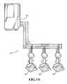
- FIG. 1Ais a schematic view of an HVAC system for delivering bipolar ionization to an airflow according to an example form of the present invention.
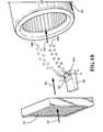
- FIG. 1Bis a detailed view of a portion of an air handler component of an HVAC system according to an example form of the present invention.
- FIG. 2Ashows a system for delivering bipolar ionization to an airflow within an internal combustion engine according to another example form of the present invention.
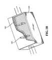
- FIG. 2Bis a detailed view of a filter housing portion of the system of FIG. 2 a according to an example form of the present invention.
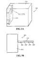
- FIGS. 3A and 3Bshow an ion generator control module and mounting assembly according to an example form of the present invention.
- FIG. 4shows a bipolar ion generator mounting assembly and delivery module according to an example form of the present invention.
- FIG. 5shows a bipolar ion generator mounting assembly and delivery module according to another example form of the present invention.
- FIG. 6shows a bipolar ion generator mounting assembly and delivery module according to another example form of the present invention.
- FIG. 1 ashows an HVAC system 10 according to one example form of the invention.
- the HVAC systemis a variable refrigerant volume (VRV) system having a shared outdoor heat exchanger 12 and a plurality of individual air handler units 14 , 16 , 18 .
- the HVAC systemcan take the form of a variable air volume (VAV), constant air volume (CAV), variable refrigerant flow (VRF) or other forms of heating, ventilation and air conditioning system.
- VAVvariable air volume
- CAVconstant air volume
- VRFvariable refrigerant flow
- the shared outdoor heat exchanger 12comprises a condenser coil, compressor and fan; the individual air handler units 14 , 16 , 18 each comprise a fan, expansion valve, heating/cooling coil(s), and a filter; and refrigerant lines connect the shared outdoor heat exchanger to the individual air handler units.
- Return air from the conditioned space and/or fresh air from an exterior spaceis treated and delivered to a conditioned air space via the individual air handler units 14 , 16 , 18 .
- the outdoor heat exchanger 12discharges waste heat from the conditioned air space to the ambient surroundings, and/or transfers heat from a cooled zone to a heated zone.
- FIG. 1 bshows internal components of an individual air handler unit according to an example form of the invention.
- An inlet airflow 30 flowing through a conduit such as the housing of the air handler unit or a ductis filtered through a filter 32 such as a mesh, screen, paper, cloth or other filter media.
- a filtered airflow 34 downstream of the filter 32is treated by discharge of bipolar ionization 36 from an ion generator 38 to form an ionized airflow 42 .
- the bipolar ionization 36comprises a stream of negatively charged ( ⁇ ) ions 36 a , and a stream of positively charged (+) ions 36 b .
- the ionized airflow 42enters the inlet of a fan or blower 44 for delivery to the treated air space, and is optionally heated or cooled by passing across or through a cooling coil or heating element.
- the coil, filter 32 , ion generator 38 and fan 44are optionally mounted within a housing of the air handler unit.
- Example modes of attachment of the ion generatorinclude, without limitation, adhesive, hook-and-loop fasteners, straps, screws, clips or other mechanical fasteners, magnetic mounting, and/or mounting brackets or carriers affixed to or through the housing or associated ductwork.
- the bipolar ion generator 38is preferably a tubeless ion generator and comprises at least one pair of air ionizing needlepoint electrodes 40 + (positive ion generation) and 40 ⁇ (negative ion generation) such as for example needles of stainless steel, carbon fiber, tungsten, steel or other metal; and optionally further comprising onboard control circuitry.
- the ion generatorpreferably produces approximately equal amounts of positive and negative ions, regardless of airflow velocity or other conditions such as humidity or temperature.
- each ion generator 38produces positive and negative ions in a concentration of at least about 10 9 ions/second, and operates on 12V DC, 110V AC, or other power source.
- the ion generator(s)generate negative ions only, or positive ions only, or generate negative and positive ions in unequal quantities.
- the ion generatoroptionally utilizes nano-electronic components allowing the ion generator to be very compact, requiring less than 1 watt/ion generator module, for example less than 0.5 watts/ion module, and in further examples less than 0.36 watts per ion module.
- the ion generatorproduces minimal or no ozone, for example at no greater concentration than in ambient air.
- Wiringmay be routed through the housing for connection to an external power source, and a power inverter may be included to convert the source voltage to the required input voltage of the ion generator.
- the ion generatorautomatically controls the ion discharge output based on preset algorithms, setpoints or other criteria, which may vary in relation to the airflow rate across the electrodes.
- the bipolar ion generator 38is positioned and secured in place within the housing of the air handler unit such that the electrodes 40 + and 40 ⁇ are aligned generally perpendicularly to the direction of the airflow 34 across the ion generator, to prevent recombination of the positively charged ions with the negatively charged ions.
- a vector representing the average flow velocity of the airflow 34is at approximately a right angle (90°) to an axis A extending between the electrodes 40 + and 40 ⁇ .
- One or more ion generator(s) 38can be installed within the housing of each air handler unit, as required to generate the desired level of ion delivery for a given airflow, as may be determined by the airflow rate (CFM) of the fan 44 and ion discharge rate of each ion generator.
- the ion generator(s)are preferably positioned generally centrally in relation to the airflow or evenly distributed across the airflow path. If more than one ion generator is provided in an air handler unit, they are sufficiently spaced and positioned relative to one another to minimize recombination of positive ions with negative ions.
- the system of the present inventionoptionally further comprises the application of ultraviolet (UV) light, and/or a catalyst such as for example TiO 2 for initiating photo-catalytic oxidation, in combination with ion generation, for abating allergens, pathogens, odors, gases, volatile organic compounds, bacteria, virus, mold, dander, fungus, dust mites, animal and smoke odors, and/or static electricity in a treated air space.
- UV lightultraviolet
- a catalystsuch as for example TiO 2 for initiating photo-catalytic oxidation, in combination with ion generation, for abating allergens, pathogens, odors, gases, volatile organic compounds, bacteria, virus, mold, dander, fungus, dust mites, animal and smoke odors, and/or static electricity in a treated air space.
- FIGS. 2 a and 2 bshow another system 110 for treating and delivering air according to the present invention, in this embodiment comprising an internal combustion engine 120 .
- the system 110includes an air intake conduit 122 containing an intake airflow and an exhaust conduit 124 containing an exhaust airflow.
- a filter housing 130is positioned within the air intake conduit 122 , and houses an air filter 132 in typical fashion.
- the filter 132comprises paper, non-woven material, or other filter media, and includes a series of pleats to provide an increased surface area for removal of particulate matter from the airflow.
- One or more bipolar ion generators 140are positioned within the filter housing 130 , for example mounted to the housing or retained between pleats of the filter 132 , for delivery of bipolar ionization to the intake air delivered for mixture with fuel and combustion in the engine.
- a tubeless needlepoint electrode ion generator operating on 12V DCadvantageously enables ease of retrofit and/or original equipment application, and connection via wiring to the electrical system of a vehicle driven by the engine 120 , preferably via a fused connection.
- the electrodes of the ion generator 140are aligned generally perpendicularly to the airflow to prevent ion recombination.
- the electrodesare sufficiently spaced and positioned to maintain the positive ion discharge unaligned with the negative ion discharge, for example by orienting the electrodes of different ion generators facing away from one another along the discharge side of the air filter 132 .
- One or more brackets or mountsare optionally provided for attachment of the system to the engine or other combustion gas delivery component.
- the treatment of air by delivery of bipolar ionization to an airflow within a conduitmay be utilized for various purposes.
- application of bipolar ionization to an airflow within an HVAC conduitsuch as an air handler housing or duct may be utilized to abate allergens, pathogens, odors, gases, volatile organic compounds, bacteria, virus, mold, dander, fungus, dust mites, animal and smoke odors, and/or static electricity in a treated air space to which the airflow is directed.
- Ionization of air in living and working spacesmay reduce building related illness and improve indoor air quality; and additionally can reduce the quantity of outside air needed to be mixed with the treated indoor air, reducing heating and cooling costs by enabling a greater degree of air recirculation.
- bipolar ionization to an airflow conduit in automotive applicationssuch as the intake to or exhaust from the engine may be utilized for removing particulates from the intake or exhaust flows, improving combustion efficiency, increasing the intake flowrate of combustion gas, increasing fuel mileage and/or performance, and/or reducing emissions.
- application of bipolar ionization to the intake air of an engine at a delivery rate of about 10 9 ions/second or greatermay break down water (H 2 O) vapor in the intake air through electrolysis and create elevated levels of oxygen (O 2 ) and hydrogen (H 2 ) in the air delivered to the engine for combustion.
- the provision of highly ionized intake air that is denser in O 2 and H 2 content than incoming ambient airresults in longer and/or hotter combustion of fuel, increasing cylinder pressure and creating more torque and horsepower for the same percentage of throttle and fuel consumption.
- the water content of the intake airmay be increased, for example by injection into the intake air stream from an external source of water such as a remote tank or the condensate from a vehicle's air conditioner, to further enhance the generation of oxygen and hydrogen by ionization.
- Ionization of the engine exhaust gassesmay effectively eliminate the need for a catalytic converter by agglomerating unburned carbon particulates to prevent their becoming airborne, and by dissociating undesirable emission constituents (for example dissociating NO x into N 2 and O 2 , dissociating SO x and S 2 and O 2 , dissociating CO into C and O 2 , etc.).
- the system and method of the present inventionmay be particularly advantageous in diesel engine applications, as well as in gasoline engine applications and other engine types.
- Water vapor molecules present in or added to the intake airmay be dissociated by application of bipolar ionization into H + , OH + , H ⁇ and OH ⁇ ions, OH, H, O, and/or HO 2 .
- the present inventionalso includes a number of ion generator carrier and mounting assemblies for application and control of delivery of bipolar ionization to an airflow.
- FIGS. 3 a and 3 bshow an example embodiment of an assembly 200 for mounting to the exterior of a duct, housing, or other conduit for an airflow.
- the assemblyincludes a box 210 or other enclosure, such as for example a NEMA 4 ⁇ enclosure or similar configuration, an internal panel 212 within the box, and an external arm 214 projecting from the back side of the box.
- the external arm 214includes mountings and electrical contacts for receiving one or more (four are depicted) bipolar ion generators 220 for delivery of bipolar ionization to an airflow within the conduit.
- the mountingssecurely engage the ion generators 220 and maintain them in an orientation having their electrodes axially aligned with the arm 214 and generally perpendicular to the airflow.
- the panel 212optionally comprises one or more pluggable terminal blocks for wiring connection to the ion generators via the contacts on the arm 214 , a connection for power input, and one or more indicators such as LEDs to indicate the presence/absence and operational state (on/off, ion output, etc.) of the ion generators.
- a power converter or transformeris provided in the box 210 for converting the input power to the power required to operate the ion generators.
- FIG. 4shows an assembly 300 according to an alternate embodiment, having a reclosable box 310 with an arm 314 extending therefrom, and otherwise being substantially similar to assembly 200 .
- the length of the arm 214may vary depending on the size of the conduit it is to be applied to and the number of ion generators to be installed, and in example embodiments is between 2′′-24′′, for example about 10′′ in length.
- FIG. 5show another embodiment of an ion generator mounting assembly 400 according to the present invention.
- the assembly 400includes an external power supply 410 for mounting external of the duct, housing or other conduit; and one or more ion generators 412 for mounting internal of the conduit for delivery of bipolar ionization to an airflow within the conduit.
- Wires 414 extending between the external power supply 410 and the ion generators 412pass through an opening in the wall of the conduit to deliver power from the power supply to the ion generators.
- the external power supply 410optionally comprises control circuitry and/or indicators for displaying the operational state of the ion generators.
- FIG. 6shows another embodiment of an ion generator mounting assembly 500 according to the present invention.
- the assembly 500includes a control panel 510 for mounting external of the duct, housing or other conduit, and an internal rack 512 for mounting in the conduit's interior.
- the rack 512includes electrical couplings and mounting receivers for receiving at least one, and preferably a plurality of ion generators for delivery of bipolar ionization to an airflow within the conduit.
Landscapes
- Engineering & Computer Science (AREA)
- Chemical & Material Sciences (AREA)
- Combustion & Propulsion (AREA)
- General Engineering & Computer Science (AREA)
- Mechanical Engineering (AREA)
- Chemical Kinetics & Catalysis (AREA)
- Analytical Chemistry (AREA)
- Health & Medical Sciences (AREA)
- Physics & Mathematics (AREA)
- Plasma & Fusion (AREA)
- Manufacturing & Machinery (AREA)
- Automation & Control Theory (AREA)
- Epidemiology (AREA)
- General Health & Medical Sciences (AREA)
- Public Health (AREA)
- Veterinary Medicine (AREA)
- Animal Behavior & Ethology (AREA)
- Life Sciences & Earth Sciences (AREA)
- Toxicology (AREA)
- Disinfection, Sterilisation Or Deodorisation Of Air (AREA)
- Air-Conditioning For Vehicles (AREA)
- Elimination Of Static Electricity (AREA)
- Electrostatic Separation (AREA)
Abstract
Description
Claims (20)
Priority Applications (2)
| Application Number | Priority Date | Filing Date | Title |
|---|---|---|---|
| US15/293,519US9839714B2 (en) | 2008-10-14 | 2016-10-14 | Ion generator device |
| US15/804,618US10111978B2 (en) | 2008-10-14 | 2017-11-06 | Ion generator device |
Applications Claiming Priority (7)
| Application Number | Priority Date | Filing Date | Title |
|---|---|---|---|
| US10511008P | 2008-10-14 | 2008-10-14 | |
| US22176309P | 2009-06-30 | 2009-06-30 | |
| US12/578,753US8564924B1 (en) | 2008-10-14 | 2009-10-14 | Systems and methods of air treatment using bipolar ionization |
| US14/036,882US8861168B2 (en) | 2008-10-14 | 2013-09-25 | Ion generator device |
| US14/480,120US9289779B2 (en) | 2008-10-14 | 2014-09-08 | Ion generator device |
| US15/040,087US9509125B2 (en) | 2008-10-14 | 2016-02-10 | Ion generator device |
| US15/293,519US9839714B2 (en) | 2008-10-14 | 2016-10-14 | Ion generator device |
Related Parent Applications (1)
| Application Number | Title | Priority Date | Filing Date |
|---|---|---|---|
| US15/040,087ContinuationUS9509125B2 (en) | 2008-10-14 | 2016-02-10 | Ion generator device |
Related Child Applications (1)
| Application Number | Title | Priority Date | Filing Date |
|---|---|---|---|
| US15/804,618ContinuationUS10111978B2 (en) | 2008-10-14 | 2017-11-06 | Ion generator device |
Publications (2)
| Publication Number | Publication Date |
|---|---|
| US20170028096A1 US20170028096A1 (en) | 2017-02-02 |
| US9839714B2true US9839714B2 (en) | 2017-12-12 |
Family
ID=49355266
Family Applications (13)
| Application Number | Title | Priority Date | Filing Date |
|---|---|---|---|
| US12/578,753Active2032-06-27US8564924B1 (en) | 2008-10-14 | 2009-10-14 | Systems and methods of air treatment using bipolar ionization |
| US14/021,507ActiveUS9025303B2 (en) | 2008-10-14 | 2013-09-09 | Ion generation device |
| US14/036,173Expired - Fee RelatedUS8873215B2 (en) | 2008-10-14 | 2013-09-25 | Ion generator mounting device |
| US14/036,882ActiveUS8861168B2 (en) | 2008-10-14 | 2013-09-25 | Ion generator device |
| US14/480,120Active2029-11-26US9289779B2 (en) | 2008-10-14 | 2014-09-08 | Ion generator device |
| US14/480,164ActiveUS9168538B2 (en) | 2008-10-14 | 2014-09-08 | Ion generator mounting device |
| US14/632,221AbandonedUS20150165084A1 (en) | 2008-10-14 | 2015-02-26 | Ion generation device |
| US14/861,469ActiveUS9478948B2 (en) | 2008-10-14 | 2015-09-22 | Ion generator mounting device |
| US15/040,087ActiveUS9509125B2 (en) | 2008-10-14 | 2016-02-10 | Ion generator device |
| US15/268,717Active2030-01-03US9925292B2 (en) | 2008-10-14 | 2016-09-19 | Ion generator mounting device |
| US15/293,519ActiveUS9839714B2 (en) | 2008-10-14 | 2016-10-14 | Ion generator device |
| US15/804,618ActiveUS10111978B2 (en) | 2008-10-14 | 2017-11-06 | Ion generator device |
| US15/896,395ActiveUS10383970B2 (en) | 2008-10-14 | 2018-02-14 | Ion generator mounting device |
Family Applications Before (10)
| Application Number | Title | Priority Date | Filing Date |
|---|---|---|---|
| US12/578,753Active2032-06-27US8564924B1 (en) | 2008-10-14 | 2009-10-14 | Systems and methods of air treatment using bipolar ionization |
| US14/021,507ActiveUS9025303B2 (en) | 2008-10-14 | 2013-09-09 | Ion generation device |
| US14/036,173Expired - Fee RelatedUS8873215B2 (en) | 2008-10-14 | 2013-09-25 | Ion generator mounting device |
| US14/036,882ActiveUS8861168B2 (en) | 2008-10-14 | 2013-09-25 | Ion generator device |
| US14/480,120Active2029-11-26US9289779B2 (en) | 2008-10-14 | 2014-09-08 | Ion generator device |
| US14/480,164ActiveUS9168538B2 (en) | 2008-10-14 | 2014-09-08 | Ion generator mounting device |
| US14/632,221AbandonedUS20150165084A1 (en) | 2008-10-14 | 2015-02-26 | Ion generation device |
| US14/861,469ActiveUS9478948B2 (en) | 2008-10-14 | 2015-09-22 | Ion generator mounting device |
| US15/040,087ActiveUS9509125B2 (en) | 2008-10-14 | 2016-02-10 | Ion generator device |
| US15/268,717Active2030-01-03US9925292B2 (en) | 2008-10-14 | 2016-09-19 | Ion generator mounting device |
Family Applications After (2)
| Application Number | Title | Priority Date | Filing Date |
|---|---|---|---|
| US15/804,618ActiveUS10111978B2 (en) | 2008-10-14 | 2017-11-06 | Ion generator device |
| US15/896,395ActiveUS10383970B2 (en) | 2008-10-14 | 2018-02-14 | Ion generator mounting device |
Country Status (1)
| Country | Link |
|---|---|
| US (13) | US8564924B1 (en) |
Cited By (6)
| Publication number | Priority date | Publication date | Assignee | Title |
|---|---|---|---|---|
| US10111978B2 (en)* | 2008-10-14 | 2018-10-30 | Global Plasma Solutions, Inc. | Ion generator device |
| US11027038B1 (en) | 2020-05-22 | 2021-06-08 | Delta T, Llc | Fan for improving air quality |
| US11103881B2 (en)* | 2018-08-02 | 2021-08-31 | Faurecia Interior Systems, Inc. | Air vent |
| US11400177B2 (en) | 2020-05-18 | 2022-08-02 | Wangs Alliance Corporation | Germicidal lighting |
| USD996367S1 (en) | 2021-08-12 | 2023-08-22 | Dometic Sweden Ab | Housing for an ion generator |
| USD999739S1 (en) | 2021-08-12 | 2023-09-26 | Dometic Sweden Ab | Housing for an ion generator |
Families Citing this family (52)
| Publication number | Priority date | Publication date | Assignee | Title |
|---|---|---|---|---|
| WO2013188759A1 (en)* | 2012-06-15 | 2013-12-19 | Global Plasma Solutions, Llc | Ion generation device |
| US9353966B2 (en) | 2013-03-15 | 2016-05-31 | Iaire L.L.C. | System for increasing operating efficiency of an HVAC system including air ionization |
| JP6264169B2 (en)* | 2014-04-15 | 2018-01-24 | トヨタ自動車株式会社 | Oil removal equipment |
| JP2016080563A (en)* | 2014-10-20 | 2016-05-16 | 日本光電工業株式会社 | Analysis system and analyzer |
| US10319569B2 (en)* | 2014-12-19 | 2019-06-11 | Global Plasma Solutions, Inc. | Self cleaning ion generator device |
| US9925567B2 (en)* | 2014-12-19 | 2018-03-27 | Global Plasma Solutions, Llc | Self cleaning ion generator |
| US9847623B2 (en) | 2014-12-24 | 2017-12-19 | Plasma Air International, Inc | Ion generating device enclosure |
| JP6771022B2 (en)* | 2015-04-30 | 2020-10-21 | シナジェテック ジェネシス インターナショナル リミテッド | A method for optimizing combustion in a combustion device and a device for carrying out the method. |
| US10088178B2 (en) | 2015-05-05 | 2018-10-02 | MJC, Inc. | Multi-zone variable refrigerant flow heating/cooling unit |
| US10111977B1 (en)* | 2015-07-01 | 2018-10-30 | Terrance Woodbridge | Method and system for generating non-thermal plasma |
| JP6612084B2 (en)* | 2015-08-05 | 2019-11-27 | シャープ株式会社 | Ion generator and electrical equipment |
| US10128075B2 (en)* | 2015-10-19 | 2018-11-13 | Global Plasma Solutions, Inc. | Ion generation device having attachment devices |
| US9660425B1 (en) | 2015-12-30 | 2017-05-23 | Plasma Air International, Inc | Ion generator device support |
| US10980911B2 (en) | 2016-01-21 | 2021-04-20 | Global Plasma Solutions, Inc. | Flexible ion generator device |
| WO2017131769A1 (en) | 2016-01-29 | 2017-08-03 | Optimized Fuel Technologies, Inc. | Ionizing device for improving combustion engine performance and methods of use |
| US20170354980A1 (en) | 2016-06-14 | 2017-12-14 | Pacific Air Filtration Holdings, LLC | Collecting electrode |
| US10882053B2 (en) | 2016-06-14 | 2021-01-05 | Agentis Air Llc | Electrostatic air filter |
| US10828646B2 (en) | 2016-07-18 | 2020-11-10 | Agentis Air Llc | Electrostatic air filter |
| US11283245B2 (en) | 2016-08-08 | 2022-03-22 | Global Plasma Solutions, Inc. | Modular ion generator device |
| US10020180B2 (en)* | 2016-08-08 | 2018-07-10 | Global Plasma Solutions, Llc | Modular ion generator device |
| US11695259B2 (en) | 2016-08-08 | 2023-07-04 | Global Plasma Solutions, Inc. | Modular ion generator device |
| US10046494B2 (en)* | 2016-09-07 | 2018-08-14 | BetaJet, LLC | Small format reaction injection molding machines and components for use therein |
| US10871304B2 (en)* | 2016-11-07 | 2020-12-22 | Air Distribution Technologies Ip, Llc | Air diffuser |
| AU2018255508B2 (en)* | 2017-04-21 | 2023-05-11 | Smac Technologies Pty Ltd | Air conditioning system with reduced mould growth conditions |
| US10697690B2 (en)* | 2017-11-07 | 2020-06-30 | Air Oasis Llc | Ice machine cleaning system and method of use |
| WO2019126941A1 (en)* | 2017-12-25 | 2019-07-04 | 惠州市杜科新材料有限公司 | Oil bath type air filter with electrostatic filtration |
| US10786818B2 (en)* | 2018-02-09 | 2020-09-29 | Aviation Clean Air, Llc | Aircraft proactive air and surface purification component |
| US11344922B2 (en) | 2018-02-12 | 2022-05-31 | Global Plasma Solutions, Inc. | Self cleaning ion generator device |
| CN108361129A (en)* | 2018-02-27 | 2018-08-03 | 沈阳航空航天大学 | A kind of movable electrode structure air inlet suitable for internal combustion engine ionizes combustion-supporting driver |
| US10704444B2 (en)* | 2018-08-21 | 2020-07-07 | Tenneco Automotive Operating Company Inc. | Injector fluid filter with upper and lower lip seal |
| US11246955B2 (en) | 2018-10-29 | 2022-02-15 | Phoenixaire, Llc | Method and system for generating non-thermal plasma |
| US10792673B2 (en) | 2018-12-13 | 2020-10-06 | Agentis Air Llc | Electrostatic air cleaner |
| US10875034B2 (en) | 2018-12-13 | 2020-12-29 | Agentis Air Llc | Electrostatic precipitator |
| US11581709B2 (en) | 2019-06-07 | 2023-02-14 | Global Plasma Solutions, Inc. | Self-cleaning ion generator device |
| CN110454888A (en)* | 2019-08-16 | 2019-11-15 | 大连理工大学 | Energy-saving and environment-friendly air purification device for building renovation |
| CN111150936B (en)* | 2019-11-04 | 2020-12-18 | 刘延兵 | Charged particle wave generation method and device |
| US11772103B2 (en) | 2020-03-27 | 2023-10-03 | Praan Inc. | Filter-less intelligent air purification device |
| US11875974B2 (en) | 2020-05-30 | 2024-01-16 | Preservation Tech, LLC | Multi-channel plasma reaction cell |
| US20220011013A1 (en)* | 2020-07-09 | 2022-01-13 | Carson Design and Manufacturing Inc. | Displacement induction environmental sanitizing control system |
| US20220111105A1 (en)* | 2020-10-14 | 2022-04-14 | Chenghung Pan | Multifunction uv disinfecting fixture |
| USD934404S1 (en) | 2020-11-19 | 2021-10-26 | Mallie Jamieson Seckinger, SR. | Ion distribution device |
| CN114909759A (en) | 2021-02-07 | 2022-08-16 | 开利公司 | Air purifying device |
| US11173226B1 (en) | 2021-04-29 | 2021-11-16 | Robert J. Mowris | Balanced bipolar ionizer based on unbalanced high-voltage output |
| US12038204B2 (en) | 2021-04-29 | 2024-07-16 | James Lau | Ionizer feedback control |
| US11563310B2 (en) | 2021-04-29 | 2023-01-24 | John Walsh | Bipolar ionizer with feedback control |
| US12338835B1 (en) | 2021-05-13 | 2025-06-24 | Scentair Technologies, Llc | Fan diffuser assembly and method |
| EP4392698A1 (en)* | 2021-08-27 | 2024-07-03 | Global Plasma Solutions, Inc. | Duct adaptor for an ion generation device and ion generation device for use therein |
| US11471551B1 (en) | 2021-09-09 | 2022-10-18 | Micron Pure, Llc | Apparatus for inactivation of airborne pathogens |
| US20230102854A1 (en)* | 2021-09-24 | 2023-03-30 | Jackson Control Co., Inc. | Air ionization system for a transit vehicle |
| US12057681B1 (en) | 2021-10-06 | 2024-08-06 | Bionic Aire International Co. Ltd. | Self-powered ionization device |
| KR102538501B1 (en)* | 2022-09-06 | 2023-06-01 | 주식회사 이글엑스코리아 | Total heat exchanger with air purification and sterilization function |
| USD1073136S1 (en) | 2023-01-23 | 2025-04-29 | Crawford Glogal Limited | Plasma generator |
Citations (79)
| Publication number | Priority date | Publication date | Assignee | Title |
|---|---|---|---|---|
| US3744216A (en) | 1970-08-07 | 1973-07-10 | Environmental Technology | Air purifier |
| US3804942A (en) | 1971-11-16 | 1974-04-16 | Shimizu Construction Co Ltd | Air purifier |
| US3956458A (en) | 1973-11-16 | 1976-05-11 | Paul Brent Anderson | Method and apparatus for air purification |
| US4048668A (en) | 1975-05-09 | 1977-09-13 | Source Gas Analyzers, Inc. | Electrically driven high voltage ozonator |
| US4244710A (en) | 1977-05-12 | 1981-01-13 | Burger Manfred R | Air purification electrostatic charcoal filter and method |
| US4308844A (en) | 1979-06-08 | 1982-01-05 | Persinger James G | Method and apparatus for improving efficiency in combustion engines |
| US4417966A (en) | 1980-11-15 | 1983-11-29 | Innovatron Krauss & Co. | Apparatus and method of producing ozone |
| US4519357A (en) | 1982-09-29 | 1985-05-28 | Am-Air Limited Partnership | Air ionizer for internal combustion engines |
| US4538582A (en) | 1983-02-04 | 1985-09-03 | Johoku Kogyo Kabushiki Kaisha | Method of combusting fuel in an internal combustion engine and its apparatus |
| US4597781A (en) | 1984-11-21 | 1986-07-01 | Donald Spector | Compact air purifier unit |
| US4757422A (en) | 1986-09-15 | 1988-07-12 | Voyager Technologies, Inc. | Dynamically balanced ionization blower |
| US4809127A (en) | 1987-08-11 | 1989-02-28 | Ion Systems, Inc. | Self-regulating air ionizing apparatus |
| US4828586A (en) | 1985-11-13 | 1989-05-09 | Joannou Constantinos J | Cartridge type electronic air filter |
| US4886526A (en) | 1987-04-22 | 1989-12-12 | Joannou Costantinos J | Electronic air filtration system |
| US4901194A (en) | 1988-07-20 | 1990-02-13 | Ion Systems, Inc. | Method and apparatus for regulating air ionization |
| US5010869A (en) | 1989-08-11 | 1991-04-30 | Zenion Industries, Inc. | Air ionization system for internal combustion engines |
| US5055115A (en) | 1988-12-23 | 1991-10-08 | Hiroaki Kanazawa | Air cleaner including an electrostatic precipitator |
| US5055963A (en) | 1990-08-15 | 1991-10-08 | Ion Systems, Inc. | Self-balancing bipolar air ionizer |
| US5108470A (en) | 1988-11-01 | 1992-04-28 | William Pick | Charging element having odor and gas absorbing properties for an electrostatic air filter |
| US5185015A (en) | 1991-03-18 | 1993-02-09 | Searle Bruce R | Filter apparatus |
| US5474599A (en) | 1992-08-11 | 1995-12-12 | United Air Specialists, Inc. | Apparatus for electrostatically cleaning particulates from air |
| US5486410A (en) | 1992-11-18 | 1996-01-23 | Hoechst Celanese Corporation | Fibrous structures containing immobilized particulate matter |
| US5487874A (en) | 1992-05-27 | 1996-01-30 | Scientific Products Corporation | Air intake system for an internal combustion engine |
| US5573577A (en) | 1995-01-17 | 1996-11-12 | Joannou; Constantinos J. | Ionizing and polarizing electronic air filter |
| US5616172A (en) | 1996-02-27 | 1997-04-01 | Nature's Quarters, Inc. | Air treatment system |
| US5656063A (en) | 1996-01-29 | 1997-08-12 | Airlux Electrical Co., Ltd. | Air cleaner with separate ozone and ionizer outputs and method of purifying air |
| US5681374A (en) | 1993-06-18 | 1997-10-28 | Freshman Ab | Device for the separation of microscopic particles out of air |
| US5702507A (en) | 1996-09-17 | 1997-12-30 | Yih Change Enterprise Co., Ltd. | Automatic air cleaner |
| US5707429A (en) | 1996-09-25 | 1998-01-13 | Lewis Lint Trap, Inc. | Ionizing structure for ambient air treatment |
| US5807425A (en) | 1993-07-17 | 1998-09-15 | Gibbs; Robert William | Electrofilter |
| US5837207A (en) | 1997-04-17 | 1998-11-17 | Engineering Dynamics Limited | Portable germicidal air filter |
| US5846302A (en) | 1997-04-24 | 1998-12-08 | Aqua-Air Technologies, Inc. | Electrostatic air filter device |
| US5950424A (en) | 1995-10-24 | 1999-09-14 | Kabushiki Kaisya O - Den | Diesel engine exhaust particle collection device |
| US5977716A (en) | 1995-12-28 | 1999-11-02 | Motouchi; Kazuo | Ion generator for a combustion device |
| US6002573A (en) | 1998-01-14 | 1999-12-14 | Ion Systems, Inc. | Self-balancing shielded bipolar ionizer |
| US6036738A (en) | 1997-12-31 | 2000-03-14 | Shanbrom Technologies Llc | Disinfecting gas filters |
| US6053968A (en) | 1998-10-14 | 2000-04-25 | Miller; Bob C. | Portable room air purifier |
| US6058698A (en) | 1995-10-13 | 2000-05-09 | Coral S.P.A. | Device for purifying the exhaust gas of an internal combustion engine |
| US6063167A (en) | 1997-05-05 | 2000-05-16 | Rutkowski; Timothy C. | Frameless electrostatic air filter with internal support grill |
| US6090184A (en) | 1998-02-27 | 2000-07-18 | Hmi Industries, Inc. | Filter system |
| US6149717A (en) | 1997-01-06 | 2000-11-21 | Carrier Corporation | Electronic air cleaner with germicidal lamp |
| US6322614B1 (en) | 1996-12-18 | 2001-11-27 | Kurt Tillmans | Device for high-purity filtering and disinfecting breathing air |
| US6463917B1 (en) | 2001-10-29 | 2002-10-15 | Jack Silver | Device for improving combustion and eliminating pollutants from internal combustion engines |
| US6471752B1 (en) | 2000-10-16 | 2002-10-29 | Lewis Lint Trap, Inc. | Ionizing structure for ambient air treatment |
| US6536418B1 (en) | 2002-03-07 | 2003-03-25 | Yuan-Hung Ling | Combustion enhancement device for internal combustion engines |
| US6601570B2 (en) | 2001-06-22 | 2003-08-05 | Karl D. Zetmeir | Self contained air flow and ionization method, apparatus and design for internal combustion engines |
| US6610123B2 (en) | 2001-12-17 | 2003-08-26 | Intel Corporation | Filtered mask enclosure |
| US6693788B1 (en) | 2001-05-09 | 2004-02-17 | Ion Systems | Air ionizer with static balance control |
| US6752970B2 (en) | 2001-08-14 | 2004-06-22 | Shaklee Corporation | Air treatment apparatus and methods |
| US6764533B2 (en) | 2001-10-30 | 2004-07-20 | Joseph A. Liobiondo, Sr. | Electronic air filter assembly |
| US6785114B2 (en) | 2001-03-29 | 2004-08-31 | Illinois Tool Works Inc. | Foraminous filter for use in air ionizer |
| US6805732B1 (en) | 1999-11-23 | 2004-10-19 | Airinspace Ltd. | Electrostatic treatment of aerosols, devices and method for producing same |
| US6850403B1 (en) | 2001-11-30 | 2005-02-01 | Ion Systems, Inc. | Air ionizer and method |
| US20050123436A1 (en) | 2002-04-16 | 2005-06-09 | Cumberland John R. | Method for abatement of allergens, pathogens and volatile organic compounds |
| US20050142047A1 (en) | 2003-12-31 | 2005-06-30 | Hyundai Motor Company | Hybrid-type air purifier for an automobile |
| US7132010B2 (en) | 2003-10-21 | 2006-11-07 | Scandfilter Ab | Air filtering system |
| US7177133B2 (en) | 2002-04-09 | 2007-02-13 | Ionic Systems Ltd. | Method and apparatus for bipolar ion generation |
| US7256979B2 (en) | 2001-08-01 | 2007-08-14 | Sharp Kabushiki Kaisha | Ion generator, and electric apparatus and air conditioning apparatus incorporating the same |
| US7258729B1 (en) | 2004-08-04 | 2007-08-21 | Air Ion Devices Inc. | Electronic bi-polar electrostatic air cleaner |
| US7311752B2 (en) | 2005-09-12 | 2007-12-25 | Argonide Corporation | Electrostatic air filter |
| WO2008004454A1 (en) | 2006-07-06 | 2008-01-10 | Sharp Kabushiki Kaisha | Ion generating apparatus and electric apparatus |
| US7318856B2 (en) | 1998-11-05 | 2008-01-15 | Sharper Image Corporation | Air treatment apparatus having an electrode extending along an axis which is substantially perpendicular to an air flow path |
| US7341049B2 (en) | 2005-07-15 | 2008-03-11 | David M Clack | Apparatus for improving efficiency and emissions of combustion |
| US7347888B2 (en) | 2005-04-29 | 2008-03-25 | Sylmark Holdings Limited | Air purifier |
| US7368003B2 (en) | 2005-06-24 | 2008-05-06 | S.C. Johnson & Son, Inc. | Systems for and methods of providing air purification in combination with odor elimination |
| WO2008054125A1 (en) | 2006-10-31 | 2008-05-08 | Halla Climate Control Corp. | Ionizer and air conditioning system for automotive vehicles using the same |
| US7384619B2 (en) | 2003-06-30 | 2008-06-10 | Bar-Gadda, Llc | Method for generating hydrogen from water or steam in a plasma |
| US7407624B2 (en) | 2002-04-16 | 2008-08-05 | Prompt Care, Inc. | Method for abatement of allergens, pathogens and volatile organic compounds |
| US7475656B2 (en) | 2006-03-14 | 2009-01-13 | Yuriy Yatsenko | Hydrogen and oxygen production and accumulating apparatus including an internal combustion engine and method |
| US20100008010A1 (en) | 2008-07-08 | 2010-01-14 | Smc Corporation | Ionizer |
| US20100018398A1 (en) | 2008-01-22 | 2010-01-28 | Scott Steven Krell | Assembly and housing for duct system |
| US7691335B2 (en) | 2004-07-27 | 2010-04-06 | Samsung Electronics Co., Ltd. | Sterilizing method, sterilizing apparatus, and air cleaning method and apparatus using the same |
| US7749313B2 (en) | 2007-04-12 | 2010-07-06 | Halla Climate Control Corp. | Air conditioning system for automotive vehicles |
| US20100247389A1 (en) | 2007-11-13 | 2010-09-30 | Abate Anthony M | Bipolar ionization tube |
| US20100251889A1 (en) | 2007-10-29 | 2010-10-07 | Shunji Haruna | Charging device, air handling device, method for charging, and method for handling air |
| US7858054B2 (en) | 2006-07-12 | 2010-12-28 | Romeo Manalo | Device for reforming gas vapor of an internal combustion engine |
| US7906080B1 (en) | 2003-09-05 | 2011-03-15 | Sharper Image Acquisition Llc | Air treatment apparatus having a liquid holder and a bipolar ionization device |
| US8106367B2 (en) | 2009-12-30 | 2012-01-31 | Filt Air Ltd. | Method and ionizer for bipolar ion generation |
| US8564924B1 (en) | 2008-10-14 | 2013-10-22 | Global Plasma Solutions, Llc | Systems and methods of air treatment using bipolar ionization |
Family Cites Families (24)
| Publication number | Priority date | Publication date | Assignee | Title |
|---|---|---|---|---|
| US4048667A (en) | 1975-08-13 | 1977-09-13 | Hermann Brennecke | Device for discharging static electricity |
| US4454621A (en) | 1982-01-15 | 1984-06-19 | Static Inc. | Sheet and web cleaner |
| GB9013621D0 (en) | 1990-06-19 | 1990-08-08 | Neg Ions Limited | Dust extraction from air by negative ionization |
| US5664231A (en) | 1994-04-29 | 1997-09-02 | Tps Electronics | PCMCIA interface card for coupling input devices such as barcode scanning engines to personal digital assistants and palmtop computers |
| US5550703A (en) | 1995-01-31 | 1996-08-27 | Richmond Technology, Inc. | Particle free ionization bar |
| US5741352A (en)* | 1996-08-19 | 1998-04-21 | Jing Mei Industrial Holdings, Ltd. | Air cleaner |
| US6680033B2 (en)* | 2000-07-25 | 2004-01-20 | Asahi Environmental System Ltd. | Composite deodorization system and ion deodorization system |
| US6807044B1 (en) | 2003-05-01 | 2004-10-19 | Ion Systems, Inc. | Corona discharge apparatus and method of manufacture |
| JP2005142131A (en) | 2003-11-10 | 2005-06-02 | Fuji Photo Film Co Ltd | Static eliminator |
| JP4345060B2 (en) | 2004-11-30 | 2009-10-14 | Smc株式会社 | Ionizer |
| KR100759587B1 (en) | 2005-04-19 | 2007-09-17 | (주)선재하이테크 | Bar ionizer |
| KR101104101B1 (en) | 2005-06-20 | 2012-01-12 | 휴글엘렉트로닉스가부시키가이샤 | Discharge Unit for AC Type Ionizer |
| US7537647B2 (en) | 2005-08-10 | 2009-05-26 | S.C. Johnson & Son, Inc. | Air purifier |
| US7497898B2 (en) | 2006-10-31 | 2009-03-03 | Smc Corporation | Ionizer |
| US7909918B2 (en) | 2007-08-15 | 2011-03-22 | Trane International, Inc. | Air filtration system |
| JP5154216B2 (en) | 2007-12-28 | 2013-02-27 | 株式会社キーエンス | Static eliminator |
| JP5002450B2 (en) | 2007-12-28 | 2012-08-15 | 株式会社キーエンス | Static eliminator and discharge electrode unit incorporated therein |
| JP5002451B2 (en) | 2007-12-28 | 2012-08-15 | 株式会社キーエンス | Static eliminator |
| WO2010014635A1 (en) | 2008-07-28 | 2010-02-04 | Bioclimatic Air Systems | Bi-polar ionization tube base and tube socket |
| JP5319203B2 (en) | 2008-08-19 | 2013-10-16 | 株式会社キーエンス | Static eliminator |
| US8038775B2 (en) | 2009-04-24 | 2011-10-18 | Peter Gefter | Separating contaminants from gas ions in corona discharge ionizing bars |
| US8173976B2 (en) | 2009-07-24 | 2012-05-08 | Agilent Technologies, Inc. | Linear ion processing apparatus with improved mechanical isolation and assembly |
| IL202219A (en)* | 2009-11-19 | 2013-03-24 | Filt Air Ltd | Method of bipolar ion generation and aerodynamic ion generator |
| US9421291B2 (en) | 2011-05-12 | 2016-08-23 | Fifth Third Bank | Hand dryer with sanitizing ionization assembly |
- 2009
- 2009-10-14USUS12/578,753patent/US8564924B1/enactiveActive
- 2013
- 2013-09-09USUS14/021,507patent/US9025303B2/enactiveActive
- 2013-09-25USUS14/036,173patent/US8873215B2/ennot_activeExpired - Fee Related
- 2013-09-25USUS14/036,882patent/US8861168B2/enactiveActive
- 2014
- 2014-09-08USUS14/480,120patent/US9289779B2/enactiveActive
- 2014-09-08USUS14/480,164patent/US9168538B2/enactiveActive
- 2015
- 2015-02-26USUS14/632,221patent/US20150165084A1/ennot_activeAbandoned
- 2015-09-22USUS14/861,469patent/US9478948B2/enactiveActive
- 2016
- 2016-02-10USUS15/040,087patent/US9509125B2/enactiveActive
- 2016-09-19USUS15/268,717patent/US9925292B2/enactiveActive
- 2016-10-14USUS15/293,519patent/US9839714B2/enactiveActive
- 2017
- 2017-11-06USUS15/804,618patent/US10111978B2/enactiveActive
- 2018
- 2018-02-14USUS15/896,395patent/US10383970B2/enactiveActive
Patent Citations (85)
| Publication number | Priority date | Publication date | Assignee | Title |
|---|---|---|---|---|
| US3744216A (en) | 1970-08-07 | 1973-07-10 | Environmental Technology | Air purifier |
| US3804942A (en) | 1971-11-16 | 1974-04-16 | Shimizu Construction Co Ltd | Air purifier |
| US3956458A (en) | 1973-11-16 | 1976-05-11 | Paul Brent Anderson | Method and apparatus for air purification |
| US4048668A (en) | 1975-05-09 | 1977-09-13 | Source Gas Analyzers, Inc. | Electrically driven high voltage ozonator |
| US4244710A (en) | 1977-05-12 | 1981-01-13 | Burger Manfred R | Air purification electrostatic charcoal filter and method |
| US4308844A (en) | 1979-06-08 | 1982-01-05 | Persinger James G | Method and apparatus for improving efficiency in combustion engines |
| US4417966A (en) | 1980-11-15 | 1983-11-29 | Innovatron Krauss & Co. | Apparatus and method of producing ozone |
| US4519357A (en) | 1982-09-29 | 1985-05-28 | Am-Air Limited Partnership | Air ionizer for internal combustion engines |
| US4538582A (en) | 1983-02-04 | 1985-09-03 | Johoku Kogyo Kabushiki Kaisha | Method of combusting fuel in an internal combustion engine and its apparatus |
| US4597781A (en) | 1984-11-21 | 1986-07-01 | Donald Spector | Compact air purifier unit |
| US4828586A (en) | 1985-11-13 | 1989-05-09 | Joannou Constantinos J | Cartridge type electronic air filter |
| US4757422A (en) | 1986-09-15 | 1988-07-12 | Voyager Technologies, Inc. | Dynamically balanced ionization blower |
| US4886526A (en) | 1987-04-22 | 1989-12-12 | Joannou Costantinos J | Electronic air filtration system |
| US4809127A (en) | 1987-08-11 | 1989-02-28 | Ion Systems, Inc. | Self-regulating air ionizing apparatus |
| US4901194A (en) | 1988-07-20 | 1990-02-13 | Ion Systems, Inc. | Method and apparatus for regulating air ionization |
| US4951172A (en) | 1988-07-20 | 1990-08-21 | Ion Systems, Inc. | Method and apparatus for regulating air ionization |
| US5108470A (en) | 1988-11-01 | 1992-04-28 | William Pick | Charging element having odor and gas absorbing properties for an electrostatic air filter |
| US5055115A (en) | 1988-12-23 | 1991-10-08 | Hiroaki Kanazawa | Air cleaner including an electrostatic precipitator |
| US5010869A (en) | 1989-08-11 | 1991-04-30 | Zenion Industries, Inc. | Air ionization system for internal combustion engines |
| US5055963A (en) | 1990-08-15 | 1991-10-08 | Ion Systems, Inc. | Self-balancing bipolar air ionizer |
| US6118645A (en) | 1990-08-15 | 2000-09-12 | Ion Systems, Inc. | Self-balancing bipolar air ionizer |
| US5185015A (en) | 1991-03-18 | 1993-02-09 | Searle Bruce R | Filter apparatus |
| US5487874A (en) | 1992-05-27 | 1996-01-30 | Scientific Products Corporation | Air intake system for an internal combustion engine |
| US5474599A (en) | 1992-08-11 | 1995-12-12 | United Air Specialists, Inc. | Apparatus for electrostatically cleaning particulates from air |
| US5486410A (en) | 1992-11-18 | 1996-01-23 | Hoechst Celanese Corporation | Fibrous structures containing immobilized particulate matter |
| US5681374A (en) | 1993-06-18 | 1997-10-28 | Freshman Ab | Device for the separation of microscopic particles out of air |
| US5807425A (en) | 1993-07-17 | 1998-09-15 | Gibbs; Robert William | Electrofilter |
| US5573577A (en) | 1995-01-17 | 1996-11-12 | Joannou; Constantinos J. | Ionizing and polarizing electronic air filter |
| US6058698A (en) | 1995-10-13 | 2000-05-09 | Coral S.P.A. | Device for purifying the exhaust gas of an internal combustion engine |
| US5950424A (en) | 1995-10-24 | 1999-09-14 | Kabushiki Kaisya O - Den | Diesel engine exhaust particle collection device |
| US5977716A (en) | 1995-12-28 | 1999-11-02 | Motouchi; Kazuo | Ion generator for a combustion device |
| US5656063A (en) | 1996-01-29 | 1997-08-12 | Airlux Electrical Co., Ltd. | Air cleaner with separate ozone and ionizer outputs and method of purifying air |
| US5616172A (en) | 1996-02-27 | 1997-04-01 | Nature's Quarters, Inc. | Air treatment system |
| US5702507A (en) | 1996-09-17 | 1997-12-30 | Yih Change Enterprise Co., Ltd. | Automatic air cleaner |
| US5707429A (en) | 1996-09-25 | 1998-01-13 | Lewis Lint Trap, Inc. | Ionizing structure for ambient air treatment |
| US6322614B1 (en) | 1996-12-18 | 2001-11-27 | Kurt Tillmans | Device for high-purity filtering and disinfecting breathing air |
| US6149717A (en) | 1997-01-06 | 2000-11-21 | Carrier Corporation | Electronic air cleaner with germicidal lamp |
| US5837207A (en) | 1997-04-17 | 1998-11-17 | Engineering Dynamics Limited | Portable germicidal air filter |
| US5846302A (en) | 1997-04-24 | 1998-12-08 | Aqua-Air Technologies, Inc. | Electrostatic air filter device |
| US6063167A (en) | 1997-05-05 | 2000-05-16 | Rutkowski; Timothy C. | Frameless electrostatic air filter with internal support grill |
| US6036738A (en) | 1997-12-31 | 2000-03-14 | Shanbrom Technologies Llc | Disinfecting gas filters |
| US6002573A (en) | 1998-01-14 | 1999-12-14 | Ion Systems, Inc. | Self-balancing shielded bipolar ionizer |
| US6090184A (en) | 1998-02-27 | 2000-07-18 | Hmi Industries, Inc. | Filter system |
| US6053968A (en) | 1998-10-14 | 2000-04-25 | Miller; Bob C. | Portable room air purifier |
| US7318856B2 (en) | 1998-11-05 | 2008-01-15 | Sharper Image Corporation | Air treatment apparatus having an electrode extending along an axis which is substantially perpendicular to an air flow path |
| US6805732B1 (en) | 1999-11-23 | 2004-10-19 | Airinspace Ltd. | Electrostatic treatment of aerosols, devices and method for producing same |
| US6471752B1 (en) | 2000-10-16 | 2002-10-29 | Lewis Lint Trap, Inc. | Ionizing structure for ambient air treatment |
| US6785114B2 (en) | 2001-03-29 | 2004-08-31 | Illinois Tool Works Inc. | Foraminous filter for use in air ionizer |
| US6693788B1 (en) | 2001-05-09 | 2004-02-17 | Ion Systems | Air ionizer with static balance control |
| US6601570B2 (en) | 2001-06-22 | 2003-08-05 | Karl D. Zetmeir | Self contained air flow and ionization method, apparatus and design for internal combustion engines |
| US7256979B2 (en) | 2001-08-01 | 2007-08-14 | Sharp Kabushiki Kaisha | Ion generator, and electric apparatus and air conditioning apparatus incorporating the same |
| US6752970B2 (en) | 2001-08-14 | 2004-06-22 | Shaklee Corporation | Air treatment apparatus and methods |
| US6463917B1 (en) | 2001-10-29 | 2002-10-15 | Jack Silver | Device for improving combustion and eliminating pollutants from internal combustion engines |
| US6764533B2 (en) | 2001-10-30 | 2004-07-20 | Joseph A. Liobiondo, Sr. | Electronic air filter assembly |
| US6850403B1 (en) | 2001-11-30 | 2005-02-01 | Ion Systems, Inc. | Air ionizer and method |
| US6610123B2 (en) | 2001-12-17 | 2003-08-26 | Intel Corporation | Filtered mask enclosure |
| US6536418B1 (en) | 2002-03-07 | 2003-03-25 | Yuan-Hung Ling | Combustion enhancement device for internal combustion engines |
| US7177133B2 (en) | 2002-04-09 | 2007-02-13 | Ionic Systems Ltd. | Method and apparatus for bipolar ion generation |
| US20050123436A1 (en) | 2002-04-16 | 2005-06-09 | Cumberland John R. | Method for abatement of allergens, pathogens and volatile organic compounds |
| US20080274012A1 (en) | 2002-04-16 | 2008-11-06 | Prompt Care, Inc. | Method for abatement of allergens, pathogens and volatile organic compounds |
| US7407624B2 (en) | 2002-04-16 | 2008-08-05 | Prompt Care, Inc. | Method for abatement of allergens, pathogens and volatile organic compounds |
| US7384619B2 (en) | 2003-06-30 | 2008-06-10 | Bar-Gadda, Llc | Method for generating hydrogen from water or steam in a plasma |
| US7906080B1 (en) | 2003-09-05 | 2011-03-15 | Sharper Image Acquisition Llc | Air treatment apparatus having a liquid holder and a bipolar ionization device |
| US7132010B2 (en) | 2003-10-21 | 2006-11-07 | Scandfilter Ab | Air filtering system |
| US20050142047A1 (en) | 2003-12-31 | 2005-06-30 | Hyundai Motor Company | Hybrid-type air purifier for an automobile |
| US7691335B2 (en) | 2004-07-27 | 2010-04-06 | Samsung Electronics Co., Ltd. | Sterilizing method, sterilizing apparatus, and air cleaning method and apparatus using the same |
| US7258729B1 (en) | 2004-08-04 | 2007-08-21 | Air Ion Devices Inc. | Electronic bi-polar electrostatic air cleaner |
| US7347888B2 (en) | 2005-04-29 | 2008-03-25 | Sylmark Holdings Limited | Air purifier |
| US7368003B2 (en) | 2005-06-24 | 2008-05-06 | S.C. Johnson & Son, Inc. | Systems for and methods of providing air purification in combination with odor elimination |
| US7341049B2 (en) | 2005-07-15 | 2008-03-11 | David M Clack | Apparatus for improving efficiency and emissions of combustion |
| US7311752B2 (en) | 2005-09-12 | 2007-12-25 | Argonide Corporation | Electrostatic air filter |
| US7475656B2 (en) | 2006-03-14 | 2009-01-13 | Yuriy Yatsenko | Hydrogen and oxygen production and accumulating apparatus including an internal combustion engine and method |
| WO2008004454A1 (en) | 2006-07-06 | 2008-01-10 | Sharp Kabushiki Kaisha | Ion generating apparatus and electric apparatus |
| US7858054B2 (en) | 2006-07-12 | 2010-12-28 | Romeo Manalo | Device for reforming gas vapor of an internal combustion engine |
| US20100175391A1 (en) | 2006-10-31 | 2010-07-15 | Halla Climate Control Corp. | Ionizer and Air Conditioning System for Automotive Vehicles Using the Same |
| WO2008054125A1 (en) | 2006-10-31 | 2008-05-08 | Halla Climate Control Corp. | Ionizer and air conditioning system for automotive vehicles using the same |
| US7749313B2 (en) | 2007-04-12 | 2010-07-06 | Halla Climate Control Corp. | Air conditioning system for automotive vehicles |
| US20100251889A1 (en) | 2007-10-29 | 2010-10-07 | Shunji Haruna | Charging device, air handling device, method for charging, and method for handling air |
| US20100247389A1 (en) | 2007-11-13 | 2010-09-30 | Abate Anthony M | Bipolar ionization tube |
| US20100018398A1 (en) | 2008-01-22 | 2010-01-28 | Scott Steven Krell | Assembly and housing for duct system |
| US20100008010A1 (en) | 2008-07-08 | 2010-01-14 | Smc Corporation | Ionizer |
| US8564924B1 (en) | 2008-10-14 | 2013-10-22 | Global Plasma Solutions, Llc | Systems and methods of air treatment using bipolar ionization |
| US8861168B2 (en) | 2008-10-14 | 2014-10-14 | Global Plasma Solutions, Llc | Ion generator device |
| US9289779B2 (en)* | 2008-10-14 | 2016-03-22 | Global Plasma Solutions | Ion generator device |
| US8106367B2 (en) | 2009-12-30 | 2012-01-31 | Filt Air Ltd. | Method and ionizer for bipolar ion generation |
Non-Patent Citations (11)
| Title |
|---|
| Bipolar Ionization with Sterionizer; Important Installation Notes; http://web.archive.org/web/20080513052334/http://www.sterionizer.com/Sterionizer-Installation-Notes.aspx. |
| Bipolar Ionization with Sterionizer; Important Installation Notes; http://web.archive.org/web/20080513052334/http://www.sterionizer.com/Sterionizer—Installation—Notes.aspx. |
| Bipolar Ionization with Sterionizer;http://web.archive.org/web/20080513060913/http://www.sterionizer.com/Sterionizer-Already-assembled.aspx. |
| Bipolar Ionization with Sterionizer;http://web.archive.org/web/20080513060913/http://www.sterionizer.com/Sterionizer—Already—assembled.aspx. |
| http://atmosair.wordpress.com/category/bi-polar-ionization; Oct. 28, 2010; 6 pgs. |
| Next Generation of Indoor Air Treatment Systems;http://web.archive.org/web/20080513061349/http://www.sterionizer.com/Sterionizer-What-is-Sterionizer.aspx. |
| Next Generation of Indoor Air Treatment Systems;http://web.archive.org/web/20080513061349/http://www.sterionizer.com/Sterionizer—What—is—Sterionizer.aspx. |
| Sharp Air Conditioners 2005, Sharp Corporation; Mar. 2005 Print, Osaka Japan, pp. 1-9. |
| Sterionizer-Quality Air, Treatment and Improvement; http://web.archive.org/web/20080513061747/http://www.sterionizer.com/Sterionizer-AirImprovement.aspx. |
| Sterionizer—Quality Air, Treatment and Improvement; http://web.archive.org/web/20080513061747/http://www.sterionizer.com/Sterionizer—AirImprovement.aspx. |
| William Goetzler;Variable Refrigerant Flow Systems; Ashrae Journal, Apr. 2007, pp. 24-31. |
Cited By (10)
| Publication number | Priority date | Publication date | Assignee | Title |
|---|---|---|---|---|
| US10111978B2 (en)* | 2008-10-14 | 2018-10-30 | Global Plasma Solutions, Inc. | Ion generator device |
| US11103881B2 (en)* | 2018-08-02 | 2021-08-31 | Faurecia Interior Systems, Inc. | Air vent |
| US11400177B2 (en) | 2020-05-18 | 2022-08-02 | Wangs Alliance Corporation | Germicidal lighting |
| US11433154B2 (en) | 2020-05-18 | 2022-09-06 | Wangs Alliance Corporation | Germicidal lighting |
| US11612670B2 (en) | 2020-05-18 | 2023-03-28 | Wangs Alliance Corporation | Germicidal lighting |
| US11696970B2 (en) | 2020-05-18 | 2023-07-11 | Wangs Alliance Corporation | Germicidal lighting |
| US12109338B2 (en) | 2020-05-18 | 2024-10-08 | Wangs Alliance Corporation | Germicidal lighting |
| US11027038B1 (en) | 2020-05-22 | 2021-06-08 | Delta T, Llc | Fan for improving air quality |
| USD996367S1 (en) | 2021-08-12 | 2023-08-22 | Dometic Sweden Ab | Housing for an ion generator |
| USD999739S1 (en) | 2021-08-12 | 2023-09-26 | Dometic Sweden Ab | Housing for an ion generator |
Also Published As
| Publication number | Publication date |
|---|---|
| US9509125B2 (en) | 2016-11-29 |
| US20140076162A1 (en) | 2014-03-20 |
| US9168538B2 (en) | 2015-10-27 |
| US8873215B2 (en) | 2014-10-28 |
| US20140375208A1 (en) | 2014-12-25 |
| US8564924B1 (en) | 2013-10-22 |
| US20140078639A1 (en) | 2014-03-20 |
| US9289779B2 (en) | 2016-03-22 |
| US9025303B2 (en) | 2015-05-05 |
| US20140373817A1 (en) | 2014-12-25 |
| US20180055966A1 (en) | 2018-03-01 |
| US8861168B2 (en) | 2014-10-14 |
| US20160156160A1 (en) | 2016-06-02 |
| US20160013013A1 (en) | 2016-01-14 |
| US9478948B2 (en) | 2016-10-25 |
| US20170000921A1 (en) | 2017-01-05 |
| US10111978B2 (en) | 2018-10-30 |
| US20150165084A1 (en) | 2015-06-18 |
| US10383970B2 (en) | 2019-08-20 |
| US9925292B2 (en) | 2018-03-27 |
| US20180169290A1 (en) | 2018-06-21 |
| US20170028096A1 (en) | 2017-02-02 |
| US20140029155A1 (en) | 2014-01-30 |
Similar Documents
| Publication | Publication Date | Title |
|---|---|---|
| US10111978B2 (en) | Ion generator device | |
| CN1313791A (en) | Electrostatic air cleaner | |
| CN110529947B (en) | Centralized fresh air treatment machine integrating ion waterfall purification and automatic cleaning functions | |
| US6668563B2 (en) | Air treatment system for airplanes | |
| CN103644614A (en) | Wall-mounted fresh air processor | |
| CN201145365Y (en) | Central air conditioning purification and disinfection unit | |
| CN105020793A (en) | Ultra-thin air purification device and air purification device combined with air conditioner | |
| CN201100715Y (en) | air quality conditioner | |
| CN112406476B (en) | Blower and ventilation system | |
| CN1180321A (en) | Liquid spray air purification device | |
| CN103644613A (en) | Wall-mounted fresh air fan | |
| CN205717620U (en) | Centralized control formula constant temperature and humidity fresh air purification sterilizing machine group | |
| CN212815439U (en) | Bed body structure with air purification function | |
| CN211695190U (en) | Air conditioning system with double-machine shielding ionization technology for purifying air | |
| US20060112829A1 (en) | Fanless indoor air quality treatment | |
| CN218583285U (en) | Cabinet type air treatment device for six-constant system | |
| CN214199032U (en) | Split fresh air purification device | |
| CN2760439Y (en) | Coil pipe for purification blower fan of central air conditioner | |
| CN210532574U (en) | Integrated ion waterfall purifies and self-cleaning function in concentrated new trend processor of an organic whole | |
| CN217817089U (en) | Machine and new trend air conditioner in air conditioning | |
| CN222617086U (en) | Combined air conditioner | |
| CN216667932U (en) | PNP photocatalysis ion treatment and purification system | |
| CN220250222U (en) | Corona sterilization type fresh air system | |
| CN105258236A (en) | Air guiding, purifying and humidifying device | |
| CN2549370Y (en) | Air dust-removing purifying sterilizer |
Legal Events
| Date | Code | Title | Description |
|---|---|---|---|
| STCF | Information on status: patent grant | Free format text:PATENTED CASE | |
| CC | Certificate of correction | ||
| AS | Assignment | Owner name:GLOBAL PLASMA SOLUTIONS, LLC, GEORGIA Free format text:ASSIGNMENT OF ASSIGNORS INTEREST;ASSIGNORS:WADDELL, CHARLES HOUSTON;CHRISTIANSEN, JOSEPH ANTON;SIGNING DATES FROM 20180710 TO 20180711;REEL/FRAME:046523/0230 | |
| AS | Assignment | Owner name:GLOBAL PLASMA SOLUTIONS, INC., GEORGIA Free format text:ASSIGNMENT OF ASSIGNORS INTEREST;ASSIGNOR:GLOBAL PLASMA SOLUTIONS, LLC;REEL/FRAME:046968/0065 Effective date:20180921 | |
| AS | Assignment | Owner name:FIDUS INVESTMENT CORPORATION, ILLINOIS Free format text:SECURITY INTEREST;ASSIGNOR:GLOBAL PLASMA SOLUTIONS, INC.;REEL/FRAME:047020/0553 Effective date:20180921 | |
| AS | Assignment | Owner name:GLOBAL PLASMA SOLUTIONS, INC., NORTH CAROLINA Free format text:RELEASE BY SECURED PARTY;ASSIGNOR:FIDUS INVESTMENT CORPORATION;REEL/FRAME:054610/0804 Effective date:20201207 | |
| AS | Assignment | Owner name:FIFTH THIRD BANK, NATIONAL ASSOCIATION, AS ADMINISTRATIVE AGENT, OHIO Free format text:NOTICE OF GRANT OF SECURITY INTEREST IN PATENTS;ASSIGNOR:GLOBAL PLASMA SOLUTIONS, INC.;REEL/FRAME:054806/0281 Effective date:20201218 | |
| MAFP | Maintenance fee payment | Free format text:PAYMENT OF MAINTENANCE FEE, 4TH YR, SMALL ENTITY (ORIGINAL EVENT CODE: M2551); ENTITY STATUS OF PATENT OWNER: SMALL ENTITY Year of fee payment:4 | |
| FEPP | Fee payment procedure | Free format text:ENTITY STATUS SET TO UNDISCOUNTED (ORIGINAL EVENT CODE: BIG.); ENTITY STATUS OF PATENT OWNER: LARGE ENTITY | |
| MAFP | Maintenance fee payment | Free format text:PAYMENT OF MAINTENANCE FEE, 8TH YEAR, LARGE ENTITY (ORIGINAL EVENT CODE: M1552); ENTITY STATUS OF PATENT OWNER: LARGE ENTITY Year of fee payment:8 |