US9839419B2 - Suturing instrument with jaw having integral cartridge component - Google Patents
Suturing instrument with jaw having integral cartridge componentDownload PDFInfo
- Publication number
- US9839419B2 US9839419B2US14/740,762US201514740762AUS9839419B2US 9839419 B2US9839419 B2US 9839419B2US 201514740762 AUS201514740762 AUS 201514740762AUS 9839419 B2US9839419 B2US 9839419B2
- Authority
- US
- United States
- Prior art keywords
- drive element
- drive
- needle
- shaft
- elongate shaft
- Prior art date
- Legal status (The legal status is an assumption and is not a legal conclusion. Google has not performed a legal analysis and makes no representation as to the accuracy of the status listed.)
- Active, expires
Links
Images


Classifications
- A—HUMAN NECESSITIES
- A61—MEDICAL OR VETERINARY SCIENCE; HYGIENE
- A61B—DIAGNOSIS; SURGERY; IDENTIFICATION
- A61B17/00—Surgical instruments, devices or methods
- A61B17/04—Surgical instruments, devices or methods for suturing wounds; Holders or packages for needles or suture materials
- A61B17/0469—Suturing instruments for use in minimally invasive surgery, e.g. endoscopic surgery
- A—HUMAN NECESSITIES
- A61—MEDICAL OR VETERINARY SCIENCE; HYGIENE
- A61B—DIAGNOSIS; SURGERY; IDENTIFICATION
- A61B17/00—Surgical instruments, devices or methods
- A61B2017/00367—Details of actuation of instruments, e.g. relations between pushing buttons, or the like, and activation of the tool, working tip, or the like
- A61B2017/00398—Details of actuation of instruments, e.g. relations between pushing buttons, or the like, and activation of the tool, working tip, or the like using powered actuators, e.g. stepper motors, solenoids
- A—HUMAN NECESSITIES
- A61—MEDICAL OR VETERINARY SCIENCE; HYGIENE
- A61B—DIAGNOSIS; SURGERY; IDENTIFICATION
- A61B17/00—Surgical instruments, devices or methods
- A61B2017/0046—Surgical instruments, devices or methods with a releasable handle; with handle and operating part separable
- A—HUMAN NECESSITIES
- A61—MEDICAL OR VETERINARY SCIENCE; HYGIENE
- A61B—DIAGNOSIS; SURGERY; IDENTIFICATION
- A61B17/00—Surgical instruments, devices or methods
- A61B2017/0046—Surgical instruments, devices or methods with a releasable handle; with handle and operating part separable
- A61B2017/00473—Distal part, e.g. tip or head
- A—HUMAN NECESSITIES
- A61—MEDICAL OR VETERINARY SCIENCE; HYGIENE
- A61B—DIAGNOSIS; SURGERY; IDENTIFICATION
- A61B17/00—Surgical instruments, devices or methods
- A61B2017/00477—Coupling
- A—HUMAN NECESSITIES
- A61—MEDICAL OR VETERINARY SCIENCE; HYGIENE
- A61B—DIAGNOSIS; SURGERY; IDENTIFICATION
- A61B17/00—Surgical instruments, devices or methods
- A61B2017/00681—Aspects not otherwise provided for
- A61B2017/00734—Aspects not otherwise provided for battery operated
- A—HUMAN NECESSITIES
- A61—MEDICAL OR VETERINARY SCIENCE; HYGIENE
- A61B—DIAGNOSIS; SURGERY; IDENTIFICATION
- A61B17/00—Surgical instruments, devices or methods
- A61B17/28—Surgical forceps
- A61B17/29—Forceps for use in minimally invasive surgery
- A61B2017/2901—Details of shaft
- A61B2017/2902—Details of shaft characterized by features of the actuating rod
- A61B2017/2903—Details of shaft characterized by features of the actuating rod transferring rotary motion
- A—HUMAN NECESSITIES
- A61—MEDICAL OR VETERINARY SCIENCE; HYGIENE
- A61B—DIAGNOSIS; SURGERY; IDENTIFICATION
- A61B17/00—Surgical instruments, devices or methods
- A61B17/28—Surgical forceps
- A61B17/29—Forceps for use in minimally invasive surgery
- A61B2017/2926—Details of heads or jaws
- A61B2017/2927—Details of heads or jaws the angular position of the head being adjustable with respect to the shaft
- A61B2017/2929—Details of heads or jaws the angular position of the head being adjustable with respect to the shaft with a head rotatable about the longitudinal axis of the shaft
Definitions
- Suturesmay be used in a wide variety of surgical procedures. Manual suturing may be accomplished by the surgeon using a fine pair of graspers to grab and hold a suture needle, pierce the tissue with the needle, let go of the needle, and re-grasp the needle to pull the needle and accompanying suture thread through the tissues to be sutured. Such needles may be curved with the suture attached to the trailing end of the needle.
- Some surgical instrumentsautomate at least part of the suturing procedure.
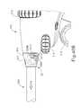
- FIG. 1depicts a side view of an exemplary surgical suturing instrument
- FIG. 2Adepicts top perspective exploded view of a cartridge receiving assembly of the instrument of FIG. 1 ;
- FIG. 2Bdepicts bottom perspective exploded view of the cartridge receiving assembly of FIG. 2A ;
- FIG. 3Adepicts a top perspective view of an exemplary cartridge configured for receipt in the cartridge receiving assembly of FIG. 2A ;
- FIG. 3Bdepicts a bottom perspective view of the cartridge of FIG. 3A ;
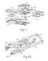
- FIG. 4depicts an exploded view of the cartridge of FIG. 3A ;
- FIG. 5Adepicts a perspective view of a drive assembly of the cartridge of FIG. 3A , with the drive assembly at one end of its stroke;
- FIG. 5Bdepicts a perspective view of the drive assembly of FIG. 5A , with the drive assembly at mid-stroke;
- FIG. 5Cdepicts a perspective view of the drive assembly of FIG. 5A , with the drive assembly at the other end of its stroke;
- FIG. 6depicts a partial plan view of a needle driver of the cartridge of FIG. 3A engaging a needle of the cartridge of FIG. 3A ;
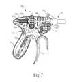
- FIG. 7depicts a side elevational view of the handle assembly of the instrument of FIG. 1 , with a housing half removed to reveal internal components;
- FIG. 8depicts a top plan view of an articulation control assembly of the handle assembly of FIG. 7 ;
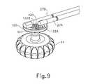
- FIG. 9depicts a perspective view of the articulation control assembly of FIG. 8 ;
- FIG. 10depicts a side elevational view of an articulation rod and follower of the articulation control assembly of FIG. 8 ;
- FIG. 11Adepicts a top plan view of the cartridge receiving assembly of FIG. 2A , the cartridge of FIG. 3A , and the shaft assembly of the instrument of FIG. 1 , with the cartridge receiving assembly aligned with the longitudinal axis of the shaft assembly;
- FIG. 11Bdepicts a top plan view of the cartridge receiving assembly of FIG. 2A , the cartridge of FIG. 3A , and the shaft assembly of the instrument of FIG. 1 , with the cartridge receiving assembly deflected in a first direction away from the longitudinal axis of the shaft assembly by the articulation control assembly of FIG. 8 ;
- FIG. 11Cdepicts a top plan view of the cartridge receiving assembly of FIG. 2A , the cartridge of FIG. 3A , and the shaft assembly of the instrument of FIG. 1 , with the cartridge receiving assembly deflected in a second direction away from the longitudinal axis of the shaft assembly by the articulation control assembly of FIG. 8 ;
- FIG. 12depicts an exemplary alternative handle assembly that may be incorporated into the instrument of FIG. 1 ;
- FIG. 13depicts a side elevational view of the handle assembly of FIG. 12 , with portions of the handle assembly in cross-section, showing the handle in an articulation control state;
- FIG. 14depicts a side elevational view of the handle assembly of FIG. 12 , with portions of the handle assembly in cross-section, showing the handle in a distal head rotation control state;
- FIG. 15Adepicts a side elevational view of the handle assembly of FIG. 12 , with portions of the handle assembly in cross-section, showing the handle in an end effector actuation state, with an actuation rod in a proximal position;
- FIG. 15Bdepicts a side elevational view of the handle assembly of FIG. 12 , with portions of the handle assembly in cross-section, showing the handle in the end effector actuation state, with the actuation rod in a distal position;
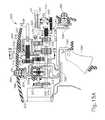
- FIG. 16depicts a cross-sectional view of drive components of the handle assembly of FIG. 12 , taken along line 16 - 16 of FIG. 13 ;
- FIG. 17depicts a cross-sectional view of drive components of the handle assembly of FIG. 12 , taken along line 17 - 17 of FIG. 13 ;
- FIG. 18depicts a cross-sectional view of drive components of the handle assembly of FIG. 12 , taken along line 18 - 18 of FIG. 13 ;
- FIG. 19depicts a cross-sectional view of drive components of the handle assembly of FIG. 12 , taken along line 19 - 19 of FIG. 15A ;
- FIG. 20Adepicts a partial view of a pistol grip of the handle assembly of FIG. 12 ;
- FIG. 20Bdepicts a partial view of the pistol grip of FIG. 20A , with a battery pack removed from a body of the handle assembly;
- FIG. 21depicts a partial view of a pistol grip of the handle assembly of FIG. 12 incorporating a larger battery pack
- FIG. 22depicts a perspective view of an exemplary alternative surgical suturing instrument
- FIG. 23depicts a perspective view of the instrument of FIG. 22 , with a shaft assembly removed from the handle assembly;
- FIG. 24depicts a perspective view of the handle assembly of FIG. 23 ;
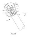
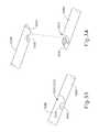
- FIG. 25depicts a perspective view of a proximal end of the shaft assembly of FIG. 23 ;
- FIG. 26depicts an exploded view of actuation shafts of the instrument of FIG. 22 ;
- FIG. 27depicts a perspective view of the actuation shafts of FIG. 26 joined together
- FIG. 28depicts a perspective view of another exemplary alternative surgical suturing instrument
- FIG. 29depicts a perspective view of the instrument of FIG. 28 , with a shaft assembly removed from the handle assembly;
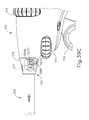
- FIG. 30depicts a perspective view of the handle assembly of FIG. 29 ;
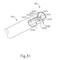
- FIG. 31depicts a perspective view of a proximal portion of the shaft assembly of FIG. 29 ;
- FIG. 32depicts a perspective view of actuation shafts of the instrument of FIG. 28 ;
- FIG. 33depicts a perspective view of head drive shafts of the actuation shafts of FIG. 32 ;
- FIG. 34depicts an exploded view of the head drive shafts of FIG. 33 ;
- FIG. 35depicts a perspective view of the proximal end of a distal head drive shaft of the head drive actuation shafts of FIG. 33 ;
- FIG. 36depicts a perspective view of the distal end of a proximal head drive shaft of the head drive actuation shafts of FIG. 33 ;
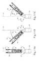
- FIG. 37depicts a perspective view of the proximal end of a distal articulation drive shaft of the actuation shafts of FIG. 32 ;
- FIG. 38depicts a perspective view of the distal end of a proximal articulation drive shaft of the actuation shafts of FIG. 32 ;
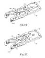
- FIG. 39Adepicts a partial side elevational view of the instrument of FIG. 28 , with portions of the shaft and handle assemblies cut away to reveal internal components, with the shaft assembly separated from the handle assembly;
- FIG. 39Bdepicts a partial side elevational view of the instrument of FIG. 28 , with portions of the shaft and handle assemblies cut away to reveal internal components, with the shaft assembly at a first stage of insertion into the handle assembly;
- FIG. 39Cdepicts a partial side elevational view of the instrument of FIG. 28 , with portions of the shaft and handle assemblies cut away to reveal internal components, with the shaft assembly at a second stage of insertion into the handle assembly;
- FIG. 39Ddepicts a partial side elevational view of the instrument of FIG. 28 , with portions of the shaft and handle assemblies cut away to reveal internal components, with the shaft assembly fully coupled with the handle assembly;
- FIG. 40Adepicts a partial side elevational view of the instrument of FIG. 28 , with portions of the shaft and handle assemblies cut away to reveal internal components, with a button of the handle assembly depressed to initiate decoupling of the shaft assembly from the handle assembly;
- FIG. 40Bdepicts a partial side elevational view of the instrument of FIG. 28 , with portions of the shaft and handle assemblies cut away to reveal internal components, with the shaft assembly being pulled distally away from the handle assembly to decouple the shaft assembly from the handle assembly.
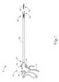
- FIG. 1illustrates an example of a surgical suturing instrument ( 2 ).
- Instrument ( 2 )comprises a handle assembly ( 10 ), an elongate shaft ( 20 ), and a cartridge receiving assembly ( 50 ), which is operable to receive a needle applier cartridge ( 30 ).
- Shaft ( 20 )has a proximal end ( 21 ), a distal end ( 22 ), and a longitudinal axis extending therebetween.
- Handle assembly ( 10 )is connected to the proximal end ( 21 ) of the shaft ( 20 ).
- handle assembly ( 10 )is a manual pistol grip handle.
- Handle assembly ( 10 )could also take the form of a robotic interface, such as a DAVINCI puck, or a housing comprising gears or pulleys, servomechanisms, and the like.
- Needle applier cartridge ( 30 )is connected to the distal end ( 22 ) of shaft ( 20 ) via cartridge receiving assembly ( 50 ). Needle applier cartridge ( 30 ) is operable to rotate an arced needle in a circular path enabling a surgeon to selectively apply sutures.
- needle applier cartridge ( 30 )is integral with shaft ( 20 ) and handle assembly ( 10 ) as a unitary disposable instrument intended for a single surgical procedure. Needle applier cartridge ( 30 ) may also be integral with shaft ( 20 ) and handle assembly ( 10 ) as a reusable instrument.
- needle applier cartridge ( 30 )may be provided in a disposable cartridge body ( 90 ) and shaft ( 20 ) includes cartridge receiving assembly ( 50 ) to releasably hold cartridge body ( 90 ).
- shaft ( 20 ) and handle assembly ( 10 )may also be disposable or reusable. Versions with reusable components are intended to be cleaned, sterilized, and reused for a multiple surgical procedures, and may include a flush port ( 18 ) to facilitate cleaning.
- the preferable life cycle of a reusable instrumentis at least 50 operations, more preferably at least 150 operations, and most preferably at least 200 operations.
- Reusable componentsmay be built using materials that can withstand autoclave sterilization temperatures of at least 135 degrees Celsius, although low temperature materials can also be used with low temperature sterilization techniques known in the art.
- a first input ( 12 ), shown here as a trigger that pivots between opened and closed positions,may be used to selectively actuate needle applier cartridge ( 30 ).
- the triggermay be spring biased to return the trigger to its open position.
- a second input ( 14 ), shown here as a rotary knob,may be used to selectively articulate shaft ( 20 ).
- a third input ( 16 ), shown here as a rotary knob,may be used to selectively rotate needle applier cartridge ( 30 ) about shaft ( 20 ).
- the number, type, configuration, and operation of inputs ( 12 , 14 , 16 )may vary.
- FIGS. 2A-2Billustrate exploded views of cartridge receiving assembly ( 50 ) of the present example.
- Distal end ( 22 ) of shaft ( 20 )comprises an articulation joint ( 23 ) and a rotational bearing ( 24 ).
- Articulation joint ( 23 )includes a knuckle ( 23 A) that receives pins ( 23 B, 23 C), which are connected to bearing supports ( 24 B, 23 C).
- pins ( 23 B, 2 C)define the pivoting axis for articulation joint ( 23 ), enabling cartridge receiving assembly ( 50 ) to articulate left and right relative the shaft ( 20 ), away from the longitudinal axis defined by shaft ( 20 ).
- Rods ( 27 A, 27 B)are operably connected to articulation joint ( 23 ).
- rods ( 27 A, 27 B)extend through shaft ( 20 ), through knuckle ( 23 A), and connect to pins ( 29 A, 29 B) on bearing support ( 24 C).
- Rods ( 27 A, 27 B)are operatively connected to rotary knob ( 14 ) to opposingly push and pull rods ( 27 A, 27 B).
- rotary knob ( 14 )is operable to drive rods ( 27 A, 27 B) at the same time in opposite longitudinal directions, such that rod ( 27 A) will translate distally while rod ( 27 B) translates proximally; and such that rod ( 27 B) will translate distally while rod ( 27 A) translates proximally. Because pins ( 29 A, B) are laterally spaced from the pivoting axis, the simultaneous push and pull action will in turn articulate cartridge receiving assembly ( 50 ) about joint ( 23 ) relative to shaft ( 20 ).
- Rotational bearing ( 24 )is positioned distal to articulation joint ( 23 ).
- Bearing ( 24 )includes a circumferential flange ( 24 A) that is captured between the bearing supports ( 24 B, 24 C) such that the flange ( 24 A) can rotate relative the bearing supports ( 24 B, 24 C) and enabling unbounded rotation of cartridge receiving assembly ( 50 ) relative shaft ( 20 ) about the longitudinal axis defined by shaft ( 20 ).
- a drive rod ( 28 )extends through shaft ( 20 ).
- drive rod ( 28 )comprises a proximal rigid portion ( 28 A) and a distal bendable portion ( 28 B) that are fixedly connected to one another. Bendable portion ( 28 B) extends through articulation joint ( 23 ) and through bearing ( 24 ); distal end ( 28 C) is fixedly connected to a mount ( 49 ) on a rack ( 45 ).
- Rack ( 45 )reciprocates longitudinally in lower jaw ( 51 ) with followers ( 45 A, 45 B, 45 C, 45 D) constrained in tracks ( 55 A, 55 B, 55 C, 55 D), respectively.
- Tracks ( 55 A, 55 B, 55 C, 55 D)open through lower jaw ( 51 ), providing fluid passages to the internal components within the lower jaw ( 51 ), thus facilitating easier cleaning.
- a pinion ( 47 )is mounted to lower jaw ( 51 ) by the pin ( 46 ) in the rack ( 45 ) such that longitudinal reciprocation of the rack ( 45 ) is converted into rotational reciprocation of pinion ( 47 ).
- a key ( 48 )communicates the reciprocating rotation to a rotary input ( 94 ) in cartridge body ( 90 ), which in turn actuates needle applier cartridge ( 30 ).
- Drive rod ( 28 )is operatively connected to first input ( 12 ) and to third input ( 16 ). Actuation of first input ( 12 ) will impart axial push and pull loads on drive rod ( 28 ) to longitudinally reciprocate rack ( 45 ) and thereby actuate needle applier cartridge ( 30 ). Actuation of third input ( 16 ) will impart a rotational load on drive rod ( 28 ) thus rotating cartridge receiving assembly ( 50 ) about bearing ( 24 ) relative to shaft ( 20 ). Accordingly, a single drive rod ( 28 ) operates to both actuate needle applier cartridge ( 30 ) as well as control distal rotation of needle applier cartridge ( 30 ) about the longitudinal axis of shaft ( 20 ). By consolidating dual functions with a single drive rod ( 28 ), the number of components is reduced, and more space is provided in the shaft ( 20 ), which may make the device less expensive to manufacture and easier to clean.
- Cartridge receiving assembly ( 50 )is dimensioned and adapted to receive and hold cartridge body ( 90 ).
- cartridge receiving assembly ( 50 ) of this examplehas upper and lower jaws ( 56 , 51 ) that are operable to transition between an open configuration and a closed configuration. In the closed configuration, jaws ( 56 , 51 ) are operable to receive and retain cartridge body ( 90 ). In the closed configuration, jaws ( 56 , 51 ) are operable to release cartridge body ( 90 ).
- lower jaw ( 51 )is stationary and upper jaw ( 56 ) pivots. Alternatively, the arrangement could be reversed, or in some versions both jaws ( 56 , 51 ) could pivot.
- Lower jaw ( 51 )has two laterally offset longitudinal rails ( 52 ) that are dimensioned and adapted to receive cartridge body ( 90 ). Rails ( 52 ) help longitudinally align cartridge body ( 90 ) in cartridge receiving assembly ( 50 ) and laterally retain cartridge body ( 90 ) in jaws ( 51 , 56 ). Upper jaw ( 56 ) pivots relative lower jaw ( 51 ) about a pin ( 53 ) that is received in holes ( 57 ). A tooth ( 59 ) is resiliently oriented downwardly from upper jaw ( 56 ) toward lower jaw ( 51 ) with a ramped distal face and a stepped proximal face.
- Tooth ( 59 )is dimensioned and adapted to latch with cartridge body ( 90 ) and longitudinally retain cartridge body ( 90 ) in jaws ( 51 , 56 ). Tooth ( 59 ) deflects by virtue of a resilient cantilevered arm extending proximally from the distal end of upper jaw ( 56 ). In this example, tooth ( 59 ) and the cantilevered arm are monolithic with upper jaw ( 56 ), thus reducing the number of components and moving pieces, which may make the device less expensive to manufacture and easier to clean.
- a button ( 60 )is operable to open and close jaws ( 51 , 56 ). While button ( 60 ) could be placed on or near the handle assembly ( 10 ) in some versions, in this example button ( 60 ) is positioned adjacent cartridge receiving assembly ( 50 ), which eliminates a linkage in shaft ( 20 ) thus creating space in shaft ( 20 ) and making the device less expensive and easier to clean.
- the action of button ( 60 )may vary, but in this example button ( 60 ) pivots relative to lower jaw ( 51 ) about a pin ( 63 ) that is received hole ( 61 ).
- a follower ( 62 )is received by cam slots ( 54 , 58 ).
- Pivoting button ( 60 ) proximallywill open jaws ( 51 , 56 ), while pivoting button ( 60 ) distally will close jaws ( 51 , 56 ).
- a spring ( 64 )engages and biases button ( 60 ) distally. By pulling button ( 60 ) proximally, follower ( 62 ) will drive cam slot ( 58 ) to open upper jaw ( 56 ). When button ( 60 ) is released, spring ( 64 ) will resiliently drive button ( 60 ) distally to close upper jaw ( 56 ).
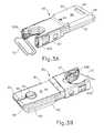
- FIGS. 3A-3Billustrate cartridge body ( 90 ) of the present example in greater detail.
- a lower face ( 91 ) of cartridge body ( 90 )is adapted to engage lower jaw ( 51 ); and an upper face ( 96 ) to engage upper jaw ( 56 ).
- Poke-yoke features on cartridge body ( 90 )prevent improper insertion of cartridge body ( 90 ) into cartridge receiving assembly ( 50 ), but also contribute to the aesthetic appearance of cartridge body ( 90 ).
- lower face ( 91 )has a pair of longitudinal notched shoulders ( 92 ) that are dimensioned to interface and mate with rails ( 52 ).
- notched shoulders ( 92 )are shaped as a stepped rabbet, but a variety of other aesthetic shapes could also be employed such as chamfers and radii.
- upper face ( 96 )is asymmetrical relative lower face ( 91 ) and lacks shoulder notches, so upper face ( 96 ) would interfere with rails ( 52 ) if cartridge body ( 90 ) were inserted upside-down in cartridge receiving assembly ( 50 ).
- the geometry of a proximal face ( 98 ) of cartridge body ( 90 )is vertically asymmetrical and thus prevents cartridge body ( 90 ) from being inserted upside-down between jaws ( 51 , 56 ).
- proximal face ( 98 )comprises a curved surface that gently transitions to upper face ( 96 ), which matches similar geometry in cartridge receiving assembly ( 50 ); while the transition to lower face ( 91 ) has a tighter radius.
- a variety of other asymmetrical aesthetic geometriescould also be employed that could contribute to the visual appearance and/or poke-yoke aspects of cartridge body ( 90 ).
- Arms ( 93 A, 93 B)define a generally U-shaped distal end on cartridge body ( 90 ).
- a slot ( 95 ) and rotary input ( 94 )are aligned and dimensioned to receive the key ( 48 ) while cartridge body ( 90 ) is being slid into cartridge receiving assembly ( 50 ).
- a step ( 99 )aligns with and receives tooth ( 59 ) to latch cartridge body ( 90 ) in cartridge receiving assembly ( 50 ).
- Key ( 48 )also aligns with rotary input ( 94 ), thereby providing a torsional interface that rotationally couples pinion ( 47 ) and rotary input ( 94 ).
- the needle ( 70 )exits arm ( 93 A) and enters arm ( 93 B).
- cartridge body ( 90 )further comprises a lower body ( 81 ), an upper body ( 82 ), a needle ( 70 ), and a needle cover ( 83 ).
- Needle driver ( 86 ), rotary input ( 94 ), and a link ( 85 )are captured between lower body ( 81 ) and upper body ( 82 ).
- Bodies ( 81 , 82 )may be attached to one another using a variety of known techniques, including welds, pins, adhesives, and the like to form cartridge body ( 90 ).
- Needle ( 70 )has a leading end ( 71 ) and a length of suture ( 73 ) extending from the trailing end ( 72 ).
- Needle ( 70 )orbits in a circular path defined by a needle track ( 84 ) and between arms ( 93 A, 93 B). Needle ( 70 ) includes notches ( 74 ) that are configured to facilitate engagement between needle driver ( 86 ) and needle ( 70 ). Needle ( 70 ) is captured in needle track ( 84 ) by needle cover ( 83 ). A cage ( 87 ) slides over bodies ( 81 , 82 ) and needle cover ( 83 ) to attach needle cover ( 83 ) against lower body ( 81 ).
- FIGS. 5A-5Cillustrate an example of a drive stroke of the transmission in cartridge body ( 90 ) for driving needle ( 70 ) in a circular, orbital path.
- Needle driver ( 86 )rides in a carrier track ( 88 ) and extends into needle track ( 84 ) to engage and drive needle ( 70 ).
- a link ( 85 )connects rotary input ( 94 ) to needle driver ( 86 ).
- FIG. 5Ashows needle driver ( 86 ) positioned at one end of its stroke in carrier track ( 88 ). As shown in FIG.
- Needle driver ( 86 )is disengaged from needle ( 70 ) during the return stroke until needle driver ( 86 ) reaches the end of the return stroke. Needle driver ( 86 ) will re-engage needle ( 86 ) upon completing the return stroke. Thus, a sequence of drive and return strokes will rotate the needle ( 70 ) in a circular path.
- FIG. 6illustrates a detailed view of needle driver ( 86 ) engaging needle ( 70 ).
- Needle driver ( 86 )comprises a carrier ( 86 A) and a driver ( 86 B).
- Carrier ( 86 A)is dimensioned to slideably fit in carrier track ( 88 ).
- Driver ( 86 B)is attached to carrier ( 75 ) and is operative to engage needle ( 70 ) at an oblique angle.
- Leftward movement of needle driver ( 86 )will cause driver ( 86 B) to engage proximal notch ( 74 ) of needle ( 70 ) during the drive stroke.
- needle ( 70 )will slide in needle track ( 84 ) in unison with needle driver ( 86 ). Due to the oblique angle, rightward movement of needle driver ( 86 ) will disengage driver ( 86 B) from proximal notch ( 74 ) of needle ( 70 ) and slide over the stationary needle ( 70 ) during the return stroke.
- needle driver ( 86 )when first input ( 12 ) is depressed, closing the trigger, needle driver ( 86 ) will be actuated through its drive stroke where it orbits along an angular range of motion at least about 180 degrees counterclockwise to a driven position as shown in FIG. 5C .
- driver ( 86 B)engages proximal notch ( 74 ) and will in unison rotate needle ( 70 ) about 180 degrees along an orbital path to its extended position. Needle ( 70 ) will span across arms ( 93 A, 93 B) between exit port ( 95 ) and entrance port ( 97 ). Tissue interposed between arms ( 93 A, 93 B) will be pierced by leading end ( 71 ) of needle ( 70 ).
- needle driver ( 86 )When first input ( 12 ) is released and the spring return opens the trigger, needle driver ( 86 ) reciprocates through its return stroke where it orbits along an angular range of motion about 180 degrees clockwise back to the return position shown in FIG. 5A . During the return stroke, driver ( 86 B) slides over the needle ( 70 ). Driver ( 86 B) is then adjacent the distal notch ( 74 ). When first input ( 12 ) is depressed again closing the trigger, needle driver ( 86 ) will again be actuated through its drive stroke where it orbits along an angular range of motion about 180 degrees counterclockwise to the driven position as shown in FIG. 5C .
- driver ( 86 B)engages distal notch ( 74 ) and will in unison drive needle ( 70 ) orbitally along an angular range of motion about 180 degrees back to its retracted position. Suture ( 73 ) will follow needle ( 70 ) and be threaded through the pierced tissue.
- needle driver ( 86 )again reciprocates through its return stroke where it orbits along an angular range of motion about 180 degrees clockwise back to its returned position as shown in FIG. 5A .
- driver ( 86 B)slides over needle ( 70 ).
- needle ( 70 )is driven in a complete circular path spanning an angular range of 360° in response to first input ( 12 ) being actuated twice. The sequence may be repeated as needed by the surgeon to achieve the desired suturing task.
- Rotary knob ( 14 )is operable to selectively articulate joint ( 23 ).
- Rotary knob ( 14 )rotates in a plane spaced below and generally parallel with shaft ( 20 ).
- An axle ( 121 )connects rotary knob ( 14 ) to a disk ( 120 ) in shroud ( 11 ) that also rotates in a plane generally parallel with the shaft ( 20 ).
- disk ( 120 )comprises first and second cam slots ( 122 A, 122 B), each having a length with angular and radial components.
- the cam slots ( 122 A, 122 B)are two identical spirals offset 180 degrees from one another.
- Each cam slot ( 122 A, 122 B)has an angular span between about 220 degrees and about 300 degrees, with their angular spans overlapping one another. Cam slots ( 122 A, 122 B) also increase their distance from the center of disk ( 120 ) in the same angular direction. Each cam slot ( 122 A, 122 B) has a radial span of about 0.100 inches and about 0.155 inches. Of course, the configuration and dimensions of cam slots ( 122 A, 122 B) may alternatively differ from the foregoing.
- Cam slot ( 122 A)receives a cam follower ( 124 A) on a distal half of disk ( 120 ), and cam slot ( 122 B) receives a cam follower ( 124 B) on the proximal half of disk ( 120 ).
- Followers ( 124 A, 124 B)extend downwardly and generally normal from the proximal ends of rods ( 27 A, 27 B), respectively. In this example, followers ( 124 A, 124 B) are medially offset from longitudinal axes of the respective drive rod ( 27 A, 27 B).
- Rods ( 27 A, 27 B)are constrained to slide axially, so counterclockwise rotation of disk ( 120 ) moves rod ( 27 B) proximally and simultaneously moves rod ( 27 A) distally to articulate joint ( 23 ) to the left of the longitudinal axis (LA) of shaft ( 20 ), as shown in the transition from FIG. 11A to FIG. 11B .
- clockwise rotation of disk ( 120 )moves rod ( 27 B) distally and simultaneously moves rod ( 27 A) proximally, thereby articulating joint ( 23 ) to the right of the longitudinal axis (LA) of shaft ( 20 ), as shown in the transition from FIG. 11A to FIG. 11C .
- Cam slots ( 122 A, 122 B)each define a tangent axis ( 126 A, 126 B) where cam slot ( 122 A, 122 B) is engaged by the respective cam followers ( 124 A, 124 B).
- the tangent axes ( 126 A, 126 B)may be substantially normal to the longitudinal axes of rods ( 27 A, 27 B) so axial push and pull loads on rods ( 27 A, 27 B) introduced by side loads on cartridge receiving assembly ( 50 ) will not cause disk ( 120 ) to rotate. Accordingly, joint ( 23 ) will remain locked at its articulated angle.
- Frictional interfaces or detentsmay be added to further prevent unintentional articulation, such as between followers ( 124 A, 124 B) and cam slots ( 122 A, 122 B), between disk ( 120 ) and shroud ( 11 ), between axle ( 121 ) and shroud ( 11 ), and/or in any other suitable fashion.
- FIG. 9illustrates an alternative example of an articulation control.
- a plurality of detents ( 125 )are positioned along cam slots ( 122 A, 122 B).
- detents ( 125 )may provide feedback to the surgeon indicating various angular positions of needle applier cartridge ( 30 ) relative shaft ( 20 ).
- Detents ( 125 )may be indexed to correspond to one or more predetermined articulation angles, such as 0 degrees, 15 degrees, 45 degrees, and the like; or detents ( 125 ) may be equally distributed along cam slots ( 122 A, 122 B). Larger detents ( 127 ) may be located at the ends of the cam slots ( 122 A, 122 B).
- Detents ( 125 )open to the top surface of disk ( 120 ), but only partially extend into cam slots ( 122 A, 122 B). As shown in FIG. 10 , follower ( 124 ) extends downwardly from articulation rod ( 27 ).
- Follower ( 124 )includes a straight portion ( 124 C) that closely fits in cam slots ( 122 A, 122 B) and a radius portion ( 124 D) dimensioned to be received by detents ( 125 ).
- radius portion ( 124 D)will raise and lower into detents ( 125 ) but the straight portion ( 124 C) will follow and remain engaged in the cam slots ( 122 A, B).
- rod ( 27 )will be biased downwardly toward disk ( 120 ) to provide a tactile and/or audible “click” as radius portion ( 124 D) engages detents ( 125 ).
- needle applier cartridge ( 30 )may fail to actuate fully. This may occur when an operator fails to fully manually actuate first input ( 12 ), which may result in needle ( 70 ) not being fully actuated through its drive stroke.
- motorizing the actuating of needle applier cartridge ( 30 )may ensure that needle ( 70 ) is fully driven through tissue interposed between arms ( 93 A, 93 B).
- handle assembly ( 10 )may include a transmission assembly that may be shifted between three states by a double acting solenoid or some other shifting mechanism, allowing a single motor to be used to drive actuation of needle applier cartridge ( 30 ), articulation of shaft ( 20 ), and/or to rotation of needle applier cartridge ( 30 ).
- handle assembly ( 10 )may include a transmission assembly that may be shifted between three states by a double acting solenoid or some other shifting mechanism, allowing a single motor to be used to drive actuation of needle applier cartridge ( 30 ), articulation of shaft ( 20 ), and/or to rotation of needle applier cartridge ( 30 ).
- Various examples of how instrument ( 2 ) may be reconfigured to incorporate a motorwill be described in greater detail below; while other examples will be apparent to those of ordinary skill in the art according to the teachings herein. It should be understood that the examples described below may function substantially similar to instrument ( 2 ) described above. In particular, the surgical suturing instruments described below may be used to suture tissue.
- FIGS. 12-19illustrate an exemplary handle assembly ( 200 ) that is operable for use with instrument ( 2 ) discussed above.
- Handle assembly ( 200 )is connected to the proximal end ( 21 ) of the shaft ( 20 ).
- handle assembly ( 200 )includes a motor ( 202 ) and a transmission assembly ( 210 ).
- motor ( 202 )is configured to drive actuation of needle applier cartridge ( 30 ), articulation of shaft ( 20 ), and rotation of needle applier cartridge ( 30 ) via transmission assembly ( 210 ).
- transmission assembly ( 210 )may be shifted between three states by a double acting solenoid ( 204 ), so as to allow motor ( 202 ) to be used to drive actuation of needle applier cartridge ( 30 ), articulation of shaft ( 20 ), and rotation of needle applier cartridge ( 30 ).
- handle assembly ( 200 )may additionally include a variety of manual actuators including but not limited to a manual pistol grip handle, a scissor grip handle, a syringe grip handle, endoscopic rotary knobs, and the like.
- Handle assembly ( 200 )could also take the form of a robotic interface, such as a DAVINCI puck, or a housing comprising gears or pulleys, servomechanisms, and the like.
- the shaft ( 20 ), cartridge receiving assembly ( 50 ), and cartridge ( 30 ) that are used with handle assembly ( 200 )may be identical to the shaft ( 20 ), cartridge receiving assembly ( 50 ), and cartridge ( 30 ) that are used with handle assembly ( 10 ) as described above.
- Motor ( 202 )includes a drive shaft ( 206 ). Activation of motor ( 202 ) causes rotation of drive shaft ( 206 ).
- Drive shaft ( 206 )includes a gear ( 207 ) having a plurality of teeth angularly disposed about and radially extending from an exterior surface of gear ( 207 ).
- Transmission assembly ( 210 )includes an axle ( 212 ).
- Axle ( 212 )is rotatably secured within and to handle assembly ( 200 ) such that axle ( 212 ) is operable to rotate within and relative to handle assembly ( 200 ).
- Axle ( 212 )includes a pair of gears ( 214 , 216 ) that are fixedly secured to axle ( 212 ).
- Gear ( 214 )includes a plurality of teeth that are angularly disposed about and radially extending from an exterior surface of gear ( 214 ).
- Gear ( 216 )includes a plurality of teeth that are angularly disposed about and radially extending from an exterior surface of gear ( 216 ).
- the teeth of gear ( 207 ) of drive shaft ( 206 )are engaged with the teeth of first gear ( 214 ) of axle ( 212 ) such that rotation of drive shaft ( 206 ) causes concurrent rotation of axle ( 212 ).
- Solenoid ( 204 )includes a piston ( 220 ). Piston ( 220 ) is rotatably and slidably secured within and to handle assembly ( 200 ) such that piston ( 212 ) is operable to rotate and translate within and relative to handle assembly ( 200 ). A magnet ( 222 ) is fixedly secured to a proximal end of piston ( 220 ) such that translation of magnet ( 222 ) will cause translation of piston ( 220 ). Solenoid ( 204 ) further includes a pair of wire coils ( 224 , 226 ) positioned about the proximal end of piston ( 220 ) such that piston ( 220 ) is operable to rotate and translate within and relative to wire coils ( 224 , 226 ).
- Magnet ( 222 ) of piston ( 220 )is positioned between wire coils ( 224 , 226 ). Magnet ( 222 ), and as a result piston ( 220 ), is biased toward an intermediate position ( FIGS. 15A and 15B ) via a pair of coil springs ( 225 , 227 ), which are coaxially positioned about piston ( 220 ) and between wire coils ( 224 , 226 ) and magnet ( 222 ).
- wire coils ( 224 , 226 )are configured to cause proximal and distal translation of magnet ( 222 ), thereby causing proximal and distal translation of piston ( 220 ).
- wire coil ( 224 )is configured to cause proximal translation of magnet ( 222 ), and as a result piston ( 220 ) ( FIG. 14 ); and when an electric current is provided through wire coil ( 226 ), wire coil ( 226 ) is configured to cause distal translation of magnet ( 222 ), and as a result piston ( 220 ) ( FIG. 13 ).
- wire coil ( 224 )when an electric current is provided through wire coil ( 224 ), wire coil ( 224 ) is configured to cause distal translation of magnet ( 222 ), and as a result piston ( 220 ) ( FIG. 13 ); and when an electric current is provided through wire coil ( 226 ), wire coil ( 226 ) is configured to cause proximal translation of magnet ( 222 ), and as a result piston ( 220 ) ( FIG. 14 ).
- Piston ( 220 )further includes a plurality of gears ( 230 , 232 , 234 ) that are fixedly secured to piston ( 220 ).
- Gear ( 230 )includes a plurality of teeth angularly disposed about and extending radially from an exterior surface of gear ( 230 ).
- Gear ( 232 )includes a plurality of teeth angularly disposed about and extending radially from an exterior surface of gear ( 232 ).
- Gear ( 234 )includes a plurality of teeth angularly disposed about and extending radially from an exterior surface of gear ( 234 ). As best seen in FIG.
- gear ( 216 ) of axle ( 212 )are engaged with the teeth of gear ( 232 ) of piston ( 220 ) such that rotation of axle ( 212 ) causes concurrent rotation of piston ( 220 ).
- Gear ( 216 ) of axle ( 212 )is of sufficient width such that as piston ( 220 ) and gear ( 232 ) translate between the proximal position ( FIG. 14 ), the intermediate position ( FIGS. 15A and 15B ), and the distal position ( FIG. 13 ), gear ( 232 ) remains engaged with gear ( 216 ) such that rotation of axle ( 212 ) causes concurrent rotation of piston ( 220 ) as piston ( 220 ) translates between the proximal position ( FIG. 14 ), the intermediate position ( FIGS. 15A and 15B ), and the distal position ( FIG. 13 ).
- transmission assembly ( 210 )further includes a threaded member ( 236 ).
- Threaded member ( 236 )is rotatably secured within and to handle assembly ( 200 ) such that threaded member ( 236 ) is operable to rotate within and relative to handle assembly ( 200 ).
- Threaded member ( 236 )includes an integral gear ( 237 ) having a plurality of teeth angularly disposed about and extending radially from an exterior surface of gear ( 237 ). As shown in FIG.
- Transmission assembly ( 210 )further includes a rack ( 240 ).
- Rack ( 240 )is slidably secured within and to handle assembly ( 200 ) such that rack ( 240 ) is operable to translate within and relative to handle assembly ( 200 ).
- Rack ( 240 )includes a plurality of teeth disposed along a length of and extending laterally from rack ( 240 ).
- Rack ( 240 )further includes a threaded bore ( 242 ) configured to matingly receive threading ( 238 ) of threaded member ( 236 ) such that rotation of threaded member ( 236 ) causes translation of rack ( 240 ).
- Disk ( 120 ) of the present exampleincludes a drive shaft ( 244 ), which is rotatably supported in handle assembly ( 200 ). Rotation of drive shaft ( 244 ) causes rotation of disk ( 120 ).
- Drive shaft ( 244 )includes a gear ( 245 ) having a plurality of teeth angularly disposed about and extending radially from an exterior surface of gear ( 245 ). The teeth of gear ( 245 ) are engaged with the teeth of rack ( 240 ) such that translation of rack ( 240 ) causes rotation of drive shaft ( 244 ), thereby causing rotation of disk ( 120 ).
- rods ( 27 A, 27 B)are engaged with disk ( 120 ).
- Transmission assembly ( 210 )further includes another threaded member ( 250 ).
- Threaded member ( 250 )is rotatably secured within and to handle assembly ( 200 ) such that threaded member ( 250 ) is operable to rotate within and relative to handle assembly ( 200 ).
- Threaded member ( 250 )includes a gear ( 251 ) having a plurality of teeth angularly disposed about and extending radially from an exterior surface of gear ( 251 ). As shown in FIG.
- Drive rod ( 28 )includes a sleeve ( 252 ).
- Sleeve ( 252 )is unitarily secured to the proximal end of drive rod ( 28 ) and extends proximally from the proximal end of drive rod ( 28 ).
- Sleeve ( 252 )includes an integral spline feature ( 253 ) and a threaded bore ( 254 ).
- Spline feature ( 253 )includes an angularly spaced array of radially and longitudinally extending splines. Threaded bore ( 254 ) configured to matingly receive threading ( 256 ) of threaded member ( 250 ).
- a spring ( 256 ) positioned about threaded member ( 250 ) and between gear ( 251 ) and sleeve ( 252 )is configured to increase friction between threaded member ( 250 ) and sleeve ( 252 ) by driving the threading of threaded bore ( 254 ) distally against the threading of threaded member ( 250 ).
- drive rod ( 28 )is operable to rotate to thereby cause rotation of needle applier cartridge ( 30 ). It should therefore be understood that with piston ( 220 ) in the proximal position ( FIG. 14 ), motor ( 202 ) is operable to selectively drive rotation of needle applier cartridge ( 30 ).
- Piston ( 220 )further includes a pawl ( 239 ) positioned between gears ( 230 , 232 ). Pawl ( 239 ) is rotatably supported on piston ( 220 ) such that pawl ( 239 ) will translate longitudinally with piston ( 220 ) but not rotate with piston ( 220 ).
- pawl ( 239 )may be secured to piston ( 220 ) by a bushing.
- Handle assembly ( 200 )also includes boss features (not shown) that permit pawl ( 239 ) to translate within handle assembly ( 200 ) but prevent pawl ( 239 ) from rotating within handle assembly ( 200 ). With piston ( 220 ) in the proximal position, pawl ( 239 ) is disengaged from sleeve ( 252 ) such that sleeve ( 252 ) may freely rotate with threaded member ( 250 ).
- pawl ( 239 )is configured to engage the splines of spline feature ( 253 ) of sleeve ( 252 ) so as to prevent rotation of sleeve ( 252 ).
- rotation of threaded member ( 250 )will cause translation of sleeve ( 252 ) due to the threaded engagement between threading ( 256 ) and threaded bore ( 254 ).
- drive rod ( 28 )is operable to translate to thereby cause actuation of needle applier cartridge ( 30 ).
- motor ( 202 )is operable to selectively actuate needle applier cartridge ( 30 ).
- spline feature ( 253 )simultaneously disengages pawl ( 239 ) of piston ( 220 ) and engages a flange ( 209 ) of handle assembly ( 200 ).
- Flange ( 209 )is also configured to prevent rotation of sleeve ( 252 ) when flange ( 209 ) is engaged with spline feature ( 253 ).
- pawl ( 239 ) and flange ( 209 )cooperate to prevent rotation of sleeve ( 252 ) as sleeve ( 252 ) translates relative to handle assembly ( 200 ) through the range of motion shown in FIGS. 15A-15B to actuate needle applier cartridge ( 30 ).
- Motor ( 202 ) and solenoid ( 204 )are in communication with a plurality of operator inputs ( 280 , 282 , 284 ) and a power source (not shown) via a circuit board ( 290 ).
- Operator inputs ( 280 , 282 , 284 )are positioned just like inputs ( 12 , 14 , 16 ) and provide an outward appearance that is similar to that of inputs ( 12 , 14 , 16 ).
- Operator input ( 280 )includes a manually actuated trigger (e.g., similar to first input ( 12 ), etc.) that is operable to selectively activate a switch feature ( 292 ).
- Switch feature ( 292 )is in communication with circuit board ( 290 ).
- circuitry of circuit board ( 290 )is configured such that activation of switch feature ( 292 ) will de-activate solenoid ( 204 ) to allow springs ( 225 , 227 ) to drive piston ( 220 ) into the intermediate position ( FIGS. 15A-15B ); and then activate motor ( 202 ).
- operator input ( 280 )is operable to selectively actuate needle applier cartridge ( 30 ).
- operator input ( 280 ) and switch feature ( 292 )are just merely illustrative examples of features that may be used to actuate needle applier cartridge ( 30 ) via motor ( 202 ).
- Other suitable features that may be used in addition to or in lieu of operator input ( 280 ) and switch feature ( 292 )will be apparent to those of ordinary skill in the art in view of the teachings herein.
- Operator input ( 282 )includes a rotary wheel that is operable to selectively activate a variable resistor feature ( 294 ).
- Variable resistor feature ( 294 )is in communication with circuit board ( 290 ).
- the circuitry of circuit board ( 290 )is configured such that activation of variable resistor feature ( 294 ) will consecutively actuate solenoid ( 204 ) so as to drive piston ( 220 ) into the distal position ( FIG. 13 ); and then activate motor ( 202 ). It should therefore be understood that operator input ( 282 ) is operable to selectively articulate joint ( 23 ).
- operator input ( 282 ) and variable resistor feature ( 294 )are just merely illustrative examples of features that may be used to selectively articulate joint ( 23 ) via motor ( 202 ).
- Other suitable featuresthat may be used in addition to or in lieu of operator input ( 282 ) and variable resistor feature ( 294 ) will be apparent to those of ordinary skill in the art in view of the teachings herein.
- Operator input ( 284 )also includes a rotary wheel that is operable to selectively activate a variable resistor feature ( 296 ).
- Variable resistor feature ( 296 )is in communication with circuit board ( 290 ).
- the circuitry of circuit board ( 290 )is configured such that activation of variable resistor feature ( 296 ) will consecutively actuate solenoid ( 204 ) so as to drive piston ( 220 ) into the proximal position ( FIG. 14 ); and then activate motor ( 202 ). It should therefore be understood that operator input ( 284 ) is operable to selectively rotate needle applier cartridge ( 30 ).
- operator input ( 284 ) and variable resistor feature ( 296 )are just merely illustrative examples of features that may be used to selectively rotate needle applier cartridge ( 30 ) via motor ( 202 ).
- Other suitable featuresthat may be used in addition to or in lieu of operator input ( 284 ) and variable resistor feature ( 296 ) will be apparent to those of ordinary skill in the art in view of the teachings herein.
- operator inputs ( 280 , 282 , 284 )may include a foot actuated pedal in communication with solenoid ( 204 ) and/or motor ( 202 ).
- Other suitable forms that operator inputs ( 280 , 282 , 284 ) may takewill be apparent to those of ordinary skill in the art in view of the teachings herein.
- operator inputs ( 280 , 282 , 284 )may be placed in any appropriate position on or relative to instrument ( 2 ) as will be apparent to one of ordinary skill in the art in view of the teachings herein.
- operator inputs ( 280 , 282 , 284 )may be positioned on any portion of handle assembly ( 200 ).
- operator inputs ( 280 , 282 , 284 )may also be positioned somewhere separately from instrument ( 2 ), which may include locating operator inputs ( 280 , 282 , 284 ) on a separate console or computer. Operator inputs ( 280 , 282 , 284 ) could also be located on a console or device in wireless communication with instrument ( 2 ). Other suitable locations for operator inputs ( 280 , 282 , 284 ) will be apparent to those of ordinary skill in the art in view of the teachings herein.
- handle assembly ( 200 ) of the present examplemay further include a battery pack ( 300 ).
- Battery pack ( 300 )is operable to provide electrical power to a motor ( 202 ) and solenoid ( 204 ).
- Battery pack ( 300 )is removable from handle assembly ( 200 ).
- battery pack ( 300 )may be inserted into a socket ( 310 ) formed in handle assembly ( 200 ). Once battery pack ( 300 ) is fully inserted in socket ( 310 ), latches ( 302 ) of battery pack ( 300 ) may resiliently engage interior features of handle assembly ( 200 ) to provide a snap fit.
- battery pack ( 300 )may have complementary electrical contacts, pins and sockets, and/or other features that provide paths for electrical communication from battery pack ( 300 ) to electrically powered components in handle assembly ( 200 ) when battery pack ( 300 ) is inserted in socket ( 310 ). It should also be understood that, in some versions, battery pack ( 300 ) is unitarily incorporated within handle assembly ( 200 ) such that battery back ( 300 ) cannot be removed from handle assembly ( 200 ). As shown between FIGS.
- different size batteries ( 304 )may be included with battery pack ( 300 ) depending upon an operator's requirements/intended use. For instance, the larger battery pack ( 300 ) shown in FIG. 21 may provide greater power and/or a longer duration of use.
- Such a replaceable shaftmay include an integrated needle applier cartridge such that an operator need only replace the shaft instead of replacing the needle applier cartridge ( 30 ) as described above.
- a replaceable shaftmay removably receive a needle applier cartridge ( 30 ) as described above.
- Such a replaceable shaftmay be used in conjunction with a manually driven handle assembly ( 10 ) as described above (see infra Part I) or in conjunction with a motorized handle assembly ( 200 ) as described above (see infra Part II). It may be desirable to provide such a replaceable shaft so as to provide a disposable/reusable dichotomy.
- the replaceable shaftmay be provided as a disposable component while the handle assembly may be sterilized, reprocessed, reused, etc.
- the handle assemblymay be sterilized, reprocessed, reused, etc.
- FIGS. 22-27illustrate an exemplary alternative surgical suturing instrument ( 400 ).
- Instrument ( 400 )comprises a handle assembly ( 410 ) and an elongate shaft ( 420 ).
- Shaft ( 420 )has a proximal end ( 421 ), a distal end ( 422 ), and a longitudinal axis extending therebetween.
- handle assembly ( 410 )is selectively coupleable to the proximal end ( 421 ) of the shaft ( 420 ).
- handle assembly ( 410 )is a manual pistol grip handle similar to handle assembly ( 10 ).
- Handle assembly ( 410 )could also take the form of a robotic interface, such as a DAVINCI puck, or a housing comprising gears or pulleys, servomechanisms, and the like. It should also be understood that handle assembly ( 410 ) may have motorized actuation features just like handle assembly ( 200 ).
- Shaft ( 420 )includes an integral cartridge receiving assembly ( 450 ) that is configured to receive and actuate a needle applier cartridge ( 30 ) in the same fashion as cartridge receiving assembly ( 50 ) described above.
- Cartridge receiving assembly ( 450 )is positioned at the distal end ( 422 ) of shaft ( 420 ).
- Cartridge receiving assembly ( 450 )is operable actuate a needle applier cartridge ( 30 ) to rotate an arced needle in a circular path enabling a surgeon to selectively apply sutures.
- needle applier cartridge ( 30 )may be provided as a unitary, integral feature of shaft ( 420 ) such that the components of needle applier cartridge ( 30 ) may be integrally combined with components of cartridge receiving assembly ( 450 ).
- Distal end ( 422 ) of shaft ( 420 )further comprises an articulation joint ( 423 ).
- a first input ( 412 ), shown here as a trigger that pivots between opened and closed positions,may be used to selectively actuate a needle applier cartridge ( 30 ) via cartridge receiving assembly ( 450 ).
- the triggermay be spring biased to return the trigger to its open position.
- a second input ( 414 ), shown here as a rotary knob,may be used to selectively articulate cartridge receiving assembly ( 450 ) at articulation joint ( 423 ).
- a third input ( 416 ), shown here as a rotary knob,may be used to selectively rotate cartridge receiving assembly ( 450 ) and an associated cartridge ( 30 ) about the longitudinal axis of shaft ( 420 ).
- the number, type, configuration, and operation of inputs ( 412 , 414 , 416 )may vary.
- shaft ( 420 )is removable from handle assembly ( 410 ).
- a distal end ( 411 ) of handle assembly ( 410 )includes a semi-conical hub ( 415 ).
- proximal end ( 421 ) of shaft ( 420 )includes a mating semi-conical hub ( 425 ).
- shaft ( 420 )is guided along a vertical path (VP) (that is transverse to the longitudinal axis of shaft ( 420 )) toward hub ( 415 ) to thereby couple shaft ( 420 ) with handle assembly ( 410 ).
- VPvertical path
- hubs ( 415 , 425 )are configured to align with one another to form a substantially continuous conical hub.
- a pair of latches ( 426 ) of hub ( 425 )may resiliently engage a pair of sockets ( 413 ) formed in hub ( 415 ) to provide a snap fit between shaft ( 420 ) and handle assembly ( 410 ).
- the operatormay disengage latches ( 426 ) of hub ( 425 ) from sockets ( 413 ) of hub ( 415 ) then remove shaft ( 420 ) from handle assembly ( 410 ) along the same vertical path (VP) used to couple shaft ( 420 ) with handle assembly ( 410 ).
- VPvertical path
- a pair of articulation rods ( 427 A, 427 B)are operatively connected to articulation joint ( 423 ).
- Rods ( 427 A, 427 B)are shown in FIGS. 25-27 .
- rods ( 427 A, 427 B)are slidably disposed within shaft ( 420 ) such that rods ( 427 A, 427 B) are configured to translate longitudinally within and relative to shaft ( 420 ).
- Proximal ends of rods ( 427 A, 427 B)extend from proximal end ( 421 ) of shaft ( 420 ).
- a pair of mating articulation rods ( 427 C, 427 D)extends through handle assembly ( 410 ) such that a distal end of each rod ( 427 C, 427 D) extends from a distal end of handle assembly ( 410 ).
- Rods ( 427 C, 427 D)are operatively connected to rotary knob ( 414 ) to opposingly push and pull rods ( 427 C, 427 D).
- rotary knob ( 414 )is operable to drive rods ( 427 C, 427 D) at the same time in opposite longitudinal directions, such that rod ( 427 C) will translate distally while rod ( 427 D) translates proximally; and such that rod ( 427 C) will translate distally while rod ( 427 D) translates proximally.
- rods ( 427 A, 427 B) of shaft ( 420 )are configured to couple respectively with rods ( 427 C, 427 D) of handle assembly ( 410 ) such that rod ( 427 A) will translate concurrently with rod ( 427 C) and such that rod ( 427 B) will translate concurrently with rod ( 427 D). Accordingly, rods ( 427 A, 427 B, 427 C, 427 D) operate to articulate shaft ( 420 ) in the same fashion in which rods ( 27 A, 27 B) articulate shaft ( 20 ) as described above.
- a drive rod ( 428 A)is slidably disposed within shaft ( 420 ) such that drive rod ( 428 A) is configured to translate longitudinally within and relative to shaft ( 420 ).
- a proximal end of rod ( 428 A)extends from proximal end ( 421 ) of shaft ( 420 ).
- a mating drive rod ( 428 B)extends through handle assembly ( 410 ) such that a distal end of drive rod ( 428 B) extends from the distal end of handle assembly ( 410 ).
- Drive rod ( 428 B)is operatively connected to first input ( 412 ) and to third input ( 416 ).
- first input ( 412 )will impart axial push and pull loads on drive rod ( 428 B) to thereby actuate a needle applier cartridge ( 30 ) as described above with reference to instrument ( 2 ) via cartridge receiving assembly ( 450 ).
- Actuation of third input ( 416 )will impart a rotational load on drive rod ( 428 B) thus rotating needle applier cartridge ( 30 ) relative to shaft ( 420 ) as described above with reference to instrument ( 2 ) via cartridge receiving assembly ( 450 ).
- drive rod ( 428 A) of shaft ( 420 )is configured to couple with drive rod ( 428 B) of handle assembly ( 410 ) such that drive rod ( 428 A) will translate and rotate concurrently with drive rod ( 428 B). Accordingly, drive rods ( 428 A, 428 B) operate to both actuate a needle applier cartridge ( 30 ) via cartridge receiving assembly ( 450 ) as well as control distal rotation of cartridge receiving assembly ( 450 ) about the longitudinal axis of shaft ( 420 ).
- the proximal ends of rods ( 427 A, 427 B, 428 A) of shaft ( 420 )include T-shaped projections ( 450 A, 450 B, 450 C).
- the distal ends of rods ( 427 C, 427 D, 428 B) of handle assembly ( 410 )include T-shaped slots ( 451 A, 451 B, 451 C) formed therein.
- Projections ( 450 A, 450 B, 450 C) of rods ( 427 A, 427 B, 428 A)are configured to mate with and engage slots ( 451 A, 451 B, 451 C) of rods ( 427 C, 427 D, 428 B).
- This engagement between projections ( 450 A, 450 B, 450 C) and slots ( 451 A, 451 B, 451 C)is configured to communicate translation and rotation of rods ( 427 C, 427 D, 428 B) of handle assembly ( 410 ) to rods ( 427 A, 427 B, 428 A) of shaft ( 420 ).
- hub ( 425 )includes a set of sleeves ( 460 , 462 , 464 ) through which rods ( 427 A, 427 B, 428 A) extend.
- Sleeves ( 460 , 462 , 464 )remain stationary relative to shaft ( 420 ) while rods ( 427 A, 427 B, 428 A) are translatable within shaft ( 420 ).
- Sleeves ( 460 , 462 , 464 )are configured to prevent mating of rods ( 427 A, 427 B, 428 B) of shaft ( 420 ) with rods ( 427 C, 427 D, 428 B) of handle assembly ( 410 ) unless rods ( 427 A, 427 B, 428 A) are in a “home” position (i.e., a proximal position) relative to shaft ( 420 ).
- any rod ( 427 A, 427 B, 428 A)is positioned distal to the home position, the corresponding sleeve ( 460 , 462 , 464 ) will prevent T-shaped projection ( 450 A, 450 B, 450 C) of the distally positioned rod ( 427 A, 427 B, 428 A) from coupling with the complementary slot ( 451 A, 451 B, 451 C) of the corresponding rod ( 427 C, 427 D, 428 B).
- shaft ( 420 ) and/or handle assembly ( 410 )may be provided as being disposable or reusable. Versions with reusable components are intended to be cleaned, sterilized, and reused for multiple surgical procedures, and may include a flush port (not shown) to facilitate cleaning.
- the preferable life cycle of a reusable instrumentmay be at least 50 operations, more particularly at least 150 operations, or more particularly at least 200 operations.
- Reusable componentsmay be built using materials that can withstand autoclave sterilization temperatures of at least 135 degrees Celsius, although low temperature materials can also be used with low temperature sterilization techniques known in the art.
- FIGS. 28-40Billustrate another exemplary alternative surgical suturing instrument ( 500 ).
- Instrument ( 500 )comprises a handle assembly ( 510 ) and an elongate shaft ( 520 ).
- Shaft ( 520 )has a proximal end ( 521 ), a distal end ( 522 ), and a longitudinal axis extending therebetween.
- handle assembly ( 510 )is selectively coupleable to the proximal end ( 521 ) of the shaft ( 520 ).
- handle assembly ( 510 )is a manual pistol grip handle.
- Handle assembly ( 510 )could also take the form of a robotic interface, such as a DAVINCI puck, or a housing comprising gears or pulleys, servomechanisms, and the like. It should also be understood that handle assembly ( 510 ) may have motorized actuation features just like handle assembly ( 200 ).
- Shaft ( 520 )includes an integral cartridge receiving assembly ( 550 ) that is configured to receive and actuate a needle applier cartridge ( 30 ) in the same fashion as cartridge receiving assembly ( 50 ) described above.
- Cartridge receiving assembly ( 550 )is positioned at the distal end ( 522 ) of shaft ( 520 ).
- Cartridge receiving assembly ( 550 )is operable actuate a needle applier cartridge ( 30 ) to rotate an arced needle in a circular path enabling a surgeon to selectively apply sutures.
- needle applier cartridge ( 30 )may be provided as a unitary, integral feature of shaft ( 520 ) such that the components of needle applier cartridge ( 30 ) may be integrally combined with components of cartridge receiving assembly ( 550 ).
- Distal end ( 522 ) of shaft ( 520 )further comprises an articulation joint ( 523 ).
- a first input ( 512 ), shown here as a trigger that pivots between opened and closed positions,may be used to selectively actuate a needle applier cartridge ( 30 ) via cartridge receiving assembly ( 550 ).
- the triggermay be spring biased to return the trigger to its open position.
- a second input ( 514 ), shown here as a rotary knob,may be used to selectively articulate cartridge receiving assembly ( 550 ) at articulation joint ( 523 ).
- a third input ( 516 ), shown here as a rotary knob,may be used to selectively rotate cartridge receiving assembly ( 550 ) and an associated cartridge ( 30 ) about the longitudinal axis of shaft ( 520 ).
- the number, type, configuration, and operation of inputs ( 512 , 514 , 516 )may vary.
- shaft ( 520 )is removable from handle assembly ( 510 ).
- a distal end ( 511 ) of handle assembly ( 510 )includes a conical hub ( 515 ).
- Hub ( 515 )is configured to removably receive shaft ( 520 ) as will be described in more detail below.
- Hub ( 515 )includes a button ( 517 ).
- Button ( 517 )is slidably disposed within hub ( 515 ) such that button ( 517 ) is operable to translate vertically between a first position ( FIG. 39C ) and a second position ( FIG. 39D ).
- button ( 517 )is operable to translate between the first position and the second position to disengage shaft ( 520 ) from handle assembly ( 510 ).
- Shaft ( 520 )may be inserted into handle assembly ( 510 ) and removed from handle assembly ( 510 ) along a path that is coaxial with the longitudinal axis of shaft ( 520 ).
- a pair of articulation rods ( 527 A, 527 B)are operatively connected to articulation joint ( 523 ).
- Rods ( 527 A, 527 B)are shown in FIGS. 31-32 .
- rods ( 527 A, 527 B)are slidably disposed within shaft ( 520 ) such that rods ( 527 A, 527 B) are configured to translate longitudinally within and relative to shaft ( 520 ).
- Proximal ends ( 529 A, 529 B) of rods ( 527 A, 527 B)extend from proximal end ( 521 ) of shaft ( 520 ) as best seen in FIG. 31 .
- Rods ( 527 A, 527 B)are sufficiently flexible such that proximal ends ( 529 A, 529 B) of rods ( 527 A, 527 B) are operable to flex laterally relative to a longitudinal axis of shaft ( 520 ).
- a pair of mating articulation rods ( 527 C, 527 D)extends through handle assembly ( 510 ) such that a distal end of each rod ( 527 C, 527 D) extends from a distal end of handle assembly ( 510 ) as best seen in FIG. 30 .
- Rods ( 527 C, 527 D)are operatively connected to rotary knob ( 514 ) to opposingly push and pull rods ( 527 C, 527 D).
- rotary knob ( 514 )is operable to drive rods ( 527 C, 527 D) at the same time in opposite longitudinal directions, such that rod ( 527 C) will translate distally while rod ( 527 D) translates proximally; and such that rod ( 527 C) will translate distally while rod ( 527 D) translates proximally.
- rods ( 527 A, 527 B) of shaft ( 520 )are configured to couple respectively with rods ( 527 C, 527 D) of handle assembly ( 510 ) such that rod ( 527 A) will translate concurrently with rod ( 527 C) and such that rod ( 527 B) will translate concurrently with rod ( 527 D).
- rods ( 527 A, 527 B, 527 C, 527 D)operate to articulate shaft ( 520 ) in the same fashion in which rods ( 27 A, 27 B) articulate shaft ( 20 ) as described above.
- a drive rod ( 528 A)is slidably disposed within shaft ( 520 ) such that drive rod ( 528 A) is configured to translate longitudinally within and relative to shaft ( 520 ).
- a proximal end ( 529 C) of rod ( 528 A)extends from proximal end ( 521 ) of shaft ( 520 ).
- Drive rod ( 528 A)is sufficiently flexible such that proximal end ( 529 C) of drive rod ( 528 A) is operable to flex laterally relative to a longitudinal axis of shaft ( 520 ).
- a mating drive rod ( 528 B)extends through handle assembly ( 510 ) such that a distal end of drive rod ( 528 B) extends from the distal end of handle assembly ( 510 ).
- Drive rod ( 528 B)is operatively connected to first input ( 512 ) and to third input ( 516 ). Actuation of first input ( 512 ) will impart axial push and pull loads on drive rod ( 528 B) to thereby actuate a needle applier cartridge ( 30 ) as described above with reference to instrument ( 2 ) via cartridge receiving assembly ( 550 ). Actuation of third input ( 516 ) will impart a rotational load on drive rod ( 528 B) thus rotating needle applier cartridge ( 30 ) relative to shaft ( 520 ) as described above with reference to instrument ( 2 ) via cartridge receiving assembly ( 550 ).
- drive rod ( 528 A) of shaft ( 520 )is configured to couple with drive rod ( 528 B) of handle assembly ( 510 ) such that drive rod ( 528 A) will translate and rotate concurrently with drive rod ( 528 B). Accordingly, drive rods ( 528 A, 528 B) operate to both actuate a needle applier cartridge ( 30 ) via cartridge receiving assembly ( 550 ) as well as control distal rotation of cartridge receiving assembly ( 550 ) about the longitudinal axis of shaft ( 520 ).
- proximal end ( 529 C) of drive rod ( 528 A) of shaft ( 520 )includes a T-shaped slot ( 551 C) formed therein.
- Proximal end ( 529 C) of drive rod ( 528 A)further includes an angled surface ( 553 C).
- a distal end of drive rod ( 528 B) of handle assembly ( 510 )includes a T-shaped projection ( 550 C).
- the distal end of drive rod ( 528 B)further includes an angled surface ( 554 C).
- Projection ( 550 C) of drive rod ( 528 B)is configured to mate with and engage slot ( 551 C) of drive rod ( 528 A).
- This engagement between projection ( 550 C) and slot ( 551 C)is configured to communicate translation and rotation of drive rod ( 528 B) of handle assembly ( 510 ) to drive rod ( 528 A) of shaft ( 520 ).
- surfaces ( 553 C, 554 C)are configured to engage one another as shaft ( 520 ) is inserted into hub ( 515 ) of handle assembly ( 510 ) so as to cause deflection of drive rod ( 528 A).
- proximal ends ( 529 A, 529 B) of rods ( 527 A, 527 B) of shaft ( 520 )include transverse slots ( 551 A, 551 B) formed therein.
- Proximal end ends ( 529 A, 529 B) of rods ( 527 A, 527 B)further include angled surfaces ( 553 A, 553 B).
- Distal ends of rods ( 527 C, 527 D) of handle assembly ( 510 )include transverse projections ( 550 A, 550 B).
- the distal ends of rods ( 527 C, 527 D)further include angled surfaces ( 554 A, 554 B).
- Projections ( 550 A, 550 B) of rods ( 527 C, 527 D)are configured to mate with and engage slots ( 551 A, 551 B) of rods ( 527 A, 527 B). This engagement between projections ( 550 A, 550 B) and slots ( 551 A, 551 B) is configured to communicate translation of rods ( 527 C, 527 D) of handle assembly ( 510 ) to rods ( 527 A, 527 B) of shaft ( 520 ).
- surfaces ( 553 A, 553 B, 554 A, 554 B)are configured to engage one another as shaft ( 520 ) is inserted into hub ( 515 ) of handle assembly ( 510 ) so as to cause deflection of rods ( 527 A, 527 B).
- FIGS. 39A-39Dshow an exemplary sequence of insertion of shaft ( 520 ) into handle assembly ( 510 ).
- FIG. 39Ashows shaft ( 520 ) in a distal position.
- FIG. 39Bas shaft ( 520 ) is translated proximally into hub ( 515 ) of handle assembly ( 510 ), proximal ends ( 529 A, 529 B, 529 C) of rods ( 527 A, 527 B, 528 A) pass through openings ( 519 ) formed in button ( 517 ).
- angled surfaces ( 553 A, 553 B, 553 C) of rods ( 527 A, 527 B, 528 A)engage angled surfaces ( 554 A, 554 B, 554 C) of rods ( 527 C, 527 D, 528 B). As shown in FIG.
- an operatordrives button ( 517 ) toward the second position so as to cause deflection of proximal ends ( 529 A, 529 B, 529 C) of rods ( 527 A, 527 B, 528 A) as shown in FIG. 40A .
- rods ( 527 A, 527 B, 528 A)deflect downwardly, projections ( 550 A, 550 B, 550 C) of rods ( 527 C, 527 D, 528 B) disengage slots ( 551 A, 551 B, 551 C) of rods ( 527 A, 527 B, 528 A) such that shaft ( 520 ) may be removed from hub ( 515 ).
- shaft ( 520 ) and/or handle assembly ( 510 )may be provided as being disposable or reusable. Versions with reusable components are intended to be cleaned, sterilized, and reused for multiple surgical procedures, and may include a flush port (not shown) to facilitate cleaning.
- the preferable life cycle of a reusable instrumentmay be at least 50 operations, more particularly at least 150 operations, or more particularly at least 200 operations.
- Reusable componentsmay be built using materials that can withstand autoclave sterilization temperatures of at least 135 degrees Celsius, although low temperature materials can also be used with low temperature sterilization techniques known in the art.
- a surgical instrumentcomprising: (a) a body; (b) at least one user input feature; (c) an elongate shaft, wherein the elongate shaft comprises a distal end and a proximal end, wherein the elongate shaft extends distally from the body and defines a longitudinal axis; (d) a needle applier, wherein the needle applier is located at the distal end of the elongate shaft, wherein the needle applier further comprises: (i) a needle, and (ii) a drive assembly coupled to the needle, wherein the drive assembly is configured to drive the needle along an orbital path about a rotation axis that is transverse to the longitudinal axis, in response to an actuation of the user input feature; and (d) a motor, wherein the motor is configured provide motion to the needle applier to thereby actuate the drive assembly.
- Example 1The apparatus of Example 1, wherein the body comprises a transmission assembly, wherein the transmission assembly is configured to communicate motion from the motor to the needle applier to thereby actuate the drive assembly.
- Example 2wherein the elongate shaft comprises an articulation joint, wherein the elongate shaft is operable to articulate at the articulation joint to thereby deflect the needle applier toward and away from the longitudinal axis of the elongate shaft.
- Example 3The apparatus of Example 3, wherein the motor is configured to provide motion to the articulation joint to thereby to drive articulation of the elongate shaft.
- Example 4The apparatus of Example 4, wherein the transmission assembly is configured to communicate motion from the motor to the articulation joint.
- Example 5wherein the transmission assembly is configured to switch between communicating motion from the motor to the needle applier to thereby actuate the drive assembly and communicating motion from the motor to the articulation joint.
- Example 6wherein the at least one user input feature comprises a first user input feature and a second user input feature.
- Example 7The apparatus of Example 7, wherein the first user input feature is operable cause communication of motion from the motor to the needle applier to thereby actuate the drive assembly, wherein the second user input feature is operable to cause communication of motion from the motor to the articulation joint.
- Example 9wherein the motor is configured to provide rotary motion to the distal end of the elongate shaft to thereby drive rotation of the needle applier about the longitudinal axis of the elongate shaft.
- Example 10wherein the transmission assembly is configured to communicate rotary motion from the motor to the distal end of the elongate shaft to thereby drive rotation of the needle applier about the longitudinal axis of the elongate shaft.
- Example 11wherein the transmission assembly is configured to switch between communicating motion from the motor to the needle applier to thereby actuate the drive assembly and communicating motion from the motor to the distal end of the elongate shaft to thereby drive rotation of the needle applier about the longitudinal axis of the elongate shaft.
- Example 12wherein the at least one user input feature comprises a first user input feature and a second user input feature.
- Example 13wherein the first user input feature is operable cause communication of motion from the motor to the needle applier to thereby actuate the drive assembly, wherein the second user input feature is operable to cause communication of motion from the motor to the distal end of the elongate shaft to thereby drive rotation of the needle applier about the longitudinal axis of the elongate shaft.
- the transmission assemblycomprises a solenoid, wherein the solenoid is operable to shift the transmission assembly between at least two states.
- the elongate shaftcomprises a cartridge receiving assembly
- the needle appliercomprises a cartridge removably coupled with the cartridge receiving assembly
- the bodycomprises a battery pack, wherein the battery pack is configured to provide power to the motor.
- Example 17The apparatus of Example 17, wherein the battery pack is removably coupleable with the body.
- a surgical instrumentcomprising: (a) a body; (b) at least one user input feature; (c) an elongate shaft, wherein the elongate shaft comprises a distal end and a proximal end, wherein the elongate shaft extends distally from the body and defines a longitudinal axis, wherein the elongate shaft comprises an articulation joint; (d) a needle applier, wherein the needle applier is located distal to the articulation joint, the needle applier comprising: (i) a needle, and (ii) a drive assembly coupled to the needle, wherein the drive assembly is configured to drive the needle in an orbital motion about a rotation axis that is transverse to the longitudinal axis, in response to an actuation of the user input feature, wherein the articulation joint is operable to deflect the needle applier toward and away from the longitudinal axis of the elongate shaft, wherein the needle applier is rotatable relative to the elongate shaft about the longitudinal
- a surgical instrumentcomprising: (a) a body; (b) at least one user input feature; (c) an elongate shaft, wherein the elongate shaft comprises a distal end and a proximal end, wherein the elongate shaft extends distally from the body and defines a longitudinal axis, wherein the elongate shaft comprises an articulation joint; (d) a needle applier, wherein the needle applier is located distal to the articulation joint, the needle applier comprising: (i) a needle, and (ii) a drive assembly coupled to the needle, wherein the drive assembly is configured to drive the needle in an orbital motion about a rotation axis that is transverse to the longitudinal axis, in response to an actuation of the user input feature, wherein the articulation joint is operable to deflect the needle applier toward and away from the longitudinal axis of the elongate shaft; (e) a motor; and (f) a transmission assembly, wherein the transmission assembly is configured
- a surgical instrumentcomprising: (a) a body; (b) a first drive element having a distal portion located at a distal end of the body; (c) at least one user input feature operable to cause motion of the first drive element; (d) a shaft, wherein the shaft is configured to removably couple with the distal end of the body, wherein the shaft defines a longitudinal axis; (e) a second drive element having a proximal portion located at a proximal end of the shaft, wherein the proximal portion of the second drive element is configured to removably couple with the distal portion of first drive element such that the first and second drive elements are aligned along a common axis and such that the first drive element is configured to communicate motion to the second drive element; and (f) a needle applier, wherein the needle applier is associated with the distal end of the elongate shaft, wherein the needle applier comprises: (i) a needle, and (ii) a drive assembly coupled to the needle,
- Example 21The apparatus of Example 21, wherein the first drive element comprises a first drive rod, wherein the second drive element comprises a second drive rod.
- Example 22wherein a distal end of the first drive rod is configured to removably couple with a proximal end of the second drive rod.
- Example 23wherein the first and second drive rods comprise mating projections and slots.
- Example 25The apparatus of Example 25, wherein the first and second drive elements are longitudinally translatable to thereby actuate the drive assembly.
- Example 27The apparatus of Example 27, wherein the needle applier is configured to rotate about the longitudinal axis, wherein the first and second drive elements are rotatable to thereby rotate the needle applier about the longitudinal axis.
- Example 28The apparatus of Example 28, wherein the first and second drive elements are further longitudinally translatable to thereby actuate the drive assembly.
- bodyfurther comprises a button operable to decouple the second drive element from the first drive element.
- the elongate shaftcomprises an articulation joint, wherein the articulation joint is operable to deflect the needle applier toward and away from the longitudinal axis of the elongate shaft.
- Example 31further comprising: (a) a third drive element having a distal portion located at the distal end of the body; and (b) a fourth drive element having a proximal portion located at the proximal end of the shaft, wherein proximal portion of the fourth drive element is configured to removably couple with the distal portion of third drive element such that the third and fourth drive elements are aligned along a common axis and such that the third drive element is configured to communicate motion to the fourth drive element; wherein the articulation joint is configured to deflect the needle applier toward and away from the longitudinal axis of the elongate shaft in response to motion of the fourth drive element.
- Example 32further comprising: (a) a fifth drive element having a distal portion located at the distal end of the body; and (b) a sixth drive element having a proximal portion located at the proximal end of the shaft, wherein proximal portion of the sixth drive element is configured to removably couple with the distal portion of fifth drive element such that the fifth and sixth drive elements are aligned along a common axis and such that the fifth drive element is configured to communicate motion to the sixth drive element; wherein the articulation joint is configured to deflect the needle applier toward and away from the longitudinal axis of the elongate shaft in response to opposing longitudinal motion of the fourth and sixth drive elements.
- Example 33wherein the first drive element and second drive element are configured to extend along a first axis, wherein the third drive element and the fourth drive element are configured to extend along a second axis, wherein the fifth drive element and the sixth element are configured to extend along a third axis, wherein the first, second, and third axes are parallel to the longitudinal axis, wherein the first, second, and third axes are offset from the longitudinal axis.
- Example 35The surgical instrument according to Example 35, further comprising an actuator, wherein the actuator is operable to deflect the proximal portion of the second drive element away from the distal portion of the first drive element to thereby disengage the proximal portion of the second drive element away from the distal portion of the first drive element.
- Example 36wherein the actuator comprises a button located at the distal end of the body, wherein the button is operable to deform the proximal portion of the second drive element to thereby deflect the proximal portion of the second drive element away from the distal portion of the first drive element.
- distal portion of the first drive element and the proximal portion of the second drive elementcomprise complementary cam features, wherein the cam features are operable to deflect the proximal portion of the second drive element away from the distal portion of the first drive element in response to the proximal portion of the second drive element being urged against the distal portion of the first drive element along a path that is parallel to the longitudinal axis.
- a surgical instrumentcomprising: (a) a body, wherein the body comprises: (i) a drive rod section, and (ii) a pair of articulation rod sections; (b) an elongate shaft, wherein the elongate shaft is removably coupleable with the body, wherein the elongate shaft defines a longitudinal axis, wherein the elongate shaft comprises: (i) an articulation joint, (ii) a drive rod section, wherein the drive rod section of the elongate shaft is configured to removably couple with the drive rod section of the body, and (iii) a pair of articulation rod sections, wherein the drive rod sections of the elongate shaft are configured to removably couple with the articulation rod sections of the body; and (c) a needle applier, wherein the needle applier is associated with the distal end of the elongate shaft, wherein the needle applier further comprises: (i) a needle, and (ii) a drive assembly coupled to the
- a surgical instrumentcomprising: (a) a body; (b) a first drive element having a distal portion located at a distal end of the body; (c) at least one user input feature operable to cause motion of the first drive element; (d) a shaft, wherein the shaft assembly is configured to removably couple with the distal end of the body, wherein the shaft defines a longitudinal axis; (e) a second drive element having a proximal portion located at a proximal end of the shaft assembly, wherein the proximal portion of the second drive element is configured to removably couple with the distal portion of first drive element such that the first and second drive elements are aligned along a common axis and such that the first drive element is configured to communicate motion to the second drive element, wherein the proximal portion of the second drive element is resiliently biased to align with the common axis, wherein the first and second drive elements comprise complementary cam features, wherein the cam features are operable to deflect the proximal portion of the
- Versions of the devices described abovemay have application in conventional medical treatments and procedures conducted by a medical professional, as well as application in robotic-assisted medical treatments and procedures.
- various teachings hereinmay be readily incorporated into a robotic surgical system such as the DAVINCITM system by Intuitive Surgical, Inc., of Sunnyvale, Calif.
- Versions described abovemay be designed to be disposed of after a single use, or they can be designed to be used multiple times. Versions may, in either or both cases, be reconditioned for reuse after at least one use. Reconditioning may include any combination of the steps of disassembly of the device, followed by cleaning or replacement of particular pieces, and subsequent reassembly. In particular, some versions of the device may be disassembled, and any number of the particular pieces or parts of the device may be selectively replaced or removed in any combination. Upon cleaning and/or replacement of particular parts, some versions of the device may be reassembled for subsequent use either at a reconditioning facility, or by a user immediately prior to a procedure.
- reconditioning of a devicemay utilize a variety of techniques for disassembly, cleaning/replacement, and reassembly. Use of such techniques, and the resulting reconditioned device, are all within the scope of the present application.
- versions described hereinmay be sterilized before and/or after a procedure.
- the deviceis placed in a closed and sealed container, such as a plastic or TYVEK bag.
- the container and devicemay then be placed in a field of radiation that can penetrate the container, such as gamma radiation, x-rays, or high-energy electrons.
- the radiationmay kill bacteria on the device and in the container.
- the sterilized devicemay then be stored in the sterile container for later use.
- a devicemay also be sterilized using any other technique known in the art, including but not limited to beta or gamma radiation, ethylene oxide, or steam.
Landscapes
- Health & Medical Sciences (AREA)
- Life Sciences & Earth Sciences (AREA)
- Surgery (AREA)
- Heart & Thoracic Surgery (AREA)
- Engineering & Computer Science (AREA)
- Biomedical Technology (AREA)
- Nuclear Medicine, Radiotherapy & Molecular Imaging (AREA)
- Medical Informatics (AREA)
- Molecular Biology (AREA)
- Animal Behavior & Ethology (AREA)
- General Health & Medical Sciences (AREA)
- Public Health (AREA)
- Veterinary Medicine (AREA)
- Surgical Instruments (AREA)
Abstract
Description
Claims (19)
Priority Applications (2)
| Application Number | Priority Date | Filing Date | Title |
|---|---|---|---|
| US14/740,762US9839419B2 (en) | 2015-06-16 | 2015-06-16 | Suturing instrument with jaw having integral cartridge component |
| PCT/US2016/037348WO2016205183A1 (en) | 2015-06-16 | 2016-06-14 | Suturing instrument with motorized needle drive |
Applications Claiming Priority (1)
| Application Number | Priority Date | Filing Date | Title |
|---|---|---|---|
| US14/740,762US9839419B2 (en) | 2015-06-16 | 2015-06-16 | Suturing instrument with jaw having integral cartridge component |
Publications (2)
| Publication Number | Publication Date |
|---|---|
| US20160367238A1 US20160367238A1 (en) | 2016-12-22 |
| US9839419B2true US9839419B2 (en) | 2017-12-12 |
Family
ID=57586814
Family Applications (1)
| Application Number | Title | Priority Date | Filing Date |
|---|---|---|---|
| US14/740,762Active2036-01-27US9839419B2 (en) | 2015-06-16 | 2015-06-16 | Suturing instrument with jaw having integral cartridge component |
Country Status (2)
| Country | Link |
|---|---|
| US (1) | US9839419B2 (en) |
| WO (1) | WO2016205183A1 (en) |
Cited By (133)
| Publication number | Priority date | Publication date | Assignee | Title |
|---|---|---|---|---|
| US20190388088A1 (en)* | 2018-06-20 | 2019-12-26 | Ethicon Llc | Suturing instrument cartridge with entangled suture relief feature |
| US10595887B2 (en) | 2017-12-28 | 2020-03-24 | Ethicon Llc | Systems for adjusting end effector parameters based on perioperative information |
| US10695081B2 (en) | 2017-12-28 | 2020-06-30 | Ethicon Llc | Controlling a surgical instrument according to sensed closure parameters |
| US10709437B2 (en) | 2015-06-16 | 2020-07-14 | Ethicon Llc | Suturing instrument with motorized needle drive |
| US10755813B2 (en) | 2017-12-28 | 2020-08-25 | Ethicon Llc | Communication of smoke evacuation system parameters to hub or cloud in smoke evacuation module for interactive surgical platform |
| US10758310B2 (en) | 2017-12-28 | 2020-09-01 | Ethicon Llc | Wireless pairing of a surgical device with another device within a sterile surgical field based on the usage and situational awareness of devices |
| US10772651B2 (en) | 2017-10-30 | 2020-09-15 | Ethicon Llc | Surgical instruments comprising a system for articulation and rotation compensation |
| US10849697B2 (en) | 2017-12-28 | 2020-12-01 | Ethicon Llc | Cloud interface for coupled surgical devices |
| US10892995B2 (en) | 2017-12-28 | 2021-01-12 | Ethicon Llc | Surgical network determination of prioritization of communication, interaction, or processing based on system or device needs |
| US10892899B2 (en) | 2017-12-28 | 2021-01-12 | Ethicon Llc | Self describing data packets generated at an issuing instrument |
| US10898622B2 (en) | 2017-12-28 | 2021-01-26 | Ethicon Llc | Surgical evacuation system with a communication circuit for communication between a filter and a smoke evacuation device |
| US10932872B2 (en) | 2017-12-28 | 2021-03-02 | Ethicon Llc | Cloud-based medical analytics for linking of local usage trends with the resource acquisition behaviors of larger data set |
| US10943454B2 (en) | 2017-12-28 | 2021-03-09 | Ethicon Llc | Detection and escalation of security responses of surgical instruments to increasing severity threats |
| US10944728B2 (en) | 2017-12-28 | 2021-03-09 | Ethicon Llc | Interactive surgical systems with encrypted communication capabilities |
| US10939909B2 (en) | 2012-12-13 | 2021-03-09 | Ethicon Llc | Circular needle applier with articulating and rotating shaft |
| US10966791B2 (en) | 2017-12-28 | 2021-04-06 | Ethicon Llc | Cloud-based medical analytics for medical facility segmented individualization of instrument function |
| US10973520B2 (en) | 2018-03-28 | 2021-04-13 | Ethicon Llc | Surgical staple cartridge with firing member driven camming assembly that has an onboard tissue cutting feature |
| US10987178B2 (en) | 2017-12-28 | 2021-04-27 | Ethicon Llc | Surgical hub control arrangements |
| US11013563B2 (en) | 2017-12-28 | 2021-05-25 | Ethicon Llc | Drive arrangements for robot-assisted surgical platforms |
| US11026751B2 (en) | 2017-12-28 | 2021-06-08 | Cilag Gmbh International | Display of alignment of staple cartridge to prior linear staple line |
| US11026687B2 (en) | 2017-10-30 | 2021-06-08 | Cilag Gmbh International | Clip applier comprising clip advancing systems |
| US11056244B2 (en) | 2017-12-28 | 2021-07-06 | Cilag Gmbh International | Automated data scaling, alignment, and organizing based on predefined parameters within surgical networks |
| US11051876B2 (en) | 2017-12-28 | 2021-07-06 | Cilag Gmbh International | Surgical evacuation flow paths |
| US11058498B2 (en) | 2017-12-28 | 2021-07-13 | Cilag Gmbh International | Cooperative surgical actions for robot-assisted surgical platforms |
| US11069012B2 (en) | 2017-12-28 | 2021-07-20 | Cilag Gmbh International | Interactive surgical systems with condition handling of devices and data capabilities |
| US11076921B2 (en) | 2017-12-28 | 2021-08-03 | Cilag Gmbh International | Adaptive control program updates for surgical hubs |
| US11090047B2 (en) | 2018-03-28 | 2021-08-17 | Cilag Gmbh International | Surgical instrument comprising an adaptive control system |
| US11096693B2 (en) | 2017-12-28 | 2021-08-24 | Cilag Gmbh International | Adjustment of staple height of at least one row of staples based on the sensed tissue thickness or force in closing |
| US11100631B2 (en) | 2017-12-28 | 2021-08-24 | Cilag Gmbh International | Use of laser light and red-green-blue coloration to determine properties of back scattered light |
| US11096688B2 (en) | 2018-03-28 | 2021-08-24 | Cilag Gmbh International | Rotary driven firing members with different anvil and channel engagement features |
| US11114195B2 (en) | 2017-12-28 | 2021-09-07 | Cilag Gmbh International | Surgical instrument with a tissue marking assembly |
| US11109866B2 (en) | 2017-12-28 | 2021-09-07 | Cilag Gmbh International | Method for circular stapler control algorithm adjustment based on situational awareness |
| US11132462B2 (en) | 2017-12-28 | 2021-09-28 | Cilag Gmbh International | Data stripping method to interrogate patient records and create anonymized record |
| US11129611B2 (en) | 2018-03-28 | 2021-09-28 | Cilag Gmbh International | Surgical staplers with arrangements for maintaining a firing member thereof in a locked configuration unless a compatible cartridge has been installed therein |
| US11147607B2 (en) | 2017-12-28 | 2021-10-19 | Cilag Gmbh International | Bipolar combination device that automatically adjusts pressure based on energy modality |
| US11160605B2 (en) | 2017-12-28 | 2021-11-02 | Cilag Gmbh International | Surgical evacuation sensing and motor control |
| US11166772B2 (en) | 2017-12-28 | 2021-11-09 | Cilag Gmbh International | Surgical hub coordination of control and communication of operating room devices |
| US11179175B2 (en) | 2017-12-28 | 2021-11-23 | Cilag Gmbh International | Controlling an ultrasonic surgical instrument according to tissue location |
| US11179208B2 (en) | 2017-12-28 | 2021-11-23 | Cilag Gmbh International | Cloud-based medical analytics for security and authentication trends and reactive measures |
| US11202570B2 (en) | 2017-12-28 | 2021-12-21 | Cilag Gmbh International | Communication hub and storage device for storing parameters and status of a surgical device to be shared with cloud based analytics systems |
| US11207067B2 (en) | 2018-03-28 | 2021-12-28 | Cilag Gmbh International | Surgical stapling device with separate rotary driven closure and firing systems and firing member that engages both jaws while firing |
| US11219453B2 (en) | 2018-03-28 | 2022-01-11 | Cilag Gmbh International | Surgical stapling devices with cartridge compatible closure and firing lockout arrangements |
| US11229436B2 (en) | 2017-10-30 | 2022-01-25 | Cilag Gmbh International | Surgical system comprising a surgical tool and a surgical hub |
| US11234756B2 (en) | 2017-12-28 | 2022-02-01 | Cilag Gmbh International | Powered surgical tool with predefined adjustable control algorithm for controlling end effector parameter |
| US11253315B2 (en) | 2017-12-28 | 2022-02-22 | Cilag Gmbh International | Increasing radio frequency to create pad-less monopolar loop |
| US11257589B2 (en) | 2017-12-28 | 2022-02-22 | Cilag Gmbh International | Real-time analysis of comprehensive cost of all instrumentation used in surgery utilizing data fluidity to track instruments through stocking and in-house processes |
| US11259806B2 (en) | 2018-03-28 | 2022-03-01 | Cilag Gmbh International | Surgical stapling devices with features for blocking advancement of a camming assembly of an incompatible cartridge installed therein |
| US11259830B2 (en) | 2018-03-08 | 2022-03-01 | Cilag Gmbh International | Methods for controlling temperature in ultrasonic device |
| US11259807B2 (en) | 2019-02-19 | 2022-03-01 | Cilag Gmbh International | Staple cartridges with cam surfaces configured to engage primary and secondary portions of a lockout of a surgical stapling device |
| US11266468B2 (en) | 2017-12-28 | 2022-03-08 | Cilag Gmbh International | Cooperative utilization of data derived from secondary sources by intelligent surgical hubs |
| US11273001B2 (en) | 2017-12-28 | 2022-03-15 | Cilag Gmbh International | Surgical hub and modular device response adjustment based on situational awareness |
| US11278281B2 (en) | 2017-12-28 | 2022-03-22 | Cilag Gmbh International | Interactive surgical system |
| US11278280B2 (en) | 2018-03-28 | 2022-03-22 | Cilag Gmbh International | Surgical instrument comprising a jaw closure lockout |
| US11284936B2 (en) | 2017-12-28 | 2022-03-29 | Cilag Gmbh International | Surgical instrument having a flexible electrode |
| US11291495B2 (en) | 2017-12-28 | 2022-04-05 | Cilag Gmbh International | Interruption of energy due to inadvertent capacitive coupling |
| US11291510B2 (en) | 2017-10-30 | 2022-04-05 | Cilag Gmbh International | Method of hub communication with surgical instrument systems |
| US11298148B2 (en) | 2018-03-08 | 2022-04-12 | Cilag Gmbh International | Live time tissue classification using electrical parameters |
| US11304720B2 (en) | 2017-12-28 | 2022-04-19 | Cilag Gmbh International | Activation of energy devices |
| US11308075B2 (en) | 2017-12-28 | 2022-04-19 | Cilag Gmbh International | Surgical network, instrument, and cloud responses based on validation of received dataset and authentication of its source and integrity |
| US11304745B2 (en) | 2017-12-28 | 2022-04-19 | Cilag Gmbh International | Surgical evacuation sensing and display |
| US11304763B2 (en) | 2017-12-28 | 2022-04-19 | Cilag Gmbh International | Image capturing of the areas outside the abdomen to improve placement and control of a surgical device in use |
| US11304699B2 (en) | 2017-12-28 | 2022-04-19 | Cilag Gmbh International | Method for adaptive control schemes for surgical network control and interaction |
| US11311306B2 (en) | 2017-12-28 | 2022-04-26 | Cilag Gmbh International | Surgical systems for detecting end effector tissue distribution irregularities |
| US11311342B2 (en) | 2017-10-30 | 2022-04-26 | Cilag Gmbh International | Method for communicating with surgical instrument systems |
| US11317915B2 (en) | 2019-02-19 | 2022-05-03 | Cilag Gmbh International | Universal cartridge based key feature that unlocks multiple lockout arrangements in different surgical staplers |
| US11317937B2 (en) | 2018-03-08 | 2022-05-03 | Cilag Gmbh International | Determining the state of an ultrasonic end effector |
| US11317919B2 (en) | 2017-10-30 | 2022-05-03 | Cilag Gmbh International | Clip applier comprising a clip crimping system |
| USD950728S1 (en) | 2019-06-25 | 2022-05-03 | Cilag Gmbh International | Surgical staple cartridge |
| US11324557B2 (en) | 2017-12-28 | 2022-05-10 | Cilag Gmbh International | Surgical instrument with a sensing array |
| USD952144S1 (en) | 2019-06-25 | 2022-05-17 | Cilag Gmbh International | Surgical staple cartridge retainer with firing system authentication key |
| US11337746B2 (en) | 2018-03-08 | 2022-05-24 | Cilag Gmbh International | Smart blade and power pulsing |
| US11357503B2 (en) | 2019-02-19 | 2022-06-14 | Cilag Gmbh International | Staple cartridge retainers with frangible retention features and methods of using same |
| US11364075B2 (en) | 2017-12-28 | 2022-06-21 | Cilag Gmbh International | Radio frequency energy device for delivering combined electrical signals |
| US11369377B2 (en) | 2019-02-19 | 2022-06-28 | Cilag Gmbh International | Surgical stapling assembly with cartridge based retainer configured to unlock a firing lockout |
| US11376002B2 (en) | 2017-12-28 | 2022-07-05 | Cilag Gmbh International | Surgical instrument cartridge sensor assemblies |
| US11389164B2 (en) | 2017-12-28 | 2022-07-19 | Cilag Gmbh International | Method of using reinforced flexible circuits with multiple sensors to optimize performance of radio frequency devices |
| US11410259B2 (en) | 2017-12-28 | 2022-08-09 | Cilag Gmbh International | Adaptive control program updates for surgical devices |
| US11419630B2 (en) | 2017-12-28 | 2022-08-23 | Cilag Gmbh International | Surgical system distributed processing |
| US11423007B2 (en) | 2017-12-28 | 2022-08-23 | Cilag Gmbh International | Adjustment of device control programs based on stratified contextual data in addition to the data |
| US11419667B2 (en) | 2017-12-28 | 2022-08-23 | Cilag Gmbh International | Ultrasonic energy device which varies pressure applied by clamp arm to provide threshold control pressure at a cut progression location |
| US11424027B2 (en) | 2017-12-28 | 2022-08-23 | Cilag Gmbh International | Method for operating surgical instrument systems |
| US11432885B2 (en) | 2017-12-28 | 2022-09-06 | Cilag Gmbh International | Sensing arrangements for robot-assisted surgical platforms |
| USD964564S1 (en) | 2019-06-25 | 2022-09-20 | Cilag Gmbh International | Surgical staple cartridge retainer with a closure system authentication key |
| US11446052B2 (en) | 2017-12-28 | 2022-09-20 | Cilag Gmbh International | Variation of radio frequency and ultrasonic power level in cooperation with varying clamp arm pressure to achieve predefined heat flux or power applied to tissue |
| US11464559B2 (en) | 2017-12-28 | 2022-10-11 | Cilag Gmbh International | Estimating state of ultrasonic end effector and control system therefor |
| US11464535B2 (en) | 2017-12-28 | 2022-10-11 | Cilag Gmbh International | Detection of end effector emersion in liquid |
| US11464511B2 (en) | 2019-02-19 | 2022-10-11 | Cilag Gmbh International | Surgical staple cartridges with movable authentication key arrangements |
| US11471156B2 (en) | 2018-03-28 | 2022-10-18 | Cilag Gmbh International | Surgical stapling devices with improved rotary driven closure systems |
| US11504192B2 (en) | 2014-10-30 | 2022-11-22 | Cilag Gmbh International | Method of hub communication with surgical instrument systems |
| US11510741B2 (en) | 2017-10-30 | 2022-11-29 | Cilag Gmbh International | Method for producing a surgical instrument comprising a smart electrical system |
| US11529187B2 (en) | 2017-12-28 | 2022-12-20 | Cilag Gmbh International | Surgical evacuation sensor arrangements |
| US11540855B2 (en) | 2017-12-28 | 2023-01-03 | Cilag Gmbh International | Controlling activation of an ultrasonic surgical instrument according to the presence of tissue |
| US11559308B2 (en) | 2017-12-28 | 2023-01-24 | Cilag Gmbh International | Method for smart energy device infrastructure |
| US11559307B2 (en) | 2017-12-28 | 2023-01-24 | Cilag Gmbh International | Method of robotic hub communication, detection, and control |
| US11564756B2 (en) | 2017-10-30 | 2023-01-31 | Cilag Gmbh International | Method of hub communication with surgical instrument systems |
| US11571234B2 (en) | 2017-12-28 | 2023-02-07 | Cilag Gmbh International | Temperature control of ultrasonic end effector and control system therefor |
| US11576677B2 (en) | 2017-12-28 | 2023-02-14 | Cilag Gmbh International | Method of hub communication, processing, display, and cloud analytics |
| US11589888B2 (en) | 2017-12-28 | 2023-02-28 | Cilag Gmbh International | Method for controlling smart energy devices |
| US11589932B2 (en) | 2017-12-28 | 2023-02-28 | Cilag Gmbh International | Usage and technique analysis of surgeon / staff performance against a baseline to optimize device utilization and performance for both current and future procedures |
| US11596291B2 (en) | 2017-12-28 | 2023-03-07 | Cilag Gmbh International | Method of compressing tissue within a stapling device and simultaneously displaying of the location of the tissue within the jaws |
| US11602393B2 (en) | 2017-12-28 | 2023-03-14 | Cilag Gmbh International | Surgical evacuation sensing and generator control |
| US11612444B2 (en) | 2017-12-28 | 2023-03-28 | Cilag Gmbh International | Adjustment of a surgical device function based on situational awareness |
| US11659023B2 (en) | 2017-12-28 | 2023-05-23 | Cilag Gmbh International | Method of hub communication |
| US11666331B2 (en) | 2017-12-28 | 2023-06-06 | Cilag Gmbh International | Systems for detecting proximity of surgical end effector to cancerous tissue |
| US11744604B2 (en) | 2017-12-28 | 2023-09-05 | Cilag Gmbh International | Surgical instrument with a hardware-only control circuit |
| US11771487B2 (en) | 2017-12-28 | 2023-10-03 | Cilag Gmbh International | Mechanisms for controlling different electromechanical systems of an electrosurgical instrument |
| US11786245B2 (en) | 2017-12-28 | 2023-10-17 | Cilag Gmbh International | Surgical systems with prioritized data transmission capabilities |
| US11786251B2 (en) | 2017-12-28 | 2023-10-17 | Cilag Gmbh International | Method for adaptive control schemes for surgical network control and interaction |
| US11801098B2 (en) | 2017-10-30 | 2023-10-31 | Cilag Gmbh International | Method of hub communication with surgical instrument systems |
| US11818052B2 (en) | 2017-12-28 | 2023-11-14 | Cilag Gmbh International | Surgical network determination of prioritization of communication, interaction, or processing based on system or device needs |
| US11832899B2 (en) | 2017-12-28 | 2023-12-05 | Cilag Gmbh International | Surgical systems with autonomously adjustable control programs |
| US11832840B2 (en) | 2017-12-28 | 2023-12-05 | Cilag Gmbh International | Surgical instrument having a flexible circuit |
| US11857152B2 (en) | 2017-12-28 | 2024-01-02 | Cilag Gmbh International | Surgical hub spatial awareness to determine devices in operating theater |
| US11864728B2 (en) | 2017-12-28 | 2024-01-09 | Cilag Gmbh International | Characterization of tissue irregularities through the use of mono-chromatic light refractivity |
| US11871901B2 (en) | 2012-05-20 | 2024-01-16 | Cilag Gmbh International | Method for situational awareness for surgical network or surgical network connected device capable of adjusting function based on a sensed situation or usage |
| US11896443B2 (en) | 2017-12-28 | 2024-02-13 | Cilag Gmbh International | Control of a surgical system through a surgical barrier |
| US11896322B2 (en) | 2017-12-28 | 2024-02-13 | Cilag Gmbh International | Sensing the patient position and contact utilizing the mono-polar return pad electrode to provide situational awareness to the hub |
| US11903601B2 (en) | 2017-12-28 | 2024-02-20 | Cilag Gmbh International | Surgical instrument comprising a plurality of drive systems |
| US11911045B2 (en) | 2017-10-30 | 2024-02-27 | Cllag GmbH International | Method for operating a powered articulating multi-clip applier |
| US11937769B2 (en) | 2017-12-28 | 2024-03-26 | Cilag Gmbh International | Method of hub communication, processing, storage and display |
| US11969216B2 (en) | 2017-12-28 | 2024-04-30 | Cilag Gmbh International | Surgical network recommendations from real time analysis of procedure variables against a baseline highlighting differences from the optimal solution |
| US11998193B2 (en) | 2017-12-28 | 2024-06-04 | Cilag Gmbh International | Method for usage of the shroud as an aspect of sensing or controlling a powered surgical device, and a control algorithm to adjust its default operation |
| US12029506B2 (en) | 2017-12-28 | 2024-07-09 | Cilag Gmbh International | Method of cloud based data analytics for use with the hub |
| US12035890B2 (en) | 2017-12-28 | 2024-07-16 | Cilag Gmbh International | Method of sensing particulate from smoke evacuated from a patient, adjusting the pump speed based on the sensed information, and communicating the functional parameters of the system to the hub |
| US12062442B2 (en) | 2017-12-28 | 2024-08-13 | Cilag Gmbh International | Method for operating surgical instrument systems |
| US12127729B2 (en) | 2017-12-28 | 2024-10-29 | Cilag Gmbh International | Method for smoke evacuation for surgical hub |
| US12133773B2 (en) | 2017-12-28 | 2024-11-05 | Cilag Gmbh International | Surgical hub and modular device response adjustment based on situational awareness |
| US12226151B2 (en) | 2017-12-28 | 2025-02-18 | Cilag Gmbh International | Capacitive coupled return path pad with separable array elements |
| US12303159B2 (en) | 2018-03-08 | 2025-05-20 | Cilag Gmbh International | Methods for estimating and controlling state of ultrasonic end effector |
| US12318152B2 (en) | 2017-12-28 | 2025-06-03 | Cilag Gmbh International | Computer implemented interactive surgical systems |
| US12376855B2 (en) | 2017-12-28 | 2025-08-05 | Cilag Gmbh International | Safety systems for smart powered surgical stapling |
| US12396806B2 (en) | 2017-12-28 | 2025-08-26 | Cilag Gmbh International | Adjustment of a surgical device function based on situational awareness |
| US12433508B2 (en) | 2017-12-28 | 2025-10-07 | Cilag Gmbh International | Surgical system having a surgical instrument controlled based on comparison of sensor and database data |
Families Citing this family (27)
| Publication number | Priority date | Publication date | Assignee | Title |
|---|---|---|---|---|
| EP2308391B1 (en) | 2001-06-14 | 2016-08-31 | Endoevolution, Llc | Apparatus for surgical suturing with thread management |
| US7976555B2 (en) | 2008-07-17 | 2011-07-12 | Endoevolution, Llc | Apparatus and method for minimally invasive suturing |
| US9775600B2 (en) | 2010-10-01 | 2017-10-03 | Endoevolution, Llc | Devices and methods for minimally invasive suturing |
| US8123764B2 (en) | 2004-09-20 | 2012-02-28 | Endoevolution, Llc | Apparatus and method for minimally invasive suturing |
| CA2854625C (en) | 2006-01-27 | 2017-01-24 | Suturtek Incorporated | Apparatus and method for tissue closure |
| WO2013165942A1 (en) | 2012-05-01 | 2013-11-07 | Brigham And Women's Hospital, Inc. | Suturing device for laparoscopic procedures |
| US20150351749A1 (en) | 2014-06-06 | 2015-12-10 | Ethicon Endo-Surgery, Inc. | Needle Cartridge with Moveable Cover |
| US10004490B2 (en) | 2014-06-06 | 2018-06-26 | Ethicon Llc | Force limited needle driver |
| US10022120B2 (en) | 2015-05-26 | 2018-07-17 | Ethicon Llc | Surgical needle with recessed features |
| US9839419B2 (en)* | 2015-06-16 | 2017-12-12 | Ethicon Endo-Surgery, Llc | Suturing instrument with jaw having integral cartridge component |
| US9782164B2 (en)* | 2015-06-16 | 2017-10-10 | Ethicon Endo-Surgery, Llc | Suturing instrument with multi-mode cartridges |
| US9867608B1 (en)* | 2015-06-16 | 2018-01-16 | Ethicon Endo-Surgery, Llc | Suturing instrument with circular needle motion |
| US10172609B2 (en)* | 2015-10-21 | 2019-01-08 | Ethicon Llc | Suturing instrument with locking articulation knob |
| USD800306S1 (en) | 2015-12-10 | 2017-10-17 | Ethicon Llc | Surgical suturing device |
| WO2018119459A1 (en) | 2016-12-23 | 2018-06-28 | Brigham And Women's Hospital, Inc. | Systems and methods for suturing tissue |
| US20180242967A1 (en) | 2017-02-26 | 2018-08-30 | Endoevolution, Llc | Apparatus and method for minimally invasive suturing |
| CN107260238B (en)* | 2017-07-13 | 2019-10-22 | 南充市中心医院 | A Simple Automatic Surgical Stapler |
| US10292698B2 (en) | 2017-07-27 | 2019-05-21 | Endoevolution, Llc | Apparatus and method for minimally invasive suturing |
| EP3488801B1 (en)* | 2017-10-30 | 2021-07-14 | Ethicon LLC | Surgical instruments comprising a lockable end effector socket |
| US10849614B2 (en)* | 2018-05-18 | 2020-12-01 | Ethicon Llc | Articulation control features for suturing instrument |
| US11234701B2 (en) | 2018-09-21 | 2022-02-01 | Covidien Lp | Powered surgical tack applier |
| US11389159B2 (en) | 2018-09-21 | 2022-07-19 | Covidien Lp | Powered surgical tack applier |
| US11583270B2 (en)* | 2020-10-14 | 2023-02-21 | Matrixlabs Medical Co., Ltd | Needle set of laparoscopic surgery and knotting device thereof |
| DE102020134601A1 (en)* | 2020-12-22 | 2022-06-23 | Karl Storz Se & Co. Kg | handling device |
| US12329435B2 (en)* | 2021-06-02 | 2025-06-17 | Candela Corporation | Treatment apparatus |
| US12402877B2 (en) | 2021-06-07 | 2025-09-02 | Intuitive Surgical Operations, Inc. | Needle loader devices and related systems and methods |
| EP4590385A1 (en)* | 2022-10-28 | 2025-07-30 | Candela Corporation | A method of treating tissue |
Citations (40)
| Publication number | Priority date | Publication date | Assignee | Title |
|---|---|---|---|---|
| US4027608A (en)* | 1976-02-20 | 1977-06-07 | Raymond Kelder | Suturing device |
| US4557265A (en)* | 1983-02-08 | 1985-12-10 | Innova Ab | Suturing instrument |
| US4899746A (en)* | 1988-04-28 | 1990-02-13 | Brunk Industries, Inc. | Suturing apparatus |
| US5709693A (en)* | 1996-02-20 | 1998-01-20 | Cardiothoracic System, Inc. | Stitcher |
| US5766186A (en)* | 1996-12-03 | 1998-06-16 | Simon Fraser University | Suturing device |
| US5911727A (en)* | 1996-02-20 | 1999-06-15 | Cardiothoracic Systems, Inc. | Stitcher |
| US6443962B1 (en)* | 1997-09-11 | 2002-09-03 | Benny Gaber | Stitching tool |
| US20030083674A1 (en)* | 2001-10-04 | 2003-05-01 | Gibbens George H. | Cycling suturing and knot-tying device |
| US20060069396A1 (en)* | 2004-09-20 | 2006-03-30 | Suturtek Incorporated | Apparatus and method for minimally invasive suturing |
| US20060111732A1 (en)* | 2002-10-03 | 2006-05-25 | George Gibbens | Cycling suturing and knot-tying device |
| US20060282091A1 (en)* | 2005-06-13 | 2006-12-14 | Shelton Frederick E Iv | Adjustable vacuum chamber for a surgical suturing apparatus |
| US20060281970A1 (en)* | 2005-06-13 | 2006-12-14 | Stokes Michael J | Attachment apparatus for coupling with an endoscope |
| US20060282094A1 (en)* | 2005-06-13 | 2006-12-14 | Stokes Michael J | Surgical suturing apparatus |
| US20060282098A1 (en)* | 2005-06-13 | 2006-12-14 | Shelton Frederick E Iv | Surgical suturing apparatus with detachable handle |
| US20060282093A1 (en)* | 2005-06-13 | 2006-12-14 | Shelton Frederick E Iv | Surgical suturing apparatus with anti-backup system |
| US20060282099A1 (en)* | 2005-06-13 | 2006-12-14 | Stokes Michael J | Method for suture lacing |
| US20070239177A1 (en)* | 2006-03-31 | 2007-10-11 | Stokes Michael J | Method for instrument insertion through a body orifice |
| US20070239176A1 (en)* | 2006-03-31 | 2007-10-11 | Stokes Michael J | Endoscopic instrument with secondary vacuum source |
| US20080071296A1 (en)* | 2004-11-18 | 2008-03-20 | Kurt Klundt | Endoscopic Stitching Machine |
| US20090108048A1 (en)* | 2007-10-31 | 2009-04-30 | Tyco Healthcare Group Lp | Powered surgical instrument |
| US20090209980A1 (en) | 2008-02-19 | 2009-08-20 | Harris Research, Llc. | Suturing and knot-tying device |
| US20100152751A1 (en)* | 2004-09-20 | 2010-06-17 | Endoevolution, Llc | Apparatus and method for minimally invasive suturing |
| US20120143223A1 (en)* | 2010-11-15 | 2012-06-07 | Woodard Jr James A | Laparoscopic suturing instrument with perpendicular eccentric needle motion |
| US20120290005A1 (en)* | 2011-05-10 | 2012-11-15 | Martin David T | Suture fastening device |
| US8474522B2 (en)* | 2008-05-15 | 2013-07-02 | Baker Hughes Incorporated | Downhole material retention apparatus |
| US20130245647A1 (en)* | 2012-03-14 | 2013-09-19 | David T. Martin | Laparoscopic suturing instrument with manual drive |
| US20130245648A1 (en)* | 2012-03-14 | 2013-09-19 | David T. Martin | Laparoscopic suturing instrument with rack drive |
| US20130282027A1 (en)* | 2012-04-18 | 2013-10-24 | James A. Woodard, Jr. | Laparoscopic suturing instrument with parallel concentric shaft pairs |
| WO2013158622A1 (en) | 2012-04-18 | 2013-10-24 | Ethicon Endo-Surgery, Inc. | Laparoscopic suturing instrument with coaxial drive shafts |
| US20130282031A1 (en)* | 2012-04-18 | 2013-10-24 | James A. Woodard, Jr. | Laparoscopic suturing instrument with multi-drive sequenced transmission |
| US20140171970A1 (en) | 2012-12-13 | 2014-06-19 | Ethicon Endo-Surgery, Inc. | Circular Needle Applier with Articulating and Rotating Shaft |
| US20140305988A1 (en)* | 2013-04-16 | 2014-10-16 | Ethicon Endo-Surgery, Inc. | Surgical instrument shaft including switches for controlling the operation of the surgical instrument |
| US20150127024A1 (en) | 2012-05-08 | 2015-05-07 | Sutrue Limited | Replaceable suturing head, a replaceable needle cartridge, and a suturing device |
| US20150133967A1 (en) | 2013-03-15 | 2015-05-14 | Ethicon Endo-Surgery, Inc. | Elongate Needle Cartridge |
| US9125645B1 (en)* | 2013-03-11 | 2015-09-08 | Ethicon Endo-Surgery, Inc. | Reciprocating needle drive without cables |
| US9168037B2 (en) | 2010-06-17 | 2015-10-27 | Ethicon Endo-Surgery, Inc. | Laparoscopic suture device with asynchronous in-line needle movement |
| US20150351748A1 (en)* | 2014-06-06 | 2015-12-10 | Ethicon Endo-Surgery, Inc. | Circular Needle Applier with Cleats |
| US20160120740A1 (en)* | 2006-09-14 | 2016-05-05 | Martin B. Rawls-Meehan | System and method of an adjustable bed with a vibration motor |
| US20160367238A1 (en)* | 2015-06-16 | 2016-12-22 | Ethicon Endo-Surgery, Llc | Suturing instrument with jaw having integral cartridge component |
| US20160367243A1 (en) | 2015-06-16 | 2016-12-22 | Ethicon Endo-Surgery, Llc | Suturing instrument with motorized needle drive |
- 2015
- 2015-06-16USUS14/740,762patent/US9839419B2/enactiveActive
- 2016
- 2016-06-14WOPCT/US2016/037348patent/WO2016205183A1/ennot_activeCeased
Patent Citations (74)
| Publication number | Priority date | Publication date | Assignee | Title |
|---|---|---|---|---|
| US4027608A (en)* | 1976-02-20 | 1977-06-07 | Raymond Kelder | Suturing device |
| US4557265A (en)* | 1983-02-08 | 1985-12-10 | Innova Ab | Suturing instrument |
| US4899746A (en)* | 1988-04-28 | 1990-02-13 | Brunk Industries, Inc. | Suturing apparatus |
| US5709693A (en)* | 1996-02-20 | 1998-01-20 | Cardiothoracic System, Inc. | Stitcher |
| US5911727A (en)* | 1996-02-20 | 1999-06-15 | Cardiothoracic Systems, Inc. | Stitcher |
| US5766186A (en)* | 1996-12-03 | 1998-06-16 | Simon Fraser University | Suturing device |
| US6443962B1 (en)* | 1997-09-11 | 2002-09-03 | Benny Gaber | Stitching tool |
| US7004951B2 (en)* | 2001-10-04 | 2006-02-28 | Gibbens Group Llc | Cycling suturing and knot-tying device |
| US20030083674A1 (en)* | 2001-10-04 | 2003-05-01 | Gibbens George H. | Cycling suturing and knot-tying device |
| US20080255590A1 (en)* | 2002-04-22 | 2008-10-16 | Meade John C | Apparatus and method for minimally invasive suturing |
| US7338504B2 (en)* | 2002-10-03 | 2008-03-04 | Gibbens Group, L.L.C. | Cycling suturing and knot-tying device |
| US20060111732A1 (en)* | 2002-10-03 | 2006-05-25 | George Gibbens | Cycling suturing and knot-tying device |
| US20060069396A1 (en)* | 2004-09-20 | 2006-03-30 | Suturtek Incorporated | Apparatus and method for minimally invasive suturing |
| US8821519B2 (en)* | 2004-09-20 | 2014-09-02 | Endoevolution, Llc | Apparatus and method for minimally invasive suturing |
| US20120130404A1 (en)* | 2004-09-20 | 2012-05-24 | Endoevolution, Llc | Apparatus and method for minimally invasive suturing |
| US8123764B2 (en)* | 2004-09-20 | 2012-02-28 | Endoevolution, Llc | Apparatus and method for minimally invasive suturing |
| US7862572B2 (en)* | 2004-09-20 | 2011-01-04 | Endoevolution, Llc | Apparatus and method for minimally invasive suturing |
| US20100152751A1 (en)* | 2004-09-20 | 2010-06-17 | Endoevolution, Llc | Apparatus and method for minimally invasive suturing |
| US20080071296A1 (en)* | 2004-11-18 | 2008-03-20 | Kurt Klundt | Endoscopic Stitching Machine |
| US7976553B2 (en)* | 2005-06-13 | 2011-07-12 | Ethicon Endo-Surgery, Inc. | Surgical suturing apparatus with detachable handle |
| US8500756B2 (en)* | 2005-06-13 | 2013-08-06 | Ethicon Endo. Surgery, Inc. | Quick load mechanism for a surgical suturing apparatus |
| US20060281970A1 (en)* | 2005-06-13 | 2006-12-14 | Stokes Michael J | Attachment apparatus for coupling with an endoscope |
| US20060282094A1 (en)* | 2005-06-13 | 2006-12-14 | Stokes Michael J | Surgical suturing apparatus |
| US20060282095A1 (en)* | 2005-06-13 | 2006-12-14 | Stokes Michael J | Surgical suturing apparatus with collapsible vacuum chamber |
| US20060282099A1 (en)* | 2005-06-13 | 2006-12-14 | Stokes Michael J | Method for suture lacing |
| US20060282093A1 (en)* | 2005-06-13 | 2006-12-14 | Shelton Frederick E Iv | Surgical suturing apparatus with anti-backup system |
| US8641728B2 (en)* | 2005-06-13 | 2014-02-04 | Ethicon Endo-Surgery, Inc. | Attachment apparatus for coupling with an endoscope |
| US20060282092A1 (en)* | 2005-06-13 | 2006-12-14 | Stokes Michael J | Surgical suturing apparatus with needle position indicator |
| US20060282091A1 (en)* | 2005-06-13 | 2006-12-14 | Shelton Frederick E Iv | Adjustable vacuum chamber for a surgical suturing apparatus |
| US7628796B2 (en)* | 2005-06-13 | 2009-12-08 | Ethicon Endo-Surgery, Inc. | Surgical suturing apparatus with anti-backup system |
| US20060282096A1 (en)* | 2005-06-13 | 2006-12-14 | Papa Christopher A | Quick load mechanism for a surgical suturing apparatus |
| US7828812B2 (en)* | 2005-06-13 | 2010-11-09 | Ethicon Endo-Surgery, Inc. | Surgical suturing apparatus with needle release system |
| US7833236B2 (en)* | 2005-06-13 | 2010-11-16 | Ethicon Endo-Surgery, Inc. | Surgical suturing apparatus with collapsible vacuum chamber |
| US20060282090A1 (en)* | 2005-06-13 | 2006-12-14 | Stokes Michael J | Surgical suturing apparatus with needle release system |
| US7887554B2 (en)* | 2005-06-13 | 2011-02-15 | Ethicon Endo-Surgery, Inc. | Surgical suturing apparatus with needle position indicator |
| US20060282098A1 (en)* | 2005-06-13 | 2006-12-14 | Shelton Frederick E Iv | Surgical suturing apparatus with detachable handle |
| US20070239176A1 (en)* | 2006-03-31 | 2007-10-11 | Stokes Michael J | Endoscopic instrument with secondary vacuum source |
| US20070239177A1 (en)* | 2006-03-31 | 2007-10-11 | Stokes Michael J | Method for instrument insertion through a body orifice |
| US20160120740A1 (en)* | 2006-09-14 | 2016-05-05 | Martin B. Rawls-Meehan | System and method of an adjustable bed with a vibration motor |
| US20110278344A1 (en)* | 2007-10-31 | 2011-11-17 | Tyco Healthcare Group Lp | Powered surgical instrument |
| US20120220989A1 (en)* | 2007-10-31 | 2012-08-30 | Tyco Healthcare Group Lp | Powered surgical instrument |
| US20150327857A1 (en)* | 2007-10-31 | 2015-11-19 | Covidien Lp | Powered surgical instrument |
| EP2055243A2 (en) | 2007-10-31 | 2009-05-06 | Tyco Healthcare Group LP | Powered surgical instrument |
| US20150090764A1 (en)* | 2007-10-31 | 2015-04-02 | Covidien Lp | Powered surgical instrument |
| US20090108048A1 (en)* | 2007-10-31 | 2009-04-30 | Tyco Healthcare Group Lp | Powered surgical instrument |
| US20090209980A1 (en) | 2008-02-19 | 2009-08-20 | Harris Research, Llc. | Suturing and knot-tying device |
| US8474522B2 (en)* | 2008-05-15 | 2013-07-02 | Baker Hughes Incorporated | Downhole material retention apparatus |
| US9168037B2 (en) | 2010-06-17 | 2015-10-27 | Ethicon Endo-Surgery, Inc. | Laparoscopic suture device with asynchronous in-line needle movement |
| US20120143223A1 (en)* | 2010-11-15 | 2012-06-07 | Woodard Jr James A | Laparoscopic suturing instrument with perpendicular eccentric needle motion |
| US20150142020A1 (en)* | 2010-11-15 | 2015-05-21 | Ethicon Endo-Surgery, Inc. | Laparoscopic suturing instrument with perpendicular eccentric needle motion |
| US8906043B2 (en)* | 2010-11-15 | 2014-12-09 | Ethicon Endo-Surgery, Inc. | Laparoscopic suturing instrument with perpendicular eccentric needle motion |
| US8702732B2 (en) | 2010-11-15 | 2014-04-22 | Ethicon Endo-Surgery, Inc. | Laparoscopic suturing instrument with dual-action needle graspers |
| US9113861B2 (en)* | 2011-05-10 | 2015-08-25 | Ethicon Endo-Surgery, Inc. | Articulating needle driver |
| US9247938B2 (en)* | 2011-05-10 | 2016-02-02 | Ethicon Endo-Surgery, Inc. | Suture fastening device |
| US20120290005A1 (en)* | 2011-05-10 | 2012-11-15 | Martin David T | Suture fastening device |
| US20120289975A1 (en)* | 2011-05-10 | 2012-11-15 | Martin David T | Articulating needle driver |
| US9427226B2 (en)* | 2012-03-14 | 2016-08-30 | Ethicon Endo-Surgery, Llc | Laparoscopic suturing instrument with rack drive |
| US20130245648A1 (en)* | 2012-03-14 | 2013-09-19 | David T. Martin | Laparoscopic suturing instrument with rack drive |
| US20130245647A1 (en)* | 2012-03-14 | 2013-09-19 | David T. Martin | Laparoscopic suturing instrument with manual drive |
| US9277916B2 (en)* | 2012-03-14 | 2016-03-08 | Ethicon Endo-Surgery, Inc. | Laparoscopic suturing instrument with manual drive |
| US9451946B2 (en)* | 2012-04-18 | 2016-09-27 | Ethicon Endo-Surgery, Llc | Laparoscopic suturing instrument with parallel concentric shaft pairs |
| US20130282031A1 (en)* | 2012-04-18 | 2013-10-24 | James A. Woodard, Jr. | Laparoscopic suturing instrument with multi-drive sequenced transmission |
| WO2013158622A1 (en) | 2012-04-18 | 2013-10-24 | Ethicon Endo-Surgery, Inc. | Laparoscopic suturing instrument with coaxial drive shafts |
| US20130282027A1 (en)* | 2012-04-18 | 2013-10-24 | James A. Woodard, Jr. | Laparoscopic suturing instrument with parallel concentric shaft pairs |
| US20150127024A1 (en) | 2012-05-08 | 2015-05-07 | Sutrue Limited | Replaceable suturing head, a replaceable needle cartridge, and a suturing device |
| US9357998B2 (en)* | 2012-12-13 | 2016-06-07 | Ethicon Endo-Surgery, Llc | Circular needle applier with articulating and rotating shaft |
| US20140171970A1 (en) | 2012-12-13 | 2014-06-19 | Ethicon Endo-Surgery, Inc. | Circular Needle Applier with Articulating and Rotating Shaft |
| US9125645B1 (en)* | 2013-03-11 | 2015-09-08 | Ethicon Endo-Surgery, Inc. | Reciprocating needle drive without cables |
| US20150133967A1 (en) | 2013-03-15 | 2015-05-14 | Ethicon Endo-Surgery, Inc. | Elongate Needle Cartridge |
| US20140305988A1 (en)* | 2013-04-16 | 2014-10-16 | Ethicon Endo-Surgery, Inc. | Surgical instrument shaft including switches for controlling the operation of the surgical instrument |
| US20150351748A1 (en)* | 2014-06-06 | 2015-12-10 | Ethicon Endo-Surgery, Inc. | Circular Needle Applier with Cleats |
| US9375212B2 (en)* | 2014-06-06 | 2016-06-28 | Ethicon Endo-Surgery, Llc | Circular needle applier with cleats |
| US20160367238A1 (en)* | 2015-06-16 | 2016-12-22 | Ethicon Endo-Surgery, Llc | Suturing instrument with jaw having integral cartridge component |
| US20160367243A1 (en) | 2015-06-16 | 2016-12-22 | Ethicon Endo-Surgery, Llc | Suturing instrument with motorized needle drive |
Non-Patent Citations (3)
| Title |
|---|
| International Search Report and Written Opinion dated Nov. 14, 2016 for Application No. PCT/US2016/037348, 16 pgs. |
| U.S. Appl. No. 14/297,993, filed Jun. 6, 2014. |
| U.S. Appl. No. 14/298,038, filed Jan. 30, 2015. |
Cited By (244)
| Publication number | Priority date | Publication date | Assignee | Title |
|---|---|---|---|---|
| US11871901B2 (en) | 2012-05-20 | 2024-01-16 | Cilag Gmbh International | Method for situational awareness for surgical network or surgical network connected device capable of adjusting function based on a sensed situation or usage |
| US10939909B2 (en) | 2012-12-13 | 2021-03-09 | Ethicon Llc | Circular needle applier with articulating and rotating shaft |
| US11504192B2 (en) | 2014-10-30 | 2022-11-22 | Cilag Gmbh International | Method of hub communication with surgical instrument systems |
| US10709437B2 (en) | 2015-06-16 | 2020-07-14 | Ethicon Llc | Suturing instrument with motorized needle drive |
| US10980560B2 (en) | 2017-10-30 | 2021-04-20 | Ethicon Llc | Surgical instrument systems comprising feedback mechanisms |
| US11123070B2 (en) | 2017-10-30 | 2021-09-21 | Cilag Gmbh International | Clip applier comprising a rotatable clip magazine |
| US10772651B2 (en) | 2017-10-30 | 2020-09-15 | Ethicon Llc | Surgical instruments comprising a system for articulation and rotation compensation |
| US11925373B2 (en) | 2017-10-30 | 2024-03-12 | Cilag Gmbh International | Surgical suturing instrument comprising a non-circular needle |
| US11911045B2 (en) | 2017-10-30 | 2024-02-27 | Cllag GmbH International | Method for operating a powered articulating multi-clip applier |
| US12059218B2 (en) | 2017-10-30 | 2024-08-13 | Cilag Gmbh International | Method of hub communication with surgical instrument systems |
| US11819231B2 (en) | 2017-10-30 | 2023-11-21 | Cilag Gmbh International | Adaptive control programs for a surgical system comprising more than one type of cartridge |
| US11801098B2 (en) | 2017-10-30 | 2023-10-31 | Cilag Gmbh International | Method of hub communication with surgical instrument systems |
| US10932806B2 (en) | 2017-10-30 | 2021-03-02 | Ethicon Llc | Reactive algorithm for surgical system |
| US11793537B2 (en) | 2017-10-30 | 2023-10-24 | Cilag Gmbh International | Surgical instrument comprising an adaptive electrical system |
| US11759224B2 (en) | 2017-10-30 | 2023-09-19 | Cilag Gmbh International | Surgical instrument systems comprising handle arrangements |
| US11696778B2 (en) | 2017-10-30 | 2023-07-11 | Cilag Gmbh International | Surgical dissectors configured to apply mechanical and electrical energy |
| US12121255B2 (en) | 2017-10-30 | 2024-10-22 | Cilag Gmbh International | Electrical power output control based on mechanical forces |
| US10959744B2 (en) | 2017-10-30 | 2021-03-30 | Ethicon Llc | Surgical dissectors and manufacturing techniques |
| US11648022B2 (en) | 2017-10-30 | 2023-05-16 | Cilag Gmbh International | Surgical instrument systems comprising battery arrangements |
| US11602366B2 (en) | 2017-10-30 | 2023-03-14 | Cilag Gmbh International | Surgical suturing instrument configured to manipulate tissue using mechanical and electrical power |
| US11026713B2 (en) | 2017-10-30 | 2021-06-08 | Cilag Gmbh International | Surgical clip applier configured to store clips in a stored state |
| US11564756B2 (en) | 2017-10-30 | 2023-01-31 | Cilag Gmbh International | Method of hub communication with surgical instrument systems |
| US12035983B2 (en) | 2017-10-30 | 2024-07-16 | Cilag Gmbh International | Method for producing a surgical instrument comprising a smart electrical system |
| US11564703B2 (en) | 2017-10-30 | 2023-01-31 | Cilag Gmbh International | Surgical suturing instrument comprising a capture width which is larger than trocar diameter |
| US11045197B2 (en) | 2017-10-30 | 2021-06-29 | Cilag Gmbh International | Clip applier comprising a movable clip magazine |
| US11510741B2 (en) | 2017-10-30 | 2022-11-29 | Cilag Gmbh International | Method for producing a surgical instrument comprising a smart electrical system |
| US11026687B2 (en) | 2017-10-30 | 2021-06-08 | Cilag Gmbh International | Clip applier comprising clip advancing systems |
| US11026712B2 (en) | 2017-10-30 | 2021-06-08 | Cilag Gmbh International | Surgical instruments comprising a shifting mechanism |
| US12329467B2 (en) | 2017-10-30 | 2025-06-17 | Cilag Gmbh International | Method of hub communication with surgical instrument systems |
| US11413042B2 (en) | 2017-10-30 | 2022-08-16 | Cilag Gmbh International | Clip applier comprising a reciprocating clip advancing member |
| US11051836B2 (en) | 2017-10-30 | 2021-07-06 | Cilag Gmbh International | Surgical clip applier comprising an empty clip cartridge lockout |
| US11406390B2 (en) | 2017-10-30 | 2022-08-09 | Cilag Gmbh International | Clip applier comprising interchangeable clip reloads |
| US11317919B2 (en) | 2017-10-30 | 2022-05-03 | Cilag Gmbh International | Clip applier comprising a clip crimping system |
| US11311342B2 (en) | 2017-10-30 | 2022-04-26 | Cilag Gmbh International | Method for communicating with surgical instrument systems |
| US11071560B2 (en) | 2017-10-30 | 2021-07-27 | Cilag Gmbh International | Surgical clip applier comprising adaptive control in response to a strain gauge circuit |
| US11291510B2 (en) | 2017-10-30 | 2022-04-05 | Cilag Gmbh International | Method of hub communication with surgical instrument systems |
| US11291465B2 (en) | 2017-10-30 | 2022-04-05 | Cilag Gmbh International | Surgical instruments comprising a lockable end effector socket |
| US11229436B2 (en) | 2017-10-30 | 2022-01-25 | Cilag Gmbh International | Surgical system comprising a surgical tool and a surgical hub |
| US11207090B2 (en) | 2017-10-30 | 2021-12-28 | Cilag Gmbh International | Surgical instruments comprising a biased shifting mechanism |
| US11141160B2 (en) | 2017-10-30 | 2021-10-12 | Cilag Gmbh International | Clip applier comprising a motor controller |
| US11103268B2 (en) | 2017-10-30 | 2021-08-31 | Cilag Gmbh International | Surgical clip applier comprising adaptive firing control |
| US11129636B2 (en) | 2017-10-30 | 2021-09-28 | Cilag Gmbh International | Surgical instruments comprising an articulation drive that provides for high articulation angles |
| US11109878B2 (en) | 2017-10-30 | 2021-09-07 | Cilag Gmbh International | Surgical clip applier comprising an automatic clip feeding system |
| US11864845B2 (en) | 2017-12-28 | 2024-01-09 | Cilag Gmbh International | Sterile field interactive control displays |
| US11602393B2 (en) | 2017-12-28 | 2023-03-14 | Cilag Gmbh International | Surgical evacuation sensing and generator control |
| US11132462B2 (en) | 2017-12-28 | 2021-09-28 | Cilag Gmbh International | Data stripping method to interrogate patient records and create anonymized record |
| US12433508B2 (en) | 2017-12-28 | 2025-10-07 | Cilag Gmbh International | Surgical system having a surgical instrument controlled based on comparison of sensor and database data |
| US11114195B2 (en) | 2017-12-28 | 2021-09-07 | Cilag Gmbh International | Surgical instrument with a tissue marking assembly |
| US12396806B2 (en) | 2017-12-28 | 2025-08-26 | Cilag Gmbh International | Adjustment of a surgical device function based on situational awareness |
| US11147607B2 (en) | 2017-12-28 | 2021-10-19 | Cilag Gmbh International | Bipolar combination device that automatically adjusts pressure based on energy modality |
| US11160605B2 (en) | 2017-12-28 | 2021-11-02 | Cilag Gmbh International | Surgical evacuation sensing and motor control |
| US12383115B2 (en) | 2017-12-28 | 2025-08-12 | Cilag Gmbh International | Method for smart energy device infrastructure |
| US11166772B2 (en) | 2017-12-28 | 2021-11-09 | Cilag Gmbh International | Surgical hub coordination of control and communication of operating room devices |
| US11179175B2 (en) | 2017-12-28 | 2021-11-23 | Cilag Gmbh International | Controlling an ultrasonic surgical instrument according to tissue location |
| US11179204B2 (en) | 2017-12-28 | 2021-11-23 | Cilag Gmbh International | Wireless pairing of a surgical device with another device within a sterile surgical field based on the usage and situational awareness of devices |
| US11179208B2 (en) | 2017-12-28 | 2021-11-23 | Cilag Gmbh International | Cloud-based medical analytics for security and authentication trends and reactive measures |
| US12376855B2 (en) | 2017-12-28 | 2025-08-05 | Cilag Gmbh International | Safety systems for smart powered surgical stapling |
| US11202570B2 (en) | 2017-12-28 | 2021-12-21 | Cilag Gmbh International | Communication hub and storage device for storing parameters and status of a surgical device to be shared with cloud based analytics systems |
| US11100631B2 (en) | 2017-12-28 | 2021-08-24 | Cilag Gmbh International | Use of laser light and red-green-blue coloration to determine properties of back scattered light |
| US10595887B2 (en) | 2017-12-28 | 2020-03-24 | Ethicon Llc | Systems for adjusting end effector parameters based on perioperative information |
| US12318152B2 (en) | 2017-12-28 | 2025-06-03 | Cilag Gmbh International | Computer implemented interactive surgical systems |
| US11213359B2 (en) | 2017-12-28 | 2022-01-04 | Cilag Gmbh International | Controllers for robot-assisted surgical platforms |
| US12310586B2 (en) | 2017-12-28 | 2025-05-27 | Cilag Gmbh International | Method for adaptive control schemes for surgical network control and interaction |
| US11096693B2 (en) | 2017-12-28 | 2021-08-24 | Cilag Gmbh International | Adjustment of staple height of at least one row of staples based on the sensed tissue thickness or force in closing |
| US11234756B2 (en) | 2017-12-28 | 2022-02-01 | Cilag Gmbh International | Powered surgical tool with predefined adjustable control algorithm for controlling end effector parameter |
| US11253315B2 (en) | 2017-12-28 | 2022-02-22 | Cilag Gmbh International | Increasing radio frequency to create pad-less monopolar loop |
| US11257589B2 (en) | 2017-12-28 | 2022-02-22 | Cilag Gmbh International | Real-time analysis of comprehensive cost of all instrumentation used in surgery utilizing data fluidity to track instruments through stocking and in-house processes |
| US12295674B2 (en) | 2017-12-28 | 2025-05-13 | Cilag Gmbh International | Usage and technique analysis of surgeon / staff performance against a baseline to optimize device utilization and performance for both current and future procedures |
| US12256995B2 (en) | 2017-12-28 | 2025-03-25 | Cilag Gmbh International | Surgical network recommendations from real time analysis of procedure variables against a baseline highlighting differences from the optimal solution |
| US12239320B2 (en) | 2017-12-28 | 2025-03-04 | Cilag Gmbh International | Method of using reinforced flexible circuits with multiple sensors to optimize performance of radio frequency devices |
| US11266468B2 (en) | 2017-12-28 | 2022-03-08 | Cilag Gmbh International | Cooperative utilization of data derived from secondary sources by intelligent surgical hubs |
| US11273001B2 (en) | 2017-12-28 | 2022-03-15 | Cilag Gmbh International | Surgical hub and modular device response adjustment based on situational awareness |
| US12232729B2 (en) | 2017-12-28 | 2025-02-25 | Cilag Gmbh International | Systems for detecting proximity of surgical end effector to cancerous tissue |
| US11278281B2 (en) | 2017-12-28 | 2022-03-22 | Cilag Gmbh International | Interactive surgical system |
| US12226166B2 (en) | 2017-12-28 | 2025-02-18 | Cilag Gmbh International | Surgical instrument with a sensing array |
| US11284936B2 (en) | 2017-12-28 | 2022-03-29 | Cilag Gmbh International | Surgical instrument having a flexible electrode |
| US12226151B2 (en) | 2017-12-28 | 2025-02-18 | Cilag Gmbh International | Capacitive coupled return path pad with separable array elements |
| US12207817B2 (en) | 2017-12-28 | 2025-01-28 | Cilag Gmbh International | Safety systems for smart powered surgical stapling |
| US11291495B2 (en) | 2017-12-28 | 2022-04-05 | Cilag Gmbh International | Interruption of energy due to inadvertent capacitive coupling |
| US12193636B2 (en) | 2017-12-28 | 2025-01-14 | Cilag Gmbh International | Characterization of tissue irregularities through the use of mono-chromatic light refractivity |
| US11076921B2 (en) | 2017-12-28 | 2021-08-03 | Cilag Gmbh International | Adaptive control program updates for surgical hubs |
| US12193766B2 (en) | 2017-12-28 | 2025-01-14 | Cilag Gmbh International | Situationally aware surgical system configured for use during a surgical procedure |
| US12144518B2 (en) | 2017-12-28 | 2024-11-19 | Cilag Gmbh International | Surgical systems for detecting end effector tissue distribution irregularities |
| US12137991B2 (en) | 2017-12-28 | 2024-11-12 | Cilag Gmbh International | Display arrangements for robot-assisted surgical platforms |
| US11304720B2 (en) | 2017-12-28 | 2022-04-19 | Cilag Gmbh International | Activation of energy devices |
| US11308075B2 (en) | 2017-12-28 | 2022-04-19 | Cilag Gmbh International | Surgical network, instrument, and cloud responses based on validation of received dataset and authentication of its source and integrity |
| US11304745B2 (en) | 2017-12-28 | 2022-04-19 | Cilag Gmbh International | Surgical evacuation sensing and display |
| US11304763B2 (en) | 2017-12-28 | 2022-04-19 | Cilag Gmbh International | Image capturing of the areas outside the abdomen to improve placement and control of a surgical device in use |
| US11304699B2 (en) | 2017-12-28 | 2022-04-19 | Cilag Gmbh International | Method for adaptive control schemes for surgical network control and interaction |
| US11311306B2 (en) | 2017-12-28 | 2022-04-26 | Cilag Gmbh International | Surgical systems for detecting end effector tissue distribution irregularities |
| US11069012B2 (en) | 2017-12-28 | 2021-07-20 | Cilag Gmbh International | Interactive surgical systems with condition handling of devices and data capabilities |
| US12133709B2 (en) | 2017-12-28 | 2024-11-05 | Cilag Gmbh International | Communication hub and storage device for storing parameters and status of a surgical device to be shared with cloud based analytics systems |
| US12133773B2 (en) | 2017-12-28 | 2024-11-05 | Cilag Gmbh International | Surgical hub and modular device response adjustment based on situational awareness |
| US11058498B2 (en) | 2017-12-28 | 2021-07-13 | Cilag Gmbh International | Cooperative surgical actions for robot-assisted surgical platforms |
| US12133660B2 (en) | 2017-12-28 | 2024-11-05 | Cilag Gmbh International | Controlling a temperature of an ultrasonic electromechanical blade according to frequency |
| US11324557B2 (en) | 2017-12-28 | 2022-05-10 | Cilag Gmbh International | Surgical instrument with a sensing array |
| US12127729B2 (en) | 2017-12-28 | 2024-10-29 | Cilag Gmbh International | Method for smoke evacuation for surgical hub |
| US10695081B2 (en) | 2017-12-28 | 2020-06-30 | Ethicon Llc | Controlling a surgical instrument according to sensed closure parameters |
| US12096985B2 (en) | 2017-12-28 | 2024-09-24 | Cilag Gmbh International | Surgical network recommendations from real time analysis of procedure variables against a baseline highlighting differences from the optimal solution |
| US12096916B2 (en) | 2017-12-28 | 2024-09-24 | Cilag Gmbh International | Method of sensing particulate from smoke evacuated from a patient, adjusting the pump speed based on the sensed information, and communicating the functional parameters of the system to the hub |
| US12076010B2 (en) | 2017-12-28 | 2024-09-03 | Cilag Gmbh International | Surgical instrument cartridge sensor assemblies |
| US12062442B2 (en) | 2017-12-28 | 2024-08-13 | Cilag Gmbh International | Method for operating surgical instrument systems |
| US11364075B2 (en) | 2017-12-28 | 2022-06-21 | Cilag Gmbh International | Radio frequency energy device for delivering combined electrical signals |
| US12059169B2 (en) | 2017-12-28 | 2024-08-13 | Cilag Gmbh International | Controlling an ultrasonic surgical instrument according to tissue location |
| US11376002B2 (en) | 2017-12-28 | 2022-07-05 | Cilag Gmbh International | Surgical instrument cartridge sensor assemblies |
| US11382697B2 (en) | 2017-12-28 | 2022-07-12 | Cilag Gmbh International | Surgical instruments comprising button circuits |
| US10755813B2 (en) | 2017-12-28 | 2020-08-25 | Ethicon Llc | Communication of smoke evacuation system parameters to hub or cloud in smoke evacuation module for interactive surgical platform |
| US11389164B2 (en) | 2017-12-28 | 2022-07-19 | Cilag Gmbh International | Method of using reinforced flexible circuits with multiple sensors to optimize performance of radio frequency devices |
| US12059124B2 (en) | 2017-12-28 | 2024-08-13 | Cilag Gmbh International | Surgical hub spatial awareness to determine devices in operating theater |
| US12053159B2 (en) | 2017-12-28 | 2024-08-06 | Cilag Gmbh International | Method of sensing particulate from smoke evacuated from a patient, adjusting the pump speed based on the sensed information, and communicating the functional parameters of the system to the hub |
| US11410259B2 (en) | 2017-12-28 | 2022-08-09 | Cilag Gmbh International | Adaptive control program updates for surgical devices |
| US11051876B2 (en) | 2017-12-28 | 2021-07-06 | Cilag Gmbh International | Surgical evacuation flow paths |
| US11056244B2 (en) | 2017-12-28 | 2021-07-06 | Cilag Gmbh International | Automated data scaling, alignment, and organizing based on predefined parameters within surgical networks |
| US11419630B2 (en) | 2017-12-28 | 2022-08-23 | Cilag Gmbh International | Surgical system distributed processing |
| US11423007B2 (en) | 2017-12-28 | 2022-08-23 | Cilag Gmbh International | Adjustment of device control programs based on stratified contextual data in addition to the data |
| US11419667B2 (en) | 2017-12-28 | 2022-08-23 | Cilag Gmbh International | Ultrasonic energy device which varies pressure applied by clamp arm to provide threshold control pressure at a cut progression location |
| US11424027B2 (en) | 2017-12-28 | 2022-08-23 | Cilag Gmbh International | Method for operating surgical instrument systems |
| US11432885B2 (en) | 2017-12-28 | 2022-09-06 | Cilag Gmbh International | Sensing arrangements for robot-assisted surgical platforms |
| US12048496B2 (en) | 2017-12-28 | 2024-07-30 | Cilag Gmbh International | Adaptive control program updates for surgical hubs |
| US11446052B2 (en) | 2017-12-28 | 2022-09-20 | Cilag Gmbh International | Variation of radio frequency and ultrasonic power level in cooperation with varying clamp arm pressure to achieve predefined heat flux or power applied to tissue |
| US12042207B2 (en) | 2017-12-28 | 2024-07-23 | Cilag Gmbh International | Estimating state of ultrasonic end effector and control system therefor |
| US11464559B2 (en) | 2017-12-28 | 2022-10-11 | Cilag Gmbh International | Estimating state of ultrasonic end effector and control system therefor |
| US11464535B2 (en) | 2017-12-28 | 2022-10-11 | Cilag Gmbh International | Detection of end effector emersion in liquid |
| US10758310B2 (en) | 2017-12-28 | 2020-09-01 | Ethicon Llc | Wireless pairing of a surgical device with another device within a sterile surgical field based on the usage and situational awareness of devices |
| US12035890B2 (en) | 2017-12-28 | 2024-07-16 | Cilag Gmbh International | Method of sensing particulate from smoke evacuated from a patient, adjusting the pump speed based on the sensed information, and communicating the functional parameters of the system to the hub |
| US12029506B2 (en) | 2017-12-28 | 2024-07-09 | Cilag Gmbh International | Method of cloud based data analytics for use with the hub |
| US11045591B2 (en) | 2017-12-28 | 2021-06-29 | Cilag Gmbh International | Dual in-series large and small droplet filters |
| US11026751B2 (en) | 2017-12-28 | 2021-06-08 | Cilag Gmbh International | Display of alignment of staple cartridge to prior linear staple line |
| US12009095B2 (en) | 2017-12-28 | 2024-06-11 | Cilag Gmbh International | Real-time analysis of comprehensive cost of all instrumentation used in surgery utilizing data fluidity to track instruments through stocking and in-house processes |
| US11529187B2 (en) | 2017-12-28 | 2022-12-20 | Cilag Gmbh International | Surgical evacuation sensor arrangements |
| US11998193B2 (en) | 2017-12-28 | 2024-06-04 | Cilag Gmbh International | Method for usage of the shroud as an aspect of sensing or controlling a powered surgical device, and a control algorithm to adjust its default operation |
| US11540855B2 (en) | 2017-12-28 | 2023-01-03 | Cilag Gmbh International | Controlling activation of an ultrasonic surgical instrument according to the presence of tissue |
| US11559308B2 (en) | 2017-12-28 | 2023-01-24 | Cilag Gmbh International | Method for smart energy device infrastructure |
| US11559307B2 (en) | 2017-12-28 | 2023-01-24 | Cilag Gmbh International | Method of robotic hub communication, detection, and control |
| US11013563B2 (en) | 2017-12-28 | 2021-05-25 | Ethicon Llc | Drive arrangements for robot-assisted surgical platforms |
| US10987178B2 (en) | 2017-12-28 | 2021-04-27 | Ethicon Llc | Surgical hub control arrangements |
| US11571234B2 (en) | 2017-12-28 | 2023-02-07 | Cilag Gmbh International | Temperature control of ultrasonic end effector and control system therefor |
| US11576677B2 (en) | 2017-12-28 | 2023-02-14 | Cilag Gmbh International | Method of hub communication, processing, display, and cloud analytics |
| US11589888B2 (en) | 2017-12-28 | 2023-02-28 | Cilag Gmbh International | Method for controlling smart energy devices |
| US11589932B2 (en) | 2017-12-28 | 2023-02-28 | Cilag Gmbh International | Usage and technique analysis of surgeon / staff performance against a baseline to optimize device utilization and performance for both current and future procedures |
| US11969216B2 (en) | 2017-12-28 | 2024-04-30 | Cilag Gmbh International | Surgical network recommendations from real time analysis of procedure variables against a baseline highlighting differences from the optimal solution |
| US11969142B2 (en) | 2017-12-28 | 2024-04-30 | Cilag Gmbh International | Method of compressing tissue within a stapling device and simultaneously displaying the location of the tissue within the jaws |
| US11601371B2 (en) | 2017-12-28 | 2023-03-07 | Cilag Gmbh International | Surgical network determination of prioritization of communication, interaction, or processing based on system or device needs |
| US11596291B2 (en) | 2017-12-28 | 2023-03-07 | Cilag Gmbh International | Method of compressing tissue within a stapling device and simultaneously displaying of the location of the tissue within the jaws |
| US11937769B2 (en) | 2017-12-28 | 2024-03-26 | Cilag Gmbh International | Method of hub communication, processing, storage and display |
| US11109866B2 (en) | 2017-12-28 | 2021-09-07 | Cilag Gmbh International | Method for circular stapler control algorithm adjustment based on situational awareness |
| US11612408B2 (en) | 2017-12-28 | 2023-03-28 | Cilag Gmbh International | Determining tissue composition via an ultrasonic system |
| US11612444B2 (en) | 2017-12-28 | 2023-03-28 | Cilag Gmbh International | Adjustment of a surgical device function based on situational awareness |
| US11931110B2 (en) | 2017-12-28 | 2024-03-19 | Cilag Gmbh International | Surgical instrument comprising a control system that uses input from a strain gage circuit |
| US11633237B2 (en) | 2017-12-28 | 2023-04-25 | Cilag Gmbh International | Usage and technique analysis of surgeon / staff performance against a baseline to optimize device utilization and performance for both current and future procedures |
| US10966791B2 (en) | 2017-12-28 | 2021-04-06 | Ethicon Llc | Cloud-based medical analytics for medical facility segmented individualization of instrument function |
| US11659023B2 (en) | 2017-12-28 | 2023-05-23 | Cilag Gmbh International | Method of hub communication |
| US11666331B2 (en) | 2017-12-28 | 2023-06-06 | Cilag Gmbh International | Systems for detecting proximity of surgical end effector to cancerous tissue |
| US11672605B2 (en) | 2017-12-28 | 2023-06-13 | Cilag Gmbh International | Sterile field interactive control displays |
| US11678881B2 (en) | 2017-12-28 | 2023-06-20 | Cilag Gmbh International | Spatial awareness of surgical hubs in operating rooms |
| US10849697B2 (en) | 2017-12-28 | 2020-12-01 | Ethicon Llc | Cloud interface for coupled surgical devices |
| US11918302B2 (en) | 2017-12-28 | 2024-03-05 | Cilag Gmbh International | Sterile field interactive control displays |
| US10944728B2 (en) | 2017-12-28 | 2021-03-09 | Ethicon Llc | Interactive surgical systems with encrypted communication capabilities |
| US11696760B2 (en) | 2017-12-28 | 2023-07-11 | Cilag Gmbh International | Safety systems for smart powered surgical stapling |
| US11701185B2 (en) | 2017-12-28 | 2023-07-18 | Cilag Gmbh International | Wireless pairing of a surgical device with another device within a sterile surgical field based on the usage and situational awareness of devices |
| US11903587B2 (en) | 2017-12-28 | 2024-02-20 | Cilag Gmbh International | Adjustment to the surgical stapling control based on situational awareness |
| US11903601B2 (en) | 2017-12-28 | 2024-02-20 | Cilag Gmbh International | Surgical instrument comprising a plurality of drive systems |
| US11896322B2 (en) | 2017-12-28 | 2024-02-13 | Cilag Gmbh International | Sensing the patient position and contact utilizing the mono-polar return pad electrode to provide situational awareness to the hub |
| US11712303B2 (en) | 2017-12-28 | 2023-08-01 | Cilag Gmbh International | Surgical instrument comprising a control circuit |
| US11737668B2 (en) | 2017-12-28 | 2023-08-29 | Cilag Gmbh International | Communication hub and storage device for storing parameters and status of a surgical device to be shared with cloud based analytics systems |
| US11744604B2 (en) | 2017-12-28 | 2023-09-05 | Cilag Gmbh International | Surgical instrument with a hardware-only control circuit |
| US11751958B2 (en) | 2017-12-28 | 2023-09-12 | Cilag Gmbh International | Surgical hub coordination of control and communication of operating room devices |
| US11896443B2 (en) | 2017-12-28 | 2024-02-13 | Cilag Gmbh International | Control of a surgical system through a surgical barrier |
| US10943454B2 (en) | 2017-12-28 | 2021-03-09 | Ethicon Llc | Detection and escalation of security responses of surgical instruments to increasing severity threats |
| US11771487B2 (en) | 2017-12-28 | 2023-10-03 | Cilag Gmbh International | Mechanisms for controlling different electromechanical systems of an electrosurgical instrument |
| US11775682B2 (en) | 2017-12-28 | 2023-10-03 | Cilag Gmbh International | Data stripping method to interrogate patient records and create anonymized record |
| US11779337B2 (en) | 2017-12-28 | 2023-10-10 | Cilag Gmbh International | Method of using reinforced flexible circuits with multiple sensors to optimize performance of radio frequency devices |
| US11786245B2 (en) | 2017-12-28 | 2023-10-17 | Cilag Gmbh International | Surgical systems with prioritized data transmission capabilities |
| US11786251B2 (en) | 2017-12-28 | 2023-10-17 | Cilag Gmbh International | Method for adaptive control schemes for surgical network control and interaction |
| US10932872B2 (en) | 2017-12-28 | 2021-03-02 | Ethicon Llc | Cloud-based medical analytics for linking of local usage trends with the resource acquisition behaviors of larger data set |
| US10898622B2 (en) | 2017-12-28 | 2021-01-26 | Ethicon Llc | Surgical evacuation system with a communication circuit for communication between a filter and a smoke evacuation device |
| US11818052B2 (en) | 2017-12-28 | 2023-11-14 | Cilag Gmbh International | Surgical network determination of prioritization of communication, interaction, or processing based on system or device needs |
| US10892899B2 (en) | 2017-12-28 | 2021-01-12 | Ethicon Llc | Self describing data packets generated at an issuing instrument |
| US11832899B2 (en) | 2017-12-28 | 2023-12-05 | Cilag Gmbh International | Surgical systems with autonomously adjustable control programs |
| US11832840B2 (en) | 2017-12-28 | 2023-12-05 | Cilag Gmbh International | Surgical instrument having a flexible circuit |
| US11890065B2 (en) | 2017-12-28 | 2024-02-06 | Cilag Gmbh International | Surgical system to limit displacement |
| US11844579B2 (en) | 2017-12-28 | 2023-12-19 | Cilag Gmbh International | Adjustments based on airborne particle properties |
| US10892995B2 (en) | 2017-12-28 | 2021-01-12 | Ethicon Llc | Surgical network determination of prioritization of communication, interaction, or processing based on system or device needs |
| US11857152B2 (en) | 2017-12-28 | 2024-01-02 | Cilag Gmbh International | Surgical hub spatial awareness to determine devices in operating theater |
| US11864728B2 (en) | 2017-12-28 | 2024-01-09 | Cilag Gmbh International | Characterization of tissue irregularities through the use of mono-chromatic light refractivity |
| US11464532B2 (en) | 2018-03-08 | 2022-10-11 | Cilag Gmbh International | Methods for estimating and controlling state of ultrasonic end effector |
| US11844545B2 (en) | 2018-03-08 | 2023-12-19 | Cilag Gmbh International | Calcified vessel identification |
| US11839396B2 (en) | 2018-03-08 | 2023-12-12 | Cilag Gmbh International | Fine dissection mode for tissue classification |
| US12303159B2 (en) | 2018-03-08 | 2025-05-20 | Cilag Gmbh International | Methods for estimating and controlling state of ultrasonic end effector |
| US11707293B2 (en) | 2018-03-08 | 2023-07-25 | Cilag Gmbh International | Ultrasonic sealing algorithm with temperature control |
| US11701162B2 (en) | 2018-03-08 | 2023-07-18 | Cilag Gmbh International | Smart blade application for reusable and disposable devices |
| US11701139B2 (en) | 2018-03-08 | 2023-07-18 | Cilag Gmbh International | Methods for controlling temperature in ultrasonic device |
| US11259830B2 (en) | 2018-03-08 | 2022-03-01 | Cilag Gmbh International | Methods for controlling temperature in ultrasonic device |
| US11678901B2 (en) | 2018-03-08 | 2023-06-20 | Cilag Gmbh International | Vessel sensing for adaptive advanced hemostasis |
| US11678927B2 (en) | 2018-03-08 | 2023-06-20 | Cilag Gmbh International | Detection of large vessels during parenchymal dissection using a smart blade |
| US11298148B2 (en) | 2018-03-08 | 2022-04-12 | Cilag Gmbh International | Live time tissue classification using electrical parameters |
| US11617597B2 (en) | 2018-03-08 | 2023-04-04 | Cilag Gmbh International | Application of smart ultrasonic blade technology |
| US11317937B2 (en) | 2018-03-08 | 2022-05-03 | Cilag Gmbh International | Determining the state of an ultrasonic end effector |
| US12121256B2 (en) | 2018-03-08 | 2024-10-22 | Cilag Gmbh International | Methods for controlling temperature in ultrasonic device |
| US11337746B2 (en) | 2018-03-08 | 2022-05-24 | Cilag Gmbh International | Smart blade and power pulsing |
| US11589915B2 (en) | 2018-03-08 | 2023-02-28 | Cilag Gmbh International | In-the-jaw classifier based on a model |
| US11344326B2 (en) | 2018-03-08 | 2022-05-31 | Cilag Gmbh International | Smart blade technology to control blade instability |
| US11986233B2 (en) | 2018-03-08 | 2024-05-21 | Cilag Gmbh International | Adjustment of complex impedance to compensate for lost power in an articulating ultrasonic device |
| US11389188B2 (en) | 2018-03-08 | 2022-07-19 | Cilag Gmbh International | Start temperature of blade |
| US11534196B2 (en) | 2018-03-08 | 2022-12-27 | Cilag Gmbh International | Using spectroscopy to determine device use state in combo instrument |
| US11399858B2 (en) | 2018-03-08 | 2022-08-02 | Cilag Gmbh International | Application of smart blade technology |
| US11457944B2 (en) | 2018-03-08 | 2022-10-04 | Cilag Gmbh International | Adaptive advanced tissue treatment pad saver mode |
| US11937817B2 (en) | 2018-03-28 | 2024-03-26 | Cilag Gmbh International | Surgical instruments with asymmetric jaw arrangements and separate closure and firing systems |
| US11259806B2 (en) | 2018-03-28 | 2022-03-01 | Cilag Gmbh International | Surgical stapling devices with features for blocking advancement of a camming assembly of an incompatible cartridge installed therein |
| US11471156B2 (en) | 2018-03-28 | 2022-10-18 | Cilag Gmbh International | Surgical stapling devices with improved rotary driven closure systems |
| US11129611B2 (en) | 2018-03-28 | 2021-09-28 | Cilag Gmbh International | Surgical staplers with arrangements for maintaining a firing member thereof in a locked configuration unless a compatible cartridge has been installed therein |
| US11406382B2 (en) | 2018-03-28 | 2022-08-09 | Cilag Gmbh International | Staple cartridge comprising a lockout key configured to lift a firing member |
| US11096688B2 (en) | 2018-03-28 | 2021-08-24 | Cilag Gmbh International | Rotary driven firing members with different anvil and channel engagement features |
| US11986185B2 (en) | 2018-03-28 | 2024-05-21 | Cilag Gmbh International | Methods for controlling a surgical stapler |
| US11166716B2 (en) | 2018-03-28 | 2021-11-09 | Cilag Gmbh International | Stapling instrument comprising a deactivatable lockout |
| US11197668B2 (en) | 2018-03-28 | 2021-12-14 | Cilag Gmbh International | Surgical stapling assembly comprising a lockout and an exterior access orifice to permit artificial unlocking of the lockout |
| US11589865B2 (en) | 2018-03-28 | 2023-02-28 | Cilag Gmbh International | Methods for controlling a powered surgical stapler that has separate rotary closure and firing systems |
| US10973520B2 (en) | 2018-03-28 | 2021-04-13 | Ethicon Llc | Surgical staple cartridge with firing member driven camming assembly that has an onboard tissue cutting feature |
| US11207067B2 (en) | 2018-03-28 | 2021-12-28 | Cilag Gmbh International | Surgical stapling device with separate rotary driven closure and firing systems and firing member that engages both jaws while firing |
| US11213294B2 (en) | 2018-03-28 | 2022-01-04 | Cilag Gmbh International | Surgical instrument comprising co-operating lockout features |
| US11219453B2 (en) | 2018-03-28 | 2022-01-11 | Cilag Gmbh International | Surgical stapling devices with cartridge compatible closure and firing lockout arrangements |
| US11278280B2 (en) | 2018-03-28 | 2022-03-22 | Cilag Gmbh International | Surgical instrument comprising a jaw closure lockout |
| US11090047B2 (en) | 2018-03-28 | 2021-08-17 | Cilag Gmbh International | Surgical instrument comprising an adaptive control system |
| US11931027B2 (en) | 2018-03-28 | 2024-03-19 | Cilag Gmbh Interntional | Surgical instrument comprising an adaptive control system |
| US10856864B2 (en)* | 2018-06-20 | 2020-12-08 | Ethicon Llc | Suturing instrument cartridge with entangled suture relief feature |
| US20190388088A1 (en)* | 2018-06-20 | 2019-12-26 | Ethicon Llc | Suturing instrument cartridge with entangled suture relief feature |
| US11272931B2 (en) | 2019-02-19 | 2022-03-15 | Cilag Gmbh International | Dual cam cartridge based feature for unlocking a surgical stapler lockout |
| US11259807B2 (en) | 2019-02-19 | 2022-03-01 | Cilag Gmbh International | Staple cartridges with cam surfaces configured to engage primary and secondary portions of a lockout of a surgical stapling device |
| US11291445B2 (en) | 2019-02-19 | 2022-04-05 | Cilag Gmbh International | Surgical staple cartridges with integral authentication keys |
| US11317915B2 (en) | 2019-02-19 | 2022-05-03 | Cilag Gmbh International | Universal cartridge based key feature that unlocks multiple lockout arrangements in different surgical staplers |
| US11291444B2 (en) | 2019-02-19 | 2022-04-05 | Cilag Gmbh International | Surgical stapling assembly with cartridge based retainer configured to unlock a closure lockout |
| US11331100B2 (en) | 2019-02-19 | 2022-05-17 | Cilag Gmbh International | Staple cartridge retainer system with authentication keys |
| US11369377B2 (en) | 2019-02-19 | 2022-06-28 | Cilag Gmbh International | Surgical stapling assembly with cartridge based retainer configured to unlock a firing lockout |
| US11925350B2 (en) | 2019-02-19 | 2024-03-12 | Cilag Gmbh International | Method for providing an authentication lockout in a surgical stapler with a replaceable cartridge |
| US11298130B2 (en) | 2019-02-19 | 2022-04-12 | Cilag Gmbh International | Staple cartridge retainer with frangible authentication key |
| US11464511B2 (en) | 2019-02-19 | 2022-10-11 | Cilag Gmbh International | Surgical staple cartridges with movable authentication key arrangements |
| US11751872B2 (en) | 2019-02-19 | 2023-09-12 | Cilag Gmbh International | Insertable deactivator element for surgical stapler lockouts |
| US11331101B2 (en) | 2019-02-19 | 2022-05-17 | Cilag Gmbh International | Deactivator element for defeating surgical stapling device lockouts |
| US11298129B2 (en) | 2019-02-19 | 2022-04-12 | Cilag Gmbh International | Method for providing an authentication lockout in a surgical stapler with a replaceable cartridge |
| US11517309B2 (en) | 2019-02-19 | 2022-12-06 | Cilag Gmbh International | Staple cartridge retainer with retractable authentication key |
| US11357503B2 (en) | 2019-02-19 | 2022-06-14 | Cilag Gmbh International | Staple cartridge retainers with frangible retention features and methods of using same |
| USD950728S1 (en) | 2019-06-25 | 2022-05-03 | Cilag Gmbh International | Surgical staple cartridge |
| USD952144S1 (en) | 2019-06-25 | 2022-05-17 | Cilag Gmbh International | Surgical staple cartridge retainer with firing system authentication key |
| USD964564S1 (en) | 2019-06-25 | 2022-09-20 | Cilag Gmbh International | Surgical staple cartridge retainer with a closure system authentication key |
Also Published As
| Publication number | Publication date |
|---|---|
| US20160367238A1 (en) | 2016-12-22 |
| WO2016205183A1 (en) | 2016-12-22 |
Similar Documents
| Publication | Publication Date | Title |
|---|---|---|
| US10709437B2 (en) | Suturing instrument with motorized needle drive | |
| US9839419B2 (en) | Suturing instrument with jaw having integral cartridge component | |
| US10004491B2 (en) | Suturing instrument with needle motion indicator | |
| US10639027B2 (en) | Suturing instrument cartridge with torque limiting features | |
| US9782164B2 (en) | Suturing instrument with multi-mode cartridges | |
| US9526495B2 (en) | Articulation control for surgical instruments | |
| US10064620B2 (en) | Method of unlocking articulation joint in surgical stapler | |
| US10070858B2 (en) | Barbed suture dispenser | |
| US20170112493A1 (en) | Suturing instrument with integrated cover needle release | |
| EP2886064A1 (en) | Modular surgical instruments | |
| US11134952B2 (en) | Dual lever to reduce force to fire in circular surgical stapler | |
| US20170112487A1 (en) | Suturing instrument with jaw having integral needle cover | |
| US10149678B1 (en) | Suturing instrument with elastomeric cleat | |
| US10172609B2 (en) | Suturing instrument with locking articulation knob | |
| US20190350584A1 (en) | Suturing instrument cartridge with suture path having needle barriers | |
| US10709438B1 (en) | Suturing instrument with robotic drive interface | |
| US10849614B2 (en) | Articulation control features for suturing instrument | |
| US9867608B1 (en) | Suturing instrument with circular needle motion | |
| US10327757B1 (en) | Surgical system with endoscope and suturing instrument | |
| US10856864B2 (en) | Suturing instrument cartridge with entangled suture relief feature |
Legal Events
| Date | Code | Title | Description |
|---|---|---|---|
| AS | Assignment | Owner name:ETHICON ENDO-SURGERY, LLC, PUERTO RICO Free format text:ASSIGNMENT OF ASSIGNORS INTEREST;ASSIGNORS:DECK, ANDREW C.;WHITE, WILLIAM J.;MUMAW, DANIEL J.;AND OTHERS;SIGNING DATES FROM 20150803 TO 20150807;REEL/FRAME:038909/0085 Owner name:ITE, LLC, OHIO Free format text:ASSIGNMENT OF ASSIGNORS INTEREST;ASSIGNOR:GEIGER, DANIEL L.;REEL/FRAME:038909/0280 Effective date:20150806 | |
| AS | Assignment | Owner name:ETHICON ENDO-SURGERY, LLC, PUERTO RICO Free format text:ASSIGNMENT OF ASSIGNORS INTEREST;ASSIGNOR:ITE, LLC;REEL/FRAME:038929/0280 Effective date:20160615 | |
| STCF | Information on status: patent grant | Free format text:PATENTED CASE | |
| AS | Assignment | Owner name:ETHICON LLC, PUERTO RICO Free format text:CHANGE OF NAME;ASSIGNOR:ETHICON ENDO-SURGERY, LLC;REEL/FRAME:045604/0713 Effective date:20161230 | |
| MAFP | Maintenance fee payment | Free format text:PAYMENT OF MAINTENANCE FEE, 4TH YEAR, LARGE ENTITY (ORIGINAL EVENT CODE: M1551); ENTITY STATUS OF PATENT OWNER: LARGE ENTITY Year of fee payment:4 | |
| AS | Assignment | Owner name:CILAG GMBH INTERNATIONAL, SWITZERLAND Free format text:ASSIGNMENT OF ASSIGNORS INTEREST;ASSIGNOR:ETHICON LLC;REEL/FRAME:056983/0569 Effective date:20210405 | |
| FEPP | Fee payment procedure | Free format text:MAINTENANCE FEE REMINDER MAILED (ORIGINAL EVENT CODE: REM.); ENTITY STATUS OF PATENT OWNER: LARGE ENTITY |