US9839347B2 - Method of performing a sphenopalatine ganglion block procedure - Google Patents
Method of performing a sphenopalatine ganglion block procedureDownload PDFInfo
- Publication number
- US9839347B2 US9839347B2US15/008,115US201615008115AUS9839347B2US 9839347 B2US9839347 B2US 9839347B2US 201615008115 AUS201615008115 AUS 201615008115AUS 9839347 B2US9839347 B2US 9839347B2
- Authority
- US
- United States
- Prior art keywords
- patient
- medication
- flexible tubular
- tubular member
- expandable member
- Prior art date
- Legal status (The legal status is an assumption and is not a legal conclusion. Google has not performed a legal analysis and makes no representation as to the accuracy of the status listed.)
- Active
Links
Images


Classifications
- A—HUMAN NECESSITIES
- A61—MEDICAL OR VETERINARY SCIENCE; HYGIENE
- A61B—DIAGNOSIS; SURGERY; IDENTIFICATION
- A61B1/00—Instruments for performing medical examinations of the interior of cavities or tubes of the body by visual or photographical inspection, e.g. endoscopes; Illuminating arrangements therefor
- A61B1/00131—Accessories for endoscopes
- A61B1/00135—Oversleeves mounted on the endoscope prior to insertion
- A—HUMAN NECESSITIES
- A61—MEDICAL OR VETERINARY SCIENCE; HYGIENE
- A61B—DIAGNOSIS; SURGERY; IDENTIFICATION
- A61B1/00—Instruments for performing medical examinations of the interior of cavities or tubes of the body by visual or photographical inspection, e.g. endoscopes; Illuminating arrangements therefor
- A61B1/012—Instruments for performing medical examinations of the interior of cavities or tubes of the body by visual or photographical inspection, e.g. endoscopes; Illuminating arrangements therefor characterised by internal passages or accessories therefor
- A61B1/015—Control of fluid supply or evacuation
- A—HUMAN NECESSITIES
- A61—MEDICAL OR VETERINARY SCIENCE; HYGIENE
- A61B—DIAGNOSIS; SURGERY; IDENTIFICATION
- A61B1/00—Instruments for performing medical examinations of the interior of cavities or tubes of the body by visual or photographical inspection, e.g. endoscopes; Illuminating arrangements therefor
- A61B1/06—Instruments for performing medical examinations of the interior of cavities or tubes of the body by visual or photographical inspection, e.g. endoscopes; Illuminating arrangements therefor with illuminating arrangements
- A61B1/0623—Instruments for performing medical examinations of the interior of cavities or tubes of the body by visual or photographical inspection, e.g. endoscopes; Illuminating arrangements therefor with illuminating arrangements for off-axis illumination
- A—HUMAN NECESSITIES
- A61—MEDICAL OR VETERINARY SCIENCE; HYGIENE
- A61B—DIAGNOSIS; SURGERY; IDENTIFICATION
- A61B1/00—Instruments for performing medical examinations of the interior of cavities or tubes of the body by visual or photographical inspection, e.g. endoscopes; Illuminating arrangements therefor
- A61B1/06—Instruments for performing medical examinations of the interior of cavities or tubes of the body by visual or photographical inspection, e.g. endoscopes; Illuminating arrangements therefor with illuminating arrangements
- A61B1/0655—Control therefor
- A—HUMAN NECESSITIES
- A61—MEDICAL OR VETERINARY SCIENCE; HYGIENE
- A61B—DIAGNOSIS; SURGERY; IDENTIFICATION
- A61B1/00—Instruments for performing medical examinations of the interior of cavities or tubes of the body by visual or photographical inspection, e.g. endoscopes; Illuminating arrangements therefor
- A61B1/06—Instruments for performing medical examinations of the interior of cavities or tubes of the body by visual or photographical inspection, e.g. endoscopes; Illuminating arrangements therefor with illuminating arrangements
- A61B1/0661—Endoscope light sources
- A61B1/0684—Endoscope light sources using light emitting diodes [LED]
- A—HUMAN NECESSITIES
- A61—MEDICAL OR VETERINARY SCIENCE; HYGIENE
- A61B—DIAGNOSIS; SURGERY; IDENTIFICATION
- A61B17/00—Surgical instruments, devices or methods
- A61B17/24—Surgical instruments, devices or methods for use in the oral cavity, larynx, bronchial passages or nose; Tongue scrapers
- A—HUMAN NECESSITIES
- A61—MEDICAL OR VETERINARY SCIENCE; HYGIENE
- A61M—DEVICES FOR INTRODUCING MEDIA INTO, OR ONTO, THE BODY; DEVICES FOR TRANSDUCING BODY MEDIA OR FOR TAKING MEDIA FROM THE BODY; DEVICES FOR PRODUCING OR ENDING SLEEP OR STUPOR
- A61M25/00—Catheters; Hollow probes
- A61M25/10—Balloon catheters
- A61M25/1018—Balloon inflating or inflation-control devices
- A61M25/10181—Means for forcing inflation fluid into the balloon
- A61M25/10182—Injector syringes
- A—HUMAN NECESSITIES
- A61—MEDICAL OR VETERINARY SCIENCE; HYGIENE
- A61M—DEVICES FOR INTRODUCING MEDIA INTO, OR ONTO, THE BODY; DEVICES FOR TRANSDUCING BODY MEDIA OR FOR TAKING MEDIA FROM THE BODY; DEVICES FOR PRODUCING OR ENDING SLEEP OR STUPOR
- A61M31/00—Devices for introducing or retaining media, e.g. remedies, in cavities of the body
- A—HUMAN NECESSITIES
- A61—MEDICAL OR VETERINARY SCIENCE; HYGIENE
- A61M—DEVICES FOR INTRODUCING MEDIA INTO, OR ONTO, THE BODY; DEVICES FOR TRANSDUCING BODY MEDIA OR FOR TAKING MEDIA FROM THE BODY; DEVICES FOR PRODUCING OR ENDING SLEEP OR STUPOR
- A61M25/00—Catheters; Hollow probes
- A61M25/10—Balloon catheters
- A61M2025/1043—Balloon catheters with special features or adapted for special applications
- A61M2025/105—Balloon catheters with special features or adapted for special applications having a balloon suitable for drug delivery, e.g. by using holes for delivery, drug coating or membranes
- A—HUMAN NECESSITIES
- A61—MEDICAL OR VETERINARY SCIENCE; HYGIENE
- A61M—DEVICES FOR INTRODUCING MEDIA INTO, OR ONTO, THE BODY; DEVICES FOR TRANSDUCING BODY MEDIA OR FOR TAKING MEDIA FROM THE BODY; DEVICES FOR PRODUCING OR ENDING SLEEP OR STUPOR
- A61M25/00—Catheters; Hollow probes
- A61M25/10—Balloon catheters
- A61M2025/1043—Balloon catheters with special features or adapted for special applications
- A61M2025/1052—Balloon catheters with special features or adapted for special applications for temporarily occluding a vessel for isolating a sector
- A—HUMAN NECESSITIES
- A61—MEDICAL OR VETERINARY SCIENCE; HYGIENE
- A61M—DEVICES FOR INTRODUCING MEDIA INTO, OR ONTO, THE BODY; DEVICES FOR TRANSDUCING BODY MEDIA OR FOR TAKING MEDIA FROM THE BODY; DEVICES FOR PRODUCING OR ENDING SLEEP OR STUPOR
- A61M2202/00—Special media to be introduced, removed or treated
- A61M2202/04—Liquids
- A61M2202/0468—Liquids non-physiological
- A61M2202/048—Anaesthetics
- A—HUMAN NECESSITIES
- A61—MEDICAL OR VETERINARY SCIENCE; HYGIENE
- A61M—DEVICES FOR INTRODUCING MEDIA INTO, OR ONTO, THE BODY; DEVICES FOR TRANSDUCING BODY MEDIA OR FOR TAKING MEDIA FROM THE BODY; DEVICES FOR PRODUCING OR ENDING SLEEP OR STUPOR
- A61M2210/00—Anatomical parts of the body
- A61M2210/06—Head
- A61M2210/0618—Nose
- A—HUMAN NECESSITIES
- A61—MEDICAL OR VETERINARY SCIENCE; HYGIENE
- A61M—DEVICES FOR INTRODUCING MEDIA INTO, OR ONTO, THE BODY; DEVICES FOR TRANSDUCING BODY MEDIA OR FOR TAKING MEDIA FROM THE BODY; DEVICES FOR PRODUCING OR ENDING SLEEP OR STUPOR
- A61M2210/00—Anatomical parts of the body
- A61M2210/06—Head
- A61M2210/0681—Sinus (maxillaris)
- A—HUMAN NECESSITIES
- A61—MEDICAL OR VETERINARY SCIENCE; HYGIENE
- A61M—DEVICES FOR INTRODUCING MEDIA INTO, OR ONTO, THE BODY; DEVICES FOR TRANSDUCING BODY MEDIA OR FOR TAKING MEDIA FROM THE BODY; DEVICES FOR PRODUCING OR ENDING SLEEP OR STUPOR
- A61M25/00—Catheters; Hollow probes
- A61M25/10—Balloon catheters
- A61M25/1002—Balloon catheters characterised by balloon shape
- A—HUMAN NECESSITIES
- A61—MEDICAL OR VETERINARY SCIENCE; HYGIENE
- A61M—DEVICES FOR INTRODUCING MEDIA INTO, OR ONTO, THE BODY; DEVICES FOR TRANSDUCING BODY MEDIA OR FOR TAKING MEDIA FROM THE BODY; DEVICES FOR PRODUCING OR ENDING SLEEP OR STUPOR
- A61M25/00—Catheters; Hollow probes
- A61M25/10—Balloon catheters
- A61M25/1011—Multiple balloon catheters
Definitions
- the present disclosurerelates generally to devices, methods and systems for treating headaches and cerebral neurovascular disorders, and more specifically, to devices, such as a surgical device, and methods for using such device, for delivering medication to the sphenopalatine ganglion.
- the sphenopalatine ganglionis a collection (or bundle) of nerves that is located in a bony cavity within an individual's skull.
- the cavityis called the pterygopalatine fossa (or sphenopalatine fossa).
- SPGsphenopalatine ganglion
- the SPG and sphenopalatine fossaare accessible via an individual's nasal cavity.
- Individuals who suffer from pain associated with headaches and/or facial achesmay elect to undergo a procedure referred to as a sphenopalatine ganglion block, which is a procedure that includes the application of a medication, such as anesthetic, by a trained professional to the SPG.
- a sphenopalatine ganglion blockwhich is a procedure that includes the application of a medication, such as anesthetic, by a trained professional to the SPG.
- Some of the conventional techniques for performing a sphenopalatine ganglion block procedureare unpleasant to the individual. For example, upon application of the medication to the SPG, a large majority of the medication may flow down the individual's throat. Additionally, the medication is typically distasteful, which further exacerbates the unpleasantness.
- typical devices used to perform a sphenopalatine ganglion block proceduremay not have the ability to accurately locate the SPG without the use of
- a device, method and/or systemsuch as a surgical device that has the capability to quickly and accurately locate the SPG while performing a sphenopalatine ganglion block procedure, as well as prevent the medication applied to the SPG from flowing down a patient's throat.
- the present disclosurediscusses a method and device that satisfies such needs.
- the methodmay include delivering a medication to a sphenopalatine ganglion of a patient comprising the steps of inserting a device into a nasal cavity of a patient through a nostril, wherein the device comprises a handle comprising a proximal end and a distal end, an inflation device at least partially and integrally disposed within the handle, a flexible tubular member extending from the distal end of the handle, the flexible tubular member comprising a proximal end, a distal end, an inflation lumen coupled to the plunger and extending from the proximal end of the flexible tubular member, and a second lumen extending from the proximal end of the flexible tubular member to a port, an expandable member attached to the flexible tubular member, the expandable member comprising a proximal end and as distal end, wherein the inflation lumen opens into the expandable member, wherein the port is disposed proximally of the proximal end of the expandable member, and an illumination device disposed adjacent
- a device in accordance with this disclosure for accurately locating the SPG, while performing a sphenopalatine ganglion block procedure, and/or for preventing the medication applied to the SPG from flowing down a patient's throatmay include a handle comprising a proximal end and a distal end, an inflation device at least partially and integrally disposed within the handle, a flexible tubular member extending from the distal end of the handle, the flexible tubular member comprising a proximal end, a distal end, an inflation lumen coupled to the plunger and extending from the proximal end of the flexible tubular member, and a second lumen extending from the proximal end of the flexible tubular member to a port, an expandable member attached to the flexible tubular member, the expandable member comprising a proximal end and as distal end, wherein the inflation lumen opens into the expandable member, wherein the port is disposed proximally of the proximal end of the expandable member, and an illumination device disposed
- the devicemay also or alternatively include a switch on the handle for activating the illumination device.
- the devicemay also or alternatively include a pressure relief valve disposed within the handle and coupled to the plunger and the inflation lumen.
- another device for delivering a medication to a patient in accordance with this disclosuremay comprise a handle comprising a proximal end and a distal end, an inflation device at least partially and integrally disposed within the handle, a flexible tubular member extending from the distal end of the handle, the flexible tubular member comprising a proximal end, a distal end, an inflation lumen extending from the proximal end, a second lumen extending from the proximal end to a port disposed proximally of the distal end of the flexible tubular member, an expandable member attached to the flexible tubular member, wherein the inflation lumens opens into the expandable member, wherein the port is disposed proximally of the expandable member, and a pressure relief valve disposed within the handle and coupled to the plunger and the inflation lumen.
- An alternative device in accordance with this disclosure for use in performing a sphenopalatine ganglion block or other type of medical procedure while insuring that the device is only used once and/or on a single patientmay include a handle comprising a proximal end and a distal end, an inflation device at least partially and integrally disposed within the handle, a flexible tubular member extending from the distal end of the handle, the flexible tubular member comprising a proximal end, a distal end, an inflation lumen coupled to the plunger and extending from the proximal end of the flexible tubular member, and a second lumen extending from the proximal end of the flexible tubular member to a port, an expandable member attached to the flexible tubular member, the expandable member comprising a proximal end and as distal end, wherein the inflation lumen opens into the expandable member, wherein the port is disposed proximally of the proximal end of the expandable member, an illumination device disposed adjacent the distal end
- the temporary power supply for the devicemay include a battery.
- the means for depleting the power supply in a predetermined timemay include a circuit having a second circuit path in parallel with a first circuit path for the illumination device.
- the devicemay also or alternatively include a pull tab for interrupting the circuit, thereby creating an open circuit for either or both the first circuit path and the second circuit path.
- An alternative device in accordance with this disclosure for use in performing a sphenopalatine ganglion block or other type of medical proceduremay include a handle comprising a proximal end and a distal end, an inflation device at least partially and integrally disposed within the handle, the inflation device comprising a plunger and a barrel, the barrel comprising a wall forming a chamber and an opening through the wall, the plunger comprising a seal and one or more locking arms having a length, whereupon the locking arms being disposed proximally and exterior of the barrel, the seal is disposed within the chamber proximally of the opening, a flexible tubular member extending from the distal end of the handle, the flexible tubular member comprising a proximal end, a distal end, an inflation lumen coupled to the plunger and extending from the proximal end of the flexible tubular member, and a second lumen extending from the proximal end of the flexible tubular member to a port, an expandable member attached to the flexible tubular
- the devicemay also or alternatively include locking arms disposed in the chamber and adjacent a proximal orifice of the barrel while the seal is disposed within the chamber adjacent or distal the opening.
- the devicemay also or alternatively include locking arms being disposed in the chamber and distal of a proximal orifice of the barrel while the seal is disposed within the chamber distal the opening.
- An alternative device in accordance with this disclosure for use in performing a sphenopalatine ganglion block, which may involve delivering medication to a patient, or other type of medical proceduremay include a handle comprising a proximal end and a distal end, an inflation device at least partially disposed within the handle, a flexible tubular member extending from the distal end of the handle, the flexible tubular member comprising a proximal end, a distal end, an inflation lumen coupled to the plunger and extending from the proximal end of the flexible tubular member, and a second lumen extending from the proximal end of the flexible tubular member to a port, an expandable member attached to the flexible tubular member, the expandable member comprising a proximal end and a distal end, wherein the inflation lumen opens into the expandable member, an illumination device disposed adjacent the distal end of the flexible tubular member and distally of the expandable member, and a stabilizer slidably coupled to the flexible tubular member,
- the devicemay also or alternatively be designed such that the stabilizer comprises a lumen, wherein the flexible tubular member is slidably disposed within the lumen, which has a proximal end and a distal end.
- the stabilizermay also or alternatively be compressible such that it has an uncompressed state and a compressed state. Additionally, the distal end of lumen within the stabilizer may also an oval cross-sectional profile when the stabilizer is in the uncompressed state a circular cross-sectional profile when the stabilizer is in the uncompressed state or vice versa.
- the stabilizermay also or alternatively be configured such that the stabilizer is compressible.
- the stabilizeris able to slide over the flexible tubular member when the stabilizer is in a compressed state and is prevented from sliding over and relative to the flexible tubular member when the stabilizer is in an uncompressed state.
- the sliding of the stabilizer relative to the flexible tubular memberis potentially made possible by the size of the circumference of the lumen being greater than the size of the circumference of the flexible tubular member during such sliding action, regardless of whether the stabilizer is in its compressed state or its uncompressed state, thereby insuring that the stabilizer can slide relative to the flexible tubular member.
- the stabilizermay be prevented from sliding over the flexible tubular member when one or more portions of the lumen contacts one or more portions the flexible tubular member, which may occur when the stabilizer is in an uncompressed state because portions of the oval shaped lumen contact the flexible tubular member. That is, when the stabilizer is in an uncompressed state it is unable to slide over the flexible tubular member due to the frictionally contact between the stabilizer and the flexible tubular member.
- An alternative method in accordance with this disclosure for performing a sphenopalatine ganglion blockmay involve delivering medication to a patient, or other type of medical procedure may include inserting a device into a portion of a nasal cavity of a patient through a nostril, the device comprising a handle comprising a proximal end and a distal end, an inflation device at least partially disposed within the handle, a flexible tubular member extending from the distal end of the handle, the flexible tubular member comprising a proximal end, a distal end, an inflation lumen coupled to the plunger and extending from the proximal end of the flexible tubular member, and a second lumen extending from the proximal end of the flexible tubular member to a port, an expandable member attached to the flexible tubular member, the expandable member comprising a proximal end and a distal end, wherein the inflation lumen opens into the expandable member, wherein the port is disposed proximally of the proximal end
- the device used in this methodmay also be used again by inserting the device into a second portion of the nasal cavity of the patient through a second nostril and performing same steps performed on the second nostril as those steps were performed on the first nostril.
- each of the expressions “at least one of A, B and C”, “at least one of A, B, or C”, “one or more of A, B, and C”, “one or more of A, B, or C” and “A, B, and/or C”means A alone, B alone, C alone, A and B together, A and C together, B and C together, or A, B and C together.
- each one of A, B, and C in the above expressionsrefers to an element, such as X, Y, and Z, or class of elements, such as X 1 -X n , Y 1 -Y m , and Z 1 -Z o
- the phraseis intended to refer to a single element selected from X, Y, and Z, a combination of elements selected from the same class (e.g., X 1 and X 2 ) as well as a combination of elements selected from two or more classes (e.g., Y 1 and Z o ).
- compressed stateshall mean a state of an object upon being squeezed, compacted, and/or condensed or the like.
- uncompressed stateshall mean a state of an object when it is not squeezed, compacted, and/or condensed or the like.
- medicationshall mean a substance used for medical treatment, such as a medicine or drug or remedy having in a specified formulation.
- the medicinal substancemay also be referred to as a medicament.
- a medicationshall include anesthetics, including but not limited to local anesthetics, general anesthetics and/or the combination thereof.
- Examples of local anestheticsinclude, but are not limited to the following: amylocaine; ambucaine; articaine; benzocaine; benzonatate; bupivacaine; butacaine; butanilicaine; chloroprocaine; cinchocaine; cocaine; cyclomethycaine; dibucaine; diperodon; dimethisoquin; dimethocaine (larocaine); eucaine; etidocaine; hexylcaine; hydroxyprocaine; Isobucaine; levobupivacaine; lidocaine (lignocaine); mepivacaine; meprylcaine; metabutoxycaine; orthocaine; oxetacaine (oxethazaine); oxybuprocaine (benoxinate); paraethoxycaine; phenacaine; piperocaine (metycaine); piridocaine; pramocaine (pramoxine); prilocaine; prima
- Examples of other drugsmay include neurotoxins, such as botulinum toxin, including botulinum toxin type A, which may include onabotulinumtoxinA, abobotulinumtoxinA, and incobotulinumtoxinA, and botulinum toxin type B, which may include rimabotulinumtoxinB.
- neurotoxinssuch as botulinum toxin, including botulinum toxin type A, which may include onabotulinumtoxinA, abobotulinumtoxinA, and incobotulinumtoxinA
- botulinum toxin type Bwhich may include rimabotulinumtoxinB.
- the term “transillumination”shall mean the transmission of light through body tissue, such as the palate (including both the soft palate and hard palate).
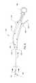
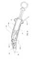
- FIG. 1is a perspective view of an embodiment of a surgical device of the present disclosure
- FIG. 2is an alternate perspective view of the surgical device depicted in FIG. 1 ;
- FIG. 3is a top view of the surgical device depicted in FIG. 1 ;
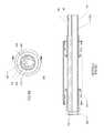
- FIG. 4is a side view of the surgical device depicted in FIG. 2 ;
- FIG. 4Ais an enlarged cross-sectional view of the distal end of the elongated flexible tubular member distal of the expandable member of the surgical device depicted in FIG. 4 ;
- FIG. 4Bis a cross-sectional end view of the elongated flexible tubular member of the surgical device depicted in FIG. 4 taken along line B-B;
- FIG. 4Cis a cross-sectional side view of the elongated flexible tubular member depicted in FIG. 4B taken along line C-C;
- FIG. 4Dis a cross-sectional view of the handle of the surgical device depicted in FIG. 4 ;
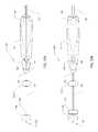
- FIG. 5Ais a cross-sectional view of the plunger located within the handle of the surgical device depicted in FIG. 4D , wherein the plunger is illustrated in an extended position;
- FIG. 5Bis a cross-sectional view of the plunger located within the handle of the surgical device depicted in FIG. 4D , wherein the plunger is illustrated in a retracted position;
- FIG. 5Cis a cross-sectional view of the syringe depicted in FIG. 5A ;
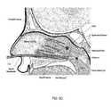
- FIG. 6Ais a cross-sectional view of a patient's head with an embodiment of a surgical device of the present disclosure, with the expandable member in a deflated state, entering the patient's nasal cavity;
- FIG. 6Bis a cross-sectional view of a patient's head with an embodiment of a surgical device of the present disclosure, with the expandable member in a deflated state, located in the patient's nasal cavity;
- FIG. 6Cis a cross-sectional view of a patient's head with an embodiment of a surgical device of the present disclosure, with the expandable member in a deflated state, located in the patient's nasal cavity with the expandable member disposed adjacent the choana;
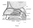
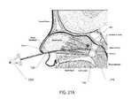
- FIG. 6Dis a cross-sectional view of a patient's head with an embodiment of a surgical device of the present disclosure, with the expandable member in an inflated state, located in the patient's nasal cavity with the expandable member disposed adjacent the choana;
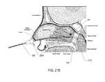
- FIG. 6Eis a cross-sectional view of a patient's head with an embodiment of a surgical device of the present disclosure, with the expandable member in an inflated state, located in the patient's nasal cavity with the expandable member disposed adjacent the choana and medication accumulated in the patient's nasal cavity adjacent the SPG;
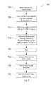
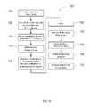
- FIG. 7is flow chart depicting a method of performing a surgical technique using a surgical device of the present disclosure
- FIG. 8Ais an enlarged cross-sectional view of an alternative embodiment of the distal end of the elongated flexible tubular member distal of the expandable member of the surgical device depicted in FIG. 4 ;
- FIG. 8Bis a cross-sectional end view of an alternative embodiment of the elongated flexible tubular member of the surgical device depicted in FIG. 4 taken along line B-B;
- FIG. 8Cis a cross-sectional side view of the elongated flexible tubular member depicted in FIG. 8B taken along line C-C;
- FIG. 9Ais a cross-sectional side view of an alternative embodiment of the elongated flexible tubular member depicted in FIG. 8C with the expandable member depicted in the expandable state;
- FIG. 9Bis a cross-sectional side view of another alternative embodiment of the elongated flexible tubular member depicted in FIG. 8C with the expandable member depicted in the expandable state;
- FIG. 10Ais a top view of an alternative embodiment of the surgical device depicted in FIGS. 1-4 ;
- FIG. 10Bis a top view of another alternative embodiment of the surgical device depicted in FIGS. 1-4 ;
- FIG. 11Ais a cross-sectional view of a patient's head with an embodiment of a surgical device of FIG. 10A located in the patient's nasal cavity with the expandable member disposed adjacent the choana and medication accumulated in the patient's nasal cavity adjacent the SPG and a second expandable member disposed adjacent and exterior of the patient's nostril;
- FIG. 11Bis a cross-sectional view of a patient's head with an embodiment of a surgical device of FIG. 10B located in the patient's nasal cavity with the expandable member disposed adjacent the choana and the delivery device in the patient's nasal cavity adjacent the SPG, and a second expandable member disposed adjacent and exterior of the patient's nostril;
- FIG. 12is flow chart depicting an alternative method of performing a surgical technique using an alternative embodiment of the surgical device of the present disclosure
- FIG. 13is a cross-sectional view of an alternative embodiment of the syringe illustrated in a retracted position during shipment;
- FIG. 13Ais an enlarged a cross-sectional view of the embodiment of the syringe of FIG. 13 , wherein the plunger is illustrated in a retracted position during shipment; in an extended position;
- FIG. 14is a cross-sectional view of an alternative embodiment of the syringe illustrated in an initially retracted position during shipment and/or prior to use;
- FIG. 14Ais an enlarged a cross-sectional view of an alternative embodiment of the syringe of FIG. 14 , wherein the plunger is illustrated in an initially retracted during shipment and/or prior to use;
- FIG. 15is a cross-sectional view of an alternative embodiment of the plunger illustrated in an extended position
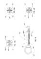
- FIG. 16is a side view of the plunger of the alternative embodiment of the syringe depicted in FIG. 13 ;
- FIG. 16Ais a cross-sectional view of the plunger in FIG. 16 , wherein the locking arms, particularly the distal ends of the locking arms, are in a fully radially outward extended position relative to the shaft portion of the plunger;
- FIG. 16Bis a cross-sectional view of the plunger in FIG. 16 , wherein the locking arms, particularly the distal ends of the locking arms, are in a fully radially inward position relative to the shaft portion of the plunger;
- FIG. 16Cis a cross-sectional view of the plunger in FIG. 16 , wherein the locking arms, particularly the distal ends of the locking arms, are in a partially radially outward extended position relative to the shaft portion of the plunger;
- FIG. 17is a side view of an alternative embodiment of the surgical device depicted in FIG. 4 ;
- FIG. 18is a cross-sectional view of the alternative embodiment of the handle of the surgical device depicted in FIG. 17 ;
- FIG. 19Ais an illustration of a schematic of a circuit wherein a pull tab is interrupting both paths of the circuit
- FIG. 19Bis an illustration of a schematic of a circuit wherein the pull tab in FIG. 19A is omitted and therefore not interrupting the circuit, which includes one closes path and one open path;
- FIG. 19Cis an illustration of a schematic of a circuit wherein the pull tab in FIG. 19A is omitted and therefore not interrupting the circuit, which includes two closed paths;
- FIG. 20Ais a perspective view of an alternative embodiment of a surgical device of the present disclosure, wherein the stabilizer is disposed proximate the handle of the surgical device;
- FIG. 20Bis a perspective view of the alternative embodiment of the surgical device illustrated in FIG. 20A , wherein the stabilizer is disposed distally of the handle of the surgical device;
- FIG. 21Ais a cross-sectional view of a patient's head and the embodiment of the surgical device illustrated in FIG. 20A , wherein the expandable member is in an inflated state and located in the patient's nasal cavity and disposed adjacent the choana, wherein the stabilizer is disposed distally of the patient's nose;
- FIG. 21Bis a cross-sectional view of a patient's head and the embodiment of the surgical device illustrated in FIG. 20A , wherein the expandable member is in an inflated state and located in the patient's nasal cavity and disposed adjacent the choana, wherein the stabilizer is disposed adjacent and/or contacts the patient's nose;
- FIG. 22Ais an enlarged perspective view of the stabilizer and elongated flexible tubular member illustrated in FIGS. 20A and 20B ;
- FIG. 22Bis a cross-sectional end view of the stabilizer and elongated flexible tubular member depicted in FIG. 22A taken along line A-A, wherein the stabilizer is in an uncompressed state;
- FIG. 22Cis an alternative embodiment of the cross-sectional end view of the stabilizer and elongated flexible tubular member depicted in FIG. 22A taken along line A-A, wherein the stabilizer is in a compressed state;
- FIG. 22Dis a cross-sectional end view of the stabilizer and elongated flexible tubular member depicted in FIG. 22A taken along line B-B;
- FIG. 23is flow chart depicting an alternative method of performing a surgical technique using an alternative embodiment of the surgical device of the present disclosure, particularly the alternative embodiment of the surgical device depicted in FIGS. 20A and 20B .
- FIG. 1 - FIG. 4depict a surgical device 100 having a handle 104 and an elongated flexible tubular member 108 .
- the handle 104which is ergonomically shaped, includes a proximal end and a distal end 144 .
- the proximal end of the handleincludes two projecting abutments 136 , 140 so that the user's hand remains comfortably on the handle 104 during use and the user's hand does not slide off the handle 104 .
- the projecting abutments 136 , 140may be disposed on the top and bottom of the handle such that they are about 180 degrees opposed from one another, as illustrated in the FIGS. 1 & 2 , or it may be preferable for the projecting abutments 136 , 140 to be disposed in a different orientation with respect to the handle, such as on the sides of the handle 104 . It may also be preferable to have less or more than two abutments. For example, it may be preferable to have a continuous abutment around the entire circumference of the handle 104 at or near its proximal end.
- the projecting abutments 136 , 140allow the clinician to ergonomically and comfortably depress and retract the barrel 172 .
- the clinicianmay insert his thumb in the ring 158 and locate his fingers on the distal side of the projecting abutments 136 , 140 and depress the barrel 172 with one hand.
- the handle 104is curved.
- the proximal portion of the handle 104has one longitudinal axis and the distal portion of the handle 104 has a different longitudinal axis.
- the longitudinal axis of the distal portion of the handle 104may be offset at an angle of about 5 degrees about 60 degrees from the longitudinal axis of the proximal portion of the handle 104 . It may be preferable for the offset angle to be about 10 degrees about 45 degrees and even more preferable for the offset angle to be about 20 degrees to about 30 degrees.
- the longitudinal axes of the proximal and distal portions of the handle 104smoothly intersect, thereby creating a handle with a curved profile.
- the distal end 144 of the of the handle portion 104may also have a rounded configuration, which is more ergonomic to engage the patient's nostril(s) upon insertion of the device 100 , namely the elongated flexible tubular member 108 , thereto.
- the elongated flexible tubular member 108includes a proximal end 120 , which is attached to the distal end of the 144 of the handle 104 .
- An expandable member 116such as a balloon, is located at, adjacent to or toward the distal end 124 of the flexible tubular member 108 .
- FIGS. 1 & 3depict the expandable member 116 in an inflated state
- FIGS. 2 & 4depict the expandable member 116 in a deflated state.
- the shape and size of the expandable member 116may differ depending upon the patient's anatomy. For example, the size of the expandable member 116 may be smaller for children and larger for adults. It may be preferable for the expandable member 116 to have an inflated diameter of about 1 cm to 4 cm, with a possible preferential diameter of about 2.5 cm, and an inflated length of about 1 cm to 3, with a possible preferential inflated length of about 2.5 cm.
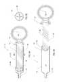
- the handle 104includes an inflation device, such as a syringe 112 , integrated therein.
- the syringe 112comprises a barrel 172 , a plunger 164 at least partially disposed within the barrel 172 , and a distal tip 176 at the end of the barrel 172 .
- the expandable member 116is expanded (inflated) with fluid, such as air, and when the plunger 164 is retracted, the expandable member 116 is collapsed (deflated).
- a pneumatic inflation devicewhich utilizes air as the fluid
- a hydraulic inflation devicewhich utilizes liquid (e.g., saline, water, etc.) as the fluid, can be used.
- the handle 104also includes a switch 128 for activating an illumination device 216 , such as a light-emitting diode (LED) disposed at or toward the distal end 124 of the elongated flexible tubular member 108 .
- the switch 216activates a power source, such as a battery, that is coupled to the illumination device 216 by two or more conductors (e.g., wires) 224 , 228 .
- the wires 224 , 228are disposed within lumens 224 , 228 that travel from the proximal end to the distal end of the elongated flexible tubular member 108 .
- the expandable member 116is also disposed at or near or toward the distal end 124 of the elongated flexible tubular member 108 . It is preferable for the illumination device 216 to be disposed distally of the expandable member 116 along the elongated flexible tubular member 108 , thereby allowing the illumination device 216 to project light in a manner that is unobstructed by the expandable member 116 . That is, it is preferable for the expandable member 116 to be disposed proximally of the illumination device 216 along the elongated flexible tubular member 108 . For example, it may be preferable for the distal end of the expandable member 116 to be disposed about 0 to 1 mm and potentially even more preferable to be disposed at the distal end 124 of the elongated flexible tubular member 108 .
- An alternative illumination device 216may include an illumination fiber (not shown) that is attached to and/or integral with the elongated flexible tubular member 108 such that the illumination fiber is exposed at the same location that the LED would have been disposed—at or toward the distal end 124 of the elongated flexible tubular member 108 .
- the proximal end of the illuminationis coupled to a light source that can be disposed interiorly and/or exteriorly of the handle 104 .
- the light sourcecan be powered by a direct current power source or an alternating current power source.
- FIG. 4Ais an enlarged cross-sectional view of the distal end 124 of the elongated flexible tubular member 108 illustrating a portion of the expandable member 116 in a deflated state.
- the distal end 124 of the elongated flexible tubular member 108includes a cover 220 coupled to it.
- the cover 220is constructed of a transparent material, such as polycarbonate.
- the cover 220protects the illumination device 216 .
- the cover 220may also be shaped such that its edges are curved, thereby providing an atraumatic end to the surgical device.
- the cover 220can be coupled directly to the distal face 222 of the elongated flexible tubular member 108 and/or it can be coupled to the perimeter of the distal end 124 of the elongated flexible tubular member 108 .
- the tip 220may preferably be coupled to the distal end 124 of the elongated flexible tubular member 108 by an adhesive compound.
- Alternative means of coupling the tip 220 to the distal end 124 of the elongated flexible tubular member 108includes mechanical means, such as pressed fittings, snap on fittings, or a threaded arrangement between the tip 220 and the elongated flexible tubular member 108 .
- an illumination device 216which is also coupled to the distal face 222 of the elongated flexible tubular member 108 such that the illumination device projects light distally of the elongated flexible tubular member 108 .
- the illumination device 216is coupled to the distal end 124 of the elongated flexible tubular member 108 by an adhesive. It may also be preferable for the tip 220 to surround at least a portion of the illumination device 216 , thereby protecting the illumination device 216 .
- the illumination deviceis powered by a power source, such as a battery, via one or more wires 224 , 228 that couple the power source to the illumination device 216 .
- the wires 224 , 228are disposed within lumens 224 , 228 that travel from the proximal end to the distal end of the elongated flexible tubular member 108 .
- FIG. 4Bthere is depicted a cross-sectional view of the elongated flexible tubular member 108 of the surgical device 100 depicted in FIG. 4 taken along line B-B.
- the elongated flexible tubular member 108comprises a plurality of lumens. Although a different number of lumens may be used, FIG.
- lumen 148is used to transport the medication to/from the medication port 160 located proximally of the expandable member 116 ;
- lumen 200is used to transport fluid (e.g., air, water, saline, etc.) to/from the inflation port, which open into the expandable member 116 ;
- two lumens 204 , 208provide channels for the wires 224 , 228 to travel.
- All four lumens 148 , 200 , 204 & 208have openings at the proximal end of the elongated flexible tubular member 108 . Not all four lumens, however, may have openings at the distal end of the elongated flexible tubular member 108 .
- the lumen 148 used to transport the medicationmay have an opening at the proximal end of the elongated flexible tubular member 108 and an opening (or port) at 160 through the wall of the tubular member 108 , which is located proximally of the expandable member 116 .
- the lumen 200 used to transport fluid to inflate the expandable member 116may have a have an opening at the proximal end of the elongated flexible tubular member 108 and an opening (or port) at 212 , which opens into the expandable member 116 .
- Lumens 204 , 208may have an opening at the proximal end of the elongated flexible tubular member 108 and an opening at or near the distal end of the elongated flexible tubular member 108 , thereby allowing the wires 224 , 228 to travel all or the majority of the length of the elongated flexible tubular member 108 to the illumination device 216 .
- the elongated flexible tubular member 108may not have lumens 204 , 208 .
- the elongated flexible tubular member 108is constructed (e.g., molded) in a manner such that the wires 224 , 228 are integral with the elongated flexible tubular member 108 , then lumens 204 , 208 may not be needed.
- the elongated flexible tubular member 108may have additional lumens 206 , 210 .
- Another alternative embodimentmay include an additional lumen in the elongated flexible tubular member 108 through which an imaging device may be inserted or incorporated.
- the surgical device 100may include a reusable endoscope that is inserted through an opening (not shown) in the handle 104 and travels through the additional lumen in the elongated flexible tubular member 108 such that the endoscope is adjacent the illumination device 216 in the cover 220 .
- FIG. 8A, 8B & 8Cthere is depicted such an alternative embodiment of the flexible tubular member 108 ′ that includes lumen 202 ′, which extends from the proximal end to the distal end of the flexible tubular member 108 ′, and is configured to have an endoscope or other imaging device inserted thereto.
- Lumen 148 ′will be used to transport the medication to/from the medication port 160 ′ located proximally of the expandable member 116 ; two lumens 204 , 208 provide channels for the wires 224 , 228 to travel to/from the illumination device 220 ; lumen 206 ′ is used to transport fluid (e.g., air, water, saline, etc.) to/from the inflation port, which open into the expandable member 116 ; and lumen 208 ′ is an additional lumen. Although it is not shown in the figures, it may also be desirable for the cover and/or the distal end of the flexible tubular member to have an optical divider that separates the light emitted by the illumination device from directly entering the endoscope or imaging device.
- an optical dividerthat separates the light emitted by the illumination device from directly entering the endoscope or imaging device.
- the opening 160may be disposed about 1 mm to 10 mm from the proximal end of the expandable member 116 and possibly more preferably to be disposed about 2 mm to 5 mm from the proximal end of the expandable member 116 . Locating the opening 160 through the wall of the tubular member 108 proximally of the proximal end of the expandable member 116 allows the medication to collect within the nasal cavity above the expandable member 116 , while the expandable member 116 is inflated.
- the medicationmay collect within the nasal cavity and form a pool of medication such that the level of medication rises to sphenopalatine fossa and/or the mucosa overlaying the SPG.
- the volume of medication introduced to the nasal cavity and used to create such a poolmay be between 2 milliliters to 15 milliliters, and potentially preferable for about 5 milliliters to 10 milliliters.
- an inflation devicesuch as a syringe 112
- the syringe 112is used to inflate and deflate the expandable member 116 . Integrating the inflation device in the handle 104 reduces the likelihood of a clinician confusing which port(s) to connect the devices (i.e., syringes) used to introduce the medication and the inflation fluid.
- an inflation devicesuch as the syringe 112
- a clinicianwill know and/or be instructed to use the integrated syringe 112 to inflate the expandable member 116 and an external syringe (not shown) to introduce the medication.
- a clinicianwill only have to introduce one fluid, namely the medication, through an external syringe, thereby reducing potential confusion as to which fluid to introduce and/or into which port.
- the syringe used to introduce the medicationmay be integrated into the handle 104 in lieu of the syringe 112 used to inflate and deflate the expandable member 116 .
- a further alternative embodimentmay include a handle 104 with two clearly marked integrated syringes—one syringe for the medication and another syringe for the inflation fluid.
- the syringe 112comprises a barrel 172 , a plunger 164 at least partially disposed within the barrel 172 , and a distal tip 176 having an opening at the distal end of the barrel 172 .
- the plunger 164has a shaft portion 166 and a proximal end 162 and distal end 168 at the respective ends of the shaft portion 166 .
- a cross section of the shaft portion 166is illustrated in FIG. 5C , which depicts the shaft portion 166 as having an “X” or “T” cross sectional profile. This cross sectional profile potentially increases the strength and rigidity of the shaft portion 166 .
- the proximal end 162 and a distal end 168may be coupled to the shaft portion 166 or be integrally formed thereto.
- the proximal portion 162may also have a handgrip or finger grip, such as a ring 158 , for a clinician to ergonomically and comfortably depress and retract the barrel 172 .
- a handgrip or finger gripsuch as a ring 158
- the barrel 172may also be preferable for the barrel 172 to have an opening (port) 170 through the wall of the tubular member 108 adjacent, at or toward its proximal end.
- the surgical device 100When the surgical device 100 is manufactured, it is assembled and/or packaged at a certain atmospheric pressure depending upon the geographic location of the manufacturing and/or packaging facility. The atmospheric pressure of the surgical site where the surgical device 100 is used, however, may be different than that at the manufacturing and/or packaging facility. Including the opening 170 through the wall of the barrel 172 allows the pressure within barrel to equalize with the pressure of the surgical site prior to use.
- the surgical device 100may also be preferable to ship the surgical device 100 in a configuration such that the plunger 164 is in a partially or fully retracted position such, thereby allowing the opening 170 to be located distally of the distal end 168 of the plunger 164 . Shipping the surgical device in this configuration may enhance the time for the pressure within the chamber of the barrel to equalize with the atmospheric pressure at the surgical site more quickly.
- cliniciansmay also repeatedly depress and retract the plunger 164 . Such repeated action has the potential to overinflate the expandable member 116 .
- Inclusion of the opening 170 through the wall of the barrel 172allows the pressure within barrel's chamber 174 to equalize with the atmospheric pressure upon retraction of the plunger 164 , thereby reducing the likelihood of overinflating the expandable member 116 . That is, upon depression of the plunger 164 , the pressure within the chamber 174 , as well as the pressure within the expandable member 116 , increases above atmospheric pressure at the surgical site.
- the pressure within the chamber 174decreases back to atmospheric pressure prior to another depression of the plunger 164 because the fluid within the chamber 174 is vented to the atmosphere via the opening 170 .
- Venting the fluid within the chamber 174also allows the expandable member 116 to deflate (or further deflate) upon application of pressure to the exterior of the expandable member 116 .
- the pressure within the expandable member 116may not immediately cause the expandable member 116 to completely deflate. That is, the expandable member 116 may retain a certain amount of fluid after retraction of the plunger, thereby allowing the expandable member 116 to remain partially inflated. Accordingly, when the surgical device 100 , including the expandable member 116 , is initially removed from the patient's nasal cavity, the expandable member 116 may be partially inflated.
- opening 170 within chamber 174allows the expandable member 116 to further deflate upon removal of the surgical device 100 , including the expandable member 116 , from the patient's nasal cavity. Allowing the expandable member 116 to further deflate upon removal of the surgical device 100 assists in reducing the likelihood of the expandable member 116 causing discomfort to the patient.
- a pressure relief valve 188is disposed between the syringe 112 and the expandable member 116 . Inclusion of the pressure relief valve 188 into the inflation circuit reduces the possibility of over pressurizing and over expanding the expandable member 116 , particularly during a clinician's repeated depression and retraction of the plunger 164 .
- the pressure relief valve 188is a valve used to control or limit the pressure in a circuit, such as the inflation circuit. The pressure is relieved by allowing the pressurized fluid (e.g., air) to flow to an auxiliary passage, preferably in the valve, out of the circuit.
- the pressure relief valveis designed or set to open at a predetermined set pressure to protect the expandable member 116 from being subjected to pressures that exceed the desired clinical limits.
- the pressure relief valveis forced open and a portion of the fluid is diverted through the auxiliary route vented to the atmosphere. As the fluid is diverted, the pressure inside the circuit decreases. Once the pressure within the pressure relief valve reduces back to or below the predetermined set pressure, the valve will close.
- the predetermined set pressuremay be set between about 5 psi (0.345 bars) to 15 psi (1.034 bars) or possibly between about 8 psi (0.552 bars) to 12 psi (0.827 bars) or nominally about 10 psi (0.690 bars).
- the pressure relief valve 188is coupled to the distal tip 176 of the syringe 112 .
- the distal end of the pressure relief valve 188is, in turn, coupled to the tube 192 that is coupled to the inflation lumen 148 in the elongated flexible tubular member 108 .
- the tube 192may be omitted by directly coupling the distal end of the pressure relief valve 188 to the inflation lumen 148 in the elongated flexible tubular member 108 .
- FIGS. 13-15may negate the need for the inclusion of the pressure relief valve 18 discussed herein above.
- FIGS. 13 and 13Aas well as FIGS. 16, 16A, 16B and 16C , there is depicted an alternative embodiment of the syringe 1312 of the present disclosure.
- the syringe 1312comprises a barrel 1372 , and a plunger 1364 at least partially inserted within the barrel 1372 .
- the plunger 1364has a shaft portion 1366 and a proximal end 1362 and distal end 1368 at the respective ends of the shaft portion 1366 .
- the barrel 1372includes a distal tip 1376 having an opening at the distal end of the barrel 1372 .
- the proximal end 1362 and a distal end 1368 of the plunger 1364may be coupled to the shaft portion 1366 or be integrally formed thereto.
- the proximal portion 1362may also have a handgrip or finger grip, such as a ring 1358 , for a clinician to ergonomically and comfortably depress and retract the barrel 1372 .
- the proximal end of the barrel 1372may include a flange 1374 that is disposed within a flange recess 1388 of a housing 1384 , which is coupled to the handle 104 .
- the handle 104may include an integral flange recess 1388 in which the flange 1374 may be disposed, thereby negating the need for a separate housing 1384 .
- the barrel 1372remains positionally fixed with respect to the handle 104 during shipment and use.
- barrel 1372 of the syringe 1312 in FIGS. 13 and 13Amay also be preferable for barrel 1372 of the syringe 1312 in FIGS. 13 and 13A to have an opening (port) 1370 through the wall of the barrel 1372 adjacent, at or toward its proximal end. Including an unobstructed opening 1370 within the proximal end, for example, of the barrel 1372 allows the pressure within the chamber of the barrel 1372 to equalize with the pressure of its current geographical location, such as the surgical site prior to use.
- the surgical device 100may also be preferable to ship the surgical device 100 in a configuration such that the plunger 1364 is in fully retracted position, thereby allowing the opening 1370 to be located distally of the distal end 1368 of the plunger 1364 and, therefore, unobstructed. Shipping the surgical device in this configuration allows the opening 1370 to be unobstructed by the plunger, thereby potentially decreasing the time for the pressure within the chamber of the barrel to equalize with the atmospheric pressure at the surgical site more quickly.
- the syringe 1312may include means for preventing the distal end 1368 , particularly the seal, of the plunger 1364 from moving distally of the opening 1370 in the barrel 1372 during shipment.
- One such meansmay include one or more locking arms 1380 coupled to the plunger 1364 , wherein the locking arms 1380 have an unconstrained radially biased position that is greater than the orifice of the housing 1384 .
- each of the locking arms 1380have a proximal end, which are coupled to the proximal end 1362 of plunger 1364 , and a distal end 1392 extending therefrom.
- the locking arms 1380are spring biased in a radially outward direction such that they flare radially outwards at their distal ends 1392 in comparison to their proximal ends.
- the distal ends 1392 of the locking arms 1380may also be preferable for the distal ends 1392 of the locking arms 1380 to include a male tapered portion which mates with a female tapered portion 1400 of the housing 1384 .
- the male tapered portion of the distal ends 1392 of the locking arms 1380remains proximate the female tapered portion 1400 of the housing 1384 .
- the radially outward spring bias of the locking arms 1380which causes the distal ends 1392 , and particularly the male tapered portion, of the locking arms 1380 to have a configuration outside the chamber of the barrel 1372 such that the distal ends 1392 and/or the male tapered portion is biased outwardly to a diameter that is greater in diameter than the orifice of the housing, thereby causing the distal end 1392 and/or male tapered portion of the plunger 1364 to abut and contact the female tapered portion 1400 of the housing 1384 .
- the seal 1368is proximal of the opening 1370 within the barrel 1372 . That is, the plunger 1364 , particularly the shaft portion 1366 of the plunger 1364 , has a predetermined length between the distal ends 1392 and/or the male tapered portions of the distal end 1392 of the locking arms 1380 and the seal 1368 such that when the surgical device is in its fully retracted position during shipment and prior to use, the seal 1368 has a length that is proximal of the opening 170 , thereby allowing the chamber within the barrel 1372 to have the same pressure as the atmosphere for the geographic location of the surgical device.
- the plunger, 1364may also be preferable for the plunger, 1364 to include one or more cross sectional members 1404 having a circumference greater than a portion of lumen within the barrel. Such portion may have a reduced diameter at a ledge or ramp 1408 within the interior of the barrel's chamber. Such cross sectional members 1404 and ramp 1408 reduce the likelihood of the plunger 1364 from moving proximally out of the barrel 1372 during shipment.
- the plunger 1364upon opening the package in which the surgical device 100 is shipped, the plunger 1364 is in its fully retracted position (or un-activated position). That is, during shipment and prior to use of the surgical device 100 , the plunger 1364 is in its fully retracted position (or un-activated position).
- the clinicianmay manually force the plunger 1364 axially in a distal direction such that the male tapered portion of the distal ends 1392 of the locking arms 1380 move radially inward upon contacting the female tapered portion 1400 of the housing 1384 and into the orifice of the housing 1384 .
- the resiliency of the locking arms 1380forces the distal end 1392 of the locking arms 1380 to move radially outward. And because the lumen or chamber at the proximal end of the barrel 1372 is larger than the orifice of the housing 1384 , the distal ends 1392 of the locking arms 1380 are allowed to move radially outward after moving axially past the orifice of the housing 1384 and into the chamber of the barrel 1372 .
- the distal ends 1392 of the locking arms 1380are flanged in comparison to at least a portion of the locking arms 1380 proximal thereto, thereby allowing the flanged portions of the distal ends 1392 of the locking arms 1380 to be adjacent and/or abut the interior of the ridge 1396 at the orifice of the housing 1384 .
- the length of the plunger 1364is also designed such that, upon the distal end 1392 (including the flanged portion and male tapered portions) of the locking arms 1380 springing radially outward upon introduction into the lumen of the barrel 1372 , the seal at the distal end 1368 of the plunger 1364 is disposed at or distally of the opening 170 in the barrel 1372 . That is, the plunger 1364 , particularly the shaft portion 1366 of the plunger 1364 , has a predetermined length between the distal ends 1392 of the locking arms 1380 and the seal 1368 such that once the surgical device is in its initial partially retracted position and ready for use, the seal 1368 aligns with or is distal of the opening 170 , thereby sealing the barrel's chamber. Sealing the opening 170 ensures that no additional fluid will enter the chamber and the initial pressure within the lumen of the barrel 1372 will be equal to that of the atmospheric pressure for the geographic location of the surgical device immediately after sealing.
- the cliniciancan push the plunger 1364 towards the distal end 1376 of the barrel 1372 .
- the seal 1368moves distally of the opening 1370 , thereby increasing the fluid pressure within the barrel's chamber, inflation lumen, and expandable member 116 , which is then inflated.
- the plunger 1364particularly the shaft portion 1366 of the plunger 1364 , has a predetermined length between the distal ends 1392 of the locking arms and the seal 1368 such that once the surgical device moves in a axially distal direction from its partially retracted position, the seal 1368 is distal of the opening 170 within the barrel 1372 , thereby continuing to seal the barrel's chamber.
- the clinicianpushes and extends the plunger distally, the clinician can then pull or retract the plunger 1364 such that it moves proximally.
- the cliniciancan only pull the plunger proximally to a position wherein the locking arms 1380 abut and/or are adjacent the interior of the ridge 1396 at the distal end of the orifice of the housing 1384 , as illustrated in FIGS. 14 and 14A .
- the locking arms 1380not only serve as a for preventing the distal end 1368 , particularly the seal, of the plunger 1364 from moving distally of the opening 1370 in the barrel 1372 during shipment, but the locking arms 1380 also serve as a means for maintaining a sealed chamber during use of the surgical device.
- cliniciansmay repeatedly depress and retract the plunger 1364 .
- Inclusion of the opening 1370 through the wall of the barrel 1372allows the pressure within barrel's chamber 1374 reduces the likelihood of overinflating the expandable member 116 because prior to its use, the chamber 1374 is at atmospheric pressure for the geographical position at which the surgical device will be used. That is, upon depression of the plunger 1364 , the pressure within the chamber 1374 , as well as the pressure within the expandable member 116 , increases above atmospheric pressure at the surgical site.
- the pressure within the chamber 1374decreases back to atmospheric pressure prior to another depression of the plunger 1364 because no additional the fluid will enter the chamber 174 upon retraction.
- the plunger 1364When the plunger 1364 is in a position within the barrel 1372 such that the male tapered portions of the distal ends 1392 of the locking arms 1380 are proximal and/or abuts the female tapered portion 1400 of the housing 1384 , as illustrated in FIGS. 13 and 13A , the plunger 1364 is in its initial fully retracted position, which may be the desirable position for shipment and prior to use.
- the locking arms 1380particularly the distal ends 1392 of the locking arms 1380 , are in a fully radially outward extended position relative to the shaft 1366 portion of the plunger, such that the distal ends 1392 do not contact the shaft 1366 , as depicted in FIG. 16A .
- the radial exterior of the distal ends 1392 of the locking arms 1380are situated outward relative to the exterior of the shaft portion 1366 .
- the exterior of the distal ends 1392 of the locking arms 1380 and the exterior of the shaft portion 1366have the same radial position relative to one another.
- FIG. 16Billustrates the distal ends 1392 of the locking arms 1380 contacting the shaft 1366 .
- the plunger 1364When the plunger 1364 is in a position within the barrel 1372 such that the flanged portions and/or the male tapered portions of the locking arms 1380 are distal the female tapered portion 1400 of the housing 1384 and into the housing 1364 such as the flange of the distal end 1392 of the locking arms 1380 abuts and/or is adjacent the interior of the ridge at the orifice of the housing 1384 , as illustrated in FIGS. 14 and 14A , or distal thereto, the plunger 1364 is in its partially retracted position and ready for use.
- the plunger 1364When the plunger 1364 is in a position within the barrel 1372 such that the flanged portions and/or male tapered portions of the locking arms 1380 are distal the female tapered portion 1400 of the housing 1384 and into the housing 1364 such that the flange of the distal end 1392 of the locking arms 1380 is distal the interior of the ridge 1396 at the orifice of the housing 1384 , as illustrated in FIG. 15 , the plunger 1364 is in an extended position. Also, when the plunger 1364 is in a partially retracted position (as depicted in FIGS. 14 and 14A ) and/or in an extended position (as depicted in FIG.
- FIG. 16Cillustrates the distal ends 1392 of the locking arms 1380 being spaced apart from and not contacting the shaft 1366 but having less space between the distal ends 1392 and the shaft 1366 in comparison to FIG. 16A .
- this figurealso illustrates a female luer adaptor 132 attached to the surgical device 100 .
- the female luer adaptor 132allows a clinician to connect an auxiliary syringe (not shown) having a male luer the mates with the female luer adaptor 132 .
- the auxiliary syringewill include the medication that is introduced through the surgical device 100 proximal of the expandable member to the mucosa overlaying the SPG.
- actuatione.g., depression
- the auxiliary syringeUpon actuation (e.g., depression) of the auxiliary syringe, the medication travels from the auxiliary syringe to the female luer adaptor 132 through a tube 184 to the medication lumen 200 and eventually to opening 160 .
- the tube 184may be omitted by directly coupling the female luer adaptor 132 to the medication lumen 200 .
- An additional alternative to the present disclosureincludes using a separate tube for delivering the medication in lieu of the medication lumen 200 within the elongated flexible tubular member 108 .
- the separate tubecould be attached or unattached to the elongated flexible tubular member 108 .
- the separate tubewould have a proximal end, which could be coupled to the auxiliary syringe, and a distal end that includes an opening for delivering the medication.
- the medicationis preferably introduced through the surgical device 100 after the expandable member 116 is expanded because expanding the expandable member 116 reduces the likelihood of the medication from flowing down the patient's throat.
- the medicationcollects within the nasal cavity above the expandable member, when the expandable member 116 is expanded adjacent the choana. It may be preferable for the medication to collect within the nasal cavity and form a pool of medication such that the level of medication rises to sphenopalatine fossa and/or the mucosa overlaying the SPG.
- the medicationmay be desirable for the medication to remain in the patient's nasal cavity for a period of time to maximize the medication's exposure to the mucosa overlaying the SPG and the SPG itself.
- the auxiliary syringemay remain connected to the female luer adaptor 132 during such time period.
- the clinicianmay retract the auxiliary syringe, thereby removing some or all of the medication from the patient's nasal cavity through the same opening 160 used to introduce the medication. That is, by retracting the syringe, a negative pressure or suction force is created in the medication circuit, thereby pulling the medication located within the patient's nasal cavity through the opening 160 and back into the same or different auxiliary syringe.
- the expandable member 116is collapsed, and the surgical device 100 may be removed.
- the benefit of including the expandable member 116 with the surgical device 100allows the clinician to create a blockage within the patient's throat and fill a portion of the nasal cavity such that medication directly contacts the mucosa overlaying the SPG for a sustained period while preventing the medication from flowing down the patient's throat.
- Step 704which is illustrated in FIG. 6A , includes inserting the surgical device 100 into the patient's nasal cavity through one of the patient's nostrils (i.e., left nostril or right nostril).
- the distal portion of the distal end 124 of the elongated flexible tubular member 108is preferably inserted into the patient's nostril, while the expandable member 116 is entirely or partially deflated, and directed into the channel below the inferior turbinate and above the hard palate. It may also be preferable at the time of insertion of the surgical device 100 or shortly thereafter, that the illumination device 216 be activated. Upon activating the illumination device 216 , light will transmit through the patient's hard palate. For example, when the distal end 124 of the elongated flexible tubular member 108 (and the illumination device 216 ) is located within the patient's nasal cavity as depicted in FIG.
- the illumination device 216will be located at or below the posterior inferior turbinate and above the hard palate and be visible to a clinician viewing the interior of the oral cavity (patient's mouth), particularly the bottom of the palate (roof of the patient's mouth), and the light will appear to be transilluminating therefrom within the patient's head and visible to clinician from the oral cavity.
- the distal portion of the distal end 124 of the elongated flexible tubular member 108is inserted further into the patient's nasal cavity.
- the illumination device 216will continue to be located below the anterior of the inferior turbinate above the anterior of the hard palate further towards the soft palate in comparison location depicted in FIG. 6A .
- the distal portion of the distal end 124 of the elongated flexible tubular member 108is even inserted further into the patient's nasal cavity.
- the illumination device 216will be located above the soft palate, namely the nasopharynx, and the light will appear to be transilluminating therefrom and visible to clinician from the oral cavity.
- step 704 of FIG. 7has been completed because the expandable member 116 is located at the desired position, namely in the nasopharynx adjacent the choana.
- depth markersprinted on the elongated flexible tubular member 108 , wherein the depth markers indicate to the clinician the distance from the expandable member 116 to the corresponding depth marker.
- the elongated flexible tubular member 108may include depth markers every 1 centimeter, every 5 centimeters, every 10 centimeters from the proximal, mid- or distal portion of the balloon (or from the distal end of the flexible tubular member 108 ) to the corresponding depth marker.
- Adding such depth markersmay provide the clinician with an additional or alternative means of determining whether the expandable member 116 and/or the distal end of the flexible tubular member 108 is located at the desired position, namely in the nasopharynx adjacent the choana.
- the expandable member 116is expanded by depressing plunger 164 of the syringe 112 , as depicted in step 712 of FIG. 7 , thereby blocking the choana.
- medicationis introduced to the nasal cavity through the opening 160 of the flexible tubular member 108 .
- the expanded expandable member 116prevents the flow of medication down the patient's throat. And because the patient's head it typically tilted backwards during this procedure, the medication collects proximally above the expandable member 116 .
- the medicationbegins to accumulate within the nasal cavity.
- the level of medicationrises within the nasal cavity, namely the sphenopalatine fossa, such that the medication contacts the mucosa overlaying the SPG.
- Introducing the medication in this fashion and maintaining the desired level of medicationprovides for direct and sustained contact with the mucosa overlaying the SPG.
- the medicationis absorbed by the permeable mucosa overlying the SPG.
- the device(s) and method(s) of the present disclosureprovide direct and sustained contact with the mucosa and SPG, which is a more effective treatment.
- varying the medication and contact timesmay further increase the effectiveness of the treatment. Varying the medication and contact times also provide the clinician the flexibility to personalize the patient's treatment. Another example of the way in which the clinician may utilize the device(s) and method(s) of the present disclosure to personalize the patient's treatment includes inflating the inflatable member to a certain pressure.
- the patient's headmay be tilted backwards during the procedure.
- such meansmay include a deflector 902 that directs the flow of medication exiting the flexible tubular member 108 ′ toward the expandable member 116 . Directing the flow of medication toward the expandable member 116 reduces the likelihood that the medication will be distributed, via spraying, in an unknown direction. As illustrated in FIG. 9A , the deflector 902 is coupled to the flexible tubular member 108 .
- the deflector 902can be located exteriorly of the flexible tubular member 108 , such as in the form of a sleeve that surrounds the opening 160 , thereby forcing the outflow of medication towards the inflatable member 116 .
- the deflector 902can also be integral with the flexible tubular member 108 ′, such that the portion of the flexible tubular member 108 ′ adjacent the opening 160 directs the outflow of medication towards the inflatable member 116 .
- the deflector 902may also be a separate component that is inserted at least partially within the flexible tubular member 108 ′ and directs the outflow of medication towards the inflatable member 116 .
- the means for controlling the direction from which the medication exits the flexible tubular member 108 ′ and is introduced to the nasal cavitymay include the opening 160 having a particular directional shape such that the shape of the opening 160 directs the outflow of medication in a direction towards the inflatable member 116 .
- a further alternative means for controlling the direction from which the medication exits the flexible tubular member 108 ′ and is introduced to the nasal cavityincludes the opening 160 adjacent the expandable member 116 , wherein a deflector is omitted.
- the expandable member 116may optionally have an inflated configuration such that its shape includes a narrower width (or cross sectional profile) proximal the flexible tubular member 108 ′ and a wider width (or cross sectional profile) distal the flexible tubular member 108 ′. This may allow the opening 160 , which is adjacent the narrower width portion of the flexible tubular member 108 ′ to have a perpendicular orientation within and the flexible tubular member 108 ′ such that upon medication exiting the opening 160 , the medication contacts the wider width portion of the flexible tubular member 108 ′. And after the level of the pool of medication rises above the opening 160 distal the expandable member 116 , the additional medication exiting the opening enters directing in the pool.
- the medicationmay be preferable for the medication to remain within the nasal cavity and contact the mucosa overlaying the SPG, as well as the SPG, for a predetermined period of time (e.g., about 20 minutes), as discussed above.
- a predetermined period of timee.g., about 20 minutes
- the medicationis removed from the nasal cavity by suctioning the medication through the opening 160 with an auxiliary syringe.
- the expandable member 116may be collapsed by retracting the plunger 164 of the syringe 112 , as depicted in step 728 of FIG. 7 .
- the surgical device 100may be removed from the nasal cavity.
- the procedure discussed above with respect to FIG. 7performs a sphenopalatine ganglion block for one SPG located on one (i.e., left or right) side of the patient's head.
- the same procedurecan be repeated by inserting the distal end of the elongated flexible tubular member 108 into the patient's other nostril and applying the medication to the other SPG.
- FIG. 10Athere is depicted an alternative embodiment of the surgical device 100 depicted in FIGS. 1-4 .
- the surgical device 100 depicted in FIGS. 1-4includes expandable member 116 located at, adjacent to or toward the distal end 124 of the flexible tubular member 108 .
- the surgical device 100 ′may include a second expandable member 118 disposed proximally of expandable member 116 and the opening 160 .
- the expandable member 116 of the surgical device 100allows the clinician to create a blockage within the patient's throat and fill a portion of the nasal cavity such that medication directly contacts the mucosa overlaying the SPG for a sustained period while preventing the medication from flowing down the patient's throat.
- the second expandable member 118may be used to prevent the medication from exiting the patient's nostril.
- the expandable member 116is disposed adjacent the choana, the expandable member 116 is inflated, and medication is introduced to patient's nasal cavity through the opening 160 , and the medication collects above the expandable member 116 and adjacent the SPG.
- the second expandable member 118is disposed adjacent the exterior of the patient's nostril or in the patient's nostril, and the second expandable member 118 is inflated. Inflating the expandable member 116 adjacent the choana and the second expandable member 118 adjacent patient's nostril allows the medication to collect between the two expandable members 116 , 118 while preventing the medication from flowing down the patient's throat and escaping through the patient's nostril, particularly if the patient moves his/her head and/or when the patient's head is not in the most desirable orientation.
- the second expandable member 118may be coupled to the same inflation lumen and inflation port used to inflate expandable member 116 so that the two expandable members 116 , 118 are inflated simultaneously.
- the surgical device 100 ′may include a second inflation lumen (not shown) and/or a second inflation port (not shown) to inflate the second expandable member 118 separately from expandable member 116 .
- the distance from the entry of a patient's nostril to a patient's choanamay vary among patients. Accordingly, it may be desirable to have a means for adjusting the distance between the two expandable members 116 , 118 . For example, it may be desirable to have a means for sliding the second expandable member 118 over the elongated flexible tubular member 108 .
- the surgical device 100depicted in FIGS. 1-4 .
- the surgical device 100 ′′ illustrated in FIG. 10Bfurther includes a delivery device 117 between the expandable members 116 , 118 for delivering the medication.
- the delivery device 117may include an expandable member having a permeable membrane or semi-permeable membrane disposed over the opening 160 such that upon expansion, pores within the permeable membrane or semi-permeable membrane increase in size and allow the medication to exit there through.
- the delivery device 117may alternatively include a sponge disposed over opening 160 . As depicted in FIG.
- the surgical device of FIG. 10Bit may be preferable to locate the surgical device of FIG. 10B in the patient's nasal cavity with the expandable member 116 disposed adjacent the choana, the delivery device 117 in the patient's nasal cavity adjacent the SPG, and the second expandable member 118 disposed adjacent and exterior of the patient's nostril. Once the delivery device 117 is located adjacent the SPG, the medication is delivered through the delivery device 117 .
- the surgical deviceis used only for treating a single patient and not used for treating multiple patients.
- the surgical devicemay be used on both sides of the patient's nasal cavity by inserting the surgical device into both nostrils of the patient, wherein the treatment of each side of the nasal cavity for the same patient may be considered a separate procedure.
- the LEDis battery powered.
- One method of insuring that the surgical device is only used on a single patientis to preclude the use of the LED, and therefore, prevent the surgical device's ability to transilluminate through tissue after a predetermined time. Precluding the use of the LED may be assured by depleting the batteries power supply.
- a typical sphenopalatine ganglion block proceduremay take between 5 minutes and 35 minutes for one side of the nasal cavity. That is, it may take between 10 minutes and 70 minutes for a clinician to complete a sphenopalatine ganglion block procedure for both sides of the patient's nasal cavity. Accordingly, if the battery power is depleted after such predetermined time, then the LED will be inoperable.
- FIG. 17there is depicted the proximal end of a pull tab 1602 inserted into the handle 1602 of the surgical device in an un-pulled position.
- FIG. 18the distal end of the pull tab 1602 is disposed adjacent the battery terminal or between the battery terminals to interrupt and maintain an open circuit as schematically depicted in FIG. 19A .
- FIGS. 19A, 19B, and 19Cthere is shown a schematic diagram of a circuit 1900 in three different phases.
- the circuit 1900has two potential circuit paths: one potential circuit path includes delivering power from the battery 1904 to the resister 1908 ; and the other potential circuit path includes delivering power from the battery 1904 to the resister LED, which is indicated as item 216 in these figures.
- both circuit pathsremain open.
- inclusion of the pull tab 1602 in an un-pulled positioninsures that both circuit paths will be remain open, thereby preventing the resistor 1908 and the LED 216 from drawing power from the battery. Also depicted within the circuit of FIG.
- the switch 128is in an open position because it is not depressed. Referring to FIG. 19B , the switch 128 is still in an open position.
- the circuit path to the LED 216is, therefore, open in both FIGS. 19A and 19B .
- the circuit path to the resistor 1908is open in FIG. 19A , but the circuit path to the resistor 1908 is closed in FIG. 19B because the pull tab 1602 has been removed and illustrated in a pulled-position. Once the pull tab 1602 is removed and/or in a pulled position, the resistor 1908 begins drawing power from the battery 1904 .
- the power capacity of the battery 1904 and/or the size of the resistor 1908are designed or configured to utilize all of the battery's power capacity within a predetermined time, thereby preventing a clinician from performing more than one sphenopalatine ganglion block procedure on a single patient.
- FIG. 19Conce the switch 128 is in a closed position, the circuit path to the LED 1816 is also closed. Accordingly, this figure illustrates both circuit paths in closed positions—the battery 1904 is delivering power to the resister 1808 and to the LED 1816 .
- An alternative means of depleting the battery power in a predetermined timeincludes a one way switch for the LED such that LED always remains on, thereby continuously draining battery power. If this means is used, the power supply and/or resistance of the LED would be designed to deplete the battery power within a predetermined time.
- FIGS. 20A and 20Bthere is depicted a further alternative embodiment of the surgical device 100 ′′′ depicted in FIGS. 1-4 .
- the surgical device 100 ′′′ illustrated in FIGS. 20A and 20Balso includes a stabilizer 2004 slidably disposed over the flexible tubular member 108 between the distal end 144 of the handle 104 and the expandable member 116 .
- the stabilizer 2004is able to slide over and relative to the flexible tubular member 108 . For instance, FIG.
- FIG. 20Aillustrates the stabilizer 2004 adjacent to and/or distal the distal end 144 of the handle 104 (or at and/or adjacent the proximal end of the flexible tubular member 108 ) and proximal the expandable member 116 (or proximal the distal end of the flexible tubular member 108 ).
- FIG. 20Billustrates the stabilizer 2004 distally of the distal end 144 of the handle 104 (or distally of the proximal end of the flexible tubular member 108 ) and more proximal the expandable member 116 (or more proximal the distal end of the flexible tubular member 108 ), in comparison the position of the stabilizer 2004 depicted in FIG. 20A .
- the location of the stabilizer 2004is initially distal the patient's nose.
- the clinicianmay slide the stabilizer 2004 along the elongated flexible tubular member 108 such that the stabilizer 2004 contacts the patient's nose or anterior naris or is located adjacent to either the patient's nose or anterior naris.
- the stabilizer 2004assists in securing the expandable member 116 in its desired location, namely adjacent the choana in its inflated state.
- the stabilizer 2004provides anterior traction on the seated expandable member 116 from exterior the patient's nasal cavity, nose and/or anterior naris. That is, the stabilizer 2004 aids in retaining the expandable member 116 (and/or the expandable member 118 ) in position while the clinician is performing the sphenopalatine ganglion block procedure.
- the stabilizer 2004may prevent the surgical device 100 ′′′ or a portion thereof, namely the flexible tubular member 108 (or a portion thereof) and/or the expandable member 116 from moving and/or becoming unseated during inflation in the event the patient moves.
- rapid or quick movement of the patient's headsuch as movement resulting from a cough or a sneeze, may cause the expandable member 116 to also move.
- the seal formed by the expandable member 116 against the choanamay become unseated or unstable, thereby allowing the fluid (e.g., medication) located above the expandable member 116 to leak past the expandable member 116 and into the patient's throat.
- the configuration of the stabilizer 2004 depicted in this figureis such that it remains completely outside the patient's nose and does not enter the patient's nostril or nasal vestibule.
- the configuration of the stabilizercould be designed to be placed partially or completely inside the patient's nostril.
- the stabilizercould be designed such that one portion of the stabilizer is inside the patient's nostril and another portion of the stabilizer is outside the patient's nose.
- the stabilizer 2004 depicted in these figuresis configured to remain completely outside the patient's nose without any portion thereof entering the patient's nostril or nasal vestibule.
- Stabilizer 2004has a proximal portion 2012 , a distal portion 2008 and a lumen 2016 extending along the longitudinal axis of the stabilizer 2004 and through both the proximal portion 2012 and the distal portion 2008 . That is, the lumen 2016 extends from the proximal end of the proximal portion 2012 to the distal end of the distal portion 2008 of the stabilizer 2004 .
- the proximal portion 2012 of the stabilizer 2004has a smaller cross-sectional profile in comparison to the distal portion 2008 , although the relative sizes of such cross-sectional profiles may be reversed or the same.
- the cross-sectional profile of the distal portion 2008may have a generally saddle shape.
- the distal portion 2008may have a top portion 2020 , a bottom portion 2024 , and two side portions 2028 , 2032 .
- the length between the top portion 2020 and bottom portion 2024may be less than the length between the two side portions 2028 , 2032 .
- top portion 2020 and bottom portion 2024may each have a convex shape, and the two side portions 2028 , 2032 may each have concave shapes, thereby creating a saddle-shaped cross sectional profile for the distal portion 2008 of the stabilizer 2004 .
- the concave shaped side portions 2028 , 2032also create indentations that allow the clinician to easily grasp the stabilizer 2004 with his/her finger(s) and/or thumb.
- the stabilizer 2004may be constructed of a flexible and/or polymeric material, such as silicone. Upon a clinician grasping the flexible stabilizer 2004 and squeezing it on the side portions 2028 , 2032 , as illustrated by the arrows depicted in FIG. 22C , the stabilizer 2004 is forced into and enters a compressed state. And when the clinician releases the stabilizer 2004 , it returns to an uncompressed state, as depicted in FIG. 22B .
- the stabilizer 2004comprises a lumen 2016 extending along the longitudinal axis of the stabilizer 2004 and through both the proximal portion 2012 and the distal portion 2008 such that the lumen 2016 extends from the proximal end of the proximal portion 2012 to the distal end of the distal portion 2008 of the stabilizer 2004 .
- the cross-sectional profile of the lumen 2016may vary or remain constant from its proximal end to its distal end.
- the shape of the lumen at and/or towards its proximal endmay be circular, while the shape of the lumen at and/or towards its distal end may be oval or vice versa.
- FIG. 22Bdepicts the cross-sectional shape of the lumen 2016 as oval at the distal portion 2008 of the stabilizer 2004
- FIG. 22Cdepicts the cross-sectional shape of the lumen 2016 as circular at the distal portion 2008
- FIG. 22Ddepicts the cross-sectional shape of the lumen 2016 as circular at the proximal portion 2012 .
- the circumference of such circle or ovalis greater than the circumference of the flexible tubular member 108 extending through the lumen 2016 .
- the size of the circumference of the lumen 2016being greater than the size of the circumference of the flexible tubular member 108 insures that the stabilizer 2004 can slide relative to the flexible tubular member 108 . Even though the circumference of the lumen 2016 is greater that of the flexible tubular member 108 , the lumen 2016 contacts the flexible tubular member 108 in either its compressed state or its uncompressed state.
- the cross-sectional shape of the lumen 2016is oval at its distal end and transitions to a circular shape at its proximal end, as illustrated in FIGS. 22B and 22D , one or more portions of the lumen 2016 contacts one or more portions the flexible tubular member 108 , when the stabilizer 2004 is in an uncompressed state. And upon a clinician grasping the flexible stabilizer 2004 and squeezing it on the side portions 2028 , 2032 , the stabilizer 2004 is forced into and enters an compressed state, as illustrated in an FIG. 22C , such that no portion of the lumen 2016 contacts any portion the flexible tubular member 108 when the stabilizer 2004 is in a compressed state.
- the stabilizer 2004When the stabilizer 2004 is in a compressed state, the stabilizer is able to slide over the flexible tubular member 108 , and when the stabilizer 2004 is in an uncompressed state, the stabilizer 2004 is unable to slide over the flexible tubular member 108 due to the frictionally contact between the stabilizer 2004 and the flexible tubular member 108 .
- the stabilizer 2004Upon release of the stabilizer 2004 by the clinician, the stabilizer 2004 returns to an uncompressed state, and the shape of the lumen 2016 returns to that of the oval depicted in FIG. 22B , thereby creating contact between the stabilizer 2004 and the flexible tubular member 108 and preventing sliding of the stabilizer 2004 over the flexible tubular member 108 due to the friction between the two components.
- the surface of the distal end of the distal portion 2008 of the stabilizer 2004is flat or relatively flat.
- the flat shape of the distal end of the distal portion 2008insures that the stabilizer 2004 remains completely outside the patient's nose upon sliding it adjacent thereto.
- the stabilizer 2004may comprise a gusset 2006 that buttresses the distal portion 2008 of the stabilizer 2004 , particularly the proximal face 2036 of the distal portion 2008
- FIG. 23there is depicted a flow chart 700 ′′ representing at least some of the steps of an alternative method of performing the surgical technique of performing using the alternative embodiment of the surgical device 100 ′′′ of the present disclosure.
- the flow chart 700 ′′ depicted in FIG. 23is similar to the flow chart depicted in FIG. 7 , with the exception that the flow chart 700 ′′ depicted in FIG. 23 also includes one or both of the following steps: step 715 , which includes sliding the stabilizer 2004 adjacent and/or against the patient's nose (after step 712 and prior to step 716 ); and step 726 , which includes sliding the stabilizer 2004 away from the nose (after step 724 and prior to step 728 ).
- steps 715 and 726are depicted in certain locations within the flowchart, these steps do not necessarily need to be performed in this particular order during the surgical procedure. For example, steps 715 and 726 may be performed prior and/or after other steps depicted within the process. Regardless of where steps 715 and 726 are performed during the sphenopalatine ganglion block procedure, utilizing the stabilizer 2004 aids in holding the expandable member 116 (and/or the expandable member 118 ) in position while the clinician is performing this surgical procedure.
- the clinicianmay first use an endoscope or other medical device to perform a nasal examination and inspect the patient's nasal cavity and insure that nasal mucosa is intact and there are not any obvious internal anatomic obstruction within the patient's nasal cavity that would prevent the passage of the device described herein, which may have a diameter of about 4 mm.
- This method of disclosureis not to be interpreted as reflecting an intention that the claims require more features than are expressly recited in each claim. Rather, as the following claims reflect, inventive aspects lie in less than all features of a single foregoing disclosed aspect, embodiment, and/or configuration. Thus, the following claims are hereby incorporated into this Detailed Description, with each claim standing on its own as a separate preferred embodiment of the disclosure.
Landscapes
- Health & Medical Sciences (AREA)
- Life Sciences & Earth Sciences (AREA)
- Surgery (AREA)
- Heart & Thoracic Surgery (AREA)
- Engineering & Computer Science (AREA)
- Public Health (AREA)
- General Health & Medical Sciences (AREA)
- Veterinary Medicine (AREA)
- Biomedical Technology (AREA)
- Animal Behavior & Ethology (AREA)
- Biophysics (AREA)
- Molecular Biology (AREA)
- Medical Informatics (AREA)
- Nuclear Medicine, Radiotherapy & Molecular Imaging (AREA)
- Optics & Photonics (AREA)
- Physics & Mathematics (AREA)
- Radiology & Medical Imaging (AREA)
- Pathology (AREA)
- Pulmonology (AREA)
- Hematology (AREA)
- Anesthesiology (AREA)
- Child & Adolescent Psychology (AREA)
- Dentistry (AREA)
- Oral & Maxillofacial Surgery (AREA)
- Otolaryngology (AREA)
- Microelectronics & Electronic Packaging (AREA)
- Surgical Instruments (AREA)
Abstract
Description
Claims (20)
Priority Applications (3)
| Application Number | Priority Date | Filing Date | Title |
|---|---|---|---|
| US15/008,115US9839347B2 (en) | 2013-12-17 | 2016-01-27 | Method of performing a sphenopalatine ganglion block procedure |
| US15/166,102US10016580B2 (en) | 2013-12-17 | 2016-05-26 | Methods for treating sinus diseases |
| US15/798,072US10420459B2 (en) | 2013-12-17 | 2017-10-30 | Method of performing a sphenopalatine ganglion block procedure |
Applications Claiming Priority (6)
| Application Number | Priority Date | Filing Date | Title |
|---|---|---|---|
| US201361917097P | 2013-12-17 | 2013-12-17 | |
| US14/298,521US9694163B2 (en) | 2013-12-17 | 2014-06-06 | Surgical device for performing a sphenopalatine ganglion block procedure |
| US14/572,353US9516995B2 (en) | 2013-12-17 | 2014-12-16 | Surgical device for performing a sphenopalatine ganglion block procedure |
| US14/699,999US9510743B2 (en) | 2013-12-17 | 2015-04-29 | Stabilized surgical device for performing a sphenopalatine ganglion block procedure |
| US14/712,722US9248266B2 (en) | 2013-12-17 | 2015-05-14 | Method of performing a sphenopalatine ganglion block procedure |
| US15/008,115US9839347B2 (en) | 2013-12-17 | 2016-01-27 | Method of performing a sphenopalatine ganglion block procedure |
Related Parent Applications (1)
| Application Number | Title | Priority Date | Filing Date |
|---|---|---|---|
| US14/712,722ContinuationUS9248266B2 (en) | 2013-12-17 | 2015-05-14 | Method of performing a sphenopalatine ganglion block procedure |
Related Child Applications (1)
| Application Number | Title | Priority Date | Filing Date |
|---|---|---|---|
| US15/798,072ContinuationUS10420459B2 (en) | 2013-12-17 | 2017-10-30 | Method of performing a sphenopalatine ganglion block procedure |
Publications (2)
| Publication Number | Publication Date |
|---|---|
| US20160135671A1 US20160135671A1 (en) | 2016-05-19 |
| US9839347B2true US9839347B2 (en) | 2017-12-12 |
Family
ID=53796988
Family Applications (4)
| Application Number | Title | Priority Date | Filing Date |
|---|---|---|---|
| US14/699,999ActiveUS9510743B2 (en) | 2013-12-17 | 2015-04-29 | Stabilized surgical device for performing a sphenopalatine ganglion block procedure |
| US14/712,722ActiveUS9248266B2 (en) | 2013-12-17 | 2015-05-14 | Method of performing a sphenopalatine ganglion block procedure |
| US15/008,115ActiveUS9839347B2 (en) | 2013-12-17 | 2016-01-27 | Method of performing a sphenopalatine ganglion block procedure |
| US15/798,072Active2034-06-13US10420459B2 (en) | 2013-12-17 | 2017-10-30 | Method of performing a sphenopalatine ganglion block procedure |
Family Applications Before (2)
| Application Number | Title | Priority Date | Filing Date |
|---|---|---|---|
| US14/699,999ActiveUS9510743B2 (en) | 2013-12-17 | 2015-04-29 | Stabilized surgical device for performing a sphenopalatine ganglion block procedure |
| US14/712,722ActiveUS9248266B2 (en) | 2013-12-17 | 2015-05-14 | Method of performing a sphenopalatine ganglion block procedure |
Family Applications After (1)
| Application Number | Title | Priority Date | Filing Date |
|---|---|---|---|
| US15/798,072Active2034-06-13US10420459B2 (en) | 2013-12-17 | 2017-10-30 | Method of performing a sphenopalatine ganglion block procedure |
Country Status (1)
| Country | Link |
|---|---|
| US (4) | US9510743B2 (en) |
Cited By (7)
| Publication number | Priority date | Publication date | Assignee | Title |
|---|---|---|---|---|
| US20160271375A1 (en)* | 2013-12-17 | 2016-09-22 | Biovision Technologies, Inc. | Methods for treating sinus diseases |
| USD817331S1 (en)* | 2015-07-02 | 2018-05-08 | Datalogic Ip Tech S.R.L. | Portable terminal |
| US10046143B2 (en) | 2013-12-17 | 2018-08-14 | Biovision Technologies Llc | Surgical device for performing a sphenopalatine ganglion block procedure |
| US10322269B1 (en) | 2015-01-19 | 2019-06-18 | Dalent, LLC | Dilator device |
| US10420459B2 (en) | 2013-12-17 | 2019-09-24 | Biovision Technologies, Llc | Method of performing a sphenopalatine ganglion block procedure |
| US10525240B1 (en) | 2018-06-28 | 2020-01-07 | Sandler Scientific LLC | Sino-nasal rinse delivery device with agitation, flow-control and integrated medication management system |
| USD877325S1 (en) | 2019-06-06 | 2020-03-03 | Dalent, LLC | Inflatable therapeutic treatment balloon device |
Families Citing this family (17)
| Publication number | Priority date | Publication date | Assignee | Title |
|---|---|---|---|---|
| US8382746B2 (en) | 2008-11-21 | 2013-02-26 | C2 Therapeutics, Inc. | Cryogenic ablation system and method |
| JP6402317B2 (en)* | 2013-11-01 | 2018-10-10 | ペンタックス・オブ・アメリカ・インコーポレイテッドPentax Of America, Inc. | Frozen balloon ablation system |
| US9516995B2 (en) | 2013-12-17 | 2016-12-13 | Biovision Technologies, Llc | Surgical device for performing a sphenopalatine ganglion block procedure |
| USD772406S1 (en)* | 2014-12-16 | 2016-11-22 | Biovision Technologies, Llc | Surgical device |
| US12268433B2 (en) | 2015-05-12 | 2025-04-08 | National University Of Ireland, Galway | Devices for therapeutic nasal neuromodulation and associated methods and systems |
| WO2016183337A2 (en) | 2015-05-12 | 2016-11-17 | National University Of Ireland Galway | Devices for therapeutic nasal neuromodulation and associated methods and systems |
| US9414878B1 (en) | 2015-05-15 | 2016-08-16 | C2 Therapeutics, Inc. | Cryogenic balloon ablation system |
| US10512763B2 (en)* | 2015-08-25 | 2019-12-24 | Acclarent, Inc. | Dilation catheter with expandable stop element |
| US9666062B1 (en) | 2015-12-01 | 2017-05-30 | Frank G. Rachal | Emergency alert system |
| US9779616B1 (en) | 2015-12-01 | 2017-10-03 | Frank G. Rachal | Synchronized multifocal emergency alert system |
| HUE041603T2 (en)* | 2016-03-21 | 2019-05-28 | Joseph Feldman | Nasal spray apparatus |
| JP7021113B2 (en) | 2016-05-20 | 2022-02-16 | ペンタックス・オブ・アメリカ・インコーポレイテッド | Cryogenic excision system with rotatable and translatable catheter |
| US10195376B2 (en)* | 2017-01-03 | 2019-02-05 | Alex Nyirucz | Device and method for administration of compositions to the eustachian tube |
| US20180256867A1 (en)* | 2017-03-07 | 2018-09-13 | Bruce H. Levin | Nasal Delivery Device and Methods of Use |
| US11547473B2 (en) | 2018-12-11 | 2023-01-10 | Neurent Medical Limited | Systems and methods for therapeutic nasal neuromodulation |
| WO2021205229A1 (en) | 2020-04-09 | 2021-10-14 | Neurent Medical Limited | Systems and methods for improving sleep with therapeutic nasal treatment |
| US11896818B2 (en) | 2020-04-09 | 2024-02-13 | Neurent Medical Limited | Systems and methods for therapeutic nasal treatment |
Citations (330)
| Publication number | Priority date | Publication date | Assignee | Title |
|---|---|---|---|---|
| US2493326A (en)* | 1949-03-01 | 1950-01-03 | John H Trinder | Tampon for control of intractable nasal hemorrhages |
| US2847997A (en)* | 1956-01-13 | 1958-08-19 | James J Tibone | Catheter |
| US2936760A (en)* | 1956-09-10 | 1960-05-17 | Davol Rubber Co | Positive pressure catheter |
| US3049125A (en)* | 1960-03-28 | 1962-08-14 | Kriwkowitsch George | Nose packing device |
| US3664330A (en) | 1969-09-12 | 1972-05-23 | Harold L Deutsch | Fiber optic medical tool |
| US3747595A (en)* | 1971-06-18 | 1973-07-24 | M Grossan | Jet throat irrigation |
| US3766924A (en)* | 1971-02-04 | 1973-10-23 | Matburn Ltd | Nasal tampons |
| US3800788A (en) | 1972-07-12 | 1974-04-02 | N White | Antral catheter for reduction of fractures |
| US3850176A (en)* | 1972-02-07 | 1974-11-26 | G Gottschalk | Nasal tampon |
| US3903893A (en)* | 1970-05-04 | 1975-09-09 | Alexander L Scheer | Nasal hemostatic device |
| US4592357A (en) | 1981-05-21 | 1986-06-03 | Ersek Robert A | Septal splint |
| US4606346A (en)* | 1984-01-11 | 1986-08-19 | Olle Berg | Intranasal device |
| US4819619A (en)* | 1987-01-16 | 1989-04-11 | Augustine Scott D | Device for inserting a nasal tube |
| US4883465A (en)* | 1988-05-24 | 1989-11-28 | Brennan H George | Nasal tampon and method for using |
| US4886493A (en)* | 1987-10-22 | 1989-12-12 | Jordan Yee | Medical applicator process |
| US4887593A (en) | 1989-01-26 | 1989-12-19 | Wiley Michael J | Method and apparatus for electrosurgically resectioning an equine soft palate to alleviate occlusion of the breathing passageway |
| US5024658A (en)* | 1988-06-13 | 1991-06-18 | Kozlov Vladimir S | Method and device for the diagnosis and treatment of nasal diseases |
| US5116311A (en)* | 1987-11-30 | 1992-05-26 | Loefstedt Sigmund J | Method for drug administration |
| US5189727A (en) | 1989-07-28 | 1993-02-23 | Electronic Warfare Associates, Inc. | Method and apparatus for language and speaker recognition |
| US5193525A (en) | 1990-11-30 | 1993-03-16 | Vision Sciences | Antiglare tip in a sheath for an endoscope |
| US5213115A (en) | 1990-10-23 | 1993-05-25 | Burron Cardiovascular, A Division Of B. Braun Medical, Inc. | Inflation system for a balloon catheter |
| US5215536A (en) | 1991-11-13 | 1993-06-01 | Merit Medical Systems, Inc. | Self-locking control syringe |
| US5242400A (en) | 1991-12-06 | 1993-09-07 | The Medtech Group, Inc. | Disposable pre-filled syringe with retractable needle |
| US5370640A (en) | 1993-07-01 | 1994-12-06 | Kolff; Jack | Intracorporeal catheter placement apparatus and method |
| US5446070A (en) | 1991-02-27 | 1995-08-29 | Nover Pharmaceuticals, Inc. | Compositions and methods for topical administration of pharmaceutically active agents |
| US5462553A (en) | 1992-04-15 | 1995-10-31 | Dolgin; Stuart | Surgical snare with a frangible loop |
| US5483951A (en) | 1994-02-25 | 1996-01-16 | Vision-Sciences, Inc. | Working channels for a disposable sheath for an endoscope |
| US5514128A (en) | 1992-08-18 | 1996-05-07 | Spectranetics Corporation | Fiber optic guide wire and support catheter therefor |
| US5531676A (en) | 1992-08-12 | 1996-07-02 | Vidamed, Inc. | Medical probe device and method |
| US5534242A (en) | 1994-05-02 | 1996-07-09 | Henry; Richard A. | Lidocaine-vasoconstrictor aerosol preparation |
| US5546964A (en)* | 1994-02-02 | 1996-08-20 | Stangerup; Sven-Eric | Method for treating a bleeding nose |
| US5599304A (en) | 1994-05-10 | 1997-02-04 | Mount Sinai School Of Medicine Of The City University Of New York | Sinonasal suction apparatus |
| US5626553A (en) | 1995-06-05 | 1997-05-06 | Vision-Sciences, Inc. | Endoscope articulation system to reduce effort during articulation of an endoscope |
| US5647847A (en) | 1994-09-16 | 1997-07-15 | Scimed Life Systems, Inc. | Balloon catheter with improved pressure source |
| US5676635A (en) | 1995-08-30 | 1997-10-14 | Levin; Bruce | Instrument for insertion of an endotracheal tube |
| US5685822A (en) | 1996-08-08 | 1997-11-11 | Vision-Sciences, Inc. | Endoscope with sheath retaining device |
| US5718666A (en) | 1996-02-29 | 1998-02-17 | Bioenterics Corporation | Transilluminating bougie |
| US5735817A (en) | 1995-05-19 | 1998-04-07 | Shantha; T. R. | Apparatus for transsphenoidal stimulation of the pituitary gland and adjoining brain structures |
| US5752971A (en) | 1986-12-09 | 1998-05-19 | Boston Scientific Technology, Inc. | Method of treating a flow obstruction |
| US5819727A (en) | 1996-02-01 | 1998-10-13 | Linder; Gerald S. | Self-illuminating introducer |
| US5827177A (en) | 1997-02-18 | 1998-10-27 | Vision-Sciences, Inc. | Endoscope sheath assembly with isolating fabric sleeve |
| US5827224A (en)* | 1995-11-22 | 1998-10-27 | Shippert; Ronald D. | Pressure applying fluid transfer medical device |
| US5858331A (en) | 1994-05-02 | 1999-01-12 | Henry; Richard A. | Prilocaine and hydrofluorocarbon aerosol preparations |
| CA2266958A1 (en) | 1998-04-17 | 1999-10-17 | Belee, Incorporated | Deep nasal anesthetic applicator |
| US6027478A (en)* | 1997-10-09 | 2000-02-22 | Medical Purchasing Group, Inc. | Nasal cavity drainage and stoppage system |
| US6106496A (en) | 1997-06-16 | 2000-08-22 | Socite D'etudes Et D'applications Tech | Balloon inflating device |
| US6174280B1 (en) | 1998-11-19 | 2001-01-16 | Vision Sciences, Inc. | Sheath for protecting and altering the bending characteristics of a flexible endoscope |
| US6190330B1 (en) | 1999-08-09 | 2001-02-20 | Vision-Sciences, Inc. | Endoscopic location and vacuum assembly and method |
| US20010002999A1 (en) | 1997-04-15 | 2001-06-07 | Dieter Neuser | Analgesic combination |
| US20010004644A1 (en) | 1997-07-21 | 2001-06-21 | Levin Bruce H. | Compositions, kits, apparatus, and methods for inhibiting cephalic inflammation |
| US6258101B1 (en) | 2000-03-24 | 2001-07-10 | Lacey Manufacturing Company, Inc. | Instrument for deploying surgical devices |
| US6322542B1 (en)* | 1997-12-19 | 2001-11-27 | Astrazeneca Ab | Device for delivering liquid containing medicament |
| US20020010194A1 (en) | 1997-07-21 | 2002-01-24 | Levin Bruce H. | Compositions, kits, and methods for inhibiting cerebral neurovascular disorders and muscular headaches |
| WO2002005703A1 (en) | 2000-07-13 | 2002-01-24 | Young Do Medical Instruments Co., Ltd. | Sinus transilluminator |
| WO2002007632A1 (en) | 2000-07-20 | 2002-01-31 | Lumen Medical Ltd. | Illuminating devices for medical use |
| US6350465B1 (en)* | 2001-01-17 | 2002-02-26 | Murali M. R. Jonnalagadda | Headache treatment and method |
| US6350231B1 (en) | 1999-01-21 | 2002-02-26 | Vision Sciences, Inc. | Apparatus and method for forming thin-walled elastic components from an elastomeric material |
| US20020062119A1 (en) | 1996-05-20 | 2002-05-23 | Gholam-Reza Zadno-Azizi | Methods and apparatuses for drug delivery to an intravascular occlusion |
| US6394093B1 (en)* | 1999-05-13 | 2002-05-28 | Scott Lethi | Nasopharyngeal airway with inflatable cuff |
| US6413499B1 (en)* | 2000-01-06 | 2002-07-02 | Bryan M. Clay | Methods and kits for maxillary dental anesthesia by means of a nasal deliverable anesthetic |
| US6461294B1 (en) | 2000-10-30 | 2002-10-08 | Vision Sciences, Inc. | Inflatable member for an endoscope sheath |
| US20020161379A1 (en) | 2001-04-26 | 2002-10-31 | Kaplan Aaron V. | Mechanically registered videoscopic myringotomy/tympanostomy tube placement system |
| US6491940B1 (en)* | 1999-01-27 | 2002-12-10 | Bruce H. Levin | Apparatus for administering composition for inhibiting cerebral neurovascular disorders and muscular headaches |
| US6529756B1 (en) | 1999-11-22 | 2003-03-04 | Scimed Life Systems, Inc. | Apparatus for mapping and coagulating soft tissue in or around body orifices |
| US6530881B1 (en) | 1999-01-21 | 2003-03-11 | Vision Sciences, Inc. | Sheath apparatus for endoscopes and methods for forming same |
| US6579582B1 (en) | 1997-10-10 | 2003-06-17 | Vision Sciences Inc. | Apparatus and method for forming complex-shaped components in a heated polymeric film |
| US20030120256A1 (en) | 2001-07-03 | 2003-06-26 | Syntheon, Llc | Methods and apparatus for sclerosing the wall of a varicose vein |
| US20030133877A1 (en)* | 1997-07-21 | 2003-07-17 | Levin Bruce H. | Apparatus for directed intranasal administration of a composition |
| US6607546B1 (en) | 2000-09-01 | 2003-08-19 | Roger E. Murken | Nasal catheter |
| USD478987S1 (en) | 2002-04-05 | 2003-08-26 | Allegiance Corporation | Biopsy device |
| US20030208249A1 (en) | 1999-01-15 | 2003-11-06 | James Chen | Energy-activated targeted cancer therapy |
| US6669711B1 (en)* | 1998-08-17 | 2003-12-30 | Koken Co. Ltd. | Operation balloon |
| US6677321B1 (en) | 1999-12-09 | 2004-01-13 | Bruce Levin | Methods and compositions for treatment of inflammatory disease |
| US6693670B1 (en) | 1999-07-29 | 2004-02-17 | Vision - Sciences, Inc. | Multi-photodetector unit cell |
| US20040064150A1 (en) | 2002-09-30 | 2004-04-01 | Becker Bruce B. | Balloon catheters and methods for treating paranasal sinuses |
| US6740030B2 (en) | 2002-01-04 | 2004-05-25 | Vision Sciences, Inc. | Endoscope assemblies having working channels with reduced bending and stretching resistance |
| US20040116958A1 (en) | 2001-02-06 | 2004-06-17 | Achim Gopferich | Spacing device for releasing active substances in the paranasal sinus |
| US6758840B2 (en) | 2000-04-20 | 2004-07-06 | Metris Therapeutics Limited | Drug delivery device |
| US6793661B2 (en) | 2000-10-30 | 2004-09-21 | Vision Sciences, Inc. | Endoscopic sheath assemblies having longitudinal expansion inhibiting mechanisms |
| US6822213B2 (en) | 2000-11-27 | 2004-11-23 | Vision - Sciences Inc | Image sensors with improved signal to noise ratio |
| US20040243172A1 (en)* | 2003-05-28 | 2004-12-02 | Hogle Gregory A. | Inflatable nasal packing device with two non-elastic, flexible bags oversized relative to nasal cavities |
| US6853858B2 (en) | 2000-05-08 | 2005-02-08 | Brainsgate, Ltd. | Administration of anti-inflammatory drugs into the central nervous system |
| US20050072430A1 (en)* | 2001-06-12 | 2005-04-07 | Per Gisle Djupesland | Nasal devices |
| US20050080357A1 (en) | 2002-08-26 | 2005-04-14 | Mark Eberhart | Guidewire mounted balloon modulation device and methods of use |
| US20050113798A1 (en) | 2000-07-21 | 2005-05-26 | Slater Charles R. | Methods and apparatus for treating the interior of a blood vessel |
| US6902535B2 (en) | 2002-08-26 | 2005-06-07 | Kansey Nash Corporation | Guide-wire mounted balloon modulation device and methods of use |
| US20050124856A1 (en)* | 2003-12-05 | 2005-06-09 | Tetsuya Fujikura | Insertion assisting tool for endoscope |
| US20050228452A1 (en) | 2004-02-11 | 2005-10-13 | Mourlas Nicholas J | Steerable catheters and methods for using them |
| US20050240147A1 (en)* | 2004-04-21 | 2005-10-27 | Exploramed Ii, Inc. | Devices, systems and methods for diagnosing and treating sinusitus and other disorders of the ears, nose and/or throat |
| US20050245894A1 (en) | 1996-05-20 | 2005-11-03 | Medtronic Vascular, Inc. | Methods and apparatuses for drug delivery to an intravascular occlusion |
| US20050245906A1 (en)* | 2004-04-21 | 2005-11-03 | Exploramed Nc1, Inc. | Implantable device and methods for delivering drugs and other substances to treat sinusitis and other disorders |
| KR20050117277A (en) | 2004-06-10 | 2005-12-14 | 주식회사 탑알앤디 | Optical suction catheter with the luminous source |
| US20050281751A1 (en) | 1997-07-21 | 2005-12-22 | Bruce Levin | Directed intranasal administration of pharmaceutical agents |
| US20060004323A1 (en) | 2004-04-21 | 2006-01-05 | Exploramed Nc1, Inc. | Apparatus and methods for dilating and modifying ostia of paranasal sinuses and other intranasal or paranasal structures |
| US20060004286A1 (en) | 2004-04-21 | 2006-01-05 | Acclarent, Inc. | Methods and devices for performing procedures within the ear, nose, throat and paranasal sinuses |
| US20060063973A1 (en) | 2004-04-21 | 2006-03-23 | Acclarent, Inc. | Methods and apparatus for treating disorders of the ear, nose and throat |
| US20060095066A1 (en) | 2004-04-21 | 2006-05-04 | Exploramed Nc1, Inc. | Devices, systems and methods for treating disorders of the ear, nose and throat |
| US20060106361A1 (en) | 2004-04-21 | 2006-05-18 | Acclarent, Inc. | Devices and methods for delivering therapeutic substances for the treatment of sinusitis and other disorders |
| US7056287B2 (en) | 1996-02-20 | 2006-06-06 | Cardiothoracic Systems, Inc. | Surgical instruments and procedures for stabilizing the beating heart during coronary artery bypass graft surgery |
| US20060161044A1 (en) | 2000-10-30 | 2006-07-20 | Katsumi Oneda | Inflatable member for an endoscope sheath |
| US7081097B2 (en) | 2002-01-04 | 2006-07-25 | Vision Sciences, Inc. | Endoscope sheath assemblies having an attached biopsy sampling device |
| US20060167439A1 (en) | 2005-01-26 | 2006-07-27 | Gary Kalser | Illuminating balloon catheter and method for using the catheter |
| US20060189844A1 (en) | 2002-12-25 | 2006-08-24 | Der-Yang Tien | Endoscopic devide |
| US20060189847A1 (en) | 2003-02-11 | 2006-08-24 | Anaesthesia Airways Pty Limited | Single use laryngoscope |
| US20060210605A1 (en) | 2004-04-21 | 2006-09-21 | Acclarent, Inc. | Devices, systems and methods useable for treating sinusitis |
| US7117033B2 (en) | 2000-05-08 | 2006-10-03 | Brainsgate, Ltd. | Stimulation for acute conditions |
| US7120489B2 (en) | 2000-05-08 | 2006-10-10 | Brainsgate, Ltd. | Method and apparatus for stimulating the sphenopalatine ganglion to modify properties of the BBB and cerebral blood flow |
| US7131969B1 (en) | 1995-06-07 | 2006-11-07 | Arthrocare Corp | Systems and methods for electrosurgical treatment of obstructive sleep disorders |
| US7146209B2 (en) | 2000-05-08 | 2006-12-05 | Brainsgate, Ltd. | Stimulation for treating eye pathologies |
| USD534216S1 (en) | 2005-09-23 | 2006-12-26 | Acclarent, Inc. | Anatomical model and demonstration/training device |
| US20070015964A1 (en) | 2002-05-30 | 2007-01-18 | Eversull Christian S | Apparatus and Methods for Coronary Sinus Access |
| US7169161B2 (en) | 2001-11-06 | 2007-01-30 | Possis Medical, Inc. | Guidewire having occlusive device and repeatably crimpable proximal end |
| US20070043327A1 (en) | 2003-03-26 | 2007-02-22 | Peter Knox | Drug delivery device comprising a mesh sleeve |
| US20070073269A1 (en)* | 2005-09-23 | 2007-03-29 | Becker Bruce B | Multi-conduit balloon catheter |
| US20070112257A1 (en) | 2004-06-03 | 2007-05-17 | Fritz Hensler | Laryngoscope |
| US20070119451A1 (en)* | 2005-11-29 | 2007-05-31 | Jingli Wang | Nasal device for delivery to the olfactory region |
| US20070129751A1 (en) | 2004-04-21 | 2007-06-07 | Acclarent, Inc. | Devices, systems and methods useable for treating frontal sinusitis |
| US20070129705A1 (en) | 2005-12-01 | 2007-06-07 | Medrad, Inc. | Fluid delivery system, fluid path, and medical connector for use with the fluid delivery system and fluid path |
| USD544602S1 (en) | 2005-10-19 | 2007-06-12 | Atricure, Inc. | Handle for surgical device |
| US20070142709A1 (en) | 2003-08-04 | 2007-06-21 | Vision-Sciences, Inc. | Sheath with channel for endoscope |
| US20070167682A1 (en)* | 2004-04-21 | 2007-07-19 | Acclarent, Inc. | Endoscopic methods and devices for transnasal procedures |
| US20070179518A1 (en) | 2006-02-02 | 2007-08-02 | Becker Bruce B | Balloon Catheters and Methods for Treating Paranasal Sinuses |
| US20070208252A1 (en) | 2004-04-21 | 2007-09-06 | Acclarent, Inc. | Systems and methods for performing image guided procedures within the ear, nose, throat and paranasal sinuses |
| US20070208301A1 (en) | 2005-06-10 | 2007-09-06 | Acclarent, Inc. | Catheters with non-removable guide members useable for treatment of sinusitis |
| US20070249896A1 (en) | 2004-04-21 | 2007-10-25 | Eric Goldfarb | Endoscopic methods and devices for transnasal procedures |
| US20070250105A1 (en) | 2006-04-21 | 2007-10-25 | Ressemann Thomas V | Device and method for treatment of sinusitus |
| US20070260264A1 (en) | 2006-05-04 | 2007-11-08 | Nobis Rudolph H | Medical instrument handle and medical instrument having same |
| US20070265618A1 (en) | 2006-05-15 | 2007-11-15 | Long Gary L | Bipolar probe with an injection needle |
| US20070267011A1 (en) | 2006-05-19 | 2007-11-22 | The Foundry Inc. | Apparatus for toxin delivery to the nasal cavity |
| US20070282305A1 (en) | 2004-04-21 | 2007-12-06 | Eric Goldfarb | Endoscopic methods and devices for transnasal procedures |
| US20070293946A1 (en) | 2006-05-12 | 2007-12-20 | Entrigue Surgical, Inc. | Middle Turbinate Medializer |
| US20070293726A1 (en)* | 2004-04-21 | 2007-12-20 | Eric Goldfarb | Endoscopic methods and devices for transnasal procedures |
| US20080004613A1 (en)* | 2005-05-13 | 2008-01-03 | Benechill, Inc. | Methods and devices for treatment of migraines |
| US20080015540A1 (en) | 2004-04-21 | 2008-01-17 | Acclarent, Inc. | Implantable devices and methods for treating sinusitis and other disorders |
| US7336309B2 (en) | 2000-07-05 | 2008-02-26 | Vision-Sciences Inc. | Dynamic range compression method |
| US20080082045A1 (en) | 2006-09-15 | 2008-04-03 | Eric Goldfarb | Methods and devices for facilitating visualization in a surgical environment |
| US20080125720A1 (en) | 2006-05-17 | 2008-05-29 | Acclarent, Inc. | Adapter for attaching electromagnetic image guidance components to a medical device |
| US20080172033A1 (en) | 2007-01-16 | 2008-07-17 | Entellus Medical, Inc. | Apparatus and method for treatment of sinusitis |
| US20080183128A1 (en) | 2007-01-24 | 2008-07-31 | John Morriss | Methods, devices and systems for treatment and/or diagnosis of disorders of the ear, nose and throat |
| US20080195041A1 (en) | 2004-04-21 | 2008-08-14 | Acclarent, Inc. | Systems and methods for transnasal dilation of passageways in the ear, nose and throat |
| US20080228085A1 (en) | 2006-09-15 | 2008-09-18 | Acclarent, Inc. | Sinus illumination lightwire device |
| US20080262508A1 (en) | 2007-04-19 | 2008-10-23 | Acclarent, Inc. | System and Method for the Simultaneous Bilateral Placement of Pressure Equalization Tubes |
| US20080269643A1 (en) | 2007-04-30 | 2008-10-30 | John Morriss | Methods and devices for ostium measurement |
| US20080281300A1 (en) | 2007-05-08 | 2008-11-13 | John Morriss | Methods and devices for ostium measurement |
| US20080279895A1 (en)* | 2005-02-01 | 2008-11-13 | Andrew Blumenfeld | Targeted delivery of botulinum toxin to the sphenopalatine ganglion |
| US20080287908A1 (en) | 2004-04-21 | 2008-11-20 | Acclarent, Inc. | Ethmoidotomy System and Implantable Spacer Devices Having Therapeutic Substance Delivery Capability for Treatment of Paranasal Sinusitis |
| US20080293999A1 (en) | 2007-04-20 | 2008-11-27 | Vision - Sciences Inc. | Medical devices with portions having different rigidity |
| US20090054803A1 (en) | 2005-02-02 | 2009-02-26 | Vahid Saadat | Electrophysiology mapping and visualization system |
| US20090076331A1 (en) | 2007-09-05 | 2009-03-19 | Vision - Sciences Inc. | Compact endoscope tip and method for constructing same |
| US7507200B2 (en) | 2003-01-31 | 2009-03-24 | Olympus Corporation | Diathermic snare, medical instrument system using the snare, and method of assembling the medical instrument system |
| US20090156980A1 (en) | 2005-04-04 | 2009-06-18 | Sinexus, Inc. | Device and methods for treating paranasal sinus conditions |
| US20090163848A1 (en) | 2007-12-20 | 2009-06-25 | Acclarent, Inc. | Iontophoresis Methods |
| US20090163890A1 (en) | 2007-12-20 | 2009-06-25 | Acclarent, Inc. | Method and System for Accessing, Diagnosing and Treating Target Tissue Regions Within the Middle Ear and the Eustachian Tube |
| US7561919B2 (en) | 2002-11-14 | 2009-07-14 | Brainsgate Ltd. | SPG stimulation via the greater palatine canal |
| US20090181074A1 (en) | 2007-12-31 | 2009-07-16 | Joshua Makower | Mucosal Tissue Dressing And Method Of Use |
| US20090187098A1 (en) | 2004-04-21 | 2009-07-23 | Acclarent, Inc. | Devices, Systems and Methods for Diagnosing and Treating Sinusitis and Other Disorders of the Ears, Nose, and/or Throat |
| US20090198216A1 (en) | 2004-04-21 | 2009-08-06 | Acclarent, Inc. | Frontal sinus spacer |
| US20090214466A1 (en) | 2005-05-09 | 2009-08-27 | Levin Bruce H | Methods of Alleviating Disorders and Their Associated Pain |
| US20090227900A1 (en) | 2008-03-10 | 2009-09-10 | Isaac Kim | Corewire design and construction for medical devices |
| US20090306588A1 (en) | 2008-06-06 | 2009-12-10 | Ethicon, Inc. | Balloon catheter systems and methods for treating uterine disorders |
| US20090312696A1 (en) | 2005-12-28 | 2009-12-17 | Copa Vincent G | Devices, Systems, and Related Methods for Delivery of Fluid to Tissue |
| US20090312745A1 (en) | 2004-04-21 | 2009-12-17 | Acclarent, Inc. | Systems and methods for transnasal dilation of passageways in the ear, nose or throat |
| US7636597B2 (en) | 2002-11-14 | 2009-12-22 | Brainsgate, Ltd. | Surgical tools and techniques for stimulation |
| US20090318797A1 (en) | 2008-06-19 | 2009-12-24 | Vision-Sciences Inc. | System and method for deflecting endoscopic tools |
| US7640062B2 (en) | 2000-05-08 | 2009-12-29 | Brainsgate Ltd. | Methods and systems for management of alzheimer's disease |
| US7642563B2 (en) | 2007-03-30 | 2010-01-05 | Seoul Semiconductor Co., Ltd. | LED package with metal PCB |
| US20100010302A1 (en) | 2007-02-26 | 2010-01-14 | Vision-Sciences Inc. | Endoscopic reflector |
| US7648367B1 (en) | 2005-09-23 | 2010-01-19 | Acclarent, Inc. | Anatomical models and methods for training and demonstration of medical procedures |
| US20100016844A1 (en) | 2008-07-21 | 2010-01-21 | Patel Jr Manoj B | Transilluminating foley catheter to facilitate prostate and bladder surgery |
| US20100030031A1 (en) | 2008-07-30 | 2010-02-04 | Acclarent, Inc. | Swing prism endoscope |
| US20100030113A1 (en)* | 2008-07-30 | 2010-02-04 | Acclarent, Inc. | Paranasal Ostium Finder Devices and Methods |
| US20100030188A1 (en)* | 2008-08-01 | 2010-02-04 | Tian Xia | Methods for Ameliorating Pain and Devices for Delivering a Medicament |
| US20100030131A1 (en) | 2008-07-31 | 2010-02-04 | Morriss John H | Systems and methods for anesthetizing ear tissue |
| US20100030187A1 (en)* | 2008-08-01 | 2010-02-04 | Tian Xia | Apparatus and Method for Controlling Headaches |
| US20100057048A1 (en)* | 2008-09-04 | 2010-03-04 | Stephen Eldredge | Apparatus, System, and Method for Treating Atypical Headaches |
| US20100056867A1 (en) | 2004-12-08 | 2010-03-04 | Vision - Sciences Inc. | Endoscope Valve |
| US7684859B2 (en) | 2002-04-25 | 2010-03-23 | Brainsgate Ltd. | Stimulation of the OTIC ganglion for treating medical conditions |
| US20100076269A1 (en) | 2008-09-18 | 2010-03-25 | Acclarent, Inc. | Systems and Methods for Treating Sinuses |
| US20100081873A1 (en) | 2008-09-30 | 2010-04-01 | AiHeart Medical Technologies, Inc. | Systems and methods for optical viewing and therapeutic intervention in blood vessels |
| US20100099946A1 (en)* | 2004-04-21 | 2010-04-22 | Acclarent, Inc. | Methods and apparatus for treating disorders of the ear nose and throat |
| US20100105983A1 (en) | 2006-01-30 | 2010-04-29 | Vision - Sciences Inc. | System and method for navigating a tool within a body conduit |
| US20100114184A1 (en)* | 2008-10-07 | 2010-05-06 | Brainsgate Ltd. | Flexible tools for preparing bony canals |
| US20100168511A1 (en) | 2008-12-29 | 2010-07-01 | Acclarent, Inc. | System and method for dilating an airway stenosis |
| US20100174196A1 (en) | 2007-06-21 | 2010-07-08 | Cornova, Inc. | Systems and methods for guiding the analysis and treatment of a body lumen |
| US20100179511A1 (en)* | 2007-09-12 | 2010-07-15 | Wolfe Tory Medical, Inc. | Applicator for oro-pharyngeal anesthetic |
| US20100179488A1 (en) | 2009-01-15 | 2010-07-15 | Spiegel Joan E | Pressure measuring syringe |
| US20100198135A1 (en) | 2008-07-31 | 2010-08-05 | Acclarent, Inc. | Systems and methods for anesthetizing ear tissue |
| US20100198191A1 (en) | 2007-12-20 | 2010-08-05 | Acclarent, Inc. | Method and system for treating target tissue within the eustachian tube |
| US20100211140A1 (en)* | 2005-05-13 | 2010-08-19 | Denise Barbut | Methods and devices for non-invasive cerebral and systemic cooling |
| US20100211005A1 (en) | 2005-02-01 | 2010-08-19 | Edwards Eric S | Apparatus and methods for self-administration of vaccines and other medicaments |
| US20100211007A1 (en) | 2009-02-17 | 2010-08-19 | Entellus Medical, Inc. | Balloon catheter inflation apparatus and methods |
| US20100217296A1 (en) | 2008-12-24 | 2010-08-26 | Acclarent, Inc. | Silent Effusion Removal |
| US20100241155A1 (en)* | 2009-03-20 | 2010-09-23 | Acclarent, Inc. | Guide system with suction |
| US20100241068A1 (en) | 2009-03-20 | 2010-09-23 | Wei-Hui Chen | Vascular cannula assembly with an improved structure for confining blood flow |
| US20100274188A1 (en) | 2007-12-20 | 2010-10-28 | Acclarent, Inc. | Method and System for Treating Target Tissue Within the Eustachian Tube |
| US20100274222A1 (en) | 2009-04-24 | 2010-10-28 | Entellus Medical, Inc. | Methods and devices for paranasal sinus drug delivery |
| US20100280626A1 (en)* | 2007-12-05 | 2010-11-04 | Svip 7 Llc | Devices and methods for treating sleep disordered breathing |
| US20100286659A1 (en)* | 2005-12-16 | 2010-11-11 | Terrill Matthew J | Medical device for delivery of liquids |
| US20100282246A1 (en) | 2007-04-05 | 2010-11-11 | Optinose As | Nasal delivery |
| US20100292765A1 (en) | 2007-01-26 | 2010-11-18 | William Cook Europe Aps | Apparatus and Method for Cooling the Brain Using a Liquid |
| US7837672B2 (en)* | 2002-06-11 | 2010-11-23 | Boston Scientific Scimed, Inc. | Adjustable double balloon catheter with a through lumen for stone management |
| US20100298640A1 (en) | 2006-02-16 | 2010-11-25 | Vision - Sciences Inc. | Endoscope With Imaging Capsule |
| US20100305697A1 (en) | 2009-03-31 | 2010-12-02 | Acclarent, Inc. | System and Method For Treatment of Non-Ventilating Middle Ear by Providing a Gas Pathway Through the Nasopharynx |
| US20100324483A1 (en)* | 2009-06-19 | 2010-12-23 | Allan Rozenberg | Devices for cooling the nasal cavity |
| US20110004057A1 (en) | 2004-04-21 | 2011-01-06 | Acclarent, Inc. | Systems and methods for transnasal dilation of passageways in the ear, nose or throat |
| US20110015645A1 (en) | 2009-07-15 | 2011-01-20 | Greg Liu | Tympanic membrane pressure equalization tube delivery system |
| US20110015734A1 (en)* | 2009-06-05 | 2011-01-20 | Entrigue Surgical, Inc. | Methods for Providing Therapy to an Anatomical Structure |
| US20110020279A1 (en)* | 2010-09-29 | 2011-01-27 | Shantha Totada R | Rabies cure |
| US7879011B2 (en) | 2004-11-18 | 2011-02-01 | Silk Road Medical, Inc. | Endoluminal delivery of anesthesia |
| US20110054395A1 (en) | 2008-04-09 | 2011-03-03 | Flip Technologies Limited | system and a method for inflating an inflatable element with a liquid inflating medium and a balloon catheter inflated by the system and method |
| US7908000B2 (en) | 2004-02-20 | 2011-03-15 | Brainsgate Ltd. | Transmucosal electrical stimulation |
| US20110087192A1 (en)* | 2009-10-08 | 2011-04-14 | Palo Alto Research Center Incorporated | Transmucosal drug delivery device and method including chemical permeation enhancers |
| US20110098659A1 (en) | 2009-07-21 | 2011-04-28 | Covello Leonard V | Devices And Methods For Minimally Invasive Access To Sinuses And Treatment of Sinusitis |
| US20110112512A1 (en)* | 2004-04-21 | 2011-05-12 | Acclarent, Inc. | Devices and methods for treating maxillary sinus disease |
| USD640374S1 (en) | 2010-07-15 | 2011-06-21 | Acclarent, Inc. | Tube delivery device |
| US20110152838A1 (en)* | 2008-08-01 | 2011-06-23 | Tian Xia | Devices for Delivering a Medicament and Methods for Ameliorating Pain |
| US20110160740A1 (en) | 2009-12-28 | 2011-06-30 | Acclarent, Inc. | Tissue Removal in The Paranasal Sinus and Nasal Cavity |
| USD643115S1 (en) | 2010-06-04 | 2011-08-09 | Entrigue Surgical, Inc. | Insertion device |
| US20110208215A1 (en) | 2009-09-22 | 2011-08-25 | Modesitt D Bruce | Devices, methods, and kits for forming tracts in tissue |
| US8012084B2 (en)* | 2004-11-09 | 2011-09-06 | Fiujinon Corporation | Endoscope device and control method for the same |
| US20110224652A1 (en) | 2009-06-05 | 2011-09-15 | Entellus Medical, Inc. | Frontal sinus dilation catheter |
| US20110245765A1 (en) | 2009-10-01 | 2011-10-06 | Jacobsen Stephen C | Method And Apparatus For Manipulating Movement of a Micro-Catheter |
| US20110318345A1 (en)* | 2008-09-15 | 2011-12-29 | Optinose As | Nasal delivery |
| KR20120013930A (en) | 2009-02-09 | 2012-02-15 | 마리오 조카 | Catheter for bronchial-bronchial suction with visualization means |
| US20120046607A1 (en) | 2009-01-22 | 2012-02-23 | Svante Syk | Plug to be introduced into a passage such as a nasal passage or ear canal |
| US20120053404A1 (en)* | 2010-08-30 | 2012-03-01 | SinuSys Corporation | Devices and Methods for Inserting a Sinus Dilator |
| US20120071856A1 (en)* | 2010-09-22 | 2012-03-22 | Goldfarb Eric A | Medical Device and Method for Treatment of a Sinus Opening |
| US20120071857A1 (en)* | 2010-09-22 | 2012-03-22 | Goldfarb Eric A | Methods and apparatus for treating disorders of the sinuses |
| US20120071715A1 (en)* | 2004-07-14 | 2012-03-22 | By-Pass, Inc. | Material delivery system |
| US20120071727A1 (en) | 2009-06-05 | 2012-03-22 | Hanson Anthony J | Method and articles for treating the sinus system |
| US20120078118A1 (en) | 2010-09-24 | 2012-03-29 | Thomas Jenkins | Sinus illumination lightwire device |
| US20120078377A1 (en) | 2010-09-24 | 2012-03-29 | Entrigue Surgical, Inc. | Systems, devices and methods for providing therapy to an anatomical structure using high frequency pressure waves and/or cryogenic temperatures |
| US20120089028A1 (en) | 2008-06-19 | 2012-04-12 | Vision - Sciences Inc. | Method and system for intrabody imaging |
| US20120090620A1 (en)* | 2010-06-29 | 2012-04-19 | Hospitech Respiration Ltd. | Device and method for irrigating-evacuating a body cavity |
| USD658291S1 (en) | 2010-09-24 | 2012-04-24 | Acclarent, Inc. | Illuminated guidewire connector |
| US20120101343A1 (en) | 2010-10-21 | 2012-04-26 | Duffy Thomas P | Medical imaging device |
| US20120128683A1 (en)* | 2011-11-22 | 2012-05-24 | Shantha Totada R | Autism treatment |
| US20120172751A1 (en) | 2010-09-03 | 2012-07-05 | Levin Bruce H | Assessment and Modulation of Cerebrospinal Fluid for Head Pain |
| US8241266B2 (en) | 2007-04-05 | 2012-08-14 | Entellus Medical, Inc. | Apparatus and method for treatment of ethmoids |
| US8241641B2 (en) | 2005-02-01 | 2012-08-14 | Allergan, Inc. | Targeted delivery of botulinum toxin for the treatment and prevention of trigeminal autonomic cephalgias, migraine and vascular conditions |
| US20120221034A1 (en) | 2009-08-25 | 2012-08-30 | Entrigue Surgical, Inc. | Apparatus and methods for removing tissue |
| US20120259216A1 (en)* | 2011-04-08 | 2012-10-11 | Gerrans Lawrence J | Balloon catheter with drug delivery probe |
| US20120259215A1 (en) | 2011-04-08 | 2012-10-11 | Gerrans Lawrence J | Adjustable balloon catheter for extravasated drug delivery |
| US20120277578A1 (en) | 2008-11-12 | 2012-11-01 | Gunday Erhan H | Balloon Resection Method |
| EP2522586A2 (en) | 2008-03-25 | 2012-11-14 | Sarong Societa' Per Azioni | Apparatus for forming aseptic containers |
| US20120302825A1 (en) | 2010-11-28 | 2012-11-29 | Cook Medical Technologies Llc | Methods of Treating Tissue within a Bodily Passage |
| US20120323214A1 (en)* | 2012-05-16 | 2012-12-20 | Totada R Shantha | Alzheimer's disease treatment with multiple therapeutic agents delivered to the olfactory region through a special delivery catheter and iontophoresis |
| US20130006055A1 (en) | 2008-07-30 | 2013-01-03 | Acclarent, Inc. | Swing prism endoscope |
| US8360968B2 (en) | 2004-12-01 | 2013-01-29 | Vision—Sciences Inc. | Endoscopic sheath with illumination |
| US20130030458A1 (en)* | 2011-06-29 | 2013-01-31 | Entellus Medical, Inc. | Sinus dilation catheter |
| US20130041463A1 (en) | 2010-04-15 | 2013-02-14 | Entellus Medical, Inc. | Method and apparatus for treating dilating the ethmoid infundibulum |
| US20130053824A1 (en)* | 2010-04-30 | 2013-02-28 | University Of Cincinnati | Handheld Devices For Dilating Tissue |
| US20130053644A1 (en) | 2011-08-31 | 2013-02-28 | Boston Scientific Scimed, Inc. | Extendible flexible sheath |
| US8388600B1 (en)* | 2008-09-04 | 2013-03-05 | Dolor Technologies | Apparatus, system, and method for treating atypical headaches |
| US20130066358A1 (en) | 2011-09-08 | 2013-03-14 | Prasad Nalluri | Systems, Devices and Methods For Providing Therapy To An Anatomical Structure |
| US20130073015A1 (en)* | 2005-05-13 | 2013-03-21 | Allan Rozenberg | Methods and devices for non-invasive cerebral and systemic cooling alternating liquid mist/gas for induction and gas for maintenance |
| US20130072958A1 (en) | 2010-05-07 | 2013-03-21 | Entellus Medical, Inc. | Sinus balloon dilation catheters and sinus surgury tools |
| US8412336B2 (en)* | 2008-12-29 | 2013-04-02 | Autonomic Technologies, Inc. | Integrated delivery and visualization tool for a neuromodulation system |
| US20130085472A1 (en) | 2010-03-09 | 2013-04-04 | Toxcure, LLC | Microneedle nasal delivery device |
| US20130103023A1 (en) | 2011-10-24 | 2013-04-25 | Ethicon Endo-Surgery, Inc. | Litz wire battery powered device |
| US8439687B1 (en) | 2006-12-29 | 2013-05-14 | Acclarent, Inc. | Apparatus and method for simulated insertion and positioning of guidewares and other interventional devices |
| US20130123833A1 (en)* | 2011-11-10 | 2013-05-16 | Entellus Medical, Inc. | Methods and devices for treating sinusitis |
| US20130130145A1 (en) | 2007-01-16 | 2013-05-23 | Staxera Gmbh | Media Supply Plate For A Fuel Cell Stack |
| US20130158475A1 (en)* | 2008-08-01 | 2013-06-20 | Tian Xia | Devices for Delivering a Medicament and Connector for Same |
| US8480658B1 (en) | 2010-02-18 | 2013-07-09 | Naomi Loew Nakao | Actuation handle for a surgical device with multiple end effectors |
| US8486155B2 (en) | 2010-05-13 | 2013-07-16 | Ethicon Endo-Surgery, Inc. | Fistula repair plug having multiple layers |
| US20130184683A1 (en)* | 2011-07-25 | 2013-07-18 | Mina W.B. Chow | Devices and methods for transnasal dilation and irrigation of the sinuses |
| US20130184568A1 (en) | 2011-07-28 | 2013-07-18 | Ketan P. Muni | Device and method for dilating an airway stenosis |
| US20130184574A1 (en)* | 2011-07-25 | 2013-07-18 | Richard R. Newhauser, JR. | Devices and methods for transnasal irrigation or suctioning of the sinuses |
| US20130184532A1 (en) | 2011-07-25 | 2013-07-18 | Eric A. Goldfarb | Endoscopic method for viewing a sinus opening |
| US20130190678A1 (en) | 2011-07-25 | 2013-07-25 | Bernard H. Andreas | Personalizable system and method for anesthetizing the tympanic membrane |
| US20130245609A1 (en) | 2012-03-19 | 2013-09-19 | Cook Medical Technologies Llc | Medical Devices, Methods, and Kits for Delivering Medication to a Bodily Passage |
| US20130274600A1 (en)* | 2012-04-13 | 2013-10-17 | Acclarent, Inc. | Devices and Method for Maxillary Sinus Lavage |
| US20130274715A1 (en)* | 2012-04-13 | 2013-10-17 | Acclarent, Inc. | Method and System for Eustachian Tube Dilation |
| US20130274651A1 (en)* | 2012-04-16 | 2013-10-17 | Denise Barbut | System and method for improving outcome of cerebral ischemia |
| US20130302445A1 (en)* | 2012-04-16 | 2013-11-14 | Denise Barbut | Apparatus and method for treating cerebral ischemia using non-inhaled carbon dioxide |
| US20130303968A1 (en) | 2009-03-31 | 2013-11-14 | Acclarent, Inc. | System and method for treatment of non-ventilating middle ear by providing a gas pathway through the nasopharynx |
| US20130324970A1 (en)* | 2009-07-15 | 2013-12-05 | Regents Of The University Of Minnesota | Treatment and placement device for sinusitis applications |
| US20140018775A1 (en)* | 2012-07-11 | 2014-01-16 | Mercy Medical Research Institute, Inc. | Colorectal Delivery Device |
| US20140031726A1 (en) | 2012-07-13 | 2014-01-30 | Entrigue Surgical, Inc. | Low Frequency Ultrasound Surgical Systems for the Treatment of Soft Tissues |
| US20140030520A1 (en) | 2012-07-25 | 2014-01-30 | Hitachi Metals, Ltd. | Halogen-free flame-retardant polymer composition, insulated electric wire, and cable |
| US20140031792A1 (en) | 2012-07-30 | 2014-01-30 | Schaeffer Darin | Catheters and Methods for the Treatment of Bodily Passages |
| US8657846B2 (en) | 2006-04-21 | 2014-02-25 | Entellus Medical, Inc. | Guide catheter and method of use |
| US20140066901A1 (en) | 2012-08-29 | 2014-03-06 | Entrigue Surgical, Inc. | Systems, Devices and Methods for Providing Therapy with Image Guidance |
| US20140066928A1 (en) | 2012-08-29 | 2014-03-06 | GYRUS AMCI, INC., d/b/a Olympus Surgical Technologies America | Battery pack attached to a cable |
| US20140073858A1 (en) | 2012-09-11 | 2014-03-13 | Danny A. Sherwinter | Gastric Bougie/Dilator with Integral Lighted Tip |
| US20140074141A1 (en) | 2012-09-10 | 2014-03-13 | Acclarent, Inc. | Inflator for dilation of anatomical passageway |
| US20140074140A1 (en) | 2012-09-10 | 2014-03-13 | Acclarent, Inc. | Inflator for dilation of anatomical passageway |
| US20140074065A1 (en) | 2012-09-07 | 2014-03-13 | Acclarent, Inc. | Bioabsorbable Spacers and Spacer Delivery Systems for Use in the Ear, Nose and Throat |
| US20140088498A1 (en) | 2012-09-21 | 2014-03-27 | Merit Medical Systems, Inc. | Variable displacement inflation devices and methods of use |
| US20140094733A1 (en) | 2012-04-10 | 2014-04-03 | Acclarent, Inc. | Tympanic Membrane Pressure Equalization Tube |
| US20140107404A1 (en) | 2007-04-06 | 2014-04-17 | Hologic, Inc. | Systems, methods and devices for performing gynecological procedures |
| US20140107427A1 (en)* | 2012-04-13 | 2014-04-17 | Acclarent, Inc. | Balloon Dilation Catheter System for Treatment and Irrigation of the Sinuses |
| US8702626B1 (en) | 2004-04-21 | 2014-04-22 | Acclarent, Inc. | Guidewires for performing image guided procedures |
| US20140135587A1 (en) | 2011-09-29 | 2014-05-15 | Blake Hess | Tissue Removal and Manipulator Device for LAVH and Related Surgeries |
| US20140163072A1 (en)* | 2012-12-06 | 2014-06-12 | Jose Carlos Romon-de-Jesus | Method, composition and kit for treating frequent headaches |
| US20140180328A1 (en)* | 2012-12-21 | 2014-06-26 | Medtronic Xomed, Inc. | Sinus dilation system and method |
| US20140213968A1 (en)* | 2013-01-31 | 2014-07-31 | Medtronic Xomed, Inc. | Inflation device for balloon sinus dilation |
| US20140218904A1 (en) | 2013-02-06 | 2014-08-07 | Paul E. Cayton | Clip on safety light device |
| US8801670B2 (en) | 2008-02-27 | 2014-08-12 | Entellus Medical, Inc. | Apparatus and method for accessing a sinus cavity |
| US20140242064A1 (en)* | 2008-05-18 | 2014-08-28 | The Foundry, Llc | Methods and apparatus for delivering a therapeutic agent to nasopharyngeal mucosa targets |
| US20140243792A1 (en) | 2013-02-28 | 2014-08-28 | Medtronic Xomed, Inc. | Biomaterial delivery device |
| US20140243876A1 (en) | 2013-02-25 | 2014-08-28 | Terumo Kabushiki Kaisha | Methods for treating sinus ostia using balloon catheter devices having a bendable balloon portion |
| US20140243793A1 (en)* | 2011-07-13 | 2014-08-28 | The Foundry, Llc | Delivery devices for nasopharyngeal mucosa targets |
| US20140238398A1 (en)* | 2007-01-26 | 2014-08-28 | Cs Medical, Inc. | System for providing flow-targeted ventilation synchronized to a patient's breathing cycle |
| US20140276624A1 (en)* | 2013-03-14 | 2014-09-18 | Nathan Blake Jeppson | Apparatus and method for nasal rinsing |
| US20140277072A1 (en)* | 2013-03-15 | 2014-09-18 | Terumo Kabushiki Kaisha | Methods for treating sinus ostia using balloon catheter devices having a slidable balloon portion |
| US20140276627A1 (en)* | 2013-03-15 | 2014-09-18 | Acclarent, Inc. | Nasal fluid management device |
| US20140276626A1 (en)* | 2013-03-15 | 2014-09-18 | Acclarent, Inc. | Nasal fluid management device |
| US20140295728A1 (en) | 2012-10-09 | 2014-10-02 | Paul E. Cayton | Balloon Inflation, Illumination and Holding Device |
| US8858551B2 (en) | 2008-04-08 | 2014-10-14 | Olympus Medical Systems Corp. | High-frequency treatment apparatus |
| US20140330074A1 (en) | 2004-04-21 | 2014-11-06 | Acclarent, Inc. | Shapeable guide catheters and related methods |
| US8888686B2 (en) | 2009-09-23 | 2014-11-18 | Entellus Medical, Inc. | Endoscope system for treatment of sinusitis |
| US20150039014A1 (en)* | 2013-08-01 | 2015-02-05 | Darin Schaeffer | Methods of Locating and Treating Tissue in a Wall Defining a Bodily Passage |
| US20150038901A1 (en) | 2013-08-03 | 2015-02-05 | Merit Medical Systems, Inc. | Inflation devices with remote displays, methods and kits related thereto |
| US20150045825A1 (en)* | 2012-04-19 | 2015-02-12 | Fractyl Laboratories, Inc. | Tissue expansion devices, systems and methods |
| US8956280B2 (en) | 2002-05-30 | 2015-02-17 | Intuitive Surgical Operations, Inc. | Apparatus and methods for placing leads using direct visualization |
| US20150065995A1 (en)* | 2013-08-27 | 2015-03-05 | University Of South Florida | Intraluminal occluding catheter |
| US20150065872A1 (en) | 2013-08-30 | 2015-03-05 | Medtronic, Inc. | Delivery catheter apparatus and methods |
| US20150141819A1 (en)* | 2013-11-21 | 2015-05-21 | Jet Medical, Inc. | System and method for facilitating intranasal guidance |
| US20150141915A1 (en) | 2013-08-03 | 2015-05-21 | Merit Medical Systems, Inc. | Methods of resetting inflation devices |
| USD730515S1 (en) | 2013-02-17 | 2015-05-26 | Amir Hashem Shahidi Bonjar | Self condensing dental amalgam carrier with single step loading performance |
| US20150164309A1 (en)* | 2013-12-17 | 2015-06-18 | Biovision Technologies, Llc | Surgical device for performing a sphenopalatine ganglion block procedure |
| US20150174406A1 (en)* | 2004-02-20 | 2015-06-25 | Brainsgate Ltd. | Spg stimulation |
| WO2015095214A1 (en) | 2013-12-17 | 2015-06-25 | Biovision Technologies, Llc | Surgical device for performing a sphenopalatine ganglion block procedure |
| USD735848S1 (en) | 2011-11-08 | 2015-08-04 | Becton Dickinson France | Medical injector pen |
| USD736922S1 (en) | 2013-06-26 | 2015-08-18 | C. R. Bard, Inc. | Biopsy device |
| US20150230700A1 (en) | 2013-12-17 | 2015-08-20 | Biovision Technologies, Llc | Stabilized surgical device for performing a sphenopalatine ganglion block procedure |
| US20160271375A1 (en) | 2013-12-17 | 2016-09-22 | Biovision Technologies, Inc. | Methods for treating sinus diseases |
| USD772406S1 (en) | 2014-12-16 | 2016-11-22 | Biovision Technologies, Llc | Surgical device |
Family Cites Families (2)
| Publication number | Priority date | Publication date | Assignee | Title |
|---|---|---|---|---|
| WO2015048806A2 (en)* | 2013-09-30 | 2015-04-02 | Nidus Medical, Llc | Apparatus and methods for treating rhinitis |
| US9827395B2 (en)* | 2014-01-15 | 2017-11-28 | Gyrus Acmi, Inc. | Interventional sinus endoscope |
- 2015
- 2015-04-29USUS14/699,999patent/US9510743B2/enactiveActive
- 2015-05-14USUS14/712,722patent/US9248266B2/enactiveActive
- 2016
- 2016-01-27USUS15/008,115patent/US9839347B2/enactiveActive
- 2017
- 2017-10-30USUS15/798,072patent/US10420459B2/enactiveActive
Patent Citations (541)
| Publication number | Priority date | Publication date | Assignee | Title |
|---|---|---|---|---|
| US2493326A (en)* | 1949-03-01 | 1950-01-03 | John H Trinder | Tampon for control of intractable nasal hemorrhages |
| US2847997A (en)* | 1956-01-13 | 1958-08-19 | James J Tibone | Catheter |
| US2936760A (en)* | 1956-09-10 | 1960-05-17 | Davol Rubber Co | Positive pressure catheter |
| US3049125A (en)* | 1960-03-28 | 1962-08-14 | Kriwkowitsch George | Nose packing device |
| US3664330A (en) | 1969-09-12 | 1972-05-23 | Harold L Deutsch | Fiber optic medical tool |
| US3903893A (en)* | 1970-05-04 | 1975-09-09 | Alexander L Scheer | Nasal hemostatic device |
| US3766924A (en)* | 1971-02-04 | 1973-10-23 | Matburn Ltd | Nasal tampons |
| US3747595A (en)* | 1971-06-18 | 1973-07-24 | M Grossan | Jet throat irrigation |
| US3850176A (en)* | 1972-02-07 | 1974-11-26 | G Gottschalk | Nasal tampon |
| US3800788A (en) | 1972-07-12 | 1974-04-02 | N White | Antral catheter for reduction of fractures |
| US4592357A (en) | 1981-05-21 | 1986-06-03 | Ersek Robert A | Septal splint |
| US4606346A (en)* | 1984-01-11 | 1986-08-19 | Olle Berg | Intranasal device |
| US5752971A (en) | 1986-12-09 | 1998-05-19 | Boston Scientific Technology, Inc. | Method of treating a flow obstruction |
| US4819619A (en)* | 1987-01-16 | 1989-04-11 | Augustine Scott D | Device for inserting a nasal tube |
| US4886493A (en)* | 1987-10-22 | 1989-12-12 | Jordan Yee | Medical applicator process |
| US5116311A (en)* | 1987-11-30 | 1992-05-26 | Loefstedt Sigmund J | Method for drug administration |
| US4883465A (en)* | 1988-05-24 | 1989-11-28 | Brennan H George | Nasal tampon and method for using |
| US5024658A (en)* | 1988-06-13 | 1991-06-18 | Kozlov Vladimir S | Method and device for the diagnosis and treatment of nasal diseases |
| US4887593A (en) | 1989-01-26 | 1989-12-19 | Wiley Michael J | Method and apparatus for electrosurgically resectioning an equine soft palate to alleviate occlusion of the breathing passageway |
| US5189727A (en) | 1989-07-28 | 1993-02-23 | Electronic Warfare Associates, Inc. | Method and apparatus for language and speaker recognition |
| US5213115A (en) | 1990-10-23 | 1993-05-25 | Burron Cardiovascular, A Division Of B. Braun Medical, Inc. | Inflation system for a balloon catheter |
| US5193525A (en) | 1990-11-30 | 1993-03-16 | Vision Sciences | Antiglare tip in a sheath for an endoscope |
| US5446070A (en) | 1991-02-27 | 1995-08-29 | Nover Pharmaceuticals, Inc. | Compositions and methods for topical administration of pharmaceutically active agents |
| US5215536A (en) | 1991-11-13 | 1993-06-01 | Merit Medical Systems, Inc. | Self-locking control syringe |
| US5242400A (en) | 1991-12-06 | 1993-09-07 | The Medtech Group, Inc. | Disposable pre-filled syringe with retractable needle |
| US5462553A (en) | 1992-04-15 | 1995-10-31 | Dolgin; Stuart | Surgical snare with a frangible loop |
| US5531676A (en) | 1992-08-12 | 1996-07-02 | Vidamed, Inc. | Medical probe device and method |
| US5514128A (en) | 1992-08-18 | 1996-05-07 | Spectranetics Corporation | Fiber optic guide wire and support catheter therefor |
| US5370640A (en) | 1993-07-01 | 1994-12-06 | Kolff; Jack | Intracorporeal catheter placement apparatus and method |
| US5546964A (en)* | 1994-02-02 | 1996-08-20 | Stangerup; Sven-Eric | Method for treating a bleeding nose |
| US5483951A (en) | 1994-02-25 | 1996-01-16 | Vision-Sciences, Inc. | Working channels for a disposable sheath for an endoscope |
| US5534242A (en) | 1994-05-02 | 1996-07-09 | Henry; Richard A. | Lidocaine-vasoconstrictor aerosol preparation |
| US5858331A (en) | 1994-05-02 | 1999-01-12 | Henry; Richard A. | Prilocaine and hydrofluorocarbon aerosol preparations |
| US5599304A (en) | 1994-05-10 | 1997-02-04 | Mount Sinai School Of Medicine Of The City University Of New York | Sinonasal suction apparatus |
| US5647847A (en) | 1994-09-16 | 1997-07-15 | Scimed Life Systems, Inc. | Balloon catheter with improved pressure source |
| US5735817A (en) | 1995-05-19 | 1998-04-07 | Shantha; T. R. | Apparatus for transsphenoidal stimulation of the pituitary gland and adjoining brain structures |
| US5792100A (en) | 1995-05-19 | 1998-08-11 | Shantha; T. R. | Treatment method for transsphenoidal stimulation of the pituitary gland and of nerve structures |
| US5667476A (en) | 1995-06-05 | 1997-09-16 | Vision-Sciences, Inc. | Endoscope articulation system to reduce effort during articulation of an endoscope |
| US5626553A (en) | 1995-06-05 | 1997-05-06 | Vision-Sciences, Inc. | Endoscope articulation system to reduce effort during articulation of an endoscope |
| US7131969B1 (en) | 1995-06-07 | 2006-11-07 | Arthrocare Corp | Systems and methods for electrosurgical treatment of obstructive sleep disorders |
| US5676635A (en) | 1995-08-30 | 1997-10-14 | Levin; Bruce | Instrument for insertion of an endotracheal tube |
| US5827224A (en)* | 1995-11-22 | 1998-10-27 | Shippert; Ronald D. | Pressure applying fluid transfer medical device |
| US5819727A (en) | 1996-02-01 | 1998-10-13 | Linder; Gerald S. | Self-illuminating introducer |
| US7056287B2 (en) | 1996-02-20 | 2006-06-06 | Cardiothoracic Systems, Inc. | Surgical instruments and procedures for stabilizing the beating heart during coronary artery bypass graft surgery |
| US5718666A (en) | 1996-02-29 | 1998-02-17 | Bioenterics Corporation | Transilluminating bougie |
| US20050245894A1 (en) | 1996-05-20 | 2005-11-03 | Medtronic Vascular, Inc. | Methods and apparatuses for drug delivery to an intravascular occlusion |
| US20020062119A1 (en) | 1996-05-20 | 2002-05-23 | Gholam-Reza Zadno-Azizi | Methods and apparatuses for drug delivery to an intravascular occlusion |
| US5876329A (en) | 1996-08-08 | 1999-03-02 | Vision-Sciences, Inc. | Endoscope with sheath retaining device |
| US5685822A (en) | 1996-08-08 | 1997-11-11 | Vision-Sciences, Inc. | Endoscope with sheath retaining device |
| US5827177A (en) | 1997-02-18 | 1998-10-27 | Vision-Sciences, Inc. | Endoscope sheath assembly with isolating fabric sleeve |
| US20010002999A1 (en) | 1997-04-15 | 2001-06-07 | Dieter Neuser | Analgesic combination |
| US6106496A (en) | 1997-06-16 | 2000-08-22 | Socite D'etudes Et D'applications Tech | Balloon inflating device |
| US6432986B2 (en) | 1997-07-21 | 2002-08-13 | Bruce H. Levin | Compositions, kits, and methods for inhibiting cerebral neurovascular disorders and muscular headaches |
| US20140288623A1 (en) | 1997-07-21 | 2014-09-25 | Bhl Patent Holdings Llc | Apparatus for treating cerebral neurovascular disorders including headaches by neural stimulation |
| US20050281751A1 (en) | 1997-07-21 | 2005-12-22 | Bruce Levin | Directed intranasal administration of pharmaceutical agents |
| US20020010194A1 (en) | 1997-07-21 | 2002-01-24 | Levin Bruce H. | Compositions, kits, and methods for inhibiting cerebral neurovascular disorders and muscular headaches |
| US20010004644A1 (en) | 1997-07-21 | 2001-06-21 | Levin Bruce H. | Compositions, kits, apparatus, and methods for inhibiting cephalic inflammation |
| US20030133877A1 (en)* | 1997-07-21 | 2003-07-17 | Levin Bruce H. | Apparatus for directed intranasal administration of a composition |
| US20130018431A1 (en) | 1997-07-21 | 2013-01-17 | Levin Bruce H | Method for directed intranasal administration of a composition |
| US7799337B2 (en) | 1997-07-21 | 2010-09-21 | Levin Bruce H | Method for directed intranasal administration of a composition |
| US8224438B2 (en) | 1997-07-21 | 2012-07-17 | Levin Bruce H | Method for directed intranasal administration of a composition |
| US6027478A (en)* | 1997-10-09 | 2000-02-22 | Medical Purchasing Group, Inc. | Nasal cavity drainage and stoppage system |
| US7025923B2 (en) | 1997-10-10 | 2006-04-11 | Vision Sciences, Inc. | Methods for forming complex-shaped components in a heated polymeric film |
| US6579582B1 (en) | 1997-10-10 | 2003-06-17 | Vision Sciences Inc. | Apparatus and method for forming complex-shaped components in a heated polymeric film |
| US6322542B1 (en)* | 1997-12-19 | 2001-11-27 | Astrazeneca Ab | Device for delivering liquid containing medicament |
| CA2266958A1 (en) | 1998-04-17 | 1999-10-17 | Belee, Incorporated | Deep nasal anesthetic applicator |
| US6669711B1 (en)* | 1998-08-17 | 2003-12-30 | Koken Co. Ltd. | Operation balloon |
| US6174280B1 (en) | 1998-11-19 | 2001-01-16 | Vision Sciences, Inc. | Sheath for protecting and altering the bending characteristics of a flexible endoscope |
| US20030208249A1 (en) | 1999-01-15 | 2003-11-06 | James Chen | Energy-activated targeted cancer therapy |
| US6350231B1 (en) | 1999-01-21 | 2002-02-26 | Vision Sciences, Inc. | Apparatus and method for forming thin-walled elastic components from an elastomeric material |
| US6733440B2 (en) | 1999-01-21 | 2004-05-11 | Vision Sciences, Inc. | Apparatus and method for forming thin-walled elastic components from an elastomeric material |
| US6530881B1 (en) | 1999-01-21 | 2003-03-11 | Vision Sciences, Inc. | Sheath apparatus for endoscopes and methods for forming same |
| US6491940B1 (en)* | 1999-01-27 | 2002-12-10 | Bruce H. Levin | Apparatus for administering composition for inhibiting cerebral neurovascular disorders and muscular headaches |
| US6394093B1 (en)* | 1999-05-13 | 2002-05-28 | Scott Lethi | Nasopharyngeal airway with inflatable cuff |
| US6693670B1 (en) | 1999-07-29 | 2004-02-17 | Vision - Sciences, Inc. | Multi-photodetector unit cell |
| US6190330B1 (en) | 1999-08-09 | 2001-02-20 | Vision-Sciences, Inc. | Endoscopic location and vacuum assembly and method |
| US6529756B1 (en) | 1999-11-22 | 2003-03-04 | Scimed Life Systems, Inc. | Apparatus for mapping and coagulating soft tissue in or around body orifices |
| US6677321B1 (en) | 1999-12-09 | 2004-01-13 | Bruce Levin | Methods and compositions for treatment of inflammatory disease |
| US20070020254A1 (en) | 1999-12-09 | 2007-01-25 | Bruce Levin | Methods and compositions for treatment of inflammatory disease |
| US7112578B2 (en) | 1999-12-09 | 2006-09-26 | Bruce H. Levin | Methods and compositions for treatment of inflammatory disease |
| US6413499B1 (en)* | 2000-01-06 | 2002-07-02 | Bryan M. Clay | Methods and kits for maxillary dental anesthesia by means of a nasal deliverable anesthetic |
| US6258101B1 (en) | 2000-03-24 | 2001-07-10 | Lacey Manufacturing Company, Inc. | Instrument for deploying surgical devices |
| US6758840B2 (en) | 2000-04-20 | 2004-07-06 | Metris Therapeutics Limited | Drug delivery device |
| US7117033B2 (en) | 2000-05-08 | 2006-10-03 | Brainsgate, Ltd. | Stimulation for acute conditions |
| US7729759B2 (en) | 2000-05-08 | 2010-06-01 | Brainsgate Ltd. | Method and apparatus for stimulating the sphenopalatine ganglion to modify properties of the BBB and cerebral blood flow |
| US7190998B2 (en) | 2000-05-08 | 2007-03-13 | Braingate Ltd. | Method and apparatus for stimulating the sphenopalatine ganglion to modify properties of the BBB and cerbral blood flow |
| US7146209B2 (en) | 2000-05-08 | 2006-12-05 | Brainsgate, Ltd. | Stimulation for treating eye pathologies |
| US6853858B2 (en) | 2000-05-08 | 2005-02-08 | Brainsgate, Ltd. | Administration of anti-inflammatory drugs into the central nervous system |
| US7877147B2 (en) | 2000-05-08 | 2011-01-25 | Brainsgate Ltd. | Stimulation of the sphenopalatine ganglion for treating depression |
| US7640062B2 (en) | 2000-05-08 | 2009-12-29 | Brainsgate Ltd. | Methods and systems for management of alzheimer's disease |
| US7120489B2 (en) | 2000-05-08 | 2006-10-10 | Brainsgate, Ltd. | Method and apparatus for stimulating the sphenopalatine ganglion to modify properties of the BBB and cerebral blood flow |
| US7336309B2 (en) | 2000-07-05 | 2008-02-26 | Vision-Sciences Inc. | Dynamic range compression method |
| WO2002005703A1 (en) | 2000-07-13 | 2002-01-24 | Young Do Medical Instruments Co., Ltd. | Sinus transilluminator |
| WO2002007632A1 (en) | 2000-07-20 | 2002-01-31 | Lumen Medical Ltd. | Illuminating devices for medical use |
| US20050113798A1 (en) | 2000-07-21 | 2005-05-26 | Slater Charles R. | Methods and apparatus for treating the interior of a blood vessel |
| US6607546B1 (en) | 2000-09-01 | 2003-08-19 | Roger E. Murken | Nasal catheter |
| US6793661B2 (en) | 2000-10-30 | 2004-09-21 | Vision Sciences, Inc. | Endoscopic sheath assemblies having longitudinal expansion inhibiting mechanisms |
| US20060161044A1 (en) | 2000-10-30 | 2006-07-20 | Katsumi Oneda | Inflatable member for an endoscope sheath |
| US6461294B1 (en) | 2000-10-30 | 2002-10-08 | Vision Sciences, Inc. | Inflatable member for an endoscope sheath |
| US6822213B2 (en) | 2000-11-27 | 2004-11-23 | Vision - Sciences Inc | Image sensors with improved signal to noise ratio |
| US6350465B1 (en)* | 2001-01-17 | 2002-02-26 | Murali M. R. Jonnalagadda | Headache treatment and method |
| US20080243140A1 (en) | 2001-02-06 | 2008-10-02 | Acclarent, Inc. | Spacing devices for releasing active substances in the paranasal sinus |
| US8740929B2 (en) | 2001-02-06 | 2014-06-03 | Acclarent, Inc. | Spacing device for releasing active substances in the paranasal sinus |
| US20040116958A1 (en) | 2001-02-06 | 2004-06-17 | Achim Gopferich | Spacing device for releasing active substances in the paranasal sinus |
| US20020161379A1 (en) | 2001-04-26 | 2002-10-31 | Kaplan Aaron V. | Mechanically registered videoscopic myringotomy/tympanostomy tube placement system |
| US6770080B2 (en) | 2001-04-26 | 2004-08-03 | Fenestra Medical, Inc. | Mechanically registered videoscopic myringotomy/tympanostomy tube placement system |
| US7704259B2 (en) | 2001-04-26 | 2010-04-27 | Acclarent, Inc. | Mechanically registered videoscopic myringotomy/tympanostomy tube placement system |
| US20060155304A1 (en) | 2001-04-26 | 2006-07-13 | Fenestra Medical, Inc. | Mechanically registered videoscopic myringotomy/tympanostomy tube placement system |
| US20100256653A1 (en) | 2001-04-26 | 2010-10-07 | Acclarent, Inc. | Mechanically Registered Videoscopic Myringotomy/Tympanostomy Tube Placement System |
| US20050072430A1 (en)* | 2001-06-12 | 2005-04-07 | Per Gisle Djupesland | Nasal devices |
| US20030120256A1 (en) | 2001-07-03 | 2003-06-26 | Syntheon, Llc | Methods and apparatus for sclerosing the wall of a varicose vein |
| US7169161B2 (en) | 2001-11-06 | 2007-01-30 | Possis Medical, Inc. | Guidewire having occlusive device and repeatably crimpable proximal end |
| US7081097B2 (en) | 2002-01-04 | 2006-07-25 | Vision Sciences, Inc. | Endoscope sheath assemblies having an attached biopsy sampling device |
| US6740030B2 (en) | 2002-01-04 | 2004-05-25 | Vision Sciences, Inc. | Endoscope assemblies having working channels with reduced bending and stretching resistance |
| US7056284B2 (en) | 2002-01-04 | 2006-06-06 | Vision Sciences, Inc. | Endoscope assemblies having working channels with reduced bending and stretching resistance |
| USD478987S1 (en) | 2002-04-05 | 2003-08-26 | Allegiance Corporation | Biopsy device |
| US7684859B2 (en) | 2002-04-25 | 2010-03-23 | Brainsgate Ltd. | Stimulation of the OTIC ganglion for treating medical conditions |
| US8956280B2 (en) | 2002-05-30 | 2015-02-17 | Intuitive Surgical Operations, Inc. | Apparatus and methods for placing leads using direct visualization |
| US20070015964A1 (en) | 2002-05-30 | 2007-01-18 | Eversull Christian S | Apparatus and Methods for Coronary Sinus Access |
| US7837672B2 (en)* | 2002-06-11 | 2010-11-23 | Boston Scientific Scimed, Inc. | Adjustable double balloon catheter with a through lumen for stone management |
| US6902535B2 (en) | 2002-08-26 | 2005-06-07 | Kansey Nash Corporation | Guide-wire mounted balloon modulation device and methods of use |
| US20050080357A1 (en) | 2002-08-26 | 2005-04-14 | Mark Eberhart | Guidewire mounted balloon modulation device and methods of use |
| US7717933B2 (en) | 2002-09-30 | 2010-05-18 | Acclarent, Inc. | Balloon catheters and methods for treating paranasal sinuses |
| US20080208243A1 (en) | 2002-09-30 | 2008-08-28 | Becker Bruce B | Method for treating obstructed paranasal ethmoid sinuses |
| US7854744B2 (en) | 2002-09-30 | 2010-12-21 | Acclarent, Inc. | Method for treating obstructed paranasal ethmoid sinuses |
| US7753930B2 (en) | 2002-09-30 | 2010-07-13 | Acclarent, Inc. | Method for treating obstructed paranasal maxillary sinuses |
| US7740642B2 (en) | 2002-09-30 | 2010-06-22 | Acclarent, Inc. | Method for treating naturally obstructed paranasal sinuses |
| US7753929B2 (en) | 2002-09-30 | 2010-07-13 | Acclarent, Inc. | Method for treating obstructed paranasal sphenoid sinuses |
| US8100933B2 (en) | 2002-09-30 | 2012-01-24 | Acclarent, Inc. | Method for treating obstructed paranasal frontal sinuses |
| US8764786B2 (en) | 2002-09-30 | 2014-07-01 | Acclarent, Inc. | Balloon catheters and methods for treating paranasal sinuses |
| US20080281349A2 (en) | 2002-09-30 | 2008-11-13 | Bruce Becker | Balloon catheters and methods for treating paranasal sinuses |
| US20040064150A1 (en) | 2002-09-30 | 2004-04-01 | Becker Bruce B. | Balloon catheters and methods for treating paranasal sinuses |
| US20080208242A1 (en) | 2002-09-30 | 2008-08-28 | Becker Bruce B | Method for treating naturally obstructed paranasal sinuses |
| US20090125046A1 (en) | 2002-09-30 | 2009-05-14 | Becker Bruce B | Method for treating obstructed paranasal frontal sinuses |
| US20080215082A1 (en) | 2002-09-30 | 2008-09-04 | Becker Bruce B | Method for treating obstructed paranasal sphenoid sinuses |
| US20140336694A1 (en) | 2002-09-30 | 2014-11-13 | Acclarent, Inc. | Balloon catheters and methods for treating paranasal sinuses |
| US8317816B2 (en) | 2002-09-30 | 2012-11-27 | Acclarent, Inc. | Balloon catheters and methods for treating paranasal sinuses |
| US20080215083A1 (en) | 2002-09-30 | 2008-09-04 | Becker Bruce B | Method for treating obstructed paranasal maxillary sinuses |
| US20130096605A1 (en) | 2002-09-30 | 2013-04-18 | Acclarent, Inc. | Balloon catheters and methods for treating paranasal sinuses |
| US7636597B2 (en) | 2002-11-14 | 2009-12-22 | Brainsgate, Ltd. | Surgical tools and techniques for stimulation |
| US8229571B2 (en) | 2002-11-14 | 2012-07-24 | Brainsgate Ltd. | Greater palatine canal stylet |
| US7561919B2 (en) | 2002-11-14 | 2009-07-14 | Brainsgate Ltd. | SPG stimulation via the greater palatine canal |
| US20060189844A1 (en) | 2002-12-25 | 2006-08-24 | Der-Yang Tien | Endoscopic devide |
| US7507200B2 (en) | 2003-01-31 | 2009-03-24 | Olympus Corporation | Diathermic snare, medical instrument system using the snare, and method of assembling the medical instrument system |
| US20060189847A1 (en) | 2003-02-11 | 2006-08-24 | Anaesthesia Airways Pty Limited | Single use laryngoscope |
| US20070043327A1 (en) | 2003-03-26 | 2007-02-22 | Peter Knox | Drug delivery device comprising a mesh sleeve |
| US20040243172A1 (en)* | 2003-05-28 | 2004-12-02 | Hogle Gregory A. | Inflatable nasal packing device with two non-elastic, flexible bags oversized relative to nasal cavities |
| US20070142709A1 (en) | 2003-08-04 | 2007-06-21 | Vision-Sciences, Inc. | Sheath with channel for endoscope |
| US20050124856A1 (en)* | 2003-12-05 | 2005-06-09 | Tetsuya Fujikura | Insertion assisting tool for endoscope |
| US20050228452A1 (en) | 2004-02-11 | 2005-10-13 | Mourlas Nicholas J | Steerable catheters and methods for using them |
| US20150174406A1 (en)* | 2004-02-20 | 2015-06-25 | Brainsgate Ltd. | Spg stimulation |
| US7908000B2 (en) | 2004-02-20 | 2011-03-15 | Brainsgate Ltd. | Transmucosal electrical stimulation |
| US20110160623A1 (en) | 2004-02-20 | 2011-06-30 | Brainsgate Ltd. | External stimulation of the spg |
| US8010189B2 (en) | 2004-02-20 | 2011-08-30 | Brainsgate Ltd. | SPG stimulation for treating complications of subarachnoid hemorrhage |
| US8954149B2 (en) | 2004-02-20 | 2015-02-10 | Brainsgate Ltd. | External stimulation of the SPG |
| US20070293727A1 (en) | 2004-04-21 | 2007-12-20 | Acclarent, Inc. | Endoscopic methods and devices for transnasal procedures |
| US7641644B2 (en) | 2004-04-21 | 2010-01-05 | Acclarent, Inc. | Devices, systems and methods for treating disorders of the ear, nose and throat |
| US20080097514A1 (en) | 2004-04-21 | 2008-04-24 | Acclarent, Inc. | Devices, Systems and Methods for Treating Disorders of the Ear, Nose and Throat |
| US20080097400A1 (en) | 2004-04-21 | 2008-04-24 | Acclarent, Inc. | Devices, Systems and Methods for Treating Disorders of the Ear, Nose and Throat |
| US20080097516A1 (en) | 2004-04-21 | 2008-04-24 | Acclarent, Inc. | Devices, Systems and Methods for Treating Disorders of the Ear, Nose and Throat |
| US20080103361A1 (en) | 2004-04-21 | 2008-05-01 | Acclarent, Inc. | Methods and Apparatus for Treating Disorders of the Ear Nose and Throat |
| US20080103521A1 (en) | 2004-04-21 | 2008-05-01 | Acclarent, Inc. | Methods and Apparatus for Treating Disorders of the Ear Nose and Throat |
| US20080119693A1 (en) | 2004-04-21 | 2008-05-22 | Acclarent, Inc. | Methods and Apparatus for Treating Disorders of the Ear, Nose and Throat |
| US20080125626A1 (en)* | 2004-04-21 | 2008-05-29 | Acclarent, Inc. | Devices, Systems and Methods Useable for Treating Sinusitis |
| US8852143B2 (en) | 2004-04-21 | 2014-10-07 | Acclarent, Inc. | Devices, systems and methods for treating disorders of the ear, nose and throat |
| US20080132938A1 (en) | 2004-04-21 | 2008-06-05 | Acclarent, Inc. | Devices, Systems and Methods for Treating Disorders of the Ear, Nose and Throat |
| US20080154237A1 (en) | 2004-04-21 | 2008-06-26 | Acclarent, Inc. | Apparatus and Methods for Dilating and Modifying Ostia of Paranasal Sinuses and Other Intranasal or Paranasal Structures |
| US20080154250A1 (en) | 2004-04-21 | 2008-06-26 | Acclarent, Inc. | Devices, Systems and Methods For Diagnosing and Treating Sinusitis and Other Disorders of the Ears, Nose and/or Throat |
| US20140296898A1 (en) | 2004-04-21 | 2014-10-02 | Acclarent, Inc. | Devices, systems and methods useable for treating sinusitis |
| US20080097515A1 (en) | 2004-04-21 | 2008-04-24 | Acclarent, Inc. | Devices, Systems and Methods for Treating Disorders of the Ear, Nose and Throat |
| US7410480B2 (en) | 2004-04-21 | 2008-08-12 | Acclarent, Inc. | Devices and methods for delivering therapeutic substances for the treatment of sinusitis and other disorders |
| US20080195041A1 (en) | 2004-04-21 | 2008-08-14 | Acclarent, Inc. | Systems and methods for transnasal dilation of passageways in the ear, nose and throat |
| US20080097239A1 (en) | 2004-04-21 | 2008-04-24 | Acclarent, Inc. | Devices, Systems and Methods for Treating Disorders of the Ear, Nose and Throat |
| US20080097154A1 (en) | 2004-04-21 | 2008-04-24 | Acclarent, Inc. | Methods and Apparatus for Treating Disorders of the Ear Nose and Throat |
| US7419497B2 (en) | 2004-04-21 | 2008-09-02 | Acclarent, Inc. | Methods for treating ethmoid disease |
| US7361168B2 (en) | 2004-04-21 | 2008-04-22 | Acclarent, Inc. | Implantable device and methods for delivering drugs and other substances to treat sinusitis and other disorders |
| US20110004057A1 (en) | 2004-04-21 | 2011-01-06 | Acclarent, Inc. | Systems and methods for transnasal dilation of passageways in the ear, nose or throat |
| US8828041B2 (en) | 2004-04-21 | 2014-09-09 | Acclarent, Inc. | Devices, systems and methods useable for treating sinusitis |
| US20080234720A1 (en) | 2004-04-21 | 2008-09-25 | Acclarent, Inc. | Devices, Systems and Methods for Treating Disorders of the Ear, Nose and Throat |
| US8858586B2 (en) | 2004-04-21 | 2014-10-14 | Acclarent, Inc. | Methods for enlarging ostia of paranasal sinuses |
| US20140200443A1 (en) | 2004-04-21 | 2014-07-17 | Acclarent, Inc. | Devices, systems and methods for treating disorders of the ear, nose and throat |
| US20140200444A1 (en) | 2004-04-21 | 2014-07-17 | Acclarent, Inc. | Guidewires for performing image guided procedures |
| US8777926B2 (en) | 2004-04-21 | 2014-07-15 | Acclarent, Inc. | Apparatus and methods for dilating and modifying ostia of paranasal sinuses and other intranasel or paranasal structures |
| US20080015540A1 (en) | 2004-04-21 | 2008-01-17 | Acclarent, Inc. | Implantable devices and methods for treating sinusitis and other disorders |
| US8764709B2 (en) | 2004-04-21 | 2014-07-01 | Acclarent, Inc. | Devices, systems and methods for treating disorders of the ear, nose and throat |
| US8764726B2 (en) | 2004-04-21 | 2014-07-01 | Acclarent, Inc. | Devices, systems and methods useable for treating sinusitis |
| US20080275483A1 (en) | 2004-04-21 | 2008-11-06 | Acclarent, Inc. | Methods and Apparatus for Treating Disorders of the Ear Nose and Throat |
| US8764729B2 (en) | 2004-04-21 | 2014-07-01 | Acclarent, Inc. | Frontal sinus spacer |
| US20080281156A1 (en) | 2004-04-21 | 2008-11-13 | Acclarent, Inc. | Methods and Apparatus for Treating Disorders of the Ear Nose and Throat |
| US20100298862A1 (en) | 2004-04-21 | 2010-11-25 | Acclarent, Inc. | Apparatus and Methods for Dilating and Modifying Ostia of Paranasal Sinuses and Other Intranasal or Paranasal Structures |
| US8864787B2 (en) | 2004-04-21 | 2014-10-21 | Acclarent, Inc. | Ethmoidotomy system and implantable spacer devices having therapeutic substance delivery capability for treatment of paranasal sinusitis |
| US20080287908A1 (en) | 2004-04-21 | 2008-11-20 | Acclarent, Inc. | Ethmoidotomy System and Implantable Spacer Devices Having Therapeutic Substance Delivery Capability for Treatment of Paranasal Sinusitis |
| US8747389B2 (en) | 2004-04-21 | 2014-06-10 | Acclarent, Inc. | Systems for treating disorders of the ear, nose and throat |
| US7462175B2 (en) | 2004-04-21 | 2008-12-09 | Acclarent, Inc. | Devices, systems and methods for treating disorders of the ear, nose and throat |
| US20080319424A1 (en) | 2004-04-21 | 2008-12-25 | Acclarent, Inc. | Devices and Methods for Delivering Therapeutic Substances for the Treatment of Sinusitis and Other Disorders |
| US20050240147A1 (en)* | 2004-04-21 | 2005-10-27 | Exploramed Ii, Inc. | Devices, systems and methods for diagnosing and treating sinusitus and other disorders of the ears, nose and/or throat |
| US20050245906A1 (en)* | 2004-04-21 | 2005-11-03 | Exploramed Nc1, Inc. | Implantable device and methods for delivering drugs and other substances to treat sinusitis and other disorders |
| US20110060214A1 (en) | 2004-04-21 | 2011-03-10 | Acclarent, Inc. | Systems and Methods for Performing Image Guided Procedures Within the Ear, Nose, Throat and Paranasal Sinuses |
| US20110112512A1 (en)* | 2004-04-21 | 2011-05-12 | Acclarent, Inc. | Devices and methods for treating maxillary sinus disease |
| US7500971B2 (en) | 2004-04-21 | 2009-03-10 | Acclarent, Inc. | Devices, systems and methods for treating disorders of the ear, nose and throat |
| US20070293726A1 (en)* | 2004-04-21 | 2007-12-20 | Eric Goldfarb | Endoscopic methods and devices for transnasal procedures |
| US20140324093A1 (en) | 2004-04-21 | 2014-10-30 | Acclarent, Inc. | Devices, systems and methods useable for treating sinusitis |
| US20090093823A1 (en) | 2004-04-21 | 2009-04-09 | Acclarent, Inc. | Devices, Systems and Methods Useable for Treating Sinusitis |
| US8721591B2 (en) | 2004-04-21 | 2014-05-13 | Acclarent, Inc. | Apparatus and methods for dilating and modifying ostia of paranasal sinuses and other intranasal or paranasal structures |
| US20070282305A1 (en) | 2004-04-21 | 2007-12-06 | Eric Goldfarb | Endoscopic methods and devices for transnasal procedures |
| US20060004323A1 (en) | 2004-04-21 | 2006-01-05 | Exploramed Nc1, Inc. | Apparatus and methods for dilating and modifying ostia of paranasal sinuses and other intranasal or paranasal structures |
| US8715169B2 (en) | 2004-04-21 | 2014-05-06 | Acclarent, Inc. | Devices, systems and methods useable for treating sinusitis |
| US8702626B1 (en) | 2004-04-21 | 2014-04-22 | Acclarent, Inc. | Guidewires for performing image guided procedures |
| US20130325052A1 (en) | 2004-04-21 | 2013-12-05 | Acclarent, Inc. | Apparatus and Methods for Dilating and Modifying Ostia of Paranasal Sinuses and Other Intranasel or Paranasal Structures |
| US20100268245A1 (en) | 2004-04-21 | 2010-10-21 | Acclarent, Inc. | Devices, Systems and Methods for Treating Disorders of the Ear, Nose and Throat |
| US20140330074A1 (en) | 2004-04-21 | 2014-11-06 | Acclarent, Inc. | Shapeable guide catheters and related methods |
| US20130261388A1 (en) | 2004-04-21 | 2013-10-03 | Acclarent, Inc. | Methods and apparatus for treating disorders of the ear nose and throat |
| US20090187098A1 (en) | 2004-04-21 | 2009-07-23 | Acclarent, Inc. | Devices, Systems and Methods for Diagnosing and Treating Sinusitis and Other Disorders of the Ears, Nose, and/or Throat |
| US20090198216A1 (en) | 2004-04-21 | 2009-08-06 | Acclarent, Inc. | Frontal sinus spacer |
| US20060004286A1 (en) | 2004-04-21 | 2006-01-05 | Acclarent, Inc. | Methods and devices for performing procedures within the ear, nose, throat and paranasal sinuses |
| US7803150B2 (en) | 2004-04-21 | 2010-09-28 | Acclarent, Inc. | Devices, systems and methods useable for treating sinusitis |
| US20130231529A1 (en) | 2004-04-21 | 2013-09-05 | Acclarent, Inc. | Devices, systems and methods for diagnosing and treating sinusitis andother disorders of the ears, nose and/or throat |
| US20060063973A1 (en) | 2004-04-21 | 2006-03-23 | Acclarent, Inc. | Methods and apparatus for treating disorders of the ear, nose and throat |
| US8425457B2 (en) | 2004-04-21 | 2013-04-23 | Acclarent, Inc. | Devices, systems and methods for diagnosing and treating sinusitus and other disorder of the ears, nose and/or throat |
| US20140336575A1 (en) | 2004-04-21 | 2014-11-13 | Acclarent, Inc. | Frontal sinus spacer |
| US20090312745A1 (en) | 2004-04-21 | 2009-12-17 | Acclarent, Inc. | Systems and methods for transnasal dilation of passageways in the ear, nose or throat |
| US20140336693A1 (en) | 2004-04-21 | 2014-11-13 | Acclarent, Inc. | Systems and methods for transnasal dilation of passageways in the ear, nose or throat |
| US8414473B2 (en) | 2004-04-21 | 2013-04-09 | Acclarent, Inc. | Methods and apparatus for treating disorders of the ear nose and throat |
| US20070249896A1 (en) | 2004-04-21 | 2007-10-25 | Eric Goldfarb | Endoscopic methods and devices for transnasal procedures |
| US7785315B1 (en) | 2004-04-21 | 2010-08-31 | Acclarent, Inc. | Methods for irrigation of ethmoid air cells and treatment of ethmoid disease |
| US20080097295A1 (en) | 2004-04-21 | 2008-04-24 | Acclarent, Inc. | Devices, systems and methods for diagnosing and treating sinusitis and other disorders of the ears, nose and/or throat |
| US7645272B2 (en) | 2004-04-21 | 2010-01-12 | Acclarent, Inc. | Devices, systems and methods for treating disorders of the ear, nose and throat |
| US8080000B2 (en) | 2004-04-21 | 2011-12-20 | Acclarent, Inc. | Methods and apparatus for treating disorders of the ear nose and throat |
| US8894614B2 (en) | 2004-04-21 | 2014-11-25 | Acclarent, Inc. | Devices, systems and methods useable for treating frontal sinusitis |
| US20100210901A1 (en) | 2004-04-21 | 2010-08-19 | Acclarent, Inc. | Devices, Systems and Methods For Diagnosing and Treating Sinusitis and Other Disorders of the Ears, Nose and/or Throat |
| US7654997B2 (en) | 2004-04-21 | 2010-02-02 | Acclarent, Inc. | Devices, systems and methods for diagnosing and treating sinusitus and other disorders of the ears, nose and/or throat |
| US20070208252A1 (en) | 2004-04-21 | 2007-09-06 | Acclarent, Inc. | Systems and methods for performing image guided procedures within the ear, nose, throat and paranasal sinuses |
| US20060095066A1 (en) | 2004-04-21 | 2006-05-04 | Exploramed Nc1, Inc. | Devices, systems and methods for treating disorders of the ear, nose and throat |
| US20120265094A1 (en)* | 2004-04-21 | 2012-10-18 | Acclarent, Inc. | Endoscopic Methods and Devices for Transnasal Procedures |
| US20120245419A1 (en) | 2004-04-21 | 2012-09-27 | Acclarent, Inc. | Devices, Systems and Methods For Diagnosing and Treating Sinusitis and Other Disorders of the Ears, Nose and/or Throat |
| US7771409B2 (en) | 2004-04-21 | 2010-08-10 | Acclarent, Inc. | Devices, systems and methods useable for treating sinusitis |
| US20100042046A1 (en) | 2004-04-21 | 2010-02-18 | Acclarent, Inc. | Devices, systems and methods useable for treating sinusitis |
| US8905922B2 (en) | 2004-04-21 | 2014-12-09 | Acclarent, Inc. | Devices, systems and methods for diagnosing and treating sinusitis and other disorders of the ears, nose and/or throat |
| US8088101B2 (en) | 2004-04-21 | 2012-01-03 | Acclarent, Inc. | Devices, systems and methods for treating disorders of the ear, nose and throat |
| US20120184983A1 (en) | 2004-04-21 | 2012-07-19 | Acclarent, Inc. | Apparatus and Methods for Dilating and Modifying Ostia of Paranasal Sinuses and Other Intranasal or Paranasal Structures |
| US20070167682A1 (en)* | 2004-04-21 | 2007-07-19 | Acclarent, Inc. | Endoscopic methods and devices for transnasal procedures |
| US20070135789A1 (en) | 2004-04-21 | 2007-06-14 | Acclarent, Inc. | Use of mechanical dilator devices to enlarge ostia of paranasal sinuses and other passages in the ear, nose, throat and paranasal sinuses |
| US20120136207A1 (en) | 2004-04-21 | 2012-05-31 | Acclarent, Inc. | Endoscopic Methods and Devices for Transnasal Procedures |
| US20100099946A1 (en)* | 2004-04-21 | 2010-04-22 | Acclarent, Inc. | Methods and apparatus for treating disorders of the ear nose and throat |
| US20100100181A1 (en) | 2004-04-21 | 2010-04-22 | Acclarent, Inc. | Devices, systems and methods for diagnosing and treating sinusitus andother disorders of the ears, nose and/or throat |
| US8932276B1 (en) | 2004-04-21 | 2015-01-13 | Acclarent, Inc. | Shapeable guide catheters and related methods |
| US8172828B2 (en) | 2004-04-21 | 2012-05-08 | Acclarent, Inc. | Apparatus and methods for dilating and modifying ostia of paranasal sinuses and other intranasal or paranasal structures |
| US20100198247A1 (en) | 2004-04-21 | 2010-08-05 | Acclarent, Inc. | Devices, Systems and Methods for Treating Disorders of the Ear, Nose and Throat |
| US8146400B2 (en) | 2004-04-21 | 2012-04-03 | Acclarent, Inc. | Endoscopic methods and devices for transnasal procedures |
| US20100121308A1 (en)* | 2004-04-21 | 2010-05-13 | Acclarent, Inc. | Devices and methods for delivering therapeutic substances for the treatment of sinusitis and other disorders |
| US20070129751A1 (en) | 2004-04-21 | 2007-06-07 | Acclarent, Inc. | Devices, systems and methods useable for treating frontal sinusitis |
| US7720521B2 (en) | 2004-04-21 | 2010-05-18 | Acclarent, Inc. | Methods and devices for performing procedures within the ear, nose, throat and paranasal sinuses |
| US7727226B2 (en) | 2004-04-21 | 2010-06-01 | Acclarent, Inc. | Devices, systems and methods for treating disorders of the ear, nose and throat |
| US8090433B2 (en) | 2004-04-21 | 2012-01-03 | Acclarent, Inc. | Methods and apparatus for treating disorders of the ear nose and throat |
| US7727186B2 (en) | 2004-04-21 | 2010-06-01 | Acclarent, Inc. | Devices, systems and methods for diagnosing and treating sinusitis and other disorders of the ears, nose and/or throat |
| US8142422B2 (en) | 2004-04-21 | 2012-03-27 | Acclarent, Inc. | Devices, systems and methods for diagnosing and treating sinusitis and other disorders of the ears, nose and/or throat |
| US8961398B2 (en) | 2004-04-21 | 2015-02-24 | Acclarent, Inc. | Methods and apparatus for treating disorders of the ear, nose and throat |
| US20120071824A1 (en) | 2004-04-21 | 2012-03-22 | Acclarent, Inc. | Devices, Systems and Methods for Treating Disorders of the Ear, Nose and Throat |
| US20060106361A1 (en) | 2004-04-21 | 2006-05-18 | Acclarent, Inc. | Devices and methods for delivering therapeutic substances for the treatment of sinusitis and other disorders |
| US20100174308A1 (en) | 2004-04-21 | 2010-07-08 | Acclarent, Inc. | Devices, systems and methods useable for treating sinusitis |
| US20100174138A1 (en) | 2004-04-21 | 2010-07-08 | Acclarent, Inc. | Devices, systems and methods useable for treating sinusitis |
| US8114062B2 (en) | 2004-04-21 | 2012-02-14 | Acclarent, Inc. | Devices and methods for delivering therapeutic substances for the treatment of sinusitis and other disorders |
| US8123722B2 (en) | 2004-04-21 | 2012-02-28 | Acclarent, Inc. | Devices, systems and methods for treating disorders of the ear, nose and throat |
| US20060210605A1 (en) | 2004-04-21 | 2006-09-21 | Acclarent, Inc. | Devices, systems and methods useable for treating sinusitis |
| US20070112257A1 (en) | 2004-06-03 | 2007-05-17 | Fritz Hensler | Laryngoscope |
| KR20050117277A (en) | 2004-06-10 | 2005-12-14 | 주식회사 탑알앤디 | Optical suction catheter with the luminous source |
| US20120071715A1 (en)* | 2004-07-14 | 2012-03-22 | By-Pass, Inc. | Material delivery system |
| WO2006020180A2 (en) | 2004-08-04 | 2006-02-23 | Acclarent, Inc. | Implantable devices and methods for delivering drugs and other substances to treat sinusitis and other disorders |
| US20090005763A1 (en) | 2004-08-04 | 2009-01-01 | Exploramed Nc1, Inc. | Implantable Devices and Methods for Delivering Drugs and Other Substances to Treat Sinusitis and Other Disorders |
| US20100114066A1 (en) | 2004-08-04 | 2010-05-06 | Acclarent, Inc. | Implantable devices and methods for delivering drugs and other substances to treat sinusitis and other disorders |
| US20130281982A1 (en) | 2004-08-04 | 2013-10-24 | Acclarent, Inc. | Implantable devices and methods for delivering drugs and other substances to treat sinusitis and other disorders |
| US8012084B2 (en)* | 2004-11-09 | 2011-09-06 | Fiujinon Corporation | Endoscope device and control method for the same |
| US7879011B2 (en) | 2004-11-18 | 2011-02-01 | Silk Road Medical, Inc. | Endoluminal delivery of anesthesia |
| US20130172852A1 (en) | 2004-11-18 | 2013-07-04 | Silk Road Medical, Inc. | Endoluminal delivery of anesthesia |
| US8308709B2 (en) | 2004-11-18 | 2012-11-13 | Silk Road Medical, Inc. | Endoluminal delivery of anesthesia |
| US8360968B2 (en) | 2004-12-01 | 2013-01-29 | Vision—Sciences Inc. | Endoscopic sheath with illumination |
| US20100056867A1 (en) | 2004-12-08 | 2010-03-04 | Vision - Sciences Inc. | Endoscope Valve |
| US8388642B2 (en) | 2005-01-18 | 2013-03-05 | Acclarent, Inc. | Implantable devices and methods for treating sinusitis and other disorders |
| US20090028923A1 (en) | 2005-01-18 | 2009-01-29 | Acclarent, Inc. | Implantable Devices and Methods for Treating Sinusitis and Other Disorders |
| US20130245608A1 (en)* | 2005-01-18 | 2013-09-19 | Acclarent, Inc. | Implantable devices and methods for treating sinusitis and other disorders |
| US20060167439A1 (en) | 2005-01-26 | 2006-07-27 | Gary Kalser | Illuminating balloon catheter and method for using the catheter |
| US20100211005A1 (en) | 2005-02-01 | 2010-08-19 | Edwards Eric S | Apparatus and methods for self-administration of vaccines and other medicaments |
| US8241641B2 (en) | 2005-02-01 | 2012-08-14 | Allergan, Inc. | Targeted delivery of botulinum toxin for the treatment and prevention of trigeminal autonomic cephalgias, migraine and vascular conditions |
| US7749515B2 (en) | 2005-02-01 | 2010-07-06 | Allergan, Inc. | Targeted delivery of botulinum toxin to the sphenopalatine ganglion |
| US20080279895A1 (en)* | 2005-02-01 | 2008-11-13 | Andrew Blumenfeld | Targeted delivery of botulinum toxin to the sphenopalatine ganglion |
| US20090054803A1 (en) | 2005-02-02 | 2009-02-26 | Vahid Saadat | Electrophysiology mapping and visualization system |
| US20090156980A1 (en) | 2005-04-04 | 2009-06-18 | Sinexus, Inc. | Device and methods for treating paranasal sinus conditions |
| US8337454B2 (en) | 2005-04-04 | 2012-12-25 | Intersect Ent, Inc. | Device and methods for treating paranasal sinus conditions |
| US8740839B2 (en) | 2005-04-04 | 2014-06-03 | Intersect Ent, Inc. | Device and methods for treating paranasal sinus conditions |
| US8025635B2 (en) | 2005-04-04 | 2011-09-27 | Intersect Ent, Inc. | Device and methods for treating paranasal sinus conditions |
| US8858974B2 (en) | 2005-04-04 | 2014-10-14 | Intersect Ent, Inc. | Device and methods for treating paranasal sinus conditions |
| US20110004194A1 (en) | 2005-04-04 | 2011-01-06 | Eaton Donald J | Device and methods for treating paranasal sinus conditions |
| US20110004192A1 (en) | 2005-04-04 | 2011-01-06 | Eaton Donald J | Device and methods for treating paranasal sinus conditions |
| US20090214466A1 (en) | 2005-05-09 | 2009-08-27 | Levin Bruce H | Methods of Alleviating Disorders and Their Associated Pain |
| US20100211140A1 (en)* | 2005-05-13 | 2010-08-19 | Denise Barbut | Methods and devices for non-invasive cerebral and systemic cooling |
| US8313520B2 (en) | 2005-05-13 | 2012-11-20 | Benechill, Inc. | Methods and devices for treatment of migraines |
| US20080004613A1 (en)* | 2005-05-13 | 2008-01-03 | Benechill, Inc. | Methods and devices for treatment of migraines |
| US20130073015A1 (en)* | 2005-05-13 | 2013-03-21 | Allan Rozenberg | Methods and devices for non-invasive cerebral and systemic cooling alternating liquid mist/gas for induction and gas for maintenance |
| US20070208301A1 (en) | 2005-06-10 | 2007-09-06 | Acclarent, Inc. | Catheters with non-removable guide members useable for treatment of sinusitis |
| US20140114233A1 (en)* | 2005-07-22 | 2014-04-24 | The Foundry, Llc | Methods and systems for toxin delivery to the nasal cavity |
| US8636684B2 (en) | 2005-07-22 | 2014-01-28 | The Foundry Llc | Methods and systems for toxin delivery to the nasal cavity |
| US8114113B2 (en) | 2005-09-23 | 2012-02-14 | Acclarent, Inc. | Multi-conduit balloon catheter |
| US20070073269A1 (en)* | 2005-09-23 | 2007-03-29 | Becker Bruce B | Multi-conduit balloon catheter |
| US7648367B1 (en) | 2005-09-23 | 2010-01-19 | Acclarent, Inc. | Anatomical models and methods for training and demonstration of medical procedures |
| US20090171301A1 (en) | 2005-09-23 | 2009-07-02 | Becker Bruce B | Multi-conduit balloon catheter |
| US20120172835A1 (en) | 2005-09-23 | 2012-07-05 | Acclarent, Inc. | Multi-Conduit Balloon Catheter |
| USD534216S1 (en) | 2005-09-23 | 2006-12-26 | Acclarent, Inc. | Anatomical model and demonstration/training device |
| USD544602S1 (en) | 2005-10-19 | 2007-06-12 | Atricure, Inc. | Handle for surgical device |
| US20070119451A1 (en)* | 2005-11-29 | 2007-05-31 | Jingli Wang | Nasal device for delivery to the olfactory region |
| US20070129705A1 (en) | 2005-12-01 | 2007-06-07 | Medrad, Inc. | Fluid delivery system, fluid path, and medical connector for use with the fluid delivery system and fluid path |
| US20100286659A1 (en)* | 2005-12-16 | 2010-11-11 | Terrill Matthew J | Medical device for delivery of liquids |
| US20090312696A1 (en) | 2005-12-28 | 2009-12-17 | Copa Vincent G | Devices, Systems, and Related Methods for Delivery of Fluid to Tissue |
| US20100105983A1 (en) | 2006-01-30 | 2010-04-29 | Vision - Sciences Inc. | System and method for navigating a tool within a body conduit |
| US20110004058A1 (en) | 2006-01-30 | 2011-01-06 | Vision - Sciences Inc. | Controllable Endoscope |
| US20070179518A1 (en) | 2006-02-02 | 2007-08-02 | Becker Bruce B | Balloon Catheters and Methods for Treating Paranasal Sinuses |
| US20100298640A1 (en) | 2006-02-16 | 2010-11-25 | Vision - Sciences Inc. | Endoscope With Imaging Capsule |
| US20080015472A1 (en) | 2006-04-21 | 2008-01-17 | Entellus Medical, Inc. | Guide catheter and method of use |
| US7879061B2 (en) | 2006-04-21 | 2011-02-01 | Entellus Medical, Inc. | Device and method for treating constricted sinus passageway |
| US8585728B2 (en) | 2006-04-21 | 2013-11-19 | Entellus Medical, Inc. | Method for accessing a sinus cavity and related anatomical features |
| US7520876B2 (en) | 2006-04-21 | 2009-04-21 | Entellus Medical, Inc. | Device and method for treatment of sinusitis |
| US7918871B2 (en) | 2006-04-21 | 2011-04-05 | Entellus Medical, Inc. | Device and method for treatment of sinusitis |
| US20070250105A1 (en) | 2006-04-21 | 2007-10-25 | Ressemann Thomas V | Device and method for treatment of sinusitus |
| US8585729B2 (en) | 2006-04-21 | 2013-11-19 | Entellus Medical, Inc. | Method of dilating tissue of a sinus drainage pathway |
| US7842062B2 (en) | 2006-04-21 | 2010-11-30 | Entellus Medical, Inc. | Method and device for remodeling the uncinate process |
| US7678099B2 (en) | 2006-04-21 | 2010-03-16 | Entellus Medical, Inc. | Device and method for treatment of sinusitis |
| US8623043B1 (en) | 2006-04-21 | 2014-01-07 | Entellus Medical, Inc. | Device and method for treatment of sinusitis |
| US8348969B2 (en) | 2006-04-21 | 2013-01-08 | Entellus Medical, Inc. | Device for remodeling the uncinate process |
| US8657846B2 (en) | 2006-04-21 | 2014-02-25 | Entellus Medical, Inc. | Guide catheter and method of use |
| US8568439B2 (en) | 2006-04-21 | 2013-10-29 | Entellus Medical, Inc. | Method of confirming location of guide wire |
| US20070260264A1 (en) | 2006-05-04 | 2007-11-08 | Nobis Rudolph H | Medical instrument handle and medical instrument having same |
| US20070293946A1 (en) | 2006-05-12 | 2007-12-20 | Entrigue Surgical, Inc. | Middle Turbinate Medializer |
| US20070265618A1 (en) | 2006-05-15 | 2007-11-15 | Long Gary L | Bipolar probe with an injection needle |
| US8190389B2 (en) | 2006-05-17 | 2012-05-29 | Acclarent, Inc. | Adapter for attaching electromagnetic image guidance components to a medical device |
| US20080125720A1 (en) | 2006-05-17 | 2008-05-29 | Acclarent, Inc. | Adapter for attaching electromagnetic image guidance components to a medical device |
| US20120245456A1 (en) | 2006-05-17 | 2012-09-27 | Acclarent, Inc. | Adapter for Attaching Electromagnetic Image Guidance Components to a Medical Device |
| US20070267011A1 (en) | 2006-05-19 | 2007-11-22 | The Foundry Inc. | Apparatus for toxin delivery to the nasal cavity |
| EP2522386A2 (en) | 2006-09-15 | 2012-11-14 | Acclarent, Inc. | Methods and devices for facilitating visualization in a surgical environment |
| US20080082045A1 (en) | 2006-09-15 | 2008-04-03 | Eric Goldfarb | Methods and devices for facilitating visualization in a surgical environment |
| US20090240237A1 (en) | 2006-09-15 | 2009-09-24 | Acclarent Inc. | Methods and Devices for Facilitating Visualization In a Surgical Environment |
| US20080228085A1 (en) | 2006-09-15 | 2008-09-18 | Acclarent, Inc. | Sinus illumination lightwire device |
| US20090240112A1 (en) | 2006-09-15 | 2009-09-24 | Acclarent, Inc. | Methods and Devices for Facilitating Visualization In a Surgical Environment |
| US20090030274A1 (en) | 2006-09-15 | 2009-01-29 | Acclarent, Inc. | Endoscopic methods and devices for transnasal procedures |
| US7559925B2 (en) | 2006-09-15 | 2009-07-14 | Acclarent Inc. | Methods and devices for facilitating visualization in a surgical environment |
| US8439687B1 (en) | 2006-12-29 | 2013-05-14 | Acclarent, Inc. | Apparatus and method for simulated insertion and positioning of guidewares and other interventional devices |
| US20120010646A1 (en) | 2007-01-16 | 2012-01-12 | Entellus Medical Inc. | Apparatus and method for treatment of sinusitis |
| US20080172033A1 (en) | 2007-01-16 | 2008-07-17 | Entellus Medical, Inc. | Apparatus and method for treatment of sinusitis |
| US8915938B2 (en)* | 2007-01-16 | 2014-12-23 | Entellus Medical Inc. | Apparatus and method for treatment of sinusitis |
| US20130130145A1 (en) | 2007-01-16 | 2013-05-23 | Staxera Gmbh | Media Supply Plate For A Fuel Cell Stack |
| US20130165873A1 (en) | 2007-01-24 | 2013-06-27 | Acclarent, Inc. | Methods, devices and systems for treating and/or diagnosis of disorders of the ear, nose and throat |
| US20080183128A1 (en) | 2007-01-24 | 2008-07-31 | John Morriss | Methods, devices and systems for treatment and/or diagnosis of disorders of the ear, nose and throat |
| US20100292765A1 (en) | 2007-01-26 | 2010-11-18 | William Cook Europe Aps | Apparatus and Method for Cooling the Brain Using a Liquid |
| US20140238398A1 (en)* | 2007-01-26 | 2014-08-28 | Cs Medical, Inc. | System for providing flow-targeted ventilation synchronized to a patient's breathing cycle |
| US20100010302A1 (en) | 2007-02-26 | 2010-01-14 | Vision-Sciences Inc. | Endoscopic reflector |
| US7642563B2 (en) | 2007-03-30 | 2010-01-05 | Seoul Semiconductor Co., Ltd. | LED package with metal PCB |
| US8241266B2 (en) | 2007-04-05 | 2012-08-14 | Entellus Medical, Inc. | Apparatus and method for treatment of ethmoids |
| US20100282246A1 (en) | 2007-04-05 | 2010-11-11 | Optinose As | Nasal delivery |
| US20140107404A1 (en) | 2007-04-06 | 2014-04-17 | Hologic, Inc. | Systems, methods and devices for performing gynecological procedures |
| US8052693B2 (en) | 2007-04-19 | 2011-11-08 | Acclarent, Inc. | System and method for the simultaneous automated bilateral delivery of pressure equalization tubes |
| US8249700B2 (en) | 2007-04-19 | 2012-08-21 | Acclarent, Inc. | System and method for the simultaneous bilateral integrated tympanic drug delivery and guided treatment of target tissues within the ears |
| US20080262505A1 (en) | 2007-04-19 | 2008-10-23 | Acclarent, Inc. | System and Method for the Simultaneous Automated Bilateral Delivery of Pressure Equalization Tubes |
| US20130090544A1 (en) | 2007-04-19 | 2013-04-11 | Acclarent, Inc. | System and method for the simultaneous bilateral treatment of target tissues within the ears using a guide block structure |
| US20080262510A1 (en) | 2007-04-19 | 2008-10-23 | Acclarent, Inc. | Disposable Iontophoresis System and Tympanic Membrane Pain Inhibition Method |
| US8425488B2 (en) | 2007-04-19 | 2013-04-23 | Acclarent, Inc. | System and method for the simultaneous bilateral treatment of target tissues within the ears using a guide block structure |
| US20080262509A1 (en) | 2007-04-19 | 2008-10-23 | Acclarent, Inc. | System and Method for the Simultaneous Bilateral Integrated Tympanic Drug Delivery and Guided Treatment of Target Tissues Within the Ears |
| US20080262468A1 (en) | 2007-04-19 | 2008-10-23 | Acclarent, Inc. | System and Method for the Simultaneous Bilateral Treatment of Target Tissues Within the Ears Using a Guide Block Structure |
| US20120310145A1 (en) | 2007-04-19 | 2012-12-06 | Acclarent, Inc. | System and method for the simultaneous bilateral integrated tympanic drug delivery and guided treatment of target tissues within the ears |
| US20110288559A1 (en) | 2007-04-19 | 2011-11-24 | Acclarent, Inc. | System and Method for the Simultaneous Automated Bilateral Delivery of Pressure Equalization Tubes |
| US20080262508A1 (en) | 2007-04-19 | 2008-10-23 | Acclarent, Inc. | System and Method for the Simultaneous Bilateral Placement of Pressure Equalization Tubes |
| US20080293999A1 (en) | 2007-04-20 | 2008-11-27 | Vision - Sciences Inc. | Medical devices with portions having different rigidity |
| US20080269643A1 (en) | 2007-04-30 | 2008-10-30 | John Morriss | Methods and devices for ostium measurement |
| US8118757B2 (en) | 2007-04-30 | 2012-02-21 | Acclarent, Inc. | Methods and devices for ostium measurement |
| US20120116254A1 (en) | 2007-04-30 | 2012-05-10 | Acclarent, Inc. | Methods and Devices for Ostium Measurements |
| US8485199B2 (en) | 2007-05-08 | 2013-07-16 | Acclarent, Inc. | Methods and devices for protecting nasal turbinate during surgery |
| US20130276794A1 (en) | 2007-05-08 | 2013-10-24 | Acclarent, Inc. | Methods and devices for protecting nasal turbinates |
| US20080281300A1 (en) | 2007-05-08 | 2008-11-13 | John Morriss | Methods and devices for ostium measurement |
| US20100174196A1 (en) | 2007-06-21 | 2010-07-08 | Cornova, Inc. | Systems and methods for guiding the analysis and treatment of a body lumen |
| US20090076331A1 (en) | 2007-09-05 | 2009-03-19 | Vision - Sciences Inc. | Compact endoscope tip and method for constructing same |
| US20100179511A1 (en)* | 2007-09-12 | 2010-07-15 | Wolfe Tory Medical, Inc. | Applicator for oro-pharyngeal anesthetic |
| US20100280626A1 (en)* | 2007-12-05 | 2010-11-04 | Svip 7 Llc | Devices and methods for treating sleep disordered breathing |
| US20090163848A1 (en) | 2007-12-20 | 2009-06-25 | Acclarent, Inc. | Iontophoresis Methods |
| US20100274188A1 (en) | 2007-12-20 | 2010-10-28 | Acclarent, Inc. | Method and System for Treating Target Tissue Within the Eustachian Tube |
| US20090163890A1 (en) | 2007-12-20 | 2009-06-25 | Acclarent, Inc. | Method and System for Accessing, Diagnosing and Treating Target Tissue Regions Within the Middle Ear and the Eustachian Tube |
| US20100198191A1 (en) | 2007-12-20 | 2010-08-05 | Acclarent, Inc. | Method and system for treating target tissue within the eustachian tube |
| US20120220923A1 (en) | 2007-12-20 | 2012-08-30 | Acclarent, Inc. | Iontophoresis Methods |
| US8192420B2 (en) | 2007-12-20 | 2012-06-05 | Acclarent, Inc. | Iontophoresis methods |
| US20100152730A1 (en) | 2007-12-31 | 2010-06-17 | Joshua Makower | Mucosal tissue dressing and method of use |
| US20090181074A1 (en) | 2007-12-31 | 2009-07-16 | Joshua Makower | Mucosal Tissue Dressing And Method Of Use |
| US20140350520A1 (en) | 2008-02-27 | 2014-11-27 | Entellus Medical Inc. | Apparatus and method for accessing a sinus cavity |
| US8801670B2 (en) | 2008-02-27 | 2014-08-12 | Entellus Medical, Inc. | Apparatus and method for accessing a sinus cavity |
| US8182432B2 (en) | 2008-03-10 | 2012-05-22 | Acclarent, Inc. | Corewire design and construction for medical devices |
| US20120227457A1 (en) | 2008-03-10 | 2012-09-13 | Acclarent, Inc. | Corewire Design and Construction for Medical Devices |
| US20090227900A1 (en) | 2008-03-10 | 2009-09-10 | Isaac Kim | Corewire design and construction for medical devices |
| EP2522586A2 (en) | 2008-03-25 | 2012-11-14 | Sarong Societa' Per Azioni | Apparatus for forming aseptic containers |
| US8858551B2 (en) | 2008-04-08 | 2014-10-14 | Olympus Medical Systems Corp. | High-frequency treatment apparatus |
| US20110054395A1 (en) | 2008-04-09 | 2011-03-03 | Flip Technologies Limited | system and a method for inflating an inflatable element with a liquid inflating medium and a balloon catheter inflated by the system and method |
| US20140242064A1 (en)* | 2008-05-18 | 2014-08-28 | The Foundry, Llc | Methods and apparatus for delivering a therapeutic agent to nasopharyngeal mucosa targets |
| US20090306588A1 (en) | 2008-06-06 | 2009-12-10 | Ethicon, Inc. | Balloon catheter systems and methods for treating uterine disorders |
| US20090318797A1 (en) | 2008-06-19 | 2009-12-24 | Vision-Sciences Inc. | System and method for deflecting endoscopic tools |
| US20120089028A1 (en) | 2008-06-19 | 2012-04-12 | Vision - Sciences Inc. | Method and system for intrabody imaging |
| US20100016844A1 (en) | 2008-07-21 | 2010-01-21 | Patel Jr Manoj B | Transilluminating foley catheter to facilitate prostate and bladder surgery |
| US20130006055A1 (en) | 2008-07-30 | 2013-01-03 | Acclarent, Inc. | Swing prism endoscope |
| US20100030031A1 (en) | 2008-07-30 | 2010-02-04 | Acclarent, Inc. | Swing prism endoscope |
| US20100030113A1 (en)* | 2008-07-30 | 2010-02-04 | Acclarent, Inc. | Paranasal Ostium Finder Devices and Methods |
| US8452392B2 (en) | 2008-07-31 | 2013-05-28 | Acclarent, Inc. | Systems and methods for anesthetizing ear tissue |
| US20100198135A1 (en) | 2008-07-31 | 2010-08-05 | Acclarent, Inc. | Systems and methods for anesthetizing ear tissue |
| US20100030131A1 (en) | 2008-07-31 | 2010-02-04 | Morriss John H | Systems and methods for anesthetizing ear tissue |
| US20130197426A1 (en) | 2008-07-31 | 2013-08-01 | Acclarent, Inc. | Systems and methods for anesthetizing ear tissue |
| US20120017893A1 (en) | 2008-08-01 | 2012-01-26 | Tian Xia | Methods for ameliorating pain and devices for delivering a medicament |
| US8876794B2 (en) | 2008-08-01 | 2014-11-04 | Tian Xia | Methods for ameliorating pain and devices for delivering a medicament |
| US20100030187A1 (en)* | 2008-08-01 | 2010-02-04 | Tian Xia | Apparatus and Method for Controlling Headaches |
| US8231588B2 (en) | 2008-08-01 | 2012-07-31 | Tian Xia | Methods for ameliorating pain and devices for delivering a medicament |
| US8905980B2 (en) | 2008-08-01 | 2014-12-09 | Tian Xia | Devices for delivering a medicament and methods for ameliorating pain |
| US20110152838A1 (en)* | 2008-08-01 | 2011-06-23 | Tian Xia | Devices for Delivering a Medicament and Methods for Ameliorating Pain |
| US20130158475A1 (en)* | 2008-08-01 | 2013-06-20 | Tian Xia | Devices for Delivering a Medicament and Connector for Same |
| US8690839B2 (en)* | 2008-08-01 | 2014-04-08 | Tian Xia | Devices for delivering a medicament and connector for same |
| US20100030188A1 (en)* | 2008-08-01 | 2010-02-04 | Tian Xia | Methods for Ameliorating Pain and Devices for Delivering a Medicament |
| US20120157968A1 (en) | 2008-09-04 | 2012-06-21 | Stephen Eldredge | Enhanced systems, processes and apparatus for facilitating intranasal treatment of a patient and products thereby |
| US20100057048A1 (en)* | 2008-09-04 | 2010-03-04 | Stephen Eldredge | Apparatus, System, and Method for Treating Atypical Headaches |
| US8388600B1 (en)* | 2008-09-04 | 2013-03-05 | Dolor Technologies | Apparatus, system, and method for treating atypical headaches |
| US20110318345A1 (en)* | 2008-09-15 | 2011-12-29 | Optinose As | Nasal delivery |
| US20100076269A1 (en) | 2008-09-18 | 2010-03-25 | Acclarent, Inc. | Systems and Methods for Treating Sinuses |
| US20100081873A1 (en) | 2008-09-30 | 2010-04-01 | AiHeart Medical Technologies, Inc. | Systems and methods for optical viewing and therapeutic intervention in blood vessels |
| US20100114184A1 (en)* | 2008-10-07 | 2010-05-06 | Brainsgate Ltd. | Flexible tools for preparing bony canals |
| US20120277578A1 (en) | 2008-11-12 | 2012-11-01 | Gunday Erhan H | Balloon Resection Method |
| WO2010078145A1 (en) | 2008-12-22 | 2010-07-08 | Acclarent, Inc. | Frontal sinus spacer |
| US20100217296A1 (en) | 2008-12-24 | 2010-08-26 | Acclarent, Inc. | Silent Effusion Removal |
| US8412336B2 (en)* | 2008-12-29 | 2013-04-02 | Autonomic Technologies, Inc. | Integrated delivery and visualization tool for a neuromodulation system |
| US20100168511A1 (en) | 2008-12-29 | 2010-07-01 | Acclarent, Inc. | System and method for dilating an airway stenosis |
| US20100179488A1 (en) | 2009-01-15 | 2010-07-15 | Spiegel Joan E | Pressure measuring syringe |
| US20120046607A1 (en) | 2009-01-22 | 2012-02-23 | Svante Syk | Plug to be introduced into a passage such as a nasal passage or ear canal |
| KR20120013930A (en) | 2009-02-09 | 2012-02-15 | 마리오 조카 | Catheter for bronchial-bronchial suction with visualization means |
| US20100211007A1 (en) | 2009-02-17 | 2010-08-19 | Entellus Medical, Inc. | Balloon catheter inflation apparatus and methods |
| US20100241155A1 (en)* | 2009-03-20 | 2010-09-23 | Acclarent, Inc. | Guide system with suction |
| US20100241068A1 (en) | 2009-03-20 | 2010-09-23 | Wei-Hui Chen | Vascular cannula assembly with an improved structure for confining blood flow |
| US8435290B2 (en) | 2009-03-31 | 2013-05-07 | Acclarent, Inc. | System and method for treatment of non-ventilating middle ear by providing a gas pathway through the nasopharynx |
| US20100305697A1 (en) | 2009-03-31 | 2010-12-02 | Acclarent, Inc. | System and Method For Treatment of Non-Ventilating Middle Ear by Providing a Gas Pathway Through the Nasopharynx |
| US20130303968A1 (en) | 2009-03-31 | 2013-11-14 | Acclarent, Inc. | System and method for treatment of non-ventilating middle ear by providing a gas pathway through the nasopharynx |
| US20100274222A1 (en) | 2009-04-24 | 2010-10-28 | Entellus Medical, Inc. | Methods and devices for paranasal sinus drug delivery |
| US20110224652A1 (en) | 2009-06-05 | 2011-09-15 | Entellus Medical, Inc. | Frontal sinus dilation catheter |
| US8277478B2 (en)* | 2009-06-05 | 2012-10-02 | Entellus Medical, Inc. | Frontal sinus dilation catheter |
| US8882795B2 (en) | 2009-06-05 | 2014-11-11 | Entellus Medical, Inc. | Frontal sinus dilation catheter |
| US8986340B2 (en) | 2009-06-05 | 2015-03-24 | Entellus Medical, Inc. | Frontal sinus dilation catheter |
| US8834513B2 (en)* | 2009-06-05 | 2014-09-16 | Entellus Medical, Inc. | Method and articles for treating the sinus system |
| US20120071727A1 (en) | 2009-06-05 | 2012-03-22 | Hanson Anthony J | Method and articles for treating the sinus system |
| US8282667B2 (en) | 2009-06-05 | 2012-10-09 | Entellus Medical, Inc. | Sinus dilation catheter |
| US20110015734A1 (en)* | 2009-06-05 | 2011-01-20 | Entrigue Surgical, Inc. | Methods for Providing Therapy to an Anatomical Structure |
| US20100324483A1 (en)* | 2009-06-19 | 2010-12-23 | Allan Rozenberg | Devices for cooling the nasal cavity |
| US20130324970A1 (en)* | 2009-07-15 | 2013-12-05 | Regents Of The University Of Minnesota | Treatment and placement device for sinusitis applications |
| US20110015645A1 (en) | 2009-07-15 | 2011-01-20 | Greg Liu | Tympanic membrane pressure equalization tube delivery system |
| US20110098659A1 (en) | 2009-07-21 | 2011-04-28 | Covello Leonard V | Devices And Methods For Minimally Invasive Access To Sinuses And Treatment of Sinusitis |
| US20120221034A1 (en) | 2009-08-25 | 2012-08-30 | Entrigue Surgical, Inc. | Apparatus and methods for removing tissue |
| US20110208215A1 (en) | 2009-09-22 | 2011-08-25 | Modesitt D Bruce | Devices, methods, and kits for forming tracts in tissue |
| US8888686B2 (en) | 2009-09-23 | 2014-11-18 | Entellus Medical, Inc. | Endoscope system for treatment of sinusitis |
| US20110245765A1 (en) | 2009-10-01 | 2011-10-06 | Jacobsen Stephen C | Method And Apparatus For Manipulating Movement of a Micro-Catheter |
| US20110087192A1 (en)* | 2009-10-08 | 2011-04-14 | Palo Alto Research Center Incorporated | Transmucosal drug delivery device and method including chemical permeation enhancers |
| US20110160740A1 (en) | 2009-12-28 | 2011-06-30 | Acclarent, Inc. | Tissue Removal in The Paranasal Sinus and Nasal Cavity |
| US8480658B1 (en) | 2010-02-18 | 2013-07-09 | Naomi Loew Nakao | Actuation handle for a surgical device with multiple end effectors |
| US20130085472A1 (en) | 2010-03-09 | 2013-04-04 | Toxcure, LLC | Microneedle nasal delivery device |
| US20130041463A1 (en) | 2010-04-15 | 2013-02-14 | Entellus Medical, Inc. | Method and apparatus for treating dilating the ethmoid infundibulum |
| US20130053824A1 (en)* | 2010-04-30 | 2013-02-28 | University Of Cincinnati | Handheld Devices For Dilating Tissue |
| US20130072958A1 (en) | 2010-05-07 | 2013-03-21 | Entellus Medical, Inc. | Sinus balloon dilation catheters and sinus surgury tools |
| US8486155B2 (en) | 2010-05-13 | 2013-07-16 | Ethicon Endo-Surgery, Inc. | Fistula repair plug having multiple layers |
| USD683852S1 (en) | 2010-06-04 | 2013-06-04 | Entrigue Surgical, Inc. | Insertion device |
| USD643115S1 (en) | 2010-06-04 | 2011-08-09 | Entrigue Surgical, Inc. | Insertion device |
| US20120090620A1 (en)* | 2010-06-29 | 2012-04-19 | Hospitech Respiration Ltd. | Device and method for irrigating-evacuating a body cavity |
| USD640374S1 (en) | 2010-07-15 | 2011-06-21 | Acclarent, Inc. | Tube delivery device |
| US20120053404A1 (en)* | 2010-08-30 | 2012-03-01 | SinuSys Corporation | Devices and Methods for Inserting a Sinus Dilator |
| US20120172751A1 (en) | 2010-09-03 | 2012-07-05 | Levin Bruce H | Assessment and Modulation of Cerebrospinal Fluid for Head Pain |
| US20120071856A1 (en)* | 2010-09-22 | 2012-03-22 | Goldfarb Eric A | Medical Device and Method for Treatment of a Sinus Opening |
| US20120071857A1 (en)* | 2010-09-22 | 2012-03-22 | Goldfarb Eric A | Methods and apparatus for treating disorders of the sinuses |
| USD658291S1 (en) | 2010-09-24 | 2012-04-24 | Acclarent, Inc. | Illuminated guidewire connector |
| US20120078118A1 (en) | 2010-09-24 | 2012-03-29 | Thomas Jenkins | Sinus illumination lightwire device |
| US20120078377A1 (en) | 2010-09-24 | 2012-03-29 | Entrigue Surgical, Inc. | Systems, devices and methods for providing therapy to an anatomical structure using high frequency pressure waves and/or cryogenic temperatures |
| US20110020279A1 (en)* | 2010-09-29 | 2011-01-27 | Shantha Totada R | Rabies cure |
| US20120101343A1 (en) | 2010-10-21 | 2012-04-26 | Duffy Thomas P | Medical imaging device |
| US20120302825A1 (en) | 2010-11-28 | 2012-11-29 | Cook Medical Technologies Llc | Methods of Treating Tissue within a Bodily Passage |
| US20120259216A1 (en)* | 2011-04-08 | 2012-10-11 | Gerrans Lawrence J | Balloon catheter with drug delivery probe |
| US20120259215A1 (en) | 2011-04-08 | 2012-10-11 | Gerrans Lawrence J | Adjustable balloon catheter for extravasated drug delivery |
| US20130030458A1 (en)* | 2011-06-29 | 2013-01-31 | Entellus Medical, Inc. | Sinus dilation catheter |
| US20140243793A1 (en)* | 2011-07-13 | 2014-08-28 | The Foundry, Llc | Delivery devices for nasopharyngeal mucosa targets |
| US20130184683A1 (en)* | 2011-07-25 | 2013-07-18 | Mina W.B. Chow | Devices and methods for transnasal dilation and irrigation of the sinuses |
| US20130190678A1 (en) | 2011-07-25 | 2013-07-25 | Bernard H. Andreas | Personalizable system and method for anesthetizing the tympanic membrane |
| US20130184532A1 (en) | 2011-07-25 | 2013-07-18 | Eric A. Goldfarb | Endoscopic method for viewing a sinus opening |
| US20130184574A1 (en)* | 2011-07-25 | 2013-07-18 | Richard R. Newhauser, JR. | Devices and methods for transnasal irrigation or suctioning of the sinuses |
| US20130184568A1 (en) | 2011-07-28 | 2013-07-18 | Ketan P. Muni | Device and method for dilating an airway stenosis |
| US20130053644A1 (en) | 2011-08-31 | 2013-02-28 | Boston Scientific Scimed, Inc. | Extendible flexible sheath |
| US20130066358A1 (en) | 2011-09-08 | 2013-03-14 | Prasad Nalluri | Systems, Devices and Methods For Providing Therapy To An Anatomical Structure |
| US20140135587A1 (en) | 2011-09-29 | 2014-05-15 | Blake Hess | Tissue Removal and Manipulator Device for LAVH and Related Surgeries |
| US20130103023A1 (en) | 2011-10-24 | 2013-04-25 | Ethicon Endo-Surgery, Inc. | Litz wire battery powered device |
| USD735848S1 (en) | 2011-11-08 | 2015-08-04 | Becton Dickinson France | Medical injector pen |
| US20130123833A1 (en)* | 2011-11-10 | 2013-05-16 | Entellus Medical, Inc. | Methods and devices for treating sinusitis |
| US20120128683A1 (en)* | 2011-11-22 | 2012-05-24 | Shantha Totada R | Autism treatment |
| US20130245609A1 (en) | 2012-03-19 | 2013-09-19 | Cook Medical Technologies Llc | Medical Devices, Methods, and Kits for Delivering Medication to a Bodily Passage |
| US20140094733A1 (en) | 2012-04-10 | 2014-04-03 | Acclarent, Inc. | Tympanic Membrane Pressure Equalization Tube |
| US20130274715A1 (en)* | 2012-04-13 | 2013-10-17 | Acclarent, Inc. | Method and System for Eustachian Tube Dilation |
| US20140107427A1 (en)* | 2012-04-13 | 2014-04-17 | Acclarent, Inc. | Balloon Dilation Catheter System for Treatment and Irrigation of the Sinuses |
| US20130274600A1 (en)* | 2012-04-13 | 2013-10-17 | Acclarent, Inc. | Devices and Method for Maxillary Sinus Lavage |
| US20130302445A1 (en)* | 2012-04-16 | 2013-11-14 | Denise Barbut | Apparatus and method for treating cerebral ischemia using non-inhaled carbon dioxide |
| US20130274651A1 (en)* | 2012-04-16 | 2013-10-17 | Denise Barbut | System and method for improving outcome of cerebral ischemia |
| US20150045825A1 (en)* | 2012-04-19 | 2015-02-12 | Fractyl Laboratories, Inc. | Tissue expansion devices, systems and methods |
| US20120323214A1 (en)* | 2012-05-16 | 2012-12-20 | Totada R Shantha | Alzheimer's disease treatment with multiple therapeutic agents delivered to the olfactory region through a special delivery catheter and iontophoresis |
| US20140012182A1 (en) | 2012-05-16 | 2014-01-09 | Wedge Therapeutics, Llc | Alzheimer's disease treatment with multiple therapeutic agents delivered to the olfactory region through a special delivery catheter and iontophoresis |
| US20140018775A1 (en)* | 2012-07-11 | 2014-01-16 | Mercy Medical Research Institute, Inc. | Colorectal Delivery Device |
| US20140031726A1 (en) | 2012-07-13 | 2014-01-30 | Entrigue Surgical, Inc. | Low Frequency Ultrasound Surgical Systems for the Treatment of Soft Tissues |
| US20140030520A1 (en) | 2012-07-25 | 2014-01-30 | Hitachi Metals, Ltd. | Halogen-free flame-retardant polymer composition, insulated electric wire, and cable |
| US20140031792A1 (en) | 2012-07-30 | 2014-01-30 | Schaeffer Darin | Catheters and Methods for the Treatment of Bodily Passages |
| US20140066928A1 (en) | 2012-08-29 | 2014-03-06 | GYRUS AMCI, INC., d/b/a Olympus Surgical Technologies America | Battery pack attached to a cable |
| US20140066901A1 (en) | 2012-08-29 | 2014-03-06 | Entrigue Surgical, Inc. | Systems, Devices and Methods for Providing Therapy with Image Guidance |
| US20140074065A1 (en) | 2012-09-07 | 2014-03-13 | Acclarent, Inc. | Bioabsorbable Spacers and Spacer Delivery Systems for Use in the Ear, Nose and Throat |
| US20140074141A1 (en) | 2012-09-10 | 2014-03-13 | Acclarent, Inc. | Inflator for dilation of anatomical passageway |
| US20140074140A1 (en) | 2012-09-10 | 2014-03-13 | Acclarent, Inc. | Inflator for dilation of anatomical passageway |
| US20140073858A1 (en) | 2012-09-11 | 2014-03-13 | Danny A. Sherwinter | Gastric Bougie/Dilator with Integral Lighted Tip |
| US20140088498A1 (en) | 2012-09-21 | 2014-03-27 | Merit Medical Systems, Inc. | Variable displacement inflation devices and methods of use |
| US20140295728A1 (en) | 2012-10-09 | 2014-10-02 | Paul E. Cayton | Balloon Inflation, Illumination and Holding Device |
| US20140163072A1 (en)* | 2012-12-06 | 2014-06-12 | Jose Carlos Romon-de-Jesus | Method, composition and kit for treating frequent headaches |
| US20140180328A1 (en)* | 2012-12-21 | 2014-06-26 | Medtronic Xomed, Inc. | Sinus dilation system and method |
| US20140213968A1 (en)* | 2013-01-31 | 2014-07-31 | Medtronic Xomed, Inc. | Inflation device for balloon sinus dilation |
| US20140218904A1 (en) | 2013-02-06 | 2014-08-07 | Paul E. Cayton | Clip on safety light device |
| USD730515S1 (en) | 2013-02-17 | 2015-05-26 | Amir Hashem Shahidi Bonjar | Self condensing dental amalgam carrier with single step loading performance |
| US20140243876A1 (en) | 2013-02-25 | 2014-08-28 | Terumo Kabushiki Kaisha | Methods for treating sinus ostia using balloon catheter devices having a bendable balloon portion |
| US20140243792A1 (en) | 2013-02-28 | 2014-08-28 | Medtronic Xomed, Inc. | Biomaterial delivery device |
| US20140276624A1 (en)* | 2013-03-14 | 2014-09-18 | Nathan Blake Jeppson | Apparatus and method for nasal rinsing |
| US20140277072A1 (en)* | 2013-03-15 | 2014-09-18 | Terumo Kabushiki Kaisha | Methods for treating sinus ostia using balloon catheter devices having a slidable balloon portion |
| US20140276626A1 (en)* | 2013-03-15 | 2014-09-18 | Acclarent, Inc. | Nasal fluid management device |
| US20140276627A1 (en)* | 2013-03-15 | 2014-09-18 | Acclarent, Inc. | Nasal fluid management device |
| USD736922S1 (en) | 2013-06-26 | 2015-08-18 | C. R. Bard, Inc. | Biopsy device |
| US20150039014A1 (en)* | 2013-08-01 | 2015-02-05 | Darin Schaeffer | Methods of Locating and Treating Tissue in a Wall Defining a Bodily Passage |
| US20150038901A1 (en) | 2013-08-03 | 2015-02-05 | Merit Medical Systems, Inc. | Inflation devices with remote displays, methods and kits related thereto |
| US20150141915A1 (en) | 2013-08-03 | 2015-05-21 | Merit Medical Systems, Inc. | Methods of resetting inflation devices |
| US20150065995A1 (en)* | 2013-08-27 | 2015-03-05 | University Of South Florida | Intraluminal occluding catheter |
| US20150065872A1 (en) | 2013-08-30 | 2015-03-05 | Medtronic, Inc. | Delivery catheter apparatus and methods |
| US20150141819A1 (en)* | 2013-11-21 | 2015-05-21 | Jet Medical, Inc. | System and method for facilitating intranasal guidance |
| WO2015095214A1 (en) | 2013-12-17 | 2015-06-25 | Biovision Technologies, Llc | Surgical device for performing a sphenopalatine ganglion block procedure |
| US20150164309A1 (en)* | 2013-12-17 | 2015-06-18 | Biovision Technologies, Llc | Surgical device for performing a sphenopalatine ganglion block procedure |
| US20150230700A1 (en) | 2013-12-17 | 2015-08-20 | Biovision Technologies, Llc | Stabilized surgical device for performing a sphenopalatine ganglion block procedure |
| US20150258315A1 (en) | 2013-12-17 | 2015-09-17 | Biovision Technologies, Llc | Method of performing a sphenopalatine ganglion block procedure |
| US20150352341A1 (en) | 2013-12-17 | 2015-12-10 | Biovision Technologies, Llc | Surgical device for performing a sphenopalatine ganglion block procedure |
| US20160271375A1 (en) | 2013-12-17 | 2016-09-22 | Biovision Technologies, Inc. | Methods for treating sinus diseases |
| US9510743B2 (en) | 2013-12-17 | 2016-12-06 | Biovision Technologies, Llc | Stabilized surgical device for performing a sphenopalatine ganglion block procedure |
| US9516995B2 (en) | 2013-12-17 | 2016-12-13 | Biovision Technologies, Llc | Surgical device for performing a sphenopalatine ganglion block procedure |
| USD772406S1 (en) | 2014-12-16 | 2016-11-22 | Biovision Technologies, Llc | Surgical device |
Non-Patent Citations (21)
| Title |
|---|
| Agro, et al., "Lightwand intubation using the Trachlight(TM): a brief review of current knowledge," Canadian Journal of Anesthesia, (2000), pp. 592-599. |
| Agro, et al., "Lighwand intubation using the Trachlight(TM): a brief review of current knowledge," Canadian Journal of Anesthesia, (2000), pp. 592-599. |
| Borris, et al., "Intraoperative nasal transillumination for maxillary sinus augmentation procedures: A technical note," International Journal of Oral and Maxillofacial Implants, vol. 13, Issue 4 (Jul.-Aug. 1998), pp. 569-570 (abstract only). |
| Cohen, et al., "Transnasal Illumination to Guide the Craniofacial Resection of Anterior Skull Base Neoplasms," Surgical Neurology, vol. 40 (1993), pp. 420-423. |
| Dolor, et al., "Management of Rhinosinusitis in Adults: Clinical Applications of Recent Evidence and Treatment Recommendations," Journal of Clinical Outcomes Management, vol. 9, No. 8 (Aug. 2002), pp. 463-476. |
| Felisati, "Headache & Migraine; Sphenopalatine endoscopic ganglion block alleviates cluster headache symptoms," Life Science Weekly (Oct. 10, 2006), pp. 741. |
| Friedman, et al., "Intraoperative and Postoperative Assessment of Frontal Sinus Patency by Transillumination," The Laryngoscope, vol. 110 (Apr. 2000), pp. 683-684. |
| Hung, et al., "Lightwand intubation: II—Clinical trial of a new lightwand for tracheal intubation in patients with difficult airways," Canadian Journal of Anaesthesia, vol. 42, Issue 9 (1995), pp. 826-830. |
| International Preliminary Report on Patentability issued in PCT/US2014/070642, dated Jun. 30, 2016, 13 pages. |
| International Search Report and Written Opinion issued in PCT/US2014/070642, dated Apr. 9, 2015, 16 pages. |
| International Search Report and Written Opinion issued in PCT/US2014/070905, dated Apr. 24, 2015, 15 pages. |
| Massengill, "An Objective Technique for Submucous Cleft Palate Detection," Plastic and Reconstructive Surgery, vol. 37, No. 4 (1966), pp. 355-359. |
| Miyazaki, et al., "Fiberscopic Methods for Assessment of Velopharyngeal Closure during Various Activities," presented at the 15th annual convention of the Japan Society of Oral Surgery in Nagoya, Oct. 1970; presented at the 25th annual convention of the Japan Society of Oral Medicine in Tokyo, Apr. 1971; and presented at the 2nd International Cleft Palate Congress in Copenhagen, Aug. 1973. |
| Petroianu, et al., "Intubation with Transillumination: Nasal or Oral?," Prehospital and Disaster Medicine, vol. 14, No. 2 (Apr.-Jun. 1999), pp. 72-73. |
| U.S. Appl. No. 14/298,521 entitled Method of Performing a Sphenopalatine Ganglion Block Procedure, filed Jun. 6, 2014. |
| U.S. Appl. No. 14/572,353 entitled Surgical Device for Performing a Sphenopalatine Ganglion Block Procedure, filed Dec. 16, 2014. |
| U.S. Appl. No. 14/669,999 entitled Stabilized Surgical Device for Performing a Sphenopalatine Ganglion Block Procedure, filed Apr. 29, 2015. |
| U.S. Appl. No. 14/712,722 entitled Method of Performing a Sphenopalatine Ganglion Block Procedure, filed May 14, 2015. |
| U.S. Appl. No. 29/512,059 entitled Surgical Device, filed Dec. 16, 2014, 2015. |
| WelchAllyn® 3.5v Transilluminators product brochure, date unknown. |
| WelchAllyn® PocketScopes™ Operating Instruction Manual, date unknown. |
Cited By (13)
| Publication number | Priority date | Publication date | Assignee | Title |
|---|---|---|---|---|
| US10420459B2 (en) | 2013-12-17 | 2019-09-24 | Biovision Technologies, Llc | Method of performing a sphenopalatine ganglion block procedure |
| US10016580B2 (en)* | 2013-12-17 | 2018-07-10 | Biovision Technologies, Llc | Methods for treating sinus diseases |
| US10046143B2 (en) | 2013-12-17 | 2018-08-14 | Biovision Technologies Llc | Surgical device for performing a sphenopalatine ganglion block procedure |
| US20160271375A1 (en)* | 2013-12-17 | 2016-09-22 | Biovision Technologies, Inc. | Methods for treating sinus diseases |
| US10589072B2 (en) | 2013-12-17 | 2020-03-17 | Biovision Technologies, Llc | Methods for treating sinus diseases |
| US11058855B2 (en) | 2013-12-17 | 2021-07-13 | Biovision Technologies, Llc | Surgical device for performing a sphenopalatine ganglion block procedure |
| US10322269B1 (en) | 2015-01-19 | 2019-06-18 | Dalent, LLC | Dilator device |
| US11331460B1 (en) | 2015-01-19 | 2022-05-17 | Dalent, LLC | Dilator device |
| US12156983B1 (en) | 2015-01-19 | 2024-12-03 | Dalent, LLC | Dilator device |
| USD817331S1 (en)* | 2015-07-02 | 2018-05-08 | Datalogic Ip Tech S.R.L. | Portable terminal |
| USD836639S1 (en) | 2015-07-02 | 2018-12-25 | Datalogic Ip Tech S.R.L. | Portable terminal |
| US10525240B1 (en) | 2018-06-28 | 2020-01-07 | Sandler Scientific LLC | Sino-nasal rinse delivery device with agitation, flow-control and integrated medication management system |
| USD877325S1 (en) | 2019-06-06 | 2020-03-03 | Dalent, LLC | Inflatable therapeutic treatment balloon device |
Also Published As
| Publication number | Publication date |
|---|---|
| US20180042471A1 (en) | 2018-02-15 |
| US20150230700A1 (en) | 2015-08-20 |
| US10420459B2 (en) | 2019-09-24 |
| US20160135671A1 (en) | 2016-05-19 |
| US9510743B2 (en) | 2016-12-06 |
| US9248266B2 (en) | 2016-02-02 |
| US20150258315A1 (en) | 2015-09-17 |
Similar Documents
| Publication | Publication Date | Title |
|---|---|---|
| US10420459B2 (en) | Method of performing a sphenopalatine ganglion block procedure | |
| US10589072B2 (en) | Methods for treating sinus diseases | |
| US11058855B2 (en) | Surgical device for performing a sphenopalatine ganglion block procedure | |
| US9516995B2 (en) | Surgical device for performing a sphenopalatine ganglion block procedure | |
| US8777912B2 (en) | Waste management system | |
| US7335023B2 (en) | Aspirator having a cushioned and aspiration controlling tip | |
| JP5465531B2 (en) | Excrement disposal system | |
| US4137922A (en) | Dilator for cervical canal | |
| ES2826382T3 (en) | Instrument to facilitate ejaculation and device to facilitate ejaculation | |
| US20180344993A1 (en) | Blockage clearing devices, systems, and methods | |
| US20110282311A1 (en) | Waste management system | |
| JP2012517860A (en) | Balloon catheter inflation device and method | |
| EP3082923B1 (en) | Flexible airway device | |
| CA2797832A1 (en) | Apparatus for introducing a fecal management appliance | |
| US20220023563A1 (en) | Blockage clearing devices, systems, and methods | |
| WO2007091084A1 (en) | Tongue - holding device | |
| US20060110702A1 (en) | Aspirator having a cushioned and aspiration controlling tip | |
| US7238023B1 (en) | Saliva ejector or eductor | |
| US10543330B2 (en) | Oral appliance and method of use therof | |
| CA1046376A (en) | Dilator for cervical canal |
Legal Events
| Date | Code | Title | Description |
|---|---|---|---|
| AS | Assignment | Owner name:BIOVISION TECHNOLOGIES, LLC, COLORADO Free format text:ASSIGNMENT OF ASSIGNORS INTEREST;ASSIGNORS:CHANDLER, STEPHEN W.;SANSO, DAVID W;SIGNING DATES FROM 20151208 TO 20151215;REEL/FRAME:037617/0671 | |
| STCF | Information on status: patent grant | Free format text:PATENTED CASE | |
| FEPP | Fee payment procedure | Free format text:ENTITY STATUS SET TO SMALL (ORIGINAL EVENT CODE: SMAL); ENTITY STATUS OF PATENT OWNER: SMALL ENTITY | |
| MAFP | Maintenance fee payment | Free format text:PAYMENT OF MAINTENANCE FEE, 4TH YR, SMALL ENTITY (ORIGINAL EVENT CODE: M2551); ENTITY STATUS OF PATENT OWNER: SMALL ENTITY Year of fee payment:4 | |
| AS | Assignment | Owner name:VALENT MEDICAL, INC., CONNECTICUT Free format text:ASSIGNMENT OF ASSIGNORS INTEREST;ASSIGNOR:BIOVISION HOLDINGS, LLC;REEL/FRAME:068799/0583 Effective date:20240826 Owner name:VALENT MEDICAL, INC., CONNECTICUT Free format text:ASSIGNMENT OF ASSIGNORS INTEREST;ASSIGNOR:SANSO, DAVID;REEL/FRAME:068797/0028 Effective date:20240826 Owner name:VALENT MEDICAL, INC., CONNECTICUT Free format text:ASSIGNMENT OF ASSIGNORS INTEREST;ASSIGNOR:CHANDLER, STEPHEN;REEL/FRAME:068796/0831 Effective date:20240826 | |
| MAFP | Maintenance fee payment | Free format text:PAYMENT OF MAINTENANCE FEE, 8TH YR, SMALL ENTITY (ORIGINAL EVENT CODE: M2552); ENTITY STATUS OF PATENT OWNER: SMALL ENTITY Year of fee payment:8 | |
| AS | Assignment | Owner name:BIOVISION HOLDINGS LLC, COLORADO Free format text:ASSIGNMENT OF ASSIGNORS INTEREST;ASSIGNOR:BIOVISION TECHNOLOGIES LLC;REEL/FRAME:071171/0030 Effective date:20191126 |