US9836977B1 - Automated vehicle steering control system with lane position bias - Google Patents
Automated vehicle steering control system with lane position biasDownload PDFInfo
- Publication number
- US9836977B1 US9836977B1US15/175,494US201615175494AUS9836977B1US 9836977 B1US9836977 B1US 9836977B1US 201615175494 AUS201615175494 AUS 201615175494AUS 9836977 B1US9836977 B1US 9836977B1
- Authority
- US
- United States
- Prior art keywords
- vehicle
- host
- lane
- distance
- controller
- Prior art date
- Legal status (The legal status is an assumption and is not a legal conclusion. Google has not performed a legal analysis and makes no representation as to the accuracy of the status listed.)
- Active
Links
Images


Classifications
- G—PHYSICS
- G06—COMPUTING OR CALCULATING; COUNTING
- G06Q—INFORMATION AND COMMUNICATION TECHNOLOGY [ICT] SPECIALLY ADAPTED FOR ADMINISTRATIVE, COMMERCIAL, FINANCIAL, MANAGERIAL OR SUPERVISORY PURPOSES; SYSTEMS OR METHODS SPECIALLY ADAPTED FOR ADMINISTRATIVE, COMMERCIAL, FINANCIAL, MANAGERIAL OR SUPERVISORY PURPOSES, NOT OTHERWISE PROVIDED FOR
- G06Q30/00—Commerce
- G06Q30/06—Buying, selling or leasing transactions
- G06Q30/0601—Electronic shopping [e-shopping]
- G06Q30/0631—Recommending goods or services
- B—PERFORMING OPERATIONS; TRANSPORTING
- B60—VEHICLES IN GENERAL
- B60W—CONJOINT CONTROL OF VEHICLE SUB-UNITS OF DIFFERENT TYPE OR DIFFERENT FUNCTION; CONTROL SYSTEMS SPECIALLY ADAPTED FOR HYBRID VEHICLES; ROAD VEHICLE DRIVE CONTROL SYSTEMS FOR PURPOSES NOT RELATED TO THE CONTROL OF A PARTICULAR SUB-UNIT
- B60W30/00—Purposes of road vehicle drive control systems not related to the control of a particular sub-unit, e.g. of systems using conjoint control of vehicle sub-units
- B60W30/10—Path keeping
- B60W30/12—Lane keeping
- B—PERFORMING OPERATIONS; TRANSPORTING
- B62—LAND VEHICLES FOR TRAVELLING OTHERWISE THAN ON RAILS
- B62D—MOTOR VEHICLES; TRAILERS
- B62D15/00—Steering not otherwise provided for
- B62D15/02—Steering position indicators ; Steering position determination; Steering aids
- B62D15/025—Active steering aids, e.g. helping the driver by actively influencing the steering system after environment evaluation
- G—PHYSICS
- G05—CONTROLLING; REGULATING
- G05D—SYSTEMS FOR CONTROLLING OR REGULATING NON-ELECTRIC VARIABLES
- G05D1/00—Control of position, course, altitude or attitude of land, water, air or space vehicles, e.g. using automatic pilots
- G05D1/0088—Control of position, course, altitude or attitude of land, water, air or space vehicles, e.g. using automatic pilots characterized by the autonomous decision making process, e.g. artificial intelligence, predefined behaviours
- G—PHYSICS
- G05—CONTROLLING; REGULATING
- G05D—SYSTEMS FOR CONTROLLING OR REGULATING NON-ELECTRIC VARIABLES
- G05D1/00—Control of position, course, altitude or attitude of land, water, air or space vehicles, e.g. using automatic pilots
- G05D1/02—Control of position or course in two dimensions
- G05D1/021—Control of position or course in two dimensions specially adapted to land vehicles
- G05D1/0276—Control of position or course in two dimensions specially adapted to land vehicles using signals provided by a source external to the vehicle
- G05D1/028—Control of position or course in two dimensions specially adapted to land vehicles using signals provided by a source external to the vehicle using a RF signal
- G—PHYSICS
- G05—CONTROLLING; REGULATING
- G05D—SYSTEMS FOR CONTROLLING OR REGULATING NON-ELECTRIC VARIABLES
- G05D1/00—Control of position, course, altitude or attitude of land, water, air or space vehicles, e.g. using automatic pilots
- G05D1/12—Target-seeking control
- G—PHYSICS
- G06—COMPUTING OR CALCULATING; COUNTING
- G06F—ELECTRIC DIGITAL DATA PROCESSING
- G06F40/00—Handling natural language data
- G06F40/30—Semantic analysis
- G—PHYSICS
- G08—SIGNALLING
- G08G—TRAFFIC CONTROL SYSTEMS
- G08G1/00—Traffic control systems for road vehicles
- G08G1/16—Anti-collision systems
- G08G1/167—Driving aids for lane monitoring, lane changing, e.g. blind spot detection
- B—PERFORMING OPERATIONS; TRANSPORTING
- B60—VEHICLES IN GENERAL
- B60W—CONJOINT CONTROL OF VEHICLE SUB-UNITS OF DIFFERENT TYPE OR DIFFERENT FUNCTION; CONTROL SYSTEMS SPECIALLY ADAPTED FOR HYBRID VEHICLES; ROAD VEHICLE DRIVE CONTROL SYSTEMS FOR PURPOSES NOT RELATED TO THE CONTROL OF A PARTICULAR SUB-UNIT
- B60W2420/00—Indexing codes relating to the type of sensors based on the principle of their operation
- B60W2420/40—Photo, light or radio wave sensitive means, e.g. infrared sensors
- B60W2420/403—Image sensing, e.g. optical camera
- B—PERFORMING OPERATIONS; TRANSPORTING
- B60—VEHICLES IN GENERAL
- B60W—CONJOINT CONTROL OF VEHICLE SUB-UNITS OF DIFFERENT TYPE OR DIFFERENT FUNCTION; CONTROL SYSTEMS SPECIALLY ADAPTED FOR HYBRID VEHICLES; ROAD VEHICLE DRIVE CONTROL SYSTEMS FOR PURPOSES NOT RELATED TO THE CONTROL OF A PARTICULAR SUB-UNIT
- B60W2420/00—Indexing codes relating to the type of sensors based on the principle of their operation
- B60W2420/40—Photo, light or radio wave sensitive means, e.g. infrared sensors
- B60W2420/408—Radar; Laser, e.g. lidar
- B—PERFORMING OPERATIONS; TRANSPORTING
- B60—VEHICLES IN GENERAL
- B60W—CONJOINT CONTROL OF VEHICLE SUB-UNITS OF DIFFERENT TYPE OR DIFFERENT FUNCTION; CONTROL SYSTEMS SPECIALLY ADAPTED FOR HYBRID VEHICLES; ROAD VEHICLE DRIVE CONTROL SYSTEMS FOR PURPOSES NOT RELATED TO THE CONTROL OF A PARTICULAR SUB-UNIT
- B60W2556/00—Input parameters relating to data
- B60W2556/45—External transmission of data to or from the vehicle
- B60W2556/65—Data transmitted between vehicles
- G—PHYSICS
- G06—COMPUTING OR CALCULATING; COUNTING
- G06Q—INFORMATION AND COMMUNICATION TECHNOLOGY [ICT] SPECIALLY ADAPTED FOR ADMINISTRATIVE, COMMERCIAL, FINANCIAL, MANAGERIAL OR SUPERVISORY PURPOSES; SYSTEMS OR METHODS SPECIALLY ADAPTED FOR ADMINISTRATIVE, COMMERCIAL, FINANCIAL, MANAGERIAL OR SUPERVISORY PURPOSES, NOT OTHERWISE PROVIDED FOR
- G06Q50/00—Information and communication technology [ICT] specially adapted for implementation of business processes of specific business sectors, e.g. utilities or tourism
- G06Q50/01—Social networking
- H—ELECTRICITY
- H04—ELECTRIC COMMUNICATION TECHNIQUE
- H04L—TRANSMISSION OF DIGITAL INFORMATION, e.g. TELEGRAPHIC COMMUNICATION
- H04L67/00—Network arrangements or protocols for supporting network services or applications
- H04L67/01—Protocols
- H04L67/12—Protocols specially adapted for proprietary or special-purpose networking environments, e.g. medical networks, sensor networks, networks in vehicles or remote metering networks
Definitions
- This disclosuregenerally relates to a steering-control system for an automated vehicle, and more particularly relates to a system that steers a host-vehicle towards an off-center or biased-position of a travel-lane when a projected-path of an other-vehicle approaches the host-vehicle to less than the distance-threshold if the host-vehicle were to remain in a centered-position.
- a human-operatoroften exhibits driving behavior patterns that are less predictable, i.e. more erratic, when compared to automated operation of a vehicle.
- a human operated vehiclemay have a less stable lane-position, i.e. may weave more than a typical automated vehicle.
- instances of vehicles exhibiting erratic or unpredictable driving behaviorsare likely to occur.
- a steering-control system for an automated vehicleincludes an object-detector and a controller.
- the object-detectoris suitable for use on a host-vehicle.
- the object-detectoris used to detect an other-vehicle approaching the host-vehicle, and to detect a stationary-object that defines a roadway traveled by the host-vehicle.
- the controlleris in communication with the object-detector and adapted to operate the host-vehicle.
- the controlleris configured to steer the host-vehicle towards a centered-position of a travel-lane of the roadway when a projected-path of the other-vehicle approaches the host-vehicle to a minimum-distance between the other-vehicle and the host-vehicle greater than a distance-threshold.
- the controlleris also configured to steer the host-vehicle towards a biased-position of the travel-lane to increase the minimum-distance when the projected-path approaches the host-vehicle to less than the distance-threshold if the host-vehicle remains in the centered-position.
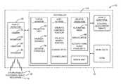
- FIG. 1is a diagram of a steering-control system in accordance with one embodiment
- FIG. 2is a traffic-scenario encountered by the system of FIG. 1 in accordance with one embodiment.
- FIG. 1illustrates a non-limiting example of a steering-control system 10 , hereafter referred to as the system 10 , which is generally intended for operating an automated vehicle such as a host-vehicle 12 .
- the non-limiting examples presented hereinare generally directed to instances when the host-vehicle 12 is being operated in an automated-mode 14 , i.e. a fully autonomous mode, where a human operator (not shown) of the host-vehicle 12 may do nothing more than designate a destination to operate the host-vehicle 12 .
- the teachings presented hereinare useful when the host-vehicle 12 is operated in a manual-mode 16 where the host-vehicle 12 is operated for the most part by the human operator, and the degree or level of automation may be little more than providing route guidance to the human operator who is generally in control of the steering, accelerator, and brakes of the host-vehicle 12 . That is, in the manual-mode 16 the system 10 may assist and/or only intervene with the operation of the host-vehicle 12 by the human operator if necessary to avoid a collision with, for example, an other-vehicle 18 .
- the system 10includes an object-detector 20 which is deemed suitable for use on the host-vehicle 12 as the object-detector 20 is generally designed to operate over the range of ambient temperatures experienced by the host-vehicle 12 , as will be recognized by those in the art.
- the object-detector 20is, in one respect, used by a controller 22 of the system 10 to detect the other-vehicle 18 when the other-vehicle 18 is approaching the host-vehicle 12 .
- the object-detector 20is not limited to only this use as will become evident below.
- the other-vehicle 18may approach the host-vehicle 12 from behind ( FIG.
- the controller 22is in communication with the object-detector 20 and is adapted to operate the host-vehicle via the vehicle-controls on a full-time basis (i.e. autonomous operation) or on a temporary basis as needed to assist the human operator.
- the communication between the object-detector 20 and the controller 22may be by way of wires, wireless communication, or optical-fiber, as will be recognized by those in the art.
- the controller 22may include a processor (not specifically shown) such as a microprocessor or other control circuitry such as analog and/or digital control circuitry including an application specific integrated circuit (ASIC) for processing data as should be evident to those in the art.
- ASICapplication specific integrated circuit
- the controller 22may include memory (not specifically shown), including non-volatile memory, such as electrically erasable programmable read-only memory (EEPROM) for storing one or more routines, thresholds, and captured data.
- EEPROMelectrically erasable programmable read-only memory
- the one or more routinesmay be executed by the processor to perform steps for determining, for example, the relative-location 36 based on signals received by the controller 22 for operating the host-vehicle 12 as described herein.
- the function of the object-detector 20may be provided by, but is not limited to, a camera 24 , a radar-unit 26 , a lidar 28 , or any combination thereof.
- the function of the object-detector 20may also be provided or supplemented by a transceiver (not shown) configured for wireless communications 30 such as vehicle-to-infrastructure (V2I) communications, vehicle-to-vehicle (V2V) communications, and/or vehicle-to-pedestrian (V2P) communications, which may be generically referred to as V2X communications, as will be recognized by those in the art.
- V2Ivehicle-to-infrastructure
- V2Vvehicle-to-vehicle
- V2Pvehicle-to-pedestrian
- FIG. 2illustrates a non-limiting example of a traffic-scenario 32 that the host-vehicle 12 may encounter.
- the host-vehicle 12is traveling along the travel-lane 38 of a roadway 40 , and is about to be passed by the other-vehicle 18 approaching from behind the host-vehicle 12 .
- the system 10or more specifically the controller 22 , may determine that the other-vehicle 18 is now (at time T 1 ), or is likely in the future (e.g. at time T 2 ) to be, too close to the host-vehicle 12 and thereby risks a collision with the host-vehicle 12 .
- the controller 22is generally configured to steer the host-vehicle 12 away from the other-vehicle 18 .
- How to steer awayis preferably limited to keep the host-vehicle 12 in the travel-lane 38 , but exiting the travel-lane 38 is a secondary or back-up action if staying in the travel-lane 38 is ill-advised.
- the controller 22In order for the controller 22 to be able to determine where the host-vehicle 12 is or should be positioned on the roadway 40 or the travel-lane 38 , the controller 22 also uses the object-detector 20 to detect a stationary-object 42 ( FIG. 1 ) that defines the boundaries or extents of the roadway 40 traveled by the host-vehicle 12 .
- the stationary-object 42may be one or more of, but is not limited to, a lane-marking 44 , a road-sign 46 , a guardrail 48 , a shoulder 52 , and a road-edge 54 .
- the controller 22is generally configured to steer the host-vehicle 12 towards a centered-position 60 of the travel-lane 38 of the roadway 40 when a projected-path 62 of the other-vehicle 18 approaches the host-vehicle 12 to a minimum-distance 64 (measured between the other-vehicle 18 and the host-vehicle 12 ) that is greater than a distance-threshold 66 , one meter (1 m) for example.
- the host-vehicle 12generally remains in the center of the travel-lane 38 as long as the other-vehicle 18 is actually not too close, and is projected to not become too close. Contrariwise, if the other-vehicle 18 is weaving and/or is not centered in the adjacent-lane 70 , as shown in FIG. 2 , the controller 22 is generally configured to avoid the host-vehicle 12 being too close to the other-vehicle 18 .
- the controller 22is further configured to steer the host-vehicle 12 towards a biased-position 68 of the travel-lane 38 to increase the minimum-distance 64 when the projected-path 62 approaches the host-vehicle 12 to less than the distance-threshold 66 if the host-vehicle 12 remains in the centered-position 60 .
- FIG. 2may be interpreted to suggest that the host-vehicle 12 will only move as far as the road-edge 54 to increase the distance or clearance between the host-vehicle 12 and the other-vehicle 18 , it is contemplated that the host-vehicle 12 may operate partially (e.g. two-wheels) on the shoulder 52 if the speed of the host-vehicle 12 and the perceived conditions of the shoulder 52 would make doing so relatively safe.
- the object-detector 20While traveling in the biased-position 68 , the object-detector 20 is used to take into account the presence of, for example, the lane-marking 44 , the road-sign 46 , the guardrail 48 , the shoulder 52 , the road-edge 54 , and/or any other object proximate to the travel-lane 38 such as a pedestrian 72 .
- the pedestrian 72may be detected by, for example, the camera 24 or V2P communications.
- the controller 22may be further configured to change a speed 74 of the host-vehicle 12 when the projected-path 62 approaches or is predicted to approach the host-vehicle 12 to a minimum-distance 64 that is less than the distance-threshold 66 if the host-vehicle remains in the biased-position 68 and the speed 74 remains unchanged.
- the host-vehicle 12may time a slow-down to correspond to when the weaving pattern of the other-vehicle 18 places the other-vehicle 18 in a centered or left-of-center position in the adjacent-lane 70 and/or so the other-vehicle 18 passes by more quickly.
- the host-vehicle 12may speed-up to get to an exit-ramp (not shown) before the other-vehicle 18 begins pass.
- the controller 22may be further configured to steer the host-vehicle 12 to change the travel-lane 38 of the host-vehicle 12 when the projected-path 62 approaches the host-vehicle 12 to less than the distance-threshold 66 if the host-vehicle 12 remains in the biased-position 68 . That is, the controller 22 may steer the host-vehicle to affect a lane-change if moving to biased-position 68 is insufficient. With reference to FIG. 2 , this may result in the host-vehicle 12 steering completely onto the shoulder 52 , i.e. all four wheels on the shoulder.
- the host-vehicle 12may change lanes to the right lane to avoid being too close to the other-vehicle 18 .
- the controllermay activate the horn of the host-vehicle 12 , and/or flash the headlights and/or tail lights of the host-vehicle 12 in an attempt to get the attention the operator of the other-vehicle 18 and/or warn any other-vehicles (not shown) that the other-vehicle 18 is driving erratically.
- a steering-control system(the system 10 ), a controller 22 for the system 10 and a method of operating the system 10 is provided.
- the preferenceis for the host-vehicle 12 to move to a position in the travel-lane 38 that is still within the travel-lane 38 as illustrated in FIG. 2 rather than make a lane change as the first action taken when the other-vehicle 18 gets too close, i.e. closer than the distance-threshold 66 .
- the host-vehicle 12may executive a lane change.
Landscapes
- Engineering & Computer Science (AREA)
- Physics & Mathematics (AREA)
- General Physics & Mathematics (AREA)
- Business, Economics & Management (AREA)
- Automation & Control Theory (AREA)
- Accounting & Taxation (AREA)
- Finance (AREA)
- Theoretical Computer Science (AREA)
- Transportation (AREA)
- Mechanical Engineering (AREA)
- Radar, Positioning & Navigation (AREA)
- Remote Sensing (AREA)
- Aviation & Aerospace Engineering (AREA)
- Combustion & Propulsion (AREA)
- Chemical & Material Sciences (AREA)
- Artificial Intelligence (AREA)
- Health & Medical Sciences (AREA)
- Strategic Management (AREA)
- Economics (AREA)
- Marketing (AREA)
- Development Economics (AREA)
- General Business, Economics & Management (AREA)
- Evolutionary Computation (AREA)
- Medical Informatics (AREA)
- Game Theory and Decision Science (AREA)
- General Engineering & Computer Science (AREA)
- Computational Linguistics (AREA)
- General Health & Medical Sciences (AREA)
- Audiology, Speech & Language Pathology (AREA)
- Traffic Control Systems (AREA)
- Management, Administration, Business Operations System, And Electronic Commerce (AREA)
- Control Of Driving Devices And Active Controlling Of Vehicle (AREA)
Abstract
Description
Claims (4)
Priority Applications (4)
| Application Number | Priority Date | Filing Date | Title |
|---|---|---|---|
| US15/175,494US9836977B1 (en) | 2016-06-07 | 2016-06-07 | Automated vehicle steering control system with lane position bias |
| EP17173926.1AEP3254938B1 (en) | 2016-06-07 | 2017-06-01 | Automated vehicle steering control system with lane position bias |
| CN201710418757.6ACN107472359B (en) | 2016-06-07 | 2017-06-06 | Using the automotive vehicle steering control system of lane position deviation |
| US15/664,134US20170352087A1 (en) | 2016-06-07 | 2017-07-31 | Estimating merchandise uniqueness |
Applications Claiming Priority (1)
| Application Number | Priority Date | Filing Date | Title |
|---|---|---|---|
| US15/175,494US9836977B1 (en) | 2016-06-07 | 2016-06-07 | Automated vehicle steering control system with lane position bias |
Related Child Applications (1)
| Application Number | Title | Priority Date | Filing Date |
|---|---|---|---|
| US15/664,134ContinuationUS20170352087A1 (en) | 2016-06-07 | 2017-07-31 | Estimating merchandise uniqueness |
Publications (2)
| Publication Number | Publication Date |
|---|---|
| US9836977B1true US9836977B1 (en) | 2017-12-05 |
| US20170352278A1 US20170352278A1 (en) | 2017-12-07 |
Family
ID=59021318
Family Applications (2)
| Application Number | Title | Priority Date | Filing Date |
|---|---|---|---|
| US15/175,494ActiveUS9836977B1 (en) | 2016-06-07 | 2016-06-07 | Automated vehicle steering control system with lane position bias |
| US15/664,134AbandonedUS20170352087A1 (en) | 2016-06-07 | 2017-07-31 | Estimating merchandise uniqueness |
Family Applications After (1)
| Application Number | Title | Priority Date | Filing Date |
|---|---|---|---|
| US15/664,134AbandonedUS20170352087A1 (en) | 2016-06-07 | 2017-07-31 | Estimating merchandise uniqueness |
Country Status (3)
| Country | Link |
|---|---|
| US (2) | US9836977B1 (en) |
| EP (1) | EP3254938B1 (en) |
| CN (1) | CN107472359B (en) |
Cited By (5)
| Publication number | Priority date | Publication date | Assignee | Title |
|---|---|---|---|---|
| CN108876509A (en)* | 2018-05-11 | 2018-11-23 | 上海赢科信息技术有限公司 | Utilize the method and system of POI analysis user tag |
| US20200369271A1 (en)* | 2016-12-21 | 2020-11-26 | Samsung Electronics Co., Ltd. | Electronic apparatus for determining a dangerous situation of a vehicle and method of operating the same |
| US20210370946A1 (en)* | 2018-02-20 | 2021-12-02 | Nissan Motor Co., Ltd. | Automated lane change control method and automated lane change control device |
| US11193782B2 (en)* | 2017-03-27 | 2021-12-07 | Mitsubishi Electric Corporation | Vehicle position estimation apparatus |
| US20220203992A1 (en)* | 2019-05-15 | 2022-06-30 | Nissan Motor Co., Ltd. | Traveling Control Method and Traveling Control Device for Vehicle |
Families Citing this family (6)
| Publication number | Priority date | Publication date | Assignee | Title |
|---|---|---|---|---|
| CN108238101A (en)* | 2017-12-26 | 2018-07-03 | 潍柴动力股份有限公司 | For the automatic control system and autocontrol method of sweeper |
| US11143760B2 (en) | 2018-02-19 | 2021-10-12 | Motional Ad Llc | Object-detector configuration based on human-override of automated vehicle control |
| DE102019104138B4 (en)* | 2018-02-19 | 2020-10-29 | Delphi Technologies, Llc | Object detector configuration based on human override of an automatic vehicle control |
| US10935977B2 (en)* | 2018-06-28 | 2021-03-02 | Aptiv Technologies Limited | Lane assignment system |
| DE102019218504A1 (en)* | 2019-01-30 | 2020-07-30 | Mando Corporation | DRIVER ASSISTANCE SYSTEM AND TAX METHOD THEREFOR |
| WO2022204991A1 (en)* | 2021-03-30 | 2022-10-06 | 京东方科技集团股份有限公司 | Real-time audio/video recommendation method and apparatus, device, and computer storage medium |
Citations (6)
| Publication number | Priority date | Publication date | Assignee | Title |
|---|---|---|---|---|
| US5959572A (en)* | 1997-03-31 | 1999-09-28 | Nissan Motor Co., Ltd. | Vehicle follow-up control apparatus |
| US6311119B2 (en) | 1997-07-07 | 2001-10-30 | Honda Giken Kojyo Kabushiki Kaisha | Vehicle control system |
| US20020198632A1 (en)* | 1997-10-22 | 2002-12-26 | Breed David S. | Method and arrangement for communicating between vehicles |
| US20100082195A1 (en)* | 2008-06-20 | 2010-04-01 | Gm Global Technology Operations, Inc. | Method to adaptively control vehicle operation using an autonomic vehicle control system |
| US8260491B2 (en) | 2009-07-31 | 2012-09-04 | Systems and Advances Technologoes Engineering S.r.l. | Road vehicle driver behaviour analysis method |
| US20130238181A1 (en) | 2012-03-12 | 2013-09-12 | Toyota Motor Eng. & Man. North America (Tema) | On-board vehicle path prediction using processed sensor information |
Family Cites Families (4)
| Publication number | Priority date | Publication date | Assignee | Title |
|---|---|---|---|---|
| ATE519647T1 (en)* | 2006-06-11 | 2011-08-15 | Volvo Technology Corp | METHOD AND DEVICE FOR USING AN AUTOMATED LANE KEEPING SYSTEM FOR MAINTAINING SIDE VEHICLE DISTANCE |
| DE102007015879A1 (en)* | 2007-04-02 | 2008-10-30 | Robert Bosch Gmbh | Method and device for controlling a driver assistance system |
| US9809219B2 (en)* | 2014-01-29 | 2017-11-07 | Continental Automotive Systems, Inc. | System for accommodating a pedestrian during autonomous vehicle operation |
| DE102015015302A1 (en)* | 2015-11-27 | 2016-05-12 | Daimler Ag | Method for partially or fully autonomous operation of a vehicle and driver assistance device |
- 2016
- 2016-06-07USUS15/175,494patent/US9836977B1/enactiveActive
- 2017
- 2017-06-01EPEP17173926.1Apatent/EP3254938B1/enactiveActive
- 2017-06-06CNCN201710418757.6Apatent/CN107472359B/enactiveActive
- 2017-07-31USUS15/664,134patent/US20170352087A1/ennot_activeAbandoned
Patent Citations (6)
| Publication number | Priority date | Publication date | Assignee | Title |
|---|---|---|---|---|
| US5959572A (en)* | 1997-03-31 | 1999-09-28 | Nissan Motor Co., Ltd. | Vehicle follow-up control apparatus |
| US6311119B2 (en) | 1997-07-07 | 2001-10-30 | Honda Giken Kojyo Kabushiki Kaisha | Vehicle control system |
| US20020198632A1 (en)* | 1997-10-22 | 2002-12-26 | Breed David S. | Method and arrangement for communicating between vehicles |
| US20100082195A1 (en)* | 2008-06-20 | 2010-04-01 | Gm Global Technology Operations, Inc. | Method to adaptively control vehicle operation using an autonomic vehicle control system |
| US8260491B2 (en) | 2009-07-31 | 2012-09-04 | Systems and Advances Technologoes Engineering S.r.l. | Road vehicle driver behaviour analysis method |
| US20130238181A1 (en) | 2012-03-12 | 2013-09-12 | Toyota Motor Eng. & Man. North America (Tema) | On-board vehicle path prediction using processed sensor information |
Cited By (7)
| Publication number | Priority date | Publication date | Assignee | Title |
|---|---|---|---|---|
| US20200369271A1 (en)* | 2016-12-21 | 2020-11-26 | Samsung Electronics Co., Ltd. | Electronic apparatus for determining a dangerous situation of a vehicle and method of operating the same |
| US11193782B2 (en)* | 2017-03-27 | 2021-12-07 | Mitsubishi Electric Corporation | Vehicle position estimation apparatus |
| US20210370946A1 (en)* | 2018-02-20 | 2021-12-02 | Nissan Motor Co., Ltd. | Automated lane change control method and automated lane change control device |
| US11440549B2 (en)* | 2018-02-20 | 2022-09-13 | Nissan Motor Co., Ltd. | Automated lane change control method and automated lane change control device |
| CN108876509A (en)* | 2018-05-11 | 2018-11-23 | 上海赢科信息技术有限公司 | Utilize the method and system of POI analysis user tag |
| US20220203992A1 (en)* | 2019-05-15 | 2022-06-30 | Nissan Motor Co., Ltd. | Traveling Control Method and Traveling Control Device for Vehicle |
| US11447136B2 (en)* | 2019-05-15 | 2022-09-20 | Nissan Motor Co., Ltd. | Traveling control method and traveling control device for vehicle |
Also Published As
| Publication number | Publication date |
|---|---|
| CN107472359A (en) | 2017-12-15 |
| US20170352278A1 (en) | 2017-12-07 |
| EP3254938B1 (en) | 2019-04-24 |
| EP3254938A1 (en) | 2017-12-13 |
| CN107472359B (en) | 2019-09-17 |
| US20170352087A1 (en) | 2017-12-07 |
Similar Documents
| Publication | Publication Date | Title |
|---|---|---|
| US9836977B1 (en) | Automated vehicle steering control system with lane position bias | |
| US10345814B2 (en) | Control system and control method for guiding a motor vehicle along a path | |
| US10246088B2 (en) | Control system and control method for guiding a motor vehicle along a path and for avoiding a collision with another motor vehicle | |
| US11087624B2 (en) | Safe-to-proceed system for an automated vehicle | |
| US10037696B2 (en) | Cooperative automated vehicle system | |
| US20170008519A1 (en) | Automated vehicle with erratic other vehicle avoidance | |
| US9989966B2 (en) | Intersection cross-walk navigation system for automated vehicles | |
| EP2803547B1 (en) | Collision mitigation apparatus | |
| EP3444168B1 (en) | Automated guidance system | |
| US20170349181A1 (en) | Lane management system for an automated vehicle | |
| JP6582936B2 (en) | Route generator, automatic travel control system | |
| EP3418162A1 (en) | Automated vehicle lane-keeping system | |
| EP3471077B1 (en) | Automated vehicle safety system that protects pedestrians | |
| CN105599767A (en) | Roundabout detecting arrangement | |
| JP6551214B2 (en) | Lane departure warning device and lane departure warning method | |
| JP2019153052A (en) | Collision determination apparatus | |
| KR20210004799A (en) | Method for autonomously operating vehicle, controller device for vehicle, and vehicle | |
| EP3640121A1 (en) | Vehicle lane-bias system and method | |
| US20180158336A1 (en) | Method and device for operating a vehicle | |
| CN112829748A (en) | Lane change assist apparatus, vehicle system including the same, and method thereof | |
| JP6520691B2 (en) | Lane deviation warning device and lane deviation warning method | |
| KR101114043B1 (en) | Method for Judging a Driving In Self-Lane for Vehicle | |
| US12304467B2 (en) | Driving assist device |
Legal Events
| Date | Code | Title | Description |
|---|---|---|---|
| AS | Assignment | Owner name:DELPHI TECHNOLOGIES, INC., MICHIGAN Free format text:ASSIGNMENT OF ASSIGNORS INTEREST;ASSIGNORS:CASHLER, ROBERT J.;PRASAD, PREMCHAND KRISHNA;SAMIEI, EHSAN;SIGNING DATES FROM 20160601 TO 20160606;REEL/FRAME:038830/0932 | |
| STCF | Information on status: patent grant | Free format text:PATENTED CASE | |
| AS | Assignment | Owner name:APTIV TECHNOLOGIES LIMITED, BARBADOS Free format text:ASSIGNMENT OF ASSIGNORS INTEREST;ASSIGNOR:DELPHI TECHNOLOGIES INC.;REEL/FRAME:047143/0874 Effective date:20180101 | |
| MAFP | Maintenance fee payment | Free format text:PAYMENT OF MAINTENANCE FEE, 4TH YEAR, LARGE ENTITY (ORIGINAL EVENT CODE: M1551); ENTITY STATUS OF PATENT OWNER: LARGE ENTITY Year of fee payment:4 | |
| AS | Assignment | Owner name:APTIV TECHNOLOGIES (2) S.A R.L., LUXEMBOURG Free format text:ENTITY CONVERSION;ASSIGNOR:APTIV TECHNOLOGIES LIMITED;REEL/FRAME:066746/0001 Effective date:20230818 Owner name:APTIV MANUFACTURING MANAGEMENT SERVICES S.A R.L., LUXEMBOURG Free format text:MERGER;ASSIGNOR:APTIV TECHNOLOGIES (2) S.A R.L.;REEL/FRAME:066566/0173 Effective date:20231005 Owner name:APTIV TECHNOLOGIES AG, SWITZERLAND Free format text:ASSIGNMENT OF ASSIGNORS INTEREST;ASSIGNOR:APTIV MANUFACTURING MANAGEMENT SERVICES S.A R.L.;REEL/FRAME:066551/0219 Effective date:20231006 | |
| MAFP | Maintenance fee payment | Free format text:PAYMENT OF MAINTENANCE FEE, 8TH YEAR, LARGE ENTITY (ORIGINAL EVENT CODE: M1552); ENTITY STATUS OF PATENT OWNER: LARGE ENTITY Year of fee payment:8 |