US9835327B2 - Gas burner for cooking appliances - Google Patents
Gas burner for cooking appliancesDownload PDFInfo
- Publication number
- US9835327B2 US9835327B2US12/309,103US30910307AUS9835327B2US 9835327 B2US9835327 B2US 9835327B2US 30910307 AUS30910307 AUS 30910307AUS 9835327 B2US9835327 B2US 9835327B2
- Authority
- US
- United States
- Prior art keywords
- burner
- ring
- shaped
- catalytic activity
- chamber
- Prior art date
- Legal status (The legal status is an assumption and is not a legal conclusion. Google has not performed a legal analysis and makes no representation as to the accuracy of the status listed.)
- Expired - Fee Related, expires
Links
- 238000010411cookingMethods0.000titleclaimsabstractdescription8
- 230000003197catalytic effectEffects0.000claimsabstractdescription35
- 239000000463materialSubstances0.000claimsabstractdescription32
- 239000000203mixtureSubstances0.000claimsabstractdescription26
- 229910052751metalInorganic materials0.000claimsabstractdescription10
- 239000002184metalSubstances0.000claimsabstractdescription10
- 229910001092metal group alloyInorganic materials0.000claimsabstractdescription9
- 239000003054catalystSubstances0.000claimsdescription11
- 230000004913activationEffects0.000claimsdescription5
- 229910052784alkaline earth metalInorganic materials0.000claimsdescription5
- 150000001342alkaline earth metalsChemical class0.000claimsdescription5
- 229910000838Al alloyInorganic materials0.000claimsdescription4
- 241000255893PyralidaeSpecies0.000claimsdescription4
- PNEYBMLMFCGWSK-UHFFFAOYSA-Naluminium oxideInorganic materials[O-2].[O-2].[O-2].[Al+3].[Al+3]PNEYBMLMFCGWSK-UHFFFAOYSA-N0.000claimsdescription4
- 238000007654immersionMethods0.000claimsdescription3
- 229910044991metal oxideInorganic materials0.000claimsdescription3
- 150000004706metal oxidesChemical class0.000claimsdescription3
- 229910052593corundumInorganic materials0.000claims2
- 229910003455mixed metal oxideInorganic materials0.000claims2
- 230000002093peripheral effectEffects0.000claims2
- 238000011144upstream manufacturingMethods0.000claims2
- 229910001845yogo sapphireInorganic materials0.000claims2
- 239000000758substrateSubstances0.000abstractdescription3
- 239000012018catalyst precursorSubstances0.000abstract1
- 238000002485combustion reactionMethods0.000description21
- 239000007789gasSubstances0.000description9
- 230000001473noxious effectEffects0.000description7
- MWUXSHHQAYIFBG-UHFFFAOYSA-Nnitrogen oxideInorganic materialsO=[N]MWUXSHHQAYIFBG-UHFFFAOYSA-N0.000description5
- 238000010586diagramMethods0.000description4
- 239000002245particleSubstances0.000description4
- BASFCYQUMIYNBI-UHFFFAOYSA-NplatinumChemical compound[Pt]BASFCYQUMIYNBI-UHFFFAOYSA-N0.000description4
- 239000000126substanceSubstances0.000description4
- 238000006555catalytic reactionMethods0.000description3
- 239000011248coating agentSubstances0.000description3
- 238000000576coating methodMethods0.000description3
- KDLHZDBZIXYQEI-UHFFFAOYSA-NPalladiumChemical compound[Pd]KDLHZDBZIXYQEI-UHFFFAOYSA-N0.000description2
- 229910010293ceramic materialInorganic materials0.000description2
- 238000004140cleaningMethods0.000description2
- 229910052878cordieriteInorganic materials0.000description2
- JSKIRARMQDRGJZ-UHFFFAOYSA-Ndimagnesium dioxido-bis[(1-oxido-3-oxo-2,4,6,8,9-pentaoxa-1,3-disila-5,7-dialuminabicyclo[3.3.1]nonan-7-yl)oxy]silaneChemical compound[Mg++].[Mg++].[O-][Si]([O-])(O[Al]1O[Al]2O[Si](=O)O[Si]([O-])(O1)O2)O[Al]1O[Al]2O[Si](=O)O[Si]([O-])(O1)O2JSKIRARMQDRGJZ-UHFFFAOYSA-N0.000description2
- 238000012423maintenanceMethods0.000description2
- 238000004519manufacturing processMethods0.000description2
- 239000007769metal materialSubstances0.000description2
- 229910052697platinumInorganic materials0.000description2
- 239000012855volatile organic compoundSubstances0.000description2
- UGFAIRIUMAVXCW-UHFFFAOYSA-NCarbon monoxideChemical class[O+]#[C-]UGFAIRIUMAVXCW-UHFFFAOYSA-N0.000description1
- 229910052782aluminiumInorganic materials0.000description1
- 229910002090carbon oxideInorganic materials0.000description1
- 238000006243chemical reactionMethods0.000description1
- 239000000567combustion gasSubstances0.000description1
- 238000010276constructionMethods0.000description1
- 230000008021depositionEffects0.000description1
- 230000000694effectsEffects0.000description1
- 238000006056electrooxidation reactionMethods0.000description1
- 230000008030eliminationEffects0.000description1
- 238000003379elimination reactionMethods0.000description1
- 239000000446fuelSubstances0.000description1
- 229910052741iridiumInorganic materials0.000description1
- GKOZUEZYRPOHIO-UHFFFAOYSA-Niridium atomChemical compound[Ir]GKOZUEZYRPOHIO-UHFFFAOYSA-N0.000description1
- 238000000034methodMethods0.000description1
- 230000003647oxidationEffects0.000description1
- 238000007254oxidation reactionMethods0.000description1
- 230000033116oxidation-reduction processEffects0.000description1
- 229910052763palladiumInorganic materials0.000description1
- 239000002243precursorSubstances0.000description1
- 230000037452primingEffects0.000description1
- 229910052703rhodiumInorganic materials0.000description1
- 239000010948rhodiumSubstances0.000description1
- MHOVAHRLVXNVSD-UHFFFAOYSA-Nrhodium atomChemical compound[Rh]MHOVAHRLVXNVSD-UHFFFAOYSA-N0.000description1
Images


Classifications
- F—MECHANICAL ENGINEERING; LIGHTING; HEATING; WEAPONS; BLASTING
- F23—COMBUSTION APPARATUS; COMBUSTION PROCESSES
- F23D—BURNERS
- F23D14/00—Burners for combustion of a gas, e.g. of a gas stored under pressure as a liquid
- F23D14/02—Premix gas burners, i.e. in which gaseous fuel is mixed with combustion air upstream of the combustion zone
- F23D14/04—Premix gas burners, i.e. in which gaseous fuel is mixed with combustion air upstream of the combustion zone induction type, e.g. Bunsen burner
- F23D14/06—Premix gas burners, i.e. in which gaseous fuel is mixed with combustion air upstream of the combustion zone induction type, e.g. Bunsen burner with radial outlets at the burner head
- F—MECHANICAL ENGINEERING; LIGHTING; HEATING; WEAPONS; BLASTING
- F23—COMBUSTION APPARATUS; COMBUSTION PROCESSES
- F23D—BURNERS
- F23D2900/00—Special features of, or arrangements for burners using fluid fuels or solid fuels suspended in a carrier gas
- F23D2900/00001—Special features of, or arrangements for burners using fluid fuels or solid fuels suspended in a carrier gas local catalytic coatings applied to burner surfaces
Definitions
- the present inventionrelates to gas-fired cooking appliances, in particular of household type, and regards specifically the burners for such appliances.
- burnersi.e., burners in which a gas-air mixture is passed through a structure constructed or coated with a material that produces a flame-less combustion of the mixture.
- These burnersact substantially as filters designed to absorb the combustion gases or produce an exothermic oxidation of the same, so as to eliminate the noxious substances resulting from combustion.
- GB 2,347,362discloses a burner of this type, with a structure made of ceramic material, such as cordierite, and the catalyst includes at least one metal selected from among platinum, rhodium, palladium and iridium, with the preferred metal being platinum.
- Cordieriteis chosen because it displays a surface porosity necessary to achieve the deposition of the catalyst, thus increasing the active surface in the elimination of noxious gases.
- the construction of catalytic burners with a structure of ceramic materialhas not proved to be advantageous in household applications for various reasons, such as, for example, the fragility of the material, which is scarcely suitable for an object, such as a burner, consisting of a plurality of pieces which need to be frequently disassembled for cleaning and maintenance.
- the catalytic materialis applied to only one part of the surface of the burner, particularly on the outlet surface of the structure, as it is believed it should act on the gaseous products of combustion, that is, after the combustion has occurred.
- JP 07091622A similar solution is disclosed in JP 07091622, where the surfaces that come into contact with gas emissions are coated with catalyzing material to produce an oxidation-reduction of the same emissions.
- catalytic burnersact by eliminating the noxious substances produced by combustion because, as already mentioned, the catalyst is made to act downstream of combustion.
- the main advantage obtainable with the use of catalytic burnershas been to facilitate the maintenance of the cleanness of the surfaces in contact with the flame, with the so-called self-cleaning burners. Examples of catalytic burners of this type are described in U.S. Pat. No. 3,817,689 and U.S. Pat. No. 3,921,913.
- the main objective of this inventionis to provide a burner for cooking appliances, particularly of household type, that effectively resolves the problem of eliminating the noxious products of combustion, by bringing the air-gas mixture in contact with a catalytic surface before combustion takes place.
- Another objective of the inventionis to provide a burner of catalytic type that offers a greater thermal efficiency and reduces the energy required for combustion.
- a further objective of the inventionis to provide a burner of catalytic type whose structure is realized with metal materials suitable for use in household cooking appliances, particularly aluminium alloys, which ensure the required mechanical sturdiness.
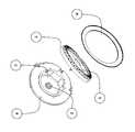
- FIG. 1is an exploded perspective view of a burner structure according to the invention
- FIG. 2is a schematic cross section of the burner structure of FIG. 1 ;
- FIG. 3is a diagram illustrating the energy required to activate the catalytic reaction in the combustion process
- FIG. 4is a diagram showing the quantities of catalyst that are activated to generate combustion as a function of the energy supplied.
- FIGS. 5A and 5Beach show a cross sectional view of a surface of the burner.
- a burner according to the inventionhas a structure ( FIG. 1 ) that substantially consists of: a body 10 defining a chamber 12 , wherein an injector 14 inputs the gas that upon mixing with the air forms the combustible air-gas mixture; a ring-shaped element 16 on the upper side of the body, having a periphery provided with the combustion mixture outlet ports 18 , and a burner-covering circular plate 20 .
- At least the ring-shaped element 16is made of a metal or metal alloy, preferably an aluminium alloy such as Pyral (96% Al, 2% Mg, 2% Si), a material widely used in the production of gas-fired burners.
- a metal or metal alloypreferably an aluminium alloy such as Pyral (96% Al, 2% Mg, 2% Si), a material widely used in the production of gas-fired burners.
- the body 10 and the circular platecan also be made from metal material or a metal alloy.
- the combustible mixtureissues from the outlet ports 18 and is ignited by an ignition device (non shown), forming a crown of flames around the periphery of the burner.
- the heat generated by combustionis transmitted to the whole structure of the burner, which reaches a high steady-state temperature (in the order of several hundred degrees Celsius).
- At least the ring 16( FIG. 2 ) is coated with a thin layer of material having a catalytic activity, for the purpose of reacting with the gas-air mixture that flows out along the surface of the ring.
- the thin layer of material 110 having catalytic activityis formed on a surface 120 of the burner.
- This surface 120may be at least an underside surface of the burner-covering plate. As mentioned above, this surface 120 may also be on the ring 16 . This surface may also be at least an internal surface of the burner body 10 .
- a support layer 130may be formed on the surface 120 .
- the layer 130may also be a buffer layer or substrate.
- the coating material having catalytic activityis made up of metal oxides, either simple or mixed, in particular oxides of alkaline or alkaline-earth metals, that are coated on the burner surfaces by means of known procedures, for example by immersion in a catalyst bath.
- the surfacescan be, if necessary, prepared by forming on them the support layer 130 that serves as suitable precursor of the catalyst.
- the surfacescan be prepared by coating them with an alumina layer AI2O3, for example by electrochemical oxidation, so as to form a buffer layer or substrate.
- the catalysts usedwhich are active at the typical temperatures of household gas burners (200-4000 C), enable the gas-air combustible mixture to burn with a better combustion, reducing the production of noxious gases, while lowering the quantity of energy required for combustion, with the result of improving its efficiency and consequently reducing the output of noxious gases.
- the contact of the combustible mixture with the catalyst-coated and activated burner surfaceshas the effect of preoxidizing the air-gas mixture within the burner body.
- the combustion reactionrequires considerable quantity of activation energy. This activation energy is considerably reduced in a burner coated with catalyzing material according to the invention.
- the use of the catalystmakes it possible to lower the priming energy necessary to activate the combustion process.
- the reduction of the combustion activation energyis due to the fact that the catalytic reaction brings about an increase in the quantity of fuel particles that acquire the energy necessary for combustion.
- the quantity of particles provided with such energyis represented by area A in the diagram of FIG. 4
- area Brepresents the additional quantity of particles that are activated by the catalytic reaction to generate combustion.
- area Crepresents the quantity of particles that do not have sufficient energy to take part in the reaction.
Landscapes
- Engineering & Computer Science (AREA)
- Chemical & Material Sciences (AREA)
- Combustion & Propulsion (AREA)
- Mechanical Engineering (AREA)
- General Engineering & Computer Science (AREA)
- Catalysts (AREA)
- Gas Burners (AREA)
Abstract
Description
The present invention relates to gas-fired cooking appliances, in particular of household type, and regards specifically the burners for such appliances.
As is well known, the combustion process that takes place in these appliances generates various noxious substances, such as nitrogen oxides (NOx), volatile organic compounds (VOC) and carbon oxides (CO and CO2).
The problem of eliminating or reducing these substances to improve the working conditions in cooking environments has been tackled for a long time with various technical solutions.
One of the known solutions provides for the use of so-called “catalytic” burners, i.e., burners in which a gas-air mixture is passed through a structure constructed or coated with a material that produces a flame-less combustion of the mixture. These burners act substantially as filters designed to absorb the combustion gases or produce an exothermic oxidation of the same, so as to eliminate the noxious substances resulting from combustion.
GB 2,347,362 discloses a burner of this type, with a structure made of ceramic material, such as cordierite, and the catalyst includes at least one metal selected from among platinum, rhodium, palladium and iridium, with the preferred metal being platinum. Cordierite is chosen because it displays a surface porosity necessary to achieve the deposition of the catalyst, thus increasing the active surface in the elimination of noxious gases. However, the construction of catalytic burners with a structure of ceramic material has not proved to be advantageous in household applications for various reasons, such as, for example, the fragility of the material, which is scarcely suitable for an object, such as a burner, consisting of a plurality of pieces which need to be frequently disassembled for cleaning and maintenance. In addition, the catalytic material is applied to only one part of the surface of the burner, particularly on the outlet surface of the structure, as it is believed it should act on the gaseous products of combustion, that is, after the combustion has occurred.
A similar solution is disclosed in JP 07091622, where the surfaces that come into contact with gas emissions are coated with catalyzing material to produce an oxidation-reduction of the same emissions.
The known catalytic burners act by eliminating the noxious substances produced by combustion because, as already mentioned, the catalyst is made to act downstream of combustion. Thus, the main advantage obtainable with the use of catalytic burners has been to facilitate the maintenance of the cleanness of the surfaces in contact with the flame, with the so-called self-cleaning burners. Examples of catalytic burners of this type are described in U.S. Pat. No. 3,817,689 and U.S. Pat. No. 3,921,913.
The main objective of this invention is to provide a burner for cooking appliances, particularly of household type, that effectively resolves the problem of eliminating the noxious products of combustion, by bringing the air-gas mixture in contact with a catalytic surface before combustion takes place.
Another objective of the invention is to provide a burner of catalytic type that offers a greater thermal efficiency and reduces the energy required for combustion.
A further objective of the invention is to provide a burner of catalytic type whose structure is realized with metal materials suitable for use in household cooking appliances, particularly aluminium alloys, which ensure the required mechanical sturdiness.
These and other objectives of the invention will be achieved with a burner as described hereunder and with specific reference to the appended claims.
The characteristics and advantages of the present invention will become clear from the following description, given by way of example and not by way of limitation, with reference to the accompanying drawings, wherein:
A burner according to the invention has a structure (FIG. 1 ) that substantially consists of: abody 10 defining achamber 12, wherein aninjector 14 inputs the gas that upon mixing with the air forms the combustible air-gas mixture; a ring-shaped element 16 on the upper side of the body, having a periphery provided with the combustionmixture outlet ports 18, and a burner-coveringcircular plate 20.
According to the invention, at least the ring-shaped element 16 is made of a metal or metal alloy, preferably an aluminium alloy such as Pyral (96% Al, 2% Mg, 2% Si), a material widely used in the production of gas-fired burners. Naturally, thebody 10 and the circular plate can also be made from metal material or a metal alloy.
As is well known, the combustible mixture issues from theoutlet ports 18 and is ignited by an ignition device (non shown), forming a crown of flames around the periphery of the burner. The heat generated by combustion is transmitted to the whole structure of the burner, which reaches a high steady-state temperature (in the order of several hundred degrees Celsius).
According to the invention, at least the ring16 (FIG. 2 ) is coated with a thin layer of material having a catalytic activity, for the purpose of reacting with the gas-air mixture that flows out along the surface of the ring.
As shown inFIG. 5A , the thin layer ofmaterial 110 having catalytic activity is formed on asurface 120 of the burner. Thissurface 120 may be at least an underside surface of the burner-covering plate. As mentioned above, thissurface 120 may also be on thering 16. This surface may also be at least an internal surface of theburner body 10. As shown inFIG. 5B , asupport layer 130 may be formed on thesurface 120. Thelayer 130 may also be a buffer layer or substrate.
The coating material having catalytic activity is made up of metal oxides, either simple or mixed, in particular oxides of alkaline or alkaline-earth metals, that are coated on the burner surfaces by means of known procedures, for example by immersion in a catalyst bath.
To obtain a suitable coating, the surfaces can be, if necessary, prepared by forming on them thesupport layer 130 that serves as suitable precursor of the catalyst. When the burner is made of Pyral, which has a compact surface with low porosity, the surfaces can be prepared by coating them with an alumina layer AI2O3, for example by electrochemical oxidation, so as to form a buffer layer or substrate.
The catalysts used, which are active at the typical temperatures of household gas burners (200-4000 C), enable the gas-air combustible mixture to burn with a better combustion, reducing the production of noxious gases, while lowering the quantity of energy required for combustion, with the result of improving its efficiency and consequently reducing the output of noxious gases. In fact, the contact of the combustible mixture with the catalyst-coated and activated burner surfaces has the effect of preoxidizing the air-gas mixture within the burner body.
The combustion reaction requires considerable quantity of activation energy. This activation energy is considerably reduced in a burner coated with catalyzing material according to the invention.
As shown in the diagram ofFIG. 3 , the use of the catalyst makes it possible to lower the priming energy necessary to activate the combustion process.
The reduction of the combustion activation energy is due to the fact that the catalytic reaction brings about an increase in the quantity of fuel particles that acquire the energy necessary for combustion. Normally, the quantity of particles provided with such energy is represented by area A in the diagram ofFIG. 4 , while area B represents the additional quantity of particles that are activated by the catalytic reaction to generate combustion. Finally, area C represents the quantity of particles that do not have sufficient energy to take part in the reaction.
Claims (26)
1. A burner for gas-fired cooking appliances, the burner comprising:
a burner body defining a chamber;
a burner-covering plate positioned above the burner body;
a ring-shaped burner element positioned between the burner body and the burner-covering plate, the ring-shaped burner element and the burner-covering plate defining an outlet between a periphery of the ring-shaped burner element and a periphery of the burner body; and
an injector for introducing gas into the chamber of the burner body wherein the flow of gas from the injector draws air into the chamber from a surrounding environment from an air inlet to form a combustible gas-air mixture within the chamber, the combustible gas-air mixture being conveyed into a space defined between the ring-shaped burner element and the burner-covering plate;
wherein at least the ring-shaped burner element is made of a metal or a metal alloy and is coated with a thin layer of material having catalytic activity,
wherein the ring-shaped burner is configured such that the combustible gas-air mixture is conveyed over the material having catalytic activity and reacts with the material having catalytic activity upstream of the outlet to form a pre-oxidized air-gas mixture within the chamber of the burner body, the outlet between the periphery of the ring-shaped burner element and the periphery of the burner body configured to allow the pre-oxidized air-gas mixture to exit the chamber of the burner body for ignition outside of the chamber, and
wherein the material having catalytic activity is one of simple metal oxides and mixed metal oxides.
2. The burner ofclaim 1 , wherein the material having catalytic activity is one of oxides of alkaline and oxides of alkaline-earth metals.
3. The burner ofclaim 1 , wherein the burner-covering plate is made of a metal or metal alloy, and at least an underside surface of the burner-covering plate is coated with a thin layer of the material having catalytic activity.
4. The burner ofclaim 3 , wherein the material having catalytic activity is one of oxides of alkaline and oxides of alkaline-earth metals.
5. The burner ofclaim 1 , wherein the burner body is made of a metal or metal alloy and at least an internal surface of the burner body is coated with a thin layer of the material having catalytic activity.
6. The burner ofclaim 5 , wherein the material having catalytic activity is one of oxides of alkaline and oxides of alkaline-earth metals.
7. The burner ofclaim 1 , wherein the burner is made of aluminum alloy.
8. The burner ofclaim 1 , wherein the burner is made of Pyral.
9. The burner ofclaim 1 , wherein the thin layer of material having catalytic activity is formed by immersion in a catalyst bath.
10. A burner for gas-fired cooking appliances, the burner comprising:
a burner body defining a chamber
a burner-covering plate positioned above the burner body;
a ring-shaped burner element positioned between the burner body and the burner-covering plate, the ring-shaped burner element and the burner-covering plate defining an outlet between a periphery of the ring-shaped burner element and a periphery of the burner body; and
an injector for introducing gas into the chamber of the burner body wherein the flow of gas from the injector draws air into the chamber from a surrounding environment through an air inlet to form a combustible gas-air mixture within the chamber, the combustible gas-air mixture being conveyed into a space defined between the ring-shaped burner element and the burner-covering plate;
wherein at least the ring-shaped burner element is made of a metal or a metal alloy and is coated with a thin layer of material having catalytic activity,
wherein the burner-covering plate is made of a metal or metal alloy, and at least an underside surface of the burner-covering plate is coated with a thin layer of material having catalytic activity,
wherein the ring-shaped burner is configured such that the combustible gas-air mixture is conveyed along the underside surface of the burner-covering plate and along a surface of the ring-shaped burner element and reacts with the materials having catalytic activity upstream of the outlet to form a pre-oxidized air-gas mixture in the chamber of the burner body, the outlet between the periphery of the ring-shaped burner element and the periphery of the burner body configured to allow the pre-oxidize air-gas mixture to exit the chamber of the burner body for ignition outside of the chamber, and
wherein the thin layer of material having catalytic activity on the ring-shaped burner element and the underside surface of the burner-covering plate is one of simple metal oxides and mixed metal oxides.
11. The burner ofclaim 10 , wherein the material having catalytic activity is one of oxides of alkaline and oxides of alkaline-earth metals.
12. The burner ofclaim 11 , wherein the burner body is made of a metal or metal alloy and at least an internal surface of the burner body is coated with a thin layer of the material having catalytic activity.
13. The burner ofclaim 10 , wherein the burner is made of aluminum alloy.
14. The burner ofclaim 10 , wherein the burner is made of Pyral.
15. The burner ofclaim 10 , wherein the thin layer of material having catalytic activity is formed by immersion in a catalyst bath.
16. The burner ofclaim 10 , wherein the ring-shaped burner is configured such that the combustible gas-air mixture reacts with the material having catalytic activity on the bottom surface of the ring-shaped burner before the combustible gas-air mixture is combusted by flowing outwardly along the bottom surface of the ring-shaped burner.
17. The burner ofclaim 8 , wherein a buffer layer of Al2O3is disposed on the ring-shaped burner element and between the ring-shaped burner element and the material having catalytic active.
18. The burner ofclaim 1 , wherein a buffer layer of Al2O3is disposed on the ring-shaped burner element and between the ring-shaped burner element and the material having catalytic active.
19. The burner ofclaim 1 , wherein the air inlet to the chamber is on a periphery of the burner body.
20. The burner ofclaim 10 , wherein the air inlet to the chamber is on a periphery of the burner body.
21. The burner ofclaim 1 , further comprising an ignition device for igniting the pre-oxidized air-gas mixture outside the chamber of the burner body.
22. The burner ofclaim 10 , further comprising an ignition device for igniting the pre-oxidized air-gas mixture outside the chamber of the burner body.
23. The burner ofclaim 1 , wherein at least one of the ring-shaped burner element and the burner-covering plate includes a plurality of tooth-shaped projections disposed on a peripheral edge of the at least one of the ring-shaped burner element and the burner-covering plate.
24. The burner ofclaim 10 , wherein at least one of the ring-shaped burner element and the burner-covering plate includes a plurality of tooth-shaped projections disposed on a peripheral edge of the at least one of the ring-shaped burner element and the burner-covering plate.
25. The burner ofclaim 1 , wherein the material having catalytic activity has an activation temperature in the range of 200-400° C.
26. The burner ofclaim 10 , wherein the material having catalytic activity has an activation temperature in the range of 200-400° C.
Applications Claiming Priority (4)
| Application Number | Priority Date | Filing Date | Title |
|---|---|---|---|
| EP06120216 | 2006-09-06 | ||
| EP06120216AEP1898153B1 (en) | 2006-09-06 | 2006-09-06 | Gas burner for cooking appliances |
| EP06120216.4 | 2006-09-06 | ||
| PCT/EP2007/058032WO2008028731A1 (en) | 2006-09-06 | 2007-08-02 | Gas burner for cooking appliances |
Publications (2)
| Publication Number | Publication Date |
|---|---|
| US20100000515A1 US20100000515A1 (en) | 2010-01-07 |
| US9835327B2true US9835327B2 (en) | 2017-12-05 |
Family
ID=37734050
Family Applications (1)
| Application Number | Title | Priority Date | Filing Date |
|---|---|---|---|
| US12/309,103Expired - Fee RelatedUS9835327B2 (en) | 2006-09-06 | 2007-08-02 | Gas burner for cooking appliances |
Country Status (11)
| Country | Link |
|---|---|
| US (1) | US9835327B2 (en) |
| EP (1) | EP1898153B1 (en) |
| CN (1) | CN101512226B (en) |
| AT (1) | ATE449937T1 (en) |
| AU (1) | AU2007294073B2 (en) |
| BR (1) | BRPI0715217A2 (en) |
| CA (1) | CA2662458A1 (en) |
| DE (1) | DE602006010700D1 (en) |
| ES (1) | ES2333981T3 (en) |
| RU (1) | RU2009112404A (en) |
| WO (1) | WO2008028731A1 (en) |
Families Citing this family (11)
| Publication number | Priority date | Publication date | Assignee | Title |
|---|---|---|---|---|
| DE102008036566B4 (en)* | 2008-07-08 | 2010-06-10 | E.G.O. Elektro-Gerätebau GmbH | Burner for use in a gas hob or in an oven |
| US20110223550A1 (en)* | 2008-09-29 | 2011-09-15 | Fire Up Ltd. | Method of affixing heat-resistant fuel activation substance and combustion device |
| ES2552547T3 (en)* | 2009-04-30 | 2015-11-30 | Electrolux Home Products Corporation N.V. | Vertical flame burner |
| EP2402654B1 (en) | 2010-06-23 | 2013-07-31 | Electrolux Home Products Corporation N.V. | Gas stove |
| USD743532S1 (en)* | 2012-03-13 | 2015-11-17 | Electrolux Home Products Corporation N.V. | Burner assembly |
| DE102012206507A1 (en)* | 2012-04-20 | 2013-10-24 | BSH Bosch und Siemens Hausgeräte GmbH | Burner for a gas-fired cooking appliance |
| EP2876368B1 (en)* | 2013-11-26 | 2021-04-21 | Electrolux Appliances Aktiebolag | Gas burner, gas hob and gas cooking appliance |
| KR20150137350A (en)* | 2014-05-29 | 2015-12-09 | 삼성전자주식회사 | Image forming apparatus and method of scanning thereof |
| US20160025347A1 (en)* | 2014-07-23 | 2016-01-28 | General Electric Company | Gas burner assembly |
| CN114667417A (en)* | 2019-11-15 | 2022-06-24 | 伊莱克斯家用电器股份公司 | Components, in particular top plates and/or burner caps with non-stick and/or non-wetting coatings for gas cooktops, gas cooktops comprising such components and method for manufacturing the components |
| EP4390222A1 (en)* | 2022-12-20 | 2024-06-26 | Electrolux Appliances Aktiebolag | Hydrogen combustion burner assembly for a gas cooking assembly and gas cooking appliance having a hydrogen combustion burner assembly |
Citations (55)
| Publication number | Priority date | Publication date | Assignee | Title |
|---|---|---|---|---|
| US1379538A (en) | 1920-11-24 | 1921-05-24 | Silva Dwight Morris De | Burner for gaseous fuel |
| US1895032A (en)* | 1927-01-24 | 1933-01-24 | Thomas H Fisher | Portable lighting device and fuel therefor |
| US2044511A (en)* | 1930-02-15 | 1936-06-16 | Ryschkewitsch Eugen | Burner |
| US3088271A (en)* | 1961-02-06 | 1963-05-07 | Minnesota Mining & Mfg | Reaction milieu and afterburner incorporating same |
| US3473987A (en)* | 1965-07-13 | 1969-10-21 | Du Pont | Method of making thin-walled refractory structures |
| US3538908A (en)* | 1969-03-10 | 1970-11-10 | Inst Gas Technology | Gas-fueled heating element and control |
| US3817689A (en)* | 1971-11-15 | 1974-06-18 | Co Europ Equipement Menager Ce | Gas burner having lateral openings and a device for deflecting the flames upwards |
| US3885020A (en)* | 1971-10-28 | 1975-05-20 | Univ Southern California | Method of oxidizing hydrocarbons and oxygenated hydrocarbons to carbon dioxide and water |
| US3921913A (en) | 1971-11-15 | 1975-11-25 | Europ Equip Menager | Gas burner having lateral openings and a device for deflecting the flames upwards |
| US3955556A (en)* | 1974-02-15 | 1976-05-11 | Institute Of Gas Technology | Catalytic fluid heater |
| US4008037A (en)* | 1973-12-10 | 1977-02-15 | Engelhard Minerals & Chemicals Corporation | Compositions and methods for high temperature stable catalysts |
| US4018553A (en)* | 1975-05-27 | 1977-04-19 | Mountain Fuel Supply Company | Catalytic flame-type gas burner assembly and method of burning gas |
| US4080150A (en)* | 1976-10-27 | 1978-03-21 | Matthey Bishop, Inc. | Catalytic gas igniter system |
| US4154568A (en)* | 1977-05-24 | 1979-05-15 | Acurex Corporation | Catalytic combustion process and apparatus |
| JPS5531257A (en)* | 1978-08-26 | 1980-03-05 | Paloma Ind Ltd | Oxygen starvation safety pilot burner |
| JPS5642003A (en)* | 1979-09-12 | 1981-04-20 | Kowa Sangyo:Kk | Combustion method of mixture of water and liquid or gas fuel |
| US4270896A (en)* | 1975-08-26 | 1981-06-02 | Engelhard Minerals & Chemicals Corporation | Catalyst system |
| JPS5728907A (en)* | 1980-07-25 | 1982-02-16 | Sanyo Electric Co Ltd | Burner for infrared rays |
| JPS5787517A (en)* | 1980-11-20 | 1982-06-01 | Matsushita Electric Ind Co Ltd | Portable gas cooking stove |
| US4421476A (en)* | 1978-09-21 | 1983-12-20 | Siemens Aktiengesellschaft | Gasification burner |
| JPS6026211A (en)* | 1983-07-21 | 1985-02-09 | Matsushita Electric Ind Co Ltd | combustion burner |
| JPS6060411A (en)* | 1983-09-12 | 1985-04-08 | Matsushita Electric Ind Co Ltd | catalytic combustor |
| US4588373A (en)* | 1984-07-03 | 1986-05-13 | David Landau | Catalytic camping stove |
| JPS61140715A (en)* | 1984-12-12 | 1986-06-27 | Matsushita Electric Ind Co Ltd | catalytic combustor |
| US4870824A (en)* | 1987-08-24 | 1989-10-03 | Westinghouse Electric Corp. | Passively cooled catalytic combustor for a stationary combustion turbine |
| US4917599A (en)* | 1988-12-29 | 1990-04-17 | Hasselmann Detley E M | Burner for combustible gases |
| JPH02213607A (en)* | 1989-02-09 | 1990-08-24 | Babcock Hitachi Kk | Device for catalytic combustion and method for its manufacture |
| US5169300A (en)* | 1991-04-12 | 1992-12-08 | Engelhard Corporation | Praseodymium-palladium binary oxide, catalyst, methods of combustion and regeneration |
| US5183401A (en)* | 1990-11-26 | 1993-02-02 | Catalytica, Inc. | Two stage process for combusting fuel mixtures |
| US5328357A (en)* | 1992-11-16 | 1994-07-12 | Robertshaw Controls Company | Burner construction and method of making the same |
| US5352114A (en)* | 1992-06-09 | 1994-10-04 | Matsushita Electric Industrial Co., Ltd. | Catalytic burning apparatus and catalytic burning method |
| JPH0791622A (en) | 1993-09-27 | 1995-04-04 | Fuji Oozx Inc | Exhaust gas purification device for gas stoves |
| US5405260A (en)* | 1990-11-26 | 1995-04-11 | Catalytica, Inc. | Partial combustion catalyst of palladium on a zirconia support and a process for using it |
| US5511972A (en)* | 1990-11-26 | 1996-04-30 | Catalytica, Inc. | Catalyst structure for use in a partial combustion process |
| US5518697A (en)* | 1994-03-02 | 1996-05-21 | Catalytica, Inc. | Process and catalyst structure employing intergal heat exchange with optional downstream flameholder |
| DE19724810A1 (en)* | 1996-06-10 | 1997-12-11 | Vaillant Joh Gmbh & Co | Atmospheric burner with catalyst-coated honeycomb element |
| DE19724813A1 (en)* | 1996-06-10 | 1997-12-11 | Vaillant Joh Gmbh & Co | Catalytic burner with mixture space and catalyst on grid |
| DE19724812A1 (en)* | 1996-06-10 | 1997-12-11 | Vaillant Joh Gmbh & Co | Atmospheric catalytically coated burner |
| US5746194A (en)* | 1995-12-01 | 1998-05-05 | Carrier Corporation | Catalytic insert for NOx reduction |
| US5810577A (en)* | 1993-09-06 | 1998-09-22 | Fraunhofer-Gesellschaft Zur Forderung Der Angewandten Forschung E.V. | Catalytic burner |
| US6015285A (en)* | 1998-01-30 | 2000-01-18 | Gas Research Institute | Catalytic combustion process |
| GB2347362A (en) | 1998-12-23 | 2000-09-06 | Applic Gaz Sa | Catalytic combustion structure in an induced air catalytic burner |
| US6145501A (en)* | 1999-11-08 | 2000-11-14 | Carrier Corporation | Low emission combustion system |
| US6231991B1 (en)* | 1996-12-12 | 2001-05-15 | United Technologies Corporation | Thermal barrier coating systems and materials |
| US20030031972A1 (en)* | 2001-07-26 | 2003-02-13 | Timothy Griffin | Premix burner with high flame stability |
| US6537065B1 (en)* | 2002-04-04 | 2003-03-25 | Viking Range Corporation | Sealed gas burner |
| US20030186181A1 (en)* | 2002-04-02 | 2003-10-02 | Korea Institute Of Energy Research | Hybrid type high pressure combustion burner employing catalyst and CST combustion with staged mixing system |
| US6638055B2 (en)* | 2001-04-30 | 2003-10-28 | Alstom (Switzerland) Ltd | Device for burning a gaseous fuel/oxidant mixture |
| US6736634B2 (en)* | 2002-01-24 | 2004-05-18 | Carrier Corporation | NOx reduction with a combination of radiation baffle and catalytic device |
| EP1512909A1 (en) | 2003-09-05 | 2005-03-09 | Electrolux Home Products Corporation N.V. | Gas burner |
| US20060141413A1 (en)* | 2004-12-27 | 2006-06-29 | Masten James H | Burner plate and burner assembly |
| US20060141412A1 (en)* | 2004-12-27 | 2006-06-29 | Masten James H | Burner plate and burner assembly |
| US20060196493A1 (en)* | 2003-04-18 | 2006-09-07 | Paolo Serenellini | Crown for gas cooker burners |
| US7241137B2 (en)* | 2003-08-05 | 2007-07-10 | Leinemann Gmbh & Co. Kg | Flame arrestor |
| US7541005B2 (en)* | 2001-09-26 | 2009-06-02 | Siemens Energy Inc. | Catalytic thermal barrier coatings |
Family Cites Families (1)
| Publication number | Priority date | Publication date | Assignee | Title |
|---|---|---|---|---|
| CN2475944Y (en)* | 2001-03-22 | 2002-02-06 | 赵新民 | Fast, catalytic pressureless environmental protection type alcohol base liquid fuel cooking stove |
- 2006
- 2006-09-06ESES06120216Tpatent/ES2333981T3/enactiveActive
- 2006-09-06EPEP06120216Apatent/EP1898153B1/ennot_activeNot-in-force
- 2006-09-06ATAT06120216Tpatent/ATE449937T1/ennot_activeIP Right Cessation
- 2006-09-06DEDE602006010700Tpatent/DE602006010700D1/enactiveActive
- 2007
- 2007-08-02RURU2009112404/06Apatent/RU2009112404A/ennot_activeApplication Discontinuation
- 2007-08-02CACA002662458Apatent/CA2662458A1/ennot_activeAbandoned
- 2007-08-02CNCN2007800328230Apatent/CN101512226B/ennot_activeExpired - Fee Related
- 2007-08-02AUAU2007294073Apatent/AU2007294073B2/ennot_activeCeased
- 2007-08-02BRBRPI0715217-5Apatent/BRPI0715217A2/ennot_activeIP Right Cessation
- 2007-08-02USUS12/309,103patent/US9835327B2/ennot_activeExpired - Fee Related
- 2007-08-02WOPCT/EP2007/058032patent/WO2008028731A1/enactiveApplication Filing
Patent Citations (57)
| Publication number | Priority date | Publication date | Assignee | Title |
|---|---|---|---|---|
| US1379538A (en) | 1920-11-24 | 1921-05-24 | Silva Dwight Morris De | Burner for gaseous fuel |
| US1895032A (en)* | 1927-01-24 | 1933-01-24 | Thomas H Fisher | Portable lighting device and fuel therefor |
| US2044511A (en)* | 1930-02-15 | 1936-06-16 | Ryschkewitsch Eugen | Burner |
| US3088271A (en)* | 1961-02-06 | 1963-05-07 | Minnesota Mining & Mfg | Reaction milieu and afterburner incorporating same |
| US3473987A (en)* | 1965-07-13 | 1969-10-21 | Du Pont | Method of making thin-walled refractory structures |
| US3538908A (en)* | 1969-03-10 | 1970-11-10 | Inst Gas Technology | Gas-fueled heating element and control |
| US3885020A (en)* | 1971-10-28 | 1975-05-20 | Univ Southern California | Method of oxidizing hydrocarbons and oxygenated hydrocarbons to carbon dioxide and water |
| US3817689A (en)* | 1971-11-15 | 1974-06-18 | Co Europ Equipement Menager Ce | Gas burner having lateral openings and a device for deflecting the flames upwards |
| US3921913A (en) | 1971-11-15 | 1975-11-25 | Europ Equip Menager | Gas burner having lateral openings and a device for deflecting the flames upwards |
| US4008037A (en)* | 1973-12-10 | 1977-02-15 | Engelhard Minerals & Chemicals Corporation | Compositions and methods for high temperature stable catalysts |
| US3955556A (en)* | 1974-02-15 | 1976-05-11 | Institute Of Gas Technology | Catalytic fluid heater |
| US4018553A (en)* | 1975-05-27 | 1977-04-19 | Mountain Fuel Supply Company | Catalytic flame-type gas burner assembly and method of burning gas |
| US4270896A (en)* | 1975-08-26 | 1981-06-02 | Engelhard Minerals & Chemicals Corporation | Catalyst system |
| US4080150A (en)* | 1976-10-27 | 1978-03-21 | Matthey Bishop, Inc. | Catalytic gas igniter system |
| US4154568A (en)* | 1977-05-24 | 1979-05-15 | Acurex Corporation | Catalytic combustion process and apparatus |
| JPS5531257A (en)* | 1978-08-26 | 1980-03-05 | Paloma Ind Ltd | Oxygen starvation safety pilot burner |
| US4421476A (en)* | 1978-09-21 | 1983-12-20 | Siemens Aktiengesellschaft | Gasification burner |
| JPS5642003A (en)* | 1979-09-12 | 1981-04-20 | Kowa Sangyo:Kk | Combustion method of mixture of water and liquid or gas fuel |
| JPS5728907A (en)* | 1980-07-25 | 1982-02-16 | Sanyo Electric Co Ltd | Burner for infrared rays |
| JPS5787517A (en)* | 1980-11-20 | 1982-06-01 | Matsushita Electric Ind Co Ltd | Portable gas cooking stove |
| JPS6026211A (en)* | 1983-07-21 | 1985-02-09 | Matsushita Electric Ind Co Ltd | combustion burner |
| JPS6060411A (en)* | 1983-09-12 | 1985-04-08 | Matsushita Electric Ind Co Ltd | catalytic combustor |
| US4588373A (en)* | 1984-07-03 | 1986-05-13 | David Landau | Catalytic camping stove |
| JPS61140715A (en)* | 1984-12-12 | 1986-06-27 | Matsushita Electric Ind Co Ltd | catalytic combustor |
| US4870824A (en)* | 1987-08-24 | 1989-10-03 | Westinghouse Electric Corp. | Passively cooled catalytic combustor for a stationary combustion turbine |
| US4917599A (en)* | 1988-12-29 | 1990-04-17 | Hasselmann Detley E M | Burner for combustible gases |
| JPH02213607A (en)* | 1989-02-09 | 1990-08-24 | Babcock Hitachi Kk | Device for catalytic combustion and method for its manufacture |
| US5405260A (en)* | 1990-11-26 | 1995-04-11 | Catalytica, Inc. | Partial combustion catalyst of palladium on a zirconia support and a process for using it |
| US5183401A (en)* | 1990-11-26 | 1993-02-02 | Catalytica, Inc. | Two stage process for combusting fuel mixtures |
| US5511972A (en)* | 1990-11-26 | 1996-04-30 | Catalytica, Inc. | Catalyst structure for use in a partial combustion process |
| US5169300A (en)* | 1991-04-12 | 1992-12-08 | Engelhard Corporation | Praseodymium-palladium binary oxide, catalyst, methods of combustion and regeneration |
| US5352114A (en)* | 1992-06-09 | 1994-10-04 | Matsushita Electric Industrial Co., Ltd. | Catalytic burning apparatus and catalytic burning method |
| US5328357A (en)* | 1992-11-16 | 1994-07-12 | Robertshaw Controls Company | Burner construction and method of making the same |
| US5810577A (en)* | 1993-09-06 | 1998-09-22 | Fraunhofer-Gesellschaft Zur Forderung Der Angewandten Forschung E.V. | Catalytic burner |
| JPH0791622A (en) | 1993-09-27 | 1995-04-04 | Fuji Oozx Inc | Exhaust gas purification device for gas stoves |
| US5518697A (en)* | 1994-03-02 | 1996-05-21 | Catalytica, Inc. | Process and catalyst structure employing intergal heat exchange with optional downstream flameholder |
| US5746194A (en)* | 1995-12-01 | 1998-05-05 | Carrier Corporation | Catalytic insert for NOx reduction |
| DE19724810A1 (en)* | 1996-06-10 | 1997-12-11 | Vaillant Joh Gmbh & Co | Atmospheric burner with catalyst-coated honeycomb element |
| DE19724813A1 (en)* | 1996-06-10 | 1997-12-11 | Vaillant Joh Gmbh & Co | Catalytic burner with mixture space and catalyst on grid |
| DE19724812A1 (en)* | 1996-06-10 | 1997-12-11 | Vaillant Joh Gmbh & Co | Atmospheric catalytically coated burner |
| US6231991B1 (en)* | 1996-12-12 | 2001-05-15 | United Technologies Corporation | Thermal barrier coating systems and materials |
| US6015285A (en)* | 1998-01-30 | 2000-01-18 | Gas Research Institute | Catalytic combustion process |
| GB2347362A (en) | 1998-12-23 | 2000-09-06 | Applic Gaz Sa | Catalytic combustion structure in an induced air catalytic burner |
| US6145501A (en)* | 1999-11-08 | 2000-11-14 | Carrier Corporation | Low emission combustion system |
| US6638055B2 (en)* | 2001-04-30 | 2003-10-28 | Alstom (Switzerland) Ltd | Device for burning a gaseous fuel/oxidant mixture |
| US20030031972A1 (en)* | 2001-07-26 | 2003-02-13 | Timothy Griffin | Premix burner with high flame stability |
| US7541005B2 (en)* | 2001-09-26 | 2009-06-02 | Siemens Energy Inc. | Catalytic thermal barrier coatings |
| US6736634B2 (en)* | 2002-01-24 | 2004-05-18 | Carrier Corporation | NOx reduction with a combination of radiation baffle and catalytic device |
| US20030186181A1 (en)* | 2002-04-02 | 2003-10-02 | Korea Institute Of Energy Research | Hybrid type high pressure combustion burner employing catalyst and CST combustion with staged mixing system |
| US6537065B1 (en)* | 2002-04-04 | 2003-03-25 | Viking Range Corporation | Sealed gas burner |
| US20060196493A1 (en)* | 2003-04-18 | 2006-09-07 | Paolo Serenellini | Crown for gas cooker burners |
| US7241137B2 (en)* | 2003-08-05 | 2007-07-10 | Leinemann Gmbh & Co. Kg | Flame arrestor |
| EP1512909A1 (en) | 2003-09-05 | 2005-03-09 | Electrolux Home Products Corporation N.V. | Gas burner |
| US7040890B2 (en)* | 2003-09-05 | 2006-05-09 | Electrolux Home Products Corp. N.V. | Gas burner |
| US20050112520A1 (en) | 2003-09-05 | 2005-05-26 | Silvano Todoli | Gas burner |
| US20060141412A1 (en)* | 2004-12-27 | 2006-06-29 | Masten James H | Burner plate and burner assembly |
| US20060141413A1 (en)* | 2004-12-27 | 2006-06-29 | Masten James H | Burner plate and burner assembly |
Non-Patent Citations (2)
| Title |
|---|
| International Search Report dated Feb. 27, 2008 for International Application No. PCT/EP2007/058032. |
| Written Opinion of the International Searching Authority dated Feb. 27, 2008 for International Application No. PCT/EP2007/058032. |
Also Published As
| Publication number | Publication date |
|---|---|
| WO2008028731A1 (en) | 2008-03-13 |
| EP1898153B1 (en) | 2009-11-25 |
| AU2007294073A1 (en) | 2008-03-13 |
| DE602006010700D1 (en) | 2010-01-07 |
| BRPI0715217A2 (en) | 2013-06-18 |
| ATE449937T1 (en) | 2009-12-15 |
| EP1898153A1 (en) | 2008-03-12 |
| CA2662458A1 (en) | 2008-03-13 |
| ES2333981T3 (en) | 2010-03-03 |
| US20100000515A1 (en) | 2010-01-07 |
| CN101512226B (en) | 2010-11-17 |
| CN101512226A (en) | 2009-08-19 |
| AU2007294073B2 (en) | 2011-09-22 |
| RU2009112404A (en) | 2010-10-20 |
Similar Documents
| Publication | Publication Date | Title |
|---|---|---|
| US9835327B2 (en) | Gas burner for cooking appliances | |
| JP6674045B2 (en) | Catalytic flameless combustion apparatus and combustion method with emission of pollutants lower than 1 ppm | |
| CN1102194C (en) | Improved Catalyst Structure Using Integral Heat Exchange | |
| JP2019511696A5 (en) | ||
| EP0962697A2 (en) | Catalytic combustion system and combustion control method | |
| US20120117949A1 (en) | Exhaust gas aftertreatment system | |
| CN1828137A (en) | gas fuel catalytic burner | |
| WO2023186898A1 (en) | Gas burner | |
| Ito et al. | Flameless Combustion of Premixed Gas Within Porous Radiant Burners using a Ceramic Fiber Mat as Burner Material | |
| US10646824B2 (en) | Catalytic cookstove with passive control of draft and method of use | |
| CN215446554U (en) | A portable stove that is easy to ignite and burns efficiently | |
| CN2878940Y (en) | Gas fuel catalytic burner | |
| CN209196842U (en) | A catalytic flameless burner | |
| CN101319783A (en) | Energy-saving device and method using catalyst combustion | |
| JPS5849804A (en) | combustion equipment | |
| CN112197263A (en) | Combustion heat exchange assembly and gas combustion equipment with same | |
| JPH07243325A (en) | Catalytic method | |
| JP2000055312A (en) | Catalytic combustion apparatus and combustion control method therefor | |
| CN118110972A (en) | A self-preheating radiation burner for low oxygen dilution combustion of NH3 mixed fuel | |
| JPH0842814A (en) | Catalytic burning method | |
| ITO et al. | Porous Radiant Burners Using a Ceramic Fiber | |
| JPS58178108A (en) | catalytic combustion device | |
| JPH0261403A (en) | Steel plate for combustion cylinder | |
| JPH0367905A (en) | catalytic combustion device | |
| Specchia et al. | Improved-performance premixed metallic burners with perovskite catalysts |
Legal Events
| Date | Code | Title | Description |
|---|---|---|---|
| AS | Assignment | Owner name:ELECTROLUX HOME PRODUCTS CORPORATION N.V., BELGIUM Free format text:ASSIGNMENT OF ASSIGNORS INTEREST;ASSIGNORS:TOMASELLI, CARLO;CATALOGNE, CEDRIC;CORLEONI, FRANCESCO;AND OTHERS;REEL/FRAME:022650/0327 Effective date:20090211 | |
| STCF | Information on status: patent grant | Free format text:PATENTED CASE | |
| FEPP | Fee payment procedure | Free format text:MAINTENANCE FEE REMINDER MAILED (ORIGINAL EVENT CODE: REM.); ENTITY STATUS OF PATENT OWNER: LARGE ENTITY | |
| LAPS | Lapse for failure to pay maintenance fees | Free format text:PATENT EXPIRED FOR FAILURE TO PAY MAINTENANCE FEES (ORIGINAL EVENT CODE: EXP.); ENTITY STATUS OF PATENT OWNER: LARGE ENTITY | |
| STCH | Information on status: patent discontinuation | Free format text:PATENT EXPIRED DUE TO NONPAYMENT OF MAINTENANCE FEES UNDER 37 CFR 1.362 | |
| FP | Lapsed due to failure to pay maintenance fee | Effective date:20211205 |