US9833596B2 - Catheter having a steerable tip - Google Patents
Catheter having a steerable tipDownload PDFInfo
- Publication number
- US9833596B2 US9833596B2US14/015,841US201314015841AUS9833596B2US 9833596 B2US9833596 B2US 9833596B2US 201314015841 AUS201314015841 AUS 201314015841AUS 9833596 B2US9833596 B2US 9833596B2
- Authority
- US
- United States
- Prior art keywords
- catheter
- catheter assembly
- region
- steerable tip
- emp
- Prior art date
- Legal status (The legal status is an assumption and is not a legal conclusion. Google has not performed a legal analysis and makes no representation as to the accuracy of the status listed.)
- Active, expires
Links
Images


Classifications
- A—HUMAN NECESSITIES
- A61—MEDICAL OR VETERINARY SCIENCE; HYGIENE
- A61M—DEVICES FOR INTRODUCING MEDIA INTO, OR ONTO, THE BODY; DEVICES FOR TRANSDUCING BODY MEDIA OR FOR TAKING MEDIA FROM THE BODY; DEVICES FOR PRODUCING OR ENDING SLEEP OR STUPOR
- A61M25/00—Catheters; Hollow probes
- A61M25/01—Introducing, guiding, advancing, emplacing or holding catheters
- A61M25/0105—Steering means as part of the catheter or advancing means; Markers for positioning
- A61M25/0133—Tip steering devices
- A61M25/0158—Tip steering devices with magnetic or electrical means, e.g. by using piezo materials, electroactive polymers, magnetic materials or by heating of shape memory materials
- A—HUMAN NECESSITIES
- A61—MEDICAL OR VETERINARY SCIENCE; HYGIENE
- A61M—DEVICES FOR INTRODUCING MEDIA INTO, OR ONTO, THE BODY; DEVICES FOR TRANSDUCING BODY MEDIA OR FOR TAKING MEDIA FROM THE BODY; DEVICES FOR PRODUCING OR ENDING SLEEP OR STUPOR
- A61M25/00—Catheters; Hollow probes
- A61M25/0009—Making of catheters or other medical or surgical tubes
- A—HUMAN NECESSITIES
- A61—MEDICAL OR VETERINARY SCIENCE; HYGIENE
- A61B—DIAGNOSIS; SURGERY; IDENTIFICATION
- A61B1/00—Instruments for performing medical examinations of the interior of cavities or tubes of the body by visual or photographical inspection, e.g. endoscopes; Illuminating arrangements therefor
- A61B1/005—Flexible endoscopes
- A61B1/0051—Flexible endoscopes with controlled bending of insertion part
- A—HUMAN NECESSITIES
- A61—MEDICAL OR VETERINARY SCIENCE; HYGIENE
- A61B—DIAGNOSIS; SURGERY; IDENTIFICATION
- A61B18/00—Surgical instruments, devices or methods for transferring non-mechanical forms of energy to or from the body
- A61B18/04—Surgical instruments, devices or methods for transferring non-mechanical forms of energy to or from the body by heating
- A61B18/12—Surgical instruments, devices or methods for transferring non-mechanical forms of energy to or from the body by heating by passing a current through the tissue to be heated, e.g. high-frequency current
- A61B18/14—Probes or electrodes therefor
- A61B18/1492—Probes or electrodes therefor having a flexible, catheter-like structure, e.g. for heart ablation
- A—HUMAN NECESSITIES
- A61—MEDICAL OR VETERINARY SCIENCE; HYGIENE
- A61M—DEVICES FOR INTRODUCING MEDIA INTO, OR ONTO, THE BODY; DEVICES FOR TRANSDUCING BODY MEDIA OR FOR TAKING MEDIA FROM THE BODY; DEVICES FOR PRODUCING OR ENDING SLEEP OR STUPOR
- A61M25/00—Catheters; Hollow probes
- A61M25/0043—Catheters; Hollow probes characterised by structural features
- A61M2025/0058—Catheters; Hollow probes characterised by structural features having an electroactive polymer material, e.g. for steering purposes, for control of flexibility, for locking, for opening or closing
- Y—GENERAL TAGGING OF NEW TECHNOLOGICAL DEVELOPMENTS; GENERAL TAGGING OF CROSS-SECTIONAL TECHNOLOGIES SPANNING OVER SEVERAL SECTIONS OF THE IPC; TECHNICAL SUBJECTS COVERED BY FORMER USPC CROSS-REFERENCE ART COLLECTIONS [XRACs] AND DIGESTS
- Y10—TECHNICAL SUBJECTS COVERED BY FORMER USPC
- Y10T—TECHNICAL SUBJECTS COVERED BY FORMER US CLASSIFICATION
- Y10T29/00—Metal working
- Y10T29/49—Method of mechanical manufacture
- Y10T29/49002—Electrical device making
- Y10T29/49117—Conductor or circuit manufacturing
Definitions
- This inventionrelates generally to catheters and, more particularly, to catheters using electroactive or electromechanical polymer actuators to provide articulation.
- angioplastyangioplasty, stenting, cardiac ablation, and vascular diagnostics
- cathetersIt is difficult, however, to steer a catheter's tip to a desired location in the body effectively through the vasculature.
- a procedurebegins when a physician inserts a distal portion of a guide wire into a patient's vasculature system. Once the distal portion of the catheter—which follows the distal portion of the guide wire—enters into the vasculature, the physician can no longer manipulate the distal portion of the guide wire directly.
- the physicianmust advance the guide wire through the vasculature by manipulating (e.g., pulling, pushing, and twisting motions) from the proximal end of the catheter.
- manipulatinge.g., pulling, pushing, and twisting motions
- the typical guide wirerelies on its flexibility to avoid causing trauma to the surrounding tissues. This flexibility makes steering the guide wire even more difficult.
- a remotely activated catheterincludes an electromechanical polymer (EMP) actuator in the tip of the catheter that creates the required bending and motion, which steers the catheter through the vasculature.
- EMPelectromechanical polymer
- the EMP actuatormay be embedded in the steerable tip at the distal end of the catheter. When activated, the EMP actuator bends the steerable tip through a controllable angle between 0° and 270°, thereby permitting the operator to steer the tip through the vasculature.
- a catheter assemblyincludes an elongated catheter shaft having a proximal end, a distal end, and an intermediate region between the distal end and the proximal end.
- the distal endincludes a steerable tip that has embedded in it an electromechanical polymer (EMP) actuator, which is configured to cause the steerable tip to deform in response to an electrical control signal.
- EMPelectromechanical polymer
- the proximal endmay include a power source that provides the electrical control signal.
- the catheter assemblymay be equipped for use in various applications, such as tissue ablation, electrical mapping, stent delivery, embolies delivery, and guide wire steering.
- a control circuitmay be provided at the proximal end of the catheter shaft, for controlling the electrical control signal from the power source. The control circuit therefore controls the deflection of the steerable tip.
- the electrical control signalmay have an AC component modulated on a DC bias voltage.
- the catheter assemblymay further include a storage medium for storing selectable predefined electrical control signals corresponding to predefined deflections, and an external interface for receiving selection information which enables the control circuit to select one of the predefined electrical control signals from the storage medium.
- the external interfaceallows a user to select by name one of many sets of control signals, with each set of control signals being signals calibrated for configuring the catheter assembly to mimic a known catheter.
- the selected set of control signalsincludes the selected preconfigured electrical control signal.
- one or more sensorsprovide sensor signals representative of environment conditions surrounding the steerable tip.
- the sensor signalsare relayed back to the control circuit for processing.
- One or more EMP actuators acting as sensorsmay implement these sensors. In fact, some of the EMP actuators may act as both actuator and sensor.
- the control circuitprocesses the sensor signals to adjust the electrical control signal dynamically.
- the sensorsperform a pressure sensing function, and the deflection of the steerable tip is adjusted according to the sensed pressure to maintain a predetermined level of deflection.
- the steerable tipmay include a relatively stiff region and a relatively flexible region.
- the EMP actuatoris disposed in the stiff region so that, when activated, the EMP actuator bends the steerable tip toward the flexible region.
- a catheter tip of the present inventionallows repeatable, fine and accurate articulation. Because the EMP actuator in the catheter tip may be activated to bend the catheter tip through any one of a wide range of angles, a single catheter may replace multiple conventional catheters that have been required in the prior art.
- the distal portion of a catheterincludes a steerable tip, which includes a relatively thin EMP actuator supported in a relatively stiff material.
- the steerable tiphas two regions surrounding a lumen that are different in stiffness.
- a relatively stiff materialforms that first region, which surrounds the relatively thin EMP actuator provided on one side of the lumen.
- a relatively flexible and soft materialforms the second region, which is disposed on the other side of the lumen and at the distal portion of the steerable tip.
- the EMP actuatorbends in response to an applied voltage. As the EMP actuator is embedded in the relatively stiff region, the steerable tip bends away from the stiff region and towards the flexible region.
- the steerable tipincludes longitudinal strips forming a relatively stiff region that is disposed on one side of the lumen.
- the rest of the steerable tipincludes a relatively flexible material. An operator may vary the width or the number of strips in the relatively stiff region to control the angle or the direction of deflection in the steerable tip, thereby achieving steering.
- the steerable tipincludes a relatively stiff region provided by a helical or spiral strip disposed around the periphery of the steerable tip.
- the helical stripcreates a flexible bending section that is both kink-resistant and having the ability to withstand a torque.
- the rest of the steerable tipincludes a relatively flexible material.
- the steerable tipincludes a relatively rigid main body in which an EMP actuator is disposed and a plurality of strips extending outwardly from the main body. When activated, the steerable tip bends towards the strips.
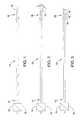
- FIG. 1shows catheter 10 , which includes an electromechanical polymer (EMP) actuator-embedded steerable tip 16 at distal end 18 , according to one embodiment of the present invention.
- EMPelectromechanical polymer
- FIG. 2shows catheter 10 of FIG. 1 , with the EMP actuator activated to deflect steerable tip 16 through an acute angle.
- FIG. 3shows catheter 10 of FIG. 1 , with the EMP actuator activated to deflect steerable tip 16 through an obtuse angle.
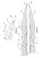
- FIG. 4shows steerable tip 16 at distal end 18 of catheter 10 , according to one embodiment of the present invention.
- FIG. 5is a cross section of steerable tip 16 of FIG. 4 , taken along line 5 - 5 .
- FIG. 6shows steerable tip 16 at distal end 18 of catheter 10 , according to a second embodiment of the present invention.
- FIG. 7is a cross section of steerable tip 16 of FIG. 6 , taken along line 7 - 7 .
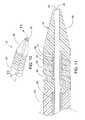
- FIG. 8shows steerable tip 16 at distal end 18 of the catheter 10 , according to a third embodiment of the present invention.
- FIG. 9is a cross section of steerable tip 16 of FIG. 8 , taken along line 9 - 9 .
- FIG. 10shows steerable tip 16 at distal end 18 of catheter 10 , having a helical EMP actuator, according to a fourth embodiment of the present invention.
- FIG. 11is a cross section of steerable tip 16 of FIG. 10 , taken along line 11 - 11 .
- FIG. 12shows steerable tip 16 at distal end 18 of catheter 10 , according to a fifth embodiment of the present invention.
- FIG. 13is a cross section of steerable tip 16 of FIG. 12 , taken along line 13 - 13 .
- FIG. 14shows EMP actuator 12 disposed in steerable tip 16 , according to a sixth embodiment of the present invention.
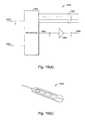
- FIG. 15shows EMP actuator 64 disposed in an intermediate section of body 22 of a catheter, in accordance with a seventh embodiment of the present invention.
- FIGS. 16A, 16B, 16C and 16Dare cross sections of the catheter of FIG. 15 , taken along lines 16 A- 16 A, 16 B- 16 B, 16 C- 16 C and 16 D- 16 D, respectively.
- FIG. 17shows EMP actuators disposed in body 22 of a catheter, in accordance with an eighth embodiment of the present invention.
- FIG. 18is a cross section showing EMP actuators of FIG. 17 , taken along line 18 - 18 .
- FIG. 19( a )shows schematic circuit 1900 in one implementation of controller 15 , according to another embodiment of the present invention.
- FIG. 19( b )shows user interface device 1950 having four selectable settings each corresponding to a pre-calibrated configuration of the catheter, in accordance with one embodiment of the present invention.
- FIG. 20shows schematic circuit 2000 in one implementation of controller 15 , according to one embodiment of the present invention.
- FIGS. 21( a ) and 21( b )show catheters 2101 and 2102 required to access the left and right coronary arteries, respectively.
- FIG. 1shows catheter 10 having steerable tip 16 at distal end 18 .
- Electromechanical polymer (EMP) actuator 12(not shown in FIG. 1 ; see, e.g., FIGS. 5, 7, 9, 11, 13 and 14 herein) is provided inside steerable tip 16 .
- EMP actuator 12may include one or more polymer layers with electromechanical properties.
- Copending U.S. patent application(“EMP Actuator Application”), Ser. No. 13/683,963, entitled “Localized Multimodal Electromechanical Transducers,” filed on Nov. 21, 2012, provides some examples of EMP actuators suitable for use in the present invention. The disclosure of the EMP Actuator application is hereby incorporated by reference in its entirety to provide technical background information.
- Electrical source 14 and controller 15 located at the proximal region 17may provide an electrical activation signal to activate EMP actuator 12 .
- the activation signalcauses, in this embodiment, a mechanical response from EMP actuator 12 in the form of a deformation (e.g., bending, stretching, contracting, rotating or vibrating).
- a modulated sequence of electrical pulses in the activation signalvaries the amount of deformation in EMP actuator 12 .
- Catheter 10includes lumen 20 for accommodating a guide wire.
- FIG. 1shows EMP actuator 12 to be located at or near distal region 18 of catheter 10 , EMP actuators 12 may also be disposed at other locations on catheter 10 to provide desired movements and articulations.
- EMP actuator 12may be modeled as a capacitor.
- EMP actuator 12includes an activated state, a charged inactive state, and a deactivated state. In the deactivated state, the terminals of the capacitor are grounded, so that EMP actuator 12 is not deformed or deflected.
- EMP actuator 12In the activated state, in response to an electrical current or a voltage applied to the electrodes of EMP actuator 12 , EMP actuator 12 undergoes a volumetric change that causes the actuator to bend, deflect, or vibrate.
- FIGS. 1-3illustrate deflecting steerable tip 16 from 0 degrees ( FIG. 1 ) through an acute angle ( FIG. 2 ) and an obtuse angle ( FIG. 3 ). If EMP actuator 12 is disconnected or is isolated from the power source while in the activated state, EMP actuator 12 enters the charged inactive state in which EMP actuator 12 maintains the bending or deflection indefinitely. In this state, catheter 10 is fixed in the desired shape until the power source is reconnected and EMP actuator 12 enters the deactivated or activated state under active control.
- FIGS. 21( a ) and 21( b )show catheters 2101 and 2102 required to access the left and right coronary arteries, respectively.
- catheters 2101 and 2102are of different shapes because the different locations of the access points into the left and right coronary arteries.
- the catheteris retracted, while leaving the guide wire in place, so that a different catheter can then be substituted. It is often the case in the prior art that a number of catheters are used in order to reach the location where therapy is required.
- steerable tip 16 of catheter 10electrically into different shapes, deflections or orientations as required provides a versatile catheter that helps to reduce or eliminate the need for changing catheters multiple times.
- multiple EMP actuatorspositioned at predetermined locations in steerable tip 16 of catheter 10 .
- FIG. 19( a )shows schematic circuit 1900 in one implementation of controller 15 , according to another embodiment of the present invention.
- circuit 1900receives selection signals 1903 and analog input signal 1904 at interface 1901 .
- An external host computermay provide these signals.
- Selection signals 1903 in circuit 1900is suitable for use in a catheter that has four EMI′ actuators.
- selection signals 1903may be a 2-bit bus that allows selection of any of the four EMP actuators.
- Interface 1901decodes selection signals 1903 to provide enable signals 1907 , which are each an enable signal to a corresponding one of the EMP actuators.
- Amplifier 1902amplifies analog signals 1905 , which are derived from analog input signal 1904 , to provide analog signals 1906 at the appropriate operating voltages for use with the EMP actuators (e.g., 0-1500 volts).
- Circuit 1900may also include power circuits (not shown) that provide the required supply voltages to amplifier 1902 .
- each of enable signals 1907may control a switch that conducts one of analog signals 1906 to the corresponding input terminals of the selected EMP actuator.
- a potentiometer(not shown) may allow manual fine adjustment of analog signal 1904 . Such a fine adjustment further refines the desired shape or position of the steerable tip. As each EMP actuator is electrically a capacitor, the EMP actuator remains activated so long as the electrodes remain charged.
- the external host computermay select the EMP actuators one by one to provide the corresponding required voltages. Relaxation of each EMP actuator is achieved by discharging (e.g., applying a zero voltage) to an activated EMP actuator.
- Analog signal 1904may include an AC component to enable vibrations.
- analog signal 1904may be an analog signal having an AC component modulated on a DC bias voltage. The DC bias voltage determines the deflection and the AC component provides the amplitude and frequency of vibration (e.g., 150-250 Hz).
- Available parameters to be set on analog signal 1904include frequency, amplitude, and pulsing parameters. Predetermined sets or parameters may be provided for user selection based on the desired force to be applied.
- the host computerstores a number of pre-determined configurations each representing a particular combination of control voltages for the EMP actuators in the catheter.
- the host computermay provide a user interface for a user to select a particular combination to apply to the catheter over interface 1901 to achieve any of the pre-defined shapes, deflections or orientations.
- FIG. 19( b )shows user interface 1950 having 4 selectable settings each corresponding to a pre-calibrated configuration of the catheter, in accordance with one embodiment of the present invention. As shown in FIG.
- a physiciancan select any of configurations “JR 4.0”, “JL 4.0”, “JR 3.5” and “JL 3.5.” These configurations correspond to names of catheters well known to those of ordinary skill in the art. The names encode the shape (J), orientation (L or R) and the reach (3.5 or 4.0 cm) of the catheter. In this manner, an operator may easily select any of a number of pre-calibrated desired shapes, deflections or orientations as required by simply pressing a button, as the catheter is steered along the guide wire to the desired location in the vasculature. Accordingly, the numerous shapes, deflections or orientations required to steer the catheter to its final location are achieved without changing catheters. As a result, a safer and shorter procedure is achieved.
- FIG. 20shows schematic circuit 2000 in one implementation of controller 15 , according to another embodiment of the present invention.
- controller 15includes interface 2002 , which receives control signals from an external host computer over an industry standard bus 2001 (e.g., a USB connection).
- the control signals on bus 2001may configure or program controller 15 .
- the control signals on bus 2001may be, for example, commands to controller 15 to output specific control signals to a specified EMP actuator.
- controller 15includes control logic circuit 2003 (e.g., a microprocessor), which may store into memory system 2004 configuration information that enables specific calibrated voltages to be applied to the EMP actuators to achieve specific pre-determined amounts of deflection or bending in that EMP actuator.
- Memory system 2004may include a non-volatile portion for storing calibrated configuration information. Such calibrated configuration information may be programmed into the non-volatile portion of the memory during a manufacturing step, before catheter 10 is put to clinical use. Alternatively, a physician may store particular configurations that he or she finds particularly useful or used often.
- controller 15may retrieve from memory system 2004 and may output the retrieved programmed voltage through output circuit 2005 on output bus 2006 .
- the retrieved program voltageis encoded in a digital signal.
- a digital-to-analog converter circuitconverts the digital signal to an analog voltage, which is then amplified in output circuit 2005 .
- Output bus 2006includes selection signals that specify the EMP actuator selected for activation, and the analog output signals that are applied to the EMP actuator to obtain a desired deflection angle, or any other suitable electromechanical response. By storing calibrated voltages, different predetermined electromechanical responses may be elicited from the EMP actuator, as needed.
- a catheter having a steerable tip of the present inventionpermits an operator to traverse the vascular system using a single catheter, or at least a very small number of catheters, without using frequent catheter changes, as required in certain applications.
- an EMP actuatorcan also act as a sensor. This is because a mechanical force imposed across the charged EMP actuator results in an electrical response.
- an EMP actuatore.g., in its charged inactive state
- These sensorsmay relay sensing signals representative of the conditions at the distal end of the catheter back to a processor (e.g., controller 15 ) for processing.
- a catheter integrating both EMP actuators and EMP actuators acting as sensorsthus includes an automatic closed-loop, dynamic compensation mechanism to maintain a desired combination of deflection and pressure.
- FIGS. 4 and 5illustrate catheter 10 , according to a first embodiment of the invention.
- Catheter 10has steerable catheter tip 16 , intermediate portion 22 , and lumen 20 that extends through the axial length of catheter 10 .
- Lumen 20is surrounded by thin liner 24 , which may be, for example, a one-mil thick PTFE material.
- Intermediate portion 22includes braided segment 26 which reinforces liner 24 , providing rigidity and support for lumen 20 , thus preventing lumen 20 from collapsing.
- the length of intermediate portion 22depends upon the type and application of catheter 10 , but may be up to about 100 cm long.
- Intermediate portion 22 and steerable tip 16may be formed integral to each other. Alternatively, steerable tip 16 and intermediate portion 22 may be separately formed and are attached to each other subsequently. As shown in FIG. 4 , EMP actuator 12 is embedded in one portion of steerable tip 16 and does not extend fully circumferentially around lumen 20 . Thus, EMP actuator 12 is seen only in an “upper” portion of FIG. 5 . In the activated state, the portion containing EMP actuator 12 bends toward the non-EMP actuator-containing portion of steerable tip 16 .
- EMP actuator 12By controlling the durometer and shape of the materials forming steerable tip 16 , the amount of deflection and orientation therein may be varied. As shown in FIG. 5 , the portion containing EMP actuator 12 in steerable tip 16 is relatively stiffer than the rest of the steerable tip 16 . As EMP actuator 12 is a thin, relatively fragile device (e.g., typically about 0.015 inches thick), EMP actuator 12 may be encapsulated in a relatively stiff urethane, for example. A suitable urethane may have, for example, a durometer of about 75 A for support and protection of EMP actuator 12 . As shown in FIG. 5 , EMP actuator 12 may be embedded in a relatively soft or flexible material 28 to provide strain relief. Strain relief material 28 may be, for example, a urethane having a durometer of about 25 A.
- EMP actuator 12 and strain relief material 28are encapsulated in a relatively soft and flexible material 30 , such as a urethane having a durometer of about 5 A.
- Material 30includes a radio-plaque filler (e.g., barium sulfate) to allow tracking by X-ray radiation of the location of steerable tip 16 , as catheter 10 is being threaded through the body's vasculature.
- a radio-plaque fillere.g., barium sulfate
- section 32which is formed out of a relatively stiff material to provide rigidity and strength to steerable tip 16 , is disposed at the periphery of steerable tip 16 where steerable tip 16 joins intermediate region 22 .
- the relatively stiff material of section 32may be, for example, a urethane material having a durometer of 75 A Shore.
- steerable tip 16permits an operator finer, safer and more accurate articulation of steerable tip 16 than are available in conventional catheters using guide wires by controlling the voltage applied to EMP actuator 12 in the activated state and selecting the durometer and shape of the material that surrounds EMP actuator 12 and steerable tip 16 .
- steerable tip 16may have a durometer of 5 A Shore to allow a deflection angle ( ⁇ ) of 180 degrees or more.
- ⁇deflection angle
- the deflection angle ( ⁇ )is limited to about 10 degrees.
- the operatormay make fine adjustments of the deflection angle and the orientation of steerable tip 16 and other portions of catheter 10 . Accordingly, the operator may aim steerable tip 16 with a high degree of precision through tortuous paths of the vasculature system.
- FIGS. 6 and 7illustrate catheter 10 , according to a second embodiment of the invention.
- distal portion 18 of catheter 10includes steerable tip 16 .
- relatively thin and fragile EMP actuator 12is disposed around lumen 20 in relatively flexible strain-relief material 28 .
- Steerable tip 16includes a relatively flexible and soft material in region 30 and a relatively stiff material in region 32 that surrounds EMP actuator 12 .
- region 32occupies an “upper” portion of steerable tip 16 .
- Region 32may be made out of a urethane material having a durometer of 75 A Shore.
- a suitable material for region 30may be, for example, a urethane having a durometer of 5 A Shore.
- EMP actuator 12When activated (i.e., a voltage being applied) EMP actuator 12 bends towards the more flexible and soft material of region 30 (i.e., “downwards” in FIG. 7 ), as EMP actuator 12 is embedded in the relatively stiff region 32 .
- FIGS. 8 and 9illustrate catheter 10 , in accordance with a third embodiment of the present invention.
- catheter 10includes EMP actuator 12 disposed in relatively flexible strain-relief section 28 adjacent lumen 20 .
- Steerable tip 16includes relatively stiff longitudinal strips 36 disposed on one side of the lumen 20 (i.e., the “upper” portion in FIG. 9 ).
- Relatively flexible region 38forms the rest of steerable tip 16 .
- EMP actuator 12When EMP actuator 12 is activated, the widths and the number of strips 36 control both the amount of deflection and the direction of deflection, bending steerable tip 16 towards relatively flexible region 38 .
- FIGS. 10 and 11illustrate catheter 10 , in accordance with a fourth embodiment of the invention.
- catheter 10includes EMP actuator 12 disposed in relatively flexible strain-relief section 28 adjacent lumen 20 .
- steerable tip 16includes relatively stiff region 40 in a helical or spiral strip disposed around the periphery of steerable tip 16 .
- Relatively stiff helical strip 40creates a flexible bending section that is also kink-resistant and torque-providing.
- Relatively flexible material in portion 42forms the remainder of steerable tip 16 .
- EMP actuator 12bends in response to an applied voltage.
- steerable tip 16may have two or more helical strips to achieve the desired articulations.
- FIGS. 12 and 13illustrate catheter 10 , in accordance with a fifth embodiment of the present invention.
- catheter 10includes EMP actuator 12 disposed in relatively flexible strain-relief section 28 adjacent lumen 20 .
- Relatively rigid portion 50 of steerable tip 16includes main body 51 and strips 52 extending outwardly from main body 51 .
- FIG. 13shows rigid portion 50 to include four strips 52 extending in a “downward” manner. When activated, EMP actuator 12 bends steerable tip 16 towards strips 52 (i.e. “downward” in FIG. 13 ).
- FIGS. 15 and 16disclose catheter 10 , in accordance with a seventh embodiment of the present invention.
- EMP actuator 64is disposed in catheter body 22 .
- Steering control of catheter body 22may be achieved by varying the length and the shape of EMP actuator 64 .
- EMP actuator 64may be provided in the form of a helical or curved strip.
- catheter body 22When inactive, catheter body 22 is relatively straight.
- catheter body 22bends in a direction controlled by the shape of EMP actuator 64 .
- Precise control of bending directions and deflection angles of catheter body 22can be achieved by varying the voltage applied, the length and the size of EMP actuators 64 , and its precise placement along catheter body 22 .
- EMP actuator 12 of steerable tip 16 in FIG. 14is embedded in a relatively rigid region and is spaced from lumen 20 .
- Relative soft and flexible region 30form the rest of steerable tip 16 .
- EMP actuator 12bends steerable tip 16 towards strips 30 (i.e. “downward” in FIG. 14 ).
- catheter 10includes EMP actuators 60 and 62 disposed in the body (i.e., intermediate region 22 ) of catheter 10 .
- EMP actuators 60 and 62are adjacent to each other, but offset at a predetermined angle relative to each other.
- an operatormay actuate either one or both of EMP actuators 60 and 62 to control the bending and orientation of catheter body 22 .
- catheter body 22is relatively straight.
- EMP actuator 60When only EMP actuator 60 is activated, catheter body 22 bends in a direction indicated generally by arrow A of FIG. 18 .
- EMP actuator 62When only EMP actuator 62 is activated, catheter body 22 bends in a direction indicated generally by arrow B of FIG. 18 .
- catheter 10bends in a direction indicated generally by arrow C of FIG. 18 .
- Precise control of bending directions and deflection angles of catheter body 22may be achieved by varying the sizes of EMP actuators 60 and 62 , the relative angle between EMP actuators 60 and 62 , and the material of catheter body 22 .
- a cathetermay have, in some instances, more than one lumen or may not have a continuous lumen at all. If a catheter has no lumen, the catheter may be used for such functionality as tissue ablation. If the catheter is shrunk or scaled down to the size of a guide wire, the catheter itself is its own guide wire, and there is no need to provide the lumen.
- the catheters of the present inventionmay be customized for such applications as tissue ablation, electrical mapping, stent delivery, embolics delivery, or guide wire steering. Catheters of the present invention may be equipped to perform these functions in the same manner as conventional catheters. In some applications, e.g., mechanical tissue removal, the EMP actuators may be stimulated using control signals with an AC component (e.g., 150-250 Hz).
Landscapes
- Health & Medical Sciences (AREA)
- Life Sciences & Earth Sciences (AREA)
- Biophysics (AREA)
- Pulmonology (AREA)
- Engineering & Computer Science (AREA)
- Anesthesiology (AREA)
- Biomedical Technology (AREA)
- Heart & Thoracic Surgery (AREA)
- Hematology (AREA)
- Animal Behavior & Ethology (AREA)
- General Health & Medical Sciences (AREA)
- Public Health (AREA)
- Veterinary Medicine (AREA)
- Media Introduction/Drainage Providing Device (AREA)
Abstract
Description
Claims (21)
Priority Applications (3)
| Application Number | Priority Date | Filing Date | Title |
|---|---|---|---|
| US14/015,841US9833596B2 (en) | 2013-08-30 | 2013-08-30 | Catheter having a steerable tip |
| PCT/US2014/053494WO2015031804A1 (en) | 2013-08-30 | 2014-08-29 | Catheter having a steerable tip |
| US15/832,617US10709871B2 (en) | 2013-08-30 | 2017-12-05 | Catheter having a steerable tip |
Applications Claiming Priority (1)
| Application Number | Priority Date | Filing Date | Title |
|---|---|---|---|
| US14/015,841US9833596B2 (en) | 2013-08-30 | 2013-08-30 | Catheter having a steerable tip |
Related Child Applications (1)
| Application Number | Title | Priority Date | Filing Date |
|---|---|---|---|
| US15/832,617DivisionUS10709871B2 (en) | 2013-08-30 | 2017-12-05 | Catheter having a steerable tip |
Publications (2)
| Publication Number | Publication Date |
|---|---|
| US20150065953A1 US20150065953A1 (en) | 2015-03-05 |
| US9833596B2true US9833596B2 (en) | 2017-12-05 |
Family
ID=52584224
Family Applications (2)
| Application Number | Title | Priority Date | Filing Date |
|---|---|---|---|
| US14/015,841Active2034-04-29US9833596B2 (en) | 2013-08-30 | 2013-08-30 | Catheter having a steerable tip |
| US15/832,617ActiveUS10709871B2 (en) | 2013-08-30 | 2017-12-05 | Catheter having a steerable tip |
Family Applications After (1)
| Application Number | Title | Priority Date | Filing Date |
|---|---|---|---|
| US15/832,617ActiveUS10709871B2 (en) | 2013-08-30 | 2017-12-05 | Catheter having a steerable tip |
Country Status (2)
| Country | Link |
|---|---|
| US (2) | US9833596B2 (en) |
| WO (1) | WO2015031804A1 (en) |
Cited By (1)
| Publication number | Priority date | Publication date | Assignee | Title |
|---|---|---|---|---|
| US20210162179A1 (en)* | 2018-04-12 | 2021-06-03 | Basecamp Vascular | Elongated functional system configured to be advanced in the lumen of a pipe, a duct or a tube |
Families Citing this family (7)
| Publication number | Priority date | Publication date | Assignee | Title |
|---|---|---|---|---|
| US9370640B2 (en) | 2007-09-12 | 2016-06-21 | Novasentis, Inc. | Steerable medical guide wire device |
| JP6234332B2 (en)* | 2014-06-25 | 2017-11-22 | オリンパス株式会社 | Endoscope apparatus, operation method, and operation program |
| JP6557414B2 (en) | 2015-10-27 | 2019-08-07 | コーニンクレッカ フィリップス エヌ ヴェKoninklijke Philips N.V. | Medical probe for ultrasound imaging |
| EP3420894A1 (en)* | 2017-06-28 | 2019-01-02 | Koninklijke Philips N.V. | Invasive medical device |
| US11969565B2 (en) | 2018-02-09 | 2024-04-30 | Baylor University | Programmable medical wire system and method |
| WO2021225535A1 (en)* | 2020-05-07 | 2021-11-11 | Ozyegin Universitesi | A guiding assembly for catheters. |
| US20220125454A1 (en) | 2020-10-23 | 2022-04-28 | Vicora, Inc. | Actuated thrombectomy device |
Citations (104)
| Publication number | Priority date | Publication date | Assignee | Title |
|---|---|---|---|---|
| US4863442A (en)* | 1987-08-14 | 1989-09-05 | C. R. Bard, Inc. | Soft tip catheter |
| US5234416A (en)* | 1991-06-06 | 1993-08-10 | Advanced Cardiovascular Systems, Inc. | Intravascular catheter with a nontraumatic distal tip |
| US5254107A (en)* | 1991-03-06 | 1993-10-19 | Cordis Corporation | Catheter having extended braid reinforced transitional tip |
| US5263876A (en) | 1992-09-15 | 1993-11-23 | Amphenol Corporation | Modular EMI-EMP connector assembly |
| US5350966A (en) | 1991-11-12 | 1994-09-27 | Rockwell International Corporation | Piezocellular propulsion |
| US5519278A (en) | 1994-12-23 | 1996-05-21 | The United States Of America As Represented By The Secretary Of The Navy | Actuators with graded activity |
| US5531685A (en)* | 1993-06-11 | 1996-07-02 | Catheter Research, Inc. | Steerable variable stiffness device |
| US5588964A (en) | 1992-12-01 | 1996-12-31 | Cardiac Pathways Corporation | Steerable catheter with adjustable bend location and/or radius and method |
| US6007478A (en)* | 1997-11-13 | 1999-12-28 | Impella Cardiotechnik Aktiengesellschaft | Cannula having constant wall thickness with increasing distal flexibility and method of making |
| US6071234A (en) | 1998-06-03 | 2000-06-06 | Takada; Masazumi | Self-propelled colonoscope |
| US6144547A (en) | 1997-11-24 | 2000-11-07 | Avx Corporation | Miniature surface mount capacitor and method of making same |
| US6160084A (en) | 1998-02-23 | 2000-12-12 | Massachusetts Institute Of Technology | Biodegradable shape memory polymers |
| US6183435B1 (en) | 1999-03-22 | 2001-02-06 | Cordis Webster, Inc. | Multi-directional steerable catheters and control handles |
| US6278084B1 (en) | 1996-09-05 | 2001-08-21 | Medtronic, Inc. | Method of making a distributed activator for a two-dimensional shape memory alloy |
| US20010051769A1 (en) | 2000-03-21 | 2001-12-13 | Bertil Hoek | Method and a device for measuring physical variables in a living body |
| US6376971B1 (en) | 1997-02-07 | 2002-04-23 | Sri International | Electroactive polymer electrodes |
| US6385472B1 (en) | 1999-09-10 | 2002-05-07 | Stereotaxis, Inc. | Magnetically navigable telescoping catheter and method of navigating telescoping catheter |
| US6423412B1 (en) | 1997-11-18 | 2002-07-23 | The Penn State Research Foundation | Ferroelectric relaxer polymers |
| US6514237B1 (en) | 2000-11-06 | 2003-02-04 | Cordis Corporation | Controllable intralumen medical device |
| US20030065373A1 (en) | 2001-10-02 | 2003-04-03 | Lovett Eric G. | Medical device having rheometric materials and method therefor |
| US20030236445A1 (en)* | 2002-06-21 | 2003-12-25 | Couvillon Lucien Alfred | Universal programmable guide catheter |
| US6703257B2 (en) | 2000-04-19 | 2004-03-09 | Ngk Insulators, Ltd. | Piezoelectric/electrostrictive film type elements and process for producing the same |
| US20040138733A1 (en) | 2002-10-15 | 2004-07-15 | Scimed Life Systems, Inc. | Nano-actuated medical device |
| US6770081B1 (en) | 2000-01-07 | 2004-08-03 | Intuitive Surgical, Inc. | In vivo accessories for minimally invasive robotic surgery and methods |
| US6787238B2 (en) | 1998-11-18 | 2004-09-07 | The Penn State Research Foundation | Terpolymer systems for electromechanical and dielectric applications |
| US6809462B2 (en) | 2000-04-05 | 2004-10-26 | Sri International | Electroactive polymer sensors |
| US6812624B1 (en) | 1999-07-20 | 2004-11-02 | Sri International | Electroactive polymers |
| US6852416B2 (en) | 2001-03-30 | 2005-02-08 | The Penn State Research Foundation | High dielectric constant composites of metallophthalaocyanine oligomer and poly(vinylidene-trifluoroethylene) copolymer |
| US6877325B1 (en) | 2002-06-27 | 2005-04-12 | Ceramphysics, Inc. | Electrocaloric device and thermal transfer systems employing the same |
| US6888291B2 (en) | 2002-10-31 | 2005-05-03 | The Boeing Company | Electrical system for electrostrictive bimorph actuator |
| US6891317B2 (en) | 2001-05-22 | 2005-05-10 | Sri International | Rolled electroactive polymers |
| US6921360B2 (en) | 2002-05-10 | 2005-07-26 | Boston Scientific Scimed. Inc. | Electroactive polymer based artificial sphincters and artificial muscle patches |
| US6939338B2 (en) | 2002-04-19 | 2005-09-06 | Medtronic, Inc. | Methods and apparatus for imparting curves in elongated medical catheters |
| US6969395B2 (en) | 2002-08-07 | 2005-11-29 | Boston Scientific Scimed, Inc. | Electroactive polymer actuated medical devices |
| US6979312B2 (en) | 2001-04-12 | 2005-12-27 | Biotran Corporation, Inc. | Steerable sheath catheters |
| US20060025809A1 (en) | 2004-07-28 | 2006-02-02 | Ethicon Endo-Surgery, Inc. | Surgical instrument incorporating an electrically actuated articulation mechanism |
| US20060047302A1 (en) | 2004-07-28 | 2006-03-02 | Ethicon Endo-Surgery, Inc. | Electroactive polymer-based articulation mechanism for grasper |
| US20060064055A1 (en)* | 2004-05-24 | 2006-03-23 | John Pile-Spellman | Steerable devices |
| US7038357B2 (en) | 2003-08-21 | 2006-05-02 | Engineering Services Inc. | Stretched rolled electroactive polymer transducers and method of producing same |
| US20060129130A1 (en) | 2004-11-18 | 2006-06-15 | Tal Michael G | Sheath/catheter system with controlled hardness and flexibility |
| US7078101B1 (en) | 2002-11-21 | 2006-07-18 | The United States Of America As Represented By The Secretary Of The Navy | High strain electrostrictive polymer |
| US7097615B2 (en) | 2001-10-05 | 2006-08-29 | Boston Scientific Scimed, Inc. | Robotic endoscope with wireless interface |
| KR20060107259A (en) | 2005-04-08 | 2006-10-13 | 한국생산기술연구원 | Polymer actuator and its control method for precise control of shrinkage displacement |
| US20060293643A1 (en) | 2004-03-05 | 2006-12-28 | Wallace Daniel T | Robotic catheter system |
| US20070032851A1 (en) | 2005-08-02 | 2007-02-08 | Boston Scientific Scimed, Inc. | Protection by electroactive polymer sleeve |
| US20070043338A1 (en) | 2004-03-05 | 2007-02-22 | Hansen Medical, Inc | Robotic catheter system and methods |
| US20070060997A1 (en) | 2005-09-15 | 2007-03-15 | Jan De Boer | Multi-lumen steerable catheter |
| US20070123750A1 (en) | 2005-11-30 | 2007-05-31 | General Electric Company | Catheter apparatus and methods of using same |
| US20070152974A1 (en) | 2006-01-03 | 2007-07-05 | Samsung Electronics Co., Ltd. | Haptic button and haptic device using the same |
| US20070200467A1 (en) | 1999-07-20 | 2007-08-30 | Sri International | Compliant electroactive polymer transducers for sonic applications |
| WO2007102939A1 (en) | 2006-03-06 | 2007-09-13 | Boston Scientific Limited | Adjustable catheter tip |
| WO2008016403A1 (en) | 2006-07-31 | 2008-02-07 | Boston Scientific Limited | Catheters having actuatable lumen assemblies |
| US7339572B2 (en) | 2000-05-24 | 2008-03-04 | Immersion Corporation | Haptic devices using electroactive polymers |
| US7368862B2 (en) | 1999-07-20 | 2008-05-06 | Sri International | Electroactive polymer generators |
| US20080284277A1 (en) | 2007-05-14 | 2008-11-20 | Samsung Electronics Co., Ltd. | Electroactive polymer actuator and manufacturing method thereof |
| US20090002328A1 (en) | 2007-06-26 | 2009-01-01 | Immersion Corporation, A Delaware Corporation | Method and apparatus for multi-touch tactile touch panel actuator mechanisms |
| US20090002205A1 (en) | 2007-06-28 | 2009-01-01 | Sony Ericsson Mobile Communications Ab | Data input device and portable electronic device |
| US7567681B2 (en) | 2003-09-03 | 2009-07-28 | Sri International | Surface deformation electroactive polymer transducers |
| US20100079264A1 (en) | 2008-09-29 | 2010-04-01 | Apple Inc. | Haptic feedback system |
| US20100090813A1 (en) | 2008-10-10 | 2010-04-15 | Richard Je | Electronic Device with Localized Haptic Response |
| WO2010085575A1 (en) | 2009-01-21 | 2010-07-29 | Artificial Muscle, Inc. | Electroactive polymer transducers for tactile feedback devices |
| US7766896B2 (en) | 2006-04-25 | 2010-08-03 | Boston Scientific Scimed, Inc. | Variable stiffness catheter assembly |
| US7839647B2 (en) | 2008-05-06 | 2010-11-23 | Foxconn Advanced Technology, Inc. | Insulating film, printed circuit board substrate and printed circuit board including same |
| US20100316242A1 (en) | 2007-11-21 | 2010-12-16 | Audio Pixels Ltd. | Digital speaker apparatus |
| JP2010283926A (en) | 2009-06-02 | 2010-12-16 | Kuraray Co Ltd | Polymer transducer |
| US20110038625A1 (en) | 2009-08-13 | 2011-02-17 | Strategic Polymer Sciences, Inc. | Electromechanical polymer actuators |
| US7944735B2 (en) | 2003-08-13 | 2011-05-17 | Nantero, Inc. | Method of making a nanotube-based shadow random access memory |
| US7952261B2 (en) | 2007-06-29 | 2011-05-31 | Bayer Materialscience Ag | Electroactive polymer transducers for sensory feedback applications |
| US20110133598A1 (en) | 2009-12-04 | 2011-06-09 | Bayer Materialscience Ag | Electromechanical transducer comprising a polyurethane polymer with polytetramethylene glycol ether units |
| US7971850B2 (en) | 1999-07-20 | 2011-07-05 | Sri International | Electroactive polymer devices for controlling fluid flow |
| JP2011172339A (en) | 2010-02-17 | 2011-09-01 | Seiko Epson Corp | Device for control of piezoelectric actuator, piezoelectric actuator device, and printing device |
| US20110290686A1 (en) | 2010-05-28 | 2011-12-01 | Yao-Hung Huang | Electronic device case |
| US20120017703A1 (en) | 2010-07-26 | 2012-01-26 | Seiko Epson Corporation | Detection device, electronic device, and robot |
| KR20120013273A (en) | 2011-12-22 | 2012-02-14 | 삼성전기주식회사 | Piezoelectric Actuator for Driving Haptic Devices |
| US8126534B2 (en) | 2005-06-16 | 2012-02-28 | Siemens Aktiengesellschaft | Medical catheter and system for inserting a catheter into a vessel |
| US20120105333A1 (en) | 2010-11-02 | 2012-05-03 | Apple Inc. | Methods and systems for providing haptic control |
| US20120121944A1 (en) | 2010-11-12 | 2012-05-17 | Takeru Yamamoto | Battery pack, method of manufacturing battery pack, and mold for manufacturing battery pack |
| US20120128960A1 (en) | 2009-04-11 | 2012-05-24 | Bayer Materialscience Ag | Electro-switchable polymer film assembly and use thereof |
| US20120126959A1 (en) | 2008-11-04 | 2012-05-24 | Bayer Materialscience Ag | Electroactive polymer transducers for tactile feedback devices |
| US20120126663A1 (en) | 2009-08-07 | 2012-05-24 | Bayer Materialscience Ag | Method for producing an electromechanical converter |
| KR20120063318A (en) | 2010-12-07 | 2012-06-15 | 삼성전자주식회사 | Multilayered electro-active polymer device and method for fabricating the same |
| KR20120078529A (en) | 2010-12-30 | 2012-07-10 | 삼성전기주식회사 | Piezoelectric actuator |
| JP2012134998A (en) | 2000-01-07 | 2012-07-12 | Emo Labs Inc | Mechanical-to-acoustical converter and multimedia flat film speaker |
| US20120178880A1 (en) | 2009-07-15 | 2012-07-12 | Qiming Zhang | Polymer blends electrostrictive terpolymer with other polymers |
| US8222799B2 (en) | 2008-11-05 | 2012-07-17 | Bayer Materialscience Ag | Surface deformation electroactive polymer transducers |
| US20120194448A1 (en) | 2011-01-31 | 2012-08-02 | Apple Inc. | Cover attachment with flexible display |
| US20120206248A1 (en) | 2009-10-19 | 2012-08-16 | Biggs Silmon James | Flexure assemblies and fixtures for haptic feedback |
| US20120223880A1 (en) | 2012-02-15 | 2012-09-06 | Immersion Corporation | Method and apparatus for producing a dynamic haptic effect |
| US20120239032A1 (en) | 2007-07-20 | 2012-09-20 | Strategic Polymer Sciences, Inc. | Micro-steerable catheter |
| KR20120105785A (en) | 2011-03-16 | 2012-09-26 | 삼성테크윈 주식회사 | Piezoelectric device |
| US8362882B2 (en) | 2008-12-10 | 2013-01-29 | Immersion Corporation | Method and apparatus for providing Haptic feedback from Haptic textile |
| US8384271B2 (en) | 2009-11-16 | 2013-02-26 | Samsung Electronics Co., Ltd. | Electroactive polymer actuator and method of manufacturing the same |
| US8390594B2 (en) | 2009-08-18 | 2013-03-05 | Immersion Corporation | Haptic feedback using composite piezoelectric actuator |
| US8398693B2 (en) | 2004-01-23 | 2013-03-19 | Boston Scientific Scimed, Inc. | Electrically actuated medical devices |
| US8427441B2 (en) | 2008-12-23 | 2013-04-23 | Research In Motion Limited | Portable electronic device and method of control |
| US20130123692A1 (en) | 2007-09-12 | 2013-05-16 | Strategic Polymer Sciences, Inc. | Steerable Medical Guide Wire Device |
| US20140035735A1 (en) | 2012-08-03 | 2014-02-06 | Strategic Polymer Sciences, Inc. | Localized multimodal electromechanical polymer transducers |
| US20140085065A1 (en) | 2011-03-09 | 2014-03-27 | Bayer Intellectual Property Gmbh | Electroactive polymer actuator feedback apparatus system and method |
| US20140090424A1 (en) | 2010-06-17 | 2014-04-03 | Johns Manville | Methods and systems for destabilizing foam in equipment downstream of a submerged combustion melter |
| US20140140551A1 (en) | 2012-11-21 | 2014-05-22 | Strategic Polymer Sciences, Inc. | System of Audio Speakers Implemented Using EMP Actuators |
| US20140139328A1 (en) | 2012-11-21 | 2014-05-22 | Strategic Polymer Sciences, Inc. | Haptic system with localized response |
| US20140139436A1 (en) | 2012-11-21 | 2014-05-22 | Strategic Polymer Sciences, Inc. | EMP Actuators for Deformable Surface and Keyboard Application |
| US20140139329A1 (en) | 2012-11-21 | 2014-05-22 | Strategic Polymer Sciences, Inc. | Systems including electromechanical polymer sensors and actuators |
| US20140191973A1 (en) | 2013-01-07 | 2014-07-10 | Strategic Polymer Sciences, Inc. | Thin profile user interface device and method providing localized haptic response |
Family Cites Families (4)
| Publication number | Priority date | Publication date | Assignee | Title |
|---|---|---|---|---|
| DE69317857T2 (en)* | 1992-11-20 | 1998-08-06 | Topometrix | Linearization and calibration system for a scanning device |
| US5681336A (en)* | 1995-09-07 | 1997-10-28 | Boston Scientific Corporation | Therapeutic device for treating vien graft lesions |
| US7233097B2 (en)* | 2001-05-22 | 2007-06-19 | Sri International | Rolled electroactive polymers |
| EP1970001B1 (en)* | 2007-03-16 | 2014-07-23 | Brainlab AG | Catheter with pressure sensoring |
- 2013
- 2013-08-30USUS14/015,841patent/US9833596B2/enactiveActive
- 2014
- 2014-08-29WOPCT/US2014/053494patent/WO2015031804A1/enactiveApplication Filing
- 2017
- 2017-12-05USUS15/832,617patent/US10709871B2/enactiveActive
Patent Citations (115)
| Publication number | Priority date | Publication date | Assignee | Title |
|---|---|---|---|---|
| US4863442A (en)* | 1987-08-14 | 1989-09-05 | C. R. Bard, Inc. | Soft tip catheter |
| US5254107A (en)* | 1991-03-06 | 1993-10-19 | Cordis Corporation | Catheter having extended braid reinforced transitional tip |
| US5234416A (en)* | 1991-06-06 | 1993-08-10 | Advanced Cardiovascular Systems, Inc. | Intravascular catheter with a nontraumatic distal tip |
| US5350966A (en) | 1991-11-12 | 1994-09-27 | Rockwell International Corporation | Piezocellular propulsion |
| US5263876A (en) | 1992-09-15 | 1993-11-23 | Amphenol Corporation | Modular EMI-EMP connector assembly |
| US5588964A (en) | 1992-12-01 | 1996-12-31 | Cardiac Pathways Corporation | Steerable catheter with adjustable bend location and/or radius and method |
| US5531685A (en)* | 1993-06-11 | 1996-07-02 | Catheter Research, Inc. | Steerable variable stiffness device |
| US5519278A (en) | 1994-12-23 | 1996-05-21 | The United States Of America As Represented By The Secretary Of The Navy | Actuators with graded activity |
| US6278084B1 (en) | 1996-09-05 | 2001-08-21 | Medtronic, Inc. | Method of making a distributed activator for a two-dimensional shape memory alloy |
| US6376971B1 (en) | 1997-02-07 | 2002-04-23 | Sri International | Electroactive polymer electrodes |
| US6007478A (en)* | 1997-11-13 | 1999-12-28 | Impella Cardiotechnik Aktiengesellschaft | Cannula having constant wall thickness with increasing distal flexibility and method of making |
| US6605246B2 (en) | 1997-11-18 | 2003-08-12 | The Penn State Research Foundation | Ferroelectric relaxor polymer method |
| US6423412B1 (en) | 1997-11-18 | 2002-07-23 | The Penn State Research Foundation | Ferroelectric relaxer polymers |
| US6144547A (en) | 1997-11-24 | 2000-11-07 | Avx Corporation | Miniature surface mount capacitor and method of making same |
| US6160084A (en) | 1998-02-23 | 2000-12-12 | Massachusetts Institute Of Technology | Biodegradable shape memory polymers |
| US6071234A (en) | 1998-06-03 | 2000-06-06 | Takada; Masazumi | Self-propelled colonoscope |
| US6787238B2 (en) | 1998-11-18 | 2004-09-07 | The Penn State Research Foundation | Terpolymer systems for electromechanical and dielectric applications |
| US6183435B1 (en) | 1999-03-22 | 2001-02-06 | Cordis Webster, Inc. | Multi-directional steerable catheters and control handles |
| US6812624B1 (en) | 1999-07-20 | 2004-11-02 | Sri International | Electroactive polymers |
| US7368862B2 (en) | 1999-07-20 | 2008-05-06 | Sri International | Electroactive polymer generators |
| US20070200467A1 (en) | 1999-07-20 | 2007-08-30 | Sri International | Compliant electroactive polymer transducers for sonic applications |
| US7971850B2 (en) | 1999-07-20 | 2011-07-05 | Sri International | Electroactive polymer devices for controlling fluid flow |
| US7224106B2 (en) | 1999-07-20 | 2007-05-29 | Sri International | Electroactive polymers |
| US7199501B2 (en) | 1999-07-20 | 2007-04-03 | Sri International | Electroactive polymers |
| US6385472B1 (en) | 1999-09-10 | 2002-05-07 | Stereotaxis, Inc. | Magnetically navigable telescoping catheter and method of navigating telescoping catheter |
| JP2012134998A (en) | 2000-01-07 | 2012-07-12 | Emo Labs Inc | Mechanical-to-acoustical converter and multimedia flat film speaker |
| US6770081B1 (en) | 2000-01-07 | 2004-08-03 | Intuitive Surgical, Inc. | In vivo accessories for minimally invasive robotic surgery and methods |
| US20010051769A1 (en) | 2000-03-21 | 2001-12-13 | Bertil Hoek | Method and a device for measuring physical variables in a living body |
| US6809462B2 (en) | 2000-04-05 | 2004-10-26 | Sri International | Electroactive polymer sensors |
| US6703257B2 (en) | 2000-04-19 | 2004-03-09 | Ngk Insulators, Ltd. | Piezoelectric/electrostrictive film type elements and process for producing the same |
| US7339572B2 (en) | 2000-05-24 | 2008-03-04 | Immersion Corporation | Haptic devices using electroactive polymers |
| US6514237B1 (en) | 2000-11-06 | 2003-02-04 | Cordis Corporation | Controllable intralumen medical device |
| US6852416B2 (en) | 2001-03-30 | 2005-02-08 | The Penn State Research Foundation | High dielectric constant composites of metallophthalaocyanine oligomer and poly(vinylidene-trifluoroethylene) copolymer |
| US6979312B2 (en) | 2001-04-12 | 2005-12-27 | Biotran Corporation, Inc. | Steerable sheath catheters |
| US6891317B2 (en) | 2001-05-22 | 2005-05-10 | Sri International | Rolled electroactive polymers |
| US20030065373A1 (en) | 2001-10-02 | 2003-04-03 | Lovett Eric G. | Medical device having rheometric materials and method therefor |
| US7097615B2 (en) | 2001-10-05 | 2006-08-29 | Boston Scientific Scimed, Inc. | Robotic endoscope with wireless interface |
| US6939338B2 (en) | 2002-04-19 | 2005-09-06 | Medtronic, Inc. | Methods and apparatus for imparting curves in elongated medical catheters |
| US6921360B2 (en) | 2002-05-10 | 2005-07-26 | Boston Scientific Scimed. Inc. | Electroactive polymer based artificial sphincters and artificial muscle patches |
| US7128707B2 (en) | 2002-05-10 | 2006-10-31 | Boston Scientific Scimed, Inc. | Electroactive polymer based artificial sphincters and artificial muscle patches |
| US7261686B2 (en) | 2002-06-21 | 2007-08-28 | Boston Scientific Scimed, Inc. | Universal, programmable guide catheter |
| US6997870B2 (en) | 2002-06-21 | 2006-02-14 | Boston Scientific Scimed, Inc. | Universal, programmable guide catheter |
| US20030236445A1 (en)* | 2002-06-21 | 2003-12-25 | Couvillon Lucien Alfred | Universal programmable guide catheter |
| US6877325B1 (en) | 2002-06-27 | 2005-04-12 | Ceramphysics, Inc. | Electrocaloric device and thermal transfer systems employing the same |
| US6969395B2 (en) | 2002-08-07 | 2005-11-29 | Boston Scientific Scimed, Inc. | Electroactive polymer actuated medical devices |
| US20040138733A1 (en) | 2002-10-15 | 2004-07-15 | Scimed Life Systems, Inc. | Nano-actuated medical device |
| US6888291B2 (en) | 2002-10-31 | 2005-05-03 | The Boeing Company | Electrical system for electrostrictive bimorph actuator |
| US7078101B1 (en) | 2002-11-21 | 2006-07-18 | The United States Of America As Represented By The Secretary Of The Navy | High strain electrostrictive polymer |
| US7944735B2 (en) | 2003-08-13 | 2011-05-17 | Nantero, Inc. | Method of making a nanotube-based shadow random access memory |
| US7038357B2 (en) | 2003-08-21 | 2006-05-02 | Engineering Services Inc. | Stretched rolled electroactive polymer transducers and method of producing same |
| US7567681B2 (en) | 2003-09-03 | 2009-07-28 | Sri International | Surface deformation electroactive polymer transducers |
| US8398693B2 (en) | 2004-01-23 | 2013-03-19 | Boston Scientific Scimed, Inc. | Electrically actuated medical devices |
| US20070043338A1 (en) | 2004-03-05 | 2007-02-22 | Hansen Medical, Inc | Robotic catheter system and methods |
| US20060293643A1 (en) | 2004-03-05 | 2006-12-28 | Wallace Daniel T | Robotic catheter system |
| US20060064055A1 (en)* | 2004-05-24 | 2006-03-23 | John Pile-Spellman | Steerable devices |
| US20060025809A1 (en) | 2004-07-28 | 2006-02-02 | Ethicon Endo-Surgery, Inc. | Surgical instrument incorporating an electrically actuated articulation mechanism |
| US20060047302A1 (en) | 2004-07-28 | 2006-03-02 | Ethicon Endo-Surgery, Inc. | Electroactive polymer-based articulation mechanism for grasper |
| US20060129130A1 (en) | 2004-11-18 | 2006-06-15 | Tal Michael G | Sheath/catheter system with controlled hardness and flexibility |
| KR20060107259A (en) | 2005-04-08 | 2006-10-13 | 한국생산기술연구원 | Polymer actuator and its control method for precise control of shrinkage displacement |
| US8126534B2 (en) | 2005-06-16 | 2012-02-28 | Siemens Aktiengesellschaft | Medical catheter and system for inserting a catheter into a vessel |
| US20070032851A1 (en) | 2005-08-02 | 2007-02-08 | Boston Scientific Scimed, Inc. | Protection by electroactive polymer sleeve |
| US20070060997A1 (en) | 2005-09-15 | 2007-03-15 | Jan De Boer | Multi-lumen steerable catheter |
| US20070123750A1 (en) | 2005-11-30 | 2007-05-31 | General Electric Company | Catheter apparatus and methods of using same |
| US20070152974A1 (en) | 2006-01-03 | 2007-07-05 | Samsung Electronics Co., Ltd. | Haptic button and haptic device using the same |
| WO2007102939A1 (en) | 2006-03-06 | 2007-09-13 | Boston Scientific Limited | Adjustable catheter tip |
| US8414632B2 (en) | 2006-03-06 | 2013-04-09 | Boston Scientific Scimed, Inc. | Adjustable catheter tip |
| US7766896B2 (en) | 2006-04-25 | 2010-08-03 | Boston Scientific Scimed, Inc. | Variable stiffness catheter assembly |
| US7909844B2 (en) | 2006-07-31 | 2011-03-22 | Boston Scientific Scimed, Inc. | Catheters having actuatable lumen assemblies |
| WO2008016403A1 (en) | 2006-07-31 | 2008-02-07 | Boston Scientific Limited | Catheters having actuatable lumen assemblies |
| US20080284277A1 (en) | 2007-05-14 | 2008-11-20 | Samsung Electronics Co., Ltd. | Electroactive polymer actuator and manufacturing method thereof |
| US20090002328A1 (en) | 2007-06-26 | 2009-01-01 | Immersion Corporation, A Delaware Corporation | Method and apparatus for multi-touch tactile touch panel actuator mechanisms |
| US20090002205A1 (en) | 2007-06-28 | 2009-01-01 | Sony Ericsson Mobile Communications Ab | Data input device and portable electronic device |
| US7952261B2 (en) | 2007-06-29 | 2011-05-31 | Bayer Materialscience Ag | Electroactive polymer transducers for sensory feedback applications |
| US20120239032A1 (en) | 2007-07-20 | 2012-09-20 | Strategic Polymer Sciences, Inc. | Micro-steerable catheter |
| US20130123692A1 (en) | 2007-09-12 | 2013-05-16 | Strategic Polymer Sciences, Inc. | Steerable Medical Guide Wire Device |
| US20100316242A1 (en) | 2007-11-21 | 2010-12-16 | Audio Pixels Ltd. | Digital speaker apparatus |
| US7839647B2 (en) | 2008-05-06 | 2010-11-23 | Foxconn Advanced Technology, Inc. | Insulating film, printed circuit board substrate and printed circuit board including same |
| US20100079264A1 (en) | 2008-09-29 | 2010-04-01 | Apple Inc. | Haptic feedback system |
| US20100090813A1 (en) | 2008-10-10 | 2010-04-15 | Richard Je | Electronic Device with Localized Haptic Response |
| US20120126959A1 (en) | 2008-11-04 | 2012-05-24 | Bayer Materialscience Ag | Electroactive polymer transducers for tactile feedback devices |
| US8222799B2 (en) | 2008-11-05 | 2012-07-17 | Bayer Materialscience Ag | Surface deformation electroactive polymer transducers |
| US8362882B2 (en) | 2008-12-10 | 2013-01-29 | Immersion Corporation | Method and apparatus for providing Haptic feedback from Haptic textile |
| US8427441B2 (en) | 2008-12-23 | 2013-04-23 | Research In Motion Limited | Portable electronic device and method of control |
| KR20110110212A (en) | 2009-01-21 | 2011-10-06 | 바이엘 머티리얼사이언스 아게 | Electroactive Polymer Transducers for Tactile Feedback Devices |
| US20130207793A1 (en) | 2009-01-21 | 2013-08-15 | Bayer Materialscience Ag | Electroactive polymer transducers for tactile feedback devices |
| WO2010085575A1 (en) | 2009-01-21 | 2010-07-29 | Artificial Muscle, Inc. | Electroactive polymer transducers for tactile feedback devices |
| US20120128960A1 (en) | 2009-04-11 | 2012-05-24 | Bayer Materialscience Ag | Electro-switchable polymer film assembly and use thereof |
| JP2010283926A (en) | 2009-06-02 | 2010-12-16 | Kuraray Co Ltd | Polymer transducer |
| US20120178880A1 (en) | 2009-07-15 | 2012-07-12 | Qiming Zhang | Polymer blends electrostrictive terpolymer with other polymers |
| US20120126663A1 (en) | 2009-08-07 | 2012-05-24 | Bayer Materialscience Ag | Method for producing an electromechanical converter |
| US20110038625A1 (en) | 2009-08-13 | 2011-02-17 | Strategic Polymer Sciences, Inc. | Electromechanical polymer actuators |
| US8390594B2 (en) | 2009-08-18 | 2013-03-05 | Immersion Corporation | Haptic feedback using composite piezoelectric actuator |
| US20120206248A1 (en) | 2009-10-19 | 2012-08-16 | Biggs Silmon James | Flexure assemblies and fixtures for haptic feedback |
| US8384271B2 (en) | 2009-11-16 | 2013-02-26 | Samsung Electronics Co., Ltd. | Electroactive polymer actuator and method of manufacturing the same |
| US20110133598A1 (en) | 2009-12-04 | 2011-06-09 | Bayer Materialscience Ag | Electromechanical transducer comprising a polyurethane polymer with polytetramethylene glycol ether units |
| JP2011172339A (en) | 2010-02-17 | 2011-09-01 | Seiko Epson Corp | Device for control of piezoelectric actuator, piezoelectric actuator device, and printing device |
| US20110290686A1 (en) | 2010-05-28 | 2011-12-01 | Yao-Hung Huang | Electronic device case |
| US20140090424A1 (en) | 2010-06-17 | 2014-04-03 | Johns Manville | Methods and systems for destabilizing foam in equipment downstream of a submerged combustion melter |
| US20120017703A1 (en) | 2010-07-26 | 2012-01-26 | Seiko Epson Corporation | Detection device, electronic device, and robot |
| US20120105333A1 (en) | 2010-11-02 | 2012-05-03 | Apple Inc. | Methods and systems for providing haptic control |
| US20120121944A1 (en) | 2010-11-12 | 2012-05-17 | Takeru Yamamoto | Battery pack, method of manufacturing battery pack, and mold for manufacturing battery pack |
| US8564181B2 (en) | 2010-12-07 | 2013-10-22 | Samsung Electronics Co., Ltd. | Electroactive polymer actuator and method of manufacturing the same |
| KR20120063318A (en) | 2010-12-07 | 2012-06-15 | 삼성전자주식회사 | Multilayered electro-active polymer device and method for fabricating the same |
| KR20120078529A (en) | 2010-12-30 | 2012-07-10 | 삼성전기주식회사 | Piezoelectric actuator |
| US20120194448A1 (en) | 2011-01-31 | 2012-08-02 | Apple Inc. | Cover attachment with flexible display |
| US20140085065A1 (en) | 2011-03-09 | 2014-03-27 | Bayer Intellectual Property Gmbh | Electroactive polymer actuator feedback apparatus system and method |
| KR20120105785A (en) | 2011-03-16 | 2012-09-26 | 삼성테크윈 주식회사 | Piezoelectric device |
| KR20120013273A (en) | 2011-12-22 | 2012-02-14 | 삼성전기주식회사 | Piezoelectric Actuator for Driving Haptic Devices |
| US20120223880A1 (en) | 2012-02-15 | 2012-09-06 | Immersion Corporation | Method and apparatus for producing a dynamic haptic effect |
| US20140035735A1 (en) | 2012-08-03 | 2014-02-06 | Strategic Polymer Sciences, Inc. | Localized multimodal electromechanical polymer transducers |
| US20140140551A1 (en) | 2012-11-21 | 2014-05-22 | Strategic Polymer Sciences, Inc. | System of Audio Speakers Implemented Using EMP Actuators |
| US20140139328A1 (en) | 2012-11-21 | 2014-05-22 | Strategic Polymer Sciences, Inc. | Haptic system with localized response |
| US20140139436A1 (en) | 2012-11-21 | 2014-05-22 | Strategic Polymer Sciences, Inc. | EMP Actuators for Deformable Surface and Keyboard Application |
| US20140139329A1 (en) | 2012-11-21 | 2014-05-22 | Strategic Polymer Sciences, Inc. | Systems including electromechanical polymer sensors and actuators |
| US20140191973A1 (en) | 2013-01-07 | 2014-07-10 | Strategic Polymer Sciences, Inc. | Thin profile user interface device and method providing localized haptic response |
Non-Patent Citations (33)
| Title |
|---|
| Arai, F. et al., "Intelligent Assistance in Operation of Active Catheter for Minimum Invasive Surgery," paper for IEEE International Workshop on Robot and Human Communication, dated Jun. 1994, pp. 192-197. |
| Bar-Cohen, Y., Biomimetics: Biologically Inspired Technologies, textbook "Chapter 10, Artificial Muscles Using Electroactive Polymers", 2005, Jet Propulsion Laboratory (JPL), Pasadena, CA, pp. 267-290. |
| Brochu, P. et al., "Advances in Dielectric Elastomers for Actuators and Artificial Muscles," Macromolecular Journals, Macromolecular Rapid Communications, dated 2010, pp. 10-36. |
| Della Santa, A. et al., "Intravascular Microcatheters Steered by Conducting Polymer Actuators," paper for IEEE, dated Jan. 1997, pp. 2203-2204. |
| Fukuda, T. et al., "Micro Active Catheter System with Multi Degrees of Freedom," paper for IEEE, dated 1994, pp. 2290-2295. |
| Guo, S. et al., "Micro Active Catheter Using ICPF Actuator; Characteristic Evaluation, Electrical Model and Operability Evaluation," paper for IEEE, dated Jun. 1996, pp. 1312-1317. |
| Guo, S. et al., "Micro Active Guide Wire Catheter System," paper for IEEE, dated Apr. 1995, pp. 172-177. |
| Guo, S. et al., "Micro Active Guide Wire Catheter Using ICPF Actuator," paper for IEEE, dated Sep. 1996, pp. 729-734. |
| Guo, S. et al., "Micro Catheter System with Active Guide Wire," paper for IEEE International Conference on Robotics and Automation, dated Jun. 1995, pp. 79-84. |
| International Search Report and Written Opinion for PCT/US2014/053494, dated Dec. 18, 2014, 11 pgs. |
| Matysek, Marc et al., "Combined Driving and Sensing Circuitry for Dielectric Elastomer Actuators in mobile applications", Electroactive Polymer Actuators and Devices (EAPAD) 2011, Proc. of SPIE vol. 7976, 797612, 11 pages. |
| Mazzoldi, A. et al., "Conductive polymer based structures for a steerable catheter," in Smart Structures and Materials 2000: Electroactive Polymer Actuators and Devices (EAPAD), proceedings of SPIE vol. 3987 (2000), pp. 273-280. |
| Neese, Bret et al., "Large Electrocaloric Effect in Ferroelectric Polymers Near Room Temperature", Science vol. 321, Aug. 8, 2008, pp. 821-823. |
| PCT International Preliminary Report on Patentability dated Jul. 16, 2015, International Application No. PCT/IB2013/003212, 15 pages. |
| PCT International Preliminary Report on Patentability dated Jul. 16, 2015, International Application No. PCT/US2014/010219, 14 pages. |
| PCT International Preliminary Report on Patentability dated Jun. 4, 2015, International Application No. PCT/US2013/071072, 9 pages. |
| PCT International Preliminary Report on Patentability dated Jun. 4, 2015, International Application No. PCT/US2013/071075, 9 pages. |
| PCT International Preliminary Report on Patentability for PCT/US2014/053494, dated Mar. 10, 2016, 10 pages. |
| PCT International Preliminary Report on Patentability, dated Jun. 4, 2015, International Application No. PCT/US2013/071078, 10 pages. |
| PCT International Preliminary Report on Patentability, dated Jun. 4, 2015, International Application No. PCT/US2013/071085; 7 pages. |
| PCT International Search Report and Written Opinion dated Apr. 28, 2014, International Application No. PCT/US2013/071062, 11 pages. |
| PCT International Search Report and Written Opinion dated Dec. 23, 2013, International Application No. PCT/US2013/053594, 9 pages. |
| PCT International Search Report and Written Opinion dated Mar. 13, 2014, International Application No. PCT/US2013/071072, 15 pages. |
| PCT International Search Report and Written Opinion dated Mar. 17, 2014, International Application No. PCT/US2013/071085, 10 pages. |
| PCT International Search Report and Written Opinion dated Mar. 20, 2014, International Application No. PCT/US2013/071075, 12 pages. |
| PCT International Search Report and Written Opinion dated Mar. 28, 2014, International Application No. PCT/US2013/071078, 13 pages. |
| PCT International Search Report and Written Opinion, dated Dec. 18, 2014, International Application No. PCT/US2014/053494, 11 pages. |
| PCT International Search Report and Written Opinion, dated May 23, 2014, International Application No. PCT/US2014/010219, 21 pages. |
| PCT International Search Report and Written Opinion, dated Nov. 7, 2008, International Application No. PCT/US2008/070450, 10 pages. |
| PCT International Search Report and Written Opinion, dated Oct. 15, 2014, International Application No. PCT/IB2013/003212, 20 pages. |
| Spinks, G. M. et al., "Strain Response from Polypyrrole Actuators under Load," Advanced Functional Materials, dated Jun. 2002, pp. 437-440. |
| Xia F. et al., "High Electromechanical Responses in a Poly(vinylidene fluoride-trifluoroethylene-chlorofluoroethylene) Terpolymer", Advanced Materials, vol. 14, Issue 21, Nov. 2002, pp. 1574-1577. |
| Zhang Q. M. et al., "Giant Electrostriction and Relaxor Ferroelectric Behavior in Electron-Irradiated Poly(vinylidene fluoride-trifluoroethylene) Copolymer", Science vol. 280, Jun. 26, 1998, pp. 2101-2104. |
Cited By (1)
| Publication number | Priority date | Publication date | Assignee | Title |
|---|---|---|---|---|
| US20210162179A1 (en)* | 2018-04-12 | 2021-06-03 | Basecamp Vascular | Elongated functional system configured to be advanced in the lumen of a pipe, a duct or a tube |
Also Published As
| Publication number | Publication date |
|---|---|
| WO2015031804A1 (en) | 2015-03-05 |
| US20150065953A1 (en) | 2015-03-05 |
| US10709871B2 (en) | 2020-07-14 |
| US20180099121A1 (en) | 2018-04-12 |
Similar Documents
| Publication | Publication Date | Title |
|---|---|---|
| US10709871B2 (en) | Catheter having a steerable tip | |
| US20210308424A1 (en) | Balloon catheter with high articulation | |
| US20240285900A1 (en) | Sheath Visualization | |
| US9956378B2 (en) | Catheter assembly | |
| US11051877B2 (en) | Medical device with contact force sensing tip | |
| US6939338B2 (en) | Methods and apparatus for imparting curves in elongated medical catheters | |
| EP1515772B1 (en) | Universal programmable guide catheter | |
| US20180000540A1 (en) | An improved catheter and method of manufacture thereof | |
| EP3318211A2 (en) | Non-contact electrode basket catheters with irrigation | |
| CN106852124A (en) | For the delivery device and method of leadless cardiac equipment | |
| AU2019200908A1 (en) | Catheter with multifunctional microinjection-molded housing | |
| US20070123750A1 (en) | Catheter apparatus and methods of using same | |
| CN111374755B (en) | Medical device shaft with reduced agitation | |
| JP7349562B2 (en) | Catheter including a deflectable shaft and method of assembling the same | |
| EP3398502A1 (en) | Mechanical material characterization in a patient body | |
| CN116785555A (en) | Retractable vascular interventional surgical catheters, catheter systems and methods of use |
Legal Events
| Date | Code | Title | Description |
|---|---|---|---|
| AS | Assignment | Owner name:STRATEGIC POLYMER SCIENCES, INC., PENNSYLVANIA Free format text:ASSIGNMENT OF ASSIGNORS INTEREST;ASSIGNORS:DUCHARME, RICHARD;LEVATICH, MARK;RAMSTEIN, CHRISTOPHE;SIGNING DATES FROM 20131105 TO 20131112;REEL/FRAME:032762/0310 | |
| AS | Assignment | Owner name:NOVASENTIS, INC., CALIFORNIA Free format text:CHANGE OF NAME;ASSIGNOR:STRATEGIC POLYMER SCIENCES, INC.;REEL/FRAME:035207/0207 Effective date:20131018 | |
| STCF | Information on status: patent grant | Free format text:PATENTED CASE | |
| AS | Assignment | Owner name:STRATEGIC POLYMER SCIENCES, INC., PENNSYLVANIA Free format text:INVENTION ASSIGNMENT AGREEMENT;ASSIGNOR:DUCHARME, RICHARD;REEL/FRAME:050311/0561 Effective date:20120509 Owner name:STRATEGIC POLYMER SCIENCES, INC., PENNSYLVANIA Free format text:INVENTION ASSIGNMENT AGREEMENT;ASSIGNOR:LEVATICH, MARK;REEL/FRAME:050311/0436 Effective date:20121011 Owner name:STRATEGIC POLYMER SCIENCES, INC., PENNSYLVANIA Free format text:INVENTION ASSIGNMENT AGREEMENT;ASSIGNOR:RAMSTEIN, CHRISTOPHE;REEL/FRAME:050311/0553 Effective date:20121112 | |
| FEPP | Fee payment procedure | Free format text:ENTITY STATUS SET TO UNDISCOUNTED (ORIGINAL EVENT CODE: BIG.); ENTITY STATUS OF PATENT OWNER: LARGE ENTITY | |
| MAFP | Maintenance fee payment | Free format text:PAYMENT OF MAINTENANCE FEE, 4TH YEAR, LARGE ENTITY (ORIGINAL EVENT CODE: M1551); ENTITY STATUS OF PATENT OWNER: LARGE ENTITY Year of fee payment:4 | |
| AS | Assignment | Owner name:KEMET ELECTRONICS CORPORATION, FLORIDA Free format text:ASSIGNMENT OF ASSIGNORS INTEREST;ASSIGNOR:NOVASENTIS, INC.;REEL/FRAME:057807/0317 Effective date:20211001 | |
| MAFP | Maintenance fee payment | Free format text:PAYMENT OF MAINTENANCE FEE, 8TH YEAR, LARGE ENTITY (ORIGINAL EVENT CODE: M1552); ENTITY STATUS OF PATENT OWNER: LARGE ENTITY Year of fee payment:8 |