US9833293B2 - Robotic catheter system - Google Patents
Robotic catheter systemDownload PDFInfo
- Publication number
- US9833293B2 US9833293B2US13/232,624US201113232624AUS9833293B2US 9833293 B2US9833293 B2US 9833293B2US 201113232624 AUS201113232624 AUS 201113232624AUS 9833293 B2US9833293 B2US 9833293B2
- Authority
- US
- United States
- Prior art keywords
- catheter
- cassette
- guide wire
- guide catheter
- housing
- Prior art date
- Legal status (The legal status is an assumption and is not a legal conclusion. Google has not performed a legal analysis and makes no representation as to the accuracy of the status listed.)
- Active, expires
Links
Images


Classifications
- A—HUMAN NECESSITIES
- A61—MEDICAL OR VETERINARY SCIENCE; HYGIENE
- A61B—DIAGNOSIS; SURGERY; IDENTIFICATION
- A61B34/00—Computer-aided surgery; Manipulators or robots specially adapted for use in surgery
- A61B34/30—Surgical robots
- A—HUMAN NECESSITIES
- A61—MEDICAL OR VETERINARY SCIENCE; HYGIENE
- A61B—DIAGNOSIS; SURGERY; IDENTIFICATION
- A61B1/00—Instruments for performing medical examinations of the interior of cavities or tubes of the body by visual or photographical inspection, e.g. endoscopes; Illuminating arrangements therefor
- A61B1/00147—Holding or positioning arrangements
- A—HUMAN NECESSITIES
- A61—MEDICAL OR VETERINARY SCIENCE; HYGIENE
- A61B—DIAGNOSIS; SURGERY; IDENTIFICATION
- A61B17/00—Surgical instruments, devices or methods
- A61B17/00234—Surgical instruments, devices or methods for minimally invasive surgery
- A—HUMAN NECESSITIES
- A61—MEDICAL OR VETERINARY SCIENCE; HYGIENE
- A61B—DIAGNOSIS; SURGERY; IDENTIFICATION
- A61B17/00—Surgical instruments, devices or methods
- A61B17/28—Surgical forceps
- A61B17/29—Forceps for use in minimally invasive surgery
- A—HUMAN NECESSITIES
- A61—MEDICAL OR VETERINARY SCIENCE; HYGIENE
- A61B—DIAGNOSIS; SURGERY; IDENTIFICATION
- A61B34/00—Computer-aided surgery; Manipulators or robots specially adapted for use in surgery
- A61B34/30—Surgical robots
- A61B2034/301—Surgical robots for introducing or steering flexible instruments inserted into the body, e.g. catheters or endoscopes
- A—HUMAN NECESSITIES
- A61—MEDICAL OR VETERINARY SCIENCE; HYGIENE
- A61B—DIAGNOSIS; SURGERY; IDENTIFICATION
- A61B34/00—Computer-aided surgery; Manipulators or robots specially adapted for use in surgery
- A61B34/30—Surgical robots
- A61B2034/302—Surgical robots specifically adapted for manipulations within body cavities, e.g. within abdominal or thoracic cavities
- A—HUMAN NECESSITIES
- A61—MEDICAL OR VETERINARY SCIENCE; HYGIENE
- A61B—DIAGNOSIS; SURGERY; IDENTIFICATION
- A61B34/00—Computer-aided surgery; Manipulators or robots specially adapted for use in surgery
- A61B34/30—Surgical robots
- A61B2034/303—Surgical robots specifically adapted for manipulations within body lumens, e.g. within lumen of gut, spine, or blood vessels
- A—HUMAN NECESSITIES
- A61—MEDICAL OR VETERINARY SCIENCE; HYGIENE
- A61B—DIAGNOSIS; SURGERY; IDENTIFICATION
- A61B34/00—Computer-aided surgery; Manipulators or robots specially adapted for use in surgery
- A61B34/30—Surgical robots
- A61B34/32—Surgical robots operating autonomously
- A—HUMAN NECESSITIES
- A61—MEDICAL OR VETERINARY SCIENCE; HYGIENE
- A61B—DIAGNOSIS; SURGERY; IDENTIFICATION
- A61B34/00—Computer-aided surgery; Manipulators or robots specially adapted for use in surgery
- A61B34/30—Surgical robots
- A61B34/35—Surgical robots for telesurgery
- A—HUMAN NECESSITIES
- A61—MEDICAL OR VETERINARY SCIENCE; HYGIENE
- A61B—DIAGNOSIS; SURGERY; IDENTIFICATION
- A61B34/00—Computer-aided surgery; Manipulators or robots specially adapted for use in surgery
- A61B34/30—Surgical robots
- A61B34/37—Leader-follower robots
- A—HUMAN NECESSITIES
- A61—MEDICAL OR VETERINARY SCIENCE; HYGIENE
- A61B—DIAGNOSIS; SURGERY; IDENTIFICATION
- A61B90/00—Instruments, implements or accessories specially adapted for surgery or diagnosis and not covered by any of the groups A61B1/00 - A61B50/00, e.g. for luxation treatment or for protecting wound edges
- A61B90/10—Instruments, implements or accessories specially adapted for surgery or diagnosis and not covered by any of the groups A61B1/00 - A61B50/00, e.g. for luxation treatment or for protecting wound edges for stereotaxic surgery, e.g. frame-based stereotaxis
- A—HUMAN NECESSITIES
- A61—MEDICAL OR VETERINARY SCIENCE; HYGIENE
- A61B—DIAGNOSIS; SURGERY; IDENTIFICATION
- A61B90/00—Instruments, implements or accessories specially adapted for surgery or diagnosis and not covered by any of the groups A61B1/00 - A61B50/00, e.g. for luxation treatment or for protecting wound edges
- A61B90/50—Supports for surgical instruments, e.g. articulated arms
Definitions
- the present inventionrelates generally to the field of catheter systems for performing diagnostic and/or intervention procedures.
- the present inventionrelates specifically to a robotic catheter system including one or more feature to facilitate use of the catheter system.
- vascular diseasemay be treated in a variety of ways.
- Surgerysuch as cardiac bypass surgery, is one method for treating cardiovascular disease.
- vascular diseasemay be treated with a catheter based intervention procedure, such as angioplasty.
- Catheter based intervention proceduresare generally considered less invasive than surgery.
- an image of the patient's heartmay be taken to aid in the diagnosis of the patient's disease and to determine an appropriate course of treatment.
- the image of the patient's heartmay show a lesion that is blocking one or more coronary arteries.
- the patientmay undergo a catheter based intervention procedure.
- a catheteris inserted into the patient's femoral artery and moved through the patient's arterial system until the catheter reaches the site of the lesion.
- the catheteris equipped with a balloon or a stent that when deployed at the site of a lesion allows for increased blood flow through the portion of the coronary artery that is affected by the lesion.
- other diseasese.g., hypertension, etc.
- One embodiment of the inventionrelates to a robotic catheter system including a housing and a drive mechanism configured to engage and to impart motion to a catheter device.
- the drive mechanismis supported by the housing.
- the robotic catheter systemincludes a guide catheter support coupled to the housing.
- the guide catheter supportis located in front of the drive mechanism, and the guide catheter support has a longitudinal axis.
- the guide catheter supportincludes a first surface configured to engage a guide catheter and a rotation joint allowing the first surface to be rotated about the longitudinal axis such that the surface is able to engage the guide catheter at a plurality of angular positions relative to a patient.
- a robotic catheter systemincluding a housing, a first drive mechanism supported by the housing and configured to engage and to impart movement to a guide wire, and a second drive mechanism supported by the housing and configured to engage and to impart movement to a working catheter.
- the robotic catheter systemincludes a first channel configured to receive the guide wire and a second channel configured to receive the working catheter.
- the first drive mechanismengages the guide wire while the guide wire is positioned within the first channel
- the second drive mechanismengages the working catheter while the working catheter is positioned within the second channel.
- the robotic catheter systemincludes a third channel configured to receive and hold in place the working catheter when the working catheter is not positioned within the second channel.
- the cassettefor use with a robotic catheter system configured to couple to a base.
- the cassetteincludes a housing, a first actuating mechanism supported by the housing and configured to engage and to impart movement to a catheter device, and a channel configured to receive and hold in place the catheter device when the catheter device is not engaged by the first actuating mechanism.
- the cassetteincludes a rod having a first portion coupled to the housing and a second portion.
- the cassetteincludes a guide catheter support coupled to the second portion of the rod spaced from the housing.
- the guide catheter supporthas a longitudinal axis and includes a pair of surfaces configured to engage a guide catheter and a rotation joint allowing the pair of surfaces to be rotated about the longitudinal axis such that the surfaces are able to engage the guide catheter at a plurality of angular positions relative to the patient.
- FIG. 1is a perspective view of a catheter procedure system according to an exemplary embodiment
- FIG. 2is a block diagram of a catheter procedure system according to an exemplary embodiment
- FIG. 3is a perspective view of a bedside system showing an embodiment of a cassette prior to being attached to a motor drive base;
- FIG. 4is a perspective view of a bedside system showing the cassette of FIG. 3 following attachment to the motor drive base;
- FIG. 5is a rear perspective view of a cassette according to an exemplary embodiment
- FIG. 6is an enlarged perspective view of a guide catheter support in a first position according to an exemplary embodiment
- FIG. 7is an enlarged perspective view of the guide catheter support of FIG. 6 in a second position according to an exemplary embodiment
- FIG. 8is a perspective view of a cassette in the “loading” configuration
- FIG. 9is a perspective view of a cassette in the “loaded” or “use” configuration
- FIG. 10is an exploded perspective view of an axial drive assembly of a cassette
- FIG. 11is a bottom perspective view of a cassette showing the base plate removed;
- FIG. 12is a top view showing the axial drive assembly in the “disengaged” position
- FIG. 13is a top view showing the axial drive assembly in the “engaged” position
- FIG. 14is a top perspective view of a rotational drive assembly of a cassette showing the engagement structure in broken lines beneath the chassis;
- FIG. 15is a top perspective view of a rotational drive assembly with the chassis shown in broken lines;
- FIG. 16is a top view of the rotational drive assembly in the “engaged” position
- FIG. 17is a top view of the rotational drive assembly in the “disengaged” position.
- FIG. 18is a rear perspective view of a cassette according to an exemplary embodiment.
- Catheter procedure system 10may be used to perform catheter based medical procedures (e.g., percutaneous intervention procedures).
- Percutaneous intervention proceduresmay include diagnostic catheterization procedures during which one or more catheters are used to aid in the diagnosis of a patient's disease. For example, during one embodiment of a catheter based diagnostic procedure, a contrast media is injected into one or more coronary arteries through a catheter and an image of the patient's heart is taken.
- Percutaneous intervention proceduresmay also include catheter based therapeutic procedures (e.g., balloon angioplasty, stent placement, treatment of peripheral vascular disease, etc.) during which a catheter is used to treat a disease.
- catheter procedure system 10is capable of performing any number of catheter based medical procedures with minor adjustments to accommodate the specific percutaneous devices to be used in the procedure.
- catheter procedure system 10may be used to diagnose and/or treat any type of disease or condition amenable to diagnosis and/or treatment via a catheter based procedure.
- Catheter procedure system 10includes lab unit 11 and workstation 14 .
- Catheter procedure system 10includes a robotic catheter system, such as bedside system 12 , located within lab unit 11 adjacent patient 21 .
- bedside system 12may be equipped with the appropriate percutaneous devices (e.g., guide wires, guide catheters, working catheters, catheter balloons, stents, diagnostic catheters, etc.) or other components (e.g., contrast media, medicine, etc.) to allow the user to perform a catheter based medical procedure.
- a robotic catheter system, such as bedside system 12may be any system configured to allow a user to perform a catheter based medical procedure via a robotic system by operating various controls such as the controls located at workstation 14 .
- Bedside system 12may include any number and/or combination of components to provide bedside system 12 with the functionality described herein.
- Bedside system 12may include a cassette 56 coupled to a base 19 , and cassette 56 may include a housing 22 that supports the various components of the cassette.
- cassette 300One particular embodiment of a cassette (shown as cassette 300 ) is described below in relation to FIGS. 3-18 .
- bedside system 12may be equipped to perform a catheter based diagnostic procedure.
- bedside system 12may be equipped with one or more of a variety of catheters for the delivery of contrast media to the coronary arteries.
- bedside system 12may be equipped with a first catheter shaped to deliver contrast media to the coronary arteries on the left side of the heart, a second catheter shaped to deliver contrast media to the coronary arteries on the right side of the heart, and a third catheter shaped to deliver contrast media into the chambers of the heart.
- bedside system 12may be equipped to perform a catheter based therapeutic procedure.
- bedside system 12may be equipped with a guide catheter, a guide wire, and a working catheter (e.g., a balloon catheter, a stent delivery catheter, ablation catheter, etc.).
- the working cathetermay be an over-the-wire working catheter that includes a central lumen that is threaded over the guide wire during a procedure.
- the working catheterincludes a secondary lumen that is separate from the central lumen of the working catheter, and the secondary lumen is threaded over the guide wire during a procedure.
- bedside system 12may be equipped with an intravascular ultrasound (IVUS) catheter.
- IVUSintravascular ultrasound
- any of the percutaneous devices of bedside system 12may be equipped with positional sensors that indicate the position of the component within the body.
- Bedside system 12is in communication with workstation 14 , allowing signals generated by the user inputs and control system of workstation 14 to be transmitted to bedside system 12 to control the various functions of beside system 12 .
- Bedside system 12also may provide feedback signals (e.g., operating conditions, warning signals, error codes, etc.) to workstation 14 .
- Bedside system 12may be connected to workstation 14 via a communication link 38 that may be a wireless connection, cable connectors, or any other means capable of allowing communication to occur between workstation 14 and beside system 12 .
- Workstation 14includes a user interface 30 configured to receive user inputs to operate various components or systems of catheter procedure system 10 .
- User interface 30includes controls 16 .
- Controls 16allow the user to control bedside system 12 to perform a catheter based medical procedure.
- controls 16may be configured to cause bedside system 12 to perform various tasks using the various percutaneous devices with which bedside system 12 may be equipped (e.g., to advance, retract, or rotate a guide wire, advance, refract, or rotate a working catheter, advance, retract, or rotate a guide catheter, inflate or deflate a balloon located on a catheter, position and/or deploy a stent, inject contrast media into a catheter, inject medicine into a catheter, or to perform any other function that may be performed as part of a catheter based medical procedure, etc.).
- one or more of the percutaneous intervention devicesmay be steerable, and controls 16 may be configured to allow a user to steer one or more steerable percutaneous device.
- bedside system 12may be equipped with a steerable guide catheter, and controls 16 may also be configured to allow the user located at remote workstation 14 to control the bending of the distal tip of a steerable guide catheter.
- controls 16include a touch screen 18 , a dedicated guide catheter control 29 , a dedicated guide wire control 23 , and a dedicated working catheter control 25 .
- guide wire control 23is a joystick configured to advance, retract, or rotate a guide wire
- working catheter control 25is a joystick configured to advance, refract, or rotate a working catheter
- guide catheter control 29is a joystick configured to advance, retract, or rotate a guide catheter.
- touch screen 18may display one or more icons (such as icons 162 , 164 , and 166 ) that control movement of one or more percutaneous devices via bedside system 12 .
- Controls 16may also include a balloon or stent control that is configured to inflate or deflate a balloon and/or a stent.
- Each of the controlsmay include one or more buttons, joysticks, touch screens, etc., that may be desirable to control the particular component to which the control is dedicated.
- Controls 16may include an emergency stop button 31 and a multiplier button 33 .
- emergency stop button 31When emergency stop button 31 is pushed a relay is triggered to cut the power supply to bedside system 12 .
- Multiplier button 33acts to increase or decrease the speed at which the associated component is moved in response to a manipulation of guide catheter control 29 , guide wire control 23 , and working catheter control 25 . For example, if operation of guide wire control 23 advances the guide wire at a rate of 1 mm/sec, pushing multiplier button 33 may cause the operation of guide wire control 23 to advance the guide wire at a rate of 2 mm/sec.
- Multiplier button 33may be a toggle allowing the multiplier effect to be toggled on and off. In another embodiment, multiplier button 33 must be held down by the user to increase the speed of a component during operation of controls 16 .
- User interface 30may include a first monitor 26 and a second monitor 28 .
- First monitor 26 and second monitor 28may be configured to display information or patient-specific data to the user located at workstation 14 .
- first monitor 26 and second monitor 28may be configured to display image data (e.g., x-ray images, MRI images, CT images, ultrasound images, etc.), hemodynamic data (e.g., blood pressure, heart rate, etc.), patient record information (e.g., medical history, age, weight, etc.).
- monitors 26 and/or 28may be configured to display an image of a portion of the patient (e.g., the patient's heart) at one or more magnification levels.
- first monitor 26 and second monitor 28may be configured to display procedure specific information (e.g., duration of procedure, catheter or guide wire position, volume of medicine or contrast agent delivered, etc.). Monitor 26 and monitor 28 may be configured to display information regarding the position and/or bend of the distal tip of a steerable guide catheter. Further, monitor 26 and monitor 28 may be configured to display information to provide the functionalities associated with the various modules of controller 40 discussed below.
- user interface 30includes a single screen of sufficient size to display one or more of the display components and/or touch screen components discussed herein.
- Catheter procedure system 10also includes an imaging system 32 located within lab unit 11 .
- Imaging system 32may be any medical imaging system that may be used in conjunction with a catheter based medical procedure (e.g., non-digital x-ray, digital x-ray, CT, MRI, ultrasound, etc.).
- imaging system 32is a digital x-ray imaging device that is in communication with workstation 14 .
- imaging system 32may include a C-arm that allows imaging system 32 to partially or completely rotate around patient 21 in order to obtain images at different angular positions relative to patient 21 (e.g., sagital views, caudal views, cranio-caudal views, etc.).
- Imaging system 32is configured to take x-ray images of the appropriate area of patient 21 during a particular procedure.
- imaging system 32may be configured to take one or more x-ray images of the heart to diagnose a heart condition.
- Imaging system 32may also be configured to take one or more x-ray images during a catheter based medical procedure (e.g., real-time images) to assist the user of workstation 14 to properly position a guide wire, guide catheter, working catheter, stent, etc. during the procedure.
- the image or imagesmay be displayed on first monitor 26 and/or second monitor 28 .
- imaging system 32may be any 3D imaging modality of the past, present, or future, such as an x-ray based computed tomography (CT) imaging device, a magnetic resonance imaging device, a 3D ultrasound imaging device, etc.
- CTcomputed tomography
- the image of the patient's heart that is displayed during a proceduremay be a 3D image.
- controls 16may also be configured to allow the user positioned at workstation 14 to control various functions of imaging system 32 (e.g., image capture, magnification, collimation, c-arm positioning, etc.).
- Catheter procedure system 10may include a control system, such as controller 40 .
- Controller 40may be part of workstation 14 .
- Controller 40may generally be an electronic control unit suitable to provide catheter procedure system 10 with the various functionalities described herein.
- controller 40may be an embedded system, a dedicated circuit, a general purpose system programmed with the functionality described herein, etc.
- Controller 40is in communication with one or more bedside systems 12 , controls 16 , monitors 26 and 28 , imaging system 32 , and patient sensors 35 (e.g., electrocardiogram (“ECG”) devices, electroencephalogram (“EEG”) devices, blood pressure monitors, temperature monitors, heart rate monitors, respiratory monitors, etc.).
- controller 40is configured to generate control signals based on the user's interaction with controls 16 and/or based upon information accessible to controller 40 such that a medical procedure may be preformed using catheter procedure system 10 .
- controller 40may be in communication with a hospital data management system or hospital network 34 , and one or more additional output devices 36 (e.g., printer, disk drive, cd/dvd writer, etc.).
- Communication between the various components of catheter procedure system 10may be accomplished via communication links 38 .
- Communication links 38may be dedicated wires or wireless connections.
- Communication links 38may also represent communication over a network.
- Catheter procedure system 10may be connected or configured to include any other systems and/or devices not explicitly shown.
- catheter procedure system 10may include IVUS systems, image processing engines, data storage and archive systems, automatic balloon and/or stent inflation systems, medicine tracking and/or logging systems, user logs, encryption systems, systems to restrict access or use of catheter procedure system 10 , robotic catheter systems of the past, present, or future, etc.
- Cassette 300may be equipped with a guide wire 301 and a working catheter 303 to allow a user to perform a catheterization procedure utilizing cassette 300 .
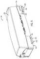
- bedside system 12includes a cassette 300 configured to be mounted to a motor drive base 302 .
- FIG. 3shows a bottom perspective view of cassette 300 prior to mounting to motor drive base 302 .
- Motor drive base 302includes a first capstan 304 , a second capstan 306 , and a third capstan 308
- cassette 300includes a first capstan socket 310 , a second capstan socket 312 , and a third capstan socket 314 .
- Cassette 300includes a housing 316 , and housing 316 includes a base plate 318 .
- Each of the capstan socketsis configured to receive one of the capstans of motor drive base 302 .
- base plate 318includes a hole or aperture aligned with each of the capstan sockets 310 , 312 , and 314 to allow each capstan to engage with the appropriate capstan socket.
- the engagement between the capstans and capstan socketsallows the transfer of energy (e.g., rotational movement) generated by one or more actuators (e.g., motors) located within motor drive base 302 to each of the drive mechanisms (discussed below) within cassette 300 .
- a single actuatorprovides energy to each of the drive mechanisms.
- an actuator that drives capstan 304there is an actuator that drives capstan 304 , an actuator that drives capstan 306 , and an actuator that drives capstan 308 .
- the positioning of the capstans and capstan socketshelps the user to align cassette 300 relative to motor drive base 302 by allowing cassette 300 to be mounted to motor drive base 302 only when all three capstan sockets are aligned with the proper capstan.
- the motors that drive capstans 304 , 306 , and 308are located within motor drive base 302 .
- the motors that drive capstans 304 , 306 , and 308may be located outside of base 302 connected to cassette 300 via an appropriate transmission device (e.g., shaft, cable, etc.).
- cassette 300includes motors located within the housing of cassette 300 .
- cassette 300does not include capstan sockets 310 , 312 , and 314 , but includes an alternative mechanism for transferring energy (e.g., rotational motion) from an actuator external to the cassette to each of the cassette drive mechanisms.
- rotational movementmay be transferred to the drive mechanisms of cassette 300 via alternating or rotating magnets or magnetic fields located within motor drive base 302 .
- cassette 300also includes a guide catheter support 311 that supports guide catheter 317 at a position spaced from cassette 300 .
- guide catheter support 311is attached to cassette 300 by a rod 313 .
- Rod 313 and guide catheter support 311are strong enough to support guide catheter 317 without buckling.
- Guide catheter support 311supports guide catheter 317 at a position spaced from the cassette, between the patient and the cassette to prevent buckling, bending, etc. of the portion of guide catheter 317 between the cassette and the patient.
- cassette 300is shown mounted to motor drive base 302 .
- cassette 300includes an outer cassette cover 320 that may be attached to housing 316 .
- outer cassette cover 320When attached to housing 316 , outer cassette cover 320 is positioned over and covers each of the drive mechanisms of cassette 300 .
- outer cassette cover 320acts to prevent accidental contact with the drive mechanisms of cassette 300 while in use.
- cassette 300may be configured to provide for secure (e.g., stabile, rigid, locked, etc.) attachment of cassette 300 to motor drive base 302 .
- motor drive base 302may impart generally upwardly directed forces onto cassette 300 as the various components of motor drive base 302 engage with cassette 300 to provide the functionalities discussed herein.
- Cassette 300may be configured to attach or couple to motor drive base 302 in a way that ensures that cassette 300 remains coupled to motor drive base 302 despite the application of upward forces during use.
- cassette 300may include one or more structures extending from the housing of the cassette that are configured to be received by or within one or more corresponding mating structures on motor drive base 302 in a manner that will resist or prevent upward motion of cassette 300 away from motor drive base 302 .
- cassette 300may include one or more arms or tabs, shown as mounting tabs 600 , extending substantially perpendicular to the plane defined by the side wall of housing 316 .
- cassette 300includes two tabs 600 , one located toward the rear of cassette 300 and one located toward the front of cassette 300 .
- Mounting tabs 600each include an upper surface 604 and a lower surface 606 .
- upper surface 604 and lower surface 606are substantially planar surfaces.
- Upper surface 604is substantially parallel to lower surface 606 , and both are substantially parallel to the lower surface of base plate 318 .
- Mounting tabs 600are positioned along the lower or bottom edge of housing 316 such that lower surface 606 of each tab and the lower surface of base plate 318 form a substantially planar lower surface of cassette 300 .
- Mounting tabs 600are configured to engage or mate with a receiving structure on motor drive base 302 to provide resistance to upward forces generated by motor drive base 302 to help ensure that cassette 300 remains mounted to motor drive base 302 during application of such forces.
- motor drive base 302includes a pair of brackets 602 shown in FIG. 3 .
- the mounting tabs 600are received within brackets 602 such that upper surfaces 604 of the mounting tabs 600 are in contact with the lower surfaces of brackets 602 .
- the contact between upper surfaces 604 and brackets 602tends to resist upward movement of cassette 300 that may otherwise occur without this engagement.
- the resistance of upward movementhelps to ensure proper functioning of cassette 300 by helping to ensure that the proper engagement between cassette 300 and motor drive base 302 is maintained during a procedure.
- FIG. 3shows the receiving structure of motor drive base 302 as a generally u-shaped bracket
- the receiving structuremay include a plurality of recesses formed in the upper surface of motor drive base 302 configured to receive mounting tabs 600 .
- motor drive base 302may include one or more arms that are moveable between and clamped and unclamped positions, and in the clamped position, the moveable arm engages upper surface 604 of each mounting tab 600 such that upward movement of cassette 300 may be resisted.
- guide catheter support 311is shown according to an exemplary embodiment.
- Guide catheter support 311is coupled to the distal end of rod 313 , and, as shown in FIG. 3 , the proximal end of rod 313 is coupled to housing 316 of cassette 300 .
- Guide catheter support 311supports guide catheter 317 at a position spaced from cassette 300 .
- Rod 313 and guide catheter support 311are strong enough to support guide catheter 317 without buckling.
- Guide catheter support 311supports guide catheter 317 to prevent buckling, bending, etc. of the portion of guide catheter 317 between the cassette and the patient.
- Guide catheter support 311includes a body 620 .
- Body 620defines a longitudinal axis that, in the embodiment shown, is substantially perpendicular to the longitudinal axis of rod 313 .
- Body 620includes a first end 622 .
- a guide catheter engaging structure, shown as clamp 624is located adjacent to first end 622 of body 620 .
- Clamp 624is configured to engage guide catheter 317 such that guide catheter 317 is held in position (i.e., prevented from moving) relative to guide catheter support 311 and/or cassette 300 .
- clamp 624includes a pivoting member 626 and a biasing element, shown as spring 628 , engaged between pivoting member 626 and body 620 .
- Spring 628biases clamp 624 into engagement with guide catheter 317 , as shown in FIGS. 6 and 7 .
- pivoting member 626includes an engagement surface, shown as curved recess 630
- body 620includes an engagement surface, shown as curved recess 632 , that is opposed to recess 630 .
- Guide catheter 317is engaged between a lower surface of pivoting member 626 and an upper surface of body 620 such that guide catheter 317 is received within curved recesses 630 and 632 . As shown, in FIGS.
- curved recesses 630 and 632are located between first end 622 and the center point of body 620 (and consequently between first end 622 and second end 636 ), and further, spring 628 is located between first end 622 and recesses 630 and 632 .
- a forcesuch as a force applied by a user's thumb, is applied to the outer end 634 of pivoting member 626 causing compression of spring 628 .
- guide catheter 317is placed within recess 632 of body 620 .
- spring 628expands causing clamp 624 to move to the closed position engaging guide catheter 317 .
- a rotation jointshown as rotatable joint 638 , coupling guide catheter support 311 to rod 313 .
- rotatable joint 638allows body 620 and clamp 624 of guide catheter support 311 to rotate about the longitudinal axis of body 620 .
- arrow line 640indicates the direction of rotation provided by rotatable joint 638 .
- body 620 of guide catheter support 311rotates about an axis substantially perpendicular to a longitudinal axis defined by rod 313 .
- rotatable joint 638allows guide catheter support 311 to accommodate and engage guide catheters 317 positioned at a variety of angles. During a catheterization procedure, the angle at which a guide catheter is positioned may vary due to a number of factors (e.g., size of the patient, location of entry incision, type of guide catheter used, etc.). Thus, rotatable joint 638 allows guide catheter support 311 to accommodate a wider range of guide catheter positions than if guide catheter support 311 did not include a rotatable connection to rod 313 .
- guide catheter support 311may be rotated about the longitudinal axis of guide catheter support 311 via rotatable joint 638 such that the engagement surfaces are able to engage the guide catheter 317 at a plurality of angular positions relative to the patient's body. Specifically, guide catheter support 311 may be rotated such that the engagement surfaces are substantially parallel to the longitudinal axis of guide catheter 317 such that the engagement surfaces engage the outer surface of the guide catheter when clamp 624 is moved to the closed, engaged position.
- guide catheter support 311may be rotated about rotatable joint 638 manually.
- guide catheter support 311 or cassette 300may include an actuator (e.g., a step motor, etc.) that controls the rotational position of guide catheter support 311 .
- controls 16may include a control or user input (e.g., a dial, joystick, touch screen icon, etc.) associated with the guide catheter support 311 such that a user located at workstation 14 may control or change the rotational position of guide catheter support 311 by manipulating the control located at workstation 14 .
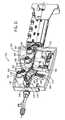
- cassette 300is shown in the “loading” configuration with outer cassette cover 320 removed.
- Cassette 300includes a y-connector support assembly 322 , an axial drive assembly 324 , and a rotational drive assembly 326 .
- the various portions of cassette 300are placed in the loading configuration to allow the user to load or install a guide wire and/or working catheter into cassette 300 .
- y-connector support assembly 322is located in front of axial drive assembly 324
- axial drive assembly 324is located in front of rotational drive assembly 326 within cassette 300 .
- Y-connector support assembly 322includes a chassis 328 and a y-connector restraint 330 .
- Base plate 318includes a support arm 332 that supports y-connector support assembly 322 .
- Chassis 328is coupled to the front of support arm 332 via pin connection 334 .
- a central groove or depression 336extends the length of chassis 328 .
- Y-connector 338rests within central groove 336 of chassis 328 .
- Y-connector 338includes a first leg 340 , a second leg 342 , and a third leg 344 .
- First leg 340is configured to attach to a guide catheter such that the central lumen of the y-connector is in fluid communication with the central lumen of the guide catheter.
- Second leg 342is angled away from the longitudinal axis of y-connector 338 .
- Second leg 342 of y-connector 338allows introduction of a contrast agent or medicine into the lumen of the guide catheter.
- a one way valveprohibits bodily fluid from exiting second leg 342 .
- Third leg 344extends away from the guide catheter toward axial drive assembly 324 .
- guide wire 301 and working catheter 303are inserted into third leg 344 of y-connector 338 via opening 346 and may be advanced through y-connector 338 into the lumen of the guide catheter.
- the third legalso includes a one way valve that permits insertion and removal of the working catheter and guide wire but prohibits bodily fluids from exiting third leg 344 .
- Chassis 328is rotatable about an axis defined by pin connection 334 to allow chassis 328 to be placed in the “loading position” shown in FIG. 8 .
- chassis 328In the loading position, chassis 328 is positioned at about a 45 degree angle, shown by angle line 315 , relative to support arm 332 .
- Chassis 328is moved to the “loading position” to provide easier access to opening 346 of the third leg 344 allowing the user to feed guide wire 301 and working catheter 303 into y-connector 338 .
- Y-connector support assembly 322includes y-connector restraint 330 .
- Y-connector restraint 330is configured to releasably engage y-connector 338 .
- engagement arm 348 of y-connector restraint 330engages or presses y-connector 338 into central groove 336 to securely hold y-connector 338 .
- Y-connector restraint 330may be moved to a disengaged position to release y-connector 338 from chassis 328 .
- Cassette 300also includes an axial drive assembly 324 .
- Axial drive assembly 324includes a first axial drive mechanism, shown as guide wire axial drive mechanism 350 , and a second axial drive mechanism, shown as working catheter axial drive mechanism 352 .
- Axial drive assembly 324also includes a top deck 354 , a cover 356 , and a latch or handle 358 .
- guide wire axial drive mechanism 350is configured to releasably engage and drive (e.g., to impart motion to) guide wire 301 along its longitudinal axis. In this manner, guide wire axial drive mechanism 350 provides for advancement and/or retraction of guide wire 301 .
- Working catheter axial drive mechanism 352is configured to releasably engage and drive (e.g., to impart motion to) working catheter 303 along its longitudinal axis. In this manner, working catheter axial drive mechanism 352 provides for advancement and/or retraction of working catheter 303 .
- Top deck 354is mounted to a central portion 360 of base plate 318 .
- Top deck 354includes a guide wire channel 364 and a working catheter drive channel 366 .
- Guide wire channel 364is positioned generally perpendicular to the top surface of top deck 354 and runs the length of top deck 354 in the longitudinal direction.
- Working catheter drive channel 366is positioned generally perpendicular to the top surface of top deck 354 and is located at an angle relative to guide wire channel 364 .
- a plurality of tabs 368extend vertically from the top surface of top deck 354 along guide wire channel 364 .
- cover 356is shown in the open position. Handle 358 is moved to a position generally parallel to the longitudinal axis of cassette 300 to allow cover 356 to move to the open position. Cover 356 is mounted to top deck 354 via hinges 370 .
- Cassette 300includes a restraint structure that acts to restrain movement of the guide wire when cover 356 is in the closed position. As shown, the restraint structure includes a plurality of tabs 372 extending from the lower surface of cover 356 .
- Tabs 372are positioned such that when cover 356 is closed, tabs 372 are positioned within a portion of guide wire channel 364 between tabs 368 such that tabs 372 restrain movement of guide wire 301 in a vertical direction (i.e., restrains movement of the guide wire in a direction perpendicular to the top surface of top deck 354 ).
- both guide wire axial drive mechanism 350 and working catheter axial drive mechanism 352are exposed allowing the user to load cassette 300 with a guide wire and working catheter.
- guide wire 301is loaded into axial drive assembly 324 by placing the guide wire into guide wire channel 364 .
- Tabs 368facilitate the placement of guide wire 301 by aiding the user in aligning the guide wire with guide wire channel 364 .
- working catheter 303is loaded into axial drive assembly 324 by placing the working catheter into working catheter drive channel 366 .
- Both top deck 354 and central portion 360 of base plate 318are shaped to define a recess 374 .
- Working catheter drive channel 366includes an opening 376 located within recess 374 .
- Recess 374allows opening 376 to be closer to y-connector 338 and also closer to the entry incision in the patient allowing working catheter 303 to be advanced farther into the patient's vascular system than if opening 376 were located further away from y-connector 338 or the entry incision.
- working catheter 303includes a hub 305 at its proximal end that is too large to fit through opening 376 . Thus, the closer that opening 376 is to y-connector 338 and to the entry incision the further working catheter 303 can be advanced into the patient's vascular system.
- cassette 300may be configured to facilitate the performance of a catheter-based medical procedure with more than one working catheter device. For example, a procedure using cassette 300 may be performed using a first working catheter and second working catheter.
- cassette 300may include a third channel, shown as secondary channel 650 , configured to receive and hold a working catheter when the working catheter is not positioned within working catheter drive channel 366 .
- secondary channel 650is not a channel associated with a drive mechanism and does not include a structure to engage and to impart motion to the catheter device while the catheter device is located within secondary channel 650 .
- cassette 300includes secondary channel 650 formed in top deck 354 of axial drive assembly 324 .
- Secondary channel 650is located in front of working catheter drive channel 366 , and, specifically, in the embodiment shown, secondary channel 650 is located between y-connector support assembly 322 and working catheter drive channel 366 .
- secondary channel 650provides a storage or holding location for a second working catheter device, when a different working catheter device is engaged within working catheter drive channel 366 .
- secondary channel 650is positioned generally perpendicular to the top surface of top deck 354 , intersects guide wire channel 364 near the front end of guide wire channel 364 and is located at an angle relative to guide wire channel 364 .
- Secondary channel 650includes an opening 652 located through the sidewall of the housing of cassette 300 . In the embodiment shown, opening 652 is located in front of recess 374 and also in front of opening 376 of working catheter drive channel 366 .
- secondary channel 650is curved, and, in another embodiment, secondary channel 650 may be a substantially straight channel.
- cassette 300may include a series of additional restraint structures, shown as tab 654 , tab 656 and tab 658 .
- Tab 654 , tab 656 and tab 658extend from the lower surface of cover 356 .
- tab 654acts to restrain movement of a working catheter within secondary channel 650 in the vertical direction (i.e., restrains movement of the working catheter in a direction perpendicular to the top surface of top deck 354 ).
- Tab 656 and tab 658act to restrain movement of a working catheter within working catheter drive channel 366 in the vertical direction (i.e., restrains movement of the working catheter in a direction perpendicular to the top surface of top deck 354 ).
- tab 656is received near the front end of working catheter drive channel 366 (i.e., the portion of working catheter drive channel 366 adjacent to guide wire channel 364 )
- tab 658is received near the rear end of working catheter drive channel 366 (i.e., the portion of working catheter drive channel 366 adjacent opening 376 ).
- Cassette 300also includes a rotational drive assembly 326 .
- Rotational drive assembly 326includes a rotational drive mechanism, shown as guide wire rotational drive mechanism 380 , a cover 384 , and a journal 388 .
- Guide wire rotational drive mechanism 380includes a chassis 382 and an engagement structure 386 .
- Rotational drive assembly 326is configured to cause guide wire 301 to rotate about its longitudinal axis.
- Engagement structure 386is configured to releasably engage guide wire 301 and to apply sufficient force to guide wire 301 such that guide wire 301 is allowed to rotate about its longitudinal axis while permitting guide wire 301 to be moved axially by guide wire axial drive mechanism 350 .
- rotational drive assembly 326is supported within housing 316 such that rotation drive assembly 326 is permitted to rotate within housing 316 .
- Engagement structure 386applies sufficient force to guide wire 301 that the rotation of rotation drive assembly 326 causes guide wire 301 to rotate about its longitudinal axis as rotational drive assembly 326 rotates.
- Chassis 382includes a guide wire channel 390 .
- Guide wire channel 390is positioned generally perpendicular to the top surface of chassis 382 and runs the length of chassis 382 in the longitudinal direction.
- a plurality of tabs 392extend vertically from the top surface of chassis 382 along guide wire channel 390 .
- cover 384is shown in the open position. Cover 384 is mounted to chassis 382 via hinge 394 .
- Cassette 300includes a restraint structure that acts to restrain movement of the guide wire when cover 384 is in the closed position. As shown, the restraint structure includes a plurality of tabs 396 extending from the lower surface of cover 384 .
- the top surface of chassis 382includes a plurality of recesses 398 configured to receive tabs 396 when cover 384 is in the closed position.
- Tabs 396are positioned such that when cover 384 is closed, tabs 396 are positioned over guide wire channel 390 such that tabs 396 prevent guide wire 301 from falling out of guide wire channel 390 (i.e., restrains movement of the guide wire in a direction perpendicular to the top surface of chassis 382 ).
- the sidewalls of guide wire channel 390 and the engagement surfaces of wheels 522 and 524prevent or restrain movement of guide wire 301 in other directions perpendicular to the longitudinal axis of guide wire 301 .
- tabs 392 and guide wire channel 390hold guide wire 301 within channel 390 during rotation of rotational drive assembly 326 .
- guide wire channel 390When cover 384 is in the open position, guide wire channel 390 is exposed allowing the user to load cassette 300 with a guide wire. With cover 384 open, guide wire 301 is loaded into rotational drive assembly 326 by placing the guide wire into guide wire channel 390 . Tabs 392 facilitate the placement of guide wire 301 by aiding the user in aligning the guide wire with guide wire channel 390 . As will be described in more detail below, once guide wire 301 is positioned within guide wire channel 390 engagement surfaces of engagement structure 386 are brought into engagement with the guide wire.
- rotational drive assembly 326is automatically rotated such that guide wire channel 390 is facing generally upward to allow for easy loading or removal of guide wire 301 .
- cassette 300is a modular cassette that allows various components of cassette 300 to be removed and/or switched out with other components.
- a usermay wish to control the guide wire using bedside system 12 and to control the working catheter manually.
- a usermay mount only guide wire axial drive mechanism 350 and rotational drive assembly 326 within housing 316 of cassette 300 .
- a usermay wish to control the working catheter using bedside system 12 and to control the guide wire manually.
- a usermay mount only working catheter drive mechanism 352 within housing 316 of cassette 300 .
- cassette 300may include additional locations for mounting drive mechanisms for any type of additional catheter devices that may be used during a procedure. For example, a user may be able to couple drive mechanisms to cassette 300 to control the movement and/or control of an intravascular ultrasound catheter.
- cassette 300is shown in the “loaded” or “use” position.
- y-connector support assembly 322is rotated downward such that y-connector 338 is aligned with guide wire channel 364 of axial drive assembly 324 .
- the axial alignmentallows guide wire 301 and working catheter 303 to be moved into and/or out of y-connector 338 via operation of guide wire axial drive mechanism 350 and working catheter axial drive mechanism 352 .
- Cover 356is shown in the closed position overlying both the guide wire axial drive mechanism 350 and the working catheter axial drive mechanism 352 .
- cover 356also covers guide wire channel 364 , working catheter drive channel 366 and secondary channel 650 . As such, cover 356 acts to prevent interference with the various components of axial drive assembly 324 during use.
- cassette 300During use of cassette 300 to perform a catheter based medical procedure, guide wire 301 and working catheter 303 are moved into the patient's body (typically, into an artery of the patient) and various fluids (e.g., contrast agent, medicine, etc.) may be delivered into the patient via the guide catheter.
- various fluidse.g., contrast agent, medicine, etc.
- guide wire 301 and working catheter 303typically will come into contact with bodily fluids (e.g., blood) or other fluids (e.g., contrast agent) administered to the patient during the procedure.
- cassette 300is equipped with a structure configured to remove fluid from the outer surfaces of guide wire 301 and working catheter 303 as the guide wire or catheter is retracted from the patient and back into cassette 300 .
- Such a structuredecreases the amount of fluid that remains on the guide wire and working catheter as they come into contact with the wheels of the various drive assemblies. Because the presence of fluid on the outer surface of the guide wire or catheter may impact the transmission of motion from the drive assemblies to the devices, limiting or preventing the amount of fluid that remains on the devices as they enter cassette 300 may improve the performance of cassette 300 .
- the proximal end of y-connector 338may include a ring element 662 that includes an inner surface that is in contact with the outer surface of guide wire 301 and working catheter 303 .
- the inner surface of ring element 662acts to wipe fluid from the outer surface of guide wire 301 and working catheter 303 as the devices are retracted back into cassette 300 .
- the inner surface of ring element 662may be formed of a compliant, rubber-like polymer material that pushes or scrapes fluid from the outer surfaces of the devices as the devices are drawn past the surface of ring element 662 .
- the fluid removing ring element 662may be coupled to the outer surface of top deck 354 and may be located at the front of guide wire channel 364 .
- fluid removing ring element 662may be located within cassette 300 in front of the guide wire and working catheter axial drive mechanisms.
- cassette 300may include a first ring element located within guide wire channel 364 configured to remove or wipe fluid from guide wire 301 and a second ring element located within working catheter drive channel 366 configured to remove or wipe fluid from working catheter 303 .
- handle 358is rotated approximately 90 degrees such that a portion of handle 358 is positioned over cover 356 .
- rotation of handle 358 to the closed position shown in FIG. 9causes the engagement surface of the guide wire axial drive mechanism 350 and of the working catheter axial drive mechanism 352 to move together engaging the guide wire and working catheter, respectively.
- cover 384when cassette 300 is moved to the “loaded” position, cover 384 is moved to the closed position overlying rotational drive mechanism 380 and guide wire channel 390 as shown in FIG. 9 . Like cover 356 , cover 384 acts to prevent interference with the various components of rotational drive assembly 326 during use.
- a usermay activate controls (e.g., controls located at workstation 14 ) to cause the various components of cassette 300 to move between the “loading” and “loaded” positions.
- cassette 300may also be configured to allow the user to move the various components of cassette 300 between the “loading” and “loaded” positions manually.
- the longitudinal axis (and the internal lumen) of y-connector 338is aligned with guide wire channel 364 of axial drive assembly and with guide wire channel 390 of rotational drive assembly 326 .
- This alignmentprovides a path extending from the rear of cassette 300 through y-connector 338 into the guide catheter through which the guide wire is advanced or retracted during axial movement of the guide wire.
- components of cassette 300including top deck 354 , chassis 382 , cover 356 , and cover 384 , may be made from a transparent or translucent plastic.
- Some proceduresmay be performed using more than one working catheter (e.g., first working catheter 303 and second working catheter 660 ).
- a second working catheter 660may be positioned within secondary channel 650 while first working catheter 303 is positioned within working catheter drive channel 366 .
- secondary channel 650provides a storage or holding location for a second working catheter while the first working catheter is engaged within working catheter drive channel 366 .
- secondary channel 650holds the second working catheter while the user is manipulating the first working catheter with cassette 300 .
- cover 356is moved to the open position.
- Second working catheter 660is then moved from secondary channel 650 to the working catheter drive channel 366 , and first working catheter 303 is moved from working catheter drive channel 366 to secondary channel 650 .
- Cover 356is then closed causing the second working catheter to be engaged within working catheter drive channel 366 to allow the user to control second working catheter 660 via cassette 300 .
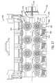
- FIG. 10an exploded perspective view from above of axial drive assembly 324 is shown.
- FIG. 10generally depicts the components of axial drive assembly 324 .
- Guide wire axial drive mechanism 350 and working catheter axial drive mechanism 352are positioned above base plate 318 , and top deck 354 is fastened to central portion 360 of base plate 318 above guide wire axial drive mechanism 350 and working catheter axial drive mechanism 352 .
- guide wire axial drive mechanism 350 and working catheter axial drive mechanism 352are generally enclosed within a chamber defined by top deck 354 and central portion 360 of base plate 318 when axial drive assembly 324 is assembled.
- Top deck 354includes a plurality of apertures 362 to receive various portions of both axial drive mechanism 350 and working catheter axial drive mechanism 352 .
- Axial drive mechanism 350includes a drive element 400 , a first roller assembly 402 , a second roller assembly 404 , and a guide wire axial motion sensor assembly, shown as encoder assembly 406 .
- First roller assembly 402 and second roller assembly 404are both mounted within a housing 416 .
- Drive element 400includes a drive shaft 408 , a drive wheel 410 , a bearing 412 , and a screw 414 .
- Drive shaft 408is configured to engage second capstan 306 of motor drive base 302 such that drive shaft 408 and drive wheel 410 rotate in response to rotation of second capstan 306 .
- First roller assembly 402includes an idler wheel or roller 418 , a wheel housing 420 , a bearing 422 , and a spring 424 .
- Drive wheel 410includes an outer or engagement surface 426
- roller 418includes an outer or engagement surface 428 .
- guide wire 301is positioned between drive wheel 410 and roller 418 such that engagement surface 426 of drive wheel 410 and engagement surface 428 of roller 418 are able to engage the guide wire.
- engagement surface 426 and engagement surface 428define a pair of engagement surfaces. The force applied to guide wire 301 by engagement surface 426 and engagement surface 428 is such that drive wheel 410 is able to impart axial motion to guide wire 301 in response to the rotation of drive shaft 408 caused by rotation of second capstan 306 .
- roller 418is rotatably mounted within wheel housing 420 and rotates freely as drive wheel 410 rotates to drive guide wire 301 .
- Spring 424is biased to exert a force onto wheel housing 420 causing roller 418 to engage the guide wire against drive wheel 410 .
- Spring 424is selected, tuned, and/or adjusted such that the proper amount of force is applied to guide wire 301 by engagement surface 426 and engagement surface 428 in the “engaged” position. In other embodiments, additional drive elements may be added as necessary to impart axial motion to the guide wire.
- Second roller assembly 404includes an idler wheel or roller 430 , a wheel housing 432 , a bearing 434 , and a spring 436 .
- Encoder assembly 406includes shaft 438 , magnetic coupling 440 , idler wheel or roller 442 , bearing 444 , and a screw 446 .
- Roller 430includes an outer or engagement surface 448 and roller 442 includes an outer or engagement surface 450 .
- guide wire 301is positioned between roller 430 and roller 442 such that engagement surface 448 of roller 430 and engagement surface 450 of roller 442 are able to engage the guide wire.
- engagement surface 448 and engagement surface 450define a pair of engagement surfaces.
- the force applied to guide wire 301 by engagement surface 448 and engagement surface 450is such that drive wheel 410 is able to pull guide wire 301 past roller 430 and 442 .
- the pair of non-active or idle rollers 430 and 442help support guide wire 301 and maintain alignment of guide wire 301 along the longitudinal axis of cassette 300 .
- Roller 430is rotatably mounted within wheel housing 432
- roller 442is rotatably mounted to shaft 438 . Both rollers 430 and 442 are mounted to rotate freely as drive wheel 410 imparts axial motion to guide wire 301 .
- Spring 436is biased to exert a force onto wheel housing 432 causing roller 430 to engage guide wire 301 against roller 442 .
- Spring 436is selected, tuned, and/or adjusted such that the proper amount of force is applied to guide wire 301 by engagement surface 448 and engagement surface 450 in the “engaged” position to support the guide wire while still allowing the guide wire to be moved axially by drive wheel 410 .
- spring 424 and spring 436are selected or adjusted such that the force applied to guide wire 301 by wheels 430 and 442 is approximately the same as the force applied to guide wire 301 by wheels 410 and 418 .
- Encoder assembly 406includes magnetic coupling 440 that engages a magnetic encoder located within motor drive base 302 .
- the magnetic encoderis configured to measure an aspect (e.g., speed, position, acceleration, etc.) of axial movement of the guide wire.
- shaft 438rotates causing magnetic coupling 440 to rotate.
- the rotation of magnetic coupling 440causes rotation of the magnetic encoder within motor drive base 302 .
- the magnetic encoder within motor drive base 302is able to provide a measurement of the amount of axial movement experienced by guide wire 301 during a procedure.
- This informationmay be used for a variety of purposes. For example, this information may be displayed to a user at workstation 14 , may be used in a calculation of or estimated position of the guide wire within the vascular system of a patient, may trigger an alert or alarm indicating a problem with guide wire advancement, etc.
- first roller assembly 402 and second roller assembly 404are both mounted within a housing 416 .
- Housing 416provides a common support for first roller assembly 402 and second roller assembly 404 .
- first roller assembly 402 and second roller assembly 404are moved away from drive wheel 410 and roller 442 , respectively, when axial drive assembly 324 is placed in the “loading” configuration.
- Housing 416allows first roller assembly 402 and second roller assembly 404 to be moved together (e.g., in sync) away from drive wheel 410 and roller 442 , respectively, when axial drive assembly 324 is placed in the “load” configuration.
- Axial drive assembly 324also includes working catheter axial drive mechanism 352 .
- Working catheter axial drive mechanism 352includes a drive element 452 and a working catheter axial motion sensor assembly, shown as working catheter encoder assembly 454 .
- Drive element 452includes a drive shaft 456 , a drive wheel 458 , a bearing 460 , and a screw 462 .
- Drive shaft 456is configured to engage first capstan 304 of motor drive base 302 such that drive shaft 456 and drive wheel 458 rotate in response to rotation of first capstan 304 .
- Encoder assembly 454includes shaft 464 , a roller 466 , an encoder linkage 468 , a spring 470 , and a magnetic coupling 480 .
- Drive wheel 458includes an outer or engagement surface 472 and roller 466 includes an outer or engagement surface 474 .
- a working catheteris positioned between drive wheel 458 and roller 466 , such that engagement surface 472 and engagement surface 474 are able to engage working catheter 303 .
- engagement surfaces 472 and 474define a pair of engagement surfaces.
- the force applied to working catheter 303 by engagement surfaces 472 and 474is such that drive wheel 458 is able to impart axial motion to the working catheter in response to the rotation of drive shaft 456 caused by rotation of first capstan 304 .
- This axial motionallows a user to advance and/or retract a working catheter via manipulation of controls located at workstation 14 .
- Roller 466is rotatably mounted to shaft 464 and rotates freely as drive wheel 458 rotates to drive the working catheter.
- Spring 470is coupled to a first end of linkage 468 .
- the second end of linkage 468includes an aperture 476 that is pivotally coupled to a post 478 extending from the inner surface of top deck 354 .
- Spring 470is biased to exert a force on to linkage 468 causing linkage 468 to pivot about post 478 to force roller 466 to engage working catheter 303 against drive wheel 458 .
- Spring 470is selected, tuned, and/or adjusted such that the proper amount of force is applied to working catheter 303 by engagement surfaces 472 and 474 in the “engaged” position to allow drive wheel 458 to impart axial movement to the working catheter.
- Encoder assembly 454includes magnetic coupling 480 that engages a magnetic encoder located within motor drive base 302 .
- the magnetic encoderis configured to measure an aspect (e.g., speed, position, acceleration, etc.) of axial movement of the working catheter.
- shaft 464rotates causing magnetic coupling 480 to rotate.
- the rotation of magnetic coupling 480causes rotation of the magnetic encoder within motor drive base 302 .
- the magnetic encoder within motor drive base 302is able to provide a measurement of the amount of axial movement experienced by the working catheter during a procedure.
- This informationmay be used for a variety of purposes. For example, this information may be displayed to a user at workstation 14 , may be used in a calculation of or estimated position of the working catheter within the vascular system of a patient, may trigger an alert or alarm indicating a problem with working catheter advancement, etc.
- roller 466is moved away from drive wheel 458 when axial drive assembly 324 is placed in the “loading” configuration. This facilitates placement of the working catheter between the opposing pairs of engagement surfaces of working catheter axial drive mechanism 352 .
- cassette 300 and/or motor drive base 302includes a locking mechanism that is configured to lock the position of guide wire 301 during manipulation of the working catheter 303 and to lock the position of working catheter 303 during manipulation of guide wire 301 .
- the locking mechanismacts to increase the force applied to the guide wire by the engagement surfaces when the working catheter is being advanced and to increase the force applied to the working catheter by the engagement surfaces when the guide wire is being advanced.
- top deck 354includes a plurality of cylindrical sleeves, first sleeve 482 , second sleeve 484 , and third sleeve 486 , extending from the inner or lower surface of top deck 354 .
- Top deck 354also includes a plurality of cylindrical collars, first collar 488 , second collar 490 , and third collar 492 , extending from the upper surface of top deck 354 .
- Collar 488is in axial alignment with sleeve 482 .
- Collar 490is in axial alignment with sleeve 484 .
- Collar 492is in axial alignment with sleeve 486 .
- Each of the collars 488 , 490 , and 492define an aperture 362 .
- sleeve 482 and collar 488are configured to receive working catheter drive element 452
- sleeve 484 and collar 490are configured to receive guide wire drive element 400
- sleeve 486 and collar 492are configured to receive guide wire encoder assembly 406 .
- Apertures 362provide access to screws 414 , 446 , and 462 once top deck 354 is mounted over axial drive assembly 324 .
- Top deck 354includes a collar 494 aligned with and located at the back end of guide wire channel 364 .
- Collar 494is configured to receive front shaft 512 that extends from chassis 382 of rotational drive assembly 326 .
- Collar 494is configured to allow front shaft 512 (and consequently the rest of rotational drive assembly 326 ) to rotate about the longitudinal axis of guide wire channel 390 relative to axial drive assembly 324 .
- rotational drive assembly 326is able to rotate relative to housing 316 of cassette 300 while axial drive assembly 324 does not rotate relative to housing 316 .
- both rotational drive assembly 326 and axial drive assembly 324rotate relative to housing 316 of cassette 300 .
- FIG. 11is a bottom perspective view of cassette 300 showing top deck 354 mounted above guide wire axial drive mechanism 350 and working catheter axial drive mechanism 352 .
- FIG. 11shows working catheter drive element 452 , guide wire drive element 400 , and guide wire encoder assembly 406 received within sleeves 482 , 484 , and 486 .
- a support structure 496extends from the lower surface of top deck 354 .
- Spring 470is coupled at one end to support structure 496 allowing spring 470 to compress and expanded between linkage 468 and support structure 496 .
- the lower end of drive shaft 408includes a keyed recess 498
- the lower end of drive shaft 456includes a keyed recess 500
- Keyed recess 500is one embodiment of first capstan socket 310
- keyed recess 498is one embodiment of second capstan socket 312
- Keyed recess 500is configured to receive a capstan, such as first capstan 304
- keyed recess 498is configured to receive a capstan, such as second capstan 306 .
- First capstan 304 and second capstan 306are keyed to fit within keyed recess 500 and 498 and to engage and turn drive shafts 456 and 408 upon rotation of the capstans.
- magnetic coupling 440 of guide wire encoder assembly 406includes a circular array of magnets 504 .
- Magnetic coupling 480 of working catheter encoder assembly 454includes a circular array of magnets 506 .
- Magnetic couplings 440 and 480engage with magnetic encoders positioned within motor drive base 302 .
- the magnetic encoders of motor drive base 302are coupled to appropriate electronics to detect and measure rotation of rollers 442 and 466 and to calculate axial motion of guide wire 301 and working catheter 303 based on the measured rotations. While this embodiment discloses the use of magnetic encoders to detect the axial motion of the guide wire and working catheter, other sensors may be used.
- axial motion of the guide wiremay be detected by an optical sensor that detects movement of the guide wire and/or working catheter by scanning the surface of the guide wire and/or working catheter as it passes the optical sensor.
- the optical sensorincludes an LED light source and a detector (e.g., a complimentary metal oxide semiconductor, other light detecting circuitry, etc.) that detects light reflected off the surface of the guide wire and/or working catheter, and the light detected by the detector is analyzed (e.g., by a digital signal processor) to determine movement of the guide wire and/or working catheter.
- the surface of the guide wire and/or working cathetermay include indicia that are detected to determine axial movement of the guide wire.
- other types of sensorse.g., resolvers, sychros, potentiometers, etc.
- Cassette 300also includes a series of magnets 508 positioned below guide wire channel 364 . Because, in at least some embodiments, the guide wire is made from a magnetic material, magnets 508 are able to interact with the guide wire. In this embodiment, the magnetic attraction created by magnets 508 helps the user position guide wire 301 during loading by drawing guide wire 301 into guide wire channel 364 . The magnetic attraction created by magnets 508 also tends to hold guide wire 301 within guide wire channel 364 during advancement and/or retraction of the guide wire. Further, magnets 508 help to hold guide wire 301 straight (i.e., parallel to the longitudinal axis of guide wire channel 364 ) to aid in the axial movement caused by guide wire axial drive mechanism 350 .
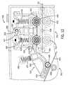
- FIG. 12shows a top view of axial drive assembly 324 in the “loading” configuration with handle 358 (shown in broken lines) rotated such that handle 358 is generally parallel to guide wire channel 364 .
- FIG. 13shows a top view of axial drive assembly 324 in the “loaded” or “use” configuration with handle 358 rotated such that it is generally perpendicular to guide wire channel 364 .
- handle 358is moved from the position of FIG. 13 to the position of FIG. 12 , the engagement surfaces of both guide wire axial drive mechanism 350 and working catheter axial drive mechanism 352 are moved away from each other increasing the space between the pairs of wheels in the drive mechanisms.
- handle 358is coupled to a shaft 357 .
- Shaft 357includes a cam section 359 and housing 416 includes a cam surface 417 .
- cam section 359 of shaft 357moves along cam surface 417 causing housing 416 to move toward guide wire 301 .
- This motionengages guide wire 301 between drive wheel 410 and roller 418 and between roller 430 and roller 442 .
- springs 424 and 436are compressed to the proper tension to allow drive wheel 410 to move guide wire 301 axial along its longitudinal axis.
- housing 416includes a tab 419 that is coupled to linkage 468 .
- linkage 468rotates about post 478 when housing 416 is moved to the position shown in FIG. 12 .
- This movementdraws roller 466 away from working catheter drive wheel 458 .
- roller 466is moved toward catheter drive wheel 458 such that the engagement surfaces of roller 466 and drive wheel 458 engage working catheter 303 .
- cassette 300is configured to allow the user to move the axial drive assembly 324 between the “use” and “loading” positions via manipulation of controls at workstation 14 .
- Cassette 300may also be configured to allow the user to move the axial drive assembly 324 between the “use” and “loading” position manually.
- FIGS. 14 and 15show a perspective view of rotational drive assembly 326 showing cover 384 in the open position.
- Rotational drive assembly 326includes rotational drive mechanism 380 , chassis 382 , an engagement structure 386 , and a disengagement assembly 510 .
- Chassis 382fits over engagement structure 386 and provides mounting for various components of rotational drive assembly 326 .
- Chassis 382includes a front shaft 512 and a rear shaft 514 . As discussed above, front shaft 512 is rotatably received within collar 494 of top deck 354 , and rear shaft 514 is rotatably received within collar 516 such that rotational drive mechanism 380 is able to rotate relative to journal 388 .
- collar 516extends through and is supported by journal 388 such that rear shaft 514 rotates within collar 516 as rotational drive mechanism 380 is rotated.
- Collar 516rests within a recess or slot formed within journal 388 .
- rear shaft 514may be in direct contact with journal 388 such that rear shaft 514 rotates within the recess or slot of journal 388 as rotational drive mechanism 380 is rotated.
- Guide wire channel 390extends the length of chassis 382 through both front shaft 512 and rear shaft 514 .
- Rotational drive mechanism 380includes rotation bevel gear 518 that engages a drive gear 520 .
- Bevel gear 518is rigidly coupled to front shaft 512 of chassis 382 such that rotation of bevel gear 518 rotates chassis 382 .
- Drive gear 520is coupled to a rotational actuator positioned in motor drive base 302 and engages bevel gear 518 .
- Rotation of the rotational actuator in motor drive base 302causes drive gear 520 to rotate which causes bevel gear 518 to rotate which in turn causes rotational drive mechanism 380 to rotate.
- Rotational drive mechanism 380is allowed to rotate about the longitudinal axis of guide wire channel 390 via the rotatable connections between front shaft 512 and top deck 354 and between rear shaft 514 and journal 388 .
- Bevel gear 518further includes a slot 519 in axial alignment with guide wire channel 390 .
- Slot 519allows the user to place guide wire 301 into guide wire channel 390 by dropping it in vertically as opposed to threading it through bevel gear 518 .
- rotational drive assembly 326is equipped with one or more sensors that are configured to measure an aspect (e.g., speed, position, acceleration, etc.) of rotation of the guide wire and/or any other structure of rotational drive assembly 326 .
- the sensors that measure rotation of the guide wiremay include magnetic encoders and/or optical sensors as discussed above regarding the sensors that measure axial motion of the guide wire and/or working catheter. However, any suitable sensor (e.g., resolvers, sychros, potentiometers, etc.) may be used to detect rotation of the guide wire.
- engagement structure 386is shown according to an exemplary embodiment.
- engagement structure 386includes four pairs of idler wheels or rollers. Each pair of rollers includes a fixed wheel 522 and an engagement wheel 524 .
- Fixed wheels 522are rotatably coupled to chassis 382 via fixation posts 530 .
- Each engagement wheel 524is part of an engagement wheel assembly 523 .
- Each engagement wheel assembly 523includes a pivot yoke 532 and a spring 536 .
- Each engagement wheelis mounted to pivot yoke 532 via a mounting post 538 .
- Each pivot yoke 532is pivotally coupled to chassis 382 via fixation posts 534 .
- Each fixed wheel 522includes an outer or engagement surface 526 and each engagement wheel 524 includes an outer or engagement surface 528 .
- FIG. 14shows engagement structure 386 in the “use” or “engaged” position.
- guide wire 301is positioned between fixed wheels 522 and engagement wheels 524 such that engagement surfaces 526 and 528 are able to engage guide wire 301 .
- engagement surface 526 and engagement surface 528 of each pair of rollersdefine a pair of engagement surfaces.
- the force applied to guide wire 301 by engagement surfaces 526 and 528is sufficient to cause the guide wire to rotate about its longitudinal axis as rotational drive assembly 326 is rotated. Further, the force applied to guide wire 301 by engagement surfaces 526 and 528 is also sufficient to allow the guide wire to be moved axially by guide wire axial drive mechanism 350 .
- Springs 536are biased to exert a force onto pivot yokes 532 causing each engagement wheel 524 to engage the opposite fixed wheel 522 .
- the generally L-shape of pivot yoke 532allows springs 536 to be aligned with the longitudinal axis of guide wire 301 and still cause engagement between engagement wheels 524 , fixed wheels 522 , and the guide wire. This allows the lateral dimension of rotational drive assembly 326 to be less than if springs 536 were positioned perpendicular to the longitudinal axis of the guide wire.
- Springs 536are selected, tuned, and/or adjusted such that the proper amount of force is applied to the guide wire by engagement surfaces 526 and 528 in the “engaged” position.
- Cassette 300also includes a series of magnets 540 located beneath guide wire channel 390 . Because, in at least some embodiments the guide wire is made from a magnetic material, magnets 540 are able to interact with the guide wire. In this embodiment, the magnetic attraction created by magnets 540 helps the user position guide wire 301 during loading by drawing guide wire 301 into guide wire channel 390 . The magnetic attraction created by magnets 540 also tends to hold guide wire 301 within guide wire channel 390 during advancement and/or retraction of the guide wire. Further, magnets 540 help to hold guide wire 301 straight (i.e., parallel to the longitudinal axis of guide wire channel 390 ) to aid in the axial movement caused by guide wire axial drive mechanism 350 .
- Rotational drive assemblyalso includes a disengagement assembly 510 .
- Disengagement assembly 510includes a stepped collar 542 , a base plate 544 , and a spring 546 .
- Stepped collar 542is coupled to base plate 544
- spring 546is coupled at one end to chassis 382 and at the other end to base plate 544 .
- Stepped collar 542includes a slot 548 in axial alignment with guide wire channel 390 . Like slot 519 , slot 548 allows the user to place guide wire 301 into guide wire channel 390 by dropping it in vertically as opposed to threading it through stepped collar 542 .
- Base plate 544includes a plurality of engagement arms 550 that extend generally perpendicular to the plane defined by base plate 544 .
- disengagement assembly 510allows engagement wheels 524 to be moved away from fixed wheels 522 .
- FIG. 17shows a top view of rotational drive assembly 326 in the “loading” configuration
- FIG. 16shows a top view of rotational drive assembly 326 in the “loaded” or “use” configuration.
- an axially directed force(depicted by the arrow in FIG. 17 ) is applied to stepped collar 542 . This causes base plate 544 to move toward the front of cassette 300 in the direction of the arrow. As base plate 544 moves forward, spring 546 is compressed, and engagement arms 550 are brought into contact with pivot yokes 532 .
- engagement arms 550 and pivot yokes 532causes springs 536 to be compressed, and pivot yokes 532 pivot about fixation posts 534 .
- engagement wheels 524are drawn away from fixed wheels 522 . As shown in FIG. 17 , this provides sufficient space between engagement wheels 524 and fixed wheels 522 to allow the user to place guide wire 301 into guide wire channel 390 .
- engagement wheels 524move from the position shown in FIG. 17 to the “engaged” position shown in FIG. 16 .
- spring 546 and springs 536are allowed to expand causing engagement arms 550 to disengage from pivot yokes 532 .
- Pivot yokes 532pivot counter-clockwise about fixation posts 534 , bringing engagement wheels 524 back toward guide wire channel 390 causing engagement surfaces 526 of fixed wheels 522 and engagement surfaces 528 of engagement wheels 524 to engage guide wire 301 .
- a usermay activate controls located at workstation 14 to cause rotational drive assembly 326 to move between the “use” position and the “loading” position.
- rotational drive assembly 326is automatically rotated such that guide wire channel 390 is facing generally upward to allow for easy loading or removal of the guide wire.
- chassis 382rotates relative to stepped collar 542 .
- a path defined by the engagement surfaces of engagement structure 386 and guide wire channel 390align with slot 548 of stepped collar 542 .
- Motor drive base 302may also include a structure (e.g., two rods, etc.) that applies the axial force to stepped collar 542 in response to a user's activation of controls located at workstation 14 .
- the structureapplies the axial force to the stepped collar 542 to cause engagement structure 386 to disengage from the guide wire.
- cover 384is moved from the closed position to the open position allowing the user to access guide wire channel 390 to either remove or install the guide wire.
- cassette 300 and/or motor drive base 302includes motors or other actuators that cause the covers of cassette 300 to open in response to a user's activation of controls at workstation 14 .
- cassette 300may be configured to facilitate transfer or replacement of a guide wire during a catheter procedure.
- FIG. 18a rear perspective view of cassette 300 with outer cassette cover 320 attached is shown, according to an exemplary embodiment.
- cassette 300includes a secondary support assembly, shown as guide wire support structure 670 , coupled to and extending above the upper edge of journal 388 .
- Support structure 670provides a storage or holding location to hold a guide wire while a user either loads a different guide wire into cassette 300 or removes a different guide wire from cassette 300 . In this manner, support structure 670 provides a convenient location to place one guide wire while the user of the cassette is occupied with adding or removing another guide wire from cassette 300 .
- Support structure 670includes an outer housing 672 and an insert 674 positioned within outer housing 672 . Together, outer housing 672 and insert 674 are shaped to define a channel 676 configured to receive a guide wire. As shown, the upper portions of outer housing 672 and insert 674 are angled defining an angled, “V-shaped” upper section 680 of channel 676 , and the lower portions of outer housing 672 and insert 674 are shaped defining a lower, vertically oriented slot 678 . A guide wire may be placed into and supported within channel 676 , while the user handles a second guide wire. In the embodiment shown, the upper angled section 680 of channel 676 helps guide the guide wire into channel 676 , and the guide wire is held within slot 678 . In one embodiment, insert 674 may be made from a compliant material (e.g., a polymer material, rubber, etc.) that helps grip the guide wire without damaging or altering the outer surface of the guide wire.
- a compliant materiale.g., a poly
Landscapes
- Health & Medical Sciences (AREA)
- Surgery (AREA)
- Engineering & Computer Science (AREA)
- Life Sciences & Earth Sciences (AREA)
- Biomedical Technology (AREA)
- Robotics (AREA)
- Nuclear Medicine, Radiotherapy & Molecular Imaging (AREA)
- Heart & Thoracic Surgery (AREA)
- Medical Informatics (AREA)
- Molecular Biology (AREA)
- Animal Behavior & Ethology (AREA)
- General Health & Medical Sciences (AREA)
- Public Health (AREA)
- Veterinary Medicine (AREA)
- Media Introduction/Drainage Providing Device (AREA)
Abstract
Description
Claims (14)
Priority Applications (1)
| Application Number | Priority Date | Filing Date | Title |
|---|---|---|---|
| US13/232,624US9833293B2 (en) | 2010-09-17 | 2011-09-14 | Robotic catheter system |
Applications Claiming Priority (2)
| Application Number | Priority Date | Filing Date | Title |
|---|---|---|---|
| US38418710P | 2010-09-17 | 2010-09-17 | |
| US13/232,624US9833293B2 (en) | 2010-09-17 | 2011-09-14 | Robotic catheter system |
Publications (2)
| Publication Number | Publication Date |
|---|---|
| US20120179167A1 US20120179167A1 (en) | 2012-07-12 |
| US9833293B2true US9833293B2 (en) | 2017-12-05 |
Family
ID=46455835
Family Applications (1)
| Application Number | Title | Priority Date | Filing Date |
|---|---|---|---|
| US13/232,624Active2032-10-17US9833293B2 (en) | 2010-09-17 | 2011-09-14 | Robotic catheter system |
Country Status (1)
| Country | Link |
|---|---|
| US (1) | US9833293B2 (en) |
Cited By (13)
| Publication number | Priority date | Publication date | Assignee | Title |
|---|---|---|---|---|
| US10687903B2 (en) | 2013-03-14 | 2020-06-23 | Auris Health, Inc. | Active drive for robotic catheter manipulators |
| US11246672B2 (en) | 2019-08-15 | 2022-02-15 | Auris Health, Inc. | Axial motion drive devices, systems, and methods for a robotic medical system |
| US11376401B2 (en) | 2017-04-26 | 2022-07-05 | Acclarent, Inc. | Deflectable guide for medical instrument |
| US11504020B2 (en) | 2019-10-15 | 2022-11-22 | Imperative Care, Inc. | Systems and methods for multivariate stroke detection |
| US20240033017A1 (en)* | 2022-08-01 | 2024-02-01 | Imperative Care, Inc. | Method of robotically driving a multi catheter assembly above the aortic arch |
| US11998287B1 (en) | 2019-03-18 | 2024-06-04 | Dopl Technologies Inc. | Platform for facilitating remote robotic medical procedures |
| US12232838B2 (en) | 2021-08-12 | 2025-02-25 | Imperative Care, Inc. | Method of robotically performing a neurovascular procedure |
| USD1069809S1 (en) | 2022-08-25 | 2025-04-08 | Kandu Health, Inc. | Display screen or portion thereof with graphical user interface |
| US12329397B2 (en) | 2022-08-02 | 2025-06-17 | Imperative Care, Inc. | Fluidics management system |
| US12377206B2 (en) | 2023-05-17 | 2025-08-05 | Imperative Care, Inc. | Fluidics control system for multi catheter stack |
| US12419703B2 (en) | 2022-08-01 | 2025-09-23 | Imperative Care, Inc. | Robotic drive system for achieving supra-aortic access |
| US12433702B2 (en) | 2022-12-01 | 2025-10-07 | Imperative Care, Inc. | Telescoping drive table |
| US12440289B2 (en) | 2022-12-01 | 2025-10-14 | Imperative Care, Inc. | Method of priming an interventional device assembly |
Families Citing this family (30)
| Publication number | Priority date | Publication date | Assignee | Title |
|---|---|---|---|---|
| WO2009137410A1 (en)* | 2008-05-06 | 2009-11-12 | Corindus Ltd. | Catheter system |
| US20140066900A1 (en) | 2012-09-06 | 2014-03-06 | Corindus, Inc. | System for guide catheter control |
| WO2014091380A1 (en) | 2012-12-13 | 2014-06-19 | Koninklijke Philips N.V. | Interventional system |
| WO2014097086A1 (en) | 2012-12-21 | 2014-06-26 | Koninklijke Philips N.V. | Interventional x-ray system with automatic centration of roi in centre of image |
| FR3002852B1 (en) | 2013-03-07 | 2016-04-01 | Robocath | MEDICAL MEMBER TRAINING MODULE EXTENDED |
| WO2014143746A2 (en)* | 2013-03-15 | 2014-09-18 | Corindus, Inc. | Guide wire or working catheter with modified drive surface |
| US10864629B2 (en) | 2013-03-15 | 2020-12-15 | Corindus, Inc. | System and method for controlling a position of an articulated robotic arm |
| US9070486B2 (en)* | 2013-03-15 | 2015-06-30 | Corindus Inc. | Radiation shielding cockpit carrying an articulated robotic arm |
| CN105246411B (en)* | 2013-04-03 | 2019-10-18 | 皇家飞利浦有限公司 | Intervene x-ray system |
| US10549071B2 (en) | 2013-10-15 | 2020-02-04 | Corindus, Inc. | Guide catheter control flexible track |
| CA2946324C (en)* | 2014-05-02 | 2023-03-21 | Intellimedical Technologies Pty Ltd | Elongate steerable devices for insertion into a subject's body |
| FR3022147B1 (en)* | 2014-06-12 | 2016-07-22 | Robocath | ROBOTISE MODULE OF SOFT MEDICAL MEDICAL TRAINING |
| WO2017004307A1 (en) | 2015-06-30 | 2017-01-05 | Corindus, Inc. | System and method for detecting a position of a guide catheter support |
| FR3046543B1 (en)* | 2016-01-07 | 2018-02-02 | Robocath | ROBOTISABLE MODULE FOR DRIVING AN ELONGATED SOFT MEDICAL DEVICE, MEDICAL ROBOT AND SYSTEM COMPRISING SUCH A MODULE |
| FR3066381B1 (en)* | 2017-05-16 | 2019-06-28 | Robocath | PROTECTIVE ENVELOPE FOR A ROBOTIC MODULE FOR DRIVING AN ELONGATED MEDICAL DEVICE WITH A GUIDE TRACK |
| CN107744406B (en)* | 2017-08-30 | 2025-07-11 | 首都医科大学附属北京天坛医院 | A robot operating platform and operating method thereof |
| US10912624B2 (en)* | 2017-09-11 | 2021-02-09 | Corindus, Inc. | System and apparatus for sensing contact on a robotic mechanism in a catheter procedure system |
| US11413063B2 (en)* | 2019-06-18 | 2022-08-16 | Boston Scientific Scimed, Inc. | Atherectomy system with guidewire detection |
| CN114364423B (en)* | 2019-07-19 | 2023-03-31 | 科林达斯公司 | Load sensing of elongate medical devices in robotic actuation |
| WO2022094228A1 (en) | 2020-10-30 | 2022-05-05 | Boston Scientific Scimed, Inc. | Atherectomy burrs with blood flow enhancements |
| US20220183664A1 (en) | 2020-12-10 | 2022-06-16 | Olympus Medical Systems Corporation | Real-time sampling system |
| DE102021102887B3 (en)* | 2021-02-08 | 2022-04-21 | Schölly Fiberoptic GmbH | Coupling device for light guides |
| WO2022212567A1 (en)* | 2021-04-01 | 2022-10-06 | Xcath, Inc. | A guidewire controller cassette and using method thereof |
| US11992278B2 (en)* | 2021-05-10 | 2024-05-28 | Perazah Inc. | Robot for vascular intervention |
| CN113712671B (en)* | 2021-11-02 | 2022-02-08 | 极限人工智能(北京)有限公司 | Automatic engagement method and device for end effector, storage medium and electronic device |
| CN115517779A (en)* | 2022-01-29 | 2022-12-27 | 深圳市爱博医疗机器人有限公司 | A slave driver with cover detection function |
| CN115518264A (en)* | 2022-01-29 | 2022-12-27 | 深圳市爱博医疗机器人有限公司 | Auxiliary clamping device for interventional operation |
| KR20250023392A (en)* | 2022-06-15 | 2025-02-18 | 에드워즈 라이프사이언시스 코포레이션 | Universal stabilizer for transmission systems |
| WO2024003745A1 (en)* | 2022-06-28 | 2024-01-04 | Guido Danieli | New components disposable and multi-use re-sterilizable for the robotic system for endovascular surgery |
| DE102022207877A1 (en) | 2022-07-29 | 2024-02-01 | Siemens Healthcare Gmbh | Method and device for monitoring an interventional procedure |
Citations (216)
| Publication number | Priority date | Publication date | Assignee | Title |
|---|---|---|---|---|
| US2718598A (en) | 1952-04-12 | 1955-09-20 | Graf Herbert | Diagnostic x-ray apparatus |
| US3147953A (en) | 1961-09-15 | 1964-09-08 | Raymond Products Company | Desk lift |
| US3308297A (en) | 1964-02-12 | 1967-03-07 | Joseph S Mansker | X-ray protective shield having an aperture for the passage of instruments manipulated by the operator |
| FR2167098A5 (en) | 1971-12-29 | 1973-08-17 | Siemens Ag | Radiation shielded control console - for x ray installations |
| SU279814A1 (en) | 1968-12-08 | 1975-07-25 | Intracavitary Radiotherapy Apparatus | |
| DE2856439A1 (en) | 1978-12-28 | 1980-07-17 | Wolfgang Dr Med Woeppel | X=ray appts. for angiography with automatic contrast fluid injection - is coordinated with longitudinal movement of patient table and film changer and has punched card coordination system for x=ray tube movement |
| US4254341A (en) | 1978-09-04 | 1981-03-03 | Marianne Herr | Radiation protection device, particularly for medical X-ray, radiation therapy and diagnostic use |
| SU992067A1 (en) | 1981-03-30 | 1983-01-30 | Предприятие П/Я Г-4158 | Drive of injector for angiography |
| US4382184A (en) | 1978-11-24 | 1983-05-03 | Cardiac Imaging Limited Partnership | Apparatus and method for simultaneously displaying relative displacements of a fluctuating biological object |
| US4581538A (en) | 1983-09-30 | 1986-04-08 | Colonial X-Ray Corporation | Radiation shield |
| EP0329492A2 (en) | 1988-02-18 | 1989-08-23 | Bjorn A. J. Angelsen | Laser catheter delivery system |
| EP0331944A1 (en) | 1988-03-07 | 1989-09-13 | Combustion Engineering, Inc. | Inspection probe manipulator |
| US4965456A (en) | 1988-06-08 | 1990-10-23 | Siemens Aktiengesellschaft | Radiation guard means |
| US4977588A (en) | 1989-03-16 | 1990-12-11 | U.S. Philips Corporation | X-ray examination apparatus |
| US5015864A (en) | 1989-09-21 | 1991-05-14 | Maleki Massoud M | Mobile radiation shield |
| US5049147A (en) | 1989-04-06 | 1991-09-17 | Danon Nissim N | Apparatus for computerized laser surgery |
| US5090044A (en) | 1989-10-30 | 1992-02-18 | Kabushiki Kaisha Toshiba | X-ray examination apparatus |
| US5133364A (en) | 1988-06-13 | 1992-07-28 | C. R. Bard, Inc. | Guidewire extension with self-latching detachable connector |
| US5139473A (en) | 1990-10-12 | 1992-08-18 | Omnitron International, Inc. | Apparatus and method for the remote handling of highly radioactive sources in the treatment of cancer |
| US5185778A (en) | 1991-08-13 | 1993-02-09 | Magram Martin Y | X-ray shielding apparatus |
| US5217003A (en) | 1991-03-18 | 1993-06-08 | Wilk Peter J | Automated surgical system and apparatus |
| US5217474A (en) | 1991-07-15 | 1993-06-08 | Zacca Nadim M | Expandable tip atherectomy method and apparatus |
| EP0554986A2 (en) | 1992-02-03 | 1993-08-11 | The Whitaker Corporation | Surface mount outlet |
| WO1993020876A1 (en) | 1992-04-14 | 1993-10-28 | Du-Med B.V. | Electronic catheter displacement sensor |
| EP0590268A1 (en) | 1985-03-22 | 1994-04-06 | Massachusetts Institute Of Technology | Catheter for Laser angiosurgery |
| DE4233323A1 (en) | 1992-10-05 | 1994-04-07 | Wolfgang Daum | Sense-of-touch imitator for minimal invasive surgery - has elastic tubes on surgeon's fingers with measurement conductors leading to capacitive press. transducers |
| US5318541A (en) | 1993-03-02 | 1994-06-07 | Cordis Corporation | Apparatus for catheter exchange in vascular dilitation |
| US5351676A (en) | 1991-08-05 | 1994-10-04 | Putman John M | Endoscope stabilizer |
| US5377678A (en) | 1991-09-03 | 1995-01-03 | General Electric Company | Tracking system to follow the position and orientation of a device with radiofrequency fields |
| US5380338A (en)* | 1992-09-03 | 1995-01-10 | Minnesota Scientific, Inc. | Laparoscope holder with rotatable gripping pads |
| WO1995002233A1 (en) | 1993-07-06 | 1995-01-19 | Cybernet Systems Corporation | Method and system for simulating medical procedures including virtual reality and control method and system for use therein |
| US5396880A (en) | 1992-04-08 | 1995-03-14 | Danek Medical, Inc. | Endoscope for direct visualization of the spine and epidural space |
| US5423321A (en) | 1993-02-11 | 1995-06-13 | Fontenot; Mark G. | Detection of anatomic passages using infrared emitting catheter |
| US5425382A (en) | 1993-09-14 | 1995-06-20 | University Of Washington | Apparatus and method for locating a medical tube in the body of a patient |
| US5434775A (en) | 1993-11-04 | 1995-07-18 | The General Hospital Corporation | Managing an inventory of devices |
| JPH07184923A (en) | 1993-12-28 | 1995-07-25 | Hitachi Ltd | Remote microsurgery support device |
| US5464023A (en) | 1994-01-31 | 1995-11-07 | Cordis Corporation | Magnetic exchange device for catheters |
| JPH07328016A (en) | 1994-06-14 | 1995-12-19 | Olympus Optical Co Ltd | Surgical manipulator system |
| US5484407A (en) | 1993-06-24 | 1996-01-16 | Osypka; Peter | Catheter with steerable distal end |
| US5487734A (en) | 1995-01-10 | 1996-01-30 | Specialized Health Products, Inc. | Self retracting catheter needle apparatus and methods |
| US5492131A (en) | 1994-09-06 | 1996-02-20 | Guided Medical Systems, Inc. | Servo-catheter |
| US5524180A (en) | 1992-08-10 | 1996-06-04 | Computer Motion, Inc. | Automated endoscope system for optimal positioning |
| WO1996021486A1 (en) | 1995-01-12 | 1996-07-18 | Chin Rong Hwang | Single outlet vascular catheterism device |
| US5540649A (en) | 1993-10-08 | 1996-07-30 | Leonard Medical, Inc. | Positioner for medical instruments |
| US5578014A (en) | 1992-04-29 | 1996-11-26 | Erez; Uri | Skin piercing devices for medical use |
| US5584078A (en) | 1994-11-16 | 1996-12-17 | Saboory; Majid | Detachable/disposable face shield for surgical mask |
| US5586968A (en) | 1992-12-15 | 1996-12-24 | Gruendl; Andreas | Method and apparatus for moving an endoscope along a canal-shaped cavity |
| US5623943A (en) | 1992-08-12 | 1997-04-29 | Scimed Life Systems, Inc. | Magnetic medical shaft movement control device and method |
| US5644613A (en) | 1995-08-11 | 1997-07-01 | Cmt-Medical Technologies Ltd. | Road-mapping |
| US5654864A (en) | 1994-07-25 | 1997-08-05 | University Of Virginia Patent Foundation | Control method for magnetic stereotaxis system |
| US5690645A (en) | 1995-06-28 | 1997-11-25 | Cordis Corporation | Device for moving a catheter in a controlled manner |
| US5697377A (en) | 1995-11-22 | 1997-12-16 | Medtronic, Inc. | Catheter mapping system and method |
| US5704897A (en) | 1992-07-31 | 1998-01-06 | Truppe; Michael J. | Apparatus and method for registration of points of a data field with respective points of an optical image |
| US5706827A (en) | 1994-09-21 | 1998-01-13 | Scimed Life Systems, Inc. | Magnetic lumen catheter |
| US5728044A (en) | 1995-03-10 | 1998-03-17 | Shan; Yansong | Sensor device for spacial imaging of endoscopes |
| US5741271A (en) | 1991-11-05 | 1998-04-21 | Nakao; Naomi L. | Surgical retrieval assembly and associated method |
| US5779623A (en) | 1993-10-08 | 1998-07-14 | Leonard Medical, Inc. | Positioner for medical instruments |
| US5821920A (en) | 1994-07-14 | 1998-10-13 | Immersion Human Interface Corporation | Control input device for interfacing an elongated flexible object with a computer system |
| US5827313A (en)* | 1996-09-27 | 1998-10-27 | Boston Scientific Corporation | Device for controlled longitudinal movement of an operative element within a catheter sheath and method |
| US5842987A (en) | 1997-05-20 | 1998-12-01 | Sahadevan; Velayudhan | Simulated patient setup for medical imaging with increased patient throughput |
| US5851182A (en) | 1996-09-11 | 1998-12-22 | Sahadevan; Velayudhan | Megavoltage radiation therapy machine combined to diagnostic imaging devices for cost efficient conventional and 3D conformal radiation therapy with on-line Isodose port and diagnostic radiology |
| US5882333A (en) | 1994-05-13 | 1999-03-16 | Cardima, Inc. | Catheter with deflectable distal section |
| US5957941A (en) | 1996-09-27 | 1999-09-28 | Boston Scientific Corporation | Catheter system and drive assembly thereof |
| US5981964A (en) | 1997-12-22 | 1999-11-09 | Bruce J. McAuley | Adjustable X-ray shield and on-line dosimetry system using same |
| US6004276A (en) | 1997-03-03 | 1999-12-21 | Quinton Instrument Company | Open architecture cardiology information system |
| US6013038A (en) | 1995-01-10 | 2000-01-11 | Advanced Cardiovascular Systems, Inc. | Magnetic guidewire anchoring apparatus and method for facilitating exchange of an over-the-wire catheter |
| EP0970663A1 (en) | 1998-07-10 | 2000-01-12 | Mitsubishi Denki Kabushiki Kaisha | Master/slave system for the manipulation of tubular medical tools |
| US6024749A (en) | 1997-10-27 | 2000-02-15 | Shturman Cardiology Systems, Inc. | Rotational atherectomy device with improved exchangeable drive shaft cartridge |
| US6048300A (en)* | 1997-07-03 | 2000-04-11 | Guidant Corporation | Compact cartridge for afterloader |
| US6083170A (en) | 1996-05-17 | 2000-07-04 | Biosense, Inc. | Self-aligning catheter |
| US6126647A (en) | 1999-05-17 | 2000-10-03 | Hermetic Switch, Inc. | Magnetically guided catheter with sensor |
| US6171234B1 (en)* | 1998-09-25 | 2001-01-09 | Scimed Life Systems, Inc. | Imaging gore loading tool |
| US6233476B1 (en) | 1999-05-18 | 2001-05-15 | Mediguide Ltd. | Medical positioning system |
| US6258052B1 (en) | 1997-11-13 | 2001-07-10 | Lumend, Inc. | Guidewire and catheter with rotating and reciprocating symmetrical or asymmetrical distal tip |
| US6261247B1 (en) | 1998-12-31 | 2001-07-17 | Ball Semiconductor, Inc. | Position sensing system |
| US6266552B1 (en) | 1996-06-28 | 2001-07-24 | Siemens-Elema Ab | Method and arrangement for locating a measurement and/or treatment catheter in a vessel or organ of a patient |
| US6285898B1 (en) | 1993-07-20 | 2001-09-04 | Biosense, Inc. | Cardiac electromechanics |
| US6290675B1 (en) | 1997-01-09 | 2001-09-18 | Endosonics Corporation | Device for withdrawing a catheter |
| US20010025142A1 (en) | 1997-06-13 | 2001-09-27 | Gerd Wessels | Medical examination apparatus with means for acquiring patient and/or apparatus movements |
| WO2001074252A2 (en) | 2000-03-31 | 2001-10-11 | Rita Medical Systems Inc. | Tissue biopsy and treatment apparatus and method |
| WO2002009571A2 (en) | 2000-07-31 | 2002-02-07 | Galil Medical Ltd. | Planning and facilitation systems and methods for cryosurgery |
| US6351513B1 (en) | 2000-06-30 | 2002-02-26 | Siemens Corporate Research, Inc. | Fluoroscopy based 3-D neural navigation based on co-registration of other modalities with 3-D angiography reconstruction data |
| US6358199B1 (en) | 1998-05-06 | 2002-03-19 | Stm Medizintechnik Starnberg Gmbh | Drive means for flexible eversion tube system |
| US6375471B1 (en) | 1998-07-10 | 2002-04-23 | Mitsubishi Electric Research Laboratories, Inc. | Actuator for independent axial and rotational actuation of a catheter or similar elongated object |
| US20020087166A1 (en)* | 1998-02-24 | 2002-07-04 | Brock David L. | Flexible instrument |
| US20020109107A1 (en) | 2000-08-15 | 2002-08-15 | Goldstein James A. | Radiation protection system |
| US20020115931A1 (en) | 2001-02-21 | 2002-08-22 | Strauss H. William | Localizing intravascular lesions on anatomic images |
| WO2002064011A2 (en) | 2001-02-13 | 2002-08-22 | Mediguide Ltd. | Medical imaging and navigation system |
| US6442451B1 (en) | 2000-12-28 | 2002-08-27 | Robotic Workspace Technologies, Inc. | Versatile robot control system |
| US6447504B1 (en) | 1998-07-02 | 2002-09-10 | Biosense, Inc. | System for treatment of heart tissue using viability map |
| US6451027B1 (en)* | 1998-12-16 | 2002-09-17 | Intuitive Surgical, Inc. | Devices and methods for moving an image capture device in telesurgical systems |
| US20020168618A1 (en) | 2001-03-06 | 2002-11-14 | Johns Hopkins University School Of Medicine | Simulation system for image-guided medical procedures |
| US20020177789A1 (en) | 2001-05-06 | 2002-11-28 | Ferry Steven J. | System and methods for advancing a catheter |
| US6497444B1 (en) | 2001-10-10 | 2002-12-24 | Alan Simon | Radiation shield for occupants of golf carts |
| US6499163B1 (en) | 2000-11-08 | 2002-12-31 | Harold Stensby | Apparatus convertible to a chair or treatment table |
| US6522909B1 (en) | 1998-08-07 | 2003-02-18 | Stereotaxis, Inc. | Method and apparatus for magnetically controlling catheters in body lumens and cavities |
| US20030036712A1 (en) | 2001-08-15 | 2003-02-20 | Heh Kok Boon | Roller wheel assisted guidewire advancer |
| US20030040671A1 (en) | 1996-06-17 | 2003-02-27 | Somogyi Christopher P. | Medical tube for insertion and detection within the body of a patient |
| US6540670B1 (en) | 1999-03-19 | 2003-04-01 | Olympus Optical Co., Ltd. | Endoscope system |
| US20030069719A1 (en) | 1998-01-28 | 2003-04-10 | Immersion Medical Inc. | Interface device and method for interfacing instruments to vascular access simulation systems |
| US20030078003A1 (en) | 1999-10-28 | 2003-04-24 | Hunter Mark W. | Surgical communication and power system |
| US6554472B1 (en) | 2001-11-15 | 2003-04-29 | Ge Medical Systems Global Technology | X-ray positioner with lead shield protection device |
| US20030088209A1 (en) | 2000-02-16 | 2003-05-08 | Jessica Chiu | Multi-lumen extrusion tubing |
| US6610007B2 (en) | 2000-04-03 | 2003-08-26 | Neoguide Systems, Inc. | Steerable segmented endoscope and method of insertion |
| US20030176770A1 (en) | 2000-03-16 | 2003-09-18 | Merril Gregory L. | System and method for controlling force applied to and manipulation of medical instruments |
| US20030199848A1 (en) | 1999-09-22 | 2003-10-23 | Ledesma Michelle N. | Methods and apparatuses for radiation treatment |
| US20030210259A1 (en) | 2001-11-14 | 2003-11-13 | Liu Alan V. | Multi-tactile display haptic interface device |
| US20040015974A1 (en) | 2002-03-21 | 2004-01-22 | Sun Microsystems, Inc. | Callback event listener mechanism for resource adapter work executions performed by an application server thread |
| US20040044279A1 (en) | 2002-05-17 | 2004-03-04 | Lewin Jonathan S. | System and method for adjusting image parameters based on device tracking |
| US6705990B1 (en) | 2000-07-25 | 2004-03-16 | Tensys Medical, Inc. | Method and apparatus for monitoring physiologic parameters of a living subject |
| US20040064086A1 (en) | 2002-03-01 | 2004-04-01 | Medtronic-Minimed | Multilumen catheter |
| US20040068173A1 (en) | 2002-08-06 | 2004-04-08 | Viswanathan Raju R. | Remote control of medical devices using a virtual device interface |
| US6726675B1 (en) | 1998-03-11 | 2004-04-27 | Navicath Ltd. | Remote control catheterization |
| US20040085294A1 (en) | 2002-10-31 | 2004-05-06 | Georg Michelitsch | Method for operating a haptic interface unit |
| EP1415660A1 (en) | 2002-10-28 | 2004-05-06 | Biosense, Inc. | Homing donor cells to a target zone in tissue for delivery of translocation stimulators |
| US6740103B2 (en) | 1998-10-02 | 2004-05-25 | Stereotaxis, Inc. | Magnetically navigable and/or controllable device for removing material from body lumens and cavities |
| US20040113498A1 (en) | 2002-12-12 | 2004-06-17 | Thomas Kroenke | Electrical isolation interface for medical instrumentation |
| US20040138548A1 (en) | 2003-01-13 | 2004-07-15 | Mediguide Ltd. | Method and system for registering a medical situation associated with a first coordinate system, in second coordinate system using an MPS system |
| US6770066B1 (en) | 1992-05-11 | 2004-08-03 | Ballard Medical Products | Multi-lumen endoscopic catheter |
| EP1442720A1 (en) | 2003-01-31 | 2004-08-04 | Tre Esse Progettazione Biomedica S.r.l | Apparatus for the maneuvering of flexible catheters in the human cardiovascular system |
| US20040152974A1 (en) | 2001-04-06 | 2004-08-05 | Stephen Solomon | Cardiology mapping and navigation system |
| US6835173B2 (en) | 2001-10-05 | 2004-12-28 | Scimed Life Systems, Inc. | Robotic endoscope |
| WO2005000105A2 (en) | 2003-06-27 | 2005-01-06 | Telecath | Computer-assisted manipulation of catheters and guide wires |
| US20050008210A1 (en) | 2000-05-09 | 2005-01-13 | Paieon, Inc. | System and method for three-dimensional reconstruction of an artery |
| EP1504713A1 (en) | 2003-07-14 | 2005-02-09 | Surgical Navigation Technologies, Inc. | Navigation system for cardiac therapies |
| US6878106B1 (en) | 1999-02-15 | 2005-04-12 | Ingo F. Herrmann | Deformable fiberscope with a displaceable supplementary device |
| US20050107697A1 (en) | 1998-12-23 | 2005-05-19 | Ralph Berke | Contrast agent injection system |
| US20050119615A1 (en) | 2000-04-06 | 2005-06-02 | Norborn Medical, Inc. | Guidewire for crossing occlusions or stenoses |
| EP1554986A1 (en) | 2004-01-14 | 2005-07-20 | Biosense Webster, Inc. | Prediction and assessment of ablation of cardiac tissue |
| US20050203382A1 (en) | 2004-02-23 | 2005-09-15 | Assaf Govari | Robotically guided catheter |
| US20050222554A1 (en) | 2004-03-05 | 2005-10-06 | Wallace Daniel T | Robotic catheter system |
| US20050245846A1 (en) | 2004-05-03 | 2005-11-03 | Casey Don E | Vibrating, magnetically guidable catheter with magnetic powder commingled with resin, extruded as an integral part the catheter |
| US20050256504A1 (en) | 2004-05-14 | 2005-11-17 | Ethicon Endo-Surgery, Inc. | Medical instrument having a catheter and a medical guidewire |
| US20050273199A1 (en) | 2004-06-02 | 2005-12-08 | Fanuc Ltd. | Robot system |
| US20050277851A1 (en) | 2004-03-24 | 2005-12-15 | Whittaker David R | Vascular guidewire control apparatus |
| US20050283075A1 (en) | 2004-06-16 | 2005-12-22 | Siemens Medical Solutions Usa, Inc. | Three-dimensional fly-through systems and methods using ultrasound data |
| US6997870B2 (en) | 2002-06-21 | 2006-02-14 | Boston Scientific Scimed, Inc. | Universal, programmable guide catheter |
| WO2006018841A2 (en) | 2004-08-16 | 2006-02-23 | Navicath Ltd. | Image-guided navigation for catheter-based interventions |
| US20060041245A1 (en)* | 2001-05-06 | 2006-02-23 | Ferry Steven J | Systems and methods for medical device a dvancement and rotation |
| US20060041181A1 (en) | 2004-06-04 | 2006-02-23 | Viswanathan Raju R | User interface for remote control of medical devices |
| US20060066574A1 (en) | 2003-05-21 | 2006-03-30 | Munsang Kim | Parallel haptic joystick system |
| US20060074442A1 (en) | 2000-04-06 | 2006-04-06 | Revascular Therapeutics, Inc. | Guidewire for crossing occlusions or stenoses |
| US20060084911A1 (en) | 1998-10-06 | 2006-04-20 | Boston Scientific Scimed, Inc. | Driveable catheter systems and methods |
| US20060116575A1 (en) | 2004-12-01 | 2006-06-01 | Scimed Life Systems, Inc. | Method and system for registering an image with a navigation reference catheter |
| US20060161136A1 (en)* | 1997-11-21 | 2006-07-20 | Intuitive Surgical Inc. | Surgical accessory clamp and system method |
| US20060186061A1 (en) | 2002-03-04 | 2006-08-24 | Dennis Briggs | Apparatus for the continuous separation of biological fluids into components and method of using same |
| US7112811B2 (en) | 2002-04-17 | 2006-09-26 | Lemer Protection Anti-X Par Abreviation Societe Lemer Pax | Screen for protection against ionising radiation emissions |
| US20060229587A1 (en) | 2004-06-03 | 2006-10-12 | Rafael Beyar | Transmission for a remote catheterization system |
| WO2006120666A1 (en) | 2005-05-10 | 2006-11-16 | Navicath Ltd. | User interface for remote control catheterization |
| US20060258935A1 (en) | 2005-05-12 | 2006-11-16 | John Pile-Spellman | System for autonomous robotic navigation |
| US20060282140A1 (en) | 2002-07-11 | 2006-12-14 | Life Recovery Systems Hd, Llc | Apparatus for Altering the Body Temperature of a Patient |
| US20060293598A1 (en) | 2003-02-28 | 2006-12-28 | Koninklijke Philips Electronics, N.V. | Motion-tracking improvements for hifu ultrasound therapy |
| US20070016029A1 (en) | 2005-07-15 | 2007-01-18 | General Electric Company | Physiology workstation with real-time fluoroscopy and ultrasound imaging |
| US20070043338A1 (en) | 2004-03-05 | 2007-02-22 | Hansen Medical, Inc | Robotic catheter system and methods |
| US20070060879A1 (en) | 2001-02-15 | 2007-03-15 | Hansen Medical, Inc. | Coaxial catheter system |
| WO2007036925A1 (en) | 2005-09-29 | 2007-04-05 | Corindus Ltd. | Methods and apparatuses for treatment of hollow organs |
| US20070083193A1 (en) | 2005-08-22 | 2007-04-12 | Werneth Randell L | User interface for tissue ablation system |
| US20070083111A1 (en) | 2005-10-12 | 2007-04-12 | Volcano Corporation | Apparatus and method for use of RFID catheter intelligence |
| US20070106247A1 (en) | 2005-10-21 | 2007-05-10 | Ceeben Systems, Inc. | Method and apparatus for peritoneal hypothermia and/or resuscitation |
| US20070103437A1 (en) | 2005-10-26 | 2007-05-10 | Outland Research, Llc | Haptic metering for minimally invasive medical procedures |
| US20070118079A1 (en) | 2005-11-21 | 2007-05-24 | Moberg John R | Medical devices and related systems and methods |
| US20070123070A1 (en) | 2005-11-30 | 2007-05-31 | Philippe Bencteux | Catheter Winder/Unwinder and an Arteriography System Provided with such a Winder/Unwinder |
| US20070142749A1 (en) | 2004-03-04 | 2007-06-21 | Oussama Khatib | Apparatus for medical and/or simulation procedures |
| US20070137372A1 (en) | 2005-12-20 | 2007-06-21 | Devengenzo Roman L | Wireless communication in a robotic surgical system |
| US20070185486A1 (en) | 2004-05-28 | 2007-08-09 | Hauck John A | Robotic surgical system |
| US20070185480A1 (en) | 2003-10-28 | 2007-08-09 | Rizk El-Galley | Electrosurgical control system |
| US20070197896A1 (en) | 2005-12-09 | 2007-08-23 | Hansen Medical, Inc | Robotic catheter system and methods |
| US20070250097A1 (en)* | 2002-08-14 | 2007-10-25 | Hansen Medical, Inc. | Robotic medical instrument system |
| US7294135B2 (en) | 2003-03-20 | 2007-11-13 | Medtronic Vascular, Inc | Control handle for intraluminal devices |
| US20070276234A1 (en) | 2003-10-21 | 2007-11-29 | The Board Of Trustees Of The Leland Stanford Junior University | Systems and Methods for Intraoperative Targeting |
| US20080000485A1 (en) | 2006-06-30 | 2008-01-03 | David Lloyd Williams | System and method to zero chambers in a surgical cassette |
| US20080027313A1 (en) | 2003-10-20 | 2008-01-31 | Magnetecs, Inc. | System and method for radar-assisted catheter guidance and control |
| US20080051820A1 (en) | 2006-08-25 | 2008-02-28 | Gorman Gong | Apparatus and methods for use of expandable members in surgical applications |
| US20080059598A1 (en) | 2006-09-06 | 2008-03-06 | Garibaldi Jeffrey M | Coordinated Control for Multiple Computer-Controlled Medical Systems |
| US20080097224A1 (en) | 2006-10-20 | 2008-04-24 | Infraredx, Inc. | Manual and Motor Driven Optical Pullback and Rotation System and Method |
| US20080146922A1 (en) | 2006-10-24 | 2008-06-19 | Zonare Medical Systems, Inc. | Control of user interfaces and displays for portable ultrasound unit and docking station |
| US20080161801A1 (en) | 2003-09-12 | 2008-07-03 | Minnow Medical, Inc. | Selectable Eccentric Remodeling and/or Ablation of Atherosclerotic Material |
| US20080167750A1 (en) | 2007-01-10 | 2008-07-10 | Stahler Gregory J | Robotic catheter system and methods |
| US20080221992A1 (en) | 2007-03-05 | 2008-09-11 | Electronic Credit Systems Corporation | Business to Business Marketing System |
| US20080217564A1 (en) | 2007-03-09 | 2008-09-11 | Corindus Ltd. | Protected control console apparatuses |
| US20080221922A1 (en) | 2001-11-29 | 2008-09-11 | Boundary Medical Inc. | Method and apparatus for operative event documentation and related data management |
| US20080249536A1 (en) | 2007-02-15 | 2008-10-09 | Hansen Medical, Inc. | Interface assembly for controlling orientation of robotically controlled medical instrument |
| US20080269663A1 (en) | 2007-04-24 | 2008-10-30 | Arizant Healthcare Inc. | High flow rate infusion unit and heat exchanger |
| US20090012533A1 (en) | 2007-04-23 | 2009-01-08 | Hansen Medical, Inc. | Robotic instrument control system |
| US20090110152A1 (en) | 2005-11-23 | 2009-04-30 | Koninklijke Philips Electronics N. V. | Radiation shielding for tomographic scanners |
| US20090138025A1 (en) | 2007-05-04 | 2009-05-28 | Hansen Medical, Inc. | Apparatus systems and methods for forming a working platform of a robotic instrument system by manipulation of components having controllably rigidity |
| US20090137952A1 (en) | 2007-08-14 | 2009-05-28 | Ramamurthy Bhaskar S | Robotic instrument systems and methods utilizing optical fiber sensor |
| US20090247933A1 (en) | 2008-03-27 | 2009-10-01 | The Regents Of The University Of California; Angiodynamics, Inc. | Balloon catheter method for reducing restenosis via irreversible electroporation |
| US20090247944A1 (en) | 2008-03-27 | 2009-10-01 | Kirschenman Mark B | Robotic catheter rotatable device cartridge |
| US7608847B2 (en) | 2005-12-16 | 2009-10-27 | Rees Chet R | System and method for implementing a suspended personal radiation protection system |
| WO2009137410A1 (en) | 2008-05-06 | 2009-11-12 | Corindus Ltd. | Catheter system |
| US7632265B2 (en) | 2004-05-28 | 2009-12-15 | St. Jude Medical, Atrial Fibrillation Division, Inc. | Radio frequency ablation servo catheter and method |
| US7663128B2 (en) | 2007-08-18 | 2010-02-16 | Charles Arterson | Radiation shield securing and covering system |
| WO2010025338A1 (en) | 2008-08-29 | 2010-03-04 | Corindus Ltd. | Catheter control system and graphical user interface |
| WO2010025336A1 (en) | 2008-08-29 | 2010-03-04 | Corindus Ltd. | Catheter simulation and assistance system |
| US20100073150A1 (en) | 2008-09-24 | 2010-03-25 | Olson Eric S | Robotic catheter system including haptic feedback |
| US20100084586A1 (en) | 2008-07-15 | 2010-04-08 | Horia Mihail Teodorescu | Reconfigurable radiation shield |
| US7706894B2 (en) | 2000-10-10 | 2010-04-27 | Medtronic, Inc. | Heart wall ablation/mapping catheter and method |
| US7729743B2 (en) | 2003-01-07 | 2010-06-01 | Koninklijke Philips Electronics N.V. | Method and arrangement for tracking a medical instrument |
| WO2010068783A1 (en) | 2008-12-12 | 2010-06-17 | Corindus Inc. | Remote catheter procedure system |
| US20100175701A1 (en) | 2009-01-12 | 2010-07-15 | Hansen Medical, Inc. | Modular interfaces and drive actuation through barrier |
| US7769427B2 (en) | 2002-07-16 | 2010-08-03 | Magnetics, Inc. | Apparatus and method for catheter guidance control and imaging |
| WO2010107916A1 (en) | 2009-03-18 | 2010-09-23 | Corindus Inc. | Remote catheter system with steerable catheter |
| US7811294B2 (en) | 2004-03-08 | 2010-10-12 | Mediguide Ltd. | Automatic guidewire maneuvering system and method |
| USD626250S1 (en) | 2010-03-19 | 2010-10-26 | Corindus Inc. | Medical radiation protected workstation |
| US20100292651A1 (en) | 2007-08-01 | 2010-11-18 | Ofer Yodfat | Device for drug delivery |
| US7848788B2 (en) | 1999-04-15 | 2010-12-07 | The Johns Hopkins University | Magnetic resonance imaging probe |
| US20100318100A1 (en) | 2008-11-14 | 2010-12-16 | Yasuhiro Okamoto | Medical system |
| US20110004144A1 (en) | 2009-07-01 | 2011-01-06 | Michael James Beiriger | Drug Delivery Devices And Related Systems And Methods |
| US20110015569A1 (en) | 2008-03-27 | 2011-01-20 | Kirschenman Mark B | Robotic catheter system input device |
| US7905853B2 (en) | 2007-10-30 | 2011-03-15 | Baxter International Inc. | Dialysis system having integrated pneumatic manifold |
| WO2011046874A1 (en) | 2009-10-12 | 2011-04-21 | Corindus Inc. | Catheter system with percutaneous device movement algorithm |
| US20110109283A1 (en) | 2008-06-06 | 2011-05-12 | Infineon Technologies Austria Ag | System and method for controlling a converter |
| US7967773B2 (en) | 2009-10-13 | 2011-06-28 | Smiths Medical Asd, Inc. | Two piece medication cassette closure apparatus and method |
| US7984659B2 (en) | 2006-03-27 | 2011-07-26 | National Universtiy Corporation Nagoya | Device and method for measuring compressive force of flexible linear body |
| US8343096B2 (en) | 2008-03-27 | 2013-01-01 | St. Jude Medical, Atrial Fibrillation Division, Inc. | Robotic catheter system |
- 2011
- 2011-09-14USUS13/232,624patent/US9833293B2/enactiveActive
Patent Citations (249)
| Publication number | Priority date | Publication date | Assignee | Title |
|---|---|---|---|---|
| US2718598A (en) | 1952-04-12 | 1955-09-20 | Graf Herbert | Diagnostic x-ray apparatus |
| US3147953A (en) | 1961-09-15 | 1964-09-08 | Raymond Products Company | Desk lift |
| US3308297A (en) | 1964-02-12 | 1967-03-07 | Joseph S Mansker | X-ray protective shield having an aperture for the passage of instruments manipulated by the operator |
| SU279814A1 (en) | 1968-12-08 | 1975-07-25 | Intracavitary Radiotherapy Apparatus | |
| FR2167098A5 (en) | 1971-12-29 | 1973-08-17 | Siemens Ag | Radiation shielded control console - for x ray installations |
| US4254341A (en) | 1978-09-04 | 1981-03-03 | Marianne Herr | Radiation protection device, particularly for medical X-ray, radiation therapy and diagnostic use |
| US4382184A (en) | 1978-11-24 | 1983-05-03 | Cardiac Imaging Limited Partnership | Apparatus and method for simultaneously displaying relative displacements of a fluctuating biological object |
| DE2856439A1 (en) | 1978-12-28 | 1980-07-17 | Wolfgang Dr Med Woeppel | X=ray appts. for angiography with automatic contrast fluid injection - is coordinated with longitudinal movement of patient table and film changer and has punched card coordination system for x=ray tube movement |
| SU992067A1 (en) | 1981-03-30 | 1983-01-30 | Предприятие П/Я Г-4158 | Drive of injector for angiography |
| US4581538A (en) | 1983-09-30 | 1986-04-08 | Colonial X-Ray Corporation | Radiation shield |
| EP0590268A1 (en) | 1985-03-22 | 1994-04-06 | Massachusetts Institute Of Technology | Catheter for Laser angiosurgery |
| EP0329492A2 (en) | 1988-02-18 | 1989-08-23 | Bjorn A. J. Angelsen | Laser catheter delivery system |
| EP0331944A1 (en) | 1988-03-07 | 1989-09-13 | Combustion Engineering, Inc. | Inspection probe manipulator |
| US4965456A (en) | 1988-06-08 | 1990-10-23 | Siemens Aktiengesellschaft | Radiation guard means |
| US5133364A (en) | 1988-06-13 | 1992-07-28 | C. R. Bard, Inc. | Guidewire extension with self-latching detachable connector |
| US4977588A (en) | 1989-03-16 | 1990-12-11 | U.S. Philips Corporation | X-ray examination apparatus |
| US5049147A (en) | 1989-04-06 | 1991-09-17 | Danon Nissim N | Apparatus for computerized laser surgery |
| US5015864A (en) | 1989-09-21 | 1991-05-14 | Maleki Massoud M | Mobile radiation shield |
| US5090044A (en) | 1989-10-30 | 1992-02-18 | Kabushiki Kaisha Toshiba | X-ray examination apparatus |
| US5139473A (en) | 1990-10-12 | 1992-08-18 | Omnitron International, Inc. | Apparatus and method for the remote handling of highly radioactive sources in the treatment of cancer |
| US5217003A (en) | 1991-03-18 | 1993-06-08 | Wilk Peter J | Automated surgical system and apparatus |
| US5217474A (en) | 1991-07-15 | 1993-06-08 | Zacca Nadim M | Expandable tip atherectomy method and apparatus |
| US5351676A (en) | 1991-08-05 | 1994-10-04 | Putman John M | Endoscope stabilizer |
| US5185778A (en) | 1991-08-13 | 1993-02-09 | Magram Martin Y | X-ray shielding apparatus |
| US5377678A (en) | 1991-09-03 | 1995-01-03 | General Electric Company | Tracking system to follow the position and orientation of a device with radiofrequency fields |
| US5741271A (en) | 1991-11-05 | 1998-04-21 | Nakao; Naomi L. | Surgical retrieval assembly and associated method |
| EP0554986A2 (en) | 1992-02-03 | 1993-08-11 | The Whitaker Corporation | Surface mount outlet |
| US5396880A (en) | 1992-04-08 | 1995-03-14 | Danek Medical, Inc. | Endoscope for direct visualization of the spine and epidural space |
| WO1993020876A1 (en) | 1992-04-14 | 1993-10-28 | Du-Med B.V. | Electronic catheter displacement sensor |
| US5578014A (en) | 1992-04-29 | 1996-11-26 | Erez; Uri | Skin piercing devices for medical use |
| US6770066B1 (en) | 1992-05-11 | 2004-08-03 | Ballard Medical Products | Multi-lumen endoscopic catheter |
| US5704897A (en) | 1992-07-31 | 1998-01-06 | Truppe; Michael J. | Apparatus and method for registration of points of a data field with respective points of an optical image |
| US5524180A (en) | 1992-08-10 | 1996-06-04 | Computer Motion, Inc. | Automated endoscope system for optimal positioning |
| US5623943A (en) | 1992-08-12 | 1997-04-29 | Scimed Life Systems, Inc. | Magnetic medical shaft movement control device and method |
| US5380338A (en)* | 1992-09-03 | 1995-01-10 | Minnesota Scientific, Inc. | Laparoscope holder with rotatable gripping pads |
| DE4233323A1 (en) | 1992-10-05 | 1994-04-07 | Wolfgang Daum | Sense-of-touch imitator for minimal invasive surgery - has elastic tubes on surgeon's fingers with measurement conductors leading to capacitive press. transducers |
| US5586968A (en) | 1992-12-15 | 1996-12-24 | Gruendl; Andreas | Method and apparatus for moving an endoscope along a canal-shaped cavity |
| US5423321A (en) | 1993-02-11 | 1995-06-13 | Fontenot; Mark G. | Detection of anatomic passages using infrared emitting catheter |
| US5318541A (en) | 1993-03-02 | 1994-06-07 | Cordis Corporation | Apparatus for catheter exchange in vascular dilitation |
| US5484407A (en) | 1993-06-24 | 1996-01-16 | Osypka; Peter | Catheter with steerable distal end |
| WO1995002233A1 (en) | 1993-07-06 | 1995-01-19 | Cybernet Systems Corporation | Method and system for simulating medical procedures including virtual reality and control method and system for use therein |
| US6285898B1 (en) | 1993-07-20 | 2001-09-04 | Biosense, Inc. | Cardiac electromechanics |
| US5425382A (en) | 1993-09-14 | 1995-06-20 | University Of Washington | Apparatus and method for locating a medical tube in the body of a patient |
| US5779623A (en) | 1993-10-08 | 1998-07-14 | Leonard Medical, Inc. | Positioner for medical instruments |
| US5540649A (en) | 1993-10-08 | 1996-07-30 | Leonard Medical, Inc. | Positioner for medical instruments |
| US5434775A (en) | 1993-11-04 | 1995-07-18 | The General Hospital Corporation | Managing an inventory of devices |
| JPH07184923A (en) | 1993-12-28 | 1995-07-25 | Hitachi Ltd | Remote microsurgery support device |
| US5464023A (en) | 1994-01-31 | 1995-11-07 | Cordis Corporation | Magnetic exchange device for catheters |
| US5882333A (en) | 1994-05-13 | 1999-03-16 | Cardima, Inc. | Catheter with deflectable distal section |
| JPH07328016A (en) | 1994-06-14 | 1995-12-19 | Olympus Optical Co Ltd | Surgical manipulator system |
| US5821920A (en) | 1994-07-14 | 1998-10-13 | Immersion Human Interface Corporation | Control input device for interfacing an elongated flexible object with a computer system |
| US5654864A (en) | 1994-07-25 | 1997-08-05 | University Of Virginia Patent Foundation | Control method for magnetic stereotaxis system |
| US5492131A (en) | 1994-09-06 | 1996-02-20 | Guided Medical Systems, Inc. | Servo-catheter |
| US5706827A (en) | 1994-09-21 | 1998-01-13 | Scimed Life Systems, Inc. | Magnetic lumen catheter |
| US5584078A (en) | 1994-11-16 | 1996-12-17 | Saboory; Majid | Detachable/disposable face shield for surgical mask |
| US6013038A (en) | 1995-01-10 | 2000-01-11 | Advanced Cardiovascular Systems, Inc. | Magnetic guidewire anchoring apparatus and method for facilitating exchange of an over-the-wire catheter |
| US5487734A (en) | 1995-01-10 | 1996-01-30 | Specialized Health Products, Inc. | Self retracting catheter needle apparatus and methods |
| WO1996021486A1 (en) | 1995-01-12 | 1996-07-18 | Chin Rong Hwang | Single outlet vascular catheterism device |
| US5728044A (en) | 1995-03-10 | 1998-03-17 | Shan; Yansong | Sensor device for spacial imaging of endoscopes |
| US5690645A (en) | 1995-06-28 | 1997-11-25 | Cordis Corporation | Device for moving a catheter in a controlled manner |
| US5644613A (en) | 1995-08-11 | 1997-07-01 | Cmt-Medical Technologies Ltd. | Road-mapping |
| US5697377A (en) | 1995-11-22 | 1997-12-16 | Medtronic, Inc. | Catheter mapping system and method |
| US6083170A (en) | 1996-05-17 | 2000-07-04 | Biosense, Inc. | Self-aligning catheter |
| US20030040671A1 (en) | 1996-06-17 | 2003-02-27 | Somogyi Christopher P. | Medical tube for insertion and detection within the body of a patient |
| US6266552B1 (en) | 1996-06-28 | 2001-07-24 | Siemens-Elema Ab | Method and arrangement for locating a measurement and/or treatment catheter in a vessel or organ of a patient |
| US5851182A (en) | 1996-09-11 | 1998-12-22 | Sahadevan; Velayudhan | Megavoltage radiation therapy machine combined to diagnostic imaging devices for cost efficient conventional and 3D conformal radiation therapy with on-line Isodose port and diagnostic radiology |
| US5827313A (en)* | 1996-09-27 | 1998-10-27 | Boston Scientific Corporation | Device for controlled longitudinal movement of an operative element within a catheter sheath and method |
| US5957941A (en) | 1996-09-27 | 1999-09-28 | Boston Scientific Corporation | Catheter system and drive assembly thereof |
| US6290675B1 (en) | 1997-01-09 | 2001-09-18 | Endosonics Corporation | Device for withdrawing a catheter |
| US6004276A (en) | 1997-03-03 | 1999-12-21 | Quinton Instrument Company | Open architecture cardiology information system |
| US5842987A (en) | 1997-05-20 | 1998-12-01 | Sahadevan; Velayudhan | Simulated patient setup for medical imaging with increased patient throughput |
| US20010025142A1 (en) | 1997-06-13 | 2001-09-27 | Gerd Wessels | Medical examination apparatus with means for acquiring patient and/or apparatus movements |
| US6048300A (en)* | 1997-07-03 | 2000-04-11 | Guidant Corporation | Compact cartridge for afterloader |
| US6024749A (en) | 1997-10-27 | 2000-02-15 | Shturman Cardiology Systems, Inc. | Rotational atherectomy device with improved exchangeable drive shaft cartridge |
| US6258052B1 (en) | 1997-11-13 | 2001-07-10 | Lumend, Inc. | Guidewire and catheter with rotating and reciprocating symmetrical or asymmetrical distal tip |
| US20060161136A1 (en)* | 1997-11-21 | 2006-07-20 | Intuitive Surgical Inc. | Surgical accessory clamp and system method |
| US5981964A (en) | 1997-12-22 | 1999-11-09 | Bruce J. McAuley | Adjustable X-ray shield and on-line dosimetry system using same |
| US20030069719A1 (en) | 1998-01-28 | 2003-04-10 | Immersion Medical Inc. | Interface device and method for interfacing instruments to vascular access simulation systems |
| US20020087166A1 (en)* | 1998-02-24 | 2002-07-04 | Brock David L. | Flexible instrument |
| US6726675B1 (en) | 1998-03-11 | 2004-04-27 | Navicath Ltd. | Remote control catheterization |
| US6358199B1 (en) | 1998-05-06 | 2002-03-19 | Stm Medizintechnik Starnberg Gmbh | Drive means for flexible eversion tube system |
| US6447504B1 (en) | 1998-07-02 | 2002-09-10 | Biosense, Inc. | System for treatment of heart tissue using viability map |
| EP0970663A1 (en) | 1998-07-10 | 2000-01-12 | Mitsubishi Denki Kabushiki Kaisha | Master/slave system for the manipulation of tubular medical tools |
| US6096004A (en) | 1998-07-10 | 2000-08-01 | Mitsubishi Electric Information Technology Center America, Inc. (Ita) | Master/slave system for the manipulation of tubular medical tools |
| US6375471B1 (en) | 1998-07-10 | 2002-04-23 | Mitsubishi Electric Research Laboratories, Inc. | Actuator for independent axial and rotational actuation of a catheter or similar elongated object |
| US6522909B1 (en) | 1998-08-07 | 2003-02-18 | Stereotaxis, Inc. | Method and apparatus for magnetically controlling catheters in body lumens and cavities |
| US6171234B1 (en)* | 1998-09-25 | 2001-01-09 | Scimed Life Systems, Inc. | Imaging gore loading tool |
| US6740103B2 (en) | 1998-10-02 | 2004-05-25 | Stereotaxis, Inc. | Magnetically navigable and/or controllable device for removing material from body lumens and cavities |
| US7686816B2 (en) | 1998-10-06 | 2010-03-30 | Boston Scientific Scimed, Inc. | Driveable catheter systems and methods |
| US20060084911A1 (en) | 1998-10-06 | 2006-04-20 | Boston Scientific Scimed, Inc. | Driveable catheter systems and methods |
| US6451027B1 (en)* | 1998-12-16 | 2002-09-17 | Intuitive Surgical, Inc. | Devices and methods for moving an image capture device in telesurgical systems |
| US20050107697A1 (en) | 1998-12-23 | 2005-05-19 | Ralph Berke | Contrast agent injection system |
| US6261247B1 (en) | 1998-12-31 | 2001-07-17 | Ball Semiconductor, Inc. | Position sensing system |
| US6878106B1 (en) | 1999-02-15 | 2005-04-12 | Ingo F. Herrmann | Deformable fiberscope with a displaceable supplementary device |
| US6540670B1 (en) | 1999-03-19 | 2003-04-01 | Olympus Optical Co., Ltd. | Endoscope system |
| US7848788B2 (en) | 1999-04-15 | 2010-12-07 | The Johns Hopkins University | Magnetic resonance imaging probe |
| US6126647A (en) | 1999-05-17 | 2000-10-03 | Hermetic Switch, Inc. | Magnetically guided catheter with sensor |
| US6233476B1 (en) | 1999-05-18 | 2001-05-15 | Mediguide Ltd. | Medical positioning system |
| US20030199848A1 (en) | 1999-09-22 | 2003-10-23 | Ledesma Michelle N. | Methods and apparatuses for radiation treatment |
| US20030078003A1 (en) | 1999-10-28 | 2003-04-24 | Hunter Mark W. | Surgical communication and power system |
| US20030088209A1 (en) | 2000-02-16 | 2003-05-08 | Jessica Chiu | Multi-lumen extrusion tubing |
| US20030176770A1 (en) | 2000-03-16 | 2003-09-18 | Merril Gregory L. | System and method for controlling force applied to and manipulation of medical instruments |
| WO2001074252A2 (en) | 2000-03-31 | 2001-10-11 | Rita Medical Systems Inc. | Tissue biopsy and treatment apparatus and method |
| US7087013B2 (en) | 2000-04-03 | 2006-08-08 | Neoguide Systems, Inc. | Steerable segmented endoscope and method of insertion |
| US6610007B2 (en) | 2000-04-03 | 2003-08-26 | Neoguide Systems, Inc. | Steerable segmented endoscope and method of insertion |
| US20050119615A1 (en) | 2000-04-06 | 2005-06-02 | Norborn Medical, Inc. | Guidewire for crossing occlusions or stenoses |
| US20060074442A1 (en) | 2000-04-06 | 2006-04-06 | Revascular Therapeutics, Inc. | Guidewire for crossing occlusions or stenoses |
| US20050008210A1 (en) | 2000-05-09 | 2005-01-13 | Paieon, Inc. | System and method for three-dimensional reconstruction of an artery |
| US6351513B1 (en) | 2000-06-30 | 2002-02-26 | Siemens Corporate Research, Inc. | Fluoroscopy based 3-D neural navigation based on co-registration of other modalities with 3-D angiography reconstruction data |
| US6705990B1 (en) | 2000-07-25 | 2004-03-16 | Tensys Medical, Inc. | Method and apparatus for monitoring physiologic parameters of a living subject |
| WO2002009571A2 (en) | 2000-07-31 | 2002-02-07 | Galil Medical Ltd. | Planning and facilitation systems and methods for cryosurgery |
| US6653648B2 (en) | 2000-08-15 | 2003-11-25 | James A. Goldstein | Radiation protection system |
| US6448571B1 (en) | 2000-08-15 | 2002-09-10 | James A. Goldstein | Radiation protection system |
| US20020109107A1 (en) | 2000-08-15 | 2002-08-15 | Goldstein James A. | Radiation protection system |
| US7706894B2 (en) | 2000-10-10 | 2010-04-27 | Medtronic, Inc. | Heart wall ablation/mapping catheter and method |
| US6499163B1 (en) | 2000-11-08 | 2002-12-31 | Harold Stensby | Apparatus convertible to a chair or treatment table |
| US6442451B1 (en) | 2000-12-28 | 2002-08-27 | Robotic Workspace Technologies, Inc. | Versatile robot control system |
| WO2002064011A2 (en) | 2001-02-13 | 2002-08-22 | Mediguide Ltd. | Medical imaging and navigation system |
| US20090105639A1 (en) | 2001-02-15 | 2009-04-23 | Hansen Medical, Inc. | Catheter driver system |
| US7766894B2 (en) | 2001-02-15 | 2010-08-03 | Hansen Medical, Inc. | Coaxial catheter system |
| US20070239106A1 (en) | 2001-02-15 | 2007-10-11 | Hansen Medical, Inc. | Coaxial catheter system |
| US20070060879A1 (en) | 2001-02-15 | 2007-03-15 | Hansen Medical, Inc. | Coaxial catheter system |
| US8187229B2 (en) | 2001-02-15 | 2012-05-29 | Hansen Medical, Inc. | Coaxial catheter system |
| US20020115931A1 (en) | 2001-02-21 | 2002-08-22 | Strauss H. William | Localizing intravascular lesions on anatomic images |
| US20020168618A1 (en) | 2001-03-06 | 2002-11-14 | Johns Hopkins University School Of Medicine | Simulation system for image-guided medical procedures |
| US20040152974A1 (en) | 2001-04-06 | 2004-08-05 | Stephen Solomon | Cardiology mapping and navigation system |
| US7276044B2 (en) | 2001-05-06 | 2007-10-02 | Stereotaxis, Inc. | System and methods for advancing a catheter |
| US20060041245A1 (en)* | 2001-05-06 | 2006-02-23 | Ferry Steven J | Systems and methods for medical device a dvancement and rotation |
| US20020177789A1 (en) | 2001-05-06 | 2002-11-28 | Ferry Steven J. | System and methods for advancing a catheter |
| US20030036712A1 (en) | 2001-08-15 | 2003-02-20 | Heh Kok Boon | Roller wheel assisted guidewire advancer |
| US6835173B2 (en) | 2001-10-05 | 2004-12-28 | Scimed Life Systems, Inc. | Robotic endoscope |
| US7666135B2 (en) | 2001-10-05 | 2010-02-23 | Boston Scientific Scimed, Inc. | Robotic endoscope |
| US6497444B1 (en) | 2001-10-10 | 2002-12-24 | Alan Simon | Radiation shield for occupants of golf carts |
| US20030210259A1 (en) | 2001-11-14 | 2003-11-13 | Liu Alan V. | Multi-tactile display haptic interface device |
| US6554472B1 (en) | 2001-11-15 | 2003-04-29 | Ge Medical Systems Global Technology | X-ray positioner with lead shield protection device |
| US20080221922A1 (en) | 2001-11-29 | 2008-09-11 | Boundary Medical Inc. | Method and apparatus for operative event documentation and related data management |
| US20040064086A1 (en) | 2002-03-01 | 2004-04-01 | Medtronic-Minimed | Multilumen catheter |
| US20060186061A1 (en) | 2002-03-04 | 2006-08-24 | Dennis Briggs | Apparatus for the continuous separation of biological fluids into components and method of using same |
| US20040015974A1 (en) | 2002-03-21 | 2004-01-22 | Sun Microsystems, Inc. | Callback event listener mechanism for resource adapter work executions performed by an application server thread |
| US7112811B2 (en) | 2002-04-17 | 2006-09-26 | Lemer Protection Anti-X Par Abreviation Societe Lemer Pax | Screen for protection against ionising radiation emissions |
| US20040044279A1 (en) | 2002-05-17 | 2004-03-04 | Lewin Jonathan S. | System and method for adjusting image parameters based on device tracking |
| US6997870B2 (en) | 2002-06-21 | 2006-02-14 | Boston Scientific Scimed, Inc. | Universal, programmable guide catheter |
| US20060282140A1 (en) | 2002-07-11 | 2006-12-14 | Life Recovery Systems Hd, Llc | Apparatus for Altering the Body Temperature of a Patient |
| US7769427B2 (en) | 2002-07-16 | 2010-08-03 | Magnetics, Inc. | Apparatus and method for catheter guidance control and imaging |
| US20040068173A1 (en) | 2002-08-06 | 2004-04-08 | Viswanathan Raju R. | Remote control of medical devices using a virtual device interface |
| US20070250097A1 (en)* | 2002-08-14 | 2007-10-25 | Hansen Medical, Inc. | Robotic medical instrument system |
| EP1415660A1 (en) | 2002-10-28 | 2004-05-06 | Biosense, Inc. | Homing donor cells to a target zone in tissue for delivery of translocation stimulators |
| US20040085294A1 (en) | 2002-10-31 | 2004-05-06 | Georg Michelitsch | Method for operating a haptic interface unit |
| US7697972B2 (en) | 2002-11-19 | 2010-04-13 | Medtronic Navigation, Inc. | Navigation system for cardiac therapies |
| US20040113498A1 (en) | 2002-12-12 | 2004-06-17 | Thomas Kroenke | Electrical isolation interface for medical instrumentation |
| US7729743B2 (en) | 2003-01-07 | 2010-06-01 | Koninklijke Philips Electronics N.V. | Method and arrangement for tracking a medical instrument |
| US20040138548A1 (en) | 2003-01-13 | 2004-07-15 | Mediguide Ltd. | Method and system for registering a medical situation associated with a first coordinate system, in second coordinate system using an MPS system |
| EP1442720A1 (en) | 2003-01-31 | 2004-08-04 | Tre Esse Progettazione Biomedica S.r.l | Apparatus for the maneuvering of flexible catheters in the human cardiovascular system |
| US20040254566A1 (en) | 2003-01-31 | 2004-12-16 | Gianni Plicchi | Apparatus for the maneuvering of flexible catheters in the human cardiovascular system |
| US20060293598A1 (en) | 2003-02-28 | 2006-12-28 | Koninklijke Philips Electronics, N.V. | Motion-tracking improvements for hifu ultrasound therapy |
| US7294135B2 (en) | 2003-03-20 | 2007-11-13 | Medtronic Vascular, Inc | Control handle for intraluminal devices |
| US20060066574A1 (en) | 2003-05-21 | 2006-03-30 | Munsang Kim | Parallel haptic joystick system |
| WO2005000105A2 (en) | 2003-06-27 | 2005-01-06 | Telecath | Computer-assisted manipulation of catheters and guide wires |
| US20060146010A1 (en) | 2003-06-27 | 2006-07-06 | Schneider M Bret | Computer assisted manipulation of catheters and guide wires |
| EP1504713A1 (en) | 2003-07-14 | 2005-02-09 | Surgical Navigation Technologies, Inc. | Navigation system for cardiac therapies |
| US20080161801A1 (en) | 2003-09-12 | 2008-07-03 | Minnow Medical, Inc. | Selectable Eccentric Remodeling and/or Ablation of Atherosclerotic Material |
| US20080027313A1 (en) | 2003-10-20 | 2008-01-31 | Magnetecs, Inc. | System and method for radar-assisted catheter guidance and control |
| US20070276234A1 (en) | 2003-10-21 | 2007-11-29 | The Board Of Trustees Of The Leland Stanford Junior University | Systems and Methods for Intraoperative Targeting |
| US20070185480A1 (en) | 2003-10-28 | 2007-08-09 | Rizk El-Galley | Electrosurgical control system |
| EP1554986A1 (en) | 2004-01-14 | 2005-07-20 | Biosense Webster, Inc. | Prediction and assessment of ablation of cardiac tissue |
| US8046049B2 (en) | 2004-02-23 | 2011-10-25 | Biosense Webster, Inc. | Robotically guided catheter |
| US20050203382A1 (en) | 2004-02-23 | 2005-09-15 | Assaf Govari | Robotically guided catheter |
| US20070142749A1 (en) | 2004-03-04 | 2007-06-21 | Oussama Khatib | Apparatus for medical and/or simulation procedures |
| US20070043338A1 (en) | 2004-03-05 | 2007-02-22 | Hansen Medical, Inc | Robotic catheter system and methods |
| US20050222554A1 (en) | 2004-03-05 | 2005-10-06 | Wallace Daniel T | Robotic catheter system |
| US7811294B2 (en) | 2004-03-08 | 2010-10-12 | Mediguide Ltd. | Automatic guidewire maneuvering system and method |
| US7615032B2 (en) | 2004-03-24 | 2009-11-10 | Windcrest Llc | Vascular guidewire control apparatus |
| US20050277851A1 (en) | 2004-03-24 | 2005-12-15 | Whittaker David R | Vascular guidewire control apparatus |
| US20050245846A1 (en) | 2004-05-03 | 2005-11-03 | Casey Don E | Vibrating, magnetically guidable catheter with magnetic powder commingled with resin, extruded as an integral part the catheter |
| US20050256504A1 (en) | 2004-05-14 | 2005-11-17 | Ethicon Endo-Surgery, Inc. | Medical instrument having a catheter and a medical guidewire |
| US7632265B2 (en) | 2004-05-28 | 2009-12-15 | St. Jude Medical, Atrial Fibrillation Division, Inc. | Radio frequency ablation servo catheter and method |
| US20070185486A1 (en) | 2004-05-28 | 2007-08-09 | Hauck John A | Robotic surgical system |
| US20050273199A1 (en) | 2004-06-02 | 2005-12-08 | Fanuc Ltd. | Robot system |
| US7615042B2 (en) | 2004-06-03 | 2009-11-10 | Corindus Ltd. | Transmission for a remote catheterization system |
| US20060229587A1 (en) | 2004-06-03 | 2006-10-12 | Rafael Beyar | Transmission for a remote catheterization system |
| US20060041181A1 (en) | 2004-06-04 | 2006-02-23 | Viswanathan Raju R | User interface for remote control of medical devices |
| US20050283075A1 (en) | 2004-06-16 | 2005-12-22 | Siemens Medical Solutions Usa, Inc. | Three-dimensional fly-through systems and methods using ultrasound data |
| US20070276216A1 (en) | 2004-08-16 | 2007-11-29 | Refael Beyar | Image-Guided Navigation for Catheter-Based Interventions |
| WO2006018841A2 (en) | 2004-08-16 | 2006-02-23 | Navicath Ltd. | Image-guided navigation for catheter-based interventions |
| US20060116575A1 (en) | 2004-12-01 | 2006-06-01 | Scimed Life Systems, Inc. | Method and system for registering an image with a navigation reference catheter |
| WO2006120666A1 (en) | 2005-05-10 | 2006-11-16 | Navicath Ltd. | User interface for remote control catheterization |
| US20090221958A1 (en) | 2005-05-10 | 2009-09-03 | Rafael Beyar | User interface for remote control catheterization |
| US8257302B2 (en) | 2005-05-10 | 2012-09-04 | Corindus, Inc. | User interface for remote control catheterization |
| US20060258935A1 (en) | 2005-05-12 | 2006-11-16 | John Pile-Spellman | System for autonomous robotic navigation |
| US20070016029A1 (en) | 2005-07-15 | 2007-01-18 | General Electric Company | Physiology workstation with real-time fluoroscopy and ultrasound imaging |
| US20070083193A1 (en) | 2005-08-22 | 2007-04-12 | Werneth Randell L | User interface for tissue ablation system |
| WO2007036925A1 (en) | 2005-09-29 | 2007-04-05 | Corindus Ltd. | Methods and apparatuses for treatment of hollow organs |
| US20090131955A1 (en) | 2005-09-29 | 2009-05-21 | Corindus Ltd. | Methods and apparatuses for treatment of hollow organs |
| US20070083111A1 (en) | 2005-10-12 | 2007-04-12 | Volcano Corporation | Apparatus and method for use of RFID catheter intelligence |
| US20070106247A1 (en) | 2005-10-21 | 2007-05-10 | Ceeben Systems, Inc. | Method and apparatus for peritoneal hypothermia and/or resuscitation |
| US20070103437A1 (en) | 2005-10-26 | 2007-05-10 | Outland Research, Llc | Haptic metering for minimally invasive medical procedures |
| US20070118079A1 (en) | 2005-11-21 | 2007-05-24 | Moberg John R | Medical devices and related systems and methods |
| US20090110152A1 (en) | 2005-11-23 | 2009-04-30 | Koninklijke Philips Electronics N. V. | Radiation shielding for tomographic scanners |
| EP1792638A2 (en) | 2005-11-30 | 2007-06-06 | Philippe Bencteux | Winder/unwinder for catheters and system of arteriography comprising such a winder/unwinder |
| US20070123070A1 (en) | 2005-11-30 | 2007-05-31 | Philippe Bencteux | Catheter Winder/Unwinder and an Arteriography System Provided with such a Winder/Unwinder |
| US20070197896A1 (en) | 2005-12-09 | 2007-08-23 | Hansen Medical, Inc | Robotic catheter system and methods |
| US7608847B2 (en) | 2005-12-16 | 2009-10-27 | Rees Chet R | System and method for implementing a suspended personal radiation protection system |
| US20070137372A1 (en) | 2005-12-20 | 2007-06-21 | Devengenzo Roman L | Wireless communication in a robotic surgical system |
| US7984659B2 (en) | 2006-03-27 | 2011-07-26 | National Universtiy Corporation Nagoya | Device and method for measuring compressive force of flexible linear body |
| US20080000485A1 (en) | 2006-06-30 | 2008-01-03 | David Lloyd Williams | System and method to zero chambers in a surgical cassette |
| US8043362B2 (en) | 2006-08-25 | 2011-10-25 | Kyphon Sarl | Apparatus and methods for use of expandable members in surgical applications |
| US20080051820A1 (en) | 2006-08-25 | 2008-02-28 | Gorman Gong | Apparatus and methods for use of expandable members in surgical applications |
| US20080059598A1 (en) | 2006-09-06 | 2008-03-06 | Garibaldi Jeffrey M | Coordinated Control for Multiple Computer-Controlled Medical Systems |
| US20080097224A1 (en) | 2006-10-20 | 2008-04-24 | Infraredx, Inc. | Manual and Motor Driven Optical Pullback and Rotation System and Method |
| US20080146922A1 (en) | 2006-10-24 | 2008-06-19 | Zonare Medical Systems, Inc. | Control of user interfaces and displays for portable ultrasound unit and docking station |
| US20080167750A1 (en) | 2007-01-10 | 2008-07-10 | Stahler Gregory J | Robotic catheter system and methods |
| US20080249536A1 (en) | 2007-02-15 | 2008-10-09 | Hansen Medical, Inc. | Interface assembly for controlling orientation of robotically controlled medical instrument |
| US20080221992A1 (en) | 2007-03-05 | 2008-09-11 | Electronic Credit Systems Corporation | Business to Business Marketing System |
| US20080217564A1 (en) | 2007-03-09 | 2008-09-11 | Corindus Ltd. | Protected control console apparatuses |
| US20090012533A1 (en) | 2007-04-23 | 2009-01-08 | Hansen Medical, Inc. | Robotic instrument control system |
| US20080269663A1 (en) | 2007-04-24 | 2008-10-30 | Arizant Healthcare Inc. | High flow rate infusion unit and heat exchanger |
| US20090138025A1 (en) | 2007-05-04 | 2009-05-28 | Hansen Medical, Inc. | Apparatus systems and methods for forming a working platform of a robotic instrument system by manipulation of components having controllably rigidity |
| US20100292651A1 (en) | 2007-08-01 | 2010-11-18 | Ofer Yodfat | Device for drug delivery |
| US20090137952A1 (en) | 2007-08-14 | 2009-05-28 | Ramamurthy Bhaskar S | Robotic instrument systems and methods utilizing optical fiber sensor |
| US7663128B2 (en) | 2007-08-18 | 2010-02-16 | Charles Arterson | Radiation shield securing and covering system |
| US7905853B2 (en) | 2007-10-30 | 2011-03-15 | Baxter International Inc. | Dialysis system having integrated pneumatic manifold |
| US20090247944A1 (en) | 2008-03-27 | 2009-10-01 | Kirschenman Mark B | Robotic catheter rotatable device cartridge |
| US20090247933A1 (en) | 2008-03-27 | 2009-10-01 | The Regents Of The University Of California; Angiodynamics, Inc. | Balloon catheter method for reducing restenosis via irreversible electroporation |
| US8343096B2 (en) | 2008-03-27 | 2013-01-01 | St. Jude Medical, Atrial Fibrillation Division, Inc. | Robotic catheter system |
| US20110015569A1 (en) | 2008-03-27 | 2011-01-20 | Kirschenman Mark B | Robotic catheter system input device |
| US7887549B2 (en) | 2008-05-06 | 2011-02-15 | Corindus Inc. | Catheter system |
| US20100069833A1 (en) | 2008-05-06 | 2010-03-18 | Corindus Ltd. | Catheter system |
| WO2009137410A1 (en) | 2008-05-06 | 2009-11-12 | Corindus Ltd. | Catheter system |
| US20100130987A1 (en) | 2008-05-06 | 2010-05-27 | Corindus Ltd. | Catheter system |
| US20100076310A1 (en) | 2008-05-06 | 2010-03-25 | Corindus Ltd. | Catheter system |
| US20100076309A1 (en) | 2008-05-06 | 2010-03-25 | Corindus Ltd. | Catheter system |
| US20100076308A1 (en) | 2008-05-06 | 2010-03-25 | Corindus Ltd. | Catheter system |
| US20110109283A1 (en) | 2008-06-06 | 2011-05-12 | Infineon Technologies Austria Ag | System and method for controlling a converter |
| US20100084586A1 (en) | 2008-07-15 | 2010-04-08 | Horia Mihail Teodorescu | Reconfigurable radiation shield |
| US20110144658A1 (en) | 2008-08-29 | 2011-06-16 | Corindus Inc. | Catheter simulation and assistance system |
| WO2010025336A1 (en) | 2008-08-29 | 2010-03-04 | Corindus Ltd. | Catheter simulation and assistance system |
| WO2010025338A1 (en) | 2008-08-29 | 2010-03-04 | Corindus Ltd. | Catheter control system and graphical user interface |
| US20110152882A1 (en) | 2008-08-29 | 2011-06-23 | Corindus Inc. | Catheter control system and graphical user interface |
| US20100073150A1 (en) | 2008-09-24 | 2010-03-25 | Olson Eric S | Robotic catheter system including haptic feedback |
| US8390438B2 (en) | 2008-09-24 | 2013-03-05 | St. Jude Medical, Atrial Fibrillation Division, Inc. | Robotic catheter system including haptic feedback |
| US20100318100A1 (en) | 2008-11-14 | 2010-12-16 | Yasuhiro Okamoto | Medical system |
| WO2010068783A1 (en) | 2008-12-12 | 2010-06-17 | Corindus Inc. | Remote catheter procedure system |
| US20100175701A1 (en) | 2009-01-12 | 2010-07-15 | Hansen Medical, Inc. | Modular interfaces and drive actuation through barrier |
| WO2010107916A1 (en) | 2009-03-18 | 2010-09-23 | Corindus Inc. | Remote catheter system with steerable catheter |
| US20120179032A1 (en) | 2009-03-18 | 2012-07-12 | Corindus Inc. | Remote catheter system with steerable catheter |
| US20110004144A1 (en) | 2009-07-01 | 2011-01-06 | Michael James Beiriger | Drug Delivery Devices And Related Systems And Methods |
| WO2011046874A1 (en) | 2009-10-12 | 2011-04-21 | Corindus Inc. | Catheter system with percutaneous device movement algorithm |
| US7967773B2 (en) | 2009-10-13 | 2011-06-28 | Smiths Medical Asd, Inc. | Two piece medication cassette closure apparatus and method |
| USD626250S1 (en) | 2010-03-19 | 2010-10-26 | Corindus Inc. | Medical radiation protected workstation |
Non-Patent Citations (11)
| Title |
|---|
| Anderson, J., Chui, C.K., Cai. Y., Wang Y., Eng, Z.L.M., Eng, X.M.M., Nowinski, W., Solaiyappan, M., Murphy, K., Gailloud, P. & Venbrux, A., Virtual Reality Training in International Radiology: The John Hopkins and Kent Ridge Digital Laboratory Experience, Theime Medical Publishers, 2002, 2 pages, vol. 19, No. 2, New York, NY. |
| Becker, Y, Cancer in ataxia-telangiectasia patients: Analysis of factors leading to radiation-induced and spontaneous tumors, Anticancer Res., 1986, vol. 6, No. 5, Abstract, pp. 1021-1032, Israel. |
| Beyar, R., Gruberg, L., Deleanu, D., Roguin, A., Almagor, Y., Cohen, S., Kumar, G., & Wenderow, T., Remote Control Percutaneous Coronary Interventions, Journal of American College of Cardiology, 2006, vol. 47, No. 2, 5 pages, Elsevier Inc., Haifa, Israel. |
| Biazzi, L. & Garbagna, P., Exposition Aux Radiations Et Protection Pendant Les Examens Angiographiques, Ann. Radiol., 1979, vol. 22, No. 4, Abstract, pp. 345-347, France. |
| Essinger A., Raimondi, S. & Valley, J.F., Radiation Exposure to the Examiner During Coronary Angiography, Ann. Radio., 1979 vol. 22 No. 4 Abstract, pp. 340-343, France. |
| Favaretti, C., Stritoni, P., Mariotti, A., Bressan, M. & Razzolini, R., The Distribution and Activities of Hemodynamic Laboratories in Italy: The implications for the Quality of Services, G Ital Cardio, May 1994, vol. 24, No. 5, Abstract, pp. 477-482, Italy. |
| Magnavita, N. & Fileni, A., Occupational risk caused by ultrasound in medicine, Radiologica Medica, Jul.-Aug. 1994, vol. 88, No. 1-2, Abstract, pp. 107-111, Italy. |
| Roach, H., Larson, E., Cobran, T. & Bartlett, B., Intravenous site care practices in critical care: a national survey, Heart Lung, Sep.-Oct. 1995, vol. 24, No. 5, Abstract, pp. 420-424, Washington D.C., United States. |
| U.S. Appl. No. 29/378,948, filed Nov. 11, 2010, Murphy. |
| Van Den Brand, M., Utilization or coronary angioplasty and cost or angioplasty disposables in 14 western European countries, Europe Heart Journal, Mar. 1993, vol. 14, No. 3, Abstract, pp. 391-397, Rotterdam, Netherlands. |
| Wu, J.R., Huang, T.Y., Wu, D.K., Hsu, P.C. & Weng, P.S., An investigation of radiation exposure on pediatric patients and doctors during cardiac catherization and cineangiography, Journal of Medical Sciences, Sep. 1991, vol. 7, No. 9, Abstract, pp. 448-453, Taiwan, China. |
Cited By (18)
| Publication number | Priority date | Publication date | Assignee | Title |
|---|---|---|---|---|
| US10687903B2 (en) | 2013-03-14 | 2020-06-23 | Auris Health, Inc. | Active drive for robotic catheter manipulators |
| US11779414B2 (en) | 2013-03-14 | 2023-10-10 | Auris Health, Inc. | Active drive for robotic catheter manipulators |
| US11376401B2 (en) | 2017-04-26 | 2022-07-05 | Acclarent, Inc. | Deflectable guide for medical instrument |
| US12357791B2 (en) | 2017-04-26 | 2025-07-15 | Acclarent, Inc. | Deflectable guide for medical instrument |
| US11998287B1 (en) | 2019-03-18 | 2024-06-04 | Dopl Technologies Inc. | Platform for facilitating remote robotic medical procedures |
| US11246672B2 (en) | 2019-08-15 | 2022-02-15 | Auris Health, Inc. | Axial motion drive devices, systems, and methods for a robotic medical system |
| US11272995B2 (en) | 2019-08-15 | 2022-03-15 | Auris Health, Inc. | Axial motion drive devices, systems, and methods for a robotic medical system |
| US11504020B2 (en) | 2019-10-15 | 2022-11-22 | Imperative Care, Inc. | Systems and methods for multivariate stroke detection |
| US12186064B2 (en) | 2019-10-15 | 2025-01-07 | Kandu Health, Inc. | Systems and methods for multivariate stroke detection |
| US12232838B2 (en) | 2021-08-12 | 2025-02-25 | Imperative Care, Inc. | Method of robotically performing a neurovascular procedure |
| US12376928B2 (en) | 2021-08-12 | 2025-08-05 | Imperative Care, Inc. | Catheter drive system for supra-aortic access |
| US20240033017A1 (en)* | 2022-08-01 | 2024-02-01 | Imperative Care, Inc. | Method of robotically driving a multi catheter assembly above the aortic arch |
| US12419703B2 (en) | 2022-08-01 | 2025-09-23 | Imperative Care, Inc. | Robotic drive system for achieving supra-aortic access |
| US12329397B2 (en) | 2022-08-02 | 2025-06-17 | Imperative Care, Inc. | Fluidics management system |
| USD1069809S1 (en) | 2022-08-25 | 2025-04-08 | Kandu Health, Inc. | Display screen or portion thereof with graphical user interface |
| US12433702B2 (en) | 2022-12-01 | 2025-10-07 | Imperative Care, Inc. | Telescoping drive table |
| US12440289B2 (en) | 2022-12-01 | 2025-10-14 | Imperative Care, Inc. | Method of priming an interventional device assembly |
| US12377206B2 (en) | 2023-05-17 | 2025-08-05 | Imperative Care, Inc. | Fluidics control system for multi catheter stack |
Also Published As
| Publication number | Publication date |
|---|---|
| US20120179167A1 (en) | 2012-07-12 |
Similar Documents
| Publication | Publication Date | Title |
|---|---|---|
| US9833293B2 (en) | Robotic catheter system | |
| US20140276233A1 (en) | Catheter force measurement apparatus and method | |
| US20140058321A1 (en) | Wheel for robotic catheter system drive mechanism | |
| US11832904B2 (en) | Robotic catheter system with variable drive mechanism | |
| US20240090960A1 (en) | Robotic catheter system with variable drive mechanism | |
| US10799305B2 (en) | Variable drive force apparatus and method for robotic catheter system | |
| JP7404501B2 (en) | Systems, apparatus and methods for robotic interventional procedures using a plurality of elongated medical devices | |
| US20230347110A1 (en) | Robotic catheter system | |
| CN114364423B (en) | Load sensing of elongate medical devices in robotic actuation | |
| EP3316954B1 (en) | System for detecting a position of a guide catheter support | |
| EP3474939B1 (en) | Interlocking system for joysticks in a catheter procedure system | |
| US20170348060A1 (en) | Device drive for catheter procedure system | |
| US10912624B2 (en) | System and apparatus for sensing contact on a robotic mechanism in a catheter procedure system |
Legal Events
| Date | Code | Title | Description |
|---|---|---|---|
| AS | Assignment | Owner name:CORINDUS INC., MASSACHUSETTS Free format text:ASSIGNMENT OF ASSIGNORS INTEREST;ASSIGNORS:WENDEROW, TAL;MURPHY, JOHN;BROMANDER, THOMAS;AND OTHERS;SIGNING DATES FROM 20120216 TO 20120323;REEL/FRAME:027926/0431 | |
| AS | Assignment | Owner name:CORINDUS, INC., MASSACHUSETTS Free format text:CORRECTIVE ASSIGNMENT TO CORRECT THE ASSIGNEE NAME PREVIOUSLY RECORDED AT REEL: 027926 FRAME: 0431. ASSIGNOR(S) HEREBY CONFIRMS THE ASSIGNMENT;ASSIGNORS:WENDEROW, TAL;MURPHY, JOHN;BROMANDER, THOMAS;AND OTHERS;SIGNING DATES FROM 20120216 TO 20120323;REEL/FRAME:044309/0199 | |
| STCF | Information on status: patent grant | Free format text:PATENTED CASE | |
| AS | Assignment | Owner name:CORINDUS, INC., MASSACHUSETTS Free format text:CHANGE OF ADDRESS;ASSIGNOR:CORINDUS, INC.;REEL/FRAME:054548/0382 Effective date:20201130 | |
| MAFP | Maintenance fee payment | Free format text:PAYMENT OF MAINTENANCE FEE, 4TH YEAR, LARGE ENTITY (ORIGINAL EVENT CODE: M1551); ENTITY STATUS OF PATENT OWNER: LARGE ENTITY Year of fee payment:4 | |
| AS | Assignment | Owner name:SIEMENS HEALTHINEERS ENDOVASCULAR ROBOTICS, INC., MASSACHUSETTS Free format text:CHANGE OF NAME;ASSIGNOR:CORINDUS, INC.;REEL/FRAME:069333/0219 Effective date:20241018 | |
| FEPP | Fee payment procedure | Free format text:MAINTENANCE FEE REMINDER MAILED (ORIGINAL EVENT CODE: REM.); ENTITY STATUS OF PATENT OWNER: LARGE ENTITY |