US9833154B2 - Suprasystolic measurement in a fast blood-pressure cycle - Google Patents
Suprasystolic measurement in a fast blood-pressure cycleDownload PDFInfo
- Publication number
- US9833154B2 US9833154B2US14/466,356US201414466356AUS9833154B2US 9833154 B2US9833154 B2US 9833154B2US 201414466356 AUS201414466356 AUS 201414466356AUS 9833154 B2US9833154 B2US 9833154B2
- Authority
- US
- United States
- Prior art keywords
- cuff
- signal
- during
- data
- phase
- Prior art date
- Legal status (The legal status is an assumption and is not a legal conclusion. Google has not performed a legal analysis and makes no representation as to the accuracy of the status listed.)
- Active, expires
Links
Images


Classifications
- A—HUMAN NECESSITIES
- A61—MEDICAL OR VETERINARY SCIENCE; HYGIENE
- A61B—DIAGNOSIS; SURGERY; IDENTIFICATION
- A61B5/00—Measuring for diagnostic purposes; Identification of persons
- A61B5/02—Detecting, measuring or recording for evaluating the cardiovascular system, e.g. pulse, heart rate, blood pressure or blood flow
- A61B5/021—Measuring pressure in heart or blood vessels
- A61B5/022—Measuring pressure in heart or blood vessels by applying pressure to close blood vessels, e.g. against the skin; Ophthalmodynamometers
- A61B5/0225—Measuring pressure in heart or blood vessels by applying pressure to close blood vessels, e.g. against the skin; Ophthalmodynamometers the pressure being controlled by electric signals, e.g. derived from Korotkoff sounds
- A—HUMAN NECESSITIES
- A61—MEDICAL OR VETERINARY SCIENCE; HYGIENE
- A61B—DIAGNOSIS; SURGERY; IDENTIFICATION
- A61B5/00—Measuring for diagnostic purposes; Identification of persons
- A61B5/02—Detecting, measuring or recording for evaluating the cardiovascular system, e.g. pulse, heart rate, blood pressure or blood flow
- A61B5/021—Measuring pressure in heart or blood vessels
- A61B5/022—Measuring pressure in heart or blood vessels by applying pressure to close blood vessels, e.g. against the skin; Ophthalmodynamometers
- A61B5/02225—Measuring pressure in heart or blood vessels by applying pressure to close blood vessels, e.g. against the skin; Ophthalmodynamometers using the oscillometric method
- A—HUMAN NECESSITIES
- A61—MEDICAL OR VETERINARY SCIENCE; HYGIENE
- A61B—DIAGNOSIS; SURGERY; IDENTIFICATION
- A61B2562/00—Details of sensors; Constructional details of sensor housings or probes; Accessories for sensors
- A61B2562/02—Details of sensors specially adapted for in-vivo measurements
- A61B2562/0219—Inertial sensors, e.g. accelerometers, gyroscopes, tilt switches
- Y—GENERAL TAGGING OF NEW TECHNOLOGICAL DEVELOPMENTS; GENERAL TAGGING OF CROSS-SECTIONAL TECHNOLOGIES SPANNING OVER SEVERAL SECTIONS OF THE IPC; TECHNICAL SUBJECTS COVERED BY FORMER USPC CROSS-REFERENCE ART COLLECTIONS [XRACs] AND DIGESTS
- Y10—TECHNICAL SUBJECTS COVERED BY FORMER USPC
- Y10T—TECHNICAL SUBJECTS COVERED BY FORMER US CLASSIFICATION
- Y10T29/00—Metal working
- Y10T29/49—Method of mechanical manufacture
- Y10T29/49826—Assembling or joining
Definitions
- This applicationis directed to systems and methods for monitoring a patient, and in particular, to a suprasystolic measurement in a fast blood-pressure cycle.
- Traditional non-invasive blood pressure monitoring devicesoperate by inflating a cuff to a pressure well above a patient's systolic blood pressure. Because the systolic pressure is usually not know prior to inflation, the cuff must be inflated to such a high pressure to ensure that the patient's arterial blood flow is completely occluded. Once well above systole, the cuff is deflated and the systolic and diastolic pressures are calculated based on signals provided during cuff deflation.
- a suprasystolic measurement techniquehas been developed, as described by U.S. Pat. No. 6,994,675.
- This techniqueincludes inflating a cuff to a “suprasystolic pressure,” about 10-40 mmHg above a patient's systolic pressure.
- Suprasystolic pressurecan be maintained while signals from the occluded artery are collected. These signals are processed to determine a number of hemodynamic parameters, such as, for example, aortic compliance.
- suprasystolic methodsrequire determining a patient's systolic blood pressure prior to inflating the cuff because the suprasystolic pressure is directly proportional to the systolic pressure.
- current methods for accurately determining systolic pressurerely on inflating and then deflating a cuff. Thereafter, the cuff is re-inflated to a suprasystolic pressure (i.e., about 10-40 mmHg above systole). Such repeated inflation and deflation of the cuff takes additional time and exposes the patient to the additional discomfort.
- a patient's systolic pressurecan be determined during cuff inflation. Following inflation, the cuff can be maintained at a suprasystolic pressure determined by the systolic pressure. During this suprasystolic phase, signals from the patient can be measured and analyzed to determine one or more hemodynamic parameters.
- data obtained during an inflationary, or dynamic phase, of a pressure cyclemay be used in real time to determine if and how a suprasystolic measurement should be conducted. Combining a systolic pressure determination and suprasystolic measurement into a single pressure cycle can reduce cycle time and minimize patient discomfort.
- a first aspect of the present disclosureincludes a system for monitoring a patient having a cuff configured to inflate to at least partially occlude an artery of the patient and a cuff controller configured to inflate the cuff and generally maintain inflation of the cuff at about a target pressure.
- the systemalso includes a sensor configured to receive a signal associated with the at least partially occluded artery and generate an output signal based on the received signal, and a cuff control module configured to determine the target pressure during the dynamic phase and based on the output signal, and control the cuff controller during the dynamic phase and the static phase.
- a third aspect of the present disclosureincludes a processor configured to transmit a first signal to inflate a cuff to at least partially occlude an artery of a patient and receive a signal from the cuff representative of vibrations from the at least partially occluded artery.
- the processorcan further determine a target pressure during cuff inflation based on the received signal, and transmit a second signal to generally maintain cuff inflation at about the target pressure.
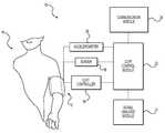
- FIG. 1illustrates a monitoring system, according to an exemplary embodiment.
- FIG. 2illustrates a pressure pulse applied by the monitoring system, according to an exemplary embodiment.
- FIG. 3illustrates a first flow chart, according to an exemplary embodiment.
- FIG. 4illustrates a second flow chart, according to another exemplary embodiment.
- the present disclosureprovides a suprasystolic measurement in a fast blood-pressure cycle. Both blood-pressure determination and suprasystolic measurement are generally completed in less time than a typical blood pressure assessment alone, such as, for example, about 25 seconds. The time is reduced in part because cuff re-inflation can be avoided.
- the present disclosurealso permits the use of real time data collected during inflation in a subsequent suprasystolic measurement. For example, an accurate suprasystolic pressure can be based on a systolic pressure determined during inflation. Further, if a suprasystolic measurement should occur, the duration of a suprasystolic measurement, or what sort of signal analysis should be performed during suprasystolic measurement can be determined during inflation.
- the combined blood-pressure determination and suprasystolic measurementcan provide dynamic information to a decision tree or algorithm to determine a particular hemodynamic parameter.
- a suprasystolic measurementmight be conducted on patients having certain physiological indicators, such as, weight, heart rate, or blood pressure.
- a patient's physiological indicatorsmay be determined during inflation. If one or more of these indicators fails to meet certain criteria, the suprasystolic measurement could be cancelled and the patient notified.
- various indicatorscould be tested during inflation to ensure suitable suprasystolic measurement.
- the present systemcan permit rapid analysis of hemodynamic data gathered from unloaded, partially loaded, or fully loaded vessels.
- the patient's vesselsBefore inflation, the patient's vessels are unloaded and blood flow is not restricted.
- a dynamic phasethe patient's vessels are progressively loaded, reducing blood flow.
- the patient's vesselsAt suprasystolic pressure, the patient's vessels are completely loaded or occluded, termed a “static phase.”
- Data gathered during these different conditionsmay be compared and contrasted to determine one or more hemodynamic parameters. For example, a beat-to-beat time during the dynamic phase, when the vessel is partially occluded, may be compared with a beat-to-beat time during the static phase, when the vessel is completely occluded. Such data comparison can provide an indication of irregular heart beat timing. Two or more separate conditions could also be used to attenuate signal noise using various de-noising algorithms.
- FIG. 1illustrates a system 10 , according to an exemplary embodiment of the present disclosure.
- System 10can be configured to monitor a patient, and in some embodiments, to determine a hemodynamic parameter of the patient.
- System 10can include a cuff 12 configured to at least to partially occlude the movement of blood through a vessel of patient 14 .
- cuff 12can be configured to completely completely occlude an artery of patient 14 .
- cuff 12may be adapted for placement on any suitable part of patient 14 , including, for example, a wrist, a finger, an upper thigh, or an ankle.
- one or more cuffs 12could be placed at different locations about patient 14 for use with system 10 .
- Cuff 12can include an inflatable device, wherein the pressure or volume within cuff 12 may be controlled by a cuff controller 16 operably associated with cuff 12 .
- Cuff controller 16can include a pump or similar device to inflate cuff 12 .
- cuff controller 16could supply cuff 12 with a fluid to increase the pressure or volume of cuff 12 .
- cuff controller 16could include mechanical, electrical, or chemical devices configured to control vessel occlusion of patient 14 via cuff 12 .
- cuff controller 16can generally maintain cuff 12 at about a target pressure. For example, once a target pressure has been determined, as explained in detail below, cuff controller 16 could control cuff 12 to provide patient 14 with a generally constant pressure. While the present disclosure refers to a target pressure, it should be understood that the actual pressure applied by cuff 12 may vary. As such, the pressure applied to patient 14 may generally remain within appropriate limits, such as, for example, with 2%, 5%, 10%, or 20% of the target pressure.
- System 10can further include a sensor 18 configured to receive a signal associated with patient 14 .
- sensor 18can be configured to receive a signal associated with an at least partially occluded vessel of patient 14 .
- Such an input signalcan arise from blood movement through a partially occluded vessel or from a signal associated with an occluded blood vessel.
- Sensor 18could sample multiple times at various intervals.
- sensor 18could provide an indication of blood vessel movement, such as, for example, oscillations arising from vascular expansion or contraction.
- sensor 18could be configured to detect a pressure or volume of cuff 12 that may vary periodically with the cyclic expansion and contraction of an artery of patient 14 .
- sensor 18could determine a blood pressure or other hemodynamic parameter associated with patient 14 —using an oscillometric method.
- sensor 18could detect a volume or a pressure associated with cuff 12 .
- sensor 18could include a pressure sensor and may be located within or about cuff 12 .
- System 10could further operate with a plurality of sensors 18 , and may include a high-resolution sensor or pneumatic sensor designed to operate in conjunction with cuff 12 .
- Sensor 18can further be configured to generate an output signal.
- the output signalmay be generated based on an input signal received from patient 14 .
- the output signalcan include a representation of an input signal associated with cuff 12 and/or patient 14 .
- Cuff 12 , cuff controller 16 , and sensor 18may be operably associated with a cuff control module 20 .
- cuff control module 20could include one or more processors configured to control one or more operations of cuff 12 , cuff controller 16 , or sensor 18 .
- cuff control module 20can control inflation of cuff 12 via control of cuff controller 16 .
- cuff control module 20can calculate a target pressure. This calculation may be based on an output signal from sensor 18 , as described above. Cuff control module 20 may also control inflation of cuff 12 , inflation of cuff 12 to the target pressure, or generally maintaining inflation of cuff 12 at about the target pressure.
- cuff control module 20could calculate a target pressure during inflation of cuff 12 . Such a calculation could take less than about 15 seconds. Cuff control module 20 could then generally maintain cuff 12 at about the target pressure for a defined time period, such as, for example, less than about 10 seconds. In other embodiments, the target pressure could be generally maintained for a defined number of cardiac cycles, such as, for example, six, eight, or ten cycles. Unlike current suprasystolic techniques, such cardiac cycle data may be available upon reaching the target pressure. This availability can reduce the need to ignore or discount one or more of the first several cardiac cycles from any suprasystolic measurement.
- Cuff compression using current techniquescan cause conscious or unconscious muscle movement, affecting signals obtained during the first few beats at a suprasystolic pressure. Such data may be unsuitable for parameter determination, thereby prolonging the static phase.
- a more gradual compression of a patient's limb or arteries up to a suprasystolic pressurecan reduce or eliminate the effects of these unwanted movements.
- system 10can optionally include a signal analysis module 22 , a communication module 24 , or an accelerometer 26 . These components may operate with one or more of the components of system 10 as described above.
- Signal analysis module 22may be configured to analyze one or more signals using one or more processors. Such analysis may be based on the output signal of sensor 18 .
- signal analysis module 22can include one or more filters configured to filter a signal associated with sensor 18 or cuff control module 20 . Such filters can include band-pass, high-pass, or low-pass filters.
- signal analysis module 22may determine a hemodynamic parameter.
- a hemodynamic parametercan include an indication of cardiac or vascular health, such as, for example, an indication of cardiac, circulatory, or vascular functionality.
- a hemodynamic parametercan include a heart rate, a blood pressure, a vessel compliance, an aortic index, an augmentation index, reflected wave ratio, or an indication of treatment.
- Blood pressurecan include systolic, diastolic, or mean atrial pressure.
- An indication of treatmentcan include a parameter reflecting the affect of a drug treatment, or one or more treatments of a disease state.
- a hemodynamic parametercan be determined based on a suprasystolic measurement. In other embodiments, a hemodynamic parameter can be determined based on a first set of data obtained during inflation of cuff 12 and a second set of data obtained during general maintenance of cuff 12 at about the target pressure, as explained below in detail.
- the first or second sets of datacan include various data associated with a signal waveform associated with patient 14 and/or cuff 12 , and may include amplitude, frequency, morphology, feature, or mathematically derived data.
- Datacan be derived from a derivative, integration, or frequency analysis, such as, for example, a fast-Fourier transform. Data may also be derived from various algorithms, including curve fitting, neural network, filtering, smoothing, or data processing.
- System 10can further include an accelerometer 26 to detect movement.
- Accelerometer 26can be configured to detect movement in one, two, or three dimensions.
- accelerometer 26could be used to detect movement of patient 14 or movement of the arm of patient 14 .
- a signal arising from accelerometer 26could be used to provide additional information to another module. For example, if movement of patient 14 is sufficient to interfere with sensor 18 , a signal from accelerometer 26 may be transmitted to cuff control module 20 to halt the pressure cycle. In-addition, a signal from accelerometer 26 may be transmitted to signal analysis module 22 to cancel or reset a calculation. Data obtained from sensor 18 could be combined with data from accelerometer 26 to determine if an irregular signal may be caused by a motion artifact. Various data from accelerometer 26 may be processed to provide additional data to determine one or more hemodynamic parameters.
- System 10can further include a communication module 24 configured to provide communication to patient 14 or one or more operators.
- communication module 24could include a display configured to display one or more hemodynamic parameters.
- communication modulecould include a transmitter configured to transmit data to a remote location.
- Communication module 24may further include audio output to communicate with patient 14 and/or an operator of system 10 .
- system 10may include various other components as required, such as, for example, a memory, a power source, and a user input.
- One or more components described hereinmay be combined or may be separate and operate with wireless or wired communication links.
- the various components of system 10could be integrated into a single processing unit or may operate as separate processors.
- one or more processorscan be configured to operate in conjunction with one or more software programs to provide the functionality of system 10 .
- FIG. 2shows a cuff pressure waveform 28 as applied to a patient over a period of time, according to an exemplary embodiment.
- waveform 28may be applied to patient 14 using system 10 as indicated in FIG. 1 .
- waveform 28can include a dynamic phase 30 and a static phase 32 .
- Dynamic phase 30can include a generally increasing pressure.
- dynamic phase 30can include a continuously increasing linear pressure curve.
- dynamic phase 30can include a step wise pressure increase, a curved pressure increase, an exponential pressure increase, a gradual, or a rapid pressure increase.
- Target pressure 34can be greater than systolic pressure or about equal to systolic pressure. In some embodiments, target pressure 34 can be about equal to a suprasystolic pressure.
- Static phase 32can include generally maintaining a cuff pressure at about target pressure 34 .
- a target pressurecan be determined during dynamic phase 30 and applied during static phase 32 .
- Target pressure 34can include a generally constant pressure.
- target pressure 34can fluctuate within a range of values. For example, target pressure 34 can include values within about ⁇ 2%, ⁇ 5%, ⁇ 10%, or ⁇ 20%.
- the duration of dynamic phase 30 and static phase 32should be less than about 60 seconds. In some embodiments, the duration of phases 30 , 32 can be less than about 45 seconds. In some embodiments, the duration of phases—; ⁇ 3.0, 32 can be less than about 30 seconds. In particular, the duration of dynamic phase 30 can be less than about 15 seconds and the duration of static phase 32 can be less than about 10 seconds.
- FIG. 2shows dynamic phase 20 and static phase 32 juxtaposed, in some embodiments these phases may be separated by one or more other phase of differing cuff pressure and/or duration.
- FIGS. 3 and 4illustrate flow charts of two exemplary embodiments according to the present disclosure.
- various modulescan include one or more hardware components and one or more software components that operate to control an operation of system 10 .
- Each step described belowcan be understood as corresponding to one or more computational instructions. These computational instructions can operate based on hardware and/or software components of system 10 , and may operate on one or more processors.
- FIG. 3includes a process 100 according to an exemplary embodiment of the present disclosure.
- Step 110labeled “Start,” may include one of more steps required to initiate an operation of system 10 .
- system 10may be turned on, a calibration protocol may be started, a cuff may be placed about a patient's arm, an operator may enter information to identify a patient, or information could be extracted from a database.
- various components of system 10may be calibrated or tested to ensure proper functioning. These operations could include a check of cuff integrity, if sufficient power is available, a calibration of one or more sensors, or confirmation of proper processor functioning.
- other informationmay be entered into system 10 , such as a patient identification, weight, gender, height, or other suitable data.
- Step 112cuff 12 may be inflated (Step 112 ). This step may be considered the start of dynamic phase 30 . In some embodiments, Step 112 could be initiated as part of Step 110 .
- cuff controller 16may operate to inflate cuff 12 .
- sensor 18may detect one or more signals. These signals may be analyzed by cuff control module 20 to determine if sufficient information has been obtained (Step 114 ).
- Sufficient informationcan refer to providing one or more algorithms with information sufficient to determine when cuff inflation should be terminated. For example, an algorithm could determine a target pressure for cuff inflation. In other embodiments, an algorithm could determine a time to stop cuff inflation.
- an algorithmmay use oscillometric pulse data obtained during dynamic phase 30 .
- the datamay be analyzed in real time until such a point that an algorithm deems the data sufficient for a reading determination.
- Such datacan relate to the maturity of the pulse envelope or the amount of envelope found during inflation.
- the collected pulse datacan be filtered and/or conditioned.
- a model curvecan be fit to the data.
- datacan be submitted to a trained network of mathematical routines. Such analysis can be used to determine a systolic pressure or a diastolic pressure.
- the SureBP algorithmcould be used to determine a systolic pressure.
- Such an algorithmis described in “Clinical evaluation of the Welch Allyn SureBP algorithm for automated blood pressure measurement,” by Bruce Alpert, which is hereby incorporated by reference in its entirety.
- Such an algorithmcan provide an accurate measure of systolic pressure during inflation, whereby the mean error is less than about 1 mmHg and the standard deviation of the mean error is less than about ⁇ 7 mmHg.
- such an algorithmcould provide a mean error of less than about 5 mmHg and a standard deviation of less than about ⁇ 5 mmHg.
- cuff inflation(Step 112 ) can continue until sufficient information has been obtained.
- One or more safety algorithmscould also be used to limit cuff inflation to a maximum pressure. For example, process 100 may terminate if cuff pressure reaches about 200 mmHg.
- a target pressuremay be determined (Step 116 ).
- the target pressuremay include determining a systolic pressure.
- a suprasystolic pressuremay then be determined based on the systolic pressure.
- a suprasystolic pressuremay be determined by adding about 10-40 mmHg to the value of the systolic pressure.
- the value of the target pressuremay be determined based on the suprasystolic pressure.
- the target pressuremay be set to the same value as the suprasystolic pressure.
- cuff inflationmay be continued to the target pressure (Step 118 ).
- dynamic phase 30can be considered complete and static phase 32 may begin.
- static phase 32cuff pressure can be maintained generally about the target pressure (Step 120 ). As previously described, such maintenance can include minor fluctuations about the target pressure.
- one or more hemodynamic parametersmay be determined (Step 122 ).
- the hemodynamic parametersmay be determined using suprasystolic analysis methods. For example, as described in U.S. Pat. No. 6,994,675 to Sharrock, large arterial vascular compliance may be determined using one of more signals obtained during static phase 32 (i.e. a suprasystolic phase). While Sharrock describes the use of a wideband acoustic transducer, signals from other pressure transducers can be used to analyze temporal or amplitude variations of signals obtained during the suprasystolic phase.
- process 100may end (Step 124 ). Termination of process 100 can include gradual or rapid cuff deflation, display of one or more hemodynamic parameters, or power shut-down.
- FIG. 4includes a process 200 according to another exemplary embodiment of the present disclosure.
- Process 200can include various steps similar to the steps described above for process 100 .
- Step 210labeled “Start,” may include one of more steps required to initiate an operation of system 10 , as previously described for Step 110 .
- Steps 212 , 214 , 216 , and 218can occur during dynamic phase 30 , as described above for Steps 112 , 114 , 116 , and 118 , respectively.
- Steps 220 and 224can occur during static phase 32 , as described above for Steps 120 and 124 , respectively.
- Process 200can include one or more additional steps during dynamic phase 30 .
- a first set of datacan be obtained during dynamic phase 30 (Step 215 ).
- Such datacan include information obtained from an oscillometric pulse.
- the source of the first set of datamay be different to the source providing data to determine the target pressure.
- Process 200can also include one or more additional steps during static phase 32 .
- a second set of datacan be obtained during static phase 32 (Step 221 ).
- first and second sets of datacan include any signal waveform data associated with patient 14 and/or cuff 12 , and may include amplitude, frequency, morphology, feature, or mathematically derived data.
- a hemodynamic parametercan be determined (Step 222 ).
- First and second data setscan be obtained and compared and contrasted to determine one or more parameters. For example, a beat-to-beat time during dynamic phase 30 can be compared to a beat-to-beat time during static phase 32 . Such a comparison can be used to check for irregular heart beat timing.
- Other parameterscan be determined based on comparing unloaded (i.e. dynamic phase 30 ) data with loaded (i.e. static phase 32 ) data. These two separate sample conditions can also be contrasted to determine one or more parameters using other methods known in the art.
- first and second data setsmay be used to remove common noise associated with both sets of data.
- a cleaner signalmay be used to more accurately or precisely determine a hemodynamic parameter.
- one or more parameters determined during static phase 32could be used to confirm any determinations based on data obtained during dynamic phase 30 .
- a second determination of systolic pressurecould be made based on a second set of data obtained during static phase 32 .
- the two values of systolic pressurecould be compared to ensure that both are within acceptable limits to confirm the accuracy of any calculated parameters. If outside acceptable limits, process 200 may be terminated (Step 224 ) and repeated if desired.
Landscapes
- Health & Medical Sciences (AREA)
- Life Sciences & Earth Sciences (AREA)
- Vascular Medicine (AREA)
- Cardiology (AREA)
- Biomedical Technology (AREA)
- Heart & Thoracic Surgery (AREA)
- Physiology (AREA)
- Biophysics (AREA)
- Pathology (AREA)
- Engineering & Computer Science (AREA)
- Ophthalmology & Optometry (AREA)
- Physics & Mathematics (AREA)
- Medical Informatics (AREA)
- Molecular Biology (AREA)
- Surgery (AREA)
- Animal Behavior & Ethology (AREA)
- General Health & Medical Sciences (AREA)
- Public Health (AREA)
- Veterinary Medicine (AREA)
- Measuring Pulse, Heart Rate, Blood Pressure Or Blood Flow (AREA)
Abstract
Description
Claims (21)
Priority Applications (1)
| Application Number | Priority Date | Filing Date | Title |
|---|---|---|---|
| US14/466,356US9833154B2 (en) | 2009-12-31 | 2014-08-22 | Suprasystolic measurement in a fast blood-pressure cycle |
Applications Claiming Priority (2)
| Application Number | Priority Date | Filing Date | Title |
|---|---|---|---|
| US12/650,984US8840561B2 (en) | 2009-12-31 | 2009-12-31 | Suprasystolic measurement in a fast blood-pressure cycle |
| US14/466,356US9833154B2 (en) | 2009-12-31 | 2014-08-22 | Suprasystolic measurement in a fast blood-pressure cycle |
Related Parent Applications (1)
| Application Number | Title | Priority Date | Filing Date |
|---|---|---|---|
| US12/650,984ContinuationUS8840561B2 (en) | 2009-12-31 | 2009-12-31 | Suprasystolic measurement in a fast blood-pressure cycle |
Publications (2)
| Publication Number | Publication Date |
|---|---|
| US20140364748A1 US20140364748A1 (en) | 2014-12-11 |
| US9833154B2true US9833154B2 (en) | 2017-12-05 |
Family
ID=43569484
Family Applications (2)
| Application Number | Title | Priority Date | Filing Date |
|---|---|---|---|
| US12/650,984Active2032-01-16US8840561B2 (en) | 2009-12-31 | 2009-12-31 | Suprasystolic measurement in a fast blood-pressure cycle |
| US14/466,356Active2031-09-27US9833154B2 (en) | 2009-12-31 | 2014-08-22 | Suprasystolic measurement in a fast blood-pressure cycle |
Family Applications Before (1)
| Application Number | Title | Priority Date | Filing Date |
|---|---|---|---|
| US12/650,984Active2032-01-16US8840561B2 (en) | 2009-12-31 | 2009-12-31 | Suprasystolic measurement in a fast blood-pressure cycle |
Country Status (5)
| Country | Link |
|---|---|
| US (2) | US8840561B2 (en) |
| EP (1) | EP2519146A1 (en) |
| CN (1) | CN102711599B (en) |
| AU (1) | AU2010337047B2 (en) |
| WO (1) | WO2011081955A1 (en) |
Families Citing this family (15)
| Publication number | Priority date | Publication date | Assignee | Title |
|---|---|---|---|---|
| US8840561B2 (en)* | 2009-12-31 | 2014-09-23 | Welch Allyn, Inc. | Suprasystolic measurement in a fast blood-pressure cycle |
| US9241642B2 (en) | 2012-02-16 | 2016-01-26 | Welch Allyn, Inc. | Systems and methods for monitoring a patient |
| US9301700B2 (en)* | 2012-09-27 | 2016-04-05 | Welch Allyn, Inc. | Configurable vital signs system |
| US11071467B2 (en) | 2013-08-08 | 2021-07-27 | Welch Allyn, Inc. | Hybrid patient monitoring system |
| US20160100805A1 (en) | 2014-10-10 | 2016-04-14 | Koninklijke Philips N.V. | Non-invasive blood pressure monitors and methods of operating the same |
| GB2537629B (en)* | 2015-04-21 | 2017-06-28 | Gen Electric | System and method for controlling a valve of a portable medical device |
| CZ306567B6 (en)* | 2016-01-07 | 2017-03-08 | České vysoké učenà technické v Praze | A method of precise automatic non-invasive sensing of a blood pulse wave and a device for performing this method |
| US11813044B2 (en) | 2016-06-14 | 2023-11-14 | Koninklijke Philips N.V. | Device and method for non-invasive assessment of maximum arterial compliance |
| US10772571B2 (en) | 2016-11-15 | 2020-09-15 | Welch Allyn, Inc. | Method and systems for correcting for arterial compliance in a blood pressure assessment |
| US11553848B2 (en) | 2017-09-29 | 2023-01-17 | Fitbit, Inc. | Devices and methods for controlling inflation rate in blood pressure measurements |
| JP6881288B2 (en)* | 2017-12-27 | 2021-06-02 | オムロンヘルスケア株式会社 | Biological information measuring devices, methods and programs |
| US11839451B2 (en) | 2020-09-23 | 2023-12-12 | Apple Inc. | Sensing structure for pulse-wave velocity measurement |
| US11397120B2 (en) | 2020-09-23 | 2022-07-26 | Apple Inc. | Interface pressure sensor system for electronic device |
| US11839450B2 (en)* | 2020-09-23 | 2023-12-12 | Apple Inc. | Pressure sensor module for wearable applanation tonometer |
| US12414698B2 (en)* | 2023-09-29 | 2025-09-16 | Qualcomm Incorporated | Devices and systems for controlling pressure during sensing |
Citations (15)
| Publication number | Priority date | Publication date | Assignee | Title |
|---|---|---|---|---|
| US5653241A (en) | 1994-08-23 | 1997-08-05 | Colin Corporation | Blood-pressure monitor apparatus |
| US6331159B1 (en) | 1995-11-01 | 2001-12-18 | Seiko Epson Corporation | Device for measuring physiological state |
| US6712768B2 (en) | 2002-01-10 | 2004-03-30 | Colin Corporation | Augmentation-index determining apparatus and arteriosclerosis inspecting apparatus |
| US20040077959A1 (en) | 2002-10-16 | 2004-04-22 | Colin Corporation | Vital-information obtaining apparatus |
| US6793628B2 (en) | 2002-04-17 | 2004-09-21 | Colin Medical Technology Corporation | Blood-pressure measuring apparatus having augmentation-index determining function |
| US6976966B2 (en) | 2002-12-20 | 2005-12-20 | Colin Medical Technology Corporation | Arteriosclerosis evaluating apparatus |
| US6994675B2 (en) | 2000-07-19 | 2006-02-07 | Sharrock Nigel E | Non-invasive measurement of suprasystolic signals |
| US20060200027A1 (en) | 2005-03-04 | 2006-09-07 | Medwave, Inc. | Articulated placement guide for sensor-based noninvasive blood pressure monitor |
| US20060224070A1 (en) | 2005-04-05 | 2006-10-05 | Sharrock Nigel E | System and method for non-invasive cardiovascular assessment from supra-systolic signals obtained with a wideband external pulse transducer in a blood pressure cuff |
| US7153269B1 (en)* | 2006-01-05 | 2006-12-26 | The General Electric Company | Method and system for estimation of blood pressure during cuff inflation |
| US20070185401A1 (en)* | 2006-02-06 | 2007-08-09 | Welch Allyn, Inc. | Blood pressure measurement |
| US7468037B2 (en) | 2004-02-18 | 2008-12-23 | Miklos Illyes | Apparatus and method for measuring hemodynamic parameters |
| US20090012411A1 (en) | 2007-06-20 | 2009-01-08 | Andrew Lowe | Method and apparatus for obtaining electronic oscillotory pressure signals from an inflatable blood pressure cuff |
| US20090287097A1 (en) | 2008-05-15 | 2009-11-19 | Andrew Lowe | Method for estimating a central pressure waveform obtained with a blood pressure cuff |
| US8840561B2 (en)* | 2009-12-31 | 2014-09-23 | Welch Allyn, Inc. | Suprasystolic measurement in a fast blood-pressure cycle |
Family Cites Families (1)
| Publication number | Priority date | Publication date | Assignee | Title |
|---|---|---|---|---|
| HU0400426D0 (en)* | 2004-02-18 | 2004-04-28 | Illyes Miklos Dr | Apparatus and method for measurement of dynamic characteristic of blood and for complex monitoring of circulatory system |
- 2009
- 2009-12-31USUS12/650,984patent/US8840561B2/enactiveActive
- 2010
- 2010-12-15WOPCT/US2010/060382patent/WO2011081955A1/enactiveApplication Filing
- 2010-12-15EPEP10795888Apatent/EP2519146A1/ennot_activeWithdrawn
- 2010-12-15CNCN201080059936.1Apatent/CN102711599B/ennot_activeExpired - Fee Related
- 2010-12-15AUAU2010337047Apatent/AU2010337047B2/ennot_activeCeased
- 2014
- 2014-08-22USUS14/466,356patent/US9833154B2/enactiveActive
Patent Citations (15)
| Publication number | Priority date | Publication date | Assignee | Title |
|---|---|---|---|---|
| US5653241A (en) | 1994-08-23 | 1997-08-05 | Colin Corporation | Blood-pressure monitor apparatus |
| US6331159B1 (en) | 1995-11-01 | 2001-12-18 | Seiko Epson Corporation | Device for measuring physiological state |
| US6994675B2 (en) | 2000-07-19 | 2006-02-07 | Sharrock Nigel E | Non-invasive measurement of suprasystolic signals |
| US6712768B2 (en) | 2002-01-10 | 2004-03-30 | Colin Corporation | Augmentation-index determining apparatus and arteriosclerosis inspecting apparatus |
| US6793628B2 (en) | 2002-04-17 | 2004-09-21 | Colin Medical Technology Corporation | Blood-pressure measuring apparatus having augmentation-index determining function |
| US20040077959A1 (en) | 2002-10-16 | 2004-04-22 | Colin Corporation | Vital-information obtaining apparatus |
| US6976966B2 (en) | 2002-12-20 | 2005-12-20 | Colin Medical Technology Corporation | Arteriosclerosis evaluating apparatus |
| US7468037B2 (en) | 2004-02-18 | 2008-12-23 | Miklos Illyes | Apparatus and method for measuring hemodynamic parameters |
| US20060200027A1 (en) | 2005-03-04 | 2006-09-07 | Medwave, Inc. | Articulated placement guide for sensor-based noninvasive blood pressure monitor |
| US20060224070A1 (en) | 2005-04-05 | 2006-10-05 | Sharrock Nigel E | System and method for non-invasive cardiovascular assessment from supra-systolic signals obtained with a wideband external pulse transducer in a blood pressure cuff |
| US7153269B1 (en)* | 2006-01-05 | 2006-12-26 | The General Electric Company | Method and system for estimation of blood pressure during cuff inflation |
| US20070185401A1 (en)* | 2006-02-06 | 2007-08-09 | Welch Allyn, Inc. | Blood pressure measurement |
| US20090012411A1 (en) | 2007-06-20 | 2009-01-08 | Andrew Lowe | Method and apparatus for obtaining electronic oscillotory pressure signals from an inflatable blood pressure cuff |
| US20090287097A1 (en) | 2008-05-15 | 2009-11-19 | Andrew Lowe | Method for estimating a central pressure waveform obtained with a blood pressure cuff |
| US8840561B2 (en)* | 2009-12-31 | 2014-09-23 | Welch Allyn, Inc. | Suprasystolic measurement in a fast blood-pressure cycle |
Non-Patent Citations (3)
| Title |
|---|
| Alpert, B.S. "Clinical evaluation of Welch Allyn SureBP algorithm for automated blood pressure measurement" Blood Pressure Monitoring 12(4):215-218 (2007). |
| International Patent Application No. PCT/US2010/060382: International Search Report and Written Opinion; dated Feb. 28, 2011. |
| McLaughlin, J. et al. Piezoelectric sensor determination of arterial pulse wave velocity: Physiol. Meas. 24:693-702 (2003). |
Also Published As
| Publication number | Publication date |
|---|---|
| AU2010337047A1 (en) | 2012-07-12 |
| CN102711599A (en) | 2012-10-03 |
| US20110160597A1 (en) | 2011-06-30 |
| WO2011081955A1 (en) | 2011-07-07 |
| US20140364748A1 (en) | 2014-12-11 |
| CN102711599B (en) | 2015-08-19 |
| US8840561B2 (en) | 2014-09-23 |
| AU2010337047B2 (en) | 2014-07-17 |
| EP2519146A1 (en) | 2012-11-07 |
Similar Documents
| Publication | Publication Date | Title |
|---|---|---|
| US9833154B2 (en) | Suprasystolic measurement in a fast blood-pressure cycle | |
| US9022942B2 (en) | Systems and methods for measuring arterial stiffness | |
| US8211030B2 (en) | NIBP target inflation pressure automation using derived SPO2 signals | |
| US11406272B2 (en) | Systems and methods for blood pressure measurement | |
| US10165984B2 (en) | Configurable vital signs system | |
| US8282567B2 (en) | Method and system for determination of pulse rate | |
| US9662051B2 (en) | Automated assessment of peripheral vascular condition | |
| US20120157791A1 (en) | Adaptive time domain filtering for improved blood pressure estimation | |
| US11154208B2 (en) | System and method of measurement of average blood pressure | |
| US6440080B1 (en) | Automatic oscillometric apparatus and method for measuring blood pressure | |
| US20050283083A1 (en) | Blood pressure measuring system and method | |
| WO2017199174A1 (en) | Non-invasive system and method for measuring blood pressure variability | |
| CN113226161A (en) | Control unit for deriving a measure of arterial compliance | |
| US20170196468A1 (en) | Method for an Accurate Automated Non-invasive Measurement of Blood Pressure Waveform and Apparatus to Carry Out the Same | |
| RU2800898C1 (en) | Device for measuring pulse wave velocity when measuring arterial pressure by oscillometric method with extended functions | |
| WO2023085278A1 (en) | Blood pressure estimation device and calibration method for blood pressure estimation device |
Legal Events
| Date | Code | Title | Description |
|---|---|---|---|
| AS | Assignment | Owner name:WELCH ALLYN, INC., NEW YORK Free format text:ASSIGNMENT OF ASSIGNORS INTEREST;ASSIGNORS:LANE, JOHN A.;QUINN, DAVID E.;KINSLEY, MATTHEW J.;AND OTHERS;REEL/FRAME:033641/0038 Effective date:20100113 | |
| AS | Assignment | Owner name:JPMORGAN CHASE BANK, N.A., AS COLLATERAL AGENT, ILLINOIS Free format text:SECURITY INTEREST;ASSIGNORS:ALLEN MEDICAL SYSTEMS, INC.;HILL-ROM SERVICES, INC.;ASPEN SURGICAL PRODUCTS, INC.;AND OTHERS;REEL/FRAME:036582/0123 Effective date:20150908 Owner name:JPMORGAN CHASE BANK, N.A., AS COLLATERAL AGENT, IL Free format text:SECURITY INTEREST;ASSIGNORS:ALLEN MEDICAL SYSTEMS, INC.;HILL-ROM SERVICES, INC.;ASPEN SURGICAL PRODUCTS, INC.;AND OTHERS;REEL/FRAME:036582/0123 Effective date:20150908 | |
| AS | Assignment | Owner name:JPMORGAN CHASE BANK, N.A., AS COLLATERAL AGENT, ILLINOIS Free format text:SECURITY AGREEMENT;ASSIGNORS:HILL-ROM SERVICES, INC.;ASPEN SURGICAL PRODUCTS, INC.;ALLEN MEDICAL SYSTEMS, INC.;AND OTHERS;REEL/FRAME:040145/0445 Effective date:20160921 Owner name:JPMORGAN CHASE BANK, N.A., AS COLLATERAL AGENT, IL Free format text:SECURITY AGREEMENT;ASSIGNORS:HILL-ROM SERVICES, INC.;ASPEN SURGICAL PRODUCTS, INC.;ALLEN MEDICAL SYSTEMS, INC.;AND OTHERS;REEL/FRAME:040145/0445 Effective date:20160921 | |
| STCF | Information on status: patent grant | Free format text:PATENTED CASE | |
| AS | Assignment | Owner name:ALLEN MEDICAL SYSTEMS, INC., ILLINOIS Free format text:RELEASE BY SECURED PARTY;ASSIGNOR:JPMORGAN CHASE BANK, N.A.;REEL/FRAME:050254/0513 Effective date:20190830 Owner name:HILL-ROM COMPANY, INC., ILLINOIS Free format text:RELEASE BY SECURED PARTY;ASSIGNOR:JPMORGAN CHASE BANK, N.A.;REEL/FRAME:050254/0513 Effective date:20190830 Owner name:HILL-ROM SERVICES, INC., ILLINOIS Free format text:RELEASE BY SECURED PARTY;ASSIGNOR:JPMORGAN CHASE BANK, N.A.;REEL/FRAME:050254/0513 Effective date:20190830 Owner name:ANODYNE MEDICAL DEVICE, INC., FLORIDA Free format text:RELEASE BY SECURED PARTY;ASSIGNOR:JPMORGAN CHASE BANK, N.A.;REEL/FRAME:050254/0513 Effective date:20190830 Owner name:VOALTE, INC., FLORIDA Free format text:RELEASE BY SECURED PARTY;ASSIGNOR:JPMORGAN CHASE BANK, N.A.;REEL/FRAME:050254/0513 Effective date:20190830 Owner name:WELCH ALLYN, INC., NEW YORK Free format text:RELEASE BY SECURED PARTY;ASSIGNOR:JPMORGAN CHASE BANK, N.A.;REEL/FRAME:050254/0513 Effective date:20190830 Owner name:HILL-ROM, INC., ILLINOIS Free format text:RELEASE BY SECURED PARTY;ASSIGNOR:JPMORGAN CHASE BANK, N.A.;REEL/FRAME:050254/0513 Effective date:20190830 Owner name:MORTARA INSTRUMENT SERVICES, INC., WISCONSIN Free format text:RELEASE BY SECURED PARTY;ASSIGNOR:JPMORGAN CHASE BANK, N.A.;REEL/FRAME:050254/0513 Effective date:20190830 Owner name:MORTARA INSTRUMENT, INC., WISCONSIN Free format text:RELEASE BY SECURED PARTY;ASSIGNOR:JPMORGAN CHASE BANK, N.A.;REEL/FRAME:050254/0513 Effective date:20190830 | |
| AS | Assignment | Owner name:JPMORGAN CHASE BANK, N.A., ILLINOIS Free format text:SECURITY AGREEMENT;ASSIGNORS:HILL-ROM HOLDINGS, INC.;HILL-ROM, INC.;HILL-ROM SERVICES, INC.;AND OTHERS;REEL/FRAME:050260/0644 Effective date:20190830 | |
| MAFP | Maintenance fee payment | Free format text:PAYMENT OF MAINTENANCE FEE, 4TH YEAR, LARGE ENTITY (ORIGINAL EVENT CODE: M1551); ENTITY STATUS OF PATENT OWNER: LARGE ENTITY Year of fee payment:4 | |
| AS | Assignment | Owner name:HILL-ROM HOLDINGS, INC., ILLINOIS Free format text:RELEASE OF SECURITY INTEREST AT REEL/FRAME 050260/0644;ASSIGNOR:JPMORGAN CHASE BANK, N.A.;REEL/FRAME:058517/0001 Effective date:20211213 Owner name:BARDY DIAGNOSTICS, INC., ILLINOIS Free format text:RELEASE OF SECURITY INTEREST AT REEL/FRAME 050260/0644;ASSIGNOR:JPMORGAN CHASE BANK, N.A.;REEL/FRAME:058517/0001 Effective date:20211213 Owner name:VOALTE, INC., FLORIDA Free format text:RELEASE OF SECURITY INTEREST AT REEL/FRAME 050260/0644;ASSIGNOR:JPMORGAN CHASE BANK, N.A.;REEL/FRAME:058517/0001 Effective date:20211213 Owner name:HILL-ROM, INC., ILLINOIS Free format text:RELEASE OF SECURITY INTEREST AT REEL/FRAME 050260/0644;ASSIGNOR:JPMORGAN CHASE BANK, N.A.;REEL/FRAME:058517/0001 Effective date:20211213 Owner name:WELCH ALLYN, INC., NEW YORK Free format text:RELEASE OF SECURITY INTEREST AT REEL/FRAME 050260/0644;ASSIGNOR:JPMORGAN CHASE BANK, N.A.;REEL/FRAME:058517/0001 Effective date:20211213 Owner name:ALLEN MEDICAL SYSTEMS, INC., ILLINOIS Free format text:RELEASE OF SECURITY INTEREST AT REEL/FRAME 050260/0644;ASSIGNOR:JPMORGAN CHASE BANK, N.A.;REEL/FRAME:058517/0001 Effective date:20211213 Owner name:HILL-ROM SERVICES, INC., ILLINOIS Free format text:RELEASE OF SECURITY INTEREST AT REEL/FRAME 050260/0644;ASSIGNOR:JPMORGAN CHASE BANK, N.A.;REEL/FRAME:058517/0001 Effective date:20211213 Owner name:BREATHE TECHNOLOGIES, INC., CALIFORNIA Free format text:RELEASE OF SECURITY INTEREST AT REEL/FRAME 050260/0644;ASSIGNOR:JPMORGAN CHASE BANK, N.A.;REEL/FRAME:058517/0001 Effective date:20211213 | |
| MAFP | Maintenance fee payment | Free format text:PAYMENT OF MAINTENANCE FEE, 8TH YEAR, LARGE ENTITY (ORIGINAL EVENT CODE: M1552); ENTITY STATUS OF PATENT OWNER: LARGE ENTITY Year of fee payment:8 |