US9832367B2 - Viewing device - Google Patents
Viewing deviceDownload PDFInfo
- Publication number
- US9832367B2 US9832367B2US14/144,748US201314144748AUS9832367B2US 9832367 B2US9832367 B2US 9832367B2US 201314144748 AUS201314144748 AUS 201314144748AUS 9832367 B2US9832367 B2US 9832367B2
- Authority
- US
- United States
- Prior art keywords
- frame
- screen
- optical sensor
- moving
- relative
- Prior art date
- Legal status (The legal status is an assumption and is not a legal conclusion. Google has not performed a legal analysis and makes no representation as to the accuracy of the status listed.)
- Active, expires
Links
Images


Classifications
- H04N5/23216—
- G—PHYSICS
- G06—COMPUTING OR CALCULATING; COUNTING
- G06F—ELECTRIC DIGITAL DATA PROCESSING
- G06F1/00—Details not covered by groups G06F3/00 - G06F13/00 and G06F21/00
- G06F1/16—Constructional details or arrangements
- G06F1/1613—Constructional details or arrangements for portable computers
- G06F1/1632—External expansion units, e.g. docking stations
- G—PHYSICS
- G09—EDUCATION; CRYPTOGRAPHY; DISPLAY; ADVERTISING; SEALS
- G09B—EDUCATIONAL OR DEMONSTRATION APPLIANCES; APPLIANCES FOR TEACHING, OR COMMUNICATING WITH, THE BLIND, DEAF OR MUTE; MODELS; PLANETARIA; GLOBES; MAPS; DIAGRAMS
- G09B21/00—Teaching, or communicating with, the blind, deaf or mute
- G09B21/001—Teaching or communicating with blind persons
- G09B21/008—Teaching or communicating with blind persons using visual presentation of the information for the partially sighted
- H—ELECTRICITY
- H04—ELECTRIC COMMUNICATION TECHNIQUE
- H04N—PICTORIAL COMMUNICATION, e.g. TELEVISION
- H04N23/00—Cameras or camera modules comprising electronic image sensors; Control thereof
- H04N23/50—Constructional details
- H—ELECTRICITY
- H04—ELECTRIC COMMUNICATION TECHNIQUE
- H04N—PICTORIAL COMMUNICATION, e.g. TELEVISION
- H04N23/00—Cameras or camera modules comprising electronic image sensors; Control thereof
- H04N23/60—Control of cameras or camera modules
- H04N23/62—Control of parameters via user interfaces
- H04N5/2251—
Definitions
- This inventionrelates to an apparatus to assist persons with impaired eyesight, low vision or other reading difficulties in reading or viewing an object.
- magnification and/or image enhancementIn assisting those with low vision or impaired eyesight to view an object or read text, it can be useful to employ magnification and/or image enhancement. This can be done through different types of devices ranging from a simple hand-held magnifying glass to a machine which employs a camera for capturing the object and a screen for displaying an electronic representation of the object.
- the electronic representationcan show the image magnified, with better contrast, different colors, inverted text and/or different brightness.
- the objectis placed on a support, in front of the camera.
- the objectis then manually moved with respect to the support and the camera so that the camera captures different parts of the object, and the screen subsequently displays the part being captured.
- the magnification levelcan typically be changed, resulting in less of the object being displayed on the screen when a large amount of magnification is desired.
- the objecthas to be moved around a lot in relation to the support and the camera in order to view the whole object.
- An apparatus to capture and display an image of an objectincludes a frame, at least one optical sensor for capturing the image of the object, means for moving the frame relative to a surface of the object in a first direction, and means for moving the optical sensor relative to the frame in a second direction.
- Additional and/or alternative embodimentsmay include a screen for displaying the image of the object; the optical sensor and the screen moving in tandem; the optical sensor being attached to a back surface of the screen or to a plate positioned behind the screen; the second direction being parallel to the screen; the screen being removable from the apparatus; the screen being integral with a tablet computer; the second direction being substantially perpendicular to the first direction; a lighting arrangement for lighting the object; a second optical sensor, which optionally can be rotated; a photovoltaic panel for powering the apparatus; the screen being a touch screen; controls connected to the frame and/or the screen for controlling the screen, movement of the apparatus and/or the optical sensor; and/or the apparatus having a weight in the range of about 700 grams to 10 kilograms.
- the means for moving the frame relative to a surface of the objectcan comprise any of one or more rollers, one or more skids, one or more slides, one or more treads or any combination of these or other devices which allow for movement relative to a surface of the object.
- any skids and/or slidescan have upwardly curved ends and/or a low friction surface.
- the meanscould optionally be motorized.
- the means for moving the optical sensor relative to the frame in a second directioncould include one or more slides, wheels, rails, bearings, linkages and any combination of these or other devices which allow for movement of the optical sensor relative to the frame.
- the meanscould optionally be motorized.
- the means for moving the frame across a surface of the object in a first directiondefines a plane, and the screen has a first position generally parallel to the plane, and a second position at an angle to the plane.
- the anglecan be 40 degrees to 60 degrees.
- the optical sensorcan be rotated or moveable relative to the frame. This can facilitate being able to capture an image of the object or being able to capture an image of an object at a distance or at another location, for example, in front of or to the side of the apparatus.
- a device for displaying an image of an objectcomprises a frame which can move across a surface of the object in a first direction; a body connected to the frame and able to move in relation to the frame in a second direction; and at least one optical sensor connected to the body.
- Additional and/or alternative embodimentsmay include a screen connected to the body for displaying images from the optical sensor; and/or the first direction being substantially perpendicular to the second direction.
- a method of forming a device for displaying an image of an objectcomprises forming a frame which can move across a surface of the object; and connecting a body with at least one optical sensor to the frame so that it can move in relation to the frame in a second direction.
- FIG. 1Ashows a perspective front view of an apparatus for viewing an object.
- FIG. 1Bshows a perspective view of the apparatus of FIG. 1A from a back side.
- FIG. 1Cshows a side view of the apparatus of FIG. 1A .
- FIG. 1Dshows a perspective view of the apparatus of FIG. 1A moving in a first direction.
- FIG. 1Eshows a perspective view of the apparatus of FIG. 1A moving in a second direction.
- FIG. 1Fshows a view of the apparatus of FIG. 1A in a closed position.
- FIG. 2Ashows a side view of an apparatus for viewing an object with multiple rollers for movement in a first direction.
- FIG. 2Bshows a side view of an apparatus for viewing an object with a caterpillar tread for movement in a first direction.
- FIG. 2Cshows a side view of an apparatus for viewing an object with a sliding foot for movement in a first direction.
- FIG. 2Dshows a side view of an apparatus for viewing an object with a single sliding foot and a roller for movement in a first direction.
- FIG. 3Ashows a back perspective view of an apparatus for viewing an object using wheels on profile for moving an optical sensor.
- FIG. 3Bshows a back perspective view of an apparatus for viewing an object using a plain bearing with low friction for moving an optical sensor.
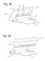
- FIG. 3Cshows a back perspective view of an apparatus for viewing an object using a ball bearing with carriage for moving an optical sensor.
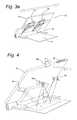
- FIGS. 3D-3Eshow a back perspective view of an apparatus for viewing an object using linkage with multiple rotation points for moving an optical sensor.
- FIG. 4shows an embodiment of an apparatus for viewing an object with two optical sensors and a lighting arrangement.
- FIG. 1Ashows a perspective view of apparatus 10 for viewing object 12 on surface 13
- FIG. 1Bshows a perspective view of apparatus 10 from a back side
- FIG. 1Cshows a side view of apparatus 10
- FIGS. 1D-1Eshow a perspective views of apparatus 10 moving in a first direction, and in a second direction, respectively.
- FIG. 1Fshows a view of apparatus 10 in a closed position.
- Apparatus 10includes frame 16 , connection means 17 and body 18 .
- Frame 16includes skids 20 , roller 22 and frame plate 24 .
- Body 18includes optical sensor 26 , screen 28 , controllers 30 , handles 32 and cover 34 .
- Connection means 17includes wheels 36 and rails 38 .
- Apparatus 10can be, for example, in the range of 700 grams to 10 kilograms.
- Screen 28can be integral to body 18 or can be detachable from body 18 .
- screen 28can be integral with a tablet computer and/or be a touch screen.
- Screen 28is large enough to display objects with a large amount of magnification, but small enough to be easily transportable, for example, seven inches (17.78 cm) to seventeen inches (43.18 cm).
- Apparatus 10can include a cover 34 , which can fold to protect screen 28 when not in use ( FIG. 1F ).
- Cover 34in some embodiments, could also act as a screen to filter light from optical sensor 26 when apparatus 10 is in use.
- Cover 34can also be detachable from apparatus 10 , and could be connected to apparatus 10 through magnetic means or other methods of connection.
- Optical sensor 26can be a camera connected to a back surface of body 18 to enable screen 28 to move with body 18 .
- optical sensor 26could be connected to a plate or other attachment which is connected to body 18 and/or screen 28 .
- optical sensor 26could be connected directly to screen 28 .
- Optical sensor 26could also be moveable and/or rotatable so that it could capture an object, for example, at a distance and not located in the position at which object 12 is shown in FIGS. 1B-1E or an object directly in front of device 10 .
- the object at a distancecould be, for example, a monitor, a blackboard or a whiteboard.
- Screen 28 , optical sensor 26 and/or other components of apparatus 10can be powered by batteries, for example located within body 18 , by a photovoltaic panel, by a plug-in power connection or by other means.
- Controllers 30are shown as buttons and a scroll wheel in the embodiment of FIGS. 1A-1F to control apparatus 10 , screen 28 and/or optical sensor 26 .
- Controllers 30are typically large, easy to use controllers 30 which can perform various functions, such as turning apparatus 10 on or off, adjusting the screen 28 display and/or adjusting placement of optical sensor 26 .
- controllers 30could include other types of controllers, including but not limited to a slide, switch, knob or other device for controlling the apparatus 10 , screen 28 , and/or optical sensor 26 .
- apparatus 10may have minimal or no other controllers 30 .
- Skids 20can have a low-friction surface, for example, Polyoxymethylene (“POM”), and can have curved ends for easier sliding movement around and/or over object 12 .
- Roller 22can be made of a material which has more friction, to allow it to roll across a surface and/or across object 12 .
- Skids 20 and frame plate 24connect to roller 22 , such that they can rotatably move with respect to each other.
- This rotatable connectionallows body 18 to go from a closed position in which back plate 24 sits against skids 20 and body 18 is substantially parallel with skids 20 and surface 13 (see FIG. 1F ) to an open position for capturing and displaying object 12 (see FIGS. 1A-1E ).
- frame plate 24In an open position, frame plate 24 is rotated to form an angle with surface 13 , placing optical sensor 26 at a location for capturing an image of object 12 .
- This anglecan be, for example, in the range of 30 degrees to 70 degrees, or another angle depending on apparatus 10 , object 12 , lighting and other conditions related to the capturing and displaying of object 12 .
- Frame 16connects to body 18 through wheels 36 , which are connected to frame plate 24 .
- Wheels 36engage rails 38 , which are connected to body 18 .
- the engagement of wheels 36 and rails 38allows for rolling or sliding movement between body 18 and frame 16 along rails 38 .
- Rails 38can have an end point to ensure that body 18 and frame 16 stay connected, and that the relative movement between body 18 and frame 16 does not make apparatus 10 unstable.
- Frame plate 24can cover connection means 17 to protect connection means 17 and/or hide from view for aesthetic purposes. While the embodiment of FIGS. 1A-1F show wheels 36 on frame 16 and rails 38 on body 18 , they could be switched around so that wheels are connected to body 18 and rails are connected to frame 16 .
- Apparatus 10acts to capture and display object 12 with a stable and compact frame by allowing movement in a first direction ( FIG. 1D ) and in a second direction ( FIG. 1E ).
- apparatus 10can be rotated open so that frame plate 24 sits at an angle from skids 20 and surface 13 , and optical sensor 26 is in position to capture images of object 12 , as shown in FIGS. 1A-1C .
- the usercan then use controllers 30 to turn on apparatus 10 and adjust settings as desired.
- Usermay then position optical sensor 26 so that it is directed at a point on object 12 where the user wishes to start viewing. For example if object 12 is a page of text, the desired starting point may be at the upper left hand corner.
- the usermay slide apparatus 10 over object 13 to the desired location.
- the usermay tilt apparatus 10 so that skids 20 are lifted from surface 13 , and only roller 22 touches surface 13 and/or object 12 .
- the usermay then roll apparatus 10 to the upper part of object 12 (See FIG. 1D ) across surface 13 .
- the usermay untilt apparatus 10 so that skids 20 lie on object 12 and/or surface 13 , stabilizing apparatus 10 .
- the tilting of the apparatus 10 and then rolling on roller 22can be especially useful when object 13 is a thick or uneven object, for example, a book.
- the usermay then move body 18 in a second direction by pushing or pulling body 18 and/or screen 28 , for example, using handles 32 (see FIG. 1E ). Wheels 36 will allow body 18 to move with respect to frame 16 in the direction it is pushed or pulled.
- optical sensor 26is fixed to body 18
- optical sensor 26is moved with body 18 , parallel and in tandem with screen 28 .
- Optical sensor 26is therefore positioned to capture the beginning of the text on object 12 so that screen 28 can display the text.
- the usercan move body 18 by pushing or pulling handles 32 to move optical sensor 26 to follow along with natural reading movements, from left to right.
- the userWhen the user needs to move down the page to read, he can once again slide apparatus 10 in that direction so that optical sensor 26 captures a portion of object 12 down the page.
- the usermay optionally tilt apparatus 10 and roll on roller 22 for this movement.
- the usermay then move body 18 in a second direction (across object 12 , substantially perpendicular to the first direction) again in the manner described above.
- Usermay use handles 32 for tilting, rolling, and/or sliding movement of apparatus 10 .
- apparatus 10By forming apparatus 10 with frame 16 that includes roller 22 and skids 20 for movement across object 12 in a first direction ( FIG. 1D ) and connection means 17 for movement of optical sensor 26 relative to frame 16 in a second direction ( FIG. 1E ), apparatus 10 can provide a large viewing screen 28 , while maintaining stability and portability.
- Roller 22 and skids 20allow for movement back and forth in relation to object 12
- wheels 36 on rails 38allow for side to side movement, allowing optical sensor 26 freedom of movement to capture object 12 .
- the ability to move in a first direction and in a second directionalso allows for a natural movement, for example, as the user is reading left to right, he can push on the handles 32 to move body 18 and screen 28 displaying object 12 left to right as well.
- apparatus 10can support a larger viewing screen 28 than past portable devices while still being able to fold to a small overall package for true portability.
- the larger viewing screenallows for use by those that require more magnification for viewing than past small screen devices could easily handle and provides the ability to have more information or text displayed before having to move apparatus 10 .
- Frame 16 and means to move apparatus 10 in two directionsallows for stable support of larger screen 28 , while eliminating the need for a user to be constantly lifting the viewing apparatus to move it when viewing an object or to move object in relation to the apparatus.
- the ability to move in two directions over object 12also allows a user to view object 12 through screen 28 with easy and natural movements, as the user moves body 18 and apparatus 10 in the direction the eyes would move on object 12 .
- the connections between frame 16 and body 18also allow for a stable device which the user is able to close when not in use, and could be easily transportable due to its size and compactness when closed.
- FIGS. 2A-2Dshow alternative embodiments of apparatus 10 , with different means for moving apparatus 10 , and particularly frame 16 in a first direction across object 12 . Similar parts are labeled similarly to FIGS. 1A-1F .
- FIG. 2Ashows a side view of apparatus 10 for viewing an object with multiple rollers 22 a , 22 b for movement across an object 12 .
- Rollers 22 a and 22 bcan be connected by rod 40 .
- Roller 22 bcan extend across the entire width of frame 16 , or could be one or two small rollers 22 b connected to frame 16 and/or roller 22 a .
- roller 22 acould be a number of smaller rollers connected to frame 16 .
- FIG. 2Bshows a side view of apparatus 10 with a caterpillar tread 42 for movement across an object 12 .
- Caterpillar tread 42can be motorized and includes track 44 , which wraps around wheels 46 to make an endless loop.
- Apparatus 10can have a single caterpillar tread 42 or multiple caterpillar treads 42 for moving apparatus 10 in a first direction.
- Caterpillar tread 42could also include more wheels 46 in other embodiments and could include controls on body 18 , frame 16 or elsewhere.
- apparatuscan be rolled on rollers 22 a , 22 b or moved on caterpillar tread 42 for movement in a first direction.
- FIG. 2Cshows a side view of apparatus 10 with a slide 48 for movement across an object 12 .
- Slide 48is angled at edges 49 to permit easier movement of apparatus 10 .
- Slide 48can be made of materials which permit easy sliding movements for moving apparatus 10 over object 12 and/or surface 13 , for example, POM.
- FIG. 2Dshows a side view of apparatus 10 for viewing an object 12 with a roller 22 and a single skid 20 .
- FIGS. 2C-2Dallow for easy movement of apparatus 10 in a first direction through tilting apparatus 10 and then sliding ( FIG. 2D ) or rolling ( FIG. 2E ) apparatus 10 . While a number of embodiments are shown as example means for moving frame 16 in a first direction, other means could also be used.
- FIGS. 3A-3Eshows alternative embodiments of apparatus 10 , with different means for moving apparatus 10 in a second direction, particularly in relation to moving body 18 relative to frame 16 . Similar parts are labeled similarly to FIGS. 1A-1F .
- FIG. 3Ashows a back perspective view of apparatus 10 with wheels 36 connected to body 18 and track 38 connected to frame 16 .
- FIG. 3Bshows a perspective view of apparatus 10 with a plain bearing 50 with low friction for sliding body 18 in relation to frame 16 .
- FIG. 3Cshows a perspective view of apparatus 10 with a ball bearing with carriage for moving body 18 in relation to frame 16 .
- FIGS. 3A-3Callow for relative movement between body 18 and frame 16 , allowing optical sensor 26 to move in a second direction.
- FIGS. 3D-3Eshow a perspective view of an embodiment of apparatus 10 which uses linkages 54 with multiple rotation points for moving body 18 relative to frame 16 .
- body 18is aligned with the center of frame 16
- linkagesallow for body 18 to move relative to frame 16 .
- While a number of embodimentsare shown as example means for moving optical sensor 26 in relation to frame 16 in a second direction, other means could be used, for example, other sliding, rolling or suspension means which permit relative movement.
- FIG. 4shows an embodiment of apparatus 10 for viewing object 12 with two optical sensors 26 a , 26 b and a lighting arrangement 56 .
- apparatus 10can move in a first direction and in a second direction for capturing object 12 and displaying on screen 28 .
- apparatusincludes a second optical sensor 26 b , which is positioned at the top of body 18 and is movable and able to be pointed at objects not on surface 13 .
- optical sensor 26 bcould point at object at a distance or an object directly in front of device 10 .
- These objects at a distancecould be, for example, a monitor, a blackboard or a whiteboard. This configuration can be especially useful when using apparatus 10 for performing hobbies which could take place in front of apparatus 10 .
- apparatus 10may only have optical sensor 26 b and/or optical sensor 26 a may be moveable with respect to body 18 .
- Apparatus 10also includes light sources 56 , for example, light emitting diodes (“LEDs”) powered by photovoltaic panel 58 .
- Light sources 56can be directed toward the same surface which optical sensor 26 a captures for display on screen 28 or could be rotatable and/or moveable to point in other directions.
- Light sources 56can illuminate object 12 , making the display on screen 28 more clear. Different numbers and/or arrangements of light sources 56 and/or optical sensors 26 a , 26 b could be used in other embodiments.
- apparatus 10allows for easy and stable viewing of object 12 through providing frame 16 with means for moving apparatus 10 across surface 13 and/or object 12 in a first direction and means for moving optical sensor 26 relative to frame 16 in a second direction. This allows for the user to move apparatus 10 and view object 12 with natural movements and allows for a larger screen 28 for display than past portable systems.
- Frame 16holds body stable for viewing and allows for compact folding and storage when not in use, and means for movement in first and second directions allow for a user to easily and naturally view all parts of an object on a surface with apparatus 10 .
- apparatus 10has been shown to have means which allow movement in a first direction in an “up and down the page” direction and means for moving in a second direction substantially perpendicular to that and “across the page,” these directions are for example purposes only, and the first and second directions could be oriented differently with respect to each other, object 12 and/or surface 13 .
- roller 22could be angled to promote diagonal movement.
Landscapes
- Engineering & Computer Science (AREA)
- Theoretical Computer Science (AREA)
- General Physics & Mathematics (AREA)
- Physics & Mathematics (AREA)
- Human Computer Interaction (AREA)
- Multimedia (AREA)
- Signal Processing (AREA)
- Audiology, Speech & Language Pathology (AREA)
- General Engineering & Computer Science (AREA)
- Health & Medical Sciences (AREA)
- Computer Hardware Design (AREA)
- General Health & Medical Sciences (AREA)
- Business, Economics & Management (AREA)
- Educational Administration (AREA)
- Educational Technology (AREA)
- Devices For Indicating Variable Information By Combining Individual Elements (AREA)
- Studio Devices (AREA)
- External Artificial Organs (AREA)
- Eye Examination Apparatus (AREA)
- Preparation Of Compounds By Using Micro-Organisms (AREA)
Abstract
Description
Claims (24)
Priority Applications (14)
| Application Number | Priority Date | Filing Date | Title |
|---|---|---|---|
| US14/144,748US9832367B2 (en) | 2013-12-31 | 2013-12-31 | Viewing device |
| SI201431708TSI2908208T1 (en) | 2013-12-31 | 2014-12-24 | Viewing device |
| RS20201371ARS61227B1 (en) | 2013-12-31 | 2014-12-24 | Viewing device |
| PL14200351TPL2908208T3 (en) | 2013-12-31 | 2014-12-24 | Viewing device |
| DK14200351.6TDK2908208T3 (en) | 2013-12-31 | 2014-12-24 | Display device |
| HUE14200351AHUE051716T2 (en) | 2013-12-31 | 2014-12-24 | Display device |
| LTEP14200351.6TLT2908208T (en) | 2013-12-31 | 2014-12-24 | Viewing device |
| ES14200351TES2830050T3 (en) | 2013-12-31 | 2014-12-24 | Display device |
| SM20200634TSMT202000634T1 (en) | 2013-12-31 | 2014-12-24 | Viewing device |
| PT142003516TPT2908208T (en) | 2013-12-31 | 2014-12-24 | Viewing device |
| EP14200351.6AEP2908208B1 (en) | 2013-12-31 | 2014-12-24 | Viewing device |
| US15/792,782US11115584B2 (en) | 2013-12-31 | 2017-10-25 | Viewing device |
| CY20201101089TCY1124065T1 (en) | 2013-12-31 | 2020-11-16 | DISPLAY ARRANGEMENT |
| HRP20201834TTHRP20201834T1 (en) | 2013-12-31 | 2020-11-17 | Viewing device |
Applications Claiming Priority (1)
| Application Number | Priority Date | Filing Date | Title |
|---|---|---|---|
| US14/144,748US9832367B2 (en) | 2013-12-31 | 2013-12-31 | Viewing device |
Related Child Applications (1)
| Application Number | Title | Priority Date | Filing Date |
|---|---|---|---|
| US15/792,782DivisionUS11115584B2 (en) | 2013-12-31 | 2017-10-25 | Viewing device |
Publications (2)
| Publication Number | Publication Date |
|---|---|
| US20150189160A1 US20150189160A1 (en) | 2015-07-02 |
| US9832367B2true US9832367B2 (en) | 2017-11-28 |
Family
ID=52338910
Family Applications (2)
| Application Number | Title | Priority Date | Filing Date |
|---|---|---|---|
| US14/144,748Active2034-10-05US9832367B2 (en) | 2013-12-31 | 2013-12-31 | Viewing device |
| US15/792,782ActiveUS11115584B2 (en) | 2013-12-31 | 2017-10-25 | Viewing device |
Family Applications After (1)
| Application Number | Title | Priority Date | Filing Date |
|---|---|---|---|
| US15/792,782ActiveUS11115584B2 (en) | 2013-12-31 | 2017-10-25 | Viewing device |
Country Status (13)
| Country | Link |
|---|---|
| US (2) | US9832367B2 (en) |
| EP (1) | EP2908208B1 (en) |
| CY (1) | CY1124065T1 (en) |
| DK (1) | DK2908208T3 (en) |
| ES (1) | ES2830050T3 (en) |
| HR (1) | HRP20201834T1 (en) |
| HU (1) | HUE051716T2 (en) |
| LT (1) | LT2908208T (en) |
| PL (1) | PL2908208T3 (en) |
| PT (1) | PT2908208T (en) |
| RS (1) | RS61227B1 (en) |
| SI (1) | SI2908208T1 (en) |
| SM (1) | SMT202000634T1 (en) |
Cited By (1)
| Publication number | Priority date | Publication date | Assignee | Title |
|---|---|---|---|---|
| US20180048806A1 (en)* | 2013-12-31 | 2018-02-15 | Optelec Holding B.V. | Viewing Device |
Families Citing this family (17)
| Publication number | Priority date | Publication date | Assignee | Title |
|---|---|---|---|---|
| CN105589606A (en)* | 2015-11-17 | 2016-05-18 | 苏州久腾光电科技有限公司 | Interactive electronic whiteboard with video communication function |
| US10485312B2 (en)* | 2016-08-30 | 2019-11-26 | Otter Products, Llc | Protective case system with stand |
| US10371312B2 (en)* | 2016-11-30 | 2019-08-06 | Microsoft Technology Licensing, Llc | Selectively rotatable feet for an apparatus |
| CN109428980B (en)* | 2017-08-23 | 2020-02-14 | 京东方科技集团股份有限公司 | Display device |
| EP3496072B1 (en)* | 2017-12-08 | 2024-12-04 | Optelec Holding B.V. | Viewing device for sight-impaired users |
| US10623043B2 (en) | 2018-01-23 | 2020-04-14 | Otter Products, Llc | Protective case for electronic device |
| US10750844B2 (en) | 2018-03-15 | 2020-08-25 | Otter Products, Llc | Protective case for use with device grip |
| US10694835B2 (en) | 2018-03-15 | 2020-06-30 | Otter Products, Llc | Protective case for use with device grip |
| CN108735157B (en)* | 2018-06-12 | 2020-04-10 | Oppo(重庆)智能科技有限公司 | Light sensor processing method and device, storage medium and electronic equipment |
| CN108877737A (en)* | 2018-06-12 | 2018-11-23 | 努比亚技术有限公司 | Screen adjustment method, mobile terminal and computer readable storage medium |
| US11256291B2 (en)* | 2018-08-03 | 2022-02-22 | Adam Lee Casey | Screened device stand |
| US11068030B2 (en) | 2018-12-19 | 2021-07-20 | Otter Products, Llc | Stand for use with electronic device |
| USD897329S1 (en) | 2019-07-02 | 2020-09-29 | Otter Products, Llc | Case for a smartphone |
| US11745670B2 (en) | 2020-05-06 | 2023-09-05 | Otter Products, Llc | Protective case system for use with electronic device |
| US11633025B2 (en) | 2020-06-26 | 2023-04-25 | Otter Products, Llc | Carrying case with stand |
| US12433391B2 (en) | 2021-03-29 | 2025-10-07 | Otter Products, Llc | Collapsible and extendable device grip |
| JP1727641S (en)* | 2021-07-13 | 2022-10-18 | camera |
Citations (54)
| Publication number | Priority date | Publication date | Assignee | Title |
|---|---|---|---|---|
| JPH11355633A (en)* | 1998-06-04 | 1999-12-24 | Matsushita Electric Ind Co Ltd | Magnifying reader |
| US6259006B1 (en) | 1996-08-30 | 2001-07-10 | Raoul Parienti | Portable foldable electronic piano |
| US6353529B1 (en)* | 1998-11-12 | 2002-03-05 | Thomas Cies | Z-configuration structure for computers, scanners, and communications and video devices |
| JP2003235037A (en)* | 2002-02-12 | 2003-08-22 | Canon Inc | Portable equipment with photographic optical means |
| JP2003235038A (en)* | 2002-02-12 | 2003-08-22 | Canon Inc | Portable equipment with photographic optical means |
| US20030222848A1 (en)* | 2002-05-31 | 2003-12-04 | Solomon Mark C. | System and method of switching viewing orientations of a display |
| GB2403370A (en)* | 2003-06-17 | 2004-12-29 | Ash Technologies Res Ltd | A handheld viewing device |
| US20060234784A1 (en)* | 2004-12-21 | 2006-10-19 | Silviu Reinhorn | Collapsible portable display |
| US20060232578A1 (en)* | 2004-12-21 | 2006-10-19 | Silviu Reinhorn | Collapsible portable display |
| US20070035917A1 (en)* | 2005-08-09 | 2007-02-15 | Apple Computer, Inc. | Methods and apparatuses for docking a portable electronic device that has a planar like configuration and that operates in multiple orientations |
| WO2007121605A1 (en) | 2006-04-21 | 2007-11-01 | Dreamcom Corporation | Laptop computer |
| EP2018030A1 (en) | 2007-07-18 | 2009-01-21 | Blue Bee Limited | A docking station and a kit for a personal electronic device |
| US7490887B2 (en)* | 2005-06-16 | 2009-02-17 | Vitito Christopher J | Vehicle entertainment system |
| US7492579B2 (en)* | 2003-09-12 | 2009-02-17 | Hewlett-Packard Development Company, L.P. | Computer with adjustable display |
| US20090059038A1 (en)* | 2004-04-13 | 2009-03-05 | Seakins Paul J | Image magnifier for the visually impaired |
| US20090091649A1 (en)* | 2007-10-05 | 2009-04-09 | Anderson Leroy E | Electronic document viewer |
| WO2009128700A1 (en) | 2008-04-14 | 2009-10-22 | Optelec Development B.V. | Braille display |
| US20100073515A1 (en)* | 2008-09-22 | 2010-03-25 | Todd Conard | Systems and methods for imaging objects |
| US20100079356A1 (en)* | 2008-09-30 | 2010-04-01 | Apple Inc. | Head-mounted display apparatus for retaining a portable electronic device with display |
| WO2010060168A2 (en)* | 2008-11-25 | 2010-06-03 | Bonavision Auxílios Ópticos Ltda | Support apparatus for optical materials to assist the viewing, process to assist the viewing of objects, optical material with adjustable focus |
| US7983035B1 (en)* | 2010-09-07 | 2011-07-19 | Shao-Chieh Ting | Sliding table of a tablet personal computer |
| US20110259788A1 (en)* | 2010-04-22 | 2011-10-27 | Atoz Design Labs Co., Limited | Tablet pc cover with stowable input device |
| US8115831B2 (en)* | 2008-08-04 | 2012-02-14 | Freedom Scientific, Inc. | Portable multi position magnifier camera |
| US20120037285A1 (en)* | 2010-08-10 | 2012-02-16 | Incase Designs Corp. | Case for Electronic Tablet |
| US20120083314A1 (en)* | 2010-09-30 | 2012-04-05 | Ng Hock M | Multimedia Telecommunication Apparatus With Motion Tracking |
| DE102010042612A1 (en)* | 2010-10-19 | 2012-04-19 | Philipp Stroh | Holder for mobile communication device has receiving portion in which mobile communication device is arranged such that optical sensor of device detects object within focal length of refractive optical element |
| US20120106047A1 (en)* | 2010-10-28 | 2012-05-03 | Chao-Ming Chu | Tablet electronic device |
| US20120173018A1 (en)* | 2010-12-30 | 2012-07-05 | Irobot Corporation | Mobile Human Interface Robot |
| US20120194738A1 (en)* | 2011-01-26 | 2012-08-02 | Yongjing Wang | Dual mode projection docking device for portable electronic devices |
| US20120268891A1 (en)* | 2011-04-14 | 2012-10-25 | Fabio Cencioni | Case for a tablet-type electronic device, in particular a tablet computer |
| US20120293683A1 (en)* | 2010-01-26 | 2012-11-22 | Kyocera Corporation | Portable electronic device |
| US20120307026A1 (en)* | 2008-08-04 | 2012-12-06 | Freedom Scientific, Inc. | Multiposition Handheld Electronic Magnifier |
| US20130068916A1 (en)* | 2011-03-16 | 2013-03-21 | Ergotron, Inc. | Reclining stand system and method |
| US20130076993A1 (en)* | 2011-09-28 | 2013-03-28 | Stephen Wyllie | Moving display system |
| US20130088830A1 (en)* | 2011-10-11 | 2013-04-11 | Hui Leng Lim | Dual-orientation docking apparatus |
| US20130109371A1 (en)* | 2010-04-26 | 2013-05-02 | Hu-Do Ltd. | Computing device operable to work in conjunction with a companion electronic device |
| US20130107138A1 (en)* | 2011-10-28 | 2013-05-02 | Kabushiki Kaisha Toshiba | Television receiver and electronic apparatus |
| US20130107136A1 (en)* | 2011-10-28 | 2013-05-02 | Kabushiki Kaisha Toshiba | Stand and electronic equipment |
| US20130163197A1 (en)* | 2011-12-23 | 2013-06-27 | Qwest Communications International Inc. | Integrated Magnetic Tablet Stand |
| US20130208161A1 (en)* | 2012-02-15 | 2013-08-15 | Hims International Corporation | Portable Magnifying Apparatus Having Multi Angular Positioned Handle |
| WO2013135299A1 (en) | 2012-03-15 | 2013-09-19 | Cherradi El Fadili Ibrahim Farid | Extending the free fingers typing technology and introducing the finger taps language technology |
| US20130248676A1 (en)* | 2012-03-21 | 2013-09-26 | Inventec Corporation | Supporting component |
| US20130249821A1 (en) | 2011-09-27 | 2013-09-26 | The Board of Trustees of the Leland Stanford, Junior, University | Method and System for Virtual Keyboard |
| US20130256497A1 (en)* | 2012-03-29 | 2013-10-03 | Rambod Radmard | Apparatus to support portable electronic devices and other devices or objects |
| US20130275643A1 (en)* | 2011-08-31 | 2013-10-17 | Z124 | Mobile device that docks with multiple types of docks |
| US20140015448A1 (en)* | 2011-12-29 | 2014-01-16 | Jered Wikander | Electronic device having a motion detector |
| US20140078389A1 (en)* | 2012-09-20 | 2014-03-20 | Nicholas G. L. Merz | Camera Accessory for Angled Camera Viewing |
| US8690576B2 (en) | 2004-01-30 | 2014-04-08 | Freedom Scientific, Inc. | Braille display device and method of constructing same |
| US20140146446A1 (en)* | 2012-11-27 | 2014-05-29 | Kabushiki Kaisha Toshiba | Electronic Device |
| US20140181347A1 (en)* | 2012-12-21 | 2014-06-26 | Technologies Humanware Inc. | Docking assembly for a handheld device |
| US20140176767A1 (en)* | 2012-12-21 | 2014-06-26 | Technologies Humanware Inc. | Handheld magnification device with a two-camera module |
| US20140247548A1 (en)* | 2012-04-20 | 2014-09-04 | Sameer Sharma | Hybrid computing device, apparatus and system |
| US20140263939A1 (en)* | 2013-03-16 | 2014-09-18 | James A. Rinner | Phone camera tablet bipod support system |
| US20140347812A1 (en)* | 2013-05-23 | 2014-11-27 | Wistron Corporation | Portable electronic device |
Family Cites Families (17)
| Publication number | Priority date | Publication date | Assignee | Title |
|---|---|---|---|---|
| US6282082B1 (en)* | 1998-07-31 | 2001-08-28 | Qubit, Llc | Case for a modular tablet computer system |
| US6731326B1 (en)* | 1999-04-06 | 2004-05-04 | Innoventions, Inc. | Low vision panning and zooming device |
| TW562182U (en)* | 2003-01-30 | 2003-11-11 | Micro Star Int Co Ltd | Tablet computer accommodation device with a supporting design |
| US7825949B2 (en)* | 2005-03-09 | 2010-11-02 | Trulaske James A | Closed circuit video magnification system |
| TWI259716B (en)* | 2005-04-29 | 2006-08-01 | Benq Corp | Display module with a support structure |
| US8854441B2 (en)* | 2006-02-10 | 2014-10-07 | Freedom Scientific, Inc. | Electronic magnification device |
| US8854442B2 (en)* | 2006-02-10 | 2014-10-07 | Freedom Scientific, Inc. | Retainer for electronic magnification device |
| US20090095854A1 (en)* | 2007-09-06 | 2009-04-16 | Paul Wilbur Forbes | Formable Stand System |
| US8610965B2 (en)* | 2007-11-26 | 2013-12-17 | Optelec Development B.V. | Reproduction device, assembly of a reproductive device and an indication body, and a method for reproducing an image portion |
| US8378625B2 (en)* | 2010-02-03 | 2013-02-19 | James Robert Gourley | Mobile electronic device AC charger mount |
| US20120019113A1 (en)* | 2010-07-26 | 2012-01-26 | Hale Eric C | Device Case and Mounting Apparatus With Flexible Support Legs |
| WO2013123599A1 (en) | 2012-02-24 | 2013-08-29 | Research In Motion Limited | Handheld device with notification message viewing |
| US9995432B1 (en)* | 2012-10-03 | 2018-06-12 | Dimitri Girault | Portable computing tablet holster |
| US20140117193A1 (en)* | 2012-10-29 | 2014-05-01 | Alison Wong | Stand for a portable electronic device |
| CN104081675A (en)* | 2013-01-18 | 2014-10-01 | 科鲁索泰科有限公司 | Holder for mobile terminal |
| US9143180B2 (en)* | 2013-12-27 | 2015-09-22 | Cheng-Hsien Shen | Cell phone charger holder |
| US9832367B2 (en)* | 2013-12-31 | 2017-11-28 | Optelec Holding B.V. | Viewing device |
- 2013
- 2013-12-31USUS14/144,748patent/US9832367B2/enactiveActive
- 2014
- 2014-12-24ESES14200351Tpatent/ES2830050T3/enactiveActive
- 2014-12-24SMSM20200634Tpatent/SMT202000634T1/enunknown
- 2014-12-24PLPL14200351Tpatent/PL2908208T3/enunknown
- 2014-12-24PTPT142003516Tpatent/PT2908208T/enunknown
- 2014-12-24LTLTEP14200351.6Tpatent/LT2908208T/enunknown
- 2014-12-24EPEP14200351.6Apatent/EP2908208B1/enactiveActive
- 2014-12-24HUHUE14200351Apatent/HUE051716T2/enunknown
- 2014-12-24DKDK14200351.6Tpatent/DK2908208T3/enactive
- 2014-12-24RSRS20201371Apatent/RS61227B1/enunknown
- 2014-12-24SISI201431708Tpatent/SI2908208T1/enunknown
- 2017
- 2017-10-25USUS15/792,782patent/US11115584B2/enactiveActive
- 2020
- 2020-11-16CYCY20201101089Tpatent/CY1124065T1/enunknown
- 2020-11-17HRHRP20201834TTpatent/HRP20201834T1/enunknown
Patent Citations (59)
| Publication number | Priority date | Publication date | Assignee | Title |
|---|---|---|---|---|
| US6259006B1 (en) | 1996-08-30 | 2001-07-10 | Raoul Parienti | Portable foldable electronic piano |
| JPH11355633A (en)* | 1998-06-04 | 1999-12-24 | Matsushita Electric Ind Co Ltd | Magnifying reader |
| US6353529B1 (en)* | 1998-11-12 | 2002-03-05 | Thomas Cies | Z-configuration structure for computers, scanners, and communications and video devices |
| JP2003235037A (en)* | 2002-02-12 | 2003-08-22 | Canon Inc | Portable equipment with photographic optical means |
| JP2003235038A (en)* | 2002-02-12 | 2003-08-22 | Canon Inc | Portable equipment with photographic optical means |
| US20030222848A1 (en)* | 2002-05-31 | 2003-12-04 | Solomon Mark C. | System and method of switching viewing orientations of a display |
| GB2403370A (en)* | 2003-06-17 | 2004-12-29 | Ash Technologies Res Ltd | A handheld viewing device |
| US7492579B2 (en)* | 2003-09-12 | 2009-02-17 | Hewlett-Packard Development Company, L.P. | Computer with adjustable display |
| US8690576B2 (en) | 2004-01-30 | 2014-04-08 | Freedom Scientific, Inc. | Braille display device and method of constructing same |
| US20090059038A1 (en)* | 2004-04-13 | 2009-03-05 | Seakins Paul J | Image magnifier for the visually impaired |
| US20060232578A1 (en)* | 2004-12-21 | 2006-10-19 | Silviu Reinhorn | Collapsible portable display |
| US20060234784A1 (en)* | 2004-12-21 | 2006-10-19 | Silviu Reinhorn | Collapsible portable display |
| US7490887B2 (en)* | 2005-06-16 | 2009-02-17 | Vitito Christopher J | Vehicle entertainment system |
| US20070035917A1 (en)* | 2005-08-09 | 2007-02-15 | Apple Computer, Inc. | Methods and apparatuses for docking a portable electronic device that has a planar like configuration and that operates in multiple orientations |
| WO2007121605A1 (en) | 2006-04-21 | 2007-11-01 | Dreamcom Corporation | Laptop computer |
| US20100053876A1 (en)* | 2006-04-21 | 2010-03-04 | Dreamcom Corporation | Laptop computer |
| EP2018030A1 (en) | 2007-07-18 | 2009-01-21 | Blue Bee Limited | A docking station and a kit for a personal electronic device |
| US20100195279A1 (en)* | 2007-07-18 | 2010-08-05 | Blue Bee Limited | Docking station and kit for a personal electronic device |
| US20090091649A1 (en)* | 2007-10-05 | 2009-04-09 | Anderson Leroy E | Electronic document viewer |
| WO2009128700A1 (en) | 2008-04-14 | 2009-10-22 | Optelec Development B.V. | Braille display |
| US8115831B2 (en)* | 2008-08-04 | 2012-02-14 | Freedom Scientific, Inc. | Portable multi position magnifier camera |
| US20120307026A1 (en)* | 2008-08-04 | 2012-12-06 | Freedom Scientific, Inc. | Multiposition Handheld Electronic Magnifier |
| US20100073515A1 (en)* | 2008-09-22 | 2010-03-25 | Todd Conard | Systems and methods for imaging objects |
| US20100079356A1 (en)* | 2008-09-30 | 2010-04-01 | Apple Inc. | Head-mounted display apparatus for retaining a portable electronic device with display |
| WO2010060168A2 (en)* | 2008-11-25 | 2010-06-03 | Bonavision Auxílios Ópticos Ltda | Support apparatus for optical materials to assist the viewing, process to assist the viewing of objects, optical material with adjustable focus |
| US20120293683A1 (en)* | 2010-01-26 | 2012-11-22 | Kyocera Corporation | Portable electronic device |
| US20110259788A1 (en)* | 2010-04-22 | 2011-10-27 | Atoz Design Labs Co., Limited | Tablet pc cover with stowable input device |
| US8201687B2 (en)* | 2010-04-22 | 2012-06-19 | Atoz Design Labs Co., Limited | Tablet PC cover with stowable input device |
| US20130109371A1 (en)* | 2010-04-26 | 2013-05-02 | Hu-Do Ltd. | Computing device operable to work in conjunction with a companion electronic device |
| US20120037285A1 (en)* | 2010-08-10 | 2012-02-16 | Incase Designs Corp. | Case for Electronic Tablet |
| US7983035B1 (en)* | 2010-09-07 | 2011-07-19 | Shao-Chieh Ting | Sliding table of a tablet personal computer |
| US20120083314A1 (en)* | 2010-09-30 | 2012-04-05 | Ng Hock M | Multimedia Telecommunication Apparatus With Motion Tracking |
| DE102010042612A1 (en)* | 2010-10-19 | 2012-04-19 | Philipp Stroh | Holder for mobile communication device has receiving portion in which mobile communication device is arranged such that optical sensor of device detects object within focal length of refractive optical element |
| US20120106047A1 (en)* | 2010-10-28 | 2012-05-03 | Chao-Ming Chu | Tablet electronic device |
| US20120173018A1 (en)* | 2010-12-30 | 2012-07-05 | Irobot Corporation | Mobile Human Interface Robot |
| US20120194738A1 (en)* | 2011-01-26 | 2012-08-02 | Yongjing Wang | Dual mode projection docking device for portable electronic devices |
| US20130068916A1 (en)* | 2011-03-16 | 2013-03-21 | Ergotron, Inc. | Reclining stand system and method |
| US20120268891A1 (en)* | 2011-04-14 | 2012-10-25 | Fabio Cencioni | Case for a tablet-type electronic device, in particular a tablet computer |
| US20130275643A1 (en)* | 2011-08-31 | 2013-10-17 | Z124 | Mobile device that docks with multiple types of docks |
| US20130249821A1 (en) | 2011-09-27 | 2013-09-26 | The Board of Trustees of the Leland Stanford, Junior, University | Method and System for Virtual Keyboard |
| US20130076993A1 (en)* | 2011-09-28 | 2013-03-28 | Stephen Wyllie | Moving display system |
| US20130088830A1 (en)* | 2011-10-11 | 2013-04-11 | Hui Leng Lim | Dual-orientation docking apparatus |
| US8619416B2 (en)* | 2011-10-11 | 2013-12-31 | Hewlett-Packard Development Company, L.P. | Dual-orientation docking apparatus |
| US20130107136A1 (en)* | 2011-10-28 | 2013-05-02 | Kabushiki Kaisha Toshiba | Stand and electronic equipment |
| US20130107138A1 (en)* | 2011-10-28 | 2013-05-02 | Kabushiki Kaisha Toshiba | Television receiver and electronic apparatus |
| US20130163197A1 (en)* | 2011-12-23 | 2013-06-27 | Qwest Communications International Inc. | Integrated Magnetic Tablet Stand |
| US20140015448A1 (en)* | 2011-12-29 | 2014-01-16 | Jered Wikander | Electronic device having a motion detector |
| US20130208161A1 (en)* | 2012-02-15 | 2013-08-15 | Hims International Corporation | Portable Magnifying Apparatus Having Multi Angular Positioned Handle |
| US8743278B2 (en)* | 2012-02-15 | 2014-06-03 | Hims International Corporation | Portable magnifying apparatus having multi angular positioned handle |
| WO2013135299A1 (en) | 2012-03-15 | 2013-09-19 | Cherradi El Fadili Ibrahim Farid | Extending the free fingers typing technology and introducing the finger taps language technology |
| US20130248676A1 (en)* | 2012-03-21 | 2013-09-26 | Inventec Corporation | Supporting component |
| US20130256497A1 (en)* | 2012-03-29 | 2013-10-03 | Rambod Radmard | Apparatus to support portable electronic devices and other devices or objects |
| US20140247548A1 (en)* | 2012-04-20 | 2014-09-04 | Sameer Sharma | Hybrid computing device, apparatus and system |
| US20140078389A1 (en)* | 2012-09-20 | 2014-03-20 | Nicholas G. L. Merz | Camera Accessory for Angled Camera Viewing |
| US20140146446A1 (en)* | 2012-11-27 | 2014-05-29 | Kabushiki Kaisha Toshiba | Electronic Device |
| US20140181347A1 (en)* | 2012-12-21 | 2014-06-26 | Technologies Humanware Inc. | Docking assembly for a handheld device |
| US20140176767A1 (en)* | 2012-12-21 | 2014-06-26 | Technologies Humanware Inc. | Handheld magnification device with a two-camera module |
| US20140263939A1 (en)* | 2013-03-16 | 2014-09-18 | James A. Rinner | Phone camera tablet bipod support system |
| US20140347812A1 (en)* | 2013-05-23 | 2014-11-27 | Wistron Corporation | Portable electronic device |
Non-Patent Citations (3)
| Title |
|---|
| EPO Search Report and Written Opinion for EP Application No. 14200351 (Published as EP2908208), dated Oct. 12, 2015.* |
| Extended European Search Report for related European Application No. 15171383.1 dated Nov. 2, 2015 (8 pages). |
| Jagtman, S. "A new touch in Braille display design: The design of a next generation Braille display", TU Delft Institutional Repository, Aug. 28, 2013. Retrieved from the Internet on Oct. 20, 2015, URL:<http://repository.tudelft.nl/view/ir/uuid%3Abf0a67e1-c74a-4291-917f-c686f7501a9b> (3 pages). |
Cited By (2)
| Publication number | Priority date | Publication date | Assignee | Title |
|---|---|---|---|---|
| US20180048806A1 (en)* | 2013-12-31 | 2018-02-15 | Optelec Holding B.V. | Viewing Device |
| US11115584B2 (en)* | 2013-12-31 | 2021-09-07 | Optelec Holding B.V. | Viewing device |
Also Published As
| Publication number | Publication date |
|---|---|
| SMT202000634T1 (en) | 2021-01-05 |
| US20150189160A1 (en) | 2015-07-02 |
| HRP20201834T1 (en) | 2021-04-02 |
| LT2908208T (en) | 2021-01-11 |
| PT2908208T (en) | 2020-11-16 |
| RS61227B1 (en) | 2021-01-29 |
| EP2908208A3 (en) | 2015-11-18 |
| US20180048806A1 (en) | 2018-02-15 |
| EP2908208A2 (en) | 2015-08-19 |
| SI2908208T1 (en) | 2021-07-30 |
| EP2908208B1 (en) | 2020-08-19 |
| DK2908208T3 (en) | 2020-11-16 |
| HUE051716T2 (en) | 2021-03-29 |
| US11115584B2 (en) | 2021-09-07 |
| ES2830050T3 (en) | 2021-06-02 |
| PL2908208T3 (en) | 2021-06-14 |
| CY1124065T1 (en) | 2022-03-24 |
Similar Documents
| Publication | Publication Date | Title |
|---|---|---|
| US11115584B2 (en) | Viewing device | |
| JP6126017B2 (en) | Holding device for electronic magnifying device | |
| US9961337B2 (en) | Flexible display device and computer with sensors and control approaches | |
| CN106142921B (en) | Multifunction electronic blackboard | |
| ES2796798T3 (en) | Auxiliary cart | |
| CN102697288B (en) | Multifunctional desk | |
| TWI531888B (en) | Electronic device having a motion detector | |
| TWM375485U (en) | Portable microscope | |
| US20090262493A1 (en) | Digital picture frame | |
| US9552017B2 (en) | Electronic device | |
| KR20160067588A (en) | Apparatus for both table and digital information display | |
| US9144330B2 (en) | Display device | |
| CN206049131U (en) | Multifunction electronic blackboard | |
| US12159548B2 (en) | Vision assistive device with extended depth of field | |
| CN211669898U (en) | Display device | |
| CN105179901B (en) | Display with adjustable posture and posture adjusting method | |
| US11102390B2 (en) | Versatile viewing device | |
| CN201340514Y (en) | Device for improving the dyslexia of low vision people | |
| US9989993B2 (en) | Monitor Assembly | |
| CN113180372A (en) | Display device capable of splicing display screen | |
| CN216364401U (en) | Reading chair | |
| CN216556318U (en) | Multi-angle adjusting mechanism for conference flat plate | |
| EP4400946A1 (en) | Touchless user interface control method based on a handheld device | |
| CN201886452U (en) | Infrared camera type virtual page turning device | |
| CN206261612U (en) | Medical image system |
Legal Events
| Date | Code | Title | Description |
|---|---|---|---|
| AS | Assignment | Owner name:OPTELEC B.V., NETHERLANDS Free format text:ASSIGNMENT OF ASSIGNORS INTEREST;ASSIGNORS:AUGER, ROBERT;VUGTS, JOHANNES JACOBUS ANTONIUS MARIA;ILLING, IVAR;SIGNING DATES FROM 20140310 TO 20140314;REEL/FRAME:032625/0253 | |
| AS | Assignment | Owner name:OPTELEC HOLDING B.V., NETHERLANDS Free format text:ASSIGNMENT OF ASSIGNORS INTEREST;ASSIGNOR:OPTELEC B.V.;REEL/FRAME:035202/0669 Effective date:20140327 | |
| AS | Assignment | Owner name:THE GOVERNOR AND COMPANY OF THE BANK OF IRELAND, A Free format text:SECURITY INTEREST;ASSIGNOR:OPTELEC HOLDING B.V., AS A GRANTOR;REEL/FRAME:037018/0216 Effective date:20151111 Owner name:THE GOVERNOR AND COMPANY OF THE BANK OF IRELAND, A Free format text:SECURITY INTEREST;ASSIGNOR:OPTELEC HOLDING B.V., AS A GRANTOR;REEL/FRAME:037018/0129 Effective date:20151111 | |
| STCF | Information on status: patent grant | Free format text:PATENTED CASE | |
| AS | Assignment | Owner name:OPTELEC HOLDING B.V., NETHERLANDS Free format text:RELEASE BY SECURED PARTY;ASSIGNOR:THE GOVERNOR AND COMPANY OF THE BANK OF IRELAND;REEL/FRAME:052128/0782 Effective date:20200312 | |
| MAFP | Maintenance fee payment | Free format text:PAYMENT OF MAINTENANCE FEE, 4TH YR, SMALL ENTITY (ORIGINAL EVENT CODE: M2551); ENTITY STATUS OF PATENT OWNER: SMALL ENTITY Year of fee payment:4 | |
| FEPP | Fee payment procedure | Free format text:ENTITY STATUS SET TO UNDISCOUNTED (ORIGINAL EVENT CODE: BIG.); ENTITY STATUS OF PATENT OWNER: LARGE ENTITY | |
| AS | Assignment | Owner name:OPTELEC HOLDING B.V., NETHERLANDS Free format text:RELEASE OF SECURITY INTEREST IN INTELLECTUAL PROPERTY AT REEL/FRAME NO. 37018/0129;ASSIGNOR:THE GOVERNOR AND COMPANY OF THE BANK OF IRELAND, AS COLLATERAL AGENT;REEL/FRAME:069071/0608 Effective date:20240927 | |
| MAFP | Maintenance fee payment | Free format text:PAYMENT OF MAINTENANCE FEE, 8TH YEAR, LARGE ENTITY (ORIGINAL EVENT CODE: M1552); ENTITY STATUS OF PATENT OWNER: LARGE ENTITY Year of fee payment:8 |