US9832128B1 - Dynamic advertisement routing - Google Patents
Dynamic advertisement routingDownload PDFInfo
- Publication number
- US9832128B1 US9832128B1US15/463,820US201715463820AUS9832128B1US 9832128 B1US9832128 B1US 9832128B1US 201715463820 AUS201715463820 AUS 201715463820AUS 9832128 B1US9832128 B1US 9832128B1
- Authority
- US
- United States
- Prior art keywords
- latency
- internet protocol
- target node
- protocol address
- load balancer
- Prior art date
- Legal status (The legal status is an assumption and is not a legal conclusion. Google has not performed a legal analysis and makes no representation as to the accuracy of the status listed.)
- Active
Links
Images


Classifications
- H—ELECTRICITY
- H04—ELECTRIC COMMUNICATION TECHNIQUE
- H04L—TRANSMISSION OF DIGITAL INFORMATION, e.g. TELEGRAPHIC COMMUNICATION
- H04L47/00—Traffic control in data switching networks
- H04L47/10—Flow control; Congestion control
- H04L47/12—Avoiding congestion; Recovering from congestion
- H04L47/125—Avoiding congestion; Recovering from congestion by balancing the load, e.g. traffic engineering
- G—PHYSICS
- G06—COMPUTING OR CALCULATING; COUNTING
- G06F—ELECTRIC DIGITAL DATA PROCESSING
- G06F9/00—Arrangements for program control, e.g. control units
- G06F9/06—Arrangements for program control, e.g. control units using stored programs, i.e. using an internal store of processing equipment to receive or retain programs
- G06F9/44—Arrangements for executing specific programs
- G06F9/455—Emulation; Interpretation; Software simulation, e.g. virtualisation or emulation of application or operating system execution engines
- G06F9/45533—Hypervisors; Virtual machine monitors
- G06F9/45558—Hypervisor-specific management and integration aspects
- H—ELECTRICITY
- H04—ELECTRIC COMMUNICATION TECHNIQUE
- H04L—TRANSMISSION OF DIGITAL INFORMATION, e.g. TELEGRAPHIC COMMUNICATION
- H04L43/00—Arrangements for monitoring or testing data switching networks
- H04L43/08—Monitoring or testing based on specific metrics, e.g. QoS, energy consumption or environmental parameters
- H04L43/0852—Delays
- H04L43/0858—One way delays
- H—ELECTRICITY
- H04—ELECTRIC COMMUNICATION TECHNIQUE
- H04L—TRANSMISSION OF DIGITAL INFORMATION, e.g. TELEGRAPHIC COMMUNICATION
- H04L43/00—Arrangements for monitoring or testing data switching networks
- H04L43/08—Monitoring or testing based on specific metrics, e.g. QoS, energy consumption or environmental parameters
- H04L43/0876—Network utilisation, e.g. volume of load or congestion level
- H04L43/0888—Throughput
- H—ELECTRICITY
- H04—ELECTRIC COMMUNICATION TECHNIQUE
- H04L—TRANSMISSION OF DIGITAL INFORMATION, e.g. TELEGRAPHIC COMMUNICATION
- H04L43/00—Arrangements for monitoring or testing data switching networks
- H04L43/10—Active monitoring, e.g. heartbeat, ping or trace-route
- H—ELECTRICITY
- H04—ELECTRIC COMMUNICATION TECHNIQUE
- H04L—TRANSMISSION OF DIGITAL INFORMATION, e.g. TELEGRAPHIC COMMUNICATION
- H04L43/00—Arrangements for monitoring or testing data switching networks
- H04L43/16—Threshold monitoring
- H—ELECTRICITY
- H04—ELECTRIC COMMUNICATION TECHNIQUE
- H04L—TRANSMISSION OF DIGITAL INFORMATION, e.g. TELEGRAPHIC COMMUNICATION
- H04L45/00—Routing or path finding of packets in data switching networks
- H04L45/02—Topology update or discovery
- H—ELECTRICITY
- H04—ELECTRIC COMMUNICATION TECHNIQUE
- H04L—TRANSMISSION OF DIGITAL INFORMATION, e.g. TELEGRAPHIC COMMUNICATION
- H04L45/00—Routing or path finding of packets in data switching networks
- H04L45/54—Organization of routing tables
- H—ELECTRICITY
- H04—ELECTRIC COMMUNICATION TECHNIQUE
- H04L—TRANSMISSION OF DIGITAL INFORMATION, e.g. TELEGRAPHIC COMMUNICATION
- H04L47/00—Traffic control in data switching networks
- H04L47/10—Flow control; Congestion control
- H04L47/24—Traffic characterised by specific attributes, e.g. priority or QoS
- H—ELECTRICITY
- H04—ELECTRIC COMMUNICATION TECHNIQUE
- H04L—TRANSMISSION OF DIGITAL INFORMATION, e.g. TELEGRAPHIC COMMUNICATION
- H04L47/00—Traffic control in data switching networks
- H04L47/10—Flow control; Congestion control
- H04L47/28—Flow control; Congestion control in relation to timing considerations
- H04L47/283—Flow control; Congestion control in relation to timing considerations in response to processing delays, e.g. caused by jitter or round trip time [RTT]
- H—ELECTRICITY
- H04—ELECTRIC COMMUNICATION TECHNIQUE
- H04L—TRANSMISSION OF DIGITAL INFORMATION, e.g. TELEGRAPHIC COMMUNICATION
- H04L67/00—Network arrangements or protocols for supporting network services or applications
- H04L67/01—Protocols
- H04L67/10—Protocols in which an application is distributed across nodes in the network
- H04L67/1001—Protocols in which an application is distributed across nodes in the network for accessing one among a plurality of replicated servers
- H04L67/1027—Persistence of sessions during load balancing
- H—ELECTRICITY
- H04—ELECTRIC COMMUNICATION TECHNIQUE
- H04L—TRANSMISSION OF DIGITAL INFORMATION, e.g. TELEGRAPHIC COMMUNICATION
- H04L67/00—Network arrangements or protocols for supporting network services or applications
- H04L67/14—Session management
- H04L67/141—Setup of application sessions
- G—PHYSICS
- G06—COMPUTING OR CALCULATING; COUNTING
- G06F—ELECTRIC DIGITAL DATA PROCESSING
- G06F9/00—Arrangements for program control, e.g. control units
- G06F9/06—Arrangements for program control, e.g. control units using stored programs, i.e. using an internal store of processing equipment to receive or retain programs
- G06F9/44—Arrangements for executing specific programs
- G06F9/455—Emulation; Interpretation; Software simulation, e.g. virtualisation or emulation of application or operating system execution engines
- G06F9/45533—Hypervisors; Virtual machine monitors
- G06F9/45558—Hypervisor-specific management and integration aspects
- G06F2009/45595—Network integration; Enabling network access in virtual machine instances
- H—ELECTRICITY
- H04—ELECTRIC COMMUNICATION TECHNIQUE
- H04L—TRANSMISSION OF DIGITAL INFORMATION, e.g. TELEGRAPHIC COMMUNICATION
- H04L45/00—Routing or path finding of packets in data switching networks
- H04L45/02—Topology update or discovery
- H04L45/036—Updating the topology between route computation elements, e.g. between OpenFlow controllers
- H—ELECTRICITY
- H04—ELECTRIC COMMUNICATION TECHNIQUE
- H04L—TRANSMISSION OF DIGITAL INFORMATION, e.g. TELEGRAPHIC COMMUNICATION
- H04L67/00—Network arrangements or protocols for supporting network services or applications
- H04L67/50—Network services
- H04L67/51—Discovery or management thereof, e.g. service location protocol [SLP] or web services
Definitions
- the present disclosuregenerally relates to advertising on network accessible devices.
- microprocessorshave become more efficient, and network connectivity more prevalent, an ever increasing amount of devices now have internet or intranet enabled capabilities and features.
- network capabilities of network accessible devicescome opportunities for users to consume content, and therefore opportunities for publishers of content to advertise to these users. Advertisers are presented with ever increasing opportunities to reach their increasingly accessible consumers through a myriad of network accessible devices used by these consumers on a daily basis. As such, computing and networking speed is of paramount importance for advertisers to take advantage of opportunities to present advertisements as these opportunities arise.
- a plurality of internet protocol addresses including first, second, and third internet protocol addressesare stored in a routing pool.
- the first internet protocol addressis associated with a first target node of the plurality of target nodes
- the second internet protocol addressis associated with a second target node of the plurality of target nodes
- the third internet protocol addressis associated with a third target node of the plurality of target nodes.
- Each of the plurality of internet protocol addresses in the routing pool, including at least the first, second, and third internet protocol addressesis pinged through each of a first load balancer network interface and a second load balancer network interface.
- At least one of a first network route to the first target node, a second network route to the second target node, and a third network route to the third target nodeis updated based on a first plurality of ping responses.
- First, second, and third communication sessionsare established with the respective first, second and third target nodes, respectively through first, second, and third network routes.
- the first, second, and third internet protocol addressesare pinged.
- First, second, and third latencies in a latency cacheare updated based on a second plurality of ping responses.
- a request directed to the plurality of target nodesis received.
- the requestis determined to be sent to the first target node based on the latency cache.
- the requestis then forwarded to the first target node via the first network route.
- FIG. 1is a block diagram of a dynamic advertisement routing system according to an example of the present disclosure.
- FIG. 2Ais a block diagram of dynamic network route detection according to an example of the present disclosure.
- FIG. 2Bis a block diagram of dynamic network target selection according to an example of the present disclosure.
- FIG. 3is a flowchart illustrating dynamic advertisement routing according to an example of the present disclosure.
- FIG. 4is a flow diagram illustrating target discovery and route selection in a dynamic advertisement routing system according to an example of the present disclosure.
- FIG. 5is a flow diagram illustrating target prioritization through latency detection in a dynamic advertisement routing system according to an example of the present disclosure.
- FIG. 6is a flow diagram illustrating dynamic request handling in a dynamic advertisement routing system according to an example of the present disclosure.
- a user on a network accessible devicemay access content supplied by a publisher.
- the publishermay incorporate ads in the content, and seek prospective buyers for the ads in the content in real-time while the content is loading.
- An ad agencymay, upon receipt of a request to bid on a given ad slot, seek advertisers either directly or through an advertising exchange to purchase the ad slot.
- a publishermay require response within a certain critical time threshold.
- network latencymay account for a significant proportion of the time spent handling a given request.
- a typical servermay be limited in the number of network connections it may maintain with a given target based on, for example, an availability of ports with which to establish these connections.
- a given network connectionmay require a handshaking process that may be required to navigate several internal system queues before an initial handshake message is even sent, and several messages generally need to be exchanged to establish a secure network communication session.
- a requestmay generally originate from software requiring a network connection, the software's request may be queued by the operating system to be packaged for a network interface such as a network interface card (“NIC”), the NIC may then put the request into an outgoing queue before being sent.
- NICnetwork interface card
- the NIC and the target servermay then perform a multi-step handshake to authenticate encryption keys, each leg of which incurs the full transmission latency between the NIC and the target server (e.g., at least 3 messages transmitted for a secure socket layer (“SSL”) connection).
- SSLsecure socket layer
- each messageis then queued by each layer of the system once again before the software sees the response (e.g., NIC receiving queue, system queue, and software queue).
- a brand new connectioncould easily take 100 ms-200 ms to establish, even where servers are located relatively close to each other.
- IPInternet Protocol
- IPv4 addressesare typically in the form of four 8-bit digits (e.g., 0-255) delimited by periods (e.g., 255.255.255.0).
- IPv6 addressesare typically in the form of eight groups of four hexadecimal digits, each group consisting of 16 bits and separated by colons (e.g., ffff:ffff:ffff:fffff:0).
- any form of uniquely identifiable addressmay be used to direct messages between two servers, for example a Media Access Control (“MAC”) address.
- MACMedia Access Control
- a companysuch as an advertiser may have its network facing systems represented by a Uniform Resource Locator (“URL”) where the IP address of individual servers is hidden behind a domain name and host name representative of the company (e.g., www.enginegroup.com).
- a Domain Name System (“DNS”)may typically be queried by a network interface to resolve a host name URL into an IP address.
- DNSDomain Name System
- serversmay be interchangeably substituted for each other by updating the DNS without interrupting the availability of the host name URL (e.g., www.enginegroup.com).
- a query to DNS to resolve a host name URLmay take upwards of 10 ms, typically a similar amount of time to sending a message directly to a known IP address.
- a companysuch as an advertiser or ad agency may host dozens, even hundreds or thousands of servers behind a given host name URL, with each individual system potentially offering significantly different performance characteristics. For example, a particular server may be undergoing routine maintenance or running a backup slowing down responses. Multiple servers behind the same host name URL may also be located in different cities or data centers and therefore response latency may be significantly different due to physical proximity.
- Network traffic between any two given physical locationsmay also typically be routed through a series of different relays between point A and point B.
- decisionsare made regarding which relay node should next receive the message.
- a given path from point A to point Bmay be different each time a connection is established. For example, a relay node X in Washington D.C.
- relay node Ye.g., in Secaucus, N.J.
- node Ze.g., in Princeton, N.J.
- the Secaucus relay node Ymay perform better than the Princeton relay node Z, for example, because the Secaucus relay node Y may have higher bandwidth capacity into New York City.
- a companymay initiate a massive data backup operation through the Secaucus-New York City connection slowing down traffic for anyone else using the same connection, thereby making the path through node Z temporarily faster.
- relay node Xmay be unaware of any factors preferencing relay node Y over relay node Z or vice versa and select a sub-optimal route.
- a typical network connectionmay incur several hundred milliseconds of overhead as a result of handshaking and sub-optimal routing that may ultimately frustrate efforts to display ads in a given ad slot.
- the present disclosureaims to address these inefficiencies in typical network routing systems to significantly cut down on network latency between a load balancer and a target node, thereby increasing the proportion of ad slots responded to in a timely manner.
- an example system performing dynamic advertisement routingmay employ multiple network interfaces (e.g., physical and/or virtualized NICs) to increase port availability and therefore active connections resulting in reduced handshaking for new connections.
- a systemis additionally able to establish multiple connections to the same target, which results in additional network routes being established between the source system and the target as the various connections are routed along different relays. Having multiple paths available to select from allows for the selection of a fastest route for a request at a particular given moment.
- current performance characteristics of each connectionmay be assessed to determine performance grades for groups of connections, which may then allow for the prioritization of requests based on the performance grades of connections allowing for the optimization of timely responses.
- a typical advertisement request response loopmay see latency reductions of 50% or more, for example from 500 ms-1000 ms down to 150 ms-250 ms.
- a large reductionmay be seen in requests that respond too late to be used to fill an ad slot or time out altogether due to periodic verifications of each connection.
- FIG. 1is a block diagram of a dynamic advertisement routing system according to an example of the present disclosure.
- dynamic advertisement routing in system 100may be performed by load balancer service 140 , routing service 141 , and latency service 142 in conjunction with latency cache 150 and routing pool 155 .
- load balancer service 140 , routing service 141 , and latency service 142may execute on a virtual machine (“VM”) 116 that is hosted by a hypervisor 190 which executes on one or more of a plurality of hardware nodes (e.g., nodes 110 , 112 , and 114 ).
- VMvirtual machine
- load balancer service 140 , routing service 141 , and latency service 142may connect to target nodes over network 105 .
- load balancer service 145 , routing service 146 , and latency service 147may represent a second set of services executing on VM 118 that are functionally similar to load balancer service 140 , routing service 141 , and latency service 142 .
- network 105may be any type of network, for example, a public network (e.g., the Internet), a private network (e.g., a local area network (LAN) or wide area network (WAN)), or a combination thereof.
- devices connected through network 105may be interconnected using a variety of techniques, ranging from a point-to-point processor interconnect, to a system area network, such as an Ethernet-based network.
- load balancer service 140 , routing service 141 , and latency service 142may execute on any virtualized or physical hardware connected to network 105 .
- load balancer service 140executes on VM 116 which executes on nodes 110 , 112 and 114 .
- the system 100may include one or more interconnected hosts (e.g., nodes 110 , 112 and 114 ). Each nodes 110 , 112 and 114 may in turn include one or more physical processors (e.g., CPU 120 A-E) communicatively coupled to memory devices (e.g., MD 125 A-C) and network interfaces (e.g., NIC 130 A-C).
- CPU 120 A-Ephysical processors
- memory devicese.g., MD 125 A-C
- network interfacese.g., NIC 130 A-C
- processors 120 A-Erefer to devices capable of executing instructions encoding arithmetic, logical, and/or I/O operations.
- a processormay follow Von Neumann architectural model and may include an arithmetic logic unit (ALU), a control unit, and a plurality of registers.
- ALUarithmetic logic unit
- a processormay be a single core processor which is typically capable of executing one instruction at a time (or process a single pipeline of instructions), or a multi-core processor which may simultaneously execute multiple instructions.
- a processormay be implemented as a single integrated circuit, two or more integrated circuits, or may be a component of a multi-chip module (e.g., in which individual microprocessor dies are included in a single integrated circuit package and hence share a single socket).
- a processormay also be referred to as a central processing unit (CPU).
- a memory device 125 A-Crefers to a volatile or non-volatile memory device, such as RAM, ROM, EEPROM, or any other device capable of storing data.
- Each nodemay also include input/output (“I/O”) devices capable of providing an interface between one or more processor pins and an external device, the operation of which is based on the processor inputting and/or outputting binary data.
- I/Oinput/output
- CPUs 120 A-Emay be interconnected using a variety of techniques, ranging from a point-to-point processor interconnect, to a system area network, such as an Ethernet-based network.
- NICs 130 A-Cmay be physical network interfaces capable of connecting each of nodes 110 , 112 , and 114 to another device, either a physical node (e.g., nodes 110 , 112 , or 114 ) or a virtual machine (e.g., VMs 116 and 118 ).
- NICs 130 A-Cmay allow nodes 110 , 112 , and 114 to interconnect with each other as well as allowing nodes 110 , 112 , and 114 as well as software executing on the nodes (e.g., load balancer service 140 , routing service 141 , and latency service 142 ) to connect to remote systems such as target nodes over network 105 .
- Local connections within each of nodes 110 , 112 and 114including the connections between a processor 120 A and a memory device 125 A-B and between a processor 120 A and a NIC 130 A may be provided by one or more local buses of suitable architecture, for example, peripheral component interconnect (PCI).
- PCIperipheral component interconnect
- NICs 130 A-Cmay be virtualized as virtual network interfaces 187 A-D.
- physical NIC 130 Amay act as a relay for a message to or from virtual network interface 187 A, with virtual network interface 187 A having a different IP address from NIC 130 A.
- each physical NICmay support multiple virtual network interfaces.
- VM 116may have eight, sixteen, sixty-four or more virtual network interfaces.
- additional virtual network interfacesresult in additional possible routes between VM 116 and a target node.
- the one network routemay deliver a median level of performance.
- probabilitydictates that selecting the best performing network route of the ten options may typically result in a performance in the ninetieth percentile of possible network routes, which may well be a significant performance boost as compared to the fiftieth percentile.
- a VMmay be a robust simulation of an actual physical computer system utilizing a hypervisor or a component (e.g., a virtual machine manager) that executes tasks commonly executed by hypervisors to allocate physical resources to the virtual machine.
- VMs 116 and 118may be virtual machines executing on top of physical hosts (e.g., nodes 110 , 112 and 114 ), possibly with a hypervisor 190 executing between the virtualized layer and the physical hosts.
- load balancer service 140 , routing service 141 , and/or latency service 142may be further virtualized (e.g., in a container).
- load balancer services 140 and 145 , routing services 141 and 146 , and latency services 142 and 147may be connected with a latency cache 150 and a routing pool 155 stored in a memory 132 .
- memory 132may be a physical memory store on memory devices 125 A-C.
- memory 132may be a virtual memory store in virtual memories 185 A-B.
- latency cache 150may further include latencies 160 , 162 , 164 , and 166
- routing pool 155may further include IP addresses 170 , 172 , 174 , and 176 .
- latency cache 150 and routing pool 155may be stored in volatile storage such as Random Access Memory (“RAM”) allowing fast access.
- RAMRandom Access Memory
- a copy of latency cache 150may further be stored in cache memory directly on CPUs 120 A-C for faster access for routing requests.
- non-transitory copies of latency cache 150 and routing pool 155may be stored in any suitable type of database, for example, a relational database.
- latency cache 150 and routing pool 155may be stored in non-volatile storage (e.g., hard disk or flash memory) in addition to volatile storage (e.g., RAM or cache memory).
- non-volatile storagee.g., hard disk or flash memory
- volatile storagee.g., RAM or cache memory
- a copy of routing pool 155may be stored in non-transitory storage that is synchronized and shared between routing service 141 and routing service 146 on separate VMs 116 and 118 , but routing service 141 and routing service 146 may each load a working copy of routing pool 155 into local RAM.
- the latency cache 150 and the routing pool 155may be stored in a database associated with a database management system (DBMS).
- DBMSdatabase management system
- a DBMSis a software application that facilitates interaction between the database and other components of the system 300 .
- a DMBSmay have an associated data definition language describing commands that may be executed to interact with the database.
- suitable DMBS'sinclude MariaDB®, PostgreSQL®, SQLite®, Microsoft SQL Server® available from MICROSOFT® CORPORATION, various DBMS's available from ORACLE® CORPORATION, various DBMS's available from SAP® AG, IBM® DB2®, available from the INTERNATIONAL BUSINESS MACHINES CORPORATION, etc.
- the latency cache 150 and routing pool 155may be stored in a database organized as a formal database with a schema such as a relational schema with defined tables, indices, links, triggers, various commands etc.
- latency cache 150 and routing pool 155may not be organized as a formal database, but may instead be an alternative storage structure capable of holding the information stored in latency cache 150 and routing pool 155 , including but not limited to a file, folder, directory, registry, etc.
- latency cache 150 and routing pool 155is stored in non-volatile storage.
- System 100may run one or more VMs 116 and 118 , by executing a software layer (e.g., hypervisor 190 ) above the hardware and below the VMs 116 and 118 , as schematically shown in FIG. 1 .
- a software layere.g., hypervisor 190
- the hypervisor 190may be a component of a host operating system executed by the system 100 .
- the hypervisor 190may be provided by an application running on the host operating system, or may run directly on the nodes 110 , 112 and 114 without an operating system beneath it.
- the hypervisor 190may virtualize the physical layer, including processors, memory, and I/O devices, and present this virtualization to VMs 116 and 118 as devices, including virtual processors (“VCPU”) 180 A-F, virtual memory devices 185 A-B, virtual network interfaces 187 A-D.
- VCPUvirtual processors
- a VM 116may be a virtual machine and may execute a guest operating system which may utilize the underlying virtual central processing unit (“VCPUs”) 180 A-C, virtual memory device (“V. Memory”) 185 A, and virtual network interfaces 187 A-B.
- VPUsvirtual central processing unit
- V. Memoryvirtual memory device
- Load balancer service 140 , routing service 141 , and latency service 142may run as applications on VM 116 or may be further virtualized and execute in containers.
- Processor virtualizationmay be implemented by the hypervisor 190 scheduling time slots on one or more physical processors 120 A-E such that from the guest operating system's perspective those time slots are scheduled on a virtual processors 180 A-C.
- a VM 116may run on any type of dependent, independent, compatible, and/or incompatible applications on the underlying hardware and host operating system.
- load balancer service 140 , routing service 141 , and/or latency service 142 running on VM 116may be dependent on the underlying hardware and/or host operating system.
- load balancer service 140 , routing service 141 , and/or latency service 142 running on VM 116may be independent of the underlying hardware and/or host operating system.
- load balancer service 140 , routing service 141 , and/or latency service 142 running on VM 116may be compatible with the underlying hardware and/or host operating system.
- load balancer service 140may be incompatible with the underlying hardware and/or OS.
- the hypervisor 190may manage memory for the host operating system as well as memory allocated to the VM 116 and guest operating systems.
- VM 118may be another virtual machine similar in configuration to VM 116 , with VCPUs 190 D-F, virtual memory 185 B, and virtual network interfaces 187 C-D operating in similar roles to their respective counterparts in VM 116 .
- the VM 116may host load balancer service 145 , routing service 146 , and latency service 147 .
- FIG. 2Ais a block diagram of dynamic network route detection according to an example of the present disclosure.
- System 200 as illustrated in FIG. 2Ashows routing service 141 determining preferred network routes to various IP addresses of advertiser 220 .
- discovery service 241 and routing service 141may be implemented in any suitable programming language (e.g., Java, C, C++, C-sharp, Visual Basic, structured query language (SQL), Pascal, common business oriented language (COBOL), business process execution language (BPEL), business process model notation (BPMN), complex event processing (CEP), jBPM, Drools, etc.).
- suitable programming languagee.g., Java, C, C++, C-sharp, Visual Basic, structured query language (SQL), Pascal, common business oriented language (COBOL), business process execution language (BPEL), business process model notation (BPMN), complex event processing (CEP), jBPM, Drools, etc.
- discovery service 241may periodically establish connections with a host name URL for advertiser 220 , allowing DNS to direct discovery service 241 to a random IP address and node of advertiser 220 .
- the IP addressmay be added to routing pool 155 (e.g., IP addresses 170 , 172 , 174 , and 176 ).
- discovery service 241may establish connections without actual payload data (e.g., through pinging the host name URL), or discovery service 241 may send live payload data (e.g., low priority requests with low latency sensitivity).
- sending actual datamay further validate that a given IP is operational as compared to a ping.
- a frequency at which discovery service 241 is executedmay be reduced after new results become sufficiently infrequent to indicate that a vast majority of possible IP addresses have been discovered and added to routing pool 155 .
- routing service 141may have access to two different virtual network interfaces (e.g., V. network interfaces 187 A and 187 B) through which routing service 141 may connect to advertiser 220 .
- advertiser 220operates three separate hardware nodes 210 , 211 , and 212 , on which three copies of an ad service (e.g., ad services 230 , 232 and 235 ) are executing.
- each node 210 , 211 , and 212has one or two NICs (e.g., NICs 250 , 252 , and 255 A-B) through which ad services 230 , 232 , and 235 receive requests.
- each NIC(e.g., NICs 250 , 252 , and 255 A-B) may be associated with a separate IP address (e.g., IP Addresses 170 , 172 , 174 , and 176 ).
- IP Addresses 170 , 172 , 174 , and 176may be associated with a separate IP address.
- routing service 141may be unable to distinguish whether two IP addresses (e.g., IP addresses 170 and 172 ) representing two NICs (e.g., NICs 250 and 252 ) belong to the same copy of an ad service (e.g., ad service 230 ) executing on one node 210 , or to two different copies of the ad service (e.g., ad services 230 and 232 ) executing on different nodes (e.g., node 210 and 211 ).
- each physical NICe.g., NICs 250 , 252 , and 255 A-B
- each nodemay also include more NICs than depicted (e.g., one node may include eight or more NICs).
- routing service 141may ping each IP address 170 , 172 , 174 , and 176 in routing pool 155 through each of virtual network interfaces 187 A and 187 B to determine whether connecting to each respective NIC 250 , 252 , and 255 A-B is faster through virtual network interface 187 A or 187 B.
- routing service 141may set the faster route as a preferred route (e.g., network routes 260 , 262 , 264 , and 266 ) in a routing table 270 .
- routing table 270may be a component of a guest operating system of VM 116 on which routing service 141 executes.
- FIG. 2Bis a block diagram of dynamic network target selection according to an example of the present disclosure.
- System 201 as illustrated in FIG. 2Bshows latency service 142 determining latencies (e.g., latencies 160 , 162 , 164 , and 166 ) and by extension performance levels of various IP addresses of advertiser 220 .
- latenciese.g., latencies 160 , 162 , 164 , and 166
- extension performance levels of various IP addresses of advertiser 220e.g., IP addresses 160 , 162 , 164 , and 166
- dynamic routes between VM 116 and advertiser 220have already been discovered by routing service 141 as illustrated in FIG. 2A .
- network route 260may indicate a connection from virtual network interface 187 A to NIC 250
- network route 262may indicate a connection from virtual network interface 187 A to NIC 255 A
- network route 264may indicate a connection from virtual network interface 187 B to NIC 252
- network route 266may indicate a connection from virtual network interface 187 B to NIC 255 B.
- latency service 142may then ping each IP address (e.g., IP addresses 170 , 172 , 174 , and 176 ) in routing pool 155 using a system default network route (e.g., network routes 260 , 262 , 264 , and 266 set in routing table 270 ).
- latency service 142may then store the resulting latencies of the pings as latencies 160 , 162 , 164 , and 166 in latency cache 150 .
- routing service 141 and latency service 142may execute independently of each other.
- IP address 170e.g., IP address 170
- IP address 170may be flagged in routing pool 155 as being temporarily disabled to avoid waiting repeatedly for attempts to ping IP address 170 to time out.
- routing service 141 flagging IP address 170 as temporarily disabledmay result in routing service 141 , routing service 146 , latency service 142 , and latency service 147 skipping IP address 170 for a certain time duration and/or a certain number of pinging cycles.
- an IP address(e.g., IP address 170 ) after being unresponsive and/or unavailable for a sufficient number of attempts and/or for a sufficient duration, may be removed from routing pool 155 and placed in a separate inactive list.
- the separate inactive listmay be checked for reactivated target nodes, for example, on a daily basis.
- latency service 142may group latencies 160 , 162 , 164 , and 166 into various performance categories. For example, latency 160 may be flagged as unusable due to a response time greater than a maximal threshold value. Similarly, latency 162 may be flagged as high performance, latency 164 as medium performance, and latency 166 as low performance due to their respective response times.
- the performance characterization of each IP address(e.g., IP addresses 170 , 172 , 174 , and 176 ) and latency (e.g., latencies 160 , 162 , 164 , and 166 ) pairing may be re-evaluated each time latency service 142 pings a given IP address.
- features other than latencymay be factored into a decision on prioritization, for example, a number of outstanding requests sent to a particular IP address, or a request response time of the particular IP address.
- performance levelsmay be more or less granular than the three step grouping of high, medium, and low performance in the example above.
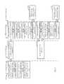
- FIG. 3is a flowchart illustrating dynamic advertisement routing according to an example of the present disclosure.
- the example method 300is described with reference to the flowchart illustrated in FIG. 3 , it will be appreciated that many other methods of performing the acts associated with the method 300 may be used. For example, the order of some of the blocks may be changed, certain blocks may be combined with other blocks, and some of the blocks described are optional.
- the method 300may be performed by processing logic that may comprise hardware (circuitry, dedicated logic, etc.), software, or a combination of both. In an example, the method is performed by a load balancer service 140 in conjunction with routing service 141 and latency service 142 .
- a plurality of internet protocol addressesis stored in a routing pool, including first, second, and third internet protocol addresses respectively associated with first, second, and third target nodes of a plurality of target nodes (block 310 ).
- discovery service 241may store, in routing pool 155 , IP addresses 170 , 172 , and 174 which are respectively associated with NICs 250 , 252 , and 255 A. IP addresses 170 , 172 , and 174 may thereby be respectively associated with nodes 210 , 211 , and 212 .
- discovery service 241may be configured to repeatedly send requests to a single domain name (e.g., a domain name of advertiser 220 ) and each of nodes 210 , 211 , and 212 may host a shared common application (e.g., ad services 230 , 232 , and 235 ). In a further example, discovery service 241 may later be randomly connected to a fourth IP address from sending requests to the domain name of advertiser 220 , and add IP address 176 associated with NIC 255 B to routing pool 155 . In the example, discovery service 241 may be unable to distinguish that NIC 255 B and IP address 176 belong to a second NIC on node 212 rather than another stand alone node.
- a single domain namee.g., a domain name of advertiser 220
- each of nodes 210 , 211 , and 212may host a shared common application (e.g., ad services 230 , 232 , and 235 ).
- implementation of the routing pool 155circumvents queries to DNS for requests with actual payloads by allowing for direct connections to target IP addresses (e.g., IP addresses 170 , 172 , 174 , and 176 ).
- target IP addressese.g., IP addresses 170 , 172 , 174 , and 176 .
- a ping with DNS to a closely situated servermay take 15 ms-40 ms, while a direct ping to the IP address of the same server may take 1 ms-10 ms.
- Each of the plurality of internet protocol addresses in the routing poolis pinged, including at least the first, second, and third internet protocol addresses, through each of a first load balancer network interface and a second load balancer network interface (block 315 ).
- routing service 141may ping IP addresses 170 , 172 , and 174 through both of the virtual network interfaces 187 A-B.
- routing service 141may determine that a connection to IP address 170 is faster through virtual network interface 187 A than through virtual network interface 187 B.
- a preferencemay be selected for virtual network interface 187 B to connect to IP address 172
- virtual network interface 187 Amay be selected to connect to IP address 174 .
- At least one of a first network route to the first target node, a second network route to the second target node, and a third network route to the third target nodeis updated based on a first plurality of ping responses (block 320 ).
- routing service 141may receive ping responses from each of IP addresses 170 , 172 , and 174 through each of virtual network interfaces 187 A-B.
- routing service 141may record the preferred virtual network interface (e.g., 187 A or 187 B) for connecting to each IP address (e.g., IP addresses 170 , 172 , and 174 ) in routing pool 155 to a routing table 270 as a network route (e.g., network routes 260 , 262 , and 264 ).
- routing service 141may also directly update latency cache 150 with ping latencies from the dynamic network route discovery process.
- a first communication sessionis established with the first target node through the first network route, a second communication session with the second target node through the second network route, and a third communication session with the third target node through the third network route (block 325 ).
- routing service 141may establish a communication session with each target IP address (e.g., IP addresses 170 , 172 , and 174 ) through each load balancer network interface (e.g., virtual network interfaces 187 A-B) prior to pinging the IP addresses 170 , 172 , and 174 .
- these communication sessionsmay be kept open to speed up sending requests through the network routes underlying the communication sessions.
- the latency service 142may establish communication sessions after preferred routes have already been selected and stored in routing table 270 .
- communication sessionsmay be established when the load balancer transmits the first request with an actual payload to the target IP address.
- the communication sessionmay be kept open after a response to the request to the target IP address is received by the load balancer.
- the first communication sessionis established through network route 260 via virtual network interface 187 A
- the second communication sessionis established through network route 262 via virtual network interface 187 A
- the third communication sessionis established through network route 264 via virtual network interface 187 B.
- the first communication sessionis established between a port on VM 116 and another port on target node 210 .
- the respective portsmay be associated respectively with an IP address of virtual network interface 187 A and IP address 170 of NIC 250 .
- the first, second, and the third internet protocol addressesare pinged (block 330 ).
- the latency service 142pings each of the target IP addresses (e.g., IP addresses 170 , 172 , and 174 ) in routing pool 155 .
- latency service 142pings the target IP addresses through a default network route (e.g., network routes 260 , 262 , and 264 ) associated with the respective target IP address and/or target node.
- a latency of each target IP addressis computed based on a ping response from each IP address.
- First, second, and third latencies in a latency cacheare updated based on a second plurality of ping responses (block 335 ).
- latency service 142may record a respective calculated latency (e.g., latencies 160 , 162 , and 164 ) in latency cache 150 for each target IP address (e.g., IP addresses 170 , 172 , and 174 ) pinged.
- target IP addresse.g., IP addresses 170 , 172 , and 174
- latency service 142may further categorize each target IP address (e.g., IP addresses 170 , 172 , and 174 ) with a performance characteristic based on a respective latency (e.g., latencies 160 , 162 , and 164 ).
- node 210may be classified as high performance based on latency 160
- node 211may be classified as medium performance based on latency 162
- node 212may be classified as low performance based on latency 164 .
- latency service 142 's ping to target IP address 174may time out, and target IP address 174 may be classified as non-operational.
- load balancer 140may not send requests with actual payload data to target IP addresses classified as non-operational.
- a timeout value that latency service 142 waits for a response to a pingmay be configurable.
- routing service 141may set network route 266 between virtual network interface 187 B and NIC 255 B as the default network route for IP address 176 .
- latency service 142may then ping IP address 176 and record a latency 166 associated with IP address 176 in latency cache 150 .
- a first request directed to the plurality of target nodesis received (block 340 ).
- load balancer 140may receive a request from a publisher of content (e.g., a news website) for bids for an available ad slot (e.g., a banner ad on the front page).
- load balancer 140may be configured to forward the request to advertiser 220 to solicit a bid for the ad slot.
- the first requestis determined to be sent to the first target node based on the latency cache (block 345 ).
- latency 164may have breached a time out threshold thereby removing IP address 174 and node 212 from contention for receiving the request.
- load balancer 140may employ any form of random or pseudo random selection process to decide between forwarding the request to node 210 vs. node 211 .
- node 210is selected based on a random distribution.
- the load balancer 140may assess the request to classify the request with a priority.
- the requestmay include a priority value and/or a timeout value, and the load balancer 140 may assign a priority classification to the request based on the priority value and/or the timeout value.
- a priority valuemay be based on an expected response deadline for loading an ad for the ad slot.
- a priority valuemay also be based on historical data relating to effectiveness of ad placements with a particular publisher (e.g., a publisher whose ad slot generates more click-throughs and/or purchases may be in higher demand and therefore receive priority over a less effective publisher's ad slot).
- a timeout valuemay be communicated by a publisher as an effective “last call” for bids, after which bids will be ignored.
- a timeout valuemay be calculated based on historical bid success data for a particular publisher.
- a publishermay implement dynamic advertisement routing to enhance the response time of bid requests to ad agencies and/or directly to advertisers.
- the first requestis forwarded to the first target node via the first network route (block 350 ).
- load balancer 140may forward the first request to node 210 via network route 260 .
- a communication session on network route 260may be established and maintained in an open state to avoid the first request from having to engage in a handshake process with target node 210 .
- a second request classified as high priority, a third request classified as medium priority, and a fourth request classified as low prioritymay subsequently be received by load balancer 140 .
- target node 210may be high performance
- target node 211may be medium performance
- target node 212may be low performance based respectively on latencies 160 , 162 , and 164 .
- the second requestmay be sent to target node 210 via network route 260 , the second request to target node 211 via network route 262 , and the third request to target node 212 via network route 264 .
- the third requestmay be sent to target node 211 instead.
- latency service 142may again ping IP address 174 associated with node 212 , and this time, a new latency calculated from the ping response to the new ping may fall under the latency threshold.
- the latency servicemay then update latency cache 150 indicating that IP address 174 and therefore node 212 has been elevated to low performance status.
- another request classified as low priority received by load balancer 140may then be sent to node 212 via network route 264 .
- routing pool 155stores a current list of all known IP addresses of a target ad server farm (e.g., advertiser 220 ) (block 410 ).
- a routing service 141may ping each IP address in the routing pool 155 (e.g., IP addresses 170 , 172 , 174 , and 176 ) with each load balancer network interface in system 400 (e.g., virtual network interfaces 187 A-B) (block 412 ).
- routing service 141may determine which network interface (e.g., virtual network interfaces 187 A or 187 B) has the lowest ping response time for each of IP addresses 170 , 172 , 174 , and 176 (block 414 ).
- routing service 141may then save the route from the fastest network interface (e.g., virtual network interfaces 187 A or 187 B) to each of IP addresses 170 , 172 , 174 , and 176 to routing table 270 (block 416 ).
- routing table 270may be updated with the network interface (e.g., virtual network interfaces 187 A or 187 B) to use to connect to each of IP addresses 170 , 172 , 174 , and 176 in routing pool 155 (block 418 ).
- each separate instance of a load balancer servicee.g., load balancer services 140 and 145
- routing service 141 and routing service 146may be components of a singular routing service that can access each virtual network interface (e.g., virtual network interfaces 187 A-D) on each VM (e.g., VMs 116 and 118 ) in system 100 .
- routing pool 155may be shared between load balancer service instances 140 and 145 and/or stored as separate copies accessed by each load balancer service 140 and 145 separately.
- discovery service 241accesses a target ad server farm (e.g., advertiser 220 ), through a DNS address (e.g., a hostname URL) (block 420 ).
- discovery service 241may perform such access with actual payload data for an ad request, or without payload data (e.g., through pinging the hostname URL).
- DNSresolves the hostname URL and allows discovery service 241 to connect to the target node
- discovery service 241may retrieve the IP address of the currently connected target node (block 422 ). In the example, discovery service 241 may then determine whether the retrieved IP address is present in routing pool 155 (block 424 ).
- discovery service 241may add the new IP address to the routing pool 155 (block 426 ). In the example, the new IP address is added to routing pool 155 (block 430 ). When queried, routing pool 155 then provides an updated list of IP addresses including the new IP address (block 432 ). In an example, discovery service 241 may update routing pool 155 in real time and any additional IP addresses may be pinged by routing service 141 the next time routing service 141 executes. If the IP address is present in the routing pool 155 , discovery service 241 may loop back and repeat the access of the target ad server farm (e.g., advertiser 220 ) through the DNS address (block 428 ).
- target ad server farme.g., advertiser 220
- discovery service 241may continually execute the discovery process periodically (block 450 ).
- discovery service 241may be configured to execute more or less frequently based on a frequency of newly discovered IP addresses. For example, discovery service 241 may be configured to execute once a minute, but when no new IP address has been discovered in thirty attempts, discovery service 241 may be dialed back to execute once every 5 minutes. In the example, if two discoveries are then made within ten attempts, discovery service 241 may be reconfigured to execute every five seconds since the two discoveries may be indicative of new servers being brought online by advertiser 220 with a new range of IP addresses.
- routing service 141may again ping each IP address in the routing pool 155 (e.g., IP addresses 170 , 172 , 174 , and 176 ) with each load balancer network interface in system 400 (e.g., virtual network interfaces 187 A-B) including pinging the new IP address discovered by discovery service 241 (block 434 ).
- routing service 141may determine which network interface (e.g., virtual network interfaces 187 A or 187 B) has the lowest ping response time for each of IP addresses 170 , 172 , 174 , 176 , and the new IP address (block 414 ).
- routing service 141may then save the route from the fastest network interface (e.g., virtual network interfaces 187 A or 187 B) to each of IP addresses 170 , 172 , 174 , 176 , and the new IP address to routing table 270 (block 438 ).
- routing table 270may be updated with the network interface (e.g., virtual network interfaces 187 A or 187 B) to use to connect to each of IP addresses 170 , 172 , 174 , 176 , and the new IP address in routing pool 155 (block 440 ).
- routing service 141may continually execute to validate the current fastest network route to each target IP address.
- a routing servicewould continually rotate through each load balancer network interface and target IP address combination to keep preferred routes up to date in the routing table.
- a routing servicemay skip the remaining load balancer network interfaces for that target IP address until a later rotation as the server for the target IP address is likely offline.
- FIG. 5is a flow diagram illustrating target prioritization through latency detection in a dynamic advertisement routing system according to an example of the present disclosure.
- FIG. 5is a flow diagram illustrating target prioritization through latency detection in a dynamic advertisement routing system according to an example of the present disclosure.
- routing pool 155stores a current list of all known IP addresses of a target ad server farm (e.g., advertiser 220 ) (block 510 ).
- a latency service 142may ping each IP address in the routing pool 155 (e.g., IP addresses 170 , 172 , 174 , and 176 ) via a default network route stored in routing table 270 (block 512 ).
- latency service 142may ping the target IP addresses 170 , 172 , 174 , and 176 much more frequently than routing service 141 , since latency service 142 only pings once per target address per cycle vs. once for each load balancer network interface in the case of routing service 141 .
- latency service 142determines a latency (e.g., latency 160 , 162 , 164 , and 166 ) for each IP address in routing pool 155 (e.g., IP addresses 170 , 172 , 174 , and 176 ) (block 514 ).
- latency 160may be calculated based on a ping response time to IP address 170 .
- latency service 142may discard the latency result for the first IP address 170 due to the ping to IP address 170 timing out (block 516 ). In an example, discarding a latency result may keep any actual ad requests from being sent to IP address 170 since no entry would be made for IP address 170 in latency cache 150 .
- the remaining IP addressesmay be sorted into high, medium, and low performance bands based on latency cut offs (block 518 ). For example, responses taking over 10 ms may be discarded as time outs, responses over 7 ms may be classified as low performance, responses over 5 ms may be classified as medium performance, and responses faster than 5 ms may be classified as high performance.
- IP address 172may be high performance
- IP address 174may be medium performance
- IP address 176may be low performance.
- the sorted IP addresses 172 , 174 , and 176may be saved in latency cache 150 (block 520 ).
- Latency cache 150may then be updated with a list of targets for high, medium, and low performance (block 522 ).
- IP addressese.g., IP addresses 172 , 174 , and 176
- IP addresses 172 , 174 , and 176may be stored in entries in latency cache 150 along with numerical latency values.
- latency cache 150may store IP addresses (e.g., IP addresses 172 , 174 , and 176 ) in performance bands without numerical latency values.
- routing service 141again pings each IP addresses (e.g., IP addresses 170 , 172 , 174 , and 176 ) in routing pool 155 with each load balancer network interface (e.g., virtual network interfaces 187 A-D) (block 530 ).
- routing service 141may determine that virtual network interface 187 B now has lower latency to IP address 170 than virtual network interface 187 A (block 532 ).
- Routing service 141may then update routing table 270 to send messages to IP address 170 through virtual network interface 187 B instead of virtual network interface 187 A (block 534 ).
- latency service 142may again retrieve a current list of IP addresses (e.g., IP addresses 170 , 172 , 174 , and 176 ) from routing pool 155 (block 540 ).
- routing pool 155may send the current list of IP addresses (e.g., IP addresses 172 , 174 , and 176 ) (block 542 ).
- IP address 170is included in the list from routing pool 155 even though latency service 142 's previous ping to IP address 170 timed out.
- latency service 142pings each IP addresses (e.g., IP addresses 172 , 174 , and 176 ) in routing pool 155 , including pinging IP address 170 through virtual network interface 187 B instead of virtual network interface 187 A (block 544 ).
- routing service 141may have updated the network route in routing table 270 for IP address 170 prior to latency service 142 pinging IP address 170 again.
- latency service 142may determine that IP address 170 now sorts into the medium performance band (block 546 ).
- latency service 142saves IP address 170 to latency cache 150 (block 142 ).
- IP address 170is added to the list of medium performance targets in latency cache 150 (block 550 ).
- no other changesmay have occurred for the performance banding of IP addresses 172 , 174 , and 176 .
- the performance banding of IP addresses 172 , 174 , and 176may also be readjusted based on the latest pinging by latency service 142 , and may be updated in latency cache 150 .
- blocks 512 - 522may be performed independently of blocks 530 - 540 , with the latency service 142 executing multiple times to test the current performance of the IP addresses 170 , 172 , 174 , and 176 for each time the routing service 141 tests for preferable network routes.
- a system hosting a load balancer service along with a routing service and a latency servicemay have eight, sixteen, or even one hundred or more network interfaces whether physical or virtualized.
- the routing servicemay require significantly longer to ping each IP address in a routing pool than the latency service, because of the multiplicative effect on the number of pings that are required to work through the list of IP addresses caused by the addition of more network interfaces.
- the latency servicemay be configured with a more aggressive time out than the routing service where the routing service may be confirming whether a target node is active, while the latency service is prioritizing whether the given target node is performing well enough to be used for a request with an active payload.
- the routing servicemay trigger significantly more timeouts (e.g., where multiple routes to the same struggling or inoperative target node are tested).
- the latency servicemay be configured to time out after 20 ms, while the routing service may be configured to time out after 200 ms.
- the latency servicewould take, as a rough upper bound, at most 2,000 ms to execute, (e.g., 20 ms to time out and one hundred target IP addresses to try).
- 20 msmay be configured as a lower bound for “low performance” connections.
- the routing servicemay take up to 200,000 ms to execute if every possible combination timed out. In a typical system with ten network interfaces, the routing service may typically take fifteen to twenty times as long to execute as the latency service. Therefore, the separation of the polling of the latency service and the routing service allows prioritization and performance data in the latency cache to be significantly more up to date. In an example, the latency service may also consider a wider range of data than the latest ping result in determining a performance band for a given target node. For example, a rolling and/or weighted average ping response time over a given time period (e.g., five minutes) may be used.
- ping response timemay be combined with other factors, such as a quantity of outstanding requests, to determine the performance band for a given target node. For example, a target node that has not responded yet to two or more previous requests may be dropped by a performance band (e.g., high to medium or medium to low).
- FIG. 6is a flow diagram illustrating dynamic request handling in a dynamic advertisement routing system according to an example of the present disclosure.
- FIG. 6is a flow diagram illustrating dynamic request handling in a dynamic advertisement routing system according to an example of the present disclosure.
- FIG. 6it will be appreciated that many other methods of performing the acts associated with FIG. 6 may be used.
- the order of some of the blocksmay be changed, certain blocks may be combined with other blocks, and some of the blocks described are optional.
- the methodsmay be performed by processing logic that may comprise hardware (circuitry, dedicated logic, etc.), software, or a combination of both.
- a load balancer service 140 and a latency service 142interface with a latency cache 150 to send requests to selected target IP addresses.
- load balancer service 140receives a first request directed at a target ad server farm (e.g., advertiser 220 ) (block 610 ).
- load balancer service 140determines that the request is a high priority request (block 612 ).
- the requestmay be flagged with a time stamp indicating a short window for responding with an ad bid for an ad slot.
- the source of the requeste.g., a publisher
- load balancer service 140requests a high performance target from latency cache 150 (block 614 ).
- latency cache 150may respond by sending load balancer service 140 the current list of high performance IP addresses (block 616 ).
- load balancer service 140forwards the first request to target node 210 included in the list of high performance IP addresses (e.g., IP address 170 ) (block 618 ).
- IP address 170may be selected from the list of high performance IP addresses randomly by load balancer service 140 .
- latency cache 150may send only one random IP address that is flagged as high performance rather than the whole list of high performance IP addresses.
- load balancer service 140tracks which target IP addresses have recently received requests. For example, load balancer service 140 may ensure that no single target IP address is flooded with requests.
- the target node associated with the target IP addressmay be unable to respond to the requests quickly enough to respond in real-time, resulting in the queueing of requests and sub-optimal response times.
- an alternative sorting methodmay be used (e.g., sorting by ping response times directly).
- a requestmay be sent to any target IP address whose calculated response time may meet a critical timeout value for responding to the request.
- Latency service 142may execute concurrently with the processing of the first request by load balancer service 140 .
- latency service 142may ping each IP address (e.g., IP addresses 170 , 172 , 174 , and 176 ) in routing pool 155 via a network route (e.g., network routes 260 , 262 , 264 , and 266 ) stored in routing table 270 (block 620 ).
- network routee.g., network routes 260 , 262 , 264 , and 266
- latency service 142may determine a latency (e.g., latencies 160 , 162 , 164 , and 166 ) for each IP address 170 , 172 , 174 , and 176 in routing pool 155 (block 622 ).
- the latency result 160 of IP address 170may be downgraded to low performance due to the response time of the latest ping from latency service 142 (block 624 ).
- traffic to IP address 170may have become congested due to its previous low latency and high performance.
- a switch in the route to IP address 170may be restarting for maintenance.
- latency service 142updates latency cache 150 indicating that IP address 170 is now low performance (block 626 ).
- Latency cache 150may save the updated performance bands for the various IP addresses 170 , 172 , 174 and 176 , including saving IP address 170 as low performance (block 628 ).
- load balancer service 140may receive a second request directed at the target ad server farm (e.g., advertiser 220 ) (block 630 ).
- load balancer service 140determines that the second request is low priority (block 632 ).
- the second requestmay have a response time deadline that should be met even by a low performance target node (e.g., the updated node 210 ).
- historical datamay show that bids to the publisher for the second request rarely win an ad slot and/or generate low returns even when bids are won.
- load balancer service 140requests a low performance target from latency cache 150 (block 634 ).
- latency cache 150responds by sending a current list of low performance IP addresses, including IP address 170 (block 636 ).
- Load balancer service 140then forwards the second request to node 210 (e.g., IP address 170 ) selected at random from the list of low performance IP addresses (block 638 ).
- load balancer service 140keeps track of where requests have been sent.
- load balancer service 140receives a third request directed at the target ad server farm (e.g., advertiser 220 ) (block 640 ).
- load balancer service 140may receive the third request prior to receiving responses to the first two requests from IP address 170 .
- the third requestmay be determined to be low priority (block 642 ).
- load balancer service 140may again request an updated list of low performance IP addresses from latency cache 150 , and may receive an updated list of low performance IP addresses. In another example, load balancer service 140 may re-use the previous list of low performance IP addresses due to the temporal proximity between receiving the second and third requests. In an example, load balancer service 140 sends the third request to target node 211 to avoid flooding target node 210 with requests (block 644 ). In the example, both IP address 170 and IP address 172 may be on the list of low performance IP addresses, but IP address 170 may be removed from contention for receiving the third request due to the first two outstanding requests being processed by target node 210 .
- a connectionis constantly maintained between a network interface (e.g., virtual network interfaces 187 A-D) of system 100 , and each target IP address (e.g., IP addresses 170 , 172 , 174 , and 176 ) of advertiser 220 to allow a request to be sent to a selected IP address (e.g., IP addresses 170 , 172 , 174 , or 176 ) without requiring a new handshake to establish a connection.
- a network interfacee.g., virtual network interfaces 187 A-D
- each target IP addresse.g., IP addresses 170 , 172 , 174 , and 176
- a selected IP addresse.g., IP addresses 170 , 172 , 174 , or 176
- connecting directly to a target IP address bypassing DNSmay decrease latency by up to 20 ms. In an example, by eliminating sending requests to target nodes temporarily experiencing networking or other difficulties, failures and other outliers may be greatly
- employing dynamic advertisement routingmay reduce average response times for ad bid requests from 500 ms-1,000 ms down to 200 ms or less while eliminating the majority of bids lost to timeout.
- the larger the system growse.g., with more network interfaces and more connections
- the better the performance of the selected top performing network routemay be. For example, if one hundred network interfaces are tested for connecting to a target IP address, the top performer of the one hundred connections would be likely be at least in the top ten percent of possible routing performances.
- the more target nodesare available, the more high performing load balancer network interface and target node combinations may be found. As such, the larger the system, the stronger the performance of a system executing dynamic advertisement routing.
Landscapes
- Engineering & Computer Science (AREA)
- Computer Networks & Wireless Communication (AREA)
- Signal Processing (AREA)
- Software Systems (AREA)
- Theoretical Computer Science (AREA)
- General Physics & Mathematics (AREA)
- Physics & Mathematics (AREA)
- General Engineering & Computer Science (AREA)
- Environmental & Geological Engineering (AREA)
- General Health & Medical Sciences (AREA)
- Cardiology (AREA)
- Health & Medical Sciences (AREA)
- Data Exchanges In Wide-Area Networks (AREA)
Abstract
Description
Claims (35)
Priority Applications (4)
| Application Number | Priority Date | Filing Date | Title |
|---|---|---|---|
| US15/463,820US9832128B1 (en) | 2017-03-20 | 2017-03-20 | Dynamic advertisement routing |
| US15/815,063US9992121B1 (en) | 2017-03-20 | 2017-11-16 | Dynamic advertisement routing |
| PCT/US2017/063296WO2018174965A1 (en) | 2017-03-20 | 2017-11-27 | Dynamic advertisement routing |
| US15/996,112US10999201B2 (en) | 2017-03-20 | 2018-06-01 | Dynamic advertisement routing |
Applications Claiming Priority (1)
| Application Number | Priority Date | Filing Date | Title |
|---|---|---|---|
| US15/463,820US9832128B1 (en) | 2017-03-20 | 2017-03-20 | Dynamic advertisement routing |
Related Child Applications (1)
| Application Number | Title | Priority Date | Filing Date |
|---|---|---|---|
| US15/815,063ContinuationUS9992121B1 (en) | 2017-03-20 | 2017-11-16 | Dynamic advertisement routing |
Publications (1)
| Publication Number | Publication Date |
|---|---|
| US9832128B1true US9832128B1 (en) | 2017-11-28 |
Family
ID=60407803
Family Applications (3)
| Application Number | Title | Priority Date | Filing Date |
|---|---|---|---|
| US15/463,820ActiveUS9832128B1 (en) | 2017-03-20 | 2017-03-20 | Dynamic advertisement routing |
| US15/815,063ActiveUS9992121B1 (en) | 2017-03-20 | 2017-11-16 | Dynamic advertisement routing |
| US15/996,112ActiveUS10999201B2 (en) | 2017-03-20 | 2018-06-01 | Dynamic advertisement routing |
Family Applications After (2)
| Application Number | Title | Priority Date | Filing Date |
|---|---|---|---|
| US15/815,063ActiveUS9992121B1 (en) | 2017-03-20 | 2017-11-16 | Dynamic advertisement routing |
| US15/996,112ActiveUS10999201B2 (en) | 2017-03-20 | 2018-06-01 | Dynamic advertisement routing |
Country Status (2)
| Country | Link |
|---|---|
| US (3) | US9832128B1 (en) |
| WO (1) | WO2018174965A1 (en) |
Cited By (62)
| Publication number | Priority date | Publication date | Assignee | Title |
|---|---|---|---|---|
| US10063632B1 (en)* | 2017-12-22 | 2018-08-28 | Engine Media, Llc | Low-latency high-throughput scalable data caching |
| US10432737B2 (en) | 2017-10-12 | 2019-10-01 | Engine Media, Llc | Geopartitioned data caching |
| US10938693B2 (en) | 2017-06-22 | 2021-03-02 | Nicira, Inc. | Method and system of resiliency in cloud-delivered SD-WAN |
| US10959098B2 (en) | 2017-10-02 | 2021-03-23 | Vmware, Inc. | Dynamically specifying multiple public cloud edge nodes to connect to an external multi-computer node |
| US10958479B2 (en) | 2017-10-02 | 2021-03-23 | Vmware, Inc. | Selecting one node from several candidate nodes in several public clouds to establish a virtual network that spans the public clouds |
| US10992558B1 (en) | 2017-11-06 | 2021-04-27 | Vmware, Inc. | Method and apparatus for distributed data network traffic optimization |
| US10992568B2 (en) | 2017-01-31 | 2021-04-27 | Vmware, Inc. | High performance software-defined core network |
| US10999165B2 (en) | 2017-10-02 | 2021-05-04 | Vmware, Inc. | Three tiers of SaaS providers for deploying compute and network infrastructure in the public cloud |
| US10999137B2 (en) | 2019-08-27 | 2021-05-04 | Vmware, Inc. | Providing recommendations for implementing virtual networks |
| US10999100B2 (en) | 2017-10-02 | 2021-05-04 | Vmware, Inc. | Identifying multiple nodes in a virtual network defined over a set of public clouds to connect to an external SAAS provider |
| US11044190B2 (en) | 2019-10-28 | 2021-06-22 | Vmware, Inc. | Managing forwarding elements at edge nodes connected to a virtual network |
| US11050588B2 (en) | 2013-07-10 | 2021-06-29 | Nicira, Inc. | Method and system of overlay flow control |
| US11089111B2 (en)* | 2017-10-02 | 2021-08-10 | Vmware, Inc. | Layer four optimization for a virtual network defined over public cloud |
| US11115480B2 (en) | 2017-10-02 | 2021-09-07 | Vmware, Inc. | Layer four optimization for a virtual network defined over public cloud |
| US11121962B2 (en) | 2017-01-31 | 2021-09-14 | Vmware, Inc. | High performance software-defined core network |
| US11212140B2 (en) | 2013-07-10 | 2021-12-28 | Nicira, Inc. | Network-link method useful for a last-mile connectivity in an edge-gateway multipath system |
| US11223514B2 (en) | 2017-11-09 | 2022-01-11 | Nicira, Inc. | Method and system of a dynamic high-availability mode based on current wide area network connectivity |
| US11245641B2 (en) | 2020-07-02 | 2022-02-08 | Vmware, Inc. | Methods and apparatus for application aware hub clustering techniques for a hyper scale SD-WAN |
| US11252079B2 (en) | 2017-01-31 | 2022-02-15 | Vmware, Inc. | High performance software-defined core network |
| US11288699B2 (en) | 2018-07-13 | 2022-03-29 | Pubwise, LLLP | Digital advertising platform with demand path optimization |
| US11349722B2 (en) | 2017-02-11 | 2022-05-31 | Nicira, Inc. | Method and system of connecting to a multipath hub in a cluster |
| US11363124B2 (en) | 2020-07-30 | 2022-06-14 | Vmware, Inc. | Zero copy socket splicing |
| US11374904B2 (en) | 2015-04-13 | 2022-06-28 | Nicira, Inc. | Method and system of a cloud-based multipath routing protocol |
| US11375005B1 (en) | 2021-07-24 | 2022-06-28 | Vmware, Inc. | High availability solutions for a secure access service edge application |
| US11381499B1 (en) | 2021-05-03 | 2022-07-05 | Vmware, Inc. | Routing meshes for facilitating routing through an SD-WAN |
| US11394640B2 (en) | 2019-12-12 | 2022-07-19 | Vmware, Inc. | Collecting and analyzing data regarding flows associated with DPI parameters |
| US11418997B2 (en) | 2020-01-24 | 2022-08-16 | Vmware, Inc. | Using heart beats to monitor operational state of service classes of a QoS aware network link |
| US20220263756A1 (en)* | 2020-01-13 | 2022-08-18 | Tencent Technology (Shenzhen) Company Limited | Routing control method and apparatus, electronic device, and storage medium |
| US11444865B2 (en) | 2020-11-17 | 2022-09-13 | Vmware, Inc. | Autonomous distributed forwarding plane traceability based anomaly detection in application traffic for hyper-scale SD-WAN |
| US11444872B2 (en) | 2015-04-13 | 2022-09-13 | Nicira, Inc. | Method and system of application-aware routing with crowdsourcing |
| CN115065699A (en)* | 2022-06-08 | 2022-09-16 | 深圳市元征科技股份有限公司 | Route activation method, device, equipment and medium based on remote diagnosis |
| US11489783B2 (en) | 2019-12-12 | 2022-11-01 | Vmware, Inc. | Performing deep packet inspection in a software defined wide area network |
| US11489720B1 (en) | 2021-06-18 | 2022-11-01 | Vmware, Inc. | Method and apparatus to evaluate resource elements and public clouds for deploying tenant deployable elements based on harvested performance metrics |
| US11575600B2 (en) | 2020-11-24 | 2023-02-07 | Vmware, Inc. | Tunnel-less SD-WAN |
| US11601356B2 (en) | 2020-12-29 | 2023-03-07 | Vmware, Inc. | Emulating packet flows to assess network links for SD-WAN |
| US11606286B2 (en) | 2017-01-31 | 2023-03-14 | Vmware, Inc. | High performance software-defined core network |
| US11677720B2 (en) | 2015-04-13 | 2023-06-13 | Nicira, Inc. | Method and system of establishing a virtual private network in a cloud service for branch networking |
| US11706127B2 (en) | 2017-01-31 | 2023-07-18 | Vmware, Inc. | High performance software-defined core network |
| US11706126B2 (en) | 2017-01-31 | 2023-07-18 | Vmware, Inc. | Method and apparatus for distributed data network traffic optimization |
| US11729065B2 (en) | 2021-05-06 | 2023-08-15 | Vmware, Inc. | Methods for application defined virtual network service among multiple transport in SD-WAN |
| US11792127B2 (en) | 2021-01-18 | 2023-10-17 | Vmware, Inc. | Network-aware load balancing |
| US11909815B2 (en) | 2022-06-06 | 2024-02-20 | VMware LLC | Routing based on geolocation costs |
| US11943146B2 (en) | 2021-10-01 | 2024-03-26 | VMware LLC | Traffic prioritization in SD-WAN |
| US11979325B2 (en) | 2021-01-28 | 2024-05-07 | VMware LLC | Dynamic SD-WAN hub cluster scaling with machine learning |
| US12009987B2 (en) | 2021-05-03 | 2024-06-11 | VMware LLC | Methods to support dynamic transit paths through hub clustering across branches in SD-WAN |
| US12015536B2 (en) | 2021-06-18 | 2024-06-18 | VMware LLC | Method and apparatus for deploying tenant deployable elements across public clouds based on harvested performance metrics of types of resource elements in the public clouds |
| US12034570B2 (en) | 2022-03-14 | 2024-07-09 | T-Mobile Usa, Inc. | Multi-element routing system for mobile communications |
| US12034587B1 (en) | 2023-03-27 | 2024-07-09 | VMware LLC | Identifying and remediating anomalies in a self-healing network |
| US12047282B2 (en) | 2021-07-22 | 2024-07-23 | VMware LLC | Methods for smart bandwidth aggregation based dynamic overlay selection among preferred exits in SD-WAN |
| US12057993B1 (en) | 2023-03-27 | 2024-08-06 | VMware LLC | Identifying and remediating anomalies in a self-healing network |
| US12166661B2 (en) | 2022-07-18 | 2024-12-10 | VMware LLC | DNS-based GSLB-aware SD-WAN for low latency SaaS applications |
| US12184557B2 (en) | 2022-01-04 | 2024-12-31 | VMware LLC | Explicit congestion notification in a virtual environment |
| US12218845B2 (en) | 2021-01-18 | 2025-02-04 | VMware LLC | Network-aware load balancing |
| US12237990B2 (en) | 2022-07-20 | 2025-02-25 | VMware LLC | Method for modifying an SD-WAN using metric-based heat maps |
| US12250114B2 (en) | 2021-06-18 | 2025-03-11 | VMware LLC | Method and apparatus for deploying tenant deployable elements across public clouds based on harvested performance metrics of sub-types of resource elements in the public clouds |
| CN119603143A (en)* | 2024-11-27 | 2025-03-11 | 天翼云科技有限公司 | Service timeliness optimization method, device, computer equipment, readable storage medium and program product |
| US12261777B2 (en) | 2023-08-16 | 2025-03-25 | VMware LLC | Forwarding packets in multi-regional large scale deployments with distributed gateways |
| US12267364B2 (en) | 2021-07-24 | 2025-04-01 | VMware LLC | Network management services in a virtual network |
| US12355655B2 (en) | 2023-08-16 | 2025-07-08 | VMware LLC | Forwarding packets in multi-regional large scale deployments with distributed gateways |
| US12368676B2 (en) | 2021-04-29 | 2025-07-22 | VMware LLC | Methods for micro-segmentation in SD-WAN for virtual networks |
| US12425332B2 (en) | 2023-03-27 | 2025-09-23 | VMware LLC | Remediating anomalies in a self-healing network |
| US12425395B2 (en) | 2022-01-15 | 2025-09-23 | VMware LLC | Method and system of securely adding an edge device operating in a public network to an SD-WAN |
Families Citing this family (4)
| Publication number | Priority date | Publication date | Assignee | Title |
|---|---|---|---|---|
| US11016793B2 (en)* | 2018-11-26 | 2021-05-25 | Red Hat, Inc. | Filtering based containerized virtual machine networking |
| CN109981377B (en)* | 2019-04-10 | 2022-03-01 | 北京搜狐新媒体信息技术有限公司 | Distributed data center link monitoring method and system |
| US12309067B2 (en) | 2019-09-11 | 2025-05-20 | Intel Corporation | Hardware queue scheduling for multi-core computing environments |
| CN112134751B (en)* | 2020-09-08 | 2021-06-22 | 广东云下汇金科技有限公司 | Method and system for monitoring network quality of overseas ISPs |
Citations (18)
| Publication number | Priority date | Publication date | Assignee | Title |
|---|---|---|---|---|
| US20030065763A1 (en)* | 1999-11-22 | 2003-04-03 | Swildens Eric Sven-Johan | Method for determining metrics of a content delivery and global traffic management network |
| US20080065479A1 (en) | 2006-09-12 | 2008-03-13 | Yahoo! Inc. | System and method for optimizing online advertisement auctions by applying linear programming using special ordered sets |
| US20080228564A1 (en) | 2007-03-12 | 2008-09-18 | Microsoft Corporation | Weighted-Parameter Auction |
| US20090190482A1 (en)* | 2008-01-30 | 2009-07-30 | Cisco Technology, Inc., A Corporation Of California | Relative One-Way Delay Measurements Over Multiple Paths Between Devices |
| US20100145809A1 (en) | 2006-12-19 | 2010-06-10 | Fox Audience Network, Inc. | Applications for auction for each individual ad impression |
| US20110040635A1 (en) | 2009-08-14 | 2011-02-17 | Willard Simmons | Dynamic targeting algorithms for real-time valuation of advertising placements |
| US20110075582A1 (en)* | 2009-09-25 | 2011-03-31 | Fujitsu Limited | Delay time measurement apparatus, storage medium storing delay time measurement program and network system |
| US20120144023A1 (en)* | 2010-12-03 | 2012-06-07 | Salesforce.Com, Inc. | Method and system for validating configuration data in a multi-tenant environment |
| US20130066705A1 (en) | 2011-09-09 | 2013-03-14 | Dennoo Inc. | Methods and systems for processing and displaying advertisements of variable lengths |
| US20130117427A1 (en)* | 2011-11-08 | 2013-05-09 | Hitachi, Ltd. | Computer system, and method for managing resource pool information |
| US20140058849A1 (en) | 2012-08-20 | 2014-02-27 | OpenX Technologies, Inc. | System and Methods for Generating Dynamic Market Pricing for Use in Real-Time Auctions |
| US20140105024A1 (en)* | 2009-11-13 | 2014-04-17 | Exalt Communications Incorporated | Apparatus for ethernet traffic aggregation of radio links |
| US8831987B2 (en) | 2006-12-19 | 2014-09-09 | The Rubicon Project | Managing bids in a real-time auction for advertisements |
| US20150051986A1 (en) | 2013-08-16 | 2015-02-19 | OpenX Technologies, Inc. | System Architecture and Methods for Facilitating Client-Side Real-Time Auctions of Advertising Inventory |
| US8983859B2 (en) | 2010-06-18 | 2015-03-17 | Microsoft Technology Licensing, Llc | User centric real-time advertisement bidding |
| US20150154650A1 (en) | 2012-03-26 | 2015-06-04 | Denoo Inc. | Systems And Methods For Implementing An Advertisement Platform With Novel Cost Models |
| US20150310500A1 (en) | 2009-03-06 | 2015-10-29 | AppNexus Inc. | Advertising platform user data store management |
| US20160164784A1 (en)* | 2014-12-08 | 2016-06-09 | Fujitsu Limited | Data transmission method and apparatus |
Family Cites Families (9)
| Publication number | Priority date | Publication date | Assignee | Title |
|---|---|---|---|---|
| US8521879B1 (en)* | 2008-03-11 | 2013-08-27 | United Services Automobile Assocation (USAA) | Systems and methods for a load balanced interior gateway protocol intranet |
| US9124631B2 (en) | 2009-05-08 | 2015-09-01 | Google Inc. | Content syndication in web-based media via ad tagging |
| US8279842B2 (en)* | 2009-05-18 | 2012-10-02 | Digi International Inc. | Route selection system and method for promoting route distributions among multiple devices in a wireless mesh network |
| US8942215B2 (en)* | 2010-07-15 | 2015-01-27 | Dejero Labs Inc. | System and method for transmission of data from a wireless mobile device over a multipath wireless router |
| US20150112811A1 (en) | 2013-09-16 | 2015-04-23 | Trion Interactive LLC | Method for Tailoring a Web Advertisement to a Specific User Adapting for Display on a Mobile Device |
| US10757157B2 (en)* | 2014-05-04 | 2020-08-25 | Valens Semiconductor Ltd. | Allocating limit to allowable end-to-end latency variation based on destination capability |
| US20160134934A1 (en) | 2014-11-06 | 2016-05-12 | Adobe Systems Incorporated | Estimating audience segment size changes over time |
| US10476782B2 (en)* | 2015-08-03 | 2019-11-12 | Nexmo, Inc. | Systems and methods for adaptive routing |
| US10142248B2 (en)* | 2015-09-29 | 2018-11-27 | Huawei Technologies Co., Ltd. | Packet mis-ordering prevention in source routing hitless reroute using inter-packet delay and precompensation |
- 2017
- 2017-03-20USUS15/463,820patent/US9832128B1/enactiveActive
- 2017-11-16USUS15/815,063patent/US9992121B1/enactiveActive
- 2017-11-27WOPCT/US2017/063296patent/WO2018174965A1/ennot_activeCeased
- 2018
- 2018-06-01USUS15/996,112patent/US10999201B2/enactiveActive
Patent Citations (19)
| Publication number | Priority date | Publication date | Assignee | Title |
|---|---|---|---|---|
| US20030065763A1 (en)* | 1999-11-22 | 2003-04-03 | Swildens Eric Sven-Johan | Method for determining metrics of a content delivery and global traffic management network |
| US20080065479A1 (en) | 2006-09-12 | 2008-03-13 | Yahoo! Inc. | System and method for optimizing online advertisement auctions by applying linear programming using special ordered sets |
| US8831987B2 (en) | 2006-12-19 | 2014-09-09 | The Rubicon Project | Managing bids in a real-time auction for advertisements |
| US20100145809A1 (en) | 2006-12-19 | 2010-06-10 | Fox Audience Network, Inc. | Applications for auction for each individual ad impression |
| US20150120468A1 (en) | 2006-12-19 | 2015-04-30 | The Rubicon Project, Inc. | Managing bids in a real-time auction for advertisements |
| US20080228564A1 (en) | 2007-03-12 | 2008-09-18 | Microsoft Corporation | Weighted-Parameter Auction |
| US20090190482A1 (en)* | 2008-01-30 | 2009-07-30 | Cisco Technology, Inc., A Corporation Of California | Relative One-Way Delay Measurements Over Multiple Paths Between Devices |
| US20150310500A1 (en) | 2009-03-06 | 2015-10-29 | AppNexus Inc. | Advertising platform user data store management |
| US20110040635A1 (en) | 2009-08-14 | 2011-02-17 | Willard Simmons | Dynamic targeting algorithms for real-time valuation of advertising placements |
| US20110075582A1 (en)* | 2009-09-25 | 2011-03-31 | Fujitsu Limited | Delay time measurement apparatus, storage medium storing delay time measurement program and network system |
| US20140105024A1 (en)* | 2009-11-13 | 2014-04-17 | Exalt Communications Incorporated | Apparatus for ethernet traffic aggregation of radio links |
| US8983859B2 (en) | 2010-06-18 | 2015-03-17 | Microsoft Technology Licensing, Llc | User centric real-time advertisement bidding |
| US20120144023A1 (en)* | 2010-12-03 | 2012-06-07 | Salesforce.Com, Inc. | Method and system for validating configuration data in a multi-tenant environment |
| US20130066705A1 (en) | 2011-09-09 | 2013-03-14 | Dennoo Inc. | Methods and systems for processing and displaying advertisements of variable lengths |
| US20130117427A1 (en)* | 2011-11-08 | 2013-05-09 | Hitachi, Ltd. | Computer system, and method for managing resource pool information |
| US20150154650A1 (en) | 2012-03-26 | 2015-06-04 | Denoo Inc. | Systems And Methods For Implementing An Advertisement Platform With Novel Cost Models |
| US20140058849A1 (en) | 2012-08-20 | 2014-02-27 | OpenX Technologies, Inc. | System and Methods for Generating Dynamic Market Pricing for Use in Real-Time Auctions |
| US20150051986A1 (en) | 2013-08-16 | 2015-02-19 | OpenX Technologies, Inc. | System Architecture and Methods for Facilitating Client-Side Real-Time Auctions of Advertising Inventory |
| US20160164784A1 (en)* | 2014-12-08 | 2016-06-09 | Fujitsu Limited | Data transmission method and apparatus |
Non-Patent Citations (6)
| Title |
|---|
| Amazon Elastic Compute Cloud, User Guide for Linux Instances, pp. 706-721, http://docs.aws.amazon.com/AWSEC2/latest/UserGuide/ec2-ug.pdf, downloaded Mar. 21, 2017. |
| Amazon Web Services, Advertising Serving, May 2012. |
| Amazon Web Services, Building a Real-Time Bidding Platform on AWS, Feb. 2016, https://d0.awsstatic.com/whitepapers/Building-a-Real-Time-Bidding-Platform-on-AWS-v1-Final.pdf. |
| Amazon Web Services, Building a Real-Time Bidding Platform on AWS, Feb. 2016, https://d0.awsstatic.com/whitepapers/Building—a—Real—Time—Bidding—Platform—on—AWS—v1—Final.pdf. |
| B. Levine, Ad Exchange bRealTime Launches Biddr+ for Header Bidding, Jan. 19, 2016. |
| B. Levine, Ad Exchange bRealTime Launches Biddr+ for Header Bidding, Jan. 19, 2017. |
Cited By (119)
| Publication number | Priority date | Publication date | Assignee | Title |
|---|---|---|---|---|
| US11804988B2 (en) | 2013-07-10 | 2023-10-31 | Nicira, Inc. | Method and system of overlay flow control |
| US11050588B2 (en) | 2013-07-10 | 2021-06-29 | Nicira, Inc. | Method and system of overlay flow control |
| US11212140B2 (en) | 2013-07-10 | 2021-12-28 | Nicira, Inc. | Network-link method useful for a last-mile connectivity in an edge-gateway multipath system |
| US12401544B2 (en) | 2013-07-10 | 2025-08-26 | VMware LLC | Connectivity in an edge-gateway multipath system |
| US12425335B2 (en) | 2015-04-13 | 2025-09-23 | VMware LLC | Method and system of application-aware routing with crowdsourcing |
| US12160408B2 (en) | 2015-04-13 | 2024-12-03 | Nicira, Inc. | Method and system of establishing a virtual private network in a cloud service for branch networking |
| US11677720B2 (en) | 2015-04-13 | 2023-06-13 | Nicira, Inc. | Method and system of establishing a virtual private network in a cloud service for branch networking |
| US11444872B2 (en) | 2015-04-13 | 2022-09-13 | Nicira, Inc. | Method and system of application-aware routing with crowdsourcing |
| US11374904B2 (en) | 2015-04-13 | 2022-06-28 | Nicira, Inc. | Method and system of a cloud-based multipath routing protocol |
| US11700196B2 (en) | 2017-01-31 | 2023-07-11 | Vmware, Inc. | High performance software-defined core network |
| US12058030B2 (en) | 2017-01-31 | 2024-08-06 | VMware LLC | High performance software-defined core network |
| US11706126B2 (en) | 2017-01-31 | 2023-07-18 | Vmware, Inc. | Method and apparatus for distributed data network traffic optimization |
| US11706127B2 (en) | 2017-01-31 | 2023-07-18 | Vmware, Inc. | High performance software-defined core network |
| US10992568B2 (en) | 2017-01-31 | 2021-04-27 | Vmware, Inc. | High performance software-defined core network |
| US12034630B2 (en) | 2017-01-31 | 2024-07-09 | VMware LLC | Method and apparatus for distributed data network traffic optimization |
| US11606286B2 (en) | 2017-01-31 | 2023-03-14 | Vmware, Inc. | High performance software-defined core network |
| US11252079B2 (en) | 2017-01-31 | 2022-02-15 | Vmware, Inc. | High performance software-defined core network |
| US11121962B2 (en) | 2017-01-31 | 2021-09-14 | Vmware, Inc. | High performance software-defined core network |
| US11349722B2 (en) | 2017-02-11 | 2022-05-31 | Nicira, Inc. | Method and system of connecting to a multipath hub in a cluster |
| US12047244B2 (en) | 2017-02-11 | 2024-07-23 | Nicira, Inc. | Method and system of connecting to a multipath hub in a cluster |
| US12335131B2 (en) | 2017-06-22 | 2025-06-17 | VMware LLC | Method and system of resiliency in cloud-delivered SD-WAN |
| US11533248B2 (en) | 2017-06-22 | 2022-12-20 | Nicira, Inc. | Method and system of resiliency in cloud-delivered SD-WAN |
| US10938693B2 (en) | 2017-06-22 | 2021-03-02 | Nicira, Inc. | Method and system of resiliency in cloud-delivered SD-WAN |
| US10999100B2 (en) | 2017-10-02 | 2021-05-04 | Vmware, Inc. | Identifying multiple nodes in a virtual network defined over a set of public clouds to connect to an external SAAS provider |
| US11089111B2 (en)* | 2017-10-02 | 2021-08-10 | Vmware, Inc. | Layer four optimization for a virtual network defined over public cloud |
| US11516049B2 (en) | 2017-10-02 | 2022-11-29 | Vmware, Inc. | Overlay network encapsulation to forward data message flows through multiple public cloud datacenters |
| US11894949B2 (en) | 2017-10-02 | 2024-02-06 | VMware LLC | Identifying multiple nodes in a virtual network defined over a set of public clouds to connect to an external SaaS provider |
| US11895194B2 (en) | 2017-10-02 | 2024-02-06 | VMware LLC | Layer four optimization for a virtual network defined over public cloud |
| US11115480B2 (en) | 2017-10-02 | 2021-09-07 | Vmware, Inc. | Layer four optimization for a virtual network defined over public cloud |
| US11855805B2 (en) | 2017-10-02 | 2023-12-26 | Vmware, Inc. | Deploying firewall for virtual network defined over public cloud infrastructure |
| US10959098B2 (en) | 2017-10-02 | 2021-03-23 | Vmware, Inc. | Dynamically specifying multiple public cloud edge nodes to connect to an external multi-computer node |
| US11102032B2 (en) | 2017-10-02 | 2021-08-24 | Vmware, Inc. | Routing data message flow through multiple public clouds |
| US11606225B2 (en) | 2017-10-02 | 2023-03-14 | Vmware, Inc. | Identifying multiple nodes in a virtual network defined over a set of public clouds to connect to an external SAAS provider |
| US10958479B2 (en) | 2017-10-02 | 2021-03-23 | Vmware, Inc. | Selecting one node from several candidate nodes in several public clouds to establish a virtual network that spans the public clouds |
| US11005684B2 (en) | 2017-10-02 | 2021-05-11 | Vmware, Inc. | Creating virtual networks spanning multiple public clouds |
| US10999165B2 (en) | 2017-10-02 | 2021-05-04 | Vmware, Inc. | Three tiers of SaaS providers for deploying compute and network infrastructure in the public cloud |
| US10432737B2 (en) | 2017-10-12 | 2019-10-01 | Engine Media, Llc | Geopartitioned data caching |
| US10992558B1 (en) | 2017-11-06 | 2021-04-27 | Vmware, Inc. | Method and apparatus for distributed data network traffic optimization |
| US11223514B2 (en) | 2017-11-09 | 2022-01-11 | Nicira, Inc. | Method and system of a dynamic high-availability mode based on current wide area network connectivity |
| US11323307B2 (en) | 2017-11-09 | 2022-05-03 | Nicira, Inc. | Method and system of a dynamic high-availability mode based on current wide area network connectivity |
| US11902086B2 (en) | 2017-11-09 | 2024-02-13 | Nicira, Inc. | Method and system of a dynamic high-availability mode based on current wide area network connectivity |
| US10432706B2 (en)* | 2017-12-22 | 2019-10-01 | Engine Media Llc | Low-latency high-throughput scalable data caching |
| US10063632B1 (en)* | 2017-12-22 | 2018-08-28 | Engine Media, Llc | Low-latency high-throughput scalable data caching |
| US11288699B2 (en) | 2018-07-13 | 2022-03-29 | Pubwise, LLLP | Digital advertising platform with demand path optimization |
| US12079835B2 (en) | 2018-07-13 | 2024-09-03 | Pubwise, LLLP | Digital advertising platform with demand path optimization |
| US11961114B2 (en) | 2018-07-13 | 2024-04-16 | Pubwise, LLLP | Digital advertising platform with demand path optimization |
| US11989753B1 (en) | 2018-07-13 | 2024-05-21 | Pubwise, LLLP | Digital advertising platform with demand path optimization |
| US11153230B2 (en) | 2019-08-27 | 2021-10-19 | Vmware, Inc. | Having a remote device use a shared virtual network to access a dedicated virtual network defined over public clouds |
| US11310170B2 (en) | 2019-08-27 | 2022-04-19 | Vmware, Inc. | Configuring edge nodes outside of public clouds to use routes defined through the public clouds |
| US11018995B2 (en) | 2019-08-27 | 2021-05-25 | Vmware, Inc. | Alleviating congestion in a virtual network deployed over public clouds for an entity |
| US11212238B2 (en) | 2019-08-27 | 2021-12-28 | Vmware, Inc. | Providing recommendations for implementing virtual networks |
| US11171885B2 (en) | 2019-08-27 | 2021-11-09 | Vmware, Inc. | Providing recommendations for implementing virtual networks |
| US11252106B2 (en) | 2019-08-27 | 2022-02-15 | Vmware, Inc. | Alleviating congestion in a virtual network deployed over public clouds for an entity |
| US11258728B2 (en) | 2019-08-27 | 2022-02-22 | Vmware, Inc. | Providing measurements of public cloud connections |
| US11831414B2 (en) | 2019-08-27 | 2023-11-28 | Vmware, Inc. | Providing recommendations for implementing virtual networks |
| US11252105B2 (en) | 2019-08-27 | 2022-02-15 | Vmware, Inc. | Identifying different SaaS optimal egress nodes for virtual networks of different entities |
| US10999137B2 (en) | 2019-08-27 | 2021-05-04 | Vmware, Inc. | Providing recommendations for implementing virtual networks |
| US12132671B2 (en) | 2019-08-27 | 2024-10-29 | VMware LLC | Providing recommendations for implementing virtual networks |
| US11606314B2 (en) | 2019-08-27 | 2023-03-14 | Vmware, Inc. | Providing recommendations for implementing virtual networks |
| US11121985B2 (en) | 2019-08-27 | 2021-09-14 | Vmware, Inc. | Defining different public cloud virtual networks for different entities based on different sets of measurements |
| US11611507B2 (en) | 2019-10-28 | 2023-03-21 | Vmware, Inc. | Managing forwarding elements at edge nodes connected to a virtual network |
| US11044190B2 (en) | 2019-10-28 | 2021-06-22 | Vmware, Inc. | Managing forwarding elements at edge nodes connected to a virtual network |
| US11489783B2 (en) | 2019-12-12 | 2022-11-01 | Vmware, Inc. | Performing deep packet inspection in a software defined wide area network |
| US11716286B2 (en) | 2019-12-12 | 2023-08-01 | Vmware, Inc. | Collecting and analyzing data regarding flows associated with DPI parameters |
| US12177130B2 (en) | 2019-12-12 | 2024-12-24 | VMware LLC | Performing deep packet inspection in a software defined wide area network |
| US11394640B2 (en) | 2019-12-12 | 2022-07-19 | Vmware, Inc. | Collecting and analyzing data regarding flows associated with DPI parameters |
| US20220263756A1 (en)* | 2020-01-13 | 2022-08-18 | Tencent Technology (Shenzhen) Company Limited | Routing control method and apparatus, electronic device, and storage medium |
| US12101250B2 (en)* | 2020-01-13 | 2024-09-24 | Tencent Technology (Shenzhen) Company Limited | Methods and apparatus for routing control in a cloud network |
| US11418997B2 (en) | 2020-01-24 | 2022-08-16 | Vmware, Inc. | Using heart beats to monitor operational state of service classes of a QoS aware network link |
| US11438789B2 (en) | 2020-01-24 | 2022-09-06 | Vmware, Inc. | Computing and using different path quality metrics for different service classes |
| US11722925B2 (en) | 2020-01-24 | 2023-08-08 | Vmware, Inc. | Performing service class aware load balancing to distribute packets of a flow among multiple network links |
| US11606712B2 (en) | 2020-01-24 | 2023-03-14 | Vmware, Inc. | Dynamically assigning service classes for a QOS aware network link |
| US11689959B2 (en) | 2020-01-24 | 2023-06-27 | Vmware, Inc. | Generating path usability state for different sub-paths offered by a network link |
| US12041479B2 (en) | 2020-01-24 | 2024-07-16 | VMware LLC | Accurate traffic steering between links through sub-path path quality metrics |
| US11477127B2 (en) | 2020-07-02 | 2022-10-18 | Vmware, Inc. | Methods and apparatus for application aware hub clustering techniques for a hyper scale SD-WAN |
| US11245641B2 (en) | 2020-07-02 | 2022-02-08 | Vmware, Inc. | Methods and apparatus for application aware hub clustering techniques for a hyper scale SD-WAN |
| US12425347B2 (en) | 2020-07-02 | 2025-09-23 | VMware LLC | Methods and apparatus for application aware hub clustering techniques for a hyper scale SD-WAN |
| US11709710B2 (en) | 2020-07-30 | 2023-07-25 | Vmware, Inc. | Memory allocator for I/O operations |
| US11363124B2 (en) | 2020-07-30 | 2022-06-14 | Vmware, Inc. | Zero copy socket splicing |
| US11575591B2 (en) | 2020-11-17 | 2023-02-07 | Vmware, Inc. | Autonomous distributed forwarding plane traceability based anomaly detection in application traffic for hyper-scale SD-WAN |
| US11444865B2 (en) | 2020-11-17 | 2022-09-13 | Vmware, Inc. | Autonomous distributed forwarding plane traceability based anomaly detection in application traffic for hyper-scale SD-WAN |
| US11575600B2 (en) | 2020-11-24 | 2023-02-07 | Vmware, Inc. | Tunnel-less SD-WAN |
| US12375403B2 (en) | 2020-11-24 | 2025-07-29 | VMware LLC | Tunnel-less SD-WAN |
| US11929903B2 (en) | 2020-12-29 | 2024-03-12 | VMware LLC | Emulating packet flows to assess network links for SD-WAN |
| US11601356B2 (en) | 2020-12-29 | 2023-03-07 | Vmware, Inc. | Emulating packet flows to assess network links for SD-WAN |
| US11792127B2 (en) | 2021-01-18 | 2023-10-17 | Vmware, Inc. | Network-aware load balancing |
| US12218845B2 (en) | 2021-01-18 | 2025-02-04 | VMware LLC | Network-aware load balancing |
| US11979325B2 (en) | 2021-01-28 | 2024-05-07 | VMware LLC | Dynamic SD-WAN hub cluster scaling with machine learning |
| US12368676B2 (en) | 2021-04-29 | 2025-07-22 | VMware LLC | Methods for micro-segmentation in SD-WAN for virtual networks |
| US11509571B1 (en) | 2021-05-03 | 2022-11-22 | Vmware, Inc. | Cost-based routing mesh for facilitating routing through an SD-WAN |
| US11582144B2 (en) | 2021-05-03 | 2023-02-14 | Vmware, Inc. | Routing mesh to provide alternate routes through SD-WAN edge forwarding nodes based on degraded operational states of SD-WAN hubs |
| US12009987B2 (en) | 2021-05-03 | 2024-06-11 | VMware LLC | Methods to support dynamic transit paths through hub clustering across branches in SD-WAN |
| US11381499B1 (en) | 2021-05-03 | 2022-07-05 | Vmware, Inc. | Routing meshes for facilitating routing through an SD-WAN |
| US11388086B1 (en) | 2021-05-03 | 2022-07-12 | Vmware, Inc. | On demand routing mesh for dynamically adjusting SD-WAN edge forwarding node roles to facilitate routing through an SD-WAN |
| US11637768B2 (en) | 2021-05-03 | 2023-04-25 | Vmware, Inc. | On demand routing mesh for routing packets through SD-WAN edge forwarding nodes in an SD-WAN |
| US11729065B2 (en) | 2021-05-06 | 2023-08-15 | Vmware, Inc. | Methods for application defined virtual network service among multiple transport in SD-WAN |
| US12218800B2 (en) | 2021-05-06 | 2025-02-04 | VMware LLC | Methods for application defined virtual network service among multiple transport in sd-wan |
| US11489720B1 (en) | 2021-06-18 | 2022-11-01 | Vmware, Inc. | Method and apparatus to evaluate resource elements and public clouds for deploying tenant deployable elements based on harvested performance metrics |
| US12015536B2 (en) | 2021-06-18 | 2024-06-18 | VMware LLC | Method and apparatus for deploying tenant deployable elements across public clouds based on harvested performance metrics of types of resource elements in the public clouds |
| US12250114B2 (en) | 2021-06-18 | 2025-03-11 | VMware LLC | Method and apparatus for deploying tenant deployable elements across public clouds based on harvested performance metrics of sub-types of resource elements in the public clouds |
| US12047282B2 (en) | 2021-07-22 | 2024-07-23 | VMware LLC | Methods for smart bandwidth aggregation based dynamic overlay selection among preferred exits in SD-WAN |
| US12267364B2 (en) | 2021-07-24 | 2025-04-01 | VMware LLC | Network management services in a virtual network |
| US11375005B1 (en) | 2021-07-24 | 2022-06-28 | Vmware, Inc. | High availability solutions for a secure access service edge application |
| US11943146B2 (en) | 2021-10-01 | 2024-03-26 | VMware LLC | Traffic prioritization in SD-WAN |
| US12184557B2 (en) | 2022-01-04 | 2024-12-31 | VMware LLC | Explicit congestion notification in a virtual environment |
| US12425395B2 (en) | 2022-01-15 | 2025-09-23 | VMware LLC | Method and system of securely adding an edge device operating in a public network to an SD-WAN |
| US12034570B2 (en) | 2022-03-14 | 2024-07-09 | T-Mobile Usa, Inc. | Multi-element routing system for mobile communications |
| US11909815B2 (en) | 2022-06-06 | 2024-02-20 | VMware LLC | Routing based on geolocation costs |
| CN115065699A (en)* | 2022-06-08 | 2022-09-16 | 深圳市元征科技股份有限公司 | Route activation method, device, equipment and medium based on remote diagnosis |
| CN115065699B (en)* | 2022-06-08 | 2024-06-07 | 深圳市元征科技股份有限公司 | Routing activation method, device, equipment and medium based on remote diagnosis |
| US12166661B2 (en) | 2022-07-18 | 2024-12-10 | VMware LLC | DNS-based GSLB-aware SD-WAN for low latency SaaS applications |
| US12237990B2 (en) | 2022-07-20 | 2025-02-25 | VMware LLC | Method for modifying an SD-WAN using metric-based heat maps |
| US12316524B2 (en) | 2022-07-20 | 2025-05-27 | VMware LLC | Modifying an SD-wan based on flow metrics |
| US12034587B1 (en) | 2023-03-27 | 2024-07-09 | VMware LLC | Identifying and remediating anomalies in a self-healing network |
| US12425332B2 (en) | 2023-03-27 | 2025-09-23 | VMware LLC | Remediating anomalies in a self-healing network |
| US12057993B1 (en) | 2023-03-27 | 2024-08-06 | VMware LLC | Identifying and remediating anomalies in a self-healing network |
| US12355655B2 (en) | 2023-08-16 | 2025-07-08 | VMware LLC | Forwarding packets in multi-regional large scale deployments with distributed gateways |
| US12261777B2 (en) | 2023-08-16 | 2025-03-25 | VMware LLC | Forwarding packets in multi-regional large scale deployments with distributed gateways |
| CN119603143A (en)* | 2024-11-27 | 2025-03-11 | 天翼云科技有限公司 | Service timeliness optimization method, device, computer equipment, readable storage medium and program product |
Also Published As
| Publication number | Publication date |
|---|---|
| WO2018174965A1 (en) | 2018-09-27 |
| US9992121B1 (en) | 2018-06-05 |
| US20180278532A1 (en) | 2018-09-27 |
| US10999201B2 (en) | 2021-05-04 |
Similar Documents
| Publication | Publication Date | Title |
|---|---|---|
| US10999201B2 (en) | Dynamic advertisement routing | |
| US11115466B2 (en) | Distributed network services | |
| US10791168B1 (en) | Traffic aware network workload management system | |
| US11392995B2 (en) | Efficient translation and load balancing of OpenRTB and header bidding requests | |
| CN109154896B (en) | System and method for service chain load balancing | |
| US11057461B2 (en) | Scalable peer matching | |
| CN113014611B (en) | Load balancing method and related equipment | |
| US9699085B2 (en) | Periodic advertisements of host capabilities in virtual cloud computing infrastructure | |
| US10270849B2 (en) | Scalable peer matching | |
| JP7113840B2 (en) | System and method for compute node management protocol | |
| CN106331150A (en) | Method and device for scheduling cloud server | |
| US20180189084A1 (en) | Data flow affinity for heterogenous virtual machines | |
| WO2010014189A1 (en) | Dynamic distribution of virtual machines in a communication network | |
| CN108933829A (en) | A kind of load-balancing method and device | |
| CN109510878B (en) | Long connection session keeping method and device | |
| US10356223B1 (en) | Connection migration for Internet of Things (IoT) devices | |
| US20220247647A1 (en) | Network traffic graph | |
| CN106844055A (en) | A kind of execution method and apparatus of task | |
| CN111092942B (en) | Message processing method and device, electronic equipment and storage medium | |
| US11075840B1 (en) | Disaggregation of network traffic | |
| US7647401B1 (en) | System and method for managing resources of a network load balancer via use of a presence server | |
| CN118897730A (en) | Load balancing method, device, equipment and storage medium based on computing cluster | |
| JP6821089B2 (en) | Monitoring co-located containers in the host system | |
| US10135718B2 (en) | Service pack deployment in a method and system for providing answers to requests | |
| US12367074B1 (en) | Network management software-as-a-service system for allocating resources (also termed threads) of containers for performance of a job |
Legal Events
| Date | Code | Title | Description |
|---|---|---|---|
| AS | Assignment | Owner name:ENGINE MEDIA, LLC, NEW JERSEY Free format text:ASSIGNMENT OF ASSIGNORS INTEREST;ASSIGNORS:ASHNER, LOUIS CLAYTON;ROACH, JOHN PATRICK;ZACHARSKI, MICHAEL;SIGNING DATES FROM 20170316 TO 20170320;REEL/FRAME:041658/0125 | |
| AS | Assignment | Owner name:BNP PARIBAS, AS COLLATERAL AGENT, NEW YORK Free format text:SECURITY INTEREST;ASSIGNOR:ENGINE HOLDING, LLC;REEL/FRAME:044024/0152 Effective date:20170915 Owner name:BNP PARIBAS, AS COLLATERAL AGENT, NEW YORK Free format text:SECURITY INTEREST;ASSIGNOR:ENGINE HOLDING, LLC;REEL/FRAME:044024/0191 Effective date:20170915 | |
| STCF | Information on status: patent grant | Free format text:PATENTED CASE | |
| AS | Assignment | Owner name:ENGINE MEDIA, LLC, NEW JERSEY Free format text:ASSIGNMENT OF ASSIGNORS INTEREST;ASSIGNORS:ASHNER, LOUIS CLAYTON;ROACH, JOHN PATRICK;ZACHARSKI, MICHAEL;SIGNING DATES FROM 20170316 TO 20170320;REEL/FRAME:044388/0720 | |
| AS | Assignment | Owner name:ENGINE HOLDING, LLC, NEW JERSEY Free format text:RELEASE BY SECURED PARTY;ASSIGNOR:BNP PARIBAS, AS COLLATERAL AGENT FOR THE SECURED PARTIES;REEL/FRAME:054415/0492 Effective date:20201117 Owner name:BNP PARIBAS, AS COLLATERAL AGENT FOR THE SECURED PARTIES, NEW YORK Free format text:SECURITY INTEREST;ASSIGNOR:ENGINE MEDIA, LLC;REEL/FRAME:054416/0019 Effective date:20201117 | |
| FEPP | Fee payment procedure | Free format text:MAINTENANCE FEE REMINDER MAILED (ORIGINAL EVENT CODE: REM.); ENTITY STATUS OF PATENT OWNER: LARGE ENTITY | |
| FEPP | Fee payment procedure | Free format text:SURCHARGE FOR LATE PAYMENT, LARGE ENTITY (ORIGINAL EVENT CODE: M1554); ENTITY STATUS OF PATENT OWNER: LARGE ENTITY | |
| MAFP | Maintenance fee payment | Free format text:PAYMENT OF MAINTENANCE FEE, 4TH YEAR, LARGE ENTITY (ORIGINAL EVENT CODE: M1551); ENTITY STATUS OF PATENT OWNER: LARGE ENTITY Year of fee payment:4 | |
| AS | Assignment | Owner name:BIG VILLAGE MEDIA LLC, NEW JERSEY Free format text:CHANGE OF NAME;ASSIGNOR:ENGINE MEDIA, LLC;REEL/FRAME:063424/0199 Effective date:20220512 | |
| AS | Assignment | Owner name:CADENT, LLC, NEW YORK Free format text:ASSIGNMENT OF ASSIGNORS INTEREST;ASSIGNOR:BIG VILLAGE MEDIA, LLC;REEL/FRAME:063450/0344 Effective date:20230421 | |
| FEPP | Fee payment procedure | Free format text:MAINTENANCE FEE REMINDER MAILED (ORIGINAL EVENT CODE: REM.); ENTITY STATUS OF PATENT OWNER: LARGE ENTITY |